TW202225439A - Evaporation apparatus, vapor deposition apparatus, and evaporation method - Google Patents
Evaporation apparatus, vapor deposition apparatus, and evaporation methodDownload PDFInfo
- Publication number
- TW202225439A TW202225439ATW110132012ATW110132012ATW202225439ATW 202225439 ATW202225439 ATW 202225439ATW 110132012 ATW110132012 ATW 110132012ATW 110132012 ATW110132012 ATW 110132012ATW 202225439 ATW202225439 ATW 202225439A
- Authority
- TW
- Taiwan
- Prior art keywords
- evaporation
- cooling
- conduit
- gas
- material conduit
- Prior art date
Links
- 238000001704evaporationMethods0.000titleclaimsabstractdescription218
- 230000008020evaporationEffects0.000titleclaimsabstractdescription191
- 238000007740vapor depositionMethods0.000titleclaimsabstractdescription22
- 239000000463materialSubstances0.000claimsabstractdescription236
- 238000001816coolingMethods0.000claimsabstractdescription162
- 239000011344liquid materialSubstances0.000claimsabstractdescription117
- 239000000112cooling gasSubstances0.000claimsabstractdescription114
- 239000000758substrateSubstances0.000claimsabstractdescription62
- 239000011248coating agentSubstances0.000claimsabstractdescription35
- 238000000576coating methodMethods0.000claimsabstractdescription35
- 238000000034methodMethods0.000claimsdescription30
- 239000007789gasSubstances0.000claimsdescription25
- 239000011261inert gasSubstances0.000claimsdescription11
- 238000006243chemical reactionMethods0.000claimsdescription9
- 229910052784alkaline earth metalInorganic materials0.000claimsdescription8
- 238000011144upstream manufacturingMethods0.000claimsdescription8
- 229910052783alkali metalInorganic materials0.000claimsdescription7
- 150000001340alkali metalsChemical class0.000claimsdescription7
- 150000001342alkaline earth metalsChemical class0.000claimsdescription7
- 239000011364vaporized materialSubstances0.000claims1
- WHXSMMKQMYFTQS-UHFFFAOYSA-NLithiumChemical compound[Li]WHXSMMKQMYFTQS-UHFFFAOYSA-N0.000abstractdescription32
- 229910052744lithiumInorganic materials0.000abstractdescription32
- XKRFYHLGVUSROY-UHFFFAOYSA-NArgonChemical compound[Ar]XKRFYHLGVUSROY-UHFFFAOYSA-N0.000description22
- 239000007788liquidSubstances0.000description18
- 238000009413insulationMethods0.000description15
- 238000002844meltingMethods0.000description14
- 230000008018meltingEffects0.000description14
- 229910052786argonInorganic materials0.000description11
- 239000002826coolantSubstances0.000description11
- 230000008014freezingEffects0.000description11
- 238000007710freezingMethods0.000description11
- 238000000151depositionMethods0.000description10
- 239000011888foilSubstances0.000description7
- 238000004519manufacturing processMethods0.000description7
- 230000009286beneficial effectEffects0.000description6
- 230000008021depositionEffects0.000description6
- 238000010438heat treatmentMethods0.000description6
- 238000010586diagramMethods0.000description5
- 230000003993interactionEffects0.000description5
- 229910052751metalInorganic materials0.000description5
- 239000002184metalSubstances0.000description5
- 230000008569processEffects0.000description5
- 230000009257reactivityEffects0.000description4
- 239000007787solidSubstances0.000description4
- OKTJSMMVPCPJKN-UHFFFAOYSA-NCarbonChemical compound[C]OKTJSMMVPCPJKN-UHFFFAOYSA-N0.000description3
- VYPSYNLAJGMNEJ-UHFFFAOYSA-NSilicium dioxideChemical compoundO=[Si]=OVYPSYNLAJGMNEJ-UHFFFAOYSA-N0.000description3
- 238000004140cleaningMethods0.000description3
- 238000009833condensationMethods0.000description3
- 230000005494condensationEffects0.000description3
- 238000004880explosionMethods0.000description3
- 229910002804graphiteInorganic materials0.000description3
- 239000010439graphiteSubstances0.000description3
- 229910001338liquidmetalInorganic materials0.000description3
- 238000012423maintenanceMethods0.000description3
- 239000003921oilSubstances0.000description3
- 238000005240physical vapour depositionMethods0.000description3
- 230000001105regulatory effectEffects0.000description3
- 229910052710siliconInorganic materials0.000description3
- 239000010703siliconSubstances0.000description3
- 229910052814silicon oxideInorganic materials0.000description3
- 238000002207thermal evaporationMethods0.000description3
- XLYOFNOQVPJJNP-UHFFFAOYSA-NwaterSubstancesOXLYOFNOQVPJJNP-UHFFFAOYSA-N0.000description3
- RYGMFSIKBFXOCR-UHFFFAOYSA-NCopperChemical compound[Cu]RYGMFSIKBFXOCR-UHFFFAOYSA-N0.000description2
- 229910000831SteelInorganic materials0.000description2
- 239000012080ambient airSubstances0.000description2
- 230000008901benefitEffects0.000description2
- 238000005229chemical vapour depositionMethods0.000description2
- 239000011889copper foilSubstances0.000description2
- 230000017525heat dissipationEffects0.000description2
- 238000012545processingMethods0.000description2
- 238000007711solidificationMethods0.000description2
- 230000008023solidificationEffects0.000description2
- 239000010959steelSubstances0.000description2
- 238000003860storageMethods0.000description2
- 239000010409thin filmSubstances0.000description2
- 238000012546transferMethods0.000description2
- 238000001771vacuum depositionMethods0.000description2
- XUIMIQQOPSSXEZ-UHFFFAOYSA-NSiliconChemical compound[Si]XUIMIQQOPSSXEZ-UHFFFAOYSA-N0.000description1
- RTAQQCXQSZGOHL-UHFFFAOYSA-NTitaniumChemical compound[Ti]RTAQQCXQSZGOHL-UHFFFAOYSA-N0.000description1
- 239000003570airSubstances0.000description1
- 239000003513alkaliSubstances0.000description1
- 230000008859changeEffects0.000description1
- 230000001276controlling effectEffects0.000description1
- 239000000110cooling liquidSubstances0.000description1
- 238000005137deposition processMethods0.000description1
- 238000009826distributionMethods0.000description1
- 238000006138lithiation reactionMethods0.000description1
- -1lithiumChemical class0.000description1
- 150000002739metalsChemical class0.000description1
- 238000012986modificationMethods0.000description1
- 230000004048modificationEffects0.000description1
- 239000012768molten materialSubstances0.000description1
- 238000013021overheatingMethods0.000description1
- 230000000704physical effectEffects0.000description1
- 230000005855radiationEffects0.000description1
- 238000004528spin coatingMethods0.000description1
- 239000010936titaniumSubstances0.000description1
- 229910052719titaniumInorganic materials0.000description1
- 238000013022ventingMethods0.000description1
Images


Classifications
- C—CHEMISTRY; METALLURGY
- C23—COATING METALLIC MATERIAL; COATING MATERIAL WITH METALLIC MATERIAL; CHEMICAL SURFACE TREATMENT; DIFFUSION TREATMENT OF METALLIC MATERIAL; COATING BY VACUUM EVAPORATION, BY SPUTTERING, BY ION IMPLANTATION OR BY CHEMICAL VAPOUR DEPOSITION, IN GENERAL; INHIBITING CORROSION OF METALLIC MATERIAL OR INCRUSTATION IN GENERAL
- C23C—COATING METALLIC MATERIAL; COATING MATERIAL WITH METALLIC MATERIAL; SURFACE TREATMENT OF METALLIC MATERIAL BY DIFFUSION INTO THE SURFACE, BY CHEMICAL CONVERSION OR SUBSTITUTION; COATING BY VACUUM EVAPORATION, BY SPUTTERING, BY ION IMPLANTATION OR BY CHEMICAL VAPOUR DEPOSITION, IN GENERAL
- C23C14/00—Coating by vacuum evaporation, by sputtering or by ion implantation of the coating forming material
- C23C14/22—Coating by vacuum evaporation, by sputtering or by ion implantation of the coating forming material characterised by the process of coating
- C23C14/24—Vacuum evaporation
- C23C14/243—Crucibles for source material
- C—CHEMISTRY; METALLURGY
- C23—COATING METALLIC MATERIAL; COATING MATERIAL WITH METALLIC MATERIAL; CHEMICAL SURFACE TREATMENT; DIFFUSION TREATMENT OF METALLIC MATERIAL; COATING BY VACUUM EVAPORATION, BY SPUTTERING, BY ION IMPLANTATION OR BY CHEMICAL VAPOUR DEPOSITION, IN GENERAL; INHIBITING CORROSION OF METALLIC MATERIAL OR INCRUSTATION IN GENERAL
- C23C—COATING METALLIC MATERIAL; COATING MATERIAL WITH METALLIC MATERIAL; SURFACE TREATMENT OF METALLIC MATERIAL BY DIFFUSION INTO THE SURFACE, BY CHEMICAL CONVERSION OR SUBSTITUTION; COATING BY VACUUM EVAPORATION, BY SPUTTERING, BY ION IMPLANTATION OR BY CHEMICAL VAPOUR DEPOSITION, IN GENERAL
- C23C14/00—Coating by vacuum evaporation, by sputtering or by ion implantation of the coating forming material
- C23C14/22—Coating by vacuum evaporation, by sputtering or by ion implantation of the coating forming material characterised by the process of coating
- C23C14/24—Vacuum evaporation
- C—CHEMISTRY; METALLURGY
- C23—COATING METALLIC MATERIAL; COATING MATERIAL WITH METALLIC MATERIAL; CHEMICAL SURFACE TREATMENT; DIFFUSION TREATMENT OF METALLIC MATERIAL; COATING BY VACUUM EVAPORATION, BY SPUTTERING, BY ION IMPLANTATION OR BY CHEMICAL VAPOUR DEPOSITION, IN GENERAL; INHIBITING CORROSION OF METALLIC MATERIAL OR INCRUSTATION IN GENERAL
- C23C—COATING METALLIC MATERIAL; COATING MATERIAL WITH METALLIC MATERIAL; SURFACE TREATMENT OF METALLIC MATERIAL BY DIFFUSION INTO THE SURFACE, BY CHEMICAL CONVERSION OR SUBSTITUTION; COATING BY VACUUM EVAPORATION, BY SPUTTERING, BY ION IMPLANTATION OR BY CHEMICAL VAPOUR DEPOSITION, IN GENERAL
- C23C14/00—Coating by vacuum evaporation, by sputtering or by ion implantation of the coating forming material
- C23C14/06—Coating by vacuum evaporation, by sputtering or by ion implantation of the coating forming material characterised by the coating material
- C23C14/14—Metallic material, boron or silicon
- C—CHEMISTRY; METALLURGY
- C23—COATING METALLIC MATERIAL; COATING MATERIAL WITH METALLIC MATERIAL; CHEMICAL SURFACE TREATMENT; DIFFUSION TREATMENT OF METALLIC MATERIAL; COATING BY VACUUM EVAPORATION, BY SPUTTERING, BY ION IMPLANTATION OR BY CHEMICAL VAPOUR DEPOSITION, IN GENERAL; INHIBITING CORROSION OF METALLIC MATERIAL OR INCRUSTATION IN GENERAL
- C23C—COATING METALLIC MATERIAL; COATING MATERIAL WITH METALLIC MATERIAL; SURFACE TREATMENT OF METALLIC MATERIAL BY DIFFUSION INTO THE SURFACE, BY CHEMICAL CONVERSION OR SUBSTITUTION; COATING BY VACUUM EVAPORATION, BY SPUTTERING, BY ION IMPLANTATION OR BY CHEMICAL VAPOUR DEPOSITION, IN GENERAL
- C23C14/00—Coating by vacuum evaporation, by sputtering or by ion implantation of the coating forming material
- C23C14/22—Coating by vacuum evaporation, by sputtering or by ion implantation of the coating forming material characterised by the process of coating
- C23C14/228—Gas flow assisted PVD deposition
- C—CHEMISTRY; METALLURGY
- C23—COATING METALLIC MATERIAL; COATING MATERIAL WITH METALLIC MATERIAL; CHEMICAL SURFACE TREATMENT; DIFFUSION TREATMENT OF METALLIC MATERIAL; COATING BY VACUUM EVAPORATION, BY SPUTTERING, BY ION IMPLANTATION OR BY CHEMICAL VAPOUR DEPOSITION, IN GENERAL; INHIBITING CORROSION OF METALLIC MATERIAL OR INCRUSTATION IN GENERAL
- C23C—COATING METALLIC MATERIAL; COATING MATERIAL WITH METALLIC MATERIAL; SURFACE TREATMENT OF METALLIC MATERIAL BY DIFFUSION INTO THE SURFACE, BY CHEMICAL CONVERSION OR SUBSTITUTION; COATING BY VACUUM EVAPORATION, BY SPUTTERING, BY ION IMPLANTATION OR BY CHEMICAL VAPOUR DEPOSITION, IN GENERAL
- C23C14/00—Coating by vacuum evaporation, by sputtering or by ion implantation of the coating forming material
- C23C14/22—Coating by vacuum evaporation, by sputtering or by ion implantation of the coating forming material characterised by the process of coating
- C23C14/24—Vacuum evaporation
- C23C14/246—Replenishment of source material
- C—CHEMISTRY; METALLURGY
- C23—COATING METALLIC MATERIAL; COATING MATERIAL WITH METALLIC MATERIAL; CHEMICAL SURFACE TREATMENT; DIFFUSION TREATMENT OF METALLIC MATERIAL; COATING BY VACUUM EVAPORATION, BY SPUTTERING, BY ION IMPLANTATION OR BY CHEMICAL VAPOUR DEPOSITION, IN GENERAL; INHIBITING CORROSION OF METALLIC MATERIAL OR INCRUSTATION IN GENERAL
- C23C—COATING METALLIC MATERIAL; COATING MATERIAL WITH METALLIC MATERIAL; SURFACE TREATMENT OF METALLIC MATERIAL BY DIFFUSION INTO THE SURFACE, BY CHEMICAL CONVERSION OR SUBSTITUTION; COATING BY VACUUM EVAPORATION, BY SPUTTERING, BY ION IMPLANTATION OR BY CHEMICAL VAPOUR DEPOSITION, IN GENERAL
- C23C14/00—Coating by vacuum evaporation, by sputtering or by ion implantation of the coating forming material
- C23C14/22—Coating by vacuum evaporation, by sputtering or by ion implantation of the coating forming material characterised by the process of coating
- C23C14/56—Apparatus specially adapted for continuous coating; Arrangements for maintaining the vacuum, e.g. vacuum locks
- C23C14/562—Apparatus specially adapted for continuous coating; Arrangements for maintaining the vacuum, e.g. vacuum locks for coating elongated substrates
- F—MECHANICAL ENGINEERING; LIGHTING; HEATING; WEAPONS; BLASTING
- F16—ENGINEERING ELEMENTS AND UNITS; GENERAL MEASURES FOR PRODUCING AND MAINTAINING EFFECTIVE FUNCTIONING OF MACHINES OR INSTALLATIONS; THERMAL INSULATION IN GENERAL
- F16K—VALVES; TAPS; COCKS; ACTUATING-FLOATS; DEVICES FOR VENTING OR AERATING
- F16K13/00—Other constructional types of cut-off apparatus; Arrangements for cutting-off
- F—MECHANICAL ENGINEERING; LIGHTING; HEATING; WEAPONS; BLASTING
- F16—ENGINEERING ELEMENTS AND UNITS; GENERAL MEASURES FOR PRODUCING AND MAINTAINING EFFECTIVE FUNCTIONING OF MACHINES OR INSTALLATIONS; THERMAL INSULATION IN GENERAL
- F16K—VALVES; TAPS; COCKS; ACTUATING-FLOATS; DEVICES FOR VENTING OR AERATING
- F16K31/00—Actuating devices; Operating means; Releasing devices
- F16K31/002—Actuating devices; Operating means; Releasing devices actuated by temperature variation
- F—MECHANICAL ENGINEERING; LIGHTING; HEATING; WEAPONS; BLASTING
- F16—ENGINEERING ELEMENTS AND UNITS; GENERAL MEASURES FOR PRODUCING AND MAINTAINING EFFECTIVE FUNCTIONING OF MACHINES OR INSTALLATIONS; THERMAL INSULATION IN GENERAL
- F16K—VALVES; TAPS; COCKS; ACTUATING-FLOATS; DEVICES FOR VENTING OR AERATING
- F16K49/00—Means in or on valves for heating or cooling
- F16K49/005—Circulation means for a separate heat transfer fluid
- Y—GENERAL TAGGING OF NEW TECHNOLOGICAL DEVELOPMENTS; GENERAL TAGGING OF CROSS-SECTIONAL TECHNOLOGIES SPANNING OVER SEVERAL SECTIONS OF THE IPC; TECHNICAL SUBJECTS COVERED BY FORMER USPC CROSS-REFERENCE ART COLLECTIONS [XRACs] AND DIGESTS
- Y02—TECHNOLOGIES OR APPLICATIONS FOR MITIGATION OR ADAPTATION AGAINST CLIMATE CHANGE
- Y02E—REDUCTION OF GREENHOUSE GAS [GHG] EMISSIONS, RELATED TO ENERGY GENERATION, TRANSMISSION OR DISTRIBUTION
- Y02E60/00—Enabling technologies; Technologies with a potential or indirect contribution to GHG emissions mitigation
- Y02E60/10—Energy storage using batteries
Landscapes
- Chemical & Material Sciences (AREA)
- Engineering & Computer Science (AREA)
- Mechanical Engineering (AREA)
- Chemical Kinetics & Catalysis (AREA)
- Materials Engineering (AREA)
- Metallurgy (AREA)
- Organic Chemistry (AREA)
- General Engineering & Computer Science (AREA)
- Physics & Mathematics (AREA)
- Thermal Sciences (AREA)
- Battery Electrode And Active Subsutance (AREA)
- Physical Vapour Deposition (AREA)
Abstract
Description
Translated fromChinese本揭示案的實施例係關於藉由真空腔室中的熱蒸發進行的基板塗覆。實施例尤其係關於藉由蒸發反應材料(諸如鹼金屬或鹼土金屬,例如鋰)進行基板塗覆。特定言之,實施例係關於一種用於蒸發液體材料的蒸發設備、一種具有蒸發設備的蒸氣沉積設備,以及一種蒸發方法。Embodiments of the present disclosure relate to substrate coating by thermal evaporation in a vacuum chamber. Embodiments relate in particular to substrate coating by evaporating reactive materials such as alkali or alkaline earth metals such as lithium. In particular, embodiments relate to an evaporation apparatus for evaporating a liquid material, a vapor deposition apparatus having an evaporation apparatus, and an evaporation method.
用於在基板上沉積層的各種技術係已知的,例如化學蒸氣沉積(chemical vapor deposition, CVD)和物理蒸氣沉積(physical vapor deposition, PVD)。為了以高沉積速率塗覆基板,熱蒸發可用作PVD製程。對於熱蒸發,源材料經加熱且蒸發以產生蒸氣,此蒸氣可經導引至基板上以塗覆基板。實現高沉積速率的溫度取決於源材料物理特性(例如隨溫度變化的蒸氣壓力)和基板物理極限(例如熔點)。Various techniques for depositing layers on substrates are known, such as chemical vapor deposition (CVD) and physical vapor deposition (PVD). To coat substrates at high deposition rates, thermal evaporation can be used as a PVD process. For thermal evaporation, the source material is heated and evaporated to generate vapor, which can be directed onto the substrate to coat the substrate. The temperature at which high deposition rates are achieved depends on source material physical properties (eg, vapor pressure as a function of temperature) and substrate physical limits (eg, melting point).
例如,將待沉積在基板上的源材料在蒸發坩鍋中加熱以產生具有升高的蒸氣壓力的蒸氣。蒸氣可自蒸發坩鍋流至具有複數個噴嘴的加熱蒸氣分配器。蒸氣可由此些噴嘴導引至設置在真空腔室中之基板的表面上以在基板上沉積塗層。For example, the source material to be deposited on the substrate is heated in an evaporation crucible to generate a vapor with an elevated vapor pressure. Vapor can flow from the evaporation crucible to a heated vapor distributor having a plurality of nozzles. Vapor can be directed from these nozzles onto the surface of a substrate disposed in a vacuum chamber to deposit a coating on the substrate.
現代薄膜鋰電池可包括鋰塗層。例如,經由在基板上以蒸氣狀態沉積鋰來形成鋰塗層。由於鋰係高反應性的,因此需要採取複數種措施來操作和維護這種蒸氣沉積系統而沒有安全隱患的風險。Modern thin film lithium batteries may include a lithium coating. For example, the lithium coating is formed by depositing lithium in the vapor state on the substrate. Due to the high reactivity of lithium systems, several measures need to be taken to operate and maintain such vapor deposition systems without the risk of safety hazards.
對於鹼金屬和鹼土金屬,一些沉積方法不太適合大量和低成本製造,因為此些方法在管理這些材料的高反應性同時擴大至大量生產方面存在嚴峻挑戰。這對生產均勻沉積的純鋰提出了挑戰。鋰尤其受關注,此係因為鋰適用於生產高能密度電池和蓄電池,亦即一次電池和二次電池。然而,鋰難以搬運,例如由於鋰的高反應性,在真空系統中輸送、熔化和蒸發鋰以控制其流動速率以及清洗和保養所涉及部件具有挑戰性。For alkali metals and alkaline earth metals, some deposition methods are less suitable for high volume and low cost manufacturing because such methods present serious challenges in managing the high reactivity of these materials while scaling up to high volume production. This presents a challenge to produce uniformly deposited pure lithium. Lithium is of particular interest because it is suitable for the production of high energy density batteries and accumulators, ie primary and secondary batteries. However, lithium is difficult to handle, for example due to its high reactivity, transporting, melting and evaporating lithium in a vacuum system to control its flow rate and to clean and maintain the involved parts is challenging.
用於鋰的蒸發方法亦具有挑戰性,因為難以快速停止或中斷蒸發製程,例如出於維護或其他蒸發中斷,且蒸氣沉積設備中的剩餘鋰可能帶來與其他材料發生化學反應的風險。特定言之,普通的封閉閥可能不適用於控制或中斷諸如液體鋰之反應性熱材料的供應。Evaporation methods for lithium are also challenging because it is difficult to quickly stop or interrupt the evaporation process, such as for maintenance or other evaporation interruptions, and the residual lithium in the vapor deposition equipment may pose a risk of chemical reactions with other materials. In particular, conventional shut-off valves may not be suitable for controlling or interrupting the supply of reactive thermal materials such as liquid lithium.
鑒於上述,提供一種改進的蒸發設備、一種改進的蒸氣沉積設備和一種改進的蒸發方法將為有益的,其亦適用於具有較低安全風險之反應材料(諸如鋰)的蒸發,且有助於更輕鬆地維護和保養這種設備。In view of the above, it would be beneficial to provide an improved evaporation apparatus, an improved vapor deposition apparatus, and an improved evaporation method, which are also suitable for the evaporation of reactive materials with lower safety risks, such as lithium, and which facilitate the Easier to maintain and maintain this equipment.
鑒於上述,提供了根據獨立請求項的一種蒸發設備、一種蒸氣沉積設備和一種蒸發方法。本揭示案的其他態樣、優點和特徵在描述和隨附圖式中係顯而易見的。In view of the above, there is provided an evaporation apparatus, a vapour deposition apparatus and an evaporation method according to the independent claims. Other aspects, advantages and features of the present disclosure are apparent from the description and accompanying drawings.
根據一個態樣,提供了一種蒸發設備。蒸發設備包括用於蒸發液體材料的蒸發坩鍋、用於將液體材料供應至蒸發坩鍋的材料導管,以及經配置為藉由用冷卻裝置使材料導管中之液體材料的部分固化來封閉材料導管的閥。According to one aspect, an evaporation apparatus is provided. The evaporation apparatus includes an evaporation crucible for evaporating liquid material, a material conduit for supplying the liquid material to the evaporation crucible, and configured to close the material conduit by solidifying a portion of the liquid material in the material conduit with a cooling device valve.
在一些實施例中,閥包括用於將冷卻氣體,特定言之惰性氣體導引至冷卻裝置的冷卻氣體供應器,且冷卻裝置經配置為用冷卻氣體冷卻液體材料。特定言之,冷卻裝置可為熱交換器,用於將液體材料的熱量傳遞給冷卻氣體以冷凍液體材料,亦即用於將液體材料的狀態自液體轉變為固體。閥因此亦可被稱為冷凍閥。特定言之,閥可為冷卻氣體冷凍閥。In some embodiments, the valve includes a cooling gas supply for directing a cooling gas, in particular an inert gas, to the cooling device, and the cooling device is configured to cool the liquid material with the cooling gas. In particular, the cooling device may be a heat exchanger for transferring heat of the liquid material to a cooling gas to freeze the liquid material, ie for changing the state of the liquid material from liquid to solid. The valve can therefore also be referred to as a freeze valve. In particular, the valve may be a cooling gas freezing valve.
根據一個態樣,提供了一種蒸發設備。蒸發設備包括蒸發坩鍋、連接至蒸發坩鍋的材料導管,以及經配置為藉由用冷卻氣體(特定言之惰性氣體,更特定言之氬氣)冷卻材料導管來封閉材料導管的閥。According to one aspect, an evaporation apparatus is provided. The evaporation apparatus includes an evaporation crucible, a material conduit connected to the evaporation crucible, and a valve configured to close the material conduit by cooling the material conduit with a cooling gas, in particular an inert gas, more particularly argon.
根據一個態樣,提供了一種用於塗覆基板的蒸氣沉積設備。蒸氣沉積設備包括根據本文所述之實施例中之任一者的蒸發設備。蒸氣沉積設備進一步包括具有複數個噴嘴的蒸氣分配器,用於將在蒸發坩鍋中蒸發的材料導向基板;以及可移動基板支撐件,特定言之塗覆鼓輪,用於移動基板經過蒸氣分配器。According to one aspect, a vapor deposition apparatus for coating a substrate is provided. The vapor deposition apparatus includes an evaporation apparatus according to any of the embodiments described herein. The vapor deposition apparatus further includes a vapor distributor having a plurality of nozzles for directing the material evaporated in the evaporation crucible to the substrate; and a movable substrate support, in particular a coating drum, for moving the substrate through the vapor distribution device.
根據一個態樣,提供了一種蒸發方法。蒸發方法包括將液體材料經由材料導管導引至蒸發坩鍋中,使蒸發坩鍋中的液體材料蒸發,以及藉由使材料導管中之液體材料的部分固化來封閉材料導管。According to one aspect, a method of evaporation is provided. The evaporation method includes directing a liquid material into an evaporation crucible through a material conduit, evaporating the liquid material in the evaporation crucible, and closing the material conduit by solidifying a portion of the liquid material in the material conduit.
液體材料的部分可經由用冷卻氣體(特定言之惰性氣體,諸如氬氣)冷卻來固化。Parts of the liquid material can be solidified via cooling with a cooling gas, in particular an inert gas such as argon.
根據一個態樣,提供了一種製造塗覆基板的方法,此塗覆基板特定言之包括鋰電池的陽極。此方法包括在蒸氣沉積設備中,特定言之在根據本文所述之實施例之任一者的蒸氣沉積設備中,輸送基板。基板可為支撐在真空腔室中之旋轉塗覆鼓輪上的可撓性基板。此方法進一步包括將液體材料經由材料導管導引至蒸發坩鍋中,在蒸發坩鍋中蒸發液體材料,將蒸發材料自蒸發坩鍋經由蒸氣導管導引至蒸氣分配器中,以及將蒸發材料自蒸氣分配器經由複數個蒸氣噴嘴導向基板以塗覆基板。可經由用冷卻氣體冷卻來封閉材料導管和蒸氣導管中的至少一者,使得液體材料和/或蒸氣凝固且阻塞各自導管。According to one aspect, there is provided a method of making a coated substrate including, in particular, an anode of a lithium battery. This method comprises, in a vapor deposition apparatus, in particular a vapor deposition apparatus according to any of the embodiments described herein, conveying a substrate. The substrate may be a flexible substrate supported on a spin coating drum in a vacuum chamber. The method further includes directing the liquid material into the evaporation crucible via the material conduit, evaporating the liquid material in the evaporation crucible, directing the evaporation material from the evaporation crucible via the vapor conduit into the vapor distributor, and directing the evaporation material from the evaporation crucible The vapor distributor is directed to the substrate via a plurality of vapor nozzles to coat the substrate. At least one of the material conduit and the vapor conduit may be closed via cooling with a cooling gas such that the liquid material and/or the vapor solidifies and blocks the respective conduit.
實施例亦係關於用於進行所揭示方法的設備且包括用於進行每個所述方法態樣的設備零件。這些方法態樣可藉助於硬體部件、由適當軟體程式化的電腦,由兩者的任何組合或以任何其他方式來進行。此外,根據本揭示案的實施例亦係關於用於製造所述設備和產品的方法,以及操作所述設備的方法。所述實施例包括用於進行所述設備之每個功能的方法態樣。Embodiments also pertain to apparatus for carrying out the disclosed methods and include parts of apparatus for carrying out each of the described method aspects. These method aspects may be carried out by means of hardware components, a computer programmed by suitable software, by any combination of the two, or in any other manner. Furthermore, embodiments in accordance with the present disclosure also relate to methods for manufacturing the apparatus and products, and methods of operating the apparatus. The embodiments include method aspects for performing each function of the apparatus.
現將詳細參考本揭示案的各個實施例,本揭示案的一或多個實例在圖中示出。在以下對圖式的描述中,相同的元件符號代表相同的部件。僅描述了關於個別實施例的差異。每個實施例均作為對本揭示案的解釋而提供,且並不意味著對本揭示案的限制。此外,作為一個實施例的一部分示出或描述的特徵可用於其他實施例或與其他實施例結合使用以產生又一實施例。描述旨在包括此類修改和變化。除非另有說明,否則對一個實施例中之一部分或態樣的描述亦適用於另一實施例中的對應部分或態樣。Reference will now be made in detail to various embodiments of the present disclosure, one or more examples of which are illustrated in the accompanying drawings. In the following description of the drawings, the same reference numerals represent the same parts. Only the differences with respect to individual embodiments are described. Each embodiment is provided as an explanation of the present disclosure and is not meant to limit the present disclosure. Furthermore, features shown or described as part of one embodiment can be used on or in combination with other embodiments to yield yet another embodiment. The description is intended to include such modifications and variations. Unless stated otherwise, a description of one part or aspect in one embodiment also applies to a corresponding part or aspect in another embodiment.
根據本揭示案的實施例,提供了用於在真空腔室中藉由蒸發進行塗覆的設備和方法。為了藉由蒸發用源材料塗覆基板,源材料可在高於源材料之蒸發溫度的蒸發設備內加熱,例如在蒸發設備的蒸發坩鍋內加熱。隨後可在蒸氣分配器中將蒸發材料導向複數個噴嘴以將蒸發材料導向基板。材料塗層可沉積在基板上。在一些實施例中,基板可為可撓性基板,例如卷材或箔。According to embodiments of the present disclosure, apparatus and methods for coating by evaporation in a vacuum chamber are provided. In order to coat the substrate with the source material by evaporation, the source material may be heated in an evaporation apparatus above the evaporation temperature of the source material, for example in an evaporation crucible of the evaporation apparatus. The evaporative material can then be directed to a plurality of nozzles in the vapor distributor to direct the evaporative material to the substrate. A coating of material can be deposited on the substrate. In some embodiments, the substrate may be a flexible substrate such as a roll or foil.
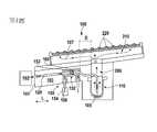
第1圖示出根據本文所述之實施例的蒸發設備100。蒸發設備100包括用於蒸發液體材料105的蒸發坩鍋110和用於將液體材料供應至蒸發坩鍋110中的材料導管120。因此,待蒸發的源材料可以液態,亦即在高於源材料之熔點溫度的溫度下供應至蒸發坩鍋110。例如,源材料可在材料加熱器102中加熱以自固態變為液態,且隨後可經由材料導管120導向蒸發坩鍋110。材料導管120可為管,例如由適合的金屬製成的管,例如鋼或鈦。材料導管120可延伸穿過可加熱至高溫的可加熱外殼或腔室101,使得液體材料105在材料導管120中經由可加熱外殼或腔室101流向蒸發坩鍋110時保持液態。Figure 1 shows an
液體材料105可在蒸發坩鍋110中加熱至高於液體材料之蒸發溫度的溫度。液體材料105在蒸發坩鍋中蒸發以形成蒸發材料107,此蒸發材料可經由蒸氣導管206導引至具有複數個噴嘴220的蒸氣分配器210中,此些噴嘴用於將蒸發材料107導向待塗覆的基板。The
在下文中,將針對作為待蒸發源材料的鋰描述一或多個蒸發概念。根據可與本文所述的其他實施例組合的一些實施例,蒸發概念亦可適用於其他源材料。特定言之,蒸發概念可適用於高反應性材料,例如鹼金屬或鹼土金屬。此外,蒸發概念可有益地用於高沉積速率,從而導致基板上的層厚度為幾微米或更大,尤其在卷對卷塗覆設備(「R2R塗覆機」)中。In the following, one or more evaporation concepts will be described with respect to lithium as the source material to be evaporated. According to some embodiments, which may be combined with other embodiments described herein, the evaporation concept may also be applicable to other source materials. In particular, the evaporation concept can be applied to highly reactive materials such as alkali metals or alkaline earth metals. Furthermore, the evaporation concept can be beneficially used for high deposition rates, resulting in layer thicknesses on substrates of a few microns or more, especially in roll-to-roll coating equipment ("R2R coaters").
在一些實施例中,蒸發設備100經配置用於閃蒸。特定言之,蒸發坩鍋110可經配置用於閃蒸且可在蒸發材料的預定量下相對於蒸發坩鍋的填充高度自調節。或者或此外,流量計可連接至材料導管120以量測液體材料的流量,和/或可在材料導管處設置具有調節元件的調節閥(第1圖中未示出)。In some embodiments,
在閃蒸器中,蒸發坩鍋中只有少量液體材料,此液體材料在極短的時間內蒸發(「閃蒸」)。液體材料105可例如藉由定量泵尤其以小流動速率經由材料導管連續進料至坩鍋中。對於閃蒸,蒸發速率可由供應至蒸發坩鍋之液體材料的量來控制,例如由定量泵提供之液體材料的量和/或液體材料進入蒸發坩鍋的流動速率來控制。蒸發速率可不由蒸發坩鍋的溫度控制。In a flasher, there is only a small amount of liquid material in the evaporation crucible, which evaporates ("flashes") in a very short period of time. The
在其他實施例中,蒸發坩鍋110可為坩鍋,其中可容納更大量的待蒸發液體材料。此處,蒸發速率(亦)可藉由調節蒸發坩鍋中的溫度來控制。例如當蒸發坩鍋中的液體材料低於預定量時,液體材料可經由材料導管120連續地或間隔地供應至蒸發坩鍋110。在任何情況下,鑒於材料的高反應性,蒸發坩鍋中一次少量的液體材料可能係有益的。In other embodiments, the
為了停止蒸發坩鍋中的材料蒸發,可用封閉閥封閉材料導管。例如,停止經由材料導管的材料供應對於維護目的、清洗目的和/或基板上材料沉積的暫時中斷或中止可能係有益的。然而,用於液體材料的習知封閉閥可能不適用於用高反應性材料封閉材料導管。例如,習知閥的封閉元件可能會受液體材料腐蝕,或者液體材料與可能與液體材料接觸的閥部件之間可能存在化學反應的風險,從而導致起火或爆炸。In order to stop the evaporation of the material in the evaporation crucible, the material conduit can be closed with a closing valve. For example, stopping the supply of material via the material conduit may be beneficial for maintenance purposes, cleaning purposes and/or temporary interruption or cessation of material deposition on the substrate. However, conventional closing valves for liquid materials may not be suitable for closing material conduits with highly reactive materials. For example, the closing elements of conventional valves may be corroded by the liquid material, or there may be a risk of a chemical reaction between the liquid material and valve components that may come into contact with the liquid material, resulting in a fire or explosion.
根據本文所述的實施例,蒸發設備100包括閥150,此閥適用於封閉材料導管120,即使高反應性液體材料流過材料導管120。閥150經配置為藉由用冷卻裝置152固化材料導管120中之液體材料的部分來封閉材料導管120。According to the embodiments described herein, the
換言之,閥150包括冷卻裝置152,此冷卻裝置經配置為將材料導管120中的液體材料冷卻至低於液體材料之熔點溫度的溫度,使得液體材料的一部分固化(或「冷凍」)且因此阻塞用於進入液體材料的材料導管120。材料導管120中之材料的固化部分因此構成用於固化材料上游之液體材料的插塞且阻塞材料導管。因此,閥150可被稱為「冷凍閥」,其藉由冷凍流過材料導管之液體材料的一部分來封閉材料導管120。In other words, the
冷凍閥通常使用液體冷卻介質藉由冷凍液體材料來停止材料導管中之液體材料的流動。諸如水或油的液體冷卻介質具有以下優點:液體冷卻介質可送走大的熱負載,且因此可在小的冷卻交互作用區域內快速冷卻且冷凍材料。然而,液體冷卻介質在高溫環境中可能存在嚴重問題,尤其在諸如鋰的反應材料近旁。在高溫下,例如高於熔點,鹼金屬與液體(諸如水,且甚至油)極具反應性,從而引起火災和爆炸危險的風險。Freeze valves typically use a liquid cooling medium to stop the flow of liquid material in a material conduit by freezing the liquid material. A liquid cooling medium, such as water or oil, has the advantage that the liquid cooling medium can carry away large heat loads and thus can rapidly cool and freeze the material in a small area of cooling interaction. However, liquid cooling media can present serious problems in high temperature environments, especially in the vicinity of reactive materials such as lithium. At high temperatures, eg above the melting point, alkali metals are very reactive with liquids, such as water, and even oils, creating a risk of fire and explosion hazards.
為了減少或避免上述風險,本文所述實施例之閥150的冷卻裝置152可使用冷卻氣體106,特定言之惰性氣體,更特定言之氬氣來冷卻和冷凍材料導管120中的液體材料。To reduce or avoid the aforementioned risks, the
在可與本文所述的其他實施例組合的一些實施例中,閥150包含用於將冷卻氣體106導引至冷卻裝置152的冷卻氣體供應器154,且冷卻裝置152經配置為用冷卻氣體106冷卻液體材料。特定言之,冷卻裝置152可為熱交換器,其經配置為將熱量自液體材料傳遞至冷卻氣體106,使得液體材料在材料導管120中冷卻至低於熔化溫度的溫度且在材料導管120中固化。In some embodiments that may be combined with other embodiments described herein,
在一些實施例中,冷卻氣體供應器154可為惰性氣體供應器,特定言之氬氣供應器。氬氣為適合的冷卻氣體,用於冷卻反應材料,特定言之諸如鋰的反應金屬,即使在高溫環境中。惰性氣體與反應液體材料之間發生化學反應的風險係低的或甚至可忽略的,使得冷卻氣體可靠近材料導管120佈置,且甚至可佈置在靠近蒸發坩鍋110的位置,而沒有火災或爆炸的風險。In some embodiments, the cooling
例如,冷卻氣體供應器154可包括冷卻氣體源,例如,氣缸或另一儲氣筒,和/或用於將冷卻氣體供應至可加高溫環境中的氣體供應線或管,特定言之可加熱外殼或腔室101,材料導管120可佈置在此可加熱外殼或腔室中。冷卻氣體供應器154可將冷卻氣體106供應至與材料導管120熱接觸佈置的冷卻裝置152,使得流過材料導管120的液體材料可用冷卻氣體106可靠地冷卻。For example, cooling
在一些實施例中,冷卻裝置152可為具有用於冷卻介質之冷卻通道153的熱交換器,此冷卻介質至少部分地圍繞材料導管120以用於冷卻材料導管120中的液體材料。冷卻通道153可與材料導管120熱接觸且可包括用於沿著材料導管的區段導引冷卻氣體106的管。特定言之,冷卻通道153可為用於冷卻氣體106的管,其至少部分地或完全地圍繞材料導管120且沿著材料導管120的區段延伸。例如,冷卻通道153在材料導管120之長度方向L上的延伸可為5 cm或更多,特定言之10 cm或更多,和/或30 cm或更少。In some embodiments, the
與用冷卻液體冷卻液體材料相比,用冷卻氣體冷卻液體材料可能更困難,此係因為氣體的冷卻能力一般低於諸如水之液體的冷卻能力。提供具有任何以下特徵的冷卻氣體供應器154允許用冷卻氣體可靠地冷卻液體材料,特定言之液體鋰:冷卻氣體供應器154可經配置為導引冷卻氣體106按以下中的至少一者穿過冷卻裝置152的冷卻通道153:(i) 2巴至20巴範圍內,特定言之5巴至15巴範圍內,更特定言之約10巴的氣體壓力,(ii) 15 m/s至50 m/s範圍內,特定言之20 m/s至30 m/s範圍內的氣體速度,以及(iii) 10 slm至50 slm(每分鐘標準公升)範圍內,特定言之15 slm至25 slm範圍內,例如約 20 slm的質量流量。在一些實施例中,經由冷卻通道之冷卻氣體的容積流量可為2 l/min至5 l/min,特定言之2.5 l/min至3 l/min。在一個實例中,冷卻氣體(例如,氬氣)在約10巴的壓力下以約2.7 l/分鐘的容積流量供應穿過冷卻通道,使得獲得約20 slm之穿過材料導管之冷卻氣體的質量流量。Cooling a liquid material with a cooling gas may be more difficult than cooling a liquid material with a cooling liquid because the cooling capacity of a gas is generally lower than that of a liquid such as water. Providing the cooling
冷卻氣體供應器154可經配置為在冷卻通道153的上游位置(冷卻裝置152的位置,在此位置,冷卻氣體與液體材料之間開始熱交換)處以15℃或更高且150℃或更低的溫度將冷卻氣體供應至冷卻通道153。例如,可在室溫下供應冷卻氣體。特定言之,冷卻氣體可由冷卻氣體供應器提供,此冷卻氣體供應器經配置為在室溫下向冷卻裝置提供冷卻氣體。The cooling
液體材料105可為溫度高於材料導管120中冷卻裝置152上游位置處之液體金屬之熔點溫度的液體金屬。液體金屬可為具有約183℃之熔點溫度(熔點溫度可取決於壓力)的液體鋰。冷卻裝置152上游之材料導管120中之液體鋰的溫度可為200℃或更高,特定言之300℃或更高,或甚至400℃或更高,和/或800℃或更低,特定言之700℃或更低,更特定言之600℃或更低。The
在可與本文所述的其他實施例組合的一些實施例中,冷卻裝置152為具有冷卻通道153的熱交換器,此冷卻通道圍繞材料導管120的區段且與材料導管120熱接觸。In some embodiments, which may be combined with other embodiments described herein, the
冷卻通道153可圍繞材料導管120的區段環形地延伸。例如,冷卻通道153中之冷卻氣體的主流向可基本上對應於材料導管中之液體材料的主流向,或可與之相反。The cooling
在一些實施例中,冷卻通道153圍繞材料導管120呈螺旋狀或螺旋形延伸,如第2圖中示意性描繪的。冷卻氣體與液體材料之間的冷卻交互作用區域可藉由冷卻通道153圍繞材料導管的螺旋延伸而增加,同時在冷卻通道中提供預定的冷卻氣體速度。In some embodiments, the cooling
在一些實施例中,冷卻裝置152與蒸發坩鍋110之間的距離D為50 cm或更小,特定言之30 cm或更小,或甚至20 cm或更小。因此,冷卻裝置152可佈置在材料導管120處靠近蒸發坩鍋110的位置處。若藉由使材料導管中之液體材料的部分固化來將閥150切換至封閉狀態,則冷卻裝置與蒸發坩鍋之間的材料導管中僅殘留少量液體材料,使得閥封閉之後設備中的反應材料可保持少量。這提高例如在系統維護中斷或保養中斷的情況下的安全性。In some embodiments, the distance D between the cooling
在可與本文所述的其他實施例組合的一些實施例中,蒸發設備100包括材料導管120延伸穿過的可加熱外殼或腔室101。視情況,蒸發坩鍋110、蒸氣導管206和蒸氣分配器210中的任一者亦可佈置在所述可加熱外殼或腔室101內部。可提供一或多個加熱元件來加熱可加熱外殼或腔室101的內部容積103。例如,可加熱外殼或腔室101的內部容積103可加熱至高於液體材料之熔點溫度的溫度,例如加熱至200℃或更高、300℃或更高,或甚至400℃或更高的溫度。這確保液體材料105在流過材料導管120時保持液態且閥150處於打開狀態。In some embodiments, which may be combined with other embodiments described herein, the
冷卻裝置152可佈置在材料導管120處可加熱外殼或腔室101內部的位置處,例如在靠近蒸發坩鍋110的位置處。特定言之,冷卻裝置152的冷卻通道153可在可加熱外殼或腔室101內部的位置處圍繞材料導管120。因此,冷卻裝置152經佈置在蒸發製程期間大體上熱的環境中,例如在300℃或更高的溫度下提供。其他閥類型可能不適用於這種熱環境。另一方面,本文所述的冷凍閥,特定言之本文所述的冷卻氣體冷凍閥,可佈置在可加熱外殼或腔室101之所述熱環境中的材料導管處,而沒有閥之封閉元件磨損的風險。此外,不存在與閥部件發生化學反應的風險,因為即使在閥封閉狀態下,亦不存在閥部件與液體材料的直接接觸,且液體材料與冷卻惰性氣體之間的化學反應風險——若存在任何接觸——係可忽略的,或根本沒有反應風險。The
為了確保冷凍閥即使在可加熱外殼或腔室的高溫環境中亦能正常運作,可提供絕熱裝置160。絕熱裝置160可部分地或完全地圍封冷卻裝置152,用於將冷卻裝置和冷卻裝置圍繞之材料導管的區段與可加熱外殼或腔室101內部的熱環境絕熱。特定言之,冷卻裝置152的冷卻通道153可部分地或完全地由絕熱裝置160圍封或圍繞。In order to ensure the proper functioning of the freezer valve even in high temperature environments that can heat the enclosure or chamber,
此外,佈置在可加熱外殼或腔室101內部之冷卻氣體供應器154的部分利用絕熱裝置160可相對於可加熱外殼或腔室101的內部容積103絕熱。例如,冷卻氣體供應器154的冷卻氣體供應管可由絕熱元件圍繞,例如隔熱罩。Furthermore, the part of the cooling
在一些實施例中,絕熱裝置160包括至少一個隔熱罩,此隔熱罩圍繞佈置有冷卻裝置152之材料導管120的區段和冷卻裝置152。特定言之,絕熱裝置160可包括兩個或更多個管狀隔熱罩,此些管狀隔熱罩可圍繞材料導管同軸式延伸且至少部分地或完全地圍封冷卻裝置。In some embodiments, the
在一些實施例中,蒸發坩鍋110經配置為蒸發反應材料,特定言之鹼金屬和鹼土金屬中的至少一者,更特定言之鋰。In some embodiments, the
在本文所述的一些實施方案中,冷卻裝置152經配置為將材料導管120中之液體材料的至少部分自300℃或更高的第一溫度冷卻至180℃或更低的第二溫度,特定言之其中第一溫度高於液體材料的熔點溫度且第二溫度低於液體材料的熔點溫度。第一溫度可為400℃或更高,和/或第二溫度可為150℃或更低。In some embodiments described herein,
在一些實施例中,閥150包括用於冷卻氣體的冷卻介質迴路。此處,利用冷卻氣體供應器將冷卻氣體供應至冷卻裝置152,用於冷卻液體材料,且冷卻裝置下游的加熱冷卻氣體經再次冷卻以重新供應至冷卻裝置。可提供用於冷卻氣體的封閉冷卻迴路。In some embodiments,
在其他實施例中(如第1圖所示),利用冷卻氣體供應器154將冷卻氣體供應至冷卻裝置152,用於冷卻液體材料,且冷卻裝置152下游的加熱冷卻氣體經由排氣管排放至環境空氣中。例如,若冷卻氣體為惰性氣體,例如氬氣,則將冷卻氣體排放至冷卻裝置下游的環境空氣中提供了具有成本效益且緊湊的封閉閥。In other embodiments (as shown in FIG. 1 ), a cooling
視情況,蒸發設備可進一步包括用於量測材料導管中之液體材料之流動速率的流量計和/或用於調整蒸發坩鍋中之蒸發速率之具有調節元件的流量閥,此調節元件用於調節穿過材料導管之液體材料的流量。Optionally, the evaporation apparatus may further comprise a flow meter for measuring the flow rate of the liquid material in the material conduit and/or a flow valve with a regulating element for adjusting the evaporation rate in the evaporation crucible for Regulates the flow of liquid material through the material conduit.
第2圖為根據本文所述實施例之蒸發設備之閥150的示意圖。蒸發設備可包括上述蒸發設備100的一些特徵或全部特徵,從而可參考上述解釋,此些解釋在此不再贅述。FIG. 2 is a schematic diagram of a
蒸發設備包括蒸發坩鍋(第2圖中未描繪)和材料導管120,特定言之材料進料管,此材料導管連接至蒸發坩鍋,例如用於將液體材料105供應至蒸發坩鍋。蒸發設備進一步包括閥150,此閥經配置為藉由用冷卻氣體106冷卻材料導管120來封閉材料導管120。閥150可為冷凍閥,其經配置為藉由冷凍流過材料導管之材料的部分來封閉材料導管。The evaporation apparatus comprises an evaporation crucible (not depicted in Figure 2) and a
材料導管120可延伸穿過可加熱外殼或腔室101至蒸發坩鍋。例如,可提供複數個加熱器212,用於將可加熱外殼或腔室101的內部容積103加熱至高於液體材料之熔點溫度的溫度。特定言之,流過材料導管120的液體材料105可為鋰,且可加熱外殼或腔室101可在蒸發製程期間加熱至高於200℃的溫度,特定言之300℃或更高,或甚至400℃或更高。A
閥150可包括用於將冷卻氣體106導引至冷卻裝置152的冷卻氣體供應器154。冷卻裝置152可為具有冷卻通道153的熱交換器,此冷卻通道可圍繞材料導管120的區段且與材料導管120熱接觸。熱交換器可經配置為藉由將熱量自液體材料105傳遞至冷卻通道153中的冷卻氣體106來冷卻液體材料105。
在一些實施例中,冷卻通道153圍繞材料導管120呈螺旋狀延伸。例如,冷卻通道153包括圍繞材料導管120延伸的三個或更多個,或五個或更多個管繞組。冷卻交互作用容積可藉由螺旋形冷卻通道153增加。若冷卻氣體用於冷卻,則大的冷卻交互作用容積和足夠高的氣體流動速率係有益的,因為在除熱方面,冷卻氣體一般不如冷卻液體適合。若冷卻通道與材料導管之間有大的交互作用容積,且提供適合的冷卻通道橫截面和佈置,則液體材料可經由冷卻氣體的冷卻而可靠地固化。In some embodiments, the cooling
在一些實施方案中,冷卻氣體可經配置為自液體材料移除每秒20焦耳或更多(冷卻功率 = 20 W或更多),特定言之每秒30焦耳或更多(冷卻功率 = 30 W或更多)的熱能。在一些實施例中,經由冷卻通道153的冷卻氣體質量流量可在10 slm至50 slm的範圍內,特定言之約20 slm(20 slm對應於在10巴和100℃下約2.7 l/min的容積流量)。在一些實施例中,冷卻通道中的氣體速度可為15 m/s或更大且30 m/s或更小。在一些實施例中,冷卻通道上游的氣體溫度可為15℃或更高且150℃或更低。上述參數範圍經證明適用於用冷卻氣體,特定言之氬氣,可靠地固化液體材料,特定言之鋰。In some implementations, the cooling gas can be configured to remove 20 joules per second or more (cooling power = 20 W or more), specifically 30 joules per second or more (cooling power = 30 joules per second) from the liquid material W or more) thermal energy. In some embodiments, the mass flow of cooling gas through the cooling
在一些實施例中,絕熱裝置160圍封冷卻裝置152。絕熱裝置160可包括兩個、三個或更多個隔熱罩162,此些隔熱罩可為管狀的和/或可經配置用於將冷卻裝置152和/或冷卻氣體供應器154與可加熱外殼或腔室101的(熱)內部空間絕熱。兩個、三個或更多個隔熱罩162(在第2圖中以虛線表示)可圍繞材料導管同軸式延伸且可至少部分地或完全地圍封冷卻裝置。例如,三個或更多個同軸式佈置的隔熱罩可圍繞材料導管的區段。In some embodiments,
當冷卻氣體供應器154的冷卻氣體進料管經絕熱時,可避免冷卻氣體106在冷卻氣體進料管延伸經過之可加熱外殼或腔室101的熱環境中經過度加熱。當絕熱裝置160圍封佈置有冷卻裝置之材料導管的部分時,可避免若閥處於封閉狀態,亦即當冷卻氣體流過冷卻通道以固化液體材料時,經冷卻氣體固化的材料在可加熱外殼或腔室101內部的高溫環境中熔化。When the cooling gas feed tube of the cooling
絕熱裝置160,特定言之兩個、三個或更多個隔熱罩162,可與可加熱外殼或腔室101外部的散熱器熱接觸,使得絕熱裝置160上的熱負載可向散熱器傳導散熱。例如,隔熱罩可經由支撐冷卻氣體供應器的金屬連接來傳導散熱。
在一些實施例中,絕熱裝置160在材料導管120的長度方向L上沿著材料導管120的長度比冷卻裝置152在長度方向L上的長度大例如50%或更多。例如,絕熱裝置160可在長度方向L上延伸超過冷卻裝置152的一端或兩端4 cm或更多,特定言之5 cm或更多的距離。可進一步減少或避免自可加熱外殼或腔室101之熱內部環境至冷卻裝置圍繞之材料導管之可冷卻區段的過度熱輻射。In some embodiments, the
根據本文所述的實施例,藉由經由冷卻裝置152的冷卻通道153供應冷卻氣體106直至材料導管120中之液體材料的部分固化且阻塞材料導管120,閥150自打開狀態切換至封閉狀態。According to embodiments described herein,
藉由以預定溫度、流動速率和/或氣體壓力連續供應冷卻氣體106穿過冷卻通道153,可保持封閉狀態。The closed state can be maintained by continuously supplying the cooling
根據本文所述的實施例,藉由停止經由冷卻通道153供應冷卻氣體106,閥150自封閉狀態切換回打開狀態。可加熱外殼或腔室101內部的熱環境可提供足夠的熱量來熔化材料導管中的固化材料,從而使材料導管例如在10秒或更短的時段內快速重開。特定言之,可不提供用於加熱固化材料的附加加熱裝置。確切言之,當閥處於打開狀態時,亦即沒有供應冷卻介質時,以任何方式提供用於加熱可加熱外殼或腔室101的加熱器212可提供足夠的熱量用於熔化材料導管中的固化材料。According to the embodiments described herein, by ceasing the supply of cooling
根據本文所述的實施例,提供了一種用於封閉蒸發設備之材料導管的小型且具有成本競爭力的冷凍閥。閥反應速度快,且可安裝在材料導管處靠近蒸發設備的位置。閥可為冷卻氣體冷凍閥,亦即將冷卻氣體作為冷卻介質的冷凍閥。冷卻氣體冷凍閥亦可用於封閉材料導管,以導引高反應性材料,諸如鋰。消除了與液體冷卻介質相關的潛在安全隱患。According to embodiments described herein, a small and cost-competitive freeze valve for closing material conduits of an evaporation apparatus is provided. The valve responds quickly and can be installed close to the evaporation equipment at the material conduit. The valve may be a cooling gas freezing valve, that is, a freezing valve in which the cooling gas is used as the cooling medium. Cooling gas freezing valves can also be used to close material conduits to channel highly reactive materials such as lithium. Potential safety hazards associated with liquid cooling media are eliminated.
第3圖為根據本文所述實施例之用於塗覆基板10之蒸氣沉積設備200的示意圖。蒸氣沉積設備200包括根據本文所述之任一實施例的蒸發設備100,從而可參考上述解釋,此些解釋在此不再贅述。FIG. 3 is a schematic diagram of a
蒸氣沉積設備200進一步包括具有複數個噴嘴220的蒸氣分配器210,用於將在蒸發坩鍋110中蒸發的材料導向基板;以及可移動的基板支撐件,特定言之塗覆鼓輪230,用於移動基板10經過蒸氣分配器210。The
蒸氣沉積裝置200可具有可根據上述蒸發設備100配置的複數個蒸發設備,例如,兩個、三個或更多個蒸發設備。在第3圖中,示意性地描繪了另外兩個蒸發設備260。此些蒸發設備可沿著基板輸送路徑一個接一個地佈置,使得可由此些蒸發設備在基板上沉積若干層不同的塗覆材料或一層厚的一種塗覆材料。此些蒸發設備可沿著塗覆鼓輪230的周邊佈置,使得在塗覆鼓輪230上導引的基板10可隨後由此些蒸發設備塗覆。The
蒸氣沉積設備200可經配置用於在R2R塗覆機中塗覆可撓性基板,諸如卷材或箔。卷材可由塗覆鼓輪230上的滾輪導引。塗覆鼓輪230可圍繞旋轉軸旋轉,如箭頭所示,且使卷材移動穿過蒸發設備的處理區域。在一些實施例中,可撓性基板包括金屬箔,特定言之銅箔。或者或此外,可撓性基板可包括石墨、矽和氧化矽中的任一者。
蒸發設備和塗覆鼓輪至少部分地安置在真空沉積腔室(第3圖中未示出)內。蒸發設備的處理區域在真空沉積腔室內。The evaporation equipment and coating drum are at least partially housed within a vacuum deposition chamber (not shown in Figure 3). The processing area of the evaporation apparatus is within the vacuum deposition chamber.
根據可與本文所述的其他實施例組合的一些實施例,可提供可加熱罩250,其至少部分地自蒸發設備100向塗覆鼓輪230延伸且限定蒸發設備100的塗覆窗。可加熱罩250係可加熱的,使得當可加熱罩加熱至操作溫度(例如一些實施例中之500℃或更高的操作溫度,諸如500℃至600℃)時,可減少或防止可加熱罩250上的蒸氣冷凝。防止可加熱罩上的蒸氣冷凝係有益的,因為可減少清洗工作。此外,可加熱罩250上的塗層可改變由可加熱罩提供之塗覆窗的尺寸。此外,當可加熱罩上沒有源材料累積時,可提高源材料利用率。撞擊在操作溫度下提供之可加熱罩250的蒸氣可立即自可加熱罩表面重新蒸發或反射,使得各自的蒸氣分子最終在基板表面上而不是在可加熱罩表面上。可減少或防止可加熱罩上的材料累積,且可減少清洗工作。According to some embodiments, which may be combined with other embodiments described herein, a
本文所述的蒸發坩鍋、蒸氣沉積設備和蒸發方法可尤其用於沉積鋰。鋰可沉積在薄卷材或箔上以提高薄膜電池的大量生產。The evaporation crucibles, vapor deposition apparatus, and evaporation methods described herein are particularly useful for depositing lithium. Lithium can be deposited on thin coils or foils to improve mass production of thin-film batteries.
鋰可例如沉積在薄銅箔上以產生電池的陽極。此外,可在薄卷材或箔上提供包括石墨和/或矽和氧化矽中之至少一者的層。卷材或箔可進一步包括導電層或可由用作陽極接觸表面的導電層組成。沉積在卷材上之層上的鋰可提供包括石墨以及矽和氧化矽中之至少一者之層的預鋰化。Lithium can be deposited, for example, on thin copper foils to create the anode of the battery. Furthermore, a layer comprising graphite and/or at least one of silicon and silicon oxide can be provided on a thin coil or foil. The coil or foil may further comprise a conductive layer or may consist of a conductive layer serving as an anode contact surface. Lithium deposited on the layer on the coil may provide pre-lithiation of the layer including graphite and at least one of silicon and silicon oxide.
對於大量生產,高沉積速率係有益的。然而,尤其在卷對卷沉積製程中,卷材或箔極薄。基板上的熱傳遞由蒸發材料的冷凝能支配。此外,在真空製程中自基板除熱由熱傳導支配。因此,蒸氣沉積設備有益地包括經配置為有效地自基板10除熱的塗覆鼓輪。例如,塗覆鼓輪230可為氣墊塗覆鼓輪,其經配置用於在鼓輪表面與基板之間提供冷卻氣體。For mass production, high deposition rates are beneficial. However, especially in roll-to-roll deposition processes, the web or foil is extremely thin. Heat transfer on the substrate is dominated by the condensation energy of the evaporating material. Furthermore, heat removal from the substrate in the vacuum process is dominated by thermal conduction. Accordingly, the vapor deposition apparatus beneficially includes a coating drum configured to effectively remove heat from the
第4圖為用於說明根據本文所述實施例之蒸發方法的流程圖。FIG. 4 is a flow chart illustrating an evaporation method according to embodiments described herein.
在框410中,液體材料經導引穿過材料導管進入蒸發坩鍋。液體材料可為反應材料,例如反應金屬。特定言之,液體材料可為鹼金屬或鹼土金屬,特定言之鋰。在經導引穿過材料導管之前,固體源材料可在材料加熱器中加熱至高於固體源材料熔點的溫度以提供液體材料。視情況,可用定量泵將液體材料泵送穿過材料導管。In
在框420中,液體材料在蒸發坩鍋中蒸發以形成蒸發材料。特定言之,液體材料在蒸發坩鍋中加熱至高於源材料蒸發溫度的溫度。In
視情況,蒸發坩鍋可經配置用於液體材料的閃蒸。蒸發坩鍋可具有一或多個側壁,以及一或多個側壁下方的儲存器部分,儲存器部分具有第一尺寸的第一橫截面和第二尺寸之高於第一橫截面的第二橫截面,第二尺寸大於第一尺寸。一或多個側壁和儲存器部分可形成為一體,且/或蒸發坩鍋可至少部分地由鋼、Mo、Ta或其組合製成。Optionally, the evaporation crucible may be configured for flash evaporation of liquid materials. The evaporation crucible may have one or more side walls, and a reservoir portion below the one or more side walls, the reservoir portion having a first cross-section of a first dimension and a second cross-section of a second dimension higher than the first cross-section. cross section, the second dimension is greater than the first dimension. One or more of the side walls and the reservoir portion may be integrally formed, and/or the evaporation crucible may be at least partially made of steel, Mo, Ta, or a combination thereof.
在框430中,蒸發材料自蒸發坩鍋經由蒸氣導管導引至蒸氣分配器中,且自蒸氣分配器經由複數個蒸氣噴嘴導引至基板以在真空腔室中塗覆基板。基板可為可撓性基板,其在塗覆期間在塗覆鼓輪上移動經過蒸氣分配器。In
在框440中,藉由特定言之經由用冷卻介質冷卻,更特定言之經由用冷卻氣體冷卻使材料導管中之液體材料的部分固化來封閉材料導管。冷卻氣體可為惰性氣體,特定言之氬氣。若蒸發坩鍋經配置用於閃蒸,封閉材料導管會迅速停止坩鍋中的材料蒸發。In
特定言之,在框440中,冷卻介質可經導引穿過冷卻裝置的冷卻通道,此冷卻通道圍繞材料導管的區段且與材料導管熱接觸。因此,佈置在材料導管之所述區段中之液體材料的部分經冷卻且固化,使得材料導管經固化材料阻塞。In particular, in
冷卻裝置中的冷卻氣體可具有以下中的至少一者:(i)在冷卻通道的上游位置處,15℃或更高且150℃或更低的溫度,(ii) 2巴至20巴範圍內的氣體壓力,(iii) 15 m/s至50 m/s範圍內的氣體速度,以及(iv) 10 slm至50 slm範圍內(例如約20 slm)的質量流量。The cooling gas in the cooling device may have at least one of: (i) a temperature of 15°C or higher and 150°C or lower at an upstream position of the cooling channel, (ii) in the range of 2 bar to 20 bar gas pressure, (iii) gas velocity in the range of 15 m/s to 50 m/s, and (iv) mass flow in the range of 10 slm to 50 slm (eg about 20 slm).
在框450中,藉由停止經由冷卻通道供應冷卻氣體來重開材料導管。這可能會自動導致材料導管中的固化材料熔化,例如當冷卻裝置佈置在材料導管延伸穿過之可加熱外殼或腔室的高溫環境中時。In
上述實施例主要依靠用於冷凍閥之作為冷卻介質的冷卻氣體。應當注意,其他冷卻介質亦可用於冷凍閥,例如用於封閉另一源材料(例如僅為弱反應性或非反應性的源材料)的材料導管。例如,液體冷卻介質可為甚至適用於某些反應材料的油。The above-described embodiments mainly rely on the cooling gas used as the cooling medium for the freezing valve. It should be noted that other cooling media may also be used for the freeze valve, such as a material conduit for enclosing another source material (eg only a weakly reactive or non-reactive source material). For example, the liquid cooling medium may be even oil suitable for certain reactive materials.
材料導管在本文中主要被描述為用於將液體材料供應至材料蒸發器的材料供應導管。應當注意,材料供應器亦可為連接至蒸發坩鍋的另一材料導管,例如將蒸發材料自蒸發坩鍋導引至蒸氣分配器的蒸氣導管。蒸氣導管可藉由用本文所述的冷卻裝置冷凝蒸氣導管中的蒸發材料來封閉。The material conduit is mainly described herein as a material supply conduit for supplying liquid material to the material evaporator. It should be noted that the material supply may also be another material conduit connected to the evaporation crucible, eg a vapour conduit leading the evaporation material from the evaporation crucible to the vapour distributor. The vapor conduit can be closed by condensing the evaporative material in the vapor conduit with the cooling device described herein.
特定言之,本文描述了以下實施例: 實施例1:一種蒸發設備,其包含:蒸發坩鍋,其用於蒸發液體材料;材料導管,其用於將此液體材料供應至此蒸發坩鍋中;以及閥,其經配置為藉由用冷卻裝置使此材料導管中之此液體材料的部分固化來封閉此材料導管。 實施例2:根據實施例1所述之蒸發設備,其中此閥進一步包含用於將冷卻氣體引導至此冷卻裝置的冷卻氣體供應器,此冷卻裝置經配置為用此冷卻氣體冷卻此液體材料。 實施例3:根據實施例2所述之蒸發設備,其中此冷卻氣體供應器為惰性氣體供應器,特定言之氬氣供應器。 實施例4:根據實施例2或3所述之蒸發設備,其中此冷卻氣體供應器經配置為導引此冷卻氣體按以下中的至少一或多者穿過此冷卻裝置的冷卻通道:(i) 2巴至20巴範圍內的氣體壓力,(ii) 15 m/s至50 m/s範圍內的氣體速度,以及 (iii) 10 slm至50 slm範圍內的質量流量。 實施例5:根據實施例1至4中任一項所述之蒸發設備,其中此冷卻裝置包含圍繞此材料導管之區段且與此材料導管熱接觸的冷卻通道。 實施例6:根據實施例5所述之蒸發設備,其中此冷卻通道圍繞此材料導管呈螺旋狀或螺旋形延伸。 實施例7:根據實施例1至6中任一項所述之蒸發設備,其中此冷卻裝置與此蒸發坩鍋之間的距離為20 cm或更小。 實施例8:根據實施例1至7中任一項所述之蒸發設備,其進一步包含此材料導管延伸穿過其中的可加熱外殼或腔室,其中此冷卻裝置佈置在此可加熱外殼或腔室內部的此材料導管處。 實施例9:根據實施例8所述之蒸發設備,其進一步包含至少部分地或完全地圍封此冷卻裝置的絕熱佈置,用於將此冷卻裝置和此冷卻裝置圍繞之此材料導管的區段與此可加熱外殼或腔室內部的熱環境絕熱。 實施例10:根據實施例9所述之蒸發設備,其中此絕熱佈置包含圍繞此材料導管同軸式延伸的一或多個隔熱罩。 實施例11:根據實施例1至10中任一項所述之蒸發設備,其中此蒸發坩鍋經配置為蒸發反應材料,特定言之鋰。 實施例12:一種蒸發設備,其包含:蒸發坩鍋;材料導管,其與此蒸發坩鍋相連接;以及閥,其經配置成為藉由用冷卻氣體冷卻此材料導管來封閉此材料導管。此蒸發設備可視情況進一步包括任何前述實施例的任何特徵。 實施例13:一種用於塗覆基板的蒸氣沉積設備,其包含:根據任何前述實施例所述之蒸發設備;蒸氣分配器,其具有複數個噴嘴,用於將在此蒸發坩鍋中蒸發的材料導向此基板;以及可移動基板支撐件,用於移動此基板經過此蒸氣分配器。 實施例14:一種蒸發方法,其包含以下步驟:將液體物料經由材料導管導入蒸發坩鍋中;蒸發此蒸發坩鍋中的此液體材料;以及藉由使此材料導管中之此液體材料的部分固化來封閉此材料導管。 實施例15:根據實施例14所述之方法,其中此液體材料的此部分經由用冷卻氣體冷卻來固化。 實施例16:根據實施例15所述之方法,其中此冷卻氣體為氬氣。 實施例17:根據實施例15或16所述之方法,其中此冷卻氣體經導引穿過冷卻裝置的冷卻通道,此冷卻通道圍繞此材料導管的區段。 實施例18:根據實施例17所述之方法,其中此冷卻裝置中的此冷卻氣體具有以下中的至少一者:(i)在此冷卻通道的上游位置處,15℃或更高且150℃或更低的溫度,(ii) 2巴至20巴範圍內的氣體壓力,(iii) 15 m/s至50 m/s範圍內的氣體速度,以及(iv) 10 slm至50 slm範圍內的質量流量。 實施例19:根據實施例17或18之方法,其進一步包含藉由停止經由此冷卻通道進行此冷卻氣體的供應來重開此材料導管。 實施例20:根據實施例14至19中任一項所述之方法,其中此液體材料為鹼金屬或鹼土金屬。 實施例21:根據實施例14至20中任一項所述之方法,其進一步包含以下步驟:將蒸發材料自此蒸發坩鍋導引至蒸氣分配器中;以及將此蒸發材料自此蒸氣分配器經由複數個蒸氣噴嘴導向基板,用於在真空腔室中塗覆此基板。In particular, the following embodiments are described herein: Embodiment 1: An evaporation apparatus comprising: an evaporation crucible for evaporating a liquid material; a material conduit for supplying the liquid material into the evaporation crucible; and a valve configured to cool by using The device solidifies the portion of the liquid material in the material conduit to close the material conduit. Embodiment 2: The evaporation apparatus of Embodiment 1, wherein the valve further comprises a cooling gas supply for directing cooling gas to the cooling device configured to cool the liquid material with the cooling gas. Embodiment 3: The evaporation apparatus according to Embodiment 2, wherein the cooling gas supplier is an inert gas supplier, in particular an argon gas supplier. Embodiment 4: The evaporation apparatus of embodiment 2 or 3, wherein the cooling gas supplier is configured to direct the cooling gas through the cooling passages of the cooling device in at least one or more of the following: (i ) gas pressure in the range 2 bar to 20 bar, (ii) gas velocity in the range 15 m/s to 50 m/s, and (iii) mass flow in the
雖然前述內容係關於實施例,但在不脫離基本範疇的情況下可設計其他和進一步的實施例,且此範疇由所附發明申請專利範圍確定。While the foregoing has been directed to embodiments, other and further embodiments can be devised without departing from the essential scope as determined by the scope of the appended claims.
10:基板 100:蒸發設備 101:可加熱外殼或腔室 102:材料加熱器 103:內部容積 105:液體材料 106:冷卻氣體 107:蒸發材料 110:蒸發坩鍋 120:材料導管 150:閥 152:冷卻裝置 153:冷卻通道 154:冷卻氣體供應器 160:絕熱裝置 162:隔熱罩 200:蒸氣沉積設備 206:蒸氣導管 210:蒸氣分配器 212:加熱器 220:噴嘴 230:塗覆鼓輪 250:可加熱罩 260:蒸發設備 410:框 420:框 430:框 440:框 450:框 D:距離 L:長度方向10: Substrate 100: Evaporation equipment 101: Heatable enclosure or chamber 102: Material heater 103: Internal volume 105: Liquid Materials 106: Cooling gas 107: Evaporation material 110: Evaporation Crucible 120: Material conduit 150: Valve 152: Cooling device 153: Cooling channel 154: Cooling gas supply 160: Insulation device 162: Heat shield 200: Vapor Deposition Equipment 206: Vapor Conduit 210: Vapor distributor 212: Heater 220: Nozzle 230: Coating drum 250: Heatable hood 260: Evaporation equipment 410: Box 420: Box 430: Box 440: Box 450: Box D: distance L: length direction
為了能夠詳細地理解本揭示案的上述特徵,可藉由參考實施例獲得對以上簡要概述之本揭示案的更具體描述。隨附圖式係關於本揭示案的實施例,且描述如下: 第1圖示出根據本揭示案之實施例之蒸發設備的示意圖。 第2圖示出根據本揭示案之實施例之蒸發設備冷凍閥的示意圖。 第3圖示出根據本揭示案之實施例之蒸氣沉積設備的示意圖;以及 第4圖示出說明根據本揭示案之實施例之蒸發方法的流程圖。In order to be able to understand the above-mentioned features of the present disclosure in detail, a more detailed description of the present disclosure, briefly summarized above, can be obtained by referring to the embodiments. The accompanying drawings relate to embodiments of the disclosure and are described as follows: FIG. 1 shows a schematic diagram of an evaporation apparatus according to an embodiment of the present disclosure. FIG. 2 shows a schematic diagram of a freezing valve of an evaporative apparatus according to an embodiment of the present disclosure. FIG. 3 shows a schematic diagram of a vapor deposition apparatus according to an embodiment of the present disclosure; and FIG. 4 shows a flowchart illustrating an evaporation method according to an embodiment of the present disclosure.
國內寄存資訊(請依寄存機構、日期、號碼順序註記) 無 國外寄存資訊(請依寄存國家、機構、日期、號碼順序註記) 無Domestic storage information (please note in the order of storage institution, date and number) none Foreign deposit information (please note in the order of deposit country, institution, date and number) none
100:蒸發設備100: Evaporation equipment
101:可加熱外殼或腔室101: Heatable enclosure or chamber
102:材料加熱器102: Material heater
103:內部容積103: Internal volume
105:液體材料105: Liquid Materials
106:冷卻氣體106: Cooling gas
107:蒸發材料107: Evaporation material
110:蒸發坩鍋110: Evaporation Crucible
120:材料導管120: Material conduit
150:閥150: Valve
152:冷卻裝置152: Cooling device
153:冷卻通道153: Cooling channel
154:冷卻氣體供應器154: Cooling gas supply
160:絕熱裝置160: Insulation device
206:蒸氣導管206: Vapor Conduit
210:蒸氣分配器210: Vapor distributor
220:噴嘴220: Nozzle
D:距離D: distance
L:長度方向L: length direction
Claims (20)
Translated fromChineseApplications Claiming Priority (2)
| Application Number | Priority Date | Filing Date | Title |
|---|---|---|---|
| US17/024,882 | 2020-09-18 | ||
| US17/024,882US20220090256A1 (en) | 2020-09-18 | 2020-09-18 | Evaporation apparatus, vapor deposition apparatus, and evaporation method |
Publications (1)
| Publication Number | Publication Date |
|---|---|
| TW202225439Atrue TW202225439A (en) | 2022-07-01 |
Family
ID=80740026
Family Applications (1)
| Application Number | Title | Priority Date | Filing Date |
|---|---|---|---|
| TW110132012ATW202225439A (en) | 2020-09-18 | 2021-08-30 | Evaporation apparatus, vapor deposition apparatus, and evaporation method |
Country Status (7)
| Country | Link |
|---|---|
| US (2) | US20220090256A1 (en) |
| EP (1) | EP4214350A4 (en) |
| JP (1) | JP2023541654A (en) |
| KR (1) | KR20230069201A (en) |
| CN (1) | CN116034179A (en) |
| TW (1) | TW202225439A (en) |
| WO (1) | WO2022060570A1 (en) |
Cited By (1)
| Publication number | Priority date | Publication date | Assignee | Title |
|---|---|---|---|---|
| CN115094385A (en)* | 2022-07-21 | 2022-09-23 | 浙江艾微普科技有限公司 | Coating equipment and coating method with liquid supply system |
Families Citing this family (2)
| Publication number | Priority date | Publication date | Assignee | Title |
|---|---|---|---|---|
| WO2024249029A1 (en)* | 2023-05-26 | 2024-12-05 | Applied Materials, Inc. | Apparatus and systems for alkali metal deposition |
| CN117344289A (en)* | 2023-11-06 | 2024-01-05 | 甬江实验室 | Chemical vapor deposition apparatus |
Family Cites Families (12)
| Publication number | Priority date | Publication date | Assignee | Title |
|---|---|---|---|---|
| US4082109A (en)* | 1976-09-03 | 1978-04-04 | Hughes Aircraft Company | Heat pipe actuated valve |
| US6578596B1 (en)* | 2000-04-18 | 2003-06-17 | Stratasys, Inc. | Apparatus and method for thermoplastic extrusion |
| JP2002150552A (en)* | 2000-11-08 | 2002-05-24 | Sony Corp | Method and device for manufacturing vapor-deposited tape |
| US7465946B2 (en) | 2004-03-10 | 2008-12-16 | Cymer, Inc. | Alternative fuels for EUV light source |
| LV13383B (en)* | 2004-05-27 | 2006-02-20 | Sidrabe As | Method and device for vacuum vaporization metals or alloys |
| US20100196623A1 (en)* | 2007-10-09 | 2010-08-05 | Kazuyoshi Honda | Film forming method and film forming apparatus |
| PL2663665T3 (en)* | 2011-01-14 | 2015-08-31 | Arcelormittal Investig Y Desarrollo | Automatic feeding device for an industrial metal-vapor generator |
| KR20130119107A (en)* | 2012-04-23 | 2013-10-31 | 삼성에스디아이 주식회사 | Deposition equipment |
| JP6038288B2 (en) | 2013-03-28 | 2016-12-07 | 株式会社日立国際電気 | Substrate processing apparatus, semiconductor device manufacturing method, and program |
| KR101713112B1 (en)* | 2016-07-26 | 2017-03-08 | 에스엔유 프리시젼 주식회사 | Deposition material supply apparatus which can continuously charged |
| CN112074623A (en) | 2018-05-22 | 2020-12-11 | 应用材料公司 | Evaporation source, method for operating an evaporation source and deposition system |
| WO2021013326A1 (en)* | 2019-07-19 | 2021-01-28 | Applied Materials, Inc. | Evaporation source, vacuum deposition system, valve assembly, and method therefor |
- 2020
- 2020-09-18USUS17/024,882patent/US20220090256A1/ennot_activeAbandoned
- 2021
- 2021-08-30TWTW110132012Apatent/TW202225439A/enunknown
- 2021-09-01WOPCT/US2021/048677patent/WO2022060570A1/ennot_activeCeased
- 2021-09-01CNCN202180054212.6Apatent/CN116034179A/enactivePending
- 2021-09-01KRKR1020237012799Apatent/KR20230069201A/enactivePending
- 2021-09-01EPEP21869978.3Apatent/EP4214350A4/enactivePending
- 2021-09-01JPJP2023517256Apatent/JP2023541654A/enactivePending
- 2023
- 2023-12-15USUS18/542,356patent/US12286703B2/enactiveActive
Cited By (1)
| Publication number | Priority date | Publication date | Assignee | Title |
|---|---|---|---|---|
| CN115094385A (en)* | 2022-07-21 | 2022-09-23 | 浙江艾微普科技有限公司 | Coating equipment and coating method with liquid supply system |
Also Published As
| Publication number | Publication date |
|---|---|
| EP4214350A4 (en) | 2025-06-04 |
| EP4214350A1 (en) | 2023-07-26 |
| JP2023541654A (en) | 2023-10-03 |
| WO2022060570A1 (en) | 2022-03-24 |
| US20220090256A1 (en) | 2022-03-24 |
| KR20230069201A (en) | 2023-05-18 |
| US12286703B2 (en) | 2025-04-29 |
| US20240117484A1 (en) | 2024-04-11 |
| CN116034179A (en) | 2023-04-28 |
Similar Documents
| Publication | Publication Date | Title |
|---|---|---|
| TW202225439A (en) | Evaporation apparatus, vapor deposition apparatus, and evaporation method | |
| JP6639580B2 (en) | Evaporator, deposition arrangement, deposition device and method of operating these | |
| JP6647202B2 (en) | Deposition arrangement, deposition device, and method of operation thereof | |
| KR20000022893A (en) | Vaporization equipment for vacuum deposition plant | |
| CN101688290A (en) | Vacuum evaporation apparatus for solid materials | |
| TWI868451B (en) | Close couple diffuser for physical vapor deposition web coating | |
| CN101052738B (en) | Controlled coating of gasified organic materials | |
| TWI839614B (en) | Crucible for flash evaporation of a liquid material, vapor deposition apparatus and method for coating a substrate in a vacuum chamber | |
| CN223201903U (en) | A deposition coating system |