TW202209933A - Apparatus for and method of accelerating droplets in a droplet generator for an euv source - Google Patents
Apparatus for and method of accelerating droplets in a droplet generator for an euv sourceDownload PDFInfo
- Publication number
- TW202209933A TW202209933ATW110121110ATW110121110ATW202209933ATW 202209933 ATW202209933 ATW 202209933ATW 110121110 ATW110121110 ATW 110121110ATW 110121110 ATW110121110 ATW 110121110ATW 202209933 ATW202209933 ATW 202209933A
- Authority
- TW
- Taiwan
- Prior art keywords
- gas
- droplet
- location
- droplets
- zone
- Prior art date
Links
Images


Classifications
- H—ELECTRICITY
- H05—ELECTRIC TECHNIQUES NOT OTHERWISE PROVIDED FOR
- H05G—X-RAY TECHNIQUE
- H05G2/00—Apparatus or processes specially adapted for producing X-rays, not involving X-ray tubes, e.g. involving generation of a plasma
- H05G2/001—Production of X-ray radiation generated from plasma
- H05G2/002—Supply of the plasma generating material
- H05G2/0023—Constructional details of the ejection system
- H—ELECTRICITY
- H05—ELECTRIC TECHNIQUES NOT OTHERWISE PROVIDED FOR
- H05G—X-RAY TECHNIQUE
- H05G2/00—Apparatus or processes specially adapted for producing X-rays, not involving X-ray tubes, e.g. involving generation of a plasma
- H05G2/001—Production of X-ray radiation generated from plasma
- H05G2/002—Supply of the plasma generating material
- H05G2/0027—Arrangements for controlling the supply; Arrangements for measurements
- H—ELECTRICITY
- H05—ELECTRIC TECHNIQUES NOT OTHERWISE PROVIDED FOR
- H05G—X-RAY TECHNIQUE
- H05G2/00—Apparatus or processes specially adapted for producing X-rays, not involving X-ray tubes, e.g. involving generation of a plasma
- H05G2/001—Production of X-ray radiation generated from plasma
- H05G2/003—Production of X-ray radiation generated from plasma the plasma being generated from a material in a liquid or gas state
- H—ELECTRICITY
- H05—ELECTRIC TECHNIQUES NOT OTHERWISE PROVIDED FOR
- H05G—X-RAY TECHNIQUE
- H05G2/00—Apparatus or processes specially adapted for producing X-rays, not involving X-ray tubes, e.g. involving generation of a plasma
- H05G2/001—Production of X-ray radiation generated from plasma
- H05G2/008—Production of X-ray radiation generated from plasma involving an energy-carrying beam in the process of plasma generation
- H05G2/0082—Production of X-ray radiation generated from plasma involving an energy-carrying beam in the process of plasma generation the energy-carrying beam being a laser beam
- G—PHYSICS
- G03—PHOTOGRAPHY; CINEMATOGRAPHY; ANALOGOUS TECHNIQUES USING WAVES OTHER THAN OPTICAL WAVES; ELECTROGRAPHY; HOLOGRAPHY
- G03F—PHOTOMECHANICAL PRODUCTION OF TEXTURED OR PATTERNED SURFACES, e.g. FOR PRINTING, FOR PROCESSING OF SEMICONDUCTOR DEVICES; MATERIALS THEREFOR; ORIGINALS THEREFOR; APPARATUS SPECIALLY ADAPTED THEREFOR
- G03F7/00—Photomechanical, e.g. photolithographic, production of textured or patterned surfaces, e.g. printing surfaces; Materials therefor, e.g. comprising photoresists; Apparatus specially adapted therefor
- G03F7/70—Microphotolithographic exposure; Apparatus therefor
- G03F7/70008—Production of exposure light, i.e. light sources
- G03F7/70033—Production of exposure light, i.e. light sources by plasma extreme ultraviolet [EUV] sources
Landscapes
- Physics & Mathematics (AREA)
- Optics & Photonics (AREA)
- Engineering & Computer Science (AREA)
- Plasma & Fusion (AREA)
- X-Ray Techniques (AREA)
- Exposure And Positioning Against Photoresist Photosensitive Materials (AREA)
Abstract
Description
Translated fromChinese本申請案係關於極紫外(「EUV」)光源及其操作方法。此等光源藉由從源或目標材料產生電漿來提供EUV光。在一種應用中,可收集EUV光並將其用於光微影程序以產生半導體積體電路。This application relates to extreme ultraviolet ("EUV") light sources and methods of operation thereof. These light sources provide EUV light by generating plasma from source or target materials. In one application, EUV light can be collected and used in a photolithography process to create semiconductor integrated circuits.
可使用經圖案化EUV光束來曝露塗有抗蝕劑之基板,諸如矽晶圓,以在基板中或基板上產生極小特徵。極紫外線光(有時亦稱為軟x射線)通常經定義為波長在約5至100 nm範圍內之電磁輻射。光微影所關注的一種特定波長出現在13.5 nm。A patterned EUV beam can be used to expose a resist-coated substrate, such as a silicon wafer, to create extremely small features in or on the substrate. Extreme ultraviolet light (also sometimes referred to as soft x-rays) is generally defined as electromagnetic radiation with wavelengths in the range of about 5 to 100 nm. A specific wavelength of interest for photolithography occurs at 13.5 nm.
產生EUV光之方法包括但不一定限於將源材料轉換為電漿狀態,該電漿狀態具有在EUV範圍中具有發出線之化學元素。此等元素可包括但不一定限於氙、鋰及錫。Methods of generating EUV light include, but are not necessarily limited to, converting the source material into a plasmonic state with chemical elements that have emitting lines in the EUV range. Such elements may include, but are not necessarily limited to, xenon, lithium, and tin.
在一種此類方法(通常稱為雷射產生電漿(「LPP」))中,可藉由用雷射光束輻照源材料(例如呈液滴、流或線形式)來產生所要電漿。在另一通常稱為放電產生電漿(「DPP」)之方法中,可藉由在一對電極之間定位具有適當發出線的源材料並致使在電極之間發生放電來產生所需要電漿。In one such method, commonly referred to as laser generated plasma ("LPP"), the desired plasma can be generated by irradiating a source material (eg, in the form of droplets, streams, or lines) with a laser beam. In another method commonly referred to as discharge-generated plasma ("DPP"), the desired plasma can be generated by positioning a source material with appropriate emission lines between a pair of electrodes and causing a discharge to occur between the electrodes .
一種用於產生液滴之技術涉及熔化目標或源材料(諸如錫),且然後在高壓下迫使液態錫通過直徑相對較小孔口,諸如直徑為約0.5 μm至約30 μm之孔口,以產生液滴流。在大多數情況下,在稱為瑞立(Rayleigh)分裂的程序中,離開孔口的流中自然發生的不穩定性,例如噪音,將導致流分裂成微液滴。此等液滴可具有不同速度且可在其在流中行進以聚結成較大液滴時彼此組合。One technique for generating droplets involves melting a target or source material, such as tin, and then forcing the liquid tin under high pressure through a relatively small diameter orifice, such as an orifice having a diameter of about 0.5 μm to about 30 μm, to A stream of droplets is produced. In most cases, naturally occurring instabilities in the flow leaving the orifice, such as noise, will cause the flow to break up into droplets in a procedure called Rayleigh splitting. These droplets can have different velocities and can combine with each other as they travel in the stream to coalesce into larger droplets.
液滴產生器之任務係將液滴置放在收集鏡之主焦點中,在其處該等液滴將用作EUV產生之燃料。液滴必須在特定空間及時間穩定性標準內到達主焦點,亦即,其中位置及時間在可接受範圍內為可重複的。其亦必須以給定頻率及速度到達。此外,液滴必須完全聚結,意味著液滴必須為單分散(大小均勻)並以給定驅動頻率到達。The task of the droplet generator is to place the droplets in the main focus of the collection mirror, where they will be used as fuel for EUV generation. The droplet must reach the primary focus within certain spatial and temporal stability criteria, ie, where the position and time are within acceptable limits to be repeatable. It must also arrive at a given frequency and speed. Furthermore, the droplets must be fully coalesced, meaning that the droplets must be monodisperse (uniform in size) and arrive at a given drive frequency.
對高重複率之高EUV功率的需求不斷增加驅動對具有較高液滴間距的較高速度液滴的需求。過去,已藉由增加驅動氣體壓力來實現加速由液滴產生器產生的液滴。目前,大約4000 psi (270巴)的壓力用於實現約82 m/sec之液滴速度。未來的EUV設計需要較高速度,此將需要高達15000 psi (1000巴)之驅動壓力才能實現。然而,藉由增加驅動氣體壓力可增加液滴速度程度存在限制。使用如此高壓力呈現多個問題,包括但不限於此等壓力下之材料效能及穩定性、較高壓力下液滴聚結長度的增加、安全性、監理要求等。此外,在給定流體速度及噴嘴幾何形狀下,孔口中之流體流動可變得亂流,導致液滴不穩定。The increasing demand for high EUV power at high repetition rates drives the need for higher velocity droplets with higher droplet spacing. In the past, acceleration of droplets produced by droplet generators has been achieved by increasing the driving gas pressure. Currently, pressures of about 4000 psi (270 bar) are used to achieve droplet velocities of about 82 m/sec. Future EUV designs require higher speeds, which will require drive pressures as high as 15,000 psi (1,000 bar) to achieve. However, there is a limit to the extent to which droplet velocity can be increased by increasing the driving gas pressure. The use of such high pressures presents a number of issues including, but not limited to, material performance and stability at these pressures, increased droplet coalescence length at higher pressures, safety, regulatory requirements, and the like. Furthermore, at a given fluid velocity and nozzle geometry, the fluid flow in the orifice can become turbulent, resulting in droplet instability.
由液滴產生器產生之液滴的氣體加速已認為係一種增加液滴速度而不必增加驅動氣壓的方式。例如,特此以全文引用的方式併入本文中的指定Mestrom等人為發明者且在2013年12月3日發佈的標題為「EUV Radiation Source Comprising a Droplet Accelerator and Lithographic Apparatus」的美國專利第8,598,551號揭示一種EUV輻射源,該EUV輻射源包括液滴加速器,該液滴加速器經組態以使用氣體加速燃料液滴。然而,若實施不恰當,加速氣體的使用會引起液滴流不穩定。Gas acceleration of droplets produced by droplet generators has been considered as a way to increase droplet velocity without necessarily increasing the driving gas pressure. For example, U.S. Patent No. 8,598,551, entitled "EUV Radiation Source Comprising a Droplet Accelerator and Lithographic Apparatus," which designates Mestrom et al. as inventors and issued December 3, 2013, is hereby incorporated by reference in its entirety as disclosed herein. An EUV radiation source includes a droplet accelerator configured to accelerate fuel droplets using a gas. However, if not implemented properly, the use of accelerating gas can cause instability in the droplet flow.
因此需要能夠以不需要高驅動氣壓的方式加速液滴並限制加速氣體使液滴不穩定的任何趨勢。There is therefore a need to be able to accelerate the droplet in a manner that does not require high drive gas pressures and to limit any tendency of the accelerating gas to destabilize the droplet.
下文呈現一或多個實施例的簡化概述,以便提供對實施例的基本理解。此概述並非對所有預期實施例之廣泛概述,且既不意欲識別所有實施例之重要或關鍵要素亦不意欲劃定任何或所有實施例之範疇。該概述之唯一目的係以簡化形式呈現一或多個實施例之一些概念作為稍後呈現之更詳細描述之序言。The following presents a simplified summary of one or more embodiments in order to provide a basic understanding of the embodiments. This summary is not an extensive overview of all contemplated embodiments, and is neither intended to identify important or critical elements of all embodiments nor to delineate the scope of any or all embodiments. The sole purpose of this summary is to present some concepts of one or more embodiments in a simplified form as a prelude to the more detailed description that is presented later.
根據實施例的一個態樣,提供一種液滴產生器,其中液滴在液滴仍聚結為其最終大小之流的初始部分中不曝露於加速氣體流。因此,此「液滴聚結區」之特徵在於不存在任何會干擾液滴達到完全聚結的能力的大量氣流。According to one aspect of an embodiment, a droplet generator is provided in which the droplets are not exposed to the flow of accelerating gas during the initial portion of the flow where the droplets are still coalesced to their final size. Thus, this "droplet coalescence zone" is characterized by the absence of any substantial airflow that would interfere with the ability of the droplets to achieve complete coalescence.
根據實施例的另一態樣,在液滴離開液滴聚結區之後,使用加速氣體來夾帶並加速該等液滴。加速氣體逐漸加速至最大值,因此限制氣流中之擾動。According to another aspect of the embodiment, an accelerating gas is used to entrain and accelerate the droplets after they exit the droplet coalescence zone. The accelerating gas is gradually accelerated to a maximum value, thus limiting disturbances in the gas flow.
根據實施例的另一態樣,在氣體之溫度及壓力下,氣流之最大值低於氣體之聲速。根據其他實施例的其他態樣,在氣體之溫度及壓力下,氣流之最大值與氣體之聲速相同或高於該聲速。According to another aspect of the embodiment, at the temperature and pressure of the gas, the maximum value of the gas flow is lower than the speed of sound of the gas. According to other aspects of other embodiments, at the temperature and pressure of the gas, the maximum value of the gas flow is the same as or higher than the speed of sound of the gas.
根據實施例的另一態樣,熱化傳入氣流,亦即,使其與液滴產生器達到熱平衡以在將氣體引入至液滴產生器之氣體加速區中時,避免熱衝擊。According to another aspect of the embodiment, the incoming gas flow is thermalized, that is, brought into thermal equilibrium with the droplet generator to avoid thermal shock when the gas is introduced into the gas acceleration zone of the droplet generator.
根據實施例的另一態樣,在液滴聚結區之末端附近流動至加速器中之氣體的速度與離開該液滴聚結區之液滴的速度匹配。According to another aspect of the embodiment, the velocity of the gas flowing into the accelerator near the end of the droplet coalescence zone matches the velocity of the droplets exiting the droplet coalescence zone.
根據實施例的一個態樣,揭示一種用於產生EUV源材料之液滴流的液滴產生器,該液滴產生器包含:噴嘴,其經調適以從噴嘴出口發出液態EUV源材料流;第一結構,其界定從噴嘴出口向下游延伸至第一位置的液滴聚結區,其中液態EUV源材料流分裂並聚結成液態EUV源材料之聚結液滴流;至少一個入口,其經調適以連接至氣體之源;及第二結構,其界定從第一位置向下游延伸至第二位置的氣體加速區,與至少一個入口進行流體連通,經配置以在第一位置處接收聚結液滴流,且經調適以致使氣體經引入至在第一位置下游之氣體加速區中並加速且大體上平行於聚結液滴流流向流動以夾帶聚結液滴,液滴聚結區經配置且經組態使得液滴聚結區中之液態EUV源材料未曝露於氣體之流向流動。液滴聚結區之流向長度可在10 mm與200 mm之間,或在20 mm與200 mm之間。此處及別處,術語「可」意味著以下為幾種可能性中之一者。According to one aspect of an embodiment, a droplet generator for generating a stream of droplets of EUV source material is disclosed, the droplet generator comprising: a nozzle adapted to emit a stream of liquid EUV source material from an outlet of the nozzle; a structure defining a droplet coalescence zone extending downstream from the nozzle outlet to a first location in which the stream of liquid EUV source material breaks up and coalesces into a stream of coalesced droplets of liquid EUV source material; at least one inlet adapted to to be connected to a source of gas; and a second structure defining a gas acceleration region extending downstream from the first location to a second location, in fluid communication with the at least one inlet, and configured to receive coalescing liquid at the first location a droplet flow, and adapted such that gas is introduced into a gas acceleration zone downstream of the first location and accelerated and flows substantially parallel to the flow direction of the coalesced droplet stream to entrain coalesced droplets, the droplet coalescence zone is configured And is configured such that the liquid EUV source material in the droplet coalescence region is not exposed to the flow direction flow of the gas. The flow direction length of the droplet coalescence zone may be between 10 mm and 200 mm, or between 20 mm and 200 mm. Here and elsewhere, the term "may" means one of several possibilities.
氣體加速區可具有弧形剖面,該弧形剖面具有在第一位置與第二位置之間減小的內部剖面面積。氣體加速區可具有內部圓形(circular)剖面,其半徑在第一位置與第二位置之間減小。氣體加速區可經組態使得氣體之流向速度不超過氣體之聲速。氣體加速區可經組態使得氣體在第二位置處之流向速度大約但小於氣體之聲速。氣體加速區可經組態使得氣體在第一位置處之流向速度大約等於在第一位置處離開液滴聚結區之聚結液滴之流向速度。氣體可加速聚結液滴氣體,使得在第一位置處進入氣體加速區之聚結液滴在穿過氣體加速區至第二位置時從約80 m/sec加速至約130 m/sec。The gas acceleration zone may have an arcuate cross-section with a reduced internal cross-sectional area between the first position and the second position. The gas acceleration zone may have an inner circular cross-section, the radius of which decreases between the first position and the second position. The gas acceleration zone can be configured such that the flow velocity of the gas does not exceed the sound velocity of the gas. The gas acceleration zone may be configured such that the flow velocity of the gas at the second location is about but less than the sonic velocity of the gas. The gas acceleration zone can be configured such that the flow velocity of the gas at the first location is approximately equal to the flow velocity of the coalesced droplets exiting the droplet coalescence zone at the first location. The gas can accelerate the coalesced droplet gas such that coalesced droplets entering the gas acceleration zone at the first location are accelerated from about 80 m/sec to about 130 m/sec as they pass through the gas acceleration zone to the second location.
液滴產生器可進一步包含熱化結構,該熱化結構經配置以與氣體熱接觸且經調適以熱化氣體以在將氣體引入至氣體加速區中之前與液滴產生器達到熱平衡。熱化結構可經調適以將氣體加熱至在200℃與300℃之間的溫度。液滴產生器可進一步包含源材料加熱器,該源材料加熱器經配置以向液滴產生器中之源材料供應熱,且熱化結構經配置以在源材料加熱器與氣體之間轉移熱。氣體可為具有低EUV吸收率的氣體,例如,氫氣。第一結構及第二結構中之至少一個可包含耐火金屬,其可例如為鉬、鎢、鉭及錸及其合金中之至少一者。第一結構及第二結構中之至少一者可包含氮化硼塗層。The droplet generator may further include a thermalization structure configured to thermally contact the gas and adapted to thermalize the gas to achieve thermal equilibrium with the droplet generator prior to introducing the gas into the gas acceleration zone. The thermalizing structure can be adapted to heat the gas to a temperature between 200°C and 300°C. The droplet generator may further include a source material heater configured to supply heat to the source material in the droplet generator and the thermalization structure configured to transfer heat between the source material heater and the gas . The gas may be a gas with low EUV absorption, eg, hydrogen. At least one of the first structure and the second structure may include a refractory metal, which may be, for example, at least one of molybdenum, tungsten, tantalum, and rhenium, and alloys thereof. At least one of the first structure and the second structure may include a boron nitride coating.
根據實施例的另一態樣,揭示一種加速EUV源材料之液滴之方法,該方法包含:從液滴產生器之噴嘴出口發出液態EUV源材料流;將液態EUV源材料流轉化為界定從噴嘴出口向下游延伸至第一位置的液滴聚結區的第一結構中之聚結液滴流;將第一位置處之聚結液滴流引入至界定從第一位置向下游延伸至第二位置的氣體加速區的第二結構中,將氣流引入至氣體加速區中以大體上平行於聚結液滴流流向流動,在氣體接近第二位置時在氣體加速區中加速氣流,及在氣流中夾帶聚結液滴以加速聚結液滴,液滴加速區經配置且經組態使得液滴聚結區中之液態EUV源材料未曝露於氣體之流向流動。液滴聚結區之流向長度可在10 mm與200 mm之間。液滴聚結區之流向長度可在20mm與100mm之間。According to another aspect of an embodiment, a method of accelerating droplets of EUV source material is disclosed, the method comprising: emitting a stream of liquid EUV source material from a nozzle outlet of a droplet generator; converting the stream of liquid EUV source material into a stream defined from the outlet of the nozzle extends downstream to the coalesced droplet stream in the first structure of the droplet coalescence zone at the first location; introducing the coalesced droplet stream at the first location to define a stream of coalesced droplets extending downstream from the first location to the first location In the second configuration of the two-position gas acceleration zone, a gas stream is introduced into the gas acceleration zone to flow substantially parallel to the flow direction of the coalesced droplets, the gas stream is accelerated in the gas acceleration zone as the gas approaches the second position, and The coalesced droplets are entrained in the gas stream to accelerate the coalesced droplets, and the droplet acceleration zone is configured and configured such that the liquid EUV source material in the droplet coalescence zone is not exposed to the flow direction flow of the gas. The flow direction length of the droplet coalescence zone may be between 10 mm and 200 mm. The flow direction length of the droplet coalescence zone may be between 20mm and 100mm.
氣體加速區可具有弧形剖面,其剖面積在第一位置與第二位置之間減小。氣體加速區可具有圓形內剖面,其半徑在第一位置與第二位置之間減小。在氣體加速區中加速氣流可包含加速該氣體,使得氣體之流向速度不超過氣體之聲速。在氣體加速區中加速氣流可包含加速該氣體,使得氣體在第二位置處之流向速度大約但小於氣體之聲速。將氣流引入至氣體加速區中可包含引入氣體,使得氣體在第一位置處之流向速度大約等於在第一位置處離開液滴聚結區之聚結液滴之流向速度。在氣流中夾帶聚結液滴以加速聚結液滴可加速聚結液滴氣體,使得在第一位置處進入氣體加速區之聚結液滴在穿過氣體加速區時在第二位置處從約80 m/sec加速至約130 m/sec。The gas acceleration zone may have an arcuate cross-section with a cross-sectional area that decreases between the first position and the second position. The gas acceleration zone may have a circular inner cross-section with a radius that decreases between the first position and the second position. Accelerating the gas flow in the gas acceleration zone may include accelerating the gas such that the gas velocity does not exceed the sound velocity of the gas. Accelerating the gas flow in the gas acceleration zone may comprise accelerating the gas such that the gas velocity at the second location is about but less than the sonic velocity of the gas. Introducing the gas stream into the gas acceleration zone may include introducing the gas such that the gas flow velocity at the first location is approximately equal to the flow velocity of the coalesced droplets exiting the droplet coalescence zone at the first location. Entrainment of coalesced droplets in the gas stream to accelerate coalesced droplets can accelerate coalesced droplet gas such that coalesced droplets entering the gas acceleration zone at a first location pass through the gas acceleration zone from the gas acceleration zone at a second location. About 80 m/sec accelerated to about 130 m/sec.
方法亦可包括熱化氣體以在將氣體引入至氣體加速區中之前與液滴產生器達到熱平衡。熱化氣體可包含將氣體加熱至200℃與300℃之間的溫度。液滴產生器可包含源材料加熱器,該源材料加熱器經配置以向液滴產生器中之源材料供應熱且熱化氣體可包含在源材料加熱器與氣體之間轉移熱。該氣體可具有低EUV吸收率。氣體可包含氫氣。第一結構與第二結構中之至少一者可包含耐火金屬,該耐火金屬可為鉬、鎢、鉭及錸中之至少一者或其合金中之一者。第一結構及第二結構中之至少一者包含氮化硼塗層。The method may also include thermalizing the gas to achieve thermal equilibrium with the droplet generator prior to introducing the gas into the gas acceleration zone. Thermalizing the gas may comprise heating the gas to a temperature between 200°C and 300°C. The droplet generator can include a source material heater configured to supply heat to the source material in the droplet generator and thermalizing the gas can include transferring heat between the source material heater and the gas. The gas may have low EUV absorption. The gas may contain hydrogen. At least one of the first structure and the second structure may include a refractory metal, which may be at least one of molybdenum, tungsten, tantalum, and rhenium, or one of alloys thereof. At least one of the first structure and the second structure includes a boron nitride coating.
根據實施例的另一態樣,揭示一種用於產生EUV源材料之液滴流的液滴產生器,該液滴產生器包含:噴嘴,其經調適以從噴嘴出口發出液態EUV源材料;至少一個入口,其經調適以連接至氣體之源,第一結構,其界定從噴嘴出口向下游延伸至第一位置的第一區,其中由噴嘴發出之液態EUV源材料未曝露於氣體之流動,該EUV源材料在第一位置處呈液滴流形式;及第二結構,其界定從第一位置向下游延伸至第二位置的氣體加速區,與入口進行流體連通,經配置以在第一位置處接收液滴流,且經調適以致使氣體經引入至在第一位置下游的氣體加速區中並加速且大體上平行於聚結液滴流流向流動以夾帶液滴。According to another aspect of the embodiment, a droplet generator for generating a stream of droplets of EUV source material is disclosed, the droplet generator comprising: a nozzle adapted to emit liquid EUV source material from a nozzle outlet; at least an inlet adapted to connect to a source of gas, a first structure defining a first zone extending downstream from the nozzle outlet to a first location in which liquid EUV source material emanating from the nozzle is not exposed to the flow of gas, the EUV source material is in the form of a stream of droplets at a first location; and a second structure defining a gas acceleration region extending downstream from the first location to a second location, in fluid communication with the inlet, and configured to operate at the first location A stream of droplets is received at the location and adapted such that gas is introduced into a gas acceleration zone downstream of the first location and accelerated and flows substantially parallel to the stream of coalescing droplets to entrain the droplets.
根據實施例的另一態樣,揭示一種加速EUV源材料之液滴之方法,該方法包含從液滴產生器之噴嘴出口發出液態EUV源材料,使液態EUV源材料通過從噴嘴出口向下游延伸至第一位置的第一區;液態EUV源材料作為液滴流離開第一區,將在第一位置處之液滴流引入至從第一位置向下游延伸至第二位置的氣體加速區中,將氣流引入至氣體加速區中以大體上平行於液滴流流向流動,在氣體接近第二位置時在氣體加速區中加速氣流,及在氣流中夾帶液滴以加速液滴,第一區經配置且經組態使得第一區中之液態EUV源材料未曝露於氣體之流向流動。According to another aspect of an embodiment, a method of accelerating droplets of EUV source material is disclosed, the method comprising emitting a liquid EUV source material from a nozzle outlet of a droplet generator, causing the liquid EUV source material to pass through extending downstream from the nozzle outlet a first zone to a first location; the liquid EUV source material exits the first zone as a stream of droplets introducing the stream of droplets at the first location into a gas acceleration zone extending downstream from the first location to the second location , introducing the gas stream into the gas acceleration zone to flow substantially parallel to the flow direction of the droplet flow, accelerating the gas stream in the gas acceleration zone as the gas approaches the second location, and entraining the droplets in the gas stream to accelerate the droplets, the first zone The liquid EUV source material in the first region is configured and configured such that the liquid EUV source material is not exposed to the directional flow of the gas.
液滴產生器可進一步包含定位於第二位置下游並經調適以管理離開氣體加速區之高速氣體的流量管理元件。The droplet generator may further include a flow management element positioned downstream of the second location and adapted to manage the high velocity gas exiting the gas acceleration zone.
以下參考隨附圖式詳細闡述本發明之進一步實施例、特徵及優勢以及各種實施例之結構及操作。Further embodiments, features and advantages of the present invention, as well as the structure and operation of various embodiments, are described in detail below with reference to the accompanying drawings.
現在結合圖式描述各種實施例,其中相同參考編號用於在全文中指代相同元件。在以下描述中,出於解釋的目的,闡述許多具體細節以便促進對一或多個實施例的透徹理解。然而,在一些或所有情況下很明顯,下文所描述的任何實施例可在不採用以下描述的特定設計細節的情況下實施。在其他情況下,眾所周知的結構及器件以方塊圖形式展示以便促進對一或多個實施例的描述。下文呈現一或多個實施例的簡化概述,以便提供對實施例的基本理解。此概述並非對所有預期實施例之廣泛概述,且既不意欲識別所有實施例之重要或關鍵要素亦不意欲劃定任何或所有實施例之範疇。Various embodiments are now described in conjunction with the drawings, wherein like reference numerals are used to refer to like elements throughout. In the following description, for purposes of explanation, numerous specific details are set forth in order to promote a thorough understanding of one or more embodiments. It will be apparent, however, in some or all instances that any of the embodiments described below may be practiced without employing the specific design details described below. In other instances, well-known structures and devices are shown in block diagram form in order to facilitate the description of one or more embodiments. The following presents a simplified summary of one or more embodiments in order to provide a basic understanding of the embodiments. This summary is not an extensive overview of all contemplated embodiments, and is neither intended to identify important or critical elements of all embodiments nor to delineate the scope of any or all embodiments.
然而,在更詳細地描述此類實施例之前,呈現其中可實施本發明之實施例的實例環境為有益的。在隨後描述且在申請專利範圍中,可使用術語「向上」、「向下」、「頂部」、「底部」、「垂直」、「水平」等。此等術語旨在僅展示相對定向,且並非相對於重力的任何定向。此外,在一些情況下,術語「上游」、「下游」及「流向」與關於下文所描述的液滴流接合定向及位置使用。此等術語旨在具有其正常及慣用的含義:對於上游較靠近源(或噴嘴),對於下游較遠離源(或噴嘴),且對於流向在流方向上。Before describing such embodiments in greater detail, however, it is beneficial to present an example environment in which embodiments of the invention may be implemented. In the description that follows and in the scope of the patent application, the terms "upward," "downward," "top," "bottom," "vertical," "horizontal," etc. may be used. These terms are intended to show relative orientation only, and not any orientation with respect to gravity. Furthermore, in some cases, the terms "upstream," "downstream," and "flow direction" are used in conjunction with orientation and location with respect to the flow of droplets described below. These terms are intended to have their normal and customary meanings: closer to the source (or nozzle) for upstream, farther from the source (or nozzle) for downstream, and in flow direction for flow direction.
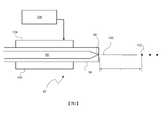
圖1說明包括具有LPP EUV光輻射器之EUV光源20之設備10的具體實例。如所展示,EUV光源20可包括用於產生一列光脈衝並將該等光脈衝遞送至光源腔室26中之系統22。光脈衝可沿著一或多個光束路徑從系統22行進並進入至腔室26中以在輻照區域28處照射源材料14之液滴以產生EUV光輸出用於在曝露器件50中曝露基板52。FIG. 1 illustrates a specific example of an
適用於圖1中所展示之系統22的雷射可包括脈衝雷射器件,例如,脈衝氣體放電CO2雷射器件,其例如用DC或RF激勵產生9.3 μm或10.6 μm輻射,以相對高功率(例如,10 kW或較高)及高脈衝重複率(例如,50 kHz或更多)操作。在一種特定實施方案中,雷射可為軸流式RF泵浦CO2雷射,其具有帶有多級放大的振盪器-放大器組態(例如,主振盪器/功率放大器(MOPA)或功率振盪器/功率放大器(POPA)),且具有由Q開關振盪器以相對低能量及高重複率(例如能夠100 kHz操作)啟動的種子脈衝。來自振盪器的雷射脈衝然後可在到達輻照區域28之前經放大、塑形及/或聚焦。連續泵浦CO2放大器可用於雷射系統22。替代地,雷射可經組態為所謂的「自瞄準」雷射系統,其中液滴用作光學諧振腔之一個反射鏡。Lasers suitable for use in the system 22 shown in FIG. 1 may include pulsed laser devices, eg, pulsed gas dischargeCO2 laser devices, that generate 9.3 μm or 10.6 μm radiation, eg, with DC or RF excitation, at relatively high powers (eg, 10 kW or more) and high pulse repetition rate (eg, 50 kHz or more) operation. In one particular implementation, the laser may be an axial RF pumpedCO laser with an oscillator-amplifier configuration with multistage amplification (eg, a master oscillator/power amplifier (MOPA) or power Oscillator/Power Amplifier (POPA)) with a seed pulse started by a Q-switched oscillator at relatively low energy and high repetition rate (eg capable of 100 kHz operation). The laser pulses from the oscillator may then be amplified, shaped and/or focused before reaching the
取決於應用,其他類型的雷射亦可能為適合的,例如,以高功率及高脈衝重複率操作的準分子或分子氟雷射。其他合適實例包括固態雷射,例如具有光纖、棒、板或碟狀活性介質,其他雷射架構具有一或多個腔室,例如振盪器腔室及一或多個放大腔室(具有並聯或串聯的放大腔室)、主振盪器/功率振盪器(MOPO)配置、主振盪器/功率圓形放大器(MOPRA)配置,或為一或多個準分子或分子氟或CO2放大器或振盪器腔室接種之固態雷射。其他設計可為適合的。Depending on the application, other types of lasers may also be suitable, such as excimer or molecular fluorine lasers operating at high power and high pulse repetition rate. Other suitable examples include solid state lasers, such as with optical fibers, rods, plates, or disk-shaped active media, and other laser architectures with one or more chambers, such as an oscillator chamber and one or more amplification chambers (with parallel or Amplification chambers in series), Master Oscillator/Power Oscillator (MOPO) configuration, Master Oscillator/Power Circular Amplifier (MOPRA) configuration, or for one or more excimer or molecular fluorine orCO2 amplifiers or oscillators Solid state laser for chamber inoculation. Other designs may be suitable.
在一些情況下,源材料可首先由預脈衝輻照,且然後由主脈衝輻照。預脈衝及主脈衝種子可由單個振盪器或兩個單獨振盪器產生。在一些設定中,可使用一或多個共同放大器來放大預脈衝種子及主脈衝種子兩者。對於其他配置,可使用單獨放大器來放大預脈衝及主脈衝種子。In some cases, the source material may be irradiated first by the pre-pulse and then by the main pulse. The pre-pulse and main-pulse seeds can be generated by a single oscillator or by two separate oscillators. In some arrangements, one or more common amplifiers may be used to amplify both the pre-pulse seed and the main-pulse seed. For other configurations, separate amplifiers can be used to amplify the pre-pulse and main-pulse seeds.
系統22可包括光束調節單元,該光束調節單元具有一或多個用於光束調節的光學器件,諸如擴展、轉向及/或聚焦到達輻照部位28之光束。舉例而言,可提供並配置可包括一或多個反射鏡、稜鏡、透鏡等的轉向系統以將雷射焦點轉向至腔室26中之不同位置。轉向系統可包括第一平面鏡,其安裝在可在二維上獨立地移動第一鏡的傾斜致動器上;及第二平面鏡,其安裝在可在二維上獨立地移動第二鏡的傾斜致動器上。藉助此配置,轉向系統可在與光束傳播方向(光束軸)大體上正交的方向上可控地移動焦點。System 22 may include a beam conditioning unit having one or more optics for beam conditioning, such as expanding, steering, and/or focusing the beam reaching
如在圖1中進一步展示,EUV光源20亦可包括源材料遞送系統90,該源材料遞送系統包括液滴源92,例如,將源材料(諸如錫液滴)遞送至腔室26之內部至輻照區域或主焦點28,其中液滴將與來自系統22之光脈衝交互作用,最終產生電漿並產生EUV發射以在曝露器件50中曝露基板52,諸如塗覆抗蝕劑之晶圓。關於各種液滴施配器組態的更多細節可在例如以下美國專利中找到:在2011年1月18日發佈的標題為「Systems and Methods for Target Material Delivery in a Laser Produced Plasma EUV Light Source」的美國專利第7,872,245號,在2008年7月29日發佈的標題為「Method and Apparatus For EUV Plasma Source Target Delivery」的美國專利第7,405,416號,及在2008年5月13日發佈的標題為「LPP EUV Plasma Source Material Target Delivery System」的美國專利第7,372,056號,該等美國專利中之每一者的內容特此以全文引用的方式併入本文中。As further shown in FIG. 1 , the EUV
用於產生用於基板曝露的EUV光輸出之源材料可包括(但未必限於)包括錫、鋰、氙或其組合之一材料。EUV發射元素,例如錫、鋰、氙等,可呈液滴及/或容納在液滴內之固體顆粒的形式。舉例而言,元素錫可用作純錫;用作錫化合物(例如,SnBr4、SnBr2、SnH4);用作錫合金(例如,錫-鎵合金、錫-銦合金、錫-銦-鎵合金);或其組合。取決於所使用材料,可在各種溫度下將源材料呈現至輻照區域,包括室溫或接近室溫(例如,錫合金,SnBr4)、在升高溫度下(例如,純錫)或在低於室溫之溫度下(例如,SnH4),且在一些狀況下,可為相對揮發性,例如,SnBr4。The source material used to generate the EUV light output for substrate exposure can include, but is not necessarily limited to, a material including one of tin, lithium, xenon, or combinations thereof. EUV emitting elements, such as tin, lithium, xenon, etc., may be in the form of droplets and/or solid particles contained within the droplets. For example, elemental tin can be used as pure tin; as tin compounds (eg,SnBr4 ,SnBr2 ,SnH4 ); as tin alloys (eg, tin-gallium alloys, tin-indium alloys, tin-indium- gallium alloy); or a combination thereof. Depending on the material used, the source material can be presented to the irradiated region at various temperatures, including room temperature or near room temperature (eg, tin alloys,SnBr4 ), at elevated temperatures (eg, pure tin), or at At temperatures below room temperature (eg,SnH4 ), and in some cases, can be relatively volatile, eg,SnBr4 .
繼續參考圖1,設備10亦可包括EUV控制器60,其亦可包括驅動雷射控制系統65,該驅動雷射控制系統用於控制系統22中之器件以藉此產生光脈衝以遞送至腔室26中,及/或用於光學器件在控制系統22中之移動。該設備亦可包括液滴位置偵測系統,該液滴位置偵測系統可包括一或多個液滴成像器70,該等液滴成像器提供指示一或多個液滴例如相對於輻照區域28之位置的輸出。成像器70可將此輸出提供至液滴位置偵測回饋系統62,該液滴位置偵測回饋系統可例如計算液滴位置及軌跡,由此可例如在逐個液滴的基礎上或平均地計算液滴誤差。然後可將液滴誤差作為輸入提供至控制器60,該控制器可例如向系統22提供位置、方向及/或定時校正信號以控制雷射觸發定時及/或控制光學器件在系統22中之移動,例如,改變經遞送至腔室26中之輻照區域28之光脈衝之位置及/或焦度。亦針對EUV光源20,源材料遞送系統90可具有可回應於來自控制器60之信號(在一些實施方案中可包括上文所描述之液滴誤差,或自其導出的一些數量)操作的控制系統,以例如,修改釋放點、初始液滴流方向、液滴釋放定時及/或液滴調變以校正到達所要輻照區域28之液滴中之誤差。With continued reference to FIG. 1, the
繼續圖1,設備亦可包括光學器件30,諸如具有呈一扁長球面(亦即,圍繞其主軸旋轉之一橢圓形)的形式之一反射表面之近垂直入射收集器鏡,該反射表面具有帶有鉬及矽之交替層,且在一些狀況下具有一或多個高溫擴散障壁層、平滑層、封蓋層及/或蝕刻停止層之漸變多層塗層。圖1展示光學器件30可形成有孔徑以允許由系統22產生的光脈衝穿過並到達輻照區域28。如所展示,光學器件30可為例如扁長球面反射鏡,其具有在輻照區域28內或附近的第一焦點及在所謂中間區域40處的第二焦點,其中EUV光可從EUV光源20輸出並輸入至利用EUV光之曝露器件50,例如積體電路光微影工具。應瞭解,可使用其他光學器件代替扁長球面反射鏡來收集光並將光引導至中間位置,以便隨後利用EUV光遞送至器件。Continuing with FIG. 1, the apparatus may also include
可將緩衝氣體(諸如氫氣、氦氣、氬氣或其組合)引入至腔室26中、從其補充及/或移除。緩衝氣體可在電漿放電期間存在於腔室26中且可起到減慢電漿產生離子的作用以減少光學器件降級及/或增加電漿效率。替代地,磁場及/或電場(未展示)可單獨使用,或與緩衝氣體組合使用,以減少快離子損壞。A buffer gas, such as hydrogen, helium, argon, or a combination thereof, may be introduced into, replenished from, and/or removed from the
圖2以示意圖格式說明簡化的液滴源92之組件。如彼處所展示,液滴源92可包括毛細管94,其在壓力下保持流體96,例如熔融錫。毛細管可由諸如玻璃的材料製成。亦展示,毛細管94可形成有帶有端或孔口98的噴嘴,允許加壓流體96流過噴嘴端98,建立連續流100,其隨後分裂成複數個液滴。所展示之液滴源92進一步包括在流體中產生擾動的子系統,該子系統具有與流體96可操作地耦接之可電致動元件104及驅動可電致動元件104之信號產生器106。FIG. 2 illustrates the components of a
可電致動元件104在流體96中產生擾動,此產生具有不同初始速度之液滴,導致至少一些毗鄰液滴對在到達之輻照區域前聚結在一起。初始液滴與聚結液滴的比率可為二、三或更多,且在一些狀況下為數十、數百或更多。此僅為用於產生液滴的一個系統。很明顯,可使用其他系統,諸如例如在噴嘴孔口處產生個別液滴的系統,例如用於「按需液滴」模式,其中氣壓僅足以在噴嘴孔口處形成目標材料之液滴,但不足以形成射流。參見在2008年11月11日發佈且標題為「Method and Apparatus for EUV Plasma Source Target Delivery Target Material Handling」的美國專利第7,449,703號,其全部揭示內容特此以引用的方式併入本文中。The electrically
當目標材料96首先離開噴嘴端98時,目標材料呈速度擾動的穩定流100的形式。流分裂成一系列具有不同速度的微液滴。微液滴聚結成中等大小之液滴,稱為次聚結液滴,相對於彼此具有不同的速度。次聚結液滴聚結成具有所要最終大小之液滴102。聚結步驟的數目可變化。從噴嘴至液滴達到其最終聚結狀態的點的距離為聚結距離L。When the
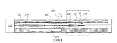
上述描述出於具體實例目的在特定類型的液滴產生器方面,以僅簡化描述。顯而易見,存在用於將諸如Sn的目標材料提供至噴嘴的其他配置,以及可使用且可有利地應用本文中的教示的其他調變手段。如所提及,滿足未來對高重複率的高EUV功率的需求將需要較高速度液滴及較大液滴間距。由液滴產生器產生之液滴的氣體加速已認為係增加液滴速度而不必增加驅動氣壓的方式。然而,氣體必須以不會同時將不可接受的不穩定性引入至液滴流中的方式引入至液滴加速器中。圖3A及圖3B展示設計成以可接受方式加速液滴的液滴產生器/加速器,其中圖3B為圖3A中虛線框中之部分的放大圖。圖3A及圖3B並非按比例繪製;液滴比所描繪的小得多,且經放大僅為了展示其位置及聚結狀態。The above description is in terms of specific types of droplet generators for specific example purposes only to simplify the description. Obviously, there are other configurations for providing target materials such as Sn to the nozzle, as well as other modulation means in which the teachings herein may be used and may be advantageously applied. As mentioned, meeting the future demand for high EUV power at high repetition rates will require higher velocity droplets and larger droplet spacing. Gas acceleration of droplets produced by droplet generators has been thought to be a way to increase droplet velocity without necessarily increasing the driving gas pressure. However, the gas must be introduced into the droplet accelerator in a manner that does not simultaneously introduce unacceptable instability into the droplet stream. Figures 3A and 3B show a droplet generator/accelerator designed to accelerate droplets in an acceptable manner, wherein Figure 3B is an enlarged view of the portion in the dashed box in Figure 3A. Figures 3A and 3B are not drawn to scale; the droplets are much smaller than depicted and are exaggerated only to show their location and coalesced state.
如在圖3A中所展示,液滴加速器200包括噴嘴端98下游的液滴聚結區210。用以加速液滴之氣體藉由入口230引入至液滴加速器200中。藉由建立液滴聚結區210之護罩220保護液滴聚結區210免受氣體影響。液滴聚結區210之流向長度(亦即,噴嘴端98與聚結區210之下游端之間的流向距離)經選擇使得液滴將在其離開液滴聚結區210之前完全聚結。換言之,液滴聚結區210之流向長度經選擇為大於聚結長度L。相反地,對於給定長度的液滴聚結區長度,可選擇驅動波形,使得聚結長度小於液滴聚結區之長度。保護液滴聚結區210內之液滴,尤其較小次聚結液滴及微液滴,降低不穩定性。此部分係因為較小液滴由於其質量較小而更容易橫向偏轉。As shown in FIG. 3A , the
亦如圖3A中所展示,氣體加速區240經組態為液滴聚結區210下游的液滴加速器200中之空腔。氣體加速區240的剖面面積(亦即,空腔之內部剖面)隨著距液滴聚結區210之下游端的流向距離而減小。氣體加速區240之剖面面積對於一些應用有利地製成弧形且甚至圓形。氣體加速區240之內部根據其他實施例的態樣經組態,使得氣體加速區240中之氣體之加速度為恆定的。然而,通常期望避免剖面中之任何銳邊並使表面具有空氣動力學特性。As also shown in FIG. 3A , the
氣體加速區240之剖面的減小導致氣體加速區240中之氣體加速。氣體夾帶液滴並在氣體加速區240中使其加速。氣體加速區之下游為孔口250。孔口250之下游為出口260。氣體加速區240為液滴開始其氣體驅動加速之區。然而,應注意,液滴在其離開氣體加速區240之後繼續加速。氣體加速區240主要係氣體加速之區。根據實施例的一個態樣,其為氣體正在加速的唯一區。在此氣體加速區240中,氣體加速並大體上平行於聚結液滴流流向流動以夾帶聚結液滴。在此上下文中,大體上平行意指足夠平行,使得氣流不會賦予液滴任何橫向於流向的顯著速度。圖3A中亦展示流動抑制元件280,其可為例如抑制器、撇渣器、消聲器、消音器或差動泵浦區域以管理離開加速器的高速氣體以限制其對存在於源容器中之其他流的影響,例如引入用於收集器保護及其他源材料管理的彼等流。The reduction in the cross-section of the
根據實施例的一個態樣,氣體在氣體加速區中之加速度經選擇為漸進以避免將不穩定性引入至液滴流中。此處「漸進」意指加速度使得氣體在氣體加速區240之長度內從約50 m/sec加速至約2000 m/sec,氣體加速區之長度通常在150毫米至約300毫米的範圍內。根據實施例的一個態樣,加速度經選擇使得氣體之速度不超過彼氣體在彼溫度下之聲速。根據實施例的一個態樣,加速度經選擇使得氣體之最終速度大約但小於,亦即幾乎但不完全為在彼溫度下彼氣體之聲速。根據實施例的另一態樣,氣體在其第一次在液滴聚結區210下游遇到液滴時之速度經選擇為大約等於液滴離開液滴聚結區210之速度。在此上下文下,大約等於意指足夠接近於液滴之速度,使得液滴在曝露於氣流時不會突然加速。對於其他實施例,氣體在其第一次在液滴聚結區210下游遇到液滴的情況下之速度經選擇為小於或大於液滴離開液滴聚結區210之速度。氣體加速區240之內部根據其他實施例的態樣經組態,使得氣體加速區240中之氣體之加速度為恆定的。According to one aspect of the embodiment, the acceleration of the gas in the gas acceleration region is selected to be gradual to avoid introducing instability into the droplet stream. "Progressive" here means that the acceleration causes the gas to accelerate from about 50 m/sec to about 2000 m/sec over the length of the
用於加速液滴的氣體通常應為具有低EUV吸收率的氣體。一種適合的氣體為H2。對於熟習此項技術者將顯而易見,可使用其他氣體及氣體混合物作為加速液滴的氣體。The gas used to accelerate the droplets should generally be a gas with low EUV absorption. A suitable gas isH2 . It will be apparent to those skilled in the art that other gases and gas mixtures may be used as droplet accelerating gases.
用於製造液滴聚結區310及氣體加速區240之內表面的材料有利地選擇為耐源材料(在此實例中為錫)腐蝕。適合的材料包括耐火金屬,諸如鉬、鎢、鉭、錸及其合金。表面亦可設置有塗層,諸如包括BN、TiN、SiC及CrN之陶瓷材料。若使用此類塗層,液滴加速器之下伏材料可為較習用合金,諸如不鏽鋼或類似材料。The materials used to fabricate the inner surfaces of the
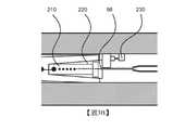
根據實施例的另一態樣,用於加速液滴的氣體在引入至氣體加速區340中之前經熱化。圖4展示用於實現上述情形的配置。在圖4中,管300經配置以從氣體供應器接收氣體。管300進入真空腔室26穿過凸緣320及腔室壁27,且然後經配置以通過液滴產生器310之主體。液滴產生器310將管300中之氣體加熱至液滴產生器310之內部溫度,因此藉由使氣體與液滴產生器310內部之溫度達到熱平衡來熱化氣體。經熱化氣體然後穿過入口340進入至液滴產生器310之加熱器區塊330中。通常,熱化結構經調適以將氣體加熱至200℃與300℃之間的溫度,但亦可使用其他合適的溫度。氣體從彼處輸送至一點,在該點處其經引入至氣體加速區240中。圖4中亦展示經設計以保護從凸緣320突出之高溫組件之籠罩350。當加速氣體進入氣體加速區中之真空時,其或多或少地絕熱膨脹。對於一些應用,藉由在氣體加速器中提供一或多個加熱器270來保持熱化為有利的,如在圖3A中所展示,以維持穩定的溫度。舉例而言,此穩定溫度可在200℃與300℃之間的範圍內。According to another aspect of the embodiment, the gas used to accelerate the droplets is thermalized before being introduced into the
上文已藉助於說明本發明之指定功能及關係之實施方案之功能建造區塊來描述本發明。為方便說明,本文中已任意界定此等功能建造區塊之界限。只要適當地執行本發明指定的功能及關係,就可以選擇合適的對象。The invention has been described above with the aid of functional building blocks that illustrate the implementation of the specified functions and relationships of the invention. For convenience of description, the boundaries of these functional building blocks have been arbitrarily defined herein. Appropriate objects can be selected so long as the functions and relationships specified by the invention are appropriately performed.
對具體實施例的前述描述將如此充分揭示本發明的一般性質,使得其他人可藉由應用此項技術內的知識,容易地修改及/或調適此類特定實施例的各種應用,無需過多的實驗,不脫離本發明的一般概念。因此,基於本文中呈現的教示及指導,此類調適及修改旨在處於所公開實施例的等效物的含義及範圍內。應理解,本文中之措辭或術語係出於描述而非限制的目的,使得本說明的術語或措辭將由熟習此項技術者鑒於教示及指導進行解釋。本發明之廣度及範疇不應受上文所闡述之例示性實施例中之任一者限制,而應僅根據隨附申請專利範圍及其等效內容來界定。The foregoing descriptions of specific embodiments will so sufficiently disclose the general nature of the invention that others, by applying knowledge within the art, can readily modify and/or adapt such specific embodiments for various applications without undue elaboration. Experiment without departing from the general concept of the invention. Therefore, such adaptations and modifications are intended to be within the meaning and range of equivalents of the disclosed embodiments, based on the teachings and guidance presented herein. It is to be understood that the phraseology or terminology herein is for the purpose of description and not limitation, such that the terminology or phraseology of this specification will be interpreted by one skilled in the art in light of the teaching and guidance. The breadth and scope of the present disclosure should not be limited by any of the exemplary embodiments set forth above, but should be defined only in accordance with the scope of the appended claims and their equivalents.
本發明之其他態樣在以下編號條項中闡述。1.一種用於產生EUV源材料之一液滴流的液滴產生器,該液滴產生器包含:一噴嘴,其經調適以從一噴嘴出口發出一液態EUV源材料流;一第一結構,其界定從該噴嘴出口向下游延伸至一第一位置的一液滴聚結區,其中該液態EUV源材料流分裂且聚結成液態EUV源材料之一聚結液滴流;至少一個入口,其經調適以連接至一氣體之一源;及一第二結構,其界定從該第一位置向下游延伸至一第二位置的一氣體加速區,與該至少一個入口進行流體連通,經配置以在該第一位置處接收該聚結液滴流,且經調適以致使將該氣體引入至在該第一位置下游的該氣體加速區中並加速且大體上平行於該聚結液滴流流向流動以夾帶該等聚結液滴,該液滴聚結區經配置且經組態使得該液滴聚結區中之液態EUV源材料不曝露於該氣體之一流向流動。2.如條項1之液滴產生器,其中該液滴聚結區之一流向長度在10 mm與200 mm之間。3.如條項2之液滴產生器,其中該氣體加速區之一流向長度在20 mm與200 mm之間。4.如條項1之液滴產生器,其中該氣體加速區具有一弧形剖面,該弧形剖面具有在該第一位置與該第二位置之間減小的一剖面面積。5.如條項1之液滴產生器,其中該氣體加速區具有一圓形剖面,該圓形剖面具有在該第一位置與該第二位置之間減小的一半徑。6.如條項1之液滴產生器,其中該氣體加速區經組態使得該氣體之一流向速度不超過該氣體之聲速。7.如條項1之液滴產生器,其中該氣體加速區經組態使得該氣體在該第二位置處之一流向速度大約但小於該氣體之聲速。8.如條項1之液滴產生器,其中該氣體加速區經組態使得該氣體在該第一位置處之一流向速度大約等於在該第一位置處離開該液滴聚結區之該等聚結液滴之一流向速度。9.如條項1之液滴產生器,其中該氣體加速該聚結液滴氣體,使得在該第一位置處進入該氣體加速區之聚結液滴在穿過該氣體加速區至該第二位置時從約80 m/sec加速至約130 m/sec。10.如條項1之液滴產生器,其進一步包含一熱化結構,該熱化結構經配置以與該氣體熱接觸且經調適以熱化該氣體以在將該氣體引入至該氣體加速區中之前與該液滴產生器達到熱平衡。11.如條項10之液滴產生器,其中該熱化結構經調適以將該氣體加熱至在200℃與300℃之間的一溫度。12.如條項10之液滴產生器,其中該液滴產生器進一步包含一源材料加熱器,該源材料加熱器經配置以向該液滴產生器中之該源材料供應熱,且該熱化結構經配置以在該源材料加熱器與該氣體之間轉移熱。13.如條項1之液滴產生器,其中該氣體為具有一低EUV吸收率的一氣體。14.如條項13之液滴產生器,其中該氣體包含氫氣。15.如條項1之液滴產生器,其中該第一結構及該第二結構中之至少一者包含一耐火金屬。16.如條項15之液滴產生器,其中該第一結構及該第二結構中之該至少一者包含鉬、鎢、鉭、錸,或鉬、鎢、鉭或錸之一合金。17.如條項1之液滴產生器,其中該第一結構及該第二結構中之該至少一者包含一氮化硼塗層。18.如條項1之液滴產生器,其進一步包含定位於該第二位置下游且經調適以管理離開該氣體加速區之高速氣體的一流量管理元件。19.一種加速EUV源材料液滴之方法,該方法包含:從一液滴產生器之一噴嘴出口發出一液態EUV源材料流;將該液態EUV源材料流轉化為界定從該噴嘴出口向下游延伸至一第一位置的一液滴聚結區之一第一結構中之一聚結液滴流;將在該第一位置處之該聚結液滴流引入至界定從該第一位置向下游延伸至一第二位置的一氣體加速區之一第二結構中;將一氣流引入至該氣體加速區中以大體上平行於該聚結液滴流流向流動;隨著該氣體接近該第二位置,在該氣體加速區中加速該氣流;及在該氣流中夾帶該等聚結液滴以加速該等聚結液滴,該液滴聚結區經配置且經組態使得該液滴聚結區中之液態EUV源材料不曝露於該氣體之一流向流動。20.如條項19之方法,其中該液滴聚結區之一流向長度在10 mm與200 mm之間。21.如條項19之方法,其中該液滴聚結區之一流向長度在20 mm與100 mm之間。22.如條項19之方法,其中該氣體加速區具有一弧形剖面,該弧形剖面具有在該第一位置與該第二位置之間減小的一剖面面積。23.如條項22之方法,其中該氣體加速區具有一圓形剖面,該圓形剖面具有在該第一位置與該第二位置之間減小的一半徑。24.如條項19之方法,其中在該氣體加速區中加速該氣流包含加速該氣體,使得該氣體之一流向速度不超過該氣體之聲速。25.如條項19之方法,其中在該氣體加速區中加速該氣流包含加速該氣體,使得該氣體在該第二位置處之一流向速度大約但小於該氣體之聲速。26.如條項19之方法,其中將一氣流引入至該氣體加速區中包含引入該氣體,使得該氣體在該第一位置處之一流向速度大約等於在該第一位置處離開該液滴聚結區之該等聚結液滴之一流向速度。27.如條項19之方法,其中在該氣流中夾帶該等聚結液滴以加速該等聚結液滴會加速該聚結液滴氣體,使得在該第一位置處進入該氣體加速區之聚結液滴在穿過該氣體加速區時在該第二位置處從約80 m/sec加速至約130 m/sec。28.如條項19之方法,其進一步包含熱化該氣體以在將該氣體引入至該氣體加速區中之前與該液滴產生器達到熱平衡。29.如條項19之方法,其中熱化該氣體包含將該氣體加熱至在200℃與300℃之間的一溫度。30.如條項19之方法,其中該液滴產生器包含一源材料加熱器,該源材料加熱器經配置以向該液滴產生器中之該源材料供應熱,且熱化該氣體包含在該源材料加熱器與該氣體之間轉移熱。31.如條項19之方法,其中該氣體具有一低EUV吸收率。32.如條項19之方法,其中該氣體包含氫氣。33.如條項19之方法,其中該第一結構及該第二結構中之至少一者包含一耐火金屬。34.如條項33之方法,其中該第一結構及該第二結構中之該至少一者包含鉬、鎢、鉭及錸中之至少一者。35.如條項19之方法,其中該第一結構及該第二結構中之該至少一者包含一氮化硼塗層。36.一種用於產生EUV源材料之一液滴流的液滴產生器,該液滴產生器包含:一噴嘴,其經調適以從一噴嘴出口發出液態EUV源材料;至少一個入口,其經調適以連接至一氣體之一源;一第一結構,其界定從該噴嘴出口向下游延伸至一第一位置的一第一區,其中由該噴嘴發出之該液態EUV源材料未曝露於該氣體之一流動,該EUV源材料在該第一位置處呈一液滴流形式;及一第二結構,其界定從該第一位置向下游延伸至一第二位置的一氣體加速區,與該入口進行流體連通,經配置以在該第一位置處接收該液滴流,且經調適以致使將該氣體引入至在該第一位置下游的該氣體加速區中並加速且大體上平行於該液滴流流向流動以夾帶該等液滴。37.如條項36之液滴產生器,其進一步包含定位於該第二位置下游並經調適以管理離開該氣體加速區之高速氣體的一流量管理元件。38.一種加速EUV源材料液滴之方法,該方法包含:從一液滴產生器之一噴嘴出口發出液態EUV源材料;使該液態EUV源材料通過從該噴嘴出口向下游延伸至一第一位置的一第一區;該液態EUV源材料作為一液滴流離開該第一區;將在該第一位置處之該液滴流引入至從該第一位置向下游延伸至一第二位置的一氣體加速區中;將一氣流引入至該氣體加速區中以大體上平行於該液滴流流向流動;隨著該氣體接近該第二位置,在該氣體加速區中加速該氣流;及在該氣流中夾帶該等液滴以加速該等液滴,該第一區經配置且經組態使得該第一區中之液態EUV源材料不曝露於該氣體之一流向流動。Other aspects of the invention are set forth in the numbered clauses below.1. A droplet generator for generating a stream of droplets of one of EUV source materials, the droplet generator comprising:a nozzle adapted to emit a stream of liquid EUV source material from a nozzle outlet;a first structure defining a droplet coalescence zone extending downstream from the nozzle outlet to a first location, wherein the stream of liquid EUV source material breaks up and coalesces into a coalesced droplet stream of liquid EUV source material;at least one inlet adapted to connect to a source of a gas; andA second structure defining a gas acceleration region extending downstream from the first location to a second location, in fluid communication with the at least one inlet, configured to receive the coalesced droplet at the first location flow, and adapted such that the gas is introduced into the gas acceleration zone downstream of the first location and accelerated and flowed substantially parallel to the flow direction of the coalesced droplets to entrain the coalesced droplets,The droplet coalescence zone is configured and configured such that the liquid EUV source material in the droplet coalescence zone is not exposed to one of the gas flow.2. The droplet generator of
其他實施方案在申請專利範圍之範疇內。Other embodiments are within the scope of the claims.
10:設備14:源材料20:EUV光源22:系統26:光源腔室/真空腔室27:腔室壁28:輻照區域40:中間區域50:曝露器件52:基板60:EUV控制器62:液滴位置偵測回饋系統65:驅動雷射控制系統70:液滴成像器90:源材料遞送系統92:液滴源94:毛細管96:流體98:噴嘴端/孔口100:流102:液滴104:可電致動元件106:信號產生器200:液滴加速器210:液滴聚結區220:護罩230:入口240:氣體加速區250:孔口260:出口270:加熱器280:流動抑制元件300:管310:液滴聚結區320:凸緣330:加熱器區塊340:氣體加速區350:籠罩L:聚結長度/聚結距離10: Equipment14: Source Materials20: EUV light source22: System26: Light source chamber/vacuum chamber27: Chamber Wall28: Irradiation area40: Middle area50: Expose the device52: Substrate60: EUV controller62: Droplet position detection feedback system65: Drive the laser control system70: Droplet Imager90: Source Material Delivery System92: Droplet Source94: capillary96: Fluid98: Nozzle end/orifice100: Stream102: Droplets104: Electrically Actuatable Elements106: Signal Generator200: Droplet Accelerator210: Droplet coalescence zone220: Shield230: Entrance240: Gas acceleration zone250: Orifice260:Export270: Heater280: Flow suppression element300: Tube310: Droplet coalescence zone320: Flange330: Heater block340: Gas acceleration zone350: ShroudedL: coalescence length/coalescence distance
併入本文中並形成說明書的一部分的附圖藉由實例而非藉由限制說明本發明之實施例之方法及系統。與詳細描述一起,附圖進一步用於解釋相關技術的原理且使得熟習此項技術者能夠製造及使用本文中所呈現之方法及系統。圖式特徵不一定按比例繪製。在圖式中,相似元件符號指示相同、功能上類似元件。The accompanying drawings, which are incorporated herein and form a part of the specification, illustrate by way of example and not by way of limitation the methods and systems of embodiments of the present invention. Together with the detailed description, the drawings further serve to explain the principles of the related art and to enable those skilled in the art to make and use the methods and systems presented herein. Schematic features are not necessarily drawn to scale. In the drawings, like reference numerals indicate identical, functionally similar elements.
圖1為包括具有LPP EUV光輻射器之EUV光源之設備的簡化示意圖。Figure 1 is a simplified schematic diagram of an apparatus including an EUV light source with an LPP EUV light emitter.
圖2為說明液滴流中之聚結狀態的液滴產生器的未按比例繪製的剖面圖。Figure 2 is a cross-sectional, not-to-scale, view of a droplet generator illustrating a coalescence state in a droplet stream.
圖3A為根據實施例的態樣的具有液滴加速器的液滴產生系統的未按比例繪製的剖面圖。3A is a not-to-scale cross-sectional view of a droplet generation system with a droplet accelerator according to an aspect of an embodiment.
圖3B為圖3A的一部分的放大圖。3B is an enlarged view of a portion of FIG. 3A.
圖4為根據實施例的態樣的具有液滴加速器的液滴產生系統的平面圖。4 is a plan view of a droplet generation system with a droplet accelerator according to an aspect of an embodiment.
本發明的進一步特徵及優點,以及本發明之各種實施例的結構及操作,將在下文面參考附圖進行詳細描述。應注意,本發明並不限於本文中所闡述之特定實施例。此等實施例僅出於說明性目的而呈現於本文中。基於本文中所含有之教示,額外實施例對於熟習相關技術者將為顯而易見的。Further features and advantages of the present invention, as well as the structure and operation of various embodiments of the present invention, will be described in detail below with reference to the accompanying drawings. It should be noted that the present invention is not limited to the specific embodiments set forth herein. Such embodiments are presented herein for illustrative purposes only. Additional embodiments will be apparent to those skilled in the relevant art based on the teachings contained herein.
98:噴嘴端/孔口98: Nozzle end/orifice
210:液滴聚結區210: Droplet coalescence zone
220:護罩220: Shield
230:入口230: Entrance
Claims (38)
Translated fromChineseApplications Claiming Priority (2)
| Application Number | Priority Date | Filing Date | Title |
|---|---|---|---|
| US202063045354P | 2020-06-29 | 2020-06-29 | |
| US63/045,354 | 2020-06-29 |
Publications (1)
| Publication Number | Publication Date |
|---|---|
| TW202209933Atrue TW202209933A (en) | 2022-03-01 |
Family
ID=76708209
Family Applications (1)
| Application Number | Title | Priority Date | Filing Date |
|---|---|---|---|
| TW110121110ATW202209933A (en) | 2020-06-29 | 2021-06-10 | Apparatus for and method of accelerating droplets in a droplet generator for an euv source |
Country Status (5)
| Country | Link |
|---|---|
| US (1) | US20230164900A1 (en) |
| KR (1) | KR20230027099A (en) |
| CN (1) | CN115918265A (en) |
| TW (1) | TW202209933A (en) |
| WO (1) | WO2022002662A1 (en) |
Families Citing this family (2)
| Publication number | Priority date | Publication date | Assignee | Title |
|---|---|---|---|---|
| CN120304016A (en) | 2022-12-09 | 2025-07-11 | Asml荷兰有限公司 | Controlled droplet generator nozzle environment for increased reliability |
| DE102023112715B3 (en) | 2023-05-15 | 2024-08-22 | Fraunhofer-Gesellschaft zur Förderung der angewandten Forschung eingetragener Verein | Method for producing a nozzle unit for wafer production and nozzle unit |
Family Cites Families (7)
| Publication number | Priority date | Publication date | Assignee | Title |
|---|---|---|---|---|
| US7405416B2 (en) | 2005-02-25 | 2008-07-29 | Cymer, Inc. | Method and apparatus for EUV plasma source target delivery |
| US7372056B2 (en) | 2005-06-29 | 2008-05-13 | Cymer, Inc. | LPP EUV plasma source material target delivery system |
| US7449703B2 (en) | 2005-02-25 | 2008-11-11 | Cymer, Inc. | Method and apparatus for EUV plasma source target delivery target material handling |
| US7872245B2 (en) | 2008-03-17 | 2011-01-18 | Cymer, Inc. | Systems and methods for target material delivery in a laser produced plasma EUV light source |
| US8598551B2 (en) | 2010-01-07 | 2013-12-03 | Asml Netherlands B.V. | EUV radiation source comprising a droplet accelerator and lithographic apparatus |
| JP6751163B2 (en)* | 2017-01-30 | 2020-09-02 | ギガフォトン株式会社 | Extreme ultraviolet light generator |
| US11134558B2 (en)* | 2018-09-28 | 2021-09-28 | Taiwan Semiconductor Manufacturing Co., Ltd. | Droplet generator assembly and method for using the same and radiation source apparatus |
- 2021
- 2021-06-10TWTW110121110Apatent/TW202209933A/enunknown
- 2021-06-21USUS18/011,593patent/US20230164900A1/enactivePending
- 2021-06-21CNCN202180046047.XApatent/CN115918265A/enactivePending
- 2021-06-21WOPCT/EP2021/066798patent/WO2022002662A1/ennot_activeCeased
- 2021-06-21KRKR1020227046339Apatent/KR20230027099A/enactivePending
Also Published As
| Publication number | Publication date |
|---|---|
| CN115918265A (en) | 2023-04-04 |
| WO2022002662A1 (en) | 2022-01-06 |
| KR20230027099A (en) | 2023-02-27 |
| US20230164900A1 (en) | 2023-05-25 |
Similar Documents
| Publication | Publication Date | Title |
|---|---|---|
| TWI821231B (en) | Apparatus for and method of controlling coalescence of droplets in a droplet stream | |
| US9516730B2 (en) | Systems and methods for buffer gas flow stabilization in a laser produced plasma light source | |
| JP6784737B2 (en) | Equipment and methods for delivering source material in laser-generated plasma EUV light sources | |
| US20100258748A1 (en) | System, method and apparatus for droplet catcher for prevention of backsplash in a euv generation chamber | |
| US10681795B2 (en) | Apparatus for and method of source material delivery in a laser produced plasma EUV light source | |
| US9066412B2 (en) | Systems and methods for cooling an optic | |
| TW202209933A (en) | Apparatus for and method of accelerating droplets in a droplet generator for an euv source | |
| US20240292510A1 (en) | Apparatus and method for producing droplets of target material in an euv source | |
| KR102759799B1 (en) | Device and method for controlling introduction of EUV target material into an EUV chamber |