TW202209403A - Gas flow regulation device and regulation method and plasma processing device wherein the gas flow regulation device comprises a gas baffle and multiple liftable isolation assemblies arranged on the gas baffle - Google Patents
Gas flow regulation device and regulation method and plasma processing device wherein the gas flow regulation device comprises a gas baffle and multiple liftable isolation assemblies arranged on the gas baffleDownload PDFInfo
- Publication number
- TW202209403A TW202209403ATW110122197ATW110122197ATW202209403ATW 202209403 ATW202209403 ATW 202209403ATW 110122197 ATW110122197 ATW 110122197ATW 110122197 ATW110122197 ATW 110122197ATW 202209403 ATW202209403 ATW 202209403A
- Authority
- TW
- Taiwan
- Prior art keywords
- gas
- annular
- baffle
- gas flow
- gas distribution
- Prior art date
Links
- 238000002955isolationMethods0.000titleclaimsabstractdescription58
- 238000012545processingMethods0.000titleclaimsabstractdescription46
- 238000000034methodMethods0.000titleclaimsabstractdescription28
- 238000000429assemblyMethods0.000titleabstractdescription4
- 230000000712assemblyEffects0.000titleabstractdescription4
- 238000009826distributionMethods0.000claimsabstractdescription140
- 239000000758substrateSubstances0.000claimsabstractdescription60
- 238000005192partitionMethods0.000claimsdescription64
- 238000007789sealingMethods0.000claimsdescription64
- 230000001105regulatory effectEffects0.000claimsdescription40
- 125000006850spacer groupChemical group0.000claimsdescription24
- 238000006243chemical reactionMethods0.000claimsdescription16
- 230000008859changeEffects0.000claimsdescription7
- 230000013011matingEffects0.000claims2
- 230000008569processEffects0.000abstractdescription18
- 239000000126substanceSubstances0.000abstractdescription18
- 230000035945sensitivityEffects0.000abstractdescription5
- 238000012360testing methodMethods0.000abstractdescription4
- 230000002708enhancing effectEffects0.000abstract1
- 239000007789gasSubstances0.000description283
- 238000009832plasma treatmentMethods0.000description14
- 239000012495reaction gasSubstances0.000description7
- 238000010586diagramMethods0.000description6
- 230000004888barrier functionEffects0.000description3
- 238000009434installationMethods0.000description3
- 238000004891communicationMethods0.000description2
- 238000005260corrosionMethods0.000description2
- 230000007797corrosionEffects0.000description2
- 238000005516engineering processMethods0.000description2
- 238000005530etchingMethods0.000description2
- 230000006872improvementEffects0.000description2
- 238000000151depositionMethods0.000description1
- 230000008021depositionEffects0.000description1
- 230000000694effectsEffects0.000description1
- 238000004519manufacturing processMethods0.000description1
- 238000012986modificationMethods0.000description1
- 230000004048modificationEffects0.000description1
- NJPPVKZQTLUDBO-UHFFFAOYSA-NnovaluronChemical compoundC1=C(Cl)C(OC(F)(F)C(OC(F)(F)F)F)=CC=C1NC(=O)NC(=O)C1=C(F)C=CC=C1FNJPPVKZQTLUDBO-UHFFFAOYSA-N0.000description1
- 238000005498polishingMethods0.000description1
- 239000000376reactantSubstances0.000description1
- 238000012827research and developmentMethods0.000description1
- 230000000630rising effectEffects0.000description1
- 239000004065semiconductorSubstances0.000description1
- 238000006467substitution reactionMethods0.000description1
- 238000000427thin-film depositionMethods0.000description1
Images


Classifications
- H—ELECTRICITY
- H01—ELECTRIC ELEMENTS
- H01J—ELECTRIC DISCHARGE TUBES OR DISCHARGE LAMPS
- H01J37/00—Discharge tubes with provision for introducing objects or material to be exposed to the discharge, e.g. for the purpose of examination or processing thereof
- H01J37/32—Gas-filled discharge tubes
- H01J37/32431—Constructional details of the reactor
- H01J37/3244—Gas supply means
- H01J37/32449—Gas control, e.g. control of the gas flow
Landscapes
- Physics & Mathematics (AREA)
- Engineering & Computer Science (AREA)
- Plasma & Fusion (AREA)
- Chemical & Material Sciences (AREA)
- Analytical Chemistry (AREA)
- Drying Of Semiconductors (AREA)
- Endoscopes (AREA)
- Encapsulation Of And Coatings For Semiconductor Or Solid State Devices (AREA)
- Plasma Technology (AREA)
Abstract
Description
Translated fromChinese本發明涉及半導體製造領域,尤其涉及一種氣體流量調節裝置,氣體流量調節方法,及應用該氣體流量調節裝置的等離子體處理裝置。The invention relates to the field of semiconductor manufacturing, in particular to a gas flow regulating device, a gas flow regulating method, and a plasma processing device using the gas flow regulating device.
隨著晶片行業的日益更新,技術節點的日趨提升,對製程和技術的精雕細琢也有著越來越高的要求,尤其是到了3nm以下,精細化製程就日趨突出,例如製程的均一性,即任何薄膜的沉積,蝕刻,拋光等製程隨著奈米節點的提升都需要很高的均一性。With the increasing update of the chip industry and the improvement of technology nodes, there are also higher and higher requirements for the meticulous crafting of processes and technologies, especially below 3nm, the refined process becomes more and more prominent, such as the uniformity of the process, That is to say, any thin film deposition, etching, polishing and other processes require high uniformity with the improvement of nano-nodes.
現階段的製程研發過程中,在一些新的化學環境抑或是對現有的化學環境進行進一步優化時,常常面臨許多困難,其一便是均一性的調節。目前有較多的方法來進行均一性的調節,其中一個方法就是通過氣體擋板(gas buffer)來調節進入氣體噴淋頭的氣體流量,氣體擋板通過安裝基座(mounting base)安裝至氣體噴淋頭(showerhead)上方,氣體擋板連接外部反應氣體,氣體擋板一般可分為多個區域,每個區域都是相互隔離的,通過調節進入每個區域的氣體比例來獲得不同區域的氣體含量,進而改變安裝基座至氣體噴淋頭不同區域最後至製程腔體(chamber)的氣體含量,從而來提高均一蝕刻或者沉積的效果。由於現有的氣體擋板中的各個區域的位置和面積大小都是固定不變的,某一種氣體擋板中的氣體分區可能僅僅適用於某一種反應的化學氣體,而不同的製程需要使用不同的化學反應氣體,不同的化學氣體具有不同的密度,同一個氣體擋板無法同時滿足在不同的化學氣體環境下的均一性調節要求,降低了氣體擋板在不同的氣體,不同的氣體比例,不同的化學環境中的靈敏度,不利於工藝製程的進行,降低了産品的良率。In the process of process research and development at the current stage, many difficulties are often faced in some new chemical environments or when further optimizing the existing chemical environments. One of them is the adjustment of uniformity. At present, there are many methods to adjust the uniformity. One of the methods is to adjust the gas flow rate entering the gas shower head through a gas buffer. The gas baffle is installed to the gas through a mounting base. Above the showerhead, the gas baffle is connected to the external reaction gas. The gas baffle can generally be divided into multiple areas, and each area is isolated from each other. Gas content, and then change the gas content from the mounting base to different areas of the gas shower head and finally to the process chamber, so as to improve the effect of uniform etching or deposition. Since the position and size of each area in the existing gas baffle are fixed, the gas partition in a certain gas baffle may only be suitable for a certain chemical gas, and different processes need to use different Chemical reaction gas, different chemical gases have different densities, the same gas baffle cannot meet the uniformity adjustment requirements in different chemical gas environments at the same time, reducing the gas baffle in different gases, different gas ratios, different The sensitivity in the chemical environment is not conducive to the progress of the process and reduces the yield of the product.
這裡的陳述僅提供與本發明有關的背景技術,而並不必然地構成現有技術。The statements herein merely provide background related to the present invention and do not necessarily constitute prior art.
本發明提供一種氣體流量調節裝置和調節方法及等離子體處理裝置,根據等離子體處理速率的變化,實現對氣體擋板與安裝基板之間的圓形氣體分配區域和環形氣體分配區域的面積進行動態調節,從而動態地調節等離子體處理裝置內氣體擋板中的氣體腔分布,獲得均勻的等離子體處理速率。The present invention provides a gas flow regulating device, regulating method and plasma processing device, which can dynamically adjust the area of the circular gas distribution area and the annular gas distribution area between the gas baffle and the mounting substrate according to the change of the plasma processing rate. adjustment, thereby dynamically adjusting the distribution of the gas cavity in the gas baffle in the plasma processing device to obtain a uniform plasma processing rate.
為了達到上述目的,本發明提供一種氣體流量調節裝置,其設置在等離子體處理裝置的一真空反應腔內,所述氣體流量調節裝置與一外部供氣裝置連接,所述氣體流量調節裝置通過安裝基板實現對氣體噴淋頭的不同區域的面積進行調節,所述氣體流量調節裝置包含:In order to achieve the above object, the present invention provides a gas flow regulating device, which is arranged in a vacuum reaction chamber of a plasma processing device, the gas flow regulating device is connected with an external gas supply device, and the gas flow regulating device is installed by The substrate realizes the adjustment of the areas of different regions of the gas shower head, and the gas flow adjustment device includes:
氣體擋板,包含相對設置的頂板和底板,所述底板與安裝基板配合形成同心設置的圓形氣體分配區域和至少一環形氣體分配區域;a gas baffle, comprising a top plate and a bottom plate arranged oppositely, and the bottom plate cooperates with the mounting substrate to form a concentrically arranged circular gas distribution area and at least one annular gas distribution area;
隔離組件,可升降地設置於所述氣體擋板與安裝基板之間,用於對所述圓形氣體分配區域和/或所述環形氣體分配區域的面積進行調節。The isolation component is movably arranged between the gas baffle and the mounting substrate, and is used for adjusting the area of the circular gas distribution area and/or the annular gas distribution area.
所述隔離組件包含至少兩層同心設置的環狀隔離層,升降不同的環狀隔離層可以改變所述圓形氣體分配區域和/或所述環形氣體分配區域的面積。The isolation assembly includes at least two concentrically arranged annular isolation layers, and lifting and lowering different annular isolation layers can change the area of the circular gas distribution area and/or the annular gas distribution area.
一方面,所述環狀隔離層包含一環狀隔板,所述環狀隔板為可升降活動連接。In one aspect, the annular isolation layer includes an annular baffle, and the annular baffle is a movable connection that can be raised and lowered.
所述環狀隔離層還包含設置在所述氣體擋板的頂板上的升降固定組件,所述升降固定組件連接所述環狀隔板,實現所述環狀隔板的升降。The annular isolation layer further includes a lifting and fixing assembly arranged on the top plate of the gas baffle, and the lifting and fixing assembly is connected with the annular baffle to realize the lifting and lowering of the annular baffle.
所述環狀隔板與所述安裝基板接觸的一端設置有第一密封圈,用於實現所述環狀隔板與所述安裝基板之間的密封。One end of the annular spacer in contact with the mounting substrate is provided with a first sealing ring, which is used to achieve sealing between the annular spacer and the mounting substrate.
所述環狀隔板上設置有第二密封圈,所述第二密封圈位於所述氣體擋板的底板上方,所述第二密封圈用於實現所述環狀隔板與所述氣體擋板的底板之間的密封。A second sealing ring is arranged on the annular baffle, the second sealing ring is located above the bottom plate of the gas baffle, and the second sealing ring is used to realize the annular baffle and the gas baffle Seal between the bottom plates of the plates.
所述氣體擋板的底板上具有通孔,所述環狀隔板降下時穿過所述通孔與所述安裝基板接觸。The bottom plate of the gas baffle is provided with a through hole, and the annular partition plate passes through the through hole and contacts the mounting substrate when it is lowered.
所述通孔的形狀與所述第二密封圈的形狀相互契合,隨著所述環狀隔板下降,所述第二密封圈可以與所述通孔完全匹配貼合密封在一起,避免所述氣體擋板內的氣體經過所述通孔進入相鄰區域。The shape of the through hole and the shape of the second sealing ring match each other, and as the annular baffle descends, the second sealing ring can be completely matched and sealed with the through hole, avoiding any problems. The gas in the gas baffle enters the adjacent area through the through hole.
所述氣體擋板還包含連接組件,所述連接組件的一端連接所述氣體擋板的頂板,所述連接組件的另一端連接所述氣體擋板的底板,用以支撑所述氣體擋板的底板並維持所述通孔的形狀。The gas baffle further includes a connecting assembly, one end of the connecting assembly is connected to the top plate of the gas baffle, and the other end of the connecting assembly is connected to the bottom plate of the gas baffle to support the gas baffle. bottom plate and maintain the shape of the through hole.
另一方面,所述環狀隔離層包含沿圓周線間隔設置的至少兩個柱狀隔板,以及設置在相鄰的柱狀隔板之間的扇環狀隔板,所述柱狀隔板可升降活動連接,所述扇環狀隔板固定設置。On the other hand, the annular isolation layer includes at least two columnar partitions arranged at intervals along the circumference, and a fan-shaped partition arranged between adjacent columnar partitions, the columnar partitions It can be moved up and down, and the fan annular partition is fixedly arranged.
所述環狀隔離層還包含設置在所述氣體擋板的頂板上的升降固定組件,所述升降固定組件連接所述柱狀隔板,實現所述柱狀隔板的升降。The annular isolation layer further includes a lifting and fixing assembly arranged on the top plate of the gas baffle, and the lifting and fixing assembly is connected to the columnar separator to realize the lifting and lowering of the columnar separator.
所述柱狀隔板與所述安裝基板接觸的一端設置有第一密封圈,用於實現所述柱狀隔板與所述安裝基板之間的密封。A first sealing ring is provided at one end of the columnar spacer in contact with the mounting substrate, which is used to achieve sealing between the columnar spacer and the mounting substrate.
所述柱狀隔板上設置有第二密封圈,所述第二密封圈位於所述氣體擋板的底板上方,所述第二密封圈用於實現所述柱狀隔板與所述氣體擋板的底板之間的密封。A second sealing ring is provided on the cylindrical separator, the second sealing ring is located above the bottom plate of the gas baffle, and the second sealing ring is used to realize the cylindrical separator and the gas barrier Seal between the bottom plates of the plates.
所述柱狀隔板上設置有第三密封圈,用於實現所述柱狀隔板與所述扇環狀隔板之間的密封。A third sealing ring is arranged on the columnar partition, which is used to realize the sealing between the columnar partition and the fan-shaped partition.
所述氣體擋板的底板上具有通孔,所述柱狀隔板穿過所述通孔與所述安裝基板接觸。The bottom plate of the gas baffle is provided with a through hole, and the column spacer passes through the through hole and is in contact with the mounting substrate.
所述通孔的形狀與所述第二密封圈的形狀相互契合,隨著所述柱狀隔板下降,所述第二密封圈可以與所述通孔完全匹配貼合密封在一起,避免所述氣體擋板內的氣體經過所述通孔進入相鄰區域。The shape of the through hole and the shape of the second sealing ring fit each other, and as the columnar partition descends, the second sealing ring can be completely matched and sealed with the through hole, so as to avoid any problems. The gas in the gas baffle enters the adjacent area through the through hole.
所述升降固定組件包含螺紋連接的螺桿和螺母,所述螺桿固定連接所述環狀隔板或柱狀隔板,通過螺母的旋轉實現螺桿的升降,從而實現環狀隔板或柱狀隔板的升降。The lifting and fixing assembly includes a screw and a nut that are threadedly connected, the screw is fixedly connected to the annular partition or the columnar partition, and the rotation of the nut realizes the lifting of the screw, thereby realizing the annular partition or the columnar partition. the lift.
所述螺桿上設置有波紋管,用於實現所述升降固定組件與所述氣體擋板的頂板之間的密封。The screw is provided with a bellows for realizing the sealing between the lifting and fixing assembly and the top plate of the gas baffle.
所述氣體擋板的底板上設置多個氣體通孔,用於實現對所述圓形氣體分配區域和環形氣體分配區域的氣體輸送。A plurality of gas through holes are arranged on the bottom plate of the gas baffle, so as to realize the gas delivery to the circular gas distribution area and the annular gas distribution area.
所述安裝基板上設置多個氣體通孔,所述氣體通孔與所述氣體噴淋頭上的氣體通孔相對應。A plurality of gas through holes are provided on the mounting substrate, and the gas through holes correspond to the gas through holes on the gas shower head.
本發明還提供一種等離子體處理裝置,包含一真空反應腔,所述真空反應腔內設置一用於支撑基片的基座,所述真空反應腔內還設置一氣體噴淋頭,所述氣體噴淋頭設置在安裝基板上,所述安裝基板與所述一氣體流量調節裝置配合,實現對所述氣體噴淋頭不同區域的面積進行調節。The present invention also provides a plasma processing device, comprising a vacuum reaction chamber, a base for supporting a substrate is arranged in the vacuum reaction chamber, and a gas shower head is also arranged in the vacuum reaction chamber, and the gas The shower head is arranged on an installation substrate, and the installation substrate cooperates with the gas flow adjustment device to realize the adjustment of the areas of different regions of the gas shower head.
本發明還提供一種採用所述氣體流量調節裝置實現的等離子體處理裝置內的氣體流量調節方法,選定與等離子體處理速率不均勻區域對應的圓形氣體分配區域和/或環形氣體分配區域的範圍,通過調節所述環狀隔板的升降,或通過調節所述柱狀隔板的升降,實現對所述圓形氣體分配區域和/或所述環形氣體分配區域的面積進行動態調節,從而使該選定的圓形氣體分配區域和/或環形氣體分配區域對應的區域的等離子體處理速率與其他區域達到一致。The present invention also provides a gas flow adjustment method in a plasma processing device realized by using the gas flow adjustment device, and the range of the circular gas distribution area and/or the annular gas distribution area corresponding to the uneven plasma processing rate area is selected , by adjusting the lifting of the annular baffle, or by adjusting the lifting of the columnar baffle, the area of the circular gas distribution area and/or the annular gas distribution area can be dynamically adjusted, so that the The plasma processing rate of the region corresponding to the selected circular gas distribution region and/or annular gas distribution region is consistent with other regions.
所述選定的圓形氣體分配區域和/或環形氣體分配區域對應的區域的等離子體處理速率高於其他區域,則通過調節所述環狀隔板或柱狀隔板上升,以增加所述圓形氣體分配區域和/或所述環形氣體分配區域的面積。If the plasma processing rate of the selected circular gas distribution area and/or the area corresponding to the annular gas distribution area is higher than that of other areas, the annular spacer or columnar spacer can be adjusted to rise to increase the circular gas distribution. shape gas distribution area and/or the area of said annular gas distribution area.
所述選定的圓形氣體分配區域和/或環形氣體分配區域對應的區域的等離子體處理速率低於其他區域,則通過調節所述環狀隔板或柱狀隔板下降,以减少所述圓形氣體分配區域和/或所述環形氣體分配區域的面積。If the plasma processing rate of the selected circular gas distribution area and/or the area corresponding to the annular gas distribution area is lower than that of other areas, the annular spacer or columnar spacer is adjusted to descend to reduce the circular gas distribution. shape gas distribution area and/or the area of said annular gas distribution area.
本發明通過設置可升降的隔離組件,根據等離子體處理速率的變化,實現對氣體擋板與安裝基板之間的圓形氣體分配區域和環形氣體分配區域的面積進行動態調節,從而動態地調節等離子體處理裝置內氣體擋板中的氣體腔分布,可以適用於不同的化學氣體環境和不同的氣體比例,令不同的氣體分配區域面積對應不同的化學氣體環境和不同的氣體比例,大大提高了對等離子體處理速率進行調節的靈活性、靈敏度和準確性,提高了等離子體處理速率的均勻性,且操作簡單,提高了設備的適用度,縮短了製程調整試驗周期。The present invention dynamically adjusts the area of the circular gas distribution area and the annular gas distribution area between the gas baffle and the mounting substrate by setting the liftable isolation component according to the change of the plasma processing rate, so as to dynamically adjust the plasma The gas cavity distribution in the gas baffle in the body treatment device can be applied to different chemical gas environments and different gas ratios, so that different gas distribution areas correspond to different chemical gas environments and different gas ratios, which greatly improves the The flexibility, sensitivity and accuracy of the plasma treatment rate adjustment improve the uniformity of the plasma treatment rate, and the operation is simple, the applicability of the equipment is improved, and the process adjustment test period is shortened.
以下根據圖1~圖13,具體說明本發明的較佳實施例。Hereinafter, the preferred embodiments of the present invention will be described in detail with reference to FIGS. 1 to 13 .
如圖1所示,本發明提供一種等離子體處理裝置,包含一真空反應腔1,所述真空反應腔1內設置一作為下電極的基座7,基座7上設置靜電夾盤8,基片9設置在靜電夾盤8上。所述真空反應腔1內還設置一作為上電極的氣體噴淋頭5,所述氣體噴淋頭5設置在安裝基板4上,所述安裝基板4上設置多個氣體通孔41,所述安裝基板4上的氣體通孔41與所述氣體噴淋頭5上的氣體通孔51相對應。所述真空反應腔1內還設置一氣體流量調節裝置3,所述氣體流量調節裝置3通過所述安裝基板4連接所述氣體噴淋頭5,且所述氣體流量調節裝置3與一外部供氣裝置2連接。反應氣體從所述外部供氣裝置2進入所述氣體流量調節裝置3,所述安裝基板4與所述氣體流量調節裝置3配合,實現對所述氣體噴淋頭5的不同區域的面積進行調節,從而對所述氣體噴淋頭5的不同區域的氣體流量進行調節,進入真空反應腔1的反應氣體電離生成等離子體6,對基片9進行處理。As shown in FIG. 1 , the present invention provides a plasma processing device, which includes a
在本發明的一個實施例中,如圖2和圖3所示,所述氣體擋板31包含相對設置的頂板32和底板33,所述底板33與所述安裝基板4之間設置固定的環狀結構3303,用於將安裝基板4的進氣面分隔形成同心設置的圓形氣體分配區域301和至少一環形氣體分配區域302。由於所述環狀結構3303為固定結構,圓形氣體分配區域301和環形氣體分配區域302的面積相對固定,為了對氣體噴淋頭的不同氣體分配區域進行更為靈活的氣體流量調節,本發明提供的氣體流量調節裝置3包含氣體擋板31和設置在所述氣體擋板31上的多個隔離組件34,所述隔離組件34可升降地設置於所述氣體擋板31與安裝基板4之間,且所述隔離組件34可以對所述圓形氣體分配區域301和/或所述環形氣體分配區域302的面積進行動態調節,所述底板33上設置多個氣體通孔3302,用於實現對所述圓形氣體分配區域301和環形氣體分配區域302的氣體輸送。In an embodiment of the present invention, as shown in FIG. 2 and FIG. 3 , the
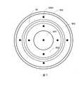
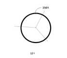
如圖4~圖6所示,所述隔離組件34包含至少兩層同心設置的環狀隔離層35,所述環狀隔離層35包含一環狀隔板3501和至少兩個升降固定組件3502,所述環狀隔板3501與所述頂板32和底板33為可升降活動連接,在本實施例中,設置了三層環狀隔離層35,每層所述環狀隔離層35上設置了六個升降固定組件3502(如圖5所示),所述升降固定組件3502包含螺紋連接的螺桿3506和螺母3507,所述螺桿3506固定連接所述環狀隔板3501,通過所述螺母3507的旋轉實現所述螺桿3506的升降,從而實現所述環狀隔板3501的升降,所述螺桿3506上設置有波紋管3505,用於實現所述升降固定組件3502與所述氣體擋板31的頂板32之間的密封。所述環狀隔板3501與所述安裝基板4接觸的一端設置有第一密封圈3503,用於實現所述環狀隔板3501與所述安裝基板4之間的密封。所述環狀隔板3501上設置有第二密封圈3504,所述第二密封圈3504位於所述氣體擋板31的底板33上方,所述第二密封圈3504用於實現所述環狀隔板3501與所述氣體擋板31的底板33之間的密封。所述第一密封圈3503和所述第二密封圈3504都具有耐高溫,耐腐蝕等特性。As shown in FIGS. 4 to 6 , the
如圖4所示,為了與所述的隔離組件34相匹配,所述氣體擋板31的底板33上設置有通孔3301,所述環狀隔板3501降下時穿過所述通孔3301與所述安裝基板4接觸,所述通孔3301的形狀與所述第二密封圈3504的形狀相互契合,隨著所述環狀隔板3501下降,所述第二密封圈3504可以與所述通孔3301完全匹配貼合密封在一起,避免所述氣體擋板31內的氣體經過所述通孔3301進入相鄰區域。由於本實施例中採用的是環狀隔板3501,因此從俯視圖中看,與其匹配的通孔3301也呈環狀,所述底板33上存在多個環狀的通孔3301會導致所述底板33被割裂為多個部分,為了防止相鄰的通孔3301之間的底板33脫落,則設置連接組件36,所述連接組件36的一端連接所述氣體擋板31的頂板32,所述連接組件36的另一端連接所述氣體擋板31的底板33,用以支撑所述氣體擋板31的底板33並維持所述通孔3301的形狀。As shown in FIG. 4 , in order to match with the
在等離子體處理過程中,由於不同製程中,參與反應的化學氣體的種類和比例不同,氣體噴淋頭上不同的氣體分配區域需要輸送的氣體流量等參數存在變化,因此需要通過升降所述隔離組件34中的所述環狀隔板3501來動態調節所述氣體擋板31與安裝基板4之間的所述圓形氣體分配區域和/或所述環形氣體分配區域的面積,從而動態調節所述氣體噴淋頭5的不同區域的氣體流量,獲得均勻的等離子體處理速率。In the process of plasma treatment, due to the different types and proportions of chemical gases involved in the reaction in different processes, the parameters such as the gas flow rate that need to be delivered in different gas distribution areas on the gas shower head vary, so it is necessary to lift and lower the isolation components. The
在本實施例中,所述底板33與安裝基板4之間分隔形成同心設置的一個圓形氣體分配區域301和三個環形氣體分配區域302,所述隔離組件34包含三層同心設置的環狀隔離層35。在等離子體處理過程中,如果緊鄰所述圓形氣體分配區域301的環形氣體分配區域302對應的區域的等離子體處理速率高於其他區域,則說明該區域內的反應氣體密度較大,可以通過擴大該區域對應的環形氣體分配區域302的面積(在高度不變的情况下,面積擴大則空間體積也隨之擴大)來降低氣體密度。如圖7所示,可將選定的環形氣體分配區域302與相鄰的環形氣體分配區域302之間的所有環狀隔離層35中的所述環狀隔板3501都升起,具體來說,通過旋轉所述螺桿3506帶動所述環狀隔板3501上升至所述環狀隔板3501與所述安裝基板4之間存在間隙,利用所述螺母3507固定所述螺桿3506的當前位置。所述環狀隔板3501上升的位置極限是要保證所述第一密封圈3503仍然位於所述底板33上的所述通孔3301內,此時所述第一密封圈3503與所述通孔3301密封在一起,避免所述氣體擋板31內的氣體經過所述通孔3301進入相鄰區域。當所述環狀隔離層35全部升起後,此時所述選定的環形氣體分配區域302與相鄰的環形氣體分配區域302之間完全連通,兩個相鄰的環形氣體分配區域302已經合併成為一個環形氣體分配區域302,也即是將所述選定的環形氣體分配區域302的面積擴大了,從而降低了該環形氣體分配區域302內的反應氣體密度,隨之降低了與所述環形氣體分配區域302對應的區域的等離子體處理速率,使該選定的環形氣體分配區域302對應的區域的等離子體處理速率與其他區域達到一致,獲得均勻的等離子體處理速率。In this embodiment, one circular
隨著反應的化學氣體的種類和比例發生了變化,圖7中緊鄰所述圓形氣體分配區域301的環形氣體分配區域302對應的區域的等離子體處理速率變為低於其他區域,則說明該區域內的反應氣體密度較小,可以通過縮小該區域對應的環形氣體分配區域302的面積來提高氣體密度。如圖8所示,如果選定的環形氣體分配區域302對應的區域的等離子體處理速率與其他區域相差的較大,則需要將所述選定的環形氣體分配區域302的面積縮小的多一些,所以選擇將最靠近圓心一側的環狀隔離層35中的所述環狀隔板3501降下,通過旋轉所述螺桿3506帶動所述環狀隔板3501下降,直至所述第一密封圈3503與所述安裝基板4壓緊貼合密封,利用所述螺母3507固定所述螺桿3506的當前位置,此時所述第二密封圈3504完全嵌入所述通孔3301內,實現所述環狀隔板3501與所述氣體擋板31的底板33之間的密封,所述選定的環形氣體分配區域302的面積縮小了,從而提高了該環形氣體分配區域302內的反應氣體密度,隨之提高了與所述環形氣體分配區域302對應的區域的等離子體處理速率,使該選定的環形氣體分配區域302對應的區域的等離子體處理速率與其他區域達到一致,獲得均勻的等離子體處理速率。As the types and proportions of the reacted chemical gases change, the plasma processing rate of the region corresponding to the annular
通過設置可升降的環狀隔板,實現對氣體擋板與安裝基板之間的圓形氣體分配區域和環形氣體分配區域的面積進行動態調節,可以適用於不同的化學氣體環境和不同的氣體比例,令不同的氣體分配區域面積對應不同的化學氣體環境和不同的氣體比例,大大提高了對等離子體處理速率進行調節的靈活性、靈敏度和準確性,提高了等離子體處理速率的均勻性,且操作簡單,提高了設備的適用度,縮短了製程調整試驗周期。The circular gas distribution area and the area of the annular gas distribution area between the gas baffle and the mounting substrate can be dynamically adjusted by setting up a liftable annular partition, which can be applied to different chemical gas environments and different gas ratios , so that different gas distribution area areas correspond to different chemical gas environments and different gas ratios, which greatly improves the flexibility, sensitivity and accuracy of adjusting the plasma processing rate, and improves the uniformity of the plasma processing rate. The operation is simple, the applicability of the equipment is improved, and the process adjustment test period is shortened.
在本發明的另一個實施例中,如圖2和圖3所示,所述氣體流量調節裝置3包含氣體擋板31和設置在所述氣體擋板31上的多個隔離組件34,所述氣體擋板31包含相對設置的頂板32和底板33,所述隔離組件34可升降地設置於所述氣體擋板31與安裝基板4之間,所述底板33與安裝基板4被所述隔離組件34分隔形成同心設置的圓形氣體分配區域301和至少一環形氣體分配區域302,且所述隔離組件34可以對所述圓形氣體分配區域301和/或所述環形氣體分配區域302的面積進行動態調節,所述底板33上設置多個氣體通孔3302,用於實現對所述圓形氣體分配區域301和環形氣體分配區域302的氣體輸送。In another embodiment of the present invention, as shown in FIG. 2 and FIG. 3 , the gas
如圖9~圖11所示,所述隔離組件34包含至少兩層同心設置的環狀隔離層35,所述環狀隔離層35包含沿圓周線間隔設置的至少兩個可升降的柱狀隔板3508,以及固定設置在相鄰的所述柱狀隔板3508之間的扇環狀隔板3509,所述扇環狀隔板3509為固定結構,不可移動,其一直保持與所述氣體擋板31和安裝基板4貼合的狀態,以實現不同的氣體分配區域之間的隔離。所述柱狀隔板3508與所述頂板32和底板33為可升降活動連接,以實現相鄰氣體分配區域之間的氣體連通。所述環狀隔離層35還包含設置在所述氣體擋板31的頂板32上的至少兩個升降固定組件3502,所述升降固定組件3502連接所述柱狀隔板3508,實現所述柱狀隔板3508的升降。在本實施例中,設置了三層環狀隔離層35,每層所述環狀隔離層35上設置了六個可升降的柱狀隔板3508,每個所述柱狀隔板3508對應連接一個所述升降固定組件3502(如圖10和圖11所示),所述升降固定組件3502包含螺紋連接的螺桿3506和螺母3507,所述螺桿3506固定連接所述柱狀隔板3508,通過所述螺母3507的旋轉實現所述螺桿3506的升降,從而實現所述柱狀隔板3508的升降,所述螺桿3506上設置有波紋管3505,用於實現所述升降固定組件3502與所述氣體擋板31的頂板32之間的密封。所述柱狀隔板3508與所述安裝基板4接觸的一端設置有第一密封圈3503,用於實現所述柱狀隔板3508與所述安裝基板4之間的密封。所述柱狀隔板3508上設置有第二密封圈3504,所述第二密封圈3504位於所述氣體擋板31的底板33上方,所述第二密封圈3504用於實現所述柱狀隔板3508與所述氣體擋板31的底板33之間的密封。所述第一密封圈3503和所述第二密封圈3504都具有耐高溫,耐腐蝕等特性。As shown in FIG. 9 to FIG. 11 , the
如圖9所示,為了與所述的隔離組件34相匹配,所述氣體擋板31的底板33上設置有通孔3301,所述柱狀隔板3508降下時穿過所述通孔3301與所述安裝基板4接觸,所述通孔3301的形狀與所述第二密封圈3504的形狀相互契合,隨著所述柱狀隔板3508下降,所述第二密封圈3504可以與所述通孔3301完全匹配貼合密封在一起,避免所述氣體擋板31內的氣體經過所述通孔3301進入相鄰區域。由於本實施例中採用的是柱狀隔板3508,相應地,與其匹配的通孔3301就是形成在所述底板33上的多個相互獨立的孔狀結構,所述通孔3301並不會將所述底板33割裂,所以在本實施例中無需設置連接組件來支撑底板33和維持通孔3301的形狀。As shown in FIG. 9 , in order to match the
在等離子體處理過程中,由於反應的化學氣體的種類和比例發生了變化,引起等離子體處理速率發生了不均勻,則根據等離子體處理速率的實時變化,通過升降所述隔離組件34中的所述柱狀隔板3508來動態調節所述氣體擋板31與安裝基板4之間的所述圓形氣體分配區域和/或所述環形氣體分配區域的面積,從而動態調節所述氣體噴淋頭5的不同區域的氣體流量,獲得均勻的等離子體處理速率。During the plasma treatment process, due to changes in the types and proportions of the reacted chemical gases, the plasma treatment rate is not uniform. The
在本實施例中,所述底板33與安裝基板4之間分隔形成同心設置的一個圓形氣體分配區域301和三個環形氣體分配區域302,所述隔離組件34包含三層同心設置的環狀隔離層35。在等離子體處理過程中,如果緊鄰所述圓形氣體分配區域301的環形氣體分配區域302對應的區域的等離子體處理速率高於其他區域,則說明該區域內的反應氣體密度較大,可以通過擴大該區域對應的環形氣體分配區域302的面積來降低氣體密度。如圖12所示,可將選定的環形氣體分配區域302與相鄰的環形氣體分配區域302之間的所有環狀隔離層35中的所述柱狀隔板3508都升起,具體來說,通過旋轉所述螺桿3506帶動所述柱狀隔板3508上升至所述柱狀隔板3508與所述安裝基板4之間存在間隙,利用所述螺母3507固定所述螺桿3506的當前位置。所述柱狀隔板3508上升的位置極限是要保證所述第一密封圈3503仍然位於所述底板33上的所述通孔3301內,此時所述第一密封圈3503與所述通孔3301密封在一起,避免所述氣體擋板31內的氣體經過所述通孔3301進入相鄰區域。當所述柱狀隔板3508全部升起後,此時所述選定的環形氣體分配區域302與相鄰的環形氣體分配區域302之間完全連通,也即是將所述選定的環形氣體分配區域302的面積擴大了,從而降低了該環形氣體分配區域302內的反應氣體密度,隨之降低了與所述環形氣體分配區域302對應的區域的等離子體處理速率,使該選定的環形氣體分配區域302對應的區域的等離子體處理速率與其他區域達到一致,獲得均勻的等離子體處理速率。In this embodiment, one circular
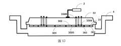
隨著反應的化學氣體的種類和比例發生了變化,圖12中緊鄰所述圓形氣體分配區域301的環形氣體分配區域302對應的區域的等離子體處理速率變為低於其他區域,則說明該區域內的反應氣體密度較小,可以通過縮小該區域對應的環形氣體分配區域302的面積來提高氣體密度。如圖13所示,如果選定的環形氣體分配區域302對應的區域的等離子體處理速率與其他區域相差的較大,則需要將所述選定的環形氣體分配區域302的面積縮小的多一些,所以選擇將最靠近圓心一側的環狀隔離層35中的所述柱狀隔板3508降下,通過旋轉所述螺桿3506帶動所述柱狀隔板3508下降,直至所述第一密封圈3503與所述安裝基板4壓緊貼合密封,利用所述螺母3507固定所述螺桿3506的當前位置,此時所述第二密封圈3504完全嵌入所述通孔3301內,實現所述柱狀隔板3508與所述氣體擋板31的底板33之間的密封,所述選定的環形氣體分配區域302的面積縮小了,從而提高了該環形氣體分配區域302內的反應氣體密度,隨之提高了與所述環形氣體分配區域302對應的區域的等離子體處理速率,使該選定的環形氣體分配區域302對應的區域的等離子體處理速率與其他區域達到一致,獲得均勻的等離子體處理速率。As the types and proportions of the reacted chemical gases change, the plasma processing rate of the region corresponding to the annular
通過設置可升降的柱狀隔板,實現對氣體擋板與安裝基板之間的圓形氣體分配區域和環形氣體分配區域的面積進行動態調節,可以適用於不同的化學氣體環境和不同的氣體比例,令不同的氣體分配區域面積對應不同的化學氣體環境和不同的氣體比例,大大提高了對等離子體處理速率進行調節的靈活性、靈敏度和準確性,提高了等離子體處理速率的均勻性,且操作簡單,提高了設備的適用度,縮短了製程調整試驗周期。By setting up and down column-shaped partitions, the area of the circular gas distribution area and the annular gas distribution area between the gas baffle and the installation substrate can be dynamically adjusted, which can be applied to different chemical gas environments and different gas ratios , so that different gas distribution area areas correspond to different chemical gas environments and different gas ratios, which greatly improves the flexibility, sensitivity and accuracy of adjusting the plasma processing rate, and improves the uniformity of the plasma processing rate. The operation is simple, the applicability of the equipment is improved, and the process adjustment test period is shortened.
儘管本發明的內容已經通過上述優選實施例作了詳細介紹,但應當認識到上述的描述不應被認為是對本發明的限制。在本案所屬技術領域中具有通常知識者閱讀了上述內容後,對於本發明的多種修改和替代都將是顯而易見的。因此,本發明的保護範圍應由所附的申請專利範圍來限定。While the content of the present invention has been described in detail by way of the above preferred embodiments, it should be appreciated that the above description should not be construed as limiting the present invention. Various modifications and substitutions to the present invention will be apparent to those of ordinary skill in the art to which the present application pertains after reading the above content. Therefore, the protection scope of the present invention should be defined by the appended claims.
1:真空反應腔2:外部供氣裝置3:氣體流量調節裝置301:圓形氣體分配區域302:環形氣體分配區域31:氣體擋板32:頂板33:底板3301:通孔3302:氣體通孔3303:環狀結構34:隔離組件35:環狀隔離層3501:環狀隔板3502:升降固定組件3503:第一密封圈3504:第二密封圈3505:波紋管3506:螺桿3507:螺母3508:柱狀隔板3509:扇環狀隔板36:連接組件4:安裝基板41:氣體通孔5:氣體噴淋頭51:氣體通孔6:等離子體7:基座8:靜電夾盤9:基片1: Vacuum reaction chamber2: External air supply device3: Gas flow adjustment device301: Circular gas distribution area302: annular gas distribution area31: Gas baffle32: Top plate33: Bottom plate3301: Through hole3302: Gas Through Holes3303: Ring structure34: Isolation Components35: Ring isolation layer3501: Ring Separator3502: Lifting and fixing components3503: The first sealing ring3504: Second seal3505: Bellows3506: Screw3507: Nut3508: Column Separator3509: Fan ring partition36: Connect Components4: Install the substrate41: Gas through hole5: Gas shower head51: Gas through hole6: Plasma7: Pedestal8: Electrostatic chuck9: Substrate
圖1是本發明提供的一種具有氣體流量調節裝置的等離子體處理裝置的結構示意圖。圖2是氣體流量調節裝置的結構示意圖。圖3是氣體流量調節裝置的俯視圖。圖4是本發明一種實施例中的隔離組件的結構示意圖。圖5是本發明一種實施例中的環狀隔離層的俯視圖。圖6是本發明一種實施例中的環狀隔離層的仰視圖。圖7和圖8是本發明一種實施例中動態調節氣體擋板中氣體分配區域的面積的示意圖。圖9是本發明另一種實施例中的隔離組件的結構示意圖。圖10是本發明另一種實施例中的環狀隔離層的俯視圖。圖11是本發明另一種實施例中的環狀隔離層的仰視圖。圖12和圖13是本發明另一種實施例中動態調節氣體擋板中氣體分配區域的面積的示意圖。FIG. 1 is a schematic structural diagram of a plasma processing device with a gas flow regulating device provided by the present invention.FIG. 2 is a schematic structural diagram of a gas flow regulating device.FIG. 3 is a plan view of the gas flow regulating device.FIG. 4 is a schematic structural diagram of an isolation assembly in an embodiment of the present invention.FIG. 5 is a top view of the annular isolation layer in one embodiment of the present invention.Figure 6 is a bottom view of the annular spacer layer in one embodiment of the present invention.7 and 8 are schematic diagrams of dynamically adjusting the area of the gas distribution area in the gas baffle according to an embodiment of the present invention.FIG. 9 is a schematic structural diagram of an isolation assembly in another embodiment of the present invention.FIG. 10 is a top view of the annular isolation layer in another embodiment of the present invention.Figure 11 is a bottom view of the annular spacer layer in another embodiment of the present invention.12 and 13 are schematic diagrams of dynamically adjusting the area of the gas distribution area in the gas baffle according to another embodiment of the present invention.
301:圓形氣體分配區域301: Circular gas distribution area
302:環形氣體分配區域302: annular gas distribution area
31:氣體擋板31: Gas baffle
32:頂板32: Top plate
33:底板33: Bottom plate
3301:通孔3301: Through hole
3302:氣體通孔3302: Gas Through Holes
3303:環狀結構3303: Ring structure
34:隔離組件34: Isolation Components
4:安裝基板4: Install the substrate
Claims (24)
Translated fromChineseApplications Claiming Priority (2)
| Application Number | Priority Date | Filing Date | Title |
|---|---|---|---|
| CN202010858525.4ACN114093739B (en) | 2020-08-24 | 2020-08-24 | Gas flow regulating device and regulating method and plasma processing device |
| CN202010858525.4 | 2020-08-24 |
Publications (2)
| Publication Number | Publication Date |
|---|---|
| TW202209403Atrue TW202209403A (en) | 2022-03-01 |
| TWI795807B TWI795807B (en) | 2023-03-11 |
Family
ID=80295569
Family Applications (1)
| Application Number | Title | Priority Date | Filing Date |
|---|---|---|---|
| TW110122197ATWI795807B (en) | 2020-08-24 | 2021-06-17 | Gas flow adjustment device and adjustment method, and plasma processing device |
Country Status (2)
| Country | Link |
|---|---|
| CN (1) | CN114093739B (en) |
| TW (1) | TWI795807B (en) |
Families Citing this family (2)
| Publication number | Priority date | Publication date | Assignee | Title |
|---|---|---|---|---|
| CN117877958B (en)* | 2024-03-12 | 2024-05-07 | 上海谙邦半导体设备有限公司 | Semiconductor processing equipment |
| CN120291061B (en)* | 2025-06-09 | 2025-08-26 | 蓝河科技(绍兴)有限公司 | Gas distribution equipment and semiconductor equipment |
Family Cites Families (16)
| Publication number | Priority date | Publication date | Assignee | Title |
|---|---|---|---|---|
| US6800173B2 (en)* | 2000-12-15 | 2004-10-05 | Novellus Systems, Inc. | Variable gas conductance control for a process chamber |
| US20060191637A1 (en)* | 2001-06-21 | 2006-08-31 | John Zajac | Etching Apparatus and Process with Thickness and Uniformity Control |
| JP5308664B2 (en)* | 2005-09-01 | 2013-10-09 | パナソニック株式会社 | Plasma processing equipment |
| US8440049B2 (en)* | 2006-05-03 | 2013-05-14 | Applied Materials, Inc. | Apparatus for etching high aspect ratio features |
| US20080302303A1 (en)* | 2007-06-07 | 2008-12-11 | Applied Materials, Inc. | Methods and apparatus for depositing a uniform silicon film with flow gradient designs |
| JP5444044B2 (en)* | 2010-03-02 | 2014-03-19 | 東京エレクトロン株式会社 | Plasma processing apparatus and shower head |
| JP5927619B2 (en)* | 2010-05-06 | 2016-06-01 | エヴァテック・アクチェンゲゼルシャフトEvatec Ag | Plasma reactor |
| JP5792563B2 (en)* | 2011-08-31 | 2015-10-14 | 東京エレクトロン株式会社 | Plasma etching method and plasma etching apparatus |
| US9896769B2 (en)* | 2012-07-20 | 2018-02-20 | Applied Materials, Inc. | Inductively coupled plasma source with multiple dielectric windows and window-supporting structure |
| US20140271097A1 (en)* | 2013-03-15 | 2014-09-18 | Applied Materials, Inc. | Processing systems and methods for halide scavenging |
| CN107435139A (en)* | 2016-05-26 | 2017-12-05 | 灿美工程股份有限公司 | Gas distributor and substrate board treatment |
| JP6851188B2 (en)* | 2016-11-28 | 2021-03-31 | 東京エレクトロン株式会社 | Plasma processing equipment and shower head |
| JP6960830B2 (en)* | 2017-11-17 | 2021-11-05 | 株式会社日立ハイテク | Vacuum processing equipment and operation method of vacuum processing equipment |
| CN109065432A (en)* | 2018-08-03 | 2018-12-21 | 德淮半导体有限公司 | A kind of dry etching equipment |
| CN109273339B (en)* | 2018-09-18 | 2021-03-19 | 惠科股份有限公司 | Reaction chamber, dry etching equipment and etching method |
| KR102623545B1 (en)* | 2018-12-17 | 2024-01-10 | 삼성전자주식회사 | Apparatus for manufacturing semiconductor device |
- 2020
- 2020-08-24CNCN202010858525.4Apatent/CN114093739B/enactiveActive
- 2021
- 2021-06-17TWTW110122197Apatent/TWI795807B/enactive
Also Published As
| Publication number | Publication date |
|---|---|
| TWI795807B (en) | 2023-03-11 |
| CN114093739B (en) | 2024-03-12 |
| CN114093739A (en) | 2022-02-25 |
Similar Documents
| Publication | Publication Date | Title |
|---|---|---|
| US11804366B2 (en) | Plasma processing apparatus | |
| TWI860154B (en) | Dynamic sheath control with edge ring lift | |
| KR102009595B1 (en) | Substrate support providing gap height and planarization adjustment in plasma processing chamber | |
| TWI651798B (en) | Mounting table and plasma processing device | |
| US8696862B2 (en) | Substrate mounting table, substrate processing apparatus and substrate temperature control method | |
| JP6660936B2 (en) | Symmetric chamber body design architecture to address variable processing volumes with improved flow uniformity / gas conductance | |
| TWI816876B (en) | Coaxial lift device with dynamic leveling | |
| TW202036652A (en) | Apparatus for processing substrate and lifting solution for substrate edge ring of the apparatus | |
| KR20170074755A (en) | Showerhead assembly | |
| TW202209403A (en) | Gas flow regulation device and regulation method and plasma processing device wherein the gas flow regulation device comprises a gas baffle and multiple liftable isolation assemblies arranged on the gas baffle | |
| CN102142357A (en) | Plasma processing apparatus | |
| TW201528883A (en) | Plasma processing apparatus | |
| JP2000294538A (en) | Vacuum processing equipment | |
| TWI853230B (en) | Chuck device and a semiconductor processing equipment | |
| KR20110057510A (en) | Dry etching equipment | |
| TW202125574A (en) | Lower electrode assembly, plasma processing device using the same and working method thereof characterized by achieving the effect of performing an adjustment on the temperature distribution of the electrostatic chuck | |
| TWI790462B (en) | Plasma treatment device and method including adjustable lifting thimble assembly | |
| CN112750676B (en) | Plasma processing device | |
| CN101440524B (en) | Plasma chemical reactor | |
| TW202029404A (en) | Radio Frequency Electrode Assembly for Plasma Processing Apparatus, And Plasma Processing Apparatus | |
| CN102623379A (en) | Electrostatic holding device and semiconductor processing apparatus | |
| KR102370516B1 (en) | Electrostatic chuck, placing table and plasma processing apparatus | |
| CN110323150B (en) | Temperature control device | |
| WO2025010254A1 (en) | Finger electrostatic chuck for high resistance substrate chucking | |
| TW202507897A (en) | Semiconductor process chambers and semiconductor process equipment |