TW202136753A - Reflective fourier ptychography imaging of large surfaces - Google Patents
Reflective fourier ptychography imaging of large surfacesDownload PDFInfo
- Publication number
- TW202136753A TW202136753ATW109142173ATW109142173ATW202136753ATW 202136753 ATW202136753 ATW 202136753ATW 109142173 ATW109142173 ATW 109142173ATW 109142173 ATW109142173 ATW 109142173ATW 202136753 ATW202136753 ATW 202136753A
- Authority
- TW
- Taiwan
- Prior art keywords
- rfpm
- imaging microscope
- component
- light sources
- light source
- Prior art date
Links
Images


Classifications
- G—PHYSICS
- G02—OPTICS
- G02B—OPTICAL ELEMENTS, SYSTEMS OR APPARATUS
- G02B21/00—Microscopes
- G02B21/06—Means for illuminating specimens
- G02B21/08—Condensers
- G02B21/14—Condensers affording illumination for phase-contrast observation
- G—PHYSICS
- G01—MEASURING; TESTING
- G01N—INVESTIGATING OR ANALYSING MATERIALS BY DETERMINING THEIR CHEMICAL OR PHYSICAL PROPERTIES
- G01N21/00—Investigating or analysing materials by the use of optical means, i.e. using sub-millimetre waves, infrared, visible or ultraviolet light
- G01N21/17—Systems in which incident light is modified in accordance with the properties of the material investigated
- G01N21/47—Scattering, i.e. diffuse reflection
- G01N21/4795—Scattering, i.e. diffuse reflection spatially resolved investigating of object in scattering medium
- G—PHYSICS
- G01—MEASURING; TESTING
- G01N—INVESTIGATING OR ANALYSING MATERIALS BY DETERMINING THEIR CHEMICAL OR PHYSICAL PROPERTIES
- G01N21/00—Investigating or analysing materials by the use of optical means, i.e. using sub-millimetre waves, infrared, visible or ultraviolet light
- G01N21/84—Systems specially adapted for particular applications
- G01N21/88—Investigating the presence of flaws or contamination
- G01N21/8806—Specially adapted optical and illumination features
- G—PHYSICS
- G01—MEASURING; TESTING
- G01N—INVESTIGATING OR ANALYSING MATERIALS BY DETERMINING THEIR CHEMICAL OR PHYSICAL PROPERTIES
- G01N21/00—Investigating or analysing materials by the use of optical means, i.e. using sub-millimetre waves, infrared, visible or ultraviolet light
- G01N21/84—Systems specially adapted for particular applications
- G01N21/88—Investigating the presence of flaws or contamination
- G01N21/8851—Scan or image signal processing specially adapted therefor, e.g. for scan signal adjustment, for detecting different kinds of defects, for compensating for structures, markings, edges
- G—PHYSICS
- G02—OPTICS
- G02B—OPTICAL ELEMENTS, SYSTEMS OR APPARATUS
- G02B21/00—Microscopes
- G02B21/0004—Microscopes specially adapted for specific applications
- G02B21/002—Scanning microscopes
- G02B21/0024—Confocal scanning microscopes (CSOMs) or confocal "macroscopes"; Accessories which are not restricted to use with CSOMs, e.g. sample holders
- G02B21/0032—Optical details of illumination, e.g. light-sources, pinholes, beam splitters, slits, fibers
- G—PHYSICS
- G02—OPTICS
- G02B—OPTICAL ELEMENTS, SYSTEMS OR APPARATUS
- G02B21/00—Microscopes
- G02B21/0004—Microscopes specially adapted for specific applications
- G02B21/002—Scanning microscopes
- G02B21/0024—Confocal scanning microscopes (CSOMs) or confocal "macroscopes"; Accessories which are not restricted to use with CSOMs, e.g. sample holders
- G02B21/0036—Scanning details, e.g. scanning stages
- G—PHYSICS
- G02—OPTICS
- G02B—OPTICAL ELEMENTS, SYSTEMS OR APPARATUS
- G02B21/00—Microscopes
- G02B21/06—Means for illuminating specimens
- G02B21/08—Condensers
- G02B21/082—Condensers for incident illumination only
- G—PHYSICS
- G02—OPTICS
- G02B—OPTICAL ELEMENTS, SYSTEMS OR APPARATUS
- G02B21/00—Microscopes
- G02B21/36—Microscopes arranged for photographic purposes or projection purposes or digital imaging or video purposes including associated control and data processing arrangements
- G02B21/365—Control or image processing arrangements for digital or video microscopes
- G02B21/367—Control or image processing arrangements for digital or video microscopes providing an output produced by processing a plurality of individual source images, e.g. image tiling, montage, composite images, depth sectioning, image comparison
- G—PHYSICS
- G01—MEASURING; TESTING
- G01N—INVESTIGATING OR ANALYSING MATERIALS BY DETERMINING THEIR CHEMICAL OR PHYSICAL PROPERTIES
- G01N21/00—Investigating or analysing materials by the use of optical means, i.e. using sub-millimetre waves, infrared, visible or ultraviolet light
- G01N21/84—Systems specially adapted for particular applications
- G01N21/88—Investigating the presence of flaws or contamination
- G01N21/8851—Scan or image signal processing specially adapted therefor, e.g. for scan signal adjustment, for detecting different kinds of defects, for compensating for structures, markings, edges
- G01N2021/8883—Scan or image signal processing specially adapted therefor, e.g. for scan signal adjustment, for detecting different kinds of defects, for compensating for structures, markings, edges involving the calculation of gauges, generating models
Landscapes
- Physics & Mathematics (AREA)
- General Physics & Mathematics (AREA)
- Analytical Chemistry (AREA)
- Chemical & Material Sciences (AREA)
- Optics & Photonics (AREA)
- Pathology (AREA)
- Biochemistry (AREA)
- General Health & Medical Sciences (AREA)
- Life Sciences & Earth Sciences (AREA)
- Health & Medical Sciences (AREA)
- Immunology (AREA)
- Engineering & Computer Science (AREA)
- Computer Vision & Pattern Recognition (AREA)
- Multimedia (AREA)
- Signal Processing (AREA)
- Investigating Materials By The Use Of Optical Means Adapted For Particular Applications (AREA)
- Microscoopes, Condenser (AREA)
- Investigating Or Analysing Materials By Optical Means (AREA)
Abstract
Description
Translated fromChinese所揭示之標的大體上係關於偵測表面和近表面上之缺陷(表面下的缺陷)的領域。更具體而言,所揭示之標的係關於使用反射型傅立葉疊層成像系統的自動缺陷偵測。[相關申請案的交互參照]The disclosed subject matter generally relates to the field of detecting defects on the surface and near the surface (defects under the surface). More specifically, the subject of the disclosure relates to automatic defect detection using a reflective Fourier stacked imaging system.[Cross-reference of related applications]
本申請案主張2019年12月2日提交的案名為「REFLECTIVE FOURIER PTYCHOGRAPHY IMAGING OF LARGE SURFACES」的美國專利申請案第62/942,636號的優先權,在此將其全文引入以供參照。This application claims the priority of US Patent Application No. 62/942,636 filed on December 2, 2019 titled "REFLECTIVE FOURIER PTYCHOGRAPHY IMAGING OF LARGE SURFACES", the full text of which is hereby incorporated by reference.
用於表面之同時相機檢測技術利用具有較大視域和低解析度的昂貴相機、或具有高放大率和高解析度但伴隨較小視域的系統。例如,當前的機器視覺技術無法以足夠的解析度適時地檢測整個部件的表面(例如,其面積可為大約0.25 m2)。Simultaneous camera inspection technology for surfaces utilizes expensive cameras with a large field of view and low resolution, or a system with high magnification and high resolution but accompanied by a small field of view. For example, the current machine vision technology cannot timely detect the surface of the entire part with sufficient resolution (for example, its area may be about 0.25 m2 ).
利用透射型技術的一種先前技術系統在使用具有較小數值孔徑之集光元件的同時實現高放大率技術,從而允許對較大圖像區域進行取樣。參照圖1,先前技術的透射型傅立葉疊層成像顯微鏡(TFPM)設備100的簡圖係顯示為具有可程式LED陣列110之形式的多工照明。TFPM設備100使用具有可程式LED陣列110作為光源的習知明場顯微鏡120。可程式LED陣列110促使照明101在樣品103之傅立葉平面109處形成周密的型樣。來自樣品103的光105穿過明場顯微鏡120的第一光學透鏡107及第二光學透鏡111。透射光113被成像裝置115所接收。成像裝置115可包含相機。從成像裝置115獲得的圖像資料係電耦合至計算裝置117。圖像資料係從成像裝置115傳輸至計算裝置117,以進行處理並最終顯示在監視器(未圖示)上。A prior art system using transmissive technology implements high magnification technology while using light collection elements with a smaller numerical aperture, thereby allowing a larger image area to be sampled. Referring to FIG. 1, a schematic diagram of a prior art transmission type Fourier stack imaging microscope (TFPM)
LED陣列110包含一可程式控制器(未圖示,但為熟習本技藝者可理解),其係配置以按預定的型樣及時間順序使設置在LED陣列110的面上的一或更多發光二極體發光(作為時間的函數)。因此,圖1的圖式顯示使用傅立葉疊層成像技術的先前技術系統,其促成使用具有較大視域(FOV)的低數值孔徑(NA)物鏡。即使使用低NA物鏡,傅立葉疊層成像設備因各種光源及所產生之光的型樣而仍能夠在整個圖像上獲得高解析度。除了所示之LED陣列110之外,傅立葉疊層成像顯微鏡設備的各種先前技術實例還使用可相對於樣品而傾斜並重新定位的照明源(例如,LED)。The
然而,即使TFPM設備100及類似的先前技術設備具有針對透射型顯微鏡的許多有用的應用,但TFPM設備100僅對允許光從其通過的物體(例如生物樣品)有用。因此,TFPM設備100不適用於反射式顯微鏡及成像技術。再者,TFPM設備100較不適用於掃描具有如上述之表面積的大樣品。However, even though the
此章節中所述之資訊係供以對熟習本技藝者提供以下所揭示標的之背景,而不應被視為所承認之先前技術。The information described in this chapter is provided to provide the background of the following disclosed subject matter for those who are familiar with the art, and should not be regarded as recognized prior art.
所揭示之標的之實施例描述一種反射型傅立葉疊層成像顯微鏡(RFPM)之操作方法,用以偵測部件之表面上的缺陷。該方法包含:將該部件裝載於該RFPM之固持夾具上;以及從多組分光源產生至少一個照明型樣,該多組分光源係配置以將輻射引導至該表面上。該多組分光源具有複數個別光源,該複數個別光源之各者係配置以個別地啟動。該至少一個照明型樣係選自包括時間性型樣及空間性型樣的多個型樣。該方法更包含:在感測器元件中收集從該表面重定向的輻射;藉由微分相位差(DPC)技術從該感測器元件所收集之輻射中獲得相位導數量測結果;決定從該表面至該感測器元件的成像軸之間的角度;以及判定該表面上之一或更多缺陷的至少一高度特徵。The disclosed subject embodiment describes an operating method of a reflective Fourier stacked imaging microscope (RFPM) to detect defects on the surface of a component. The method includes: loading the component on the holding fixture of the RFPM; and generating at least one illumination pattern from a multi-component light source configured to direct radiation onto the surface. The multi-component light source has a plurality of individual light sources, and each of the plurality of individual light sources is configured to be individually activated. The at least one lighting pattern is selected from a plurality of patterns including a temporal pattern and a spatial pattern. The method further includes: collecting radiation redirected from the surface in the sensor element; obtaining a phase derivative measurement result from the radiation collected by the sensor element by differential phase difference (DPC) technology; The angle from the surface to the imaging axis of the sensor element; and at least one height feature for determining one or more defects on the surface.
所揭示之標的之另一實施例描述一種反射型傅立葉疊層成像顯微鏡(RFPM)之操作方法,用以偵測部件之表面上的缺陷。該方法包含:將待檢測的一非生物部件裝載於一夾具上;以及選擇一程式以運行和控制該RFPM之一或更多態樣。該等態樣可選自包括以下者之態樣:多組分光源的空間性型樣、該多組分光源的時間性型樣、待偵測之缺陷尺寸的範圍、待檢測之部件的區域、一或更多受偵測缺陷的至少一個高度特徵、以及欲紀錄之該非生物部件的多個圖像。Another embodiment of the disclosed subject describes an operating method of a reflective Fourier stacked imaging microscope (RFPM) to detect defects on the surface of a component. The method includes: loading a non-biological component to be tested on a jig; and selecting a program to run and control one or more aspects of the RFPM. The patterns can be selected from the following patterns: the spatial pattern of the multi-component light source, the temporal pattern of the multi-component light source, the size range of the defect to be detected, and the area of the component to be inspected , At least one height feature of one or more detected defects, and multiple images of the non-biological component to be recorded.
所揭示之標的之另一實施例描述一種反射型傅立葉疊層成像顯微鏡(RFPM)之操作方法,用以偵測部件之表面上的缺陷。該方法包含從多組分光源產生至少一個照明型樣,該多組分光源係配置以將輻射引導至該表面上。該多組分光源具有多個個別光源,該多個個別光源之各者係配置以個別地啟動。該至少一個照明型樣係選自時間性型樣及空間性型樣。該方法更包含:利用明場成像及暗場成像以對該表面之圖像的傅立葉空間進行取樣;在一感測器中收集從該表面重定向的輻射;藉由微分相位差(DPC)技術從該感測器所收集之經重定向的輻射中獲得靠近缺陷之區域中的相位導數量測結果;決定從該表面至該感測器的成像軸之間的角度;以及判定該表面上之一或更多缺陷的至少一高度特徵。Another embodiment of the disclosed subject describes an operating method of a reflective Fourier stacked imaging microscope (RFPM) to detect defects on the surface of a component. The method includes generating at least one illumination pattern from a multi-component light source configured to direct radiation onto the surface. The multi-component light source has a plurality of individual light sources, and each of the plurality of individual light sources is configured to be individually activated. The at least one lighting pattern is selected from a temporal pattern and a spatial pattern. The method further includes: using bright-field imaging and dark-field imaging to sample the Fourier space of the image of the surface; collecting radiation redirected from the surface in a sensor; using differential phase difference (DPC) technology Obtain the phase derivative measurement result in the area close to the defect from the redirected radiation collected by the sensor; determine the angle from the surface to the imaging axis of the sensor; and determine the difference on the surface At least one height characteristic of one or more defects.
以下描述包括體現所揭示標的之各種態樣的說明性示例、裝置、和設備。在以下的敘述中,為了說明之目的,描述了大量的特定細節,以提供對發明標的之各種實施例的理解。然而,對於熟習本技藝者而言,顯然可在沒有該等特定細節之情況下實行所揭示之標的之各種實施例。再者,公知的結構、材料、和技術未被詳細顯示出,以免混淆各個所示出之實施例。The following description includes illustrative examples, devices, and equipment that embody various aspects of the disclosed subject matter. In the following description, for illustrative purposes, a large number of specific details are described to provide an understanding of various embodiments of the subject of the invention. However, for those who are familiar with the art, it is obvious that various embodiments of the disclosed subject matter can be implemented without the specific details. Furthermore, well-known structures, materials, and techniques have not been shown in detail, so as not to obscure the illustrated embodiments.
以下討論的各種例示實施例聚焦於反射型傅立葉疊層成像顯微鏡(RFPM)設備。在閱讀並理解了本文所提供的揭示內容之後,熟習本技藝者將輕易理解,各種技術、設計、和範例可全部以各種組合方式加以應用。作為對本主題的介紹,將在以下段落中簡要且概括地描述一些實施例,然後將參照圖式而進行更詳細的描述。The various exemplary embodiments discussed below focus on reflective Fourier stacked imaging microscope (RFPM) equipment. After reading and understanding the disclosure provided in this article, those who are familiar with the art will easily understand that various technologies, designs, and examples can all be applied in various combinations. As an introduction to the subject, some embodiments will be briefly and summarized in the following paragraphs, and then will be described in more detail with reference to the drawings.
當前製造商用於檢測部件的檢測系統和方法依賴於包括人工檢測及機器檢測的技術,人工檢測係用於測出部件中的大缺陷(例如,具有約500 µm以上的「直徑」),而機器檢測對部件表面的一小部分進行檢測以測出微小的缺陷(例如,約10 µm以上)。各個製造商(例如,半導體製程及計量工具的製造商)所使用之該等檢測系統和方法大體上僅檢測約0.0003%至約0.0007%的部件表面,並且使用此小樣本對整個部件的品質進行推斷和假設。此等對部件的較小檢測百分比使得受檢測表面代表部件的實際品質狀態之信賴度僅為約2%至約4%。當代的系統和方法僅檢測很小一部分的部件之原因係基於光學元件的物理特性,如以下簡要地描述。Current inspection systems and methods used by manufacturers to inspect parts rely on technologies including manual inspection and machine inspection. Manual inspection is used to detect large defects in parts (for example, having a "diameter" greater than about 500 µm). Inspection is performed on a small part of the surface of the part to detect tiny defects (for example, about 10 µm or more). The inspection systems and methods used by various manufacturers (for example, manufacturers of semiconductor processes and metrology tools) generally only inspect about 0.0003% to about 0.0007% of the part surface, and use this small sample to evaluate the quality of the entire part. Inferences and assumptions. These small detection percentages of the components make the tested surface representative of the actual quality status of the components only about 2% to about 4%. The reason why contemporary systems and methods only detect a small part of the components is based on the physical characteristics of the optical components, as briefly described below.
如熟習本技藝者所理解,基於顯微鏡之檢測系統通常使用顯微鏡物鏡來收集穿透通過物體的光或從物體反射的光。熟習本技藝者理解雷利(Rayleigh)解析度極限(LR) (顯微鏡可解析多小的特徵部)係基於以下方程式:

然而,隨著NA增加,景深(例如,圖像深度)及可視區域顯著減小。例如,根據以下公式,景深(DOF)按數值孔徑(NA)的平方減小:
例如,所揭示之標的的設備及方法可在不到約30分鐘的時間內以與先前技術之基於標準顯微術的系統相似的解析度檢測部件的整個表面,其與上述取樣約0.0003%至約0.0007%的情況相比,在效率方面提高了超過約13,000倍,從而顯著改善量測的信賴度,使得信賴度高達約95%至約99.9997%。For example, the disclosed subject equipment and method can detect the entire surface of the component with a resolution similar to the standard microscopy-based system of the prior art in less than about 30 minutes, which is about 0.0003% to about 0.0003% to the above sampling. Compared with the case of about 0.0007%, the efficiency is increased by more than about 13,000 times, thereby significantly improving the reliability of the measurement, making the reliability as high as about 95% to about 99.9997%.
所揭示之標的之各種實施例以反射方式運行,俾對例如硬質表面(例如,非生物的,如無機或非有機的物質)進行檢測。該等表面可包含例如各種金屬(例如,鋁或不銹鋼)、陶瓷(例如,氧化鋁、Al2O3)表面、經陶瓷塗佈的表面、元素和化合物半導體基板表面、各種類型的塑料、玻璃表面(本領域中已知的各種類型)、陽極氧化表面、及氧化表面,儘管許多其他類型的表面及材料亦可使用所揭示之標的之實施例來檢測。在一範例中,部件的直徑(或其他特徵面積尺寸)可為約559 mm(約22英吋,具有約0.25 m2的單一側的表面積),並且可對部件進行檢測以獲知具有約5 µm至約10 µm以上之特徵尺寸的缺陷。在其他實施例中,可對部件進行檢測以獲知在多達數平方公尺之面積上具有約5 µm至約10 µm以上之特徵尺寸的缺陷。Various embodiments of the disclosed subject matter operate in a reflective manner to detect, for example, hard surfaces (for example, non-biological, such as inorganic or non-organic substances). These surfaces can include, for example, various metals (e.g., aluminum or stainless steel), ceramic (e.g., alumina, Al2 O3 ) surfaces, ceramic-coated surfaces, elemental and compound semiconductor substrate surfaces, various types of plastics, glass Surfaces (various types known in the art), anodized surfaces, and oxidized surfaces, although many other types of surfaces and materials can also be tested using the disclosed subject embodiment. In an example, the diameter (or other feature area size) of the part may be about 559 mm (about 22 inches, witha single side surface area of about 0.25 m 2 ), and the part may be inspected to know that it has about 5 µm Defects with feature sizes above about 10 µm. In other embodiments, the component may be inspected to detect defects having a feature size of about 5 µm to about 10 µm or more in an area as large as a few square meters.
所揭示之標的之各種實施例亦可用以例如識別材料組成變化、晶體結構變化、或材料內的晶界。具有不同組成或不同晶體結構的材料具有不同的折射率以作為該材料的特性。折射率影響光從材料反射和折射通過材料的方式。因此,各種折射率會產生不同強度的光入射到感測器上,從而允許偵測例如組成或結構的邊界。此外,若材料(如陶瓷或金屬)的晶粒尺寸為微米級,則可利用所揭示之標的之各種實施例來偵測通常需要更高的放大倍數進行觀看的晶界及其他缺陷。再者,從多個角度的光獲取之在晶界處散射的光所產生的圖像除了可識別比習知光學元件可偵測或識別者的尺度更大的較大缺陷以外,還可識別晶界資訊。The various embodiments of the disclosed subject matter can also be used, for example, to identify material composition changes, crystal structure changes, or grain boundaries within the material. Materials with different compositions or different crystal structures have different refractive indexes as the characteristics of the material. The refractive index affects the way light reflects from and refracts through the material. Therefore, various refractive indexes will produce different intensities of light incident on the sensor, allowing detection of, for example, composition or structure boundaries. In addition, if the grain size of the material (such as ceramic or metal) is on the order of micrometers, various embodiments of the disclosed subject matter can be used to detect grain boundaries and other defects that usually require a higher magnification for viewing. Furthermore, the image generated by the light scattered at the grain boundary obtained from the light from multiple angles can not only identify larger defects than those that can be detected or identified by conventional optical elements, but also identify Grain boundary information.
所揭示之標的使用具有較大視域的相機而仍可獲得高解析度。所述之設備的實施例使用空間上產生和時間上產生的多個角度的入射光,然後將其以計算方式結合俾增加解析度,並且係在待檢測之部件的大表面積上進行此等操作。由於大量入射光束撞擊在受檢測之部件的表面上,因此亦可減少或消除典型單一的高強度光束所造成的假影。所揭示之設備可使用統計和機器學習以僅審視表面的一部分且同時具有對於整個表面之品質的高信賴度。再者,可利用各種類型的透鏡(例如,物鏡)及波長來修改所揭示之標的之各種實施例,以滿足其所需之特定應用。此外,可使本文所述之各種實施例自動化以掃描整個表面。例如,在一實施例中,為了增加受檢測的表面積,可對RFPM裝置進行光柵掃描或移動至待檢測之表面的不同部分。在另一實施例中,可相對於RFPM裝置而將表面平移。在其他實施例中,對RFPM裝置進行光柵掃描,並同時相對於RFPM裝置而將表面平移。再者,各種實施例可具有關於合格部件的預定標準,從而消除操作員對於偵測到一或更多缺陷進行解釋的需要。The disclosed subject uses a camera with a larger field of view and still obtains high resolution. The described embodiment of the device uses incident light at multiple angles generated in space and time, and then combined them in a computational manner to increase the resolution, and perform this operation on the large surface area of the component to be inspected . Since a large number of incident beams impinge on the surface of the component under inspection, the artifacts caused by a typical single high-intensity beam can also be reduced or eliminated. The disclosed device can use statistics and machine learning to view only a part of the surface and at the same time have high confidence in the quality of the entire surface. Furthermore, various types of lenses (for example, objective lenses) and wavelengths can be used to modify various embodiments of the disclosed subject matter to meet the specific application required. In addition, the various embodiments described herein can be automated to scan the entire surface. For example, in one embodiment, in order to increase the surface area to be inspected, the RFPM device may be raster-scanned or moved to different parts of the surface to be inspected. In another embodiment, the surface can be translated relative to the RFPM device. In other embodiments, the RFPM device is raster scanned and the surface is translated relative to the RFPM device at the same time. Furthermore, various embodiments may have predetermined criteria for qualified parts, thereby eliminating the need for the operator to explain the detection of one or more defects.
在一特定例示實施例中,所揭示之標的包含反射型傅立葉疊層成像顯微鏡(RFPM)設備。RFPM設備以反射方式運行,其利用多組分光源(例如,LED陣列或其他輻射源)、包含用於接收來自經受檢測之物體的鏡面反射光及散射光(從表面反射或重定向的光)之集光元件的透鏡、以及反射光感測器。在許多實施例中,反射光感測器可能從垂直方向(與表面呈正交)偏移一定度數。該系統在明場成像和暗場成像兩者中以不同的照明條件(例如,多組分光源的半圓照明)擷取多個圖像,以對表面圖像的傅立葉空間進行取樣。接著,將該等圖像以計算方式重建,並且將其疊加以提高解析度並減少像差。在進行重建之後,利用機器學習演算法審視圖像中的缺陷,並基於預定標準而判定部件品質。In a specific exemplary embodiment, the disclosed subject matter includes a reflective Fourier stack imaging microscope (RFPM) device. The RFPM device operates in a reflective manner, which utilizes a multi-component light source (for example, an LED array or other radiation source), including a specular reflection light and scattered light (light reflected or redirected from a surface) for receiving from an object subject to detection The lens of the light-collecting element and the reflective light sensor. In many embodiments, the reflective light sensor may be offset by a certain degree from the vertical direction (orthogonal to the surface). The system captures multiple images with different illumination conditions (for example, semicircular illumination of a multi-component light source) in both bright-field imaging and dark-field imaging, so as to sample the Fourier space of the surface image. Then, these images are reconstructed computationally and superimposed to improve resolution and reduce aberrations. After the reconstruction, machine learning algorithms are used to examine the defects in the image and determine the quality of the parts based on predetermined criteria.
現參照圖2,顯示根據所揭示之標的之各種實施例的反射型傅立葉疊層成像顯微鏡(RFPM)設備200之圖式的例示實施例。RFPM設備200係顯示為包含光源陣列210、集光元件230、及樣品表面203。光源陣列210包含許多的個別光源210A、210B、…、210N。在許多實施例中,個別光源210A、210B、…、210N可各自包含許多基本上單色的光源。光源陣列210可包含具有一或更多波長、一或更多偏振態、或其他特性的個別光源。在特定例示實施例中,個別光源210A、210B、…、210N包含特定波長的個別LED、或LED叢集,其中該等LED叢集係各自可針對相關色溫(CCT)或包含非可見色(例如紫外線或紅外線)的波長範圍而進行調諧的。在許多實施例中,個別光源可包含波長延伸深入紫外線範圍之其他類型的非可見光源。無論使用何種類型的光源,個別光源210A、210B、…、210N之各者皆為可程式的,並且能夠被個別地啟動(打開或關閉)。Referring now to FIG. 2, there is shown an illustrative embodiment of a diagram of a reflective Fourier stacked imaging microscope (RFPM)
集光元件230包含成像透鏡207及感測器元件209。雖然成像透鏡207係顯示為雙凸透鏡,但並非必然包含此等限制,因為,成像透鏡207可包含各種透鏡或透鏡群組之其中一或多者,如本領域中所公知。成像透鏡207係顯示為具有進入透鏡之光錐205的全角度。在特定例示實施例中,成像透鏡207可被其他光學元件(例如鏡件)替代或與其結合使用。在特定例示實施例中,集光元件230包含顯微鏡物鏡。感測器元件209可包含本領域中已知的各種類型之光感測元件,其將所接收之光能轉換為電信號輸出(例如,光偵測器)。在特定例示實施例中,感測器元件209包含CCD陣列。The
可將光源陣列210設置為相對於樣品表面203而成角度211。角度211可為固定或可變的,其取決於熟習本技藝者可理解的許多因素。在許多實施例中,角度211可從0°或接近0°至約2°、至約3°、至約5°或更大。再者,個別光源210A、210B、…、210N之各者可具有各種量的光束展開度201。光束展開度可為0°或接近0°(例如,對於雷射或LED源而言),或者對於其他類型的光源而言可為大於0°。The
可將集光元件230設置為相對於樣品表面203而成角度213。角度213可為固定或可變的,其取決於熟習本技藝者可理解的許多因素。在許多實施例中,角度213可從0°或接近0°至約2°、至約3°、至約5°或更大。在特定例示實施例中,角度213大約等於光源陣列210的角度211。RFPM設備200的集光元件230收集從樣品表面203朝向集光元件230反射或散射回來的反射。The
因此,由於來自例如相干光源的照明而致使擷取了一系列圖像之各者。然而,歸因於多個光源,使得存在多個入射角,其中的許多入射角係實質上同時可利用的。RFPM設備200可採用光之各種類型的時間性或空間性型樣化以收集一系列圖像。Therefore, each of a series of images is captured due to illumination from, for example, a coherent light source. However, due to the multiple light sources, there are multiple incident angles, many of which are substantially available at the same time. The
因此,許多成像模態係利用圖2之相同光學設置方式來實現,在許多實施例中沒有移動部件,僅僅藉由根據預定的時間性和空間性型樣而選擇欲啟動(打開和關閉)的光源陣列210中之個別光源210A、210B、…、210N(例如LED)中的適當光源而實現。因此,光源陣列210中的個別光源之各者、或個別光源中之多者的型樣對應於樣品表面203在單一角度或角度範圍處的照明。因此,可加以型樣化的照明角度範圍比穿過集光元件230的角度範圍更大許多,因此不受集光元件230之數值孔徑所限制。因此,較靠近光源陣列210之中心區域的個別光源對樣品表面203的照明產生明場圖像,而較靠近光源陣列210之外周(在樣品表面203的數值孔徑之外)的個別光源對樣品表面203的照明產生暗場圖像。明場圖像及暗場圖像為熟習本技藝者所熟知和理解。Therefore, many imaging modalities are realized by using the same optical setting method as shown in Fig. 2. In many embodiments, there are no moving parts, and only the ones to be activated (opened and closed) are selected according to the predetermined temporal and spatial patterns. The
利用例如在光源陣列210的任一半(例如,跨選定的對稱線)上的LED依序地擷取一對圖像,允許RFPM設備200藉由微分相位差(DPC)技術而獲得相位導數(phase-derivative)量測結果。利用DPC技術,可獲得使用來自光源陣列210之不同來源型樣而擷取之圖像的定量相位差。因此,定量相位係根據例如利用互補的不對稱照明型樣所擷取的兩個圖像而回復。兩個圖像之間的差異與樣品表面203沿不對稱軸的相位導數有關。因此,DPC技術為部分相干成像技術(僅有來自單個LED的照明包含相干光源)。歸因於可使用光源陣列210實施的各種型樣化技術,使得可在RFPM設備200中實質上即時且沿著許多不對稱軸而實施DPC測量,而無需使用任何可動部件。因此,可在RFPM設備的照射側(光源陣列210之側)或偵測(反射回或散射回的)側(集光元件230之側)無需任何機械變更之情況下實施DPC技術。因此,可發展出光源陣列210的各種照明策略以適應不同類型的樣本及成像需求。Using, for example, LEDs on either half of the light source array 210 (for example, across a selected line of symmetry) to sequentially capture a pair of images, allowing the
熟習本技藝者理解,在光學元件及光散射之一般技術中,可從以下操作中獲取高度資訊:擷取多個圖像的一或更多相位差並使用此資訊來獲取高度特徵(例如,缺陷的特徵高度尺寸)。在使用明場圖像的反射式顯微鏡中,可例如擷取兩個半月形照明型態(例如,左右或上下)。在離軸照明情況下,相位會根據對比度而實質上線性變化。然而,在單一圖像中,相位資訊及波幅資訊兩者係不可分離地在所得信號中進行卷積,因此無法從信號中個別地獲取相位。來自不同角度的多個圖像會具有相同的波幅對比度,但具有不同的相位對比度。因此,當擷取複數圖像之間的差異時,可孤立出相位對比度。Those familiar with the art understand that in the general technology of optical elements and light scattering, height information can be obtained from the following operations: capturing one or more phase differences of multiple images and using this information to obtain height characteristics (for example, The characteristic height dimension of the defect). In a reflection microscope using brightfield images, for example, two half-moon illumination patterns (for example, left and right or up and down) can be captured. In the case of off-axis illumination, the phase changes substantially linearly according to the contrast. However, in a single image, both the phase information and the amplitude information are inseparably convolved in the resultant signal, so the phase cannot be obtained individually from the signal. Multiple images from different angles will have the same amplitude contrast but different phase contrasts. Therefore, when capturing the difference between multiple images, the phase contrast can be isolated.
在反射方式下,可透過下列方程式將相位與高度或深度相關聯:

以上提供的說明通常對單次反射(非透射信號)有效,儘管可使用一組相似的數學(雖然更為複雜)從透射的信號中獲取相似的資訊。在固體表面上有透明塗層的情況下,可能會遇到各種類型的反射。然而,熟習本技藝者將會理解如何可將此等反射包括在以上提供的方程式中。The explanations provided above are generally valid for single reflections (non-transmitted signals), although a similar set of mathematics (albeit more complicated) can be used to obtain similar information from transmitted signals. In the case of a transparent coating on a solid surface, various types of reflections may be encountered. However, those skilled in the art will understand how these reflections can be included in the equations provided above.
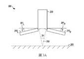
現參照圖3A,顯示根據所揭示之標的之各種實施例的RFPM設備300的圖式之另一例示實施例。RFPM設備300係顯示為包含左側光源陣列310L及右側光源陣列310R。光源陣列310L、310R之各者包含許多的個別光源(未圖示,但可與圖2的光源陣列210相同或相似)。左側光源陣列310L及右側光源陣列310R可分別成一或更多角度301L及301R。左側光源陣列310L及右側光源陣列310R之各者可成相對於對側之角度而有所不同的一或更多角度301L及301R。左側光源陣列310L及右側光源陣列310R之各者的相應角度301L及301R可為固定或可變的。此外,雖然並未明確圖示出,但RFPM設備300可包含分光鏡元件,俾使光源陣列310L、310R之其中至少一者可與集光元件230的射束路徑實質正交地設置。此等分光鏡設計在相關技術領域中係已知的。在其他實施例中,光源陣列可圍繞集光元件230,並且位於容置集光元件230的裝置中。再者,儘管圖3A暗指左側光源陣列310L及右側光源陣列310R為平面元件,但不應推定此等限制,如以下參照圖3B及3C所討論。Referring now to FIG. 3A, another exemplary embodiment of a diagram of an
圖3B及3C顯示可與圖3A之RFPM設備300一起使用的光源之配置的例示實施例。圖3B顯示具有多個個別光源330A、330B、…、330N之光源陣列330的配置320。因此,顯示出最下部(例如,光源陣列330的下側,其最靠近表面)。可基於待檢測之表面的給定尺寸及其他特性所需的多個個別光源而決定個別光源330A、330B、…、330N之相鄰的列之間的角度331。儘管角度331係顯示為相鄰的列之個別光源330A、330B、…、330N彼此相隔約45°,但不應推定對角度331的此等限制。3B and 3C show exemplary embodiments of the configuration of a light source that can be used with the
並且,個別光源330A、330B、…、330N可能並非依線性陣列的形式排列。個別光源可依各種空間週期性及非空間週期性(包括隨機)陣列的形式排列。例如,在特定例示實施例中,個別光源係依一系列同心圓的形式排列,其中每個相鄰的列具有與前一列或後一列相同數量的個別光源。在另一特定例示實施例中,個別光源係依一系列同心圓的形式排列,其中每個相鄰的列與前一列或後一列相比而具有數量更多或更少的個別光源。在又另一特定例示實施例中,個別光源係依阿基米德蝸線(Archimedes spiral)或其他幾何排列方式排列。此外,光源陣列330可包含局部平坦的表面(例如,從陣列的內周至外周)。在其他實施例中,光源陣列330可包含凹形或凸形表面、或者所列出或考量的幾何組合之任何者。Moreover, the
例如,圖3C顯示圖3A之RFPM設備300的配置之三維側視圖340。在此側視圖中,RFPM設備300係顯示為具有實質上為截頭圓錐形的形狀。角度341可從0°或接近0°至45°或更大。For example, FIG. 3C shows a three-
基於閱讀和理解所揭示之標的,熟習本技藝者將會明白,RFPM設備的各種實施例之各者可用於量測各種尺寸、在各種材料的表面上、及在大表面積上(例如,從幾分之一平方公尺到幾平方公尺或更多)的缺陷。在表面非常大的情況下,RFPM設備可被安裝在相關技術領域中已知的各種類型的平移台(例如,x-y平台或R-θ平台)上。在其他實施例中,可將樣品本身相對於RFPM設備而進行平移。在又其他實施例中,樣品與RFPM設備兩者皆可相對於彼此而進行平移。接著,可對所得的獲取圖像之各者進行處理,並透過例如軟體將其縫合在一起,以形成單一圖像。所偵測的缺陷之尺寸範圍可為約50 nm至約50 mm的受偵測缺陷之特徵尺寸。可偵測每單位面積之受偵測缺陷的總數(例如,超過預定尺寸如約5 µm或約10 µm)。此外,各種實施例可用以判定全部或部分的表面之整體粗糙程度(例如,RMS-粗糙度值(RRMS))。Based on reading and understanding the disclosed subject matter, those skilled in the art will understand that each of the various embodiments of the RFPM device can be used to measure various sizes, on the surface of various materials, and on large surface areas (for example, from several One-quarter square meter to several square meters or more) defects. In the case of a very large surface, the RFPM device can be installed on various types of translation stages known in the related art (for example, an xy platform or an R-θ platform). In other embodiments, the sample itself can be translated relative to the RFPM device. In still other embodiments, both the sample and the RFPM device can be translated relative to each other. Then, each of the obtained acquired images can be processed and stitched together through software, for example, to form a single image. The size of the detected defect can range from about 50 nm to about 50 mm of the characteristic size of the detected defect. The total number of detected defects per unit area (for example, exceeding a predetermined size such as about 5 µm or about 10 µm) can be detected. In addition, various embodiments can be used to determine the overall roughness (for example,RMS- roughness value (R RMS )) of all or part of the surface.
在其他實施例中,未明確圖示出但對於熟習本技藝者而言係可理解的,基於閱讀和理解所揭示之標的,所揭示之標的之各種實施例亦可於半導體製造的各個製程階段中使用。例如,所揭示之標的可於沉積製程腔室內或附近原位地使用,以在一或更多薄膜沉積於基板(例如矽晶圓)上時監視缺陷、薄膜厚度、及薄膜粗糙程度。接著,可將來自此等原位製程監視的結果實質即時地報告給終端使用者,或者將其採集並報告為一系列時間性圖像。In other embodiments, which are not explicitly shown but are understandable to those familiar with the art, based on reading and understanding the disclosed subject matter, various embodiments of the disclosed subject matter can also be used in each process stage of semiconductor manufacturing. Used in. For example, the disclosed subject matter can be used in situ in or near a deposition process chamber to monitor defects, film thickness, and film roughness as one or more films are deposited on a substrate (such as a silicon wafer). Then, the results from these in-situ process monitoring can be reported to the end user substantially in real time, or they can be collected and reported as a series of temporal images.
使用本文所揭示之各種實施例之其中一或多者,使用RFPM之各種實施例的一個實施例包含例如:(1) RFPM的操作員將待檢測之部件手動地加載至固定部件方向的夾具上;(2) 操作員選擇並起動程式以運行和控制上述RFPM之至少某些態樣,可利用人機界面或其他圖形化使用者界面運行該程式;(3) RFPM自動地擷取遍及整個部件表面或遍及預定部分(例如,在指定位置採樣的給定百分比之部件)的部件圖像(例如,可實質上同時偵測到1 µm及較大的500 µm之缺陷);(4) 一旦收集到所要求的資料,即利用相關技術領域中已知的計算方法來處理圖像,且利用例如機器學習來分析和量化缺陷;以及(5) 基於一組預定輸入(例如,缺陷數量等於或大於每單位面積的預定大小、所掃描之一部分或全部的部件上的粗糙程度、及本文所述之其他輸入及參數),程式電腦根據程式及所分析的缺陷而判定部件有通過或未通過檢測。Using one or more of the various embodiments disclosed herein, one of the various embodiments using RFPM includes, for example:(1) The operator of RFPM manually loads the parts to be inspected onto the fixture that fixes the direction of the part;(2) The operator selects and starts a program to run and control at least some aspects of the above-mentioned RFPM, and the program can be run using a man-machine interface or other graphical user interface;(3) RFPM automatically captures part images that cover the entire part surface or a predetermined part (for example, a given percentage of parts sampled at a specified position) (for example, it can detect 1 µm and larger parts at the same time). 500 µm defect);(4) Once the required information is collected, the image will be processed using calculation methods known in the relevant technical fields, and the defects will be analyzed and quantified using, for example, machine learning; and(5) Based on a set of predetermined inputs (for example, the number of defects is equal to or greater than the predetermined size per unit area, the roughness of part or all of the scanned parts, and other inputs and parameters described in this article), the program computer is based on The program and the analyzed defect determine whether the component has passed or failed inspection.
如上述之此等方法可於各種類型的裝置上運行,如以下更詳細地描述。該等裝置包括例如電腦或微處理器、專用處理器,如現場可程式邏輯閘陣列(FPGA)或特殊應用積體電路(ASIC),其係利用所揭示之上述標的之其中一或更多態樣以軟體、韌體、或硬體實施方式加以程式化。These methods as described above can be run on various types of devices, as described in more detail below. Such devices include, for example, computers or microprocessors, special-purpose processors, such as field programmable logic gate arrays (FPGA) or application-specific integrated circuits (ASIC), which utilize one or more of the disclosed above-mentioned subject aspects It is programmed by software, firmware, or hardware implementation.
在整個本說明書中,多個實例可實施被描述為單一實例的元件、操作、或結構。雖然將一或更多方法的個別操作例示和描述為單獨的操作,但可同時執行該等個別操作中之一或多者,且不需按所例示之順序執行該等操作。在例示性配置中表示為單獨元件的結構及功能可作為結合的結構或元件而實施。相似地,表示為單一元件的結構及功能可作為單獨元件而實施。該等及其他變化、修改、添加、及改良落於本文標的之範疇內。Throughout this specification, multiple examples may implement an element, operation, or structure described as a single example. Although the individual operations of one or more methods are illustrated and described as separate operations, one or more of the individual operations can be performed at the same time, and the operations do not need to be performed in the order illustrated. Structures and functions represented as separate elements in an exemplary configuration may be implemented as combined structures or elements. Similarly, the structure and function represented as a single element can be implemented as a single element. These and other changes, modifications, additions, and improvements fall within the scope of the subject of this article.
某些實施例在此處係描述為包含邏輯或若干元件、模組、或機構。模組可以構成軟體模組(例如,體現在機器可讀媒體上或傳輸信號中的代碼)或硬體模組。「硬體模組」為能夠執行某些操作的有形單元,並且可依某種物理方式配置或設置。在各種實施例中,可透過軟體將一或更多電腦系統(例如獨立電腦系統、客戶端電腦系統、或伺服器電腦系統)或電腦系統之一或更多硬體模組(例如處理器或處理器群組)配置為操作以執行本文所述之某些操作的硬體模組。Certain embodiments are described herein as including logic or several elements, modules, or mechanisms. The module may constitute a software module (for example, a code embodied on a machine-readable medium or in a transmission signal) or a hardware module. A "hardware module" is a tangible unit that can perform certain operations, and can be configured or set in a physical way. In various embodiments, one or more computer systems (such as stand-alone computer systems, client computer systems, or server computer systems) or one or more hardware modules (such as processors or The processor group) is configured as a hardware module that operates to perform certain operations described herein.
在某些實施例中,可機械式地、電子式地、或以其任何適當組合實施硬體模組。例如,硬體模組可包含專用電路或邏輯,其係永久配置以執行某些操作。例如,硬體模組可為專用處理器,例如現場可程式邏輯閘陣列(FPGA)或ASIC。In some embodiments, the hardware module can be implemented mechanically, electronically, or any suitable combination thereof. For example, a hardware module may include dedicated circuits or logic, which are permanently configured to perform certain operations. For example, the hardware module may be a dedicated processor, such as a field programmable logic gate array (FPGA) or ASIC.
硬體模組亦可包括可程式邏輯或電路,其係由軟體暫時配置以執行某些操作。例如,硬體模組可包括通用處理器或其他可程式處理器中包含的軟體。應理解,在成本和時間上的考量可決定機械式地、在專用且永久配置的電路中、或在暫時配置的電路(例如,由軟體配置)中實施硬體模組。The hardware module may also include programmable logic or circuits, which are temporarily configured by software to perform certain operations. For example, the hardware module may include software included in a general-purpose processor or other programmable processors. It should be understood that cost and time considerations may determine the implementation of the hardware module mechanically, in a dedicated and permanently configured circuit, or in a temporarily configured circuit (for example, configured by software).
因此,用語「硬體模組」應被理解為包括有形實體,為物理建構、永久配置(例如固線的)、或暫時配置(例如經編程)以某種方式操作或執行本文所述之某些操作的實體。如本文所用,「硬體實施模組」指涉硬體模組。考慮到硬體模組係暫時配置(例如經編程)的實施例,硬體模組之各者不需在任何時刻被配置或實體化。例如,在硬體模組包括由軟體配置為專用處理器的通用處理器之情況下,該通用處理器可在不同時間分別被配置為不同的專用處理器(例如,包含不同的硬體模組)。軟體可相應地配置處理器,以例如在一時間構成特定的硬體模組,並在不同時間構成不同的硬體模組。Therefore, the term "hardware module" should be understood to include tangible entities, which are physically constructed, permanently configured (for example, fixed-wire), or temporarily configured (for example, programmed) to operate in a certain manner or to perform certain operations described herein. These operating entities. As used herein, "hardware implementation module" refers to hardware modules. Considering the embodiment in which the hardware modules are temporarily configured (for example, programmed), each of the hardware modules does not need to be configured or materialized at any time. For example, when the hardware module includes a general-purpose processor configured as a dedicated processor by software, the general-purpose processor may be configured as a different dedicated processor at different times (for example, including different hardware modules). ). The software can configure the processor accordingly to, for example, form a specific hardware module at a time and form different hardware modules at different times.
硬體模組可提供資訊至其他硬體模組和從其他硬體模組接收資訊。因此,所述之硬體模組可被視為係通訊耦合的。在同時存在多個硬體模組的情況下,可透過在該等硬體模組中的兩者之間或更多者之間的信號傳輸(例如,透過適當的電路和匯流排)而達成通訊。在不同時間配置或實體化多個硬體模組的實施例中,可例如透過在多個硬體模組可存取的記憶體結構中儲存和擷取資訊而達成此等硬體模組之間的通訊。例如,一個硬體模組可執行一操作,並將該操作的輸出儲存在與其通訊耦合的記憶體裝置中。然後,另一硬體模組可在以後存取記憶體裝置以擷取和處理所儲存的輸出。硬體模組亦可啟動與輸入或輸出裝置的通訊,並且可在一資源(例如,資訊的集合)上進行操作。The hardware module can provide information to and receive information from other hardware modules. Therefore, the hardware module can be regarded as a communication coupling. In the case of multiple hardware modules at the same time, it can be achieved by signal transmission between two or more of these hardware modules (for example, through appropriate circuits and buses) communication. In an embodiment in which multiple hardware modules are configured or materialized at different times, for example, by storing and retrieving information in a memory structure accessible by multiple hardware modules, the integration of these hardware modules can be achieved. Inter-communication. For example, a hardware module can perform an operation and store the output of the operation in a memory device that is communicatively coupled with it. Then, another hardware module can later access the memory device to retrieve and process the stored output. The hardware module can also initiate communication with input or output devices, and can operate on a resource (for example, a collection of information).
本文所述之例示方法的各種操作可至少部分地由一或更多暫時配置(例如,透過軟體)或永久配置以執行相關操作的處理器加以執行。無論是暫時配置或永久配置,此等處理器都可構成處理器實施的模組,其運行以執行本文所述之一或更多操作或功能。如本文所用,「處理器實施的模組」指涉使用一或更多處理器實施的硬體模組。The various operations of the exemplified methods described herein can be performed at least in part by one or more processors that are temporarily configured (for example, through software) or permanently configured to perform related operations. Regardless of temporary configuration or permanent configuration, these processors may constitute a processor-implemented module, which operates to perform one or more operations or functions described herein. As used herein, "processor-implemented module" refers to a hardware module implemented using one or more processors.
相似地,本文所述之方法可至少部分地由處理器實施,處理器為硬體的範例。例如,方法的至少一些操作可由一或更多處理器或處理器實施的模組執行。再者,一或更多處理器亦可在「雲端運算」環境中或作為「軟體即服務」(SaaS)運行以支持相關操作的性能。例如,至少一些操作可由電腦群組(作為包含處理器之機器的實例)執行,其中該等操作可經由網絡(例如網際網路)和一或更多適當介面(例如,應用程式介面(API))而存取。Similarly, the methods described herein can be implemented at least in part by a processor, which is an example of hardware. For example, at least some operations of the method may be performed by one or more processors or processor-implemented modules. Furthermore, one or more processors can also run in a "cloud computing" environment or as a "software as a service" (SaaS) to support the performance of related operations. For example, at least some operations can be performed by a group of computers (as an example of a machine including a processor), where these operations can be performed via a network (such as the Internet) and one or more appropriate interfaces (such as an application programming interface (API)). ) And access.
某些操作的性能可分佈在一或更多處理器之間,不只駐留在單一機器內,而且係跨多個機器配置。在某些實施例中,可將一或更多處理器或處理器實施的模組可定位在單一地理位置(例如,在家庭環境,辦公室環境、或伺服器場內)。在其他實施例中,可使一或更多處理器或處理器實施的模組跨多個地理位置分佈。The performance of certain operations can be distributed among one or more processors, not only in a single machine, but also across multiple machine configurations. In some embodiments, one or more processors or processor-implemented modules can be located in a single geographic location (for example, in a home environment, an office environment, or a server farm). In other embodiments, one or more processors or processor-implemented modules may be distributed across multiple geographic locations.
如本文所用,「或」一詞能以包含或排他之意義來解釋。再者,熟習本技藝者於閱讀和理解所提供之揭示內容時將理解其他實施例。再者,於閱讀和理解本文所提供的揭示內容時,熟習本技藝者將輕易理解,本文所提供的化學品、技術、及範例之諸多組合都能以諸多組合應用。As used in this article, the word "or" can be interpreted in an inclusive or exclusive sense. Furthermore, those who are familiar with the art will understand other embodiments when reading and understanding the disclosed content provided. Furthermore, when reading and understanding the disclosure provided in this article, those familiar with the art will easily understand that the many combinations of chemicals, technologies, and examples provided in this article can be applied in many combinations.
儘管分開地討論諸多實施例,但該等分開的實施例不意圖視為獨立之技術或設計。如上文中所指示,諸多部分的每一者可為相互關聯的,且每一部分可分開地使用或與本文所討論之反射型傅立葉疊層成像系統之其他實施例結合使用,例如,雖然已描述方法、操作、及處理之各種實施例,但可將該等方法、操作、及處理分開使用或以各種組合方式使用。Although many embodiments are discussed separately, the separate embodiments are not intended to be regarded as independent technologies or designs. As indicated above, each of the many parts may be interrelated, and each part may be used separately or in combination with other embodiments of the reflective Fourier stack imaging system discussed herein, for example, although the method has been described , Operations, and processing in various embodiments, but these methods, operations, and processing can be used separately or in various combinations.
因此,對熟習本技藝者而言,在閱讀和理解本文所提供之揭示內容時將顯而易見的是,可做出許多修改和變動。除了本文所列舉之那些以外,於本揭示內容的範圍內之功能等效的方法和裝置對於熟習本技藝者而言由先前敘述將為顯而易見的。一些實施例之諸多部分和特徵可包括在其他實施例的部分和特徵中、或由其所替代。此等修改和變動意欲落入所附申請專利之範圍內。因此,本揭示內容僅藉由所附申請專利範圍的諸項、以及此等申請專利範圍所賦予之同等項的全部範圍來限制。亦應理解,本文所使用之術語僅出於敘述特定實施例之目的,而並非意圖進行限制。Therefore, for those who are familiar with the art, it will be obvious when reading and understanding the disclosure provided in this article that many modifications and changes can be made. In addition to those listed herein, functionally equivalent methods and devices within the scope of the present disclosure will be obvious from the foregoing description for those skilled in the art. Many parts and features of some embodiments may be included in or replaced by parts and features of other embodiments. These modifications and changes are intended to fall within the scope of the attached patent application. Therefore, the present disclosure is limited only by the items in the scope of the attached patent application and the full scope of the equivalent items given by the scope of the patent application. It should also be understood that the terms used herein are only for the purpose of describing specific embodiments and are not intended to be limiting.
提供本揭示內容之摘要以使讀者能夠快速確定所述技術揭示內容的本質。摘要之提交應理解為將不會用於解釋或限制所述之申請專利範圍。另外,在以上的實施方式內容中,可看出,出於簡化本揭示內容之目的,可在單一實施例中將諸多特徵組合在一起。本揭示內容之方法不應解釋為限制所述申請專利範圍。因此,在此將以下申請專利範圍併入實施方式內容中,使每一申請專利範圍獨立地作為單獨的實施例。以下帶有編號的範例為所揭示之標的之具體實施例A summary of this disclosure is provided to enable readers to quickly determine the nature of the technical disclosure. The submission of the abstract should be understood as it will not be used to explain or limit the scope of the patent application. In addition, in the above implementation content, it can be seen that for the purpose of simplifying the present disclosure, many features can be combined in a single embodiment. The method of this disclosure should not be construed as limiting the scope of the patent application. Therefore, the scope of the following patent applications is incorporated into the content of the embodiments, and each scope of patent applications is independently regarded as a separate embodiment.The following numbered examples are specific embodiments of the disclosed subject matter
範例1:所揭示之標的之實施例描述一種反射型傅立葉疊層成像顯微鏡(RFPM)之操作方法,用以偵測部件之表面上的缺陷。該方法包含:將該部件裝載於該RFPM之固持夾具上;從多組分光源產生至少一個照明型樣,該多組分光源係配置以將輻射引導至該表面上,該多組分光源具有複數個別光源,該複數個別光源之各者係配置以個別地啟動,該至少一個照明型樣係選自包括時間性型樣及空間性型樣的複數型樣;在感測器元件中收集從該表面重定向的輻射;藉由微分相位差(DPC)技術從該感測器元件所收集之輻射中獲得相位導數量測結果;決定一角度,其從垂直於該表面之線量起的成像軸至垂直於該表面之線與該感測器元件之間的角度;以及判定該表面上之一或更多缺陷的至少一高度特徵。Example 1: The disclosed subject embodiment describes an operating method of a reflective Fourier stacked imaging microscope (RFPM) to detect defects on the surface of a component. The method includes: loading the component on the holding fixture of the RFPM; generating at least one illumination pattern from a multi-component light source configured to direct radiation onto the surface, the multi-component light source having A plurality of individual light sources, each of the plurality of individual light sources is configured to be individually activated, and the at least one illumination pattern is selected from a plurality of patterns including a temporal pattern and a spatial pattern; collected from the sensor element The radiation redirected by the surface; the phase derivative measurement result is obtained from the radiation collected by the sensor element by differential phase difference (DPC) technology; determines an angle, which is the imaging axis measured from a line perpendicular to the surface The angle between the line perpendicular to the surface and the sensor element; and at least one height feature for determining one or more defects on the surface.
範例2:如範例1之方法,更包含在該表面的一區域上對至少一個所產生的光型樣進行光柵掃描。Example 2: The method as in Example 1, further comprising performing raster scanning on at least one of the generated light patterns on an area of the surface.
範例3:如範例1或範例2之方法,更包含藉由在該至少一個所產生的光型樣下移動該部件而在該表面的一區域上進行光柵掃描。Example 3: The method of Example 1 or Example 2, further comprising performing raster scanning on an area of the surface by moving the component under the at least one generated light pattern.
範例4:如前述範例之任一者之方法,更包含藉由以下步驟而在該表面的一區域上進行光柵掃描:在該表面的該區域上掃描該至少一個所產生的光型樣;以及在該至少一個所產生的光型樣下移動該部件。Example 4: The method of any one of the foregoing examples further includes performing raster scanning on an area of the surface by the following steps: scanning the at least one generated light pattern on the area of the surface; and The part is moved under the at least one generated light pattern.
範例5:如前述範例之任一者之方法,其中該區域係選擇為該表面上的至少約0.25平方公尺。Example 5: The method as in any of the preceding examples, wherein the area is selected to be at least about 0.25 square meters on the surface.
範例6:如前述範例之任一者之方法,更包含為該複數個別光源中之選定者決定至少一個波長。Example 6: The method of any one of the foregoing examples further includes determining at least one wavelength for the selected one of the plurality of individual light sources.
範例7:如前述範例之任一者之方法,其中該至少一個照明型樣係選擇為以多個入射角照射該表面。Example 7: The method as in any one of the preceding examples, wherein the at least one illumination pattern is selected to illuminate the surface at multiple incident angles.
範例8:如前述範例之任一者之方法,其中該時間性型樣及該空間性型樣係經預定的。Example 8: The method as in any of the preceding examples, wherein the temporal pattern and the spatial pattern are predetermined.
範例9:如前述範例之任一者之方法,其中選擇該時間性型樣之步驟包含:選擇該複數個別光源中之欲啟動的特定者;以及決定所選擇的複數個別光源中之特定者在時間上相對於所選擇的該複數個別光源中之其餘者而啟動。Example 9: The method as in any one of the foregoing examples, wherein the step of selecting the temporal pattern includes: selecting the specific one of the plurality of individual light sources to be activated; and determining that the specific one of the selected individual light sources is in It is activated in time relative to the rest of the selected plurality of individual light sources.
範例10:如前述範例之任一者之方法,其中選擇該空間性型樣之步驟包含:選擇在實質均勻的時段期間該複數個別光源中之欲啟動的特定者。Example 10: The method as in any one of the foregoing examples, wherein the step of selecting the spatial pattern includes: selecting a specific one of the plurality of individual light sources to be activated during a substantially uniform period of time.
範例11:如前述範例之任一者之方法,更包含決定至少一個所產生的光型樣之中點從垂直於該表面之線偏離的角度,其係偏離垂直於該表面之線一預定度數。Example 11: The method as in any of the foregoing examples, further comprising determining the angle at which the midpoint of at least one generated light pattern deviates from the line perpendicular to the surface, which is a predetermined number of degrees from the line perpendicular to the surface .
範例12:如前述範例之任一者之方法,更包含以計算方式結合從該表面重定向的經收集之輻射之其中至少一者,俾與給定的數值孔徑及該複數個別光源之光波長的雷利解析度極限(Rayleigh limit-of-resolution)相比而提高受偵測缺陷的解析度。Example 12: The method as in any one of the preceding examples, further comprising calculating at least one of the collected radiation redirected from the surface to be combined with a given numerical aperture and the light wavelength of the plurality of individual light sources Compared with the Rayleigh limit-of-resolution (Rayleigh limit-of-resolution), the resolution of detected defects is improved.
範例13:如前述範例之任一者之方法,更包含選擇集光元件以根據預定的數值孔徑將經收集之輻射聚焦至該感測器元件上。Example 13: The method as in any of the foregoing examples, further comprising selecting a light collecting element to focus the collected radiation on the sensor element according to a predetermined numerical aperture.
範例14:如前述範例之任一者之方法,其中該多組分光源包含一LED陣列。Example 14: The method as in any of the preceding examples, wherein the multi-component light source includes an LED array.
範例15:如前述範例之任一者之方法,其中產生該至少一個照明型樣之步驟包含選擇該複數個別光源中的複數者以包含LED陣列中的一組LED。Example 15: The method as in any of the preceding examples, wherein the step of generating the at least one illumination pattern includes selecting a plurality of the plurality of individual light sources to include a group of LEDs in the LED array.
範例16:如前述範例之任一者之方法,其中該多個個別光源之各者包含一LED。Example 16: The method as in any of the preceding examples, wherein each of the plurality of individual light sources includes an LED.
範例17:所揭示之標的之實施例描述一種反射型傅立葉疊層成像顯微鏡(RFPM)之操作方法。該方法包含:將待檢測的一非生物部件裝載於一夾具上;以及選擇一程式以運行和控制該RFPM之一或更多態樣,該等態樣可選自包括以下者之態樣:多組分光源的空間性型樣、該多組分光源的時間性型樣、待偵測之缺陷尺寸的範圍、待檢測之部件的區域、一或更多受偵測缺陷的至少一個高度特徵、以及欲紀錄之該非生物部件的多個圖像。Example 17: The disclosed subject-matter embodiment describes an operating method of a reflective Fourier stacked imaging microscope (RFPM). The method includes: loading a non-biological component to be tested on a jig; and selecting a program to run and control one or more aspects of the RFPM, and the aspects may be selected from the following aspects: The spatial pattern of the multi-component light source, the temporal pattern of the multi-component light source, the size range of the defect to be detected, the area of the component to be inspected, and at least one height feature of one or more detected defects , And multiple images of the non-biological part to be recorded.
範例18:如範例17之方法,更包含基於所記錄的該等圖像而判定該部件的該區域之至少一部分的粗糙程度。Example 18: The method of Example 17, further comprising determining the roughness of at least a part of the area of the part based on the recorded images.
範例19:如範例17或範例18之方法,更包含選擇待偵測之缺陷的尺寸範圍。Example 19: The method of Example 17 or Example 18 further includes selecting the size range of the defect to be detected.
範例20:如範例17至範例19之任一者之方法,更包含選擇該多組分光源將輻射引導至該部件的角度範圍。Example 20: The method of any one of Examples 17 to 19, further comprising selecting the multi-component light source to direct radiation to the angular range of the component.
範例21:如範例17至範例20之任一者之方法,其中該非生物部件包含選自包括以下者之材料的其中至少一種材料:金屬表面、陶瓷表面、經陶瓷塗佈的表面、元素半導體基板表面、化合物半導體基板表面、玻璃表面、陽極氧化表面、塑料、及氧化表面。Example 21: The method of any one of Examples 17 to 20, wherein the non-biological component includes at least one material selected from the group consisting of: a metal surface, a ceramic surface, a ceramic-coated surface, and an elemental semiconductor substrate Surface, compound semiconductor substrate surface, glass surface, anodized surface, plastic, and oxidized surface.
範例22:如範例17至範例21之任一者之方法,其中待偵測之缺陷的尺寸範圍包含在約50 nm至約50 mm之範圍內的受偵測缺陷之特徵尺寸。Example 22: The method as in any one of Examples 17 to 21, wherein the size range of the defect to be detected includes the characteristic size of the defect to be detected in the range of about 50 nm to about 50 mm.
範例23:所揭示之標的之實施例描述一種反射型傅立葉疊層成像顯微鏡(RFPM)之操作方法,用以偵測部件之表面上的缺陷。該方法包含:從多組分光源產生至少一個照明型樣,該多組分光源係配置以將輻射引導至該表面上,該多組分光源具有複數個別光源,該複數個別光源之各者係配置以個別地啟動,該至少一個照明型樣係選自時間性型樣及空間性型樣;利用明場成像及暗場成像以對該表面之圖像的傅立葉空間進行取樣;在一感測器中收集從該表面重定向的輻射;藉由微分相位差(DPC)技術從該感測器所收集之經重定向的輻射中獲得靠近缺陷之區域中的相位導數量測結果;決定一角度,其從垂直於該表面之線量起的成像軸至垂直於該表面之線與該感測器之間的角度;以及判定該表面上之一或更多缺陷的至少一高度特徵。Example 23: The disclosed subject embodiment describes an operating method of a reflective Fourier stacked imaging microscope (RFPM) to detect defects on the surface of a component. The method includes generating at least one illumination pattern from a multi-component light source configured to direct radiation onto the surface, the multi-component light source having a plurality of individual light sources, and each of the plurality of individual light sources is Configured to be activated individually, the at least one illumination pattern is selected from a temporal pattern and a spatial pattern; bright-field imaging and dark-field imaging are used to sample the Fourier space of the image of the surface; a sensing The radiation redirected from the surface is collected in the sensor; the differential phase difference (DPC) technique is used to obtain the phase derivative measurement result in the area near the defect from the redirected radiation collected by the sensor; determine an angle , The angle between the imaging axis measured from the line perpendicular to the surface to the line perpendicular to the surface and the sensor; and at least one height feature for determining one or more defects on the surface.
範例24:如範例23之方法,其中受偵測之缺陷的特徵尺寸為在多達數平方公尺之面積上之大約5 µm以上的尺寸。Example 24: As in the method of Example 23, the feature size of the defect to be detected is about 5 µm or more in an area up to a few square meters.
範例25:如範例23或範例24之方法,其中該部件為一非生物部件。Example 25: The method of Example 23 or Example 24, wherein the component is a non-biological component.
範例26:如範例25之方法,其中該非生物部件包含選自包括以下者之材料的其中至少一種材料:金屬表面、陶瓷表面、經陶瓷塗佈的表面、元素半導體基板表面、化合物半導體基板表面、玻璃表面、陽極氧化表面、塑料、及氧化表面。Example 26: The method of Example 25, wherein the non-biological component comprises at least one material selected from the group consisting of: metal surface, ceramic surface, ceramic-coated surface, elemental semiconductor substrate surface, compound semiconductor substrate surface, Glass surface, anodized surface, plastic, and oxidized surface.
範例27:如範例23至範例26之任一者之方法,其中該空間性型樣係選擇為在一選定的空間性型樣之時段期間實質上同時以多個入射角照射表面。Example 27: The method of any one of Examples 23 to 26, wherein the spatial pattern is selected to substantially simultaneously illuminate the surface at multiple incident angles during a period of a selected spatial pattern.
範例28:如範例23至範例27之任一者之方法,其中選擇該時間性型樣之步驟包含:選擇該複數個別光源中之欲啟動的特定者;以及決定所選擇的該複數個別光源中之特定者在時間上相對於所選擇的該複數個別光源中之其餘者而啟動。Example 28: The method of any one of Examples 23 to 27, wherein the step of selecting the temporal pattern includes: selecting the specific one of the plurality of individual light sources to be activated; and determining the selected one of the plurality of individual light sources The specific one is activated in time relative to the rest of the selected plurality of individual light sources.
範例29:如範例23至範例28之任一者之方法,其中選擇該空間性型樣之步驟包含:選擇在實質均勻的時段期間該複數個別光源中之欲啟動的特定者。Example 29: The method of any one of Examples 23 to 28, wherein the step of selecting the spatial pattern includes: selecting a specific one of the plurality of individual light sources to be activated during a substantially uniform time period.
100:透射型傅立葉疊層成像顯微鏡(TFPM)設備101:照明103:樣品105:光107:第一光學透鏡109:傅立葉平面110:LED陣列111:第二光學透鏡113:透射光115:成像裝置117:計算裝置120:明場顯微鏡200:反射型傅立葉疊層成像顯微鏡(RFPM)設備201:光束展開度203:樣品表面205:光錐207:成像透鏡209:感測器元件210:光源陣列210A:個別光源210B:個別光源210N:個別光源211:角度213:角度230:集光元件300:RFPM設備301L:角度301R:角度310L:左側光源陣列310R:右側光源陣列320:配置330:光源陣列330A:個別光源330B:個別光源330N:個別光源331:角度341:角度100: Transmission type Fourier stacked imaging microscope (TFPM) equipment101: lighting103: sample105: light107: The first optical lens109: Fourier plane110: LED array111: second optical lens113: transmitted light115: imaging device117: Computing Device120: Brightfield microscope200: Reflective Fourier stacked imaging microscope (RFPM) equipment201: Beam expansion203: sample surface205: Light Cone207: imaging lens209: sensor element210:
圖1顯示具有可程式LED陣列之形式的多工照明之先前技術的透射型傅立葉疊層成像顯微鏡設備的簡圖;Figure 1 shows a schematic diagram of a prior art transmissive Fourier stacked imaging microscope device with multiplexed illumination in the form of a programmable LED array;
圖2顯示根據所揭示之標的之各種實施例的反射型傅立葉疊層成像顯微鏡(RFPM)設備之圖式的例示實施例;FIG. 2 shows an exemplary embodiment of a schematic diagram of a reflective Fourier stacked imaging microscope (RFPM) apparatus according to various embodiments of the disclosed subject matter;
圖3A顯示根據所揭示之標的之各種實施例的RFPM設備的圖式之另一例示實施例;以及FIG. 3A shows another exemplary embodiment of a diagram of an RFPM device according to various embodiments of the disclosed subject matter; and
圖3B及3C顯示可與圖3A之RFPM設備一起使用的光源之配置的例示實施例。3B and 3C show exemplary embodiments of the configuration of a light source that can be used with the RFPM device of FIG. 3A.
200:反射型傅立葉疊層成像顯微鏡(RFPM)設備200: Reflective Fourier stacked imaging microscope (RFPM) equipment
201:光束展開度201: Beam expansion
203:樣品表面203: sample surface
205:光錐205: Light Cone
207:成像透鏡207: imaging lens
209:感測器元件209: sensor element
210:光源陣列210: light source array
210A:個別光源210A: Individual light source
210B:個別光源210B: Individual light source
210N:個別光源210N: Individual light source
211:角度211: Angle
213:角度213: Angle
230:集光元件230: light collecting element
Claims (29)
Translated fromChineseApplications Claiming Priority (2)
| Application Number | Priority Date | Filing Date | Title |
|---|---|---|---|
| US201962942636P | 2019-12-02 | 2019-12-02 | |
| US62/942,636 | 2019-12-02 |
Publications (1)
| Publication Number | Publication Date |
|---|---|
| TW202136753Atrue TW202136753A (en) | 2021-10-01 |
Family
ID=76222154
Family Applications (1)
| Application Number | Title | Priority Date | Filing Date |
|---|---|---|---|
| TW109142173ATW202136753A (en) | 2019-12-02 | 2020-12-01 | Reflective fourier ptychography imaging of large surfaces |
Country Status (6)
| Country | Link |
|---|---|
| US (1) | US20220413276A1 (en) |
| JP (2) | JP7678810B2 (en) |
| KR (1) | KR20220104821A (en) |
| CN (1) | CN115053122A (en) |
| TW (1) | TW202136753A (en) |
| WO (1) | WO2021113131A1 (en) |
Families Citing this family (5)
| Publication number | Priority date | Publication date | Assignee | Title |
|---|---|---|---|---|
| US11689821B2 (en)* | 2020-08-07 | 2023-06-27 | The Government Of The United States Of America, As Represented By The Secretary Of The Navy | Incoherent Fourier ptychographic super-resolution imaging system with priors |
| FR3125893A1 (en)* | 2021-07-29 | 2023-02-03 | Institut Mines Telecom | Lighting system, in particular for use in microscopy |
| KR20240108945A (en) | 2023-01-03 | 2024-07-10 | 삼성전자주식회사 | Substrate inspection apparatus and substrate inspection method |
| WO2024206952A1 (en)* | 2023-03-30 | 2024-10-03 | California Institute Of Technology | Angular ptychographic imaging with closed-form reconstruction |
| CN120254888B (en)* | 2025-05-30 | 2025-09-09 | 长春理工大学 | Underwater oil spill imaging detection method and equipment based on polarization correlation algorithm |
Family Cites Families (12)
| Publication number | Priority date | Publication date | Assignee | Title |
|---|---|---|---|---|
| CA2889495A1 (en)* | 2012-10-30 | 2014-05-08 | California Institute Of Technology | Fourier ptychographic imaging systems, devices, and methods |
| EP3011389A1 (en)* | 2013-06-17 | 2016-04-27 | Paul Scherrer Institut | Scanning coherent diffractive imaging method and system for actinic mask inspection for euv lithography |
| CN105765690B (en)* | 2013-08-22 | 2019-01-18 | 加州理工学院 | Variable Illumination Fourier Overlay Correlation Imaging Apparatus, System, and Method |
| DE102014213198B4 (en)* | 2014-07-08 | 2020-08-06 | Carl Zeiss Ag | Process for the localization of defects on substrates |
| WO2016090331A1 (en)* | 2014-12-04 | 2016-06-09 | California Institute Of Technology | Multiplexed fourier ptychography imaging systems and methods |
| CN107111118B (en)* | 2014-12-22 | 2019-12-10 | 加州理工学院 | EPI illumination Fourier ptychographic imaging for thick samples |
| AU2014280894A1 (en)* | 2014-12-23 | 2016-07-07 | Canon Kabushiki Kaisha | Illumination systems and devices for Fourier Ptychographic imaging |
| WO2016187591A1 (en)* | 2015-05-21 | 2016-11-24 | California Institute Of Technology | Laser-based fourier ptychographic imaging systems and methods |
| NL2017943A (en)* | 2015-12-23 | 2017-06-28 | Asml Netherlands Bv | Metrology methods, metrology apparatus and device manufacturing method |
| US10739275B2 (en)* | 2016-09-15 | 2020-08-11 | Kla-Tencor Corporation | Simultaneous multi-directional laser wafer inspection |
| CN106707486B (en)* | 2017-01-24 | 2019-07-26 | 清华大学 | FPM-based wide-field microscopy imaging method and system |
| KR20190088277A (en)* | 2018-01-18 | 2019-07-26 | 서울대학교산학협력단 | Microscopy system with single shot Fourier ptychography |
- 2020
- 2020-11-24USUS17/781,643patent/US20220413276A1/enactivePending
- 2020-11-24CNCN202080083517.5Apatent/CN115053122A/enactivePending
- 2020-11-24KRKR1020227022550Apatent/KR20220104821A/enactivePending
- 2020-11-24JPJP2022532572Apatent/JP7678810B2/enactiveActive
- 2020-11-24WOPCT/US2020/062108patent/WO2021113131A1/ennot_activeCeased
- 2020-12-01TWTW109142173Apatent/TW202136753A/enunknown
- 2025
- 2025-05-02JPJP2025076559Apatent/JP2025111782A/enactivePending
Also Published As
| Publication number | Publication date |
|---|---|
| JP7678810B2 (en) | 2025-05-16 |
| JP2023504151A (en) | 2023-02-01 |
| KR20220104821A (en) | 2022-07-26 |
| WO2021113131A1 (en) | 2021-06-10 |
| US20220413276A1 (en) | 2022-12-29 |
| CN115053122A (en) | 2022-09-13 |
| JP2025111782A (en) | 2025-07-30 |
Similar Documents
| Publication | Publication Date | Title |
|---|---|---|
| TW202136753A (en) | Reflective fourier ptychography imaging of large surfaces | |
| TWI724144B (en) | Methods and apparatus for polarized wafer inspection | |
| US8045145B1 (en) | Systems and methods for acquiring information about a defect on a specimen | |
| CN104950429B (en) | Including for providing repeatedly the 3D microscope of the pluggable component of imaging and measurement capability | |
| US20140268105A1 (en) | Optical defect inspection system | |
| US8885037B2 (en) | Defect inspection method and apparatus therefor | |
| CN106463431B (en) | Wafer edge detection method and inspection system | |
| US20100004875A1 (en) | Defect Inspection Method and Apparatus | |
| US6731383B2 (en) | Confocal 3D inspection system and process | |
| JP5472096B2 (en) | Imaging optical inspection apparatus and method for inspecting planar reflective surface of sample | |
| TW201506383A (en) | Apparatus and methods for finding a best aperture and mode to enhance defect detection | |
| WO2021197207A1 (en) | Apparatus for surface profile measurement | |
| JP2018516451A (en) | System and method for increasing inspection sensitivity of inspection tool | |
| US20020145734A1 (en) | Confocal 3D inspection system and process | |
| KR20200121907A (en) | Combining simulation and optical microscopy to determine inspection mode | |
| KR101652355B1 (en) | optical apparatus for examining pattern image of semiconductor wafer | |
| US11536648B2 (en) | Optical inspection device and method | |
| JP2017518485A (en) | Stereoscopic substrate scanning machine | |
| JP2024084208A (en) | Inspection device and inspection method | |
| Zhao et al. | Surface characterization using combined analysis of original and scatter image | |
| Ren et al. | Measurement of surface bidirectional reflectance distribution based on parabolic mirror |