TW202135983A - Polishing head system and polishing apparatus - Google Patents
Polishing head system and polishing apparatusDownload PDFInfo
- Publication number
- TW202135983A TW202135983ATW110109986ATW110109986ATW202135983ATW 202135983 ATW202135983 ATW 202135983ATW 110109986 ATW110109986 ATW 110109986ATW 110109986 ATW110109986 ATW 110109986ATW 202135983 ATW202135983 ATW 202135983A
- Authority
- TW
- Taiwan
- Prior art keywords
- polishing
- workpiece
- polishing head
- film thickness
- piezoelectric elements
- Prior art date
Links
Images


Classifications
- B—PERFORMING OPERATIONS; TRANSPORTING
- B24—GRINDING; POLISHING
- B24B—MACHINES, DEVICES, OR PROCESSES FOR GRINDING OR POLISHING; DRESSING OR CONDITIONING OF ABRADING SURFACES; FEEDING OF GRINDING, POLISHING, OR LAPPING AGENTS
- B24B37/00—Lapping machines or devices; Accessories
- B24B37/04—Lapping machines or devices; Accessories designed for working plane surfaces
- B24B37/07—Lapping machines or devices; Accessories designed for working plane surfaces characterised by the movement of the work or lapping tool
- B24B37/10—Lapping machines or devices; Accessories designed for working plane surfaces characterised by the movement of the work or lapping tool for single side lapping
- B24B37/105—Lapping machines or devices; Accessories designed for working plane surfaces characterised by the movement of the work or lapping tool for single side lapping the workpieces or work carriers being actively moved by a drive, e.g. in a combined rotary and translatory movement
- B—PERFORMING OPERATIONS; TRANSPORTING
- B24—GRINDING; POLISHING
- B24B—MACHINES, DEVICES, OR PROCESSES FOR GRINDING OR POLISHING; DRESSING OR CONDITIONING OF ABRADING SURFACES; FEEDING OF GRINDING, POLISHING, OR LAPPING AGENTS
- B24B37/00—Lapping machines or devices; Accessories
- B24B37/27—Work carriers
- B24B37/30—Work carriers for single side lapping of plane surfaces
- B24B37/32—Retaining rings
- B—PERFORMING OPERATIONS; TRANSPORTING
- B24—GRINDING; POLISHING
- B24B—MACHINES, DEVICES, OR PROCESSES FOR GRINDING OR POLISHING; DRESSING OR CONDITIONING OF ABRADING SURFACES; FEEDING OF GRINDING, POLISHING, OR LAPPING AGENTS
- B24B37/00—Lapping machines or devices; Accessories
- B24B37/005—Control means for lapping machines or devices
- B24B37/013—Devices or means for detecting lapping completion
- B—PERFORMING OPERATIONS; TRANSPORTING
- B24—GRINDING; POLISHING
- B24B—MACHINES, DEVICES, OR PROCESSES FOR GRINDING OR POLISHING; DRESSING OR CONDITIONING OF ABRADING SURFACES; FEEDING OF GRINDING, POLISHING, OR LAPPING AGENTS
- B24B37/00—Lapping machines or devices; Accessories
- B24B37/11—Lapping tools
- B24B37/20—Lapping pads for working plane surfaces
- B—PERFORMING OPERATIONS; TRANSPORTING
- B24—GRINDING; POLISHING
- B24B—MACHINES, DEVICES, OR PROCESSES FOR GRINDING OR POLISHING; DRESSING OR CONDITIONING OF ABRADING SURFACES; FEEDING OF GRINDING, POLISHING, OR LAPPING AGENTS
- B24B37/00—Lapping machines or devices; Accessories
- B24B37/34—Accessories
- B—PERFORMING OPERATIONS; TRANSPORTING
- B24—GRINDING; POLISHING
- B24B—MACHINES, DEVICES, OR PROCESSES FOR GRINDING OR POLISHING; DRESSING OR CONDITIONING OF ABRADING SURFACES; FEEDING OF GRINDING, POLISHING, OR LAPPING AGENTS
- B24B49/00—Measuring or gauging equipment for controlling the feed movement of the grinding tool or work; Arrangements of indicating or measuring equipment, e.g. for indicating the start of the grinding operation
- B—PERFORMING OPERATIONS; TRANSPORTING
- B24—GRINDING; POLISHING
- B24B—MACHINES, DEVICES, OR PROCESSES FOR GRINDING OR POLISHING; DRESSING OR CONDITIONING OF ABRADING SURFACES; FEEDING OF GRINDING, POLISHING, OR LAPPING AGENTS
- B24B53/00—Devices or means for dressing or conditioning abrasive surfaces
- B24B53/007—Cleaning of grinding wheels
- B—PERFORMING OPERATIONS; TRANSPORTING
- B24—GRINDING; POLISHING
- B24B—MACHINES, DEVICES, OR PROCESSES FOR GRINDING OR POLISHING; DRESSING OR CONDITIONING OF ABRADING SURFACES; FEEDING OF GRINDING, POLISHING, OR LAPPING AGENTS
- B24B57/00—Devices for feeding, applying, grading or recovering grinding, polishing or lapping agents
- B24B57/02—Devices for feeding, applying, grading or recovering grinding, polishing or lapping agents for feeding of fluid, sprayed, pulverised, or liquefied grinding, polishing or lapping agents
- H—ELECTRICITY
- H01—ELECTRIC ELEMENTS
- H01L—SEMICONDUCTOR DEVICES NOT COVERED BY CLASS H10
- H01L21/00—Processes or apparatus adapted for the manufacture or treatment of semiconductor or solid state devices or of parts thereof
- H01L21/67—Apparatus specially adapted for handling semiconductor or electric solid state devices during manufacture or treatment thereof; Apparatus specially adapted for handling wafers during manufacture or treatment of semiconductor or electric solid state devices or components ; Apparatus not specifically provided for elsewhere
- H01L21/67005—Apparatus not specifically provided for elsewhere
- H01L21/67011—Apparatus for manufacture or treatment
- H01L21/67092—Apparatus for mechanical treatment
- B—PERFORMING OPERATIONS; TRANSPORTING
- B24—GRINDING; POLISHING
- B24B—MACHINES, DEVICES, OR PROCESSES FOR GRINDING OR POLISHING; DRESSING OR CONDITIONING OF ABRADING SURFACES; FEEDING OF GRINDING, POLISHING, OR LAPPING AGENTS
- B24B49/00—Measuring or gauging equipment for controlling the feed movement of the grinding tool or work; Arrangements of indicating or measuring equipment, e.g. for indicating the start of the grinding operation
- B24B49/02—Measuring or gauging equipment for controlling the feed movement of the grinding tool or work; Arrangements of indicating or measuring equipment, e.g. for indicating the start of the grinding operation according to the instantaneous size and required size of the workpiece acted upon, the measuring or gauging being continuous or intermittent
- B24B49/04—Measuring or gauging equipment for controlling the feed movement of the grinding tool or work; Arrangements of indicating or measuring equipment, e.g. for indicating the start of the grinding operation according to the instantaneous size and required size of the workpiece acted upon, the measuring or gauging being continuous or intermittent involving measurement of the workpiece at the place of grinding during grinding operation
Landscapes
- Engineering & Computer Science (AREA)
- Mechanical Engineering (AREA)
- Physics & Mathematics (AREA)
- Condensed Matter Physics & Semiconductors (AREA)
- General Physics & Mathematics (AREA)
- Manufacturing & Machinery (AREA)
- Computer Hardware Design (AREA)
- Microelectronics & Electronic Packaging (AREA)
- Power Engineering (AREA)
- Finish Polishing, Edge Sharpening, And Grinding By Specific Grinding Devices (AREA)
- Constituent Portions Of Griding Lathes, Driving, Sensing And Control (AREA)
- Mechanical Treatment Of Semiconductor (AREA)
Abstract
Description
Translated fromChinese本發明係關於一種將晶圓、基板、面板等工件按壓於研磨墊之研磨面,來研磨該工件之研磨頭系統。此外,本發明係關於具備此種研磨頭系統之研磨裝置。The invention relates to a polishing head system that presses workpieces such as wafers, substrates, panels, etc., on the polishing surface of a polishing pad to polish the workpieces. In addition, the present invention relates to a polishing device equipped with such a polishing head system.
製造半導體元件時,會在晶圓上形成各種膜。配線、接點之形成工序係在成膜工序之後,為了除去膜之不需要的部分及表面凹凸而研磨晶圓。化學機械研磨(CMP)係研磨晶圓之代表性的技術。該CMP係在研磨面上供給研磨液,而且藉由使晶圓滑動接觸於研磨面來進行。形成於晶圓之膜藉由結合研磨液中所含之研磨粒或研磨墊之機械性作用、與研磨液之化學成分的化學性作用來進行研磨。When manufacturing semiconductor components, various films are formed on the wafer. The wiring and contact formation process is followed by the film formation process to polish the wafer in order to remove unnecessary parts of the film and surface irregularities. Chemical mechanical polishing (CMP) is a representative technique for polishing wafers. This CMP is performed by supplying a polishing liquid on the polishing surface and sliding the wafer in contact with the polishing surface. The film formed on the wafer is polished by combining the mechanical action of the abrasive grains or the polishing pad contained in the polishing liquid and the chemical action of the chemical composition of the polishing liquid.
研磨晶圓中,因為將晶圓表面滑動接觸於旋轉之研磨墊,所以摩擦力作用於晶圓上。因此,在研磨晶圓中,為了避免晶圓從研磨頭脫離,研磨頭具備固定環等固定構件(參照專利文獻1)。該固定環係以包圍晶圓之方式配置,在研磨晶圓中固定環旋轉,而且以晶圓之外側按壓研磨墊。In polishing a wafer, because the surface of the wafer is in sliding contact with the rotating polishing pad, the friction force acts on the wafer. Therefore, in order to prevent the wafer from detaching from the polishing head in polishing a wafer, the polishing head is provided with a fixing member such as a fixing ring (see Patent Document 1). The fixed ring is arranged to surround the wafer. The fixed ring rotates during the polishing of the wafer, and the polishing pad is pressed against the outer side of the wafer.
固定環在研磨晶圓中,除了防止晶圓從研磨頭脫離之外,還具有藉由按壓研磨墊,而在晶圓之邊緣部附近使研磨墊之一部分變形,藉由該墊變形而在晶圓之邊緣部使晶圓與研磨墊之接觸狀態變化,來控制晶圓邊緣部之研磨率的功能。具體而言,對研磨墊強力按壓固定環時,研磨墊之一部分在晶圓的邊緣部隆起,該隆起部位將晶圓之邊緣部推向上方。結果,對晶圓邊緣部之研磨壓力增加。因此,藉由固定環對研磨墊之按壓力,可控制晶圓邊緣部之研磨率。[先前技術文獻][專利文獻]In polishing the wafer, the fixing ring not only prevents the wafer from detaching from the polishing head, but also has the function of pressing the polishing pad to deform a part of the polishing pad near the edge of the wafer. The edge of the circle changes the contact state between the wafer and the polishing pad to control the polishing rate of the edge of the wafer. Specifically, when the fixing ring is strongly pressed against the polishing pad, a part of the polishing pad bulges at the edge of the wafer, and the bulge pushes the edge of the wafer upward. As a result, the polishing pressure on the edge of the wafer increases. Therefore, the polishing rate of the edge of the wafer can be controlled by the pressing force of the fixed ring on the polishing pad.[Prior Technical Literature][Patent Literature]
[專利文獻1]日本特開2017-047503號公報[Patent Document 1] JP 2017-047503 A
(發明所欲解決之問題)(The problem to be solved by the invention)
但是,研磨晶圓中,因為固定環與研磨墊之摩擦會造成固定環傾斜,導致固定環對研磨墊之按壓力在周方向分布不均勻。結果,因為在晶圓邊緣部研磨墊與晶圓表面之接觸狀態不均勻,導致在晶圓邊緣部之周方向的研磨率分布不均勻。此外,因為固定環本身之磨損,亦造成固定環對研磨墊之按壓力在周方向分布不均勻。However, in the polishing of wafers, the friction between the fixed ring and the polishing pad will cause the fixed ring to tilt, resulting in uneven distribution of the pressing force of the fixed ring on the polishing pad in the circumferential direction. As a result, because the contact state between the polishing pad and the wafer surface at the edge of the wafer is uneven, the distribution of the polishing rate in the circumferential direction of the edge of the wafer is uneven. In addition, because of the wear of the fixing ring itself, the pressing force of the fixing ring on the polishing pad is unevenly distributed in the circumferential direction.
因此,本發明提供一種可在固定構件之周方向精密控制固定環等固定構件對研磨墊之按壓力的研磨頭系統。此外,本發明提供具備此種研磨頭系統之研磨裝置。(解決問題之手段)Therefore, the present invention provides a polishing head system that can precisely control the pressing force of a fixed member such as a fixed ring on the polishing pad in the circumferential direction of the fixed member. In addition, the present invention provides a polishing device equipped with such a polishing head system.(Means to solve the problem)
一個樣態提供一種研磨頭系統,係對研磨面按壓具有被處理膜之工件,而且在研磨液存在下,為了研磨該工件而使該工件與前述研磨面相對運動,且具備:研磨頭,其係具有:致動器,其係對前述工件施加按壓力;固定構件,其係配置於前述致動器之外側;及複數個第一壓電元件,其係連結於前述固定構件;及驅動電壓施加裝置,其係對前述複數個第一壓電元件獨立地施加電壓。One aspect provides a polishing head system, which presses a workpiece with a film to be processed against the polishing surface, and in the presence of a polishing liquid, moves the workpiece and the aforementioned polishing surface in order to polish the workpiece, and is provided with: a polishing head, which The system has: an actuator that applies a pressing force to the workpiece; a fixing member that is arranged on the outer side of the actuator; and a plurality of first piezoelectric elements that are connected to the fixing member; and a driving voltage The application device independently applies voltage to the plurality of first piezoelectric elements.
一個樣態中,前述固定構件係分別連結於前述複數個第一壓電元件之複數個固定構件。一個樣態中,前述研磨頭系統進一步具備固定構件移動裝置,其係使前述複數個第一壓電元件及整個前述固定構件朝向前述研磨面移動。一個樣態中,前述固定構件移動裝置具備:彈性囊,其係在內部形成第一壓力室;及第一氣體供給管線,其係連通於前述第一壓力室。一個樣態中,前述研磨頭進一步具備複數個連結構件,其係分別連結於前述複數個第一壓電元件,前述複數個連結構件之端面連接於前述固定構件。一個樣態中,前述研磨頭進一步具備第一保持構件,其係限制前述複數個連結構件在與前述固定構件之按壓方向垂直的方向之移動範圍。In one aspect, the fixing member is a plurality of fixing members connected to the plurality of first piezoelectric elements, respectively.In one aspect, the polishing head system further includes a fixing member moving device that moves the plurality of first piezoelectric elements and the entire fixing member toward the polishing surface.In one aspect, the fixed member moving device includes: an elastic bladder that forms a first pressure chamber inside; and a first gas supply line that communicates with the first pressure chamber.In one aspect, the polishing head further includes a plurality of connecting members which are respectively connected to the plurality of first piezoelectric elements, and the end surfaces of the plurality of connecting members are connected to the fixing member.In one aspect, the polishing head further includes a first holding member that restricts the movement range of the plurality of connecting members in a direction perpendicular to the pressing direction of the fixing member.
一個樣態中,前述研磨頭進一步具備複數個按壓力測量裝置,其係測量前述複數個第一壓電元件分別產生之複數個按壓力。一個樣態中,前述複數個按壓力測量裝置分別配置於前述複數個第一壓電元件與前述複數個連結構件之間。一個樣態中,前述研磨頭進一步具有電壓分配器,前述電壓分配器係以電性連接於前述驅動電壓施加裝置及前述複數個第一壓電元件,並將從前述驅動電壓施加裝置所施加之電壓分配至該複數個第一壓電元件的方式構成。In one aspect, the polishing head further includes a plurality of pressing force measuring devices, which measure the pressing forces generated by the plurality of first piezoelectric elements, respectively.In one aspect, the plurality of pressing force measuring devices are respectively arranged between the plurality of first piezoelectric elements and the plurality of connecting members.In one aspect, the polishing head further has a voltage distributor, and the voltage distributor is electrically connected to the driving voltage applying device and the plurality of first piezoelectric elements, and the voltage is applied from the driving voltage applying device. The voltage is distributed to the plurality of first piezoelectric elements.
一個樣態中,前述致動器係流體壓力式致動器,且前述流體壓力式致動器具有:彈性膜,其係形成複數個第二壓力室,且與前述工件之背面接觸;及複數個第二氣體供給管線,其係分別連通於前述複數個第二壓力室。一個樣態中,前述致動器係複數個第二壓電元件,且以在前述工件之複數個區域施加按壓力的方式排列。一個樣態中,前述研磨頭進一步具備複數個按壓構件,此等係分別連結於前述複數個第二壓電元件。一個樣態中,前述研磨頭進一步具備第二保持構件,其係限制前述複數個按壓構件在與前述工件之按壓方向垂直的方向之移動範圍。一個樣態中,前述第二壓電元件電性連接於電壓分配器,前述電壓分配器係以將從前述驅動電壓施加裝置所施加之電壓分配至該複數個第二壓電元件的方式構成。In one aspect, the aforementioned actuator is a fluid pressure type actuator, and the aforementioned fluid pressure type actuator has: an elastic membrane which forms a plurality of second pressure chambers and is in contact with the back surface of the workpiece; and Two second gas supply lines are respectively connected to the aforementioned plurality of second pressure chambers.In one aspect, the actuators are a plurality of second piezoelectric elements, and they are arranged in such a way that a pressing force is applied to a plurality of regions of the workpiece.In one aspect, the polishing head further includes a plurality of pressing members, which are respectively connected to the plurality of second piezoelectric elements.In one aspect, the polishing head further includes a second holding member, which limits the movement range of the plurality of pressing members in a direction perpendicular to the pressing direction of the workpiece.In one aspect, the second piezoelectric element is electrically connected to a voltage distributor, and the voltage distributor is configured to distribute the voltage applied from the driving voltage applying device to the plurality of second piezoelectric elements.
一個樣態提供一種研磨裝置,係工件之研磨裝置,且具備:研磨台,其係保持研磨墊;研磨液供給噴嘴,其係將研磨液供給至前述研磨墊上;上述研磨頭系統;及動作控制部,其係控制前述研磨台、前述研磨液供給噴嘴及前述研磨頭系統之動作。One aspect provides a polishing device, which is a polishing device for a workpiece, and is provided with: a polishing table that holds a polishing pad; a polishing fluid supply nozzle that supplies polishing fluid to the polishing pad; the above-mentioned polishing head system; and motion control Part, which controls the operation of the polishing table, the polishing liquid supply nozzle, and the polishing head system.
一個樣態中,前述研磨裝置進一步具備膜厚感測器,其係測量前述工件之被處理膜的膜厚,前述膜厚感測器係配置於前述研磨台中。一個樣態中,前述動作控制部係以從藉由前述膜厚感測器所取得之前述工件的被處理膜之膜厚測量值製作膜厚輪廓,並按照該膜厚輪廓決定送至前述驅動電壓施加裝置之複數個電壓指令值的方式構成。一個樣態中,前述動作控制部係以按照前述膜厚輪廓與目標膜厚輪廓之差,來決定送至前述驅動電壓施加裝置之複數個電壓指令值的方式構成。一個樣態中,前述研磨裝置進一步具備裝載/卸載裝置,其係用於使前述工件保持於前述研磨頭。一個樣態中,前述研磨裝置進一步具備指向檢測器,其係檢測前述工件在周方向之方向。In one aspect, the polishing device further includes a film thickness sensor that measures the film thickness of the processed film of the workpiece, and the film thickness sensor is disposed in the polishing table.In one aspect, the motion control unit creates a film thickness profile from the film thickness measurement value of the processed film of the workpiece obtained by the film thickness sensor, and sends it to the drive according to the film thickness profile. The voltage application device is composed of multiple voltage command values.In one aspect, the operation control unit is configured to determine a plurality of voltage command values to be sent to the driving voltage application device according to the difference between the film thickness profile and the target film thickness profile.In one aspect, the polishing device further includes a loading/unloading device for holding the workpiece on the polishing head.In one aspect, the polishing device further includes a direction detector that detects the direction of the workpiece in the circumferential direction.
一個樣態提供一種處理系統,係處理工件之處理系統,且具有:上述研磨裝置,其係研磨前述工件;清洗裝置,其係清洗前述研磨後之工件;乾燥裝置,其係使前述清洗後之工件乾燥;及搬送裝置,其係在前述研磨裝置、前述清洗裝置、及前述乾燥裝置間搬送前述工件。(發明之效果)One aspect provides a processing system, which is a processing system for processing workpieces, and has: the above-mentioned grinding device for grinding the aforementioned workpiece; a cleaning device for cleaning the aforementioned grinding workpiece; and a drying device for making the aforementioned cleaning Drying the workpiece; and a conveying device that conveys the workpiece between the polishing device, the cleaning device, and the drying device.(Effects of Invention)
採用本發明時,複數個壓電元件可在固定構件之周方向精密控制固定構件對研磨墊之按壓力。因此,研磨頭系統可精密控制工件邊緣部之研磨率的周方向分布。When the present invention is adopted, a plurality of piezoelectric elements can precisely control the pressing force of the fixing member on the polishing pad in the circumferential direction of the fixing member. Therefore, the grinding head system can precisely control the circumferential distribution of the grinding rate at the edge of the workpiece.
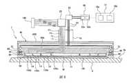
以下,參照圖式說明本發明之實施形態。圖1係顯示研磨裝置之一種實施形態的模式圖。研磨裝置1係化學機械性研磨晶圓、基板、面板等工件之裝置。如圖1所示,該研磨裝置1具備:支撐具有研磨面2a之研磨墊2的研磨台5;對研磨面2a按壓工件W之研磨頭7;將研磨液(例如含研磨粒之漿液)供給至研磨面2a的研磨液供給噴嘴8;及控制研磨裝置1之動作的動作控制部10。研磨頭7係以可在其下面保持工件W之方式構成。工件W具有被研磨膜。Hereinafter, embodiments of the present invention will be described with reference to the drawings. Fig. 1 is a schematic diagram showing an embodiment of the polishing device. The
動作控制部10具備:儲存程式之記憶裝置10a;及按照程式中包含之命令執行運算的運算裝置10b。記憶裝置10a具備RAM等之主記憶裝置;及硬碟機(HDD)、固態硬碟(SSD)等之輔助記憶裝置。運算裝置10b之例可舉出CPU(中央處理裝置)、GPU(圖形處理器)。不過,動作控制部10之具體構成不限定於此等之例。The
動作控制部10由至少1台電腦構成。前述至少1台電腦亦可係1台伺服器或複數台伺服器。動作控制部10亦可係邊緣伺服器,亦可係連接於網際網路或區域網路等之通信網路的雲端伺服器,或是亦可係設置於網路內之霧運算裝置(閘道器、霧伺服器、路由器等)。動作控制部10亦可係藉由網際網路或區域網路等之通信網路而連接的複數個伺服器。例如,動作控制部10亦可係邊緣伺服器與雲端伺服器之組合。The
研磨裝置1進一步具備:支軸14;連結於支軸14之上端的研磨頭搖動臂16;可旋轉地支撐於研磨頭搖動臂16之自由端的研磨頭軸桿18;及使研磨頭7以其軸心為中心而旋轉之旋轉馬達20。旋轉馬達20固定於研磨頭搖動臂16,並經由皮帶及滑輪等構成之轉矩傳送機構(無圖示)而連結於研磨頭軸桿18。研磨頭7固定於研磨頭軸桿18之下端。旋轉馬達20經由上述轉矩傳送機構使研磨頭軸桿18旋轉,研磨頭7與研磨頭軸桿18一起旋轉。因此,研磨頭7係藉由旋轉馬達20將其軸心作為中心而在箭頭指示之方向旋轉。研磨頭7之軸心與研磨頭軸桿18的軸心一致。The
旋轉馬達20與作為檢測研磨頭7之旋轉角度的旋轉角度檢測器之旋轉編碼器22連結。該旋轉編碼器22係以檢測旋轉馬達20之旋轉角度的方式構成。旋轉馬達20之旋轉角度與研磨頭7的旋轉角度一致。因此,藉由旋轉編碼器22所檢測之旋轉馬達20的旋轉角度相當於研磨頭7的旋轉角度。旋轉編碼器22連接於動作控制部10,將從旋轉編碼器22輸出之旋轉馬達20的旋轉角度之檢測值(亦即,研磨頭7之旋轉角度的檢測值)送至動作控制部10。The
研磨裝置1進一步具備使研磨墊2及研磨台5分別以此等之軸心為中心而旋轉的旋轉馬達21。旋轉馬達21配置於研磨台5之下方,研磨台5經由旋轉軸5a而連結於旋轉馬達21。研磨台5及研磨墊2可藉由旋轉馬達21在將旋轉軸5a作為中心而箭頭指示的方向旋轉。研磨墊2及研磨台5之軸心與旋轉軸5a的軸心一致。研磨墊2貼合於研磨台5之墊支撐面5b。研磨墊2之露出面構成研磨晶圓等之工件W的研磨面2a。The polishing
研磨頭軸桿18藉由升降機構24可對研磨頭搖動臂16相對地上下移動,藉由該研磨頭軸桿18之上下移動,研磨頭7可對研磨頭搖動臂16及研磨台5相對地上下移動。在研磨頭軸桿18之上端安裝有旋轉連接器23及旋轉接頭25。The polishing
使研磨頭軸桿18及研磨頭7升降之升降機構24具備:可旋轉地支撐研磨頭軸桿18之軸承26;固定軸承26之橋接器28;安裝於橋接器28之滾珠螺桿機構32;藉由支柱30而支撐之支撐台29;及固定於支撐台29之伺服馬達38。支撐伺服馬達38之支撐台29經由支柱30而連結於研磨頭搖動臂16。The
滾珠螺桿機構32具備:連結於伺服馬達38之螺旋軸32a;及該螺旋軸32a螺合之螺帽32b。螺帽32b固定於橋接器28。研磨頭軸桿18與橋接器28成為一體而升降(上下移動)。因此,當伺服馬達38驅動滾珠螺桿機構32時,橋接器28上下移動,藉此研磨頭軸桿18及研磨頭7上下移動。The
升降機構24發揮用於調節研磨頭7對研磨台5之相對高度的研磨頭定位機構之功能。研磨工件W時, 升降機構24使研磨頭7位於預定之高度,在該高度保持研磨頭7狀態下,研磨頭7對研磨墊2之研磨面2a按壓工件W。The
研磨裝置1具備使研磨頭搖動臂16以支軸14為中心而回轉的臂回轉馬達17。該臂回轉馬達17使研磨頭搖動臂16回轉時,研磨頭7移動至與研磨頭軸桿18垂直的方向。臂回轉馬達17可使研磨頭7在研磨台5上方之研磨位置、與研磨台5外側的裝載/卸載位置之間移動。The polishing
準備研磨之工件W在裝載/卸載位置藉由裝載/卸載裝置39而安裝於研磨頭7,然後移動至研磨位置。研磨後之工件W從研磨位置移動至裝載/卸載位置,在裝載/卸載位置藉由裝載/卸載裝置39而從研磨頭7取出。圖1係模式顯示裝載/卸載裝置39,裝載/卸載裝置39之位置及構成並無特別限定,只要可達成希望的目的即可。The workpiece W to be polished is mounted on the polishing
研磨裝置1具備作為檢測在工件W之周方向的方向之指向檢測器的凹槽對準器40。另外,本圖之凹槽對準器40係獨立地配置於研磨裝置1中,不過亦可與裝載/卸載裝置39一體配置。凹槽對準器40係用於檢測形成於工件W緣部之凹槽(缺口)的裝置。凹槽對準器40之具體性構成並無特別限定,只要係可檢測凹槽者即可。一例為凹槽對準器40係使工件W旋轉,而且將雷射光照射於工件W之緣部,並藉由受光部檢測反射之雷射光的光學式凹槽檢測器,並以在凹槽位置從受光之雷射光強度變化來檢測凹槽之位置的方式構成。其他例係使工件W旋轉,而且從靠近工件W緣部之噴嘴將純水等液體之噴流供給至工件W的緣部,檢測朝向噴嘴流動之液體壓力或流量的液體式凹槽檢測器,並以在凹槽位置從液體之壓力或流量變化來檢測凹槽之位置的方式構成。The polishing
凹槽之檢測,亦即在工件W周方向之方向的檢測係在研磨工件W之前執行。檢測凹槽之目的為瞭解及修正工件W之配置對後述之壓電元件的配置狀態。亦可在將工件W保持於研磨頭7之前執行凹槽的檢測。或是,亦可在將工件W保持於研磨頭7的狀態下執行。例如,在將工件W對研磨頭7保持之前實施凹槽檢測時,在裝載/卸載位置以凹槽對準器40檢測工件W之凹槽位置。而後,亦可以檢測出之凹槽位置變成研磨頭7的特定位置之方式,使研磨頭7旋轉後,以裝載/卸載裝置將工件W送交研磨頭7,並以吸附等方式使工件W保持於研磨頭7。The detection of the groove, that is, the detection of the direction in the circumferential direction of the workpiece W is performed before the workpiece W is polished. The purpose of detecting the groove is to understand and correct the arrangement of the workpiece W to the arrangement state of the piezoelectric element described later. It is also possible to perform the detection of the groove before holding the workpiece W in the polishing
此時,凹槽對準器40連接於動作控制部10。動作控制部10係以將工件W之凹槽位置與研磨頭7的旋轉角度相關連之方式構成。更具體而言,動作控制部10依據藉由凹槽對準器40所檢測之凹槽位置,來指定研磨頭7之旋轉角度的基準位置,並將其旋轉角度之基準位置記憶於記憶裝置10a中。而且,亦將藉由凹槽對準器40所檢測之凹槽位置而且記憶於記憶裝置10a,藉由比較此等基準位置與凹槽位置,動作控制部10可依據研磨頭7之旋轉角度的基準位置特定在工件W表面上的位置。At this time, the
而且,例如藉由旋轉馬達20使研磨頭7旋轉某個角度程度,以工件W之凹槽位置對研磨頭7的基準位置變成指定角度之方式修正後,以裝載/卸載裝置送交工件W而保持於研磨頭7。此時,若事先依據後述之壓電元件的配置來設定研磨頭7之旋轉角度的基準位置時,研磨頭7可在工件W對應於壓電元件之特定配置的狀態下保持工件W。Moreover, for example, the grinding
工件W之研磨進行如下。工件W在將其被研磨面向下狀態下保持於研磨頭7。使研磨頭7及研磨台5分別旋轉,而且從設於研磨台5上方之研磨液供給噴嘴8供給研磨液(例如,含研磨粒之漿液)至研磨墊2的研磨面2a上。研磨墊2以其中心軸線為中心而與研磨台5一體地旋轉。研磨頭7藉由升降機構24移動至指定之高度。再者,研磨頭7於維持在上述指定高度之情況下,將工件W按壓於研磨墊2之研磨面2a。工件W與研磨頭7一體地旋轉。亦即,工件W係以與研磨頭7相同速度旋轉。在研磨墊2之研磨面2a上存在研磨液的狀態下,將工件W滑動接觸於研磨墊2之研磨面2a。工件W之表面藉由研磨液之化學性作用、與研磨液所含之研磨粒或研磨墊2的機械性作用之組合而被研磨。The grinding of the workpiece W is performed as follows. The workpiece W is held by the polishing
研磨裝置1具備測量研磨面2a上之工件W的膜厚之膜厚感測器42。膜厚感測器42係以生成直接或間接顯示工件W之膜厚的膜厚指標值之方式構成。該膜厚指標值依工件W之膜厚而變化。膜厚指標值亦可係表示工件W之膜厚本身的值,或是,亦可係換算成膜厚前之物理量或信號值。The polishing
膜厚感測器42之例可舉出渦電流感測器、光學式膜厚感測器。膜厚感測器42設置於研磨台5中,並與研磨台5一體地旋轉。更具體而言,膜厚感測器42係以每當研磨台5旋轉一圈時,穿越研磨面2a上之工件W,而且在工件W之複數個測量點測量膜厚的方式構成。複數個測量點之膜厚作為膜厚指標值而從膜厚感測器42輸出,膜厚指標值送至動作控制部10。動作控制部10係以依據膜厚指標值控制研磨頭7之動作的方式構成。Examples of the
動作控制部10從膜厚感測器42所輸出之膜厚指標值製作工件W之膜厚輪廓。工件W之膜厚輪廓係膜厚指標值的分布。動作控制部10係以消除所獲得之工件W現在的膜厚輪廓與目標膜厚輪廓之差的方式控制研磨頭7之動作。工件W之目標膜厚輪廓預先儲存於動作控制部10的記憶裝置10a中。工件W現在的膜厚輪廓之例可舉出以圖1所示之研磨裝置1研磨前的工件W之初期膜厚輪廓;及以圖1所示之研磨裝置1研磨工件W時從膜厚感測器42所輸出之膜厚指標值而製作的膜厚輪廓。初期膜厚輪廓例如由藉由無圖示之獨立型之膜厚測量裝置所取得的膜厚測量值、或是藉由具備膜厚感測器之其他研磨裝置1所取得的膜厚測量值來製作。初期膜厚輪廓儲存於動作控制部10之記憶裝置10a中。The
圖2係顯示包含圖1所示之研磨頭7的研磨頭系統之一種實施形態的剖面圖。如圖2所示,研磨頭系統包含:研磨頭7、動作控制部10、及驅動電壓施加裝置50。研磨頭7係以將工件W按壓於研磨墊2之研磨面2a的方式構成。研磨頭7具備:固定於研磨頭軸桿18之下端的載體45;及保持於載體45之複數個壓電元件47。研磨頭7剛性固定於研磨頭軸桿18之下端,研磨頭7對研磨頭軸桿18之角度固定。複數個壓電元件47位於工件W之背面側。FIG. 2 is a cross-sectional view showing an embodiment of the polishing head system including the polishing
載體45具有:保持複數個壓電元件47之殼體45A;及可裝卸地安裝於殼體45A之凸緣45B。凸緣45B藉由無圖示之螺絲而固定於殼體45A。亦可將用於維修之蓋子設於凸緣45B,不過無圖示。拆卸蓋子時,使用者可進入壓電元件47。凸緣45B之蓋子在更換壓電元件47或調節壓電元件47之位置等需要維修時拆卸。The
研磨頭7具備可將複數個按壓力獨立地施加於工件W之複數個致動器。致動器可舉出油壓汽缸/馬達等油壓式致動器、如氣壓馬達或氣壓汽缸之氣壓式致動器、如電動馬達之電力式致動器或使用後述壓電元件之致動器、使用磁偏元件之磁偏致動器或如線性馬達之電磁式致動器或小型活塞等。The polishing
本實施形態可將複數個按壓力獨立地施加於工件W之複數個致動器係採用複數個壓電元件47。壓電元件47通過電力線51而電性連接於驅動電壓施加裝置50。壓電元件47藉由作為驅動源之驅動電壓施加裝置50而工作。電力線51經由旋轉連接器23而延伸。驅動電壓施加裝置50係以具備:電源部50a;及將須施加於壓電元件47之電壓的指令值送至電源部50a的電壓控制部50b;並將電壓分別獨立地施加於複數個壓電元件47之方式構成。In this embodiment, a plurality of
驅動電壓施加裝置50連接於動作控制部10。動作控制部10係以決定須分別施加於複數個壓電元件47之電壓的複數個指令值,並將決定之複數個指令值送至驅動電壓施加裝置50之電壓控制部50b的方式構成。電壓控制部50b係以按照此等指令值對電源部50a輸出指令,電源部50a施加指定電壓至各個壓電元件47之方式構成。另外,電源部50a由直流電源、交流電源、或是可設定電壓圖案之可程式電源的任何一個或其組合而構成。The driving
研磨頭7進一步具備:分別連結於複數個壓電元件47之複數個按壓構件54;保持複數個按壓構件54之保持構件56;及測量複數個壓電元件47分別產生之複數個按壓力的複數個按壓力測量裝置57。複數個按壓構件54及保持構件56與工件W之背面側相對。The polishing
驅動電壓施加裝置50對複數個壓電元件47施加電壓時,此等壓電元件47朝向按壓構件54而伸長。該壓電元件47之伸長經由按壓構件54產生將工件W對研磨墊2之研磨面2a按壓的按壓力。因此,施加了電壓之壓電元件47可將複數個按壓力獨立地施加於工件W,可以不同之按壓力將工件W之複數個部位(區域)對研磨面2a按壓。When the driving
本實施形態之複數個按壓構件54的端面係構成用於對研磨面2a按壓工件W之按壓面54a。複數個按壓構件54之按壓面54a與工件W之背面側接觸。按壓面54a亦可由矽膠等之彈性構件而構成。按壓面54a之形狀的具體例可舉出正多角形、圓形、扇形、圓弧形狀、橢圓形、及此等形狀之組合。從按壓面54a之中心至各頂點的距離相等之正多角形之例可舉出正三角形、正四方形、正六角形。The end surfaces of the plurality of pressing
保持構件56可將複數個按壓構件54在有限之範圍內移動地保持此等按壓構件54。更具體而言,保持構件56藉由遊隙限制按壓構件54在上下方向及水平方向移動之範圍,並容許複數個按壓構件54在上下方向移動。藉由該保持構件56限制複數個按壓構件54在與工件W之按壓方向垂直的方向之移動範圍。因此,由於限制按壓構件54在上下方向之移動,因此按壓構件54可防止過度的撞擊或力道傳導至壓電元件47。一種實施形態亦可省略複數個按壓構件54與保持構件56,而以複數個壓電元件47直接對工件W之背面加壓,而對研磨墊2之研磨面2a按壓工件W。The holding
研磨頭系統進一步具備研磨頭7可藉由真空吸引而保持工件W之真空管線60。該真空管線60經由旋轉接頭25延伸而與研磨頭7之工件接觸面56a連通。更具體而言,真空管線60之一端在研磨頭7之工件接觸面56a開口,真空管線60之另一端連結於真空泵浦等的真空源62。在真空管線60中安裝有真空閥61。真空閥61係致動器驅動型開閉閥(例如電動閥、電磁閥、空氣操作閥),且連接於動作控制部10。真空閥61之動作藉由動作控制部10來控制。當動作控制部10打開真空閥61時,真空管線60在研磨頭7之工件接觸面56a上形成真空,藉此研磨頭7可藉由真空吸引而將工件W保持於研磨頭7之工件接觸面56a。The polishing head system is further provided with a
一種實施形態亦可在工件W研磨中,為了防止工件W對研磨頭7相對旋轉(亦即,為了固定工件W對研磨頭7之相對位置),而藉由真空管線60在研磨頭7之工件接觸面56a上形成真空,並藉由真空吸引而將工件W保持於研磨頭7之工件接觸面56a。另外,本圖係在工件W之中央配置1個真空管線60,不過亦可設置在工件接觸面56a中複數處開口之複數個真空管線60。An embodiment can also be used in the grinding of the workpiece W. In order to prevent the workpiece W from rotating relative to the grinding head 7 (that is, to fix the relative position of the workpiece W to the grinding head 7), the
研磨頭7進一步具備:配置於複數個壓電元件47之外側的固定構件66;及連結於固定構件66之複數個壓電元件72。各壓電元件72係用於對研磨墊2之研磨面2a按壓固定構件66的致動器。固定構件66係以包圍工件W、複數個按壓構件54、及複數個壓電元件47之方式配置。本實施形態之工件W係圓形,且固定構件66整體係包圍工件W之環狀。另外,固定構件66以PPS(聚苯硫醚)及PEEK(聚醚醚酮)等樹脂材料形成,此外,亦可在與研磨面2a之接觸面上形成用於調整研磨液之流入的溝。The polishing
壓電元件72與壓電元件47同樣地保持於載體45之殼體45A。研磨頭7進一步具備:分別連結於複數個壓電元件72之複數個連結構件80;保持複數個連結構件80之保持構件85;及測量複數個壓電元件72分別產生之複數個按壓力的複數個按壓力測量裝置88。保持構件85係環狀,且固定於載體45。複數個壓電元件72經由複數個連結構件80及複數個按壓力測量裝置88而連結於固定構件66。The
壓電元件72電性連接於驅動電壓施加裝置50。動作控制部10係以決定須分別施加於複數個壓電元件72之電壓的複數個指令值,並將所決定之複數個指令值送至驅動電壓施加裝置50之電壓控制部50b的方式構成。電壓控制部50b係以藉由按照此等指令值對電源部50a輸出指令,而將指定之電壓施加於各個壓電元件72的方式構成。The
對壓電元件72施加電壓時,壓電元件72將按壓力測量裝置88及連結構件80朝向研磨墊2之研磨面2a推動,連結構件80以依施加於壓電元件72之電壓的按壓力對研磨墊2之研磨面2a按壓固定構件66。按壓力之測量值從按壓力測量裝置88送至動作控制部10。動作控制部10依據按壓力之測量值調整須施加於壓電元件72之電壓的指令值。When a voltage is applied to the
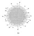
圖3係從下方觀看按壓構件54、壓電元件72、及固定構件66時之模式圖。如圖3所示,壓電元件72係以包圍按壓構件54(及壓電元件47)之方式配置。固定構件66沿著工件W(圖3中未顯示)之外周部而配置。壓電元件72沿著固定構件66而排列。FIG. 3 is a schematic diagram when the pressing
圖3所示之例係蜂巢狀排列複數個按壓構件54,各按壓構件54之按壓面54a係正六角形。從圖3瞭解構成蜂巢排列之正六角形的按壓面54a可使鄰接之按壓面54a間的間隙最小。再者,正六角形比正三角形及正四方形亦具有各頂點之角度大,且不易發生應力集中的優點。In the example shown in FIG. 3, a plurality of pressing
圖3所示之各按壓構件54連結於各壓電元件47。因此,圖3所示之按壓構件54的排列與壓電元件47的排列實質地相同。複數個壓電元件47及複數個按壓構件54沿著研磨頭7之徑方向及周方向而分布。因此,研磨頭系統可精密地控制工件W之膜厚輪廓。特別是研磨頭系統可在工件W之周方向消除膜厚偏差。Each pressing
按壓構件54之排列不限於圖3所示之例,亦可係格柵狀、同心圓狀、交錯狀等其他排列。此外,各按壓構件54之按壓面54a亦不限於正六角形,亦可係圓形、矩形狀、扇形、或此等之組合。The arrangement of the
如圖4所示,一種實施形態係研磨頭7亦可具備複數個固定構件66。複數個固定構件66係以包圍工件W、複數個按壓構件54、及複數個壓電元件47之方式排列。複數個壓電元件72經由複數個連結構件80(參照圖5)及複數個按壓力測量裝置88(參照圖5)而分別連結於複數個固定構件66。As shown in FIG. 4, in one embodiment, the polishing
圖5係顯示圖2所示之壓電元件72、保持構件85、連結構件80、及固定構件66的剖面圖。參照圖5之以下的說明亦適用於圖4之實施形態。如圖5所示,載體45之殼體45A具有複數個階梯孔90,複數個壓電元件72分別收容於此等階梯孔90中。各壓電元件72具有止動突起72a。藉由止動突起72a抵接於階梯孔90之階部90a,達成壓電元件72對載體45之相對定位。FIG. 5 is a cross-sectional view showing the
本實施形態之各按壓力測量裝置88係與壓電元件72及連結構件80直向配置。更具體而言,各按壓力測量裝置88係配置於壓電元件72與連結構件80之間。如此配置之按壓力測量裝置88可個別地測量壓電元件72分別產生的複數個按壓力。按壓力測量裝置88之配置不限於圖5所示的實施形態。只要可個別地測量壓電元件72分別產生之複數個按壓力,按壓力測量裝置88亦可配置於固定構件66與連結構件80之間,或是亦可配置於連結構件80旁邊。Each pressing
按壓力測量裝置88亦可以將所測量之按壓力[N]換算成壓力[Pa]的方式構成。按壓力測量裝置88之例可舉出連結於複數個壓電元件72之負載傳感器、壓電板。壓電板係以具有複數個壓電感測器,依施加於此等壓電板之力而產生電壓,並將電壓值換算成力或壓力之方式構成。The pressing
複數個連結構件80之端面連接於固定構件66。保持構件85可將複數個連結構件80在有限範圍內移動地保持此等連結構件80。更具體而言,各連結構件80具有:位於其上端及下端之突出部80b, 80c;及位於此等突出部80b, 80c之間的中間部80d。中間部80d之寬度比突出部80b, 80c的寬度小。保持構件85具有支撐部85a,其係具有與中間部80d一定之遊隙,並可移動地支撐連結構件80。各連結構件80之突出部80b, 80c與保持構件85之支撐部85a藉由遊隙限制連結構件80在上下方向及水平方向移動之範圍,並容許各連結構件80在上下方向移動。保持構件85之支撐部85a限制連結構件80在與固定構件66之按壓方向垂直的方向之移動範圍。由於限制連結構件80在上下方向移動,因此連結構件80可防止過度之撞擊或力道傳導至壓電元件72。The end surfaces of the plurality of connecting
被固定構件66推動之研磨墊2變形,研磨墊2之一部分在固定構件66周圍向上方隆起。藉此,藉由在工件W之邊緣部研磨墊2的接觸壓力增加,可提高對工件W之邊緣部的研磨率。採用本實施形態時,由於複數個壓電元件72可獨立地對研磨墊2之研磨面2a按壓固定構件66,因此可精密地控制工件W邊緣部之研磨率分布。The
其次,說明研磨頭7之動作的一例。動作控制部10計算工件W現在之膜厚輪廓、與預先儲存於記憶裝置10a中的目標膜厚輪廓之差,來製作目標研磨量在工件W之被研磨面的分布。再者,動作控制部10依據所製作之目標研磨量的分布,為了在指定之研磨時間內達成目標研磨量,而決定須施加於壓電元件72及壓電元件47的電壓指令值。例如,動作控制部10從目標研磨量之分布與上述指定的研磨時間製作目標研磨率之分布,並從研磨率相關資料決定可達成目標研磨率之電壓的指令值。研磨率相關資料係顯示研磨率與電壓指令值之關係的資料。Next, an example of the operation of the polishing
動作控制部10將電壓之指令值送至驅動電壓施加裝置50的電壓控制部50b。電壓控制部50b按照此等電壓之指令值輸出指令至電源部50a,電源部50a對壓電元件72及壓電元件47施加指定之電壓,來進行工件W之膜厚輪廓的調整。另外,在工件W之研磨中,例如在各一定時間或研磨台5每一個旋轉週期進行膜厚輪廓之調整。The
研磨頭7之動作的另外例係動作控制部10不製作目標研磨量之分布,而係依據藉由膜厚感測器42所獲得之工件W的現在膜厚輪廓,來決定須施加至壓電元件72及壓電元件47之電壓的指令值。例如,目標膜厚輪廓係平坦之膜厚輪廓時,動作控制部10為了將現在之膜厚輪廓接近平坦的膜厚輪廓,而決定將比現在所施加之電壓高指定的變更量程度之電壓施加至對應於膜厚指標值大之區域的壓電元件72及壓電元件47,並將比現在施加之電壓低指定的變更量程度之電壓施加至對應於膜厚指標值小之區域的壓電元件72及壓電元件47之電壓的指令值。另外,此等電壓之變更量作為參數而預先設定於動作控制部10。Another example of the action of the polishing
返回圖2,本實施形態之各按壓力測量裝置57係與壓電元件47及按壓構件54直向配置。更具體而言,各按壓力測量裝置57係配置於壓電元件47與按壓構件54之間。如此配置之按壓力測量裝置57可個別地測量壓電元件47分別產生之複數個按壓力。按壓力測量裝置57之配置不限於圖2所示的實施形態。只要可個別地測量壓電元件47分別產生之複數個按壓力,按壓力測量裝置57亦可配置於工件W與按壓構件54之間,或是亦可配置於按壓構件54旁邊。Returning to FIG. 2, each pressing
按壓力測量裝置57亦可以將所測量之按壓力[N]換算成壓力[Pa]的方式構成。按壓力測量裝置57之例可舉出連結於複數個壓電元件47之負載傳感器、壓電板。壓電板係以具有複數個壓電感測器,依施加於此等壓電板之力而產生電壓,並將電壓值換算成力或壓力之方式構成。The pressing
對壓電元件47施加電壓時,壓電元件47將按壓力測量裝置57及按壓構件54朝向研磨墊2之研磨面2a推動,按壓構件54以依施加於壓電元件47之電壓的按壓力對研磨面2a按壓工件W對應之部位(區域)。按壓力之測量值從按壓力測量裝置57送至動作控制部10。動作控制部10依據按壓力之測量值調整須施加至壓電元件47之電壓的指令值。When a voltage is applied to the
圖6係顯示研磨頭系統之其他實施形態的剖面圖。由於未特別說明之本實施形態的構成及動作與參照圖1至圖5所說明之實施形態相同,因此省略其重複之說明。Fig. 6 is a cross-sectional view showing another embodiment of the polishing head system. Since the configuration and operation of the present embodiment, which is not specifically described, are the same as those of the embodiment described with reference to FIGS. 1 to 5, the repetitive description thereof will be omitted.
研磨頭系統具備使複數個壓電元件72及整個固定構件66對壓電元件47相對地朝向研磨墊2之研磨面2a移動的固定構件移動裝置100。固定構件移動裝置100具備:在內部形成壓力室102之彈性囊103;連通於壓力室102之氣體供給管線105;及連接於氣體供給管線105之壓力調整器108。複數個壓電元件72可上下移動地支撐於載體45之殼體45A。The polishing head system includes a fixed
彈性囊103設置於研磨頭7之載體45中,彈性囊103之一部分保持於載體45。彈性囊103由可伸縮之柔軟的彈性材料構成。彈性囊103沿著整個固定構件66而延伸。本實施形態之固定構件66係環狀,且彈性囊103亦係環狀。The
氣體供給管線105經由旋轉接頭25而延伸至壓縮氣體供給源110。壓縮氣體供給源110亦可係設置於配置有研磨裝置1之工廠作為應用設備的壓縮氣體供給源,或是亦可係輸送壓縮氣體之泵浦。壓縮空氣等之壓縮氣體係從壓縮氣體供給源110通過氣體供給管線105而供給至壓力室102中。The
壓力調整器108係以安裝於氣體供給管線105,來調節壓力室102中之壓縮氣體壓力的方式構成。壓力調整器108連接於動作控制部10,壓力調整器108之動作(亦即壓力室102中之壓縮氣體的壓力)藉由動作控制部10來控制。更具體而言,動作控制部10將壓力指令值送至壓力調整器108,壓力調整器108係以將壓力室102中之壓力維持在壓力指令值的方式而動作。The
在壓力室102中供給壓縮氣體時,彈性囊103膨脹,而使壓電元件72及整個固定構件66朝向研磨墊2之研磨面2a移動,另外,載體45及作為致動器之壓電元件47的位置不變。因此,固定構件移動裝置100可將與從壓電元件47施加於工件W之按壓力獨立的均勻按壓力施加於壓電元件72及整個固定構件66。When compressed gas is supplied in the
採用本實施形態時,固定構件移動裝置100可使壓電元件72及整個固定構件66朝向研磨墊2之研磨面2a移動,並以均勻之力對研磨面2a按壓固定構件66。再者,複數個壓電元件72可以局部差異之壓力對研磨面2a按壓固定構件66。動作控制部10亦可使固定構件移動裝置100及壓電元件72兩者同時工作,或是亦可僅使其中一方選擇性工作。In this embodiment, the fixed
圖6係以直接推動壓電元件72之方式配置彈性囊103,不過亦可將壓電元件72配置於無圖示之外殼中,並藉由彈性囊103加壓外殼,而使壓電元件72及整個固定構件66朝向研磨墊2之研磨面2a移動。藉由設置外殼,可防止來自彈性囊103之過度的力道直接傳導至壓電元件72。Fig. 6 is the arrangement of the
圖7係顯示研磨頭系統之其他實施形態的剖面圖。由於未特別說明之本實施形態的構成及動作與參照圖1至圖6所說明之實施形態相同,因此省略其重複之說明。Fig. 7 is a cross-sectional view showing another embodiment of the polishing head system. Since the configuration and operation of the present embodiment, which is not specifically described, are the same as those of the embodiment described with reference to FIGS. 1 to 6, the repetitive description thereof will be omitted.
本實施形態之研磨頭系統具備配置於研磨頭7中之電壓分配器121。電壓分配器121具備:將電壓分配至壓電元件47, 72之分歧裝置125;及連接於分歧裝置125之通信裝置128。分歧裝置125及通信裝置128固定於載體45。分歧裝置125經由電力線51及旋轉連接器23而電性連接於驅動電壓施加裝置50之電源部50a。電力通過電力線51而從驅動電壓施加裝置50之電源部50a供給至分歧裝置125,進一步從分歧裝置125分配至壓電元件47, 72。The polishing head system of this embodiment includes a
分歧裝置125通過電力線51及旋轉連接器23連接於驅動電壓施加裝置50之電源部50a,電力從電源部50a供給至分歧裝置125。通信裝置128經由通信線130而連接於動作控制部10。通信線130從通信裝置128經由旋轉連接器23及電壓控制部50b而延伸至動作控制部10。動作控制部10將須施加至壓電元件47及壓電元件72之電壓的指令值送至電壓控制部50b及通信裝置128,通信裝置128將電壓之指令值送至分歧裝置125。分歧裝置125按照從通信裝置128取得之指令值與同樣來自電壓控制部50b的指令值,將從電源部50a所施加之電壓分配並施加於各個壓電元件47及壓電元件72。採用本實施形態時,可減少從壓電元件47, 72延伸至電源部50a之電力線51的數量。The
圖8係顯示研磨頭系統之其他實施形態的剖面圖。由於未特別說明之本實施形態的構成及動作與參照圖1至圖7所說明之實施形態相同,因此省略其重複之說明。Fig. 8 is a cross-sectional view showing another embodiment of the polishing head system. Since the configuration and operation of the present embodiment, which is not specifically described, are the same as those of the embodiment described with reference to FIGS. 1 to 7, the repetitive description thereof will be omitted.
本實施形態將工件W按壓於研磨墊2之研磨面2a的致動器係採用流體壓力式致動器來取代壓電元件47。更具體而言,流體壓力式致動器具備:形成複數個壓力室C1~C4之彈性膜135;分別連通於此等壓力室C1~C4之複數條氣體供給管線F1~F4;及分別連接於此等氣體供給管線F1~F4之複數個壓力調整器R1~R4。彈性膜135之露出面係構成對研磨墊2之研磨面2a按壓工件W的工件接觸面。In this embodiment, the actuator for pressing the workpiece W on the polishing
彈性膜135保持於載體45之下面。該彈性膜135具有同心狀之複數個分隔壁135a~135d。此等分隔壁135a~135d將彈性膜135內側之空間分割成複數個壓力室C1~C4。此等壓力室C1~C4之排列係同心狀。本實施形態係設有4個壓力室C1~C4,不過亦可設置比4個少、或比4個多的壓力式。固定構件66係以包圍彈性膜135及壓力室C1~C4之方式配置。The
氣體供給管線F1~F4經由旋轉接頭25而延伸至壓縮氣體供給源140。壓縮氣體供給源140亦可係設置於配置有研磨裝置1之工廠作為應用設備的壓縮氣體供給源,或是亦可係輸送壓縮氣體之泵浦。壓縮空氣等之壓縮氣體係從壓縮氣體供給源140通過氣體供給管線而供給至壓力室C1~C4中。The gas supply lines F1 to F4 extend to the compressed
壓力調整器R1~R4係以分別安裝於氣體供給管線F1~F4,來獨立地調節壓力室C1~C4中之壓縮氣體的壓力之方式構成。壓力調整器R1~R4連接於動作控制部10,並藉由動作控制部10控制壓力調整器R1~R4之動作(亦即壓力室C1~C4中之壓縮氣體的壓力)。更具體而言,動作控制部10將複數個壓力指令值分別送至壓力調整器R1~R4,壓力調整器R1~R4以維持在壓力室C1~C4中之壓力對應的壓力指令值之方式動作。研磨頭7可以不同之推壓力按壓工件W的不同區域。The pressure regulators R1 to R4 are respectively installed in the gas supply lines F1 to F4 to independently adjust the pressure of the compressed gas in the pressure chambers C1 to C4. The pressure regulators R1 to R4 are connected to the
其次,說明圖8所示之研磨頭7的動作之一例。動作控制部10計算工件W現在之膜厚輪廓、與預先儲存於記憶裝置10a中的目標膜厚輪廓之差,來製作目標研磨量在工件W之被研磨面的分布。再者,動作控制部10依據所製作之目標研磨量的分布,為了在指定之研磨時間內達成目標研磨量,而決定須施加於壓電元件72的電壓指令值、與須送至壓力調整器R1~R4之壓力指令值。例如,動作控制部10從目標研磨量之分布與上述指定的研磨時間製作目標研磨率之分布,並從研磨率相關資料決定可達成目標研磨率之電壓的指令值及壓力指令值。研磨率相關資料包含:顯示研磨率與電壓指令值之關係的資料、及顯示研磨率與壓力指令值之關係的資料。Next, an example of the operation of the polishing
動作控制部10將壓力指令值分別送至壓力調整器R1~R4,並將電壓之指令值送至驅動電壓施加裝置50的電壓控制部50b。壓力調整器R1~R4係以將壓力室C1~C4中之壓力分別維持在壓力指令值的方式動作。電壓控制部50b按照電壓之指令值輸出指令至電源部50a,電源部50a對壓電元件72施加指定之電壓。因此,研磨頭7進行工件W之膜厚輪廓的調整。另外,在工件W之研磨中,例如在各一定時間、或研磨台5每一個旋轉週期進行膜厚輪廓之調整。The
研磨頭7之動作的另外例係動作控制部10不製作目標研磨量之分布,而係依據藉由膜厚感測器42所獲得之工件W的現在膜厚輪廓,來決定須施加至壓電元件72之電壓的指令值、及須送至壓力調整器R1~R4之壓力指令值。例如,目標膜厚輪廓係平坦之膜厚輪廓時,動作控制部10為了將現在之膜厚輪廓接近平坦的膜厚輪廓,而決定將比現在所施加之電壓高指定的變更量程度之電壓施加至對應於膜厚指標值大之區域的壓電元件72,並將比現在施加之電壓低指定的變更量程度之電壓施加至對應於膜厚指標值小之區域的壓電元件72之電壓的指令值。同樣地,動作控制部10決定在對應於膜厚指標值大之區域的壓力室中形成比現在壓力高指定之變更量程度的壓力,並在對應於膜厚指標值小之區域的壓力室中形成比現在壓力低指定之變更量程度的壓力之壓力指令值。另外,此等電壓之變更量及壓力之變更量作為參數而預先設定於動作控制部10。Another example of the action of the polishing
上述實施形態可適當組合。例如,圖6所示之實施形態可適用於圖7所示之實施形態、及圖8所示之實施形態。The above-mentioned embodiments can be combined as appropriate. For example, the embodiment shown in FIG. 6 can be applied to the embodiment shown in FIG. 7 and the embodiment shown in FIG. 8.
本發明除了圓形的工件之外,亦可適用於矩形狀、四方形等多角形狀之工件的研磨。例如,用於研磨四方形工件之研磨頭系統係以包圍四方形之工件的方式構成固定構件。In addition to round workpieces, the present invention can also be applied to polishing workpieces with polygonal shapes such as rectangles and squares. For example, a grinding head system for grinding a square workpiece constitutes a fixed member in a manner that surrounds the square workpiece.
圖9係顯示處理工件之處理系統的一種實施形態之俯視圖。圖示之處理系統100具有:本說明書中說明之研磨處理工件W的研磨裝置1-A~1-C;用於清洗工件W之清洗裝置350-A, 350-B;作為工件W之搬送裝置的機器人400;工件W之裝載埠500;及乾燥裝置600。該系統構成中,處理之工件W放入裝載埠500中。裝載於裝載埠500之工件W藉由機器人400而搬送至研磨裝置1-A~1-C的任何一個進行研磨處理。基板等之工件W亦可以複數個研磨裝置依序進行研磨處理。進行研磨處理後之工件W藉由機器人400搬送至清洗裝置350-A, 350-B的其中一個進行清洗。工件W亦可以清洗裝置350-A, 350-B依序清洗。進行清洗後之工件W搬送至乾燥裝置600進行乾燥處理。乾燥後之工件W再度返回裝載埠500。Fig. 9 is a top view showing an embodiment of a processing system for processing workpieces. The
上述實施形態係以具有本發明所屬之技術領域的一般知識者可實施本發明為目的而記載者。熟悉本技術之業者當然可形成上述實施形態之各種修改例,本發明之技術性思想亦可適用於其他實施形態。因此,本發明不限定於記載之實施形態,而係依按照藉由申請專利範圍所定義之技術性思想的最廣範圍來解釋者。The above-mentioned embodiments are described for the purpose of being able to carry out the present invention by those who have general knowledge in the technical field to which the present invention belongs. Of course, those skilled in the art can form various modifications of the above-mentioned embodiments, and the technical idea of the present invention can also be applied to other embodiments. Therefore, the present invention is not limited to the described embodiments, but is interpreted in accordance with the broadest scope of technical ideas defined by the scope of the patent application.
1,1-A~1-C:研磨裝置2:研磨墊2a:研磨面5:研磨台5a:旋轉軸5b:墊支撐面7:研磨頭8:研磨液供給噴嘴10:動作控制部10a:記憶裝置10b:運算裝置14:支軸16:研磨頭搖動臂17:臂回轉馬達18:研磨頭軸桿20:旋轉馬達21:旋轉馬達22:旋轉編碼器23:旋轉連接器24:升降機構25:旋轉接頭26:軸承28:橋接器29:支撐台30:支柱32:滾珠螺桿機構32a:螺旋軸32b:螺帽38:伺服馬達39:裝載/卸載裝置40:凹槽對準器42:膜厚感測器45:載體45A:殼體45B:凸緣47:壓電元件50:驅動電壓施加裝置50a:電源部50b:電壓控制部51:電力線54:按壓構件54a:按壓面56:保持構件56a:工件接觸面57:按壓力測量裝置60:真空管線61:真空閥62:真空源66:固定構件72:壓電元件72a:止動突起80:連結構件80b,80c:突出部80d:中間部85:保持構件85a:支撐部88:按壓力測量裝置90:階梯孔90a:階部100:固定構件移動裝置102:壓力室103:彈性囊105:氣體供給管線108:壓力調整器110:壓縮氣體供給源121:電壓分配器125:分歧裝置128:通信裝置130:通信線135:彈性膜135a~135d:分隔壁140:壓縮氣體供給源350-A,350-B:清洗裝置400:機器人(搬送裝置)500:裝載埠600:乾燥裝置1000:處理系統C1~C4:壓力室F1~F4:氣體供給管線R1~R4:壓力調整器W:工件1,1-A~1-C: Grinding device2: Grinding pad2a: Grinding surface5: Grinding table5a: Rotation axis5b: Pad support surface7: Grinding head8: Slurry supply nozzle10: Motion Control Department10a: Memory device10b: Computing device14: fulcrum16: Grinding head swing arm17: Arm swing motor18: Grinding head shaft20: Rotating motor21: Rotating motor22: Rotary encoder23: Rotating connector24: Lifting mechanism25: Rotary joint26: Bearing28: Bridge29: support table30: Pillar32: Ball screw mechanism32a: Spiral shaft32b: Nut38: Servo motor39: Loading/unloading device40: Groove aligner42: Film thickness sensor45: carrier45A: Shell45B: flange47: Piezoelectric element50: Drive voltage applying device50a: Power supply department50b: Voltage control unit51: Power line54: pressing member54a: pressing surface56: Holding member56a: Workpiece contact surface57: Press pressure measuring device60: Vacuum line61: Vacuum valve62: Vacuum source66: fixed component72: Piezoelectric element72a: Stop protrusion80: connecting member80b, 80c: protrusion80d: middle part85: holding member85a: Support88: Press pressure measuring device90: step hole90a: Stage100: Fixed component moving device102: pressure chamber103: Elastic sac105: Gas supply line108: Pressure Regulator110: Compressed gas supply source121: Voltage divider125: divergence device128: communication device130: communication line135: Elastic membrane135a~135d: Partition wall140: Compressed gas supply source350-A, 350-B: cleaning device400: Robot (transport device)500: load port600: Drying device1000: Processing systemC1~C4: Pressure chamberF1~F4: Gas supply pipelineR1~R4: Pressure regulatorW: Workpiece
圖1係顯示研磨裝置之一種實施形態的模式圖。圖2係顯示包含圖1所示之研磨頭的研磨頭系統之一種實施形態的剖面圖。圖3係從下方觀看按壓構件、壓電元件、及固定構件時之模式圖。圖4係從下方觀看按壓構件、壓電元件、及複數個固定構件時之模式圖。圖5係顯示圖2所示之壓電元件、保持構件、連結構件、及固定構件的剖面圖。圖6係顯示研磨頭系統之其他實施形態的剖面圖。圖7係顯示研磨頭系統之其他實施形態的剖面圖。圖8係顯示研磨頭系統之其他實施形態的剖面圖。圖9係顯示處理工件之處理系統的一種實施形態之俯視圖。Fig. 1 is a schematic diagram showing an embodiment of the polishing device.FIG. 2 is a cross-sectional view showing an embodiment of a polishing head system including the polishing head shown in FIG. 1.Fig. 3 is a schematic diagram when the pressing member, the piezoelectric element, and the fixing member are viewed from below.Fig. 4 is a schematic diagram when the pressing member, the piezoelectric element, and the plurality of fixing members are viewed from below.Fig. 5 is a cross-sectional view showing the piezoelectric element, holding member, connecting member, and fixing member shown in Fig. 2.Fig. 6 is a cross-sectional view showing another embodiment of the polishing head system.Fig. 7 is a cross-sectional view showing another embodiment of the polishing head system.Fig. 8 is a cross-sectional view showing another embodiment of the polishing head system.Fig. 9 is a top view showing an embodiment of a processing system for processing workpieces.
2:研磨墊2: Grinding pad
2a:研磨面2a: Grinding surface
7:研磨頭7: Grinding head
10:動作控制部10: Motion Control Department
10a:記憶裝置10a: Memory device
10b:運算裝置10b: Computing device
18:研磨頭軸桿18: Grinding head shaft
23:旋轉連接器23: Rotating connector
25:旋轉接頭25: Rotary joint
45:載體45: carrier
45A:殼體45A: Shell
45B:凸緣45B: flange
47:壓電元件47: Piezoelectric element
50:驅動電壓施加裝置50: Drive voltage applying device
50a:電源部50a: Power supply department
50b:電壓控制部50b: Voltage control unit
51:電力線51: Power line
54:按壓構件54: pressing member
54a:按壓面54a: pressing surface
56:保持構件56: Holding member
56a:工件接觸面56a: Workpiece contact surface
57:按壓力測量裝置57: Press pressure measuring device
60:真空管線60: Vacuum line
61:真空閥61: Vacuum valve
62:真空源62: Vacuum source
66:固定構件66: fixed component
72:壓電元件72: Piezoelectric element
80:連結構件80: connecting member
85:保持構件85: holding member
88:按壓力測量裝置88: Press pressure measuring device
W:工件W: Workpiece
Claims (21)
Translated fromChineseApplications Claiming Priority (2)
| Application Number | Priority Date | Filing Date | Title |
|---|---|---|---|
| JP2020056240AJP7365282B2 (en) | 2020-03-26 | 2020-03-26 | Polishing head system and polishing equipment |
| JP2020-056240 | 2020-03-26 |
Publications (2)
| Publication Number | Publication Date |
|---|---|
| TW202135983Atrue TW202135983A (en) | 2021-10-01 |
| TWI881078B TWI881078B (en) | 2025-04-21 |
Family
ID=77809393
Family Applications (1)
| Application Number | Title | Priority Date | Filing Date |
|---|---|---|---|
| TW110109986ATWI881078B (en) | 2020-03-26 | 2021-03-19 | Grinding head system and grinding device |
Country Status (6)
| Country | Link |
|---|---|
| US (1) | US11673222B2 (en) |
| JP (1) | JP7365282B2 (en) |
| KR (1) | KR102794245B1 (en) |
| CN (1) | CN113442054A (en) |
| SG (1) | SG10202102760UA (en) |
| TW (1) | TWI881078B (en) |
Families Citing this family (11)
| Publication number | Priority date | Publication date | Assignee | Title |
|---|---|---|---|---|
| KR102733621B1 (en) | 2020-06-24 | 2024-11-25 | 어플라이드 머티어리얼스, 인코포레이티드 | Polishing carrier head with piezoelectric pressure control |
| KR102719957B1 (en)* | 2020-07-08 | 2024-10-22 | 어플라이드 머티어리얼스, 인코포레이티드 | Multi-tooth, self-regulating retaining ring |
| US20230063687A1 (en)* | 2021-08-27 | 2023-03-02 | Taiwan Semiconductor Manufacturing Company Limited | Apparatus for polishing a wafer |
| JP7626344B2 (en) | 2021-09-22 | 2025-02-07 | 日亜化学工業株式会社 | Light emitting device and method for manufacturing the same |
| US20230219189A1 (en)* | 2022-01-07 | 2023-07-13 | Applied Materials, Inc. | Apparatus and method for selective material removal during polishing |
| KR20240158978A (en)* | 2022-03-14 | 2024-11-05 | 가부시키가이샤 에바라 세이사꾸쇼 | Substrate polishing device, substrate polishing method, polishing device and polishing method |
| CN114800052B (en)* | 2022-03-18 | 2023-09-26 | 大连理工大学 | A grinding method for improving the surface shape of optical wafers |
| KR102806293B1 (en)* | 2023-04-05 | 2025-05-13 | 유상욱 | Compressing Apparatus for Semiconductor Chips |
| US20250269488A1 (en)* | 2024-02-28 | 2025-08-28 | Applied Materials, Inc. | Electrical connection for chemical mechanical polishing carrier head |
| CN118305711B (en)* | 2024-06-06 | 2024-08-06 | 浙江求是半导体设备有限公司 | Polishing machine and polishing state monitoring method |
| CN119772706A (en)* | 2025-02-26 | 2025-04-08 | 中国工程物理研究院激光聚变研究中心 | A multi-point boost control device for plane processing of optical elements |
Family Cites Families (40)
| Publication number | Priority date | Publication date | Assignee | Title |
|---|---|---|---|---|
| JPH09225820A (en) | 1996-02-23 | 1997-09-02 | Hitachi Ltd | Polishing equipment |
| JPH10128655A (en) | 1996-10-31 | 1998-05-19 | Toshiba Corp | Polishing equipment |
| US5868896A (en)* | 1996-11-06 | 1999-02-09 | Micron Technology, Inc. | Chemical-mechanical planarization machine and method for uniformly planarizing semiconductor wafers |
| KR100475845B1 (en)* | 1997-04-04 | 2005-06-17 | 도쿄 세이미츄 코퍼레이션 리미티드 | Polishing device |
| US6110025A (en)* | 1997-05-07 | 2000-08-29 | Obsidian, Inc. | Containment ring for substrate carrier apparatus |
| US5888120A (en)* | 1997-09-29 | 1999-03-30 | Lsi Logic Corporation | Method and apparatus for chemical mechanical polishing |
| US5997384A (en)* | 1997-12-22 | 1999-12-07 | Micron Technology, Inc. | Method and apparatus for controlling planarizing characteristics in mechanical and chemical-mechanical planarization of microelectronic substrates |
| JP2000127024A (en)* | 1998-10-27 | 2000-05-09 | Toshiba Corp | Polishing apparatus and polishing method |
| JP2000246628A (en) | 1999-02-23 | 2000-09-12 | Ebara Corp | Substrate holding device and polishing device |
| TW436382B (en)* | 1999-03-12 | 2001-05-28 | Mitsubishi Materials Corp | Wafer holding head, wafer polishing apparatus, and method for making wafers |
| US6290584B1 (en)* | 1999-08-13 | 2001-09-18 | Speedfam-Ipec Corporation | Workpiece carrier with segmented and floating retaining elements |
| US6325696B1 (en)* | 1999-09-13 | 2001-12-04 | International Business Machines Corporation | Piezo-actuated CMP carrier |
| JP3753577B2 (en)* | 1999-11-16 | 2006-03-08 | 株式会社荏原製作所 | Substrate holding device and polishing apparatus provided with the substrate holding device |
| US6558232B1 (en)* | 2000-05-12 | 2003-05-06 | Multi-Planar Technologies, Inc. | System and method for CMP having multi-pressure zone loading for improved edge and annular zone material removal control |
| US6776695B2 (en)* | 2000-12-21 | 2004-08-17 | Lam Research Corporation | Platen design for improving edge performance in CMP applications |
| US6863771B2 (en)* | 2001-07-25 | 2005-03-08 | Micron Technology, Inc. | Differential pressure application apparatus for use in polishing layers of semiconductor device structures and methods |
| US6579151B2 (en)* | 2001-08-02 | 2003-06-17 | Taiwan Semiconductor Manufacturing Co., Ltd | Retaining ring with active edge-profile control by piezoelectric actuator/sensors |
| DE10303407A1 (en)* | 2003-01-27 | 2004-08-19 | Friedrich-Schiller-Universität Jena | Method and device for high-precision processing of the surface of an object, in particular for polishing and lapping semiconductor substrates |
| US7131891B2 (en)* | 2003-04-28 | 2006-11-07 | Micron Technology, Inc. | Systems and methods for mechanical and/or chemical-mechanical polishing of microfeature workpieces |
| US7150673B2 (en)* | 2004-07-09 | 2006-12-19 | Ebara Corporation | Method for estimating polishing profile or polishing amount, polishing method and polishing apparatus |
| JP2006048302A (en) | 2004-08-03 | 2006-02-16 | Sony Corp | Piezoelectric composite device, manufacturing method thereof, handling method thereof, control method thereof, input / output device and electronic apparatus |
| US7048621B2 (en)* | 2004-10-27 | 2006-05-23 | Applied Materials Inc. | Retaining ring deflection control |
| US8083571B2 (en)* | 2004-11-01 | 2011-12-27 | Ebara Corporation | Polishing apparatus |
| JP2008528300A (en)* | 2005-01-21 | 2008-07-31 | 株式会社荏原製作所 | Substrate polishing method and apparatus |
| TWI386989B (en)* | 2005-02-25 | 2013-02-21 | Ebara Corp | Polishing apparatus and polishing method |
| JP4762647B2 (en)* | 2005-02-25 | 2011-08-31 | 株式会社荏原製作所 | Polishing apparatus and polishing method |
| CN101007396A (en)* | 2006-01-24 | 2007-08-01 | 联华电子股份有限公司 | Polishing head applied to chemical mechanical polishing process and chemical mechanical polishing method |
| JP5464820B2 (en)* | 2007-10-29 | 2014-04-09 | 株式会社荏原製作所 | Polishing equipment |
| JP5148259B2 (en)* | 2007-12-14 | 2013-02-20 | 株式会社 東北テクノアーチ | Processing equipment |
| US20090311945A1 (en)* | 2008-06-17 | 2009-12-17 | Roland Strasser | Planarization System |
| JP5980476B2 (en)* | 2010-12-27 | 2016-08-31 | 株式会社荏原製作所 | Polishing apparatus and polishing method |
| EP2771968B1 (en)* | 2011-10-25 | 2017-12-13 | Robert Bosch GmbH | Actuating device |
| WO2013112764A1 (en)* | 2012-01-25 | 2013-08-01 | Applied Materials, Inc. | Retaining ring monitoring and control of pressure |
| WO2014144861A1 (en)* | 2013-03-15 | 2014-09-18 | Applied Materials, Inc. | Polishing system with front side pressure control |
| JP6145342B2 (en)* | 2013-07-12 | 2017-06-07 | 株式会社荏原製作所 | Film thickness measuring apparatus, film thickness measuring method, and polishing apparatus equipped with film thickness measuring apparatus |
| WO2015159973A1 (en)* | 2014-04-18 | 2015-10-22 | 株式会社荏原製作所 | Substrate processing device, substrate processing system, and substrate processing method |
| US9878421B2 (en)* | 2014-06-16 | 2018-01-30 | Applied Materials, Inc. | Chemical mechanical polishing retaining ring with integrated sensor |
| JP6562779B2 (en) | 2015-09-02 | 2019-08-21 | 株式会社荏原製作所 | Polishing apparatus and polishing method |
| JP6585445B2 (en)* | 2015-09-28 | 2019-10-02 | 株式会社荏原製作所 | Polishing method |
| JP6818614B2 (en)* | 2017-03-31 | 2021-01-20 | 株式会社荏原製作所 | Substrate processing equipment and substrate processing system including substrate processing equipment |
- 2020
- 2020-03-26JPJP2020056240Apatent/JP7365282B2/enactiveActive
- 2021
- 2021-03-18SGSG10202102760Upatent/SG10202102760UA/enunknown
- 2021-03-19USUS17/206,652patent/US11673222B2/enactiveActive
- 2021-03-19TWTW110109986Apatent/TWI881078B/enactive
- 2021-03-22KRKR1020210036408Apatent/KR102794245B1/enactiveActive
- 2021-03-24CNCN202110313239.4Apatent/CN113442054A/enactivePending
Also Published As
| Publication number | Publication date |
|---|---|
| SG10202102760UA (en) | 2021-10-28 |
| US11673222B2 (en) | 2023-06-13 |
| TWI881078B (en) | 2025-04-21 |
| KR102794245B1 (en) | 2025-04-14 |
| CN113442054A (en) | 2021-09-28 |
| JP7365282B2 (en) | 2023-10-19 |
| US20210308823A1 (en) | 2021-10-07 |
| KR20210120860A (en) | 2021-10-07 |
| JP2021154421A (en) | 2021-10-07 |
Similar Documents
| Publication | Publication Date | Title |
|---|---|---|
| TW202135983A (en) | Polishing head system and polishing apparatus | |
| CN113134785B (en) | Grinding head system and grinding device | |
| JP6827663B2 (en) | Substrate polishing device | |
| TWI500082B (en) | Plasma reactor with tiltable overhead rf inductive source | |
| TWI867252B (en) | Substrate carrier for polishing surface of substrate and method of polishing substrate | |
| US6183342B1 (en) | Polishing apparatus | |
| JP4762647B2 (en) | Polishing apparatus and polishing method | |
| US10556314B2 (en) | Head height adjustment device and substrate processing apparatus provided with head height adjustment device | |
| TW202201513A (en) | Polishing method, polishing device, and computer-readable recording medium recording program | |
| JP2021154471A (en) | Method for detecting variation in height of movable surface of actuator | |
| US20240253181A1 (en) | Method of creating responsiveness profile of polishing rate of workpiece, polishing method, and computer-readable storage medium storing program | |
| CN115135449A (en) | Deformable substrate chuck | |
| TW202421358A (en) | Top ring and substrate processing device | |
| US20240198480A1 (en) | Method of creating responsive profile of polishing rate of workpiece, polishing method, and polishing apparatus | |
| US20240424636A1 (en) | Control of platen shape in chemical mechanical polishing | |
| WO2004012249A1 (en) | Polishing device | |
| WO2024142757A1 (en) | Polishing method, polishing device and recording medium | |
| JP2025037737A (en) | Processing head and substrate processing apparatus | |
| CN117581336A (en) | Polishing method and polishing apparatus |