TW202134716A - An optical fiber connector and a multi-fiber fiber optic connector - Google Patents
An optical fiber connector and a multi-fiber fiber optic connectorDownload PDFInfo
- Publication number
- TW202134716A TW202134716ATW110100982ATW110100982ATW202134716ATW 202134716 ATW202134716 ATW 202134716ATW 110100982 ATW110100982 ATW 110100982ATW 110100982 ATW110100982 ATW 110100982ATW 202134716 ATW202134716 ATW 202134716A
- Authority
- TW
- Taiwan
- Prior art keywords
- key
- connector
- housing
- displaceable
- groove
- Prior art date
Links
- 239000013307optical fiberSubstances0.000titleclaimsabstractdescription55
- 239000000835fiberSubstances0.000titleclaimsabstractdescription38
- 230000008859changeEffects0.000claimsabstractdescription7
- 230000002441reversible effectEffects0.000abstractdescription2
- 238000005516engineering processMethods0.000description12
- 238000000034methodMethods0.000description9
- 238000003780insertionMethods0.000description6
- 230000037431insertionEffects0.000description6
- 230000013011matingEffects0.000description6
- 239000000463materialSubstances0.000description5
- 230000003287optical effectEffects0.000description4
- 230000005540biological transmissionEffects0.000description2
- 230000000903blocking effectEffects0.000description2
- 210000000078clawAnatomy0.000description2
- 238000006073displacement reactionMethods0.000description2
- 239000002184metalSubstances0.000description2
- 238000012986modificationMethods0.000description2
- 230000004048modificationEffects0.000description2
- 229920000642polymerPolymers0.000description2
- 230000000712assemblyEffects0.000description1
- 238000000429assemblyMethods0.000description1
- 230000008901benefitEffects0.000description1
- 238000006243chemical reactionMethods0.000description1
- 150000001875compoundsChemical class0.000description1
- 230000000994depressogenic effectEffects0.000description1
- 238000010586diagramMethods0.000description1
- 210000005069earsAnatomy0.000description1
- 239000000203mixtureSubstances0.000description1
- 239000002086nanomaterialSubstances0.000description1
- 239000011253protective coatingSubstances0.000description1
- 230000000630rising effectEffects0.000description1
- 239000007787solidSubstances0.000description1
Images


Classifications
- G—PHYSICS
- G02—OPTICS
- G02B—OPTICAL ELEMENTS, SYSTEMS OR APPARATUS
- G02B6/00—Light guides; Structural details of arrangements comprising light guides and other optical elements, e.g. couplings
- G02B6/24—Coupling light guides
- G02B6/36—Mechanical coupling means
- G02B6/38—Mechanical coupling means having fibre to fibre mating means
- G02B6/3807—Dismountable connectors, i.e. comprising plugs
- G02B6/3895—Dismountable connectors, i.e. comprising plugs identification of connection, e.g. right plug to the right socket or full engagement of the mating parts
- G—PHYSICS
- G02—OPTICS
- G02B—OPTICAL ELEMENTS, SYSTEMS OR APPARATUS
- G02B6/00—Light guides; Structural details of arrangements comprising light guides and other optical elements, e.g. couplings
- G02B6/24—Coupling light guides
- G02B6/36—Mechanical coupling means
- G02B6/38—Mechanical coupling means having fibre to fibre mating means
- G02B6/3807—Dismountable connectors, i.e. comprising plugs
- G02B6/3873—Connectors using guide surfaces for aligning ferrule ends, e.g. tubes, sleeves, V-grooves, rods, pins, balls
- G02B6/3885—Multicore or multichannel optical connectors, i.e. one single ferrule containing more than one fibre, e.g. ribbon type
- G—PHYSICS
- G02—OPTICS
- G02B—OPTICAL ELEMENTS, SYSTEMS OR APPARATUS
- G02B6/00—Light guides; Structural details of arrangements comprising light guides and other optical elements, e.g. couplings
- G02B6/24—Coupling light guides
- G02B6/36—Mechanical coupling means
- G02B6/38—Mechanical coupling means having fibre to fibre mating means
- G02B6/3807—Dismountable connectors, i.e. comprising plugs
- G02B6/381—Dismountable connectors, i.e. comprising plugs of the ferrule type, e.g. fibre ends embedded in ferrules, connecting a pair of fibres
- G02B6/3826—Dismountable connectors, i.e. comprising plugs of the ferrule type, e.g. fibre ends embedded in ferrules, connecting a pair of fibres characterised by form or shape
- G02B6/3831—Dismountable connectors, i.e. comprising plugs of the ferrule type, e.g. fibre ends embedded in ferrules, connecting a pair of fibres characterised by form or shape comprising a keying element on the plug or adapter, e.g. to forbid wrong connection
- G—PHYSICS
- G02—OPTICS
- G02B—OPTICAL ELEMENTS, SYSTEMS OR APPARATUS
- G02B6/00—Light guides; Structural details of arrangements comprising light guides and other optical elements, e.g. couplings
- G02B6/24—Coupling light guides
- G02B6/36—Mechanical coupling means
- G02B6/38—Mechanical coupling means having fibre to fibre mating means
- G02B6/3807—Dismountable connectors, i.e. comprising plugs
- G02B6/381—Dismountable connectors, i.e. comprising plugs of the ferrule type, e.g. fibre ends embedded in ferrules, connecting a pair of fibres
- G02B6/3825—Dismountable connectors, i.e. comprising plugs of the ferrule type, e.g. fibre ends embedded in ferrules, connecting a pair of fibres with an intermediate part, e.g. adapter, receptacle, linking two plugs
- G—PHYSICS
- G02—OPTICS
- G02B—OPTICAL ELEMENTS, SYSTEMS OR APPARATUS
- G02B6/00—Light guides; Structural details of arrangements comprising light guides and other optical elements, e.g. couplings
- G02B6/24—Coupling light guides
- G02B6/36—Mechanical coupling means
- G02B6/38—Mechanical coupling means having fibre to fibre mating means
- G02B6/3807—Dismountable connectors, i.e. comprising plugs
- G02B6/389—Dismountable connectors, i.e. comprising plugs characterised by the method of fastening connecting plugs and sockets, e.g. screw- or nut-lock, snap-in, bayonet type
- G02B6/3893—Push-pull type, e.g. snap-in, push-on
Landscapes
- Physics & Mathematics (AREA)
- General Physics & Mathematics (AREA)
- Optics & Photonics (AREA)
- Mechanical Coupling Of Light Guides (AREA)
- Details Of Connecting Devices For Male And Female Coupling (AREA)
Abstract
Description
Translated fromChinese本發明係有關於具有可變極性的光纖連接器。The present invention relates to an optical fiber connector with variable polarity.
企業和個人消費者對頻帶寬度的需求持續地經歷指數性的成長。為有效率且經濟地滿足此需求,資料中心必須以低損耗預算來達到超高密度纜線配設。光纖已變成資料中心用來滿足資料容量和傳輸速度之成長需求的標準配線媒體。The demand for bandwidth of enterprises and individual consumers continues to experience exponential growth. In order to meet this demand efficiently and economically, data centers must achieve ultra-high-density cabling with a low-loss budget. Optical fiber has become the standard distribution medium used by data centers to meet the growing demand for data capacity and transmission speed.
個別的光纖係極小。例如,即使具有保護塗層,光纖的直徑可為只有約250微米(僅為一人類頭髮直徑的大約4倍)。因此,數百條光纖能被裝在纜線中,其會占用相對較少的空間。但是,針對纖線之間的連接,該等光纖係以連接器終結。許多光纖可被列設在單一連接器內。例如,多光纖連接器譬如使用多光纖推接/拉斷(MPO)技術者可包含並連接12或24條光纖。連接器,譬如MPO式連接器,通常包含一殼體部份其含有一套環會終結該等光纖的末端。套環通常係用來扣持該等光纖的末端以連接該等光纖。一種可與MPO式連接器一起使用的光學套環係為可機械式傳輸(MT)套環。Individual optical fiber systems are extremely small. For example, even with a protective coating, the diameter of an optical fiber can be only about 250 microns (only about 4 times the diameter of a human hair). Therefore, hundreds of optical fibers can be installed in the cable, which takes up relatively little space. However, for the connection between fibers, these fibers are terminated with connectors. Many optical fibers can be arranged in a single connector. For example, a multi-fiber connector such as a multi-fiber push-on/pull-off (MPO) technology can contain and connect 12 or 24 optical fibers. Connectors, such as MPO-type connectors, usually include a housing part that contains a set of rings that terminate the ends of the optical fibers. The ferrule is usually used to hold the ends of the optical fibers to connect the optical fibers. One type of optical ferrule system that can be used with MPO-type connectors is a mechanically transferable (MT) ferrule.
典型地,MPO連接器係接合在一起來將一光纖纜線的傳輸光徑連接於另一光纖纜線或裝置,且該連接可藉將該等MPO連接器插入一MPO配接器中而被完成。一配接器通常包含一殼體,或一殼體的一部份,具有至少一孔口其係構製成能容納並固持一連接器,以促成該連接器套環與另一連接器之套環或其它裝置的光連接。配接器可被用來促成一框架內的連接。該“框架”乙詞若被用於此係泛指一用以容納電氣組件或切換組件的容裝結構。Typically, MPO connectors are joined together to connect the transmission path of one fiber optic cable to another fiber optic cable or device, and the connection can be made by inserting these MPO connectors into an MPO adapter. Finish. An adapter usually includes a housing, or a part of a housing, with at least one orifice configured to receive and hold a connector to facilitate the connection between the connector collar and another connector Optical connection of collars or other devices. Adapters can be used to facilitate connections within a frame. If the term "frame" is used here, it generally refers to a housing structure for accommodating electrical components or switching components.
由於使用預終結式光纖總成的結果,在平行光纖連線中保持極性的議題逐漸變得愈加重要。簡而言之,極性會維持傳送器和接收器之間的妥確連續性。為能確保連接器係與一配接器正確地配接,該連接器和配接器典型會包含固定的鍵合細構等,其允許該連接器通常僅能以一配接構形來與該配接器配接。雖此所具的優點係能防止一具有錯誤極性的連接,但此亦會使其難以在現場來改變該連接的極性。As a result of the use of pre-terminated optical fiber assemblies, the issue of maintaining polarity in parallel optical fiber connections has gradually become more important. In short, polarity maintains proper continuity between transmitter and receiver. In order to ensure that the connector is correctly mated with an adapter, the connector and the adapter typically include a fixed bonding structure, etc., which allows the connector to usually only be mated with a mating configuration. This adapter mates. Although this has the advantage of preventing a connection with a wrong polarity, it also makes it difficult to change the polarity of the connection in the field.
因此,仍有需要一種多光纖的光纖連接器,其具有在現場容易改變該連接器之極性的可調變性。Therefore, there is still a need for a multi-fiber optical fiber connector, which has the tunability that can easily change the polarity of the connector in the field.
為使一多光纖的光纖連接器之極性可被改變,該連接器之一殼體可被構製成包含一可移除的鍵,其可被定位在該殼體上的不同位置。要改變該極性時,該鍵可被由一位置移至另一位置。In order to allow the polarity of a multi-fiber fiber optic connector to be changed, a housing of the connector can be constructed to include a removable key that can be positioned at different positions on the housing. To change the polarity, the key can be moved from one position to another.
一種光纖連接器,包含: 一套環;一內殼體設成圍繞該套環的至少一部份,該內殼體具有一前端部及沿一軸相隔開的一後端部,該內殼體的該前端部構製成被插入一光纖配接器中,該內殼體具有一第一側及一相反的第二側,該第一側和該第二側分別設置於該套環的相對側,該第一側包含一第一槽,該第一槽通過該內殼體的該前端部沿該軸由一後端朝一前端延伸,該第二側包含一第二槽,該第二槽通過該內殼體的該前端部沿該軸由一後端朝一前端延伸;一外殼體設成圍繞該內殼體的至少一部分;至少一對準鍵構製成:可移除地於一第一位置連接於該內殼體的該第一側,該第一位置對應於該連接器的一第一極性,其中當該至少一對準鍵於該第一位置附接於該內殼體的該第一側時該至少一對準鍵的一部分被接收於在該內殼體的該第一前端部的該第一槽中;以及可移除地於一第二位置連接於該內殼體的該第二側,該第二位置對應於該連接器的一第二極性,其中當該至少一對準鍵於該第二位置附接於該內殼體的該第二側時該至少一對準鍵的一部分被接收於在該內殼體的該第一前端部的該第二槽中;其中該至少一對準鍵構製成相對於該內殼體和外殼體兩者移動以將該連接器在該第一極性和該第二極性之間變換。An optical fiber connector includes: a sleeve ring; an inner shell is arranged to surround at least a part of the ferrule, the inner shell has a front end and a rear end spaced apart along an axis, the inner shell The front end is configured to be inserted into an optical fiber adapter, the inner housing has a first side and an opposite second side, the first side and the second side are respectively disposed on the opposite side of the ferrule Side, the first side includes a first groove, the first groove extends from a rear end to a front end along the shaft through the front end of the inner housing, the second side includes a second groove, the second groove The front end of the inner casing extends from a rear end to a front end along the shaft; an outer casing is provided to surround at least a part of the inner casing; at least one alignment key is configured to be removably attached to a first A position is connected to the first side of the inner housing, the first position corresponds to a first polarity of the connector, and when the at least one alignment key is attached to the inner housing at the first position A part of the at least one alignment key at the first side is received in the first groove in the first front end of the inner housing; and is removably connected to the inner housing at a second position The second side of the connector, the second position corresponds to a second polarity of the connector, wherein when the at least one alignment key is attached to the second side of the inner housing in the second position, the at least one A part of the alignment key is received in the second groove of the first front end of the inner housing; wherein the at least one alignment key is configured to move relative to both the inner housing and the outer housing to move The connector changes between the first polarity and the second polarity.
一種多光纖的光纖連接器,包含:一套環有多條光纖被撐持其中;一外殼體;一內殼體設成圍繞該套環的至少一部份以及該外殼體部分地環繞該內殼體,該內殼體包含:一第一端可供被插入一光纖配接器中;一第二端設成相反於該第一端;及至少一第一壁部由該第一端向該第二端延伸,及一第二壁部相反於該第一壁部並由該第一端向該第二端延伸; 其中各該第一壁部和第二壁部皆有一內表面設成朝向該套環,及一外表面設成向外離開該套環; 及該內殼體會在一由該第一端至該第二端的方向界定一縱軸, 一第一縱向槽形成於該第一壁部的該外表面中和一第二縱向槽形成於該第二壁部的該外表面中,各該第一縱向槽和第二縱向槽沿該縱軸延伸;一第一可移位的鍵,該第一可移位的鍵被連接於該第一壁部使得該第一可移位的鍵的至少一部分被接收於該第一縱向槽中,該第一可移位的鍵在一前置的第一鍵位置和一後置的第一鍵位置之間沿該第一縱向槽選擇性地可移動;一第二可移位的鍵,該第二可移位的鍵被連接於該第二壁部使得該第二可移位的鍵的至少一部分被接收於該第二縱向槽中,該第二可移位的鍵在一前置的第二鍵位置和一後置的第二鍵位置之間沿該第二縱向槽選擇性地可移動;其中該連接器構製成扣持該第一可移位的鍵在各該前置的第一鍵位置和後置的第一鍵位置以阻止該第一可移位的鍵由該前置的第一鍵位置和該後置的第一鍵位置的各自之一者滑掉;以及其中該連接器構製成容許該第一可移位的鍵由在該前置的第一鍵位置和該後置的第一鍵位置之間的位置滑向該前置的第一鍵位置和該後置的第一鍵位置的至少之一者;其中該連接器構製成扣持該第二可移位的鍵在各該前置的第二鍵位置和後置的第二鍵位置以阻止該第二可移位的鍵由該前置的第二鍵位置和該後置的第二鍵位置的各自之一者滑掉;以及其中該連接器構製成容許該第二可移位的鍵由在該前置的第二鍵位置和該後置的第二鍵位置之間的位置滑向該前置的第二鍵位置和該後置的第二鍵位置的至少之一者。A multi-fiber optical fiber connector, comprising: a sleeve with a plurality of optical fibers supported therein; an outer shell; an inner shell arranged to surround at least a part of the ferrule, and the outer shell partially surrounds the inner shell Body, the inner housing includes: a first end for being inserted into an optical fiber adapter; a second end arranged opposite to the first end; and at least one first wall portion facing the first end from the first end The second end extends, and a second wall portion is opposite to the first wall portion and extends from the first end to the second end; wherein each of the first wall portion and the second wall portion has an inner surface facing toward The collar and an outer surface are arranged to leave the collar outward; and the inner casing defines a longitudinal axis in a direction from the first end to the second end, and a first longitudinal groove is formed in the first The outer surface of the wall portion and a second longitudinal groove are formed in the outer surface of the second wall portion, each of the first longitudinal groove and the second longitudinal groove extending along the longitudinal axis; a first displaceable Key, the first displaceable key is connected to the first wall portion such that at least a part of the first displaceable key is received in the first longitudinal groove, and the first displaceable key is at a A front first key position and a rear first key position are selectively movable along the first longitudinal groove; a second displaceable key, the second displaceable key is connected to The second wall portion enables at least a part of the second displaceable key to be received in the second longitudinal groove, the second displaceable key at a front second key position and a rear second key position The two key positions are selectively movable along the second longitudinal groove; wherein the connector is configured to buckle the first displaceable key at each of the front first key position and the rear first key position Key position to prevent the first displaceable key from sliding off each of the front first key position and the rear first key position; and wherein the connector is configured to allow the first The shiftable key slides from the position between the front first key position and the rear first key position to at least one of the front first key position and the rear first key position One; wherein the connector is configured to buckle the second displaceable key in each of the front second key position and the rear second key position to prevent the second displaceable key from the Each of the front second key position and the rear second key position slides off; and wherein the connector is configured to allow the second displaceable key to be replaced by the second key in the front The position between the position and the rear second key position slides to at least one of the front second key position and the rear second key position.
一多光纖的光纖連接器包含一套環會有多數條光纖被撐持其中,及一殼體圍繞該套環的至少一部份佈設。該殼體有一第一端可被插入一光纖配接器,一第二端設成相反於該第一端,及至少一第一壁部由該第一端延伸朝向該第二端,及一第一壁部相反於該第一壁部並由該第一端延伸朝向該第二端,其中各該第一壁部和第二壁部皆具有一內表面朝該套環佈設及一外表面設成向外離開該套環。該殼體會在一由該第一端至該第二端的方向界定一縱軸,一橫軸正交於該縱軸,及一垂直中心線穿過該第一和第二壁部。該連接器亦包含一鍵構製成被可移除地附接於該第一壁部來界定一第一配鍵構形可供該第一端僅能以一第一定向插入該配接器中來相對於該配接器界定一第一極性,或附接於該第二壁部來界定一第二配鍵構形可供該第一端僅能以一第二定向插入該配接器中來相對於該配接器界定一第二極性,其中該第二極性係相反於該第一極性。該鍵包含一第一端構製成可與該殼體銜接而鄰近該第一殼端,而當可移除地附接於該第一壁部或該第二壁部時,能阻止該第一鍵端在至少一由該殼體側向離開的方向相對於該殼體移動;及一第二端設成縱向地離開該第一端,且構製成可被可移除地附接於該殼體之一第二位置,其係朝該殼體的第二端縱向地相隔於該殼體的第一端,而當可移除地附接於該第一壁部或該第二壁部時,能阻止該鍵在至少一沿該殼體的縱向相對於該殼體移動。A multi-fiber optical fiber connector includes a ring in which a plurality of optical fibers are supported, and a shell is arranged around at least a part of the ring. The housing has a first end that can be inserted into an optical fiber adapter, a second end is arranged opposite to the first end, and at least one first wall portion extends from the first end toward the second end, and a The first wall portion is opposite to the first wall portion and extends from the first end toward the second end, wherein each of the first wall portion and the second wall portion has an inner surface arranged toward the collar and an outer surface Set to leave the collar outwards. The shell defines a longitudinal axis in a direction from the first end to the second end, a horizontal axis is orthogonal to the longitudinal axis, and a vertical center line passes through the first and second wall portions. The connector also includes a key configured to be removably attached to the first wall to define a first keying configuration for the first end to be inserted into the mating only in a first orientation The device defines a first polarity relative to the adapter, or is attached to the second wall portion to define a second keying configuration, so that the first end can only be inserted into the adapter in a second orientation The device defines a second polarity relative to the adapter, wherein the second polarity is opposite to the first polarity. The key includes a first end configured to be engaged with the housing and adjacent to the first housing end, and when removably attached to the first wall portion or the second wall portion, the first end can be prevented A key end moves relative to the housing in at least one direction away from the housing laterally; and a second end is set to be longitudinally away from the first end, and is configured to be removably attached to A second position of the housing, which is longitudinally spaced from the first end of the housing toward the second end of the housing, and when removably attached to the first wall or the second wall The part can prevent the key from moving relative to the housing in at least one longitudinal direction of the housing.
在一實施例中,一用於一光纖連接器的殼體包含一第一端可被插入一光纖配接器,及一第二端設成相反於該第一端,且該殼體會界定一縱向由該第一端至該第二端,及一橫向正交於該縱向。該殼體亦包含至少一第一壁部由該第一端朝該第二端延伸,及一第二壁部相反於該第一壁部並由該第一端朝該第二端延伸,其中各該第一壁部和該第二壁部皆具有一外表面設成向外離開該套環。該殼體亦包含一鍵構製成能被可移除地附接於該第一壁部來界定一第一配鍵構形,可供該第一端僅能以一第一定向插入該配接器中來相對於該配接器界定一第一構態,或附接於該第二壁部來界定一第二配鍵構形可供該第一端僅能以一第二定向插入該配接器中來相對於該配接器界定一第二構態。該鍵包含一扣入固緊物及一扭轉鎖定固緊物之一者,構製成可與該第一壁部或第二壁部銜抵,且各該第一壁部和第二壁部皆包含一開孔構製成可承納該扣入固緊物或該轉入固緊物,而來可釋地扣持該鍵與該第一壁部或該第二壁部。In one embodiment, a housing for an optical fiber connector includes a first end that can be inserted into an optical fiber adapter, and a second end is arranged opposite to the first end, and the housing defines a The longitudinal direction is from the first end to the second end, and a transverse direction is orthogonal to the longitudinal direction. The housing also includes at least a first wall portion extending from the first end toward the second end, and a second wall portion opposite to the first wall portion and extending from the first end toward the second end, wherein Each of the first wall portion and the second wall portion has an outer surface arranged to be outwardly away from the collar. The housing also includes a key configured to be removably attached to the first wall portion to define a first keying configuration, allowing the first end to be inserted into the The adapter defines a first configuration relative to the adapter, or is attached to the second wall portion to define a second keying configuration for the first end to be inserted only in a second orientation The adapter defines a second configuration relative to the adapter. The key includes one of a snap-in fastener and a twist-lock fastener, and is configured to engage with the first wall portion or the second wall portion, and each of the first wall portion and the second wall portion Both include an opening structure configured to receive the buckled-in fastener or the transfer-in fastener, so as to releasably buckle the key and the first wall portion or the second wall portion.
在一實施例中,一方法係被提供用以在一多光纖的光纖連接器與一構製成可承接該連接器的對應配接器之間切換其極性構態。該連接器具有一連接器殼體包含一第一端可被插入該配接器中,一第二端設成相反於該第一端,及至少第一和第二可動的可移位鍵可沿該殼體移位於一鄰近該第一端的第一位置與一朝該第二端佈設的第二位置之間。該等第一和第二鍵之一者可在其第一位置,而該等第一和第二鍵之另一者可在其第二位置,來為該光纖連接器提供一第一極性。該方法包含滑動地移位該第一鍵由其對應的第一或第二位置至該第一和第二位置的另一者,及滑動地移位該第二鍵由其對應的第一或第二位置至該第一和第二位置的另一者,而來為該光纖連接器提供一相反的第二極性。In one embodiment, a method is provided to switch its polarity configuration between a multi-fiber optical fiber connector and a corresponding adapter configured to accept the connector. The connector has a connector housing that includes a first end that can be inserted into the adapter, a second end that is set opposite to the first end, and at least first and second movable displaceable keys along which The casing is moved between a first position adjacent to the first end and a second position arranged toward the second end. One of the first and second keys can be in its first position, and the other of the first and second keys can be in its second position to provide a first polarity for the optical fiber connector. The method includes slidingly shifting the first key from its corresponding first or second position to the other of the first and second positions, and slidingly shifting the second key from its corresponding first or From the second position to the other of the first and second positions, an opposite second polarity is provided for the optical fiber connector.
若被用於此,該“光纖”乙詞係意圖適用於所有類型的單模式和多模式光導,包括一或更多的裸光纖,塗層光纖,鬆管光纖,緊襯光纖,帶式光纖,撓曲效能光纖,撓曲遲鈍光纖,奈米結構光纖,或用以傳輸光訊號的任何其它權宜物。一多光纖的光纜線包含多數條該等光纖。該等纜線可依它們的特定用途而具有各種的名稱,並可被視為“主幹纜線”或“幹線”,當使用一選擇的極性連接於用以 對跨接纜線形成連接的光纖模組時。為將纜線連接在一起或與其它光纖裝置連接,一纜線的終結端可包含一連接器。一連接器可包含一殼體結構構製成能與一配接器連接並交互作用。一配接器,在一簡單形式中,可包含二對準的孔口用以在其內對準光纖連接器來端對端地對準並連接光纖。如於此所述,該等連接器和配接器可被視為多光纖連接器及多光纖配接器。If used here, the term "optical fiber" is intended to apply to all types of single-mode and multi-mode light guides, including one or more bare fibers, coated fibers, loose tube fibers, tightly lined fibers, and ribbon fibers. , Flexural performance fiber, flexurally dull fiber, nanostructure fiber, or any other expedients used to transmit optical signals. A multi-fiber optical cable includes a plurality of these optical fibers. These cables can have various names depending on their specific uses, and can be regarded as "trunk cables" or "trunk cables" when connected to the optical fibers used to connect the jumper cables with a selected polarity Module time. To connect cables together or with other fiber optic devices, the terminating end of a cable may include a connector. A connector may include a housing structure configured to be connected to and interact with an adapter. An adapter, in a simple form, may contain two aligned apertures for aligning the optical fiber connector therein to align and connect the optical fibers end-to-end. As described herein, these connectors and adapters can be regarded as multi-fiber connectors and multi-fiber adapters.
為將纜線連接在一起或與其它光纖裝置連接,一纜線的終結端可包含一連接器。一連接器可包含一殼體結構構製成能與一配接器連接並交互作用。一配接器,在一簡單形式中,可包含二對準的孔口用以在其內對準光纖連接器來端對端地對準並連接光纖。如於此所述,該等連接器和配接器可被視為多光纖連接器及多光纖配接器。To connect cables together or with other fiber optic devices, the terminating end of a cable may include a connector. A connector may include a housing structure configured to be connected to and interact with an adapter. An adapter, in a simple form, may contain two aligned apertures for aligning the optical fiber connector therein to align and connect the optical fibers end-to-end. As described herein, these connectors and adapters can be regarded as multi-fiber connectors and multi-fiber adapters.
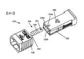
雖以下描述係指向MPO配接器和具有MT光纖套環的MPO連接器,但所述的實施例亦可適用於其它類型的配接器、連接器和套環等。一MPO連接器10和配接器12之一實施例係概示於圖1中。該連接器10之一第一端可包含一套環14其可為一多光纖套環如所示。此外,該連接器10可被附接於一光纖纜線15a和纜線引出罩15b(僅示意地示出),其可由該連接器之一第二端伸出。Although the following description is directed to MPO adapters and MPO connectors with MT fiber ferrules, the described embodiments can also be applied to other types of adapters, connectors, ferrules, and the like. An embodiment of the
一配接器12可包含一第一端16具有一第一塞入孔口18,其內可供容納一光纖連接器10的該套環端,並可包含一第二端20具有另一塞入孔口22(不可見),其內可供容納另一MPO光纖連接器,或其它類型的光纖裝置。An
為將一MPO連接器10扣持在各該孔口18、22內,該等孔口內可被設具一連接器夾,其可由二彈性凸耳24a、24b形成,係構製成朝外移位以供一連接器10插入該等孔口18、22中及移除出其外,並回復至它們實質上的初始位置來將一連接器銜接且扣持於該等孔口內。一配接器12可被構製成能被安裝在一框板上,並可包含安裝凸緣等以例如藉螺絲等來安裝該配接器。In order to buckle an
一連接器10可包含一內殼體26其可包圍該套環14。在所示實施例中,套環14係為母型-一配對的連接器可具有一公型套環具有二導銷會套入該母套環的承接孔中。一連接器10亦可包含一外殼體構件28,其可被圍繞該內殼體26可滑動地配設而鄰近該連接器10的第二端。為提供該配接器12內的光纖纜線之一預定的對準,該內殼體可包含一對準鍵30,其係構製成能套入該配接器的鍵槽32內。例如,在所示實施例中,該連接器10或配接器12之一者將必須被繞其軸線旋轉180°來對準該鍵30與該槽32。內殼體26可滑入孔口18中直到凸耳24a、24b卡抵於該內殼體的槽隙34a、34b中,該外殼體28可被朝該第二端移動,以容許該等凸耳24a、24b能卡抵於槽隙34a、34b中,並將該等凸耳扣持於該等槽隙內,該外殼體可以朝該第一端滑回並越過該等凸耳。該外殼體28可藉彈簧(例如圖6D中所示)或另擇類型的偏壓裝置而被朝該第一端偏壓。A
圖2A和2B呈示二種不同的連接對準模式用以提供該兩種不同的極性模式。圖2A可被示為代表可被稱為一“正常”極性者,其中該連接器10a的1號光纖可與連接器10b的1號光纖配接,且類似地,該連接器10a的12號光纖可與連接器10b的12號光纖對準。為了此種對準,該鍵30可被設成鄰近該套環的A面,且該配接器可被依此鍵合,而使槽32等(圖1)設在該配接器12內之對應的相對表面中。要倒反連接器10a、10b之間的連接之極性時,如圖2B中所示,該連 接器10b之鍵30的鍵位置必須被改變至相反表面用以在一配接器12中倒反對準,使該連接器10a的1號光纖可與連接器10b的12號光纖配接,且同樣地,該連接器10a的12號光纖可與連接器10b的1號光纖配接。或者,該連接器10a的鍵30可被改變,或在另一實施例中,一不同類型的配接器可被使用,其中該等槽32可在該配接器12內的同一內表面上被對準。2A and 2B show two different connection alignment modes to provide the two different polarity modes. Figure 2A can be shown as representing what can be referred to as a "normal" polarity, in which the No. 1 optical fiber of the
因為一配接器12可能已被永久地安裝在一表面上,且可能有一纜線塞入其之一後側中,故一其中該鍵30之位置可被改變的實施例將可提供一快速的現場極性改變。一具有一可卸鍵130的連接器110之一實施例係示於圖3中。為清楚之故,該套環和任何纜線及配線組件等係被略除。該連接器可包含一內殼體126及一外殼體128。該內殼體可具有一頂側壁126a和一底側壁126b,它們可被設成彼此相反,或互相繞一中央縱軸140旋轉180°地佈設。該等頂和底的指稱係僅用作所示之每個定向的參考,且可以另擇地被互換。在一實施例中,各個該等側壁126a和126b可為類似的,或實質上相同的,且各側壁可包含一對應的槽132a和132b係構製成可供容納該鍵130。該鍵130的至少一部份可被構製成能被可移除地插入該等槽132a和132b之任一者中。該鍵130可被配合該等壁126a和126b來構製成能與該頂壁126a或該底壁126b之任一者可移除地附接。在一實施例中,當鍵130係與該頂壁126a配設時,該連接器110可被構製成能界定一第一配鍵構形可供該連接器的第一端僅能以一第 一定向插入一配接器中來相對於該配接器界定一第一極性。或者,當鍵130係與該底壁126b配設時,該連接器110可被構製成能界定一第二配鍵構形可供該第一端僅能以一第二定向插入該配接器中來相對於該配接器界定一第二極性。如前所述,該第二極性可被視為相反於該第一極性。Because an
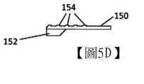
圖4示出圖3A和3B的連接器110之一部份分解圖。在一實施例中,如更詳細地示於圖5A~5D中,該鍵130可包含一主體部150,其可包含一槽或孔151在該鍵之一第一端,及一導軌152在該鍵之一第二端,該導軌152可被構製成能套入該等槽132a、132b的任一者中來導引該鍵130縱向移入一槽內,並在插入該槽內後能阻止該鍵的側至側(側向)移動。該等導軌152和槽132a、132b亦可相對於彼此被構製成能阻止該鍵以一橫交於該縱軸的方向移出該槽外。在一實施例中,該等槽132a、132b的寬度可在一由該殼體之外表面朝內表面的方向加寬。該導軌152可被對應地構製成,如圖5C中所示,具有一較窄的寬度鄰近該主體150,並在一延伸離開該基部的方向加寬。以此一構形該鍵130當插入一槽132a或132b中時,乃可實質上被阻止由該殼體126向上抬離,同時亦會被阻止在該殼體上側向地移動。FIG. 4 shows a partial exploded view of the
為相對於該殼體126縱向地卡抵該鍵130,該殼體可包含一凸體160,該鍵主體150可越過其上而被插入來將該凸體銜抵於該孔151內。該凸體160可為至少在該插入方向朝外地推拔離開該殼體,以便於該鍵主體150向上移升並越過該凸體。為方便一鍵130的移除,當與該凸體160卡抵 時,該鍵主體可包含至少一抓持脊緣154,或者多數個脊緣(如所示)沿該主體150佈設。該等脊緣可被構製成能被例如以一指甲卡抵,而來由該殼體126拉出該鍵。In order to press the key 130 longitudinally with respect to the
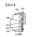
該連接器殼體110的其它細節可以在圖6A~6E所示的各圖中被看出。圖6A和6B示出裝有該鍵130的連接器110之代表性的正面和側面視圖。圖6C為沿圖6A中的C-C線之一截面圖,而圖6D為沿圖6B中的D-D線之一截面圖。如於前針對圖1所述,該外殼體128可被圍繞該內殼體126可滑動地配設,且一彈簧170可被提供來向前地,或朝該內殼體的第一端或插入端來偏壓該外殼體,如圖6D中所示。凸耳129等,如詳示於圖6E中者,可被構製成能限制該外殼體128沿該內殼體126的向前移動。Other details of the
該外殼體128可在該內殼上被向後地移動一距離d1。該外殼體於該距離d1上的移動會提供至該等槽隙134的通路,以供配接器凸耳(譬如圖1中的凸耳24a、24b)卡抵於該等槽隙中,而使該連接器110銜接於一配接器內。同樣地,該外殼體128亦可被移位該距離d1來釋放該等配接器凸耳,用以由該配接器移除該連接器110。圖6E示出該鍵主體150和孔151與該內殼體126的凸體160之間的互接之一詳圖。如圖6E中所示,該主體150的第二端可套塞於該內殼體126與外殼體128之間。如此,在一實施例中,該外殼體128可被移位該距離d1來提供餘隙,以使該鍵能被插入該內殼體126上。當該外殼體128被向前偏壓如所示時,該鍵主體150可被阻止由該凸體160釋脫。要移除該鍵130時,該外殼體128 可被向後滑移該距離d1來提供餘隙以供該鍵主體150升高而由該凸體160周圍朝外離開。The
一可移除鍵230之一另擇實施例係示於圖7中。在圖7的實施例中,該導軌252可為實質上類似於如前所述的導軌152。或者,該導軌152可具有一另擇的構形。該抓持表面可包含至少一凹溝254,其功能可實質上如同前述的脊緣154,即是,用以提供一表面其可被輕易地卡抵來由該內殼體226滑移該鍵230。在一實施例中,該鍵230可在該第一端231具有一實心鍵體250,或另擇地,如所示,可包含一伸長的槽孔251,其可提供如後更詳述的各種功能。An alternative embodiment of a
在如圖7和8中所示之一實施例中,該用以可釋脫地扣持該鍵230與該內殼體226的構造可包含側向凸耳256a、256b在該鍵主體250的第一或插入端231。該等側向凸耳256a、256b可被構製成能界定對應的側向凹槽258a、258b。該頂或底表面226,除了具有槽等可供容納該導軌252(未示出,但實質上類似於圖4中的槽132a、132b)外,可包含凸體272a、272b等構製成能跨夾該鍵主體250,其中該等凸體之間的寬度可為實質上如同該鍵主體在該等側向凹槽258a、258b之間的寬度。In an embodiment shown in FIGS. 7 and 8, the structure for releasably holding the key 230 and the
該鍵230可藉該第一鍵端231插入該等凸體272a、272b之間而與該內殼體226卡抵。因在該第一端231包含一槽孔251於該等側向凸耳256a、256b之間,故該等凸耳可更容易地被朝內偏移而來容許該等凸耳通過該等凸體272a、272b之間。或者,若一槽孔251未被包含,則某些聚合性材 料可被構製成該鍵,其可為充分地彈性以容許該等凸耳256a、256b向內壓縮而來允許該等凸耳移動通過該等凸體272a、272b。一旦通過該等凸體272a、272b之後,該等凸耳256a、256b可再朝外推壓並扣持該鍵230來與該內殼體226卡抵,至少在該鍵插入的縱向。The key 230 can be inserted between the protruding
該主體250在該第一端231的厚度可實質上如同該內殼體226與一外殼體228(圖9A~9C)之間所界定的空隙,因此當該外殼體在定位時該鍵230不能被升高離開該內殼體,而可確保該鍵230的移除必須藉該鍵由該等凸體272a、272b之間的縱向移位才能達成。The thickness of the
圖9A~9C示出一外殼體228之一另擇實施例。配合該鍵230具有一槽孔251,該外殼體的內側可包含一導塊275,其係構製成當該外殼體沿該內殼體226縱向地移動時能套入該伸長槽孔內而在該槽孔內移動。在一實施例中,該導塊275亦可提供一附加的擋止物用以阻止該鍵230由該內殼體226與外殼體228之間縱向地退出。當該外殼體228係在其如所示的向前偏壓位置時,該鍵主體250的厚度可為實質上如同該內和外殼體之間的距離。如此,當該鍵230在圖中縱向朝下的最初移動時,該槽孔251將會沿該導塊275移動,直到該第一端231的內表面231a接觸該導塊為止,故而會阻止該鍵進一步朝外移動。9A-9C show an alternative embodiment of an
為使該鍵230的第一端231可進入該內殼體226與外殼體228之間的空隙中,該內殼體可包含一凹部276其具有一深度凹入該殼體中而足以允許該第一端通過該導塊 275與該內殼體之間。在一如圖9B和9C所示的實施例中,該凹部276的最深部份可沿該內殼體226位在一位置處,其對應於一位置,即當該外殼體228朝向該內殼體的後端移位時,該導塊275可能會在之處。如此,當該外殼體228被偏壓向前進入其正常使用位置時,該鍵230將不會通過該導塊275與該內殼體226之間。該鍵230僅會在當該外殼體228先被朝向該內殼體226的後端移位時才可通過。In order to allow the
在所揭的各種實施例中,該等鍵和殼體組件,可例如由剛性聚合物或金屬來形成。一般而言,任何種類的實質上剛性材料皆可被使用。該材料應具有一剛性足以保持該鍵與該殼體之間的必要卡抵,俾使該鍵保留在定位,除非當有一力被施加來移除該鍵時。In the various embodiments disclosed, the keys and housing components may be formed of rigid polymer or metal, for example. Generally speaking, any kind of substantially rigid material can be used. The material should have a rigid enough to maintain the necessary snap between the key and the housing, so that the key remains in place, unless a force is applied to remove the key.
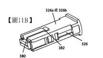
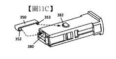
一鍵330之另一實施例係示於圖10A和10B中。該鍵330可例如為一成形的金屬帶或剛性聚合物。該鍵330可包含一縱長主體350具有一第一端350a和一第二端350b。一連接器310配合一鍵330係示於圖11A~11C中。在該內殼體326的前端處,各該側壁326a和326b可包含一凹槽或凹口380,係被構製成能將該鍵330的第二端容納其中。該第二端350b可為鈎狀或U形以提供一彎折的凸緣352構製成能繞該內殼體326的前端套合。此一鈎和凹口的構造可阻止該鍵330在該等側壁326a、326b上側向移動,並可阻止橫向地移離該殼體,或由該第二端升高脫離該殼體。Another embodiment of a key 330 is shown in FIGS. 10A and 10B. The key 330 can be, for example, a shaped metal tape or rigid polymer. The key 330 may include a
該鍵330的第一端350a可包含一凸耳353,其會由該主體350實質上正交地延伸。如圖11B和11C中所示,該內 殼體可具有一凹部、槽或孔382,構製成可將該凸耳353容納其中。當凸耳353卡抵於該槽382內時,該鍵330的縱向移動可被抑止。如圖11A中所示,外殼體328可阻止該鍵330的第一端350a升高離開該內殼體326,因此當該外殼體被偏壓進入其向前位置時,該鍵330會實質上定位鎖住於該殼體上。The
外殼體328可被向後移位以供安裝及移除該鍵330。要安裝時,被外殼體328可對抗彈簧(未示出,但於前有述)的偏壓而被向後移位。該凸緣352可被與該凹口380對準,且該鍵可被縱向地滑入定位而使該凹口中的凸緣會對準該凸耳353與該槽382。凸耳353可被推入該槽382中,且該外殼體328可被釋放而向前移動來覆蓋該鍵330的第一端350a並將該鍵固持定位。此程序可以倒反來供移除該鍵330。外殼體328可被向後移位,凸耳353可被升高脫出該槽382外,且該鍵可被縱向地滑離該內殼體326。The
在一另擇實施例中,如圖12A、12B和13A~13C中所示,一鍵430可被構製成能可釋離地與該外殼體428連接。該鍵430可包含一縱長主體部450及一導軌452在該第二端450b。該導軌452可被構製成能以一如先前針對圖6A~6E所述的方式來卡抵於該內殼體426之一槽432a或432b中。在一實施例中,取代在該插入端之一孔,該主體450可包含一凸體455其會由該主體伸離。為與該凸體455卡抵,如詳細示於圖13C中,該外殼體428可包含一插孔490,當該外殼體定位圍繞該內殼體426時,該凸體可伸入其中。In an alternative embodiment, as shown in FIGS. 12A, 12B, and 13A-13C, a key 430 may be configured to be releasably connected to the
類似於先前的實施例,該鍵430的第二端450b可藉該導軌452的構形於側向和橫向被扣持在該等槽432a、432b內。當插入或移除該鍵430時,該第二端450b可實質上僅在該縱向是可移動的。當插入時,該鍵430的第一端450a可被一對由該內殼體伸出並在其間界定一空隙實質上係如同該主體部450之寬度的凸體492固持於定位而不能側向移動。該外殼體428可含可下壓的凸耳488等,其當被壓下時,會向下地壓著於該第一端450a上來釋脫該凸體455與該插孔490的卡抵。Similar to the previous embodiment, the
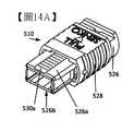
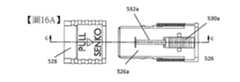
在一另擇實施例中,如圖14A、14B、15A、15B、16A、16B和16C中所示,取代一單鍵其可配合該連接器之頂或底側壁的各面來被擇變地置設,一連接器510可被構製成使各側壁526a、526b皆包含一對應的可移位鍵530a、530b。類似於先前的實施例,該連接器510可包含一內殼體526與一可縱向移位的外殼體528圍繞該內殼體配設。各側壁526a、526b可包含一縱向槽532a、532b由該內殼體526的後端向前延伸,且如後所述,該等鍵係可沿該等槽的長度移位。視所需的極性而定,該等鍵530a或530b之一者可被朝前地置設在該等槽532a或532b中,而另一者係置於該槽道外,或隱藏在該外殼體底下。在一實施例中,該等槽532a、532b的寬度在一由該殼體之外表面朝內表面的方向可被加寬。In an alternative embodiment, as shown in FIGS. 14A, 14B, 15A, 15B, 16A, 16B, and 16C, instead of a single key, it can be fitted to each surface of the top or bottom side wall of the connector to be selectively changed. Alternatively, a
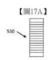
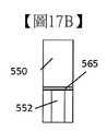
如圖17A~17E中所示,各鍵530可包含一鍵主體550及一突出的導軌552,類似於先前參照圖5A~5D所述的鍵130。凸軌552鄰接該主體550處可具有一較窄的寬度,並 可在一由該主體伸離的方向加寬,或具有一設成遠離該主體的底部其有一寬度係大於鄰接該主體處的寬度。槽532a、532b可包含一放大的入口533a、533b,其具有一寬度足以容許該導軌552通過其中。圖16B示出該鍵530a設在該槽532a上方且該導軌552在該入口533a上方,而該鍵530b設在該槽532b中。當插入穿過該等入口後,該等鍵530a、530b可被沿該等槽532a、532b縱向地移位,且一旦由該等入口向前移動後,將不能在一橫交於該等槽之縱向的方向升高脫出該等槽外,因為該導軌的構形具有該較大的寬度設在離開該主體處。As shown in FIGS. 17A to 17E, each key 530 may include a
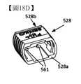
圖18A~18D示出該內殼體526和外殼體528。在實施例中,該內殼體526可包含擋止物529等,構製成能限制該外殼體528在該等彈簧570的偏壓下之向前移動。該外殼體可具有一前端528a用以當設在該內殼體上時可被設成朝向該內殼體526的前端,及一後端528b設成相反於該前端。該外殼體528可包含內擋止物561等,其可被設成鄰近該後端528b,並構製成可與該內殼體526的擋止物529卡抵。該等擋止物529之一朝前表面可為朝該內殼體的後方向上呈斜角地傾斜,因此當該外殼體由該內殼體的前端滑入該內殼體上時,該外殼體能被壓迫越過該等擋止物。18A to 18D show the
圖19A~19E示出該等可移位鍵530a、530b相對於該等可移位外殼體528和內殼體526的操作。圖19A示出一連接器構製成具有一第一極性,而鍵530a在一向前的“有效”位置,且鍵530b在一隱藏的“無效”位置。要改變該極性時, 該外殼體528可在該內殼體526b上被向後移位,如圖19B中所示。在移位該外殼體528之後,鍵530b將會部份地曝露。鍵530a可被向後滑出其“有效”位置而進入其“無效”位置,且如圖19C中所示,該等二鍵皆可在它們的“無效”位置。鍵530b可被向前滑出其“無效”的隱藏位置而進入其“有效”位置,如圖19D中所示,且該外殼體528可被釋放而回到其向前位置,如圖19E中所示。19A-19E show the operation of the
雖上述順序示出切換該極性之一模式,但該等移動順序可以改變。例如,鍵530b可在向後移動鍵530a之前先被向前移動。為使該等鍵530a、530b保持在該向前或向後位置,該外殼體及/或鍵等可包含一擋止/扣持構形。在一實施例中如圖20A~20C所示(亦參見圖18A),該等壁526a、526b的外表面可包含一脊緣563a置設對應於一鍵的向前位置,及一脊緣563b置設對應於一鍵之一向後位置。該等鍵530a、530b如在圖17A~17E中所示,可包含一對應的槽565(圖17B、17C、17E)用以與該等脊緣563a或563b之一者銜抵,乃視該鍵的位置而定。因此各鍵530a、530b可被縱向地移動越過該等脊緣,且當該等槽與一脊緣卡抵時,該等鍵與該殼體之間的摩擦銜抵將會增加,而一操作該連接器的人當銜抵發生時將能感覺到。一旦銜抵後,則將會需要一增加的力量才能由它們的銜抵位置來移動該等鍵。另擇的銜抵細構之構形亦可被提供。作為一例,如前參照圖7和8所述,側向凸體和凹槽,類似於凸耳256a和凹槽258a等可被提供於一鍵530a、530b的側面上,且該殼體表面可包含一 凸體譬如凸體272a等,因此一如前所述的類似卡抵乃可被提供用於該內殼體上之鍵的定位。或者,該等特徵細構亦可倒反,其中該殼體可包含槽,而該等鍵可包含對應的脊緣等。Although the above sequence shows switching the mode of one of the polarities, the sequence of these movements can be changed. For example, the key 530b may be moved forward before the key 530a is moved backward. In order to keep the
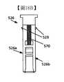
在該可移位鍵之一變化例中,一鍵630可被構製成如圖21A~21C中所示。在一實施例中,該鍵630可具有一較長的主體650,因此該主體之長度的一半以上,例如該鍵主體的約3/5至約2/3,將會被該外殼體628覆蓋,如圖23A中所示,當該外殼體係在其休止或向前位置時。以此種構形,該導軌652可被構製成一“鰭片狀”凸體由該主體650伸出。如圖22中所示,該內殼體626上之一縱長槽632可被構製成能將該導軌652容納其中。類似先前所述的實施例,該內殼體626之各該頂和底表面可為實質上相同的。In a variation of the shiftable key, a key 630 can be constructed as shown in FIGS. 21A to 21C. In one embodiment, the key 630 may have a
因為至少有例如該鍵630之長度的約3/5可被設在該內殼體與該外殼體之間,故當該外殼體在其向前位置如所示時,例如因圖23A中的鍵630a在其向前或“有效”位置,該外殼體將會實質上阻止該鍵側向移動離開該內殼體626。當該外殼體628在此位置時,該鍵630b將會實質上被隱藏在其向後或“無效”位置。因此該導軌652在其離開該主體的一端可不須要任何如先前針對導軌552所述的加寬。Because at least, for example, about 3/5 of the length of the key 630 can be provided between the inner housing and the outer housing, when the outer housing is in its forward position as shown, for example, as shown in FIG. 23A With the key 630a in its forward or "active" position, the outer shell will substantially prevent the key from moving laterally away from the
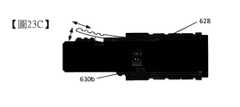
如在先前的實施例中,該外殼體628可被向後移位至一位置如圖23B中所示。在此實施例中,例如,該“有效”鍵的只有1/3至2/5才可被該外殼體覆蓋。當該外殼體628於此位置時,該“無效”的鍵630b可被曝露,以供若需要時 可銜抵該鍵來向前拖拉該鍵。該“有效”鍵630a可被向後推入其“無效”位置,且藉改變該二鍵的位置,該連接器的極性乃可被改變。或者,如圖23C中所示,當該外殼體628係在其向後位置時,該鍵630a及/或630b可被由該連接器移除或插入該連接器上的位置,因該鍵的材料之一可撓性可提供足夠的游隙使該鰭片狀導軌652能被升高脫出它的對應槽632外,而使一鍵可被拉出或插入該連接器中。As in the previous embodiment, the
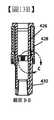
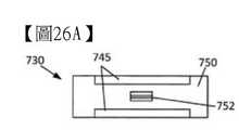
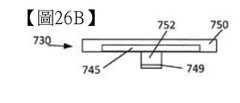
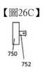
在又一實施例中,如圖24~26C所示,一連接器710可包含一扣入鍵730。該內殼體726之各該頂或底壁726a或726b可為實質上相同的,並包含一槽732用以容納該鍵730之一扣入凸體。該鍵730可包含一鍵主體部750,及一凸出的卡抵構件752其係構製成能套入該槽732內並扣持該鍵730來與該內殼體726銜接。該卡抵構件752可被構製成一“扣入”式連接物,其中該卡抵構件可壓縮來塞入穿過該槽732,然後擴張以將構件扣持於該槽內。一般而言,任何類型的“扣入”式構形皆可使用。In another embodiment, as shown in FIGS. 24 to 26C, a
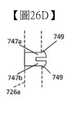
在一如所示的實施例中,該卡抵構件752可包含第一和第二腳部747a和747b被一槽隙分開,其容許該等腳部能被彈性地朝向彼此移位以便進入並穿過該槽732。一旦穿過該槽732則該等腳部747a、747b可回復至它們的自然位置。該等腳部747a、747b的一或二者可包含一扣爪749由該腳部向外突出,而使該卡抵構件具有一寬度係大於該槽隙732之一寬度。如圖26D中所示,一內殼體壁被以輪廓線示出,當該等腳部747a、747b穿過該內殼體壁中的槽隙732並 回復至其自然位置時,該等扣爪能卡抵該殼體壁的內側表面而得提供一扣持力阻止該鍵730由該內殼體726移除。In an embodiment as shown, the abutting
該鍵主體750可包含凹陷的凹口745等沿著其縱向側邊延伸,以方便由該槽隙732移除該鍵730。該等凹口745可被構製成能提供空間以供一工具插入,譬如一小螺絲起子,或甚至一指甲,在該主體750底下施加一揚升力並向上抬高該鍵730離開該內殼體726。為防止一鍵730在該內殼體726上旋轉,該卡抵構件752和槽隙732可具有一長度尺寸(於該鍵或殼體之一縱向)其係為一橫交於該長度尺寸之寬度尺寸的至少兩倍長。The
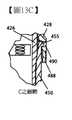
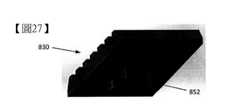
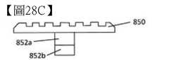
有一不同於該“扣入”構形的另擇例,如圖27和28A~28C中所示,一鍵830可被構製成具有一扭轉鎖定連接物852。該鍵830可包含一連接物852,其會延伸離開該鍵之一主體部850的底表面。該連接物852可包含一軸部852a由該主體部850伸出,及一臂部852b會由該軸部伸離。在一實施例中,該臂部852b可僅於該軸的一側由該軸部852a伸出,如所示。或者,該臂部852b和軸部852a可被構製或具有一“T”構形,且該臂部可於二相反方向橫向地延伸離開該軸部(未示出)。該等頂和底壁826a和826b可包含一對應的通道831具有一尺寸和形狀構製成可供該臂部826b通過其中。該軸部852a可具有一長度由該主體部850伸出,而使該長度至少在該通道831附近可為實質上如同該頂和底壁826a和826b之一壁部的厚度。因此該臂部852b在被插入穿過該通道831並嗣繞該軸852a旋轉之後,可與該頂或底壁826a和826b之 一內表面卡抵銜接,如圖29中所示。As an alternative to the "snap-in" configuration, as shown in FIGS. 27 and 28A-28C, a key 830 can be configured to have a
如圖29中所示,該鍵830可被附接於該頂或底壁826a、826b之任一者,乃藉如虛線的鍵輪廓所示來對準該鍵(該鍵的縱軸橫交於該連接物的縱軸),再將該臂部826b插入穿過該開孔831並旋轉該鍵約90°至該“鎖入”鍵位置,如實線的鍵輪廓所示(該鍵的縱軸與該連接物的縱軸對準)。一旦旋轉後,該臂部826b如虛線輪廓所示將不會再與該通道831對準,且將會與該頂或底表面826a、826b之一內表面卡抵,而得阻止該鍵830的揚升或移除離開該頂或底壁。As shown in Figure 29, the key 830 can be attached to any of the top or
要改變該連接器的極性時,該鍵830可被轉回至其橫向位置(虛線),並由該頂或底壁826a、826b抬高,再重裝於相反的表面上。為限制該鍵830的旋轉移動,該等壁的內面可包含一擋止構件833,如圖30A中所示,其當該鍵旋轉約90°時,會被該臂部826b卡抵而阻止進一步旋轉。該擋止構件可由該壁之一加厚部,或一由該壁突出物來提供,或者該臂可在一由內部朝向外部伸入該壁中的凹部859內旋轉,該凹部可具有一1/4或半圓的形狀,因此該凹部的側邊可提供旋轉擋止物。To change the polarity of the connector, the key 830 can be turned back to its lateral position (dotted line), raised by the top or
可附加於或作為該擋止物833之一擇代例,以一類似於圖18A和20A之實施例的方式,一脊緣863可被提供在該頂和底壁826a、826b的外表面上,且該鍵主體850的底表面可包含一對應的槽855用以當該鍵830轉入其鎖定位置時能與該脊緣卡抵。該脊緣/槽構造亦可被構製成當一鍵係為“鎖入”時,能提供阻力以使一鍵在該等表面上的意外旋 轉最少化。若一擋止物833未被提供,該脊緣/槽構造亦會提供一使用者一顯著的卡抵來表示該鍵在該殼體上有一妥確的對準。Can be added to or as an alternative to the
在一另擇實施例中(未示出),該軸852a可被以至少一圓周螺紋,且該開孔831可包含一配接螺紋,而該軸在該開孔內旋轉可使該鍵以一如一螺帽與螺栓銜接所示的方式來螺合於該壁中或螺退於壁外。In an alternative embodiment (not shown), the
針對以上任一實施例所述的各種部件、組件或構造等亦可被配用於所提供的任何其它實施例。The various components, components, or configurations described for any of the above embodiments can also be used in any of the other embodiments provided.
本揭露並不受限於所揭的特定系統、裝置和方法,因這些可以改變。使用於本說明中的專業術語係僅為描述該等特定態様或實施例之目的,而非意要限制其範圍。The present disclosure is not limited to the specific systems, devices, and methods disclosed, as these can be changed. The terminology used in this description is only for the purpose of describing the specific aspects or embodiments, and is not intended to limit the scope.
在以上詳細說明中,係參照所附圖式,其形成說明的一部份。在該等圖式中,類似的符號典型會標示類似的組件,除非內文有其它不同的表示。描述於該詳細說明、圖式和申請專利範圍中的舉例實施例等並無意作為限制。其它的實施例亦可被使用,且其它的變化可能被製成,而不偏離於所呈現的主題內容之精神或範圍。應可輕易地瞭解在此被概括地描述並示於該等圖中之本揭露的態様等,係能以許多種不同的構態來被安排、替代、組合、分開和設計,它們全部皆會在此被明確地預期。In the above detailed description, reference is made to the accompanying drawings, which form a part of the description. In the drawings, similar symbols typically indicate similar components, unless the content has other different representations. The example embodiments described in the detailed description, drawings, and the scope of the patent application are not intended to be limiting. Other embodiments may also be used, and other changes may be made without departing from the spirit or scope of the presented subject matter. It should be easy to understand that the state of the disclosure described here and shown in these figures can be arranged, substituted, combined, separated and designed in many different configurations, all of which will be It is clearly expected here.
本揭露並不受限於本申請案中所述的特定實施例之形式,它們係意要作為各種不同態様的例示。如精習於該技術者顯然可知,許多修正和變化能被製成而不偏離 於其精神和範圍。除了於此列舉者外,在本揭露之範圍內功能上等同的方法和裝置,將可為精習於該技術者由先前說明中輕易得知。此等修正和變化係意圖落在所附請求項的範圍內。本揭露係要僅由所附請求項的內容,以及該等請求項所指稱之等效物的全部範圍來限定。應請瞭解本揭露並不受限於特定的方法、反應例、化合物、組成物或生物系統,其當然是可以改變。亦請瞭解於此所用的術語係僅為描述特定實施例之目的,而非意要作為限制。The present disclosure is not limited to the form of the specific embodiments described in this application, and they are intended to serve as illustrations of various different aspects. Those who are acquainted with this technology will obviously know that many modifications and changes can be made without departing from its spirit and scope. In addition to those listed here, methods and devices that are functionally equivalent within the scope of the present disclosure will be easily understood by those skilled in the technology from the previous description. These amendments and changes are intended to fall within the scope of the attached claims. This disclosure is to be limited only by the content of the attached claims and the full scope of the equivalents referred to in these claims. Please understand that the present disclosure is not limited to specific methods, reaction examples, compounds, compositions or biological systems, which can of course be changed. Please also understand that the terminology used herein is only for the purpose of describing specific embodiments and is not intended to be a limitation.
若被用於本文件中,單數形式的“一”、“一個”、和“該”等包含多數之意,除非該內文清楚地表示其它不同的意思。除非另有不同的界定,於此所用的全部技術和科學用語具有如同一般精習於該技術者共同瞭解的意義。本揭露中並無任何會被視為承認本揭露中所述的實施例未被指明由於先前的發明而更早於本揭露。若被用於本文件中,該“包含”乙詞意指“包括,但不限於”。If used in this document, the singular forms of "a", "an", and "the" include the majority meaning, unless the content clearly expresses other different meanings. Unless otherwise defined differently, all technical and scientific terms used here have the same meanings commonly understood by those who are familiar with the technology. Nothing in this disclosure will be regarded as an acknowledgement that the embodiments described in this disclosure are not specified earlier than this disclosure due to previous inventions. If used in this document, the word "including" means "including, but not limited to."
雖各種不同的組成物、方法和裝置等係以“包含”各種組件或步驟的方式來被描述(視為意指“包括,但不限於”),但該等組成物、方法和裝置亦可“主要由”或“由”該各種組件和步驟等“所組成”,且此專業術語應被視為實質上界定出封閉數目的組群。Although various components, methods, and devices are described in terms of "comprising" various components or steps (considered as meaning "including, but not limited to"), these components, methods, and devices may also "Mainly composed of" or "consisting of" the various components and steps, etc., and this technical term should be regarded as essentially defining a closed number of groups.
針對於此所用之實質上任何複數及/或單數的用詞,精習於該技術者將能依對該內容及/或申請案的瞭解,而由該複數轉換成單數及/或由該單數轉換成複數。該不同的單數/複數互換為了清楚之故可被明白地陳述於此。Regarding essentially any plural and/or singular terms used here, those skilled in the technology will be able to convert the plural into the singular and/or from the singular based on the understanding of the content and/or application Convert to plural. The different singular/plural interchange can be stated here clearly for clarity.
專業人士將會瞭解,一般而言,於此之用語,且尤其是在所附請求項中者(例如該等請求項的主體)通常係要作為“開放”用語(例如該“包含”乙詞應被釋為“包括但不限於”,該“具有”乙詞應被釋為“至少具有”,該“含有”乙詞應被釋為“含有但不限於”等)。又專業人士更會瞭解若一被引介的請求指述物之一特定數目係被欲求,則此一意圖會被明白地陳述於該請求項中,而若無此陳述就沒有該意圖會呈現。例如,作為對瞭解之一幫助,以下的請求項可包含使用引介片語“至少一個”及“一或更多個”來引介請求指述物。但是,使用該等片語不應被視為暗示一請求指述物被以不限定用語“一”或“一個”引介,會將包含此被引介的請求指述物之任何特定請求項限制於只包含一個該指述物的實施例,甚至當同一請求項包含該等“一或更多個”或“至少一個”引介片語,和不限定用語譬如“一”或“一個”時(例如“一”及/或“一個”應被釋為意指“至少一個”或“一或更多個”);對被用來引介請求指述物的限定用語之使用亦同此理。此外,即使若一被引介的請求指述物之一特定數目係被明白地陳述,精習於該技術者將會瞭解該陳述應被釋為意指至少有該所陳述的數目(例如“二指述物”的原本陳述,若沒有其它修正,則意指至少二個指述物,或二或更多個指述物)。又,在一類比於“A、B和C等之至少一者”的慣例被使用的情況下,通常此一結構係寓意於一精習該技術者會瞭解該慣例(例如,“一系統具有A、B和C之至少一者”應會包含但不限於如下的系統:只具有A,只具有B,只具有C,有A 和B,有A和C,有B和C,及/或A和B和C一起等)。在若一類比於“A、B或C等之至少一者”的慣例被使用的情況下,通常此一結構係寓意於一精習該技術者會瞭解該慣例(例如,“一系統具有A、B或C的至少一者”將會包含但不限於如下的系統:只具有A,只具有B,只具有C,有A和B,有A和C,有B和C,及/或A和B和C一起等)。專業人士亦會瞭解,事實上任何呈現二或更多個選項的選言用字及/或片語,不論是在說明、請求項或圖式中,應被瞭解為預期包含該等選項之一者,該等選項之任一者,或該二選項的可能性。例如,該片語“A或B”會被瞭解有包含“A”或“B”或“A和B”的可能性。Professionals will understand that, in general, the terms used here, and especially those in the attached claims (such as the subject of such claims) are usually used as “open” terms (such as the “contains” term). Should be interpreted as "including but not limited to", the word "having" shall be interpreted as "at least having", and the word "containing" shall be interpreted as "including but not limited to" etc.). Professionals will also understand that if a certain number of referents introduced in the request is desired, then this intention will be clearly stated in the request, and if there is no such statement, no such intention will be presented. For example, as an aid to understanding, the following request items may include using the introductory phrases "at least one" and "one or more" to introduce the requested reference. However, the use of these phrases should not be regarded as implying that a request reference is introduced with the unrestricted terms "one" or "one", and will restrict any specific request containing the referenced request to Only one embodiment of the descriptive material is included, even when the same claim includes such "one or more" or "at least one" introductory phrases, and unrestricted terms such as "one" or "one" (for example "A" and/or "an" shall be interpreted as meaning "at least one" or "one or more"); the same applies to the use of the limited terms used to introduce the requested reference. In addition, even if a specific number of a referenced request is stated clearly, those skilled in the technology will understand that the statement should be interpreted as meaning that there is at least the stated number (for example, "two The original statement of "referential things" means at least two referents, or two or more referents if there are no other amendments). Moreover, when a convention analogous to "at least one of A, B, and C" is used, usually this structure implies that a person who is intensively familiar with the technology will understand the convention (for example, "a system has At least one of "A, B, and C" shall include but is not limited to the following systems: only A, only B, only C, A and B, A and C, B and C, and/or A and B and C wait together). If a convention analogous to "at least one of A, B, C, etc." is used, usually this structure implies that a person who is well versed in the technology will understand the convention (for example, "a system has A "At least one of, B, or C" will include but is not limited to the following systems: only A, only B, only C, A and B, A and C, B and C, and/or A Wait with B and C). Professionals will also understand that, in fact, any choice words and/or phrases that present two or more options, whether in descriptions, requests, or diagrams, should be understood as expected to include one of these options , Any of these options, or the possibility of the two options. For example, the phrase "A or B" will be understood to contain the possibility of "A" or "B" or "A and B".
此外,若該揭露的特徵或態樣係以馬庫西(Markush)組群的方式來被描述,則專業人士將會瞭解該揭露亦因此係被以該馬庫西組群之任何個別數目或數目的次組群之形式來描述。In addition, if the feature or aspect of the disclosure is described in terms of the Markush group, the professionals will understand that the disclosure is therefore based on any individual number or pattern of the Markush group. The number is described in the form of subgroups.
如精習於該技術者所瞭解,為了任何及所有的目的,譬如以提供一書寫說明之觀點而言,於此所揭的全部範圍亦包含任何和所有可能的次範圍及其次範圍的組合。任何列示的範圍皆能因充分地描述而被容易地瞭解,並使該同一範圍能被分解成至少相同的兩半、1/3、1/4、1/5、1/10等。如一非限制例,每個於此所述的範圍可被輕易地分成一較下的1/3,中間的1/3和較上的1/3等。如精習於該技術者亦會瞭解者,譬如“最多”、“至少”和類似的所有用語,包括所述數目和指述範圍者,皆可嗣後被分成次範圍 如前所述。最後,如一精習於該技術者所瞭解,一範圍包含每一個別的數目。故,例如,一具有1~3個胞元的組群係指具有1、2或3個胞元的組群。同樣地,一具有1~5個胞元的組群係指具有1、2、3、4或5個胞元的組群,依此類推。As those skilled in the technology understand, for any and all purposes, such as the point of view of providing a written description, the full range disclosed here also includes any and all possible sub-ranges and combinations of sub-ranges. Any listed range can be easily understood with sufficient description, and the same range can be decomposed into at least the same two halves, 1/3, 1/4, 1/5, 1/10, etc. As a non-limiting example, each range described here can be easily divided into a lower 1/3, a middle 1/3, an upper 1/3, etc. Those who are well versed in the technology will also understand, such as "at most", "at least" and all similar terms, including the number and the scope of reference, can then be divided into sub-ranges as described above. Finally, as a person skilled in the technology understands, a range encompasses each individual number. So, for example, a group with 1 to 3 cells refers to a group with 1, 2, or 3 cells. Similarly, a group with 1 to 5 cells refers to a group with 1, 2, 3, 4, or 5 cells, and so on.
上揭之各種及其它的特徵和功能,或其另擇例等,可被結合於許多其它不同的系統或用途中。各種目前未預知或未預期的擇代、修正、變化或其中的改良,可能日後被精習於該技術者作成,其每一者亦意圖要被所揭的實施例所包含。The various and other features and functions disclosed above, or alternative examples thereof, can be combined in many other different systems or uses. Various currently unforeseen or unexpected alternatives, modifications, changes, or improvements therein may be made by those skilled in the technology in the future, and each of them is also intended to be included in the disclosed embodiments.
10、10a、10b、110、310、510、710:連接器12:配接器14:套環15a:光纖纜線15b:纜線引出罩16、231、350a:第一端18、22:孔口20、350b、450b:第二端24a、24b、129、353、488:凸耳26、126、226、326、426、526、626、726:內殼體28、128、228、328、428、528、628、728:外殼體30、130、230、330、430、530、530a、530b、630、730、830:鍵32:鍵槽34a、34b、134:槽隙126a、326a、526a、726a、826a:頂側壁126b、326b、526b、726b、826b:底側壁132a、132b、432a、432b、532a、532b、565、632、732、855:槽140:縱軸150、250、350、450、550、650、750、850:主體部151、251、382:槽孔152、252、452、552、652:導軌154、563a、563b、863:脊緣160、272a、272b、455、492:凸體170、570:彈簧231a:內表面254:凹溝256a、256b:側向凸耳258a、258b:側向凹槽275:導塊276、859:凹部528a:前端352:凸緣380:凹槽490:插孔561、529:擋止物528b:後端533a、533b:入口745:凹口747a、747b:腳部749:扣爪752:卡抵構件831:通道833:擋止構件852:扭鎖連接物852a:軸部852b:臂部d1:移動距離10, 10a, 10b, 110, 310, 510, 710: connector12: Adapter14: collar15a: Optical fiber cable15b: Cable exit cover16, 231, 350a: first end18, 22: Orifice20, 350b, 450b: second end24a, 24b, 129, 353, 488: lugs26, 126, 226, 326, 426, 526, 626, 726: inner shell28, 128, 228, 328, 428, 528, 628, 728: outer shell30, 130, 230, 330, 430, 530, 530a, 530b, 630, 730, 830: key32: keyway34a, 34b, 134: slot gap126a, 326a, 526a, 726a, 826a: top side wall126b, 326b, 526b, 726b, 826b: bottom side wall132a, 132b, 432a, 432b, 532a, 532b, 565, 632, 732, 855: Slot140: vertical axis150, 250, 350, 450, 550, 650, 750, 850: main body151, 251, 382: Slots152, 252, 452, 552, 652: rail154, 563a, 563b, 863: Ridge edge160, 272a, 272b, 455, 492: convex body170, 570: Spring231a: inner surface254: Groove256a, 256b: lateral lugs258a, 258b: lateral groove275: guide block276, 859: recess528a: front end352: Flange380: Groove490: Jack561, 529: Stop528b: backend533a, 533b: entrance745: Notch747a, 747b: feet749: Claw752: Snapping member831: Channel833: stop member852: Twist Lock Connector852a: Shaft852b: Armd1: moving distance
圖1示出一依據一實施例的MPO連接器之立體圖。圖2A和2B示出依據一實施例的MPO連接器之配接/極性構態。圖3A和3B為一依據一實施例的光纖連接器殼體之代表性頂視和底視立體圖,具有一可卸除的鍵用以改變該連接器的極性。圖4為一依據圖3A和3B的實施例之部份分解的光纖連接器殼體之立體圖。圖5A~5D為依據圖3A和3B的實施例之一鍵的底、頂、端和側視圖。圖6A~6E為依據圖3A和3B的實施例之光纖連接器殼體的正面、側面、截面和詳細視圖。圖7為一依據一實施例之另擇鍵的立體圖。圖8示出圖7的鍵依據一實施例置設在一連接器殼體上。圖9A~9C為圖8的實施例之一連接器的正面、截面和詳細視圖。圖10A和10B為依據實施例之一另擇鍵的不同立體圖。圖11A~11C為一依據一實施例的連接器與圖10A和10B之鍵的各種視圖。圖12A和12B為一依據一實施例的另擇鍵之不同立體圖。圖13A~13C為一依據一實施例的連接器與圖12A和12B的鍵之各種視圖。圖14A和14B為一依據一實施例之具有可動鍵的連接器之立體圖。圖15A和15B為依據一實施例之圖14A、14B的連接器之組件已移除該外殼的視圖。圖16A~16C示出依據一實施例之圖14A、14B的連接器之頂面、側面和截面視圖。圖17A~17E為依據一實施例之圖14A、14B的可動鍵之各種視圖。圖18A~18D示出依據一實施例之圖14A、14B的連接器之內和外殼體組件的各視圖。圖19A~19E示出依據一實施例之切換圖14A、14B的連接器之極性的程序之順序(頂面和截面)視圖。圖20A~20C示出依據一實施例之圖14A、14B的連接器之側面和詳細視圖。圖21A~21C為依據一實施例之一另擇可動鍵的各視圖。圖22提供依據一實施例之一用於圖21A~21C的鍵之內殼體的頂視圖。圖23A~23C示出一依據一實施例之具有圖21A~21C的鍵之連接器總成的截面圖。圖24為一依據一實施例之具有一“扣入”鍵的連接器之立體圖。圖25為依據一實施例之圖24的連接器之內殼體的頂視圖。圖26A~26D示出依據一實施例之一扣入鍵的底面、側面、端面和詳細視圖。圖27為一依據一實施例之“扭轉鎖定”可插入鍵的立體圖。圖28A~28C為依據一實施例之圖27的鍵之底面、端面和側面視圖。圖29為依據一實施例之用於圖27的鍵之一連接器的內殼體之頂視圖。圖30A和30B示出依據一實施例之一可與圖27的鍵銜抵之殼體壁的內側面之代表圖。Fig. 1 shows a perspective view of an MPO connector according to an embodiment.2A and 2B show the mating/polar configuration of the MPO connector according to an embodiment.3A and 3B are representative top and bottom perspective views of an optical fiber connector housing according to an embodiment, with a removable key for changing the polarity of the connector.4 is a perspective view of a partially exploded optical fiber connector housing according to the embodiment of FIGS. 3A and 3B.5A to 5D are bottom, top, end and side views of a key according to the embodiment of FIGS. 3A and 3B.6A to 6E are front, side, cross-sectional and detailed views of the optical fiber connector housing according to the embodiment of FIGS. 3A and 3B.Fig. 7 is a perspective view of an alternative key according to an embodiment.Fig. 8 shows that the key of Fig. 7 is arranged on a connector housing according to an embodiment.9A to 9C are front, cross-sectional and detailed views of one of the connectors of the embodiment of FIG. 8.10A and 10B are different perspective views of alternative keys according to one of the embodiments.11A-11C are various views of a connector and the keys of FIGS. 10A and 10B according to an embodiment.12A and 12B are different perspective views of alternative keys according to an embodiment.13A to 13C are various views of a connector and the keys of FIGS. 12A and 12B according to an embodiment.14A and 14B are perspective views of a connector with a movable key according to an embodiment.15A and 15B are views of the connector assembly of FIGS. 14A and 14B with the housing removed according to an embodiment.16A-16C show top, side, and cross-sectional views of the connector of FIGS. 14A and 14B according to an embodiment.17A to 17E are various views of the movable key of FIGS. 14A and 14B according to an embodiment.18A to 18D show various views of the inner and outer housing components of the connector of FIGS. 14A and 14B according to an embodiment.19A to 19E show a sequence (top surface and cross-sectional view) of a procedure for switching the polarity of the connectors of FIGS. 14A and 14B according to an embodiment.Figures 20A-20C show side and detailed views of the connector of Figures 14A and 14B according to an embodiment.21A-21C are various views of alternatively selecting a movable key according to an embodiment.Figure 22 provides a top view of the inner housing for the keys of Figures 21A-21C according to one embodiment.Figures 23A to 23C show cross-sectional views of a connector assembly having the keys of Figures 21A to 21C according to an embodiment.Figure 24 is a perspective view of a connector with a "snap-in" key according to an embodiment.Fig. 25 is a top view of the inner housing of the connector of Fig. 24 according to an embodiment.26A to 26D show a bottom surface, a side surface, an end surface, and detailed views of a snap-in key according to an embodiment.Figure 27 is a perspective view of a "twist lock" insertable key according to an embodiment.28A-28C are bottom, end and side views of the key of FIG. 27 according to an embodiment.Fig. 29 is a top view of an inner housing for the key connector of Fig. 27 according to an embodiment.30A and 30B show representative views of the inner surface of the housing wall that can be engaged with the key of FIG. 27 according to one embodiment.
無without
10:連接器10: Connector
12:配接器12: Adapter
14:套環14: collar
15a:光纖纜線15a: Optical fiber cable
15b:纜線引出罩15b: Cable exit cover
16:第一端16: first end
18、22:孔口18, 22: Orifice
20:第二端20: second end
24a、24b:凸耳24a, 24b: lugs
26:內殼體26: inner shell
28:外殼體28: Outer shell
30:鍵30: key
32:鍵槽32: keyway
34a、34b:槽隙34a, 34b: slot gap
Claims (2)
Translated fromChineseApplications Claiming Priority (4)
| Application Number | Priority Date | Filing Date | Title |
|---|---|---|---|
| US14/637,314US9658409B2 (en) | 2015-03-03 | 2015-03-03 | Optical fiber connector with changeable polarity |
| US14/637,314 | 2015-03-03 | ||
| WOPCT/US15/59458 | 2015-11-06 | ||
| PCT/US2015/059458WO2016140710A2 (en) | 2015-03-03 | 2015-11-06 | Optical fiber connector with changeable polarity |
Publications (2)
| Publication Number | Publication Date |
|---|---|
| TW202134716Atrue TW202134716A (en) | 2021-09-16 |
| TWI794724B TWI794724B (en) | 2023-03-01 |
Family
ID=56848996
Family Applications (2)
| Application Number | Title | Priority Date | Filing Date |
|---|---|---|---|
| TW104140112ATWI717328B (en) | 2015-03-03 | 2015-12-01 | A multi-fiber fiber optic connector and a method of swithcing the polarity configuration between a multi-fiber fiber optic connector and a corresponding adapter configured for receiving the connector |
| TW110100982ATWI794724B (en) | 2015-03-03 | 2015-12-01 | An optical fiber connector and a multi-fiber fiber optic connector |
Family Applications Before (1)
| Application Number | Title | Priority Date | Filing Date |
|---|---|---|---|
| TW104140112ATWI717328B (en) | 2015-03-03 | 2015-12-01 | A multi-fiber fiber optic connector and a method of swithcing the polarity configuration between a multi-fiber fiber optic connector and a corresponding adapter configured for receiving the connector |
Country Status (5)
| Country | Link |
|---|---|
| US (9) | US9658409B2 (en) |
| EP (1) | EP3265860A4 (en) |
| CN (2) | CN111175907B (en) |
| TW (2) | TWI717328B (en) |
| WO (1) | WO2016140710A2 (en) |
Families Citing this family (81)
| Publication number | Priority date | Publication date | Assignee | Title |
|---|---|---|---|---|
| US10031296B2 (en)* | 2013-07-03 | 2018-07-24 | Nexans | Reversible polarity MPO fiber optic connector with a removable key |
| US9658409B2 (en)* | 2015-03-03 | 2017-05-23 | Senko Advanced Components, Inc. | Optical fiber connector with changeable polarity |
| JP1556747S (en)* | 2015-10-20 | 2016-08-22 | ||
| US9880361B2 (en) | 2015-12-19 | 2018-01-30 | Us Conec Ltd. | Field changeable fiber optic connector polarity keying with color coding |
| US10712507B2 (en) | 2015-12-19 | 2020-07-14 | US Conec, Ltd | Field changeable fiber optic connector polarity keying |
| CA3016774A1 (en)* | 2016-03-16 | 2017-09-21 | Nexans | Reversible polarity mpo fiber optic connector with a removable key |
| US9726830B1 (en) | 2016-06-28 | 2017-08-08 | Senko Advanced Components, Inc. | Connector and adapter system for two-fiber mechanical transfer type ferrule |
| US9939589B2 (en)* | 2016-07-08 | 2018-04-10 | Senko Advanced Components, Inc. | Polarity changeable connector |
| USD823255S1 (en)* | 2016-08-05 | 2018-07-17 | Corning Optical Communications LLC | Fiber optic connector |
| WO2018089475A1 (en)* | 2016-11-09 | 2018-05-17 | Commscope Technologies Llc | Polarity switching hybrid interface |
| US10921529B2 (en)* | 2016-11-13 | 2021-02-16 | USConec, Ltd | Long push pull sleeve indicating orientation |
| TWI608262B (en)* | 2016-11-30 | 2017-12-11 | 林雨晴 | Optical fiber connector |
| TWI618958B (en)* | 2016-12-01 | 2018-03-21 | 林雨晴 | Optical fiber connector capable of changing connection polarity |
| US10228521B2 (en) | 2016-12-05 | 2019-03-12 | Senko Advanced Components, Inc. | Narrow width adapters and connectors with modular latching arm |
| US10078188B1 (en) | 2016-12-05 | 2018-09-18 | Senko Advanced Components, Inc. | Springless push/pull fiber optic connector |
| CN108614328B (en)* | 2016-12-12 | 2021-12-31 | 林雨晴 | Optical fiber connector capable of changing butt joint polarity |
| US10416394B2 (en) | 2017-01-30 | 2019-09-17 | Senko Advanced Components, Inc. | Fiber optic receptacle with integrated device therein |
| US10725248B2 (en)* | 2017-01-30 | 2020-07-28 | Senko Advanced Components, Inc. | Fiber optic receptacle with integrated device therein incorporating a behind-the-wall fiber optic receptacle |
| US10871619B2 (en)* | 2017-01-30 | 2020-12-22 | Senko Advanced Components, Inc. | Cassette assembly for a plural of fiber optic receptacles |
| CN110249248B (en) | 2017-01-30 | 2021-07-27 | 扇港元器件股份有限公司 | Optical connectors with reversible polarity |
| US10185100B2 (en) | 2017-01-30 | 2019-01-22 | Senko Advanced Components, Inc | Modular connector and adapter assembly using a removable anchor device |
| US10444444B2 (en) | 2017-01-30 | 2019-10-15 | Senko Advanced Components, Inc. | Remote release tab connector assembly |
| US11333836B2 (en) | 2017-01-30 | 2022-05-17 | Senko Advanced Components, Inc. | Adapter for optical connectors |
| US10718910B2 (en) | 2017-05-03 | 2020-07-21 | Senko Advanced Components, Inc | Field terminated ruggedized fiber optic connector system |
| US10295759B2 (en)* | 2017-05-18 | 2019-05-21 | Senko Advanced Components, Inc. | Optical connector with forward-biasing projections |
| US10281669B2 (en) | 2017-07-14 | 2019-05-07 | Senko Advance Components, Inc. | Ultra-small form factor optical connectors |
| US11822133B2 (en) | 2017-07-14 | 2023-11-21 | Senko Advanced Components, Inc. | Ultra-small form factor optical connector and adapter |
| US10718911B2 (en) | 2017-08-24 | 2020-07-21 | Senko Advanced Components, Inc. | Ultra-small form factor optical connectors using a push-pull boot receptacle release |
| US12001064B2 (en) | 2017-07-14 | 2024-06-04 | Senko Advanced Components, Inc. | Small form factor fiber optic connector with multi-purpose boot |
| JP1598021S (en)* | 2017-08-02 | 2018-02-19 | ||
| JP1598020S (en)* | 2017-08-02 | 2018-02-19 | ||
| US10641972B2 (en) | 2017-08-17 | 2020-05-05 | Senko Advanced Components, Inc | Anti-jam alignment sleeve holder or connector housing for a ferrule assembly |
| US11385429B2 (en) | 2017-10-18 | 2022-07-12 | Commscope Technologies Llc | Fiber optic connection cassette |
| US10444442B2 (en) | 2017-11-03 | 2019-10-15 | Senko Advanced Components, Inc. | MPO optical fiber connector |
| US10830963B2 (en) | 2017-11-17 | 2020-11-10 | Commscope Technologies Llc | Fiber optic connector locking feature |
| US11002923B2 (en) | 2017-11-21 | 2021-05-11 | Senko Advanced Components, Inc. | Fiber optic connector with cable boot release having a two-piece clip assembly |
| US11016250B2 (en)* | 2017-12-19 | 2021-05-25 | Us Conec, Ltd. | Mini duplex connector with push-pull polarity mechanism, carrier, and rail-receiving crimp body |
| WO2019183070A2 (en) | 2018-03-19 | 2019-09-26 | Senko Advanced Components, Inc. | Removal tool for removing a plural of micro optical connectors from an adapter interface |
| EP3776038B1 (en) | 2018-03-28 | 2024-07-03 | Senko Advanced Components Inc. | Small form factor fiber optic connector with multi-purpose boot |
| WO2019204317A1 (en) | 2018-04-16 | 2019-10-24 | Commscope Technologies Llc | Adapter structure |
| US11041993B2 (en) | 2018-04-19 | 2021-06-22 | Senko Advanced Components, Inc. | Fiber optic adapter with removable insert for polarity change and removal tool for the same |
| US10921528B2 (en) | 2018-06-07 | 2021-02-16 | Senko Advanced Components, Inc. | Dual spring multi-fiber optic connector |
| EP4481452A3 (en)* | 2018-06-19 | 2025-03-26 | CommScope Technologies LLC | Multi-fiber fiber optic connector having enhanced functionality |
| CN110658589A (en)* | 2018-06-28 | 2020-01-07 | 扇港元器件股份有限公司 | Adjustable polarity fiber optic connector assembly with push-pull tab |
| CN112088327A (en) | 2018-07-15 | 2020-12-15 | 扇港元器件股份有限公司 | Subminiature Optical Connectors and Adapters |
| US20200225426A1 (en)* | 2018-08-03 | 2020-07-16 | Ppc Broadband, Inc. | Fiber Optical Connectors |
| US10444441B1 (en) | 2018-08-10 | 2019-10-15 | Senko Advanced Components, Inc. | Pivotable housing for a fiber optic connector |
| US11073664B2 (en) | 2018-08-13 | 2021-07-27 | Senko Advanced Components, Inc. | Cable boot assembly for releasing fiber optic connector from a receptacle |
| US10921531B2 (en) | 2018-09-12 | 2021-02-16 | Senko Advanced Components, Inc. | LC type connector with push/pull assembly for releasing connector from a receptacle using a cable boot |
| US10921530B2 (en) | 2018-09-12 | 2021-02-16 | Senko Advanced Components, Inc. | LC type connector with push/pull assembly for releasing connector from a receptacle using a cable boot |
| WO2020055440A1 (en)* | 2018-09-12 | 2020-03-19 | Senko Advanced Componetns, Inc. | Lc type connector with clip-on push/pull tab for releasing connector from a receptacle using a cable boot |
| JP1633635S (en)* | 2018-10-02 | 2019-06-10 | ||
| WO2020076314A1 (en)* | 2018-10-10 | 2020-04-16 | Hewlett-Packard Development Company, L.P. | Apparatuses with linearly movable jaws |
| US11806831B2 (en) | 2018-11-21 | 2023-11-07 | Senko Advanced Components, Inc. | Fixture and method for polishing fiber optic connector ferrules |
| US11175464B2 (en) | 2018-11-25 | 2021-11-16 | Senko Advanced Components, Inc. | Open ended spring body for use in an optical fiber connector |
| WO2020118176A1 (en)* | 2018-12-06 | 2020-06-11 | Senko Advanced Components, Inc | Ultra-small form factor optical connectors with polarity change and method of use |
| US10935736B2 (en) | 2019-02-25 | 2021-03-02 | Leviton Manufacturing Co., Inc. | Rotary clip for duplex polarity change |
| JP7208623B2 (en)* | 2019-03-04 | 2023-01-19 | 株式会社精工技研 | Tools for plugs and plugs and cables with plugs |
| US11215769B2 (en)* | 2019-03-07 | 2022-01-04 | Mellanox Technologies, Ltd. | MPO locking |
| US12038613B2 (en) | 2019-03-28 | 2024-07-16 | Senko Advanced Components, Inc. | Behind-the-wall optical connector and assembly of the same |
| US11579379B2 (en) | 2019-03-28 | 2023-02-14 | Senko Advanced Components, Inc. | Fiber optic adapter assembly |
| US11340406B2 (en) | 2019-04-19 | 2022-05-24 | Senko Advanced Components, Inc. | Small form factor fiber optic connector with resilient latching mechanism for securing within a hook-less receptacle |
| WO2020252355A1 (en)* | 2019-06-13 | 2020-12-17 | Senko Advanced Components, Inc | Lever actuated latch arm for releasing a fiber optic connector from a receptacle port and method of use |
| TWM584438U (en)* | 2019-07-03 | 2019-10-01 | 建毅科技股份有限公司 | Optical fibre connector |
| CN114600018B (en) | 2019-07-23 | 2024-04-09 | 扇港元器件有限公司 | Ultra-small receptacle for receiving a fiber optic connector opposite a ferrule assembly |
| CN110376684B (en)* | 2019-07-31 | 2024-10-29 | 新确精密科技(深圳)有限公司 | Optical fiber connector with changeable polarity |
| US11353664B1 (en) | 2019-08-21 | 2022-06-07 | Senko Advanced Components, Inc. | Fiber optic connector |
| US11726269B2 (en)* | 2019-09-24 | 2023-08-15 | Senko Advanced Components, Inc. | Lockable MPO connector for securing within a port of an adapter having a unique removal key |
| WO2021097304A1 (en) | 2019-11-13 | 2021-05-20 | Senko Advanced Components, Inc. | Fiber optic connector |
| JP7594008B2 (en)* | 2019-11-20 | 2024-12-03 | センコー アドバンスド コンポーネンツ インコーポレイテッド | Reversible Polarity Fiber Optic Connector |
| TWM593556U (en)* | 2019-11-26 | 2020-04-11 | 大陸商深圳望得源科技有限公司 | Optical fiber connector and optical fiber connector |
| US11953736B2 (en)* | 2020-02-18 | 2024-04-09 | Sumitomo Electric Industries, Ltd. | Fiber connection structure with optical connector, and module |
| CN111585126B (en)* | 2020-05-29 | 2024-07-19 | 惠州市西顿工业发展有限公司 | Intelligent polarity-switching connection head |
| CN111552036B (en)* | 2020-06-09 | 2025-06-27 | 江苏宇特光电科技股份有限公司 | A polarity-changing connector |
| US11303074B2 (en)* | 2020-06-22 | 2022-04-12 | Google Llc | Enclosures to constrain the location of connectors in automation applications |
| US11604320B2 (en)* | 2020-09-30 | 2023-03-14 | Corning Research & Development Corporation | Connector assemblies for telecommunication enclosures |
| US11841289B2 (en)* | 2020-11-11 | 2023-12-12 | Lifodas, Uab | Polarity receive module |
| CN113568109B (en)* | 2021-06-30 | 2022-09-16 | 华为技术有限公司 | Dual-core connector and connection system |
| JP2023082975A (en)* | 2021-12-03 | 2023-06-15 | 住友電気工業株式会社 | Optical fiber cable and case for optical fiber cable |
| EP4202514A1 (en)* | 2021-12-21 | 2023-06-28 | II-VI Delaware, Inc. | Retainer for multi-fiber push-on (mpo) connector |
| KR102616856B1 (en)* | 2023-05-31 | 2023-12-21 | 주식회사 다옴아이티 | Apparatus of Connecting Cable Connector |
Family Cites Families (283)
| Publication number | Priority date | Publication date | Assignee | Title |
|---|---|---|---|---|
| US3733576A (en) | 1971-07-28 | 1973-05-15 | J Cooper | Reversible safety ground plug |
| US4150790A (en) | 1975-06-20 | 1979-04-24 | Edward Potter | Reinforced molded lignocellulosic crosstie and railway assembly |
| US4327964A (en) | 1979-12-20 | 1982-05-04 | Texas Instruments Incorporated | Snap-action fiber optic connector |
| US4645295A (en) | 1980-02-04 | 1987-02-24 | Allied Corporation | Fiber optic connector |
| DE3148954A1 (en) | 1981-12-10 | 1984-05-03 | Allied Corp., Morris Township, N.J. | CONNECTOR FOR A LIGHTWAVE GUIDE |
| US4478473A (en) | 1982-09-30 | 1984-10-23 | The Bendix Corporation | Coupling nut for an electrical connector |
| AU577099B2 (en) | 1984-03-19 | 1988-09-15 | E.I. Du Pont De Nemours And Company | Receptacle, plug and optical connector |
| US4764129A (en) | 1984-09-27 | 1988-08-16 | British Telecommunications Plc | Electrical connector assemblies |
| JP2573482B2 (en) | 1986-07-04 | 1997-01-22 | 東京エレクトロン 株式会社 | Ion implanter |
| US4840451A (en) | 1987-12-08 | 1989-06-20 | Molex Incorporated | Shielded fiber optic connector assembly |
| US5181267A (en) | 1988-02-23 | 1993-01-19 | Amp Incorporated | Sheath connector for an optical cable |
| US4872736A (en) | 1988-04-19 | 1989-10-10 | American Telephone And Telegraph Company, At&T Bell Laboratories | Connector assembly having a latching mechanism |
| USD323143S (en) | 1989-06-09 | 1992-01-14 | Sumitomo Wiring Systems, Ltd. | Housing for an electrical connector |
| US4979792A (en) | 1989-08-21 | 1990-12-25 | Amp Incorporated | Means for keeping keying elements with a connector assembly |
| US5673346A (en) | 1989-11-24 | 1997-09-30 | Nippon Telegraph And Telephone Corporation | Optical jack for plug-jack optical connector |
| US5041025A (en) | 1990-01-31 | 1991-08-20 | Thomas & Betts Corporation | Interconnectable components employing a multi-positionable key |
| US5222168A (en) | 1990-12-13 | 1993-06-22 | The Furukawa Electric Co., Ltd. | Method for stacking ferrules of a stacked-type optical connector and a stacked-type optical connector |
| JP2573482Y2 (en) | 1992-04-08 | 1998-05-28 | ヒロセ電機株式会社 | 2-core optical connector |
| AU658999B2 (en) | 1992-05-20 | 1995-05-04 | Diamond S.A. | Plug connector for optical fibers |
| US5212752A (en) | 1992-05-27 | 1993-05-18 | At&T Bell Laboratories | Optical fiber ferrule connector having enhanced provisions for tuning |
| US5289554A (en) | 1992-09-29 | 1994-02-22 | Minnesota Mining And Manufacturing Company | Keying element for fiber connector |
| US5265181A (en) | 1992-09-30 | 1993-11-23 | Foxconn International, Inc. | Optical fiber connector with easy changeable verification element |
| US5335301A (en) | 1993-05-05 | 1994-08-02 | Methode Electronics, Inc. | Fiber optic connector with sliding key |
| US5317663A (en) | 1993-05-20 | 1994-05-31 | Adc Telecommunications, Inc. | One-piece SC adapter |
| US5390272A (en) | 1993-08-31 | 1995-02-14 | Amphenol Corporation | Fiber optic cable connector with strain relief boot |
| DE59308255D1 (en) | 1993-12-08 | 1998-04-16 | Diamond Sa | Adapter and plug part for the production of an optical plug connection |
| US5570445A (en) | 1994-06-22 | 1996-10-29 | Xintec Corporation | Reusable optical fiber connector adapter with plurality of optical barriers for all fiber delivery laser sources |
| US5481634A (en) | 1994-06-24 | 1996-01-02 | At&T Corp. | Connector for optical fiber |
| US5684903A (en) | 1994-06-30 | 1997-11-04 | Hamamatsu Photonics K.K. | Receptacle and method of manufacturing the same |
| US5506922A (en) | 1994-08-01 | 1996-04-09 | Molex Incorporated | Fiber optic component assembly with a movable protective shield |
| US6220878B1 (en) | 1995-10-04 | 2001-04-24 | Methode Electronics, Inc. | Optoelectronic module with grounding means |
| US5528712A (en) | 1995-02-06 | 1996-06-18 | Belenkiy; Yuriy | Duplex connector |
| US5588079A (en) | 1995-02-17 | 1996-12-24 | Nec Corporation | Optical connector |
| US5521997A (en) | 1995-02-28 | 1996-05-28 | The Whitaker Corporation | Rotatably polarizing keying element for a polarized connector |
| US5781681A (en) | 1995-11-22 | 1998-07-14 | The Whitaker Corporation | Bend limiting strain relief boot |
| US5687268A (en) | 1995-11-27 | 1997-11-11 | Lucent Technologies Inc. | Pivotable optical shutter for blocking emission from a lightguide adapter #5 |
| US5615293A (en) | 1996-01-30 | 1997-03-25 | W. L. Gore & Associates, Inc. | Fiber optic cable assembly for facilitating the installation thereof in a structure |
| US5719977A (en) | 1996-04-23 | 1998-02-17 | Lucent Technologies Inc. | Optical connector with immovable ferrule |
| US5956444A (en) | 1997-02-13 | 1999-09-21 | Amphenol Corporation | Radiation absorbing shield for fiber optic systems |
| US5883995A (en) | 1997-05-20 | 1999-03-16 | Adc Telecommunications, Inc. | Fiber connector and adapter |
| DE19728960C1 (en) | 1997-06-30 | 2000-07-06 | Siemens Ag | Optical multiple connector |
| WO2000046624A1 (en) | 1997-08-07 | 2000-08-10 | The Furukawa Electric Co. Ltd. | Structure for collectively joining plurality of optical connectors together, device for arranging optical connectors, and adapter for optical connectors |
| DE19737427C2 (en) | 1997-08-21 | 1999-06-10 | Siemens Ag | End piece for an optical fiber cable |
| US5971626A (en) | 1997-08-29 | 1999-10-26 | Siecor Corporation | Fiber optic connector and connector sleeve assembly |
| JP3886610B2 (en) | 1997-08-29 | 2007-02-28 | 株式会社フジクラ | Optical connector |
| TW343739U (en) | 1997-09-13 | 1998-10-21 | Transian Technology Co Ltd | An optic adapter with protection feature |
| US6049040A (en) | 1997-09-17 | 2000-04-11 | Biles; Scott Douglas | Universal cable guide |
| WO1999028774A1 (en) | 1997-11-28 | 1999-06-10 | Siemens Aktiengesellschaft | Optical connection system |
| US6041155A (en) | 1997-12-10 | 2000-03-21 | Lucent Technologies Inc. | Universal dust cover |
| US6227717B1 (en) | 1997-12-16 | 2001-05-08 | The Siemon Company | Dust caps for use with telecommunications adapters and connectors |
| US5915058A (en) | 1998-01-05 | 1999-06-22 | Molex Incorporated | Fiber optic connector assembly |
| AU2582699A (en) | 1998-02-05 | 1999-08-23 | Alcoa Fujikura Limited | Fiber optic adapter shutter door assembly |
| JPH11231171A (en) | 1998-02-10 | 1999-08-27 | Furukawa Electric Co Ltd:The | Optical connector, support member used therefor, and method of assembling optical fiber cord and optical connector |
| US5937130A (en) | 1998-04-20 | 1999-08-10 | Amberg; Mark F. | Method and apparatus for installing fiber optic jumper cables in an equipment enclosure |
| US6224268B1 (en) | 1998-04-23 | 2001-05-01 | The Whitaker Corporation | Plug housing with attached cantilevered latch for a fiber optic connector |
| US6134370A (en) | 1998-10-30 | 2000-10-17 | Siecor Operations, Llc | Fiber optic cable guide |
| US6149313A (en) | 1998-12-31 | 2000-11-21 | Siecor Operations, Llc | Gender selectable fiber optic connector and associated fabrication method |
| JP3825930B2 (en) | 1999-01-28 | 2006-09-27 | ヒロセ電機株式会社 | Optical connector |
| KR100677065B1 (en) | 1999-04-29 | 2007-02-01 | 삼성전자주식회사 | Optical connector module |
| JP3731794B2 (en) | 1999-08-05 | 2006-01-05 | 矢崎総業株式会社 | Optical connector |
| US6293710B1 (en) | 1999-10-06 | 2001-09-25 | Lucent Technologies Inc. | Optical connector having a one-piece housing |
| JP3644884B2 (en) | 1999-10-25 | 2005-05-11 | 古河電気工業株式会社 | Adapter with light shielding shutter and optical module receptacle with light shielding shutter |
| US6695486B1 (en) | 1999-10-29 | 2004-02-24 | Cisco Technology, Inc | Angled fiber optic connector |
| JP2001147346A (en) | 1999-11-19 | 2001-05-29 | Yazaki Corp | Female connector |
| US6419399B1 (en) | 1999-12-01 | 2002-07-16 | 3M Innovative Properties Company | Optical fiber connector system |
| US6331079B1 (en) | 1999-12-07 | 2001-12-18 | Molex Incorporated | Mounting system for a connector assembly to a substrate |
| US6471412B1 (en) | 2000-02-04 | 2002-10-29 | Molex Incorporated | Fiber optic connector receptacle |
| US6511230B1 (en) | 2000-02-04 | 2003-01-28 | Panduit Corp. | Fiber optic connection system |
| JP2001296453A (en) | 2000-03-24 | 2001-10-26 | Tyco Electronics Corp | Adaptor |
| DE10019104C2 (en) | 2000-04-18 | 2003-04-03 | Krone Gmbh | Duplex connector for fiber optic connectors |
| JP3765962B2 (en) | 2000-04-26 | 2006-04-12 | 株式会社フジクラ | Optical connector |
| US7090406B2 (en) | 2000-05-26 | 2006-08-15 | Corning Cable Systems Llc | Preconnectorized fiber optic drop cables and assemblies |
| US7090407B2 (en) | 2000-05-26 | 2006-08-15 | Corning Cable Systems Llc | Preconnectorized fiber optic drop cables and assemblies for efficient deployment |
| US6648520B2 (en) | 2001-09-28 | 2003-11-18 | Corning Cable Systems Llc | Fiber optic plug |
| US7113679B2 (en) | 2000-05-26 | 2006-09-26 | Corning Cable Systems, Llc | Fiber optic drop cables and preconnectorized assemblies having toning portions |
| US7111990B2 (en) | 2000-05-26 | 2006-09-26 | Corning Cable Systems, Llc | Figure-eight preconnectorized fiber optic drop cables and assemblies |
| US6305961B1 (en) | 2000-07-12 | 2001-10-23 | Molex Incorporated | EMI gasket for connector assemblies |
| US6960025B2 (en) | 2000-07-17 | 2005-11-01 | Tyco Electronics Corporation | Connector and receptacle containing a physical security feature |
| US7325976B2 (en) | 2000-07-17 | 2008-02-05 | Tyco Electronics Corporation | Connector and receptacle containing a physical security feature |
| US6543941B1 (en) | 2000-10-18 | 2003-04-08 | Fitel Usa Corp. | Jack receptacle having optical and electrical ports |
| US6634801B1 (en) | 2000-11-14 | 2003-10-21 | Stratos Lightwave, Inc. | Adjustable strain relief boot |
| EP1337883B1 (en) | 2000-11-21 | 2004-09-29 | Euromicron Werkzeuge GmbH | Connector for optical waveguides comprising a connector housing |
| US6478472B1 (en) | 2001-01-10 | 2002-11-12 | Fitel Usa Corp. | High-density optical connecting block |
| US6852386B2 (en) | 2001-03-08 | 2005-02-08 | Norbord Inc. | Composite board with OSB faces |
| US6738555B1 (en) | 2001-03-28 | 2004-05-18 | Corning Cable Systems Llc | Furcation kit |
| US6796715B2 (en) | 2001-04-14 | 2004-09-28 | E20 Communications, Inc. | Fiber optic modules with pull-action de-latching mechanisms |
| US6568861B2 (en) | 2001-05-16 | 2003-05-27 | Fci Americas Technology, Inc. | Fiber optic adapter |
| US6854894B1 (en) | 2001-08-30 | 2005-02-15 | Bryan Yunker | Optical receptacle, transceiver and cage |
| US6773118B2 (en) | 2001-09-20 | 2004-08-10 | Benq Corporation | Apparatus for positioning and adjusting a light pipe |
| US6579014B2 (en) | 2001-09-28 | 2003-06-17 | Corning Cable Systems Llc | Fiber optic receptacle |
| US7186134B2 (en) | 2001-10-04 | 2007-03-06 | Finisar Corporation | Electronic modules having integrated lever-activated latching mechanisms |
| US6891735B2 (en) | 2001-12-14 | 2005-05-10 | Tyco Electronics Corporation | EMI shielded adapter for fiber optic connector systems |
| US20030118293A1 (en) | 2001-12-21 | 2003-06-26 | Tyco Electronics Corporation | Snap together optoelectronic module |
| KR20040075926A (en) | 2002-01-18 | 2004-08-30 | 엔.티.티. 어드밴스 테크놀로지 가부시키가이샤 | Identification tag for linear body, device and method for fixing the tag, connector arrangement control method, connector arrangement tool, linear body with connector, and connector receiving plug terminal panel |
| US6916120B2 (en) | 2002-01-30 | 2005-07-12 | Adc Telecommunications, Inc. | Fiber optic connector and method |
| US6682228B2 (en) | 2002-02-19 | 2004-01-27 | Emcore Corporation | Connector housing for fiber-optic module |
| EP1343038A1 (en) | 2002-03-09 | 2003-09-10 | Agilent Technologies, Inc. - a Delaware corporation - | Hot-pluggable opto-electronic module with gasket for EMI-shielding |
| US20050135753A1 (en) | 2002-03-14 | 2005-06-23 | Daniel Eigenmann | Fibre-optic plug-in connector system |
| JP2004094109A (en) | 2002-09-03 | 2004-03-25 | Furukawa Electric Co Ltd:The | Optical connector parts |
| CN2567816Y (en) | 2002-09-03 | 2003-08-20 | 鸿富锦精密工业(深圳)有限公司 | Plug connector |
| NL1021493C2 (en) | 2002-09-19 | 2004-03-22 | Framatome Connectors Int | Cable guide. |
| US6758600B2 (en) | 2002-09-27 | 2004-07-06 | Corning Cable Systems Llc | Optical polarity modules and systems |
| US6976303B2 (en) | 2002-10-24 | 2005-12-20 | Molex Incorporated | System and tool for mounting a connecting device to a substrate |
| US7594766B1 (en) | 2002-11-15 | 2009-09-29 | Finisar Corporation | Integrated optical transceiver array |
| US6817780B2 (en) | 2003-01-15 | 2004-11-16 | Fci Americas Technology, Inc. | Guide boot for a fiber-optic cable |
| US6764222B1 (en) | 2003-01-16 | 2004-07-20 | Molex Incorporated | Fiber optic connector assembly |
| US6918704B2 (en) | 2003-01-30 | 2005-07-19 | Panduit Corp. | Tunable fiber optic connector |
| US6715928B1 (en) | 2003-02-27 | 2004-04-06 | Molex Incorporated | Connector panel mount system |
| US20040247252A1 (en) | 2003-02-28 | 2004-12-09 | John Ehrenreich | Retractable fiber optic connector housing |
| WO2004081614A2 (en) | 2003-03-06 | 2004-09-23 | Tyco Electronics Corporation | Connector assembly clip |
| US6935789B2 (en) | 2003-03-11 | 2005-08-30 | Itt Manufacturing Enterprises, Inc. | Fiber optic connector with long terminus movement and moderate length |
| US6872039B2 (en) | 2003-04-23 | 2005-03-29 | Pivot Point, Incorporated | Self-locking pin |
| US7001081B2 (en) | 2003-05-22 | 2006-02-21 | 3M Innovative Properties Company | Strain relief boot with flexible extension for guiding fiber optic cable |
| JP2004354693A (en) | 2003-05-29 | 2004-12-16 | Suncall Corp | Optical connector |
| US7198409B2 (en) | 2003-06-30 | 2007-04-03 | Adc Telecommunications, Inc. | Fiber optic connector holder and method |
| US6910910B2 (en) | 2003-08-26 | 2005-06-28 | Ocean Design, Inc. | Dry mate connector |
| US7674046B2 (en) | 2003-09-22 | 2010-03-09 | Belden Cdt (Canada) Inc. | Fibre optic connector keying system |
| US20050111796A1 (en) | 2003-11-26 | 2005-05-26 | Matasek Jeffrey A. | Adaptor for reducing EMI |
| US7290941B2 (en) | 2003-12-23 | 2007-11-06 | Amphenol Corporation | Modular fiber optic connector system |
| US7008117B2 (en) | 2003-12-23 | 2006-03-07 | Amphenol Corporation | Optical connector assembly with features for ease of use |
| JP2005189332A (en) | 2003-12-24 | 2005-07-14 | Three M Innovative Properties Co | Optical connector, optical fiber with connector, optical fiber connecting apparatus and method for connecting optical fiber |
| DE502004009448D1 (en) | 2004-02-19 | 2009-06-18 | Reichle & De Massari Fa | Connector housing of an optical connector for the industrial environment |
| EP1723885A4 (en) | 2004-03-08 | 2006-11-22 | Yamada Chiyoe | Cleaning tool and method of manufacturing cleaning part thereof |
| JP4084764B2 (en) | 2004-03-12 | 2008-04-30 | ホシデン株式会社 | Optical connector with shutter |
| US7204644B2 (en) | 2004-03-24 | 2007-04-17 | Corning Cable Systems Llc | Field installable optical fiber connector |
| US7257888B2 (en) | 2004-04-19 | 2007-08-21 | Adc Telecommunications, Inc. | Connector removal tool |
| TWD108319S1 (en) | 2004-05-14 | 2005-12-11 | 日本壓著端子製造股份有限公司 | Connector |
| US20050281509A1 (en) | 2004-06-18 | 2005-12-22 | 3M Innovative Properties Company | Optical connector system with EMI shielding |
| US7347634B2 (en) | 2004-08-06 | 2008-03-25 | Finisar Corporation | Opto-electrical module for optical signals from at least two optical data channels for arranging on a main circuit board of a component assembly and opto-electrical component assembly |
| US7234877B2 (en) | 2004-10-27 | 2007-06-26 | Panduit Corp. | Fiber optic industrial connector |
| US20060115219A1 (en) | 2004-11-29 | 2006-06-01 | Mudd Ronald L | Optical fiber connector |
| US7310472B2 (en) | 2004-12-15 | 2007-12-18 | International Business Machines Corporation | Cable guide and system for maintaining a desired bend radius |
| US7284912B2 (en) | 2005-01-12 | 2007-10-23 | Illum Technologies, Inc. | Multi fiber optical interconnect system, with push—push type insertion/withdrawal mechanism, MT-type connector and shuttered adapter and method for using same |
| US7150567B1 (en) | 2005-05-27 | 2006-12-19 | Corning Cable Systems Llc | Fiber optic connector having keyed ferrule holder |
| US7630130B2 (en) | 2005-06-01 | 2009-12-08 | Naofumi Yamauchi | Directional screen and image projection system |
| US7325980B2 (en) | 2005-08-26 | 2008-02-05 | Tyco Electronics Corporation | Duplex style fiber optic connector interface assembly |
| US7413473B2 (en) | 2005-08-26 | 2008-08-19 | Hon Hai Precision Ind. Co., Ltd. | Cable connector assembly with EMI gasket |
| CN2836038Y (en) | 2005-09-23 | 2006-11-08 | 陈晔 | Optical fiber joint dust-proof cap |
| US7329137B2 (en) | 2005-10-05 | 2008-02-12 | Tyco Electronics Corporation | Modular plug with slider latch |
| US7322371B2 (en) | 2005-10-11 | 2008-01-29 | Ching-Chuan You | Lock mechanism of large umbrella for effecting a multi-sectional length adjustment of telescopic shank |
| US7431604B2 (en) | 2005-10-19 | 2008-10-07 | Tmb | Clamshell style holding part |
| JP2007121599A (en) | 2005-10-27 | 2007-05-17 | Furukawa Electric Co Ltd:The | Optical connector |
| DE202006011910U1 (en) | 2005-11-09 | 2007-03-22 | Weidmüller Interface GmbH & Co. KG | Adapter for receiving a plug part |
| US7463803B2 (en) | 2005-11-14 | 2008-12-09 | Corning Cable Systems Llc | Drop cable with fiber optic connector and methods for fabricating same |
| CN2874861Y (en) | 2005-12-28 | 2007-02-28 | 富士康(昆山)电脑接插件有限公司 | Voice socket |
| US7354291B2 (en) | 2006-03-01 | 2008-04-08 | Panduit Corp. | Plug locking assembly |
| USD533504S1 (en) | 2006-03-10 | 2006-12-12 | Cheng Uei Precision Industry Co., Ltd. | Audio jack connector |
| US20080267566A1 (en) | 2006-03-20 | 2008-10-30 | Senko Advanced Components, Inc. | Fiber adapter and shutter member thereof |
| TWI304490B (en) | 2006-03-20 | 2008-12-21 | Protai Photonic Co Ltd | Fiber adapter and shutter member thereof |
| USD543146S1 (en) | 2006-03-24 | 2007-05-22 | Cheng Uei Precision Industry Co., Ltd. | Receptacle connector |
| US7470137B2 (en) | 2006-03-29 | 2008-12-30 | Fluke Corporation | Quick-release connector |
| DE102006019335A1 (en) | 2006-04-24 | 2007-10-25 | Telegärtner Gerätebau GmbH | Optical connector, has retaining part that is arranged at one end of carrier part for laterally holding and positioning optical connecting unit and is formed in length adjustable manner, where retaining part has U-profile like shape |
| JP4832183B2 (en) | 2006-06-27 | 2011-12-07 | 富士通株式会社 | Modular plug |
| US7460753B2 (en) | 2006-07-06 | 2008-12-02 | Anthony Stephen Kewitsch | Shape-retaining fiber optic cables having limited bend radius |
| US7695199B2 (en) | 2006-07-20 | 2010-04-13 | Finisar Corporation | Optical subassembly having insertable cylindrical sleeve |
| US7677812B2 (en) | 2006-07-31 | 2010-03-16 | Tyco Electronics Corporation | Strain relief boot for cable connector |
| US7568844B2 (en) | 2006-08-15 | 2009-08-04 | Corning Cable Systems Llc | Ruggedized fiber optic connector assembly |
| US7315682B1 (en) | 2006-08-22 | 2008-01-01 | Senko Advanced Components, Inc. | Fiber optic protective shutter |
| US7561775B2 (en) | 2006-08-22 | 2009-07-14 | Senko Advanced Components, Inc. | Fiber optic protective shutter |
| US7387447B2 (en) | 2006-09-15 | 2008-06-17 | Corning Cable Systems Llc | Secure fiber optic connector and adapter systems |
| US7390203B2 (en) | 2006-10-11 | 2008-06-24 | Ortronics, Inc. | Secure fiber optic network keyed connector assembly |
| TWI306957B (en) | 2006-11-01 | 2009-03-01 | Protai Photonic Co Ltd | Sc type simplex one-piece optical adapter |
| TWD119687S1 (en) | 2006-12-15 | 2007-11-01 | 普泰光電股份有限公司 | Dust cap for fiber adapter |
| US7646615B2 (en) | 2006-12-19 | 2010-01-12 | Finisar Corporation | Electromagnetic inferference shield for an optoelectronic module |
| USD558675S1 (en) | 2007-01-09 | 2008-01-01 | Advanced Connectek Inc. | Audio jack connector |
| WO2008088550A1 (en) | 2007-01-15 | 2008-07-24 | Molex Incorporated | Retrofittable bend strain relief with a latching ring |
| US7591595B2 (en) | 2007-01-24 | 2009-09-22 | Adc Telelcommunications, Inc. | Hardened fiber optic adapter |
| US7641398B2 (en) | 2007-03-15 | 2010-01-05 | O'riorden Stephen | Single boot for duplex fiber optic connectors |
| US20080260333A1 (en) | 2007-04-23 | 2008-10-23 | Roth Richard F | Replacement optical connector |
| US7628545B2 (en) | 2007-06-18 | 2009-12-08 | Corning Cable Systems Llc | Fiber optic plug assembly with boot and crimp band |
| US8408811B2 (en) | 2007-07-16 | 2013-04-02 | Corning Cable Systems Llc | Fusion-splice fiber optic connectors and related tools |
| DE102007033246A1 (en) | 2007-07-17 | 2009-01-22 | Euromicron Werkzeuge Gmbh | Plug for terminating optical transmission media |
| US20090028507A1 (en) | 2007-07-27 | 2009-01-29 | Ashley Wesley Jones | Fiber optic adapter with integrated shutter |
| US7513695B1 (en) | 2007-10-09 | 2009-04-07 | Protai Photonic Co., Ltd. | Small form factor, field-installable optical fiber connector |
| US20090214162A1 (en) | 2008-02-22 | 2009-08-27 | Senko Advanced Components, Inc. | Apparatus and fiber optic cable retention system including same |
| US20090220197A1 (en) | 2008-02-22 | 2009-09-03 | Jeffrey Gniadek | Apparatus and fiber optic cable retention system including same |
| US7824113B2 (en) | 2008-03-03 | 2010-11-02 | Avago Technologies Fiber Ip (Singapore) Pte. Ltd. | Small form factor pluggable (SFP) optical transceiver module and method |
| US8270796B2 (en) | 2008-03-04 | 2012-09-18 | Adc Telecommunications, Inc. | Multi-port adapter block |
| JP5154985B2 (en) | 2008-03-19 | 2013-02-27 | 三和電気工業株式会社 | Optical connector plug |
| DK2664951T3 (en) | 2008-05-07 | 2016-09-19 | Huber + Suhner Ag | Plug connector with unlocking |
| JP5053928B2 (en) | 2008-05-14 | 2012-10-24 | 三和電気工業株式会社 | Optical connector plug |
| EP3171208A1 (en) | 2008-06-06 | 2017-05-24 | 3M Innovative Properties Company | Field terminable optical fiber connector with splice element |
| US7510335B1 (en) | 2008-06-09 | 2009-03-31 | Hong Fu Jin Precision Industry (Shenzhen) Co., Ltd. | Optical connector |
| USD641708S1 (en) | 2008-08-27 | 2011-07-19 | Adamant Kogyo, Co., Ltd. | Band for a dust cap of an optical fiber connector |
| US8267595B2 (en) | 2008-08-27 | 2012-09-18 | Protai Photonic Co., Ltd. | One-piece LC type optical fiber adapter |
| US7903925B2 (en) | 2008-08-29 | 2011-03-08 | Corning Cable Systems Llc | Fiber optic furcation assembly having feature(s) for cable management |
| US8573855B2 (en) | 2008-10-06 | 2013-11-05 | Adc Telecommunications, Inc. | Fanout cable assembly and method |
| US8559781B2 (en) | 2008-11-07 | 2013-10-15 | Us Conec, Ltd. | Removable sleeve for fiber optic connectors for high density applications |
| TW200921172A (en) | 2008-12-11 | 2009-05-16 | Protai Photonic Co Ltd | Flexibly bended boot for optical fiber connector |
| CN201383588Y (en) | 2008-12-24 | 2010-01-13 | 西安西康科技有限责任公司 | Photoelectric mixed contact connector |
| TWI396878B (en) | 2009-01-21 | 2013-05-21 | Protai Photonic Co Ltd | Optical fiber adapter with shutter member |
| TWM367342U (en) | 2009-05-01 | 2009-10-21 | Advanced Connectek Inc | Fiber optics adapter |
| US20100284656A1 (en) | 2009-05-07 | 2010-11-11 | Ofs Fitel, Llc | Short profile optical connector |
| JP5574469B2 (en) | 2009-05-25 | 2014-08-20 | 日本航空電子工業株式会社 | Optical connector and optical connector system |
| TWI404984B (en) | 2009-06-05 | 2013-08-11 | Protai Photonic Co Ltd | Mpo type optical fiber adapter |
| US8408815B2 (en) | 2009-06-18 | 2013-04-02 | Senko Advanced Components, Inc. | Optical fiber connector and adapter |
| CN101988976B (en) | 2009-08-05 | 2012-10-03 | 华为技术有限公司 | Miniature double-core optical fiber connector |
| US8152384B2 (en) | 2009-10-15 | 2012-04-10 | Corning Cable Systems Llc | Push-pull fiber optic connectors and methods for making the same |
| US8062049B2 (en) | 2010-01-15 | 2011-11-22 | Tyco Electronics Corporation | Latch assembly for a connector assembly |
| WO2011089003A1 (en) | 2010-01-22 | 2011-07-28 | Leoni Kabel Holding Gmbh | Plug element having a locking mechanism |
| CN201741915U (en) | 2010-02-08 | 2011-02-09 | 富士康(昆山)电脑接插件有限公司 | Cable connector component |
| US8406597B2 (en) | 2010-02-16 | 2013-03-26 | Commscope, Inc. Of North Carolina | Intelligent fiber optic adapter mounting structures that receive and correctly position multiple types of fiber optic adapters and related adapter collars and bulkheads |
| US8858089B2 (en) | 2010-03-16 | 2014-10-14 | Ofs Fitel, Llc | Single-fiber connectors for optical fiber cables |
| US9366829B2 (en) | 2010-03-16 | 2016-06-14 | Ofs Fitel, Llc | Multi-ferrule connector for multicore fiber terminations |
| JP2013522692A (en) | 2010-03-19 | 2013-06-13 | コーニング インコーポレイテッド | Optical fiber interface device with translatable ferrule |
| JP4995305B2 (en) | 2010-06-04 | 2012-08-08 | サンコール株式会社 | 2-core optical connector unit |
| CN201740886U (en) | 2010-08-06 | 2011-02-09 | 华为技术有限公司 | Dual-core optical fiber connector |
| JP2012053375A (en) | 2010-09-03 | 2012-03-15 | Sanwa Denki Kogyo Co Ltd | Multilink optical connector |
| JP5501166B2 (en) | 2010-09-03 | 2014-05-21 | 株式会社フジクラ | Optical connector and optical communication system |
| JP5439319B2 (en) | 2010-09-06 | 2014-03-12 | 株式会社フジクラ | Optical connector and optical connector insertion / extraction method |
| JP5735248B2 (en) | 2010-09-30 | 2015-06-17 | 株式会社フジクラ | Optical connector, optical connector connection method, connector adapter, optical line, optical communication system |
| US8636424B2 (en)* | 2010-10-22 | 2014-01-28 | Panduit Corp. | Optical communication connector |
| US8662760B2 (en) | 2010-10-29 | 2014-03-04 | Corning Cable Systems Llc | Fiber optic connector employing optical fiber guide member |
| US8781273B2 (en)* | 2010-12-07 | 2014-07-15 | Corning Cable Systems Llc | Ferrule assemblies, connector assemblies, and optical couplings having coded magnetic arrays |
| US8873922B2 (en) | 2010-12-20 | 2014-10-28 | Adc Telecommunications, Inc. | Fan-out and parking module |
| JP5759183B2 (en) | 2011-01-14 | 2015-08-05 | Seiオプティフロンティア株式会社 | Optical connector and assembly method thereof |
| US8684611B2 (en) | 2011-02-22 | 2014-04-01 | Us Conec, Ltd. | Two-piece spring push for fiber optic connectors with large diameter fiber optic cables |
| US8636425B2 (en) | 2011-03-15 | 2014-01-28 | Adc Telecommunications, Inc. | Fiber optic connector |
| WO2012136702A1 (en) | 2011-04-06 | 2012-10-11 | Fci | Cable guide boot assembly |
| CN105807375A (en)* | 2011-04-15 | 2016-07-27 | Adc电信公司 | Managed fiber connectivity system |
| US8639082B2 (en) | 2011-04-19 | 2014-01-28 | Tyco Electronics Corporation | Fiber optic cable assembly |
| WO2012151175A2 (en) | 2011-05-04 | 2012-11-08 | The Siemon Company | Fiber optic connector with polarity change |
| US9188747B2 (en) | 2011-05-23 | 2015-11-17 | Senko Advanced Components, Inc. | True one piece housing fiber optic adapter |
| US20120301080A1 (en) | 2011-05-23 | 2012-11-29 | Senko Advanced Components, Inc. | True one piece housing fiber optic adapter |
| US8764308B2 (en) | 2011-06-06 | 2014-07-01 | Panduit Corp. | Duplex clip assembly for fiber optic connectors |
| TWM449965U (en) | 2011-06-14 | 2013-04-01 | Molex Inc | Ferrule assembly with integral latch |
| CN103018842B (en) | 2011-09-21 | 2014-11-05 | 普泰光电股份有限公司 | Optical fiber adapter with shading piece |
| WO2013052070A1 (en) | 2011-10-05 | 2013-04-11 | Senko Advanced Components, Inc. | Latching connector with remote release |
| US20130094816A1 (en) | 2011-10-18 | 2013-04-18 | Senko Advanced Components, Inc. | Flexibly bended boot for optical fiber connector |
| US8784122B2 (en) | 2011-11-14 | 2014-07-22 | Airborn, Inc. | Low-profile right-angle electrical connector assembly |
| WO2013100892A1 (en) | 2011-12-27 | 2013-07-04 | Yazaki Corporation | Optical module |
| US20130183012A1 (en) | 2012-01-13 | 2013-07-18 | Alma Delia Cabanne Lopez | Fan-out kit for a furcation system |
| TWI435130B (en) | 2012-02-20 | 2014-04-21 | Ezontek Technologies Co Ltd | Fiber optic connector and device for unplugging auxiliary fiber connector |
| US20130308916A1 (en) | 2012-05-16 | 2013-11-21 | Scott Eaker Buff | High-density port tap fiber optic modules, and related systems and methods for monitoring optical networks |
| CN202600189U (en) | 2012-05-31 | 2012-12-12 | 泰科电子(上海)有限公司 | Adapter assembly and connector assembly |
| US8770863B2 (en) | 2012-06-04 | 2014-07-08 | Corning Cable Systems Llc | Multi-fiber fiber-optic connector with switchable polarity key |
| US8858090B2 (en) | 2012-06-05 | 2014-10-14 | Corning Cable Systems Llc | Ferrule holders with an integral lead-in tube employed in fiber optic connector assemblies, and related components, connectors, and methods |
| WO2014009463A1 (en) | 2012-07-11 | 2014-01-16 | Tyco Electronics Uk Ltd. | Rfid-enabled optical adapter for use with a patch panel |
| US8974124B2 (en) | 2012-08-16 | 2015-03-10 | Senko Advanced Components, Inc. | Fiber optic connector |
| EP2700992B1 (en) | 2012-08-24 | 2019-08-07 | Ridgemount Technologies Limited | Fibre Optic Connector |
| GB2506884B (en) | 2012-10-10 | 2017-04-12 | Fibrefab Ltd | Fibre optic connector device |
| US9297976B2 (en) | 2012-11-14 | 2016-03-29 | Clearfield, Inc. | Optical fiber connector |
| US20140241689A1 (en) | 2013-02-28 | 2014-08-28 | Corning Cable Systems Llc | Ganged fiber optic connector adapter modules and assemblies having reinforcement members and staggered fiber optic connector adapter ports |
| US9857538B2 (en) | 2013-03-15 | 2018-01-02 | Us Conec, Ltd. | Alignment adapter and alignment design for a connector therefor |
| CN103281812B (en)* | 2013-05-10 | 2015-07-15 | 吴章杰 | Ceramic heating sheet applicable to liquid heating |
| US9268103B2 (en) | 2013-05-10 | 2016-02-23 | Senko Advanced Components, Inc. | Interlockable fiber optic connector adaptors |
| US9360649B2 (en) | 2013-05-22 | 2016-06-07 | Senko Advanced Components, Inc. | Cable guide for fiber optic cables |
| GB2515748B (en)* | 2013-07-01 | 2018-09-12 | Fibrefab Ltd | Fibre optic adaptor and method for optically connecting fibre optic cable assemblies together |
| TWI628672B (en) | 2013-08-21 | 2018-07-01 | 克里斯多福B 雪羅 | Networking cables for transmitting data and method of assembling a connector for a networking cable |
| CN104849816B (en) | 2014-02-14 | 2017-01-11 | 泰科电子(上海)有限公司 | Optical fiber connector and assembly method therefor |
| CN104849815B (en) | 2014-02-14 | 2017-01-18 | 泰科电子(上海)有限公司 | Optical fiber connector and assembly method therefor |
| TWM487444U (en)* | 2014-06-05 | 2014-10-01 | Oe Tek Inc | Multi-core multi-channel pluggable type (Multifiber Push On, MPO) improved fiber adaptor |
| US9829645B2 (en)* | 2014-06-30 | 2017-11-28 | Nexans | Reversible polarity MPO fiber optic connector |
| US9599778B2 (en) | 2014-10-22 | 2017-03-21 | Senko Advanced Components, Inc. | Latching connector with remote release |
| US9411111B2 (en) | 2014-12-09 | 2016-08-09 | Sae Magnetics (H.K.) Ltd. | Pluggable optical connector, lock and release mechanism therefor |
| JP6475974B2 (en) | 2014-12-25 | 2019-02-27 | 住友電気工業株式会社 | Receptacle connector and optical coupling structure |
| US9568689B2 (en) | 2015-02-18 | 2017-02-14 | US Conec, Ltd | Spring push and push-pull tab for tightly spaced fiber optic connectors |
| US9658409B2 (en)* | 2015-03-03 | 2017-05-23 | Senko Advanced Components, Inc. | Optical fiber connector with changeable polarity |
| GB2538089B (en) | 2015-05-06 | 2019-06-19 | Fibrefab Ltd | Fibre optic cable assembly |
| US9870215B2 (en) | 2015-11-30 | 2018-01-16 | International Business Machines Corporation | Tracking an application installation state |
| US10158194B2 (en) | 2016-01-15 | 2018-12-18 | Senko Advanced Components, Inc. | Narrow width adapters and connectors with spring loaded remote release |
| US9678283B1 (en) | 2016-01-15 | 2017-06-13 | Senko Advanced Components, Inc. | Fiber optic connector assemblies with adjustable polarity |
| US10191227B2 (en) | 2016-01-20 | 2019-01-29 | Alliance Fiber Optics Products, Inc. | Fiber optic connector with small profile, and cable assemblies, systems, and methods including the same |
| WO2017127208A1 (en) | 2016-01-20 | 2017-07-27 | Alliance Fiber Optic Products, Inc. | Fiber optic connector with small profile, and cable assemblies, systems, and methods including the same |
| MX2018009596A (en) | 2016-02-09 | 2019-03-21 | Alliance Fiber Optics Prod Inc | Fiber optic connector with dual multi-fiber ferrules, and cable assemblies and systems including the same. |
| US10156683B2 (en) | 2016-04-11 | 2018-12-18 | Leviton Manufacturing Co., Inc. | Polarity identification for polarity reversing duplex unibody connectors |
| US9625658B1 (en) | 2016-04-12 | 2017-04-18 | Jyh Eng Technology Co., Ltd. | Communication connector with alterable polarity |
| JP2019519809A (en) | 2016-05-27 | 2019-07-11 | フィニサー コーポレイション | Duplex mini LC connector |
| DE202016103178U1 (en) | 2016-06-16 | 2016-07-07 | Reichle & De-Massari Ag | Connectors |
| JP2018036477A (en) | 2016-08-31 | 2018-03-08 | 住友電気工業株式会社 | Optical connection structure |
| CN110249248B (en) | 2017-01-30 | 2021-07-27 | 扇港元器件股份有限公司 | Optical connectors with reversible polarity |
| US11333836B2 (en) | 2017-01-30 | 2022-05-17 | Senko Advanced Components, Inc. | Adapter for optical connectors |
| TWM548279U (en) | 2017-03-03 | 2017-09-01 | 光聖科技(寧波)有限公司 | High density optical fiber connector |
| US10281669B2 (en) | 2017-07-14 | 2019-05-07 | Senko Advance Components, Inc. | Ultra-small form factor optical connectors |
| US11016250B2 (en) | 2017-12-19 | 2021-05-25 | Us Conec, Ltd. | Mini duplex connector with push-pull polarity mechanism, carrier, and rail-receiving crimp body |
| US10634854B2 (en) | 2018-01-03 | 2020-04-28 | Afl Ig Llc | Push-pull boot connector for fiber optic cables |
| EP3776038B1 (en) | 2018-03-28 | 2024-07-03 | Senko Advanced Components Inc. | Small form factor fiber optic connector with multi-purpose boot |
| US11719893B2 (en) | 2018-04-06 | 2023-08-08 | Us Conec Ltd. | Flexible push-pull boot and crimp body for fiber optic connector |
| EP4481452A3 (en)* | 2018-06-19 | 2025-03-26 | CommScope Technologies LLC | Multi-fiber fiber optic connector having enhanced functionality |
| US11428875B2 (en) | 2019-01-25 | 2022-08-30 | Us Conec Ltd. | Single port blindmate for fiber optic connectors |
| CN118226586A (en) | 2019-09-13 | 2024-06-21 | 美国康涅克有限公司 | Multi-ferrule angled polishing connector with simplified polarity inversion |
| US10809480B1 (en) | 2019-09-30 | 2020-10-20 | Corning Research & Development Corporation | Dense wavelength division multiplexing fiber optic apparatuses and related equipment |
| EP4136488B1 (en) | 2020-04-15 | 2025-10-08 | Corning Research & Development Corporation | An interconnect system and methods of installing the same |
- 2015
- 2015-03-03USUS14/637,314patent/US9658409B2/enactiveActive
- 2015-11-06CNCN202010049598.9Apatent/CN111175907B/enactiveActive
- 2015-11-06CNCN201580076919.1Apatent/CN107250860B/enactiveActive
- 2015-11-06WOPCT/US2015/059458patent/WO2016140710A2/ennot_activeCeased
- 2015-11-06EPEP15884159.3Apatent/EP3265860A4/enactivePending
- 2015-12-01TWTW104140112Apatent/TWI717328B/enactive
- 2015-12-01TWTW110100982Apatent/TWI794724B/enactive
- 2017
- 2017-05-22USUS15/601,308patent/US10539750B2/enactiveActive
- 2019
- 2019-12-09USUS16/707,532patent/US11079557B2/enactiveActive
- 2021
- 2021-01-28USUS17/161,556patent/US11609388B2/enactiveActive
- 2021-07-02USUS17/366,489patent/US11391895B2/enactiveActive
- 2021-07-02USUS17/366,612patent/US20210333488A1/ennot_activeAbandoned
- 2021-10-20USUS17/506,373patent/US11422319B2/enactiveActive
- 2023
- 2023-02-22USUS18/172,522patent/US12259585B2/enactiveActive
- 2024
- 2024-05-17USUS18/666,882patent/US12313889B2/enactiveActive
Also Published As
| Publication number | Publication date |
|---|---|
| CN111175907B (en) | 2021-12-31 |
| US20170254966A1 (en) | 2017-09-07 |
| WO2016140710A2 (en) | 2016-09-09 |
| EP3265860A4 (en) | 2018-10-03 |
| WO2016140710A3 (en) | 2016-10-27 |
| US20200142141A1 (en) | 2020-05-07 |
| CN107250860A (en) | 2017-10-13 |
| US12259585B2 (en) | 2025-03-25 |
| US20160259135A1 (en) | 2016-09-08 |
| TW201636664A (en) | 2016-10-16 |
| US12313889B2 (en) | 2025-05-27 |
| US20220035108A1 (en) | 2022-02-03 |
| US20210149126A1 (en) | 2021-05-20 |
| TWI717328B (en) | 2021-02-01 |
| CN111175907A (en) | 2020-05-19 |
| TWI794724B (en) | 2023-03-01 |
| US11079557B2 (en) | 2021-08-03 |
| US9658409B2 (en) | 2017-05-23 |
| US10539750B2 (en) | 2020-01-21 |
| US11609388B2 (en) | 2023-03-21 |
| US20210333488A1 (en) | 2021-10-28 |
| US20210405303A1 (en) | 2021-12-30 |
| US20240302604A1 (en) | 2024-09-12 |
| US11391895B2 (en) | 2022-07-19 |
| US20230194797A1 (en) | 2023-06-22 |
| EP3265860A2 (en) | 2018-01-10 |
| US11422319B2 (en) | 2022-08-23 |
| CN107250860B (en) | 2020-02-21 |
Similar Documents
| Publication | Publication Date | Title |
|---|---|---|
| TWI717328B (en) | A multi-fiber fiber optic connector and a method of swithcing the polarity configuration between a multi-fiber fiber optic connector and a corresponding adapter configured for receiving the connector | |
| EP3482243B1 (en) | Polarity changeable connector | |
| US11275219B2 (en) | Optical fiber connector with changeable gender |