TW202133527A - Charging device for physiological signal transmitter and charging method for the same - Google Patents
Charging device for physiological signal transmitter and charging method for the sameDownload PDFInfo
- Publication number
- TW202133527A TW202133527ATW110100482ATW110100482ATW202133527ATW 202133527 ATW202133527 ATW 202133527ATW 110100482 ATW110100482 ATW 110100482ATW 110100482 ATW110100482 ATW 110100482ATW 202133527 ATW202133527 ATW 202133527A
- Authority
- TW
- Taiwan
- Prior art keywords
- electrical connection
- sensor
- connection port
- charging
- charging device
- Prior art date
Links
- 238000000034methodMethods0.000titleclaimsdescription12
- 238000007920subcutaneous administrationMethods0.000claimsdescription7
- 206010033675panniculitisDiseases0.000abstractdescription3
- 210000004304subcutaneous tissueAnatomy0.000abstractdescription3
- 238000010586diagramMethods0.000description13
- 230000000694effectsEffects0.000description12
- 239000002274desiccantSubstances0.000description9
- 230000009471actionEffects0.000description7
- 230000000903blocking effectEffects0.000description6
- 230000013011matingEffects0.000description6
- 238000005259measurementMethods0.000description6
- 238000001514detection methodMethods0.000description5
- 230000008569processEffects0.000description5
- WQZGKKKJIJFFOK-GASJEMHNSA-NGlucoseNatural productsOC[C@H]1OC(O)[C@H](O)[C@@H](O)[C@@H]1OWQZGKKKJIJFFOK-GASJEMHNSA-N0.000description4
- 239000008103glucoseSubstances0.000description4
- 235000019504cigarettesNutrition0.000description3
- 230000007246mechanismEffects0.000description3
- 239000008280bloodSubstances0.000description2
- 210000004369bloodAnatomy0.000description2
- 230000006835compressionEffects0.000description2
- 238000007906compressionMethods0.000description2
- 230000008878couplingEffects0.000description2
- 238000010168coupling processMethods0.000description2
- 238000005859coupling reactionMethods0.000description2
- 238000006073displacement reactionMethods0.000description2
- 238000003780insertionMethods0.000description2
- 230000037431insertionEffects0.000description2
- 238000009434installationMethods0.000description2
- 239000000463materialSubstances0.000description2
- 238000012986modificationMethods0.000description2
- 230000004048modificationEffects0.000description2
- 238000012544monitoring processMethods0.000description2
- 238000012545processingMethods0.000description2
- 230000009467reductionEffects0.000description2
- 238000000926separation methodMethods0.000description2
- 238000012360testing methodMethods0.000description2
- 208000017667Chronic DiseaseDiseases0.000description1
- 208000012661DyskinesiaDiseases0.000description1
- 239000000853adhesiveSubstances0.000description1
- 230000001070adhesive effectEffects0.000description1
- 230000001174ascending effectEffects0.000description1
- 238000005452bendingMethods0.000description1
- 230000009286beneficial effectEffects0.000description1
- 230000008901benefitEffects0.000description1
- 230000005540biological transmissionEffects0.000description1
- 230000008859changeEffects0.000description1
- 239000003086colorantSubstances0.000description1
- 230000008602contractionEffects0.000description1
- 238000012937correctionMethods0.000description1
- 238000013461designMethods0.000description1
- 238000011161developmentMethods0.000description1
- 206010012601diabetes mellitusDiseases0.000description1
- 238000001035dryingMethods0.000description1
- 230000005611electricityEffects0.000description1
- 238000005516engineering processMethods0.000description1
- 230000007613environmental effectEffects0.000description1
- PCHJSUWPFVWCPO-UHFFFAOYSA-NgoldChemical compound[Au]PCHJSUWPFVWCPO-UHFFFAOYSA-N0.000description1
- 239000010931goldSubstances0.000description1
- 229910052737goldInorganic materials0.000description1
- 239000007943implantSubstances0.000description1
- 238000002513implantationMethods0.000description1
- 238000002347injectionMethods0.000description1
- 239000007924injectionSubstances0.000description1
- 230000002265preventionEffects0.000description1
- 230000008054signal transmissionEffects0.000description1
- 230000003068static effectEffects0.000description1
- 230000001360synchronised effectEffects0.000description1
- 239000012780transparent materialSubstances0.000description1
- 230000000007visual effectEffects0.000description1
- 239000010926waste batterySubstances0.000description1
Images


Classifications
- H—ELECTRICITY
- H05—ELECTRIC TECHNIQUES NOT OTHERWISE PROVIDED FOR
- H05K—PRINTED CIRCUITS; CASINGS OR CONSTRUCTIONAL DETAILS OF ELECTRIC APPARATUS; MANUFACTURE OF ASSEMBLAGES OF ELECTRICAL COMPONENTS
- H05K5/00—Casings, cabinets or drawers for electric apparatus
- H05K5/06—Hermetically-sealed casings
- H05K5/061—Hermetically-sealed casings sealed by a gasket held between a removable cover and a body, e.g. O-ring, packing
- G—PHYSICS
- G16—INFORMATION AND COMMUNICATION TECHNOLOGY [ICT] SPECIALLY ADAPTED FOR SPECIFIC APPLICATION FIELDS
- G16H—HEALTHCARE INFORMATICS, i.e. INFORMATION AND COMMUNICATION TECHNOLOGY [ICT] SPECIALLY ADAPTED FOR THE HANDLING OR PROCESSING OF MEDICAL OR HEALTHCARE DATA
- G16H20/00—ICT specially adapted for therapies or health-improving plans, e.g. for handling prescriptions, for steering therapy or for monitoring patient compliance
- G16H20/10—ICT specially adapted for therapies or health-improving plans, e.g. for handling prescriptions, for steering therapy or for monitoring patient compliance relating to drugs or medications, e.g. for ensuring correct administration to patients
- G16H20/17—ICT specially adapted for therapies or health-improving plans, e.g. for handling prescriptions, for steering therapy or for monitoring patient compliance relating to drugs or medications, e.g. for ensuring correct administration to patients delivered via infusion or injection
- A—HUMAN NECESSITIES
- A61—MEDICAL OR VETERINARY SCIENCE; HYGIENE
- A61B—DIAGNOSIS; SURGERY; IDENTIFICATION
- A61B5/00—Measuring for diagnostic purposes; Identification of persons
- A61B5/0002—Remote monitoring of patients using telemetry, e.g. transmission of vital signals via a communication network
- A61B5/0015—Remote monitoring of patients using telemetry, e.g. transmission of vital signals via a communication network characterised by features of the telemetry system
- A61B5/002—Monitoring the patient using a local or closed circuit, e.g. in a room or building
- H—ELECTRICITY
- H02—GENERATION; CONVERSION OR DISTRIBUTION OF ELECTRIC POWER
- H02J—CIRCUIT ARRANGEMENTS OR SYSTEMS FOR SUPPLYING OR DISTRIBUTING ELECTRIC POWER; SYSTEMS FOR STORING ELECTRIC ENERGY
- H02J7/00—Circuit arrangements for charging or depolarising batteries or for supplying loads from batteries
- H02J7/0042—Circuit arrangements for charging or depolarising batteries or for supplying loads from batteries characterised by the mechanical construction
- H02J7/0044—Circuit arrangements for charging or depolarising batteries or for supplying loads from batteries characterised by the mechanical construction specially adapted for holding portable devices containing batteries
- A—HUMAN NECESSITIES
- A61—MEDICAL OR VETERINARY SCIENCE; HYGIENE
- A61B—DIAGNOSIS; SURGERY; IDENTIFICATION
- A61B5/00—Measuring for diagnostic purposes; Identification of persons
- A61B5/0002—Remote monitoring of patients using telemetry, e.g. transmission of vital signals via a communication network
- A61B5/0004—Remote monitoring of patients using telemetry, e.g. transmission of vital signals via a communication network characterised by the type of physiological signal transmitted
- A—HUMAN NECESSITIES
- A61—MEDICAL OR VETERINARY SCIENCE; HYGIENE
- A61B—DIAGNOSIS; SURGERY; IDENTIFICATION
- A61B5/00—Measuring for diagnostic purposes; Identification of persons
- A61B5/0002—Remote monitoring of patients using telemetry, e.g. transmission of vital signals via a communication network
- A61B5/0015—Remote monitoring of patients using telemetry, e.g. transmission of vital signals via a communication network characterised by features of the telemetry system
- A—HUMAN NECESSITIES
- A61—MEDICAL OR VETERINARY SCIENCE; HYGIENE
- A61B—DIAGNOSIS; SURGERY; IDENTIFICATION
- A61B5/00—Measuring for diagnostic purposes; Identification of persons
- A61B5/0002—Remote monitoring of patients using telemetry, e.g. transmission of vital signals via a communication network
- A61B5/0031—Implanted circuitry
- A—HUMAN NECESSITIES
- A61—MEDICAL OR VETERINARY SCIENCE; HYGIENE
- A61B—DIAGNOSIS; SURGERY; IDENTIFICATION
- A61B5/00—Measuring for diagnostic purposes; Identification of persons
- A61B5/07—Endoradiosondes
- A61B5/073—Intestinal transmitters
- A—HUMAN NECESSITIES
- A61—MEDICAL OR VETERINARY SCIENCE; HYGIENE
- A61B—DIAGNOSIS; SURGERY; IDENTIFICATION
- A61B5/00—Measuring for diagnostic purposes; Identification of persons
- A61B5/145—Measuring characteristics of blood in vivo, e.g. gas concentration or pH-value ; Measuring characteristics of body fluids or tissues, e.g. interstitial fluid or cerebral tissue
- A61B5/14503—Measuring characteristics of blood in vivo, e.g. gas concentration or pH-value ; Measuring characteristics of body fluids or tissues, e.g. interstitial fluid or cerebral tissue invasive, e.g. introduced into the body by a catheter or needle or using implanted sensors
- A—HUMAN NECESSITIES
- A61—MEDICAL OR VETERINARY SCIENCE; HYGIENE
- A61B—DIAGNOSIS; SURGERY; IDENTIFICATION
- A61B5/00—Measuring for diagnostic purposes; Identification of persons
- A61B5/145—Measuring characteristics of blood in vivo, e.g. gas concentration or pH-value ; Measuring characteristics of body fluids or tissues, e.g. interstitial fluid or cerebral tissue
- A61B5/14532—Measuring characteristics of blood in vivo, e.g. gas concentration or pH-value ; Measuring characteristics of body fluids or tissues, e.g. interstitial fluid or cerebral tissue for measuring glucose, e.g. by tissue impedance measurement
- A—HUMAN NECESSITIES
- A61—MEDICAL OR VETERINARY SCIENCE; HYGIENE
- A61B—DIAGNOSIS; SURGERY; IDENTIFICATION
- A61B5/00—Measuring for diagnostic purposes; Identification of persons
- A61B5/15—Devices for taking samples of blood
- A61B5/150007—Details
- A61B5/150847—Communication to or from blood sampling device
- A61B5/150877—Communication to or from blood sampling device with implanted devices
- A—HUMAN NECESSITIES
- A61—MEDICAL OR VETERINARY SCIENCE; HYGIENE
- A61B—DIAGNOSIS; SURGERY; IDENTIFICATION
- A61B5/00—Measuring for diagnostic purposes; Identification of persons
- A61B5/15—Devices for taking samples of blood
- A61B5/155—Devices specially adapted for continuous or multiple sampling, e.g. at predetermined intervals
- A—HUMAN NECESSITIES
- A61—MEDICAL OR VETERINARY SCIENCE; HYGIENE
- A61B—DIAGNOSIS; SURGERY; IDENTIFICATION
- A61B5/00—Measuring for diagnostic purposes; Identification of persons
- A61B5/68—Arrangements of detecting, measuring or recording means, e.g. sensors, in relation to patient
- A61B5/6801—Arrangements of detecting, measuring or recording means, e.g. sensors, in relation to patient specially adapted to be attached to or worn on the body surface
- A—HUMAN NECESSITIES
- A61—MEDICAL OR VETERINARY SCIENCE; HYGIENE
- A61B—DIAGNOSIS; SURGERY; IDENTIFICATION
- A61B5/00—Measuring for diagnostic purposes; Identification of persons
- A61B5/72—Signal processing specially adapted for physiological signals or for diagnostic purposes
- A—HUMAN NECESSITIES
- A61—MEDICAL OR VETERINARY SCIENCE; HYGIENE
- A61M—DEVICES FOR INTRODUCING MEDIA INTO, OR ONTO, THE BODY; DEVICES FOR TRANSDUCING BODY MEDIA OR FOR TAKING MEDIA FROM THE BODY; DEVICES FOR PRODUCING OR ENDING SLEEP OR STUPOR
- A61M5/00—Devices for bringing media into the body in a subcutaneous, intra-vascular or intramuscular way; Accessories therefor, e.g. filling or cleaning devices, arm-rests
- A61M5/14—Infusion devices, e.g. infusing by gravity; Blood infusion; Accessories therefor
- A61M5/168—Means for controlling media flow to the body or for metering media to the body, e.g. drip meters, counters ; Monitoring media flow to the body
- A61M5/172—Means for controlling media flow to the body or for metering media to the body, e.g. drip meters, counters ; Monitoring media flow to the body electrical or electronic
- A61M5/1723—Means for controlling media flow to the body or for metering media to the body, e.g. drip meters, counters ; Monitoring media flow to the body electrical or electronic using feedback of body parameters, e.g. blood-sugar, pressure
- B—PERFORMING OPERATIONS; TRANSPORTING
- B01—PHYSICAL OR CHEMICAL PROCESSES OR APPARATUS IN GENERAL
- B01D—SEPARATION
- B01D53/00—Separation of gases or vapours; Recovering vapours of volatile solvents from gases; Chemical or biological purification of waste gases, e.g. engine exhaust gases, smoke, fumes, flue gases, aerosols
- B01D53/26—Drying gases or vapours
- G—PHYSICS
- G16—INFORMATION AND COMMUNICATION TECHNOLOGY [ICT] SPECIALLY ADAPTED FOR SPECIFIC APPLICATION FIELDS
- G16H—HEALTHCARE INFORMATICS, i.e. INFORMATION AND COMMUNICATION TECHNOLOGY [ICT] SPECIALLY ADAPTED FOR THE HANDLING OR PROCESSING OF MEDICAL OR HEALTHCARE DATA
- G16H40/00—ICT specially adapted for the management or administration of healthcare resources or facilities; ICT specially adapted for the management or operation of medical equipment or devices
- G16H40/60—ICT specially adapted for the management or administration of healthcare resources or facilities; ICT specially adapted for the management or operation of medical equipment or devices for the operation of medical equipment or devices
- G16H40/67—ICT specially adapted for the management or administration of healthcare resources or facilities; ICT specially adapted for the management or operation of medical equipment or devices for the operation of medical equipment or devices for remote operation
- H—ELECTRICITY
- H01—ELECTRIC ELEMENTS
- H01R—ELECTRICALLY-CONDUCTIVE CONNECTIONS; STRUCTURAL ASSOCIATIONS OF A PLURALITY OF MUTUALLY-INSULATED ELECTRICAL CONNECTING ELEMENTS; COUPLING DEVICES; CURRENT COLLECTORS
- H01R13/00—Details of coupling devices of the kinds covered by groups H01R12/70 or H01R24/00 - H01R33/00
- H01R13/62—Means for facilitating engagement or disengagement of coupling parts or for holding them in engagement
- H01R13/629—Additional means for facilitating engagement or disengagement of coupling parts, e.g. aligning or guiding means, levers, gas pressure electrical locking indicators, manufacturing tolerances
- H01R13/631—Additional means for facilitating engagement or disengagement of coupling parts, e.g. aligning or guiding means, levers, gas pressure electrical locking indicators, manufacturing tolerances for engagement only
- H—ELECTRICITY
- H01—ELECTRIC ELEMENTS
- H01R—ELECTRICALLY-CONDUCTIVE CONNECTIONS; STRUCTURAL ASSOCIATIONS OF A PLURALITY OF MUTUALLY-INSULATED ELECTRICAL CONNECTING ELEMENTS; COUPLING DEVICES; CURRENT COLLECTORS
- H01R13/00—Details of coupling devices of the kinds covered by groups H01R12/70 or H01R24/00 - H01R33/00
- H01R13/62—Means for facilitating engagement or disengagement of coupling parts or for holding them in engagement
- H01R13/639—Additional means for holding or locking coupling parts together, after engagement, e.g. separate keylock, retainer strap
- H—ELECTRICITY
- H01—ELECTRIC ELEMENTS
- H01R—ELECTRICALLY-CONDUCTIVE CONNECTIONS; STRUCTURAL ASSOCIATIONS OF A PLURALITY OF MUTUALLY-INSULATED ELECTRICAL CONNECTING ELEMENTS; COUPLING DEVICES; CURRENT COLLECTORS
- H01R13/00—Details of coupling devices of the kinds covered by groups H01R12/70 or H01R24/00 - H01R33/00
- H01R13/64—Means for preventing incorrect coupling
- H01R13/642—Means for preventing incorrect coupling by position or shape of contact members
- H—ELECTRICITY
- H01—ELECTRIC ELEMENTS
- H01R—ELECTRICALLY-CONDUCTIVE CONNECTIONS; STRUCTURAL ASSOCIATIONS OF A PLURALITY OF MUTUALLY-INSULATED ELECTRICAL CONNECTING ELEMENTS; COUPLING DEVICES; CURRENT COLLECTORS
- H01R13/00—Details of coupling devices of the kinds covered by groups H01R12/70 or H01R24/00 - H01R33/00
- H01R13/66—Structural association with built-in electrical component
- H01R13/665—Structural association with built-in electrical component with built-in electronic circuit
- H01R13/6675—Structural association with built-in electrical component with built-in electronic circuit with built-in power supply
- H—ELECTRICITY
- H01—ELECTRIC ELEMENTS
- H01R—ELECTRICALLY-CONDUCTIVE CONNECTIONS; STRUCTURAL ASSOCIATIONS OF A PLURALITY OF MUTUALLY-INSULATED ELECTRICAL CONNECTING ELEMENTS; COUPLING DEVICES; CURRENT COLLECTORS
- H01R33/00—Coupling devices specially adapted for supporting apparatus and having one part acting as a holder providing support and electrical connection via a counterpart which is structurally associated with the apparatus, e.g. lamp holders; Separate parts thereof
- H01R33/945—Holders with built-in electrical component
- H—ELECTRICITY
- H01—ELECTRIC ELEMENTS
- H01R—ELECTRICALLY-CONDUCTIVE CONNECTIONS; STRUCTURAL ASSOCIATIONS OF A PLURALITY OF MUTUALLY-INSULATED ELECTRICAL CONNECTING ELEMENTS; COUPLING DEVICES; CURRENT COLLECTORS
- H01R43/00—Apparatus or processes specially adapted for manufacturing, assembling, maintaining, or repairing of line connectors or current collectors or for joining electric conductors
- H01R43/26—Apparatus or processes specially adapted for manufacturing, assembling, maintaining, or repairing of line connectors or current collectors or for joining electric conductors for engaging or disengaging the two parts of a coupling device
- H—ELECTRICITY
- H02—GENERATION; CONVERSION OR DISTRIBUTION OF ELECTRIC POWER
- H02J—CIRCUIT ARRANGEMENTS OR SYSTEMS FOR SUPPLYING OR DISTRIBUTING ELECTRIC POWER; SYSTEMS FOR STORING ELECTRIC ENERGY
- H02J7/00—Circuit arrangements for charging or depolarising batteries or for supplying loads from batteries
- H02J7/0029—Circuit arrangements for charging or depolarising batteries or for supplying loads from batteries with safety or protection devices or circuits
- H02J7/0031—Circuit arrangements for charging or depolarising batteries or for supplying loads from batteries with safety or protection devices or circuits using battery or load disconnect circuits
- H—ELECTRICITY
- H02—GENERATION; CONVERSION OR DISTRIBUTION OF ELECTRIC POWER
- H02J—CIRCUIT ARRANGEMENTS OR SYSTEMS FOR SUPPLYING OR DISTRIBUTING ELECTRIC POWER; SYSTEMS FOR STORING ELECTRIC ENERGY
- H02J7/00—Circuit arrangements for charging or depolarising batteries or for supplying loads from batteries
- H02J7/0042—Circuit arrangements for charging or depolarising batteries or for supplying loads from batteries characterised by the mechanical construction
- H02J7/0045—Circuit arrangements for charging or depolarising batteries or for supplying loads from batteries characterised by the mechanical construction concerning the insertion or the connection of the batteries
- H—ELECTRICITY
- H02—GENERATION; CONVERSION OR DISTRIBUTION OF ELECTRIC POWER
- H02J—CIRCUIT ARRANGEMENTS OR SYSTEMS FOR SUPPLYING OR DISTRIBUTING ELECTRIC POWER; SYSTEMS FOR STORING ELECTRIC ENERGY
- H02J7/00—Circuit arrangements for charging or depolarising batteries or for supplying loads from batteries
- H02J7/02—Circuit arrangements for charging or depolarising batteries or for supplying loads from batteries for charging batteries from AC mains by converters
- H—ELECTRICITY
- H05—ELECTRIC TECHNIQUES NOT OTHERWISE PROVIDED FOR
- H05K—PRINTED CIRCUITS; CASINGS OR CONSTRUCTIONAL DETAILS OF ELECTRIC APPARATUS; MANUFACTURE OF ASSEMBLAGES OF ELECTRICAL COMPONENTS
- H05K5/00—Casings, cabinets or drawers for electric apparatus
- H05K5/02—Details
- H05K5/0208—Interlock mechanisms; Means for avoiding unauthorised use or function, e.g. tamperproof
- A—HUMAN NECESSITIES
- A61—MEDICAL OR VETERINARY SCIENCE; HYGIENE
- A61B—DIAGNOSIS; SURGERY; IDENTIFICATION
- A61B2560/00—Constructional details of operational features of apparatus; Accessories for medical measuring apparatus
- A61B2560/02—Operational features
- A61B2560/0204—Operational features of power management
- A61B2560/0214—Operational features of power management of power generation or supply
- A61B2560/0219—Operational features of power management of power generation or supply of externally powered implanted units
- A—HUMAN NECESSITIES
- A61—MEDICAL OR VETERINARY SCIENCE; HYGIENE
- A61B—DIAGNOSIS; SURGERY; IDENTIFICATION
- A61B2560/00—Constructional details of operational features of apparatus; Accessories for medical measuring apparatus
- A61B2560/04—Constructional details of apparatus
- A61B2560/0443—Modular apparatus
- A61B2560/045—Modular apparatus with a separable interface unit, e.g. for communication
- A—HUMAN NECESSITIES
- A61—MEDICAL OR VETERINARY SCIENCE; HYGIENE
- A61B—DIAGNOSIS; SURGERY; IDENTIFICATION
- A61B2560/00—Constructional details of operational features of apparatus; Accessories for medical measuring apparatus
- A61B2560/04—Constructional details of apparatus
- A61B2560/0456—Apparatus provided with a docking unit
- A—HUMAN NECESSITIES
- A61—MEDICAL OR VETERINARY SCIENCE; HYGIENE
- A61B—DIAGNOSIS; SURGERY; IDENTIFICATION
- A61B2560/00—Constructional details of operational features of apparatus; Accessories for medical measuring apparatus
- A61B2560/06—Accessories for medical measuring apparatus
- A61B2560/063—Devices specially adapted for delivering implantable medical measuring apparatus
- A—HUMAN NECESSITIES
- A61—MEDICAL OR VETERINARY SCIENCE; HYGIENE
- A61B—DIAGNOSIS; SURGERY; IDENTIFICATION
- A61B2562/00—Details of sensors; Constructional details of sensor housings or probes; Accessories for sensors
- A61B2562/16—Details of sensor housings or probes; Details of structural supports for sensors
- A61B2562/166—Details of sensor housings or probes; Details of structural supports for sensors the sensor is mounted on a specially adapted printed circuit board
- A—HUMAN NECESSITIES
- A61—MEDICAL OR VETERINARY SCIENCE; HYGIENE
- A61B—DIAGNOSIS; SURGERY; IDENTIFICATION
- A61B2562/00—Details of sensors; Constructional details of sensor housings or probes; Accessories for sensors
- A61B2562/18—Shielding or protection of sensors from environmental influences, e.g. protection from mechanical damage
- A—HUMAN NECESSITIES
- A61—MEDICAL OR VETERINARY SCIENCE; HYGIENE
- A61B—DIAGNOSIS; SURGERY; IDENTIFICATION
- A61B2562/00—Details of sensors; Constructional details of sensor housings or probes; Accessories for sensors
- A61B2562/22—Arrangements of medical sensors with cables or leads; Connectors or couplings specifically adapted for medical sensors
- A61B2562/225—Connectors or couplings
- A61B2562/227—Sensors with electrical connectors
- A—HUMAN NECESSITIES
- A61—MEDICAL OR VETERINARY SCIENCE; HYGIENE
- A61B—DIAGNOSIS; SURGERY; IDENTIFICATION
- A61B2562/00—Details of sensors; Constructional details of sensor housings or probes; Accessories for sensors
- A61B2562/24—Hygienic packaging for medical sensors; Maintaining apparatus for sensor hygiene
- A61B2562/242—Packaging, i.e. for packaging the sensor or apparatus before use
- A—HUMAN NECESSITIES
- A61—MEDICAL OR VETERINARY SCIENCE; HYGIENE
- A61M—DEVICES FOR INTRODUCING MEDIA INTO, OR ONTO, THE BODY; DEVICES FOR TRANSDUCING BODY MEDIA OR FOR TAKING MEDIA FROM THE BODY; DEVICES FOR PRODUCING OR ENDING SLEEP OR STUPOR
- A61M2205/00—General characteristics of the apparatus
- A61M2205/35—Communication
- A—HUMAN NECESSITIES
- A61—MEDICAL OR VETERINARY SCIENCE; HYGIENE
- A61M—DEVICES FOR INTRODUCING MEDIA INTO, OR ONTO, THE BODY; DEVICES FOR TRANSDUCING BODY MEDIA OR FOR TAKING MEDIA FROM THE BODY; DEVICES FOR PRODUCING OR ENDING SLEEP OR STUPOR
- A61M2205/00—General characteristics of the apparatus
- A61M2205/82—Internal energy supply devices
- A61M2205/8237—Charging means
- A—HUMAN NECESSITIES
- A61—MEDICAL OR VETERINARY SCIENCE; HYGIENE
- A61M—DEVICES FOR INTRODUCING MEDIA INTO, OR ONTO, THE BODY; DEVICES FOR TRANSDUCING BODY MEDIA OR FOR TAKING MEDIA FROM THE BODY; DEVICES FOR PRODUCING OR ENDING SLEEP OR STUPOR
- A61M2205/00—General characteristics of the apparatus
- A61M2205/82—Internal energy supply devices
- A61M2205/8262—Internal energy supply devices connectable to external power source, e.g. connecting to automobile battery through the cigarette lighter
- H—ELECTRICITY
- H01—ELECTRIC ELEMENTS
- H01R—ELECTRICALLY-CONDUCTIVE CONNECTIONS; STRUCTURAL ASSOCIATIONS OF A PLURALITY OF MUTUALLY-INSULATED ELECTRICAL CONNECTING ELEMENTS; COUPLING DEVICES; CURRENT COLLECTORS
- H01R2201/00—Connectors or connections adapted for particular applications
- H01R2201/12—Connectors or connections adapted for particular applications for medicine and surgery
- H—ELECTRICITY
- H02—GENERATION; CONVERSION OR DISTRIBUTION OF ELECTRIC POWER
- H02J—CIRCUIT ARRANGEMENTS OR SYSTEMS FOR SUPPLYING OR DISTRIBUTING ELECTRIC POWER; SYSTEMS FOR STORING ELECTRIC ENERGY
- H02J2310/00—The network for supplying or distributing electric power characterised by its spatial reach or by the load
- H02J2310/10—The network having a local or delimited stationary reach
- H02J2310/20—The network being internal to a load
- H02J2310/23—The load being a medical device, a medical implant, or a life supporting device
Landscapes
- Health & Medical Sciences (AREA)
- Life Sciences & Earth Sciences (AREA)
- Engineering & Computer Science (AREA)
- Physics & Mathematics (AREA)
- Biomedical Technology (AREA)
- Public Health (AREA)
- General Health & Medical Sciences (AREA)
- Medical Informatics (AREA)
- Heart & Thoracic Surgery (AREA)
- Veterinary Medicine (AREA)
- Animal Behavior & Ethology (AREA)
- Biophysics (AREA)
- Molecular Biology (AREA)
- Surgery (AREA)
- Pathology (AREA)
- Power Engineering (AREA)
- Computer Networks & Wireless Communication (AREA)
- Microelectronics & Electronic Packaging (AREA)
- Optics & Photonics (AREA)
- Hematology (AREA)
- Emergency Medicine (AREA)
- Chemical & Material Sciences (AREA)
- Epidemiology (AREA)
- Primary Health Care (AREA)
- Physiology (AREA)
- Vascular Medicine (AREA)
- Artificial Intelligence (AREA)
- General Business, Economics & Management (AREA)
- Diabetes (AREA)
- Business, Economics & Management (AREA)
- Anesthesiology (AREA)
- Medicinal Chemistry (AREA)
- Bioinformatics & Cheminformatics (AREA)
- Manufacturing & Machinery (AREA)
- Computer Vision & Pattern Recognition (AREA)
- Signal Processing (AREA)
- Psychiatry (AREA)
- Computer Security & Cryptography (AREA)
- Analytical Chemistry (AREA)
- Oil, Petroleum & Natural Gas (AREA)
Abstract
Description
Translated fromChinese本發明係關於一種充電裝置;特別關於一種運用於傳感器的充電裝置,該傳感器為一連續式生理訊號量測裝置中,一可重複使用的電子裝置用以蒐集生物體的生理訊號並向外傳輸,而充電裝置則為此傳感器充電。The present invention relates to a charging device; in particular, it relates to a charging device applied to a sensor. The sensor is a continuous physiological signal measuring device in which a reusable electronic device is used to collect biological signals from organisms and transmit them to the outside. , And the charging device charges this sensor.
隨著現今科技的進步以及生活習慣的改變,往昔一些必須到醫院才能進行檢測的檢驗,現在已經走向居家測量的方向。尤其生活習慣的改變造成慢性病病人的增加,更加速了此項產業的發展,其中血糖的測量即為一項檢測項目,而測量血液中血糖的濃度更是有效監控及治療糖尿病的重要步驟,近二十年來尤以連續血糖監測(Continuous glucose monitoring,CGM)系統發展迅速,且由於CGM必須為使用者長時間配戴,故體積的微型化將會是必然的趨勢。一般而言,CGM的基本架構多半包含:感測器(sensor)、傳感器(transmitter)、植入裝置(sensor inserter)。感測器用以量測人體體內對應於葡萄糖濃度的生理訊號;傳感器,通常與一已安裝有感測器的貼布底座進行組裝,用以接收與傳送生理訊號;植入裝置,通常是一種機械裝置,用以將安裝有感測器的貼布底座貼附於生物體皮表,並使感測器的一部分植入使用者皮下。其中傳感器為相對昂貴的電子元件,通常內含處理元件,用以處理來自感測器上的訊號,並將之處理後以無線訊號傳輸出去,故理想上傳感器若為可重複使用的元件,將可達到節約、環保與降低成本的目的。因此,為了讓傳感器能重複使用,必須為其補充電力,由於為了避免使用一般電池而可能導致的廢電池汙染,傳感器內的多為充電電池。故而在本技術領域中需要一個與傳感器配套使用的充電器。With the advancement of science and technology and the change of living habits, in the past, some tests that had to go to the hospital to be tested have now moved to the direction of home measurement. In particular, changes in living habits have led to an increase in patients with chronic diseases, which has accelerated the development of this industry. The measurement of blood glucose is a test item, and the measurement of blood glucose concentration is an important step in effective monitoring and treatment of diabetes. In the past two decades, the continuous glucose monitoring (CGM) system has developed rapidly, and since the CGM must be worn by the user for a long time, miniaturization of the volume will be an inevitable trend. Generally speaking, the basic architecture of CGM mostly includes a sensor, a transmitter, and a sensor inserter. The sensor is used to measure the physiological signal corresponding to the glucose concentration in the human body; the sensor is usually assembled with a patch base with the sensor installed to receive and transmit the physiological signalNo.: Implantation device, usually a mechanical device, used to attach the patch base with the sensor to the skin surface of the organism, and implant a part of the sensor under the skin of the user. Among them, the sensor is a relatively expensive electronic component, which usually contains processing components to process the signal from the sensor and transmit it as a wireless signal after processing. The purpose of saving, environmental protection and cost reduction can be achieved. Therefore, in order to allow the sensor to be reused, it must be supplemented with power. Because in order to avoid the pollution of waste batteries that may be caused by the use of ordinary batteries, the sensors are mostly rechargeable batteries. Therefore, there is a need for a charger to be used in conjunction with the sensor in this technical field.
為了達到將傳感器(transmitter)予以充電之目的,本發明提供了一充電器(charger),給予可重複使用的傳感器進行充電。使用時係將傳感器從底座拆卸下來,插入充電裝置進行充電。In order to achieve the purpose of charging the sensor (transmitter), the present invention provides a charger (charger) to charge the reusable sensor. When in use, the sensor is removed from the base and inserted into the charging device for charging.
故為了達到上述之目的,本發明提供一種用於一生理訊號傳感器的充電裝置,該生理訊號傳感器用於接收並對外傳送一來自生物體皮下之生理訊號,該生理訊號傳感器具有一第一電連接埠用於連接該充電裝置進行充電,該充電裝置包括:一傳感器放置座,包括:一承靠面,用以放置該生理訊號傳感器;一開孔,用於對位該生理生訊號傳感器的該第一電連接埠;一充電模組,包括:一第二電連接埠,被配置於該開孔內,並被驅動於一第一位置與一第二位置之間移動;一第三電連接埠,用於連接一電源;以及一電路組件,電連接該第三電連接埠以輸入該電源至該電路組件,該電路組件用於提供及控制一充電電壓,該電路組件並電連接至該第二電連接埠以輸出該充電電壓;其中當該生理訊號傳感器放置於該承靠面,該充電模組被驅動使該第二電連接埠從該第一位置移動至該第二位置,與該第一電連接埠進行電連接。Therefore, in order to achieve the above objective, the present invention provides a charging device for a physiological signal sensor, the physiological signal sensor is used to receive and externally transmit a physiological signal from the subcutaneous body of the organism, the physiological signal sensor has a first electrical connection The port is used to connect the charging device for charging. The charging device includes: a sensor placement base, including: a bearing surface for placing the physiological signal sensor; an opening for aligning the physiological signal sensor A first electrical connection port; a charging module, including: a second electrical connection port, which is arranged in the opening and is driven between a first position and a second positionMobile; a third electrical connection port for connecting a power supply; and a circuit assembly electrically connected to the third electrical connection port to input the power supply to the circuit assembly, the circuit assembly for providing and controlling a charging voltage, the The circuit component is electrically connected to the second electrical connection port to output the charging voltage; wherein when the physiological signal sensor is placed on the supporting surface, the charging module is driven to move the second electrical connection port from the first position To the second position, it is electrically connected to the first electrical connection port.
為了達到上述之目的,本發明再提供一種用於一生理訊號傳感器的充電裝置,該生理訊號傳感器用於接收一來自生物體皮下之生理訊號,該生理訊號傳感器具有一第一電連接埠,該充電裝置包括:一本體,具有一傳感器放置部,包括:一承靠面,以放置該生理訊號傳感器;一開孔,用於對位該該生理生訊號傳感器的該第一電連接埠;一導向部,鄰設於該開孔的周緣;一充電模組,容納於該本體內,包括:一第二電連接埠,被配置於該開孔內,並被配置於一第一位置與一第二位置之間移動;一第三電連接埠,用於連接一電源;以及一電路組件,用於對該生理訊號傳感器進行充電及充電控制,該電路組件電連接該第二電連接埠與該第三電連接埠;其中當該生理訊號傳感器放置於該承靠面,該充電模組被驅動以使該第二電連接埠受該導向部導引以一固定方向自該第一位置移動至該第二位置與該第一電連接埠進行電連接。In order to achieve the above-mentioned object, the present invention further provides a charging device for a physiological signal sensor, the physiological signal sensor is used to receive a physiological signal from the subcutaneous of a living body, the physiological signal sensor has a first electrical connection port, the The charging device includes: a body with a sensor placement part, including: a bearing surface for placing the physiological signal sensor; an opening for aligning the first electrical connection port of the physiological signal sensor; The guide part is arranged adjacent to the periphery of the opening; a charging module housed in the body includes: a second electrical connection port arranged in the opening and arranged at a first position and a To move between the second positions; a third electrical connection port for connecting a power supply; and a circuit component for charging and charging the physiological signal sensor, the circuit component electrically connecting the second electrical connection port and The third electrical connection port; wherein when the physiological signal sensor is placed on the bearing surface, the charging module is driven so that the second electrical connection port is guided by the guide portion to move from the first position in a fixed direction The second position is electrically connected to the first electrical connection port.
為了達到上述之目的,本發明又提供一種應用於一生理訊號傳感器的充電方法,該生理訊號傳感器用於接收一來自生物體皮下之生理訊號,該生理訊號傳感器具有一第一電連接埠,包括下列步驟:提供一充電裝置,該充電裝置具有一傳感器放置座,該傳感器放置座具有一開孔;提供一充電模組於該充電裝置內,該充電模組具有一第二電連接埠與一第三電連接埠;置放該生理訊號傳感器於該傳感器放置座上;操作該充電模組,使該第二電連接埠被驅動伸出該開孔,並與該生理訊號傳感器進行電連接;並將該第三電連接埠連接一電源以對該生理訊號傳感器進行充電。In order to achieve the above-mentioned purpose, the present invention provides another application forA method for charging a physiological signal sensor, the physiological signal sensor is used to receive a physiological signal from the subcutaneous of a biological body, the physiological signal sensor has a first electrical connection port, and includes the following steps: a charging device is provided, the charging device has a A sensor placement base, the sensor placement base has an opening; a charging module is provided in the charging device, the charging module has a second electrical connection port and a third electrical connection port; the physiological signal sensor is placed The sensor is placed on the base; the charging module is operated to drive the second electrical connection port to extend out of the opening and be electrically connected to the physiological signal sensor; and the third electrical connection port is connected to a power source The physiological signal sensor is charged.
本發明之效果在於能對傳感器提供電力,並且具備防呆功效,可避免使用者因傳感器設置方向錯誤而導致的充電器或傳感器的毀損。而由於本案傳感器與充電器之間地電連接方向與傳感器於充電器上的設置方向具有一夾角,因此本案還具有精巧的機構使得充電接頭可以移動以與充電器電連接以進行充電。此外,還具有一安全機構,在傳感器未正確擺放時,可防止充電接頭移動而產生的不當撞擊。再者,為了讓傳感器在充電器上不會任意晃動甚至掉出,充電器上還具有一定位機構,可以將傳感器擋住以使之不會輕易自充電器上脫離。The effect of the present invention is that it can provide power to the sensor, and has a foolproof function, which can avoid the damage of the charger or the sensor caused by the wrong sensor setting direction by the user. Since the direction of the electrical connection between the sensor and the charger in this case has an angle with the direction in which the sensor is arranged on the charger, this case also has an ingenious mechanism so that the charging connector can be moved to be electrically connected to the charger for charging. In addition, there is a safety mechanism to prevent improper impact caused by the movement of the charging connector when the sensor is not placed correctly. Furthermore, in order to prevent the sensor from shaking or even falling out on the charger, the charger also has a positioning mechanism, which can block the sensor so that it will not easily detach from the charger.
1:充電裝置1: charging device
10:殼體、本體10: Shell, body
10a:上殼體10a: Upper shell
10a1:蓋板10a1: cover
10b:下殼體10b: lower shell
10b1:導引件10b1: guide
10b2:樞接架10b2: pivot frame
10b3:阻推結構10b3: Impeding push structure
101:上限制肋101: upper limit rib
102:側限制肋102: Side Limiting Rib
103a:第一定位槽103a: The first positioning slot
103b:第二定位槽103b: The second positioning slot
11:指示區11: indicator area
11’:導光件11’: Light guide
12:推拉鍵12: Push and pull keys
12’:按壓鍵12’: Press the key
120:定位塊120: positioning block
13:置放部13: Placement Department
13’:承靠面13’: Bearing surface
14:第一配合部14: The first matching part
15:開孔、開孔15: Opening, opening
150:導向部150: Guiding part
150’:滑槽150’: Chute
16:擋板出口16: baffle exit
17:開口17: opening
180:定位按鈕180: positioning button
180a:定位肩180a: positioning shoulder
180b:通道180b: channel
10b3:定位槽10b3: positioning slot
10b31:第一定位塊10b31: The first positioning block
10b31p:第一狀態位置10b31p: first state position
10b32:第二定位塊10b32: The second positioning block
10b32p:第二狀態位置10b32p: second state position
180c:彈性結構180c: flexible structure
2:防潮組件2: Moisture-proof components
20:殼體20: shell
20’:第一容置空間20’: The first accommodating space
21:第二容置空間21: The second accommodating space
21’:觀察區21’: Observation area
22:彈性元件22: Elastic element
23:第一卡扣緣23: The first snap edge
23’:開口23’: opening
24:蓋體24: Lid
25:第二卡扣緣25: The second snap edge
27:受推部27: Promoted Department
28:孔洞結構28: Hole structure
29:乾燥劑29: desiccant
3:充電模組、升降部3: Charging module, lifting part
3’:第二電連接埠3’: The second electrical connection port
30:充電座30: Charging dock
301:第一滑件、第二導引結構301: The first sliding member, the second guiding structure
302:第二滑件、滑件座302: second slide, slide seat
31:第一導電接頭、金手指31: The first conductive joint, gold finger
32:第二導電接頭32: The second conductive joint
33:電路組件33: circuit components
330:電路板330: circuit board
331:可繞性電連接件331: Windable electrical connector
332:發光元件332: Light-emitting element
4:操作模組4: Operation module
40:操作部40: Operation Department
41:第一導引結構41: The first guiding structure
41a:第一橫槽41a: The first horizontal slot
41b:第二橫槽41b: second horizontal slot
42:第二銜接端42: second connection end
43:受擋部43: blocked part
43’:閃避空間43’: dodge space
44:電連接插頭(第三電連接埠)44: Electrical connection plug (third electrical connection port)
44’:USB插座44’: USB socket
45:電力儲存單元45: Power storage unit
46:充電電池46: Rechargeable battery
47:電源電路板47: power supply circuit board
5:第一鎖定模組、鎖定滑塊5: The first locking module, locking slider
50:樞接部50: pivot
51:致動端51: Actuation end
52:止擋端52: Stop end
52’:閃避缺口52’: dodge gap
53:彈性元件53: elastic element
6:第二鎖定模組6: The second locking module
6’:連接件6’: Connector
60:第一銜接端60: The first connection end
61:擋板61: bezel
62:彈性元件62: elastic element
62’:彈簧62’: Spring
63:導引結構63: Guiding structure
7:傳感器7: Sensor
70:第二配合部70: second mating part
71:電池71: battery
72:第一卡扣結構72: The first buckle structure
73:第一電連接埠73: The first electrical connection port
730:輸入部730: Input
731:插孔731: Jack
732:輸入端子732: Input terminal
733:次要導電端子733: Secondary conductive terminal
74:傳感模組74: Sensing module
75:傳感器本體75: sensor body
76:電路板76: circuit board
8:感測器模組8: Sensor module
80:感測底座80: Sensing base
81:感測器組件81: sensor assembly
810:感測器810: Sensor
811:穿刺端811: Piercing End
812:輸出端812: output
82:感測器組件固定結構82: Sensor component fixing structure
83:第二卡扣結構83: The second buckle structure
84:配合對位部84: Cooperate with counterpoint
9:外部電源9: External power supply
91:個人電腦91: personal computer
92:手機充電器92: mobile phone charger
93:車用點菸器轉接器(car cigarette light usb adapter)93: car cigarette light usb adapter
S:皮膚S: skin
SC:皮下組織SC: subcutaneous tissue
ST:黏貼片ST: Adhesive sheet
BAT、SW、RX、TX、E1、E2、E3、E4:接點BAT, SW, RX, TX, E1, E2, E3, E4: contact
1A:充電電路組1A: Charging circuit group
1B:校正電路組1B: Correction circuit group
〔圖1A〕係本發明的未設置傳感器時的外觀立體圖。[Fig. 1A] is a perspective view of the external appearance of the present invention when no sensor is installed.
〔圖1B〕係本發明的已設置傳感器時的外觀立體圖。[Fig. 1B] is a perspective view of the appearance of the present invention when the sensor is installed.
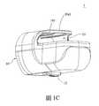
〔圖1C〕係以另一角度顯示本發明未設置傳感器時的外觀立體圖。[Fig. 1C] is a perspective view showing the appearance of the present invention without a sensor from another angle.
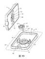
〔圖1D〕係以另一角度顯示本發明未設置傳感器時的外觀立體圖。[Figure 1D] is a perspective view showing the appearance of the present invention without a sensor from another angle.
〔圖1E〕係本發明之仰視圖。[Figure 1E] is a bottom view of the present invention.
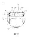
〔圖1F〕係本發明之後視圖。[Figure 1F] is a rear view of the present invention.
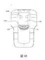
〔圖1G〕係本發明已設置傳感器時的之後上方視圖。[Figure 1G] is the rear top view of the present invention when the sensor has been installed.
〔圖2〕係本發明之爆炸圖。[Figure 2] is an exploded view of the present invention.
〔圖3A〕係本發明的傳感器於檢測時的外觀立體示意圖。[Fig. 3A] is a perspective view of the appearance of the sensor of the present invention during detection.
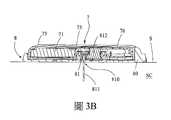
〔圖3B〕係本發明的傳感器於檢測時沿Y-Y方向的剖面圖。[Figure 3B] is a cross-sectional view of the sensor of the present invention along the Y-Y direction during detection.
〔圖3C〕係本發明的傳感器於檢測時沿X-X方向的剖面圖。[Figure 3C] is a cross-sectional view of the sensor of the present invention along the X-X direction during detection.
〔圖3D〕係本發明的傳感器與感測器模組分離的示意圖。[Fig. 3D] is a schematic diagram of the separation of the sensor and the sensor module of the present invention.
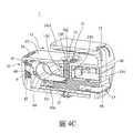
〔圖4A-4C〕係本發明的充電裝置縱向的不同切線側剖立體示意圖,揭示傳感器尚未放置於充電器上的狀態。[FIGS. 4A-4C] are perspective schematic diagrams of the charging device of the present invention with different tangents in the longitudinal direction, revealing the state that the sensor has not been placed on the charger.
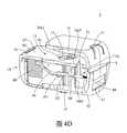
〔圖4D〕係本發明充電裝置的第一鎖定模組另一實施例示意圖。[Figure 4D] is a schematic diagram of another embodiment of the first locking module of the charging device of the present invention.
〔圖5A〕係本發明充電裝置的側剖立體圖,揭示傳感器放置於充電器上的狀態。[FIG. 5A] is a side-sectional perspective view of the charging device of the present invention, revealing the state of the sensor placed on the charger.
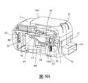
〔圖5B〕係本發明充電裝置的側剖立體圖,並且第二電連接埠從第一位置往第二位置移動的狀態。[Fig. 5B] is a side sectional perspective view of the charging device of the present invention, and the second electrical connection port moves from the first position to the second position.
〔圖5C〕係本發明充電裝置的側剖立體圖,揭示傳感器放置於充電器上的狀態,並且第二電連接埠從第一位置往第二位置移動的狀態,但隱去傳感器。[FIG. 5C] is a side sectional perspective view of the charging device of the present invention, revealing the state where the sensor is placed on the charger, and the second electrical connection port moves from the first position to the second position, but the sensor is hidden.
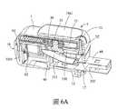
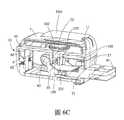
〔圖6A-6C〕係本發明的充電裝置縱向的不同切線側剖立體示意圖,揭示傳感器放置於充電器上並進行操作的狀態。[FIGS. 6A-6C] are perspective schematic diagrams of the charging device of the present invention with different tangents in the longitudinal direction, showing the state of the sensor being placed on the charger and operating.
〔圖6D〕係本發明的充電裝置後下方縱向側剖立體示意圖,揭示傳感器放置於充電器上並完成操作的狀態。[Fig. 6D] is a perspective schematic view of the rear and lower longitudinal side section of the charging device of the present invention, revealing the state where the sensor is placed on the charger and the operation is completed.
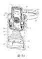
〔圖6E〕係本發明的充電裝置與各種外部電源連結的示意圖。[Figure 6E] is a schematic diagram of the connection between the charging device of the present invention and various external power sources.
〔圖7A-7B〕係本發明的充電裝置隱去本體後的內部立體示意圖。[Figures 7A-7B] is a three-dimensional schematic diagram of the interior of the charging device of the present invention with the body hidden.
〔圖7C〕係本發明充電裝置的另一實施例側剖視圖。[Figure 7C] is a side cross-sectional view of another embodiment of the charging device of the present invention.
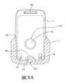
〔圖8A-8B〕係本發明充電裝置上設置傳感器的使用狀態上視剖面圖。[Figures 8A-8B] are the top cross-sectional views of the charging device of the present invention with sensors in use.
〔圖9A-9B〕係本發明具致動端另一實施例的充電裝置上設置傳感器的使用狀態上視剖面圖。[FIGS. 9A-9B] is a top cross-sectional view of a charging device with an actuating end of another embodiment of the present invention with a sensor installed on it.
〔圖10〕係本發明的第一導電接頭的接點示意圖。[Figure 10] is a schematic diagram of the contacts of the first conductive joint of the present invention.
〔圖11〕係本發明充電裝置與傳感器的電路示意圖。[Figure 11] is a schematic circuit diagram of the charging device and the sensor of the present invention.
〔圖12A〕係本發明充電裝置的防潮組件使用剖面立體圖。[Fig. 12A] is a cutaway perspective view of the moisture-proof component of the charging device of the present invention.
〔圖12B〕係本發明充電裝置的防潮組件使用外觀示意圖。[Figure 12B] is a schematic diagram of the appearance of the moisture-proof component of the charging device of the present invention.
〔圖12C〕係本發明充電裝置的防潮組件之蓋上蓋體後的使用剖面立體圖。[Figure 12C] is the moisture-proof component of the charging device of the present invention after the cover is coveredUse a cutaway perspective view.
〔圖12D〕係本發明充電裝置的另一實施例的防潮組件使用剖面立體圖。[Figure 12D] is a cross-sectional perspective view of the moisture-proof component of another embodiment of the charging device of the present invention.
〔圖12E〕係本發明充電裝置的另一實施例的防潮組件使用剖面立體圖。[Fig. 12E] is a cross-sectional perspective view of the moisture-proof component of another embodiment of the charging device of the present invention.
〔圖12F〕係本發明充電裝置的另一實施例的防潮組件使用剖面立體圖。[FIG. 12F] is a cross-sectional perspective view of the moisture-proof component of another embodiment of the charging device of the present invention.
〔圖13A-13B〕係本發明充電裝置的第三電連接埠之不同實施例的下方鏤空立體圖。[FIGS. 13A-13B] are hollow perspective views of different embodiments of the third electrical connection port of the charging device of the present invention.
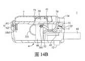
〔圖14A-14B〕係本發明充電裝置的另一實施例動作狀態的側面鏤空示意圖。[FIGS. 14A-14B] is a side view of a hollowed-out view of another embodiment of the charging device of the present invention in an action state.
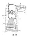
〔圖15〕係本發明充電裝置的另一實施例立體示意圖。[Figure 15] is a perspective view of another embodiment of the charging device of the present invention.
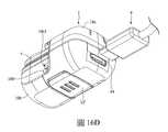
〔圖16A-16B〕係本發明充電裝置的另一實施例之斜前下方鏤空立體示意圖。[FIGS. 16A-16B] is a perspective view of another embodiment of the charging device of the present invention with a hollowed-out front and lower side.
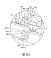
〔圖16C〕係圖16A-16B實施例的側剖面動作示意圖。[Fig. 16C] is a schematic diagram of the side cross-sectional action of the embodiment of Figs. 16A-16B.
〔圖16D〕係圖16A-16B實施例的斜前下方立體示意圖。[Figure 16D] is an oblique front and bottom perspective view of the embodiment of Figures 16A-16B.
〔圖16E〕係圖16A-16B實施例的局部分解立體示意圖。[Figure 16E] is a partial exploded perspective view of the embodiment of Figures 16A-16B.
請參閱圖1A至圖1G,透過各圖以不同的角度呈現以充分顯示各元件、各結構之間的相對位置與連結關係。其中揭示一充電裝置1,具有一本體10,通常是一殼體狀的物體,用以將所需的元件、結構設置並保護於其中。充電裝置1上還具有一置放部13,具有一承靠面13’以置放生理訊號傳感器7(以下說明簡稱為傳感器7),置放部13類似一插槽、或口袋狀結構,由蓋板10a1配合承靠面13’所形成,以側向插入傳感器7,於其他實施例中,置放部13亦不限為其他構型。於圖1B中,當傳感器7正確地置放於置放部13時,擋板61自擋板出口16中伸出以將傳感器7定位在置放部13中以免其脫離置放部13。於此同時電連接插頭44(或稱第三電連接埠)亦伸出於本體10外。於圖1A、圖1D中揭示了在置放部13內有一開孔(或稱升降通道)15以供第二電連接埠3’的充電座30在其內升降,亦即在第二電連接埠3’或充電座30的外面或頂部位置形成一置放部13。且為了避免充電座30不正常地運動,在開孔15內更設有導向部150(請配合圖5E),以避免充電座30在升降過程中的前後左右晃動或旋轉,而導向部150之間則形成一滑槽150’。此外,充電座30上固定了一第一導電接頭31,通常是金手指形式,用以與圖3D的傳感器7的第一電連接埠73電連接。此外,圖1C與圖1D揭示了在置放部13內具有上限制肋101設置於蓋板10a1內面,在蓋板10a1的兩側壁的內面則設置了側限制肋102,用以減少充電裝置1與傳感器7之間的接觸面積,以降低在充電裝置1內放置或取出傳感器7時的摩擦力。此外,限制肋亦有助於傳感器7定位於充電座,避免傳感器7晃動或不易取出。另於生產上殼體10a時,限制肋也有助於上殼體10a從模具上進行脫模。蓋板10a1用於遮蔽開孔15有利於靜電防護,亦可防止不當的外物碰到第一導電接頭31及/或充電座30。在另一實施例,充電裝置10亦可省略蓋板10a1或適度能適當地遮擋傳感器7的前方、側方、與上方即可。此外,用以控制操作模組4(請參閱圖2)的推拉鍵12則伸出於殼體10外,使用者即透過推拉鍵12來控制操作模組4的動作。Please refer to FIGS. 1A to 1G, which are presented from different angles to fully show the relative position and connection relationship between the components and the structures. A charging
請參閱圖1ID,揭示了當傳感器7未放置處於一預定位置,例如尚未放入或未正確地置放於置放部13內時,一致動端51伸出於置放部13內,致動端51屬於一第一鎖定模組5(又稱止擋模組),當傳感器7正確地置放於置放部13內時,致動端51即被壓掣而向下移動詳細的動作原理隨後將做說明(請參閱圖4C與6C)。1ID, it is revealed that when the
請參閱圖1E,推拉鍵12設於殼體10的底部,且還具有一定位塊120,而殼體10上則形成了對應的第一定位槽103a與第二定位槽103b,圖1E的定位塊120係與第一定位槽103a卡合以維持推拉鍵12在第一操作狀態,當使用者將推拉鍵12向殼體10內壓掣時,即可令定位塊120脫離與第一定位槽103a的卡合,接著推拉鍵12被推至第二定位槽103b時,定位塊120即可與之卡合(請配合圖6G)。請參閱圖1F,其中揭示了充電裝置1的後方(尾部)視圖,蓋板10a1內面設置了限制肋101,此外還可見到一第一配合部14,凸設於置放部13最深處。請參閱圖1G,揭示充電裝置1的置放部13的寬度W2小於或等於傳感器7的寬度W1,當使用者要取出傳感器7時可以很方便地從置放部13的左右兩側握持、夾住傳感器7而不會同時夾持到充電裝置1。1E, the push-
請參閱圖2,是本發明第一實施例的爆炸圖,其中可見在圖1的各圖中的殼體(本體)10更可分為上殼體10a與下殼體10b,上殼體10a包含了之前所述的指示區11、蓋板10a1、以及置放部13,置放部13上則形成一承靠面13’,其中大部份已於前面說明,於此不再贅述。傳感器7上形成一第二配合部70,如前所述,於圖2可見指示區11的形狀與第二配合部70形狀相仿,此設計可用於視覺化提醒使用者放入充電裝置的方向,充電裝置上的第一配合部14為一凸狀(請配合圖1F),傳感器的第二配合部70為一凹狀,當該第一配合部與該第二配合部相互結合則形成結構防呆,並使該第一連接埠73與該開孔15正確對位(圖未示)。Please refer to FIG. 2, which is an exploded view of the first embodiment of the present invention. It can be seen that the housing (body) 10 in each figure of FIG. 1 can be further divided into an
請繼續參閱圖2,充電裝置1包括一充電模組3,進一步包括第二電連接埠3’、電路組件33及第三連接埠44,第二連接埠3’包括充電座30,其上設有第一導電接頭31與一第二導電接頭32。第一導電接頭31通常是一金手指型接頭,用以傳輸電力與訊號;第二導電接頭32通常是一彈簧探針(Pogo Pin)作為接地之用。而在充電座30的側面則具有一第二導引結構301以做為一滑件,而第一滑件301則係透過一滑件座302設置於充電座30上。電路組件33,用於對該生理訊號傳感器進行充電及充電控制或是訊號傳輸控制,其一端是電路板330,設有一發光元件332及其他相關電子元件,且電連接至第一導電接頭31與第二導電接頭32。而發光元件332上方更有一導光元件52’設置於上殼體10a內,通常即位於第一配合部14(請配合圖1F)內,且形狀亦通常剛好契合指示區11,因而指示區11係以透明或半透明材料製成,或本身即做為導光元件52’之一部份,也就是說導光元件52’形狀即對應於第二配合部70,指示區11亦作為燈號區。電路組件33的另一端是可撓電連接件331,通常是一軟性電路板(Flexible print circuit),用以維持與作為第三電連接埠的電連接插頭44的電連接以輸入電源,可撓電連接件331亦可以滑針滑軌導電結構(Power Rail、Sliding Contact Line)取代。Please continue to refer to FIG. 2. The charging
請繼續參閱圖2,充電裝置1包括一操作模組4,進一步包括操作部40被用以驅動該第二電連接埠3’的充電座30與該傳感器的第一電連接埠73電連接,其操作部40上組設第三電連接埠44,並具有一第一導引結構41,通常是一滑軌、滑槽,與該第一滑件301相互耦合,當操作部40被驅動進行橫向移動時,第一導引結構41導引該第一滑件301縱向移動,進而帶動充電座30上下移動,因此第一滑件301亦作為一第二導引結構。此外,前述的推拉鍵12即設置於操作部40的下方,即使用者透過推拉鍵12驅動操作部40做橫向移動,詳細作動請配合圖7A及7B。推拉鍵12與操作部40可為一體成形或兩者分別為獨立元件。Please continue to refer to FIG. 2, the charging
請繼續參閱圖2,充電裝置1進一步包括一第一鎖定模組5(或稱止擋模組5、第一鎖定部5)可解除地限制該第二電連接埠3’移動,其中一端為致動端51,另一端為止擋端52,致動端51伸入置放部13內,即突出於承靠面13’,而止擋端52則與操作部40上設置的一受擋部43耦合,亦即受擋部43被止擋端52所止擋以至於不能橫向移動,因此,操作部40進而不能通過第一導引結構41導引該第一滑件301縱向移動,故第一鎖定模組5達到了間接限制該第二電連接埠3’移動的功效。此外,第一鎖定模組5更包括一彈性元件53,用以將致動端51於傳感器7未置放於置放部13時保持常態伸入置放部13,此時亦使止擋端52保持常態止擋受擋部43。而在致動端51與止擋端52之間具有一樞接部50,樞設於下殼體10b的樞設架10b2,當致動端51受到傳感器7的壓掣時第一鎖定模組5即可以樞接部50作為轉動中心而轉動並以樞設架10b2為支點轉動(詳細前後作動請配合圖4B及5A)。Please continue to refer to FIG. 2, the charging
請繼續參閱圖2,充電裝置1進一步包括一第二鎖定模組6(或稱第二鎖定部6、定位模組6、擋板61),設置於充電裝置1上靠後側的位置,並具有一擋板61可從擋板出口16處伸出而抵達置放部13,且具有一彈性元件62對擋板61提供一伸出擋板出口16的一彈力,第二鎖定部6還具有一第一銜接端60,用以銜接第二銜接端42。第二鎖定部6還有一導引結構63為一槽口,耦合於下殼體10b的一導引件10b1,使擋板61可以僅在上下方向移動而不會偏移、旋轉(詳細作動請配合圖4C及6C)。於其他實施例中,充電模組3、操作模組4、第一鎖定模組5或第二鎖定模組6的一部份可形成如同下殼體10b的殼罩結構,與上殼體10以形成一內部空間,以容納各元件(圖未示)。以上操作模組4、第一鎖定模組5及第二鎖定模組6合稱為控制模組用以控制傳感器7與該充電模組3之間的運行過程維持一安全狀態,使傳感器7與第二電連接埠3’之間形成分離或連接時,皆能受到保護,避免使用者操作不當而造成零件受損(詳細作動請參閱圖4A至圖6C)。於其他實施例中,第一鎖定模組5或第二鎖定模組6分別搭配操作模組4合稱為控制模組。Please continue to refer to FIG. 2, the charging
請參閱圖3A至圖3D。其中圖3A揭示了傳感器7可分離地蓋置於一感測器模組8上且連接該感測器組件81,而感測器模組8包括一感測底座80與感測器組件81,該底座80更可透過一貼布ST黏著於皮膚S上,此時傳感器7負責將來自感測器810的訊號傳輸至外界。原則上傳感器7為一可重複使用裝置,而感測器模組8為一次性使用裝置。Please refer to Figure 3A to Figure 3D. 3A shows that the
請參閱圖3B至3D,傳感器7內包括一電池71與第一電連接埠73,包括一輸入部730,輸入部730內具有一輸入端子732與一次要輸入端子733,其中輸入端子732位於一插孔731內。電池71為傳感器7的運作如訊號之輸出提供電力。第一電連接埠73為凹陷結構用以與傳感器組件81或第二電連接埠3’結構組配,輸入端子732用以與輸出端812或第一導電接頭31電連接。此外傳感器7還包括第一卡扣結構72用以與底座80的第二卡扣結構83相互卡扣致固定。感測器組件81固定於底座80的容置槽82內,感測器810的穿刺端811刺入皮下組織SC,而感測器810的輸出端812的則進入第一電連接埠73而與傳感器7內的輸入端子732電連接,所以感測器810所測得的信號可以藉由傳感器7傳送至外界。為了避免傳感器7以錯誤的方向設置於底座80上,底座80上更具有配合對位部84用以與第二配合部70相配合,藉此當使用者將傳感器7蓋設於底座80時,可直觀地經由結構外觀分辨其安裝的方向達到防呆的效果。本發明所述之傳感器7僅為一種實施例態樣,本發明充電裝置1亦可應用於其他態樣之傳感器。本發明使用的生理訊號傳感器7大致上包括一傳感器本體75,本體75內還包括一電路板76、一電連接於該電路板76的電池71、以及一第一電連接埠73,該第一電連接埠曝露於外。3B to 3D, the
請參閱圖4A至圖4D,其中呈現了充電裝置1未被放置傳感器7的狀態,關於其中各編號請配合圖2。請參閱圖4A及圖4B,充電模組3處於第一操作狀態,操作部40尚未驅動第二電連接埠3’位於開孔15內處於第一位置(相對承靠面13’為縮回狀態),亦即一非充電位置,開孔15內具有滑槽150’,電路組件33設於殼體10內,包括電路板330與電連接件331,其中電路板330上設有一發光元件332,且電路板330與充電座30內的第一導電接頭31電連接,而電連接件331為一可撓性材質與電連接插頭44電連接,通常係銲接在電連接插頭44的輸出端。上殼體10a前方的指示區11內具有導光件11’,而後方則具有擋板出口16,其內設有套設於導引結構10b1的擋板61。操作部40亦設置於殼體10內,其底部設有一推拉鍵12,且電連接插頭44亦與操作部40上的固定塊40a卡固。於另一實施例中推拉鍵亦可設計成其他驅動方式。Please refer to FIGS. 4A to 4D, which show the state where the
請參閱圖4A及4B,置放部13內對應於殼體10前方的位置則有第一配合部14,用以與傳感器7的第二配合部70相互配合(請同時配合圖1F)使傳感器7放置於一預定位置。當操作模組4處於第一操作狀態,其中操作部40的第一導引結構41耦合於充電座30的第二導引結構301,此時第二導引結構301尚未於第一導引結構內41滑動。以圖4B而言,第一導引結構41係斜狀溝槽,具有斜面,因此係以斜面導引第二導引結構301的移動。操作部40具有一受擋部43被第一鎖定模組5的止擋端52所鎖定或止擋,因此當推拉鍵12受到外力而欲帶動操作部40時,或操作部40本身因為晃動時,第一導引結構41不會帶動第二導引結構301,從而避免了第二電連接埠3’的充電座30被意外驅動往第二位置方向(相對承靠面13’為伸出狀態)。另外由於第一導電接頭31較為輕薄短小,亦可避免使用者若欲將傳感器7強行取放而導致第一導電接頭31損毀的問題。圖4B還揭示了第一鎖定模組5的致動端51伸入置放部13的位置。致動端51與止擋端52之間更具有一樞接部50樞設於下殼體10b的樞設架10b2上,因此第一鎖定模組5即類似於一蹺板結構,當致動端51被壓下時,止擋端52即上揚(請參考圖5A)。又,一彈性元件53連接了第一鎖定模組與下殼體10b,並為第一鎖定模組5提供彈力以在傳感器未放入充電裝置1的情形時(即致動端51不被壓下的狀態時)維持致動端51突出於承靠面13’。4A and 4B, the position corresponding to the front of the
請參閱圖4C,揭示當第二導引結構301未被第一導引結構41帶動時,滑件座302未跟著第二導引結構301移動,為了避免充電座30以非預期的方向移動,本發明在開孔15外側更鄰設至少一導向部150以形成一滑槽150’,使滑槽150’與該開孔15互相連通,使滑件座302在滑槽150’內導引充電座30以一固定方向從該開孔15內升降,第二鎖定部6還具有一第一銜接端60,當操作部40處於第一操作狀態時,操作部40處於第一位置,第一銜接端60與操作部40上的第二銜接端42接合,以阻止擋板61被彈性元件62推動,此時充電座30處於一第一位置(相對承靠面13’為縮回狀態),使第二鎖定部6壓下以使擋板61維持在擋板出口16內,即不伸出擋板出口16,使第二鎖定部6解除對傳感器7的定位,使得傳感器7可從置放部13放入或取出。Referring to FIG. 4C, it is revealed that when the
請參閱圖4D,揭示了本發明充電裝置的第一鎖定模組另一實施例。其中第一鎖定模組替換成了一鎖定滑塊5,具有一滑動本體50,其一端是致動端51、另一端是止擋端52,而充電模組3的第二導引結構301則突出於第一導引結構41之外且其上方被止擋端52所阻擋,在傳感器7未放入置放部13時,鎖定滑塊5由於受到彈簧53的常態向擋板61的方向(即置放部13的開口方向)推動的力量。因此當第二導引結構301被第一導引結構41推動向上時會被止擋端52所阻擋而無法上升。之後,當傳感器7以正確的方向,即第二配合部70朝內的方向,插入置放部13後,傳感器7即可推動致動端51向置放部13更深處移動,並進而帶動鎖定滑塊5以同一方向移動,此時即令止擋端52離開第二導引結構301的上方,故而當使用者透過推拉鍵12帶動第一導引結構41時,即帶動第二導引結構301上升,亦即帶動第二電連接埠3’上升,止擋端52亦不再繼續阻擋第二導引結構301。如上述實施例所示,第一鎖定模組除了透過自身與充電模組或操作模組可解除地耦合以限制第二電連接埠3’的移動之外,當第一鎖定模組限制第二電連接埠3’移動可能是完全禁止或者僅能部分位移但無法與第一連接埠73(圖3D)作有效接觸之狀態。Please refer to FIG. 4D, which discloses another embodiment of the first locking module of the charging device of the present invention. The first locking module is replaced with a locking
請一同參閱圖5A至圖5C,其中分別揭示了當傳感器7放入充電裝置1的預定位置的狀態及操作部40被控制驅動第二電連接埠3’伸出該承靠面13’之狀態,關於其中各元件編號請配合圖2,圖3A至圖3D。其中與上述各圖重覆的元件於此不贅述。請參閱圖5A為傳感器7放置於承靠面13’的一預定位置的狀態,即使傳感器7處於一正確相對位置時,該致動端51經由受該傳感器7的致動以偵測傳感器7是否處於一預定位置,當傳感器7處於該預定位置,該止擋端52解除操作部40的鎖定,以許該操作部40驅動第二電連接埠3’於第一位置與第二位置之間移動,並與該第一電連接埠73形成連接或分離。於圖5A中,當傳感器7處於預定位置,傳感器7壓下致動端51使第一鎖定模組5轉動,同時使止擋端52蹺起而解除了對受擋部43的止擋以解除第二電連接埠3’的移動限制。此時的彈性元件53則受到壓縮,而當傳感器被取出後,其彈性元件53之彈性回復力則會驅使致動端51向上伸進置放部13(如圖4B的狀態)。Please refer to FIGS. 5A to 5C together, which respectively disclose the state when the
請參閱圖5B至圖5C為操作部40被控制驅動第二電連接埠3’從第一位置往第二位置移動的狀態,當置放部13本身於傳感器7置入後,並且推拉鍵12被操作成推出一部分的電連接插頭44時,以圖5B-5D的方向而言是向右推動時,當第一鎖定模組5(第一鎖定部5)的止擋端52已蹺起而不再止擋受擋部43,使第二電連接埠3’解除移動限制,推拉鍵12即帶動操作部40以同方向移動。此時第一導引結構41即推動第二導引結構301向上移動,並進而帶動充電座30從開孔15往上移動並朝向傳感器7的第一電連接埠73移動(配合圖3D、圖6A),同時使第一導電接頭31往插孔731移動(配合圖3C),同時,電連接插頭44則部分伸出開口17。此外,當操作部40向右移動時,第二銜接端42脫離了第二鎖定部6的第一銜接端60(如圖5C),因此原本受到壓掣的彈性元件62的彈力位能得以釋放以將擋板61推出擋板出口16並止擋了傳感器7的尾端而達到將傳感器7定位於置放部13上的功效。請參閱圖5C,為隱去傳感器7以較為清楚的描繪置放部13本身於傳感器7置入後,並且推拉鍵12被操作成推出一部分的電連接插頭44時的狀態,以及充電座30及其第一導電接頭31於開孔15內的上升途中時的位置。Please refer to FIGS. 5B to 5C for a state in which the operating
請一同參閱圖6A至圖6D,其中揭示了傳感器插入後,操作部40被控制驅動第二電連接埠3’處於第二位置的狀態,並且電連接插頭44已被完整推出的狀態,關於其中各元件編號請配合圖2,圖3A至圖3D。其中與上述各圖重覆的元件於此不贅述。請參閱圖6A及圖6B,當第一鎖定模組5對操作部40的移動限制被解除,操作部40驅動第二電連接埠3’從開孔15從第一位置移動至第二位置(相對承靠面13’的為伸出狀態)與第一連接埠73電連接,即位於一充電位置,其中充電座30從開孔15伸出完成了與輸入部730的結合,使第一導電接頭31進入插孔731與傳感器7之輸入端子732電連接(如圖3C所示位置)。而推拉鍵12則被推到了殼體10前方,以圖面而言即最右方,且電連接插頭44亦完全伸出開口17。此時電路板330亦抬升到最高處,而此時發光元件332最接近導光元件52’,此時發光元件332的發光狀態即可藉由導光元件52’傳遞到指示區11上並使整體作動行程兼具防呆與導光效果,並有效利用充電裝置1的內部空間,使充電裝置微小化。此時發光元件332已在預備發光的狀態,當電連接插頭44插入一外部電源,例如AC電源適配器、電腦USB插座、車用充電適配器、或配有USB插座的裝置,請配合圖6E充電器1可以插在個人電腦91上的USB插座、手機充電器92上或車用點菸器轉接器93(car cigarette light usb adapter)等等,使發光元件332即可發光提供訊息指示,並以不同的發光顏色、模式來表示充電器1的使用狀態。Please refer to FIGS. 6A to 6D together. After the sensor is inserted, the operating
請參閱圖6C,操作模組4處於第二操作狀態,其中可見當推拉鍵12向殼體10的前端方向推到底時,操作部40也到了最靠近殼體10前端的位置,此時第二導引結構301亦被第一導引結構41推升到最高位置。相對的,電連接插頭44在圖6C為推出狀態,而在圖4C是縮回狀態,圖6C揭示了滑件座302亦上升到滑槽150’的高位,第二鎖定部6(擋板61)的第二銜接端42脫離第一銜接端60,因此原本受到壓掣的彈性元件62的彈力位能得以釋放以將擋板61推出擋板出口16並止擋了傳感器7的尾端而達到將傳感器7定位於置放部13上,以對傳感器7進行定位並鎖定傳感器7被取放,以避免電連接中的第一電連接埠73與該第二連接埠3’因意外地取放傳感器7而而損壞第二連接埠3’。更進一步地,此時第二電連接埠3’處於一第二位置(相對承靠面13’為伸出狀態),擋板61伸出擋板出口61,使第二鎖定部6定位傳感器7於承靠面13’位置,使傳感器7無法從置放部13放入或取出以保護第二電連接埠3’之第一導電接頭31避免遭受傳感器7不當操作而受損。當充電模組3處於第三操作狀態,即當操作部40驅動第二電連接埠3’自第二位置移回第一位置以分離該第一電連接埠73,且該操作部40,透過第二銜接端42壓掣第一銜接端60並連動擋板61降下後(操作狀態如同圖4C),驅使第二鎖定部6縮回該承靠面13’以解除對傳感器7的定位鎖定,使得該第一連接埠73及第二連接埠3’處於分離狀態時,才可取放傳感器7。請參閱圖6D,在一實施例中揭示推拉鍵12位於最靠近殼體10前端的位置,而定位塊120於此同時可以卡合至第二定位槽103b內,於充電完成後,則先將電連接插頭44斷開與外部電源的連接,將推拉鍵12向殼體10內壓掣時(請配合圖1E說明),使定位塊120脫離第二定位槽103b,此時及可將推拉鍵12朝向第一定位槽103a推動,最後定位塊120即回到第一定位槽103a內,此時充電座30完全降下,擋板61亦回到擋板出口16內而不再擋住傳感器7,此時即可將傳感器7自置放部13上取下,由此可見推拉鍵12的操作進一步搭配定位塊120與第一定位槽103a及第二定位槽103b之間的定位方式,可降低使用者因操作不當或意外移動、晃動所造成的開口17的以及第一電連接埠73與第二電連接埠3’之間的摩擦耗損,以提升充電裝置1整體操作結構的耐用性。於另一實施例中,推拉鍵之滑動設計不需經由向殼體10內壓掣之動作。6C, the
請一同參閱圖7A與7B,關於其中各元件編號請配合圖2及其它圖式說明,其中將殼體10移除以完整揭示操作模組4與充電模組3之間的相對位置與連結關係。其中圖7A是本發明於第一操作狀態,而第二導引結構301位於第一導引結構41內的第一位置,通常是低處,使第二電連接埠3’的充電座30保持在與承靠面13’相對縮回位置。由之前的圖式及說明可知充電座30係僅能上下移動,因此為了避免因上下晃動而導致充電座30意外的上下移動進而帶動操作模組4,因此,本發明的第一導引結構41為一導槽結構,於第一位置更延伸形成一第一橫槽41a,其延伸方向垂直於第二導引結構301的移動方向,故當充電模組1產生平行於充電座30移動方向的晃動時,第一橫槽41a由於其延伸方向垂直於第二導引結構301的移動方向,故而可以阻止充電座30因為該晃動而移動。圖7B是本發明於第二操作狀態,操作部40被往前推,使第二導引結構301位於第一導引結構41內的第二位置,通常是高處,使充電座30保持在與承靠面相對伸出位置。本發明的第一導引結構41於第二位置更延伸形成一第二橫槽41b,其延伸方向垂直於第二導引結構301的移動方向,以免充電座30因為有一平行於其移動方向的晃動而移動。請繼續圖7A與圖7B並配合圖2,第一導電接頭31與第二導電接頭32插設於電路板330上,而圖7B的充電模組3(圖2)已在可充電的狀態。Please refer to Figures 7A and 7B together. Please refer to Figure 2 and other drawings for the component numbers. The
請參閱圖7C,係本發明充電模組與操作模組的另一實施立側剖面圖。其中揭示擋板61透過一連接件6’直接連動於充電座30,使得兩者的升降完全同步,而充電座30亦可與擋板61、連接件6’一體成形,換言之,充電模組3可以與作為第二鎖定模組的擋板61一體成形。操作模組4與充電模組3之間以磁力藕合作動,其中充電模組3的下方具有一第一磁力元件MP1,而操作模組4上則具有一第二磁力元件MP2與一第三磁力元件MP3,且第一磁力元件MP1與第二磁力元件MP2極性相斥,而與第三磁力元件MP3相吸,因此當操作模組4位於第二操作狀態(被向右推到底)時,第二磁力元件MP2位於第一磁力元件MP1下方,透過斥力將充電模組3向上推動,且同時帶動擋板61向上伸出擋板出口16。又,當操作模組4位於第一操作狀態(被向左推到底)時,第三磁力元件MP3位於第一磁力元件MP1下方,透過吸力將充電模組3向下拉動,且同時帶動擋板61向下縮回擋板出口16。Please refer to FIG. 7C, which is another example of the charging module and the operating module of the present inventionOne implementation vertical side sectional view. It is disclosed that the
請一同參閱圖8A至圖9B,關於其中各元件編號請配合圖2及其它圖式。其中與上述各圖重覆的元件及動作說明於此不贅述。請參閱圖8A與圖9A,均係本發明充電模組上設置傳感器的使用狀態上視剖面圖。其中可見傳感器7已置放於置放部13上,而第二配合部70配合於第一配合部14,使傳感器7處於一正確相對位置或預定位置,此時第一連接埠73正對準了開孔15,故當充電座30(請配合圖6A)升起時可以正確的與第一連接埠73電連接。其中圖8A與圖8B,致動端51的位置於橫向方向上大致等同於第一配合部14的位置,因此僅有當傳感器7抵達行程的末端時才能壓掣致動端51使第一鎖定模組5轉動而不再止擋受擋部43(請參考圖5A),致動端51設置在承靠面13’的末端可減少與傳感器7底部的摩擦力。於其他實施例中則不限定致動端51位於其他位置。更進一步而言,由於第一配合部14係為向置放部13內延伸的一凸出狀的結構(如圖1F所示),因此在其兩側自然形成凹陷區域,而致動端51即設置於此凹陷區域內。相對的,傳感器7的第二配合部70則是一向內形成的凹陷結構,因此在第二配合部70的兩側即形成凸出結構,故當第二配合部70配合於第一配合部14時,第二配合部70兩側的二凸出結構即會進入該凹陷區域內,進而使凸出結構觸動致動端51使止擋端52蹺起不再阻擋受擋部43,此時擋板61即可自擋板出口16伸出以擋住傳感器7的尾端底面,以達將傳感器7鎖定住的功效。在圖8B中,當傳感器以錯誤方向插入充電器1,若以傳感器7尾端進入置放部13,由於被第一配合部14阻擋,傳感器7的前端壓掣於擋板61上方,使擋板61無法自擋板出口16伸出,且第一電連接埠73亦未對準開孔15,於此同時,由於傳感器7的尾端無法抵達插入行程的末端,導致傳感器7無法壓掣致動端51故而止擋端52仍繼續阻擋受擋部43,故操作部40無法移動,進而充電座30亦無法從開孔15頂面露出,防止第一導電接頭31不正常碰撞到傳感器7而可能的毀損以延長充電裝置1的使用壽命,亦即此時為一安全狀態係可防止第二電連接埠3’上的如第一導電接頭31撞擊傳感器7。此時第二銜接端42亦仍限制住第一銜接端60使得擋板61無法伸出,於此現象發生時亦可做為提醒使用者有發生傳感器7放置方向錯誤。Please refer to FIG. 8A to FIG. 9B together. Please refer to FIG. 2 and other drawings for the number of each component. The descriptions of the components and actions that are repeated with the above figures are not repeated here. Please refer to FIG. 8A and FIG. 9A, both of which are the top cross-sectional views of the charging module of the present invention when the sensor is used. It can be seen that the
請參閱圖9A與圖9B,相較於圖8A及圖8B,致動端51設置在遠離凹陷區域之處,傳感器7放置過程中,二凸出結構先壓掣致動端51使止擋端52蹺起不再阻擋受擋部43後,才會進入該凹陷區域內與第一配合部14接合,而擋板61即可自擋板出口16伸出以擋住傳感器7的尾端。在圖9B中,當傳感器以錯誤方向插入充電器1,由於傳感器7以尾端進入置放部13,因此使傳感器7的前端底部壓掣於擋板61上方而使擋板61無法自擋板出口16伸出,且第一電連接埠73亦未對準開孔15,於此同時,雖然傳感器7雖可觸動致動端51並令止擋端52蹺起不再阻擋受擋部43,但操作部40可移動距離被控制至少使第一導電接頭31無法從開孔15頂面露出,以防止傳感器7底部及第一導電接頭31不當操作而受損,此時僅能推出電連接插頭44的一部份,故仍可做為提醒使用者此時出現了傳感器7置放方向的錯誤,亦即此時為一安全狀態係可防止第二電連接埠3’上的如第一導電接頭31撞擊傳感器7。Please refer to Figures 9A and 9B. Compared with Figures 8A and 8B, the actuating
請一同參閱圖10,係本發明的第一導電接頭的接點示意圖,第一導電接頭31呈現為但不限於金手指狀接點,且第一導電接頭31接觸端310構型與感測器輸出端812構型相同(如圖3B-3D所示),故接觸端310與輸出端812皆可適用插入傳感器7的第一電連接埠73的插孔731內,因此第一導電接頭31可以與輸出端812共用第一電連接埠73以節省傳感器7的內部空間。請繼續參閱圖10,並同時參閱圖11,圖11係本發明充電裝置與傳感器的電路示意圖,其中揭示充電器1內的電路組件33具有一充電電路組1A以及校正電路組1B,第一導電接頭31接觸端310呈現但不限為8個接點BAT、SW、RX、TX、E1、E2、E3、E4,可配合感測器輸出端812接點數量而調整。充電電路組1A電連接第三電連接埠44以輸入電源,充電電路組1A用於提供及控制一充電電壓,充電電路組件1A再通過接點VBAT對傳感器7充電以輸出該充電電壓對傳感器7充電,接點SW作為充電開關。其餘接點則用於連接充電裝置1的校正電路組1B與傳感器7的傳感模組74,以利進行傳感器功能檢測包括數據傳輸、控制偵測自我校正、洩漏電流測量和/或電阻測量之功能。在另一實施例中,充電裝置1亦可僅提供充電功能。Please refer to FIG. 10 together, which is a schematic diagram of the contacts of the first conductive connector of the present invention. The first
請參閱圖12A至圖12F其中圖12A揭示一防潮組件2,具有大致呈罐體態樣的一殼體20,例如為圓柱形、橢圓柱形或扁圓柱型罐體至少其一,用以容納該充電裝置1或傳感器7或含有傳感器7的充電裝置1以形成一防潮組件2,防潮組件2並具有一開口23’,開口23’旁形成一第一卡扣緣23,而開口23’具有垂直於開口23’的一開口方向,第一卡扣緣23的突出方向則垂直於開口方向。一蓋體24,可活動地設置於該殼體20上,並用以密封該開口23’。其中,在蓋體24的內側亦形成一第二卡扣緣25,其突出的方向相對於第一卡扣緣23以使兩者相互卡扣。又,殼體20內具有一彈性元件22,當充電裝置1被置於殼體20內且蓋體24密封開口23’時,充電裝置1受到蓋體24的壓掣而縮入該殼體20內,從而使彈性元件22受到彈性變形(請配合圖12C),而當蓋體24開啟後,彈形元件22即釋放彈力位能而將充電裝置1推出,而使充電裝置1的至少一部分外凸殼體外,以利使用者取出(如圖12B),當傳感器7具有充電需求時,該充電裝置1從該殼體20內取出,用以連接外部電源為傳感器7進行充電。彈性元件22可為壓縮彈簧,例如錐狀彈簧、線圈彈簧、螺旋彈簧等,使彈性件22透過與充電裝置1具有干涉關係,可兼具固定配件在容器內的位置,避免晃動,如圖12C使用了錐形彈簧,由於錐形彈簧由上而下的各圈直徑明顯增加,因此當如圖12C所示蓋體24封住開口23’進而將充電裝置1壓入殼體20內,而充電裝置1再壓縮彈性元件22時,上一圈的彈簧圈可以被壓入下一圈的彈簧圈之內,所以比一般的筒狀螺旋彈簧的好處在於可以壓縮至更短的長度,有利於縮減防潮組件體積。當充電裝置為放入狀態,彈簧壓縮高度Hcompress加上充電裝置長度H1小於殼體高度H2,當充電裝置為取出狀態,彈簧伸展高度Hextend加上充電裝置長度H1大於殼體高度H2。請繼續參閱圖12A與12C,其中殼體20更分為第一容置空間20’與第二容置空間21,第一容置空間20’用以存放充電裝置1,而第二容置空間21用以容納乾燥劑29,兩者之間隔著一孔洞結構28,使得第一容置空間20’內的濕氣可以穿過孔洞結構28抵達第二容置空間21,並由乾燥劑29吸收濕氣,用以防止傳感器7受潮。依照第一實施例揭露的傳感器7約為32.8毫米*19.8毫米*4.15毫米(+/- 0.5毫米),充電裝置1的尺寸約為40 * 26 * 23毫米(+/- 0.5毫米),傳感器裝設於充電器上,而防潮組件2的體積不大於200立方公分,或介於12~138立方公分之間、或介於25~100立方公分之間、或介於30~70立方公分之間。其直徑範圍設計於2至5公分或長度乘以寬度控在約3至28平分公分,高度設計於4至7公分,使防潮組件的體積微小化,方便使用者攜帶。Please refer to FIGS. 12A to 12F. FIG. 12A shows a moisture-
請參閱圖12D至圖12F,揭示了傳感器7置放於防潮組件2之內的其他實施例,於圖12D中揭示了在有設置孔洞結構28的防潮組件2內僅放置了傳感器7的狀態,乾燥劑29亦設置於殼體20內,例如底部。於圖12E則揭示彈性元件22即直接設置於殼體20的底部,乾燥劑29亦設置於殼體20內。此外,乾燥劑29亦可選擇性設置在蓋體24的內面,當打開殼體20後,乾燥劑29即朝外,方便被更換。至於圖12F則揭示了在有設置孔洞結構28的防潮組件2內僅放置了傳感器7的狀態。在另一實施例中,乾燥劑29可一體成形於殼體或內壁,而使殼體20不須區分不同容置空間(圖未式)。此外,受推部27則便於使用者將蓋體24開啟。利用防潮組件2可以在不使用充電裝置1的時候將之妥善保護並隔絕外界濕氣,且進一步利用內部的乾燥劑對傳感器7及/或充電裝置1進行除濕以延長使用期限,避免濕氣造成電子零件受損。殼體20亦可設有類似於觀察區21’的結構,觀察區係為殼體的一部份(局部)以透明或半透明材料射出成型,若使用吸濕變色的乾燥劑或有額外的乾燥指示元件(圖未示)則可以很容易查看傳感器7及/或充電裝置1之受潮狀態。Referring to FIGS. 12D to 12F, other embodiments in which the
防潮組件2的使用方法為,同時提供第一傳感器與第二傳感器給使用者,其中第一防潮組件包含第一個傳感器與防潮組件2,第二防潮組件包含第二個傳感器與充電裝置結合並放置於防潮組件2內。使用者會先使用第一傳感器進行量測,當第一傳感器的電量低至一底限值,從底座上取下,並從防潮組件2中取出第二傳感器與充電裝置1,第二傳感器用於安裝於底座上,而第一傳感器則放入充電裝置2的置放部13進行第一傳感器充電,待充電完畢後再將第一傳感器結合充電裝置之組件放回防潮組件2儲存,而使第一傳感器與第二傳感器可被交替充電與使用。其中用於第一傳感器的防潮組件2為任一形式之容器中。The method of using the moisture-
請參閱圖13A,係本發明充電裝置的另一實施例,並請配合圖2。與之前各實施例不同的是充電裝置1是透過電線331’將第三電連接埠(USB插座44’)與第二連接埠3’的電路板330相互電連接。電線331’亦具有一定的柔性以適應充電模組3的升降而彎曲。此外,圖13A與之前實施例不同之處在於其第三電連接埠以一USB插座44’取代電連接插頭44(USB插頭),且更與一充電電池46及電源電路板47組成電力儲存單元45,藉由電力儲存單元45與充電模組3電連接用以輸入電力對傳感器7進行充電。此外,使用者也可將USB插座44’連接一外部電源對充電電池46重複補充電力,以增加使用方便性。另一實施例中,電力儲存單元45可省略USB插座,搭配一次性使用電池,例如市面上常見的乾電池、鈕扣電池等。在另一實施例中,亦可省略充電電池46,將USB插座44’連接一外部電源9(圖13B,以及圖6E的標號91、92、93)來供電進行傳感器7充電。至於圖2所示的操作模組4的操作部40雖未於圖13A揭露,但於實際上於本實施例仍有使用,僅是因為會遮蔽到電力儲存單元45故未於本圖繪出,而操作部40與充電模組3的第二電連接埠3’之間的連結關係與連動方式主要是通過第一導引結構41與第二導引結構301之間的耦合,兩者之間的動作關係一如前述。但與之前的實施例不同的是,圖13A、圖13B的操作部40並不與USB插座44’(第三電連接埠)固定,相對的,USB插座44’僅固定於充電裝置1內,而插座44’的插孔外露,因此當推拉鍵12被操作時只會通過第一導引結構41帶動第二導引結構301,而USB插座44’則不移動。圖13A其它元件的功效亦請參閱之前的圖式及說明,於此不再贅述。Please refer to FIG. 13A, which is another embodiment of the charging device of the present invention, and please cooperate with FIG. 2. The difference from the previous embodiments is that the
請參閱圖13B,係本發明充電裝置的另一實施例,並請配合參閱圖2,圖13B與圖13A實施例最大不同在於電力儲存單元45透過圈狀電線331”將電源電路板47電連接至充電座30用的電路板330。基本上仍透過充電裝置1具有推拉鍵12(圖13B未示)的位移帶動第二電連接埠3’的充電座30與電路板330的升降,進而間接帶動圈狀電線331”的伸縮變化。另一實施例中,圈狀電線331”亦可使用彈簧連接器(POGO pin)取代,至於其它元件的功效亦請參閱之前的圖式及說明,於此不再贅述。於圖13A及13B,作為第三電連接埠的USB插座44’則被設計成無須來回移動。Please refer to FIG. 13B, which is another embodiment of the charging device of the present invention. Please also refer to FIG. 2. The biggest difference between the embodiment of FIG. 13B and FIG. To the
請參閱圖14A與14B,揭示了充電裝置的另一種實施例。其中該充電裝置1包括一放置座13用以置放傳感器7,放置座13還包括一承靠面13’以放置該傳感器7,且承靠面13’包括開孔15(圖4A)。而在相對承靠面13’的對側設置一充電模組3,包括第二電連接埠3’、電路組件33及第三電連接埠44,第二電連接埠3’被配置於一開孔15(請參閱圖4A)內,用於與該第一電連接埠73(請參閱圖3D)進行電連接,第三電連接埠44,用於連接一外部或內部電源(請配合圖6E的標號91、92、93或參閱圖13B的標號46),電路組件33(請參考圖2)則連接第二電連接埠3’與第三電連接埠44之間,用以對該生理訊號傳感器7進行充電及充電控制。相對承靠面13’的對側還設置了控制模組,用以控制該傳感器7與該充電模組3之間的安全運行,包括一操作部40,操作部40用以驅動該第二電連接埠3’與該第一電連接埠73進行電連接。相對承靠面13’的對側還設置了一第一鎖定部5,可解除地限制該第二電連接埠3’與該第一電連接埠73之間的電連接抑或更進一步地用以可解除地限制第二電連接埠3’的位移,詳細第一鎖定部5的作動請參照圖4B、5A及6B說明,於此不再贅述。請參閱圖14A與14B,承靠面13’上相對於指示區11的另一端則設有第二鎖定部61,可伸縮於該承靠面13’,用以固定傳感器7的位置。進一步而言,第二鎖定部6包括一擋板61,擋板61套設於一導桿10b3而可上下平移,並通過一彈簧62’連接至承靠面13’的下方,且通過彈簧62’所提供的彈力而使擋板61常態維持突出於承靠面13’上。並請參閱圖14A至圖14B,當傳感器7被放置於承靠面13’時,放置過程中傳感器7會先將擋板61壓掣縮入承靠面13’,當第一配合部14與第二配合部70相配合之後,傳感器7剛好離開擋板61的上方而不再阻擋之,此時擋板61受到彈簧62’的彈性回復力的施力而再次突出於承靠面13’上。而當欲取出傳感器7時,首先通過將推拉鍵12向左推動使充電座30下降以解除電連接,之後只要再將擋板61壓入承靠面13’下使之不再阻擋傳感器7的尾部,即可將傳感器7向左平移而離開承靠面13’與置放部13。圖14A與14B中所示的第二鎖定部6的特徵亦可應用於本發明其它充電裝置的實施例,如以圖1A而言,即可將縮入承靠面13’下的擋板61視為是被使用者所壓下以利將傳感器7插入置放部13,使用者亦可如圖14A所示之直接通過傳感器7壓下擋板61,且在置放的過程當中,若第二配合部70正確的被朝內插入置放部13使之與第一配合部11相配合以達到傳感器7位於正確相對位置的結果,則擋板61會因傳感器7抵達了置放不13較深的位置而不再被傳感器7所阻擋而可受彈性元件62(圖2、圖5B)的回復力的推動而重新凸出於承靠面13’上。由此可見,若採用了圖14A與圖14B的擋板61,則第二鎖定部6的第一銜接端60與操作部40的第二銜接端42即可取消而不設置。Please refer to FIGS. 14A and 14B, another embodiment of the charging device is disclosed. The charging
請參閱圖15,其中揭示了不具備蓋板10a1的實施例,因此,承靠面13’本身即做為置放部,且在承靠面13’的一端設置了指示區11作為第一配合部可提供視覺提示的效果以令使用者可以將第二配合部70與之銜接、配合、接合在一起。而第一鎖定模組5(圖2、圖4B)的致動端51(圖1D、圖1F、圖2、圖4B)亦突出於承靠面13’上。還有,在承靠面13’的另一端則設置一擋板出口16,擋板61(圖2、圖4C、圖5C)即位於其中。由於本實施例中沒有蓋板10a1,為了防止傳感器7向上(即承靠面13’的軸線方向)脫離,在承靠面13’上更設置了如同圖3D所示的底座80上的第二卡扣結構83,用以與傳感器7的第一卡扣結構72來產生相互卡扣的效果,並使傳感器7得以固定於承靠面13’上。此外,為了使傳感器7在承靠面13’上可以更加地穩固而不會因意外撞擊而脫落,在承靠面13’上更形成側壁102’,通常成對設置,即位於承靠面13’的兩側,當傳感器7固定於承靠面13’後,側壁102’即貼合傳感器7的兩側,以達到在側向方向上協助固定傳感器7的功效。至於其它元件的功效亦請參閱之前的圖式及說明,於此不再贅述。Please refer to FIG. 15, which discloses an embodiment without a cover plate 10a1. Therefore, the bearing
請參閱圖16A至圖16B,為充電裝置的另一實施例,其中除了按壓鍵12’、第一鎖定模組5的止擋端52與閃避缺口52’等元件、結構與前面各圖的實施例不同外,其餘的元件、結構均與之前者相同,第二連接埠3’(或充電座30)係上升、下降的移動方式。故本實施例的第二連接埠3’係連接按壓鍵12’來驅動充電座30的升降,通常是一按鈕式鎖梢(latch button)的結構,按壓件12’亦可作為充電模組1的一部分或獨立的操作元件,按壓一次時,令充電座30上升並卡住停留,再按壓一次時,解除鎖定並回到原位、即未按壓時的位置,在操作按壓鍵12’的同時,充電座30的第二滑件302亦於兩個導向部150之間上下滑動。或是通過定位按鈕180對按壓鍵12’予以定位,詳細將於後面說明。請參閱圖16A,揭示了傳感器7尚未插入置放部13,故而此時止檔模組5的致動端51亦是伸入置放部13內(請參考圖1D)。此時若按壓鍵12’在被壓入本體時,止擋端52即對受擋部43產生阻擋的效果,進而阻擋充電座30進入置放部13。於另一實施例中受擋部43亦可能形成於充電座30(圖未示),或是於又一實施例中使用如圖4D的鎖定滑塊5。請參閱圖16B,揭示了傳感器7已插入置放部13,故而此時致動端51已被傳感器7壓下,進而使第一鎖定模組5轉動而使得閃避缺口52’對準了受擋部43,換言之,就是使止擋端52離開受擋部43的上方,此時若按壓鍵12’在被壓入本體時,受擋部43即可通過閃避缺口52’而能繼續上升,使充電座30進入置放部13。當按壓鍵12’向內移動時,止擋端52相對的進入閃避空間43’以免與按壓鍵12’產生干涉。此外,如圖16C及16D所示,上殼體10a的樞接架10a2與下殼體10b的樞接架10b2一同以可轉動的方式夾持住第一鎖定模組5的樞接部50。下殼體10b還具有一阻推結構10b3用以阻止止擋端52的運動,以免致動端51過度伸入置放部13內。充電裝置1還包括第二鎖定模組6,其設有一定位部61,連接一彈性單元62(如圖5C、圖6A),因此可升降地伸出該承靠面13’以鎖定生理訊號傳感器7的裝設位置。Please refer to FIGS. 16A to 16B, which are another embodiment of the charging device, in which the components and structures except for the pressing button 12', the stop end 52 of the
請參閱圖16E,為了可以充分觀察定位按鈕180與定位槽10b3之間的關係,定位按鈕180已自定位槽10b3內移至上方。定位槽10b3內具有成對設置的第一定位塊10b31與第二定位塊10b32。第一定位塊10b31的下方是第一狀態位置10b31p,即按壓鍵12’位於最下方時的位置,通過第一定位塊10b31可以阻擋定位肩180a,進而妨礙定位按鈕180向上移動,即達到阻擋按壓鍵12’向上移動的效果。第二定位塊10b32的上方是第二狀態位置10b32p,即按壓鍵12’位於最上方時的位置,通過第二定位塊10b32可以阻擋定位肩180a,進而妨礙定位按鈕180向下移動,即達到阻擋按壓鍵12’向下移動的效果。進一步而言,若要使按壓鍵12’於第一狀態位置10b31p移動到第二狀態位置10b32p,則僅需將定位按鈕180向內按壓使彈性結構180c彎曲,並使通道180b對準第一定位塊10b31與第二定位塊10b32,即可操作按壓鍵12’或向上推動定位按鈕180,此時各定位塊(10b31、10b32)即相對的通過該通道180b而不受定位肩180a的阻擋。同理,若要將按壓鍵12’回到最下方即第一狀態的位置,就將定位按鈕180向內按壓使彈性結構180c彎曲,並使通道180b對準第二定位塊10b32與第一定位塊10b31,即可向下推動定位按鈕180,進而帶動按壓鍵12’回到第一狀態的位置。此外,按壓鍵12’或第二電連接埠3’與上殼體10a或下殼體10b之間亦可設置一復歸元件(圖中未揭示,可為彈力元件或磁力元件),亦即當按壓鍵12’被按壓而使第二電連接埠3’電連接於第一電連接埠73,即賦予該復歸元件一位能,而按壓鍵12’則依賴定位肩180a抵接第二定位塊10b32以抵抗該位能,又當定位按鈕180被向內壓下並使通道180b對準第二定位塊10b32,則定位肩180a不再受到第二定位塊10b32阻擋,亦使該位能釋放,從而令按壓鍵12’回到初始位置。Please refer to FIG. 16E. In order to fully observe the relationship between the
熟稔本領域技術者,透過本發明前述的圖2以及各不同的實施例可瞭解,其充電裝置1揭露的充電模組可獨立與傳感器7之間配合運作,亦或充電模組可以分別配合操作模組的使用(如圖4A的操作部)、或搭配第一鎖定模組使用(如圖4B、4D的第一鎖定部5或鎖定滑塊5)、或是搭配第二鎖定部使用(如圖4C或14A的擋板61通過連接件61’(圖7C)與第二電連接埠3’連動);或是充電模組3同時搭配操作模組4與第一鎖定模組5使用(如圖4B的操作部40與第一鎖定部5);或是充電模組3同時搭配操作模組4與第二鎖定部6使用(如圖4C的操作部40與第二鎖定部6),或是充電模組3同時搭配操作模組4、第一鎖定模組5與第二鎖定部6使用。Those skilled in the art can understand that the charging module disclosed in the
儘管已經根據目前被認為是最實用和優選的實施例描述了本發明,但是應該理解,本發明不必限於所公開的實施例。相反,其意圖是覆蓋包括在所附權利要求的精神和範圍內的各種修改和類似佈置,這些修改和類似佈置與最寬泛的解釋相一致,從而涵蓋所有這樣的修改和類似結構。Although the present invention has been described in terms of embodiments currently considered to be the most practical and preferred, it should be understood that the present invention is not necessarily limited to the disclosed embodiments. On the contrary, the intention is to cover various modifications and similar arrangements included within the spirit and scope of the appended claims, which are consistent with the broadest interpretation, so as to cover all such modifications and similar structures.
【實施例】[Examples]
1:一種用於一生理訊號傳感器的充電裝置,該生理訊號傳感器用於接收並對外傳送一來自生物體皮下之生理訊號,該生理訊號傳感器具有一第一電連接埠用於連接該充電裝置進行充電,該充電裝置包括:一傳感器放置座,包括:一承靠面,用以放置該生理訊號傳感器;一開孔,用於對位該生理生訊號傳感器的該第一電連接埠;一充電模組,包括:一第二電連接埠,被配置於該開孔內,並被驅動於一第一位置與一第二位置之間移動;一第三電連接埠,用於連接一電源;以及一電路組件,電連接該第三電連接埠以輸入該電源至該電路組件,該電路組件用於提供及控制一充電電壓,該電路組件並電連接至該第二電連接埠以輸出該充電電壓;其中當該生理訊號傳感器放置於該承靠面,該充電模組被驅動使該第二電連接埠從該第一位置移動至該第二位置,與該第一電連接埠進行電連接。1: A charging device for a physiological signal sensor, the physiological signal sensor is used to receive and externally transmit a physiological signal from the body's skin, the physiological signal sensor has a first electrical connection port for connecting the charging device For charging, the charging device includes: a sensor placement base, including: a supporting surface for placing the physiological signal sensor; an opening for aligning the first electrical connection port of the physiological signal sensor; and a charging Modules,It includes: a second electrical connection port arranged in the opening and driven to move between a first position and a second position; a third electrical connection port for connecting a power source; and a circuit A component electrically connected to the third electrical connection port to input the power to the circuit component, the circuit component is used to provide and control a charging voltage, and the circuit component is electrically connected to the second electrical connection port to output the charging voltage; Wherein, when the physiological signal sensor is placed on the bearing surface, the charging module is driven to move the second electrical connection port from the first position to the second position, and is electrically connected to the first electrical connection port.
2:如實施例1所述的充電裝置,其中該充電模組設有一驅動端,供一外力驅動該第二電連接埠移動。2: The charging device of
3:如實施例1的充電裝置,該傳感器放置座更包括至少一導向部,鄰設於該開孔外側用以導引該第二電連接埠以一固定方向從該開孔伸出於該第一位置與該第二位置之間移動。3: As in the charging device of
4:如實施例3的充電裝置,其中該開孔的周緣具有至少一滑槽,且該滑槽與該開孔互相連通,且至少一導向部形成滑槽的一部份,該第二電連接埠具有至少一滑動件,該滑動件可於該滑槽內滑動。4: The charging device of
5:如實施例2所述的充電裝置,包括一復歸部,使該驅動端驅動該第二電連接埠從該第二位置移動至該第一位置,與該第一電連接埠解除電連接。5: The charging device according to
6:如實施例1所述的充電裝置,其中該生理訊號傳感器更包括一第一配合部,該傳感器放置座上更包括一第二配合部,當該第一配合部與該第二配合部結合時,該第一連接埠與該開孔正確對位。6: The charging device of
7:如實施例6的充電裝置,該傳感器放置座更包括一指示區,該指示區形狀對應於該傳感器外表面上的該第一配合部,用以視覺提示該生理訊號傳感放置方向。7: As in the charging device of
8:如實施例1的充電裝置,其中該電源為一外部電源,該第三電連接埠為一USB埠或一電源轉接頭。8: The charging device of
9:如實施例1的充電裝置,其中該電源為一電力儲存單元設置於該充電裝置內,該第三電連接埠為一電連接件。9: The charging device of
10:一種用於一生理訊號傳感器的充電裝置,該生理訊號傳感器用於接收一來自生物體皮下之生理訊號,該生理訊號傳感器具有一第一電連接埠,該充電裝置包括:一本體,具有一傳感器放置部,包括:一承靠面,以放置該生理訊號傳感器;一開孔,用於對位該該生理生訊號傳感器的該第一電連接埠;一導向部,鄰設於該開孔的周緣;一充電模組,容納於該本體內,包括:一第二電連接埠,被配置於該開孔內,並被配置於一第一位置與一第二位置之間移動;一第三電連接埠,用於連接一電源;以及一電路組件,用於對該生理訊號傳感器進行充電及充電控制,該電路組件電連接該第二電連接埠與該第三電連接埠;其中當該生理訊號傳感器放置於該承靠面,該充電模組被驅動以使該第二電連接埠受該導向部導引以一固定方向自該第一位置移動至該第二位置與該第一電連接埠進行電連接。10: A charging device for a physiological signal sensor, the physiological signal sensor is used to receive a physiological signal from the subcutaneous of a living body, the physiological signal sensor has a first electrical connection port, the charging device includes: a body with A sensor placement part includes: a bearing surface for placing the physiological signal sensor; an opening for aligning the first electrical connection port of the physiological signal sensor; and a guide part adjacent to the opening A perimeter of the hole; a charging module housed in the body, including: a second electrical connection port, which is arranged in the opening, and is arranged to move between a first position and a second position; a The third electrical connection port is used to connect to a power supply; and a circuit component is used to charge and control the physiological signal sensor. The circuit component is electrically connected to the second electrical connection port and the third electrical connectionPort; wherein when the physiological signal sensor is placed on the bearing surface, the charging module is driven so that the second electrical connection port is guided by the guide portion to move in a fixed direction from the first position to the second The position is electrically connected to the first electrical connection port.
11:如實施例10所述的充電裝置,其中該充電模組設有一驅動端,供一外力驅動該第二電連接埠從該第一位置至該第二位置與該第一電連接埠進行電連接。11: The charging device of
12:如實施例10所述的充電裝置,其中,該充電模組被驅動以使該第二電連接埠受該導向部導引以一固定方向自該第二位置往該第一位置移動與該第一電連接埠解除電連接。12: The charging device of
13:如實施例11所述的充電裝置,包括一復歸部,使該驅動端驅動該第二電連接埠從該第二位置移動至該第一位置,與該第一電連接埠解除電連接。13: The charging device of
14:如實施例10所述的充電裝置,其中該生理訊號傳感器更包括一第一配合部,該傳感器放置座上更包括一第二配合部,當該第一配合部與該第二配合部相互結合,使該第一連接埠與該開孔正確對位。14: The charging device of
15:如實施例10所述的充電裝置,該傳感器放置座更包括一蓋板以形成一插槽用以側向插入該生理訊號傳感器。15: The charging device of
16:一種應用於一生理訊號傳感器的充電方法,該生理訊號傳感器用於接收一來自生物體皮下之生理訊號,該生理訊號傳感器具有一第一電連接埠,包括下列步驟:提供一充電裝置,該充電裝置具有一傳感器放置座,該傳感器放置座具有一開孔;提供一充電模組於該充電裝置內,該充電模組具有一第二電連接埠與一第三電連接埠;置放該生理訊號傳感器於該傳感器放置座上;操作該充電模組,使該第二電連接埠被驅動伸出該開孔,並與該生理訊號傳感器進行電連接;並將該第三電連接埠連接一電源以對該生理訊號傳感器進行充電。16: A charging method applied to a physiological signal sensor,The physiological signal sensor is used to receive a physiological signal from under the skin of a biological body. The physiological signal sensor has a first electrical connection port and includes the following steps: providing a charging device, the charging device having a sensor placement base, and the sensor placement base Having an opening; providing a charging module in the charging device, the charging module having a second electrical connection port and a third electrical connection port; placing the physiological signal sensor on the sensor placement seat; operating the The charging module enables the second electrical connection port to be driven out of the opening and is electrically connected to the physiological signal sensor; and the third electrical connection port is connected to a power source to charge the physiological signal sensor.
1:充電裝置1: charging device
10a:上殼體10a: Upper shell
10b:下殼體10b: lower shell
10b3:阻推結構10b3: Impeding push structure
12’:按壓鍵12’: Press the key
150:導向部150: Guiding part
150’:滑槽150’: Chute
30:充電座30: Charging dock
302:滑件座302: Slider seat
43:受擋部43: blocked part
5:第一鎖定模組、第一鎖定部5: The first locking module, the first locking part
50:樞接部50: pivot
51:致動端51: Actuation end
52:止擋端52: Stop end
53:彈性元件53: elastic element
61:擋板61: bezel
7:傳感器7: Sensor
9:外部電源9: External power supply
Claims (16)
Translated fromChineseApplications Claiming Priority (2)
| Application Number | Priority Date | Filing Date | Title |
|---|---|---|---|
| US202062960855P | 2020-01-14 | 2020-01-14 | |
| US62960855 | 2020-01-14 |
Publications (2)
| Publication Number | Publication Date |
|---|---|
| TW202133527Atrue TW202133527A (en) | 2021-09-01 |
| TWI782385B TWI782385B (en) | 2022-11-01 |
Family
ID=74183019
Family Applications (7)
| Application Number | Title | Priority Date | Filing Date |
|---|---|---|---|
| TW110100483ATWI801793B (en) | 2020-01-14 | 2021-01-06 | Charging device for physiological signal transmitter |
| TW110100480ATWI820378B (en) | 2020-01-14 | 2021-01-06 | Charging device for physiological signal transmitter and charging method for the same |
| TW110100485ATWI804794B (en) | 2020-01-14 | 2021-01-06 | Power charger for physiological signal transmitter |
| TW110100482ATWI782385B (en) | 2020-01-14 | 2021-01-06 | Power charger for physiological signal transmitter and charging method for the same |
| TW110100486ATWI761023B (en) | 2020-01-14 | 2021-01-06 | Charging device for physiological signal transmitter and charging method for the same |
| TW111129229ATWI871524B (en) | 2020-01-14 | 2021-01-06 | Moisture-proof assembly for preventing the physiological signal transmitter from being damp and portable storage device |
| TW110100481ATWI817072B (en) | 2020-01-14 | 2021-01-06 | Moisture-proof assembly for preventing the physiological signal transmitter from being damp |
Family Applications Before (3)
| Application Number | Title | Priority Date | Filing Date |
|---|---|---|---|
| TW110100483ATWI801793B (en) | 2020-01-14 | 2021-01-06 | Charging device for physiological signal transmitter |
| TW110100480ATWI820378B (en) | 2020-01-14 | 2021-01-06 | Charging device for physiological signal transmitter and charging method for the same |
| TW110100485ATWI804794B (en) | 2020-01-14 | 2021-01-06 | Power charger for physiological signal transmitter |
Family Applications After (3)
| Application Number | Title | Priority Date | Filing Date |
|---|---|---|---|
| TW110100486ATWI761023B (en) | 2020-01-14 | 2021-01-06 | Charging device for physiological signal transmitter and charging method for the same |
| TW111129229ATWI871524B (en) | 2020-01-14 | 2021-01-06 | Moisture-proof assembly for preventing the physiological signal transmitter from being damp and portable storage device |
| TW110100481ATWI817072B (en) | 2020-01-14 | 2021-01-06 | Moisture-proof assembly for preventing the physiological signal transmitter from being damp |
Country Status (7)
| Country | Link |
|---|---|
| US (6) | US12087424B2 (en) |
| EP (6) | EP3851037A1 (en) |
| JP (1) | JP7209023B2 (en) |
| KR (1) | KR102647530B1 (en) |
| CN (6) | CN113133253B (en) |
| TW (7) | TWI801793B (en) |
| WO (1) | WO2021143598A1 (en) |
Families Citing this family (9)
| Publication number | Priority date | Publication date | Assignee | Title |
|---|---|---|---|---|
| EP4017357A4 (en)* | 2019-08-19 | 2023-04-19 | Medtrum Technologies Inc. | MEASURING DEVICE |
| EP3851037A1 (en)* | 2020-01-14 | 2021-07-21 | Bionime Corporation | Charging device for a physiological signal transmitter and a charging method for the same |
| TWI788071B (en) | 2021-10-28 | 2022-12-21 | 群光電能科技股份有限公司 | Electronic device with detachable plug |
| TWD226582S (en)* | 2022-08-31 | 2023-07-21 | 華廣生技股份有限公司 | Physiological signal monitoring patch |
| TWD226583S (en)* | 2022-08-31 | 2023-07-21 | 華廣生技股份有限公司 | Physiological signal monitoring patch |
| TWD226584S (en)* | 2022-08-31 | 2023-07-21 | 華廣生技股份有限公司 | Physiological signal monitoring patch |
| TWD231831S (en)* | 2023-03-15 | 2024-06-21 | 華廣生技股份有限公司 臺中市南區大慶街2段100號 (中華民國) | Part of a splitter for a physiological monitoring device |
| TWD230275S (en)* | 2023-06-20 | 2024-03-01 | 華廣生技股份有限公司 臺中市南區大慶街2段100號 (中華民國) | Charging stand part |
| CN118399539B (en)* | 2024-04-24 | 2024-11-22 | 珩星电子(连云港)股份有限公司 | A charging connection method for a high current signal light |
Family Cites Families (96)
| Publication number | Priority date | Publication date | Assignee | Title |
|---|---|---|---|---|
| US5685314A (en)* | 1992-12-11 | 1997-11-11 | Siemens Medical Systems, Inc. | Auxiliary docking station for a patient monitoring system |
| JP3196098B2 (en)* | 1994-07-04 | 2001-08-06 | 京セラ株式会社 | Mobile phone charger lock mechanism |
| US5853005A (en)* | 1996-05-02 | 1998-12-29 | The United States Of America As Represented By The Secretary Of The Army | Acoustic monitoring system |
| US6594146B2 (en)* | 2000-12-26 | 2003-07-15 | Ge Medical Systems Information Technologies, Inc. | Docking station for patient monitor or other electronic device |
| JP3540293B2 (en)* | 2001-06-25 | 2004-07-07 | 株式会社カサタニ | Charging device for portable electronic devices |
| JP3678188B2 (en)* | 2001-10-09 | 2005-08-03 | ソニー株式会社 | Battery pack charger |
| GB2390602A (en)* | 2002-04-02 | 2004-01-14 | Inverness Medical Ltd | Test strip dispenser vial and cassette |
| JP3912597B2 (en)* | 2003-04-01 | 2007-05-09 | ホシデン株式会社 | Charger |
| TW200530896A (en)* | 2004-03-10 | 2005-09-16 | Cellink Company Ltd | Input device with charging structure |
| US20050215870A1 (en)* | 2004-03-19 | 2005-09-29 | Rademaker William B | System for monitoring physical parameters of individuals performing physical activities and apparatus for indicating oar positions |
| WO2006049725A2 (en)* | 2004-03-23 | 2006-05-11 | Minimus Surgical Systems | Surgical systems and devices to enhance gastric restriction therapies |
| MY140294A (en)* | 2004-06-28 | 2009-12-31 | Discus Dental Llc | Ultrasonic dental tool having a light source |
| KR20060007255A (en)* | 2004-07-19 | 2006-01-24 | 엘지전자 주식회사 | Portable Terminal Charging Cradle |
| KR20060014750A (en)* | 2004-08-12 | 2006-02-16 | 엘지전자 주식회사 | Battery Chargers for Mobile Terminals |
| KR20060016988A (en)* | 2004-08-19 | 2006-02-23 | 주식회사 팬택 | Stationary charger with theft prevention function |
| JP4351283B2 (en)* | 2005-03-01 | 2009-10-28 | パイオニア株式会社 | Connector device and electronic device |
| CN1937893A (en)* | 2005-09-23 | 2007-03-28 | 明基电通股份有限公司 | Portable electronic device |
| DE602006018510D1 (en)* | 2005-10-21 | 2011-01-05 | Stryker Corp | SYSTEM AND METHOD FOR RECHARGING A HARSH ENVIRONMENT EXPOSED BATTERY |
| JP4099782B2 (en)* | 2006-04-19 | 2008-06-11 | ソニー株式会社 | Battery charger |
| US7873049B2 (en)* | 2006-06-28 | 2011-01-18 | Hitachi, Ltd. | Multi-user MAC protocol for a local area network |
| JP2008041450A (en)* | 2006-08-07 | 2008-02-21 | Canon Inc | Charger |
| TWM320803U (en)* | 2007-01-09 | 2007-10-11 | Micro Star Int Co Ltd | Charging device |
| TWM320804U (en)* | 2007-05-03 | 2007-10-11 | Yung-Guang Han | Improved structure of charger |
| JP2009027781A (en)* | 2007-07-17 | 2009-02-05 | Seiko Epson Corp | Power reception controller, power receiver, contactless power transmitting system, charge controller, battery device, and electronic equipment |
| US20090085768A1 (en)* | 2007-10-02 | 2009-04-02 | Medtronic Minimed, Inc. | Glucose sensor transceiver |
| JP5202013B2 (en)* | 2008-02-06 | 2013-06-05 | 三洋電機株式会社 | Charging stand |
| JP5369551B2 (en)* | 2008-09-04 | 2013-12-18 | パナソニック株式会社 | Biological information measuring device |
| EP2349079B1 (en)* | 2008-10-10 | 2023-06-07 | Implantica Patent Ltd. | Charger for implant |
| CN102202703B (en)* | 2008-11-14 | 2014-08-27 | 松下健康医疗器械株式会社 | Carrying case and syringe system with same |
| JP5103406B2 (en)* | 2009-01-16 | 2012-12-19 | 京セラ株式会社 | Stand |
| US20100225283A1 (en)* | 2009-03-06 | 2010-09-09 | Advanced Connection Technology Inc. | Fast charging electronic system |
| TW201039243A (en)* | 2009-04-29 | 2010-11-01 | Taiwin Electronics Co Ltd | Storage device having separable type multiple-in-one connector |
| US20100277119A1 (en)* | 2009-05-01 | 2010-11-04 | Medtronic Minimed, Inc. | Medical Device Charging System |
| TWI378707B (en)* | 2009-05-08 | 2012-12-01 | Htc Corp | Cradle for handheld electronic device |
| CN102005621A (en)* | 2009-08-31 | 2011-04-06 | 鸿富锦精密工业(深圳)有限公司 | Charger |
| CN102044888A (en)* | 2009-10-23 | 2011-05-04 | 鸿富锦精密工业(深圳)有限公司 | Automatic charging system and method |
| CN201576814U (en)* | 2009-11-11 | 2010-09-08 | 华为终端有限公司 | Electronic equipment provided with plug |
| US9370322B2 (en)* | 2009-12-31 | 2016-06-21 | Medtronic Minimed, Inc. | Modular docking station |
| CN102208695A (en)* | 2010-03-31 | 2011-10-05 | 鸿富锦精密工业(深圳)有限公司 | Charger |
| KR101024381B1 (en)* | 2010-03-31 | 2011-03-23 | 김창호 | Power supply unit with standby power blocking structure |
| CN102214884A (en)* | 2010-04-01 | 2011-10-12 | 鸿富锦精密工业(深圳)有限公司 | Charging device |
| TW201135415A (en)* | 2010-04-08 | 2011-10-16 | Hon Hai Prec Ind Co Ltd | Charger |
| TW201206400A (en) | 2010-07-08 | 2012-02-16 | Sanofi Aventis Deutschland | Allowing measurements to be made of a blood sample |
| JP2012055122A (en)* | 2010-09-03 | 2012-03-15 | Sanyo Electric Co Ltd | Battery charger |
| US8696369B2 (en)* | 2010-09-09 | 2014-04-15 | Adc Telecommunications, Inc. | Electrical plug with main contacts and retractable secondary contacts |
| DK201070422A (en)* | 2010-10-01 | 2010-10-05 | Goel Anil | Zero no-load USB power supply and a method for controlling the power consumption of a USB power supply |
| US8638064B2 (en)* | 2010-10-26 | 2014-01-28 | Blackberry Limited | Charger device for a portable electronic device |
| US8519867B2 (en)* | 2010-12-23 | 2013-08-27 | General Electric Company | Method and system for reducing transmitter power consumption while avoiding delay of displayed information |
| JP2012186995A (en)* | 2011-03-07 | 2012-09-27 | Min-Gang Yoo | System for charging motor car battery by street lamp and parking meter |
| WO2012131828A1 (en)* | 2011-03-29 | 2012-10-04 | テルモ株式会社 | Data transfer device and data transfer system |
| US8605458B2 (en)* | 2011-04-18 | 2013-12-10 | Mitac International Corp. | Floating electrical connection device and protective case having the same |
| TWM416446U (en)* | 2011-05-25 | 2011-11-21 | Univ Chaoyang Technology | Implantable wireless charging health management system |
| DE112011105388B4 (en)* | 2011-06-28 | 2018-03-29 | Hewlett-Packard Development Company, L.P. | Connection with mobile connection |
| EP2713879B1 (en)* | 2011-12-11 | 2017-07-26 | Abbott Diabetes Care, Inc. | Analyte sensor devices, connections, and methods |
| JP5817504B2 (en)* | 2011-12-21 | 2015-11-18 | 第一精工株式会社 | Electrical connector |
| CN202759277U (en)* | 2012-07-13 | 2013-02-27 | 中兴通讯股份有限公司 | Mobile phone charging seat |
| US8894514B2 (en)* | 2012-10-25 | 2014-11-25 | James Edward Jennings | Arena baseball game system |
| TWI455391B (en)* | 2012-11-02 | 2014-10-01 | Wistron Corp | Charging device applied to a portable mobile communication device |
| US8988043B2 (en)* | 2012-12-20 | 2015-03-24 | Fahad Mohammed ALAMMARI | Cell phone charger |
| KR20150069392A (en)* | 2013-12-13 | 2015-06-23 | 주식회사 대창 | Charging apparatus for portable device |
| US20170364679A1 (en)* | 2016-06-17 | 2017-12-21 | Hewlett Packard Enterprise Development Lp | Instrumented versions of executable files |
| TWI475762B (en)* | 2013-04-12 | 2015-03-01 | Giga Byte Tech Co Ltd | Door mechanism |
| JP2015043648A (en)* | 2013-08-26 | 2015-03-05 | ルネサスエレクトロニクス株式会社 | Charging control IC and charging device |
| TW201524458A (en)* | 2013-12-31 | 2015-07-01 | Xue-Chong Huang | Physiological and activity detection device |
| US9647474B2 (en)* | 2014-01-06 | 2017-05-09 | Incipio, Llc | Protective case for mobile device with auxiliary battery and power control |
| TWM490673U (en)* | 2014-07-02 | 2014-11-21 | shun-qing Li | Socket for charging |
| JP2016057617A (en)* | 2014-09-05 | 2016-04-21 | 株式会社半導体エネルギー研究所 | Electronic device |
| US9825476B2 (en)* | 2014-09-25 | 2017-11-21 | Datalogic IP Tech, S.r.l. | Cradle for handheld machine-readable symbol reader |
| US20160172870A1 (en)* | 2014-12-15 | 2016-06-16 | PogoTec, Inc. | Wireless power base unit and a system and method for wirelessly charging distance separated electronic devices |
| DE102015218447B4 (en)* | 2014-12-16 | 2025-01-23 | Robert Bosch Gmbh | Battery pack for a hand tool with light element |
| IL243231B (en)* | 2014-12-22 | 2019-05-30 | Newpace Ltd | Wireless recharging system and method for flexible implantable subcutaneous medical device |
| CN204528116U (en)* | 2014-12-30 | 2015-08-05 | 陈俊羽 | Moisture-proof storage tank |
| CN204905898U (en)* | 2015-02-15 | 2015-12-23 | 晋江市永铭电子科技有限公司 | Charging protection device with response outage |
| US11330987B2 (en) | 2015-04-06 | 2022-05-17 | Thomas Jefferson University | Implantable vital sign sensor |
| RU2018101297A (en)* | 2015-06-15 | 2019-07-15 | Поготек, Инк. | WIRELESS POWER SYSTEMS AND METHODS SUITABLE FOR CHARGING WEARABLE ELECTRONIC DEVICES |
| US9798387B2 (en)* | 2016-01-18 | 2017-10-24 | Anoop Molly JOSEPH | Multipurpose computer mouse |
| KR101812182B1 (en)* | 2016-04-12 | 2017-12-26 | 엘지전자 주식회사 | Battery charger and battery pack |
| US20170358942A1 (en) | 2016-06-13 | 2017-12-14 | Johnson & Johnson Vision Care, Inc. | Methods and apparatus for wireless biomedical device charging |
| CN206365642U (en)* | 2016-06-29 | 2017-08-01 | 冉红宇 | A kind of Intelligent storage stores device |
| US20180103859A1 (en) | 2016-07-30 | 2018-04-19 | Catalina F Provenzano | Systems, Devices, and/or Methods for Managing Patient Monitoring |
| CN107817337B (en)* | 2016-09-13 | 2020-09-22 | 华广生技股份有限公司 | Analyte measuring module |
| WO2018053858A1 (en)* | 2016-09-26 | 2018-03-29 | 深圳市大疆创新科技有限公司 | Battery fixing assembly, unmanned aerial vehicle, and charger |
| CN206259718U (en)* | 2016-09-27 | 2017-06-16 | 深圳市鑫骏盟能源科技有限公司 | Portable power source |
| US20180177579A1 (en)* | 2016-10-28 | 2018-06-28 | Peter Sayet | Body Tissue and Vessel Compression Valve Apparatus |
| TWI668559B (en)* | 2017-05-18 | 2019-08-11 | 仁寶電腦工業股份有限公司 | Docking station and electronic apparatus |
| US10381881B2 (en)* | 2017-09-06 | 2019-08-13 | Apple Inc. | Architecture of portable electronic devices with wireless charging receiver systems |
| TWI676460B (en)* | 2017-10-13 | 2019-11-11 | 奇翼醫電股份有限公司 | Charging apparatus |
| US10574072B2 (en)* | 2017-10-17 | 2020-02-25 | Patrick Tagtow | Portable charger |
| CN107865516B (en)* | 2017-11-14 | 2019-04-09 | 珠海市智慧家家居有限公司 | A kind of travelling electric toothbrush storage device |
| CN208973840U (en)* | 2018-02-07 | 2019-06-14 | 许献宏 | A mobile charging device with physiological detection function |
| WO2019161900A1 (en)* | 2018-02-22 | 2019-08-29 | Ares Trading S.A. | Storage container for electronic injection device |
| CN108521149B (en)* | 2018-04-17 | 2024-06-11 | 武汉斌果科技有限公司 | Intelligent charging pile system and method based on camera and low coupling with robot |
| CN209119480U (en)* | 2018-12-29 | 2019-07-16 | 杭州有序智能科技有限公司 | A kind of safety charging device for intelligent mobile family product |
| CN110353679A (en)* | 2019-07-22 | 2019-10-22 | 宿州学院 | It is a kind of based on wireless charging and energy from the myoelectric sensor system of collection technique |
| EP3771451B1 (en) | 2019-08-02 | 2025-10-08 | Bionime Corporation | A container for carrying a sensor |
| EP3851037A1 (en)* | 2020-01-14 | 2021-07-21 | Bionime Corporation | Charging device for a physiological signal transmitter and a charging method for the same |
- 2020
- 2020-12-30EPEP20217838.0Apatent/EP3851037A1/enactivePending
- 2020-12-30EPEP20217842.2Apatent/EP3851038A1/enactivePending
- 2020-12-30EPEP20217876.0Apatent/EP3851039A1/enactivePending
- 2020-12-30USUS17/138,120patent/US12087424B2/enactiveActive
- 2020-12-31USUS17/138,999patent/US11361858B2/enactiveActive
- 2020-12-31CNCN202011624954.1Apatent/CN113133253B/enactiveActive
- 2020-12-31CNCN202011624261.2Apatent/CN113131555B/enactiveActive
- 2020-12-31USUS17/138,989patent/US11315671B2/enactiveActive
- 2020-12-31CNCN202011630368.8Apatent/CN113131556A/enactivePending
- 2020-12-31CNCN202011631937.0Apatent/CN113131558B/enactiveActive
- 2020-12-31CNCN202011633216.3Apatent/CN113131559B/enactiveActive
- 2020-12-31CNCN202011631203.2Apatent/CN113131557B/enactiveActive
- 2021
- 2021-01-06TWTW110100483Apatent/TWI801793B/enactive
- 2021-01-06TWTW110100480Apatent/TWI820378B/enactive
- 2021-01-06TWTW110100485Apatent/TWI804794B/enactive
- 2021-01-06TWTW110100482Apatent/TWI782385B/enactive
- 2021-01-06TWTW110100486Apatent/TWI761023B/enactive
- 2021-01-06WOPCT/CN2021/070499patent/WO2021143598A1/ennot_activeCeased
- 2021-01-06TWTW111129229Apatent/TWI871524B/enactive
- 2021-01-06TWTW110100481Apatent/TWI817072B/enactive
- 2021-01-07JPJP2021001524Apatent/JP7209023B2/enactiveActive
- 2021-01-07KRKR1020210002094Apatent/KR102647530B1/enactiveActive
- 2021-01-07EPEP21150489.9Apatent/EP3851041B1/enactiveActive
- 2021-01-08EPEP21150697.7Apatent/EP3851043A1/enactivePending
- 2021-01-08USUS17/144,266patent/US11521731B2/enactiveActive
- 2021-01-08USUS17/144,204patent/US11894120B2/enactiveActive
- 2021-01-08USUS17/144,203patent/US11315672B2/enactiveActive
- 2021-01-08EPEP21150696.9Apatent/EP3851042A1/enactivePending
Also Published As
Similar Documents
| Publication | Publication Date | Title |
|---|---|---|
| TWI782385B (en) | Power charger for physiological signal transmitter and charging method for the same | |
| US20250046433A1 (en) | Charging device for physiological signal transmitter and health management supply organizer |