TW202122005A - Tape, zipper tape, and container with tape and method for manufacture therefor - Google Patents
Tape, zipper tape, and container with tape and method for manufacture thereforDownload PDFInfo
- Publication number
- TW202122005A TW202122005ATW109133306ATW109133306ATW202122005ATW 202122005 ATW202122005 ATW 202122005ATW 109133306 ATW109133306 ATW 109133306ATW 109133306 ATW109133306 ATW 109133306ATW 202122005 ATW202122005 ATW 202122005A
- Authority
- TW
- Taiwan
- Prior art keywords
- thin
- walled
- belt
- thick
- zipper
- Prior art date
Links
- 238000004519manufacturing processMethods0.000titleclaimsdescription11
- 238000000034methodMethods0.000titleclaimsdescription5
- 238000005304joiningMethods0.000claimsdescription5
- -1polypropylenePolymers0.000description20
- 238000010586diagramMethods0.000description13
- 239000004698PolyethyleneSubstances0.000description11
- 239000004743PolypropyleneSubstances0.000description11
- 229920000573polyethylenePolymers0.000description11
- 229920001155polypropylenePolymers0.000description11
- 229920000704biodegradable plasticPolymers0.000description9
- 230000004048modificationEffects0.000description9
- 238000012986modificationMethods0.000description9
- 239000000463materialSubstances0.000description8
- 229920005989resinPolymers0.000description8
- 239000011347resinSubstances0.000description8
- 239000011342resin compositionSubstances0.000description8
- 238000003860storageMethods0.000description7
- 239000002803fossil fuelSubstances0.000description6
- 238000005452bendingMethods0.000description4
- 229920001684low density polyethylenePolymers0.000description4
- 239000004702low-density polyethyleneSubstances0.000description4
- 238000004806packaging method and processMethods0.000description4
- 229920005629polypropylene homopolymerPolymers0.000description4
- 229920001659Renewable PolyethylenePolymers0.000description3
- 239000000654additiveSubstances0.000description3
- 239000003963antioxidant agentSubstances0.000description3
- 238000001125extrusionMethods0.000description3
- 239000000203mixtureSubstances0.000description3
- 230000007704transitionEffects0.000description3
- 229920010126Linear Low Density Polyethylene (LLDPE)Polymers0.000description2
- 239000003086colorantSubstances0.000description2
- 239000013078crystalSubstances0.000description2
- 230000002950deficientEffects0.000description2
- 238000005516engineering processMethods0.000description2
- 239000000314lubricantSubstances0.000description2
- 229920005672polyolefin resinPolymers0.000description2
- 239000003381stabilizerSubstances0.000description2
- 229920005992thermoplastic resinPolymers0.000description2
- 239000004677NylonSubstances0.000description1
- 230000001154acute effectEffects0.000description1
- 229910052782aluminiumInorganic materials0.000description1
- XAGFODPZIPBFFR-UHFFFAOYSA-NaluminiumChemical compound[Al]XAGFODPZIPBFFR-UHFFFAOYSA-N0.000description1
- 239000003795chemical substances by applicationSubstances0.000description1
- 210000000078clawAnatomy0.000description1
- 239000000470constituentSubstances0.000description1
- 238000005520cutting processMethods0.000description1
- 239000003814drugSubstances0.000description1
- 230000000694effectsEffects0.000description1
- 239000012535impuritySubstances0.000description1
- 229910010272inorganic materialInorganic materials0.000description1
- 239000011147inorganic materialSubstances0.000description1
- 230000003993interactionEffects0.000description1
- 239000010410layerSubstances0.000description1
- 229940127554medical productDrugs0.000description1
- 238000002844meltingMethods0.000description1
- 230000008018meltingEffects0.000description1
- 239000007769metal materialSubstances0.000description1
- 239000002365multiple layerSubstances0.000description1
- 229920001778nylonPolymers0.000description1
- 239000005022packaging materialSubstances0.000description1
- 229920000139polyethylene terephthalatePolymers0.000description1
- 239000005020polyethylene terephthalateSubstances0.000description1
- 239000011148porous materialSubstances0.000description1
- 238000007789sealingMethods0.000description1
- 239000002356single layerSubstances0.000description1
- 238000009751slip formingMethods0.000description1
Images


Classifications
- A—HUMAN NECESSITIES
- A44—HABERDASHERY; JEWELLERY
- A44B—BUTTONS, PINS, BUCKLES, SLIDE FASTENERS, OR THE LIKE
- A44B19/00—Slide fasteners
- A44B19/24—Details
- A44B19/34—Stringer tapes; Flaps secured to stringers for covering the interlocking members
- B—PERFORMING OPERATIONS; TRANSPORTING
- B65—CONVEYING; PACKING; STORING; HANDLING THIN OR FILAMENTARY MATERIAL
- B65D—CONTAINERS FOR STORAGE OR TRANSPORT OF ARTICLES OR MATERIALS, e.g. BAGS, BARRELS, BOTTLES, BOXES, CANS, CARTONS, CRATES, DRUMS, JARS, TANKS, HOPPERS, FORWARDING CONTAINERS; ACCESSORIES, CLOSURES, OR FITTINGS THEREFOR; PACKAGING ELEMENTS; PACKAGES
- B65D33/00—Details of, or accessories for, sacks or bags
- B65D33/16—End- or aperture-closing arrangements or devices
- B65D33/25—Riveting; Dovetailing; Screwing; using press buttons or slide fasteners
- B65D33/2508—Riveting; Dovetailing; Screwing; using press buttons or slide fasteners using slide fasteners with interlocking members having a substantially uniform section throughout the length of the fastener; Sliders therefor
- B65D33/2541—Riveting; Dovetailing; Screwing; using press buttons or slide fasteners using slide fasteners with interlocking members having a substantially uniform section throughout the length of the fastener; Sliders therefor characterised by the slide fastener, e.g. adapted to interlock with a sheet between the interlocking members having sections of particular shape
- A—HUMAN NECESSITIES
- A44—HABERDASHERY; JEWELLERY
- A44B—BUTTONS, PINS, BUCKLES, SLIDE FASTENERS, OR THE LIKE
- A44B19/00—Slide fasteners
- A44B19/10—Slide fasteners with a one-piece interlocking member on each stringer tape
- A44B19/16—Interlocking member having uniform section throughout the length of the stringer
- B—PERFORMING OPERATIONS; TRANSPORTING
- B31—MAKING ARTICLES OF PAPER, CARDBOARD OR MATERIAL WORKED IN A MANNER ANALOGOUS TO PAPER; WORKING PAPER, CARDBOARD OR MATERIAL WORKED IN A MANNER ANALOGOUS TO PAPER
- B31B—MAKING CONTAINERS OF PAPER, CARDBOARD OR MATERIAL WORKED IN A MANNER ANALOGOUS TO PAPER
- B31B70/00—Making flexible containers, e.g. envelopes or bags
- B31B70/60—Uniting opposed surfaces or edges; Taping
- B31B70/64—Uniting opposed surfaces or edges; Taping by applying heat or pressure
- B31B70/644—Making seals parallel to the direction of movement, i.e. longitudinal sealing
- B—PERFORMING OPERATIONS; TRANSPORTING
- B31—MAKING ARTICLES OF PAPER, CARDBOARD OR MATERIAL WORKED IN A MANNER ANALOGOUS TO PAPER; WORKING PAPER, CARDBOARD OR MATERIAL WORKED IN A MANNER ANALOGOUS TO PAPER
- B31B—MAKING CONTAINERS OF PAPER, CARDBOARD OR MATERIAL WORKED IN A MANNER ANALOGOUS TO PAPER
- B31B70/00—Making flexible containers, e.g. envelopes or bags
- B31B70/60—Uniting opposed surfaces or edges; Taping
- B31B70/64—Uniting opposed surfaces or edges; Taping by applying heat or pressure
- B31B70/645—Making seals transversally to the direction of movement
- B—PERFORMING OPERATIONS; TRANSPORTING
- B31—MAKING ARTICLES OF PAPER, CARDBOARD OR MATERIAL WORKED IN A MANNER ANALOGOUS TO PAPER; WORKING PAPER, CARDBOARD OR MATERIAL WORKED IN A MANNER ANALOGOUS TO PAPER
- B31B—MAKING CONTAINERS OF PAPER, CARDBOARD OR MATERIAL WORKED IN A MANNER ANALOGOUS TO PAPER
- B31B70/00—Making flexible containers, e.g. envelopes or bags
- B31B70/74—Auxiliary operations
- B31B70/81—Forming or attaching accessories, e.g. opening devices, closures or tear strings
- B31B70/813—Applying closures
- B31B70/8131—Making bags having interengaging closure elements
- B—PERFORMING OPERATIONS; TRANSPORTING
- B31—MAKING ARTICLES OF PAPER, CARDBOARD OR MATERIAL WORKED IN A MANNER ANALOGOUS TO PAPER; WORKING PAPER, CARDBOARD OR MATERIAL WORKED IN A MANNER ANALOGOUS TO PAPER
- B31F—MECHANICAL WORKING OR DEFORMATION OF PAPER, CARDBOARD OR MATERIAL WORKED IN A MANNER ANALOGOUS TO PAPER
- B31F1/00—Mechanical deformation without removing material, e.g. in combination with laminating
- B31F1/0003—Shaping by bending, folding, twisting, straightening, flattening or rim-rolling; Shaping by bending, folding or rim-rolling combined with joining; Apparatus therefor
- B31F1/0006—Bending or folding; Folding edges combined with joining; Reinforcing edges during the folding thereof
- B31F1/0009—Bending or folding; Folding edges combined with joining; Reinforcing edges during the folding thereof of plates, sheets or webs
- B31F1/0019—Bending or folding; Folding edges combined with joining; Reinforcing edges during the folding thereof of plates, sheets or webs the plates, sheets or webs moving continuously
- B31F1/0029—Folding edges; Folding edges combined with joining; Reinforcing edges during the folding thereof, e.g. by introducing a thread; Folding the edges of a sheathing
- B—PERFORMING OPERATIONS; TRANSPORTING
- B65—CONVEYING; PACKING; STORING; HANDLING THIN OR FILAMENTARY MATERIAL
- B65D—CONTAINERS FOR STORAGE OR TRANSPORT OF ARTICLES OR MATERIALS, e.g. BAGS, BARRELS, BOTTLES, BOXES, CANS, CARTONS, CRATES, DRUMS, JARS, TANKS, HOPPERS, FORWARDING CONTAINERS; ACCESSORIES, CLOSURES, OR FITTINGS THEREFOR; PACKAGING ELEMENTS; PACKAGES
- B65D33/00—Details of, or accessories for, sacks or bags
- B65D33/002—Rolls, strips or like assemblies of bags
- B—PERFORMING OPERATIONS; TRANSPORTING
- B65—CONVEYING; PACKING; STORING; HANDLING THIN OR FILAMENTARY MATERIAL
- B65D—CONTAINERS FOR STORAGE OR TRANSPORT OF ARTICLES OR MATERIALS, e.g. BAGS, BARRELS, BOTTLES, BOXES, CANS, CARTONS, CRATES, DRUMS, JARS, TANKS, HOPPERS, FORWARDING CONTAINERS; ACCESSORIES, CLOSURES, OR FITTINGS THEREFOR; PACKAGING ELEMENTS; PACKAGES
- B65D33/00—Details of, or accessories for, sacks or bags
- B65D33/16—End- or aperture-closing arrangements or devices
- B65D33/25—Riveting; Dovetailing; Screwing; using press buttons or slide fasteners
- B—PERFORMING OPERATIONS; TRANSPORTING
- B65—CONVEYING; PACKING; STORING; HANDLING THIN OR FILAMENTARY MATERIAL
- B65D—CONTAINERS FOR STORAGE OR TRANSPORT OF ARTICLES OR MATERIALS, e.g. BAGS, BARRELS, BOTTLES, BOXES, CANS, CARTONS, CRATES, DRUMS, JARS, TANKS, HOPPERS, FORWARDING CONTAINERS; ACCESSORIES, CLOSURES, OR FITTINGS THEREFOR; PACKAGING ELEMENTS; PACKAGES
- B65D75/00—Packages comprising articles or materials partially or wholly enclosed in strips, sheets, blanks, tubes or webs of flexible sheet material, e.g. in folded wrappers
- B65D75/52—Details
- B65D75/58—Opening or contents-removing devices added or incorporated during package manufacture
- B65D75/5805—Opening or contents-removing devices added or incorporated during package manufacture for tearing a side strip parallel and next to the edge, e.g. by means of a line of weakness
- B—PERFORMING OPERATIONS; TRANSPORTING
- B31—MAKING ARTICLES OF PAPER, CARDBOARD OR MATERIAL WORKED IN A MANNER ANALOGOUS TO PAPER; WORKING PAPER, CARDBOARD OR MATERIAL WORKED IN A MANNER ANALOGOUS TO PAPER
- B31B—MAKING CONTAINERS OF PAPER, CARDBOARD OR MATERIAL WORKED IN A MANNER ANALOGOUS TO PAPER
- B31B2155/00—Flexible containers made from webs
- B—PERFORMING OPERATIONS; TRANSPORTING
- B31—MAKING ARTICLES OF PAPER, CARDBOARD OR MATERIAL WORKED IN A MANNER ANALOGOUS TO PAPER; WORKING PAPER, CARDBOARD OR MATERIAL WORKED IN A MANNER ANALOGOUS TO PAPER
- B31B—MAKING CONTAINERS OF PAPER, CARDBOARD OR MATERIAL WORKED IN A MANNER ANALOGOUS TO PAPER
- B31B2160/00—Shape of flexible containers
- B31B2160/10—Shape of flexible containers rectangular and flat, i.e. without structural provision for thickness of contents
Landscapes
- Engineering & Computer Science (AREA)
- Mechanical Engineering (AREA)
- Bag Frames (AREA)
- Slide Fasteners (AREA)
Abstract
Description
Translated fromChinese本發明係關於一種帶、夾鏈帶、附有帶之容器及其製造方法。The invention relates to a belt, a zipper belt, a container with a belt, and a manufacturing method thereof.
作為用於包裝食品、藥品、醫療品、雜貨等各種物品之包裝材,應用附有夾鏈帶之包裝袋,其對袋之開口部配設由公構件及母構件形成且公母咬合之一對帶狀之夾鏈帶,並將該咬合狀態設為開關自如。此種附有夾鏈帶之包裝袋藉由將夾鏈帶之上部封口而予以密封,要開封時,可以形成於包裝袋兩側之缺口等為開始位置,撕裂袋本體之薄膜而開封。As a packaging material for packaging various items such as food, medicine, medical products, and groceries, a packaging bag with a zipper tape is used. The opening of the bag is formed by a male member and a female member, and one of the male and female members is occluded. For the belt-shaped zipper belt, set the occlusal state to switch freely. This kind of packaging bag with zipper tape is sealed by sealing the upper part of the zipper tape. When it is to be opened, the notches formed on both sides of the packaging bag can be the starting position, and the film of the bag body can be torn to open the seal.
作為此種技術之例,於文獻1(日本專利特開2011-104334號公報)(例如圖10等),在使用設置於夾鏈帶之基部之薄壁部及厚壁部穩定地引導撕裂袋本體之薄膜之技術中,藉由在分別接合於袋本體之兩面之夾鏈袋之不同之位置設置薄壁部,使撕裂薄膜後之夾鏈帶之端部錯距,而於自袋本體取出內容物時,容易將手指等插入夾鏈帶之端部而擴大開口。As an example of such a technique, in Document 1 (Japanese Patent Laid-Open No. 2011-104334) (for example, FIG. 10, etc.), the thin-walled portion and thick-walled portion provided at the base of the zipper tape are used to stably guide tearing In the film technology of the bag body, thin-walled parts are provided at different positions of the zipper bag that are respectively joined to the two sides of the bag body, so that the ends of the zipper belt after tearing the film are staggered. When the main body takes out the contents, it is easy to insert a finger or the like into the end of the clip chain to expand the opening.
然而,於上述文獻1所記載之技術之情形時,因撕裂袋本體之力作用之方向,有開封後之夾鏈帶之端部錯距、與未錯距之情形。However, in the case of the technology described in the above-mentioned
因此,本發明之目的在於提供一種不論撕裂之力作用之方向,皆可更確實地使開封後之端部之形狀錯距之帶、夾鏈帶、附有帶之容器及其製造方法。Therefore, the object of the present invention is to provide a belt, a zipper belt, a container with a belt, and a manufacturing method thereof that can more reliably make the shape of the ends of the unsealed end staggered regardless of the direction of the tearing force.
[1]一種帶,其係在剖面形狀中包含以至少局部對向之方式構成之第1及第2部分之帶,且於第1部分,於帶之寬度方向之第1、第2及第3區域中之第1及第3區域形成厚壁部,在位於第1區域與第3區域之間的第2區域之寬度方向之兩端部形成第1及第2薄壁部,於第1薄壁部與第2薄壁部之間形成至少1個中間部,於第2部分,分別於第1及第3區域形成越過第2區域之寬度方向之端部而延伸之厚壁部,於第2區域形成與中間部對向之至少1個第3薄壁部。[1] A belt comprising first and second parts formed in an at least partially opposed manner in the cross-sectional shape, and in the first part, the first, second, and second parts in the width direction of the belt The first and third areas of the three areas form thick sections, and the first and second thin sections are formed at both ends in the width direction of the second area located between the first area and the third area. At least one intermediate portion is formed between the thin-walled portion and the second thin-walled portion. In the second portion, a thick-walled portion extending across the widthwise end of the second area is formed in the first and third regions, respectively. The second region forms at least one third thin portion facing the middle portion.
[2]如[1]記載之帶,其中中間部以對應於厚壁部之厚度形成。[2] The belt as described in [1], wherein the middle portion is formed with a thickness corresponding to the thick portion.
[3]如[1]或[2]記載之帶,其中第1薄壁部、第2薄壁部及第3薄壁部以10 μm以上且200 μm以下之厚度形成,第1及第3區域之厚壁部以200 μm以上且700 μm以下之厚度形成。[3] The tape as described in [1] or [2], wherein the first thin-walled portion, the second thin-walled portion, and the third thin-walled portion are formed with a thickness of 10 μm or more and 200 μm or less, and the first and third thin-walled portions The thick part of the area is formed with a thickness of 200 μm or more and 700 μm or less.
[4]如[1]至[3]中任一項記載之帶,其中第1、第2及第3區域覆蓋帶之全體。[4] The belt described in any one of [1] to [3], wherein the first, second, and third areas cover the entire belt.
[5]如[1]至[4]中任一項記載之帶,其中第1部分與第2部分於第1區域或第3區域之與第2區域為相反側之寬度方向端部相連結。[5] The belt as described in any one of [1] to [4], wherein the first portion and the second portion are connected at the widthwise end of the first area or the third area on the opposite side to the second area .
[6]一種夾鏈帶,其係在剖面形狀中包含以至少局部對向之方式構成之第1及第2部分者,且第1及第2部分各者在剖面形狀中包含基部條片、及自基部條片突出並可相互卡合之卡合部;於第1部分,於夾鏈帶之寬度方向之第1、第2及第3區域中之第1區域形成厚壁部,於第3區域形成與基部條片連續之厚壁部,在位於第1區域與第3區域之間的第2區域之寛度方向之兩端部形成第1及第2薄壁部,於第1薄壁部與第2薄壁部之間形成至少1個中間部,於第2部分,於第1及第3區域分別形成越過第2區域之寬度方向之端部而延伸之厚壁部,於第2區域形成與中間部對向之至少1個第3薄壁部。[6] A zipper belt, which includes first and second parts that are at least partially opposed to each other in a cross-sectional shape, and each of the first and second parts includes a base strip, And the engagement part protruding from the base strip and capable of being engaged with each other; in the first part, a thick-walled part is formed in the first area of the first, second, and third areas in the width direction of the zipper tape, and in the first part The three regions form a thick portion that is continuous with the base strip, and the first and second thin portions are formed at both ends of the second region located between the first and third regions in the width direction. At least one intermediate portion is formed between the wall portion and the second thin-walled portion. In the second portion, thick-walled portions extending across the widthwise ends of the second area are formed in the first and third regions, respectively. The two regions form at least one third thin-walled portion facing the middle portion.
[7]如[6]記載之夾鏈帶,其中中間部以對應於厚壁部之厚度形成。[7] The zipper belt as described in [6], wherein the middle part is formed with a thickness corresponding to the thick wall part.
[8]如[6]或[7]記載之夾鏈帶,其中第1薄壁部、第2薄壁部及第3薄壁部以10 μm以上且200 μm以下之厚度形成,第1及第3區域之厚壁部以200 μm以上且700 μm以下之厚度形成。[8] The zipper tape as described in [6] or [7], wherein the first thin-walled portion, the second thin-walled portion, and the third thin-walled portion are formed with a thickness of 10 μm or more and 200 μm or less, and the first and The thick portion of the third region is formed with a thickness of 200 μm or more and 700 μm or less.
[9]如[6]至[8]中任一項記載之夾鏈帶,其中第1、第2及第3區域覆蓋夾鏈帶之基部條片及卡合部以外之區域全體。[9] The zipper belt as described in any one of [6] to [8], wherein the first, second and third areas cover the entire area other than the base strip and the engaging portion of the zipper belt.
[10]如[6]至[9]中任一項記載之夾鏈帶,其中第1部分與第2部分於第1區域之與第2區域為相反側之寬度方向端部、或基部條片之與第3區域為相反側之寬度方向端部相互連結。[10] The zipper tape described in any one of [6] to [9], wherein the first part and the second part are at the widthwise end of the first area and the second area on the opposite side, or the base strip The width direction ends of the sheet and the third area on the opposite side are connected to each other.
[11]一種附有帶之容器,其具備:容器本體,其至少具有相互對向之第1面及第2面;及[1]至[5]中任一項記載之帶或[6]至[10]中任一項記載之夾鏈帶,其之第1部分之至少一部分接合於第1面,第2部分之至少一部分接合於第2面。[11] A container with a belt, comprising: a container body having at least a first side and a second side facing each other; and the belt described in any one of [1] to [5] or [6] The zipper tape described in any one of [10], in which at least a part of the first part is joined to the first surface, and at least a part of the second part is joined to the second surface.
[12]如[11]記載之附有帶之容器,其中於第1面接合第1部分之厚壁部及中間部,於第2面接合第2部分之厚壁部。[12] The tape-attached container as described in [11], wherein the thick portion and the middle portion of the first portion are joined to the first surface, and the thick portion of the second portion is joined to the second surface.
[13]如[11]或[12]記載之附有帶之容器,其中容器本體為袋狀。[13] The tape-attached container as described in [11] or [12], wherein the container body is in the shape of a bag.
[14]如[11]至[13]中任一項記載之附有帶之容器,其中於容器本體之兩端形成供第1面與第2面接合之側封部,於與側封部重疊之帶或夾鏈帶之長邊方向端部形成缺口。[14] The tape-attached container as described in any one of [11] to [13], wherein side seals for joining the first surface and the second surface are formed at both ends of the container body, and the side seals are connected to the side seals. A gap is formed at the ends of the overlapping belts or zipper belts in the longitudinal direction.
[15]如[14]記載之附有帶之容器,其中形成於第1部分之缺口包含面向第1薄壁部及第2薄壁部之錐形部或膨出部,形成於第2部分之缺口包含面向第3薄壁部之錐形部或膨出部。[15] The tape-attached container as described in [14], wherein the notch formed in the first part includes a tapered part or a bulging part facing the first thin-walled part and the second thin-walled part, and is formed in the second part The notch includes a tapered portion or a bulged portion facing the third thin-walled portion.
[16]如[15]記載之附有帶之容器,其中形成於第1部分之缺口包含分別面向第1薄壁部及第2薄壁部之第1膨出部及第2膨出部,且形成於第2部分之缺口包含面向第3薄壁部之錐形部。[16] The tape-attached container as described in [15], wherein the notch formed in the first part includes a first bulging part and a second bulging part facing the first thin-walled part and the second thin-walled part, respectively, AndThe notch formed in the second part includes a tapered part facing the third thin-walled part.
[17]如[16]記載之附有帶之容器,其中第1膨出部較第2膨出部更大地向帶或夾鏈帶之長邊方向中央突出。[17] The belt-attached container as described in [16], wherein the first bulging part protrudes more toward the center of the longitudinal direction of the belt or the zipper belt than the second bulging part.
[18]如[15]記載之附有帶之容器,其中形成於第1部分之缺口包含分別面向第1薄壁部及第2薄壁部之第1錐形部及第2錐形部,形成於第2部分之缺口包含面向第3薄壁部之錐形部。[18] The tape-attached container described in [15], wherein the notch formed in the first part includes a first tapered portion and a second tapered portion facing the first thin-walled portion and the second thin-walled portion, respectively,The notch formed in the second part includes a tapered part facing the third thin-walled part.
[19]如[14]記載之附有帶之容器,其中形成於第1部分之缺口包含面向第1薄壁部之第1錐形部、及面向第1錐形部之至少1個斜邊或彎曲部,形成於第2部分之缺口包含面向第3薄壁部之錐形部或膨出部,且至少1個斜邊或彎曲部於第1部分與第2部分重合時橫跨第3薄壁部。[19] The container with a tape as described in [14], wherein the notch formed in the first portion includes a first tapered portion facing the first thin-walled portion, and at least one oblique side facing the first tapered portion Or curved part, the notch formed in the second part includes a tapered part or a bulging part facing the third thin-walled part, and at least one hypotenuse or curved part crosses the third part when the first part overlaps the second part Thin-walled part.
[20]如[15]至[19]中任一項記載之附有帶之容器,其中夾鏈帶之長邊方向上,第1部分中錐形部或膨出部連接於上述第1薄壁部之第1位置、與第2部分中錐形部或膨出部連接於第3薄壁部之第2位置不同。[20] The tape-attached container described in any one of [15] to [19], wherein in the longitudinal direction of the zipper tape, the tapered part or bulging part of the first part is connected to the first thin The first position of the wall part is different from the second position where the tapered part or bulge part of the second part is connected to the third thin-walled part.
[21]如[20]記載之附有帶之容器,其中第2位置較第1位置更接近夾鏈帶之長邊方向端部。[21] The belt-attached container as described in [20], wherein the second position is closer to the longitudinal end of the zipper belt than the first position.
[22]如[21]記載之附有帶之容器,其中第1位置與第2位置之間之距離為2 mm以上且50 mm以下。[22] The container with strap as described in [21], wherein the distance between the first position and the second position is 2 mm or more and 50 mm or less.
[23]一種製造方法,其係[14]至[22]中任一項記載之附有帶之容器之製造方法,且包含以下步驟:於帶或夾鏈帶形成缺口;將形成有缺口之帶或夾鏈帶接合於容器本體;及於已接合帶或夾鏈帶之容器本體,形成橫跨缺口之側封部。[23] A manufacturing method, which is the method for manufacturing a tape-attached container described in any one of [14] to [22], and includes the following steps: forming a gap in the tape or the zipper tape; forming a gap with the gap The belt or the zipper belt is joined to the container body; and the container body with the belt or the zipper belt is joined to form a side seal part that spans the gap.
根據上述構成,於向袋本體安裝帶或夾鏈帶之後,自第1面側及第2面側之任一者作用力之情形時,由於相對於形成於力作用之側之薄壁部,形成於其相反側之薄壁部位於收納空間之關係成立,故不論撕裂之力作用之方向,皆可更確實地使開封後之端部之形狀錯距。According to the above configuration, when a force is applied from either the first surface side or the second surface side after the strap or the zipper strap is attached to the bag body, due to the thin wall formed on the side where the force is applied, The relationship that the thin-walled portion formed on the opposite side is located in the storage space is established, so regardless of the direction of the tearing force, the shape of the end portion after opening can be staggered more reliably.
以下,一面參照附加圖式一面對本發明之較佳實施形態詳細地進行說明。另,本說明書及圖式中,對於實質上具有同一功能構成之構成要件,藉由附加同一符號而省略重複之說明。Hereinafter, the preferred embodiments of the present invention will be described in detail with reference to the attached drawings. In addition, in this specification and the drawings, for constituent elements that have substantially the same functional configuration, the same reference numerals are attached to omit repeated descriptions.
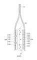
(第1實施形態)圖1係本發明之第1實施形態之附有帶之袋之俯視圖,圖2係圖1之II-II線剖視圖。如圖所示,附有帶之袋100包含:袋本體110,其具有藉由薄膜形成並相互對向之第1面111A及第2面111B;及帶120,其分別接合於袋本體110之第1面111A及第2面111B,並劃定形成於第1面111A與第2面111B之間之收納空間SP之一邊。(First Embodiment)Fig. 1 is a plan view of a bag with a belt in the first embodiment of the present invention, and Fig. 2 is a cross-sectional view taken along line II-II in Fig. 1. As shown in the figure, the belt-attached
袋本體110係例如由單層或多層之熱塑性樹脂薄膜形成。具體而言,熱塑性樹脂亦可為低密度聚乙烯(LDPE)、直鏈狀低密度聚乙烯(LLDPE)、或聚丙烯(PP)。PP亦可為均聚丙烯(HPP)、無規聚丙烯(RPP)、或嵌段聚丙烯(BPP)。於袋本體110由多層薄膜形成之情形時,於表基材亦可使用雙軸延伸聚丙烯(OPP)、雙軸延伸聚對苯二甲酸乙二酯(OPET)、或雙軸延伸尼龍(ONy)。該等不限定於源自化石燃料之樹脂,可為友善環境之生物塑料,亦可使用源自化石燃料之樹脂與生物塑料之混合物。作為生物塑料,較佳為例如生物聚乙烯。又,形成袋本體110之薄膜可包含鋁等金屬材料、或無機材料之層。藉由將袋本體110與稍後敘述之帶120或夾鏈帶220同樣由將聚乙烯作為主成分之樹脂組成物單材料化,而可實現再循環性優異且友善環境之構成。The
另,於本實施形態,藉由將2片薄膜重合,並於頂封部112、底封部113及側封部114相互接合而形成袋本體110,但於其他實施形態,亦可藉由將1片薄膜於與側封部114對應之部分折回而形成袋本體110。又,亦可於袋本體110,於與底封部113或側封部114對應之部分形成將薄膜向內側折入而得之部分,所謂角撐。於此情形時,角撐可藉由與第1面111A或第2面111B相同之薄膜形成,亦可藉由與其等不同之薄膜形成。又,附有夾鏈帶之袋100亦可為藉由於底部形成角撐而可豎立放置之自立袋。In addition, in this embodiment, the
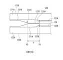
帶120如圖2所示,係剖面形狀包含相互對向之第1部分120A及第2部分120B之長條狀之構件。第1部分120A之剖面形狀包含第1厚壁部121A、第2厚壁部122A、薄壁部123A、123B及中間部124。第2部分120B之剖面形狀包含第1厚壁部121B、第2厚壁部122B及薄壁部123C。第1厚壁部121A、121B及第2厚壁部122A、122B可不為相同之厚度,但薄壁部123A、123B、123C(以下,有統稱為薄壁部123之情形)係形成為薄於第1厚壁部121A、121B及第2厚壁部122A、122B(以下,有統稱作為厚壁部121、122之情形)之任一者之部分。中間部124形成為厚於薄壁部123A、123B。中間部124與厚壁部121A、122A之厚度之大小關係不必限定,例如如圖示之例,中間部124與厚壁部121A、122A皆接合於第1面111A之情形時,較佳為中間部124由對應於厚壁部121A、122A之厚度形成。此處,對應之厚度意指不必為嚴密相同之厚度,而例如如圖示之例,為接近容易將厚壁部121A、122A與中間部124接合於同一面(第1面111A)之程度之厚度。具體而言,中間部124之厚度較佳為厚壁部121A、122A之±20%以內之厚度,更佳為±10%以內之厚度,進而更佳為相同之厚度。另,於厚壁部121A、122A之厚度不同之情形時,較佳為中間部124之厚度相對於其等厚度之平均值處於上述範圍內。藉由將中間部124之厚度設為如上所述之範圍,而可將中間部124更確實地接合於第1面111A。於後述之例中,關於形成於第2部分120B之中間部亦同樣。As shown in FIG. 2, the
第1部分120A於第1厚壁部121A及第2厚壁部122A處接合於袋本體110之第1面111A。第2部分120B亦於第1厚壁部121B及第2厚壁部122B處接合於袋本體110之第2面111B。圖示之例中,第1部分120A雖亦在中間部124處接合於第1面111A,但中間部124亦可未接合於第1面111A。另,基於製造時容易對位之觀點,將中間部124接合於第1面111A較為有利。又,第1厚壁部121A、121B及第2厚壁部122A、122B亦可不全面接合於第1面111A或第2面111B,而可在例如與薄壁部123A、123B、123C相鄰之部分未接合於第1面111A或第2面111B。於此情形時,可於厚壁部121、122與薄壁部123之間,設置厚壁部121、122與薄壁部123之中間厚度之部分。The
如上述之帶120藉由例如聚烯烴系樹脂之擠壓成形而形成。更具體而言,帶120亦可由低密度聚乙烯(LDPE)、直鏈狀低密度聚乙烯(LLDPE)、或聚丙烯(PP)形成。PP可為均聚丙烯(HPP)、無規聚丙烯(RPP)、或嵌段聚丙烯(BPP)。該等不限定於源自化石燃料之樹脂,亦可為友善環境之生物塑料,可使用源自化石燃料之樹脂與生物塑料之混合物。作為生物塑料,較佳為例如生物聚乙烯。於帶120之材料,亦可視需要,添加周知之添加劑,例如穩定劑、抗氧化劑、潤滑劑、抗帶電劑、或著色劑等。The
帶120亦可由將聚乙烯作為主成分之樹脂組成物單材料化。於此情形時,帶120之全體,即第1厚壁部121A、121B、第2厚壁部122A、122B、薄壁部123A、123B、123C、中間部124皆由將聚乙烯作為主成分之樹脂組成物形成。此處,主成分係樹脂組成物之佔據特定比例以上之成分,含有量通常為50質量%以上,較佳為70質量%以上,更佳為90質量%以上,進而佳為95質量%以上,尤佳為98質量%以上,最佳為100%之成分。但,即使於主成分之含有量為100%之情形時,亦允許混合添加劑或雜質。另,可藉由例如IR(Infrared:紅外線)法確認主成分。藉由以將聚乙烯作為主成分之樹脂組成物將帶120單材料化,而可實現再循環性優異且友善環境之構成。又,藉由使用生物聚乙烯作為聚乙烯,而可進而實現再循環性優異且友善環境之構成。The
此處,如圖2所示,於帶120之寬度方向規定第1區域R1、第2區域R2及第3區域R3。該等區域係於帶120之第1部分120A與第2部分120B相互對向之狀態下,各個部分共通之區域。第2區域R2位於第1區域R1與第3區域R3之間。另,第1區域R1、第2區域R2及第3區域R3可如圖2所示之例,於寬度方向上覆蓋帶120之全體,亦可如稍後敘述之其他例,未覆蓋帶120之全體。於第1部分120A,於第1區域R1及第3區域R3分別形成第1厚壁部121A及第2厚壁部122A,於第2區域R2之寬度方向之兩端部分別形成薄壁部123A及薄壁部123B,於薄壁部123A與薄壁部123B之間形成中間部124。另一方面,於第2部分120B,分別形成於第1區域R1及第3區域R3之第1厚壁部121B及第2厚壁部122B越過第2區域R2之寬度方向之端部而延伸。即,於第2區域120B,第1厚壁部121B及第2厚壁部122B分別自第1區域R1或第3區域R3跨及第2區域R2之一部分而形成。於第2部分120B,形成於第2區域R2之薄壁部123C與第1部分120A之中間部124對向。Here, as shown in FIG. 2, the first region R1 , the second region R2, and the third region R3 are defined in the width direction of the
如上所述,於本實施形態,於第1部分120A,薄壁部123A及薄壁部123B形成於第2區域R2之寬度方向之兩端部,對此,於第2部分120B,由於第1厚壁部121B及第2厚壁部122B分別越過第2區域R2之寬度方向之端部而延伸,故薄壁部123A、123B不與第2部分120B之薄壁部對向。形成於第2部分120B之薄壁部123C與第1部分120A之薄壁部123A、123B之間不對向,而與形成於薄壁部之間之中間部124對向。藉此,於第1部分120A與第2部分120B對向之情形時,薄壁部123A至薄壁部123C於帶120之寬度方向上交替,具體而言係自頂封部112側依序按薄壁部123A、薄壁部123C、及薄壁部123B之順序不重疊配置。As described above, in this embodiment, to the
藉由如上述之構成,於本實施形態之附有帶之袋100,例如使用者在帶120之長邊方向端部以形成於側封部114之凹槽115為起點撕裂袋本體110而開封之情形時,可使開封後之帶120及袋本體110之端部錯距。具體而言,例如如圖3A所示,於撕裂袋本體110之力F自第1面111A側作用之情形時,於帶120之第1部分120A薄壁部123A破斷,於第2部分120B薄壁部123C破斷,沿薄壁部123A、123C引導袋本體110之撕裂,藉此使開封後之帶120及袋本體110之端部錯距。如圖3B所示,於撕裂袋本體110之力F自第2面111B側作用之情形時,於帶120之第2部分120B薄壁部123C破斷,於第1部分120A薄壁部123B破斷,並沿薄壁部123B、123C引導袋本體110之撕裂,藉此使開封後之帶120及袋本體110之端部錯距。With the above-mentioned configuration, in the
根據本發明者等人之見解,相對於形成在撕裂袋本體110之力F作用之側(於圖3A之例為第1面111A側,於圖3B之例為第2面111B側)之薄壁部,形成於其相反側之薄壁部位於收納空間SP側之情形時,破斷後之帶120之端部容易錯距。因此,於例如上述之例,於帶120之第1部分120A未形成薄壁部123B之情形時,如圖3A所示之例,自第1面111A側作用力F之情形時,薄壁部123A與薄壁部123C破斷,藉此開封後之帶120之端部錯距,但如圖3B所示之例,自第2面111B側作用力F之情形時,因薄壁部123A位於較薄壁部123C更靠近頂封部112側,故第1部分120A並非於薄壁部123A而係於中間部124附近(另,於未形成薄壁部123B之情形時不稱為中間部)破斷,而開封後之帶120及袋本體110之端部可能未錯距。According to the findings of the inventors of the present invention, with respect to the side on which the force F formed on the
對此,於本實施形態,如上所述於自第1面111A側及第2面111B側之任一者作用力之情形時,相對於形成在力作用之側之薄壁部,形成於其相反側之薄壁部位於收納空間SP側之關係亦成立,故不論力作用之方向,皆可更確實地使開封後之帶120及袋本體110之端部錯距。藉此,如上所述,於自袋本體取出內容物時,容易於帶之端部插入手指等而擴大開口。此時,為了更容易地擴大開口,亦可於薄壁部以外之各部(厚壁部或中間部)之端部,形成面向袋本體之內側之肋部。In this regard, in this embodiment, when a force is applied from either the
另,於本實施形態中,薄壁部123A、123B、123C只要較相鄰之部分,即厚壁部121、122及中間部124薄壁即可,但為了容易藉由上述之力破斷,亦可以例如200 μm以下之厚度形成。薄壁部123A、123B、123C之厚度較佳為150 μm以下,更佳為120 μm以下,進而佳為100 μm以下,尤佳為80 μm以下。藉由將厚度設為此種範圍,而可降低撕裂強度,並可更容易使薄壁部破斷。薄壁部123A、123B、123C之厚度之下限值雖無特別限定,但通常為10 μm。In addition, in this embodiment, the thin-
另一方面,帶120之寬度方向之薄壁部123A、123B、123C之尺寸通常為10 μm以上,較佳為30 μm以上。上限通常為3 mm,較佳為1 mm以下。藉由設為該範圍,而利用例如於稍後敘述之例中與形成於缺口131之R(曲率半徑)之相互作用,提高開封性。On the other hand, the size of the thin-
另,於例如藉由擠壓成形而形成帶120之情形時,於厚壁部121、122或中間部124與薄壁部123A、123B、123C之間形成厚度過渡部。於此情形時,薄壁部123A、123B、123C作為較兩側之厚壁部121、122或中間部124中之薄者更為薄壁之部分而特定。因此,於兩側之厚壁部121、122及中間部124之厚度不同之情形時,可能於厚者與薄壁部123A、123B、123C之間存在既非厚壁部亦非中間部且非薄壁部之部分(厚度過渡部)。又,如上所述,於具體規定薄壁部123A、123B、123C之情形時,薄壁部123A、123B、123C作為滿足規定之厚度之部分而特定。於此情形時,可能於厚壁部121、122及中間部124之間分別存在既非厚壁部亦非中間部且非薄壁部之部分(厚度過渡部)。In addition, when the
另一方面,厚壁部121、122只要較相鄰之薄壁部123A、123B、123C厚壁即可,但厚度較佳為例如200 μm以上,更佳為250 μm以上,進而佳為300 μm以上。藉由將厚壁部121、122之厚度設為200 μm以上,撕裂強度變高,可防止因開封時之力致使厚壁部121、122破斷。又,厚壁部121、122之厚度之上限值雖無特別限定,但通常為700 μm。藉由將厚壁部121、122之厚度設為700 μm以下,而可防止因熔融扁平化而產生氣孔。On the other hand, the thick-walled parts 121 and 122 may be thicker than the adjacent thin-
又,如上所述,袋本體110藉由將2片薄膜重合,或將1片薄膜折回而形成,於將2片薄膜重合之情形時,藉由於形成第1面111A之薄膜與形成第2面111B之薄膜之間調整結晶配向之方向,而引導以凹槽115為起點之袋本體110之撕裂於第1面111A側與第2面111B側面向不同之方向,可容易使開封後之袋本體110之端部錯距。同樣地,於將1片薄膜折回之情形時,藉由調整第1面111A與第2面111B之間之折痕使之相對於薄膜之結晶配向之方向非平行且非直角,同樣可容易使開封後之袋本體110之端部錯距。In addition, as described above, the
圖4係用於對本發明之第1實施形態之帶之製造方法之例之進行說明之圖。亦如圖1所示,於本實施形態之附有帶之袋100,於帶120之長邊方向端部,形成與側封部114重疊之缺口131。該缺口131例如如圖4所示,於使用製袋機連續製造附有帶之袋100時形成。具體而言,於長條狀之帶120,以與製造後之袋本體110之寬度,即側封部114之間隔相同之間隔形成缺口131(於該時點為開口部)。之後,於袋本體110接合帶120,進而形成橫跨缺口131之側封部114、頂封部112及底封部113。藉由於側封部114之中央切斷接合有帶120之袋本體110,而獲得圖1所示之附有帶之袋100。Fig. 4 is a diagram for explaining an example of a method of manufacturing a belt according to the first embodiment of the present invention. As also shown in FIG. 1, in the belt-attached
如此形成之缺口131於例如使用者在帶120之長邊方向端部以形成於側封部114之凹槽115為起點欲撕裂袋本體110之情形時,引導以凹槽115為起點之袋本體110之撕裂沿形成於帶120之薄壁部行進。具體而言,例如如圖5A所示,於帶120之第1部分120A之側,可形成包含分別面向薄壁部123A、123B之兩股分叉之錐形部132A之形狀之缺口131A。又,如圖5B所示,亦可於帶120之第2部分120B之側,形成包含面向薄壁部123C之單一之錐形部132B之形狀之缺口131B。如此,藉由以對準分別形成於帶120之第1部分120A及第2部分120B之薄壁部之位置之形狀形成缺口131,而如上所述,可更容易且確實地獲得使開封後之帶120及袋本體110之端部錯距之效果。又,較佳為錐形部之前端附加R(曲率半徑)。藉由附加R,即使於加工時於銳角之前端位置產生些許偏移,亦可朝薄壁部引導撕裂,可減少製造不良品之數量。作為R,例如為0.1 mm~1.0 mm,較佳為0.2 mm~0.7 mm。The
圖6係顯示本發明之第1實施形態之帶之例之剖視圖。於上述參照圖1及圖2說明之例中,在安裝於袋本體110之前,獨立供給要安裝於袋本體110之帶120。於此情形時,可以第1部分120A與第2部分120B於任意位置連結之狀態供給。例如如圖所示,可以第1部分120A與第2部分120B將圖2所示之第3區域R3之與第2區域R2為相反側之寛度方向端部,即第2厚壁部122A、122B之間連結之狀態供給。或,亦可以第1部分120A與第2部分120B將圖2所示之第1區域R1之與第2區域R2為相反側之寛度方向端部,即第1厚壁部121A、121B之間連結之狀態供給。於此情形時,可藉由將連結部分分離、或彎曲,而使帶120之第1部分120A與第2部分120B對向。即,本實施形態之帶120不必於供給之時點將第1部分120A與第2部分120B對向,而只要以可使第1部分120A與第2部分120B對向之方式構成即可。Fig. 6 is a cross-sectional view showing an example of a belt in the first embodiment of the present invention. In the example described above with reference to FIGS. 1 and 2, before being installed in the
於上述之例中,雖帶120之第1部分120A與第2部分120B之間之連結部分最終分離,但分離連結部分之步驟可於將帶120安裝於袋本體110之前進行,或亦可於將帶120安裝於袋本體110之後進行。於後者之情形時,於將帶120安裝於袋本體110之時點,藉由於連結部分將帶120彎曲而使第1部分120A與第2部分120B對向。於此情形時,可使第1部分120A與第2部分120B於位置關係固定之狀態相互對向。例如藉由維持第1部分120A與第2部分120B連結之狀態直至形成上述之缺口131為止,而可減少第1部分120A與第2部分120B之間之缺口131之位置偏移。In the above example, although the connecting part between the
圖7及圖8係顯示第1實施形態之變化例之剖視圖。於上述參照圖2等說明之例,於帶120中,第1部分120A中,分別於第1區域R1及第3區域R3形成第1厚壁部121A及第2厚壁部122A,分別於第2區域R2之兩端部形成薄壁部123A、123B,並於薄壁部123A、123B之間形成中間部124。又,於第2部分120B,分別形成於第1區域R1及第3區域R3之第1厚壁部121B及第2厚壁部122B越過第2區域R2之端部而延伸,並形成與第1部分120A之中間部124對向之薄壁部123C。Fig. 7 and Fig. 8 are cross-sectional views showing a modification of the first embodiment. In the example described above with reference to FIG. 2 and the like, in the
對此,於圖7之例,於第1部分120A,分別於第1區域R1及第3區域R3形成第1厚壁部121A及第2厚壁部122A,分別於第2區域R2之兩端部形成薄壁部123A、123B。但,於圖7之例,於薄壁部123A、123B之間形成2個中間部124A、124B,於中間部124A、124B之間形成其他薄壁部123D。另一方面,於圖7之例,第2部分120B中,分別形成於第1區域R1及第3區域R3之第1厚壁部121B及第2厚壁部122B越過第2區域R2之端部而延伸。但,於圖7之例,於第2區域R2之兩端以外之部分形成2個薄壁部123C、123E。薄壁部123C、123E分別與第1部分120A之中間部124A、124B對向。即,於本實施形態中,與第1部分120A之中間部對向之第2部分120B之薄壁部不限定於1個亦可為複數個。於此情形時,由於形成於第1部分120A之薄壁部與形成於第2部分120B之薄壁部未對向,故與圖2之例同樣,不論力作用之方向,皆可使開封後之帶120之端部錯距。In this regard, in the embodiment of FIG. 7, in the
另一方面,圖8之例中,於第1部分120A,分別於第1區域R1及第3區域R3形成第1厚壁部121A及第2厚壁部122A,分別於第2區域R2之兩端部形成薄壁部123A、123B。但,圖8之例中,於薄壁部123A、123B之間形成2個中間部124A、124B,於中間部124A、124B之間形成其他薄壁部123D。作為與圖7之例之不同點,於圖8之例中,薄壁部123D形成於偏向薄壁部123B側之位置,而非薄壁部123A、123B之中間。因此,中間部124A之寛度寬於中間部125B。另一方面,圖8之例中,第2部分120B與圖2之例同樣地形成,包含第1厚壁部121B、第2厚壁部122B、及薄壁部123C。薄壁部123C與第1部分120A之中間部124A對向。於此情形時,由於形成於第1部分120A之薄壁部與形成於第2部分120B之薄壁部未對向,故與圖2之例同樣地,不論力作用之方向為何,皆可使開封後之帶120之端部錯距。On the other hand, in the example of FIG. 8, in the
圖9係顯示第1實施形態之其他變化例之剖視圖。圖9所示之例中,規定在帶120之寛度方向之第1區域R1、第2區域R2及第3區域R3未覆蓋帶120全體。於圖示之例中,分別於厚壁部121A、121B側之帶120之端部形成薄壁部127A、127B,於厚壁部122A、122B側之帶120之端部形成薄壁部127C、127D。該等薄壁部127與上述之薄壁部123不同,未意圖於將附有帶之袋100開封時破斷。具體而言,例如薄壁部127亦可形成為厚於薄壁部123,或即使將薄壁部127與薄壁部123以相同之方式形成為薄壁,但只要如上述參照圖5A及圖5B說明之缺口131之錐形部朝向薄壁部123,而未朝向薄壁部127,則於將附有帶之袋100開封時薄壁部127不會破斷。於此情形時,將第1區域R1規定為形成有厚壁部121A及厚壁部121B之區域(不包含薄壁部127A、127B)。同樣地,將第3區域R3規定為形成有厚壁部122A及厚壁部122B之區域(不包含厚壁部127C、127D)之區域。於圖示之例中,薄壁部127A~127D、及較其更靠近帶120之寛度方向端部側之區域不包含於第1區域R1、第2區域R2及第3區域R3之任一者。Fig. 9 is a cross-sectional view showing another modification of the first embodiment. In the example shown in FIG. 9, the first region R1 , the second region R2, and the third region R3 in the width direction of the
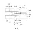
(第2實施形態)圖10係本發明之第2實施形態之附有夾鏈帶之袋之俯視圖,圖11係圖10之XI-XI線剖視圖。如圖所示,附有夾鏈帶之袋200包含:與上述第1實施形態同樣之袋本體110;及夾鏈帶220,其分別接合於袋本體110之第1面111A及第2面111B,並劃定形成於第1面111A與第2面111B之間之收納空間SP之一邊。(Second Embodiment)Fig. 10 is a plan view of a bag with a zipper tape in the second embodiment of the present invention, and Fig. 11 is a cross-sectional view taken along the line XI-XI in Fig. 10. As shown in the figure, the
夾鏈帶220如圖11所示,係剖面形狀包含相互對向之第1部分220A及第2部分220B之長條狀之構件。第1部分220A及第2部分220B各者之剖面形狀包含與第1實施形態同樣之第1厚壁部121A、121B、第2厚壁部122A、122B、薄壁部123A、123B、123C及中間部124、構成夾鏈部分之基部條片225A、225B及卡合部226A、226B。基部條片225A、225B分別接合於袋本體110之第1面111A及第2面111B而相互對向,卡合部226A、226B分別自基部條片225A、225B突出並可相互卡合。As shown in FIG. 11, the
於本實施形態中,夾鏈帶220之第2厚壁部122A、122B分別與基部條片225A、225B連續。夾鏈帶220之寛度方向之第1區域R1、第2區域R2、及第3區域R3如下規定:第3區域R3與基部條片225A、225B之夾鏈區域相鄰,且第2區域R2位於第1區域R1與第3區域R3之間。另,第1區域R1、第2區域R2及第3區域R3可如圖11所示之例,於寛度方向上覆蓋夾鏈帶220之基部條片225A、225B及卡合部226A、226B以外之區域之全體,亦可如稍後之其他例,未覆蓋該區域。於圖示之例中,第2厚壁部122A、122B形成為厚於基部條片225A、225B,於其他之例第2厚壁部122A、122B與基部條片225A、225B可為相同之厚度。另,卡合部226A、226B之形狀不限定於圖示之例,可採用組合爪狀、鉤狀、或瘤狀等周知之各種夾鏈之卡合部之形狀。於圖示之例,雖卡合部226A為公模,卡合部226B為母模,但亦可相反。又,於圖示之例,雖配置1對卡合部,但亦可配置複數對卡合部。夾鏈帶220與第1實施形態之帶120同樣,藉由例如聚烯烴系樹脂之擠壓成形而形成,亦可視需要,於材料添加周知之添加劑,例如穩定劑、抗氧化劑、潤滑劑、抗帶電劑、或著色劑等。又,夾鏈帶220之材料不限定於源自化石燃料之樹脂,可為友善環境之生物塑料,亦可使用源自化石燃料之樹脂與生物塑料之混合物。作為生物塑料,較佳為例如生物聚乙烯。In this embodiment, the second
又,夾鏈帶220與上述之帶120同樣,亦可以將聚乙烯作為主成分之樹脂組成物單材料化。於此情形時,夾鏈帶220之全體由將聚乙烯作為主成分之樹脂組成物形成。藉由以將聚乙烯作為主成分之樹脂組成物將夾鏈帶220單材料化,而可實現再循環性優異且友善環境之構成。又,藉由使用生物聚乙烯作為聚乙烯,而可進而實現再循環性優異且友善環境之構成。In addition, the
此處,於本實施形態,亦如圖11所示,於夾鏈帶220之寛度方向規定第1區域R1、第2區域R2、及第3區域R3。該等區域係於夾鏈帶220之第1部分220A與第2部分220B相互對向之狀態下,各個部分共通之區域。第2區域R2位於第1區域R1與第3區域R3之間。於第1部分220A,分別於第1區域R1及第3區域R3形成第1厚壁部121A及第2厚壁部122A,分別於第2區域R2之寛度方向之兩端部形成薄壁部123A及薄壁部123B,於薄壁部123A與薄壁部123B之間形成中間部124。另一方面,於第2部分220B,分別形成於第1區域R1及第3區域R3之第1厚壁部121B及第2厚壁部122B越過第2區域R2之寛度方向之端部而延伸。即,於第2部分220B,第1厚壁部121B及第2厚壁部122B分別自第1區域R1或第3區域R3跨及第2區域R2之一部分而形成。於第2部分220B,形成於第2區域R2之薄壁部123C與第1部分220A之中間部124對向。藉此,於本實施形態之附有夾鏈帶之袋200,亦與第1實施形態之附有帶之袋100同樣,例如使用者在帶120之長邊方向端部以形成於側封部114之凹槽115為起點撕裂袋本體110而開封之情形時,可使開封後之夾鏈帶220及袋本體110之端部錯距。Here, also in this embodiment, as shown in FIG. 11, the first region R1 , the second region R2 , and the third region R3 are defined in the width direction of the
圖12係顯示本發明之第2實施形態之夾鏈帶之例之剖視圖。於上述參照圖10及圖11說明之例中,在安裝於袋本體110之前,獨立供給要安裝於袋本體110之夾鏈帶220。可以第1部分220A與第2部分220B於任意位置連結之狀態供給。例如於此情形時,如圖所示,可以第1部分220A與第2部分220B將例如基部條片225A、225B之與第3區域R3為相反側之寛度方向端部之間連結之狀態供給。或,亦可於第1部分220A與第2部分220B將圖11所示之第1區域R1之與第2區域R2為相反側之寛度方向端部,即第1厚壁部121A、121B之間連結之狀態供給。於此情形時,藉由將連結部分分離、或彎曲,而可使夾鏈帶220之第1部分220A與第2部分220B對向。即,本實施形態之夾鏈帶220,可不必於供給之時點將第1部分220A與第2部分220B對向,而只要以可使第1部分220A與第2部分220B對向之方式構成即可。Fig. 12 is a cross-sectional view showing an example of the zipper belt of the second embodiment of the present invention. In the example described above with reference to FIGS. 10 and 11, before being installed in the
於上述例中,雖夾鏈帶220之第1部分220A與第2部分220B之間之連結部分最終分離,但分離連結部並使卡合部226A、226B相互卡合之步驟可於將夾鏈帶220安裝於袋本體110之前進行,或亦可於將夾鏈帶220安裝於袋本體110之後進行。於後者之情形時,於將夾鏈帶220安裝於袋本體110之時點,藉由將夾鏈帶220於連結部分彎曲而使第1部分220A與第2部分220B對向。於此情形時,可使第1部分220A與第2部分220B於位置關係固定之狀態相互對向。例如,將上述參照圖4等說明之缺口131亦形成於夾鏈帶220之情形時,藉由維持第1部分220A與第2部分220B連結之狀態直至形成缺口131為止,而可減少第1部分220A與第2部分220B之間之缺口131之位置偏移。In the above example, although the connecting part between the
圖13係顯示第2實施形態之其他變化例之剖視圖。於圖13所示之例,第1區域R1、第2區域R2及第3區域R3未覆蓋夾鏈帶220之基部條片225A、225B及卡合部226A、226B以外之區域之全體。於圖示之例,分別於厚壁部121A、121B側之夾鏈帶220之端部形成薄壁部127A、127B,於厚壁部122A、122B與基部條片225A、225B之間形成薄壁部227C、227D。薄壁部227亦與薄壁部127同樣,未意圖於開封附有夾鏈帶之袋200時破斷。於此種情形時,規定第1區域R1為形成厚壁部121A及厚壁部121B之區域(不包含薄壁部127A、127B)。同樣地,規定第3區域R3為形成厚壁部122A及厚壁部122B之區域(不包含薄壁部227C、227D)。於圖示之例中,薄壁部127A、127B及較其更靠近夾鏈帶220之寛度方向端部側之區域、及薄壁部227C、227D至基部條片225A、225B之間之區域亦不包含於第1區域R1、第2區域R2及第3區域R3之任一者。Fig. 13 is a cross-sectional view showing another modification of the second embodiment. In the example shown in FIG. 13, the first region R1 , the second region R2 and the third region R3 do not cover the entire area other than the base strips 225A, 225B and the engaging
圖14係顯示本發明之實施形態之缺口之其他例之圖。圖14所示之缺口之形狀亦可應用於例如上述第1及第2實施形態之任一者。具體而言,於圖14所示之例,與側封部114(未圖示)重疊而於帶120之長邊方向端部形成缺口231A、231B。缺口231A形成於帶120之第1部分120A之側,並包含面向薄壁部123A、123B之膨出部232A、232B。另一方面,缺口231B形成於帶120之第2部分120B之側,並包含面向薄壁部123C之錐形部232C。藉由此種缺口231A、231B,與上述參照圖5A及圖5B說明之例同樣,例如使用者以帶120之長邊方向端部為起點欲撕裂袋本體之情形時,可引導袋本體之撕裂沿形成於帶120之薄壁部行進。於其他之例,如圖15所示,膨出部232A、232B之中間部亦可為不具有曲率之形狀。Fig. 14 is a diagram showing another example of the notch in the embodiment of the present invention. The shape of the notch shown in FIG. 14 can also be applied to any of the above-mentioned first and second embodiments, for example. Specifically, in the example shown in FIG. 14,
此處,於本說明書中,錐形部在缺口之寛度方向兩側之邊緣為直線狀,且該等直線係形成向薄壁部逐漸變窄之錐形之部分。另一方面,膨出部係缺口之形狀向薄壁部伸出之部分。如圖14所示之例,可於錐形部之前端附加R(曲率半徑)。如上已述,藉由於缺口之形狀附加R,即使加工時於缺口之位置產生些許偏差,亦可朝薄壁部引導撕裂,並可減少製造不良品之數量。於在錐形部之前端附加R之情形時,錐形部與膨出部在包含向薄壁部附加R之部分之點共通。若於附加R之部分之兩側有形成錐形之直線狀之邊緣則為錐形部,附加R之部分之兩側為曲線狀之邊緣、或即使為直線狀但未形成錐形之情形時,皆變為膨出部。例如,於上述圖14之例中,錐形部232C亦可作為膨出部形成。Here, in this specification, the edges of the tapered portion on both sides of the width direction of the notch are linear, and the straight lines form a tapered portion that gradually narrows toward the thin-walled portion. On the other hand, the bulging part is the part where the shape of the notch extends toward the thin-walled part. In the example shown in Fig. 14, R (radius of curvature) can be added to the front end of the tapered portion. As mentioned above, by adding R to the shape of the notch, even if a slight deviation occurs in the position of the notch during processing, tearing can be guided toward the thin-walled portion, and the number of defective products can be reduced. When R is added to the front end of the tapered portion, the tapered portion and the bulging portion are common in that they include the portion where R is added to the thin-walled portion. If there is a tapered straight edge on both sides of the R-added part, it is a tapered part, and the R-added part has curved edges on both sides, or when it is straight but not tapered. , All become bulging parts. For example, in the example of FIG. 14 described above, the tapered
於錐形部之前端之情形時,與已述之例同樣,作為R,例如為0.1 mm~1.0 mm,較佳為0.2 mm~0.7 mm。膨出部之情形時,作為R,例如為0.1 mm~2.0 mm,較佳為0.1~1.5 mm,更佳為0.1 mm~1.0 mm,進而佳為0.2 mm~0.8 mm,尤佳為0.2 mm~0.7 mm。In the case of the front end of the tapered portion, as in the above-mentioned example, R is, for example, 0.1 mm to 1.0 mm, preferably 0.2 mm to 0.7 mm. In the case of a bulging part, R is, for example, 0.1 mm to 2.0 mm, preferably 0.1 to 1.5 mm, more preferably 0.1 mm to 1.0 mm, still more preferably 0.2 mm to 0.8 mm, particularly preferably 0.2 mm to 0.7 mm.
又,於圖14所示之例,帶120之長邊方向上,缺口231A之膨出部232A、232B連接於薄壁部123A、123B之第1位置P1、與缺口231B之錐形部232C連接於薄壁部123C之第2位置P2不同。更具體而言,於圖示之例中,第2位置P2較第1位置P1更接近帶120之長邊方向端部。藉由此種構成,自錐形部232C開始撕裂薄壁部123C之時序、與自膨出部232A、232B開始撕裂薄壁部123A、123B之時序錯開,而可選擇性撕裂薄壁部123A、123B中阻力較小側之薄壁部。與上述參照圖5A及圖5B說明之例同樣,缺口131A之兩股分叉之錐形部132A與薄壁部123A、123B相接之位置、及缺口131B之錐形部132B與薄壁部123C連接之位置亦可不同。帶120之長邊方向上,第1位置P1與第2位置P2之間之距離較佳為1 mm以上。In the example shown in FIG. 14, in the longitudinal direction of the
圖16係顯示本發明之實施形態之缺口之進而其他例之圖。圖16所示之缺口之形狀亦可應用於例如上述第1及第2實施形態之任一者。於圖16所示之例,亦與側封部114(未圖示)重疊而於帶120之長邊方向端部形成缺口231A、231B。作為與上述圖14所示之例之不同點,於圖16之例,缺口231A所包含之膨出部232A、232B中之膨出部232A較膨出部232B更向帶120之長邊方向中央大幅膨出。藉此,膨出部232A、232B之間之中間部233與圖14之例不同,於帶120之寛度方向上為非對稱之形狀。具體而言,中間部233於膨出部232B至膨出部232A,相對於帶120之寛度方向傾斜。作為該結果,中間部233於帶120之第1部分120A與第2部分120B重合時,不與第2部分120B之薄壁部123C正交,而傾斜相交。藉此,例如不僅於袋本體之撕裂如圖16所示之箭頭Q1般向膨出部232A行進之情形,如箭頭Q2般向膨出部232A、232B之中間行進之情形時,亦可朝膨出部232A、及緊接於膨出部232A之薄壁部123A引導撕裂。Fig. 16 is a diagram showing another example of the notch in the embodiment of the present invention. The shape of the notch shown in FIG. 16 can also be applied to any of the above-mentioned first and second embodiments, for example. In the example shown in FIG. 16, the side seal 114 (not shown) is also overlapped, and
圖17亦係顯示本發明之實施形態之缺口之進而其他例之圖。於圖17所示之例,與側封部114(未圖示)重疊而於帶120之長邊方向端部形成缺口231A、231B。作為與上述圖14所示之例之不同點,於圖17之例,於帶120之第1部分120A之缺口231A形成面向薄壁部123A之錐形部232D,自第2厚壁部122A側向錐形部232D形成2條斜邊α、β。此處,斜邊意為缺口單側之邊緣相對於帶120之長邊方向及寛度方向之兩者傾斜之部分。雖於圖示之例形成2條斜邊α、β,但亦可形成1條斜邊、或3條以上之斜邊。或,與由斜邊α、β形成之彎曲部同樣,形成向外側伸出之彎曲部。該等斜邊或彎曲部於帶120之第1部分120A與第2部分120B重合時,橫跨第2部分120B之薄壁部123C。藉此,與上述圖16之例同樣,例如不僅於袋本體之撕裂如箭頭Q1般向錐形部232D行進之情形,如箭頭Q2般與錐形部232D偏移而行進之情形時,亦可朝錐形部232D、及緊接於錐形部232D之薄壁部123A引導撕裂。Fig. 17 is also a diagram showing another example of the notch in the embodiment of the present invention. In the example shown in FIG. 17, it overlaps with the side seal part 114 (not shown), and the
另,於上述參照圖16及圖17說明之例,雖朝接近頂封部112側之薄壁部123A引導袋本體之撕裂,但亦可與此相反,朝距頂封部112較遠之側之薄壁部123B引導撕裂。具體而言,關於圖16之例,膨出部232B可較膨出部232A更向帶120之長邊方向中央大幅膨出。又,關於圖17之例,亦可向薄壁部123B形成錐形部232D。In addition, in the example described above with reference to FIG. 16 and FIG. 17, although the tearing of the bag body is guided toward the thin-
此處,關於上述參照圖14至圖17說明之例,帶120之第1部分120A中膨出部232A或錐形部232D連接於薄壁部123A之第1位置P1、與第2部分120B中錐形部232C或膨出部連接於薄壁部123C之第2位置P2不同,且第2位置P2較第1位置P1更接近帶120之長邊方向端部。第1位置P1與第2位置P2之間之距離d較佳為2 mm以上,更佳為4 mm以上,進而佳為8 mm以上。上限值較佳為50 mm以下,更佳為30 mm以下,進而佳為20 mm以下。Here, regarding the example described above with reference to FIGS. 14 to 17, the bulging
另,上述第1實施形態說明之關於厚壁部121、122及薄壁部123之厚度等之構成於第2實施形態亦同樣。又,上述對第1實施形態說明之變化例亦皆可應用於第2實施形態。於上述說明之實施形態中,帶及夾鏈帶之第1及第2部分雖以大致相同之寛度形成並全面對向,但於其他實施形態中,帶或夾鏈帶之第1及第2部分之任一者之寛度亦可寬於另一者,藉此以第1部分與第2部分局部對向之方式構成。In addition, the structure of the thickness of the thick-walled parts 121, 122 and the thin-
又,上述中已對容器本體為袋狀之袋本體之例進行說明,但亦可於袋狀以外之容器本體接合帶或夾鏈帶而提供附有帶之容器或附有夾鏈帶之容器。又,上述中已對第1厚壁部、第2厚壁部、薄壁部及中間部連續形成之例進行說明,但例如不僅厚壁部及中間部接合於容器本體之面,亦將薄壁部接合於容器本體之面之情形時,亦可使薄壁部與第1厚壁部、第2厚壁部或中間部之間至少於1處分離,而作為複數個長條狀之構件之組合提供帶或夾鏈帶。In addition, the example of the bag body with the container body in the shape of a bag has been described above, but it is also possible to provide a container with a belt or a container with a chain belt by joining a belt or a zipper belt to the container body other than the bag shape. . In addition, in the above, the example in which the first thick portion, the second thick portion, the thin portion, and the intermediate portion are continuously formed has been described. However, for example, not only the thick portion and the intermediate portion are joined to the surface of the container body, but also the thin When the wall portion is joined to the surface of the container body, the thin-walled portion can be separated from the first thick-walled portion, the second thick-walled portion, or the middle portion at least at one place, and used as a plurality of elongated members The combination provides belt or clip chain belt.
以上,已一面參照附加圖式一面對本發明之較佳實施形態詳細地進行說明,但本發明不限於該等例。若為本發明所屬之技術領域之業者,當明瞭在專利請求範圍所記載之技術性思想範疇內,可想到各種變更例或修正例,應了解該等當然亦為屬於本發明之技術範圍內者。Above, the preferred embodiments of the present invention have been described in detail with reference to the attached drawings, but the present invention is not limited to these examples. If you are a person in the technical field to which the present invention belongs, it should be understood that within the scope of the technical ideas recorded in the scope of the patent claim, various modifications or amendments can be conceived, and it should be understood that these are of course also within the technical scope of the present invention .
100:袋110:袋本體111A:第1面111B:第2面112:頂封部113:底封部114:側封部115:凹槽120:帶120A:第1部分120B:第2部分121A:第1厚壁部121B:第1厚壁部122A:第2厚壁部122B:第2厚壁部123A:薄壁部123B:薄壁部123C:薄壁部123D:薄壁部123E:薄壁部124:中間部124A:中間部124B:中間部127A:薄壁部127B:薄壁部127C:薄壁部127D:薄壁部131:缺口131A:缺口131B:缺口132A:錐形部132B:錐形部200:袋220:夾鏈帶220A:第1部分220B:第2部分225A:基部條片225B:基部條片226A:卡合部226B:卡合部227C:薄壁部227D:薄壁部231A:缺口231B:缺口232A:膨出部232B:膨出部232C:錐形部232D:錐形部233:中間部d:距離F:力P1:第1位置P2:第2位置Q1:箭頭Q2:箭頭R1:第1區域R2:第2區域R3:第3區域SP:收納空間α:斜邊β:斜邊100: bag 110:
圖1係本發明之第1實施形態之附有帶之袋之俯視圖。圖2係圖1之II-II線剖視圖。圖3A係顯示於圖1之例中自第1面側作用力之情形之圖。圖3B係顯示於圖1之例中自第2面側作用力之情形之圖。圖4係用於對本發明之第1實施形態之帶之製造方法之例進行說明之圖。圖5A係顯示圖4所示之例之缺口之形狀之例之圖。圖5B係顯示圖4所示之例之缺口之形狀之例之圖。圖6係顯示本發明之第1實施形態之帶之例之剖視圖。圖7係顯示第1實施形態之變化例之剖視圖。圖8係顯示第1實施形態之變化例之剖視圖。圖9係顯示第1實施形態之其他變化例之剖視圖。圖10係本發明之第2實施形態之附有夾鏈帶之袋之俯視圖。圖11係圖10之XI-XI線剖視圖。圖12係顯示本發明之第2實施形態之夾鏈帶之例之剖視圖。圖13係顯示第2實施形態之其他變化例之剖視圖。圖14係顯示本發明之實施形態之缺口之其他例之圖。圖15係顯示本發明之實施形態之缺口之其他例之圖。圖16係顯示本發明之實施形態之缺口之其他例之圖。圖17係顯示本發明之實施形態之缺口之其他例之圖。Fig. 1 is a plan view of a bag with a belt in the first embodiment of the present invention.Fig. 2 is a cross-sectional view taken along line II-II of Fig. 1;Fig. 3A is a diagram showing a situation where a force is applied from the first surface side in the example of Fig. 1.Fig. 3B is a diagram showing a situation where a force is applied from the second surface side in the example of Fig. 1.Fig. 4 is a diagram for explaining an example of a method of manufacturing a belt according to the first embodiment of the present invention.FIG. 5A is a diagram showing an example of the shape of the notch in the example shown in FIG. 4. FIG.FIG. 5B is a diagram showing an example of the shape of the notch in the example shown in FIG. 4. FIG.Fig. 6 is a cross-sectional view showing an example of a belt in the first embodiment of the present invention.Fig. 7 is a cross-sectional view showing a modification of the first embodiment.Fig. 8 is a cross-sectional view showing a modification of the first embodiment.Fig. 9 is a cross-sectional view showing another modification of the first embodiment.Fig. 10 is a plan view of a bag with a zipper tape in the second embodiment of the present invention.Fig. 11 is a cross-sectional view taken along line XI-XI of Fig. 10;Fig. 12 is a cross-sectional view showing an example of the zipper belt of the second embodiment of the present invention.Fig. 13 is a cross-sectional view showing another modification of the second embodiment.Fig. 14 is a diagram showing another example of the notch in the embodiment of the present invention.Fig. 15 is a diagram showing another example of the notch in the embodiment of the present invention.Fig. 16 is a diagram showing another example of the notch in the embodiment of the present invention.Fig. 17 is a diagram showing another example of the notch in the embodiment of the present invention.
111A:第1面111A:
111B:第2面111B: Side 2
112:頂封部112: Top Seal
120:帶120: belt
120A:第1部分120A:
120B:第2部分120B: Part 2
121A:第1厚壁部121A: 1st thick wall part
121B:第1厚壁部121B: 1st thick wall part
122A:第2厚壁部122A: 2nd thick wall part
122B:第2厚壁部122B: 2nd thick wall part
123A:薄壁部123A: Thin-walled part
123B:薄壁部123B: Thin-walled part
123C:薄壁部123C: Thin-walled part
124:中間部124: middle part
R1:第1區域R1 :
R2:第2區域R2 : Zone 2
R3:第3區域R3 : Zone 3
SP:收納空間SP: storage space
Claims (23)
Translated fromChineseApplications Claiming Priority (6)
| Application Number | Priority Date | Filing Date | Title |
|---|---|---|---|
| JP2019177128 | 2019-09-27 | ||
| JP2019-177128 | 2019-09-27 | ||
| JP2020005889 | 2020-01-17 | ||
| JP2020-005889 | 2020-01-17 | ||
| JP2020-046759 | 2020-03-17 | ||
| JP2020046759 | 2020-03-17 |
Publications (2)
| Publication Number | Publication Date |
|---|---|
| TW202122005Atrue TW202122005A (en) | 2021-06-16 |
| TWI855166B TWI855166B (en) | 2024-09-11 |
Family
ID=75165837
Family Applications (1)
| Application Number | Title | Priority Date | Filing Date |
|---|---|---|---|
| TW109133306ATWI855166B (en) | 2019-09-27 | 2020-09-25 | Belt, zipper belt, container with belt and manufacturing method thereof |
Country Status (6)
| Country | Link |
|---|---|
| US (2) | US11882908B2 (en) |
| JP (2) | JPWO2021060235A1 (en) |
| KR (1) | KR102842858B1 (en) |
| CN (2) | CN118770746A (en) |
| TW (1) | TWI855166B (en) |
| WO (1) | WO2021060235A1 (en) |
Families Citing this family (2)
| Publication number | Priority date | Publication date | Assignee | Title |
|---|---|---|---|---|
| CN118770746A (en)* | 2019-09-27 | 2024-10-15 | 出光统一科技株式会社 | Belt, clip belt, container with belt and manufacturing method thereof |
| US20230143914A1 (en)* | 2021-11-08 | 2023-05-11 | Peel Plastic Products Limited | Bag with tear line and notch |
Family Cites Families (27)
| Publication number | Priority date | Publication date | Assignee | Title |
|---|---|---|---|---|
| JPH07121747B2 (en)* | 1986-10-03 | 1995-12-25 | トタニ技研工業株式会社 | Plastic bag |
| US5664303A (en) | 1995-11-06 | 1997-09-09 | Illinois Tool Works Inc. | Differential flange header package |
| JP5197921B2 (en)* | 2006-03-17 | 2013-05-15 | 株式会社生産日本社 | Plastic bag body |
| JP4994138B2 (en)* | 2007-07-18 | 2012-08-08 | 株式会社生産日本社 | Bag opening tape and packaging bag |
| JP5202999B2 (en)* | 2008-03-12 | 2013-06-05 | 株式会社生産日本社 | Plastic bag body |
| JP5638278B2 (en)* | 2009-10-19 | 2014-12-10 | 出光ユニテック株式会社 | Easy tear zipper tape and packaging bag with easy tear zipper tape |
| JP5595026B2 (en)* | 2009-12-11 | 2014-09-24 | 出光ユニテック株式会社 | Zipper tape and packaging bag with zipper tape |
| JP5756268B2 (en)* | 2010-09-10 | 2015-07-29 | 出光ユニテック株式会社 | Manufacturing method of packaging bag with zipper tape, packaging bag with zipper tape, and manufacturing device of packaging bag with zipper tape |
| JP5561107B2 (en)* | 2010-11-04 | 2014-07-30 | 大日本印刷株式会社 | Packaging bag |
| JP5694852B2 (en)* | 2011-05-31 | 2015-04-01 | 出光ユニテック株式会社 | Zipper tape heat sealing method, zipper tape film roll manufacturing method, and zipper tape packaging bag manufacturing method |
| JP2013112356A (en)* | 2011-11-28 | 2013-06-10 | Meiwa Pax Co Ltd | Easy-peel easy-opening packaging bag and package |
| JP6041494B2 (en)* | 2012-01-23 | 2016-12-07 | 出光ユニテック株式会社 | Cut tape, zipper tape, and packaging bag |
| JP5958214B2 (en)* | 2012-09-12 | 2016-07-27 | 凸版印刷株式会社 | Packaging bag |
| JP6087560B2 (en)* | 2012-09-28 | 2017-03-01 | 富士特殊紙業株式会社 | Pillow packaging bag with zipper |
| JP5512847B1 (en)* | 2013-03-01 | 2014-06-04 | 東タイ株式会社 | Soft film packaging bag |
| JP6288407B2 (en)* | 2013-05-09 | 2018-03-07 | 東洋製罐株式会社 | Easy-open packaging bag |
| JP6259351B2 (en)* | 2014-04-10 | 2018-01-10 | 株式会社生産日本社 | Packaging bag and manufacturing method thereof |
| KR20140138559A (en)* | 2014-10-27 | 2014-12-04 | 주식회사 블리스팩 | A laminate film having the line type cutting feature and a package produced by using the same |
| US10450106B2 (en) | 2015-03-31 | 2019-10-22 | Idemitsu Unitech Co., Ltd. | Bag with zipper tape and method for producing same |
| JP7037266B2 (en)* | 2015-09-25 | 2022-03-16 | 出光ユニテック株式会社 | Bag with zipper tape |
| JP6656878B2 (en)* | 2015-10-23 | 2020-03-04 | 株式会社細川洋行 | Packaging bag and manufacturing method of packaging bag |
| JP7115855B2 (en) | 2016-01-07 | 2022-08-09 | 出光ユニテック株式会社 | Bag and method for manufacturing bag |
| JP6087014B1 (en)* | 2016-06-24 | 2017-03-01 | 丸東産業株式会社 | Packaging bag |
| JP2019137440A (en)* | 2018-02-13 | 2019-08-22 | 株式会社細川洋行 | Bag with zipper |
| JP7561743B2 (en)* | 2019-09-20 | 2024-10-04 | 出光ユニテック株式会社 | Tape, zipper tape, container with tape and container with zipper tape |
| CN118770746A (en)* | 2019-09-27 | 2024-10-15 | 出光统一科技株式会社 | Belt, clip belt, container with belt and manufacturing method thereof |
| JP2021080016A (en)* | 2019-11-22 | 2021-05-27 | 出光ユニテック株式会社 | Container with tape, method for producing container with tape, and tape |
- 2020
- 2020-09-23CNCN202410998786.4Apatent/CN118770746A/enactivePending
- 2020-09-23USUS17/764,246patent/US11882908B2/enactiveActive
- 2020-09-23CNCN202080067351.8Apatent/CN114502478B/enactiveActive
- 2020-09-23WOPCT/JP2020/035678patent/WO2021060235A1/ennot_activeCeased
- 2020-09-23KRKR1020227010311Apatent/KR102842858B1/enactiveActive
- 2020-09-23JPJP2021548908Apatent/JPWO2021060235A1/jaactivePending
- 2020-09-25TWTW109133306Apatent/TWI855166B/enactive
- 2023
- 2023-12-15USUS18/541,773patent/US12279677B2/enactiveActive
- 2024
- 2024-10-21JPJP2024184913Apatent/JP2025011302A/enactivePending
Also Published As
| Publication number | Publication date |
|---|---|
| CN118770746A (en) | 2024-10-15 |
| KR102842858B1 (en) | 2025-08-05 |
| US12279677B2 (en) | 2025-04-22 |
| US20230134270A1 (en) | 2023-05-04 |
| US20240115015A1 (en) | 2024-04-11 |
| WO2021060235A1 (en) | 2021-04-01 |
| JP2025011302A (en) | 2025-01-23 |
| CN114502478B (en) | 2024-10-22 |
| CN114502478A (en) | 2022-05-13 |
| US11882908B2 (en) | 2024-01-30 |
| JPWO2021060235A1 (en) | 2021-04-01 |
| TWI855166B (en) | 2024-09-11 |
| KR20220069951A (en) | 2022-05-27 |
Similar Documents
| Publication | Publication Date | Title |
|---|---|---|
| US6371644B1 (en) | Reclosable seal, package, method and apparatus | |
| KR101175960B1 (en) | Bag with chuck tape | |
| US9085393B2 (en) | Easy to open zipper tape, and packaging bag with easy to open zipper tape | |
| US9296522B2 (en) | Easily tearable zipper tape and packaging bag with easily tearable zipper tape | |
| US8066434B2 (en) | Chuck tape with cut tape, its manufacturing method, and packaging bag with chuck tape | |
| CN101535141B (en) | Easy-openable buckle, packaging bag with easy-openable buckle, and manufacturing method of easy-openable buckle | |
| JP2025011302A (en) | Tape, zipper tape, container with tape and manufacturing method thereof | |
| TW201805212A (en) | Tape and bag body | |
| US12258179B2 (en) | Tape, zipper tape, tape-equipped container, and zipper tape-equipped container | |
| TW202227338A (en) | Container with zipper tape, method for manufacturing container with zipper tape, and device for manufacturing container with zipper tape | |
| JP2021080016A (en) | Container with tape, method for producing container with tape, and tape | |
| CN117693478A (en) | Container, container manufacturing method, container manufacturing device, sealing strip, and film assembly | |
| US6896950B2 (en) | Composite web for making resealable packages and reclosable seals | |
| JP7374827B2 (en) | Bag-shaped container and method for manufacturing bag-shaped container | |
| JP2024061322A (en) | Container with zipper tape and manufacturing method of the same | |
| JP2022017134A (en) | Food packaging bag | |
| US20140233869A1 (en) | Easily openable fastener tape, packaging bag with easily openable fastener tape, and method of manufacturing easily openable fastener tape | |
| JP2006232374A (en) | Bag with zipper |