TW202117374A - Holographic waveguide - Google Patents
Holographic waveguideDownload PDFInfo
- Publication number
- TW202117374A TW202117374ATW109134675ATW109134675ATW202117374ATW 202117374 ATW202117374 ATW 202117374ATW 109134675 ATW109134675 ATW 109134675ATW 109134675 ATW109134675 ATW 109134675ATW 202117374 ATW202117374 ATW 202117374A
- Authority
- TW
- Taiwan
- Prior art keywords
- optical element
- holographic optical
- light
- holographic
- guide unit
- Prior art date
Links
Images


Classifications
- G—PHYSICS
- G02—OPTICS
- G02B—OPTICAL ELEMENTS, SYSTEMS OR APPARATUS
- G02B27/00—Optical systems or apparatus not provided for by any of the groups G02B1/00 - G02B26/00, G02B30/00
- G02B27/0081—Optical systems or apparatus not provided for by any of the groups G02B1/00 - G02B26/00, G02B30/00 with means for altering, e.g. enlarging, the entrance or exit pupil
- G—PHYSICS
- G02—OPTICS
- G02B—OPTICAL ELEMENTS, SYSTEMS OR APPARATUS
- G02B27/00—Optical systems or apparatus not provided for by any of the groups G02B1/00 - G02B26/00, G02B30/00
- G02B27/01—Head-up displays
- G02B27/0101—Head-up displays characterised by optical features
- G02B27/0103—Head-up displays characterised by optical features comprising holographic elements
- F—MECHANICAL ENGINEERING; LIGHTING; HEATING; WEAPONS; BLASTING
- F21—LIGHTING
- F21S—NON-PORTABLE LIGHTING DEVICES; SYSTEMS THEREOF; VEHICLE LIGHTING DEVICES SPECIALLY ADAPTED FOR VEHICLE EXTERIORS
- F21S43/00—Signalling devices specially adapted for vehicle exteriors, e.g. brake lamps, direction indicator lights or reversing lights
- F21S43/20—Signalling devices specially adapted for vehicle exteriors, e.g. brake lamps, direction indicator lights or reversing lights characterised by refractors, transparent cover plates, light guides or filters
- F21S43/235—Light guides
- G—PHYSICS
- G02—OPTICS
- G02B—OPTICAL ELEMENTS, SYSTEMS OR APPARATUS
- G02B27/00—Optical systems or apparatus not provided for by any of the groups G02B1/00 - G02B26/00, G02B30/00
- G02B27/01—Head-up displays
- G02B27/0101—Head-up displays characterised by optical features
- G—PHYSICS
- G02—OPTICS
- G02B—OPTICAL ELEMENTS, SYSTEMS OR APPARATUS
- G02B27/00—Optical systems or apparatus not provided for by any of the groups G02B1/00 - G02B26/00, G02B30/00
- G02B27/01—Head-up displays
- G02B27/0179—Display position adjusting means not related to the information to be displayed
- G—PHYSICS
- G02—OPTICS
- G02B—OPTICAL ELEMENTS, SYSTEMS OR APPARATUS
- G02B27/00—Optical systems or apparatus not provided for by any of the groups G02B1/00 - G02B26/00, G02B30/00
- G02B27/28—Optical systems or apparatus not provided for by any of the groups G02B1/00 - G02B26/00, G02B30/00 for polarising
- G02B27/286—Optical systems or apparatus not provided for by any of the groups G02B1/00 - G02B26/00, G02B30/00 for polarising for controlling or changing the state of polarisation, e.g. transforming one polarisation state into another
- G—PHYSICS
- G02—OPTICS
- G02B—OPTICAL ELEMENTS, SYSTEMS OR APPARATUS
- G02B27/00—Optical systems or apparatus not provided for by any of the groups G02B1/00 - G02B26/00, G02B30/00
- G02B27/42—Diffraction optics, i.e. systems including a diffractive element being designed for providing a diffractive effect
- G02B27/4272—Diffraction optics, i.e. systems including a diffractive element being designed for providing a diffractive effect having plural diffractive elements positioned sequentially along the optical path
- G—PHYSICS
- G02—OPTICS
- G02B—OPTICAL ELEMENTS, SYSTEMS OR APPARATUS
- G02B5/00—Optical elements other than lenses
- G02B5/32—Holograms used as optical elements
- G—PHYSICS
- G02—OPTICS
- G02B—OPTICAL ELEMENTS, SYSTEMS OR APPARATUS
- G02B6/00—Light guides; Structural details of arrangements comprising light guides and other optical elements, e.g. couplings
- G02B6/0001—Light guides; Structural details of arrangements comprising light guides and other optical elements, e.g. couplings specially adapted for lighting devices or systems
- G02B6/0011—Light guides; Structural details of arrangements comprising light guides and other optical elements, e.g. couplings specially adapted for lighting devices or systems the light guides being planar or of plate-like form
- G02B6/0013—Means for improving the coupling-in of light from the light source into the light guide
- G02B6/0023—Means for improving the coupling-in of light from the light source into the light guide provided by one optical element, or plurality thereof, placed between the light guide and the light source, or around the light source
- G—PHYSICS
- G02—OPTICS
- G02B—OPTICAL ELEMENTS, SYSTEMS OR APPARATUS
- G02B6/00—Light guides; Structural details of arrangements comprising light guides and other optical elements, e.g. couplings
- G02B6/0001—Light guides; Structural details of arrangements comprising light guides and other optical elements, e.g. couplings specially adapted for lighting devices or systems
- G02B6/0011—Light guides; Structural details of arrangements comprising light guides and other optical elements, e.g. couplings specially adapted for lighting devices or systems the light guides being planar or of plate-like form
- G02B6/0033—Means for improving the coupling-out of light from the light guide
- G02B6/005—Means for improving the coupling-out of light from the light guide provided by one optical element, or plurality thereof, placed on the light output side of the light guide
- G—PHYSICS
- G02—OPTICS
- G02B—OPTICAL ELEMENTS, SYSTEMS OR APPARATUS
- G02B27/00—Optical systems or apparatus not provided for by any of the groups G02B1/00 - G02B26/00, G02B30/00
- G02B27/01—Head-up displays
- G02B27/0101—Head-up displays characterised by optical features
- G02B27/0103—Head-up displays characterised by optical features comprising holographic elements
- G02B2027/0105—Holograms with particular structures
- G—PHYSICS
- G02—OPTICS
- G02B—OPTICAL ELEMENTS, SYSTEMS OR APPARATUS
- G02B27/00—Optical systems or apparatus not provided for by any of the groups G02B1/00 - G02B26/00, G02B30/00
- G02B27/01—Head-up displays
- G02B27/0101—Head-up displays characterised by optical features
- G02B2027/0123—Head-up displays characterised by optical features comprising devices increasing the field of view
- G02B2027/0125—Field-of-view increase by wavefront division
Landscapes
- Physics & Mathematics (AREA)
- General Physics & Mathematics (AREA)
- Optics & Photonics (AREA)
- Engineering & Computer Science (AREA)
- General Engineering & Computer Science (AREA)
- Diffracting Gratings Or Hologram Optical Elements (AREA)
- Instrument Panels (AREA)
- Holo Graphy (AREA)
- Optical Couplings Of Light Guides (AREA)
Abstract
Description
Translated fromChinese本發明是關於一種全像波導。The present invention relates to a holographic waveguide.
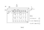
圖1是示意性地示出一般車輛抬頭顯示器(head-up display;HUD)系統的視圖。FIG. 1 is a view schematically showing a general vehicle head-up display (HUD) system.
一般車輛抬頭顯示器(HUD)系統10可包含:顯示器1,產生及輸出影像;及光學系統2,朝向車輛擋風玻璃導向影像。A general vehicle head-up display (HUD)
光學系統2使用如圖1中所示出的多個鏡面3及鏡面4,以便在確保顯示器1與擋風玻璃之間的光學路徑的同時,減小抬頭顯示器(HUD)系統10的總體積。The
儘管如上文使用多個鏡面3及鏡面4,但歸因於確保顯示器1與多個鏡面3及鏡面4之間的距離,所以將抬頭顯示器(HUD)系統10的總體積減小至約10公升是有限制的。Although
在此抬頭顯示器(HUD)系統中,難以形成寬的眼睛運動盒(eye motion box;EMB),所述眼睛運動盒是司機可經由擋風玻璃視覺上識別影像的區域。因此,考慮到司機的瞳孔的視覺軸線與影像的可視角度,司機需要不方便地且直接地調整多個鏡面3及鏡面4之間的角度以使得影像可到達擋風玻璃的有限範圍。In this head-up display (HUD) system, it is difficult to form a wide eye motion box (EMB), which is an area where the driver can visually recognize images through the windshield. Therefore, considering the visual axis of the driver's pupil and the viewing angle of the image, the driver needs to inconveniently and directly adjust the angle between the
此外,在先前技術中,為擴展眼睛運動盒,使用第一波導在豎直方向上擴展入射光,且接著使用第二波導在水平方向上擴展入射光,亦即,使用兩個波導在豎直方向上及水平方向上擴展入射光。然而,在使用兩個波導的情況下,在結構上減小體積方面存在限制。此外,需要精確地配置兩個波導以使得自第一波導發射的光入射在第二波導的適當位置處。因此,在製造製程中需要精確度,從而導致製造成本及製造時間的增加。In addition, in the prior art, to expand the eye movement box, the first waveguide is used to expand the incident light in the vertical direction, and then the second waveguide is used to expand the incident light in the horizontal direction, that is, two waveguides are used to expand the incident light in the vertical direction. Expand the incident light in the horizontal direction and in the horizontal direction. However, in the case of using two waveguides, there is a limitation in reducing the size in structure. In addition, it is necessary to accurately configure the two waveguides so that the light emitted from the first waveguide is incident at the appropriate position of the second waveguide. Therefore, precision is required in the manufacturing process, which leads to an increase in manufacturing cost and manufacturing time.
上述先前技術是本發明人已經擁有的用於推導本發明的實施例的技術資訊或在推導本發明的實施例的製程中獲得的技術資訊,且在本發明的實施例的申請案提交之前,不一定能說先前技術是向一般公眾揭露的公開已知的技術。The above-mentioned prior art is the technical information used to derive the embodiment of the present invention already owned by the inventor or technical information obtained during the process of deriving the embodiment of the present invention, and prior to the submission of the application for the embodiment of the present invention, It is not necessarily said that the prior art is a publicly known technology that is disclosed to the general public.
技術問題technical problem
本發明的實施例意欲提供一種可適用於抬頭顯示器的全像波導。The embodiment of the present invention intends to provide a holographic waveguide applicable to a head-up display.
本發明待解決的問題不限於前述問題,且其他未提及的問題將由所屬領域中具通常知識者自以下描述清晰地理解。The problems to be solved by the present invention are not limited to the aforementioned problems, and other unmentioned problems will be clearly understood by those with ordinary knowledge in the field from the following description.
技術解決方案Technical solutions
根據本發明的態樣的實施例提供一種全像波導,包含:光導單元,配置以導引光;第一全像光學元件,安置於光導單元的一個表面或另一表面上以使得自光源輸出的光輸入光導單元且在光導單元上受導引且配置以使輸入光繞射;第二全像光學元件,安置於光導單元的一個表面及另一表面中的任一者上,且配置以接收由第一全像光學元件繞射且經由光導單元導引的光,且配置以藉由繞射將接收到的光的一部分導向至光導單元的一個表面及另一表面中的另一者;第三全像光學元件,安置於與第二全像光學元件所安置的光導單元的表面相對的表面上,且配置以接收由第二全像光學元件繞射的光且配置以藉由繞射將接收到的光導引至光導單元上的區域,所述區域與第一全像光學元件及第二全像光學元件所安置的區域不同;以及第四全像光學元件,配置以接收由第三全像光學元件繞射的光,且配置以允許藉由繞射自光導單元輸出接收到的光。An embodiment according to aspects of the present invention provides a holographic waveguide, including: a light guide unit configured to guide light; and a first holographic optical element disposed on one surface or the other surface of the light guide unit to enable output from the light source The light enters the light guide unit and is guided on the light guide unit and configured to diffract the input light; the second holographic optical element is arranged on either one of the surface of the light guide unit and the other surface, and is configured to Receiving light diffracted by the first holographic optical element and guided by the light guide unit, and configured to guide a part of the received light to the other of one surface and the other surface of the light guide unit by diffraction; The third holographic optical element is disposed on the surface opposite to the surface of the light guide unit on which the second holographic optical element is disposed, and is configured to receive the light diffracted by the second holographic optical element and configured to diffract Guide the received light to an area on the light guide unit, the area being different from the area where the first holographic optical element and the second holographic optical element are arranged; and the fourth holographic optical element is configured to receive the second holographic optical element The three-holographic optical element diffracts light and is configured to allow the received light to be output from the light guide unit by diffraction.
在本實施例中,第一全像光學元件及第二全像光學元件中的每一者可包含高折射部分及低折射部分沿第一方向交替地安置的圖案,且第三全像光學元件及第四全像光學元件中的每一者可包含高折射部分及低折射部分沿垂直於第一方向的第二方向交替地安置的圖案。In this embodiment, each of the first holographic optical element and the second holographic optical element may include a pattern in which high-refractive portions and low-refractive portions are alternately arranged along the first direction, and the third holographic optical element Each of and the fourth holographic optical element may include a pattern in which high-refraction portions and low-refraction portions are alternately arranged in a second direction perpendicular to the first direction.
在本實施例中,第二全像光學元件可配置以使得其圖案的繞射效率沿第一方向提高。In this embodiment, the second holographic optical element can be configured such that the diffraction efficiency of its pattern is improved along the first direction.
在本實施例中,第三全像光學元件可配置以使得其圖案的繞射效率在沿第一方向的區域內實質上均勻。In this embodiment, the third holographic optical element may be configured such that the diffraction efficiency of its pattern is substantially uniform in the region along the first direction.
在本實施例中,第四全像光學元件可配置以使得其圖案的繞射效率沿第二方向提高。In this embodiment, the fourth holographic optical element can be configured so that the diffraction efficiency of its pattern is improved along the second direction.
在本實施例中,相位延遲膜可安置於第二全像光學元件與第三全像光學元件之間。In this embodiment, the phase retardation film may be disposed between the second holographic optical element and the third holographic optical element.
在本實施例中,相位延遲膜可安置於光導單元與第三全像光學元件之間。In this embodiment, the phase retardation film may be disposed between the light guide unit and the third holographic optical element.
有利影響Beneficial effects
根據本發明的實施例的全像波導可有助於縮小抬頭顯示器的大小。The holographic waveguide according to the embodiment of the present invention can help reduce the size of a head-up display.
此外,全像波導具有能夠在維持高亮度的同時顯示影像的優勢。In addition, the holographic waveguide has the advantage of being able to display images while maintaining high brightness.
本發明將結合隨附圖式參考以下詳細描述而變得顯而易見。然而,本發明不限於此類實施例且可以各種形式實現。下文待描述的實施例僅為使本發明的揭露內容完善且輔助本發明涉及的所屬領域中具通常知識者徹底理解本發明的範疇而提供的實施例。本發明僅由隨附申請專利範圍的範疇定義。本文中所使用的術語僅出於描述實施例的目的且不意欲限制本發明。如本文中所使用,除非上下文另外清晰地指示,否則單數形式「一(a、an)」以及「所述」意欲亦包含複數形式。當在本文中使用時,術語「包括(comprises)」及/或「包括(comprising)」所陳述組件、步驟、操作及/或元件不排除一或多個其他組件、步驟、操作及/或元件的存在或增加。諸如第一及第二的術語可用於描述各種組件,但組件不受術語限制。所述術語僅用於將一個組件與另一組件區分開。The present invention will become apparent with reference to the following detailed description in conjunction with the accompanying drawings. However, the present invention is not limited to such embodiments and can be implemented in various forms. The embodiments to be described below are only examples provided to complete the disclosure content of the present invention and assist those with ordinary knowledge in the field to which the present invention relates to thoroughly understand the scope of the present invention. The present invention is only defined by the scope of the attached patent application. The terms used herein are only for the purpose of describing the embodiments and are not intended to limit the present invention. As used herein, unless the context clearly indicates otherwise, the singular forms "a, an" and "the" are intended to also include the plural forms. As used herein, the terms "comprises" and/or "comprising" stated components, steps, operations and/or elements do not exclude one or more other components, steps, operations and/or elements The existence or increase. Terms such as first and second can be used to describe various components, but the components are not limited by the terms. The terms are only used to distinguish one component from another.
在本說明書中,術語「光導單元」可定義為用於藉由使用全內反射在內部中導引光的結構。全內反射的條件為光導單元的折射率需要大於鄰近於光導單元的表面的周圍介質的折射率。光導單元可由玻璃及/或塑膠材料形成,且可為透明或半透明的。光導單元可以板型以各種佈局形成。術語「板」意謂一種三維結構,所述三維結構在其相對側上在一個表面與另一表面之間具有預定厚度,且一個表面及另一表面可為實質上平坦的平面,但一個表面及另一表面中的至少一者可在一個維度或兩個維度上形成為彎曲的。舉例而言,板型光導單元可在一個維度上彎曲,以使得其一個表面及/或另一表面可具有對應於圓柱體的側表面中的一些的形狀。然而,較佳地,藉由板型光導單元的彎曲形成的曲率具有足夠大的曲率半徑以促進全內反射,以便在光導單元上導引光。In this specification, the term "light guide unit" can be defined as a structure for guiding light inside by using total internal reflection. The condition of total internal reflection is that the refractive index of the light guide unit needs to be greater than the refractive index of the surrounding medium adjacent to the surface of the light guide unit. The light guide unit may be formed of glass and/or plastic materials, and may be transparent or translucent. The light guide unit may be formed in various layouts in a plate type. The term "plate" means a three-dimensional structure having a predetermined thickness between one surface and the other surface on its opposite side, and one surface and the other surface may be substantially flat planes, but one surface At least one of and the other surface may be formed to be curved in one dimension or two dimensions. For example, the plate-type light guide unit may be curved in one dimension, so that one surface and/or the other surface thereof may have a shape corresponding to some of the side surfaces of the cylinder. However, preferably, the curvature formed by the bending of the plate-type light guide unit has a radius of curvature large enough to promote total internal reflection so as to guide light on the light guide unit.
在本說明書中,術語「全像光學元件」可指高折射部分及低折射部分沿預定方向交替地安置的全像光柵圖案,且到達全像光學元件的光的光學路徑可歸因於其繞射而改變。可藉由在諸如光聚合物的感光性材料上的多個雷射的干涉來記錄此全像光柵圖案。全像光學元件可理解為用於藉由安置於光導單元的一個表面或另一表面上而使光在光導單元上繞射來改變光學路徑的結構。In this specification, the term "holographic optical element" may refer to a holographic grating pattern in which high-refractive parts and low-refractive parts are alternately arranged in a predetermined direction, and the optical path of light reaching the holographic optical element can be attributed to its winding Shoot and change. This holographic grating pattern can be recorded by the interference of multiple lasers on a photosensitive material such as a photopolymer. The holographic optical element can be understood as a structure used to change the optical path by diffracting light on the light guide unit by being placed on one surface or the other surface of the light guide unit.
在本說明書中,全像光學元件可包含高折射部分及低折射部分沿預定方向交替地安置的全像光柵圖案,且全像光柵圖案的縱向方向可定義為與高折射部分及低折射部分交替地安置的方向垂直的方向。In this specification, the holographic optical element may include holographic grating patterns in which high-refraction parts and low-refraction parts are alternately arranged in a predetermined direction, and the longitudinal direction of the holographic grating pattern may be defined as alternating with high-refraction parts and low-refraction parts The direction of the ground placement is vertical.
在本說明書中,在光導單元上全內反射的光的光學路徑可歸因於光由全像光學元件部分繞射而改變,且其餘部分可在繞射之前沿光學路徑全反射,且術語「繞射效率」可指藉由將光學路徑歸因於繞射而已改變的繞射光的光量除以即將繞射之前的光量而獲得的值。In this specification, the optical path of the light totally internally reflected on the light guide unit can be changed due to the partial diffraction of the light by the holographic optical element, and the remaining part can be totally reflected along the optical path before being diffracted, and the term " "Diffraction efficiency" may refer to a value obtained by dividing the amount of diffracted light whose optical path has been changed due to diffraction by the amount of light immediately before the diffraction.
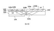
圖2是示意性地示出根據本發明的一個實施例的全像波導的視圖,且圖3是示意性地示出經由圖2中所示出的全像波導的光學路徑及光學路徑上的主要偏振方向的視圖。FIG. 2 is a view schematically showing a holographic waveguide according to an embodiment of the present invention, and FIG. 3 is a diagram schematically showing an optical path and an optical path through the holographic waveguide shown in FIG. 2 View of the main polarization direction.
圖4是示出自側面A觀察的圖3中所示出的全像波導的視圖,且圖5是示出自側面B觀察的圖3中所示出的全像波導的視圖。4 is a view showing the holographic waveguide shown in FIG. 3 viewed from the side A, and FIG. 5 is a view showing the holographic waveguide shown in FIG. 3 viewed from the side B.
參考圖2至圖5,全像波導100可包含光導單元110、第一全像光學元件120、第二全像光學元件130、第三全像光學元件140、第四全像光學元件150以及相位延遲膜160。2 to 5, the
光導單元110可配置成藉由使用全內反射在內部中導引光。The
第一全像光學元件120可安置於光導單元110的一個表面110a或另一表面110b上以使得自光源(未示出)輸出的光L可輸入且在光導單元110上受導引,且可配置成使輸入光L繞射。光源可接收具有影像資訊的電信號且輸出用於影像資訊的影像顯示光。作為光源,舉例而言,可使用液晶顯示器(liquid crystal display;LCD)面板、由有機發光二極體(organic light emitting diodes;OLED)構成的顯示面板(下文中稱為有機發光顯示面板)或諸如雷射束掃描投影機的顯示裝置。圖2示出一個實施例,其中第一全像光學元件120安置於光導單元110的一個表面110a上。The first holographic
第一全像光學元件120可包含高折射部分120a及低折射部分120b沿預定方向交替地安置的全像光柵圖案。第一全像光學元件120的高折射部分120a及低折射部分120b交替地安置的方向定義為第一方向,且可為基於圖2的x軸方向。第一全像光學元件120的全像光柵圖案的縱向方向可為垂直於第一方向的第二方向,亦即,基於圖2的z軸方向。The first holographic
第二全像光學元件130可安置於光導單元110的一個表面110a及另一表面110b中的任一者上,且可配置成接收由第一全像光學元件120繞射且經由光導單元110導引的光L1,且可配置成藉由繞射將接收到的光的部分導向至光導單元110的一個表面110a及另一表面110b中的另一者。在一個實施例中,第二全像光學元件130沿第一方向與第一全像光學元件120隔開預定間隔安置,且圖2至圖5示出第二全像光學元件130安置於光導單元110的一個表面110a上;然而,本揭露不限於此。The second holographic
第二全像光學元件130可包含高折射部分130a及低折射部分130b沿預定方向交替地安置的全像光柵圖案。與在第一全像光學元件120的情況中一樣,第二全像光學元件130的高折射部分130a及低折射部分130b交替地安置的方向可為第一方向,亦即,基於圖2的x軸方向。第二全像光學元件130的全像光柵圖案的縱向方向可為垂直於第一方向的第二方向,亦即,基於圖2的z軸方向。The second holographic
同時,基於圖2至圖5中所示出的實施例,第二全像光學元件130配置成接收由第一全像光學元件120繞射且經由光導單元110導引的光L1,配置成藉由繞射將光L1的部分導向至光導單元110的另一表面110b,且配置成經由現存光學路徑藉由光導單元110上的全反射來導引光L1的其餘部分。具體而言,最初由第二全像光學元件130接收的光L1在沿例如第一方向的特定方向以預定間隔分離的每一點處部分地繞射,繞射光L2導向至光導單元110的另一表面110b,且其餘的光沿第一方向在光導單元110中被全反射且被導引,以使得最後可實現一維擴展。At the same time, based on the embodiments shown in FIGS. 2 to 5, the second holographic
第三全像光學元件140可安置於與第二全像光學元件130安置於其上的表面相對的表面上,且可配置成接收來自第二全像光學元件130的繞射光L2及繞射光L2',且可配置成藉由繞射將接收到的光L2及L2'導引至光導單元110上的與第一全像光學元件120及第二全像光學元件130所安置的區域不同的區域。在一個實施例中,因為第二全像光學元件130安置於光導單元110的一個表面110a上,所以第三全像光學元件140可安置於光導單元110的另一表面110b上,所述另一表面110b是與一個表面110a相對的表面。The third holographic
第三全像光學元件140可包含高折射部分140a及低折射部分140b沿預定方向交替地安置的全像光柵圖案。第三全像光學元件140的高折射部分140a及低折射部分140b交替地安置的方向可為第二方向,亦即,基於圖2的z軸方向,所述第二方向垂直於第一全像光學元件120及第二全像光學元件130的全像光柵圖案配置的第一方向。第三全像光學元件140的全像光柵圖案的縱向方向可為垂直於第二方向的第一方向,亦即,基於圖2的x軸方向。The third holographic
第四全像光學元件150可配置成接收來自第三全像光學元件140的繞射光L3,且可配置成允許藉由繞射自光導單元110輸出接收到的光L3。The fourth holographic
第四全像光學元件150可安置於光導單元110的一個表面110a及另一表面110b中的任一者上,且圖2至圖5示出一個實施例,其中第四全像光學元件150安置於光導單元110的另一表面110b上,所述另一表面110b是第三全像光學元件140安置於其上的側面。The fourth holographic
第四全像光學元件150可包含高折射部分150a及低折射部分150b沿預定方向交替地安置的全像光柵圖案。與在第三全像光學元件140的情況中一樣,第四全像光學元件150的高折射部分150a及低折射部分150b交替地安置的方向可為第二方向,亦即,基於圖2的z軸方向。第四全像光學元件150的全像光柵圖案的縱向方向可為垂直於第二方向的第一方向,亦即,基於圖2的x軸方向。The fourth holographic
同時,基於圖2至圖5中所示出的實施例,第四全像光學元件150配置成接收藉由第三全像光學元件140繞射且經由光導單元110導引的光L3,配置成允許藉由繞射自光導單元110輸出光L3的部分,且配置成經由現存光學路徑藉由光導單元110上的全反射來導引光L3的其餘部分。具體而言,最初由第四全像光學元件150接收的光L3在沿例如第二方向的特定方向以預定間隔分離的每一點處部分地繞射,繞射光L4自光導單元110輸出,且其餘的光沿第二方向在光導單元110中被全反射且被導引,以使得最後可實現一維擴展。同時,最初由第四全像光學元件150接收的光L3是已由第二全像光學元件130沿第一方向擴展且已經由第三全像光學元件140到達第四全像光學元件150的光。因為此類光L3沿第二方向經由第四全像光學元件150擴展,所以相較於由第一全像光學元件120自光源接收的光L,經由第四全像光學元件150自光導單元110輸出的光L4處於二維擴展的狀態。如上所述,由於在廣泛區域內實施二維擴展,因此可廣泛地形成眼睛運動盒(EMB),所述眼睛運動盒是可安置觀測者的瞳孔以使得可在視覺上識別輸出光的區域。At the same time, based on the embodiments shown in FIGS. 2 to 5, the fourth holographic
在本實施例中,較佳地,第二全像光學元件130配置以使得其全像光柵圖案的繞射效率沿第一方向提高。第二全像光學元件130可配置以使得其全像光柵圖案的效率在10%至100%之間逐漸提高。由第二全像光學元件130自第一全像光學元件120接收的光L1在作為主要方向的第一方向上全反射,在所述第一方向中,全像光柵圖案配置在光導單元110上。藉由全像光柵圖案將光L2的一些與繞射一起在全反射路徑上進行劃分,以使得其光學路徑導向至第二全像光學元件130。因此,在第一方向作為主要方向的情況下,光量沿全反射路徑減小。因此,即使到達全像光柵圖案的光量沿全反射路徑減小,當第二全像光學元件130配置以使得其繞射效率沿第一方向提高時,經由第二全像光學元件130的全像光柵圖案繞射且導向至第三全像光學元件140的光L2的量可彼此相似。同時,全像光柵圖案的繞射效率與高折射部分的厚度及/或高度相關。亦即,藉由沿預定方向增加高折射部分的厚度及/或高度可提高沿預定方向配置的全像光柵圖案的繞射效率。In this embodiment, preferably, the second holographic
在本實施例中,較佳地,第三全像光學元件140配置以使得其全像光柵圖案的繞射效率在沿第一方向的區域內實質上均勻,且繞射效率較佳地為80%或大於80%。在第三全像光學元件140中,全像光柵圖案沿第二方向配置,且光可藉由繞射沿第二方向實質上導向至安置第三全像光學元件140的區域。同時,由第三全像光學元件140自第二全像光學元件130接收的光L2及光L2'具有與上文所述的光量相似的光量,且不由第三全像光學元件140的全像光柵圖案在第一方向上全反射。因此,有必要藉由允許繞射效率在沿第一方向的區域內均勻來維持藉由繞射的光L3的光量彼此相似。同時,藉由允許高折射部分的厚度及/或高度沿預定方向實質上相同,沿預定方向配置的全像光柵圖案的繞射效率可實質上均勻。In this embodiment, preferably, the third holographic
在本實施例中,較佳地,第四全像光學元件150配置以使得其全像光柵圖案的繞射效率沿第二方向提高。第四全像光學元件150可配置以使得全像光柵圖案的效率在10%至100%之間逐漸提高。由第四全像光學元件150自第三全像光學元件140接收的光L3在作為主要方向的第二方向上全反射,在所述第二方向中,全像光柵圖案配置在光導單元110上。藉由全像光柵圖案將光L4的一些與繞射一起在全反射路徑上進行劃分,以使得其光學路徑形成於光L4自光導單元110輸出的方向中。因此,在第二方向作為主要方向的情況下,光量沿全反射路徑減小。因此,即使到達全像光柵圖案的光量沿全反射路徑減小,當第四全像光學元件150配置以使得其繞射效率沿第二方向提高時,經由第四全像光學元件150的全像光柵圖案繞射且自光導單元110輸出的光L4的量可彼此相似。In this embodiment, preferably, the fourth holographic
同時,由於光的偏振方向平行於全像光學元件中的全像光柵圖案的縱向方向,因此由全像光學元件接收的光的繞射效率提高。At the same time, since the polarization direction of the light is parallel to the longitudinal direction of the holographic grating pattern in the holographic optical element, the diffraction efficiency of the light received by the holographic optical element is improved.
具體而言,第一全像光學元件120及第二全像光學元件130主要使在平行於第二方向的方向中偏振的光繞射,此是因為其全像光柵圖案的縱向方向是第二方向。因此,經由第一全像光學元件120導向至第二全像光學元件130的光L1及經由第二全像光學元件130導向至第三全像光學元件140的光L2的主要偏振方向可為第二方向。Specifically, the first holographic
同時,第三全像光學元件140主要使在平行於第一方向的方向中偏振的光繞射,此是因為其全像光柵圖案的縱向方向是垂直於第二方向的第一方向。然而,因為經由第二全像光學元件130導向至第三全像光學元件140的光L2的主要偏振方向是第二方向,所以可由第三全像光學元件140的全像光柵圖案繞射的光的量顯著地減小。At the same time, the third holographic
在此方面,在本實施例中,藉由在第二全像光學元件130與第三全像光學元件140之間安置相位延遲膜160,有可能將經由第二全像光學元件130導向至第三全像光學元件140的光L2的主要偏振方向自第二方向切換至第一方向。在此,相位延遲膜160可安置於光導單元110與第三全像光學元件140之間。作為相位延遲膜160,可使用λ/4相位延遲膜、λ/2相位延遲膜及其類似者;然而,本發明不限於此且可使用任何配置,只要其可將偏振方向自第二方向切換至第一方向即可。In this regard, in this embodiment, by disposing the
由相位延遲膜160將主要偏振方向切換至第一方向的光L2'到達第三全像光學元件140,且第三全像光學元件140主要使在平行於第一方向的方向中偏振的光繞射。因此,使光損耗最小化且光L2'可導向至第四全像光學元件150。在此情況下,有可能在維持高光亮度的同時自光導單元110輸出影像。The light L2' whose main polarization direction is switched to the first direction by the
根據本發明的實施例的全像波導可用作經由繞射的波導,同時最小化光損耗,由此有助於縮小抬頭顯示器的大小。The holographic waveguide according to the embodiment of the present invention can be used as a waveguide via diffraction while minimizing light loss, thereby helping to reduce the size of a head-up display.
儘管本發明已關於上文所描述的較佳實施例進行描述,但在不脫離本發明的主題及範疇的情況下可進行各種校正或修改。因此,隨附申請專利範圍將包含此類校正或修改,只要所述校正或修改屬於本發明的主題即可。Although the present invention has been described with respect to the preferred embodiments described above, various corrections or modifications can be made without departing from the subject and scope of the present invention. Therefore, the scope of the attached patent application will include such corrections or modifications, as long as the corrections or modifications belong to the subject matter of the present invention.
1:顯示器2:光學系統3、4:鏡面10:抬頭顯示器系統100:全像波導110:光導單元110a、110b:表面120:第一全像光學元件120a、130a、140a、150a:高折射部分120b、130b、140b、150b:低折射部分130:第二全像光學元件140:第三全像光學元件150:第四全像光學元件160:相位延遲膜A、B:側面L、L1:光L2、L2'、L3、L4:繞射光1: display2:
圖1是示意性地示出一般車輛抬頭顯示器系統的視圖。圖2是示意性地示出根據本發明的一個實施例的全像波導的視圖。圖3是示意性地示出經由圖2中所示出的全像波導的光學路徑及光學路徑上的主要偏振方向的視圖。圖4是示出自側面A觀察的圖3中所示出的全像波導的視圖。圖5是示出自側面B觀察的圖3中所示出的全像波導的視圖。FIG. 1 is a view schematically showing a general vehicle head-up display system.Fig. 2 is a view schematically showing a holographic waveguide according to an embodiment of the present invention.FIG. 3 is a view schematically showing the optical path through the holographic waveguide shown in FIG. 2 and the main polarization direction on the optical path.FIG. 4 is a view showing the holographic waveguide shown in FIG. 3 viewed from the side A.FIG. 5 is a view showing the holographic waveguide shown in FIG. 3 viewed from the side B.
100:全像波導100: Holographic Waveguide
110a、110b:表面110a, 110b: surface
120:第一全像光學元件120: The first holographic optical element
120a、130a、140a、150a:高折射部分120a, 130a, 140a, 150a: high refractive part
120b、130b、140b、150b:低折射部分120b, 130b, 140b, 150b: low refractive part
130:第二全像光學元件130: second holographic optical element
140:第三全像光學元件140: The third holographic optical element
150:第四全像光學元件150: The fourth holographic optical element
Claims (7)
Translated fromChineseApplications Claiming Priority (2)
| Application Number | Priority Date | Filing Date | Title |
|---|---|---|---|
| KR10-2019-0124013 | 2019-10-07 | ||
| KR1020190124013AKR102601442B1 (en) | 2019-10-07 | 2019-10-07 | Holographic Waveguide |
Publications (1)
| Publication Number | Publication Date |
|---|---|
| TW202117374Atrue TW202117374A (en) | 2021-05-01 |
Family
ID=75437304
Family Applications (1)
| Application Number | Title | Priority Date | Filing Date |
|---|---|---|---|
| TW109134675ATW202117374A (en) | 2019-10-07 | 2020-10-07 | Holographic waveguide |
Country Status (7)
| Country | Link |
|---|---|
| US (1) | US12124033B2 (en) |
| EP (1) | EP3958030A4 (en) |
| JP (1) | JP7305252B2 (en) |
| KR (1) | KR102601442B1 (en) |
| CN (1) | CN113692549B (en) |
| TW (1) | TW202117374A (en) |
| WO (1) | WO2021071210A1 (en) |
Families Citing this family (2)
| Publication number | Priority date | Publication date | Assignee | Title |
|---|---|---|---|---|
| WO2023188720A1 (en)* | 2022-03-31 | 2023-10-05 | パナソニックIpマネジメント株式会社 | Optical system and head-up display system equipped with same |
| CN118311771A (en)* | 2023-01-09 | 2024-07-09 | 华为技术有限公司 | Optical assembly, projection device and transport tool |
Family Cites Families (30)
| Publication number | Priority date | Publication date | Assignee | Title |
|---|---|---|---|---|
| EP1068548B1 (en) | 1998-04-02 | 2003-11-12 | Elop Electro-Optics Industries Ltd. | Holographic optical devices |
| JP4727034B2 (en)* | 2000-11-28 | 2011-07-20 | オリンパス株式会社 | Observation optical system and imaging optical system |
| US20060126181A1 (en) | 2004-12-13 | 2006-06-15 | Nokia Corporation | Method and system for beam expansion in a display device |
| US9081178B2 (en) | 2005-09-07 | 2015-07-14 | Bae Systems Plc | Projection display for displaying an image to a viewer |
| JP2007219106A (en) | 2006-02-16 | 2007-08-30 | Konica Minolta Holdings Inc | Optical device for expanding diameter of luminous flux, video display device and head mount display |
| JP2008064914A (en) | 2006-09-06 | 2008-03-21 | Konica Minolta Holdings Inc | Holographic exposure method, optical element and video display device |
| JP5151518B2 (en)* | 2008-02-07 | 2013-02-27 | ソニー株式会社 | Optical device and image display device |
| WO2009127849A1 (en) | 2008-04-14 | 2009-10-22 | Bae Systems Plc | Improvements in or relating to waveguides |
| US10274660B2 (en) | 2008-11-17 | 2019-04-30 | Luminit, Llc | Holographic substrate-guided wave-based see-through display |
| US11320571B2 (en)* | 2012-11-16 | 2022-05-03 | Rockwell Collins, Inc. | Transparent waveguide display providing upper and lower fields of view with uniform light extraction |
| KR20140027812A (en) | 2012-08-27 | 2014-03-07 | 삼성전자주식회사 | Phase mask and holographic recording apparatus employing the same |
| CN102928981B (en) | 2012-11-14 | 2016-08-03 | 中航华东光电有限公司 | Optical system of holographic optical waveguide helmet display |
| JP6187045B2 (en) | 2013-08-30 | 2017-08-30 | セイコーエプソン株式会社 | Optical device and image display apparatus |
| JP6232863B2 (en) | 2013-09-06 | 2017-11-22 | セイコーエプソン株式会社 | Optical device and image display apparatus |
| RU2603238C2 (en) | 2014-07-15 | 2016-11-27 | Самсунг Электроникс Ко., Лтд. | Light-guide structure, holographic optical device and imaging system |
| GB2529003B (en) | 2014-08-03 | 2020-08-26 | Wave Optics Ltd | Optical device |
| CN112925100B (en) | 2014-09-29 | 2023-10-31 | 奇跃公司 | Optical system |
| JP6519256B2 (en) | 2015-03-23 | 2019-05-29 | セイコーエプソン株式会社 | Beam diameter expanding element and display device |
| US10247943B1 (en)* | 2015-05-18 | 2019-04-02 | Rockwell Collins, Inc. | Head up display (HUD) using a light pipe |
| US9791696B2 (en)* | 2015-11-10 | 2017-10-17 | Microsoft Technology Licensing, Llc | Waveguide gratings to improve intensity distributions |
| US10359627B2 (en) | 2015-11-10 | 2019-07-23 | Microsoft Technology Licensing, Llc | Waveguide coatings or substrates to improve intensity distributions having adjacent planar optical component separate from an input, output, or intermediate coupler |
| CN107632406A (en) | 2016-07-18 | 2018-01-26 | 北京灵犀微光科技有限公司 | Holographic waveguide, augmented reality display system and display method |
| JP6972121B2 (en) | 2016-10-05 | 2021-11-24 | マジック リープ, インコーポレイテッドMagic Leap, Inc. | Processing of non-uniform diffraction gratings |
| EP3625616B1 (en) | 2017-05-16 | 2025-06-25 | Magic Leap, Inc. | Systems and methods for mixed reality |
| FI129400B (en) | 2017-12-22 | 2022-01-31 | Dispelix Oy | Diffractive waveguide element and diffractive waveguide display |
| KR102486828B1 (en)* | 2018-01-12 | 2023-01-10 | 주식회사 엘지화학 | Diffractive light guide plate and display device including the same |
| KR102157554B1 (en)* | 2018-01-12 | 2020-09-18 | 주식회사 엘지화학 | Diffractive light guide plate and display device including the same |
| KR102486664B1 (en)* | 2018-03-14 | 2023-01-10 | 주식회사 엘지화학 | Module of diffractive light guide plate |
| KR20190124013A (en) | 2018-04-25 | 2019-11-04 | (주)에이텍티앤 | Vehicle control system using traffic terminal with vehicle self-diagnosis function |
| CN109901298A (en) | 2019-02-28 | 2019-06-18 | 京东方科技集团股份有限公司 | Optical waveguide and display equipment |
- 2019
- 2019-10-07KRKR1020190124013Apatent/KR102601442B1/enactiveActive
- 2020
- 2020-10-06USUS17/607,196patent/US12124033B2/enactiveActive
- 2020-10-06WOPCT/KR2020/013586patent/WO2021071210A1/ennot_activeCeased
- 2020-10-06JPJP2021564176Apatent/JP7305252B2/enactiveActive
- 2020-10-06CNCN202080028571.XApatent/CN113692549B/enactiveActive
- 2020-10-06EPEP20874544.8Apatent/EP3958030A4/enactivePending
- 2020-10-07TWTW109134675Apatent/TW202117374A/enunknown
Also Published As
| Publication number | Publication date |
|---|---|
| CN113692549A (en) | 2021-11-23 |
| CN113692549B (en) | 2023-09-08 |
| US12124033B2 (en) | 2024-10-22 |
| US20220221719A1 (en) | 2022-07-14 |
| JP7305252B2 (en) | 2023-07-10 |
| KR20210041378A (en) | 2021-04-15 |
| EP3958030A4 (en) | 2022-06-08 |
| KR102601442B1 (en) | 2023-11-13 |
| WO2021071210A1 (en) | 2021-04-15 |
| EP3958030A1 (en) | 2022-02-23 |
| JP2022530250A (en) | 2022-06-28 |
Similar Documents
| Publication | Publication Date | Title |
|---|---|---|
| EP3223059B1 (en) | Light guide and display device having two reflective holographic elements | |
| US11960087B2 (en) | Optical device and display apparatus with same images for left and right eyes | |
| CN105929535B (en) | Image display device | |
| JP5528623B2 (en) | Incoherent device and optical apparatus using the same | |
| US20170115484A1 (en) | Image display device | |
| US12216303B2 (en) | Light-guide plate, manufacturing method for the same, light-guide plate module, and image display device | |
| US20230028757A1 (en) | Image display element, image display device, and image display method | |
| TWI753617B (en) | Image Display Components and Devices | |
| CN113534480A (en) | Optical device with reduced chromatic aberration and display device including the same | |
| TW202117374A (en) | Holographic waveguide | |
| CN115598843A (en) | Optical device and display device including same | |
| CN115480335A (en) | Diffractive waveguide, optical module, and electronic device | |
| CN218567743U (en) | Optical devices and near-eye display devices | |
| CN218122364U (en) | Optical device and display apparatus | |
| US10852555B2 (en) | Head-mounted display apparatus | |
| JP2022129525A (en) | image projection device | |
| KR102858911B1 (en) | Holographic waveguide and display device including the same | |
| KR102802733B1 (en) | Parts for display device and display device using the same | |
| US20240201443A1 (en) | Image display apparatus and image display method | |
| TW202409470A (en) | Light guide display system including freeform volume grating | |
| JP2024505953A (en) | waveguide display device | |
| WO2024004288A1 (en) | Optical system and image display device | |
| KR20230082435A (en) | waveguide type display apparatus |