TW202109957A - Membrane-electrode assembly, method for manufacturing the same, and fuel cell comprising the same - Google Patents
Membrane-electrode assembly, method for manufacturing the same, and fuel cell comprising the sameDownload PDFInfo
- Publication number
- TW202109957A TW202109957ATW109121779ATW109121779ATW202109957ATW 202109957 ATW202109957 ATW 202109957ATW 109121779 ATW109121779 ATW 109121779ATW 109121779 ATW109121779 ATW 109121779ATW 202109957 ATW202109957 ATW 202109957A
- Authority
- TW
- Taiwan
- Prior art keywords
- sub
- electrode
- gasket
- membrane
- electrolyte membrane
- Prior art date
Links
Images


Classifications
- H—ELECTRICITY
- H01—ELECTRIC ELEMENTS
- H01M—PROCESSES OR MEANS, e.g. BATTERIES, FOR THE DIRECT CONVERSION OF CHEMICAL ENERGY INTO ELECTRICAL ENERGY
- H01M8/00—Fuel cells; Manufacture thereof
- H01M8/10—Fuel cells with solid electrolytes
- H01M8/1016—Fuel cells with solid electrolytes characterised by the electrolyte material
- H01M8/1018—Polymeric electrolyte materials
- H—ELECTRICITY
- H01—ELECTRIC ELEMENTS
- H01M—PROCESSES OR MEANS, e.g. BATTERIES, FOR THE DIRECT CONVERSION OF CHEMICAL ENERGY INTO ELECTRICAL ENERGY
- H01M8/00—Fuel cells; Manufacture thereof
- H01M8/02—Details
- H01M8/0271—Sealing or supporting means around electrodes, matrices or membranes
- H01M8/0273—Sealing or supporting means around electrodes, matrices or membranes with sealing or supporting means in the form of a frame
- H—ELECTRICITY
- H01—ELECTRIC ELEMENTS
- H01M—PROCESSES OR MEANS, e.g. BATTERIES, FOR THE DIRECT CONVERSION OF CHEMICAL ENERGY INTO ELECTRICAL ENERGY
- H01M8/00—Fuel cells; Manufacture thereof
- H01M8/02—Details
- H01M8/0271—Sealing or supporting means around electrodes, matrices or membranes
- H01M8/028—Sealing means characterised by their material
- H01M8/0284—Organic resins; Organic polymers
- H—ELECTRICITY
- H01—ELECTRIC ELEMENTS
- H01M—PROCESSES OR MEANS, e.g. BATTERIES, FOR THE DIRECT CONVERSION OF CHEMICAL ENERGY INTO ELECTRICAL ENERGY
- H01M8/00—Fuel cells; Manufacture thereof
- H01M8/02—Details
- H01M8/0271—Sealing or supporting means around electrodes, matrices or membranes
- H01M8/0286—Processes for forming seals
- H—ELECTRICITY
- H01—ELECTRIC ELEMENTS
- H01M—PROCESSES OR MEANS, e.g. BATTERIES, FOR THE DIRECT CONVERSION OF CHEMICAL ENERGY INTO ELECTRICAL ENERGY
- H01M8/00—Fuel cells; Manufacture thereof
- H01M8/10—Fuel cells with solid electrolytes
- H01M8/1004—Fuel cells with solid electrolytes characterised by membrane-electrode assemblies [MEA]
- H—ELECTRICITY
- H01—ELECTRIC ELEMENTS
- H01M—PROCESSES OR MEANS, e.g. BATTERIES, FOR THE DIRECT CONVERSION OF CHEMICAL ENERGY INTO ELECTRICAL ENERGY
- H01M8/00—Fuel cells; Manufacture thereof
- H01M8/10—Fuel cells with solid electrolytes
- H01M2008/1095—Fuel cells with polymeric electrolytes
- Y—GENERAL TAGGING OF NEW TECHNOLOGICAL DEVELOPMENTS; GENERAL TAGGING OF CROSS-SECTIONAL TECHNOLOGIES SPANNING OVER SEVERAL SECTIONS OF THE IPC; TECHNICAL SUBJECTS COVERED BY FORMER USPC CROSS-REFERENCE ART COLLECTIONS [XRACs] AND DIGESTS
- Y02—TECHNOLOGIES OR APPLICATIONS FOR MITIGATION OR ADAPTATION AGAINST CLIMATE CHANGE
- Y02E—REDUCTION OF GREENHOUSE GAS [GHG] EMISSIONS, RELATED TO ENERGY GENERATION, TRANSMISSION OR DISTRIBUTION
- Y02E60/00—Enabling technologies; Technologies with a potential or indirect contribution to GHG emissions mitigation
- Y02E60/30—Hydrogen technology
- Y02E60/50—Fuel cells
- Y—GENERAL TAGGING OF NEW TECHNOLOGICAL DEVELOPMENTS; GENERAL TAGGING OF CROSS-SECTIONAL TECHNOLOGIES SPANNING OVER SEVERAL SECTIONS OF THE IPC; TECHNICAL SUBJECTS COVERED BY FORMER USPC CROSS-REFERENCE ART COLLECTIONS [XRACs] AND DIGESTS
- Y02—TECHNOLOGIES OR APPLICATIONS FOR MITIGATION OR ADAPTATION AGAINST CLIMATE CHANGE
- Y02P—CLIMATE CHANGE MITIGATION TECHNOLOGIES IN THE PRODUCTION OR PROCESSING OF GOODS
- Y02P70/00—Climate change mitigation technologies in the production process for final industrial or consumer products
- Y02P70/50—Manufacturing or production processes characterised by the final manufactured product
Landscapes
- Life Sciences & Earth Sciences (AREA)
- Engineering & Computer Science (AREA)
- Manufacturing & Machinery (AREA)
- Sustainable Development (AREA)
- Sustainable Energy (AREA)
- Chemical & Material Sciences (AREA)
- Chemical Kinetics & Catalysis (AREA)
- Electrochemistry (AREA)
- General Chemical & Material Sciences (AREA)
- Fuel Cell (AREA)
- Inert Electrodes (AREA)
Abstract
Description
Translated fromChinese本揭露是有關於膜電極組合、其製造方法以及包括其的燃料電池。This disclosure relates to a membrane electrode assembly, its manufacturing method, and a fuel cell including it.
聚合物電解質膜燃料電池(polymer electrolyte membrane fuel cell,PEMFC)—其為一種使用其中堆疊有各自包括膜電極組合(membrane-electrode assembly,MEA)及隔板的單元電池的結構來產生電的設備—已作為能夠替代化石燃料的下一代能源而引起了人們的關注,乃因所述聚合物電解質膜燃料電池表現出高能量效率及環境友好特性。Polymer electrolyte membrane fuel cell (PEMFC)—a device that uses a structure in which unit cells each including a membrane-electrode assembly (MEA) and a separator are stacked to generate electricity— It has attracted people's attention as a next-generation energy source that can replace fossil fuels because the polymer electrolyte membrane fuel cell exhibits high energy efficiency and environmentally friendly characteristics.
膜電極組合包括氧化電極(亦被稱為陽極或燃料電極)、還原電極(亦被稱為陰極或空氣電極)以及位於其間的電解質膜。聚合物電解質膜通常用作電解質膜。The membrane electrode assembly includes an oxidation electrode (also known as anode or fuel electrode), a reduction electrode (also known as cathode or air electrode), and an electrolyte membrane in between. Polymer electrolyte membranes are generally used as electrolyte membranes.
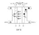
圖1是示出燃料電池的操作的示意圖。Fig. 1 is a schematic diagram showing the operation of a fuel cell.
當例如氫氣等燃料被供應至氧化電極21時,由於氫的氧化反應而在氧化電極21處產生氫離子(H+)及電子(e-)。所產生的氫離子經由電解質膜10轉移至還原電極22,且所產生的電子經由外部電路轉移至還原電極。在被供應包含氧的空氣的還原電極22處發生氧的還原反應。在還原電極22處,氧與氫離子及電子結合,由此一起產生水及熱。When fuel such as hydrogen is supplied to the
若引入氧化電極21的氫及引入還原電極22的空氣(氧)由於滲透而移動至相反的電極,則電池的效能劣化。因此,有必要防止氫及空氣(氧)滲透電解質膜10並混合。抑制氫及空氣(氧)由於滲透電解質膜10而彼此混合的能力與電解質膜10的效能直接相關。傳統上,墊圈接合至電解質膜10的邊緣,所述邊緣對應於膜電極組合的除電極之外的邊緣,以抑制氫及空氣(氧)由於滲透電解質膜10而移動至相反的電極。If the hydrogen introduced into the
在電解質膜10處設置墊圈的方法中,一般使用藉由加熱及按壓而在電解質膜10上層疊膜型子墊圈的方法。然而,在此種方法的情形中,(i)當藉由加熱及按壓來層疊子墊圈時,電極21及22被損壞,(ii)為調節子墊圈的厚度,必須單獨製備具有各種膜厚度的子墊圈,此為極其麻煩的,乃因子墊圈的最終厚度取決於膜厚度,(iii)當膜型子墊圈的一部分被貼附至電極的邊緣上時,在子墊圈處形成對應於電極厚度的台階,子墊圈的台階使後續製程(例如,形成/組裝氣體擴散層GDL的製程)中的可加工性劣化,並且(iv)所述台階在子墊圈膜與電極的側表面之間產生氣隙,由此顯著降低子墊圈膜的氣體洩漏防止功能。In the method of providing a gasket on the
[技術問題][technical problem]
本揭露的實施例提供能夠解決上述問題的膜電極組合、其製造方法以及包括其的燃料電池。The embodiments of the present disclosure provide a membrane electrode assembly capable of solving the above-mentioned problems, a manufacturing method thereof, and a fuel cell including the same.
本揭露的一個態樣是提供一種包括子墊圈的膜電極組合,所述子墊圈不具有會使後續製程中的可加工性劣化的台階或具有極小的所述台階。One aspect of the present disclosure is to provide a membrane electrode assembly including a sub-gasket, which does not have a step that would degrade the workability in a subsequent manufacturing process or has an extremely small step.
本揭露的另一態樣是提供一種在不會對電極造成損壞的情況下以高生產率製造具有優異效能的膜電極組合的方法。Another aspect of the present disclosure is to provide a method for manufacturing a membrane electrode assembly with excellent performance with high productivity without causing damage to the electrode.
本揭露的又一態樣是提供一種使用膜電極組合製造的燃料電池,所述膜電極組合的子墊圈不具有原本可能會使後續製程中的可加工性劣化的台階或具有極小的所述台階。[技術解決方案]Another aspect of the present disclosure is to provide a fuel cell manufactured using a membrane electrode assembly. The subgasket of the membrane electrode assembly does not have steps that would otherwise degrade the workability in subsequent processes or have extremely small steps. .[Technical Solution]
根據本揭露的態樣,提供一種膜電極組合,所述膜電極組合包括:電解質膜,具有第一表面及與所述第一表面相對的第二表面,所述電解質膜包括主動區域及圍繞所述主動區域的非主動區域;第一電極,設置在所述電解質膜的所述第一表面上方,所述第一電極覆蓋所述主動區域;第一子墊圈,設置在所述電解質膜的所述第一表面上方,所述第一子墊圈具有暴露出所述第一電極的中心部的第一窗口;第二電極,設置在所述電解質膜的所述第二表面上方,所述第二電極覆蓋所述主動區域;以及第二子墊圈,設置在所述電解質膜的所述第二表面上方,所述第二子墊圈具有暴露出所述第二電極的中心部的第二窗口,其中所述第一子墊圈包括與所述第一電極的邊緣重疊的第一重疊區域及覆蓋所述非主動區域的第一非重疊區域,在所述第一重疊區域與所述第一非重疊區域之間無台階或存在第一台階,由所述第一重疊區域及所述第一非重疊區域形成的所述第一台階的高度是所述第一電極的厚度的0.5倍或小於0.5倍,所述第二子墊圈包括與所述第二電極的邊緣重疊的第二重疊區域及覆蓋所述非主動區域的第二非重疊區域,並且在所述第二重疊區域與所述第二非重疊區域之間無台階或存在第二台階,由所述第二重疊區域及所述第二非重疊區域形成的所述第二台階的高度是所述第二電極的厚度的0.5倍或小於0.5倍。According to aspects of the present disclosure, a membrane electrode assembly is provided, the membrane electrode assembly includes: an electrolyte membrane having a first surface and a second surface opposite to the first surface, the electrolyte membrane including an active area and a surrounding area The non-active area of the active area; a first electrode disposed above the first surface of the electrolyte membrane, the first electrode covering the active area; a first sub-gasket disposed on all of the electrolyte membrane Above the first surface, the first sub-gasket has a first window exposing the center of the first electrode; a second electrode is disposed above the second surface of the electrolyte membrane, and the second An electrode covering the active area; and a second sub-gasket disposed above the second surface of the electrolyte membrane, the second sub-gasket having a second window exposing the center of the second electrode, wherein The first sub-gasket includes a first overlapping area overlapping with the edge of the first electrode and a first non-overlapping area covering the inactive area, where the first overlapping area and the first non-overlapping area There is no step or a first step between them, and the height of the first step formed by the first overlapping area and the first non-overlapping area is 0.5 times or less than the thickness of the first electrode, The second sub-gasket includes a second overlapping area overlapping with the edge of the second electrode and a second non-overlapping area covering the inactive area, and is in the second overlapping area and the second non-overlapping area There is no step between regions or there is a second step, and the height of the second step formed by the second overlapping region and the second non-overlapping region is 0.5 times or less than the thickness of the second electrode .
在所述第一子墊圈與所述第一電極之間無氣隙,或者即使在所述第一子墊圈與所述第一電極之間存在第一氣隙,所述第一氣隙的體積亦可滿足以下方程式1,並且在所述第二子墊圈與所述第二電極之間無氣隙,或者即使在所述第二子墊圈與所述第二電極之間存在第二氣隙,所述第二氣隙的體積亦可滿足以下方程式2:*方程式1:V1≤ 0.5 × T12× (W1+ L1)*方程式2: V2≤ 0.5 × T22× (W2+ L2)其中V1及V2分別是所述第一氣隙及所述第二氣隙的體積,T1及T2分別是所述第一電極及所述第二電極的厚度,W1及W2分別是所述第一電極及所述第二電極的寬度,且L1及L2分別是所述第一電極及所述第二電極的長度。There is no air gap between the first sub-gasket and the first electrode, or even if there is a first air gap between the first sub-gasket and the first electrode, the volume of the first air gap The following equation 1 may also be satisfied, and there is no air gap between the second sub-gasket and the second electrode, or even if there is a second air gap between the second sub-gasket and the second electrode, The volume of the second air gap may also satisfy the following equation 2: *Equation 1: V1 ≤ 0.5 × T12 × (W1 + L1 ) *Equation 2: V2 ≤ 0.5 × T22 × (W2 + L2 ) where V1 and V2 are the volumes of the first air gap and the second air gap,respectively, and T 1 and T2 are the thicknesses of the first electrode and the second electrode, respectively, W1 and W2 are the widths of the first electrode and the second electrode,respectively, and L 1 and L2 are the lengths of the first electrode and the second electrode, respectively.
根據本揭露的另一態樣,提供一種用於製造膜電極組合的方法,所述方法包括:在電解質膜的第一表面上方形成第一電極;藉由塗佈第一液體材料在所述電解質膜的所述第一表面上方形成第一子墊圈;在所述電解質膜的第二表面上方形成第二電極;以及藉由塗佈第二液體材料在所述電解質膜的所述第二表面上方形成第二子墊圈。According to another aspect of the present disclosure, there is provided a method for manufacturing a membrane electrode assembly, the method comprising: forming a first electrode on a first surface of an electrolyte membrane; and applying a first liquid material on the electrolyte A first sub-gasket is formed over the first surface of the membrane; a second electrode is formed over the second surface of the electrolyte membrane; and a second liquid material is applied over the second surface of the electrolyte membrane Form the second sub-washer.
所述方法可更包括以下中的至少一者:在形成所述第一子墊圈之前,在所述第一電極上方設置第一鈍化層;以及在形成所述第二子墊圈之前,在所述第二電極上方設置第二鈍化層。The method may further include at least one of the following: before forming the first sub-gasket, disposing a first passivation layer over the first electrode; and before forming the second sub-gasket, in the A second passivation layer is provided above the second electrode.
所述方法可更包括移除所述第一鈍化層及所述第二鈍化層中的至少一者。The method may further include removing at least one of the first passivation layer and the second passivation layer.
所述第一電極可藉由塗佈或轉移形成。The first electrode can be formed by coating or transfer.
當形成所述第一電極時,所述電解質膜由支撐基板支撐。When the first electrode is formed, the electrolyte membrane is supported by a supporting substrate.
所述第一子墊圈及所述第二子墊圈可分別藉由選自由噴塗、刮刀式塗佈(comma coating)及狹縫模具塗佈組成的群組中的任一者形成,所述塗佈方式中的每一者使用液體材料。The first sub-gasket and the second sub-gasket may be formed by any one selected from the group consisting of spray coating, comma coating, and slit die coating, respectively. Each of the methods uses liquid materials.
可使用選自由三維(three-dimensional,3D)列印機及局部塗佈設備組成的群組中的至少一者來形成所述第一子墊圈及所述第二子墊圈。At least one selected from the group consisting of a three-dimensional (3D) printer and a partial coating device may be used to form the first sub-gasket and the second sub-gasket.
所述第一液體材料及所述第二液體材料中的每一者可包含可交聯或可固化的彈性材料。Each of the first liquid material and the second liquid material may include a crosslinkable or curable elastic material.
所述第一液體材料與所述第二液體材料可彼此相同。此外,所述第一液體材料與所述第二液體材料可彼此不同。The first liquid material and the second liquid material may be the same as each other. In addition, the first liquid material and the second liquid material may be different from each other.
所述第一子墊圈及所述第二子墊圈中的每一者可包括選自由聚對苯二甲酸乙二醇酯(polyethylene terephthalate,PET)、聚醯胺、四氟乙烯/六氟丙烯(tetrafluoroethylene/hexafluoropropylene,FEP)、氟橡膠、矽酮橡膠、烴系彈性體(三元乙丙橡膠(Ethylene-Propylene-Diene Monomer,EPDM)、乙丙橡膠(ethylene propylene rubber,EPR)等)及聚胺基甲酸酯組成的群組中的至少一者。Each of the first sub-gasket and the second sub-gasket may include selected from polyethylene terephthalate (PET), polyamide, tetrafluoroethylene/hexafluoropropylene ( tetrafluoroethylene/hexafluoropropylene, FEP), fluororubber, silicone rubber, hydrocarbon elastomers (Ethylene-Propylene-Diene Monomer, EPDM), ethylene propylene rubber (EPR), etc.) and polyamine At least one of the group consisting of carbamic acid esters.
在所述形成所述第一子墊圈的步驟及所述形成所述第二子墊圈的步驟中的至少一者中,所述第一子墊圈或所述第二子墊圈可在塗佈後放置10秒至600秒。In at least one of the step of forming the first sub-gasket and the step of forming the second sub-gasket, the first sub-gasket or the second sub-gasket may be placed after coating 10 seconds to 600 seconds.
在所述形成所述第一子墊圈的步驟及所述形成所述第二子墊圈的步驟中的至少一者中,所述第一子墊圈或所述第二子墊圈可在塗佈後在40℃至150℃的溫度下被加熱。In at least one of the step of forming the first sub-gasket and the step of forming the second sub-gasket, the first sub-gasket or the second sub-gasket may be It is heated at a temperature of 40°C to 150°C.
在所述形成所述第一子墊圈的步驟及所述形成所述第二子墊圈的步驟中的至少一者中,在塗佈後,可使用熱空氣對所述第一子墊圈或所述第二子墊圈進行3秒至300秒的熱處理。In at least one of the step of forming the first sub-gasket and the step of forming the second sub-gasket, after coating, hot air may be used to apply hot air to the first sub-gasket or the The second sub-washer is heat-treated for 3 seconds to 300 seconds.
所述第一鈍化層及所述第二鈍化層中的每一者可包括選自由聚對苯二甲酸乙二醇酯(PET)、聚醯亞胺(polyimide,PI)、四氟乙烯、聚乙烯(polyethylene,PE)、橡膠及矽酮組成的群組中的至少一者。Each of the first passivation layer and the second passivation layer may include selected from polyethylene terephthalate (PET), polyimide (PI), tetrafluoroethylene, poly At least one of the group consisting of polyethylene (PE), rubber, and silicone.
所述方法可更包括在形成所述第一子墊圈之前切割所述電解質膜的至少一部分。The method may further include cutting at least a portion of the electrolyte membrane before forming the first subgasket.
根據本揭露的又一態樣,提供一種燃料電池,所述燃料電池包括:膜電極組合;氣體擴散層,位於所述膜電極組合上方;以及隔板,位於所述氣體擴散層上方。[有利效果]According to another aspect of the present disclosure, a fuel cell is provided. The fuel cell includes: a membrane electrode assembly; a gas diffusion layer located above the membrane electrode assembly; and a separator located above the gas diffusion layer.[Advantageous effect]
根據本揭露的實施例,子墊圈可藉由塗佈形成,由此可藉由調節塗佈厚度來容易地調節子墊圈的厚度,並且直接塗佈方法有利於大規模生產及自動化。此外,子墊圈可藉由直接塗佈方法形成,而不需要用於膜層疊的加熱及按壓製程,使得可防止對電極的損壞,子墊圈可不具有台階或具有極小的台階,且因此可提高例如用於形成/組裝氣體擴散層的製程等後續製程中的可加工性。此外,由於可避免或最小化電極的側表面與子墊圈之間的任何可能的氣隙,因此可確保子墊圈防止氣體洩漏的基本功能。According to the embodiment of the present disclosure, the sub-gasket can be formed by coating, so that the thickness of the sub-gasket can be easily adjusted by adjusting the coating thickness, and the direct coating method is beneficial to mass production and automation. In addition, the sub-gasket can be formed by a direct coating method without heating and pressing processes for film lamination, so that damage to the electrode can be prevented, the sub-gasket may have no steps or have very small steps, and thus can improve It is used for processability in subsequent processes such as the process of forming/assembling a gas diffusion layer. In addition, since any possible air gap between the side surface of the electrode and the sub-gasket can be avoided or minimized, the basic function of the sub-gasket to prevent gas leakage can be ensured.
根據本發明實施例用於直接塗佈的液體材料在室溫下是可交聯的或可熱交聯,並且由液體材料形成的子墊圈可表現出良好的氣體阻擋能力及彈性。The liquid material used for direct coating according to the embodiment of the present invention is crosslinkable or thermally crosslinkable at room temperature, and the subgasket formed of the liquid material can exhibit good gas barrier capability and elasticity.
根據本揭露的實施例,子墊圈與膜電極組合一體成形,由此在燃料電池的操作期間減少了例如氫或空氣(氧)等氣體的洩漏,並且簡單的製造製程有利於燃料電池的大規模生產。According to the disclosed embodiment, the sub-gasket and the membrane electrode assembly are integrally formed, thereby reducing the leakage of gases such as hydrogen or air (oxygen) during the operation of the fuel cell, and the simple manufacturing process is conducive to the large-scale fuel cell produce.
此外,根據本揭露的實施例,子墊圈可由彈性體製成。因此,在組裝燃料電池堆疊時,燃料電池堆疊的組件之間的厚度差異可被彈性體吸收,由此可製造穩定的堆疊結構。此外,子墊圈的厚度可容易地進行調節,由此可最佳化及增加膜電極組合與氣體擴散層之間的介面黏著。因此,可提高燃料電池的效能及耐久性。此外,不必要製備具有不同厚度的子墊圈,此降低了生產成本。In addition, according to the embodiment of the present disclosure, the sub-gasket may be made of an elastic body. Therefore, when assembling the fuel cell stack, the difference in thickness between the components of the fuel cell stack can be absorbed by the elastomer, whereby a stable stack structure can be manufactured. In addition, the thickness of the subgasket can be easily adjusted, thereby optimizing and increasing the interface adhesion between the membrane electrode assembly and the gas diffusion layer. Therefore, the efficiency and durability of the fuel cell can be improved. In addition, it is not necessary to prepare sub-gaskets with different thicknesses, which reduces production costs.
在下文中,將參照附圖詳細描述本揭露的實施例。然而,示例性地提供以下實施例僅僅是為了清楚理解本揭露,而並不限制本揭露的範圍。Hereinafter, the embodiments of the present disclosure will be described in detail with reference to the accompanying drawings. However, the following embodiments are exemplarily provided only for a clear understanding of the present disclosure, and do not limit the scope of the present disclosure.
附圖中揭露的用於描述本揭露的實施例的形狀、大小、比率、角度及數量僅僅是實例,且因此本揭露不限於所示細節。在本說明書通篇中,相同的參考編號指代相同的元件。在以下描述中,當相關已知功能或配置的詳細描述被確定為不必要地模糊本揭露的要點時,將省略所述詳細描述。The shapes, sizes, ratios, angles, and numbers disclosed in the drawings for describing the embodiments of the present disclosure are merely examples, and therefore, the present disclosure is not limited to the details shown. Throughout this specification, the same reference numbers refer to the same elements. In the following description, when detailed descriptions of related known functions or configurations are determined to unnecessarily obscure the gist of the present disclosure, the detailed descriptions will be omitted.
在本說明書中使用「包括(comprise)」、「具有(have)」及「包含(include)」的情形中,除非使用「僅(only)」,否則亦可存在另一部分。除非另有相反說明,否則單數形式的用語可包括複數含義。此外,在解釋元件時,所述元件被解釋為包括誤差範圍,即使對其無明確描述。In the case of using "comprise", "have" and "include" in this manual, unless "only" is used, there may be another part. Unless otherwise stated to the contrary, singular terms may include plural meanings. In addition, when interpreting elements, the elements are interpreted as including the error range, even if there is no explicit description thereof.
在描述位置關係時,例如,當位置關係被描述為「上方」、「上」、「下方」及「下一」時,除非使用「恰好(just)」或「直接(directly)」,否則可包括其間無接觸的情況。When describing the positional relationship, for example, when the positional relationship is described as "above", "up", "below" and "next", unless "just" or "directly" is used, it can be Including situations where there is no contact.
例如「下方/之下」、「下部」、「之上」或「上部」等空間相對用語在本文中可用於描述如圖所示的裝置或元件與另一裝置或另一元件的關係。應理解,除圖中繪示的定向之外,空間相對用語還旨在包括在裝置的使用或操作期間裝置的不同定向。舉例而言,若其中一個圖中的裝置上下顛倒,則被描述為在其他元件「下方」或在其他元件「之下」的元件此時將被定向為在其他元件「之上」。因此,示例性用語「下方」或「之下」可包括下方及上方兩種定向。同樣地,示例性用語「之上」或「上方」可包括上方及下方兩種定向。For example, spatial relative terms such as "below/below", "lower", "above" or "upper" can be used herein to describe the relationship between the device or element shown in the figure and another device or another element. It should be understood that in addition to the orientations depicted in the figures, spatial relative terms are also intended to include different orientations of the device during use or operation of the device. For example, if the device in one of the figures is turned upside down, then elements described as being "below" or "below" other elements will now be oriented "above" the other elements. Therefore, the exemplary terms "below" or "below" can include both orientations of below and above. Likewise, the exemplary terms "above" or "above" can include both orientations of above and below.
在描述時間關係時,例如,當時間順序被描述為「之後」、「隨後」、「接下來」及「之前」時,除非使用「恰好」或「直接」,否則可包括不連續的情況。When describing time relationships, for example, when the time sequence is described as "after", "after", "next", and "before", unless "exactly" or "direct" is used, discontinuities can be included.
應理解,儘管在本文中可能使用用語「第一」、「第二」等來描述各種元件,但該些元件不應受該些用語限制。該些用語僅用於區分一個元件與另一元件。因此,在本揭露的技術思想內,第一元件可被稱為第二元件。It should be understood that although the terms “first”, “second”, etc. may be used in this specification to describe various elements, these elements should not be limited by these terms. These terms are only used to distinguish one element from another element. Therefore, in the technical idea of the present disclosure, the first element can be referred to as the second element.
應理解,用語「至少一者」包括與任一項目相關的所有組合。例如,「第一元件、第二元件及第三元件中的至少一者」可包括自第一元件、第二元件及第三元件中選擇的二或更多個元件、以及第一元件、第二元件及第三元件中的每一元件的所有組合。It should be understood that the term "at least one" includes all combinations related to any item. For example, "at least one of the first element, the second element, and the third element" may include two or more elements selected from the first element, the second element, and the third element, and the first element, the first element, and the third element. All combinations of each of the two elements and the third element.
如熟習此項技術者將容易理解,本揭露的各種實施例的特徵可部分地或完全地彼此耦合或組合,並且可以不同方式彼此相互操作及在技術上驅動。本揭露的實施例可彼此獨立地實行,或者可以相互關聯的方式一起實行。Those skilled in the art will easily understand that the features of the various embodiments of the present disclosure may be partially or completely coupled or combined with each other, and may be mutually operated and technically driven in different ways. The embodiments of the present disclosure may be implemented independently of each other, or may be implemented together in an interrelated manner.
圖2是燃料電池的分解立體圖。Fig. 2 is an exploded perspective view of the fuel cell.
根據本揭露的實施例,燃料電池包括電解質膜10、第一電極21、第二電極22、子墊圈31及32、氣體擴散層41及42、墊圈51及52、以及隔板61及62。圖2示出了燃料電池的單元電池。According to an embodiment of the present disclosure, the fuel cell includes an
本揭露所屬技術中眾所習知的聚合物電解質膜可用作電解質膜10。將省略對電解質膜10及聚合物電解質膜的詳細描述。The polymer electrolyte membrane known in the art of the present disclosure can be used as the
第一電極21及第二電極22中的一者可為氧化電極,且另一者可為還原電極。氧化電極亦可被稱為陽極或燃料電極,且還原電極亦可被稱為陰極或空氣電極。One of the
根據本揭露的實施例,在第一電極21是氧化電極的情形中,第二電極22是還原電極,且在第一電極21是還原電極的情形中,第二電極22是氧化電極。According to an embodiment of the present disclosure, in the case where the
例如氫氣等燃料被供應至第一電極21及第二電極22中的一者,並且包含氧的空氣被供應至另一者。氫氣及空氣中的每一者經由氣體擴散層41及42中的相應一者被供應至第一電極21及第二電極22中的相應一者。Fuel such as hydrogen is supplied to one of the
當例如氫氣等燃料被供應至氧化電極時,由於氫的氧化反應而在氧化電極處產生氫離子(H+)及電子(e-)。所產生的氫離子經由聚合物電解質膜10轉移至還原電極,且所產生的電子經由外部電路轉移至還原電極。包含氧的空氣被供應至還原電極,且在還原電極處氧與氫離子及電子結合,由此一起產生水及熱。When fuel such as hydrogen is supplied to the oxidation electrode, hydrogen ions (H+ ) and electrons (e− ) are generated at the oxidation electrode due to the oxidation reaction of hydrogen. The generated hydrogen ions are transferred to the reduction electrode through the
在將被引入氧化電極的氫及將被引入還原電極的空氣(氧)由於滲透而移動至相反電極的情形中,燃料電池的效能劣化。因此,為防止氫及空氣(氧)朝向相反的電極滲透電解質膜10,設置了子墊圈31及32。In the case where hydrogen to be introduced into the oxidation electrode and air (oxygen) to be introduced into the reduction electrode move to the opposite electrode due to permeation, the performance of the fuel cell deteriorates. Therefore, in order to prevent hydrogen and air (oxygen) from penetrating the
子墊圈31及32設置在電解質膜10的邊緣處,以防止氫不經由氧化電極被引入還原電極,並防止氧經由電解質膜10被引入氧化電極。The sub-gaskets 31 and 32 are provided at the edges of the
墊圈51及52用於密封在電解質膜10與隔板61及62之間限定的空間,使得所供應的氣體無損失地轉移至發生電化學反應的第一電極21及第二電極22。可藉由墊圈51及52來保持燃料電池堆疊的氣密性。The
隔板61及62固定電解質膜10、第一電極21、第二電極22、子墊圈31及32、氣體擴散層41及42、以及墊圈51及52。隔板61及62亦可被稱為雙極板。The
圖3是根據本揭露實施例的膜電極組合100的分解立體圖,且圖4a及圖4b是根據本揭露不同實施例的膜電極組合100的剖視圖。3 is an exploded perspective view of the
參照圖4a及圖4b,根據本揭露實施例的子墊圈積體膜電極組合100包括具有第一表面111及與所述第一表面相對的第二表面112的電解質膜110、位於電解質膜110的第一表面111上方的第一電極121、位於電解質膜110的第一表面111上方的第一子墊圈131、位於電解質膜110的第二表面112上方的第二電極122、以及位於電解質膜110的第二表面112上方的第二子墊圈132。4a and 4b, the sub-gasket integrated
電解質膜110包括對應於第一電極121及第二電極122的主動區域AA、以及圍繞主動區域AA的非主動區域NA,所述主動區域是直接有助於產生電的區域。使用本揭露所屬技術中眾所習知的聚合物電解質膜作為電解質膜110。將省略對聚合物電解質膜的詳細描述。The
第一電極121設置在電解質膜110的第一表面111上以覆蓋主動區域AA,且第二電極122設置在電解質膜110的第二表面112上以覆蓋主動區域AA。The
第一電極121及第二電極122中的一者為氧化電極,且另一者為還原電極。氧化電極亦被稱為陽極或燃料電極,且還原電極亦被稱為陰極或空氣電極。One of the
在第一電極121為氧化電極的情形中,第二電極122為還原電極,並且在第一電極121為還原電極的情形中,第二電極122為氧化電極。例如氫氣等燃料被供應至第一電極121及第二電極122中的一者,並且包含氧的空氣被供應至另一者。In the case where the
設置在電解質膜110的第一表面111上的第一子墊圈131具有暴露出第一電極121的中心部的第一窗口W1,並且設置在電解質膜110的第二表面112上的第二子墊圈132具有暴露出第二電極122的中心部的第二窗口W2。氫氣及氧氣分別與經由第一窗口W1及第二窗口W2暴露出的第一電極121及第二電極122的中心部接觸。The
第一子墊圈131及第二子墊圈132是彈性且氣密的。第一子墊圈131及第二子墊圈132中的每一者防止引入一個電極的氫或氧經由電解質膜110引入另一電極。The
第一子墊圈131及第二子墊圈132中的每一者可由彈性材料製成。第一子墊圈131及第二子墊圈132中的每一者可包括選自由聚對苯二甲酸乙二醇酯(PET)、聚醯胺、四氟乙烯/六氟丙烯(FEP)、氟橡膠、矽酮橡膠、烴系彈性體(EPDM、EPR等)、以及聚胺基甲酸酯組成的群組中的至少一者。Each of the
如圖4a及圖4b所示,第一子墊圈131包括與第一電極121的邊緣重疊的第一重疊區域OA1、以及覆蓋電解質膜110的非主動區域NA的第一非重疊區域NOA1。As shown in FIGS. 4a and 4b, the
同樣地,第二子墊圈132包括與第二電極122的邊緣重疊的第二重疊區域OA2、以及覆蓋電解質膜110的非主動區域NA的第二非重疊區域NOA2。Similarly, the
第一子墊圈131及第二子墊圈132的第一重疊區域OA1及第二重疊區域OA2不僅保護第一電極121及第二電極122的邊緣,而且防止氣體經由第一子墊圈131與第一電極121之間的邊界或第二子墊圈132與第二電極122之間的邊界洩漏。The first overlapping area OA1 and the second overlapping area OA2 of the
根據本揭露,(i)如圖4a所示,在第一重疊區域OA1與第一非重疊區域NOA1之間、以及在第二重疊區域OA2與第二非重疊區域NOA2之間無台階,或者(ii)如圖4b所示,由第一重疊區域OA1及第一非重疊區域NOA1形成的第一台階的高度H1為第一電極121的厚度T1的0.5倍或小於0.5倍,更佳地為0.2倍或小於0.2倍,且由第二重疊區域OA2及第二非重疊區域NOA2形成的第二台階的高度H2是第二電極122的厚度T2的0.5倍或小於0.5倍,更佳地為0.2倍或小於0.2倍。According to the present disclosure, (i) as shown in FIG. 4a, there is no step between the first overlapping area OA1 and the first non-overlapping area NOA1, and between the second overlapping area OA2 and the second non-overlapping area NOA2, or ( ii) As shown in FIG. 4b, the height H1 of the first step formed by the first overlapping area OA1 and the first non-overlapping area NOA1 is 0.5 times or less than the thickness T1 of the
亦即,根據本揭露,在第一子墊圈131及第二子墊圈132中的每一者的上表面處未形成台階,或者即使形成有台階,台階的高度亦為小的使得其為第一電極121或第二電極122的厚度T1或T2的0.5倍或小於0.5倍,更佳地為0.2倍或小於0.2倍。因此,可提高後續製程(例如,用於形成/組裝氣體擴散層的製程)中的可加工性。That is, according to the present disclosure, no step is formed at the upper surface of each of the
此外,如圖4a及圖4b所示,第一子墊圈131及第二子墊圈132可分別與第一電極121及第二電極122緊密接觸達到其間無氣隙的程度。因此,可防止氣體經由氣隙洩漏。In addition, as shown in FIGS. 4a and 4b, the
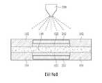
在下文中,將參照圖5a至圖5h描述根據本揭露實施例的製造膜電極組合100的方法。Hereinafter, a method of manufacturing the
圖5a至圖5h是示出根據本揭露實施例的製造膜電極組合100的製程的視圖。5a to 5h are views showing the manufacturing process of the
首先參照圖5a,在電解質膜110的第一表面111上方形成第一電極121。Referring first to FIG. 5a, a
形成第一電極121的方法不受特別限制。根據本揭露的實施例,第一電極121可使用塗佈方法或轉移方法形成。本揭露所屬技術中眾所習知的氧化電極材料及還原電極材料中的至少一者可用作第一電極121的材料。The method of forming the
在形成第一電極121的步驟中,電解質膜110可由支撐基板190支撐。支撐基板190的種類不受特別限制。任何能夠支撐電解質膜110的材料皆可用於支撐基板190。舉例而言,塑膠膜可用作支撐基板190。根據本揭露的實施例,聚對苯二甲酸乙二醇酯(PET)膜可用作支撐基板190。In the step of forming the
參照圖5b,在第一電極121上方設置第一鈍化層211。Referring to FIG. 5b, a
第一鈍化層211保護第一電極121。第一鈍化層211可在塗佈之後被移除以形成第一子墊圈131,或者可保持貼附至第一電極,直至形成第二子墊圈132,且然後在形成第二子墊圈132之後與第二鈍化層212一起被移除。因此,第一鈍化層211由能夠在剝離製程期間使對第一電極121的損壞最小化的材料製成。The
舉例而言,選自由聚對苯二甲酸乙二醇酯(PET)、聚醯亞胺(PI)、四氟乙烯、聚乙烯(PE)、橡膠及矽酮組成的群組中的至少一者可用於第一鈍化層211。For example, at least one selected from the group consisting of polyethylene terephthalate (PET), polyimide (PI), tetrafluoroethylene, polyethylene (PE), rubber and silicone It can be used for the
第一鈍化層211可具有1微米至50微米的厚度。The
此外,參照圖5b,第一鈍化層211可具有較第一電極121小的面積,並且可設置在第一電極121的區內。更具體而言,第一鈍化層211可設置在第一電極121的邊緣內部。因此,第一子墊圈131可設置在第一電極121的邊緣上方。In addition, referring to FIG. 5b, the
參照圖5c,藉由塗佈第一液體材料,在電解質膜110的第一表面111上方形成第一子墊圈131。5c, by coating the first liquid material, a
用於形成第一子墊圈131的第一液體材料可包括可交聯或可固化的彈性材料。The first liquid material used to form the
具體而言,第一子墊圈131可包括選自由聚對苯二甲酸乙二醇酯(PET)、聚醯胺、四氟乙烯/六氟丙烯(FEP)、氟橡膠、矽酮橡膠、烴系彈性體(EPDM、EPR等)及聚胺基甲酸酯組成的群組中的至少一者。因此,第一液體材料可為包括選自由聚對苯二甲酸乙二醇酯(PET)、聚醯胺、四氟乙烯/六氟丙烯(FEP)、氟橡膠、矽酮橡膠、烴系彈性體(EPDM、EPR等)及聚胺基甲酸酯組成的群組中的任一者的溶解或分散在溶劑中的材料。如此一來,第一液體材料可包括聚合物組分。Specifically, the
根據本揭露的實施例,第一子墊圈131可藉由使用液體材料的直接塗佈方法形成。According to an embodiment of the present disclosure, the
具體而言,選自由各自使用液體材料的噴塗、刮刀式塗佈及狹縫模具塗佈組成的群組中的任一者可用於形成第一子墊圈131。舉例而言,第一子墊圈131可藉由噴塗形成。Specifically, any one selected from the group consisting of spray coating, knife coating, and slit die coating each using a liquid material can be used to form the
圖5c示出藉由噴塗形成第一子墊圈131的方法。如上所述,根據本揭露的實施例,使用液體材料的直接塗佈方法可用作形成第一子墊圈131的塗佈方法。參照圖5c,使用噴塗設備250來執行噴塗。FIG. 5c shows a method of forming the
在塗佈後,將第一液體材料乾燥並交聯或固化,由此完成第一子墊圈131。After coating, the first liquid material is dried and cross-linked or cured, thereby completing the
在形成第一子墊圈131的步驟中,第一子墊圈131可在塗佈後放置10秒至600秒。如此一來,用於形成第一子墊圈131的第一液體材料可被乾燥,並且包括在第一液體材料中的聚合物組分可被交聯或固化。In the step of forming the
此外,在形成第一子墊圈131的步驟中,在使用第一液體材料塗佈之後,可在40℃至150℃的溫度下對第一子墊圈131進行加熱。由於所述加熱,包括在第一液體材料中的聚合物組分的熱交聯或熱固化可被加速,使得完成第一子墊圈131。In addition, in the step of forming the
根據本揭露的實施例,在形成第一子墊圈131的步驟中,在使用第一液體材料塗佈之後,可使用熱空氣對第一子墊圈131進行3秒至300秒的熱處理。According to an embodiment of the present disclosure, in the step of forming the
參照圖5d,將電解質膜110與支撐基板190分離,且然後將電解質膜110上下顛倒,使得電解質膜110的第二表面112面朝上。5d, the
參照圖5e,在電解質膜110的第二表面112上方形成第二電極122。Referring to FIG. 5e, a
第二電極122可使用與第一電極121相同的方法形成。根據本揭露的實施例,第二電極122可使用塗佈方法或轉移方法形成。在第一電極121為氧化電極的情形中,第二電極122為還原電極,並且在第一電極121為還原電極的情形中,第二電極122為氧化電極。本揭露所屬技術中眾所習知的還原電極材料及氧化電極材料中的至少一者可用作第二電極122的材料。The
參照圖5f,在第二電極122上方設置第二鈍化層212。Referring to FIG. 5f, a
第二鈍化層212保護第二電極122。在塗佈之後,移除第二鈍化層212以形成第二子墊圈132。因此,第二鈍化層212由能夠在剝離製程期間使對第二電極122的損壞最小化的材料製成。The
第二鈍化層212可由與第一鈍化層211相同的材料製成。The
舉例而言,選自由聚對苯二甲酸乙二醇酯(PET)、聚醯亞胺(PI)、四氟乙烯、聚乙烯(PE)、橡膠及矽酮組成的群組中的至少一者可用於第二鈍化層212。第一鈍化層122可具有1微米至50微米的厚度。For example, at least one selected from the group consisting of polyethylene terephthalate (PET), polyimide (PI), tetrafluoroethylene, polyethylene (PE), rubber and silicone It can be used for the
參照圖5f,第二鈍化層212可具有較第二電極122小的面積,並且可設置在第二電極122的區內。更具體而言,第二鈍化層212可設置在第二電極122的邊緣內部。因此,第二子墊圈132可設置在第二電極122的邊緣上方。Referring to FIG. 5f, the
參照圖5g,藉由塗佈第二液體材料,在電解質膜110的第二表面112上方形成第二子墊圈132。5g, by coating a second liquid material, a
形成第二子墊圈132的第二液體材料可與形成第一子墊圈131的第一液體材料相同或不同。The second liquid material forming the
根據本揭露的實施例,第一液體材料與第二液體材料可具有相同的組成。According to the embodiment of the present disclosure, the first liquid material and the second liquid material may have the same composition.
另一方面,取決於施加液體材料的區或液體材料的使用目的,可將不同的添加劑添加至第一液體材料及第二液體材料,由此所述第一液體材料及第二液體材料的組成可彼此不同。因此,第一子墊圈131及第二子墊圈132可具有不同的功能。On the other hand, depending on the area where the liquid material is applied or the purpose of use of the liquid material, different additives can be added to the first liquid material and the second liquid material, thereby the composition of the first liquid material and the second liquid material Can be different from each other. Therefore, the
形成第二子墊圈132的第二液體材料可為可交聯或可固化的彈性材料。The second liquid material forming the
具體而言,第二子墊圈132可包括選自由聚對苯二甲酸乙二醇酯(PET)、聚醯胺、四氟乙烯/六氟丙烯(FEP)、氟橡膠、矽酮橡膠、烴系彈性體(EPDM、EPR等)及聚胺基甲酸酯組成的群組中的至少一者。換言之,第二液體材料可為包括選自由聚對苯二甲酸乙二醇酯(PET)、聚醯胺、四氟乙烯/六氟丙烯(FEP)、氟橡膠、矽酮橡膠、烴系彈性體(EPDM、EPR等)及聚胺基甲酸酯組成的群組中的任一者的溶解或分散在溶劑中的材料。如此一來,第二液體材料可包括聚合物組分。根據本揭露的實施例,第二子墊圈132可使用液體材料藉由直接塗佈方法形成。Specifically, the
具體而言,選自由各自使用液體材料的噴塗、刮刀式塗佈及狹縫模具塗佈組成的群組中的任一者可用作形成第二子墊圈132的塗佈方法。舉例而言,第二子墊圈132可藉由噴塗形成。Specifically, any one selected from the group consisting of spray coating, knife coating, and slit die coating each using a liquid material can be used as a coating method for forming the
圖5g示出藉由噴塗形成第二子墊圈132的方法。如上所述,根據本揭露的實施例,使用液體材料的直接塗佈方法可用於形成第二子墊圈132。通常,可使用噴塗。FIG. 5g shows a method of forming the
在塗佈後,將第二液體材料乾燥並交聯或固化,由此完成第二子墊圈132。After coating, the second liquid material is dried and cross-linked or cured, thereby completing the
在形成第二子墊圈132的步驟中,第二子墊圈132可在塗佈後放置10秒至600秒。因此,用於形成第二子墊圈132的第二液體材料可被乾燥,並且包括在第二液體材料中的聚合物組分可被交聯或固化。In the step of forming the
此外,在形成第二子墊圈132的步驟中,在使用第二液體材料塗佈之後,可在40℃至150℃的溫度下對第二子墊圈131進行加熱。由於所述加熱,包括在第二液體材料中的聚合物組分的熱交聯或熱固化可被加速,由此完成第二子墊圈131。In addition, in the step of forming the
根據本揭露的實施例,在形成第二子墊圈131的步驟中,在使用第二液體材料塗佈之後,可使用熱空氣對第二子墊圈131進行3秒至300秒的熱處理。According to an embodiment of the present disclosure, in the step of forming the
第一子墊圈131及第二子墊圈132可同時或個別加熱。The
然而,本揭露並非僅限於此。依據材料,可執行加熱,或者亦可不執行加熱。However, this disclosure is not limited to this. Depending on the material, heating may be performed, or heating may not be performed.
參照圖5h,移除第一鈍化層211及第二鈍化層212。當移除第一鈍化層211及第二鈍化層212時,由保留在第一鈍化層211上的第一液體材料製成的塗層及由保留在第二鈍化層212上的第二液體材料製成的塗層亦被移除。5h, the
由於移除了第一鈍化層211及第二鈍化層212,因此第一電極121及第二電極122被暴露出,並且完成根據本揭露實施例的膜電極組合100。參照圖5h,暴露出第一電極121的與電解質膜110相對的表面,並且暴露出第二電極122的與電解質膜110相對的表面。Since the
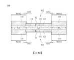
圖6是根據本揭露另一實施例的膜電極組合200的剖視圖。FIG. 6 is a cross-sectional view of a
圖6所示的膜電極組合200與圖4A及圖4B所示的膜電極組合的不同之處在於:電解質膜110的整個邊緣被第一子墊圈131及第二子墊圈132包圍。The difference between the
相較於圖4A及圖4B所示的其中電解質膜110具有與第一子墊圈131或第二子墊圈132相同大小的膜電極組合100,圖6所示的子墊圈積體膜電極組合200的電解質膜110的邊緣可被更穩定地保護,並且可以較少的量使用通常昂貴的電解質膜110,此使得本實施例更經濟。Compared with the
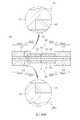
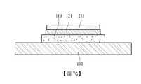
圖7a至圖7h是示出根據本揭露另一實施例的製造膜電極組合200的製程的視圖。7a to 7h are views showing a process of manufacturing a
根據本揭露另一實施例的製造膜電極組合200的方法更包括在形成第一子墊圈131之前切割電解質膜110的至少一部分。The method of manufacturing the
在下文中,將參照圖7a至圖7h描述根據本揭露另一實施例的製造膜電極組合200的方法。Hereinafter, a method of manufacturing a
首先參照圖7a,在電解質膜110的第一表面111上方形成第一電極121。形成第一電極121的方法不受特別限制。第一電極121可使用塗佈或轉移方法形成。Referring first to FIG. 7a, a
參照圖7b,切割電解質膜110的邊緣。此時,可使用刀具260或尖頂模具(pinnacle die)。因此,電解質膜110具有較支撐基板190小的面積。Referring to FIG. 7b, the edge of the
參照圖7c,在第一電極121上方設置第一鈍化層211。當執行後續塗佈製程時,第一鈍化層211保護第一電極121。Referring to FIG. 7c, a
參照圖7d,藉由塗佈第一液體材料,在電解質膜110的第一表面111上方形成第一子墊圈131。第一子墊圈131完全包圍電解質膜110的第一表面111及側表面。Referring to FIG. 7d, by coating a first liquid material, a
參照圖7d,可藉由噴塗形成第一子墊圈131,噴塗為一種使用液體材料的直接塗佈。在塗佈後,將第一液體材料乾燥並交聯或固化。Referring to FIG. 7d, the
參照圖7e,將電解質膜110與支撐基板190分離,且然後將電解質膜110上下顛倒,使得電解質膜110的第二表面112面朝上。7e, the
參照圖7f,在電解質膜110的第二表面112上方形成第二電極122,並且在第二電極122上方設置第二鈍化層212。第二鈍化層212保護第二電極122。Referring to FIG. 7f, a
參照圖7g,藉由塗佈第二液體材料,在電解質膜110的第二表面112上方及第一子墊圈131上方形成第二子墊圈132。7g, by coating a second liquid material, a
形成第二子墊圈132的第二液體材料可與形成第一子墊圈131的第一液體材料相同或不同。參照圖7g,第二子墊圈132可藉由噴塗形成。因此,根據本揭露的實施例,使用液體材料的直接塗佈方法可用作形成第二子墊圈132的塗佈方法。舉例而言,可使用噴塗。The second liquid material forming the
在塗佈後,可將第二液體材料乾燥並交聯或固化。After coating, the second liquid material can be dried and crosslinked or cured.
參照圖7h,移除第一鈍化層211及第二鈍化層212。當移除第一鈍化層211及第二鈍化層212時,由保留在第一鈍化層211上的第一液體材料製成的塗層及由保留在第二鈍化層212上的第二液體材料製成的塗層亦被移除。移除第一鈍化層211及第二鈍化層212會暴露出第一電極121及第二電極122,由此完成根據本揭露另一實施例的膜電極組合200。7h, the
由於藉由塗佈方法形成的子墊圈131及132的厚度是以可變方式可調節的,並且子墊圈131及132是藉由使用液體的塗佈方法製造的,因此可形成子墊圈131及132而不會導致氣隙,所述氣隙是由於當層疊傳統的膜型子墊圈時與電極層的厚度對應的台階引起的。此外,可將子墊圈131及132製造成扁平形狀,藉此在組裝氣體擴散層(gas diffusion layer,GDL)時達成容易的可加工性。Since the thickness of the
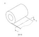
圖8是卷狀捲繞的膜電極組合的立體圖。Fig. 8 is a perspective view of a membrane electrode assembly wound in a roll shape.
如圖8所示,根據本揭露實施例的膜電極組合100及200中的每一者可卷狀捲繞。沿著圖8的線I-I’截取的剖視圖可如圖4A、圖4B或圖6所示。As shown in FIG. 8, each of the
根據本揭露的實施例在電解質膜110上方直接塗佈用於子墊圈的材料使得可以卷對卷(roll-to-roll)方式製造膜電極組合100及200。因此,大規模生產變得可行。According to the embodiment of the present disclosure, the material for the sub-gasket is directly coated on the
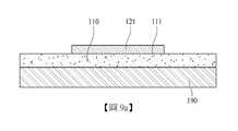
在下文中,將參照圖9a至圖9f描述根據本揭露另一實施例的製造膜電極組合的方法。Hereinafter, a method of manufacturing a membrane electrode assembly according to another embodiment of the present disclosure will be described with reference to FIGS. 9a to 9f.
參照圖9a,在電解質膜110的第一表面111上方形成第一電極121。Referring to FIG. 9 a, a
當形成第一電極121時,電解質膜110可由支撐基板190支撐。When the
參照圖9b,藉由塗佈第一液體材料,在電解質膜110的第一表面111上方形成第一子墊圈131。9b, by coating the first liquid material, a
形成第一子墊圈131的第一液體材料可為可交聯或可固化的彈性材料。The first liquid material forming the
根據本揭露的另一實施例,第一子墊圈131可藉由在無任何鈍化層的情況下,在電解質膜110上方在第一電極121周圍直接塗佈/印刷用於第一子墊圈131的第一液體材料而形成。舉例而言,第一液體材料可在無任何鈍化層的情況下藉由3D列印機或局部塗佈設備直接塗佈/印刷在第一電極121周圍,並且被交聯。因此,第一子墊圈131選擇性地形成在電解質膜110上方。According to another embodiment of the present disclosure, the
圖9b示出使用3D列印機350執行直接塗佈的方法。FIG. 9b shows a method of performing direct coating using a
參照圖9c,在塗佈/印刷之後,將第一液體材料乾燥並交聯或固化,由此完成第一子墊圈131。9c, after coating/printing, the first liquid material is dried and cross-linked or cured, thereby completing the
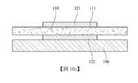
參照圖9d,將電解質膜110與支撐基板190分離,且然後將電解質膜110上下顛倒,使得電解質膜110的第二表面112面朝上。隨後,在電解質膜110的第二表面112上方形成第二電極122。9d, the
第二電極122可使用與第一電極121相同的方法形成。根據本揭露的實施例,第二電極122可使用塗佈或轉移方法形成。在第一電極121為氧化電極的情形中,第二電極122為還原電極,並且在第一電極121為還原電極的情形中,第二電極122為氧化電極。The
參照圖9e,藉由塗佈第二液體材料,在電解質膜110的第二表面112上方形成第二子墊圈132。9e, by coating the second liquid material, a
形成第二子墊圈132的第二液體材料可為可交聯或可固化的彈性材料。形成第二子墊圈132的第二液體材料可與形成第一子墊圈131的第一液體材料相同或不同。The second liquid material forming the
根據本揭露的另一實施例,第二子墊圈132可藉由在無鈍化層的情況下,在電解質膜110上方在第二電極122周圍直接塗佈/印刷用於第二子墊圈132的第二液體材料而形成。舉例而言,第二液體材料可在無鈍化層的情況下使用3D列印機或局部塗佈設備直接塗佈/印刷在第二電極122周圍,且然後交聯。因此,第二子墊圈132選擇性地形成在電解質膜110上方。According to another embodiment of the present disclosure, the
圖9e示出使用3D列印機350執行直接塗佈的方法。FIG. 9e shows a method of performing direct coating using a
參照圖9f,在塗佈/印刷之後,將第二液體材料乾燥及交聯或固化,由此完成第二子墊圈132。因此,製造成根據本揭露另一實施例的膜電極組合。9f, after coating/printing, the second liquid material is dried and crosslinked or cured, thereby completing the
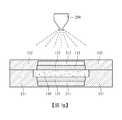
圖10a至圖10h是示出根據比較例1的製造膜電極組合的製程的視圖。10a to 10h are views showing a process of manufacturing a membrane electrode assembly according to Comparative Example 1. FIG.
根據比較例1的製造膜電極組合的方法與本揭露的實施例的不同之處在於:使用了包括已經形成在電解質膜110上的第一電極121及第二電極122的觸媒塗佈膜(catalyst coated membrane,CCM)。The method of manufacturing a membrane electrode combination according to Comparative Example 1 is different from the embodiment of the present disclosure in that a catalyst coating film including the
具體而言,參照圖10a,在支撐基板190上設置包括已經形成在電解質膜110上的第一電極121及第二電極122的觸媒塗佈膜(CCM)。Specifically, referring to FIG. 10 a, a catalyst coating film (CCM) including a
參照圖10b,在CCM的第一電極121上設置第一鈍化層211。10b, a
參照圖10c,藉由塗佈第一液體材料,在電解質膜110的第一表面111上形成第一子墊圈131。10c, by coating the first liquid material, a
參照圖10d,移除第一鈍化層211。Referring to FIG. 10d, the
參照圖10e,將電解質膜110上下顛倒,使得電解質膜110的第二表面及第二電極122面朝上。10e, the
參照圖10f,在第二電極122上設置第二鈍化層212。第二鈍化層212在隨後的塗佈製程期間保護第二電極122。Referring to FIG. 10f, a
參照圖10g,藉由塗佈第二液體材料,在電解質膜110的第二表面上形成第二子墊圈132。10g, by coating a second liquid material, a
參照圖10h,移除第二鈍化層212。Referring to FIG. 10h, the
如圖10a至圖10h所示,當使用觸媒塗佈膜(CCM)並且藉由噴塗製造子墊圈積體膜電極組合時,由於電極121及122的厚度,CCM的電解質膜110(具體而言是其非主動區域)無法被支撐基板190充分支撐,由此膜電極組合可能捲曲。As shown in Figures 10a to 10h, when a catalyst coating film (CCM) is used and the sub-gasket integrated membrane electrode assembly is manufactured by spraying, due to the thickness of the
參照圖10a至圖10d可見,電解質膜110的非主動區域不與支撐基板190緊密接觸,而是與支撐基板190間隔開。由於此種間隔,可能在電解質膜110的非主動區域處引起捲曲,且因此在所得的膜電極組合中可能發生捲曲。10a to 10d, it can be seen that the inactive area of the
相對於使用圖5a至圖5h所示的根據本揭露實施例的方法製造的膜電極組合100的100個樣品(實例1)及使用圖10a至圖10h所示的方法製造的膜電極組合的100個樣品(比較例1),計算每個樣品的平均捲曲數及良率。結果示於表1中。Compared to 100 samples (Example 1) of the
每個樣品的平均捲曲數是指100個樣品捲曲數的平均值,且良率是指無缺陷的產品的比率。[表1]
參照表1可見,在根據本揭露的實施例製造膜電極組合100的情形中,缺陷率低,並且每個樣品的平均捲曲數小。Referring to Table 1, it can be seen that in the case of manufacturing the
圖11是根據比較例2的膜電極組合的剖視圖。FIG. 11 is a cross-sectional view of a membrane electrode assembly according to Comparative Example 2. FIG.
在圖11的膜電極組合中,貼附有膜型子墊圈161及162。In the membrane electrode assembly of FIG. 11, membrane-shaped
在膜型子墊圈161及162的情形中,由於子墊圈161及162的厚度是基於膜厚度確定的,因此相較於子墊圈131及132藉由直接塗佈方法形成的情形,不容易進行厚度調節。In the case of the film-
當使用膜型子墊圈161及162時,子墊圈161及162將具有對應於電極121及122的厚度的台階,並且由於該些台階,可能在子墊圈161及162與電極121及122之間導致氣隙290。圖11示出由電極121及122以及膜型子墊圈161及162包圍的氣隙290。此種氣隙290導致氣體洩漏,藉此使膜電極組合的品質劣化。When the film-
假定氣隙290具有等腰直三角柱的形狀,並且分別在四邊形電極121及122的邊緣四周形成,當使用膜型子墊圈161及162時生成的每個氣隙的體積可藉由以下方程式計算。* V (cm3) = T2× (W + L)其中V是每個氣隙290的體積,T是電極121及122中的每一者的厚度,W是電極121及122中的每一者的寬度,且L是電極121及122中的每一者的長度。Assuming that the
與此相反,根據本揭露的實施例,子墊圈131及132藉由直接塗佈方法形成,由此子墊圈131及132的厚度可以各種方式進行調節。另外,根據本揭露的實施例,由於子墊圈131及132藉由塗佈液體材料來製造,因此子墊圈131及132將無台階,或者即使其具有台階,所述台階的高度亦將小至電極121及122的厚度T1及T2的0.5倍或小於0.5倍,更佳地0.2倍或小於0.2倍(即,每個子墊圈的上表面實質上是平坦的)。因此,根據本揭露,可改善後續製程(例如,氣體擴散層GDL形成/組裝製程)中的可加工性,並且可避免或最小化導致氣體洩漏的任何可能的氣隙(為使用膜型子墊圈時形成的氣隙的體積的0.5倍或小於0.5倍,更佳地為0.2倍或小於0.2倍)。In contrast, according to the embodiment of the present disclosure, the
亦即,根據本揭露的實施例,在第一子墊圈131與第一電極121之間無氣隙,或者即使在第一子墊圈131與第一電極121之間有第一氣隙,第一氣隙的體積亦將滿足以下方程式1,並且在第二子墊圈132與第二電極122之間無氣隙,或者即使在第二子墊圈132與第二電極122之間存在第二氣隙,第二氣隙的體積亦將滿足以下方程式2。*方程式1: V1≤ 0.5 × T12× (W1+ L1)*方程式2: V2≤ 0.5 × T22× (W2+ L2)其中V1及V2分別是第一氣隙及第二氣隙的體積,T1及T2分別是第一電極121及第二電極122的厚度,W1及W2分別是第一電極121及第二電極122的寬度,且L1及L2分別是第一電極121及第二電極122的長度。That is, according to the embodiment of the present disclosure, there is no air gap between the
圖12a至圖12c是膜電極組合的照片。Figures 12a to 12c are photographs of the membrane electrode assembly.
具體而言,圖12a是使用圖5a至圖5h所示的方法製造的膜電極組合100的照片,圖12b是使用圖10a至圖10h所示的方法製造的膜電極組合(比較例1)的照片,並且圖12c是上面貼附有膜型子墊圈的膜電極組合(比較例2)的照片。Specifically, FIG. 12a is a photo of the
參照圖12b可見,根據比較例1製造的膜電極組合具有多個捲曲。Referring to FIG. 12b, it can be seen that the membrane electrode assembly manufactured according to Comparative Example 1 has multiple crimps.
如圖12c所示,在根據比較例2製造的膜電極組合內部導致氣隙。As shown in FIG. 12c, an air gap is caused inside the membrane electrode assembly manufactured according to Comparative Example 2.
與此相反,如圖12a所示,根據本揭露實施例製造的膜電極組合既無捲曲亦無氣隙。In contrast, as shown in FIG. 12a, the membrane electrode assembly manufactured according to the embodiment of the present disclosure has neither curl nor air gap.
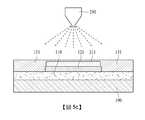
圖13是根據本揭露實施例的燃料電池300的剖視圖。FIG. 13 is a cross-sectional view of a
根據本揭露實施例的燃料電池300包括上述膜電極組合100、位於膜電極組合100上方的氣體擴散層140、以及位於氣體擴散層140上方的隔板150。The
膜電極組合100包括電解質膜110、設置在電解質膜110的第一表面上方的第一電極121及第一子墊圈131、以及設置在電解質膜110的第二表面上方的第二電極122及第二子墊圈132。The
氣體擴散層140及隔板150中的每一者可分別設置在膜電極組合100的兩側上方。已經描述了氣體擴散層140及隔板150,且對其將不再予以贅述。Each of the
參照圖13,根據本揭露另一實施例的燃料電池300可包括第一墊圈171及第二墊圈172。Referring to FIG. 13, a
第一墊圈171及第二墊圈172設置在膜電極組合100與隔板150之間,以不透氣地密封限定在膜電極組合100與隔板150之間的空間。參照圖13,氣體擴散層140可設置在由第一子墊圈131及第一墊圈171限定的空間以及由第二子墊圈132及第二墊圈172限定的空間中。The
圖13示出僅形成在第一電極121及第二電極122的被暴露出的部分上的氣體擴散層140。然而,本揭露並非僅限於此。氣體擴散層140可延伸以覆蓋第一子墊圈131及第二子墊圈132中的每一者的至少一部分。FIG. 13 shows the
提供上述實施例是為了幫助理解本揭露,並且本揭露的權利範圍並非受限於此。本揭露的權利範圍由以下申請專利範圍限定。The above-mentioned embodiments are provided to help understand the present disclosure, and the scope of rights of the present disclosure is not limited thereto. The scope of rights of this disclosure is defined by the scope of the following patent applications.
10:電解質膜21:氧化電極/第一電極22:還原電極/第二電極31、32:子墊圈41、42:氣體擴散層51、52:墊圈61、62:隔板100:膜電極組合110:電解質膜111:第一表面112:第二表面121:第一電極122:第二電極131:第一子墊圈132:第二子墊圈140:氣體擴散層150:隔板161、162:子墊圈/膜型子墊圈171:第一墊圈172:第二墊圈190:支撐基板200:膜電極組合211:第一鈍化層212:第二鈍化層250:噴塗設備260:刀具290:氣隙300:燃料電池350:3D列印機AA:主動區域H1、H2:高度I-I’:線NA:非主動區域NOA1:第一非重疊區域NOA2:第二非重疊區域OA1:第一重疊區域OA2:第二重疊區域T1、T2:厚度W1:寬度/第一窗口W2:寬度/第二窗口10: Electrolyte membrane21: Oxidation electrode/first electrode22: reduction electrode/
被包括在內以幫助理解本揭露、並且被併入本說明書中並構成本說明書的一部分的附圖示出本揭露的實施例,並且用於與本揭露的詳細描述一起闡釋本揭露的原理。圖1是示出燃料電池的操作的示意圖。圖2是燃料電池的分解立體圖。圖3是根據本揭露實施例的膜電極組合的分解立體圖。圖4a是根據本揭露實施例的膜電極組合的剖視圖。圖4b是根據本揭露另一實施例的膜電極組合的剖視圖。圖5a至圖5h是示出根據本揭露實施例的製造膜電極組合的製程的視圖。圖6是根據本揭露另一實施例的膜電極組合的剖視圖。圖7a至圖7h是示出根據本揭露另一實施例的製造膜電極組合的製程的視圖。圖8是卷狀捲繞的膜電極組合的立體圖。圖9a至圖9f是示出根據本揭露實施例的製造膜電極組合的製程的視圖。圖10a至圖10h是示出根據比較例1的製造膜電極組合的製程的視圖。圖11是根據比較例2的膜電極組合的剖視圖。圖12a至圖12c是膜電極組合的照片。圖13是根據本揭露另一實施例的燃料電池的剖視圖。The accompanying drawings, which are included to help the understanding of the present disclosure, are incorporated into the present specification and constitute a part of the present specification, illustrate the embodiments of the present disclosure, and are used to explain the principle of the present disclosure together with the detailed description of the present disclosure.Fig. 1 is a schematic diagram showing the operation of a fuel cell.Fig. 2 is an exploded perspective view of the fuel cell.Fig. 3 is an exploded perspective view of the membrane electrode assembly according to an embodiment of the present disclosure.Fig. 4a is a cross-sectional view of a membrane electrode assembly according to an embodiment of the disclosure.4b is a cross-sectional view of a membrane electrode assembly according to another embodiment of the disclosure.5a to 5h are views showing a process of manufacturing a membrane electrode assembly according to an embodiment of the present disclosure.FIG. 6 is a cross-sectional view of a membrane electrode assembly according to another embodiment of the disclosure.7a to 7h are views showing a process of manufacturing a membrane electrode assembly according to another embodiment of the present disclosure.Fig. 8 is a perspective view of a membrane electrode assembly wound in a roll shape.9a to 9f are views showing a process of manufacturing a membrane electrode assembly according to an embodiment of the present disclosure.10a to 10h are views showing a process of manufacturing a membrane electrode assembly according to Comparative Example 1. FIG.FIG. 11 is a cross-sectional view of a membrane electrode assembly according to Comparative Example 2. FIG.Figures 12a to 12c are photographs of the membrane electrode assembly.FIG. 13 is a cross-sectional view of a fuel cell according to another embodiment of the present disclosure.
10:電解質膜10: Electrolyte membrane
100:膜電極組合100: Membrane electrode combination
110:電解質膜110: Electrolyte membrane
111:第一表面111: first surface
112:第二表面112: second surface
121:第一電極121: first electrode
122:第二電極122: second electrode
131:第一子墊圈131: The first sub washer
132:第二子墊圈132: The second sub washer
AA:主動區域AA: active area
NA:非主動區域NA: Inactive area
NOA1:第一非重疊區域NOA1: the first non-overlapping area
NOA2:第二非重疊區域NOA2: second non-overlapping area
OA1:第一重疊區域OA1: The first overlap area
OA2:第二重疊區域OA2: second overlap area
T1、T2:厚度T1, T2: thickness
W1:寬度/第一窗口W1: width/first window
W2:寬度/第二窗口W2: width/second window
Claims (19)
Translated fromChineseApplications Claiming Priority (4)
| Application Number | Priority Date | Filing Date | Title |
|---|---|---|---|
| KR20190082107 | 2019-07-08 | ||
| KR10-2019-0082107 | 2019-07-08 | ||
| KR10-2019-0148939 | 2019-11-19 | ||
| KR1020190148939AKR102392262B1 (en) | 2019-07-08 | 2019-11-19 | Membrane-electrode assembly, method for manufacturing the same, and fuel cell comprising the same |
Publications (2)
| Publication Number | Publication Date |
|---|---|
| TW202109957Atrue TW202109957A (en) | 2021-03-01 |
| TWI757775B TWI757775B (en) | 2022-03-11 |
Family
ID=74115049
Family Applications (1)
| Application Number | Title | Priority Date | Filing Date |
|---|---|---|---|
| TW109121779ATWI757775B (en) | 2019-07-08 | 2020-06-29 | Membrane-electrode assembly, method for manufacturing the same, and fuel cell comprising the same |
Country Status (7)
| Country | Link |
|---|---|
| US (1) | US20220181652A1 (en) |
| EP (1) | EP3998661A4 (en) |
| JP (2) | JP7381610B2 (en) |
| KR (1) | KR102458461B1 (en) |
| CN (2) | CN117936831A (en) |
| TW (1) | TWI757775B (en) |
| WO (1) | WO2021006498A1 (en) |
Families Citing this family (2)
| Publication number | Priority date | Publication date | Assignee | Title |
|---|---|---|---|---|
| CN119725357A (en)* | 2023-09-28 | 2025-03-28 | 宁德时代新能源科技股份有限公司 | Positive electrode sheet, battery and electric device |
| CN118888977B (en)* | 2024-10-08 | 2025-02-21 | 宁德时代新能源科技股份有限公司 | Battery cell and manufacturing method thereof, battery device and power-consuming device |
Family Cites Families (19)
| Publication number | Priority date | Publication date | Assignee | Title |
|---|---|---|---|---|
| JPH10199551A (en)* | 1997-01-06 | 1998-07-31 | Honda Motor Co Ltd | Fuel cell structure and method of manufacturing the same |
| KR100448168B1 (en)* | 2001-12-27 | 2004-09-10 | 현대자동차주식회사 | A preparing method of Membrane-Electrode-Gasket Assembly for fuel cell |
| US20060078781A1 (en)* | 2004-10-08 | 2006-04-13 | 3M Innovative Properties Company | Curable subgasket for a membrane electrode assembly |
| US8426078B2 (en)* | 2007-12-21 | 2013-04-23 | 3M Innovative Properties Company | Manufacturing of fuel cell membrane electrode assemblies incorporating photocurable cationic crosslinkable resin gasket |
| JP4998748B2 (en) | 2008-09-19 | 2012-08-15 | トヨタ自動車株式会社 | Method for producing polymer electrolyte fuel cell, and polymer electrolyte fuel cell produced by the method |
| JP5552766B2 (en)* | 2009-07-21 | 2014-07-16 | 大日本印刷株式会社 | Edge-sealed catalyst layer-electrolyte membrane laminate, electrode-electrolyte membrane assembly, polymer electrolyte fuel cell, catalyst layer-electrolyte membrane laminate production method, and edge-sealed catalyst layer-electrolyte membrane laminate production method |
| KR101243704B1 (en)* | 2010-12-07 | 2013-03-13 | 현대자동차주식회사 | Manufacturing method of fuel cell stack |
| JP2013062169A (en)* | 2011-09-14 | 2013-04-04 | Honda Motor Co Ltd | Method of manufacturing membrane electrode assembly for fuel cell |
| KR101350186B1 (en)* | 2011-09-27 | 2014-01-09 | 기아자동차주식회사 | The sub-gasket adhesion method for fuel cell membrane electrode assembly production using ultrasonic vibration |
| US9076998B2 (en)* | 2012-09-12 | 2015-07-07 | GM Global Technology Operations LLC | Fuel-cell membrane-subgasket assemblies comprising coated subgaskets, and fuel-cell assemblies and fuel-cell stacks comprising the fuel-cell membrane subgasket assemblies |
| KR101684550B1 (en)* | 2015-07-29 | 2016-12-08 | 현대자동차 주식회사 | Device and method for manufacturing membrane-electrode assembly of fuel cell |
| KR101703617B1 (en)* | 2015-09-03 | 2017-02-07 | 현대자동차 주식회사 | Heat treatment device of mea for fuel cell |
| KR102512283B1 (en)* | 2015-10-27 | 2023-03-22 | 범한퓨얼셀 주식회사 | Membrane-electrode assembly and preparation method thereof |
| KR101776755B1 (en)* | 2016-03-04 | 2017-09-08 | 현대자동차 주식회사 | Manufacturing device of fuel cell component and manufacturing method |
| KR102518684B1 (en)* | 2016-12-13 | 2023-04-05 | 현대자동차주식회사 | Membrane electrode assembly for fue cell and manufacturing method thereof |
| KR20180126708A (en)* | 2017-05-18 | 2018-11-28 | 율촌화학 주식회사 | Gasket-integrated membrane electrode assembly and preparation method of the same |
| KR102163539B1 (en)* | 2017-09-29 | 2020-10-08 | 코오롱인더스트리 주식회사 | Membrane-electrode assembly, method for manufacturing the same, and fuel cell stack comprising the same |
| KR102673000B1 (en)* | 2018-07-30 | 2024-06-05 | 현대자동차주식회사 | Method for preparing flat―type membrane electrode assembly for fuel cell and flat―type membrane electrode assembly for fuel cell prepared using the same |
| KR102750645B1 (en)* | 2018-12-28 | 2025-01-06 | 현대자동차주식회사 | Membrane Electrode Assembly For Fuel Cell And Manufacturing Method Thereof |
- 2020
- 2020-06-18WOPCT/KR2020/007886patent/WO2021006498A1/ennot_activeCeased
- 2020-06-18EPEP20836285.5Apatent/EP3998661A4/enactivePending
- 2020-06-18CNCN202410142036.7Apatent/CN117936831A/enactivePending
- 2020-06-18CNCN202080049245.7Apatent/CN114556644B/enactiveActive
- 2020-06-18JPJP2021570248Apatent/JP7381610B2/enactiveActive
- 2020-06-18USUS17/601,919patent/US20220181652A1/enactivePending
- 2020-06-29TWTW109121779Apatent/TWI757775B/enactive
- 2022
- 2022-01-24KRKR1020220009894Apatent/KR102458461B1/enactiveActive
- 2023
- 2023-01-31JPJP2023013332Apatent/JP7551796B2/enactiveActive
Also Published As
| Publication number | Publication date |
|---|---|
| CN117936831A (en) | 2024-04-26 |
| JP2022534244A (en) | 2022-07-28 |
| US20220181652A1 (en) | 2022-06-09 |
| WO2021006498A1 (en) | 2021-01-14 |
| KR102458461B1 (en) | 2022-10-26 |
| KR20220016261A (en) | 2022-02-08 |
| TWI757775B (en) | 2022-03-11 |
| JP7551796B2 (en) | 2024-09-17 |
| JP7381610B2 (en) | 2023-11-15 |
| CN114556644B (en) | 2024-03-01 |
| EP3998661A1 (en) | 2022-05-18 |
| CN114556644A (en) | 2022-05-27 |
| JP2023055831A (en) | 2023-04-18 |
| EP3998661A4 (en) | 2024-12-18 |
Similar Documents
| Publication | Publication Date | Title |
|---|---|---|
| US7732083B2 (en) | Gas diffusion layer incorporating a gasket | |
| JP7551796B2 (en) | Membrane electrode assembly, its manufacturing method, and fuel cell including same | |
| WO2013011683A1 (en) | Method for producing membrane electrode assembly and method for producing gas diffusion layer | |
| JP4843985B2 (en) | ELECTROLYTE MEMBRANE-ELECTRODE ASSEMBLY WITH GASKET FOR SOLID POLYMER FUEL CELL AND METHOD FOR PRODUCING THE SAME | |
| JP5273212B2 (en) | Manufacturing method of electrolyte membrane-electrode assembly with gasket for polymer electrolyte fuel cell | |
| KR102392262B1 (en) | Membrane-electrode assembly, method for manufacturing the same, and fuel cell comprising the same | |
| US10243221B2 (en) | Resin-framed membrane-electrode assembly for fuel cell and method for manufacturing the same | |
| JP5178968B2 (en) | POLYMER ELECTROLYTE FUEL CELL AND MANUFACTURING METHOD THEREOF | |
| JP4940575B2 (en) | ELECTROLYTE MEMBRANE-ELECTRODE ASSEMBLY WITH MASK FILM FOR SOLID POLYMER FUEL CELL AND METHOD FOR PRODUCING THE SAME | |
| JP2013258096A (en) | Production method of electrolyte membrane/electrode structure with resin frame for fuel cell | |
| CN104810533A (en) | PEM fuel cell seal design and method for manufacture | |
| JP5273207B2 (en) | ELECTROLYTE MEMBRANE-ELECTRODE ASSEMBLY WITH MASK FILM FOR SOLID POLYMER FUEL CELL AND METHOD FOR PRODUCING THE SAME | |
| JP4810841B2 (en) | Method and apparatus for producing electrolyte membrane-catalyst layer assembly for polymer electrolyte fuel cell | |
| JP2013084427A (en) | Method for manufacturing membrane-catalyst layer assembly and method for manufacturing membrane electrode assembly | |
| US10109877B2 (en) | Method for producing fuel cell electrode sheet | |
| US20060141138A1 (en) | Microwave annealing of membranes for use in fuel cell assemblies | |
| KR102512283B1 (en) | Membrane-electrode assembly and preparation method thereof | |
| KR20110029707A (en) | Stack for Fuel Cell | |
| JP2012221666A (en) | Polymer electrolyte fuel cell | |
| US10388976B2 (en) | Method of producing membrane electrode assembly | |
| JP2013004390A (en) | Method of manufacturing assembly of electrolytic membrane and catalyst layer for fuel cell | |
| JP2013084426A (en) | Method for manufacturing membrane-catalyst layer assembly and method for manufacturing membrane electrode assembly | |
| JP2014120279A (en) | Seal member for fuel cell and manufacturing method therefor, and fuel cell and manufacturing method therefor | |
| JP2018125254A (en) | Manufacturing method of membrane electrode assembly for polymer electrolyte fuel cell |