TW202106236A - Physiological signal monitoring device - Google Patents
Physiological signal monitoring deviceDownload PDFInfo
- Publication number
- TW202106236A TW202106236ATW109100852ATW109100852ATW202106236ATW 202106236 ATW202106236 ATW 202106236ATW 109100852 ATW109100852 ATW 109100852ATW 109100852 ATW109100852 ATW 109100852ATW 202106236 ATW202106236 ATW 202106236A
- Authority
- TW
- Taiwan
- Prior art keywords
- sensor
- base
- groove
- test piece
- fixing seat
- Prior art date
Links
- 238000012806monitoring deviceMethods0.000title1
- 238000007789sealingMethods0.000claimsabstractdescription217
- 238000012360testing methodMethods0.000claimsabstractdescription105
- 239000007788liquidSubstances0.000claimsabstractdescription84
- 230000001953sensory effectEffects0.000claimsabstractdescription39
- 230000035515penetrationEffects0.000claimsabstractdescription6
- 230000002093peripheral effectEffects0.000claimsdescription69
- 239000007943implantSubstances0.000claimsdescription45
- 239000008280bloodSubstances0.000claimsdescription42
- 210000004369bloodAnatomy0.000claimsdescription40
- 238000002513implantationMethods0.000claimsdescription18
- 239000012491analyteSubstances0.000claimsdescription15
- 239000002274desiccantSubstances0.000claimsdescription13
- 239000013013elastic materialSubstances0.000claimsdescription12
- 230000000149penetrating effectEffects0.000claimsdescription12
- 230000000903blocking effectEffects0.000claimsdescription5
- 230000004888barrier functionEffects0.000claimsdescription3
- 230000000295complement effectEffects0.000claimsdescription3
- XLYOFNOQVPJJNP-UHFFFAOYSA-NwaterSubstancesOXLYOFNOQVPJJNP-UHFFFAOYSA-N0.000claimsdescription2
- 230000008878couplingEffects0.000claims6
- 238000010168coupling processMethods0.000claims6
- 238000005859coupling reactionMethods0.000claims6
- 239000012466permeateSubstances0.000claims2
- 238000010521absorption reactionMethods0.000claims1
- 239000010865sewageSubstances0.000description20
- 230000000694effectsEffects0.000description15
- WQZGKKKJIJFFOK-GASJEMHNSA-NGlucoseNatural productsOC[C@H]1OC(O)[C@H](O)[C@@H](O)[C@@H]1OWQZGKKKJIJFFOK-GASJEMHNSA-N0.000description13
- 239000008103glucoseSubstances0.000description13
- 230000007123defenseEffects0.000description11
- 206010052428WoundDiseases0.000description10
- 208000027418Wounds and injuryDiseases0.000description10
- 229920001971elastomerPolymers0.000description9
- 239000000463materialSubstances0.000description8
- 238000009434installationMethods0.000description7
- 210000001124body fluidAnatomy0.000description6
- 239000010839body fluidSubstances0.000description6
- 238000003780insertionMethods0.000description6
- 230000037431insertionEffects0.000description6
- 206010048038Wound infectionDiseases0.000description5
- 238000005259measurementMethods0.000description5
- 208000015181infectious diseaseDiseases0.000description4
- 238000012544monitoring processMethods0.000description4
- 239000003292glueSubstances0.000description3
- 238000002347injectionMethods0.000description3
- 239000007924injectionSubstances0.000description3
- 238000004519manufacturing processMethods0.000description3
- 238000000034methodMethods0.000description3
- 239000004745nonwoven fabricSubstances0.000description3
- 206010033675panniculitisDiseases0.000description3
- 230000008569processEffects0.000description3
- 210000004304subcutaneous tissueAnatomy0.000description3
- 238000001035dryingMethods0.000description2
- 210000003722extracellular fluidAnatomy0.000description2
- NOESYZHRGYRDHS-UHFFFAOYSA-NinsulinChemical compoundN1C(=O)C(NC(=O)C(CCC(N)=O)NC(=O)C(CCC(O)=O)NC(=O)C(C(C)C)NC(=O)C(NC(=O)CN)C(C)CC)CSSCC(C(NC(CO)C(=O)NC(CC(C)C)C(=O)NC(CC=2C=CC(O)=CC=2)C(=O)NC(CCC(N)=O)C(=O)NC(CC(C)C)C(=O)NC(CCC(O)=O)C(=O)NC(CC(N)=O)C(=O)NC(CC=2C=CC(O)=CC=2)C(=O)NC(CSSCC(NC(=O)C(C(C)C)NC(=O)C(CC(C)C)NC(=O)C(CC=2C=CC(O)=CC=2)NC(=O)C(CC(C)C)NC(=O)C(C)NC(=O)C(CCC(O)=O)NC(=O)C(C(C)C)NC(=O)C(CC(C)C)NC(=O)C(CC=2NC=NC=2)NC(=O)C(CO)NC(=O)CNC2=O)C(=O)NCC(=O)NC(CCC(O)=O)C(=O)NC(CCCNC(N)=N)C(=O)NCC(=O)NC(CC=3C=CC=CC=3)C(=O)NC(CC=3C=CC=CC=3)C(=O)NC(CC=3C=CC(O)=CC=3)C(=O)NC(C(C)O)C(=O)N3C(CCC3)C(=O)NC(CCCCN)C(=O)NC(C)C(O)=O)C(=O)NC(CC(N)=O)C(O)=O)=O)NC(=O)C(C(C)CC)NC(=O)C(CO)NC(=O)C(C(C)O)NC(=O)C1CSSCC2NC(=O)C(CC(C)C)NC(=O)C(NC(=O)C(CCC(N)=O)NC(=O)C(CC(N)=O)NC(=O)C(NC(=O)C(N)CC=1C=CC=CC=1)C(C)C)CC1=CN=CN1NOESYZHRGYRDHS-UHFFFAOYSA-N0.000description2
- 230000008054signal transmissionEffects0.000description2
- 102000004877InsulinHuman genes0.000description1
- 108090001061InsulinProteins0.000description1
- 239000000853adhesiveSubstances0.000description1
- 230000001070adhesive effectEffects0.000description1
- 238000005452bendingMethods0.000description1
- 239000013060biological fluidSubstances0.000description1
- 238000010241blood samplingMethods0.000description1
- 230000008859changeEffects0.000description1
- 238000013461designMethods0.000description1
- 238000001514detection methodMethods0.000description1
- 206010012601diabetes mellitusDiseases0.000description1
- 238000010586diagramMethods0.000description1
- 235000005911dietNutrition0.000description1
- 230000037213dietEffects0.000description1
- 239000003814drugSubstances0.000description1
- 229940079593drugDrugs0.000description1
- 239000000806elastomerSubstances0.000description1
- 238000000840electrochemical analysisMethods0.000description1
- 238000001746injection mouldingMethods0.000description1
- 229940125396insulinDrugs0.000description1
- 230000007774longtermEffects0.000description1
- 238000012986modificationMethods0.000description1
- 230000004048modificationEffects0.000description1
- 238000004806packaging method and processMethods0.000description1
- 238000004382pottingMethods0.000description1
- 238000004078waterproofingMethods0.000description1
Images


Classifications
- A—HUMAN NECESSITIES
- A61—MEDICAL OR VETERINARY SCIENCE; HYGIENE
- A61B—DIAGNOSIS; SURGERY; IDENTIFICATION
- A61B5/00—Measuring for diagnostic purposes; Identification of persons
- A61B5/145—Measuring characteristics of blood in vivo, e.g. gas concentration or pH-value ; Measuring characteristics of body fluids or tissues, e.g. interstitial fluid or cerebral tissue
- A61B5/14532—Measuring characteristics of blood in vivo, e.g. gas concentration or pH-value ; Measuring characteristics of body fluids or tissues, e.g. interstitial fluid or cerebral tissue for measuring glucose, e.g. by tissue impedance measurement
- A—HUMAN NECESSITIES
- A61—MEDICAL OR VETERINARY SCIENCE; HYGIENE
- A61B—DIAGNOSIS; SURGERY; IDENTIFICATION
- A61B5/00—Measuring for diagnostic purposes; Identification of persons
- A61B5/0002—Remote monitoring of patients using telemetry, e.g. transmission of vital signals via a communication network
- A61B5/0004—Remote monitoring of patients using telemetry, e.g. transmission of vital signals via a communication network characterised by the type of physiological signal transmitted
- A—HUMAN NECESSITIES
- A61—MEDICAL OR VETERINARY SCIENCE; HYGIENE
- A61B—DIAGNOSIS; SURGERY; IDENTIFICATION
- A61B5/00—Measuring for diagnostic purposes; Identification of persons
- A61B5/145—Measuring characteristics of blood in vivo, e.g. gas concentration or pH-value ; Measuring characteristics of body fluids or tissues, e.g. interstitial fluid or cerebral tissue
- A61B5/14503—Measuring characteristics of blood in vivo, e.g. gas concentration or pH-value ; Measuring characteristics of body fluids or tissues, e.g. interstitial fluid or cerebral tissue invasive, e.g. introduced into the body by a catheter or needle or using implanted sensors
- A—HUMAN NECESSITIES
- A61—MEDICAL OR VETERINARY SCIENCE; HYGIENE
- A61B—DIAGNOSIS; SURGERY; IDENTIFICATION
- A61B5/00—Measuring for diagnostic purposes; Identification of persons
- A61B5/145—Measuring characteristics of blood in vivo, e.g. gas concentration or pH-value ; Measuring characteristics of body fluids or tissues, e.g. interstitial fluid or cerebral tissue
- A61B5/14507—Measuring characteristics of blood in vivo, e.g. gas concentration or pH-value ; Measuring characteristics of body fluids or tissues, e.g. interstitial fluid or cerebral tissue specially adapted for measuring characteristics of body fluids other than blood
- A61B5/1451—Measuring characteristics of blood in vivo, e.g. gas concentration or pH-value ; Measuring characteristics of body fluids or tissues, e.g. interstitial fluid or cerebral tissue specially adapted for measuring characteristics of body fluids other than blood for interstitial fluid
- A—HUMAN NECESSITIES
- A61—MEDICAL OR VETERINARY SCIENCE; HYGIENE
- A61B—DIAGNOSIS; SURGERY; IDENTIFICATION
- A61B5/00—Measuring for diagnostic purposes; Identification of persons
- A61B5/145—Measuring characteristics of blood in vivo, e.g. gas concentration or pH-value ; Measuring characteristics of body fluids or tissues, e.g. interstitial fluid or cerebral tissue
- A61B5/14546—Measuring characteristics of blood in vivo, e.g. gas concentration or pH-value ; Measuring characteristics of body fluids or tissues, e.g. interstitial fluid or cerebral tissue for measuring analytes not otherwise provided for, e.g. ions, cytochromes
- A—HUMAN NECESSITIES
- A61—MEDICAL OR VETERINARY SCIENCE; HYGIENE
- A61B—DIAGNOSIS; SURGERY; IDENTIFICATION
- A61B5/00—Measuring for diagnostic purposes; Identification of persons
- A61B5/145—Measuring characteristics of blood in vivo, e.g. gas concentration or pH-value ; Measuring characteristics of body fluids or tissues, e.g. interstitial fluid or cerebral tissue
- A61B5/1468—Measuring characteristics of blood in vivo, e.g. gas concentration or pH-value ; Measuring characteristics of body fluids or tissues, e.g. interstitial fluid or cerebral tissue using chemical or electrochemical methods, e.g. by polarographic means
- A61B5/1486—Measuring characteristics of blood in vivo, e.g. gas concentration or pH-value ; Measuring characteristics of body fluids or tissues, e.g. interstitial fluid or cerebral tissue using chemical or electrochemical methods, e.g. by polarographic means using enzyme electrodes, e.g. with immobilised oxidase
- A61B5/14865—Measuring characteristics of blood in vivo, e.g. gas concentration or pH-value ; Measuring characteristics of body fluids or tissues, e.g. interstitial fluid or cerebral tissue using chemical or electrochemical methods, e.g. by polarographic means using enzyme electrodes, e.g. with immobilised oxidase invasive, e.g. introduced into the body by a catheter or needle or using implanted sensors
- A—HUMAN NECESSITIES
- A61—MEDICAL OR VETERINARY SCIENCE; HYGIENE
- A61B—DIAGNOSIS; SURGERY; IDENTIFICATION
- A61B5/00—Measuring for diagnostic purposes; Identification of persons
- A61B5/15—Devices for taking samples of blood
- A61B5/150007—Details
- A61B5/150748—Having means for aiding positioning of the piercing device at a location where the body is to be pierced
- A—HUMAN NECESSITIES
- A61—MEDICAL OR VETERINARY SCIENCE; HYGIENE
- A61B—DIAGNOSIS; SURGERY; IDENTIFICATION
- A61B5/00—Measuring for diagnostic purposes; Identification of persons
- A61B5/15—Devices for taking samples of blood
- A61B5/150007—Details
- A61B5/150847—Communication to or from blood sampling device
- A—HUMAN NECESSITIES
- A61—MEDICAL OR VETERINARY SCIENCE; HYGIENE
- A61B—DIAGNOSIS; SURGERY; IDENTIFICATION
- A61B5/00—Measuring for diagnostic purposes; Identification of persons
- A61B5/68—Arrangements of detecting, measuring or recording means, e.g. sensors, in relation to patient
- A61B5/6801—Arrangements of detecting, measuring or recording means, e.g. sensors, in relation to patient specially adapted to be attached to or worn on the body surface
- A61B5/683—Means for maintaining contact with the body
- A61B5/6832—Means for maintaining contact with the body using adhesives
- A61B5/6833—Adhesive patches
- A—HUMAN NECESSITIES
- A61—MEDICAL OR VETERINARY SCIENCE; HYGIENE
- A61B—DIAGNOSIS; SURGERY; IDENTIFICATION
- A61B5/00—Measuring for diagnostic purposes; Identification of persons
- A61B5/68—Arrangements of detecting, measuring or recording means, e.g. sensors, in relation to patient
- A61B5/6846—Arrangements of detecting, measuring or recording means, e.g. sensors, in relation to patient specially adapted to be brought in contact with an internal body part, i.e. invasive
- A61B5/6847—Arrangements of detecting, measuring or recording means, e.g. sensors, in relation to patient specially adapted to be brought in contact with an internal body part, i.e. invasive mounted on an invasive device
- A61B5/6848—Needles
- A61B5/6849—Needles in combination with a needle set
- A—HUMAN NECESSITIES
- A61—MEDICAL OR VETERINARY SCIENCE; HYGIENE
- A61B—DIAGNOSIS; SURGERY; IDENTIFICATION
- A61B5/00—Measuring for diagnostic purposes; Identification of persons
- A61B5/68—Arrangements of detecting, measuring or recording means, e.g. sensors, in relation to patient
- A61B5/6846—Arrangements of detecting, measuring or recording means, e.g. sensors, in relation to patient specially adapted to be brought in contact with an internal body part, i.e. invasive
- A61B5/6867—Arrangements of detecting, measuring or recording means, e.g. sensors, in relation to patient specially adapted to be brought in contact with an internal body part, i.e. invasive specially adapted to be attached or implanted in a specific body part
- A—HUMAN NECESSITIES
- A61—MEDICAL OR VETERINARY SCIENCE; HYGIENE
- A61B—DIAGNOSIS; SURGERY; IDENTIFICATION
- A61B5/00—Measuring for diagnostic purposes; Identification of persons
- A61B5/68—Arrangements of detecting, measuring or recording means, e.g. sensors, in relation to patient
- A61B5/6846—Arrangements of detecting, measuring or recording means, e.g. sensors, in relation to patient specially adapted to be brought in contact with an internal body part, i.e. invasive
- A61B5/6879—Means for maintaining contact with the body
- A61B5/688—Means for maintaining contact with the body using adhesives
- A—HUMAN NECESSITIES
- A61—MEDICAL OR VETERINARY SCIENCE; HYGIENE
- A61B—DIAGNOSIS; SURGERY; IDENTIFICATION
- A61B2560/00—Constructional details of operational features of apparatus; Accessories for medical measuring apparatus
- A61B2560/04—Constructional details of apparatus
- A61B2560/0443—Modular apparatus
- A61B2560/045—Modular apparatus with a separable interface unit, e.g. for communication
- A—HUMAN NECESSITIES
- A61—MEDICAL OR VETERINARY SCIENCE; HYGIENE
- A61B—DIAGNOSIS; SURGERY; IDENTIFICATION
- A61B2560/00—Constructional details of operational features of apparatus; Accessories for medical measuring apparatus
- A61B2560/06—Accessories for medical measuring apparatus
- A61B2560/063—Devices specially adapted for delivering implantable medical measuring apparatus
- A—HUMAN NECESSITIES
- A61—MEDICAL OR VETERINARY SCIENCE; HYGIENE
- A61B—DIAGNOSIS; SURGERY; IDENTIFICATION
- A61B2562/00—Details of sensors; Constructional details of sensor housings or probes; Accessories for sensors
- A61B2562/02—Details of sensors specially adapted for in-vivo measurements
- A61B2562/0295—Strip shaped analyte sensors for apparatus classified in A61B5/145 or A61B5/157
- A—HUMAN NECESSITIES
- A61—MEDICAL OR VETERINARY SCIENCE; HYGIENE
- A61B—DIAGNOSIS; SURGERY; IDENTIFICATION
- A61B2562/00—Details of sensors; Constructional details of sensor housings or probes; Accessories for sensors
- A61B2562/14—Coupling media or elements to improve sensor contact with skin or tissue
- A—HUMAN NECESSITIES
- A61—MEDICAL OR VETERINARY SCIENCE; HYGIENE
- A61B—DIAGNOSIS; SURGERY; IDENTIFICATION
- A61B2562/00—Details of sensors; Constructional details of sensor housings or probes; Accessories for sensors
- A61B2562/16—Details of sensor housings or probes; Details of structural supports for sensors
- A61B2562/166—Details of sensor housings or probes; Details of structural supports for sensors the sensor is mounted on a specially adapted printed circuit board
- A—HUMAN NECESSITIES
- A61—MEDICAL OR VETERINARY SCIENCE; HYGIENE
- A61B—DIAGNOSIS; SURGERY; IDENTIFICATION
- A61B2562/00—Details of sensors; Constructional details of sensor housings or probes; Accessories for sensors
- A61B2562/16—Details of sensor housings or probes; Details of structural supports for sensors
- A61B2562/168—Fluid filled sensor housings
- A—HUMAN NECESSITIES
- A61—MEDICAL OR VETERINARY SCIENCE; HYGIENE
- A61B—DIAGNOSIS; SURGERY; IDENTIFICATION
- A61B2562/00—Details of sensors; Constructional details of sensor housings or probes; Accessories for sensors
- A61B2562/22—Arrangements of medical sensors with cables or leads; Connectors or couplings specifically adapted for medical sensors
- A61B2562/225—Connectors or couplings
- A61B2562/226—Connectors or couplings comprising means for identifying the connector, e.g. to prevent incorrect connection to socket
- A—HUMAN NECESSITIES
- A61—MEDICAL OR VETERINARY SCIENCE; HYGIENE
- A61B—DIAGNOSIS; SURGERY; IDENTIFICATION
- A61B2562/00—Details of sensors; Constructional details of sensor housings or probes; Accessories for sensors
- A61B2562/22—Arrangements of medical sensors with cables or leads; Connectors or couplings specifically adapted for medical sensors
- A61B2562/225—Connectors or couplings
- A61B2562/227—Sensors with electrical connectors
- A—HUMAN NECESSITIES
- A61—MEDICAL OR VETERINARY SCIENCE; HYGIENE
- A61B—DIAGNOSIS; SURGERY; IDENTIFICATION
- A61B2562/00—Details of sensors; Constructional details of sensor housings or probes; Accessories for sensors
- A61B2562/24—Hygienic packaging for medical sensors; Maintaining apparatus for sensor hygiene
- A61B2562/242—Packaging, i.e. for packaging the sensor or apparatus before use
- H—ELECTRICITY
- H01—ELECTRIC ELEMENTS
- H01R—ELECTRICALLY-CONDUCTIVE CONNECTIONS; STRUCTURAL ASSOCIATIONS OF A PLURALITY OF MUTUALLY-INSULATED ELECTRICAL CONNECTING ELEMENTS; COUPLING DEVICES; CURRENT COLLECTORS
- H01R12/00—Structural associations of a plurality of mutually-insulated electrical connecting elements, specially adapted for printed circuits, e.g. printed circuit boards [PCB], flat or ribbon cables, or like generally planar structures, e.g. terminal strips, terminal blocks; Coupling devices specially adapted for printed circuits, flat or ribbon cables, or like generally planar structures; Terminals specially adapted for contact with, or insertion into, printed circuits, flat or ribbon cables, or like generally planar structures
- H01R12/70—Coupling devices
- H01R12/71—Coupling devices for rigid printing circuits or like structures
- H01R12/72—Coupling devices for rigid printing circuits or like structures coupling with the edge of the rigid printed circuits or like structures
- H01R12/73—Coupling devices for rigid printing circuits or like structures coupling with the edge of the rigid printed circuits or like structures connecting to other rigid printed circuits or like structures
- H01R12/735—Printed circuits including an angle between each other
- H01R12/737—Printed circuits being substantially perpendicular to each other
Landscapes
- Health & Medical Sciences (AREA)
- Life Sciences & Earth Sciences (AREA)
- Physics & Mathematics (AREA)
- Engineering & Computer Science (AREA)
- Animal Behavior & Ethology (AREA)
- Veterinary Medicine (AREA)
- Biomedical Technology (AREA)
- Heart & Thoracic Surgery (AREA)
- Public Health (AREA)
- General Health & Medical Sciences (AREA)
- Pathology (AREA)
- Surgery (AREA)
- Molecular Biology (AREA)
- Medical Informatics (AREA)
- Biophysics (AREA)
- Optics & Photonics (AREA)
- Emergency Medicine (AREA)
- Computer Networks & Wireless Communication (AREA)
- Chemical Kinetics & Catalysis (AREA)
- General Chemical & Material Sciences (AREA)
- Chemical & Material Sciences (AREA)
- Hematology (AREA)
- Vascular Medicine (AREA)
- Physiology (AREA)
- Measurement Of The Respiration, Hearing Ability, Form, And Blood Characteristics Of Living Organisms (AREA)
- Measuring And Recording Apparatus For Diagnosis (AREA)
- Anesthesiology (AREA)
- Measuring Pulse, Heart Rate, Blood Pressure Or Blood Flow (AREA)
- Media Introduction/Drainage Providing Device (AREA)
- Infusion, Injection, And Reservoir Apparatuses (AREA)
- Seats For Vehicles (AREA)
- Electrotherapy Devices (AREA)
- Inspection Of Paper Currency And Valuable Securities (AREA)
- Auxiliary Devices For And Details Of Packaging Control (AREA)
- Automotive Seat Belt Assembly (AREA)
Abstract
Translated fromChineseDescription
Translated fromChinese本發明是有關於一種傳感裝置,特別是指一種生理訊號傳感裝置。The invention relates to a sensing device, in particular to a physiological signal sensing device.
為了控制糖尿病病情或減少其併發症,控制血糖是非常重要的一環,而定期量測血糖並瞭解血糖濃度的變化趨勢,才能確保血糖濃度長期處於安全、穩定的水平。對於血糖濃度的測量,以往常見的做法是患者以穿刺裝置刺穿皮膚並採集血液,再利用感測試片配合檢測機器以電化學分析原理量測與計算所採集血液中的葡萄糖濃度。然而,一天需反覆多次的採血與檢測往往造成患者生活上的不便,故近二十年來以可植入體內進行連續性血糖監測(Continuous glucose monitoring,CGM)系統的發展最為迅速,用以實時且持續性地監控注射胰島素或服用藥物、飲食、運動對一整天血糖濃度的影響,進而提供治療及控制上更有效的幫助。In order to control the condition of diabetes or reduce its complications, blood sugar control is a very important part, and regular blood glucose measurement and understanding of the changing trend of blood glucose concentration can ensure that the blood glucose concentration is at a safe and stable level for a long time. For the measurement of blood glucose concentration, a common practice in the past is to puncture the skin with a puncture device and collect blood, and then use a sensory test piece to cooperate with a detection machine to measure and calculate the glucose concentration in the collected blood based on the principle of electrochemical analysis. However, repeated blood sampling and testing a day often cause inconvenience in patients’ lives. Therefore, in the past two decades, continuous glucose monitoring (CGM) systems that can be implanted in the body have developed the fastest for real-time use. And continuously monitor the effects of insulin injections or taking drugs, diet, and exercise on blood glucose levels throughout the day, so as to provide more effective help in treatment and control.
而連續性血糖監測系統必須為使用者長時間配戴,如此如何在長時間配戴的過程中避免汙水的滲入系統內部而影響內部電子元件,以及避免植入傷口的血汙滲入系統內部,還有如何避免植入傷口受感染,將成為產品是否可靠、安全的重要問題。此外,連續性血糖監測系統的基本架構至少包含用以量測體內對應於葡萄糖濃度之生理訊號的感測器與用以接收與傳送生理訊號的傳感器,而現今相關產品有將傳感器及感測器分開包裝,使用者在使用時必須自行組裝,且將傳感器及感測器設計為可拆換式,如此將大幅提高前述防汙水滲漏及防止傷口感染的難度。The continuous blood glucose monitoring system must be worn by the user for a long time, so how to prevent sewage from penetrating into the system and affecting the internal electronic components during the long-term wearing process, and to prevent blood from the implanted wound from penetrating into the system. And how to avoid infection of the implanted wound will become an important issue for the reliability and safety of the product. In addition, the basic structure of the continuous blood glucose monitoring system includes at least a sensor for measuring the physiological signal corresponding to the glucose concentration in the body and a sensor for receiving and transmitting the physiological signal. The current related products include sensors and sensors. Separate packaging, users must assemble by themselves when using, and the sensor and the sensor are designed to be detachable, which will greatly increase the difficulty of preventing sewage leakage and preventing wound infection.
此外,現有的連續性血糖監測系統還有另一問題,在於現有的產品皆須使用者自行利用一植針將感測器植入皮下,然而,植針刺穿皮膚的時,血液會瞬間冒出,而造成使用者的恐懼感,且此時若將傳感器馬上安裝至感測器,血液也有可能經由感測器及傳感器連接處進入傳感器內部,而損毀傳感器內部的電子元件。In addition, the existing continuous blood glucose monitoring system has another problem. The existing products require the user to use an implant needle to implant the sensor under the skin. However, when the implant needle pierces the skin, the blood will instantly become cold. If the sensor is immediately installed on the sensor, blood may enter the sensor through the sensor and the connection point of the sensor, and damage the electronic components inside the sensor.
因此,本發明的目的之一,即在提供一種可防止外部液體滲入的生理訊號傳感裝置。Therefore, one of the objectives of the present invention is to provide a physiological signal sensing device that can prevent the penetration of external liquid.
於是,本發明生理訊號傳感裝置,包含一底座、一感測器、一傳感器,及一密封單元。Therefore, the physiological signal sensing device of the present invention includes a base, a sensor, a sensor, and a sealing unit.
該底座用來設置於一生物體皮表。The base is used to set up on the skin of a life object.
該感測器設置於該底座,並包括一固定座及一感測試片。該感測試片設置於該固定座,該感測試片用來被部分植入該生物體皮表下,以量測該生物體中至少一種分析物質,並傳送一對應的生理訊號。The sensor is arranged on the base and includes a fixing seat and a sensing test piece. The sensing test piece is arranged on the fixing seat, and the sensing test piece is used to be partially implanted under the skin surface of the organism to measure at least one analyte in the organism and transmit a corresponding physiological signal.
該傳感器用來接收與輸出該生理訊號,該傳感器具有一底部,其中該傳感器以該底部面對該底座而蓋設於該底座,使該固定座位於該底座及該傳感器之間,並使該感測試片耦接至該傳感器。The sensor is used to receive and output the physiological signal. The sensor has a bottom, wherein the sensor faces the base and covers the base, so that the fixing seat is located between the base and the sensor, and the The sensing test piece is coupled to the sensor.
該密封單元包括一第一密封件,及一第二密封件。該第一密封件夾設於該感測器之該固定座及該傳感器之該底部之間,以密封一第一液體滲漏路徑。該第二密封件夾設於該底座與該傳感器之間,以密封一第二液體滲漏路徑。The sealing unit includes a first sealing element and a second sealing element. The first sealing member is sandwiched between the fixing seat of the sensor and the bottom of the sensor to seal a first liquid leakage path. The second sealing element is sandwiched between the base and the sensor to seal a second liquid leakage path.
本發明的目的之二,即在提供一種可防止外部液體滲入並可降低使用者在植入時之恐懼感的生理訊號傳感裝置。The second object of the present invention is to provide a physiological signal sensing device that can prevent the penetration of external liquid and reduce the user's fear of implantation.
於是,本發明生理訊號傳感裝置,包含一底座、一感測器、一傳感器,及一密封單元。Therefore, the physiological signal sensing device of the present invention includes a base, a sensor, a sensor, and a sealing unit.
該底座包括一用來設置於該生物體皮表的底板,及一凸設於該底板的一頂面的槽周壁,該槽周壁與該底板共同界定出一設置槽。The base includes a bottom plate for setting on the skin surface of the biological body, and a groove peripheral wall protruding from a top surface of the bottom plate, and the groove peripheral wall and the bottom plate jointly define a setting groove.
該感測器包括一固定座,及一感測試片。該固定座設置於該設置槽。該感測試片設置於該固定座,該感測試片用來被部分植入該生物體皮表下,以量測該生物體中至少一種分析物質,並傳送一對應的生理訊號。The sensor includes a fixing base and a sensing test piece. The fixing seat is arranged in the setting groove. The sensing test piece is arranged on the fixing seat, and the sensing test piece is used to be partially implanted under the skin surface of the organism to measure at least one analyte in the organism and transmit a corresponding physiological signal.
該傳感器用來接收與輸出該生理訊號,該傳感器具有一底部,且中該傳感器以該底部面對該底座而蓋設於該底座,,使該固定座位於該底座及該傳感器之間,並使該感測試片耦接至該傳感器。The sensor is used for receiving and outputting the physiological signal. The sensor has a bottom, and the sensor is covered on the base with the bottom facing the base, so that the fixing seat is located between the base and the sensor, and The sensing test piece is coupled to the sensor.
該密封單元包括一第二密封件,及一第三密封件。該第二密封件夾設於該底座與該傳感器之間,以密封一第二液體滲漏路徑。該第三密封件夾設於該底座之該槽周壁的一內壁面及該感測器之該固定座的一外周面之間,以密封一第一液體滲漏路徑。The sealing unit includes a second sealing element and a third sealing element. The second sealing element is sandwiched between the base and the sensor to seal a second liquid leakage path. The third sealing member is sandwiched between an inner wall surface of the groove peripheral wall of the base and an outer peripheral surface of the fixing seat of the sensor to seal a first liquid leakage path.
本發明的目的之三,即在提供一種可防止外部液體滲入並可降低使用者在植入時之恐懼感的生理訊號傳感裝置。The third objective of the present invention is to provide a physiological signal sensing device that can prevent the penetration of external liquid and reduce the user's fear of implantation.
於是,本發明生理訊號傳感裝置,包含一底座、一感測器、一傳感器,及一密封單元。Therefore, the physiological signal sensing device of the present invention includes a base, a sensor, a sensor, and a sealing unit.
該底座包括一用來設置於該生物體皮表的底板,及一凸設於該底板的一頂面的槽周壁,該槽周壁與該底板共同界定出一設置槽。The base includes a bottom plate for setting on the skin surface of the biological body, and a groove peripheral wall protruding from a top surface of the bottom plate, and the groove peripheral wall and the bottom plate jointly define a setting groove.
該感測器包括一固定座,及一感測試片。該固定座設置於該設置槽。該感測試片設置於該固定座,該感測試片用來被部分植入該生物體皮表下,以量測該生物體中至少一種分析物質,並傳送一對應的生理訊號。The sensor includes a fixing base and a sensing test piece. The fixing seat is arranged in the setting groove. The sensing test piece is arranged on the fixing seat, and the sensing test piece is used to be partially implanted under the skin surface of the organism to measure at least one analyte in the organism and transmit a corresponding physiological signal.
該傳感器用來接收與輸出該生理訊號,該傳感器包括一底部,該傳感器以該底部面對該底座而蓋設於該底座,使該固定座位於該底座及該傳感器之間,並使該感測試片耦接至該傳感器。The sensor is used to receive and output the physiological signal. The sensor includes a bottom. The sensor faces the base and covers the base, so that the fixing seat is located between the base and the sensor, and the sensor The test piece is coupled to the sensor.
該密封單元包括一第一密封件,及一第三密封件。該第一密封件夾設於該傳感器的該底部與該感測器之固定座之間,以密封一第一液體滲漏路徑。該第三密封件夾設於該底座之該槽周壁的一內壁面及該感測器之該固定座的一外周面之間,以與該第一密封件共同密封該第一液體滲漏路徑。The sealing unit includes a first sealing element and a third sealing element. The first sealing member is sandwiched between the bottom of the sensor and the fixing seat of the sensor to seal a first liquid leakage path. The third sealing element is sandwiched between an inner wall surface of the groove peripheral wall of the base and an outer peripheral surface of the fixing seat of the sensor to seal the first liquid leakage path together with the first sealing element .
本發明的目的之四,即在提供一種可防止外部液體滲入的生理訊號傳感裝置。The fourth objective of the present invention is to provide a physiological signal sensing device that can prevent the penetration of external liquid.
於是,本發明生理訊號傳感裝置,包含一底座、一感測器、一傳感器,及一密封單元。Therefore, the physiological signal sensing device of the present invention includes a base, a sensor, a sensor, and a sealing unit.
該底座用來設置於一生物體皮表。The base is used to set up on the skin of a life object.
該感測器包括一固定座,及一感測試片。該固定座設置於該底座。該感測試片設置於該固定座,該感測試片用來被部分植入該生物體皮表下,以量測該生物體中至少一種分析物質,並傳送一對應的生理訊號。The sensor includes a fixing base and a sensing test piece. The fixing seat is arranged on the base. The sensing test piece is arranged on the fixing seat, and the sensing test piece is used to be partially implanted under the skin surface of the organism to measure at least one analyte in the organism and transmit a corresponding physiological signal.
該傳感器用來接收與輸出該生理訊號,該傳感器具有一底部,且該傳感器以該底部面對該底座而蓋設於該底座,使該固定座位於該底座及該傳感器之間,並使該感測試片耦接至該傳感器。The sensor is used to receive and output the physiological signal. The sensor has a bottom, and the sensor is covered with the base with the bottom facing the base, so that the fixing seat is located between the base and the sensor, and the The sensing test piece is coupled to the sensor.
該密封單元包括一第一密封件。該第一密封件夾設於該感測器之該固定座、該傳感器之該底部以及該底座之間,以同時密封一第一液體滲漏路徑以及一第二液體滲漏路徑。The sealing unit includes a first sealing element. The first sealing member is sandwiched between the fixing seat of the sensor, the bottom of the sensor and the base to simultaneously seal a first liquid leakage path and a second liquid leakage path.
本發明之功效在於:利用該密封單元來密封不同的滲漏路徑,以有效防止外部汙水、血液、體液等外部液體進入該傳感裝置,並可防止在植入生物體皮下時,血液或體液湧出,從而降低使用者的恐懼感。The effect of the present invention is to use the sealing unit to seal different leakage paths, so as to effectively prevent external sewage, blood, body fluids and other external liquids from entering the sensing device, and prevent blood or Body fluids gush out, thereby reducing the user's sense of fear.
在本發明被詳細描述之前,應當注意在以下的說明內容中,類似的元件是以相同的編號來表示。Before the present invention is described in detail, it should be noted that in the following description, similar elements are denoted by the same numbers.
另外,本發明描述中,所用之術語「上」、「下」、「頂」、「底」僅用來便於表示元件之間的相對方位,並非限制各個元件實際使用之方向。In addition, in the description of the present invention, the terms "upper", "lower", "top", and "bottom" are only used to conveniently indicate the relative orientation between the elements, and do not limit the direction in which each element is actually used.
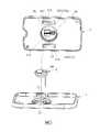
參閱圖1與圖2,本發明生理訊號傳感裝置之一第一實施例,適用於透過一植針組件9(見圖8)來安裝至一生物體(圖未示)的皮表,並用於量測該生物體中的至少一種分析物質,以及傳送一對應該分析物質的生理訊號,其中該分析物質可為生物體體液中的葡萄糖值,但不以此為限。另外,如圖2所示,定義一第一軸向D1、一垂直該第一軸向D1的第二軸向D2,及一垂直該第一軸向D1及該第二軸向D2的第三軸向D3,但在其他實施態樣中,該第一軸向D1、該第二軸向D2及該第三軸向D3任兩者之間的夾角並非限於90度。Referring to Figures 1 and 2, a first embodiment of the physiological signal sensing device of the present invention is suitable for mounting to the skin surface of a living object (not shown) through a needle implant assembly 9 (see Figure 8), and used for Measure at least one analyte in the organism, and transmit a physiological signal corresponding to the analyte, wherein the analyte can be the glucose value in the biological fluid, but it is not limited to this. In addition, as shown in FIG. 2, a first axis D1, a second axis D2 perpendicular to the first axis D1, and a third axis D1 perpendicular to the second axis D2 are defined. The axial direction is D3, but in other embodiments, the angle between any two of the first axial direction D1, the second axial direction D2, and the third axial direction D3 is not limited to 90 degrees.
在本實施例中,該生理訊號傳感裝置是用來量測人體組織間液(Interstitial Fluid,ISF)中的葡萄糖濃度,該生理訊號傳感裝置包含一底座1、一感測器2,及一傳感器3。In this embodiment, the physiological signal sensing device is used to measure the glucose concentration in the interstitial fluid (ISF) of the human body. The physiological signal sensing device includes a
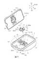
該底座1包括一底座本體11,及設置於該底座本體11的至少一第一卡合結構12。The
參閱圖2及圖5,該底座本體11具有一垂直該第一軸向D1的底板111、一由該底板111的周緣沿該第一軸向D1延伸的圍壁112、一凸設於該底板111的一頂面115且與該底板111共同界定出一設置槽113的槽周壁114,及至少一貫穿該底板111的開口117。該底板111具有該頂面115、一沿該第一軸向D1相反於該頂面115的底面116,及一貫穿該頂面115及該底面116且連通該設置槽113的穿孔118(見圖3)。於本實施例中,該開口117之數量為兩個,且沿該第三軸向D3間隔該設置槽113。2 and 5, the
於本實施例中,該底座1具有兩個第一卡合結構12,該等第一卡合結構12凸設於該底板111的該頂面115,且沿該第三軸向D3間隔該設置槽113,並分別相鄰該等開口117。In this embodiment, the
參閱圖2及圖4,該底座本體11可透過一貼片16而貼覆至生物體皮表。該貼布16設置於該底座本體11的底面116,並包括一對應該底座本體11的該穿孔118的植孔161,及一圍繞該植孔161且不吸水的防水部162。於本實施例中,該貼布16由不織布材質製成且相反兩面分別設有黏膠,其中一面貼設於該底座本體11的該底面116,另一面則用來貼設於該生物體皮表。然而,該底座1也可以省略該貼布16,而由使用者自行在該底座本體11的底面116貼膠,以使該底座1黏附於該生物體的皮表。詳細說明的是,該貼布16的防水部162為不織布經由點膠後滲入不織布而形成,其旨在於在將生理訊號傳感裝置設置於生物體皮表後防止汙水經由貼布16滲透而接觸至傷口,進而造成傷口感染的風險。2 and 4, the
該感測器2包括一設置於該底座本體11的固定座21,及一設置於該固定座21並受該固定座21限位的感測試片22,且該感測試片22適用於量測該生物體中的該分析物質,並傳送一對應該分析物質之數據的生理訊號至該傳感器3。The
參閱圖2、圖4至圖7,該固定座21設置於該底座本體11的設置槽113。該固定座21具有一底面211、一頂面212、一連接該底面211及該頂面212之間的外周面213、一位於底面211與頂面212之間且向上開放的設置空間210,及一沿一植入方向D4貫穿該底面211及該頂面212的貫孔214。該貫孔214與該設置空間210為間隔設置並於一延伸方向D5上與該設置空間210相互連通。該植入方向D4與該延伸方向D5夾一角度
該感測試片22具有一用來植入生物體皮下的感測段222、一電連接該傳感器3的訊號輸出段221,及一沿該延伸方向連接該感測段222及該訊號輸出段221的延伸段223,該感測段222穿設於該貫孔214的一底部214b,該訊號輸出段221容置於該設置空間210,該延伸段223由該設置空間210延伸至該貫孔214。該感測段222用來量測與該分析物質相關之生理參數,並將前述量測結果依序經由延伸段223與訊號輸出段221傳送至傳感器3。如圖6所示,該感測試片22藉由其表面的複數電極延伸至訊號輸出段221的訊號輸出端226電連接該傳感器3以傳遞生理訊號,而該等電極的型態及其數量均視所需量測之分析物而定,而不以本實施例圖中所示為限。為避免圖式不清,感測試片22位於訊號輸出段221上之訊號輸出端及相關電連接端子的配置僅示意於圖6,而不繪製於其他圖示。The
此外,該設置空間210具有一開放於該頂面212的空腔部210a,及一沿該第一軸向D1連通該空腔部210a的夾縫部210b。參閱圖4、圖6及圖7,該感測試片22的該訊號輸出段221位於該空腔部210a並且沿該第一軸向D1凸出該固定座21的頂面212。而該延伸段223沿該延伸方向D5延伸於該夾縫部210b,該感測段223則沿該植入方向D4向下穿設於該貫孔214並經由於該底座本體11的該穿孔118穿出該底座本體11的底面116,以植入生物體皮表下。In addition, the setting
該固定座21的該貫孔214及該底座本體11的該穿孔118共同構成一沿該植入方向D4沿伸的植針路徑c。該植針路徑c用來供一植入裝置(圖未示)的一植針組件9穿設(見圖8),以將該感測試片22的該感測段222植入該生物體的皮下組織。The through
參閱圖2、圖4及圖5,該傳感器3可分離地蓋設於該底座1且連接該感測器2,該傳感器3用來接收及輸出該感測器2所傳送的生理訊號。Referring to FIGS. 2, 4 and 5, the
該傳感器3包括一界定出一內部空間30的外殼300、一位於該內部空間30的電路板33、一位於該內部空間30且電連接該電路板33的電池35、一連接該電路板33底面且朝該底座本體11的方向凸出該內部空間30的連接埠36,及至少一設置於該底部31且可分離地與該底座本體11的第一卡合結構12卡合的第二卡合結構37。The
參閱圖3及圖5,該外殼300包括一底部31,及一頂部32,於本實施例中,該底部31及該頂部32分別為兩個相接合的殼體。該底部31相鄰該底座本體11且面對該底板111的該頂面115,並包括一底面311、一頂面312、一凹設於該底面311的第一凹槽313,及至少一凹設於該底面311且分別對應該底座1的第一卡合結構12的第二凹槽314。該第一凹槽313由一連接該底面311的槽周面315及一連接該槽周面315的槽底面316所界定。於本實施例中,該第二凹槽314之數量為兩個。該傳感器3以該底部31面對該底座1而蓋設於該底座1,而該底面311貼近於該底座本體11的該底板111,且該第一凹槽313容置該底座本體11的該槽周壁114及該感測器2,以使該感測試片22耦接至該電路板33,該等第二凹槽314則容置該等第二卡合結構37及該等第一卡合結構12,如此可有效降低整體的厚度。Referring to FIGS. 3 and 5, the
該電路板33設有多個電子元件(圖未示)。該等電子元件與該電路板33共同構成一訊號傳輸模組(圖未示),該訊號傳輸模組用來接收及輸出該感測試片22量測到的生理訊號,而該等電子元件屬習知物件,如訊號放大器、類比數位訊號轉換器、處理器、傳輸器等,故在此不予贅述。The
參閱圖4,該電池35連接該電路板33。Referring to FIG. 4, the
參閱圖3及圖5,該連接埠36連接該電路板33的底面,且沿該第一軸向D1向下凸伸至該底部31的該第一凹槽313內,且該連接埠36包括一插孔367。該插孔367供該感測試片22的該訊號輸出段221插設,以允許該感測試片22電連接該電路板33。於本實施例中,該感測試片22是藉由複數位於該連接埠36內的導電件364與電路板33電連接,具體地,本實施例中該等導電件364為螺旋彈簧,且沿自身徑向分別抵接電路板33上的複數電性接點(圖未示),以及沿自身徑向抵接感測試片22上之複數電極的訊號輸出端226(見圖6)。3 and 5, the
參閱圖3及圖5,該等第二卡合結構37為孔槽型態,且數量為兩個,分別設置於該底部31的該等第二凹槽314內,且該等第二卡合結構37的位置及形狀對應該等第一卡合結構12。當該傳感器3以該底部31面對該底座本體11的該底板111的頂面115而蓋設於該底座1時,該底座1的該等第一卡合結構12卡合於該等第二卡合結構37。當欲拆換傳感器3時,該等第二卡合結構37及該等第一卡合結構12可受外力而相互分離,補充說明的是,於本實施例中,使用者可以使用手指或其他物品經由該等開口117,施力於該等第一卡合結構12及該等第二卡合結構37中至少一者或施力於該等第一卡合結構12及該等第二卡合結構37的相卡合處,來使其分離,但在其他態樣中,也可以省略該等開口117,而藉由該底座1之材質及結構設計,使該底座1可受到使用者施力而產生彎曲、形變,以使該等第二卡合結構37及該等第一卡合結構12分離。然而,在其他變化態樣,生理訊號傳感裝置中亦可同時存在具有可撓性的該底座本體11與用來進行拆卸的開口117,本發明並不欲以此為限。Referring to FIGS. 3 and 5, the second
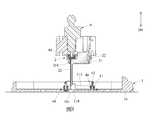
回到圖2,本實施例在使用前,該底座1、該感測器2及該傳感器3彼此分離而尚未組合在一起。而欲使用時,須將該底座1、該感測器2及該傳感器3結合,並設置於該生物體的皮表。參閱圖8,在設置的過程中,該底座1及該感測器2可先組合至一植入裝置(圖未示),接著使該植入裝置的該植針組件9承載該感測試片22的該感測段222並沿該植入方向D4穿過該固定座21的該貫孔214,接著透過該貼布16,將該底座本體11固定到該生物體的皮表,然後,透過該植入裝置將該感測試片22的該感測段222隨著該植針組件9穿過該底座本體11的該穿孔118,並植入該生物體的皮下組織,同時,該感測器2的該固定座21置入該底座本體11的該設置槽113。參閱圖9,隨後,將該植針組件9抽出,使該植入裝置與該感測器2及該底座1分離,此時,該感測器2結合於該底座1,且該感測試片22的感測段222植入該生物體的皮下組織。參閱圖4及圖5,最後,再將該傳感器3蓋合於該底座本體11,此時,該傳感器3的該等第二卡合結構37與該底座本體11的該等第一卡合結構12受外力推抵而相卡合,同時,該感測試片22的訊號輸出段221沿該第一軸向D1經由插孔367插設於該傳感器3的該連接埠36,如此,即完成整體裝設。Returning to FIG. 2, before this embodiment is used, the
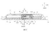
參閱圖4及圖5,經由前述說明可知,本生理訊號傳感裝置中該底座1、該感測器2與該傳感器3三者為可供使用者自行組合並拆卸之部件,再加上植入過程中,該植針組件9會貫穿該感測器2之固定座21的貫孔214,以及該底座1的該穿孔118,因此容易使外部液體,如生物體植入處所湧出的血液、體液,經由一第一液體滲漏路徑a及該植針路徑c進入該傳感器3內部或經由路徑d接觸感測試片22的訊號輸出段221,以及外部汙水經由一第二液體滲漏路徑b進入該傳感器3內部,甚至有可能再循著該第一液體滲漏路徑a回流至生物體植入處(即傷口處)。詳細說明的是,該第一液體滲漏路徑a為由該穿孔118進入並經由該底座1及該感測器2之該固定座21之間,朝向該感測試片22與該傳感器3耦接之處延伸;該第二液體滲漏路徑b為由該底座1及該傳感器3之間的間隙進入,並由該底座1及該傳感器3的外緣朝向該感測試片22與該傳感器3耦接之處延伸;該植針路徑c由該穿孔118及該貫孔214延伸至該感測試片22與該傳感器3耦接之處。因此,本發明生理訊號傳感裝置之第一實施例還包含一密封單元4,用於防止外部液體經由上述路徑滲入,而影響該感測試片22的量測功能、損毀該傳感器3內部電子元件,甚至是造成傷口處的感染。Referring to Figures 4 and 5, it can be seen from the foregoing description that the
參閱圖4及圖5,該密封單元4包括一第一密封件42、一第二密封件41、一第三密封件48、一第六密封件49、一頂抵件組47,及一阻隔件45。4 and 5, the sealing
概略來說,該密封單元4主要藉由該第一密封件42夾設於該感測器2之該固定座21及該傳感器3之該底部31之間,以密封該第一液體滲漏路徑a;該第二密封件41夾設於該底座1與該傳感器3之間,以密封該第二液體滲漏路徑b;該第三密封件48夾設於該底座1之該槽周壁114的內壁面及該感測器2之該固定座21的一外周面213之間,以密封該第一液體滲漏路徑a;該頂抵件組47位於該傳感器3的該底部31與該感測器2之該固定座21的該貫孔214之間,該頂抵件組47密封該感測器2之固定座21的該貫孔214,以密封該植針路徑c。而該密封單元4在各個實施例中的具體的設置方式,接下來將依序說明。Roughly speaking, the sealing
該第一密封件42夾設於該感測器2之該固定座21的一外周面及該傳感器3之該第一凹槽313的一槽周面315之間,以密封該第一液體滲漏路徑a。於本實施例中,該第一密封件42除了接觸該感測器2之該固定座21與該傳感器3之該第一凹槽313外可進一步抵接於該設置槽之該槽周壁114的上緣,以同時密封該第一液體滲漏路徑a以及該第二液體滲漏路徑b。因此,本實施例的第一密封件42可防止外部液體(尤其是血液),由該底座本體11的該穿孔118,經由該底座本體11及該固定座21之間,流向該傳感器3的該槽底面316及該固定座21的頂面212之間,也可防止血液由該底座本體11的該穿孔118,依序循著該第一液體滲漏路徑a與第二液體滲漏路徑b,滲出生理訊號傳感裝置外,引發使用者的恐慌。於此同時,本實施例的第一密封件42更可進一步防止外部的液體(尤其是汙水),由該底座1的圍壁112及該傳感器3的頂部32之間,流入該傳感器3的該槽底面316及該固定座21的頂面212之間,再由該連接埠36的該插孔367進入該傳感器3的內部,也可以防止汙水經由該第二液體滲漏路徑b進入裝置內部後再經由該第一液體滲漏路徑a流至穿孔118而接觸到傷口。The
該第二密封件41夾設於該底座1與該傳感器3之間,以密封該第二液體滲漏路徑b。本實施例中,該第二密封件41夾設於該底座的該槽周壁114的一外壁面及該傳感器3的該第一凹槽313的槽周面315之間。更具體來說,該第二密封件41可防止外部的液體(尤其是汙水),由該底座1的圍壁112及該傳感器3的頂部32之間,流入該傳感器3的該槽底面316及該固定座21的頂面212之間,再由該連接埠36的該插孔367進入該傳感器3的內部。於此同時,也可防止外部液體(尤其是血液),由該底座本體11的該穿孔118,經由該底座本體11及該固定座21之間(即第一液體滲漏路徑a),流向傳感器3的底部31與底座本體11的頂面115之間(即第二液體滲漏路徑b),進而滲出生理訊號傳感裝置外,引發使用者的恐慌。The
該第三密封件48夾設於該底座1之該槽周壁114的一內壁面及該感測器2之該固定座21的一外周面213之間,以與該第一密封件42共同密封該第一液體滲漏路徑a,主要可防止外部液體(尤其是血液),由該底座本體11的該穿孔118,經由該底座本體11及該固定座21之間,流向該傳感器3的該槽底面316及該固定座21的頂面212之間。此外,該第三密封件48具彈性,且該感測器2之固定座21的該外周面213緊抵於該第三密封件48,可進一步使該固定座21固定於該設置槽113。需注意的是,在本實施例中,因於設置槽113內設置第三密封件48來固定感測器2的固定座21,相較於市面上既有產品常見以在底座本體11上破孔並搭配密封件來固定感測器2的方式來說,本實施例所提供之生理訊號傳感裝置的密封性佳。The
第六密封件49圍繞該槽周壁114的外側且夾設於該底座1的該底板111的頂面115及該傳感器3的一底面311之間,以與該第二密封件41共同密封該第二液體滲漏路徑b。必須說明的是,第六密封件49的設置等同於是對第二液體滲漏路徑b的第一道防線,可先行將汙水防堵於外,更有效地防止汙水靠近整體裝置的核心位置(即設置槽113、固定座21內的感測試片與傳感器3的插孔367),同時能提升第二密封件41與第一密封件42的耐用性。The
據此,整體來看在本實施例中針對防汙水的部分,第六密封件49可作為第一道防線,第二密封件41則可作為第二道防線,第一密封件42除了是防汙水進入裝置內部的第三道防線,更可防止汙水再循著第一液體滲漏路徑a通過穿孔118接觸到傷口引發感染。至於防血功能,為避免血液經由穿孔118進入後沿著固定座21與設置槽113間的間隙(即第一液體滲漏路徑a)流往傳感器3,第三密封件可作為第一道防線,而第一密封件42是第二道防線,且更可防止血液循著第二液體滲漏路徑b流出裝置外部,造成使用者的恐慌。Based on this, as a whole, for the anti-sewage part in this embodiment, the
參閱圖9,於本實施例中,該第一密封件42、該第二密封件41、該第三密封件48及第六密封件49由彈性材質,如橡膠,以一體成形之方式製成並設置於該底座1,但也可以為其他可防止液體滲漏的彈性材質,而不以此為限。。詳細來說,在本實施例中為了能為了製造時可一次射出成形,而將該第一密封件42、該第二密封件41、該第三密封件48及第六密封件49一體成形於底座1上,可利用彈性材料射出環繞底座本體11之槽周壁114的外壁面而形成該第二密封件41並至少部分向下延伸而嵌入該底板111,並與底板111共平面或稍微突出於底板111的底面116形成一連接部411,再向上延伸並環繞槽周壁114的內壁面而形成該第三密封件48。同理,第二密封件41也可部分沿著底板111的頂面115朝向設置槽113外延伸出另一連接部412後環繞設置槽113一圈而形成第六密封件49。第三密封件48亦可部分沿著槽周壁114的內壁面向上延伸又一連接部413後包覆槽周壁114的上緣以形成第一密封件42。然而,必須說明的是,該第一密封件42、該第二密封件41、該第三密封件48及第六密封件49也可以彼此獨立設置於該底座1而不相連接。Referring to FIG. 9, in this embodiment, the first sealing
此外,如圖9所示,由第二密封件41部分向下延伸並嵌入底板111的連接部411可與貼布16或是直接貼附的生物體皮表間相互擠壓干涉而發揮如同前述貼布16中的防水部162的作用,防止汙水滲入接觸傷口而造成傷口感染。必須說明的是,設置防水部162或設置該連接部411可擇一為之,本發明不以此為限。In addition, as shown in FIG. 9, the connecting
參閱圖4與圖7,該頂抵件組47密封該貫孔214的頂部214a,概略來說,該頂抵件組47具有一位於該傳感器3之該底部31的頂抵件46,該頂抵件46的位置對應該固定座21的該貫孔214並與該貫孔214的頂部214a緊密結合。具體來說,該頂抵件組47具有一位於該傳感器3的該第一凹槽313的一槽底面316的頂抵件46,及一設置於該貫孔214頂部214a的第四密封件44,該頂抵件46與該第四密封件44緊密結合,以密封該植針路徑c,避免血液經由該連接埠36的該插孔367進入該傳感器3的內部,損毀傳感器3內部的電子元件。該第四密封件44為一軟件且由彈性材質製成,如橡膠,而該頂抵件46則是由相對於該第四密封件44較堅硬之材質製成的一硬件,且與該傳感器3的底部31為一體成形製成。該第四密封件44及該頂抵件46兩者外型配合以彼此緊密塞抵,以加強密封該植針路徑c的效果。此外,由於該第四密封件44為一軟件且由彈性材質製成(如橡膠),故可在該植針組件9(參閱圖8)抽出後密合以進一步維持裝置內部的密封性。另外,本實施例中,該第四密封件44向上凸出該固定座22的頂面212,而該固定座22的頂面212則另外凸設有二彈性件50,以使該固定座22平穩接觸該傳感器3。4 and 7, the abutting member set 47 seals the top 214a of the through
藉此,本實施例藉由在該底座1上設置該第一密封件42及/或該第三密封件48,並搭配在固定座21上該第四密封件44的設置,可在使用者利用植入組件引導該底座1貼覆至生物體皮表上,使該感測器2的該感測試片22部分植入生物體皮表下,且尚未安裝該傳感器3時,將瞬間湧出的血液全都密封在該底座1與該感測器2的縫隙內或該感測器2的該固定座21內,避免使用者因見到血液而恐慌,此外,亦可縮短安裝該傳感器3至該底座1上所需等待的時間。Therefore, in this embodiment, by arranging the
再者,如圖4與圖7所示,該阻隔件45設置於該貫孔214及該設置空間210之間並阻隔該貫孔214及該設置空間210,該阻隔件45由彈性材質製成並緊抵該感測試片22的延伸段223,以防止血液經由貫孔214循著路徑d滲入該設置空間210,進而接觸該感測試片22的訊號輸出段221,影響該感測試片22的感測功能。較佳地,該感測試片22的延伸段223的相對兩側可受該阻隔件45夾持以額外達到固定感測試片22之功效。此外,感測器2之固定座21底部可進一步經由灌膠23密封,等同於雙重防堵由路徑d或第一液體滲漏路徑a進入的外部液體(如血液)。Furthermore, as shown in FIGS. 4 and 7, the blocking
再補充說明,參閱圖3,本實施例中為了可有效縮小該生理訊號傳感裝置的厚度(也就是沿第一軸向D1之高度),將該傳感器3的該底部31的外型與該底座1及該感測器2相配合,而形成該第一凹槽313,如此可使該傳感器3的內部沿該第二軸向D2於該第一凹槽313的兩側形成有較大的內部空間,以容置該電池35以及設置於該電路板33的電子元件(圖未示),而該感測器2以及該連接埠36之間相配合的電連接構造便可完全集中在該第一凹槽313,使整體空間配置得到完全的利用並緻密化。In addition, referring to FIG. 3, in this embodiment, in order to effectively reduce the thickness of the physiological signal sensing device (that is, the height along the first axis D1), the appearance of the bottom 31 of the
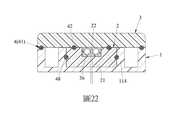
但在其他實施態樣中(請參閱圖21及圖22之示意),該傳感器3的該底部31也可以至少部分與該感測器2的該固定座21以及該底座1的外型呈互補配置,例如僅有連接埠36與該固定座21互補而省略該第一凹槽313(如圖22),而藉由該第一密封件42夾設於該感測器2之該固定座21及該傳感器3之該底部31之間,以密封該第一液體滲漏路徑a,該第二密封件41夾設於該底座1與該傳感器3之間,以密封該第二液體滲漏路徑b,該第三密封件48夾設於該底座1之該槽周壁114的內壁面及該感測器2之該固定座21的一外周面213之間,以密封該第一液體滲漏路徑a,同樣可達到防血及防水之功效。However, in other implementations (please refer to the schematic diagrams of FIGS. 21 and 22), the bottom 31 of the
由於藉由本生理訊號傳感裝置所量測者均為微小電流,甚至為至納安(培) (nA)的微小電流,故而在維持整體裝置內部的密封性外,更需進一步維持感測器2周遭的乾燥性,始能避免因其受潮而衍生量測誤差等問題,因此,本發明生理訊號傳感裝置之第一實施例還包含至少一乾燥劑5。As the physiological signal sensing device measures small currents, even as small as nanoamperes (nA), it is necessary to maintain the sensor in addition to maintaining the internal airtightness of the overall device. The dryness of the surrounding area can avoid problems such as measurement errors caused by moisture. Therefore, the first embodiment of the physiological signal sensor device of the present invention further includes at least one
參閱圖2及圖5,該乾燥劑5設置於,該傳感器3蓋設於該底座1後,該第一凹槽313與該底座1共同界定的一容置空間100中的任一處,以達到防潮目的並同時提升防水效果。於本實施例中,該容置空間100位於該底座1的該第一凹槽313及該傳感器3的該底部31之間,而該傳感器3與該感測試片22連接之處位於該容置空間100,而該等乾燥劑5設置在該固定座21的頂面212,且該固定座21的該頂面212具有二分別容置該等乾燥劑5的凹穴217。2 and 5, the
然而,在本實施例的另一變化態樣中,該等乾燥劑5亦可設置於傳感器3之該槽底面316,即可在該槽底面316增加兩個分別用來容置該等乾燥劑5的凹穴(圖未示)。而在其他實施態樣中,該等乾燥劑5也可以是製成該固定座21的材料之一,亦即在射出成型固定座21便選用具有乾燥效果的材料或將乾燥劑摻入射料中一同成型,使該固定座21本身具有乾燥功能。However, in another variation of this embodiment, the
參閱圖10至圖14,為本發明生理訊號傳感裝置之一第二實施例,在該密封單元4的配置上該第二實施例類似於該第一實施例,其主要差異在於:10 to 14 are a second embodiment of the physiological signal sensing device of the present invention. The second embodiment is similar to the first embodiment in the configuration of the
首先,參閱圖12,該密封單元省略該第三密封件48,並包括一第五密封件43。First, referring to FIG. 12, the sealing unit omits the third sealing
該第五密封件43設置於該底座1且密封該穿孔118,該第五密封件43具有一用來供該植針組件9(見圖8)穿設的預開孔431,以降低植針時的阻力,但第五密封件43亦可不設有預開孔,而由該植針組件9引導感測試片22通過時刺穿,且基於第五密封件43之材質可為彈性體(如橡膠),故可在該植針組件9抽出後密合並緊抵感測試片22之感測段222以維持裝置內部的密封性。另外,本實施例中,該第五密封件43密封該底座1的該穿孔118的頂部,以使該穿孔118的底部形成一容血空間,該容血空間可用來容置從植入處滲出的血液以做緩衝,進而避免流出的血液或體液因空間不足使液壓升高,而從該第五密封件43及該感測試片22之縫隙間滲入。The
另外,如圖10及圖12所示,在本實施例中第一密封件41與第五密封件43為了製造時可一次射出成形,而為一體成形製作於底座本體11上,但該第一密封件41及該第五密封件43也可以是獨立不相連的元件。而本實施例詳細來說是利用彈性材料射出環繞底座本體11之槽周壁114而形成該第一密封件41並至少部分向下延伸而嵌入該底板111,並與底板111共平面或稍微突出於底板111的底面116形成一連接部411,再向上延伸並環繞穿孔118而形成該第五密封件43。藉此,該連接部411可與貼布16或是直接貼附的生物體皮表間可相互擠壓干涉而發揮如同前述貼布16中的防水部162的作用,防止汙水滲入接觸傷口而造成傷口感染。必須說明的是,設置防水部162或設置該連接部411可擇一為之,本發明不以此為限。另外,在其他實施態樣中,該連接部411也可以由第五密封件43沿該穿孔118的孔面環繞延伸至該穿孔118的底端,以及該貼布16的該植孔161的孔面,並用來在使用時靠抵該生物體皮表,並圍繞植入處,以阻隔來自於該貼布16的液體,以避免傷口感染,而藉此,於該實施態樣中,也可以省略貼布16中的防水部162。In addition, as shown in FIGS. 10 and 12, in this embodiment, the first sealing
其次,參閱圖11、圖13及圖14,該第一密封件42同樣夾設在於該感測器2之該固定座21的外周面213及該傳感器3之該第一凹槽313的槽周面315之間,但第二實施例中該第一密封件42設置於該感測器2之固定座21的外周面213,且並未抵接該槽周壁114之上緣。據此,在第二實施例中針對防汙水的部分,以該第二密封件41作為第一道防線,該第一密封件42做為第二道防線,防止汙水由該底座1的圍壁112及該傳感器3的頂部32之間(即第二液體滲漏路徑b),流入該傳感器3的該槽底面316及該固定座21的頂面212之間,再由該連接埠36的該插孔367進入該傳感器3的內部。至於防血功能,為避免血液經由穿孔118進入後沿著固定座21與設置槽113間的間隙(即第一液體滲漏路徑a)流往傳感器3,以該第五密封件43作為第一道防線,依然能在植入生物體時立即地防堵血液的滲漏,並以該第一密封件42作為第二道防線。此外,該第二密封件41也可進一步作為防止血液循著第二液體滲漏路徑b流出裝置外部的防線,進而避免造成使用者的恐慌,而該第五密封件43也可防止汙水再循著第一液體滲漏路徑a通過穿孔118接觸到傷口引發感染。Next, referring to Figures 11, 13 and 14, the first sealing
另外,參閱圖12,於本實施例中,該頂抵件組47的該頂抵件46為一軟件(如橡膠)並凸設於該傳感器3的底部31的槽底面316,該第四密封件44為一軟件(如橡膠)並設置於該貫孔214的頂部214a,且該貫孔214的頂部214a呈凹槽狀供該第四密封件44容置,而該第四密封件44的頂部亦呈凹槽狀,並供頂抵件46塞抵,以加強密封該植針路徑c的效果。In addition, referring to FIG. 12, in this embodiment, the abutting
補充說明的是,該第二密封件41及該第五密封件43之間,及該第一密封件42及該第四密封件44之間,可根據製造方式而一體成形地連接並分別設置於該底座1及該感測器2之固定座21,但也可以彼此獨立,如圖15為本實施例之一變化態樣,於該變化態樣中,該密封單元4的該第二密封件41與該第五密封件43彼此獨立且不相連接,此外,該第二密封件41及該第一密封件42為O型環,其中又以截面形狀為三角形的O型環防液體滲漏效果較佳,但不以此為限。It is supplemented that the second sealing
此外,本實施例中,該底座1的設置槽113內設有一卡固件14,用來與該固定座21的底部相卡合。In addition, in this embodiment, a
參閱圖16,為本發明生理訊號傳感裝置之一第三實施例,該第三實施例類似於該第二實施例,其差異在於:Refer to FIG. 16, which is a third embodiment of the physiological signal sensing device of the present invention. The third embodiment is similar to the second embodiment, and the difference lies in:
該密封單元4的該頂抵件組47省略該第四密封件44,該頂抵件46直接堵塞於該固定座21的該貫孔214的頂部214a,且在此實施例中該頂抵件46為一軟件(如橡膠)而可藉由擠壓變形而與該貫孔214的頂部214a相互干涉以達到密封該植針路徑c的效果。The abutting
參閱圖17,為本發明生理訊號傳感裝置之一第四實施例,在第四實施例中該第一密封件42、該第二密封件41、第五密封件43等配置類似於該第二實施例,但該頂抵件組47的配置則與第一實施例相同。也就是說,在第四實施例中,該第四密封件44為一軟件且由彈性材質製成,如橡膠,而該頂抵件46則是由相對於該第四密封件44較堅硬之材質製成的一硬件,且與該傳感器3的底部31為一體成形製成,並與該第四密封件44頂部之形狀相配合,而抵塞於該第四密封件44頂部以達到密封該植針路徑c的效果。Refer to FIG. 17, which is a fourth embodiment of the physiological signal sensing device of the present invention. In the fourth embodiment, the configuration of the first sealing
參閱圖18,為本發明生理訊號傳感裝置之一第五實施例,該第五實施例類似於該第二實施例,其差異在於:Refer to FIG. 18, which is a fifth embodiment of the physiological signal sensing device of the present invention. The fifth embodiment is similar to the second embodiment, and the difference lies in:
該傳感器3的底部31對應該貫孔214的頂部214a的位置上具有另一凹槽,並於該凹槽中設置彈性材質的頂抵件46,且該頂抵件46與該凹槽的形狀相對應,故在第五實施例中該密封單元4的該頂抵件46為向上凹陷的凹槽狀結構,該第四密封件44則向上凸起,並與該頂抵件46相互頂抵,彼此可藉由相互擠壓達到密封該植針路徑c的效果。The bottom 31 of the
參閱圖19,為本發明生理訊號傳感裝置之一第六實施例,該第六實施例類似於該第五實施例,其差異在於:Refer to FIG. 19, which is a sixth embodiment of a physiological signal sensing device of the present invention. The sixth embodiment is similar to the fifth embodiment, and the difference lies in:
該傳感器3的底部31對應該貫孔214的頂部214a的位置上同樣形成有向上凹陷的凹槽狀結構,但在第六實施例中以該凹槽狀結構作為頂抵件46,且因該頂抵件46與該傳感器3的底部31為一體成形而為硬件,該第四密封件44為由貫孔214的頂部214a向上凸起的軟件,藉由該第四密封件擠壓於該頂抵件46的底面而變形,達到密封該植針路徑c的效果。At the bottom 31 of the
參閱圖20,為本發明生理訊號傳感裝置之一第七實施例,該第七實施例類似於該第二實施例,其差異在於:Referring to FIG. 20, it is a seventh embodiment of the physiological signal sensing device of the present invention. The seventh embodiment is similar to the second embodiment, and the difference lies in:
在第七實施例中將該第一密封件42與該第二密封件41整合為單一密封件,夾設於該感測器2之該固定座21的外周面213、該傳感器3之該第一凹槽313的槽周面315以及該底座1之間,以同時密封該第一液體滲漏路徑a與該第二液體滲漏路徑b。具體來說,該固定座21及該傳感器3的槽周面315間僅設置第一密封件42,且該第一密封件42同時抵接於該底座1的該槽周壁114頂緣,以同時達到防血自該第一液體滲漏路徑a以及防汙水自該第二液體滲漏路徑b進入該傳感器3內部的效果。In the seventh embodiment, the first sealing
綜上所述,本發明生理訊號傳感裝置,利用該密封單元4來密封不同的滲漏路徑,以有效防止外部汙水、血液、體液等外部液體進入該傳感裝置,並可防止在植入生物體皮下時,血液或體液瞬間湧出並為使用者所得以觀見,從而降低使用者的恐懼感,故確實能達成本發明之目的。In summary, the physiological signal sensor device of the present invention uses the
惟以上所述者,僅為本發明之實施例而已,當不能以此限定本發明實施之範圍,凡是依本發明申請專利範圍及專利說明書內容所作之簡單的等效變化與修飾,皆仍屬本發明專利涵蓋之範圍內。However, the above are only examples of the present invention. When the scope of implementation of the present invention cannot be limited by this, all simple equivalent changes and modifications made in accordance with the scope of the patent application of the present invention and the content of the patent specification still belong to This invention patent covers the scope.
1:底座11:底座本體111:底板112:圍壁113:設置槽114:槽周壁115:頂面116:底面117:開口118:穿孔12:第一卡合結構14:卡固件16:貼布161:植孔162:防水部2:感測器21:固定座210:設置空間210a:空腔部210b:夾縫部211:底面212:頂面213:外周面214:貫孔214a:頂部214b:底部217:凹穴22:感測試片221:訊號輸出段222:感測段223:延伸段226:訊號輸出端23:膠3:傳感器30:內部空間300:外殼31:底部311:底面312:頂面313:第一凹槽314:第二凹槽315:槽周面316:槽底面32:頂部33:電路板35:電池36:連接埠364:導電件367:插孔37:第二卡合結構4:密封單元41:第二密封件411:連接部412:連接部413:連接部42:第一密封件43:第五密封件431:預開孔44:第四密封件45:阻隔件46:頂抵件47:頂抵件組48:第三密封件49:第六密封件50:彈性件5:乾燥劑9:植針組件100:容置空間D1:第一軸向D2:第二軸向D3:第三軸向D4:植入方向D5:延伸方向
本發明之其他的特徵及功效,將於參照圖式的實施方式中清楚地呈現,其中:圖1是本發明生理訊號傳感裝置的一第一實施例的一立體圖;圖2是該第一實施例的一立體分解圖;圖3是該第一實施例的另一立體分解圖;圖4是沿圖1中之線Ⅳ-Ⅳ所取得的一剖視圖;圖5是沿圖1中之線Ⅴ-Ⅴ所取得的一剖視圖;圖6是該第一實施例的一感測器的一立體圖;圖7是該第一實施例的該感測器的一剖視圖;圖8是該第一實施例的該底座及該感測器的一剖視圖,說明該感測器結合至一植針組件且尚未結合至該底座時的狀態;圖9是該第一實施例的該底座及該感測器的一剖視圖,說明該感測器結合至該底座,且抽出該植針組件後的狀態;圖10是本發明生理訊號傳感裝置的一第二實施例的一立體圖;圖11是該第二實施例的一感測器的一剖視圖;圖12是該第二實施例的一剖視圖;圖13是該第二實施例的另一剖視圖;圖14是該第二實施例的該底座及該感測器的一剖視圖,說明該感測器結合至該底座,且抽出該植針組件後的狀態;圖15是該第二實施例的一變化態樣的一剖視圖;圖16是本發明生理訊號傳感裝置的一第三實施例的一剖視圖;圖17是本發明生理訊號傳感裝置的一第四實施例的一剖視圖;圖18是本發明生理訊號傳感裝置的一第五實施例的一剖視圖;圖19是本發明生理訊號傳感裝置的一第六實施例的一剖視圖;圖20是本發明生理訊號傳感裝置的一第七實施例的一剖視圖;圖21是本發明生理訊號傳感裝置的一變化態樣的一剖面示意圖;及圖22是本發明生理訊號傳感裝置的另一變化態樣的一剖面示意圖。Other features and effects of the present invention will be clearly presented in the embodiments with reference to the drawings, in which:1 is a perspective view of a first embodiment of the physiological signal sensing device of the present invention;Figure 2 is a perspective exploded view of the first embodiment;Figure 3 is another perspective exploded view of the first embodiment;Figure 4 is a cross-sectional view taken along the line IV-IV in Figure 1;Figure 5 is a cross-sectional view taken along the line Ⅴ-Ⅴ in Figure 1;Fig. 6 is a perspective view of a sensor of the first embodiment;Figure 7 is a cross-sectional view of the sensor of the first embodiment;FIG. 8 is a cross-sectional view of the base and the sensor of the first embodiment, illustrating the state when the sensor is coupled to a needle implant assembly and not yet coupled to the base;9 is a cross-sectional view of the base and the sensor of the first embodiment, illustrating the state after the sensor is coupled to the base and the needle implant assembly is withdrawn;10 is a perspective view of a second embodiment of the physiological signal sensing device of the present invention;Figure 11 is a cross-sectional view of a sensor of the second embodiment;Figure 12 is a cross-sectional view of the second embodiment;Figure 13 is another cross-sectional view of the second embodiment;14 is a cross-sectional view of the base and the sensor of the second embodiment, illustrating the state after the sensor is coupled to the base and the needle implant assembly is withdrawn;15 is a cross-sectional view of a modified aspect of the second embodiment;16 is a cross-sectional view of a third embodiment of the physiological signal sensing device of the present invention;17 is a cross-sectional view of a fourth embodiment of the physiological signal sensing device of the present invention;18 is a cross-sectional view of a fifth embodiment of the physiological signal sensing device of the present invention;19 is a cross-sectional view of a sixth embodiment of the physiological signal sensing device of the present invention;20 is a cross-sectional view of a seventh embodiment of the physiological signal sensing device of the present invention;21 is a schematic cross-sectional view of a change aspect of the physiological signal sensing device of the present invention; and22 is a schematic cross-sectional view of another variation of the physiological signal sensing device of the present invention.
1:底座1: base
11:底座本體11: base body
111:底板111: bottom plate
112:圍壁112: Wall
113:設置槽113: set slot
114:槽周壁114: groove wall
115:頂面115: top surface
117:開口117: open
118:穿孔118: Piercing
12:第一卡合結構12: The first engagement structure
16:貼布16: patch
2:感測器2: sensor
21:固定座21: fixed seat
212:頂面212: top surface
217:凹穴217: dent
22:感測試片22: sensory test piece
3:傳感器3: sensor
300:外殼300: shell
31:底部31: bottom
313:第一凹槽313: first groove
314:第二凹槽314: second groove
32:頂部32: top
36:連接埠36: Port
4:密封單元4: Sealing unit
41:第二密封件41: second seal
42:第一密封件42: The first seal
44:第四密封件44: The fourth seal
49:第六密封件49: sixth seal
5:乾燥劑5: Desiccant
D1:第一軸向D1: first axis
D2:第二軸向D2: second axis
D3:第三軸向D3: third axis
D4:植入方向D4: Implantation direction
D5:延伸方向D5: Extension direction
Claims (40)
Translated fromChinesePriority Applications (25)
| Application Number | Priority Date | Filing Date | Title |
|---|---|---|---|
| CN202010315073.5ACN112294307B (en) | 2019-08-02 | 2020-04-21 | Physiological signal sensing device |
| CN202010314803.XACN112294306B (en) | 2019-08-02 | 2020-04-21 | Physiological signal sensing device |
| CN202010314695.6ACN112294305B (en) | 2019-08-02 | 2020-04-21 | Physiological signal sensing device |
| US16/944,582US11737689B2 (en) | 2019-08-02 | 2020-07-31 | Physiological signal monitoring device |
| US16/944,783US20210030360A1 (en) | 2019-08-02 | 2020-07-31 | Physiological signal monitoring device |
| US16/944,830US11717198B2 (en) | 2019-08-02 | 2020-07-31 | Physiological signal monitoring device |
| US16/944,734US11707213B2 (en) | 2019-08-02 | 2020-07-31 | Physiological signal monitoring device |
| CA3088621ACA3088621C (en) | 2019-08-02 | 2020-07-31 | Physiological signal monitoring device |
| PCT/IB2020/057252WO2021024128A1 (en) | 2019-08-02 | 2020-07-31 | Physiological signal monitoring device |
| EP20188961.5AEP3771407B1 (en) | 2019-08-02 | 2020-07-31 | Physiological signal monitoring device |
| CA3088595ACA3088595C (en) | 2019-08-02 | 2020-07-31 | Physiological signal monitoring device |
| EP20189188.4AEP3771399A1 (en) | 2019-08-02 | 2020-08-03 | Physiological signal monitoring device |
| EP20189221.3AEP3771428B1 (en) | 2019-08-02 | 2020-08-03 | Physiological signal monitoring device |
| JP2020131797AJP6963660B2 (en) | 2019-08-02 | 2020-08-03 | Physiological signal monitoring device |
| KR1020200096911AKR102442999B1 (en) | 2019-08-02 | 2020-08-03 | biosignal monitoring device |
| JP2020131794AJP6935555B2 (en) | 2019-08-02 | 2020-08-03 | Physiological signal monitoring device |
| KR1020200096693AKR102443002B1 (en) | 2019-08-02 | 2020-08-03 | biosignal monitoring device |
| AU2020213271AAU2020213271B2 (en) | 2019-08-02 | 2020-08-03 | Physiological signal monitoring device |
| AU2020213273AAU2020213273B2 (en) | 2019-08-02 | 2020-08-03 | Physiological signal monitoring device |
| KR1020200096692AKR102443001B1 (en) | 2019-08-02 | 2020-08-03 | biosignal monitoring device |
| EP20189139.7AEP3771417B1 (en) | 2019-08-02 | 2020-08-03 | Physiological signal monitoring device |
| JP2020131796AJP7014865B2 (en) | 2019-08-02 | 2020-08-03 | Physiological signal monitoring device |
| US17/809,411US20220323010A1 (en) | 2019-08-02 | 2022-06-28 | Physiological signal monitoring device and mounting method therefor |
| US18/337,808US20230329603A1 (en) | 2019-08-02 | 2023-06-20 | Physiological signal monitoring device |
| US18/352,887US20240016420A1 (en) | 2019-08-02 | 2023-07-14 | Physiological signal monitoring device |
Applications Claiming Priority (2)
| Application Number | Priority Date | Filing Date | Title |
|---|---|---|---|
| US201962882140P | 2019-08-02 | 2019-08-02 | |
| US62/882140 | 2019-08-02 |
Publications (2)
| Publication Number | Publication Date |
|---|---|
| TW202106236Atrue TW202106236A (en) | 2021-02-16 |
| TWI731545B TWI731545B (en) | 2021-06-21 |
Family
ID=71899622
Family Applications (26)
| Application Number | Title | Priority Date | Filing Date |
|---|---|---|---|
| TW109100967ATWI723733B (en) | 2019-08-02 | 2020-01-10 | Biosensor implantation device and implantation method |
| TW109100968ATWI735138B (en) | 2019-08-02 | 2020-01-10 | Physiological signal sensing device |
| TW109100992ATWI733304B (en) | 2019-08-02 | 2020-01-10 | A container for carrying sensor and its operating method. |
| TW109100957ATWI737122B (en) | 2019-08-02 | 2020-01-10 | Implantation device of biosensor |
| TW109100966ATWI729670B (en) | 2019-08-02 | 2020-01-10 | Implantation device of biosensor |
| TW109200433UTWM599631U (en) | 2019-08-02 | 2020-01-10 | Physiological signal sensing device |
| TW109100959ATWI735137B (en) | 2019-08-02 | 2020-01-10 | Physiological signal sensing device |
| TW109100961ATWI737123B (en) | 2019-08-02 | 2020-01-10 | Physiological signal sensing device |
| TW109100958ATWI723732B (en) | 2019-08-02 | 2020-01-10 | Biosensor implantation device and implantation method |
| TW109100852ATWI731545B (en) | 2019-08-02 | 2020-01-10 | Physiological signal sensing device |
| TW109100956ATWI723731B (en) | 2019-08-02 | 2020-01-10 | Biosensor implantation device and implantation method |
| TW109135338ATWI772920B (en) | 2019-08-02 | 2020-03-19 | Physiological Signal Sensing Device |
| TW109109245ATWI737224B (en) | 2019-08-02 | 2020-03-19 | Physiological signal sensing device |
| TW109109241ATWI737223B (en) | 2019-08-02 | 2020-03-19 | Physiological signal sensing device |
| TW109109242ATWI732494B (en) | 2019-08-02 | 2020-03-19 | Physiological signal sensing device |
| TW109110966ATWI737244B (en) | 2019-08-02 | 2020-03-31 | Physiological signal sensing device with electrostatic discharge protection mechanism |
| TW109124528ATWI754329B (en) | 2019-08-02 | 2020-07-21 | Physiological signal monitoring device and assembly method of sensor thereof |
| TW109125114ATWI760796B (en) | 2019-08-02 | 2020-07-24 | Needle implantation module and implantation device with needle implantation module |
| TW109126225ATWI764223B (en) | 2019-08-02 | 2020-08-03 | Physiological signal monitoring device and sensor holder thereof |
| TW109126221ATWI818185B (en) | 2019-08-02 | 2020-08-03 | Physiological signal monitoring device and sensor holder thereof |
| TW109126226ATWI756768B (en) | 2019-08-02 | 2020-08-03 | Physiological signal monitoring device and sensor holder thereof |
| TW109126242ATWI770572B (en) | 2019-08-02 | 2020-08-03 | Physiological signal monitoring system for fast assembly |
| TW110134989ATWI808493B (en) | 2019-08-02 | 2020-08-03 | Physiological signal monitoring device and sensor holder thereof |
| TW111129933ATW202245690A (en) | 2019-08-02 | 2020-08-03 | Method for assembling a physiological signal monitoring device |
| TW109126222ATWI745010B (en) | 2019-08-02 | 2020-08-03 | Physiological signal monitoring device and sensor holder thereof |
| TW109126237ATWI786421B (en) | 2019-08-02 | 2020-08-03 | Method for assembling a physiological signal monitoring device |
Family Applications Before (9)
| Application Number | Title | Priority Date | Filing Date |
|---|---|---|---|
| TW109100967ATWI723733B (en) | 2019-08-02 | 2020-01-10 | Biosensor implantation device and implantation method |
| TW109100968ATWI735138B (en) | 2019-08-02 | 2020-01-10 | Physiological signal sensing device |
| TW109100992ATWI733304B (en) | 2019-08-02 | 2020-01-10 | A container for carrying sensor and its operating method. |
| TW109100957ATWI737122B (en) | 2019-08-02 | 2020-01-10 | Implantation device of biosensor |
| TW109100966ATWI729670B (en) | 2019-08-02 | 2020-01-10 | Implantation device of biosensor |
| TW109200433UTWM599631U (en) | 2019-08-02 | 2020-01-10 | Physiological signal sensing device |
| TW109100959ATWI735137B (en) | 2019-08-02 | 2020-01-10 | Physiological signal sensing device |
| TW109100961ATWI737123B (en) | 2019-08-02 | 2020-01-10 | Physiological signal sensing device |
| TW109100958ATWI723732B (en) | 2019-08-02 | 2020-01-10 | Biosensor implantation device and implantation method |
Family Applications After (16)
| Application Number | Title | Priority Date | Filing Date |
|---|---|---|---|
| TW109100956ATWI723731B (en) | 2019-08-02 | 2020-01-10 | Biosensor implantation device and implantation method |
| TW109135338ATWI772920B (en) | 2019-08-02 | 2020-03-19 | Physiological Signal Sensing Device |
| TW109109245ATWI737224B (en) | 2019-08-02 | 2020-03-19 | Physiological signal sensing device |
| TW109109241ATWI737223B (en) | 2019-08-02 | 2020-03-19 | Physiological signal sensing device |
| TW109109242ATWI732494B (en) | 2019-08-02 | 2020-03-19 | Physiological signal sensing device |
| TW109110966ATWI737244B (en) | 2019-08-02 | 2020-03-31 | Physiological signal sensing device with electrostatic discharge protection mechanism |
| TW109124528ATWI754329B (en) | 2019-08-02 | 2020-07-21 | Physiological signal monitoring device and assembly method of sensor thereof |
| TW109125114ATWI760796B (en) | 2019-08-02 | 2020-07-24 | Needle implantation module and implantation device with needle implantation module |
| TW109126225ATWI764223B (en) | 2019-08-02 | 2020-08-03 | Physiological signal monitoring device and sensor holder thereof |
| TW109126221ATWI818185B (en) | 2019-08-02 | 2020-08-03 | Physiological signal monitoring device and sensor holder thereof |
| TW109126226ATWI756768B (en) | 2019-08-02 | 2020-08-03 | Physiological signal monitoring device and sensor holder thereof |
| TW109126242ATWI770572B (en) | 2019-08-02 | 2020-08-03 | Physiological signal monitoring system for fast assembly |
| TW110134989ATWI808493B (en) | 2019-08-02 | 2020-08-03 | Physiological signal monitoring device and sensor holder thereof |
| TW111129933ATW202245690A (en) | 2019-08-02 | 2020-08-03 | Method for assembling a physiological signal monitoring device |
| TW109126222ATWI745010B (en) | 2019-08-02 | 2020-08-03 | Physiological signal monitoring device and sensor holder thereof |
| TW109126237ATWI786421B (en) | 2019-08-02 | 2020-08-03 | Method for assembling a physiological signal monitoring device |
Country Status (10)
| Country | Link |
|---|---|
| US (7) | US11504032B2 (en) |
| EP (7) | EP3771409B1 (en) |
| JP (3) | JP6986603B2 (en) |
| KR (2) | KR102449247B1 (en) |
| CN (22) | CN112294301B (en) |
| AU (2) | AU2020294300B2 (en) |
| CA (2) | CA3104329A1 (en) |
| DE (1) | DE202020104460U1 (en) |
| TW (26) | TWI723733B (en) |
| WO (2) | WO2021023148A1 (en) |
Families Citing this family (37)
| Publication number | Priority date | Publication date | Assignee | Title |
|---|---|---|---|---|
| US9788771B2 (en) | 2006-10-23 | 2017-10-17 | Abbott Diabetes Care Inc. | Variable speed sensor insertion devices and methods of use |
| US11071478B2 (en) | 2017-01-23 | 2021-07-27 | Abbott Diabetes Care Inc. | Systems, devices and methods for analyte sensor insertion |
| CN112423664B (en) | 2018-06-07 | 2025-01-21 | 雅培糖尿病护理公司 | Focused sterilization and sterilized sub-assemblies for analyte monitoring systems |
| CA3230184A1 (en)* | 2019-08-02 | 2021-02-02 | Bionime Corporation | Physiological signal monitoring device |
| CN112294301B (en)* | 2019-08-02 | 2024-12-31 | 华广生技股份有限公司 | Physiological signal sensor device |
| EP4017357A4 (en)* | 2019-08-19 | 2023-04-19 | Medtrum Technologies Inc. | MEASURING DEVICE |
| CA3188510A1 (en) | 2020-08-31 | 2022-03-03 | Vivek S. RAO | Systems, devices, and methods for analyte sensor insertion |
| AU2021344214A1 (en)* | 2020-09-15 | 2023-03-23 | Abbott Diabetes Care Inc. | Systems, devices, and methods for analyte monitoring |
| US11852643B2 (en)* | 2020-10-13 | 2023-12-26 | Bionime Corporation | Physiological signal monitoring device |
| TWI793800B (en)* | 2020-10-14 | 2023-02-21 | 華廣生技股份有限公司 | Insertion needle structure and inserter |
| TWI849296B (en)* | 2021-01-08 | 2024-07-21 | 華廣生技股份有限公司 | Patch and method for using a patch |
| EP4346587A4 (en)* | 2021-05-31 | 2024-10-30 | Medtrum Technologies Inc. | ANALYTE DETECTION DEVICE INTEGRATED INTO A BATTERY ENCLOSURE |
| CN113499127B (en)* | 2021-06-28 | 2024-03-01 | 苏州百孝医疗科技有限公司 | Fixing structure of sensor base and method for removing sensor base |
| KR102592776B1 (en)* | 2021-06-29 | 2023-10-25 | 주식회사 아이센스 | Needle for transcutaneous sensor insertion and needle assembly having the same |
| CN115704820B (en)* | 2021-08-06 | 2025-08-05 | 上海移宇科技股份有限公司 | Body fluid analyte detection devices |
| CN115868974B (en)* | 2021-09-29 | 2025-09-09 | 上海微创生命科技有限公司 | Medical equipment and medical auxiliary device |
| CN116172549B (en)* | 2021-11-26 | 2025-08-12 | 上海微创生命科技有限公司 | medical devices |
| CN116195994A (en)* | 2021-11-30 | 2023-06-02 | 上海微创生命科技有限公司 | Sterilization box assembly, implanter and implantation system |
| CN114642426A (en)* | 2022-03-02 | 2022-06-21 | 苏州百孝医疗科技有限公司 | Method for manufacturing electronic device and electronic device |
| CN114831633B (en)* | 2022-04-29 | 2025-07-25 | 天津九安医疗电子股份有限公司 | Sensor implantation device |
| CN115089274A (en)* | 2022-05-26 | 2022-09-23 | 浙江康德莱医疗器械股份有限公司 | A puncture guide needle |
| WO2024028507A1 (en)* | 2022-08-05 | 2024-02-08 | Unomedical A/S | Inserter assembly and method |
| WO2024028506A1 (en)* | 2022-08-05 | 2024-02-08 | Unomedical A/S | Anchor assembly |
| TWD226583S (en)* | 2022-08-31 | 2023-07-21 | 華廣生技股份有限公司 | Physiological signal monitoring patch |
| TWD226584S (en)* | 2022-08-31 | 2023-07-21 | 華廣生技股份有限公司 | Physiological signal monitoring patch |
| TWD226582S (en)* | 2022-08-31 | 2023-07-21 | 華廣生技股份有限公司 | Physiological signal monitoring patch |
| TWI806771B (en)* | 2022-09-16 | 2023-06-21 | 英業達股份有限公司 | Anti-static electricity type electronic device |
| CN116058937A (en)* | 2022-10-11 | 2023-05-05 | 深圳可孚生物科技有限公司 | A biosensor-assisted implantation device |
| WO2024080457A1 (en)* | 2022-10-14 | 2024-04-18 | 국민대학교산학협력단 | Scalable implantable biosensor device |
| CN115399757B (en)* | 2022-10-31 | 2023-01-24 | 深圳刷新生物传感科技有限公司 | High-reliability implantation device of implantable biosensor |
| USD1095842S1 (en)* | 2023-02-10 | 2025-09-30 | I-Sens, Inc. | Continuous blood glucose measurement sensor |
| US20240298929A1 (en)* | 2023-03-08 | 2024-09-12 | Medtronic Minimed, Inc. | Substrate sealing configurations and methods |
| TWD231831S (en)* | 2023-03-15 | 2024-06-21 | 華廣生技股份有限公司 臺中市南區大慶街2段100號 (中華民國) | Part of a splitter for a physiological monitoring device |
| CN116626132A (en)* | 2023-05-15 | 2023-08-22 | 广州达安基因股份有限公司 | Implantable biosensor and preparation method thereof |
| CN116548963B (en)* | 2023-07-07 | 2023-09-05 | 苏州百孝医疗科技有限公司 | Percutaneous analyte continuous detection system and method of installing same |
| EP4534008A1 (en)* | 2023-08-21 | 2025-04-09 | Shanghai United Imaging Microelectronics Technology Co., Ltd. | Analyte sensor |
| WO2025162779A1 (en)* | 2024-01-31 | 2025-08-07 | Roche Diabetes Care Gmbh | Continuous analyte monitoring device |
Family Cites Families (256)
| Publication number | Priority date | Publication date | Assignee | Title |
|---|---|---|---|---|
| US3102539A (en)* | 1960-11-23 | 1963-09-03 | Graham Chemical Corp | Disposable cartridge type hypodermic syringe devices |
| EP0221005A3 (en)* | 1985-09-07 | 1987-12-02 | Wagner, Wolfgang, Dr.med. | Injection device with sensor |
| US5165407A (en)* | 1990-04-19 | 1992-11-24 | The University Of Kansas | Implantable glucose sensor |
| US5299571A (en)* | 1993-01-22 | 1994-04-05 | Eli Lilly And Company | Apparatus and method for implantation of sensors |
| JP2947064B2 (en)* | 1994-05-18 | 1999-09-13 | 住友電装株式会社 | connector |
| CN1174713C (en)* | 1995-08-29 | 2004-11-10 | 光谱股份有限公司 | Microporation method of human skin for drug delivery and monitoring applications |
| US6013058A (en)* | 1996-06-12 | 2000-01-11 | Biolink Corporation | Device for subcutaneous accessibility |
| US7899511B2 (en)* | 2004-07-13 | 2011-03-01 | Dexcom, Inc. | Low oxygen in vivo analyte sensor |
| US7657297B2 (en)* | 2004-05-03 | 2010-02-02 | Dexcom, Inc. | Implantable analyte sensor |
| JPH10253654A (en)* | 1997-03-11 | 1998-09-25 | Fujitsu Ten Ltd | Acceleration sensor packaging structure |
| KR20010013962A (en)* | 1997-06-20 | 2001-02-26 | 에프.지.엠. 헤르만스 ; 이.에이치. 리링크 | Preloaded implantation device |
| US6516808B2 (en)* | 1997-09-12 | 2003-02-11 | Alfred E. Mann Foundation For Scientific Research | Hermetic feedthrough for an implantable device |
| US5967986A (en)* | 1997-11-25 | 1999-10-19 | Vascusense, Inc. | Endoluminal implant with fluid flow sensing capability |
| US8465425B2 (en)* | 1998-04-30 | 2013-06-18 | Abbott Diabetes Care Inc. | Analyte monitoring device and methods of use |
| US8346337B2 (en)* | 1998-04-30 | 2013-01-01 | Abbott Diabetes Care Inc. | Analyte monitoring device and methods of use |
| GB2337118A (en)* | 1998-05-06 | 1999-11-10 | Csi Technology Inc | Interchangeable sensor monitoring device |
| AU1889001A (en)* | 1999-12-13 | 2001-06-18 | Arkray, Inc. | Body fluid measuring apparatus with lancet and lancet holder used for the measuring apparatus |
| US7393344B2 (en)* | 1999-12-23 | 2008-07-01 | Owais Mohammed | Hypodermic syringe needle assembly and method of making the same |
| DE60015721T2 (en)* | 2000-03-21 | 2005-03-31 | Radi Medical Systems Ab | Passive biotelemetry |
| JP4700209B2 (en)* | 2000-03-21 | 2011-06-15 | ラディ・メディカル・システムズ・アクチェボラーグ | Passive biotelemetry |
| US7006858B2 (en)* | 2000-05-15 | 2006-02-28 | Silver James H | Implantable, retrievable sensors and immunosensors |
| US7181261B2 (en)* | 2000-05-15 | 2007-02-20 | Silver James H | Implantable, retrievable, thrombus minimizing sensors |
| US6589229B1 (en)* | 2000-07-31 | 2003-07-08 | Becton, Dickinson And Company | Wearable, self-contained drug infusion device |
| US8454552B2 (en)* | 2000-08-24 | 2013-06-04 | Cardiac Science Corporation | Method for constructing an instrument with a covered bore for subcutaneous implantation |
| US8348882B2 (en)* | 2000-08-24 | 2013-01-08 | Cardiac Science Corporation | Instrument with a covered bore for subcutaneous implantation |
| US7736330B2 (en)* | 2000-08-24 | 2010-06-15 | Bardy Gust H | Subcutaneous implantation instrument with dissecting tool and method of construction |
| GB0025147D0 (en)* | 2000-10-13 | 2000-11-29 | Torsana Diabetes Diagnostics A | Optical sensor for in situ measurement of analytes |
| US6560471B1 (en)* | 2001-01-02 | 2003-05-06 | Therasense, Inc. | Analyte monitoring device and methods of use |
| EP1381408A4 (en) | 2001-02-22 | 2007-06-13 | Insulet Corp | Modular infusion device and method |
| WO2003088851A1 (en)* | 2001-06-12 | 2003-10-30 | Pelikan Technologies, Inc. | Tissue penetration device |
| GB0116853D0 (en)* | 2001-07-10 | 2001-09-05 | Torsana Diabetes Diagnostics A | Optical sensor containing particles for in SITU measurement of analytes |
| US7025760B2 (en)* | 2001-09-07 | 2006-04-11 | Medtronic Minimed, Inc. | Method and system for non-vascular sensor implantation |
| US8506550B2 (en)* | 2001-09-07 | 2013-08-13 | Medtronic Minimed, Inc. | Method and system for non-vascular sensor implantation |
| WO2003034902A2 (en)* | 2001-10-23 | 2003-05-01 | Medtronic Minimed Inc. | Method and system for non-vascular sensor implantation |
| US9492111B2 (en)* | 2002-04-22 | 2016-11-15 | Medtronic Minimed, Inc. | Methods and materials for stabilizing analyte sensors |
| US7020508B2 (en)* | 2002-08-22 | 2006-03-28 | Bodymedia, Inc. | Apparatus for detecting human physiological and contextual information |
| US7070591B2 (en)* | 2002-09-17 | 2006-07-04 | Transoma Medical, Inc. | Vascular access port with physiological sensor |
| US7736309B2 (en)* | 2002-09-27 | 2010-06-15 | Medtronic Minimed, Inc. | Implantable sensor method and system |
| US7381184B2 (en)* | 2002-11-05 | 2008-06-03 | Abbott Diabetes Care Inc. | Sensor inserter assembly |
| CN2585624Y (en)* | 2002-12-03 | 2003-11-12 | 名世电子企业股份有限公司 | pulse meter transmitter |
| US20070208245A1 (en)* | 2003-08-01 | 2007-09-06 | Brauker James H | Transcutaneous analyte sensor |
| US7519408B2 (en)* | 2003-11-19 | 2009-04-14 | Dexcom, Inc. | Integrated receiver for continuous analyte sensor |
| US7699807B2 (en)* | 2003-11-10 | 2010-04-20 | Smiths Medical Asd, Inc. | Device and method for insertion of a cannula of an infusion device |
| US7309326B2 (en)* | 2003-11-18 | 2007-12-18 | Icu Medical, Inc. | Infusion set |
| WO2005092177A1 (en)* | 2004-03-22 | 2005-10-06 | Bodymedia, Inc. | Non-invasive temperature monitoring device |
| US20070135697A1 (en)* | 2004-04-19 | 2007-06-14 | Therasense, Inc. | Method and apparatus for providing sensor guard for data monitoring and detection systems |
| US8792955B2 (en)* | 2004-05-03 | 2014-07-29 | Dexcom, Inc. | Transcutaneous analyte sensor |
| US8452368B2 (en)* | 2004-07-13 | 2013-05-28 | Dexcom, Inc. | Transcutaneous analyte sensor |
| JP4870075B2 (en)* | 2004-07-13 | 2012-02-08 | デックスコム・インコーポレーテッド | Transcutaneous analyte sensor |
| US8565848B2 (en)* | 2004-07-13 | 2013-10-22 | Dexcom, Inc. | Transcutaneous analyte sensor |
| US7783333B2 (en)* | 2004-07-13 | 2010-08-24 | Dexcom, Inc. | Transcutaneous medical device with variable stiffness |
| US7654956B2 (en)* | 2004-07-13 | 2010-02-02 | Dexcom, Inc. | Transcutaneous analyte sensor |
| TWM269870U (en)* | 2004-10-01 | 2005-07-11 | Taiject Medical Device Co Ltd | Easy assembling and operating blood collector |
| US9788771B2 (en)* | 2006-10-23 | 2017-10-17 | Abbott Diabetes Care Inc. | Variable speed sensor insertion devices and methods of use |
| CN101107025A (en)* | 2005-01-17 | 2008-01-16 | 诺和诺德公司 | Fluid delivery device with integrated monitoring of physiological characteristics |
| US7285846B1 (en)* | 2005-02-22 | 2007-10-23 | Littelfuse, Inc. | Integrated circuit package with ESD protection |
| JP2006334155A (en)* | 2005-06-02 | 2006-12-14 | Terumo Corp | Blood component measuring apparatus and chip for measuring blood component |
| WO2007003431A1 (en)* | 2005-07-06 | 2007-01-11 | Medizinische Universität Graz | Device for and method of delivery and removal of substances in and from a tissue or vessel |
| US9072476B2 (en)* | 2005-09-23 | 2015-07-07 | Medtronic Minimed, Inc. | Flexible sensor apparatus |
| US8123705B2 (en)* | 2005-10-06 | 2012-02-28 | Boston Scientific Scimed, Inc. | Adjustable profile probe |
| US20070173706A1 (en)* | 2005-11-11 | 2007-07-26 | Isense Corporation | Method and apparatus for insertion of a sensor |
| US9615851B2 (en)* | 2005-11-11 | 2017-04-11 | Waveform Technologies, Inc. | Method and apparatus for insertion of a sensor |
| US9757061B2 (en)* | 2006-01-17 | 2017-09-12 | Dexcom, Inc. | Low oxygen in vivo analyte sensor |
| JP4802737B2 (en)* | 2006-01-31 | 2011-10-26 | パナソニック株式会社 | Chemical solution administration device and control method thereof |
| EP3165247B1 (en)* | 2006-02-09 | 2020-10-28 | DEKA Products Limited Partnership | Pumping fluid delivery systems and methods using force application assembley |
| ES2871822T3 (en)* | 2006-02-22 | 2021-11-02 | Dexcom Inc | Analyte sensor |
| US20090131778A1 (en)* | 2006-03-28 | 2009-05-21 | Jina Arvind N | Devices, systems, methods and tools for continuous glucose monitoring |
| US20090012372A1 (en)* | 2006-06-12 | 2009-01-08 | Novalert, Inc. | External sensing for implant rupture |
| US8583224B2 (en)* | 2006-09-08 | 2013-11-12 | Cardiac Pacemakers, Inc. | Implantable medical device and methods for automated detection of infection |
| EP2079358B1 (en)* | 2006-09-27 | 2011-08-10 | University of Connecticut | Implantable biosensor and methods of use thereof |
| US20080091089A1 (en)* | 2006-10-12 | 2008-04-17 | Kenneth Shane Guillory | Single use, self-contained surface physiological monitor |
| US8214007B2 (en)* | 2006-11-01 | 2012-07-03 | Welch Allyn, Inc. | Body worn physiological sensor device having a disposable electrode module |
| TWM314590U (en)* | 2006-12-11 | 2007-07-01 | Health & Life Co Ltd | Physical detector having water-proof structure |
| WO2008105768A1 (en)* | 2007-03-01 | 2008-09-04 | Dexcom, Inc. | Analyte sensor |
| EP1972267A1 (en)* | 2007-03-20 | 2008-09-24 | Roche Diagnostics GmbH | System for in vivo measurement of an analyte concentration |
| JP5429586B2 (en)* | 2007-03-30 | 2014-02-26 | 株式会社タニタ | Blood glucose state estimation method and apparatus |
| CA2680841A1 (en)* | 2007-04-04 | 2008-10-16 | Isense Corporation | Analyte sensing device having one or more sensing electrodes |
| US20130144144A1 (en)* | 2007-04-19 | 2013-06-06 | C.G.M.3 Ltd. | Device system and method for monitoring and controlling blood analyte levels |
| JP5546243B2 (en)* | 2007-07-18 | 2014-07-09 | パナソニックヘルスケア株式会社 | Blood test equipment |
| JP2009028062A (en)* | 2007-07-24 | 2009-02-12 | Sumitomo Electric Ind Ltd | Blood collector for biosensor and sensor chip measuring device |
| US20090043183A1 (en)* | 2007-08-08 | 2009-02-12 | Lifescan, Inc. | Integrated stent and blood analyte monitoring system |
| GB0716427D0 (en)* | 2007-08-23 | 2007-10-03 | Smartsensor Telemed Ltd | Glucose tolerance test device |
| US20090105634A1 (en)* | 2007-10-17 | 2009-04-23 | Alza Corporation | Anodic Reservoir for Electrotransport of Cationic Drug |
| AU2009219678A1 (en)* | 2008-02-27 | 2009-09-03 | Mon4D Ltd. | Device, system and method for modular analyte monitoring |
| ITTO20080143A1 (en)* | 2008-02-28 | 2009-08-29 | Amc Instruments S R L | DEVICE FOR MONITORING MULTIFUNE SYSTEMS |
| US9295786B2 (en)* | 2008-05-28 | 2016-03-29 | Medtronic Minimed, Inc. | Needle protective device for subcutaneous sensors |
| TWI354548B (en)* | 2008-07-18 | 2011-12-21 | Bionime Corp | Adjustable assembly of lancet device |
| ES2530450T3 (en)* | 2008-10-02 | 2015-03-03 | Eyesense Ag | Implantable sensor element |
| TWI503101B (en)* | 2008-12-15 | 2015-10-11 | Proteus Digital Health Inc | Body-associated receiver and method |
| US9402544B2 (en)* | 2009-02-03 | 2016-08-02 | Abbott Diabetes Care Inc. | Analyte sensor and apparatus for insertion of the sensor |
| US20100256524A1 (en)* | 2009-03-02 | 2010-10-07 | Seventh Sense Biosystems, Inc. | Techniques and devices associated with blood sampling |
| TWI413770B (en)* | 2009-04-24 | 2013-11-01 | Univ Nat Taiwan | Wireless biomedical monitoring system |
| EP2266458A1 (en)* | 2009-06-23 | 2010-12-29 | Roche Diagnostics GmbH | Sensor for in-vivo measurements |
| US8996089B2 (en)* | 2009-06-30 | 2015-03-31 | Arkray, Inc. | Continuous analysis device and sample component control system |
| DK3689237T3 (en)* | 2009-07-23 | 2021-08-16 | Abbott Diabetes Care Inc | Method of preparation and system for continuous analyte measurement |
| KR20120047896A (en)* | 2009-08-07 | 2012-05-14 | 우노메디컬 에이/에스 | Delivery device with sensor and one or more cannulas |
| TWI481383B (en)* | 2009-09-25 | 2015-04-21 | Univ Nat Chiao Tung | Biosensor and electrode structure thereof |
| EP2482724A2 (en) | 2009-09-30 | 2012-08-08 | Dexcom, Inc. | Transcutaneous analyte sensor |
| WO2011053788A2 (en)* | 2009-10-30 | 2011-05-05 | Seventh Sense Biosystems, Inc. | Relatively small devices applied to the skin, modular systems, and methods of use thereof |
| US10918298B2 (en)* | 2009-12-16 | 2021-02-16 | The Board Of Trustees Of The University Of Illinois | High-speed, high-resolution electrophysiology in-vivo using conformal electronics |
| EP2335565A1 (en)* | 2009-12-18 | 2011-06-22 | Roche Diagnostics GmbH | Protective container for holding reusable diagnostic components |
| WO2011088211A2 (en)* | 2010-01-13 | 2011-07-21 | Seventh Sense Biosystems, Inc. | Sampling device interfaces |
| WO2011112931A1 (en)* | 2010-03-12 | 2011-09-15 | The Board Of Trustees Of The University Of Illinois | Waterproof stretchable optoelectronics |
| US10448872B2 (en)* | 2010-03-16 | 2019-10-22 | Medtronic Minimed, Inc. | Analyte sensor apparatuses having improved electrode configurations and methods for making and using them |
| AU2011230596A1 (en)* | 2010-03-24 | 2012-01-19 | Abbott Diabetes Care Inc. | Medical device inserters and processes of inserting and using medical devices |
| LT3622883T (en)* | 2010-03-24 | 2021-08-25 | Abbott Diabetes Care, Inc. | Medical device inserters and processes of inserting and using medical devices |
| JP2011204483A (en)* | 2010-03-25 | 2011-10-13 | Denso Corp | Electrical connector and circuit board mounted with the same |
| KR20130018783A (en)* | 2010-03-30 | 2013-02-25 | 우노메디컬 에이/에스 | Medical device |
| JP2012026910A (en)* | 2010-07-26 | 2012-02-09 | Arkray Inc | Biosensor unit and biosensor system |
| TWI439689B (en)* | 2010-09-23 | 2014-06-01 | Bionime Corp | Electrochemical test specimen |
| DK2621339T3 (en)* | 2010-09-29 | 2020-02-24 | Dexcom Inc | ADVANCED SYSTEM FOR CONTINUOUS ANALYTICAL MONITORING |
| WO2012068393A1 (en)* | 2010-11-18 | 2012-05-24 | Abbott Diabetes Care Inc. | Adaptor for on-body analyte monitoring system |
| CN107961016B (en)* | 2010-12-09 | 2021-06-15 | 雅培糖尿病护理股份有限公司 | Analyte sensor having a sensing surface comprising a small sensing spot |
| WO2012097879A1 (en)* | 2011-01-21 | 2012-07-26 | St. Jude Medical Ab | Implantable device with improved surface characteristics |
| US8424388B2 (en)* | 2011-01-28 | 2013-04-23 | Medtronic, Inc. | Implantable capacitive pressure sensor apparatus and methods regarding same |
| CN102613978B (en)* | 2011-01-31 | 2014-12-03 | 厚美德生物科技股份有限公司 | Test strip |
| US9649113B2 (en)* | 2011-04-27 | 2017-05-16 | Covidien Lp | Device for monitoring physiological parameters in vivo |
| TWI569773B (en)* | 2011-05-26 | 2017-02-11 | 華廣生技股份有限公司 | System and method of measuring a physiological parameter therein |
| EP2720610B1 (en) | 2011-06-17 | 2025-07-16 | Abbott Diabetes Care Inc. | Stacked analyte sensor having a first electrode narrower than a second electrode of the sensor |
| US10638955B2 (en)* | 2011-06-30 | 2020-05-05 | Endotronix, Inc. | Pressure sensing implant |
| KR20140082642A (en)* | 2011-07-26 | 2014-07-02 | 글리젠스 인코포레이티드 | Tissue implantable sensor with hermetically sealed housing |
| JP6090795B2 (en)* | 2011-09-09 | 2017-03-08 | テルモ株式会社 | Sensor insertion device |
| WO2013038691A1 (en)* | 2011-09-14 | 2013-03-21 | パナソニック株式会社 | Biological information detection sensor supply device |
| TWI452997B (en)* | 2011-10-05 | 2014-09-21 | Univ Kun Shan | Biosensor chip with nano-structures |
| EP2586479A1 (en)* | 2011-10-31 | 2013-05-01 | Sanofi-Aventis Deutschland GmbH | Safety needle assembly |
| EP2713879B1 (en)* | 2011-12-11 | 2017-07-26 | Abbott Diabetes Care, Inc. | Analyte sensor devices, connections, and methods |
| WO2013105508A1 (en)* | 2012-01-13 | 2013-07-18 | パナソニック株式会社 | Biological information measurement apparatus |
| TWI477256B (en)* | 2012-01-19 | 2015-03-21 | Bionime Corp | Lancing device |
| US9931065B2 (en)* | 2012-04-04 | 2018-04-03 | Dexcom, Inc. | Transcutaneous analyte sensors, applicators therefor, and associated methods |
| US9883834B2 (en)* | 2012-04-16 | 2018-02-06 | Farid Amirouche | Medication delivery device with multi-reservoir cartridge system and related methods of use |
| US20130289522A1 (en)* | 2012-04-24 | 2013-10-31 | The Royal Institution For The Advancement Of Learning / Mcgill University | Methods and Systems for Closed Loop Neurotrophic Delivery Microsystems |
| US9493807B2 (en)* | 2012-05-25 | 2016-11-15 | Medtronic Minimed, Inc. | Foldover sensors and methods for making and using them |
| US9119449B2 (en)* | 2012-07-20 | 2015-09-01 | Panasonic Healthcare Holdings Co., Ltd. | Biological information measurement device and protective cover |
| US10660550B2 (en)* | 2015-12-29 | 2020-05-26 | Glysens Incorporated | Implantable sensor apparatus and methods |
| EP2698686B1 (en)* | 2012-07-27 | 2018-10-10 | LG Electronics Inc. | Wrist-wearable terminal and control method thereof |
| DE102012107835A1 (en)* | 2012-08-24 | 2014-02-27 | Albert-Ludwigs-Universität Freiburg | Medical implant and method for its production |
| US20140066884A1 (en)* | 2012-08-30 | 2014-03-06 | Medtronic Minimed, Inc. | Sensor model supervisor for a closed-loop insulin infusion system |
| WO2014045447A1 (en)* | 2012-09-24 | 2014-03-27 | テルモ株式会社 | Sensor insertion device and sensor insertion method |
| JP2015534495A (en)* | 2012-10-12 | 2015-12-03 | デルタ、ダンスク・エレクトリニク、リス・オ・アクスティクDelta,Dansk Elektronik,Lys Og Akustik | Monitoring device |
| TWI586318B (en)* | 2012-10-16 | 2017-06-11 | 長庚大學 | Integrated biological information sensing device |
| EP2925229A4 (en)* | 2012-12-03 | 2017-01-25 | Pepex Biomedical, Inc. | Sensor module and method of using a sensor module |
| US20150352229A1 (en)* | 2012-12-28 | 2015-12-10 | Glusense, Ltd. | Apparatus for facilitating cell growth in an implantable sensor |
| US20140324067A1 (en)* | 2013-01-09 | 2014-10-30 | Senseonics, Incorporated | Subcutaneous tunneling and implantation tools for a disk-shaped sensor |
| EP2953542A4 (en)* | 2013-02-06 | 2016-10-05 | California Inst Of Techn | IMPLANTABLE AND MINIATURIZED ELECTROCHEMICAL SENSOR DEVICES |
| JP2014173917A (en)* | 2013-03-07 | 2014-09-22 | Seiko Epson Corp | Sensor, electronic apparatus, and moving body |
| NZ712147A (en)* | 2013-03-15 | 2018-04-27 | Janssen Biotech Inc | Palm activated drug delivery device |
| TW201515637A (en)* | 2013-10-24 | 2015-05-01 | Ysp Co Ltd | Disposable blood collecting lancet structure |
| CN203644304U (en)* | 2013-10-28 | 2014-06-11 | 深圳市航天华拓科技有限公司 | Anti-dismount tag |
| CA3205443A1 (en)* | 2013-11-07 | 2015-05-14 | Dexcom, Inc. | Systems and methods for transmitting and continuous monitoring of analyte values |
| WO2015084269A1 (en)* | 2013-12-05 | 2015-06-11 | Dexing Pang | Implantable biosensor |
| CN104887242B (en)* | 2014-03-07 | 2018-08-28 | 上海移宇科技股份有限公司 | Analyte sensing system |
| US10791984B2 (en)* | 2014-03-12 | 2020-10-06 | Viaderm, Llc. | Active hermeticity monitoring |
| US20170281038A1 (en)* | 2014-03-12 | 2017-10-05 | Zansors, Llc | Wireless ecg acquisition and monitoring device and system |
| WO2015138964A1 (en)* | 2014-03-13 | 2015-09-17 | Hadar Liron | Methods and systems for blood glucose monitoring |
| US20170027608A1 (en)* | 2014-03-20 | 2017-02-02 | Optoelectronics Systems Consulting, Inc. | Automated insertion and extraction of an implanted biosensor |
| US10499822B2 (en)* | 2014-05-09 | 2019-12-10 | The Royal Institution For The Advancement Of Learning / Mcgill University | Methods and systems relating to biological systems with embedded mems sensors |
| US20170215757A1 (en)* | 2014-05-29 | 2017-08-03 | Neuroverse Inc. | Physiological signal detection and analysis systems and devices |
| CN105193421B (en)* | 2014-06-13 | 2020-05-05 | 尔湾投资控股有限公司 | A real-time dynamic glucose single soft needle sensor and its special needle aid |
| US9642556B2 (en)* | 2014-06-27 | 2017-05-09 | Intel Corporation | Subcutaneously implantable sensor devices and associated systems and methods |
| CA2956945C (en)* | 2014-08-01 | 2024-05-21 | Tricord Holdings, L.L.C. | Modular physiologic monitoring systems, kits, and methods |
| KR102305125B1 (en)* | 2014-08-08 | 2021-09-28 | 주식회사 레이언스 | Intraoral sensor apparatus |
| KR102391913B1 (en)* | 2014-08-18 | 2022-04-28 | 삼성전자주식회사 | Biometric information measurement device |
| US10194842B2 (en)* | 2014-09-03 | 2019-02-05 | Nova Biomedical Corporation | Subcutaneous sensor inserter and method |
| EP3207871B1 (en)* | 2014-10-27 | 2021-07-21 | Glutalor Medical Inc | Continuous glucose collecting apparatus |
| CN204274444U (en)* | 2014-11-03 | 2015-04-22 | 黄明源 | Physiological signal sensing device |
| AU2015353585A1 (en)* | 2014-11-25 | 2017-06-01 | Abbott Diabetes Care Inc. | Analyte monitoring systems and related test and monitoring methods |
| US10722160B2 (en)* | 2014-12-03 | 2020-07-28 | The Regents Of The University Of California | Non-invasive and wearable chemical sensors and biosensors |
| US20160174840A1 (en)* | 2014-12-17 | 2016-06-23 | Emem Ufot Udoh | Physiological Monitoring Device and Related Methods |
| CN104490383B (en)* | 2014-12-19 | 2017-02-22 | 广州视源电子科技股份有限公司 | Heart rate detection device |
| CN105816184B (en)* | 2015-01-06 | 2018-11-27 | 陈建诚 | Blood sugar measuring method and device |
| JP6618486B2 (en)* | 2015-01-27 | 2019-12-11 | テルモ株式会社 | Sensor insertion device and sensor insertion device set |
| US9730625B2 (en)* | 2015-03-02 | 2017-08-15 | Verily Life Sciences Llc | Automated blood sampling device |
| US10201295B2 (en)* | 2015-03-13 | 2019-02-12 | Verily Life Sciences Llc | User interactions for a bandage type monitoring device |
| US10575767B2 (en)* | 2015-05-29 | 2020-03-03 | Medtronic Minimed, Inc. | Method for monitoring an analyte, analyte sensor and analyte monitoring apparatus |
| TWI556794B (en)* | 2015-06-12 | 2016-11-11 | 羅錦興 | Array sensor module for pulse diagnosis and pulse diagnosis apparatus using such |
| EP3313289B1 (en)* | 2015-06-23 | 2021-03-17 | Traumatek Solutions B.V. | Vessel cannulation device |
| EP3111991B1 (en)* | 2015-06-29 | 2020-01-29 | Sorin CRM SAS | Stimulation therapy system, in particular for vagus nerve stimulation, by implementing a state transition model that is self-adaptable in accordance with physical or physiological levels |
| US20180192952A1 (en)* | 2015-07-02 | 2018-07-12 | The Board Of Trustees Of The University Of Illinois | Fully implantable soft medical devices for interfacing with biological tissue |
| DK3138489T3 (en)* | 2015-09-02 | 2020-08-24 | Hoffmann La Roche | Set to determine an analyte concentration |
| TWM514323U (en)* | 2015-09-22 | 2015-12-21 | Chang Chun Teng Biotechnology Corp Ltd | Needle structure for subcutaneous embedding and aseptic embedding weight reduction |
| CA3002841C (en)* | 2015-10-21 | 2024-03-19 | NeuSpera Medical Inc. | Devices, systems, and methods for stimulation therapy |
| EP3364861B1 (en)* | 2015-10-21 | 2022-01-05 | Dexcom, Inc. | Transcutaneous analyte sensors, applicators therefor, and associated methods |
| EP3170451A1 (en)* | 2015-11-19 | 2017-05-24 | Roche Diabetes Care GmbH | Sensor and sensor assembly for detecting an analyte in a body fluid |
| TWI589278B (en)* | 2015-11-19 | 2017-07-01 | 財團法人金屬工業研究發展中心 | Implant carrier, mixing pot, and implant carrier assembly |
| EP3170453B1 (en)* | 2015-11-19 | 2021-03-17 | Roche Diabetes Care GmbH | Sensor assembly for detecting at least one analyte in a body fluid and method of assembling a sensor assembly |
| US9700397B2 (en)* | 2015-11-30 | 2017-07-11 | Metal Industries Research & Development Centre | Implant carrier, mixing pot, and implant carrier assembly |
| TW201731543A (en)* | 2015-12-10 | 2017-09-16 | 賽諾菲阿凡提斯德意志有限公司 | Removably attached to the sensing device of the drug delivery device |
| JP6681990B2 (en)* | 2015-12-23 | 2020-04-15 | ルミラディーエックス ユーケー リミテッド | Health monitor patch |
| EP4026488B1 (en)* | 2015-12-30 | 2023-07-19 | Dexcom, Inc. | Transcutaneous analyte sensor systems and methods |
| GB201600746D0 (en)* | 2016-01-14 | 2016-03-02 | Smith & Nephew | Improvements in and relating to polymer materials |
| EP3195795B1 (en)* | 2016-01-19 | 2023-08-23 | Roche Diabetes Care GmbH | Sensor assembly and method for detecting at least one analyte in a body fluid |
| JP2017131542A (en)* | 2016-01-29 | 2017-08-03 | テルモ株式会社 | Biological information processing apparatus |
| EP3409204B1 (en)* | 2016-01-29 | 2023-08-30 | Terumo Kabushiki Kaisha | Biological information detection device |
| HRP20241610T1 (en)* | 2016-02-05 | 2025-01-31 | F. Hoffmann - La Roche Ag | MEDICAL DEVICE FOR DETECTING AT LEAST ONE ANALYTE IN A BODY FLUID |
| SMT202400362T1 (en) | 2016-02-05 | 2024-11-15 | Hoffmann La Roche | Medical device for detecting at least one analyte in a body fluid |
| WO2017156246A1 (en)* | 2016-03-09 | 2017-09-14 | Peerbridge Health, Inc. | System and method for monitoring conditions of a subject based on wireless sensor data |
| WO2017172391A1 (en)* | 2016-03-30 | 2017-10-05 | Dexcom, Inc. | Systems, devices and methods for analyte monitoring system |
| US20170290535A1 (en) | 2016-04-08 | 2017-10-12 | Medtronic Minimed, Inc. | Analyte sensor with indicators |
| US10765369B2 (en)* | 2016-04-08 | 2020-09-08 | Medtronic Minimed, Inc. | Analyte sensor |
| WO2017177094A2 (en)* | 2016-04-08 | 2017-10-12 | Amgen Inc. | Drug delivery device, method of manufacture, and method of use |
| US10765348B2 (en)* | 2016-04-08 | 2020-09-08 | Medtronic Minimed, Inc. | Sensor and transmitter product |
| US10631787B2 (en)* | 2016-04-08 | 2020-04-28 | Medtronic Minimed, Inc. | Sensor and transmitter product |
| WO2017187943A1 (en)* | 2016-04-27 | 2017-11-02 | パナソニックヘルスケアホールディングス株式会社 | Sensor insertion device and biosensor |
| JP2017202234A (en)* | 2016-05-13 | 2017-11-16 | パナソニックヘルスケアホールディングス株式会社 | Biosensor |
| CN107411756B (en)* | 2016-05-24 | 2021-10-26 | 杭州疆域创新医疗科技有限公司 | Finger clamping device and oximeter with same |
| KR101773583B1 (en)* | 2016-06-03 | 2017-09-01 | 주식회사 아이센스 | Applicator for Continuous Glucose Monitoring System |
| US10485443B2 (en)* | 2016-06-20 | 2019-11-26 | Halo Neuro, Inc. | Electrical interface system |
| JP2018000313A (en)* | 2016-06-28 | 2018-01-11 | パナソニックヘルスケアホールディングス株式会社 | Biosensor, and biological information measuring method |
| JP2018000310A (en) | 2016-06-28 | 2018-01-11 | パナソニックヘルスケアホールディングス株式会社 | Biosensor, blood glucose level alert notification method, and blood glucose level measuring device |
| CN106137214A (en)* | 2016-08-12 | 2016-11-23 | 上海移宇科技股份有限公司 | A kind of transcutaneous analyte sensing equipment and installation method thereof |
| TWM536039U (en)* | 2016-08-26 | 2017-02-01 | Jun-Yu Chen | Blood glucose detection device |
| CN106344032A (en)* | 2016-09-12 | 2017-01-25 | 成都理工大学 | Wearable medical monitoring equipment |
| TWI607217B (en)* | 2016-09-13 | 2017-12-01 | 華廣生技股份有限公司 | A physiological parameter measurement module |
| ES2946268T3 (en)* | 2016-09-20 | 2023-07-14 | Senseonics Inc | Remote power detection system with multiple detection devices |
| CN206092596U (en)* | 2016-10-10 | 2017-04-12 | 潍坊歌尔电子有限公司 | Connection piece |
| KR102692443B1 (en)* | 2016-10-28 | 2024-08-07 | 삼성전자주식회사 | electronic device including biometric sensor |
| AU2017347902B2 (en)* | 2016-10-31 | 2023-02-23 | Dexcom, Inc. | Transcutaneous analyte sensor systems and methods |
| EP3538184B1 (en)* | 2016-11-09 | 2025-07-23 | Sanofi-Aventis Deutschland GmbH | Injector device |
| CN108056778B (en)* | 2016-11-09 | 2024-08-16 | 南通九诺医疗科技有限公司 | Biosensor electrode elastic implant device and method of use thereof |
| US10827958B2 (en)* | 2016-11-29 | 2020-11-10 | Dexcom, Inc. | Sensor holder device for invasive biosensors |
| US10898106B2 (en)* | 2017-01-05 | 2021-01-26 | Biomet Manufacturing, Llc | Implantable knee sensor and methods of use |
| US11071478B2 (en)* | 2017-01-23 | 2021-07-27 | Abbott Diabetes Care Inc. | Systems, devices and methods for analyte sensor insertion |
| TWI642934B (en)* | 2017-01-25 | 2018-12-01 | 華廣生技股份有限公司 | Test strip reading device |
| WO2018169975A1 (en)* | 2017-03-13 | 2018-09-20 | Profusa, Inc. | Inserter and method of inserting an implant under the skin |
| CN206931187U (en)* | 2017-05-09 | 2018-01-26 | 安徽汉聚医疗管理有限公司 | A kind of electric connector and physiologic information Transmission system |
| WO2018222013A1 (en)* | 2017-06-02 | 2018-12-06 | 주식회사 아이센스 | Sensor applicator assembly for continuous glucose monitoring system |
| EP4477148A3 (en)* | 2017-06-02 | 2025-03-26 | i-Sens, Inc. | Sensor applicator assembly for continuous glucose monitoring system |
| WO2018222012A1 (en)* | 2017-06-02 | 2018-12-06 | 주식회사 아이센스 | Sensor applicator assembly for continuous glucose monitoring system |
| WO2018222014A1 (en)* | 2017-06-02 | 2018-12-06 | 주식회사 아이센스 | Sensor applicator assembly for continuous glucose monitoring system |
| DK4154802T3 (en)* | 2017-06-19 | 2024-03-25 | Dexcom Inc | APPLICATORS FOR THE PLACEMENT OF TRANSCUTANEOUS ANALYTE SENSORS |
| EP4111949B1 (en)* | 2017-06-23 | 2023-07-26 | Dexcom, Inc. | Transcutaneous analyte sensors, applicators therefor, and needle hub comprising anti-rotation feature |
| EP4252632A3 (en)* | 2017-09-05 | 2024-05-01 | Apple Inc. | Wearable electronic device with electrodes for sensing biological parameters |
| US20190120785A1 (en)* | 2017-10-24 | 2019-04-25 | Dexcom, Inc. | Pre-connected analyte sensors |
| TWI666036B (en)* | 2017-10-27 | 2019-07-21 | 研能科技股份有限公司 | Wearable liquid supplying device for human insulin injection |
| TWI656893B (en)* | 2017-10-27 | 2019-04-21 | 研能科技股份有限公司 | Wearable liquid supplying device for human insulin injection |
| CN111601540B (en)* | 2017-10-27 | 2023-08-08 | 豪夫迈·罗氏有限公司 | Apparatus and method for detecting at least one analyte in a user's bodily fluid |
| TWI667016B (en)* | 2017-11-20 | 2019-08-01 | 研能科技股份有限公司 | Blood sugar detecting and controlling system |
| CN208677403U (en)* | 2017-11-29 | 2019-04-02 | 青岛厚美德生物科技有限公司 | A kind of blood glucose sensor implanting device |
| TWI642406B (en)* | 2017-12-12 | 2018-12-01 | Sil Radar Technology Inc. | Non-contact self-injection locking sensor |
| JP2019113711A (en)* | 2017-12-25 | 2019-07-11 | マクセル株式会社 | Lens unit and camera module |
| US11026751B2 (en)* | 2017-12-28 | 2021-06-08 | Cilag Gmbh International | Display of alignment of staple cartridge to prior linear staple line |
| CA3089212A1 (en)* | 2018-01-23 | 2019-08-01 | Dexcom, Inc. | Systems, devices, and methods to compensate for temperature effects on sensors |
| CN208143260U (en)* | 2018-02-02 | 2018-11-23 | 李天昊 | A kind of mobile phone hanging ring structure and mobile terminal based on memory elastic slice |
| TW201934992A (en)* | 2018-02-02 | 2019-09-01 | 許澤恩 | A biological test strip and a biological test strip reader for the biological test strip |
| CN112074231A (en)* | 2018-03-28 | 2020-12-11 | 德克斯康公司 | Sensor cable support device comprising a mechanical connector |
| CN208926382U (en)* | 2018-03-29 | 2019-06-04 | 全康科技股份有限公司 | percutaneous microneedle array patch |
| EP4218567B1 (en)* | 2018-06-07 | 2025-03-12 | Abbott Diabetes Care, Inc. | Focused sterilization and sterilized sub-assemblies for analyte monitoring systems |
| TWM576726U (en)* | 2018-10-31 | 2019-04-11 | 研能科技股份有限公司 | Wearable health monitoring device |
| CN109846494B (en)* | 2018-11-13 | 2022-04-19 | 利多(香港)有限公司 | Anchors and sensor systems for implantable analyte sensors |
| CN109350079A (en)* | 2018-11-14 | 2019-02-19 | 贝生(广州)传感科技有限公司 | A kind of implanted device of Continuous Glucose monitoring system |
| CN109893131B (en)* | 2019-03-15 | 2024-09-06 | 深圳大学 | Electrode and system for bioelectric signal sensing |
| CN109924952B (en)* | 2019-04-30 | 2025-04-29 | 三诺生物传感股份有限公司 | An implantation tool push needle structure and an implantation tool for an implantable sensor |
| CN109938785B (en)* | 2019-04-30 | 2024-04-09 | 三诺生物传感股份有限公司 | Implantation tool of implantation sensor |
| CN109998560B (en)* | 2019-04-30 | 2023-12-22 | 苏州百孝医疗科技有限公司 | Separated power supply dynamic blood glucose monitoring transmitter, system and signal sampling method |
| CN109998555B (en)* | 2019-04-30 | 2023-12-15 | 苏州百孝医疗科技有限公司 | Receptor physiological parameter measurement system |
| CN112294301B (en)* | 2019-08-02 | 2024-12-31 | 华广生技股份有限公司 | Physiological signal sensor device |
- 2020
- 2020-01-10CNCN202010028382.4Apatent/CN112294301B/enactiveActive
- 2020-01-10TWTW109100967Apatent/TWI723733B/enactive
- 2020-01-10CNCN202010027924.6Apatent/CN112294297B/enactiveActive
- 2020-01-10TWTW109100968Apatent/TWI735138B/enactive
- 2020-01-10CNCN202010027954.7Apatent/CN112294317B/enactiveActive
- 2020-01-10TWTW109100992Apatent/TWI733304B/enactive
- 2020-01-10CNCN202010035996.5Apatent/CN112294303B/enactiveActive
- 2020-01-10CNCN202411401701.6Apatent/CN119097308A/enactivePending
- 2020-01-10CNCN202010028396.6Apatent/CN112294302B/enactiveActive
- 2020-01-10CNCN202010027989.0Apatent/CN112294257B/enactiveActive
- 2020-01-10CNCN202010028037.0Apatent/CN112294299B/enactiveActive
- 2020-01-10CNCN202010028000.8Apatent/CN112312692B/enactiveActive
- 2020-01-10CNCN202010027990.3Apatent/CN112294298B/enactiveActive
- 2020-01-10TWTW109100957Apatent/TWI737122B/enactive
- 2020-01-10CNCN202020055700.1Upatent/CN212465989U/enactiveActive
- 2020-01-10TWTW109100966Apatent/TWI729670B/enactive
- 2020-01-10TWTW109200433Upatent/TWM599631U/enunknown
- 2020-01-10CNCN202010028363.1Apatent/CN112294300B/enactiveActive
- 2020-01-10TWTW109100959Apatent/TWI735137B/enactive
- 2020-01-10TWTW109100961Apatent/TWI737123B/enactive
- 2020-01-10TWTW109100958Apatent/TWI723732B/enactive
- 2020-01-10TWTW109100852Apatent/TWI731545B/enactive
- 2020-01-10TWTW109100956Apatent/TWI723731B/enactive
- 2020-01-10CNCN202411401698.8Apatent/CN119097307A/enactivePending
- 2020-03-19TWTW109135338Apatent/TWI772920B/enactive
- 2020-03-19TWTW109109245Apatent/TWI737224B/ennot_activeIP Right Cessation
- 2020-03-19TWTW109109241Apatent/TWI737223B/enactive
- 2020-03-19TWTW109109242Apatent/TWI732494B/enactive
- 2020-03-31CNCN202010243981.8Apatent/CN112294304B/enactiveActive
- 2020-03-31CNCN202411245568.XApatent/CN119097306A/enactivePending
- 2020-03-31TWTW109110966Apatent/TWI737244B/ennot_activeIP Right Cessation
- 2020-07-21TWTW109124528Apatent/TWI754329B/enactive
- 2020-07-24TWTW109125114Apatent/TWI760796B/enactive
- 2020-07-30CNCN202010748953.1Apatent/CN112294308B/enactiveActive
- 2020-07-31USUS16/945,555patent/US11504032B2/enactiveActive
- 2020-07-31USUS16/944,693patent/US12042272B2/enactiveActive
- 2020-07-31USUS16/945,661patent/US11369291B2/enactiveActive
- 2020-07-31EPEP20188964.9Apatent/EP3771409B1/enactiveActive
- 2020-07-31USUS16/945,634patent/US11717192B2/enactiveActive
- 2020-07-31CNCN202021553940.0Upatent/CN213371986U/enactiveActive
- 2020-07-31CNCN202010755129.9Apatent/CN112294309B/enactiveActive
- 2020-07-31USUS16/945,305patent/US11737686B2/enactiveActive
- 2020-08-03CNCN202010768951.9Apatent/CN112294312B/enactiveActive
- 2020-08-03CNCN202010769344.4Apatent/CN112294316B/enactiveActive
- 2020-08-03EPEP20189233.8Apatent/EP3771401A1/enactivePending
- 2020-08-03WOPCT/CN2020/106546patent/WO2021023148A1/ennot_activeCeased
- 2020-08-03EPEP20189203.1Apatent/EP3771422B1/enactiveActive
- 2020-08-03TWTW109126225Apatent/TWI764223B/enactive
- 2020-08-03CNCN202010768729.9Apatent/CN112294311B/enactiveActive
- 2020-08-03TWTW109126221Apatent/TWI818185B/enactive
- 2020-08-03CNCN202010769082.1Apatent/CN112294315B/enactiveActive
- 2020-08-03DEDE202020104460.5Upatent/DE202020104460U1/enactiveActive
- 2020-08-03JPJP2020131738Apatent/JP6986603B2/enactiveActive
- 2020-08-03KRKR1020200097023Apatent/KR102449247B1/enactiveActive
- 2020-08-03EPEP20189181.9Apatent/EP3771398B1/enactiveActive
- 2020-08-03AUAU2020294300Apatent/AU2020294300B2/enactiveActive
- 2020-08-03EPEP20189187.6Apatent/EP3777658B1/enactiveActive
- 2020-08-03JPJP2020131795Apatent/JP7134201B2/enactiveActive
- 2020-08-03TWTW109126226Apatent/TWI756768B/enactive
- 2020-08-03CACA3104329Apatent/CA3104329A1/enactivePending
- 2020-08-03JPJP2020131916Apatent/JP7077370B2/enactiveActive
- 2020-08-03TWTW109126242Apatent/TWI770572B/enactive
- 2020-08-03TWTW110134989Apatent/TWI808493B/enactive
- 2020-08-03AUAU2020289832Apatent/AU2020289832B2/enactiveActive
- 2020-08-03EPEP20189219.7Apatent/EP3771427B1/enactiveActive
- 2020-08-03KRKR1020200097057Apatent/KR102509849B1/enactiveActive
- 2020-08-03TWTW111129933Apatent/TW202245690A/enunknown
- 2020-08-03CACA3121317Apatent/CA3121317C/enactiveActive
- 2020-08-03WOPCT/CN2020/106618patent/WO2021023160A1/ennot_activeCeased
- 2020-08-03EPEP20189158.7Apatent/EP3771418B1/enactiveActive
- 2020-08-03USUS16/983,198patent/US12016681B2/enactiveActive
- 2020-08-03TWTW109126222Apatent/TWI745010B/enactive
- 2020-08-03TWTW109126237Apatent/TWI786421B/enactive
- 2022
- 2022-10-18USUS18/047,535patent/US11925461B2/enactiveActive
Also Published As
Similar Documents
| Publication | Publication Date | Title |
|---|---|---|
| TWI735137B (en) | Physiological signal sensing device |