TW202103875A - Motion planning graph generation user interface, systems, methods and articles - Google Patents
Motion planning graph generation user interface, systems, methods and articlesDownload PDFInfo
- Publication number
- TW202103875A TW202103875ATW109113033ATW109113033ATW202103875ATW 202103875 ATW202103875 ATW 202103875ATW 109113033 ATW109113033 ATW 109113033ATW 109113033 ATW109113033 ATW 109113033ATW 202103875 ATW202103875 ATW 202103875A
- Authority
- TW
- Taiwan
- Prior art keywords
- processor
- robot
- autonomously
- based system
- posture
- Prior art date
Links
- 238000000034methodMethods0.000titleclaimsdescription57
- 230000036544postureEffects0.000claimsdescription193
- 230000007704transitionEffects0.000claimsdescription52
- 230000008859changeEffects0.000claimsdescription16
- 230000000007visual effectEffects0.000claimsdescription9
- 230000010391action planningEffects0.000description33
- 239000012636effectorSubstances0.000description27
- 230000000875corresponding effectEffects0.000description26
- 230000009471actionEffects0.000description25
- 238000012545processingMethods0.000description19
- 239000011159matrix materialSubstances0.000description16
- 238000012795verificationMethods0.000description15
- 238000013461designMethods0.000description14
- 230000003068static effectEffects0.000description14
- 230000007613environmental effectEffects0.000description11
- 238000004891communicationMethods0.000description10
- 230000008569processEffects0.000description8
- 238000010586diagramMethods0.000description7
- 238000005516engineering processMethods0.000description7
- 238000011156evaluationMethods0.000description7
- 238000005457optimizationMethods0.000description6
- 238000012549trainingMethods0.000description6
- 230000008676importEffects0.000description5
- 238000004364calculation methodMethods0.000description4
- 230000005055memory storageEffects0.000description4
- 230000004044responseEffects0.000description4
- 238000003860storageMethods0.000description4
- 238000012360testing methodMethods0.000description4
- 238000013519translationMethods0.000description4
- 238000004422calculation algorithmMethods0.000description3
- 230000006870functionEffects0.000description3
- 238000007689inspectionMethods0.000description3
- 238000004091panningMethods0.000description3
- 230000008447perceptionEffects0.000description3
- 230000001953sensory effectEffects0.000description3
- 238000010408sweepingMethods0.000description3
- 238000012546transferMethods0.000description3
- 230000009466transformationEffects0.000description3
- 230000015572biosynthetic processEffects0.000description2
- 238000004590computer programMethods0.000description2
- 238000011960computer-aided designMethods0.000description2
- 238000010276constructionMethods0.000description2
- 238000001514detection methodMethods0.000description2
- 238000009826distributionMethods0.000description2
- 238000003780insertionMethods0.000description2
- 230000037431insertionEffects0.000description2
- 230000003287optical effectEffects0.000description2
- 230000002093peripheral effectEffects0.000description2
- 238000007781pre-processingMethods0.000description2
- 238000013139quantizationMethods0.000description2
- 240000001436Antirrhinum majusSpecies0.000description1
- 241000879777Lynx rufusSpecies0.000description1
- 230000002730additional effectEffects0.000description1
- 238000004458analytical methodMethods0.000description1
- 230000004888barrier functionEffects0.000description1
- 230000008878couplingEffects0.000description1
- 238000010168coupling processMethods0.000description1
- 238000005859coupling reactionMethods0.000description1
- 210000005069earsAnatomy0.000description1
- 230000000694effectsEffects0.000description1
- 230000002708enhancing effectEffects0.000description1
- 238000009434installationMethods0.000description1
- 239000000463materialSubstances0.000description1
- 230000007246mechanismEffects0.000description1
- 238000012986modificationMethods0.000description1
- 230000004048modificationEffects0.000description1
- 239000010813municipal solid wasteSubstances0.000description1
- APTZNLHMIGJTEW-UHFFFAOYSA-Npyraflufen-ethylChemical compoundC1=C(Cl)C(OCC(=O)OCC)=CC(C=2C(=C(OC(F)F)N(C)N=2)Cl)=C1FAPTZNLHMIGJTEW-UHFFFAOYSA-N0.000description1
- 239000011435rockSubstances0.000description1
- 239000007787solidSubstances0.000description1
- 239000000126substanceSubstances0.000description1
Images


Classifications
- B—PERFORMING OPERATIONS; TRANSPORTING
- B25—HAND TOOLS; PORTABLE POWER-DRIVEN TOOLS; MANIPULATORS
- B25J—MANIPULATORS; CHAMBERS PROVIDED WITH MANIPULATION DEVICES
- B25J9/00—Programme-controlled manipulators
- B25J9/16—Programme controls
- B25J9/1656—Programme controls characterised by programming, planning systems for manipulators
- B25J9/1664—Programme controls characterised by programming, planning systems for manipulators characterised by motion, path, trajectory planning
- B—PERFORMING OPERATIONS; TRANSPORTING
- B25—HAND TOOLS; PORTABLE POWER-DRIVEN TOOLS; MANIPULATORS
- B25J—MANIPULATORS; CHAMBERS PROVIDED WITH MANIPULATION DEVICES
- B25J9/00—Programme-controlled manipulators
- B25J9/16—Programme controls
- B25J9/1656—Programme controls characterised by programming, planning systems for manipulators
- B25J9/1671—Programme controls characterised by programming, planning systems for manipulators characterised by simulation, either to verify existing program or to create and verify new program, CAD/CAM oriented, graphic oriented programming systems
- B—PERFORMING OPERATIONS; TRANSPORTING
- B25—HAND TOOLS; PORTABLE POWER-DRIVEN TOOLS; MANIPULATORS
- B25J—MANIPULATORS; CHAMBERS PROVIDED WITH MANIPULATION DEVICES
- B25J9/00—Programme-controlled manipulators
- B25J9/16—Programme controls
- B25J9/1656—Programme controls characterised by programming, planning systems for manipulators
- B25J9/1664—Programme controls characterised by programming, planning systems for manipulators characterised by motion, path, trajectory planning
- B25J9/1666—Avoiding collision or forbidden zones
- G—PHYSICS
- G05—CONTROLLING; REGULATING
- G05B—CONTROL OR REGULATING SYSTEMS IN GENERAL; FUNCTIONAL ELEMENTS OF SUCH SYSTEMS; MONITORING OR TESTING ARRANGEMENTS FOR SUCH SYSTEMS OR ELEMENTS
- G05B2219/00—Program-control systems
- G05B2219/30—Nc systems
- G05B2219/40—Robotics, robotics mapping to robotics vision
- G05B2219/40099—Graphical user interface for robotics, visual robot user interface
- G—PHYSICS
- G05—CONTROLLING; REGULATING
- G05B—CONTROL OR REGULATING SYSTEMS IN GENERAL; FUNCTIONAL ELEMENTS OF SUCH SYSTEMS; MONITORING OR TESTING ARRANGEMENTS FOR SUCH SYSTEMS OR ELEMENTS
- G05B2219/00—Program-control systems
- G05B2219/30—Nc systems
- G05B2219/40—Robotics, robotics mapping to robotics vision
- G05B2219/40108—Generating possible sequence of steps as function of timing and conflicts
- G—PHYSICS
- G05—CONTROLLING; REGULATING
- G05B—CONTROL OR REGULATING SYSTEMS IN GENERAL; FUNCTIONAL ELEMENTS OF SUCH SYSTEMS; MONITORING OR TESTING ARRANGEMENTS FOR SUCH SYSTEMS OR ELEMENTS
- G05B2219/00—Program-control systems
- G05B2219/30—Nc systems
- G05B2219/40—Robotics, robotics mapping to robotics vision
- G05B2219/40392—Programming, visual robot programming language
Landscapes
- Engineering & Computer Science (AREA)
- Robotics (AREA)
- Mechanical Engineering (AREA)
- Control Of Position, Course, Altitude, Or Attitude Of Moving Bodies (AREA)
- Manipulator (AREA)
Abstract
Description
Translated fromChinese本發明一般而言係關於機器人動作規劃,且特定而言係關於促進在機器人之動作規劃中使用之動作規劃圖像之產生之使用者介面、系統、方法及物件。The present invention relates generally to robot motion planning, and more specifically to user interfaces, systems, methods, and objects that facilitate the generation of motion planning images used in robot motion planning.
動作規劃係機器人控制及機器人學(包含具有可移動附肢及自主或半自主運載工具之機器人)中之一基本問題。一動作規劃完整地規定一機器人通常在不與一操作環境中之任何障礙物發生碰撞的情況下或者以與操作環境中之任何障礙物發生碰撞之一經減小可能性的情況下,自一開始狀態或姿勢至一目標狀態或姿勢可依循之一路徑。動作規劃之挑戰涉及以一相對低成本及極快速度(計及機器人自身之運動以及操作中之障礙物)執行動作規劃之能力,即使機器人自身之特性發生改變。舉例而言,此等特性可包含當機器人正固持各種大小之物件時、當改變為一不同末端執行器時或當改變為一不同附肢時被認為由機器人佔用之體積。而且,亦存在關於可儲存在處理器晶片電路上之一有限量之動作規劃資訊之挑戰。Motion planning is one of the basic problems in robot control and robotics (including robots with movable appendages and autonomous or semi-autonomous vehicles). An action plan completely stipulates that a robot usually does not collide with any obstacle in an operating environment or when the possibility of collision with any obstacle in the operating environment is reduced, from the beginning A path can be followed from a state or posture to a target state or posture. The challenge of motion planning involves the ability to perform motion planning at a relatively low cost and extremely fast (taking into account the movement of the robot itself and obstacles in operation), even if the characteristics of the robot itself change. For example, these characteristics may include the volume considered to be occupied by the robot when the robot is holding objects of various sizes, when changing to a different end effector, or when changing to a different appendage. Moreover, there are also challenges regarding a limited amount of motion planning information that can be stored on the processor chip circuit.
一種動作規劃圖像工具組允許形成或產生由一動作規劃器(例如,即時機器人動作規劃加速器及快速感測空間感知系統)使用之一動作規劃圖像(本文中可互換地稱為一路線圖或路線圖檔案或網格)。該動作規劃圖像工具組被實施為儲存在一或多個非暫時性電腦或處理器可讀媒體上之處理器可執行指令或應用(例如,軟體及/或韌體)。該動作規劃圖像工具組提供一直觀使用者介面,舉例而言一直觀圖像使用者介面(GUI)。該應用允許一最終使用者與一機器人之一數位或虛擬模型及該機器人將在其中操作的一操作環境(本文中可互換地稱為一工作單元)之一數位或虛擬表示互動,以產生或形成已相對於具有已知位置之物件(例如,靜態物件)進行運動檢查及碰撞檢查之動作規劃圖像或路線圖或網格。運動檢查可包含舉例而言基於一實體幾何結構或設計或該機器人(例如,關節數目、關節位置、自由度、附肢長度)而判定一機器人是可處於一經定義狀態或姿勢中還是可移動至一經定義狀態或姿勢。碰撞檢查可包含判定一機器人是否可在無碰撞(舉例而言,不與環境中之一靜態物件發生碰撞)的情況下處於一經定義狀態或姿勢中或移動至一經定義狀態或姿勢。An action planning image tool set allows the formation or generation of an action planning image (herein interchangeably referred to as a roadmap) used by an action planner (for example, real-time robot action planning accelerator and fast-sensing spatial perception system) Or route map file or grid). The action planning image tool set is implemented as processor-executable instructions or applications (for example, software and/or firmware) stored on one or more non-transitory computer or processor-readable media. The action planning image tool set provides an intuitive user interface, for example, an intuitive graphical user interface (GUI). This application allows an end user to interact with a digital or virtual model of a robot and a digital or virtual representation of an operating environment (herein interchangeably referred to as a work unit) in which the robot will operate, to generate or An action planning image or a route map or grid that has been checked for motion and collision with respect to an object with a known position (for example, a static object) is formed. Movement inspection can include, for example, determining whether a robot can be in a defined state or posture or can move to, based on a solid geometry or design or the robot (e.g., the number of joints, joint positions, degrees of freedom, appendage length) Once a defined state or posture. Collision checking may include determining whether a robot can be in a defined state or posture or move to a defined state or posture without a collision (for example, no collision with a static object in the environment).
一種系統或應用可呈現允許原始或「種子」姿勢之規範之一使用者介面(例如,圖像使用者介面)。此可有利地提供其中呈現具有一機器人及障礙物之一環境之一表示之一呈現窗口。該使用者介面可提供工具以允許在視覺上規定該原始或種子姿勢,且可表示一機器人之一當前姿勢、未來姿勢或甚至過去姿勢。A system or application can present a standard user interface (eg, a graphical user interface) that allows primitive or "seed" gestures. This can advantageously provide a presentation window in which a representation of an environment with a robot and an obstacle is presented. The user interface can provide tools to allow the original or seed posture to be specified visually, and can represent a current posture, a future posture, or even a past posture of a robot.
該系統或應用可自主地產生若干個額外姿勢,舉例而言一同一區域中之相鄰姿勢或姿勢,該等原始姿勢及該等額外或相鄰姿勢形成一姿勢群組;且自主地產生若干個邊緣,每一邊緣識別包含該等原始姿勢及該等額外或相鄰姿勢之該姿勢群組中該等姿勢之一各別對之間的一轉變。The system or application can autonomously generate several additional postures, for example, adjacent postures or postures in the same area, the original postures and the additional or adjacent postures form a posture group; and autonomously generate several postures Each edge recognizes a transition between a respective pair of one of the gestures in the group of gestures including the original gestures and the additional or adjacent gestures.
該系統或應用可自主地執行運動檢查,舉例而言識別該機器人之自碰撞或該機器人之不可能的姿勢。The system or application can autonomously perform motion checking, for example, to recognize the robot's self-collision or the robot's impossible posture.
該系統或應用可自主地執行該等姿勢中之每一者之碰撞檢查。該系統或應用可自主地執行該等姿勢之各別對之間的每一轉變之碰撞檢查。The system or application can autonomously perform collision checking for each of these postures. The system or application can autonomously perform collision checking for each transition between the individual pairs of these postures.
該系統或應用可自該姿勢群組自主地消除其中一機器人處於自碰撞中或處於與一工作空間中之一物件之碰撞中之任何姿勢。The system or application can autonomously eliminate any posture in which a robot is in self-collision or colliding with an object in a workspace from the posture group.
一種在一基於處理器之系統中操作以提供一使用者介面之方法,其可概述為包含:提供允許一或多個原始或種子姿勢之視覺規範之至少一個使用者介面元素;接收一或多個原始或種子姿勢之一規範;自主地產生若干個額外姿勢,舉例而言一同一區域中之相鄰姿勢或姿勢,該等原始姿勢及該等額外或相鄰姿勢形成一姿勢群組;且自主地產生若干個邊緣,每一邊緣識別包含該等原始姿勢及該等額外或相鄰姿勢之該姿勢群組中該等姿勢一各別對之間的一轉變。A method of operating in a processor-based system to provide a user interface, which can be summarized as including: providing at least one user interface element that allows one or more primitive or seed posture visual specifications; receiving one or more One of the specifications of one original or seed posture; autonomously generate several additional postures, for example, an adjacent posture or posture in the same area, these original postures and the additional or adjacent postures form a posture group; and A number of edges are generated autonomously, and each edge recognizes a transition between a respective pair of the poses in the pose group including the original poses and the additional or adjacent poses.
該方法可進一步包含藉由該基於處理器之系統自主地執行運動檢查。自主地執行運動檢查可包含由該基於處理器之系統基於一機器人之一幾何結構自主地執行該等自主地產生之額外姿勢之運動檢查。The method may further include autonomously performing motion checking by the processor-based system. Autonomously performing the motion check may include the processor-based system autonomously performing the motion check of the autonomously generated additional postures based on a geometric structure of a robot.
該方法可進一步包含自主地執行該等姿勢中之每一者之碰撞檢查。The method may further include autonomously performing collision checking for each of the postures.
該方法可進一步包含自主地執行該等姿勢之各別對之間的每一轉變之碰撞檢查。The method may further include autonomously performing collision checking for each transition between the respective pairs of the postures.
該方法可進一步包含藉由該基於處理器之系統自該姿勢群組自主地消除其中一機器人處於自碰撞中或處於與一工作空間中之一物件之碰撞中之任何姿勢。The method may further include autonomously eliminating any posture in which a robot is in self-collision or colliding with an object in a workspace by the processor-based system from the posture group.
雖然本文中一般而言依據具有可移動附肢及末端執行器之機器人而闡述實施方案及實例,但此處闡述之各種結構、程序及技術可適用於其他機器人,包含(舉例而言)自主運載工具。除非另有明確規定,否則本文中對機器人之提及包含具有可移動附肢之機器人以及呈自主運載工具形式之機器人。雖然本文中一般而言依據即時機器人動作規劃加速器(MPA)而闡述實施方案及實例,但其他動作規劃器可採用本文中大體闡述之動作規劃圖像、路線圖或網格。Although this article generally describes implementations and examples based on robots with movable appendages and end effectors, the various structures, procedures, and techniques described here can be applied to other robots, including (for example) autonomous transportation tool. Unless specifically stated otherwise, references to robots in this article include robots with movable appendages and robots in the form of autonomous vehicles. Although this article generally describes implementations and examples based on the real-time robot motion planning accelerator (MPA), other motion planners can use the motion planning images, route maps, or grids generally described in this article.
在以下說明中,陳述某些特定細節以便提供對各種所揭示實施例之透徹理解。然而,熟習此項技術者將認識到,可在無此等特定細節中之一或多者的情況下,或在具有其他方法、組件、材料等的情況下實踐實施例。在其他例項中,未詳細展示或闡述與電腦系統、致動器系統、及/或通信網路相關聯之眾所周知之結構,以避免不必要地模糊對實施例之闡述。在其他例項中,未詳細闡述用於產生一個或多個物件及諸如此類之感知資料及體積表示之眾所周知之電腦視覺方法及技術,以避免不必要地模糊對實施例之闡述。In the following description, certain specific details are stated in order to provide a thorough understanding of the various disclosed embodiments. However, those skilled in the art will recognize that the embodiments may be practiced without one or more of these specific details, or with other methods, components, materials, etc. In other examples, well-known structures associated with computer systems, actuator systems, and/or communication networks are not shown or described in detail, so as to avoid unnecessarily obscuring the description of the embodiments. In other examples, well-known computer vision methods and techniques for generating one or more objects and the like and volume representation are not described in detail, so as to avoid unnecessarily obscuring the description of the embodiments.
除非內容脈絡另有需要,否則在以下說明書及申請專利範圍通篇中,應將字詞「包括(comprise)」及其變化形式(諸如,「包括(comprises)」及「包括(comprising)」解釋為一開放式、包含性意義,亦即如「包含,但不限於」。Unless the content context requires otherwise, in the following description and throughout the scope of the patent application, the word "comprise" and its variants (such as "comprises" and "comprising" should be interpreted It is an open-ended and inclusive meaning, that is, "including, but not limited to."
本說明書通篇中對「一項實施例」或「一實施例」之提及意指結合該實施例所闡述之一特定特徵、結構或特性包含於至少一項實施例中。因此,本說明書通篇中在各個地方中出現之片語「在一項實施例中」或「在一實施例中」未必全部係指相同實施例。此外,特定特徵、結構或特性可以任一適合方式組合於一或多項實施例中。References to "one embodiment" or "an embodiment" throughout this specification mean that a particular feature, structure, or characteristic described in conjunction with the embodiment is included in at least one embodiment. Therefore, the phrases "in an embodiment" or "in an embodiment" appearing in various places throughout this specification do not necessarily all refer to the same embodiment. In addition, specific features, structures, or characteristics can be combined in one or more embodiments in any suitable manner.
除非內容脈絡另有明確指示,否則如本說明書及隨附申請專利範圍中所使用,單數形式「一(a)」、「一(an)」及「該」包含複數個參考物。亦應注意,除非內容脈絡另有明確指示,否則術語「或」一般而言係以其包含「及/或」之含義來使用。Unless the content context clearly indicates otherwise, as used in this specification and the accompanying patent application, the singular forms "一(a)", "一(an)" and "the" include plural references. It should also be noted that unless the context clearly indicates otherwise, the term "or" is generally used to include the meaning of "and/or".
本文中所提供之本發明之標題及發明摘要僅出於方便之目的且並不解釋實施例之範疇或含義。The title and abstract of the invention provided herein are only for convenience and do not explain the scope or meaning of the embodiments.
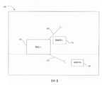
圖1展示根據一項所圖解說明之實施例之一機器人102可在其中操作之一操作環境100。為了簡潔起見,操作環境100在本文中稱為環境100。該環境表示機器人102可在其中操作及移動之一個二維或三維空間。機器人102可係任何類型之機器人,包含但不限於:笛卡耳座標系、選擇性機器人組裝柔性臂(SCARA)、圓柱座標系、三角座標系、極座標系及垂直關節連接型。機器人亦可係可自主或半自主地(亦即,至少部分自主)操作且在由環境100表示之空間中移動之一汽車、飛機、無人飛行器或任何其他運載工具。環境100係二維或三維空間,機器人在其中操作且不同於下文關於圖4A及圖4B之動作規劃圖像所提及且如在以下申請案中所解釋之機器人之「組態空間」(通常稱為「C空間」):於2017年6月9日提出申請的標題為「MOTION PLANNING FOR AUTONOMOUS VEHICLES AND RECONFIGURABLE MOTION PLANNING PROCESSORS」之國際專利申請案第PCT/US2017/036880號,該申請案之全文藉此以引用方式併入;及於2016年1月5日提出申請的標題為「SPECIALIZED ROBOT MOTION PLANNING HARDWARE AND METHODS OF MAKING AND USING SAME」之國際專利申請公開案第WO 2016/122840號,該公開案之全文亦藉此以引用方式併入。組態空間通常係諸多維度的(亦即,大於3個維度)。特定而言,規劃圖像之每一節點表示機器人之一狀態,其可包含但不限於機器人之一特定組態(此係機器人之一組特定關節位置之完整規範)、機器人之姿勢、速度及前進方向。規劃圖像之每一邊緣表示機器人自一個狀態至另一狀態之一轉變。Figure 1 shows an
參考圖1,環境100可包含障礙物碰撞區域。此等障礙物碰撞區域可歸因於環境100中之靜態物件(例如,垃圾箱、容器、柱子、架子、建築物、樹、岩石、家具)或動態物件(例如,其他機器人、運載工具、人)。舉例而言,障礙物A 112及障礙物B 104表示在環境100中形成碰撞區域之物件,使得若機器人102嘗試在與障礙物A 112或障礙物B 104相同之時間處在環境100內佔用相同空間,則機器人102與障礙物A 112或障礙物B 104碰撞係可能的。在各種實施例中,可存在比圖1中所展示的物件更少或額外之物件。Referring to FIG. 1, the
另外,通常存在基於機器人自身之幾何結構以及機器人之數目、位置及移動自由度而置於機器人之移動或姿勢上之運動約束。In addition, there are usually motion constraints placed on the movement or posture of the robot based on the geometric structure of the robot itself and the number, position, and freedom of movement of the robot.
動作規劃之挑戰涉及以一相對低成本但以極快速速度執行動作規劃之能力。此涉及的係對被視為由機器人102佔用之空間以及環境100中之障礙物進行有效表示、傳達及比較之挑戰。舉例而言,如圖1中所展示,障礙物A 112當前係在機器人102之前方。有利的係,機器人102能夠快速並有效地判定機器人臂106之哪些移動(及機器人102之任何移動)將導致與障礙物A 112之一碰撞。因此,本發明提供產生動作規劃圖像、路線圖或網格以允許使機器人102 (包含自主運載工具)在由機器人102及一或多個障礙物A 112佔用之一環境100中操作之動作規劃的解決方案。特定而言,一最終使用者可規定一或多個姿勢,且一系統或應用可有利地自動或自主地判定一或多個自主地產生之額外姿勢以及姿勢之間的邊緣。系統或應用可有利地自動或自主地執行姿勢及邊緣之運動檢查及碰撞檢查。The challenge of motion planning involves the ability to perform motion planning at a relatively low cost but extremely fast. This involves the challenge of effectively representing, communicating, and comparing the space considered to be occupied by the
雖然圖1圖解說明一代表性環境100,但典型環境可包含諸多額外物件及實體,包含對應於其他機器人之物件以及各種其他天然或人工靜態及動態物件及障礙物。本文中所教示之概念可以一類似方式用於比所圖解說明之環境更稠密之一環境。Although FIG. 1 illustrates a
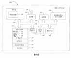
圖2及以下論述提供對一適合的基於處理器之系統200之一簡潔大體說明,其中可根據一項所圖解說明之實施例來實施各種所圖解說明及所闡述動作規劃系統及方法。Figure 2 and the following discussion provide a concise general description of a suitable processor-based
儘管並非需要,但該等實施例中之諸多者將在電腦可執行指令之一般內容脈絡中闡述,諸如儲存在電腦或處理器可讀媒體上且由可執行碰撞評估及動作規劃操作之一或多個電腦或處理器執行之程式應用模組、物件或巨集。此等動作規劃操作可包含但不限於以下各項中之一或多者:產生與規劃圖像之邊緣相關聯之機器人掃掠體積之一個或多個離散化表示;判定將使用若干個離散化中之哪一個來產生機器人掃掠體積之離散化表示;產生機器人102將在其中操作之環境之離散化表示,包含環境中之障礙物;判定使用若干個離散化中之哪一個來產生環境之一離散化表示;判定複數個規劃圖像;儲存所判定複數個規劃圖像及各別組邊緣資訊;產生表示在由規劃圖像之節點表示之狀態之間轉變中由機器人102之至少一部分掃掠之一體積之資訊;對一規劃圖像之邊緣執行一碰撞評估;提供用於規劃圖像之若干組邊緣資訊;自規劃圖像識別一或多個最佳化結果;對與規劃圖像之邊緣相關聯之掃掠體積之離散化表示與機器人102將在其中操作之環境中之障礙物之離散化表示之間的碰撞進行碰撞檢查;判定最佳化是否產生機器人102之任何無碰撞路徑;及實施機器人102之一動作規劃。Although not required, many of these embodiments will be described in the context of the general content of computer-executable instructions, such as stored on a computer or processor-readable medium and executed by one of collision assessment and motion planning operations or Program application modules, objects, or macros executed by multiple computers or processors. These motion planning operations may include, but are not limited to, one or more of the following: generating one or more discretized representations of the robot sweep volume associated with the edge of the planned image; determining that several discretizations will be used Which one to generate the discretized representation of the sweeping volume of the robot; generate the discretized representation of the environment in which the robot 102 will operate, including obstacles in the environment; determine which of several discretizations to use to generate the environment A discretized representation; determine a plurality of planning images; store the determined plurality of planning images and each group of edge information; generate representations that are scanned by at least a part of the robot 102 during the transition between the states represented by the nodes of the planning images Scan a volume of information; perform a collision assessment on the edge of a planning image; provide several sets of edge information for the planning image; identify one or more optimization results from the planning image; compare the planning image The collision between the discretized representation of the swept volume associated with the edge of the robot 102 and the discretized representation of the obstacle in the environment in which the robot 102 will operate is checked for collision; it is determined whether the optimization produces any collision-free path of the robot 102 ; And implement a motion plan of the robot 102.
圖1之機器人102具有將感知資料發送至一或多個處理器(諸如處理器212a)之感測器,諸如圖2中所展示之感測器282。可將感知資料提供為在當前環境中佔用之體素或方塊或其他表示之一串流。此資料係由一或多個處理器(諸如一處理器212a)產生(或提供至一或多個處理器),呈一佔用柵格或其他數位表示之形式。特定而言,當表示環境100中之一機器人或一物件(例如,一障礙物)時,可將其等表面表示為體素(3D像素)或多邊形(通常三角形)網目。空間之每一離散化區域稱為一「體素」,等效於一個3D(體積)像素。在某些情形中,有利的係,將物件替代地表示為方塊(矩形稜柱)。歸因於物件並非隨機形狀之事實,可存在如何組織體素之一顯著量之結構;一物件中之諸多體素在3D空間中緊挨著彼此。因此,將物件表示為方塊可需要少得多之位元(亦即,針對方塊之兩個對置隅角可僅需要x、y、z笛卡耳座標)。而且,對方塊進行相交測試在複雜性上堪比對體素進行如此測試。The
諸多實施例可組合多個感測器之輸出且該等感測器可提供一極精細粒度體素化。然而,為了使機器人102有效執行動作規劃,機器人102之處理器212a可使用較粗略體素(亦即,「處理器體素」)來表示環境及由機器人102在各種狀態之間進行轉變時掃掠之3D空間中之體積。因此,系統200可相應地變換感測器282之輸出。舉例而言,感測器282之輸出可在每一軸上使用10位元之精度,因此直接源自感測器282之每一個體素(亦即,一「感測器體素」)具有一個30位元ID,且存在230個感測器體素。系統200針對一個18位元處理器體素ID在每一軸上使用(在設計時間及運行時間處) 6位元之精度且存在218個處理器體素。因此存在每處理器體素212個感測器體素。在運行時間處,若系統200判定一處理器體素內之感測器體素中之任一者被佔用,則系統200將處理器體素視為被佔用之且相應地產生佔用柵格或其他表示。Many embodiments can combine the outputs of multiple sensors and the sensors can provide a very fine-grained voxelization. However, in order for the
機器人102之一規劃圖像之每一邊緣亦具有某一數目之體素(或方塊),其等對應於由機器人102在進行由彼邊緣表示之於規劃圖像中自一個狀態至另一狀態之轉變時掃掠之3D空間中之體積。由機器人102在進行由彼邊緣表示之於規劃圖像中自一個狀態至另一狀態之轉變時掃掠之彼等體素或方塊可針對規劃圖像之每一邊緣儲存在專用於規劃圖像之晶片外記憶體中,諸如儲存在規劃圖像邊緣資訊記憶體284中。在各種其他實施例中,由機器人102在進行由彼邊緣表示之於規劃圖像中自一個狀態至另一狀態之轉變時掃掠之體素或方塊可針對規劃圖像之每一邊緣儲存在其他位置中,諸如(舉例而言)儲存在一或多個特殊應用積體電路(ASIC)中之單晶片記憶體中之。Each edge of a planning image of the
在一項實施例中,藉由首先將全部障礙物體素(或方塊)流式輸入至處理器(諸如處理器212a)上來執行碰撞評估。舉例而言,可將表示環境100之障礙物體素(或方塊)(包含障礙物A 112及障礙物B 104)流式輸入至處理器212a中且儲存在環境記憶體294上。環境記憶體294係處理器212a之單晶片記憶體。在某些實施例中,環境記憶體294可係一場可程式化閘陣列(FPGA)中之區塊RAM (BRAM)。在某些實施例中,BRAM可係含有隨機存取記憶體(RAM)之數個千位元之一專用可組態兩端口記憶體單元。FPGA含有此等區塊中之數個。然後,自專用於規劃圖像之晶片外記憶體(諸如自規劃圖像邊緣資訊記憶體284)流式傳輸機器人102之規劃圖像之每一邊緣之邊緣資訊。對於每一邊緣體素(或方塊),當其係自一邊緣之掃掠體積流式輸入時,若其與障礙物體素(或方塊)中之任一者碰撞,則處理器212a判定與規劃圖像中之彼邊緣之一碰撞。In one embodiment, the collision assessment is performed by first streaming all obstacle objects (or blocks) to a processor (such as the
舉例而言,當自規劃圖像之邊緣x之掃掠體積流式輸入一邊緣體素時,處理器212a可使用布林(Boolean)電路來比較該邊緣體素與儲存在環境記憶體294上之全部障礙物體素(或方塊)。若系統200基於該比較而判定邊緣體素與障礙物體素(或方塊)中之任一者碰撞,則系統200備註與邊緣x之一碰撞。與其中對規劃圖像之全部邊緣並行執行碰撞評估之其他設計相比,此實施例改良碰撞評估之技術,此乃因其使得能夠在碰撞評估中使用更大規劃圖像。特定而言,此幫助克服關於處理器晶片電路上可儲存一有限量規劃圖像資訊之其他設計之缺點。使用本文中所闡述之碰撞評估方法,諸如環境記憶體294之單晶片儲存器通常更足以儲存全部障礙物方塊(儘管在使用體素時單芯片儲存器可係較不充足)。此提供在較不昂貴晶片外儲存器中儲存大規劃圖像及/或多個規劃圖像之能力。舉例而言,此提供在規劃圖像邊緣資訊記憶體284中儲存大規劃圖像及/或多個規劃圖像之能力,在某些實施例中規劃圖像邊緣資訊記憶體284係一較不昂貴類型之記憶體,諸如動態隨機存取記憶體(DRAM)。For example, when an edge voxel is input from the swept volume flow of the edge x of the planned image, the
在各種實施例中,此等操作可完全在硬體電路中或作為儲存在一記憶體儲存器(諸如系統記憶體214)中且由一或多個硬體處理器212a (諸如一或多個微處理器、數位信號處理器(DSP)、場可程式化閘陣列(FPGA)、特殊應用積體電路(ASIC)、圖像處理單元(GPU)處理器、經程式化邏輯控制器(PLC)、電可程式化唯讀記憶體(EEPROM))執行之軟體或作為硬體電路與儲存在記憶體儲存器中之軟體之一組合來執行。In various embodiments, these operations may be entirely in the hardware circuit or as stored in a memory storage (such as system memory 214) and executed by one or
而且,感知、規劃圖像構造、碰撞偵測及路徑搜尋之各種相關態樣之實施方案亦闡述於以下申請案中:於2017年6月9日提出申請的標題為「MOTION PLANNING FOR AUTONOMOUS VEHICLES AND RECONFIGURABLE MOTION PLANNING PROCESSORS」之國際專利申請案第PCT/US2017/036880號、於2016年1月5日提出申請的標題為「SPECIALIZED ROBOT MOTION PLANNING HARDWARE AND METHODS OF MAKING AND USING SAME」之國際專利申請公開案第WO 2016/122840號及於2018年1月12日提出申請的標題為「APPARATUS, METHOD AND ARTICLE TO FACILITATE MOTION PLANNING OF AN AUTONOMOUS VEHICLE IN AN ENVIRONMENT HAVING DYNAMIC OBJECTS」之美國專利申請案第62/616,783號,且其等全文以引用方式併入本文中。熟習此項技術者將瞭解,所圖解說明之實施例以及其他實施例可藉助其他系統結構及配置及/或其他計算系統結構及配置來實踐,包含機器人、手持式裝置、多處理器系統、基於微處理器之或可程式化消費型電子器件、個人電腦(「PC」)、網路型PC、迷你型電腦、大型電腦及諸如此類中之彼等。實施例或其部分(例如,在設計時間及預運行時間處)可在分散式計算環境中實踐,其中任務或模組係由經由一通信網路連結之遠端處理裝置執行。在一分散式計算環境中,程式模組可位於本端及遠端記憶體儲存裝置或媒體兩者中。然而,某些類型之資訊儲存在何處及如何儲存對幫助改良動作規劃係重要的。Moreover, the implementation of various related aspects of perception, planning image construction, collision detection and path search are also described in the following application: The application filed on June 9, 2017 is entitled "MOTION PLANNING FOR AUTONOMOUS VEHICLES AND RECONFIGURABLE MOTION PLANNING PROCESSORS” International Patent Application No. PCT/US2017/036880, and an international patent application published on January 5, 2016 titled “SPECIALIZED ROBOT MOTION PLANNING HARDWARE AND METHODS OF MAKING AND USING SAME” WO 2016/122840 and the U.S. Patent Application No. 62/616,783 entitled "APPARATUS, METHOD AND ARTICLE TO FACILITATE MOTION PLANNING OF AN AUTONOMOUS VEHICLE IN AN ENVIRONMENT HAVING DYNAMIC OBJECTS" filed on January 12, 2018 , And its full text is incorporated herein by reference. Those familiar with the art will understand that the illustrated embodiments and other embodiments can be practiced with the aid of other system structures and configurations and/or other computing system structures and configurations, including robots, handheld devices, multi-processor systems, and Microprocessors or programmable consumer electronic devices, personal computers ("PCs"), networked PCs, mini computers, mainframe computers and the like. The embodiments or parts thereof (for example, at design time and pre-run time) can be practiced in a distributed computing environment, where tasks or modules are executed by remote processing devices connected via a communication network. In a distributed computing environment, program modules can be located in both local and remote memory storage devices or media. However, where and how certain types of information are stored are important to help improve action planning.
舉例而言,各種動作規劃解決方案將一路線圖(亦即,一規劃圖像)「烘烤」至處理器中,且路線圖中之每一邊緣對應於處理器之一非可重新組態布林電路。其中將規劃圖像「烘烤」至處理器中之設計造成具有有限處理器電路來儲存多個或大規劃圖像之一問題。For example, various motion planning solutions "bake" a road map (ie, a planning image) into the processor, and each edge of the road map corresponds to a non-reconfigurable processor Bollinger circuit. Among them, the design of "baking" the planning image into the processor causes one of the problems of having a limited processor circuit to store multiple or large planning images.
一個解決方案提供將規劃圖像資訊放置至記憶體儲存器中之一可重新組態設計。藉助此一解決方案,再次存在用於規劃圖像之每一邊緣之資訊,但此資訊係儲存在記憶體中而非烘烤至一電路中。每一邊緣對應於機器人102之一動作,且每一動作掃掠3D空間中之一體積。此掃掠體積與某一數目之障礙物體素(或方塊,或然而其在各種實施例中可經決策以表示障礙物)碰撞。藉助此一解決方案,此邊緣與其碰撞之體素係儲存在記憶體中之資訊。One solution provides that the planning image information is placed in one of the memory storages to reconfigure the design. With this solution, there is again information used to plan each edge of the image, but this information is stored in memory rather than baked into a circuit. Each edge corresponds to an action of the
在某些實施方案中,系統或應用可在運行時間處在多個規劃圖像之間提供動態切換(亦即,重新組態處理器)。舉例而言,考量具有可抓握物件之一末端執行器之一機器人。機器人臂在固持某物時比不固持某物時與3D空間之不同部位碰撞。一項實例係機器人臂106藉助末端執行器將一大球固持在臂之端處。若機器人102正固持某物,則對應於機器人102「未固持任何物品」時之規劃圖像不起作用。相反地,即使機器人102未固持任何物品,亦可極保守地使用「固持某物」規劃圖像,但彼既係無效率的且將需要使用對應於其中機器人102正固持最大可能物件之情景之一單個規劃圖像。而是,在各種實施例中,系統200構建對應於不同可能特性(例如,「未固持任何物品」、「固持大小x之一小球體」、「固持大小y之一矩形稜柱」等)之規劃圖像之一族系。當機器人102拾取物品並將其等放下時,此等規劃圖像可藉由處理器212a自規劃圖像邊緣資訊記憶體284調入及調出。此解決方案亦適用於其末端執行器隨時間改變之一機器人。舉例而言,機器人102可處於具有擁有一第一組尺寸之一第一末端執行器之一配置中。此第一末端執行器可調換為具有一第二組尺寸之一第二末端執行器。當第一末端執行器調換為具有一第二組尺寸之一第二末端執行器時,機器人102將處於具有第二末端執行器之一不同配置中。在第二組尺寸中之尺寸不同於第一組尺寸中之尺寸的情況下,當調換末端執行器時由機器人掃掠之體積改變。亦舉例而言,在機器人係一自主或部分自主運載工具的情況下,運載工具可在一第一週期期間在一第一配置中具有一第一組尺寸,且同一運載工具可在一第二週期期間在一第二配置中具有一第二組尺寸。舉例而言,一運載工具可在一第一配置中係空的且在一第二配置中係滿載的,從而改變運載工具之重量且潛在地改變運載工具在一道路上方之一高度、在運載工具下方之一間隙或甚至一運載工具之一軌跡,舉例而言當其圍繞一轉彎或彎道拐彎時。在第二組尺寸中之尺寸不同於第一組尺寸中之尺寸的情況下,由運載工具掃掠之體積在第一與第二配置之間改變。同樣地,在軌跡在第一與第二配置之間改變的情況下,由運載工具掃掠之體積在該等配置之間改變。因此,系統200將不同規劃圖像儲存在規劃圖像邊緣資訊記憶體284中以用於不同末端執行器。In some embodiments, the system or application can provide dynamic switching between multiple planning images at runtime (ie, reconfigure the processor). For example, consider a robot with an end effector that can grasp an object. The robot arm collides with different parts of the 3D space when holding something than when not holding something. One example is that the
可提前產生規劃圖像,舉例而言,在於運行時間之前之一組態時間期間。一旦產生規劃圖像,則其等可全部儲存在規劃圖像邊緣資訊記憶體284中,且對於處理器212a將其等調入及調換出或基於機器人102之當前特性(諸如當機器人正抓握一特定大小之一物件時)選擇使用哪個係相對快速且有效的。The planning image can be generated in advance, for example, during a configuration time period before the runtime. Once the planning image is generated, it can all be stored in the planning image
如上文所述,可在運行時間之前執行某些預處理活動,且因此,在某些實施例中,此等操作可由透過一通信網路經由網路介面260連結至基於處理器之系統200之遠端處理裝置執行。舉例而言,一程式化階段允許針對所關注問題準備機器人。在此等實施例,利用廣泛預處理來避免運行時間計算。可將關於由機器人102在進行由規劃圖像中之邊緣表示之在路線圖中自一個狀態至另一狀態之轉變時掃掠3D空間中之體積的經預計算資料儲存在規劃圖像邊緣資訊記憶體284中且在運行時間期間由處理器212a存取。系統200亦可在運行時間之前構建規劃圖像之一族系,其對應於可在運行時間期間發生之機器人之不同的可能改變之尺寸特性。然後,系統200將此等規劃圖像儲存在規劃圖像邊緣資訊記憶體284中。As described above, certain pre-processing activities can be performed before runtime, and therefore, in certain embodiments, these operations can be connected to the processor-based
在運行時間階段期間,感測器282將感知資料發送至處理器212a。感知資料可係存在於當前環境中且儲存在單晶片環境記憶體294中之體素或方塊之一串流。使用布林電路來比較自環境記憶體294擷取之感知資料與儲存在規劃圖像邊緣資訊記憶體284中之資訊,處理器212a計算哪些動作避免碰撞且選擇規劃圖像中之一對應路徑以使機器人102依循。然後,處理器212a運行並將所得路徑傳回至致動器系統266。During the runtime phase, the
圖2展示一基於處理器之系統200 (諸如用於機器人102之基於處理器之系統),其包括由處理器212a表示之一或多個處理器及一或多個相關聯非暫時性機器可讀儲存媒體,諸如系統記憶體214、規劃圖像邊緣資訊記憶體284及與磁碟機224相關聯之電腦可讀媒體226。相關聯非暫時性電腦或處理器可讀儲存媒體(包含系統記憶體214、規劃圖像邊緣資訊記憶體284及與磁碟機224相關聯之電腦可讀媒體226)經由一或多個通信頻道(諸如系統匯流排216)通信地耦合至處理器212a。系統匯流排216可採用任何已知匯流排結構或架構,包含具有記憶體控制器之一記憶體匯流排、一周邊匯流排及/或一本端匯流排。一或多個感測器282及一致動器系統266亦經由系統匯流排216通信地耦合至處理器212a。此等組件中之一或多者亦可或替代地經由一或多個其他通信頻道(舉例而言,一或多個並行電纜、串列電纜或能夠高速通信之無線網路頻道(舉例而言,通用串列匯流排(「USB」) 3.0、高速周邊組件互連(PCIe)))或經由Thunderbolt®彼此通信。Figure 2 shows a processor-based system 200 (such as the processor-based system used in the robot 102), which includes one or more processors represented by the
基於處理器之系統200亦可通信地耦合至遠端系統,例如,桌上型電腦、膝上型電腦、超可攜式電腦、平板電腦、智慧型電話、可穿戴電腦(未展示),其等直接通信地耦合至或經由網路介面260間接通信地耦合至基於處理器之系統200之各種組件。此等遠端系統可用於對基於處理器之系統200及基於處理器之系統200內之各種組件進行程式化、組態、控制或以其他方式與其等介接或將資料輸入至其等。此一連接可係透過一或多個通信頻道,舉例而言,使用網際網路協定之一或多個廣域網路(WAN),舉例而言,網際網路。如上文所述,預運行時間計算(例如,規劃圖像之族系之產生)可由與機器人102或其他機器人分離之一系統執行,而運行時間計算可在係在機器人102上之處理器212上執行,此乃因重要的係系統200能夠改變規劃圖像以即時地對機器人102之改變之實體尺寸做出反應。The processor-based
除非另有闡述,否則圖2中所展示之各種區塊之構造及操作係為習用設計或闡述於以下申請案中:於2017年6月9日提出申請的標題為「MOTION PLANNING FOR AUTONOMOUS VEHICLES AND RECONFIGURABLE MOTION PLANNING PROCESSORS」之國際專利申請案第PCT/US2017/036880號;於2016年1月5日提出申請的標題為「SPECIALIZED ROBOT MOTION PLANNING HARDWARE AND METHODS OF MAKING AND USING SAME」之國際專利申請公開案第WO 2016/122840號;及/或於2018年1月12日提出申請的標題為「APPARATUS, METHOD AND ARTICLE TO FACILITATE MOTION PLANNING OF AN AUTONOMOUS VEHICLE IN AN ENVIRONMENT HAVING DYNAMIC OBJECTS」之美國專利申請案第62/616,783號,且其等全文以引用方式併入本文中。因此,此等區塊無需進一步詳細闡述,此乃因鑒於以引用方式併入本文中熟習此項技術者將理解此等區塊。Unless otherwise stated, the structure and operation of the various blocks shown in Figure 2 are conventional designs or are described in the following applications: The application filed on June 9, 2017 is titled "MOTION PLANNING FOR AUTONOMOUS VEHICLES AND RECONFIGURABLE MOTION PLANNING PROCESSORS" International Patent Application No. PCT/US2017/036880; International Patent Application Publication of "SPECIALIZED ROBOT MOTION PLANNING HARDWARE AND METHODS OF MAKING AND USING SAME" filed on January 5, 2016 WO 2016/122840; and/or U.S. Patent Application No. 62 entitled "APPARATUS, METHOD AND ARTICLE TO FACILITATE MOTION PLANNING OF AN AUTONOMOUS VEHICLE IN AN ENVIRONMENT HAVING DYNAMIC OBJECTS" filed on January 12, 2018 No. /616,783, and the entire contents thereof are incorporated herein by reference. Therefore, these blocks do not need to be elaborated further, because those familiar with the technology will understand these blocks in view of the fact that they are incorporated herein by reference.
基於處理器之系統200可包含一或多個處理單元212、系統記憶體214、規劃圖像邊緣資訊記憶體284及系統匯流排216,該系統匯流排將包含系統記憶體214及規劃圖像邊緣資訊記憶體284之各種系統組件耦合至處理單元212。在某些實施例中,規劃圖像邊緣資訊記憶體284可係系統記憶體214或其部分。該等處理單元可係任何邏輯處理單元,諸如一或多個中央處理單元(CPU) 212a、數位信號處理器(DSP) 212b、特殊應用積體電路(ASIC)、場可程式化閘陣列(FPGA)等。系統記憶體214可包含唯讀記憶體(「ROM」) 218及隨機存取記憶體(「RAM」) 220。規劃圖像邊緣資訊記憶體284可包含RAM,諸如DRAM。可形成ROM 218之部分之一基本輸入/輸出系統(「BIOS」) 222含有幫助諸如在起動期間在基於處理器之系統200內之元件之間傳送資訊之基本常式。The processor-based
基於處理器之系統200可包含一磁碟機224,舉例而言,其可係:用於自一硬碟讀取及寫入至一硬碟之一硬碟驅動器、用於自可移除快閃記憶體裝置讀取及寫入至可移除快閃記憶體裝置之一快閃記憶體驅動器、用於自可移除光碟讀取及寫入至可移除光碟之一光碟驅動器或用於自磁碟讀取及寫入至磁碟之一磁碟機。在各種不同實施例中,基於處理器之系統200亦可包含此等磁碟機之任一組合。磁碟機224可經由系統匯流排216與處理單元212通信。磁碟機224可包含耦合在此等驅動器與系統匯流排216之間之介面或控制器(未展示),如熟習此項技術者所知曉。磁碟機224及其相關聯電腦可讀媒體226提供基於處理器之系統200之電腦可讀指令、資料結構、程式模組及其他資料之非揮發性儲存。熟習此項技術者將瞭解,可採用可儲存可由一電腦存取之資料之其他類型之電腦-可讀媒體,諸如WORM驅動器、RAID驅動器、磁帶盒、數位視訊碟片(「DVD」)、伯努利(Bernoulli)卡匣、RAM、ROM、智慧卡等。The processor-based
程式模組可儲存在系統記憶體214中,諸如一作業系統236、一或多個應用程式238、其他程式或模組240及程式資料242。應用程式238可包含致使處理器212執行以下各項中之一或多者之指令:產生與規劃圖像之邊緣相關聯之機器人掃掠體積之一或多個離散化表示;判定將使用若干個離散化中之哪一個來產生機器人掃掠體積之離散化表示;產生機器人將在其中操作之環境100之離散化表示,包含環境100中之障礙物;判定將使用若干個離散化中之哪一個來產生環境100之一離散化表示;判定複數個規劃圖像;儲存所判定複數個規劃圖像及各別組邊緣資訊;產生表示在由規劃圖像之節點表示之狀態之間之轉變中由機器人之至少一部分掃掠之一體積之資訊;對一規劃圖像之邊緣執行一碰撞評估;提供用於規劃圖像之若干組邊緣資訊;自規劃圖像識別一或多個最佳化結果;對在與規劃圖像之邊緣相關聯之掃掠體積之離散化表示與機器人102將在其中操作之環境100中之障礙物之離散化表示之間之碰撞進行碰撞檢查;判定該最佳化是否產生機器人之任何無碰撞路徑;及實施機器人之一動作規劃。應用程式238可另外包含一或多個機器可讀指令,其等致使處理器212執行感知(經由感測器282)、規劃圖像構造、碰撞偵測及路徑搜尋之其他操作,如本文中及以引用方式併入本文中之參考文獻中所闡述。Program modules may be stored in the
應用程式238可另外包含一或多個機器可讀指令,其等致使處理器212產生表示在對應於當機器人102具有不同尺寸時之狀態之間之轉變中由機器人102掃掠之不同體積的各別組規劃圖像邊緣資訊且對應於各別組規劃圖像邊緣資訊,將複數個規劃圖像儲存在規劃圖像邊緣資訊記憶體284中。The
應用程式238可另外包含一或多個機器可讀指令,其等致使處理器212:針對機器人102將在其中操作之一環境100之一第一離散化表示,供應環境100之第一離散化表示之至少一部分並儲存在環境記憶體294中;針對規劃圖像之每一邊緣,提供一各別組邊緣資訊並儲存在規劃圖像邊緣資訊記憶體284中;及識別對應轉變將導致機器人102之至少一部分與一或多個障礙物(諸如環境100中之障礙物A 112及障礙物B 104)中之至少一者之至少一部分之間的一碰撞之規劃圖像之邊緣中之任一者。The
術語「環境」在本實例中用來指代機器人之當前工作空間,包含障礙物。術語「任務」在本實例中用來指代其中機器人102必須在不與其環境中之障礙物碰撞的情況下自姿勢A變為姿勢B (也許抓握或掉落某物)之一機器人任務。術語「情景」在本實例中用來指代一類別之環境/任務對。舉例而言,一情景可係「在具有一個3英尺桌子之一環境中且在具有一給定範圍中之大小及形狀之x與y障礙物之間之取放任務」。取決於目標位置以及障礙物之大小及形狀,可存在適合於此等準則之諸多不同任務/環境對。系統200可包含經由網路介面260透過一通信網路連結之一或多個遠端處理裝置。此一或多個遠端處理裝置可執行一或多個機器可讀指令,其等致使系統200針對各種不同情景之任務及環境對產生機器人102將在其中操作之一環境100之一表示之一各別離散化。在一實例實施例中,各別離散化中之至少兩者包括一各別組體素。各別離散化之體素在各別離散化內之大小及形狀中之至少一者中可係非均質的。而且,各別離散化之體素之非均質性之一各別分佈可彼此不同。特定而言,該等離散化可包括一各別組體素,其中各別離散化中之至少兩者之體素在各別離散化內之大小及形狀中之至少一者中係非均質的,且各別離散化中之至少兩者之體素之非均質性之一各別分佈彼此不同。應用程式238可包含一或多個機器可讀指令,其等致使處理器212接著評估機器人將在其中操作之環境100之表示之所產生各別離散化之一有效性且儲存對於特定情景評估為最有效之所產生各別離散化。The term "environment" is used in this example to refer to the current workspace of the robot, including obstacles. The term "task" is used in this example to refer to a robot task in which the
應用程式238可另外包含一或多個機器可讀指令,其等致使處理器212:基於分類機器人102將執行之一對任務及機器人將在其中操作之環境100之一所識別情景,判定將使用若干個離散化中之哪一個來產生表示機器人102在於機器人之一個狀態與機器人102之另一狀態之間轉變中將通過之各別區域之若干個掃掠體積;且對於一規劃圖像中之複數個邊緣中之每一者,使用所判定離散化來判定邊緣之一各別掃掠體積。應用程式238可另外包含一或多個機器可讀指令,其等致使處理器212儲存機器人102將在其中操作之環境100之表示之所判定掃掠體積之各別離散化,該等各別離散化評估為對於所識別情景係最有效的。The
應用程式238可另外包含一或多個機器可讀指令,其等致使處理器212至少部分地基於分類機器人102將執行之一對任務及機器人在其中操作之一環境100之一所識別情景,判定將使用若干個離散化中之哪一個來產生環境100之一離散化表示。應用程式238可另外包含一或多個機器可讀指令,其等致使處理器212接收由感測環境100之一或多個感測器282產生之感測器資訊且使用所判定離散化產生環境(包含環境中(若有)之障礙物)之一離散化表示,。所判定離散化之複數個體素在各別離散化內大小及形狀中之至少一者上可係非均質的,且所判定離散化之體素之非均質性之一各別分佈可不同於若干個離散化之另一體素之非均質性之一各別分佈。The
應用程式238可另外包含一或多個機器可讀指令,其等致使處理器212對規劃圖像之邊緣與機器人將在其中操作之一環境中之任何障礙物之間的多個規劃圖像執行碰撞檢查。處理器212可對每一規劃圖像執行此碰撞檢查、相應地暫時更新規劃圖像且執行一最佳化並判定來自經更新規劃圖像之最佳化結果(若有)是否符合一滿足條件。若不符合該滿足條件,則處理器212可移動至下一規劃圖像且執行相同操作。一旦發現其中符合該滿足條件之一規劃圖像,處理器212便將由來自規劃圖像之符合滿足條件之最佳化結果中之一者識別之一轉變施加至機器人102。The
應用程式238可另外包含一或多個機器可讀指令,其等致使處理器212執行本文中所闡述之各種其他方法,包含但不限於圖5及圖6中所圖解說明之彼等。The
在各種實施例中,上文所闡述之操作中之一或多者可由系統200之一或多個遠端處理裝置或由位於機器人102上之一或多個處理器212執行,該等遠端裝置經由網路介面260透過一通信網路而連結。In various embodiments, one or more of the operations described above may be performed by one or more remote processing devices of the
雖然在圖2中展示為儲存在系統記憶體214中,但作業系統236、應用程式238、其他程式/模組240及程式資料242可儲存在磁碟機224之相關聯電腦可讀媒體226上。Although shown in FIG. 2 as being stored in the
處理器212可係任何邏輯處理單元,諸如一或多個中央處理單元(CPU)、數位信號處理器(DSP)、特殊應用積體電路(ASIC)、場可程式化閘陣列(FPGA)等。可商業購得之電腦系統之非限制性實例包含但不限於:由美國Intel®公司提供之Celeron、Core、Core 2、Itanium及Xeon族系之微處理器;由美國超威半導體公司(Advanced Micro Devices)提供之K8、K10、Bulldozer及Bobcat系列微處理器;由美國蘋果電腦提供之A5、A6及A7系列微處理器;由美國高通公司(Qualcomm, Inc.)提供之Snapdragon系列微處理器;及由美國甲骨文公司(Oracle Corp.)提供之SPARC系列微處理器。除非另有闡述,否則圖2中所展示之各種區塊之構造及操作係為習用設計。因此,本文中無需進一步詳細闡述此等區塊,此乃因其等將由熟習此項技術者所理解。The processor 212 may be any logic processing unit, such as one or more central processing units (CPU), digital signal processors (DSP), application-specific integrated circuits (ASIC), field programmable gate array (FPGA), and so on. Non-limiting examples of commercially available computer systems include, but are not limited to: Celeron, Core, Core 2, Itanium, and Xeon family microprocessors providedby Intel ® Corporation; Devices) K8, K10, Bulldozer and Bobcat series microprocessors; A5, A6 and A7 series microprocessors provided by Apple Computer; Snapdragon series microprocessors provided by Qualcomm, Inc.; And SPARC series microprocessors provided by Oracle Corp. of the United States. Unless otherwise stated, the structure and operation of the various blocks shown in FIG. 2 are conventional designs. Therefore, there is no need to further elaborate on these blocks in this article, because they will be understood by those familiar with the technology.
因此,為促進避免碰撞,在設計時間處(在運行時間之前),一或多個規劃圖像係由系統200產生以判定哪些區係由機器人102在自一個狀態至另一狀態進行各種轉變時被佔用。舉例而言,機器人102之一規劃圖像之一邊緣具有對應於由機器人102掃掠之3D空間中之體積之某一數目個體素(或方塊)(對應於區域302)。由機器人102掃掠之彼等體素或區塊(對應於當在規劃圖像中進行對應轉變時之一區域)可儲存為對應於專用於規劃圖像之晶片外記憶體中(諸如規劃圖像邊緣資訊記憶體284中)之規劃圖像之一邊緣。然後,在運行時間處,以一佔用柵格或其他表示之形式將表示環境100 (包含障礙物A 112 (且亦障礙物B 104))之障礙物體素(或方塊)提供(例如,流式傳輸)至處理器212a且儲存在單晶片環境記憶體294上。系統200判定哪些體素被佔用(基於佔用柵格或其他表示),且判定不使用將與任何當前所佔用體素碰撞之任何動作。特定而言,對於表示一邊緣之掃掠體積之一部分之每一邊緣體素(或方塊),當其自規劃圖像邊緣資訊記憶體284流式輸入時,處理器基於佔用柵格或其他表示而判定其是否與已儲存在環境記憶體294中之障礙物體素(或方塊)中之任一者碰撞。若邊緣體素(或方塊)與障礙物體素(或方塊)中之任一者碰撞,則系統200判定與規劃圖像中之彼邊緣之一碰撞且將判定不使用與規劃圖像中之彼邊緣相關聯之機器人102之動作。Therefore, in order to facilitate collision avoidance, at design time (before running time), one or more planning images are generated by the
舉例而言,在執行圖1中所繪示之機器人臂106之動作之前,系統200將開始自規劃圖像邊緣記憶體284流式輸入適用規劃圖像之全部邊緣之邊緣體素(或方塊)。對於每一邊緣,當處理器212a遭遇每一邊緣體素(或方塊)時,其將檢查以查看任一邊緣體素(或方塊)是否與儲存在環境記憶體294中之障礙物體素(或方塊)中之任一者碰撞(包含障礙物A 112之彼等)。掃掠區域內之任何邊緣體素(或方塊)將導致此一碰撞,此乃因儲存在環境記憶體294中之障礙物A 112之障礙物體素(或方塊)根據佔用柵格或其他表示而佔用彼同一區域。處理器212a一遭遇與障礙物體素(或方塊)中之任一者碰撞之一邊緣體素(或方塊),處理器212a便接著判定不使用規劃圖像之彼邊緣。一旦完成處理規劃圖像之邊緣,處理器212a便判定規劃圖像內之一路徑,該路徑將致使機器人使用尚未判定與儲存在環境記憶體294中之障礙物體素(或方塊)碰撞之剩餘邊緣而自初始位置移動至目標位置。For example, before executing the action of the
系統200亦可做出關於如何表示由規劃圖像中之每一者表示之掃掠體積以及如何表示環境100中之障礙物的決策。此等決策可包含由處理器212a做出的關於將如何執行離散化之決策,諸如(舉例而言),是否表示具有體素或方塊之掃掠體積、待使用之體素或方塊之形狀及大小,是否使用在所使用之體素或方塊之大小及/或形狀上係非均勻之一離散化及在哪些情景中使用體素或方塊之不同形狀及/或大小。在各種實施例中,上文所闡述的做出關於如何表示由規劃圖像中之每一者表示之掃掠體積以及如何表示環境100中之障礙物之決策之此等操作中之一或多者可由系統200之一或多個遠端處理裝置或由位於機器人102上之一或多個處理器212執行,該等遠端處理裝置經由網路介面260透過一通信網路而連結。The
特定而言,系統200可決策將機器人102之工作空間離散化成體素(其稍後可分組為方塊)。一項實例實施方案在3個維度中之每一者中執行均勻量化。然而,可有利地具有在機器人之工作空間之不同部位中較小/較大之非立方體形狀之體素及/或體素。舉例而言,一項實施例在機器人102之正前方之空間中使用較小體素(較精細解析度)且在機器人可達範圍之最末端處使用較大體素(較粗略解析度)。因此,各種實施例可使用非均勻量化及/或使用非立方體形狀之體素。本發明亦提供關於系統200如何選擇體素大小及/或形狀之一演算法。In particular, the
一項實例實施例使用一訓練演算法以在運行時間之前執行以判定哪些體素大小及形狀可較佳用於各種不同情景。可藉由使用來自一或多個情景之一大組給定或所產生任務/環境對來訓練系統200。系統200然後選擇在大組訓練樣本內評估為最有效之離散化。An example embodiment uses a training algorithm to be executed before runtime to determine which voxel sizes and shapes are better for various different scenarios. The
舉例而言,對於任何環境/任務對,存在一最佳離散化(或同等最佳之多個離散化)。系統200可對T環境/任務對進行測試/訓練,其中T係一大數目,且接著記錄每一者之最佳離散化。此可導致諸多不同離散化,其每一者對於僅一個或一小數目個環境/任務對係最佳的。在測試全部T環境/任務對之後,系統選擇在整組樣本內被評估為最有效之離散化。此方法亦將涉及對每一可能環境/任務對嘗試每一可能離散化,此將係難以解決的。For example, for any environment/task pair, there is an optimal discretization (or equally optimal multiple discretizations). The
為克服上文問題,系統200執行類似於上文所解釋之訓練,除了系統200考量有限數目之可能離散化G之外。對於每一環境/任務對,系統皆記錄所提供之G離散化中之哪一個被評估為最有效的。在處理全部T環境/任務對之後,系統200選擇在大多數環境/任務對中被評估為最有效之離散化。To overcome the above problems, the
作為一實例,機器人102可正面對在其前方之空間之一方塊。該系統可判定將空間離散化,使得6個位元用於闡述每一維度中之位置(亦即,在每一軸上存在26個可能位置)。此導致218個體素,其每一者具有一唯一18位元ID。在設計時間處,系統200預先計算每一邊緣之動作之掃掠體積,且將其記錄為在彼掃掠體積中之體素ID之集合。若掃掠體積甚至部分地與一個體素相交,則其包含於彼掃掠體積中之體素ID之集合中。此係為什麼使用一較精細解析度係較佳的。然後,在運行時間處,感測器282告知處理器212a何物係在機器人102之前方,但以比表示經預先計算之掃掠體積之體素精細得多之一粒度,因此系統200處理感測器輸入且將體素中之哪一些當前被佔用傳達至處理器212a。在某些實施例中,處理器212a處理感測器輸入,且在其他實施例中,存在單獨處理器(諸如感測器282中之彼等),其處理感測器輸入且傳達至處理器212a。處理器212a將基於儲存在環境記憶體294中之資訊當前在環境中之體素或方塊與針對儲存在規劃圖像邊緣資訊記憶體284中之規劃圖像邊緣資訊之每一邊緣所列出之體素或方塊進行比較以判定哪些邊緣當前處於碰撞中。在此等實施例中,重要的係,在設計時間處使用與在運行時間處相同之離散化以便使得能夠進行比較。As an example, the
當系統200選擇使用非均勻離散化時,系統200仍可使用18位元體素ID及218個體素,但體素無需為立方體(或其等可係立方體但並非全部為相同大小)。再一次,在此實施例中重要的係,該系統在設計時間處使用與在運行時間處相同的離散化。當使用一非均勻離散化時,系統200使用諸如上文所闡述彼訓練之訓練來選擇每一個體素之大小及形狀是什麼,使得該系統挑選將在設計時間處及運行時間處使用之被評估為最有效之體素大小及形狀。在此訓練中使用之評估準則可包含關於可解決之任務之分率(例如,系統200可找到某一無碰撞路徑以實現機器人102之目標)及所找到之路徑之品質之準則。When the
一動作規劃圖像或路線圖工具組允許形成或產生由一動作規劃器(例如,即時機器人動作規劃加速器及快速感測空間感知系統)使用之一動作規劃圖像(本文中可互換地稱為一路線圖或路線圖檔案)。該動作規劃圖像工具組被實施為儲存在一或多個非暫時性電腦或處理器可讀媒體上之一組處理器可執行指令或應用(例如,軟體及/或韌體)。該動作規劃圖像工具組提供一直觀使用者介面,舉例而言一直觀圖像使用者介面(GUI)。該應用允許一最終使用者與一機器人之一數位或虛擬模型及機器人將在其中操作之一操作環境之一數位或虛擬表示(本文中可互換地稱為一工作單元)互動以產生或形成經運動檢查及經碰撞檢查之動作規劃圖像或路線圖。An action planning image or roadmap tool set allows for the formation or generation of an action planning image (referred to interchangeably herein as an action planner) used by an action planner (e.g., real-time robot action planning accelerator and fast-sensing spatial perception system) A road map or road map file). The action planning image tool set is implemented as a set of processor-executable instructions or applications (for example, software and/or firmware) stored on one or more non-transitory computer or processor-readable media. The action planning image tool set provides an intuitive user interface, for example, an intuitive graphical user interface (GUI). This application allows an end user to interact with a digital or virtual model of a robot and a digital or virtual representation of an operating environment in which the robot will operate (herein interchangeably referred to as a work unit) to generate or form a Movement check and collision check action planning image or route map.
緊接著在下文初始提供高階概念中之某些概念之一概述以便促進對系統、應用、使用者介面及操作之理解。Next, an overview of some of the high-level concepts is initially provided below in order to promote the understanding of the system, applications, user interfaces, and operations.
一專案係動作規劃圖像或路線圖工具組中之一頂層容器。每一專案含有一組經命名工作空間、一組中樞(Hub)、一組路線圖區域及體素區域。A project is one of the top-level containers in the action planning image or roadmap tool set. Each project contains a set of named workspaces, a set of hubs, a set of roadmap areas and voxel areas.
一工作空間表示一機器人在一環境中之一特定實體組態。對將導致與周圍工作單元或自身之不同碰撞可能性的機器人之實體組態之任何修改應被視為一單獨工作空間。因此,即使一環境中之全部障礙物保持固定,一機器人之一實體特性自一第一工作空間之彼特性之一改變對應於一單獨第二工作空間。A workspace represents a specific physical configuration of a robot in an environment. Any modification to the physical configuration of the robot that will cause a different possibility of collision with the surrounding work cell or itself shall be treated as a separate working space. Therefore, even if all obstacles in an environment remain fixed, the change of a physical characteristic of a robot from one of the other characteristics of a first workspace corresponds to a single second workspace.
工作空間各自具有其自身組路線圖區域。注意,可複製一工作空間以跨越不同工作空間克隆同一區域。雖然在動作規劃圖像或路線圖工具組中工作,但存在「作用工作空間」之概念。此係當前在由動作規劃圖像或路線圖工具組提供之一個三維視圖中可視化之工作空間。每一工作空間亦繼承頂層專案中所定義之全部「中樞」,且含有用於每一路線圖區域如何連接至其他區域及中樞之設定。此設定稱為內插矩陣。當產生邊緣時,每一路線圖區域在內部連接以及基於此等設定連接至其他區域及中樞。工作空間亦含有機器人或靜態場景中之連結對進行彼此碰撞檢查之設定。此組設定稱為碰撞矩陣。對於專案中所定義之每一工作空間,使用者將致使系統或應用產生一「佔用群組」或*.og檔案,以便在運行時間處(舉例而言)在即時機器人學動作規劃加速器(MPA)上使用。Each workspace has its own group roadmap area. Note that a workspace can be copied to clone the same area across different workspaces. Although working in the action planning image or roadmap tool group, there is the concept of "working space". This is the workspace currently visualized in a three-dimensional view provided by the action planning image or roadmap tool set. Each workspace also inherits all "hubs" defined in the top-level project, and contains settings for how each roadmap area is connected to other areas and hubs. This setting is called the interpolation matrix. When edges are generated, each roadmap area is internally connected and connected to other areas and hubs based on these settings. The workspace also contains settings for collision checking between robots or connected pairs in static scenes. This set of settings is called the collision matrix. For each workspace defined in the project, the user will cause the system or application to generate an "occupancy group" or *.og file so that it can be used at runtime (for example) in the Real-Time Robotics Action Planning Accelerator (MPA) ) On the use.
體素區域表示由系統使用之相機之一視場。MPA將僅在動態障礙物係在此區域中時才檢查及/或避免該等靜態障礙物。體素區域內部存在之任何姿勢或邊緣將被「體素化」;亦即,機器人在一姿勢(或若在一邊緣模式中,則係一組邊緣中之全部中間姿勢)處所佔用之實體空間將經計算且保存為體素。每一邊緣之體素之集合保存在發送至MPA硬體以便在運行時間期間進行碰撞檢查之「佔用群組」檔案中。The voxel area represents the field of view of one of the cameras used by the system. MPA will only check for and/or avoid static obstacles when dynamic obstacles are in this area. Any postures or edges that exist within the voxel area will be "voxelized"; that is, the physical space occupied by the robot in a posture (or in an edge mode, all intermediate postures in a set of edges) Will be calculated and saved as voxels. The set of voxels for each edge is saved in an "occupied group" file that is sent to the MPA hardware for collision checking during runtime.
一路線圖區域係一姿勢分組。當產生邊緣時,一路線圖區域中之全部姿勢連接在一起,以及基於內插矩陣中之設定連接至一網路中之其他區域及中樞。可組態一路線圖區域之尺寸、密度及位置。一路線圖區域中之全部姿勢以機器人之各種組態播種,稱為原始姿勢,原始姿勢係在形成或修改一路線圖區域時所規定。A route map area is a posture group. When an edge is generated, all postures in a route map area are connected together, and connected to other areas and hubs in a network based on the settings in the interpolation matrix. The size, density and location of a route map area can be configured. All postures in a route map area are seeded in various configurations of the robot, which are called original postures, which are specified when forming or modifying a route map area.
一中樞係跨越全部工作空間共用之機器人之一特定姿勢。藉由預設,全部路線圖區域將連接至全部中樞。中樞對於規定起始姿勢及對於增強多個路線圖區域之間的連接性係有用的。A central system spans a specific posture of a robot shared by all workspaces. By default, all roadmap areas will be connected to all hubs. The hub is useful for specifying the starting posture and for enhancing the connectivity between multiple roadmap areas.
當涉及具有可移動附肢之機器人時,一姿勢係末端執行器在三維空間中與一機器人之一特定關節組態組合之一特定點。當涉及一自主運載工具時,一姿勢係自主運載工具之三維空間中之一特定點及定向。一姿勢具有一x、y、z平移,連同闡述當一機器人之關節處於一特定關節組態處時該機器人之一末端執行器在三維空間中何處之一旋轉分量。若機器人臂可到達空間中之彼點而不與自身或靜態工作空間中之其他物件碰撞,則一姿勢係有效的。發生碰撞或運動上不可行之姿勢被視為無效的,此可在視覺上進行指示(例如,顏色為紅色)。When it comes to robots with movable appendages, a posture is a specific point in the three-dimensional space where the end effector is combined with a specific joint configuration of a robot. When it comes to an autonomous vehicle, a posture is a specific point and orientation in the three-dimensional space of the autonomous vehicle. A posture has an x, y, and z translation, together with a rotation component that explains where an end effector of a robot is in a three-dimensional space when the joint of a robot is in a specific joint configuration. If the robot arm can reach that point in space without colliding with itself or other objects in the static workspace, then a posture is valid. A collision or a posture that is not feasible for movement is considered invalid, which can be indicated visually (for example, the color is red).
一邊緣係任何兩個姿勢之間的一連接且表示兩個相關聯姿勢之間的一轉變。一邊緣亦具有一內插類型。動作規劃圖像及路線圖工具組支援關節內插及笛卡耳內插。在關節內插模式中,藉由在端點關節組態之間的機器人之關節空間中進行線性內插來計算動作。在笛卡耳內插模式中,藉由以一離散組自主地產生之額外姿勢在兩個端點座標系之間的三維空間中進行內插來計算動作。An edge is a connection between any two postures and represents a transition between two associated postures. An edge also has an interpolation type. The action planning image and roadmap tool set supports joint interpolation and Cartesian interpolation. In the joint interpolation mode, the motion is calculated by linear interpolation in the joint space of the robot between the end joint configurations. In the Cartesian interpolation mode, the motion is calculated by interpolating in the three-dimensional space between the two end point coordinate systems with a discrete set of autonomously generated additional postures.
在任一內插模式中,邊緣可係有效或無效的。與姿勢之情形一樣,若一邊緣之任何部位在運動上係不可行的及/或處於碰撞中,則該邊緣將係無效的。In any interpolation mode, the edges can be valid or invalid. As in the case of posture, if any part of an edge is infeasible in motion and/or in a collision, the edge will be invalid.
碰撞部位係可附接至機器人或模型化環境或場景上之任意位置之簡單的邊界形狀。通常,碰撞部位用於表示一機器人拾取或放置一物件時碰撞體積之一改變。若如所期望,則碰撞部位亦可用於形成任意阻進區帶。The collision part is a simple boundary shape that can be attached to any position on the robot or the modeled environment or scene. Generally, the collision area is used to indicate that one of the collision volumes changes when a robot picks up or places an object. If desired, the collision site can also be used to form any entry barrier zone.
碰撞矩陣定義在產生姿勢及邊緣時應檢查碰撞之一組「通用機器人描述格式」(URDF)連結對。若兩個物品將永遠不碰撞,則可自檢查移除該對物品,此允許較快邊緣產生。存在每工作空間一個碰撞矩陣,從而改良系統或應用之效能。The collision matrix defines a set of "Universal Robot Description Format" (URDF) connection pairs that should be checked for collisions when generating poses and edges. If two items will never collide, the pair of items can be removed from inspection, which allows faster edge generation. There is a collision matrix per workspace to improve the performance of the system or application.
內插矩陣定義每一路線圖區域如何連接至其他區域及中樞。每一連接之選項係關節內插、笛卡耳內插或不連接。The interpolation matrix defines how each roadmap area is connected to other areas and hubs. The options for each connection are joint insertion, Cartesian insertion or no connection.
動作規劃圖像或路線圖工具組可與機器人作業系統(ROS)一起工作。ROS係一機器人學中間件(亦即,用於機器人軟體開發之軟體框架之集合)。此亦可採用巨集。舉例而言,動作規劃圖像或路線圖工具組可與Catkin (用於構建ROS中所使用之封裝之CMake巨集及相關聯程式碼之一集合)一起工作。Action planning image or road map tool set can work with Robot Operating System (ROS). ROS is a robotics middleware (that is, a collection of software frameworks for robotics software development). This can also use macros. For example, the action planning image or roadmap tool set can work with Catkin (a collection of CMake macros and associated code used to build the package used in ROS).
現將參考圖3A至圖3K中所圖解說明之各種使用者介面元素來闡述操作。The operation will now be explained with reference to various user interface elements illustrated in FIGS. 3A to 3K.
為開始形成一動作規劃圖像或路線圖,一基於處理器之系統或在一基於處理器之系統上執行之一應用經由若干個使用者介面元素接收若干個初始輸入規範。To begin to form an action planning image or roadmap, a processor-based system or an application running on a processor-based system receives a number of initial input specifications via a number of user interface elements.
舉例而言,基於處理器之系統或應用可接收一機器人之一說明或數位模型,舉例而言作為一數位檔案。對於被模型化之機器人,此檔案定義視覺網目、碰撞網目及運動。可手動或透過來自一電腦輔助設計(CAD)應用(例如,軟體及/或韌體)之一匯出程序來形成數位模型。可使用一標準化格式(舉例而言URDF)來提供對機器人之說明。舉例而言,存在將一SolidWorks®組件轉換成一URDF檔案之一可商業購得之外掛程式。For example, a processor-based system or application can receive a description or digital model of a robot, for example as a digital file. For the modeled robot, this file defines the visual mesh, collision mesh and movement. The digital model can be formed manually or through an export process from a computer-aided design (CAD) application (for example, software and/or firmware). A standardized format (for example, URDF) can be used to provide instructions for the robot. For example, there is a commercially available plug-in that converts a SolidWorks® component into a URDF file.
亦舉例而言,若(舉例而言)URDF檔案含有至一ROS封裝之連結,則基於處理器之系統或應用可視情況接收對一ROS封裝之一路徑規範。ROS_PACKAGE_PATH係含有至一catkin工作空間中之ROS封裝之全部可能路徑的一環境變數。此變數允許基於處理器之系統或應用成功定位且剖析URDF檔案。For example, if (for example) the URDF file contains a link to a ROS package, the processor-based system or application may receive a path specification for a ROS package as appropriate. ROS_PACKAGE_PATH is an environment variable containing all possible paths to the ROS package in a catkin workspace. This variable allows processor-based systems or applications to successfully locate and analyze URDF files.
亦舉例而言,基於處理器之系統或應用可視情況接收含有關於未包含在URDF標準中之機器人之額外資訊的一或多個檔案。可以一標準格式(舉例而言一「語意機器人闡述檔案」(SRDF)格式)接收額外資訊。若干額外條資訊中之一者可(舉例而言)係定義URDF中之哪些連結應進行彼此碰撞檢查之一「碰撞矩陣」。此檔案可匯入至基於處理器之系統或應用中以提取由基於處理器之系統或應用用來檢查姿勢及邊緣之有效性之碰撞矩陣。For example, a processor-based system or application may optionally receive one or more files containing additional information about robots not included in the URDF standard. The additional information can be received in a standard format (for example, a "Semantic Robot Description File" (SRDF) format). One of the additional pieces of information may (for example) define which links in the URDF should be subjected to a "collision matrix", which is one of the mutual collision checks. This file can be imported into a processor-based system or application to extract the collision matrix used by the processor-based system or application to check the validity of gestures and edges.
圖3A展示根據一項所圖解說明實施方案由圖2之基於處理器之系統在一第一時間處呈現至一先驗產生動作規劃圖像的一圖像使用者介面之一第一螢幕300a。圖3B展示根據一項所圖解說明實施方案由圖2之基於處理器之系統在一第二時間處呈現的圖像使用者介面之第一螢幕300b。FIG. 3A shows a
第一螢幕300a包含一選單列302,該選單列包含四個下拉選單,即一檔案選單302a、一編輯選單302b、一相機選單302c及一幫助選單302d。第一螢幕300a亦包含一呈現窗口304,其中呈現機器人模型305及操作環境或工作空間307之一個三維表示。第一螢幕300a進一步包含一組面板,其位於呈現窗口304之側面且其包含提供資訊或允許鍵入或選擇使用者輸入之各種使用者介面元素。該等面板可(舉例而言)包含一專案面板306、一檢驗器面板308、視圖控制面板310及一控制台面板312。The
檔案選單檔案下拉選單302a提供與檔案相關之若干個使用者可選擇選項。舉例而言,一最終使用者可自檔案下拉選單302a選擇一新專案選單項。回應於自檔案下拉選單302a選擇一新專案選單項,系統或應用可致使一「新專案」對話框314呈現。File menu The file drop-
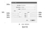
新專案對話框圖3C展示根據一項所圖解說明實施方案由圖2之基於處理器之系統呈現之圖像使用者介面之一新專案對話框314。New Project Dialog Figure 3C shows a
新專案對話框314提示一使用者形成一新專案。新專案對話框314提供一「專案名稱」欄位314a以鍵入將變成該專案之目錄名稱的一名稱。新專案對話框314提供一「專案路徑」欄位314b以鍵入將在其中形成專案之一目錄。新專案對話框314提供一「URDF路徑」欄位314c以鍵入至待使用之一URDF或*.xacro檔案之一路徑。新專案對話框314提供一「ROS封裝路徑」欄位314d以在URDF使用此欄位之情形下鍵入一「package://」首碼來規定檔案路徑。此可用於規定至彼等頂層目錄之一路徑。新專案對話框314提供分別對應於專案路徑欄位314b、URDF路徑欄位314c及ROS封裝路徑314d之一組使用者可選擇瀏覽圖符314e、314f、314g,對其等之選擇允許使用者瀏覽適當輸入以選擇各別欄位。The new
新專案對話框314提供一「運動鏈開始」欄位314h以在運動鏈將開始之情形中規定來自URDF之一機器人連結。所規定連結不應具有任何可移動父關節。特定而言,運動鏈開始欄位提供一可捲動連結清單以自其選擇。新專案對話框314提供一「運動鏈結束」欄位314i以在運動鏈將結束之情形中規定來自URDF之一機器人連結。此連結應係運動鏈開始之一子項,且不具有作為子項之可移動關節。為使碰撞檢查成為可能,對於每一姿勢,必須完全知曉機器人中之每一可移動關節。The
檔案選單返回至圖3A及圖3B,檔案下拉選單302a可包含一使用者可選擇「載入專案」選單項,對其之選擇致使系統或應用載入一現有專案。檔案下拉選單302a可包含一使用者可選擇「保存專案」欄位選單項,對其之選擇致使系統或應用將一當前專案保存在一相同位置中。選擇將刪除針對專案而存在之任何自動保存之檔案。檔案下拉選單302a可包含一使用者可選擇「專案另存為」選單項,對其之選擇致使系統或應用將當前專案作為一新例項複製至一新位置。檔案下拉選單302a可包含一使用者可選擇「載入場景快照」選單項,對其之選擇致使系統或應用將自一rtr-api形成之一快照載入至呈現窗口304中以供查看。檔案下拉選單302a可包含一使用者可選擇「匯出組態」選單項,對其之選擇致使系統或應用匯出作用工作空間之全部有效關節組態。檔案下拉選單302a可包含一使用者可選擇「匯出邊緣」選單項,對其之選擇致使系統或應用匯出作用工作空間之全部有效邊緣。檔案下拉選單302a可包含一使用者可選擇「匯出姿勢」選單項,對其之選擇致使系統或應用匯出作用工作空間之全部有效姿勢。File Menu Returning to Figure 3A and Figure 3B, the file drop-
繼續參考圖3A及圖3B,「編輯」下拉選單302b允許一使用者選擇一「設定」選單。「設定」選單提供用於專案設定及工作空間設定之使用者可選擇選項。Continuing to refer to FIGS. 3A and 3B, the "Edit" drop-
專案「設定」允許使用者設定(例如,雙態切換)自動姿勢驗證。自動姿勢驗證設定判定一路線圖區域或中樞之任一改變是否將導致系統或應用自動重新計算姿勢。此程序在後臺中發生。若與極大動作規劃圖像或路線圖一起工作,則一使用者可期望停用自動姿勢驗證。The project "Settings" allows users to set (for example, two-state switching) automatic posture verification. The automatic posture verification setting determines whether any change in a route map area or hub will cause the system or application to automatically recalculate the posture. This process happens in the background. If working with a maximal motion planning image or a road map, a user may wish to disable automatic posture verification.
專案設定允許使用者設定(例如,雙態切換)原始姿勢是否隨區域旋轉。原始姿勢以區域設定旋轉判定旋轉一路線圖區域將如何操作。若原始姿勢以區域設定旋轉經停用,則一路線圖區域中之姿勢之定向將相對於世界保持固定。若原始姿勢以區域設定旋轉經啟用,則彼等定向將作為一整體與整個區域一起旋轉。The project setting allows the user to set (for example, two-state switching) whether the original posture rotates with the area. The original posture uses the area setting rotation to determine how to rotate a route map area. If the original posture rotation is disabled in the area setting, the orientation of the posture in a route map area will remain fixed relative to the world. If the original pose is enabled with region setting rotation, their orientations will be rotated together with the entire region as a whole.
工作空間設定允許使用者設定運動鏈。運動鏈設定設定系統用於碰撞檢查姿勢計算之運動鏈。一旦設定,此鏈便不可編輯。為改變運動鏈設定,最終使用者形成一新專案。工作空間設定允許最終使用者組態URDF中哪些連結進行彼此碰撞檢查。因此,歸因於,最終使用者可選擇停用由於實體位置或關節限制約束將永不碰撞之連結之間的碰撞檢查,從而有利地減少處理時間。可經由一碰撞矩陣來實施組態。The workspace setting allows the user to set the kinematic chain. The kinematic chain setting system is used for the kinematic chain of collision check posture calculation. Once set, this chain cannot be edited. In order to change the kinematic chain settings, the end user forms a new project. Workspace settings allow end users to configure which links in the URDF are checked for collisions with each other. Therefore, due to the fact that the end user can choose to deactivate the collision check between the links that will never collide due to the physical position or joint restriction constraints, thereby advantageously reducing the processing time. The configuration can be implemented via a collision matrix.
一最終使用者可致使系統或應用(舉例而言)經由一「匯入SRDF」使用者介面元素自一SRDF檔案匯出一碰撞矩陣。An end user can cause the system or application (for example) to export a collision matrix from an SRDF file via an "import SRDF" user interface element.
一最終使用者可致使系統或應用定義動作規劃圖像或路線圖如何經由一「內插類型矩陣」使用者介面元素彼此連接及/或連接至中樞。可用選項可包含:關節、笛卡耳或不連接。An end user can cause the system or application to define how the action plan image or roadmap is connected to each other and/or to the hub via an "interpolation type matrix" user interface element. Available options can include: joints, cartesian ears, or no connection.
一個或多個欄標允許一最終使用者形成可附接至URDF中之任何連結之任意位置之各種部位。系統或應用在執行碰撞檢查時使用此等部位。部位可採取各種形式中之任一者,舉例而言一方塊、球體或圓柱體,且可儲存為一部位庫。最終使用者可規定或調整部位之大小。One or more fields allow an end user to form various parts that can be attached to any link in the URDF. The system or application uses these parts when performing collision checks. The part can take any of various forms, for example, a block, sphere, or cylinder, and can be stored as a part library. The end user can specify or adjust the size of the part.
相機/視點選單相機或視點選單302c允許一使用者切換視圖,舉例而言,在一透視圖模式與一正視視圖模式之間切換。另一選擇係,可選擇(例如,點選)在三維視圖中呈現之一組軸之一中心處之一立方體(位於右上角)以在相機設定之間進行雙態切換。Camera/Viewpoint Menu The camera or
幫助選單幫助下拉選單302d之選擇致使呈現具有一使用者可自其選擇之各種幫助選單項之一幫助選單。Help Menu The selection of the help drop-
呈現窗口呈現窗口304提供所載入機器人工作單元之一個三維視圖。一最終使用者可在呈現窗口304內進行移動瀏覽、環繞移動及縮放。中樞、路線圖區域、姿勢、邊緣及體素區域全部在呈現窗口304中視覺化。選擇(例如,點選)一物件(例如,機器人)將使彼物件成為所選擇物件。The presentation window The
存在使用可在呈現窗口304中獲得之工具來操縱機器人模型305及任何路線圖區域兩者之數種不同方式。There are several different ways of using tools available in the
呈現窗口304包含一「FK面板」使用者可選擇圖符304a,對其之選擇致使一FK面板之呈現。FK面板允許一最終使用者規定關節角度作為輸入,且系統或應用將判定機器人在三維空間中之對應位置且呈現機器人之對應三維位置。The
呈現窗口304包含一「IK面板」使用者可選擇圖符304b,對其之選擇致使一IK面板之呈現。IK面板允許一最終使用者規定三維中之機器人之至少一部分(例如,末端執行器)之一位置,且該系統或應用將判定機器人之對應關節角度以將機器人之該部分定位在三維空間中並呈現對應關節角度。The
「FK面板」及「IK面板」亦在C空間與三維空間或真實世界空間之間簡單地平移。「FK面板」及「IK面板」亦允許一最終使用者對末端執行器之一平移及/或旋轉進行精細調整。每一調整之增量可改變。可在「世界」參考座標系中或在任何經定義路線圖區域之一參考座標系中查看當前位置。"FK panel" and "IK panel" also simply translate between C space and three-dimensional space or real world space. "FK Panel" and "IK Panel" also allow an end user to fine-tune the translation and/or rotation of one of the end effectors. The increment of each adjustment can be changed. The current position can be viewed in the "world" reference coordinate system or in one of the defined route map areas.
呈現窗口304包含平移介面控件304c。取決於選擇哪個項,系統或應用致使平移介面控件304c顯現在機器人之末端執行器處或一路線圖區域或一體素區域之原點處。平移介面控件304c允許一最終使用者(舉例而言)藉由定位一指標或標(例如,滑鼠懸停)且在對應軸上進行選擇(例如,點選)來在三維(x、y或z軸)中拖拉所選擇項。可藉由選擇(例如,點選)一使用者可選擇圖符(例如,「T」按鈕)來啟用/停用平移介面控件304c。The
呈現窗口304包含一旋轉介面控件304d。取決於選擇哪個項,系統或應用致使旋轉介面控件304d顯現在機器人之末端執行器處或一路線圖區域之原點處。旋轉介面控件304d允許一最終使用者藉由選擇(例如,點選)且在選擇時拖拉對應軸而使所選擇項圍繞三個軸(x、y或z軸)旋轉。可藉由選擇(例如,點選)一使用者可選擇圖符(例如,「R」按鈕)來啟用/停用旋轉介面控件304d。The
呈現窗口304包含一按比例調整介面控件304e。該系統或應用致使按比例調整介面控件304e出現在一路線圖或體素區域之原點處。按比例調整介面控件304e允許一最終使用者改變三維(x、y或z)中之所選擇物件之尺寸。若按比例調整一路線圖區域,則系統或應用將基於彼特定區域之一密度設定而自動增加及/或減少該區域內部之姿勢數目。The
呈現窗口304包含關節拖曳模式使用者可選擇圖符304f。當關節拖曳模式係作用中時,平移、旋轉及按比例調整介面控件304c、304d、304e被停用,且最終使用者可懸停(例如,滑鼠懸停)在機器人表示上之一可移動連結上方。當選擇連結時,系統或應用將在視覺上指示此連結(例如,突出顯示連結),且將導致表示可能關節行進之一視覺指示(例如,螺旋線)之呈現。一最終使用者然後可相對於該視覺指示移動連結(例如,球)之一表示,舉例而言,在螺旋線上上下移動一球以控制關節之位置。系統或應用根據輸入更新位置。The
呈現窗口304包含一組三維控制項304g。最終使用者可操縱三維控制項304g以致使該系統或應用調整呈現窗口304中所呈現之一個三維視圖。舉例而言,最終使用者可藉由(舉例而言)在一滑鼠或其他指標裝置上固持住一按鈕來移動瀏覽所表示場景。最終使用者可藉由在一滑鼠或其他指標裝置上固持住另一按鈕來旋轉該視圖。最終使用者可舉例而言經由一滑鼠或其他指標裝置上之一捲動輪來控制縮放。呈現窗口304可舉例而言包含一個三維控制圖符304g (例如,圖解說明於呈現窗口304之右上方處),最終使用者可藉助一指標對其進行操縱,且其允許最終使用者快速移動至一特定經軸對準之視圖,以及在正交與透視模式之間切換。The
專案面板專案面板306列出當前工作空間中之全部物件及專案。選擇(例如,點選)一項將使該項成為所選擇項,從而提供更多資訊。Project Panel The
專案面板306包含一工作空間區段306a,其允許最終使用者查看全部可用工作空間以及形成新工作空間。為形成一新工作空間,最終使用者在「工作空間名稱」文字欄位中打字輸入一名稱且選擇「添加」使用者可選擇圖符306b。最終使用者亦可使用「作用工作空間」下拉選單306c來選擇哪個工作空間係當前工作空間。注意,形成一新工作空間不自動使新工作空間成為作用工作空間。當前作用工作空間顯示在呈現窗口304中,且專案面板306上所列出之全部區域及碰撞部位係基於作用工作空間。一最終使用者可藉由選擇(例如,點選)待克隆之工作空間來複製一現有工作空間,然後在專案面板306上選擇「複製」使用者可選擇圖符308a。The
專案面板306包含一個體素區域區段306d。體素區域區段306d具有三個使用者可選擇圖符(例如,按鈕),每一者具有一不同功能。一「目標」使用者可選擇圖符306e使最終使用者選擇體素區域,因此檢驗器面板308展示關於所選擇體素區域之細節,以及在呈現窗口304中顯示變換或按比例調整控制。「眼睛」使用者可選擇圖符306f使最終使用者在呈現窗口304上雙態切換體素區域之可見性。「體素」使用者可選擇圖符306g使最終使用者在呈現窗口304上雙態切換體素之可見性。The
專案面板306包含路線圖區域區段306h。路線圖區域區段306h對最終使用者展示作用工作空間中之全部可用路線圖區域。在一區域上進行選擇(例如,點選)將在檢驗器面板308上且在呈現窗口304中選擇彼區域,因此可旋轉、按比例調整或變換所選擇區域。選擇(例如,點選)一「添加」使用者可選擇圖符306i將致使系統或應用在機器人之末端執行器之一當前位置處形成一新路線圖區域,且顯示一選單以允許最終使用者添加新原始姿勢。選擇(例如,點選)一「匯入」使用者可選擇圖符306j將致使系統或應用提示最終使用者選擇用於匯入之檔案。所匯入路線圖區域可經變換及旋轉,但不按比例調整。選擇(例如,點選)一「複製」使用者可選擇圖符306k將克隆所選擇路線圖區域。The
專案面板306包含一中樞區段306l。中樞區段306l呈現已在專案中形成的全部可用中樞。一最終使用者可選擇(例如,點選)一項目且在檢驗器面板308中選擇該中樞。在一項上進行雙選擇(例如,雙點選)可致使系統或應用將機器人模型移動至由所選擇中樞識別之一姿勢。舉例而言,可藉由在一名稱欄位306m中鍵入一名稱且選擇(例如,點選)一「添加」使用者可選擇圖符306n來添加一新中樞。作為回應,系統或應用將在機器人模型之末端執行器之一當前位置處形成一新中樞。The
專案面板306包含一碰撞部位區段306o。碰撞部位區段306o呈現當前附接至一機器人模型或操作環境之全部部位。在該等部位中之一者上進行選擇(例如,點選)致使系統或應用呈現用於所選擇項之檢驗器面板308。最終使用者可藉由選擇(例如,點選)一「添加」使用者可選擇圖符306p來附接一新部位,對其之選擇致使系統或應用提示最終使用者命名該連接、自部位庫選擇待附接之一部位、識別將該部位附接至哪個連結且規定該部位應如何連接至一父連結之一偏移。若部位庫中不存在部位,則可經由設定面板來添加一部位。附接一部位亦將致使系統或應用修改當前工作空間之碰撞矩陣。藉由預設,將不針對父連結對碰撞部位進行碰撞檢查,但將對URDF中之所有其他連結進行碰撞檢查。若一部位附接至不在運動鏈中之一連結,則系統或應用仍會將其視為一碰撞。若附接一部位使無法解釋之姿勢無效,則最終使用者可檢查以確保碰撞矩陣對於新的經附接部位係正確的。The
專案面板306包含一姿勢驗證狀態區段(例如,專案面板之底部處之藍色條) 306q。姿勢驗證狀態區段306q提供已完成之一姿勢驗證百分比之一指示。每當您形成或修改一區域或中樞時,系統或應用便執行姿勢驗證。此系統或應用在後臺執行此程序,且當完成時,全部姿勢將識別為有效或無效。系統或應用可使用一第一視覺特性(例如,顏色為綠色)來視覺地表示有效姿勢,使用一第二視覺特性(例如,顏色為紅色)來視覺地表示無效姿勢。若在已執行驗證的同時修改需要姿勢產生之一項,則系統或應用將重新開始驗證程序。通常,姿勢驗證將自動執行,但最終使用者可舉例而言針對大動作規劃圖像或路線圖經由設定面板來停用此特徵,。若停用自動姿勢驗證,則舉例而言將在進度列下方呈現一「驗證」使用者可選擇圖符(例如,綠色按鈕)。The
專案面板306包含產生邊緣使用者可選擇圖符306r。一旦已設置圖像或路線圖且已完成姿勢驗證,最終使用者便可選擇(例如,點選)「產生邊緣」使用者可選擇圖符306r。選擇「產生邊緣」使用者可選擇圖符306r致使系統或應用啟動將一當前作用工作空間中之全部姿勢連接至一個經連接路線圖中之一程序。在此程序期間,系統或應用將使用每一路線圖區域之設定及內插矩陣來判定將哪些姿勢彼此連接。系統或應用然後對每一可能連接進行碰撞檢查以判定該連接是否有效。在完成此程序之後,最終使用者可希望將邊緣視覺化。The
專案面板306包含一「連接可見」使用者可選擇圖符(例如,核取方塊、選項按鈕)。系統或應用將使用一第一視覺特性(例如,藍色)來呈現有效邊緣,同時使用一第二視覺特性(例如,紅色)來呈現無效邊緣。取決於當前工作空間之複雜性,系統或應用可花費一些時間來判定有效邊緣且對此進行再現。The
一旦邊緣係滿足的,便可針對當前作用工作空間產生一佔用檔案。佔用檔案可由MPA採用,舉例而言在運行時間操作期間。專案面板306包含一產生佔用使用者可選擇圖符306s (例如,核取方塊、選項按鈕)。對產生佔用使用者可選擇圖符306t之選擇(例如,點選)致使系統或應用產生當前作用工作空間之佔用檔案。在系統或應用中,可提示最終使用者選擇佔用檔案之一檔案名稱。在鍵入一名稱之後,最終使用者可旋即選擇(例如,點選)一「保存」使用者可選擇圖符。對「保存」使用者可選擇圖符之選擇致使系統或應用開始該產生程序,取決於路線圖之複雜性,此可花費一長時間。注意,可針對使用中之每一工作空間產生一各別佔用檔案。Once the marginal system is satisfied, an occupancy file can be generated for the current working space. Occupancy files can be used by MPA, for example during runtime operations. The
檢驗面板檢驗器面板308呈現關於當前所選擇物件之資訊。檢驗器面板308可係內容脈絡敏感的,且所顯示之資訊將取決於選擇何種類型之物件而不同。舉例而言,檢驗器面板308可在如經由一座標系選擇使用者介面(例如,下拉選單或清單) 308b所選擇的真實世界參考座標系或某一其他參考座標系中呈現模型化機器人之一末端執行器之一位置及定向。檢驗器面板308亦可展示系統或應用基於碰撞分析而判定為處於碰撞中之任何連結之一清單。Inspection Panel The
視圖控制面板視圖控制面板310包含控制在呈現窗口304中顯示哪些物件之介面控件。視圖控制面板310允許最終使用者選擇在顯示體素或查看路徑時將哪個姿勢或邊緣視覺化。View control panel The
一「中樞可見」使用者介面元素(例如,核取方塊) 308c允許最終使用者選擇(例如,若經檢查)以使在專案中已形成之中樞顯示在呈現窗口304中。A "hub visible" user interface element (e.g., check box) 308c allows the end user to select (e.g., if checked) to display the hub that has been formed in the project in the
一「姿勢可見」使用者介面元素(例如,核取方塊) 308d允許最終使用者選擇(例如,若經檢查)使已針對作用工作空間產生之姿勢顯示在呈現窗口304中。A "posture visible" user interface element (e.g., check box) 308d allows the end user to choose (e.g., if checked) to display the posture that has been generated for the active workspace in the
一「連接可見」使用者介面元素(例如,核取方塊) 308e允許最終使用者選擇(例如,若經檢查)使已針對作用工作空間產生之邊緣連接顯示在呈現窗口304中。A "connection visible" user interface element (for example, a check box) 308e allows the end user to choose (for example, if checked) to display in the
一「路徑可見」使用者介面元素(例如,核取方塊) 308f允許最終使用者在若顯示模式係邊緣模式的情況下選擇(例如,若經檢查)使臂針對當前指標將行進通過之路徑顯示在呈現窗口304中。若「路徑可見」使用者介面元素未經檢查且顯示模式係處於邊緣模式中,則機器人臂將沿著所選擇邊緣來回移動。A "path visible" user interface element (for example, check box) 308f allows the end user to select (for example, if checked) if the display mode is edge mode, the arm will display the path through which the current pointer will travel In the
一「快拍體素區域」使用者介面元素(例如,雙態切換開關) 308g允許最終使用者選擇使系統或應用計算並更新體素區域之位置及尺寸,因此所得體素區域圍封動作規劃圖像或路線圖中機器人在每一所產生邊緣上之全部位置。A "snap voxel area" user interface element (for example, a toggle switch) 308g allows the end user to choose to have the system or application calculate and update the position and size of the voxel area, so the resulting voxel area encloses the action plan All positions of the robot on each generated edge in the image or road map.
一「顯示模式」使用者介面元素(例如,下拉選單) 308h允許最終使用者在一姿勢模式與一邊緣模式之間進行選擇以便呈現在呈現窗口304中。當處於「姿勢模式」中時,一「指標」欄位之一值之一改變將致使系統或應用使機械臂跳至所指示位置。當處於邊緣模式中時,指標欄位之一值之一改變將致使系統或應用將機器人之臂沿著所選擇邊緣來回移動,或者若選擇「路徑可見」,則系統或應用將致使呈現末端執行器針對彼邊緣所採取之一路徑。A "display mode" user interface element (for example, a drop-down menu) 308h allows the end user to choose between a gesture mode and an edge mode for presentation in the
一「指標」使用者介面元素(例如,欄位) 308i允許最終使用者選擇哪個姿勢或邊緣係作用的且如何顯示彼姿勢或邊緣。當產生姿勢或邊緣時,其等以一大陣列儲存在系統中。A "pointer" user interface element (for example, a field) 308i allows the end user to select which posture or edge is active and how to display that posture or edge. When a gesture or edge is generated, it is stored in the system in a large array.
一「快照視圖」使用者介面元素(例如,下拉選單) 308j允許最終使用者在一快照已自「檔案」選單載入至系統的情況下選擇顯示何種類型之資料。A "snapshot view" user interface element (for example, a drop-down menu) 308j allows the end user to choose what type of data to display when a snapshot has been loaded into the system from the "file" menu.
控制台面板控制台面板312顯示來自系統或應用之全部日誌輸出。控制台面板312顯示來自系統之訊息、警告及錯誤。Console Panel The
圖3D展示根據一項所圖解說明實施方案由圖2之基於處理器之系統呈現的圖像使用者介面之一「碰撞部位附接」對話框320。FIG. 3D shows a "collision site attachment"
「碰撞部位附接」對話框320包含用以規定一附接名稱之一「附接名稱」欄位320a,用以選擇一附接部位之一附接部位下拉清單以及用以選擇一父連結之一父連結下拉清單。「碰撞部位附接」對話框320亦包含用於鍵入經由x、y、z軸座標320b、320c、320d之一個三維姿勢之欄位以及圍繞x、y、z軸320e、320f、320g之定向角度。使用者可選擇圖符允許以最終使用者接受或取消該附接。The "Collision Part Attach"
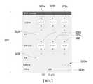
圖3E展示根據一項所圖解說明實施方案由圖2之基於處理器之系統呈現的圖像使用者介面之一IK面板322。IK面板322可用於規定正模型化之機器人之一末端執行器之一姿勢。FIG. 3E shows an
IK面板322包含顯示經由x、y、z軸座標之一個三維姿勢及圍繞x、y、z軸之定向角度之位置欄位322a、322b、322c及旋轉欄位322d、322e、322f。IK面板320包含用於每一位置及旋轉欄位之一對使用者可選擇位置及旋轉調整圖符(例如,向上箭頭、向下箭頭) 322g、322h、322i、322j,對其之選擇調整姿勢。IK面板320包含位置及旋轉增量欄位322k、322l,以設定當選擇位置調整圖符及/或旋轉調整圖符時分別調整位置及旋轉之一增量大小。IK面板322包含一組貼齊至軸使用者可選擇元素(例如,雙態切換開關) 322m,對其之選擇致使系統或應用將一座標貼齊至一各別軸。IK面板322包含參考座標系下拉清單322n,以選擇其中表達座標之一參考座標系(例如,真實世界)。The
如先前所述,檢驗面板308可係內容脈絡敏感的,且基於當前選擇之何種類型之項而顯示資訊。As previously described, the
圖3F展示根據一項所圖解說明實施方案呈由圖2之基於處理器之系統呈現的圖像使用者介面之一機器人檢驗器面板308-1之形式的檢驗器面板308。3F shows a
機器人檢驗器面板308-1展示關於機器人在作用工作空間中之狀態之資訊。此等包含諸如來自urdf之一名稱308-1a (哪個網目模式308-1b正用於繪製機器人(碰撞或視覺))之事項及末端執行器之一姿勢,舉例而言末端執行器在x、y、z軸308-1c、308-1d、308-1e中之一位置及圍繞x、y、z軸308-1f、308-1g、308-1h之一定向(包含在其中查看座標之座標系)。一「參考座標系選擇」下拉清單308-1i允許一使用者選擇一參考座標系。其亦包含一表308-1j,該表列出當前彼此在碰撞中之全部機器人連結。此資訊可幫助您快速診斷並校正彼當前工作空間之碰撞矩陣中之任何錯誤。可藉由在三維面板304中點選機器人上之任何可移動連結而使機器人檢驗器面板308-1可見。The robot checker panel 308-1 displays information about the state of the robot in the working space. These include things such as the name 308-1a from the urdf (which mesh mode 308-1b is being used to draw the robot (collision or vision)) and a posture of the end effector. For example, the end effector is in x, y , Z axis 308-1c, 308-1d, 308-1e and one of the x, y, z axis 308-1f, 308-1g, 308-1h orientation (including the coordinate system in which the coordinates are viewed) . A "reference coordinate system selection" drop-down list 308-1i allows a user to select a reference coordinate system. It also contains a table 308-1j, which lists all the robot connections that are currently colliding with each other. This information can help you quickly diagnose and correct any errors in the collision matrix of your current workspace. The robot checker panel 308-1 can be made visible by clicking any movable link on the robot in the three-
圖3G展示根據一項所圖解說明實施方案呈由圖2之基於處理器之系統呈現的圖像使用者介面之一「工作空間檢驗器」面板308-2之形式之檢驗器面板308。3G shows a
可藉由點選您將可能檢驗專案面板之工作空間而使「工作空間檢驗器」面板308-2可見。檢驗器面板308-2包含:一「狀態」欄位308-2a,其識別一當前狀態;一「複製」使用者可選擇圖符(例如,按鈕) 308-2b,對其之選擇致使系統或應用複製或克隆該工作空間。檢驗器面板308-2包含用於IK求解之運動鏈之一開始連結308-2c及結束連結308-2d之指示。檢驗器面板308-2亦包含統計資料,包含若干個有效及無效姿勢308-2e以及有效及無效邊緣308-2f之指示。檢驗器面板308-2包含一「組態」使用者可選擇圖符308-2g、「邊緣」使用者可選擇圖符308-2h及「姿勢」使用者可選擇圖符308-2i,其等分別提供匯出所產生關節組態、邊緣及姿勢之能力。You can make the "Workspace Inspector" panel 308-2 visible by clicking the workspace where you will be able to inspect the project panel. The checker panel 308-2 includes: a "status" field 308-2a, which identifies a current state; a "copy" user can select an icon (for example, a button) 308-2b, the selection of which causes the system or The application copies or clones the workspace. The checker panel 308-2 contains instructions for the start link 308-2c and the end link 308-2d of one of the kinematic chains for IK solving. The checker panel 308-2 also contains statistical data, including indications of a number of valid and invalid postures 308-2e and valid and invalid edges 308-2f. The checker panel 308-2 includes a "configuration" user-selectable icon 308-2g, "edge" user-selectable icon 308-2h, and "posture" user-selectable icon 308-2i, etc. Provide the ability to export the generated joint configuration, edge and posture respectively.
可藉由編輯工作空間檢驗器面板308中之一名稱欄位(例如,頂部欄位)來重新命名工作空間。可藉由點選選擇(例如,點選)緊挨名稱欄位之「x」來刪除該工作空間。The workspace can be renamed by editing one of the name fields (for example, the top field) in the
一個「體素區域檢驗器」面板(未展示)呈現體素區域之當前座標(x、y、z)以及其當前尺寸。可藉由選擇(例如,點選)專案面板上之一「目標」圖符而使「體素區域檢驗器」面板可見。A "Voxel Area Checker" panel (not shown) displays the current coordinates (x, y, z) of the voxel area and its current size. The "Voxel Area Checker" panel can be made visible by selecting (for example, clicking) one of the "Target" icons on the project panel.
一「路線圖區域檢驗器」面板(未展示)呈現關於一當前所選擇區域之資訊且允許一最終使用者做出姿勢如何在區域中產生且彼此連接之改變。A "Roadmap Area Checker" panel (not shown) presents information about a currently selected area and allows an end user to make changes to how gestures are generated in the area and connected to each other.
當按比例調整一路線圖區域時,姿勢間距值判定每一姿勢之間的一間距。舉例而言,若使路線圖區域變得更大,則將以由一既定姿勢間距值規定之間隔添加更多姿勢。When adjusting a route map area proportionally, the posture interval value determines a gap between each posture. For example, if the route map area is made larger, more gestures will be added at an interval specified by a predetermined gesture spacing value.
「連接密度」值可規定或控制由系統或應用產生之邊緣之數目。一內部值控制在當前所選擇區域內部之全部姿勢之間產生多少邊緣。假定將區域之間的連接設定為根據內插矩陣而連接,一外部值控制在當前所選擇區域與全部其他區域之間產生多少邊緣。The "connection density" value can specify or control the number of edges generated by the system or application. An internal value controls how many edges are generated between all the postures inside the currently selected area. Assuming that the connection between the regions is set to be connected according to the interpolation matrix, an external value controls how many edges are generated between the currently selected region and all other regions.
一「內部動作類型」值判定是否將使用關節或笛卡耳內插類型來形成一所選擇路線圖區域中之每一姿勢之間的邊緣。A value of "Internal Action Type" determines whether joint or Cartesian interpolation type will be used to form the edge between each posture in a selected route map area.
一「中樞檢驗器」面板(未展示)展示世界座標系中之中樞之當前位置(x、y、z、側滾、縱傾、側傾)。轉至按鈕(Go To button)將機器人模型移動至彼中樞,且點選「更新姿勢」按鈕將致使中樞之位置及關節組態變成當前機器人模型之位置及組態。A "Central Detector" panel (not shown) displays the current position (x, y, z, roll, pitch, and tilt) of the center of the world coordinate system. The Go To button will move the robot model to that center, and clicking the "Update Posture" button will cause the position and joint configuration of the center to become the position and configuration of the current robot model.
一「碰撞部位檢驗器」面板(未展示)展示碰撞部位之名稱、其當前父代及自其父代之安裝偏移以及其尺寸。可藉由點選緊挨名稱欄位之「x」按鈕來刪除該部位。A "Collision Part Inspector" panel (not shown) displays the name of the collision part, its current parent and the installation offset from its parent, and its size. This part can be deleted by clicking the "x" button next to the name field.
一檢驗器亦使最終使用者藉由將新數目鍵入至對應欄位來查看及編輯一區域之一位置及大小,以及管理「原始姿勢」。A validator also allows the end user to view and edit the position and size of an area by typing a new number into the corresponding field, and manage the "original posture".
圖3H展示根據一項所圖解說明實施方案由圖2之基於處理器之系統呈現的圖像使用者介面之一「設定原始姿勢」對話框330。FIG. 3H shows a "Set Original Pose"
原始姿勢係闡述如何對一既定路線圖區域中之全部其他姿勢進行播種之該組姿勢。選擇(例如,點選)「管理原始姿勢」使用者可選擇圖符(例如,按鈕)致使系統或應用將機器人模型鎖定為末端執行器座標保持鎖定但可透過旋轉控制介面控件及/或IK窗口圍繞彼點旋轉之一模式。The original posture is the group of postures that explain how to seed all other postures in a given route map area. Select (for example, click) "Manage Original Posture". The user can select the icon (for example, button) to cause the system or application to lock the robot model as the end effector. The coordinates remain locked but can be controlled by rotating the interface controls and/or the IK window A mode of rotation around that point.
「設定原始姿勢」對話框330包含一「區域名稱」欄位330a以鍵入或顯示一區域名稱。「設定原始姿勢」對話框330包含一「轉至」使用者可選擇圖符330b,對其之選擇致使系統或應用將該項移動至所選擇姿勢。可接著藉由選擇(例如,點選)一「添加當前姿勢」使用者可選擇圖符330c來添加至路線圖區域之一新原始姿勢。對於添加至路線圖區域之每一原始姿勢,系統或應用將形成匹配區域之密度及間距參數之一組姿勢,以對應原始姿勢之定向進行播種。若啟用「姿勢可見」且添加多個原始姿勢,則定向差異應顯而易見。「設定原始姿勢」對話框330包含一「更新」使用者可選擇圖符330d,對其之選擇致使系統或應用更新原始姿勢。「設定原始姿勢」對話框330包含一「刪除」使用者可選擇圖符330e,對其之選擇致使系統或應用刪除一原始姿勢。The "Set Original Pose"
圖3I展示根據一項所圖解說明實施方案在一第三時間處由圖2之基於處理器之系統呈現的圖像使用者介面之一呈現窗口304,其展示一實例性機器人340、具有多個原始姿勢344之路線圖區域342。FIG. 3I shows a
圖3J展示根據一項所圖解說明實施方案在一第四時間處由圖2之基於處理器之系統呈現的圖像使用者介面之一呈現窗口304,其展示一實例性機器人340、工作空間346及當選擇一路徑可見選項時一當前邊緣之路徑348。FIG. 3J shows a
圖4A係根據一項所圖解說明之實施例圖1之機器人102之一實例動作規劃圖像400,包含已判定對應轉變將導致機器人102與環境100中之一或多個障礙物之間的一碰撞之規劃圖像400之邊緣。圖4B係根據一項所圖解說明之實施例一實例動作規劃圖像400,其中已判定對應轉變將導致機器人102與環境100中之一或多個障礙物之間的一碰撞之規劃圖像400之邊緣已移除。規劃圖像400之每一節點表示機器人102之一狀態且規劃圖像400之每一邊緣表示機器人102自一個狀態至另一狀態之一轉變。舉例而言,邊緣410a表示由節點408a表示之機器人102之一狀態與由節點408b表示之機器人102之一狀態之間的一轉變。邊緣410i表示由節點408c表示之機器人102之一狀態與由節點408d表示之機器人102之一狀態之間的一轉變。FIG. 4A is an example
機器人102之規劃圖像400之每一邊緣具有某些數目之體素(或方塊),其等對應於由機器人102在進行由彼邊緣表示之規劃圖像400中自一個狀態至另一狀態之轉變時掃掠之3D空間中之體積。此資訊可作為規劃圖像邊緣資訊儲存在晶片外規劃圖像邊緣資訊記憶體284中,使得系統200可調出不同規劃圖像以適應機器人102之改變尺寸。使用在運行時間處自感測器282接收之表示當前環境之資訊,系統200判定當前佔用哪些體素(或方塊),且系統200判定不使用將與任何當前所佔用體素(或方塊)碰撞之任何動作。Each edge of the
在某些實施例中,系統藉由將在運行時間處自感測器282接收且儲存在單晶片環境記憶體294中之表示當前環境(及其中之障礙物)之資訊與儲存在規劃圖像邊緣資訊記憶體284中之規劃圖像邊緣資訊進行比較來判定不使用將與所佔用體素(或方塊)碰撞之任何動作。基於此比較,系統200判定哪些規劃圖像邊緣表示將導致機器人102與環境100中之一或多個障礙物之間的一碰撞之轉變(及因此其對應動作)。作為一實例,圖4A展示邊緣410b、410c、410d、410e、410f、410g、410h、410i、410j、410k及410l已經判定以表示將導致機器人102與環境100中之一或多個障礙物之間的一碰撞之轉變(及因此其對應動作)。In some embodiments, the system stores the information representing the current environment (and obstacles in it) received from the
舉例而言,為使機器人102達成自由節點408a表示之一狀態移動至由節點408d表示之一狀態之一目標,機器人102將必須避免由邊緣410b、410c、410d、410e、410f、410g、410h、410i、410j、410k及410l表示之轉變,該等邊緣已經判定以表示將導致機器人102與環境100中之一或多個障礙物之間的一碰撞之轉變。因此,圖4B展示具有經移除之此等邊緣之規劃圖像及由系統200識別之規劃圖像400中之一潛在路徑416,其中機器人102可依循以達成自由節點408a表示之狀態移動至由節點408d表示之狀態而不與環境100中之一或多個障礙物碰撞之一目標。For example, in order for the
圖5展示根據一項所圖解說明之實施例在一基於處理器之系統200中操作之一方法500。在一基於處理器之系統200中操作之方法500開始於502處,舉例而言回應於一系統之一呼叫或調用或接通電源。Figure 5 shows a
在504處,經由一基於處理器之系統或經由一基於處理器之系統執行之應用來呈現一使用者介面。At 504, a user interface is presented via a processor-based system or an application executed via a processor-based system.
在506處,經由基於處理器之系統或應用接收或規定一機器人模型。At 506, a robot model is received or specified via the processor-based system or application.
在508處,經由基於處理器之系統或應用接收或規定一離散化操作環境。At 508, a discretized operating environment is received or specified via the processor-based system or application.
在510處,經由經由基於處理器之系統或應用呈現之使用者介面來呈現離散化操作環境中之機器人模型之一表示。At 510, a representation of the robot model in the discretized operating environment is presented via a user interface presented via a processor-based system or application.
在512處,基於處理器之系統或應用經由使用者介面接收規定一或多個種子姿勢之輸入,舉例而言,作為輸入。種子姿勢可手動鍵入,或者提供為一檔案或至一檔案之連結。At 512, the processor-based system or application receives input specifying one or more seed gestures via the user interface, for example, as input. The seed pose can be entered manually or provided as a file or a link to a file.
視情況,在514處,基於處理器之系統或應用自主地執行自主地產生之種子姿勢之運動檢查及/或碰撞檢查。舉例而言,基於處理器之系統或應用自主地判定種子姿勢或種子姿勢之間的轉變(例如,邊緣)是否違反被模型化之機器人之任何運動約束。亦舉例而言,基於處理器之系統或應用自主地判定與物件(例如,環境中之已知靜態物件)之任何碰撞是否將由種子姿勢或種子姿勢之間的轉變引起。Optionally, at 514, the processor-based system or application autonomously executes the motion check and/or collision check of the autonomously generated seed pose. For example, a processor-based system or application autonomously determines whether seed poses or transitions between seed poses (eg, edges) violate any motion constraints of the modeled robot. For example, a processor-based system or application autonomously determines whether any collision with an object (for example, a known static object in the environment) will be caused by a seed pose or a transition between seed poses.
在516處,若不違反運動約束且未偵測到碰撞,則基於處理器之系統或應用將一或多個種子姿勢及/或任何相關聯邊緣添加至動作規劃圖像、路線圖或網格或者添加至動作規劃圖像、路線圖或網格之一區域或子網格。At 516, if the motion constraints are not violated and no collision is detected, the processor-based system or application adds one or more seed poses and/or any associated edges to the motion planning image, route map, or grid Or add to an area or sub-grid of the action plan image, route map, or grid.
在518處,基於處理器之系統或應用基於種子姿勢自主地產生一或多個額外姿勢及/或相關聯邊緣。舉例而言,基於處理器之系統或應用可在原始姿勢之一區域或子網格中自主地產生一或多個相鄰姿勢及邊緣。At 518, the processor-based system or application autonomously generates one or more additional gestures and/or associated edges based on the seed gesture. For example, a processor-based system or application can autonomously generate one or more adjacent gestures and edges in a region or sub-grid of the original gesture.
在520處,基於處理器之系統或應用自主地執行自主地產生之額外姿勢及/或邊緣之運動檢查及/或碰撞檢查。舉例而言,基於處理器之系統或應用自主地判定額外姿勢或種子姿勢與額外姿勢之間的轉變(例如,邊緣)或額外姿勢之間的轉變是否違反被模型化之機器人之任何運動約束。亦舉例而言,基於處理器之系統或應用自主地判定與物件(例如,環境中之已知靜態物件)之任何碰撞是否將由額外姿勢或種子姿勢與額外姿勢之間的轉變或額外姿勢之間的轉變引起。At 520, the processor-based system or application autonomously executes the autonomously generated additional posture and/or edge motion check and/or collision check. For example, the processor-based system or application autonomously determines whether the extra posture or the transition between the seed posture and the extra posture (for example, the edge) or the transition between the extra posture violates any motion constraints of the modeled robot. For example, a processor-based system or application autonomously determines whether any collision with an object (for example, a known static object in the environment) will be caused by an extra posture or a transition between a seed posture and an extra posture or between an extra posture The change caused.
在522處,若不違反運動約束且未偵測到碰撞,則基於處理器之系統或應用將一或多個額外姿勢及/或相關聯邊緣添加至動作規劃圖像、路線圖或網格或者添加至動作規劃圖像、路線圖或網格之一區域或子網格。At 522, if the motion constraints are not violated and no collision is detected, the processor-based system or application adds one or more additional gestures and/or associated edges to the motion planning image, route map, or grid, or Add to an area or sub-grid of the action plan image, route map, or grid.
在524處,系統或應用經由使用者介面呈現結果。At 524, the system or application presents the results via the user interface.
在526處,經由基於處理器之系統或應用接收規定對機器人模型及/或操作環境之調整之使用者輸入。At 526, user input specifying adjustments to the robot model and/or operating environment is received via the processor-based system or application.
在528處,系統或應用基於所規定調整而自主地執行運動檢查及/或碰撞檢查。舉例而言,系統200基於調整自主地判定該等調整是否違反被模型化之機器人之任何運動約束。亦舉例而言,系統200識別對應轉變將導致機器人102之至少一部分與環境中一或多個障礙物中之至少一者之至少一部分之間的一碰撞的第一規劃圖像之邊緣中之任一者。該系統可在表示為一第一節點之一第一姿勢與由一第二節點表示之一第二姿勢之間的轉變中判定由機器人或其一部分掃掠之一體積,該轉變表示為第一與第二節點之間的一邊緣。At 528, the system or application autonomously performs motion checks and/or collision checks based on the prescribed adjustments. For example, the
在530處,若不違反運動約束且未偵測到碰撞,則基於處理器之系統或應用將更新動作規劃圖像、路線圖或網格或者對動作規劃圖像、路線圖或網格之一區域或子網格進行更新以表示該等調整。At 530, if the motion constraint is not violated and the collision is not detected, the processor-based system or application will update the motion planning image, route map or grid or one of the motion planning image, route map or grid The area or sub-grid is updated to represent these adjustments.
在532處,系統或應用經由使用者介面呈現結果。At 532, the system or application presents the results via the user interface.
在一基於處理器之系統200中操作以促進動作規劃之方法500結束於534處,舉例而言直至再次叫用為止。在某些實施方案中,方法500可連續地執行或在一多執行緒處理器上作為一執行緒而執行。The
圖6展示根據一項所圖解說明之實施例在一基於處理器之系統中操作之一方法600,其可用於執行圖5中所圖解說明之方法500。在一基於處理器之系統200中操作之方法600開始於602處,舉例而言回應於一系統之一呼叫或調用或接通電源。FIG. 6 shows a
在某些實施方案中,一最終使用者可用種子或原始姿勢播種一動作規劃圖像、路線圖或網格之兩個或更多個區域或子網格中之每一者。系統或應用可自主地產生各別區域或子網格之額外姿勢及/或邊緣、執行運動及/或碰撞檢查且將經運動及/或碰撞檢查之額外姿勢及/或邊緣添加至各別區域或子網格。系統或應用可接著自主地或由最終使用者導引將區域或子網格拼接在一起以形成一完全連接之動作規劃圖像、路線圖或網格。舉例而言,系統或應用可產生子網格連接姿勢及/或相關聯子網格連接邊緣、執行運動及/或碰撞檢查且將經運動及/或碰撞檢查之子網格連接姿勢及/或相關聯子網格連接邊緣添加至動作規劃圖像、路線圖或網格。舉例而言,系統或應用可形成一特定區域之一路線圖或子網格。系統或應用可接著產生至圖像中之一或多個最靠近中樞之邊緣,舉例而言,直接連接來自一第一區域或子網格之一中樞點與一第二區域或子網格之一中樞點。系統或應用可然後產生將中樞連接在一起之邊緣,若運動及/或碰撞檢查未偵測到不可能的姿勢或碰撞,則添加該等邊緣。In some embodiments, an end user can use seeds or original poses to sow each of two or more regions or sub-grids of a motion planning image, road map, or grid. The system or application can autonomously generate additional postures and/or edges of individual regions or sub-grids, perform motion and/or collision checks, and add the additional postures and/or edges of the motion and/or collision checks to the respective regions Or sub-grid. The system or application can then splice the regions or sub-grids together autonomously or guided by the end user to form a fully connected action planning image, route map or grid. For example, the system or application can generate the sub-grid connection posture and/or the associated sub-grid connection edge, perform motion and/or collision check, and connect the sub-grid connected posture and/or related to the motion and/or collision check. Connect the sub-grid and connect the edges to the action plan image, route map or grid. For example, the system or application can form a roadmap or sub-grid of a specific area. The system or application can then generate one or more edges in the image that are closest to the center, for example, directly connecting a center point from a first area or sub-grid and a second area or sub-grid. A pivot point. The system or application can then generate edges that connect the hubs together, and add these edges if the impossible gestures or collisions are not detected by the motion and/or collision check.
在604處,基於處理器之系統或應用經由使用者介面接收規定一動作規劃圖像、路線圖或網格之一第一區域或子網格之一或多個種子姿勢之輸入,舉例而言,作為輸入。該等種子姿勢可手動鍵入,或提供為一檔案或至一檔案之連結。At 604, the processor-based system or application receives input specifying an action plan image, a route map, or a first region of a grid or one or more seed gestures of a sub-grid via a user interface, for example, , As input. These seed gestures can be entered manually or provided as a file or a link to a file.
視情況,在606處,基於處理器之系統或應用視情況自主地執行種子姿勢之運動檢查及/或碰撞檢查。舉例而言,基於處理器之系統或應用自主地判定種子姿勢或種子姿勢之間的轉變是否違反被模型化之機器人之任何運動約束。亦舉例而言,基於處理器之系統或應用自主地判定與物件(例如,環境中之已知靜態物件)之任何碰撞是否將由種子姿勢或種子姿勢之間的轉變引起。Optionally, at 606, the processor-based system or application autonomously performs the motion check and/or collision check of the seed pose as appropriate. For example, a processor-based system or application autonomously determines whether the seed pose or the transition between seed poses violates any motion constraints of the modeled robot. For example, a processor-based system or application autonomously determines whether any collision with an object (for example, a known static object in the environment) will be caused by a seed pose or a transition between seed poses.
在608處,若不違反運動約束且未偵測到碰撞,則基於處理器之系統或應用將一或多個種子姿勢及任何相關聯邊緣添加至動作規劃圖像、路線圖或網格之第一區域或第一子網格。At 608, if the motion constraint is not violated and no collision is detected, the processor-based system or application adds one or more seed poses and any associated edges to the first of the motion planning image, road map, or grid. A region or first sub-grid.
在610處,基於處理器之系統或應用基於動作規劃圖像、路線圖或網格之第一區域或第一子網格之種子姿勢而自主地產生一或多個額外姿勢及/或相關聯邊緣。舉例而言,基於處理器之系統或應用可在種子或原始姿勢之第一區域或第一子網格中自主地產生一或多個相鄰姿勢。At 610, the processor-based system or application autonomously generates one or more additional gestures and/or associations based on the action planning image, the route map, or the first region of the grid or the seed gesture of the first sub-grid edge. For example, a processor-based system or application can autonomously generate one or more adjacent gestures in the first region or first sub-grid of the seed or original gesture.
在612處,基於處理器之系統或應用自主地執行自主地產生之額外姿勢及/或邊緣之運動檢查及/或碰撞檢查。舉例而言,基於處理器之系統或應用自主地判定額外姿勢或種子姿勢與額外姿勢之間的轉變或額外姿勢之間的轉變是否違反被模型化之機器人之任何運動約束。亦舉例而言,基於處理器之系統或應用自主地判定與物件(例如,環境中之已知靜態物件)之任何碰撞是否將由額外姿勢或種子姿勢與額外姿勢之間的轉變或額外姿勢之間的轉變引起。At 612, the processor-based system or application autonomously executes the autonomously generated additional posture and/or edge motion check and/or collision check. For example, the processor-based system or application autonomously determines whether the extra posture or the transition between the seed posture and the extra posture or the transition between the extra posture violates any motion constraints of the modeled robot. For example, a processor-based system or application autonomously determines whether any collision with an object (for example, a known static object in the environment) will be caused by an extra posture or a transition between a seed posture and an extra posture or between an extra posture The change caused.
在614處,若不違反運動約束且未偵測到碰撞,則基於處理器之系統或應用將一或多個額外姿勢及任何相關聯邊緣添加至動作規劃圖像、路線圖或網格之第一區域或第一子網格。At 614, if the motion constraints are not violated and no collision is detected, the processor-based system or application adds one or more additional gestures and any associated edges to the first of the motion planning image, road map, or grid. A region or first sub-grid.
在616處,基於處理器之系統或應用經由使用者介面接收規定一動作規劃圖像、路線圖或網格之一第二區域或子網格之一或多個種子姿勢之輸入,舉例而言作為輸入。種子姿勢可手動鍵入,或提供為一檔案或至一檔案之連結。At 616, the processor-based system or application receives input specifying one or more seed gestures of an action plan image, a route map, or a second area of a grid or a sub-grid through the user interface, for example, As input. The seed pose can be entered manually, or provided as a file or a link to a file.
視情況,在618處,基於處理器之系統或應用視情況自主地執行種子姿勢之運動檢查及/或碰撞檢查。舉例而言,基於處理器之系統或應用自主地判定種子姿勢或種子姿勢之間的轉變是否違反被模型化之機器人之任何運動約束。亦舉例而言,基於處理器之系統或應用自主地判定與物件(例如,環境中之已知靜態物件)之任何碰撞是否將由種子姿勢或種子姿勢之間的轉變引起。Optionally, at 618, the processor-based system or application autonomously performs the motion check and/or collision check of the seed pose as appropriate. For example, a processor-based system or application autonomously determines whether the seed pose or the transition between seed poses violates any motion constraints of the modeled robot. For example, a processor-based system or application autonomously determines whether any collision with an object (for example, a known static object in the environment) will be caused by a seed pose or a transition between seed poses.
在620處,若不違反運動約束且未偵測到碰撞,則基於處理器之系統或應用將一或多個種子姿勢及任何相關聯邊緣添加至動作規劃圖像、路線圖或網格之第二區域或第二子網格。At 620, if the motion constraint is not violated and no collision is detected, the processor-based system or application adds one or more seed poses and any associated edges to the first of the motion planning image, route map, or grid. The second area or second sub-grid.
在622處,基於處理器之系統或應用基於動作規劃圖像、路線圖或網格之第二區域或第二子網格之種子姿勢而自主地產生一或多個額外姿勢及/或相關聯邊緣。舉例而言,基於處理器之系統或應用可在種子或原始姿勢之第二區域或第二子網格中自主地產生一或多個相鄰姿勢。At 622, the processor-based system or application autonomously generates one or more additional gestures and/or associations based on the action planning image, the route map, or the second region of the grid or the seed gesture of the second sub-grid edge. For example, a processor-based system or application can autonomously generate one or more adjacent gestures in the second region or second sub-grid of the seed or original gesture.
在624處,基於處理器之系統或應用自主地執行自主地產生之額外姿勢及/或邊緣之運動檢查及/或碰撞檢查。舉例而言,基於處理器之系統或應用自主地判定額外姿勢或種子姿勢與額外姿勢之間的轉變或額外姿勢之間的轉變是否違反被模型化之機器人之任何運動約束。亦舉例而言,基於處理器之系統或應用自主地判定與物件(例如,環境中之已知靜態物件)之任何碰撞是否將由額外姿勢或種子姿勢與額外姿勢之間的轉變或額外姿勢之間的轉變引起。At 624, the processor-based system or application autonomously performs the autonomously generated additional posture and/or edge motion check and/or collision check. For example, the processor-based system or application autonomously determines whether the extra posture or the transition between the seed posture and the extra posture or the transition between the extra posture violates any motion constraints of the modeled robot. For example, a processor-based system or application autonomously determines whether any collision with an object (for example, a known static object in the environment) will be caused by an extra posture or a transition between a seed posture and an extra posture or between an extra posture The change caused.
在626處,若違反運動約束或未偵測到碰撞,則基於處理器之系統或應用將一或多個額外姿勢及任何相關聯邊緣添加至動作規劃圖像、路線圖或網格之第二區域或第二子網格。At 626, if the motion constraint is violated or the collision is not detected, the processor-based system or application adds one or more additional gestures and any associated edges to the second of the motion planning image, route map, or grid Area or second sub-grid.
在628處,基於處理器之系統或應用自主地產生一或多個子網格連接姿勢及/或相關聯子網格連接邊緣以將第一區域或第一子網格之姿勢與第二區域或第二子網格之姿勢耦合,從而將動作規劃圖像、路線圖或網格之兩個或更多個區域或者兩個或更多個子網格連接或拼接在一起。舉例而言,基於處理器之系統或應用可在第一與第二區域或第一與第二子網格之間自主地產生一或多個相鄰姿勢。At 628, the processor-based system or application autonomously generates one or more sub-grid connection postures and/or associated sub-grid connection edges to connect the first area or the first sub-grid posture with the second area or The gesture coupling of the second sub-grid connects or splices two or more regions or two or more sub-grids of the action planning image, the route map, or the grid. For example, a processor-based system or application can autonomously generate one or more adjacent gestures between the first and second regions or the first and second sub-grids.
在630處,基於處理器之系統或應用自主地執行自主地產生之子網格連接姿勢及/或子網格連接邊緣之運動檢查及/或碰撞檢查。舉例而言,基於處理器之系統或應用自主地判定子網格連接姿勢或子網格連接轉變與各別區域或各別子網格之姿勢或邊緣之間的子網格連接姿勢或轉變是否違反被模型化之機器人之任何運動約束。亦舉例而言,基於處理器之系統或應用自主地判定與物件(例如,環境中之已知靜態物件)之任何碰撞是否將由子網格連接姿勢或轉變與各別區域或各別子網格之姿勢或邊緣之間的子網格連接姿勢或子網格連接轉變引起。At 630, the processor-based system or application autonomously executes the autonomously generated sub-grid connection posture and/or motion check and/or collision check of the sub-grid connection edge. For example, a processor-based system or application autonomously determines whether the sub-grid connection posture or the sub-grid connection transition and the sub-grid connection posture or transition between the postures or edges of individual regions or individual sub-grids Violate any movement constraints of the modeled robot. For example, a processor-based system or application autonomously determines whether any collision with an object (for example, a known static object in the environment) will be connected by the sub-mesh to the posture or transition to each area or each sub-mesh The sub-grid connection posture or the transition of the sub-grid connection between the postures or edges.
在632處,若不違反運動約束且未偵測到碰撞,則基於處理器之系統或應用將一或多個子網格連接姿勢及任何相關聯子網格連接邊緣添加至動作規劃圖像、路線圖或網格。At 632, if the motion constraint is not violated and no collision is detected, the processor-based system or application adds one or more sub-grid connection postures and any associated sub-grid connection edges to the motion planning image and route Graph or grid.
為清晰解釋起見,上文實例呈現具有僅兩個區域或子網格之一實施方案。熟習此項技術者將自本文中之教示認識到,可重複同一方法以應用於不止兩個區域或子網格。For clarity of explanation, the above example presents an implementation with only two regions or one of the sub-grids. Those skilled in the art will recognize from the teachings in this article that the same method can be repeated to apply to more than two regions or sub-meshes.
在一基於處理器之系統200中操作以促進動作規劃之方法600結束於634處,舉例而言直至再次叫用為止。在某些實施方案中,方法600可連續執行或在一多執行緒處理器上作為一執行緒而執行。.The
前述詳細說明已經由使用方塊圖、示意圖及實例陳述裝置及/或程序之各項實施例。只要此等方塊圖、示意圖及實例含有一或多個功能及/或操作,熟習此項技術者將理解,可藉由一寬廣範圍之硬體、軟體、韌體或幾乎其任一組合來個別地及/或共同地實施此等方塊圖、流程圖或實例內之每一功能及/或操作。在一項實施例中,可經由布林電路、特殊應用積體電路(ASIC)及/或FPGA實施本標的物。然而,熟習此項技術者將認識到,本文中所揭示之實施例可作為在一或多個電腦上運行之一或多個電腦程式(例如,作為在一或多個電腦系統上運行之一或多個程式)、作為在一或多個控制器(例如,微控制器)上運行之一或多個程式、作為在一或多個處理器(例如,微處理器)上運行之一或多個程式、作為韌體或作為幾乎其任一組合而在各種不同實施方案中全部或部分地實施於標準積體電路中,且鑒於本發明,針對軟體及/或韌體設計電路及/或撰寫程式碼將恰好在熟習此項技術者之技能範圍內。The foregoing detailed description has described various embodiments of the device and/or program by using block diagrams, schematic diagrams, and examples. As long as these block diagrams, diagrams, and examples contain one or more functions and/or operations, those familiar with the technology will understand that they can be individually adapted by a wide range of hardware, software, firmware, or almost any combination thereof Each function and/or operation in these block diagrams, flowcharts, or examples are implemented locally and/or collectively. In one embodiment, the subject matter can be implemented via a Bollinger circuit, an application-specific integrated circuit (ASIC), and/or an FPGA. However, those skilled in the art will recognize that the embodiments disclosed herein can be used as one or more computer programs running on one or more computers (for example, as one running one or more computer programs on one or more computer systems). Or multiple programs), as one or more programs running on one or more controllers (e.g., microcontrollers), as one or more programs running on one or more processors (e.g., microprocessors), or Multiple programs, as firmware, or as almost any combination thereof, are all or partly implemented in standard integrated circuits in various implementations, and in view of the present invention, circuits and/or software are designed for software and/or firmware. Writing code will happen to be within the skill range of those who are familiar with this technology.
熟習此項技術者將認識到,本文中所陳述之方法或演算法中之諸多者可採用額外行為、可省略某些行為,及/或可以不同於所規定之一次序執行行為。Those skilled in the art will recognize that many of the methods or algorithms described herein can adopt additional actions, can omit certain actions, and/or can perform actions in an order different from the prescribed order.
另外,熟習此項技術者將瞭解,本文中教示之機構能夠分配為呈各種形式之一程式產品,且一說明性實施例同樣適用而不論用於實際上執行分配之信號承載媒體之特定類型如何。信號承載媒體之實例包含但不限於以下各項:可記錄類型媒體(諸如硬碟機)、CD ROM及電腦記憶體。In addition, those familiar with the technology will understand that the mechanism taught in this article can be distributed as a program product in various forms, and an illustrative embodiment is equally applicable regardless of the specific type of signal-bearing medium used to actually perform the distribution. . Examples of signal bearing media include but are not limited to the following: recordable type media (such as hard disk drives), CD ROM, and computer memory.
可組合上文所闡述之各個實施例以提供其他實施例。本說明書中提及及/或列於申請資料表單中之全部共同受讓之美國專利申請公開案、美國專利申請案、外國專利及外國專利申請案以全文引用的方式併入本文中,包含但不限於,於2018年2月6日提出申請之美國專利申請案第62/626,939號;於2017年6月9日提出申請的標題為「MOTION PLANNING FOR AUTONOMOUS VEHICLES AND RECONFIGURABLE MOTION PLANNING PROCESSORS」之國際專利申請案第PCT/US2017/036880號;於2018年1月12日提出申請的標題為「APPARATUS, METHOD AND ARTICLE TO FACILITATE MOTION PLANNING OF AN AUTONOMOUS VEHICLE IN AN ENVIRONMENT HAVING DYNAMIC OBJECTS」之美國專利申請案第62/616,783號以及於2016年1月5日提出申請的標題為「SPECIALIZED ROBOT MOTION PLANNING HARDWARE AND METHODS OF MAKING AND USING SAME」之國際專利申請公開案第WO 2016/122840號)。鑒於上文詳細說明可對該等實施例做出此等及其他改變。一般而言,在以下申請專利範圍中,所使用之術語不應解釋為將申請專利範圍限於說明書及申請專利範圍中所揭示之特定實施例,而應解釋為包含全部可能實施例以及此申請專利範圍所賦予之等效物之完全範圍。因此,申請專利範圍並不受本揭示內容限制。The various embodiments described above can be combined to provide other embodiments. All commonly assigned U.S. patent application publications, U.S. patent applications, foreign patents and foreign patent applications mentioned in this specification and/or listed in the application data sheet are incorporated herein by reference in their entirety, including but Not limited to the US Patent Application No. 62/626,939 filed on February 6, 2018; the international patent filed on June 9, 2017 entitled "MOTION PLANNING FOR AUTONOMOUS VEHICLES AND RECONFIGURABLE MOTION PLANNING PROCESSORS" Application No. PCT/US2017/036880; US Patent Application No. 62 entitled "APPARATUS, METHOD AND ARTICLE TO FACILITATE MOTION PLANNING OF AN AUTONOMOUS VEHICLE IN AN ENVIRONMENT HAVING DYNAMIC OBJECTS" filed on January 12, 2018 /616,783 and the International Patent Application Publication No. WO 2016/122840 entitled "SPECIALIZED ROBOT MOTION PLANNING HARDWARE AND METHODS OF MAKING AND USING SAME" filed on January 5, 2016). In view of the above detailed description, these and other changes can be made to these embodiments. Generally speaking, in the scope of the following patent applications, the terms used should not be interpreted as limiting the scope of the patent application to the specific embodiments disclosed in the specification and the scope of the patent application, but should be interpreted as including all possible embodiments and the patent application. The full range of equivalents given by the range. Therefore, the scope of patent application is not limited by this disclosure.
100:操作環境/環境/代表性環境102:機器人104:障礙物B106:機器人臂112:障礙物A200:適合的基於處理器之系統/系統/基於處理器之系統212a:處理器/硬體處理器/中央處理單元212b:數位信號處理器214:系統記憶體216:系統匯流排218:唯讀記憶體220:隨機存取記憶體222:基本輸入/輸出系統224:磁碟機226:電腦可讀媒體/相關聯電腦可讀媒體236:作業系統238:應用程式240:其他程式或模組/其他程式/模組242:程式資料260:網路介面266:致動器系統282:感測器284:規劃圖像邊緣資訊記憶體294:環境記憶體/單晶片環境記憶體300a:第一螢幕302:選單列302a:檔案選單302b:編輯選單302c:相機選單302d:幫助選單304:呈現窗口304a:「FK面板」使用者可選擇圖符304b:「IK面板」使用者可選擇圖符304c:平移介面控件304d:旋轉介面控件304e:按比例調整介面控件304f:關節拖曳模式使用者可選擇圖符304g:三維控制項305:機器人模型306:專案面板306a:工作空間區段306b:「添加」使用者可選擇圖符306c:「作用工作空間」下拉選單306d:體素區域區段306e:「目標」使用者可選擇圖符306f:「眼睛」使用者可選擇圖符306g:「體素」使用者可選擇圖符306h:路線圖區域區段306i:「添加」使用者可選擇圖符306j:「匯入」使用者可選擇圖符306k:「複製」使用者可選擇圖符306l:中樞區段306m:名稱欄位306n:「添加」使用者可選擇圖符306o:碰撞部位區段306p:「添加」使用者可選擇圖符306q:姿勢驗證狀態區段306r:「產生邊緣」使用者可選擇圖符306s:產生佔用使用者可選擇圖符307:操作環境或工作空間308:檢驗器面板308c:「中樞可見」使用者介面元素308d:「姿勢可見」使用者介面元素308e:「連接可見」使用者介面元素308f:「路徑可見」使用者介面元素308g:「快拍體素區域」使用者介面元素308h:「顯示模式」使用者介面元素308i:「指標」使用者介面元素308-1:機器人檢驗器面板308-1a:名稱308-1b:網目模式308-1c:在x軸中之位置308-1d:在y軸中之位置308-1e:在z軸中之位置308-1f:圍繞x軸之定向308-1g:圍繞y軸之定向308-1h:圍繞z軸之定向308-1i:「參考座標系選擇」下拉清單308-1j:表308-2:「工作空間檢驗器」面板308-2a:「狀態」欄位308-2b:「複製」使用者可選擇圖符308-2c:開始連結308-2d:結束連結308-2e:有效及無效姿勢308-2f:有效及無效邊緣308-2h:「邊緣」使用者可選擇圖符308-2i:「姿勢」使用者可選擇圖符310:視圖控制面板312:控制台面板314:「新專案」對話框314a:「專案名稱」欄位314b:「專案路徑」欄位314c:「URDF路徑」欄位314d:「ROS封裝路徑」欄位314e:使用者可選擇瀏覽圖符314f:使用者可選擇瀏覽圖符314g:使用者可選擇瀏覽圖符314h:「運動鏈開始」欄位314i:「運動鏈結束」欄位320:「碰撞部位附接」對話框320a:「附接名稱」欄位320b:經由x軸座標之一個三維姿勢之欄位320c:經由y軸座標之一個三維姿勢之欄位320d:經由z軸座標之一個三維姿勢之欄位320e:圍繞x軸320e、320f、320g之定向角度320f:圍繞y軸320e、320f、320g之定向角度320g:圍繞z軸320e、320f、320g之定向角度322:IK面板322a:位置欄位322b:位置欄位322c:位置欄位322d:旋轉欄位322e:旋轉欄位322f:旋轉欄位322k:位置及旋轉增量欄位322l:位置及旋轉增量欄位322m:貼齊至軸使用者可選擇元素322n:參考座標系下拉清單330:「設定原始姿勢」對話框330a:「區域名稱」欄位330b:「轉至」使用者可選擇圖符330c:「添加當前姿勢」使用者可選擇圖符330d:「更新」使用者可選擇圖符330e:「刪除」使用者可選擇圖符340:實例性機器人342:路線圖區域344:原始姿勢346:工作空間348:當前邊緣之路徑400:實例動作規劃圖像/規劃圖像408a-408d:節點410a-410l:邊緣416:潛在路徑500:方法502:步驟504:步驟508:步驟510:步驟512:步驟514:步驟516:步驟518:步驟520:步驟522:步驟524:步驟526:步驟528:步驟530:步驟532:步驟534:步驟600:方法602:步驟604:步驟608:步驟610:步驟612:步驟614:步驟616:步驟618:步驟620:步驟622:步驟624:步驟626:步驟628:步驟630:步驟632:步驟634:步驟100: Operating environment/environment/representative environment102: Robot104: Obstacle B106: Robot arm112: Obstacle A200: suitable processor-based system/system/processor-based system212a: processor/hardware processor/central processing unit212b: digital signal processor214: System memory216: system bus218: Read Only Memory220: random access memory222: Basic Input/Output System224: Disk Drive226: Computer-readable media/associated computer-readable media236: Operating System238: Application240: other programs or modules/other programs/modules242: program data260: network interface266: Actuator System282: Sensor284: Planning image edge information memory294: environmental memory/single chip environmental memory300a: first screen302: Menu bar302a: File menu302b: Edit menu302c: Camera menu302d: Help menu304: Render window304a: "FK Panel" user can select icon304b: "IK Panel" users can select icons304c: Pan interface control304d: Rotating interface control304e: Adjust interface controls proportionally304f: user selectable icon in joint drag mode304g: three-dimensional control item305: Robot Model306: Project Panel306a: Workspace section306b: "Add" user can select icon306c: "Workspace" drop-down menu306d: voxel area segment306e: "Target" user can select icon306f: "Eye" user can select icon306g: "Voxel" user can select icon306h: Route map area section306i: "Add" user selectable icon306j: "Import" user can select icon306k: "Copy" users can select icons306l: central section306m: name field306n: "Add" user can select icon306o: collision area306p: "Add" user selectable icon306q: Posture verification state section306r: "Generate Edge" user-selectable icon306s: Generate and occupy user-selectable icons307: Operating environment or working space308: checker panel308c: ``Central Visible'' user interface element308d: "Posture visible" user interface element308e: "Connect Visible" user interface element308f: "Path visible" user interface element308g: ``Snapshot voxel area'' user interface element308h: "Display Mode" user interface element308i: ``Pointer'' user interface element308-1: Robot checker panel308-1a: Name308-1b: Mesh mode308-1c: Position in the x-axis308-1d: position on the y axis308-1e: position in the z axis308-1f: Orientation around the x-axis308-1g: Orientation around the y axis308-1h: Orientation around the z axis308-1i: "Reference coordinate system selection" drop-down list308-1j: Table308-2: "Workspace Inspector" panel308-2a: "Status" field308-2b: "Copy" user can select icon308-2c: Start connecting308-2d: End link308-2e: valid and invalid posture308-2f: valid and invalid edges308-2h: "Edge" users can select icons308-2i: "Posture" user can select icon310: View control panel312: console panel314: "New Project" dialog314a: "Project Name" field314b: "Project Path" field314c: "URDF Path" field314d: "ROS Package Path" field314e: Users can choose to browse icons314f: Users can choose to browse icons314g: Users can choose to browse icons314h: "Kinematic Chain Start" field314i: "End of Kinematic Chain" field320: ``Attach Collision Part'' dialog320a: "Attach name" field320b: A field of a three-dimensional pose via x-axis coordinates320c: A field of a three-dimensional posture via y-axis coordinates320d: A field of a three-dimensional pose via z-axis coordinates320e: Orientation angle of 320e, 320f, 320g around the x axis320f: the orientation angle of 320e, 320f, 320g around the y axis320g: Orientation angles of 320e, 320f, 320g around the z axis322: IK panel322a: location field322b: location field322c: location field322d: Rotate the field322e: Rotate the field322f: Rotate field322k: Position and rotation increment field322l: Position and rotation increment field322m: Snap to axis user selectable element322n: Reference coordinate system drop-down list330: ``Set Original Pose'' dialog330a: "Area Name" field330b: "Go to" user can select icon330c: "Add current pose" user can select icon330d: "Update" user can select icon330e: "Delete" user can select icon340: Example Robot342: Route Map Area344: Original Posture346: Work Space348: The Path of the Current Edge400: Example action planning image/planning image408a-408d: Node410a-410l: Edge416: Potential Path500: method502: Step504: Step508: step510: Step512: Step514: step516: step518: step520: step522: step524: step526: step528: step530: step532: step534: step600: method602: step604: step608: step610: Step612: step614: step616: step618: step620: step622: step624: step626: step628: step630: step632: step634: step
在各圖式中,相同參考編號識別類似元件或行動。圖式中之元件之大小及相對位置未必按比例繪製。舉例而言,各種元件之形狀及角度未按比例繪製,且此等元件中之某些者經任意放大及定位以改良圖式易讀性。此外,如所繪製之元件之特定形狀並不意欲傳達關於特定元件之實際形狀之任何資訊,且僅出於在圖式中易於辨識之目的而選擇。圖1係根據一項所圖解說明實施方案的一機器人可在其中操作之一環境之一示意圖。圖2係根據一項所圖解說明實施方案的一基於處理器之系統之一功能方塊圖,該基於處理器之系統至少部分地可操作以產生用於可在圖1之環境中操作之機器人之動作規劃中之動作規劃圖像。圖3A係根據一項所圖解說明實施方案由圖2之基於處理器之系統在一第一時間處呈現至一先驗產生動作規劃圖像的一圖像使用者介面之一第一螢幕之一螢幕列印圖。圖3B係根據一項所圖解說明實施方案由圖2之基於處理器之系統在一第二時間處呈現的圖像使用者介面之一第一螢幕之一螢幕列印圖。圖3C係根據一項所圖解說明實施方案由圖2之基於處理器之系統呈現的圖像使用者介面之一新專案對話框之一螢幕列印圖。圖3D係根據一項所圖解說明實施方案由圖2之基於處理器之系統呈現的圖像使用者介面之一碰撞部位附接對話框之一螢幕列印圖。圖3E係根據一項所圖解說明實施方案由圖2之基於處理器之系統呈現的圖像使用者介面之一末端執行器對話框之一螢幕列印圖。圖3F係根據一項所圖解說明實施方案由圖2之基於處理器之系統呈現的圖像使用者介面之一機器人檢驗器對話框之一螢幕列印圖。圖3G係根據一項所圖解說明實施方案由圖2之基於處理器之系統呈現的圖像使用者介面之一工作空間檢驗器對話框之一螢幕列印圖。圖3H係根據一項所圖解說明實施方案由圖2之基於處理器之系統呈現的圖像使用者介面之一設定原始姿勢對話框之一螢幕列印圖。圖3I係根據一項所圖解說明實施方案由圖2之基於處理器之系統呈現的圖像使用者介面之一路線圖區域窗口之一螢幕列印圖,展示具有多個原始姿勢之一實例性路線圖區域。圖3J係根據一項所圖解說明實施方案由圖2之基於處理器之系統呈現的一圖像使用者介面之一螢幕列印圖,展示在選擇一路徑可見選項時一實例性機器人、工作空間及一當前邊緣之路徑。圖3K係根據一項所圖解說明實施方案由圖2之基於處理器之系統呈現的一圖像使用者介面之一螢幕列印圖,展示一實例性機器人、工作空間及邊緣。圖4A係根據一項所圖解說明之實施例用於圖1之機器人之一實例動作規劃圖像,包含已判定對應轉變將導致機器人與環境中之一或多個障礙物之間的一碰撞之規劃圖像之邊緣。圖4B係根據一項所圖解說明之實施例用於圖1之機器人之一實例動作規劃圖像,其中已移除已判定對應轉變將導致機器人與環境中之一或多個障礙物之間的一碰撞之規劃圖像之邊緣。圖5係根據一項所圖解說明之實施例展示一種在一基於處理器之系統中操作之方法之一流程圖。圖6係根據一項所圖解說明之實施例展示一種在一基於處理器之系統中操作之方法之一流程圖,該流程圖可用於執行圖5中所圖解說明之方法。In each figure, the same reference number identifies similar elements or actions. The size and relative position of the components in the drawing are not necessarily drawn to scale. For example, the shapes and angles of various elements are not drawn to scale, and some of these elements are arbitrarily enlarged and positioned to improve the legibility of the drawings. In addition, the specific shape of the drawn element is not intended to convey any information about the actual shape of the specific element, and is only selected for the purpose of easy identification in the drawing.Figure 1 is a schematic diagram of an environment in which a robot can operate according to an illustrated embodiment.Fig. 2 is a functional block diagram of a processor-based system according to an illustrated embodiment, the processor-based system being at least partially operable to generate a robot for operation in the environment of Fig. 1 Motion planning image in motion planning.Fig. 3A is presented at a first time from the processor-based system of Fig. 2 to one of the first screens of an image user interface that a priori generates motion planning images according to an illustrated implementation Screen print image.3B is a screen print of a first screen of a graphical user interface presented by the processor-based system of FIG. 2 at a second time according to an illustrated implementation.FIG. 3C is a screen print of a new project dialog of the graphical user interface presented by the processor-based system of FIG. 2 according to an illustrated implementation.FIG. 3D is a screen print of a dialog box attached to a collision part of an image user interface presented by the processor-based system of FIG. 2 according to an illustrated embodiment.FIG. 3E is a screen print of an end effector dialog box of an image user interface presented by the processor-based system of FIG. 2 according to an illustrated implementation.FIG. 3F is a screen print of a dialog box of a robot verifier of a graphical user interface presented by the processor-based system of FIG. 2 according to an illustrated embodiment.FIG. 3G is a screen print of a workspace checker dialog box of a graphical user interface presented by the processor-based system of FIG. 2 according to an illustrated embodiment.Figure 3H is a screen print of one of the graphical user interfaces presented by the processor-based system of Figure 2 according to an illustrated implementation.Figure 3I is a graphical user interface, a route map, area window, and a screen print image presented by the processor-based system of Figure 2 according to an illustrated implementation, showing an example of one of the original poses Route map area.Figure 3J is a screen print of a graphical user interface presented by the processor-based system of Figure 2 according to an illustrated implementation, showing an example robot and workspace when a path visible option is selected And a path of the current edge.Figure 3K is a screen print of a graphical user interface presented by the processor-based system of Figure 2 according to an illustrated implementation, showing an example robot, workspace, and edges.Fig. 4A is an example action planning image used for the robot of Fig. 1 according to an illustrated embodiment, including a collision between the robot and one or more obstacles in the environment that has been determined that the corresponding transition will cause Plan the edges of the image.Fig. 4B is an example action planning image used for the robot of Fig. 1 according to an illustrated embodiment, in which the corresponding transition has been removed and determined to cause a gap between the robot and one or more obstacles in the environment The edge of the planned image of a collision.Figure 5 is a flowchart showing a method of operating in a processor-based system according to an illustrated embodiment.FIG. 6 is a flowchart showing a method of operating in a processor-based system according to an illustrated embodiment, which may be used to perform the method illustrated in FIG. 5.
300a:第一螢幕300a: first screen
302:選單列302: Menu bar
302a:檔案選單302a: File menu
302b:編輯選單302b: Edit menu
302c:相機選單302c: Camera menu
302d:幫助選單302d: Help menu
304:呈現窗口304: Render window
304a:「FK面板」使用者可選擇圖符304a: "FK Panel" user can select icon
304b:「IK面板」使用者可選擇圖符304b: "IK Panel" users can select icons
304c:平移介面控件304c: Pan interface control
304d:旋轉介面控件304d: Rotating interface control
304e:按比例調整介面控件304e: Adjust interface controls proportionally
304f:關節拖曳模式使用者可選擇圖符304f: user selectable icon in joint drag mode
304g:三維控制項304g: three-dimensional control item
305:機器人模型305: Robot Model
306:專案面板306: Project Panel
306a:工作空間區段306a: Workspace section
306b:「添加」使用者可選擇圖符306b: "Add" user can select icon
306c:「作用工作空間」下拉選單306c: "Workspace" drop-down menu
306d:體素區域區段306d: voxel area segment
306e:「目標」使用者可選擇圖符306e: "Target" user can select icon
306f:「眼睛」使用者可選擇圖符306f: "Eye" user can select icon
306g:「體素」使用者可選擇圖符306g: "Voxel" user can select icon
306h:路線圖區域區段306h: Route map area section
306i:「添加」使用者可選擇圖符306i: "Add" user selectable icon
306j:「匯入」使用者可選擇圖符306j: "Import" user can select icon
306k:「複製」使用者可選擇圖符306k: "Copy" users can select icons
306l:中樞區段306l: central section
306m:名稱欄位306m: name field
306n:「添加」使用者可選擇圖符306n: "Add" user can select icon
306o:碰撞部位區段306o: collision area
306p:「添加」使用者可選擇圖符306p: "Add" user selectable icon
306q:姿勢驗證狀態區段306q: Posture verification state section
306r:「產生邊緣」使用者可選擇圖符306r: "Generate Edge" user-selectable icon
307:操作環境或工作空間307: Operating environment or working space
308:檢驗器面板308: checker panel
308c:「中樞可見」使用者介面元素308c: ``Central Visible'' user interface element
308d:「姿勢可見」使用者介面元素308d: "Posture visible" user interface element
308e:「連接可見」使用者介面元素308e: "Connect Visible" user interface element
308f:「路徑可見」使用者介面元素308f: "Path visible" user interface element
308g:「快拍體素區域」使用者介面元素308g: ``Snapshot voxel area'' user interface element
308h:「顯示模式」使用者介面元素308h: "Display Mode" user interface element
308i:「指標」使用者介面元素308i: ``Pointer'' user interface element
310:視圖控制面板310: View control panel
312:控制台面板312: console panel
Claims (16)
Translated fromChineseApplications Claiming Priority (2)
| Application Number | Priority Date | Filing Date | Title |
|---|---|---|---|
| US201962835139P | 2019-04-17 | 2019-04-17 | |
| US62/835,139 | 2019-04-17 |
Publications (2)
| Publication Number | Publication Date |
|---|---|
| TW202103875Atrue TW202103875A (en) | 2021-02-01 |
| TWI859220B TWI859220B (en) | 2024-10-21 |
Family
ID=72837681
Family Applications (1)
| Application Number | Title | Priority Date | Filing Date |
|---|---|---|---|
| TW109113033ATWI859220B (en) | 2019-04-17 | 2020-04-17 | Processor-based system and method of operation in a processor-based system to provide a user interface |
Country Status (5)
| Country | Link |
|---|---|
| US (1) | US12017364B2 (en) |
| JP (1) | JP7511259B2 (en) |
| CN (1) | CN113905855B (en) |
| TW (1) | TWI859220B (en) |
| WO (1) | WO2020214723A1 (en) |
Families Citing this family (7)
| Publication number | Priority date | Publication date | Assignee | Title |
|---|---|---|---|---|
| CN113613852B (en)* | 2019-03-20 | 2024-05-10 | 柯惠Lp公司 | Robot surgical collision detection system |
| US12263600B2 (en)* | 2019-09-06 | 2025-04-01 | Robert Bosch Gmbh | Calibration method and apparatus for industrial robot, three-dimensional environment modeling method and device for industrial robot, computer storage medium, and industrial robot operating platform |
| GB2602331B (en)* | 2020-12-23 | 2023-07-05 | Adaptive Robotics As | Motion planning |
| DE102021122606A1 (en)* | 2021-09-01 | 2023-03-02 | Arburg Gmbh + Co Kg | Method, machine control and computer program product for determining a path for car navigation |
| EP4500286A1 (en)* | 2022-03-28 | 2025-02-05 | Seegrid Corporation | Validating the pose of a robotic vehicle that allows it to interact with an object on fixed infrastructure |
| WO2024215573A2 (en)* | 2023-04-10 | 2024-10-17 | Bear Robotics, Inc. | Method and system for controlling a robot |
| CN119987383A (en)* | 2025-04-15 | 2025-05-13 | 宁德思客琦智能装备有限公司 | A multi-robot path planning system and method based on sampling |
Family Cites Families (217)
| Publication number | Priority date | Publication date | Assignee | Title |
|---|---|---|---|---|
| DE2530261C2 (en) | 1974-10-22 | 1986-10-23 | Asea S.p.A., Mailand/Milano | Programming device for a manipulator |
| US4163183A (en) | 1975-10-28 | 1979-07-31 | Unimation, Inc. | Programmable automatic assembly system |
| US4862373A (en) | 1987-05-13 | 1989-08-29 | Texas Instruments Incorporated | Method for providing a collision free path in a three-dimensional space |
| US4949277A (en) | 1988-03-09 | 1990-08-14 | North American Philips Corporation | Differential budding: method and apparatus for path planning with moving obstacles and goals |
| US6089742A (en) | 1989-11-01 | 2000-07-18 | Warmerdam; Thomas P. H. | Method and apparatus for controlling robots and the like using a bubble data hierarchy placed along a medial axis |
| US5544282A (en) | 1991-04-05 | 1996-08-06 | Chen; Pang C. | Method and apparatus for planning motions of robot manipulators |
| US5347459A (en) | 1993-03-17 | 1994-09-13 | National Research Council Of Canada | Real time collision detection |
| JP2966706B2 (en) | 1993-10-05 | 1999-10-25 | 株式会社日立製作所 | Automatic teaching method of polishing robot |
| US5835684A (en) | 1994-11-09 | 1998-11-10 | Amada Company, Ltd. | Method for planning/controlling robot motion |
| US6004016A (en) | 1996-08-06 | 1999-12-21 | Trw Inc. | Motion planning and control for systems with multiple mobile objects |
| US5795297A (en) | 1996-09-12 | 1998-08-18 | Atlantis Diagnostics International, L.L.C. | Ultrasonic diagnostic imaging system with personal computer architecture |
| JPH1148177A (en)* | 1997-07-31 | 1999-02-23 | Tokico Ltd | Robot teaching device |
| US6049756A (en) | 1997-11-12 | 2000-04-11 | Lockheed Martin Corporation | System and method for avoiding collision between vector and solid objects |
| JPH11296229A (en) | 1998-02-13 | 1999-10-29 | Komatsu Ltd | Vehicle guidance system |
| DE19831216A1 (en) | 1998-07-03 | 2000-01-05 | Amecon Gmbh | Method and device for determining the dependence of a first measured variable on a second measured variable |
| US6259988B1 (en) | 1998-07-20 | 2001-07-10 | Lockheed Martin Corporation | Real-time mission adaptable route planner |
| DE19854011A1 (en) | 1998-11-12 | 2000-05-25 | Knoll Alois | Device and method for measuring mechanisms and their position |
| US8004229B2 (en) | 2005-05-19 | 2011-08-23 | Intuitive Surgical Operations, Inc. | Software center and highly configurable robotic systems for surgery and other uses |
| US6470301B1 (en) | 1999-10-08 | 2002-10-22 | Dassault Systemes | Optimization tool for assembly workcell layout |
| US6526373B1 (en) | 1999-10-08 | 2003-02-25 | Dassault Systemes | Optimization tool for robot placement |
| JP2002073130A (en) | 2000-06-13 | 2002-03-12 | Yaskawa Electric Corp | Robot global motion path planning method and its control device |
| US6629037B1 (en) | 2000-06-26 | 2003-09-30 | Westerngeco, L.L.C. | Optimal paths for marine data collection |
| DE10063722C2 (en) | 2000-12-20 | 2003-07-03 | Siemens Ag | Jerk limitation with adaptation of the path dynamics |
| JP2003127077A (en) | 2001-10-19 | 2003-05-08 | Komatsu Ltd | Robot program correction device for work robots. |
| DE10200680B4 (en) | 2002-01-10 | 2004-03-25 | Siemens Ag | Minimal vibration excitation when moving with jerk limitation by adapting jerk profiles |
| US10065317B2 (en) | 2016-06-30 | 2018-09-04 | General Electric Company | Control system for coordinating robotic machines to collaborate on tasks |
| US6671582B1 (en) | 2002-08-26 | 2003-12-30 | Brian P. Hanley | Flexible agricultural automation |
| US7130716B2 (en) | 2003-04-22 | 2006-10-31 | Berkeley Process Control, Inc. | System of path planning for robotic manipulators based on maximum acceleration and finite jerk constraints |
| JP4251545B2 (en) | 2003-07-11 | 2009-04-08 | 独立行政法人科学技術振興機構 | Route planning system for mobile robot |
| JP3834307B2 (en) | 2003-09-29 | 2006-10-18 | ファナック株式会社 | Robot system |
| US7447593B2 (en) | 2004-03-26 | 2008-11-04 | Raytheon Company | System and method for adaptive path planning |
| EP1738232A4 (en) | 2004-04-22 | 2009-10-21 | Frontline Robotics | Open control system architecture for mobile autonomous systems |
| DE102004059966B3 (en) | 2004-12-13 | 2006-06-22 | Siemens Ag | Method and device for motion control of a movable machine element of a numerically gesturten machine |
| JP2006224740A (en) | 2005-02-16 | 2006-08-31 | Advics:Kk | Vehicle travel support device |
| US20060235610A1 (en) | 2005-04-14 | 2006-10-19 | Honeywell International Inc. | Map-based trajectory generation |
| US20060241813A1 (en) | 2005-04-22 | 2006-10-26 | Applied Materials, Inc. | Optimized cluster tool transfer process and collision avoidance design |
| US20060247852A1 (en) | 2005-04-29 | 2006-11-02 | Kortge James M | System and method for providing safety-optimized navigation route planning |
| US7577498B2 (en) | 2005-08-23 | 2009-08-18 | Motoman, Inc. | Apparatus and methods for a robotic beverage server |
| JP4577248B2 (en) | 2006-03-23 | 2010-11-10 | トヨタ自動車株式会社 | Route search system, route search method and route search program for moving body |
| US8271132B2 (en)* | 2008-03-13 | 2012-09-18 | Battelle Energy Alliance, Llc | System and method for seamless task-directed autonomy for robots |
| US7609020B2 (en) | 2006-07-11 | 2009-10-27 | Delaware Capital Formation, Inc. | Geometric end effector system |
| JP5112666B2 (en) | 2006-09-11 | 2013-01-09 | 株式会社日立製作所 | Mobile device |
| EP1901150B1 (en) | 2006-09-14 | 2008-10-29 | Abb Research Ltd. | A method and device for avoiding collisions between an industrial robot and an object |
| US7974737B2 (en)* | 2006-10-31 | 2011-07-05 | GM Global Technology Operations LLC | Apparatus and method of automated manufacturing |
| JP2008134165A (en) | 2006-11-29 | 2008-06-12 | Renesas Technology Corp | Navigation system |
| KR100888475B1 (en) | 2007-02-02 | 2009-03-12 | 삼성전자주식회사 | Method and device for checking collision between models |
| EP1972415B1 (en) | 2007-03-23 | 2019-01-02 | Honda Research Institute Europe GmbH | Robots with collision avoidance functionality |
| US7865277B1 (en) | 2007-05-07 | 2011-01-04 | The United States Of America As Represented By The Secretary Of The Navy | Obstacle avoidance system and method |
| US8082064B2 (en) | 2007-08-24 | 2011-12-20 | Elite Engineering Corporation | Robotic arm and control system |
| US8380424B2 (en) | 2007-09-28 | 2013-02-19 | The Boeing Company | Vehicle-based automatic traffic conflict and collision avoidance |
| JP5017379B2 (en) | 2008-01-22 | 2012-09-05 | パナソニック株式会社 | Robot arm |
| EP2085279B1 (en) | 2008-01-29 | 2011-05-25 | Ford Global Technologies, LLC | A system for collision course prediction |
| ES2553722T3 (en) | 2008-02-20 | 2015-12-11 | Abb Research Ltd. | Method and system to optimize the configuration of a robot work cell |
| US8571745B2 (en) | 2008-04-10 | 2013-10-29 | Robert Todd Pack | Advanced behavior engine |
| US8315738B2 (en) | 2008-05-21 | 2012-11-20 | Fanuc Robotics America, Inc. | Multi-arm robot system interference check via three dimensional automatic zones |
| US9144904B2 (en) | 2008-05-21 | 2015-09-29 | Fanuc Robotics America Corporation | Method and system for automatically preventing deadlock in multi-robot systems |
| US8706452B2 (en) | 2008-06-26 | 2014-04-22 | Siemens Product Lifecycle Management Software Inc. | System and method for collision-free CAD design of pipe and tube paths |
| US8606398B2 (en) | 2008-08-29 | 2013-12-10 | Abb Research Ltd. | Compliant end of arm tooling for a robot |
| JP5086942B2 (en) | 2008-09-02 | 2012-11-28 | トヨタ自動車株式会社 | Route search device, route search method, and route search program |
| US20100145516A1 (en) | 2008-12-08 | 2010-06-10 | Illinois Tool Works Inc. | High voltage monitoring system and method for spray coating systems |
| KR101554515B1 (en) | 2009-01-07 | 2015-09-21 | 삼성전자 주식회사 | path planning apparatus of robot and method thereof |
| JP2010210592A (en) | 2009-03-12 | 2010-09-24 | Terumo Corp | Electronic clinical thermometer and display control method |
| US8074431B1 (en) | 2009-06-01 | 2011-12-13 | Top Tier, Inc. | Hybrid palletizer |
| KR101105325B1 (en) | 2009-09-08 | 2012-01-16 | 부산대학교 산학협력단 | Multipath Planning Method of Real Robot |
| US8386080B2 (en) | 2009-09-15 | 2013-02-26 | Harris Corporation | Robotic apparatus implementing collision avoidance scheme and associated methods |
| JP4975075B2 (en) | 2009-09-30 | 2012-07-11 | クラリオン株式会社 | Navigation device and route calculation method |
| US9643316B2 (en) | 2009-10-27 | 2017-05-09 | Battelle Memorial Institute | Semi-autonomous multi-use robot system and method of operation |
| US20110153080A1 (en) | 2009-12-22 | 2011-06-23 | Siemens Product Lifecycle Management Software Inc. | Method and apparatus for industrial robotic pathscycle time optimization using fly by |
| CN101837591B (en) | 2010-03-12 | 2011-08-24 | 西安电子科技大学 | Robot path planning method based on double-swarm cooperative competition particle swarm and Ferguson spline |
| US20120061155A1 (en) | 2010-04-09 | 2012-03-15 | Willow Garage, Inc. | Humanoid robotics system and methods |
| JP2011249711A (en) | 2010-05-31 | 2011-12-08 | Kyocera Corp | Wiring board and mounting structure thereof |
| US8855812B2 (en) | 2010-07-23 | 2014-10-07 | Chetan Kapoor | System and method for robot safety and collision avoidance |
| EP2422935B1 (en) | 2010-08-31 | 2015-02-25 | Kabushiki Kaisha Yaskawa Denki | Robot, robot system, robot control device, and state determining method |
| JP2012056023A (en) | 2010-09-09 | 2012-03-22 | Toyota Motor Corp | Action generating system and method for robot |
| JP5745067B2 (en) | 2010-09-24 | 2015-07-08 | アイロボット・コーポレーション | System and method for VSLAM optimization |
| US8509982B2 (en) | 2010-10-05 | 2013-08-13 | Google Inc. | Zone driving |
| JP2012190405A (en) | 2011-03-14 | 2012-10-04 | Toyota Motor Corp | Route information correcting device, track planning device, and robot |
| JP5774361B2 (en) | 2011-04-28 | 2015-09-09 | 本田技研工業株式会社 | Trajectory planning method, trajectory planning system, and trajectory planning / control system |
| JP5981215B2 (en) | 2011-05-05 | 2016-08-31 | ファナック アメリカ コーポレイション | Method and system for automatically preventing deadlock in a multi-robot system |
| JP2012243029A (en) | 2011-05-18 | 2012-12-10 | Toyota Central R&D Labs Inc | Traveling object with route search function |
| US8825208B1 (en) | 2011-06-10 | 2014-09-02 | Richard Mark Benson | Automated construction machinery and method |
| JP5472214B2 (en) | 2011-06-20 | 2014-04-16 | 株式会社安川電機 | Picking system |
| JP5837065B2 (en) | 2011-06-29 | 2015-12-24 | 三菱電機株式会社 | Parts supply device |
| EP2729915B1 (en) | 2011-07-05 | 2017-12-27 | Omron Corporation | A method and apparatus for projective volume monitoring |
| TW201318793A (en) | 2011-11-08 | 2013-05-16 | Univ Minghsin Sci & Tech | Robot optical positioning system and positioning method thereof |
| EP2797657B1 (en) | 2011-12-30 | 2019-03-13 | St. Jude Medical, Atrial Fibrillation Division, Inc. | System and method for detection and avoidance of collisions of robotically-controlled medical devices |
| JP5724919B2 (en) | 2012-03-22 | 2015-05-27 | トヨタ自動車株式会社 | Orbit generation device, moving body, orbit generation method and program |
| JP6415427B2 (en) | 2012-03-22 | 2018-10-31 | イスラエル エアロスペース インダストリーズ リミテッド | Autonomous mission planning and monitoring |
| KR20130112507A (en) | 2012-04-04 | 2013-10-14 | 인하대학교 산학협력단 | Safe path planning method of a mobile robot using s× algorithm |
| US8965576B2 (en) | 2012-06-21 | 2015-02-24 | Rethink Robotics, Inc. | User interfaces for robot training |
| JP6128767B2 (en) | 2012-07-05 | 2017-05-17 | キヤノン株式会社 | Robot control apparatus and robot control method |
| KR101441187B1 (en) | 2012-07-19 | 2014-09-18 | 고려대학교 산학협력단 | Method for planning path for a humanoid robot |
| JP6069923B2 (en) | 2012-07-20 | 2017-02-01 | セイコーエプソン株式会社 | Robot system, robot, robot controller |
| HK1211820A1 (en) | 2012-08-24 | 2016-06-03 | University Of Houston | Robotic device and systems for image-guided and robot-assisted surgery |
| EP2890529A2 (en) | 2012-08-31 | 2015-07-08 | Rethink Robotics Inc. | Systems and methods for safe robot operation |
| JP6273084B2 (en) | 2012-09-20 | 2018-01-31 | 株式会社安川電機 | Robot system and workpiece transfer method |
| WO2014056533A1 (en) | 2012-10-11 | 2014-04-17 | Abb Technology Ltd | A method and an apparatus for automatically generating a collision free return program for returning a robot from a stop position to a predefined restart position |
| KR102009482B1 (en) | 2012-10-30 | 2019-08-14 | 한화디펜스 주식회사 | Apparatus and method for planning path of robot, and the recording media storing the program for performing the said method |
| US9227322B2 (en) | 2012-11-30 | 2016-01-05 | Fanuc Robotics America Corporation | Multi-arm robotic painting process synchronization |
| CN105188590B (en) | 2012-12-10 | 2019-04-26 | 直观外科手术操作公司 | Collision avoidance during controlled movement of an image capture device and an actuatable device movable arm |
| US9405296B2 (en) | 2012-12-19 | 2016-08-02 | Elwah LLC | Collision targeting for hazard handling |
| US8972057B1 (en)* | 2013-01-09 | 2015-03-03 | The Boeing Company | Systems and methods for generating a robotic path plan in a confined configuration space |
| US9102055B1 (en) | 2013-03-15 | 2015-08-11 | Industrial Perception, Inc. | Detection and reconstruction of an environment to facilitate robotic interaction with the environment |
| JP5962560B2 (en) | 2013-03-22 | 2016-08-03 | トヨタ自動車株式会社 | Route search apparatus, moving body, route search method and program |
| US9753441B2 (en) | 2013-05-13 | 2017-09-05 | Massachusetts Institute Of Technology | Controlling dynamical systems with bounded probability of failure |
| AU2014270078B2 (en) | 2013-05-23 | 2019-02-28 | Q-Bot Limited | Method of covering a surface of a building and robot therefor |
| EP3022619B1 (en) | 2013-07-15 | 2017-09-27 | BAE SYSTEMS plc | Route planning |
| WO2015017444A1 (en) | 2013-07-30 | 2015-02-05 | Intelligrated Headquarters Llc | Robotic carton unloader |
| US9280899B2 (en) | 2013-08-06 | 2016-03-08 | GM Global Technology Operations LLC | Dynamic safety shields for situation assessment and decision making in collision avoidance tasks |
| JP6057862B2 (en) | 2013-08-29 | 2017-01-11 | 三菱電機株式会社 | Component supply apparatus and program generation method for component supply apparatus |
| US9352465B2 (en) | 2013-11-12 | 2016-05-31 | Canon Kabushiki Kaisha | Control method for robot apparatus and robot apparatus |
| CN103722565B (en) | 2014-01-23 | 2015-09-16 | 哈尔滨工业大学 | Anthropomorphic robot self collision monitoring system and method for supervising |
| WO2015113203A1 (en) | 2014-01-28 | 2015-08-06 | Abb Technology Ltd | Method and apparatus for optimizing performance of robotic cell |
| US9387589B2 (en)* | 2014-02-25 | 2016-07-12 | GM Global Technology Operations LLC | Visual debugging of robotic tasks |
| JP5897624B2 (en) | 2014-03-12 | 2016-03-30 | ファナック株式会社 | Robot simulation device for simulating workpiece removal process |
| US9701018B2 (en) | 2014-04-01 | 2017-07-11 | Bot & Dolly, Llc | Software interface for authoring robotic manufacturing process |
| JP5877867B2 (en) | 2014-04-25 | 2016-03-08 | ファナック株式会社 | Simulation equipment for multiple robots |
| KR102165437B1 (en)* | 2014-05-02 | 2020-10-14 | 한화디펜스 주식회사 | Path planning apparatus of mobile robot |
| DE102014212898A1 (en) | 2014-07-03 | 2016-01-07 | Robert Bosch Gmbh | Method for determining an emergency trajectory and method for partially automated or automated guidance of an ego vehicle |
| US9283678B2 (en) | 2014-07-16 | 2016-03-15 | Google Inc. | Virtual safety cages for robotic devices |
| US11576543B2 (en) | 2014-07-18 | 2023-02-14 | Ali Ebrahimi Afrouzi | Robotic vacuum with rotating cleaning apparatus |
| WO2016050274A1 (en) | 2014-09-30 | 2016-04-07 | Nec Europe Ltd. | Method and system for determining a path of an object for moving from a starting state to an end state set avoiding one or more obstacles |
| US9403275B2 (en) | 2014-10-17 | 2016-08-02 | GM Global Technology Operations LLC | Dynamic obstacle avoidance in a robotic system |
| JP5980873B2 (en) | 2014-10-17 | 2016-08-31 | ファナック株式会社 | Robot interference area setting device |
| US20160121487A1 (en) | 2014-11-03 | 2016-05-05 | Qualcomm Incorporated | Communicating Configurable Instruction Sets to Robots for Controlling Robot Behavior |
| JP2016099257A (en) | 2014-11-21 | 2016-05-30 | キヤノン株式会社 | Information processing apparatus and information processing method |
| CN104407616B (en) | 2014-12-03 | 2017-04-26 | 沈阳工业大学 | Dynamic path planning method for mobile robot based on immune network algorithm |
| DE102015101023A1 (en) | 2015-01-23 | 2016-07-28 | Pilz Gmbh & Co. Kg | Electronic safety relay |
| EP3250347B1 (en) | 2015-01-26 | 2023-11-08 | Duke University | Specialized robot motion planning hardware and methods of making and using same |
| US10766139B2 (en) | 2015-02-13 | 2020-09-08 | Abb Schweiz Ag | Method for avoiding collisions between two robots |
| US10019006B2 (en) | 2015-04-08 | 2018-07-10 | University Of Maryland, College Park | Surface vehicle trajectory planning systems, devices, and methods |
| US9327397B1 (en) | 2015-04-09 | 2016-05-03 | Codeshelf | Telepresence based inventory pick and place operations through robotic arms affixed to each row of a shelf |
| US9687982B1 (en) | 2015-05-27 | 2017-06-27 | X Development Llc | Adapting programming of a robot and/or control of the robot based on one or more parameters of an end effector of the robot |
| US20160357187A1 (en) | 2015-06-05 | 2016-12-08 | Arafat M.A. ANSARI | Smart vehicle |
| US9580219B2 (en) | 2015-06-30 | 2017-02-28 | Anchor Packaging | Tamper evident plastic food container |
| US20170004406A1 (en) | 2015-06-30 | 2017-01-05 | Qualcomm Incorporated | Parallel belief space motion planner |
| US9815198B2 (en) | 2015-07-23 | 2017-11-14 | X Development Llc | System and method for determining a work offset |
| US9707681B2 (en) | 2015-07-27 | 2017-07-18 | Siemens Industry Software Ltd. | Anti-collision management of overlapping robotic movements |
| JP6752615B2 (en) | 2015-07-29 | 2020-09-09 | キヤノン株式会社 | Information processing device, information processing method, robot control device and robot system |
| KR101724887B1 (en) | 2015-08-10 | 2017-04-07 | 현대자동차주식회사 | Autonomous Driving Control Apparatus and Method for Determining Lane Change and Timing thereof Based on Analysis for Shapes and Links of Forward Road |
| WO2017033365A1 (en) | 2015-08-25 | 2017-03-02 | 川崎重工業株式会社 | Remote control robot system |
| US10464559B2 (en) | 2015-09-29 | 2019-11-05 | Sony Corporation | Damage reduction device, damage reduction method, and program |
| KR20170044987A (en) | 2015-10-16 | 2017-04-26 | 한국전기연구원 | Trajectory generating method for jerk limited |
| KR101748632B1 (en) | 2015-10-29 | 2017-06-20 | 한국과학기술연구원 | Robot control system and method for planning driving path of robot |
| US10496766B2 (en) | 2015-11-05 | 2019-12-03 | Zoox, Inc. | Simulation system and methods for autonomous vehicles |
| US9632502B1 (en) | 2015-11-04 | 2017-04-25 | Zoox, Inc. | Machine-learning systems and techniques to optimize teleoperation and/or planner decisions |
| EP3171133B1 (en) | 2015-11-19 | 2020-03-11 | Sikorsky Aircraft Corporation | Kinematic motion planning with regional planning constraints |
| US10093021B2 (en) | 2015-12-02 | 2018-10-09 | Qualcomm Incorporated | Simultaneous mapping and planning by a robot |
| JP6690213B2 (en) | 2015-12-09 | 2020-04-28 | セイコーエプソン株式会社 | Robots, controllers and robot systems |
| US10012984B2 (en) | 2015-12-14 | 2018-07-03 | Mitsubishi Electric Research Laboratories, Inc. | System and method for controlling autonomous vehicles |
| US10705528B2 (en) | 2015-12-15 | 2020-07-07 | Qualcomm Incorporated | Autonomous visual navigation |
| US10665115B2 (en) | 2016-01-05 | 2020-05-26 | California Institute Of Technology | Controlling unmanned aerial vehicles to avoid obstacle collision |
| US10035266B1 (en) | 2016-01-18 | 2018-07-31 | X Development Llc | Generating robot trajectories using a real time trajectory generator and a path optimizer |
| JP6576255B2 (en) | 2016-01-25 | 2019-09-18 | キヤノン株式会社 | Robot trajectory generation method, robot trajectory generation apparatus, and manufacturing method |
| JP6816364B2 (en)* | 2016-02-25 | 2021-01-20 | セイコーエプソン株式会社 | Controls, robots, and robot systems |
| CN111832702B (en) | 2016-03-03 | 2025-01-28 | 谷歌有限责任公司 | Deep machine learning method and device for robotic grasping |
| US9645577B1 (en) | 2016-03-23 | 2017-05-09 | nuTonomy Inc. | Facilitating vehicle driving and self-driving |
| WO2017168187A1 (en) | 2016-03-31 | 2017-10-05 | Siemens Industry Software Ltd. | Method and system for determining optimal positioning of a plurality of robots in a simulated production environment |
| KR102499421B1 (en) | 2016-05-05 | 2023-02-14 | 하만인터내셔날인더스트리스인코포레이티드 | Systems and methods for driver assistance |
| US9687983B1 (en) | 2016-05-11 | 2017-06-27 | X Development Llc | Generating a grasp pose for grasping of an object by a grasping end effector of a robot |
| US9981382B1 (en) | 2016-06-03 | 2018-05-29 | X Development Llc | Support stand to reorient the grasp of an object by a robot |
| US9880561B2 (en) | 2016-06-09 | 2018-01-30 | X Development Llc | Sensor trajectory planning for a vehicle |
| EP3449214B1 (en) | 2016-06-10 | 2021-12-15 | Duke University | Motion planning for autonomous vehicles and reconfigurable motion planning processors |
| US9981383B1 (en)* | 2016-08-02 | 2018-05-29 | X Development Llc | Real-time trajectory generation for actuators of a robot to reduce chance of collision with obstacle(s) |
| WO2018043525A1 (en) | 2016-09-02 | 2018-03-08 | 倉敷紡績株式会社 | Robot system, robot system control device, and robot system control method |
| US10345815B2 (en) | 2016-09-14 | 2019-07-09 | Qualcomm Incorporated | Motion planning and intention prediction for autonomous driving in highway scenarios via graphical model-based factorization |
| US10131053B1 (en) | 2016-09-14 | 2018-11-20 | X Development Llc | Real time robot collision avoidance |
| CN109310473B (en) | 2016-09-19 | 2023-02-17 | 直观外科手术操作公司 | Base positioning system for a steerable arm and related methods |
| DE102016120763B4 (en) | 2016-10-31 | 2019-03-14 | Pilz Gmbh & Co. Kg | Method for collision-free motion planning |
| WO2018087551A1 (en) | 2016-11-09 | 2018-05-17 | Inventive Cogs (Campbell) Limited | Vehicle route guidance |
| KR102518532B1 (en) | 2016-11-11 | 2023-04-07 | 현대자동차주식회사 | Apparatus for determining route of autonomous vehicle and method thereof |
| US10012988B2 (en) | 2016-11-29 | 2018-07-03 | Mitsubishi Electric Research Laboratories, Inc. | Methods and systems for path planning using a network of safe-sets |
| US10480947B2 (en) | 2016-12-21 | 2019-11-19 | X Development Llc | Boolean satisfiability (SAT) reduction for geometry and kinematics agnostic multi-agent planning |
| US10296012B2 (en) | 2016-12-21 | 2019-05-21 | X Development Llc | Pre-computation of kinematically feasible roadmaps |
| US20180189683A1 (en) | 2016-12-29 | 2018-07-05 | NextEv USA, Inc. | Autonomous ev charging priority network |
| US10882185B2 (en) | 2017-02-07 | 2021-01-05 | Veo Robotics, Inc. | Dynamically determining workspace safe zones with speed and separation monitoring |
| US11541543B2 (en) | 2017-02-07 | 2023-01-03 | Veo Robotics, Inc. | Dynamic, interactive signaling of safety-related conditions in a monitored environment |
| DE102017102749A1 (en) | 2017-02-13 | 2018-08-16 | Festo Ag | Automatic trajectory generation for controlling a drive system |
| JP6998660B2 (en)* | 2017-02-21 | 2022-01-18 | 株式会社安川電機 | Robot simulator, robot system and simulation method |
| JP6877192B2 (en) | 2017-03-03 | 2021-05-26 | 株式会社キーエンス | Image processing equipment, image processing methods, image processing programs, computer-readable recording media, and recording equipment |
| JP2018144158A (en) | 2017-03-03 | 2018-09-20 | 株式会社キーエンス | Robot simulation device, robot simulation method, robot simulation program, computer-readable recording medium and recording device |
| US10430641B2 (en) | 2017-03-08 | 2019-10-01 | GM Global Technology Operations LLC | Methods and systems for object tracking using bounding boxes |
| US10303180B1 (en) | 2017-04-20 | 2019-05-28 | X Development Llc | Generating and utilizing non-uniform volume measures for voxels in robotics applications |
| JP6705976B2 (en) | 2017-05-11 | 2020-06-03 | 株式会社安川電機 | Robot, robot control method, workpiece manufacturing method |
| KR101937269B1 (en) | 2017-05-15 | 2019-01-14 | 한국생산기술연구원 | Planning method for robot motion |
| US11358337B2 (en) | 2017-05-24 | 2022-06-14 | Divergent Technologies, Inc. | Robotic assembly of transport structures using on-site additive manufacturing |
| JP6897376B2 (en) | 2017-07-11 | 2021-06-30 | トヨタ自動車株式会社 | Movement planning equipment, mobile robots, and movement planning programs |
| JP6879464B2 (en) | 2017-08-02 | 2021-06-02 | オムロン株式会社 | Interference determination method, interference determination system and computer program |
| CN107486858A (en)* | 2017-08-08 | 2017-12-19 | 浙江工业大学 | Multi-mechanical-arm collaborative offline programming method based on RoboDK |
| US11014240B2 (en) | 2017-09-05 | 2021-05-25 | Abb Schweiz Ag | Robot having dynamic safety zones |
| US10782694B2 (en) | 2017-09-07 | 2020-09-22 | Tusimple, Inc. | Prediction-based system and method for trajectory planning of autonomous vehicles |
| US10571921B2 (en) | 2017-09-18 | 2020-02-25 | Baidu Usa Llc | Path optimization based on constrained smoothing spline for autonomous driving vehicles |
| US10928832B2 (en) | 2017-09-29 | 2021-02-23 | Huawei Technologies Co., Ltd. | Impedance-based motion control for autonomous vehicles |
| EP3486612B1 (en) | 2017-11-20 | 2020-07-01 | Robert Bosch GmbH | Method for generating a trajectory |
| CN108297059B (en) | 2017-11-24 | 2020-11-10 | 浙江国自机器人技术有限公司 | Novel intelligent security robot and automatic inspection method thereof |
| US10466707B2 (en) | 2017-12-22 | 2019-11-05 | X Development Llc | Planning robot stopping points to avoid collisions |
| TWI822729B (en)* | 2018-02-06 | 2023-11-21 | 美商即時機器人股份有限公司 | Method and apparatus for motion planning of a robot storing a discretized environment on one or more processors and improved operation of same |
| AT520958A1 (en) | 2018-03-09 | 2019-09-15 | Tgw Logistics Group Gmbh | Robotic system with movement types adapted to product types and operating methods therefor |
| EP3769174B1 (en) | 2018-03-21 | 2022-07-06 | Realtime Robotics, Inc. | Motion planning of a robot for various environments and tasks and improved operation of same |
| CN108942920A (en) | 2018-05-30 | 2018-12-07 | 北京极智嘉科技有限公司 | A kind of radio frequency and method of processed food |
| WO2020005993A1 (en) | 2018-06-25 | 2020-01-02 | X Development Llc | Robot coordination in a shared workspace |
| CN108789416B (en) | 2018-07-27 | 2023-12-19 | 中国科学院自动化研究所 | System and method for controlling flexible live working of double mechanical arms |
| WO2020040979A1 (en) | 2018-08-23 | 2020-02-27 | Realtime Robotics, Inc. | Collision detection useful in motion planning for robotics |
| US10809732B2 (en) | 2018-09-25 | 2020-10-20 | Mitsubishi Electric Research Laboratories, Inc. | Deterministic path planning for controlling vehicle movement |
| US12204336B2 (en) | 2018-12-04 | 2025-01-21 | Duke University | Apparatus, method and article to facilitate motion planning in an environment having dynamic objects |
| CN109782763B (en) | 2019-01-18 | 2021-11-23 | 中国电子科技集团公司信息科学研究院 | Mobile robot path planning method in dynamic environment |
| US11314254B2 (en)* | 2019-03-26 | 2022-04-26 | Intel Corporation | Methods and apparatus for dynamically routing robots based on exploratory on-board mapping |
| EP3725472A1 (en) | 2019-04-16 | 2020-10-21 | Siemens Aktiengesellschaft | Method for determining a trajectory of a robot |
| US11179850B2 (en) | 2019-04-24 | 2021-11-23 | Intrinsic Innovation Llc | Robot motion planning |
| JP7222803B2 (en) | 2019-04-25 | 2023-02-15 | 株式会社日立製作所 | Trajectory planning device, trajectory planning method and program |
| GB202215836D0 (en) | 2019-05-07 | 2022-12-07 | Motional Ad Llc | Systems and methods for planning and updating a vehicle's trajectory |
| TWI699636B (en) | 2019-05-21 | 2020-07-21 | 華邦電子股份有限公司 | Collaborative robot control system and method |
| IL295168A (en) | 2020-01-28 | 2022-09-01 | Innosapien Agro Tech Private Limited | METHODS, DEVICES, SYSTEMS AND COMPUTER SOFTWARE PRODUCTS FOR SENSOR SYSTEMS |
| US11623494B1 (en) | 2020-02-26 | 2023-04-11 | Zoox, Inc. | Sensor calibration and verification using induced motion |
| CN114073585B (en) | 2020-08-19 | 2025-09-16 | 北京术锐机器人股份有限公司 | Robot system and control method |
| TWM615691U (en) | 2021-05-17 | 2021-08-11 | 金和利股份有限公司 | Nail feeding apparatus for nail slot of nail gun |
| TWM653130U (en) | 2023-11-09 | 2024-03-21 | 香港商埃爾加托艾迪斯普雷有限公司 | Magnetic levitation button structure |
- 2020
- 2020-04-15CNCN202080040382.4Apatent/CN113905855B/enactiveActive
- 2020-04-15WOPCT/US2020/028343patent/WO2020214723A1/ennot_activeCeased
- 2020-04-15USUS17/604,285patent/US12017364B2/enactiveActive
- 2020-04-15JPJP2021561986Apatent/JP7511259B2/enactiveActive
- 2020-04-17TWTW109113033Apatent/TWI859220B/enactive
Also Published As
| Publication number | Publication date |
|---|---|
| JP2022529681A (en) | 2022-06-23 |
| US12017364B2 (en) | 2024-06-25 |
| JP7511259B2 (en) | 2024-07-05 |
| CN113905855A (en) | 2022-01-07 |
| TWI859220B (en) | 2024-10-21 |
| US20220193911A1 (en) | 2022-06-23 |
| CN113905855B (en) | 2023-08-25 |
| WO2020214723A1 (en) | 2020-10-22 |
Similar Documents
| Publication | Publication Date | Title |
|---|---|---|
| TW202103875A (en) | Motion planning graph generation user interface, systems, methods and articles | |
| JP6879464B2 (en) | Interference determination method, interference determination system and computer program | |
| US20240009845A1 (en) | Systems, methods, and user interfaces employing clearance determinations in robot motion planning and control | |
| JP5113666B2 (en) | Robot teaching system and display method of robot operation simulation result | |
| EP3723948A1 (en) | Motion planning of a robot storing a discretized environment on one or more processors and improved operation of same | |
| CN102744727A (en) | Method and apparatus for predicting interference between target section of robot and peripheral object | |
| CN109249388A (en) | Movement generation method, motion generation device, motion generation system and storage medium | |
| CN101973032A (en) | Off-line programming system and method of optical visual sensor with linear structure for welding robot | |
| US12059814B2 (en) | Object-based robot control | |
| JP2019171501A (en) | Robot interference determination device, robot interference determination method and program | |
| JPH04219862A (en) | Method and device for displaying multidimensional information | |
| US20250196352A1 (en) | Planning a Path of a Robot | |
| US20190050133A1 (en) | Techniques for transitioning from a first navigation scheme to a second navigation scheme | |
| US11010014B2 (en) | Techniques for transitioning from a first navigation scheme to a second navigation scheme | |
| JP7223630B2 (en) | Simulation device and simulation program | |
| US11607809B2 (en) | Robot motion planning accounting for object pose estimation accuracy | |
| US20230226688A1 (en) | Robot programming | |
| EP4123495A1 (en) | Cylindrical collision simulation using specialized rigid body joints | |
| HK40060516A (en) | Motion planning graph generation user interface, systems, methods and rules | |
| EP3940577A1 (en) | Method for designing a three-dimensional mesh in a 3d scene | |
| US20250073908A1 (en) | Augmented reality supported safety plane adjustment | |
| JP2019171500A (en) | Robot interference determination device, robot interference determination method and program | |
| US20220043455A1 (en) | Preparing robotic operating environments for execution of robotic control plans | |
| CN120659695A (en) | Determining a space available to or forbidden by a robot | |
| WO2025068749A1 (en) | Manipulating a selection of objects of a digital industrial scene |