Movatterモバイル変換


[0]ホーム

URL:


TW202031540A - Action vehicle auxiliary system - Google Patents

Action vehicle auxiliary system
Download PDF

Info

Publication number
TW202031540A
TW202031540ATW108106304ATW108106304ATW202031540ATW 202031540 ATW202031540 ATW 202031540ATW 108106304 ATW108106304 ATW 108106304ATW 108106304 ATW108106304 ATW 108106304ATW 202031540 ATW202031540 ATW 202031540A
Authority
TW
Taiwan
Prior art keywords
image
lens
mobile vehicle
module
item
Prior art date
Application number
TW108106304A
Other languages
Chinese (zh)
Inventor
張永明
賴建勳
劉燿維
Original Assignee
先進光電科技股份有限公司
Priority date (The priority date is an assumption and is not a legal conclusion. Google has not performed a legal analysis and makes no representation as to the accuracy of the date listed.)
Filing date
Publication date
Application filed by 先進光電科技股份有限公司filedCritical先進光電科技股份有限公司
Priority to TW108106304ApriorityCriticalpatent/TW202031540A/en
Priority to CN201920326165.6Uprioritypatent/CN209895073U/en
Priority to CN201910195241.9Aprioritypatent/CN111610613A/en
Priority to US16/541,548prioritypatent/US10960829B2/en
Publication of TW202031540ApublicationCriticalpatent/TW202031540A/en

Links

Images

Classifications

Landscapes

Abstract

An auxiliary system of a mobile carrier comprises an environment detection device, and the environment detection device comprises an image acquisition module, a storage module and an operation module.Wherein the image acquisition module is arranged on a mobile carrier and is used for acquiring an environment image around the mobile carrier; a plurality of image models are stored in the storage module. The operation module is electrically connected with the image acquisition module and the storage module so as to detect whether an image conforming to at least one of the plurality of image models exists in the environment image and generate a corresponding detection signal.

Description

Translated fromChinese
行動載具輔助系統及其控制方法Mobile vehicle auxiliary system and control method thereof

本發明是有關於一種行動載具輔助系統,且特別是有關於一種能夠偵測及辨識環境影像之輔助系統。The present invention relates to a mobile vehicle auxiliary system, and more particularly to an auxiliary system capable of detecting and recognizing environmental images.

隨著高頻的商業活動以及運輸物流快速的擴張發展,人們對於例如汽機車之行動載具的依賴也越深,同時駕駛者亦越來越重視行車時之自身生命財產的保障,一般除了考慮行動載具的性能以及乘坐的舒適性外,亦會考慮欲購買的行動載具是否提供了足夠的安全防護裝置或輔助裝置。在此潮流下,汽車製造商或車用設備設計廠商為了增進行車的安全性,紛紛發展出各種行車安全防護裝置或輔助裝置,例如後視鏡、行車紀錄器、可即時顯示出行車死角區域物體之環景影像或是隨時紀錄行車路徑之全球定位系統等。With the rapid expansion and development of high-frequency commercial activities and transportation and logistics, people are becoming more dependent on mobile vehicles such as automobiles and motorcycles. At the same time, drivers are paying more and more attention to the protection of their own lives and property when driving. In addition to the performance and comfort of the mobile vehicle, it will also consider whether the mobile vehicle to be purchased provides adequate safety protection devices or auxiliary devices. Under this trend, in order to increase the safety of the car, car manufacturers or car equipment designers have developed various driving safety protection devices or auxiliary devices, such as rearview mirrors, driving recorders, and real-time display of objects in the blind spots The surrounding image or the global positioning system that records the driving path at any time.

此外,隨著數位攝影機近年來普及於日常生活以及電腦視覺領域迅速發展的發展,已被應用在駕駛輔助系統,希望藉由人工智慧的應用降低交通事故的肇事率。In addition, with the popularization of digital cameras in daily life and the rapid development of computer vision in recent years, they have been used in driving assistance systems. It is hoped that the application of artificial intelligence will reduce the incidence of traffic accidents.

以傳統後視鏡舉例來說,駕駛者在變換車道或是轉彎時,大多利用來觀察判斷車外有無物體的存在,然而特定行駛情況下大多數的後視鏡存在使用上的限制與不足。例如在夜間駕車時,駕駛者在黑暗的環境中,其眼睛瞳孔正如同照相機的快門,處於張開的狀態,以便提供視神經較多的光訊號。在該種狀態下,駕駛者的眼睛對於突然發生的亮光,會產生極端敏感的反應。通常,汽車後視鏡所反射來自超車或隨後車輛之車前燈光,會使駕駛者產生視覺暈眩的情形,而導致駕駛者的視覺能力在瞬間急速減低,因而增加了駕駛者對於前方障礙變成可見時的反應時間。Taking traditional rearview mirrors for example, drivers mostly use them to observe and judge whether there are objects outside the car when changing lanes or turning. However, most rearview mirrors have limitations and deficiencies in their use under certain driving situations. For example, when driving at night, in a dark environment, the pupils of the eyes of the driver are just like the shutter of the camera, in an open state, so as to provide more optical signals for the optic nerve. In this state, the driver's eyes will react extremely sensitively to sudden bright light. Generally, the front light reflected by the rearview mirror of a car from overtaking or subsequent vehicles will cause the driver to be visually dizzy, causing the driver's visual ability to decrease rapidly in an instant, thus increasing the driver's obstacles to the front The reaction time when it becomes visible.

此外,基於傳統汽車之結構設計,導致所有後視鏡本身於安裝位置上存在著先天之視線死角,使得駕駛者並無法藉由那些後視鏡提供之畫面,即可完整獲得汽車外部環境之實際路況,而於安全設計考量上,仍具有待改進之缺失存在。In addition, based on the structural design of traditional cars, all rear-view mirrors have inherent blind spots in their installation positions, so that drivers cannot use the images provided by those rear-view mirrors to fully obtain the actual environment of the car. Road conditions, and in terms of safety design considerations, still have deficiencies to be improved.

再者,當駕駛者欲於駕駛過程中變換車道、轉彎或是倒車時,須由駕駛者變換視線觀看左後視鏡或是右後視鏡,才可實際了解單邊車道之道路環境。然而,僅仰賴左或是右後視鏡提供之可視區域,並無法有助於駕駛者了解該左或是右後視鏡所未能顯示之盲區資訊,有時候尚需駕駛者直接轉頭檢查車輛外部後方狀況,抑或搭配觀看車內後視鏡才能完全取得車輛外部之靜、動態景象。因此,上述該些針對駕駛車輛之特定動作時,皆需要駕駛者不斷變換視線取得路況資訊,而無法適時注意各方向路況,導致容易造成車禍或碰撞事件發生。Furthermore, when the driver wants to change lanes, turn or reverse during driving, the driver must change his sight to look at the left or right rearview mirror to actually understand the road environment of the unilateral lane. However, relying only on the viewing area provided by the left or right rearview mirror cannot help the driver understand the blind spot information that the left or right rearview mirror cannot display. Sometimes the driver needs to turn his head directly to check The condition of the exterior and rear of the vehicle, or by looking at the rearview mirror in the vehicle, can completely obtain the static and dynamic view of the exterior of the vehicle. Therefore, the above-mentioned specific actions for driving a vehicle require the driver to constantly change the line of sight to obtain road condition information, and cannot pay attention to the road conditions in all directions in a timely manner, which may easily cause car accidents or collisions.

因此,如何有效地開發出一種將各類車內、外後視鏡之可視區域,或其未能顯示之盲區資訊,一併整合於一影像輸出裝置中顯示一行車廣視角影像,以供駕駛者經由單一視線轉換即可完整獲取車輛外部周圍環境之道路資訊,進一步提高行車安全,便成為一個相當重要的議題。Therefore, how to effectively develop a way to integrate the visible area of various car interior and exterior rearview mirrors, or the blind area information that cannot be displayed, into an image output device to display a row of wide-view images for driving It has become a very important issue to obtain complete road information of the surrounding environment of the vehicle through a single sight conversion, and to further improve driving safety.

本發明實施例之態樣係針對一種行動載具輔助系統,其包含一環境偵測裝置,其中,該環境偵測裝置包含有至少一影像擷取模組、一儲存模組及一運算模組;該影像擷取模組設置於一行動載具,用以擷取該行動載具周圍之環境影像;該儲存模組中儲存有複數圖像模型;該運算模組電性連接該至少一影像擷取模組與該儲存模組,以偵測該環境影像中是否具有符合該等圖像模型至少其中一者之圖像,並產生對應之一偵測訊號;另外,該影像擷取模組包含有一透鏡組,且該透鏡組包含有至少兩片具有屈光力之透鏡;此外,該透鏡組更滿足下列條件:1.0≦f/HEP≦10.0;0 deg<HAF≦150 deg;及0.9≦2(ARE/HEP)≦2.0。其中,f為該透鏡組的焦距;HEP為該透鏡組之入射瞳直徑;HAF為該透鏡組之最大可視角度的一半;ARE係以該透鏡組中任一透鏡之任一透鏡表面與光軸的交點為起點,並以距離光軸1/2入射瞳直徑之垂直高度處的位置為終點,沿著該透鏡表面的輪廓所得之輪廓曲線長度。The aspect of the embodiment of the present invention is directed to a mobile vehicle auxiliary system, which includes an environment detection device, wherein the environment detection device includes at least one image capture module, a storage module, and a computing module ; The image capture module is set on a mobile vehicle to capture images of the surrounding environment of the mobile vehicle; the storage module stores a plurality of image models; the computing module is electrically connected to the at least one image The capture module and the storage module are used to detect whether the environmental image has an image that matches at least one of the image models and generate a corresponding detection signal; in addition, the image capture module It includes a lens group, and the lens group includes at least two lenses with refractive power; in addition, the lens group satisfies the following conditions: 1.0≦f/HEP≦10.0; 0 deg<HAF≦150 deg; and 0.9≦2( ARE/HEP)≦2.0. Where, f is the focal length of the lens group; HEP is the entrance pupil diameter of the lens group; HAF is half of the maximum viewing angle of the lens group; ARE is based on any lens surface and optical axis of any lens in the lens group The intersection point of is the starting point, and the end point is the position at the vertical height of 1/2 the entrance pupil diameter from the optical axis, and the length of the contour curve obtained along the contour of the lens surface.

前述透鏡組利用結構尺寸之設計並配合二個以上的透鏡的屈光力、凸面與凹面的組合 (本發明所述凸面或凹面原則上係指各透鏡之物側面或像側面距離光軸不同高度的幾何形狀變化之描述),同時有效地提高光學成像系統之進光量與增加光學成像鏡頭的視角,如此一來,便可使光學成像系統具備有一定相對照度及提高成像的總畫素與品質。The aforementioned lens group utilizes the design of structural dimensions and matches the refractive power of two or more lenses, and the combination of convex and concave surfaces (the convex or concave surface in the present invention refers in principle to the geometry of the object side or image side of each lens at different heights from the optical axis. The description of the shape change), while effectively increasing the amount of light entering the optical imaging system and increasing the viewing angle of the optical imaging lens, in this way, the optical imaging system can have a certain degree of contrast and improve the total pixel and quality of imaging.

在本發明的一實施例中,該透鏡組更滿足下列條件:0.9≦ARS/EHD≦2.0;其中,ARS係以該透鏡組中任一透鏡之任一透鏡表面與光軸的交點為起點,並以該透鏡表面之最大有效半徑處為終點,沿著該透鏡表面的輪廓所得之輪廓曲線長度;EHD為該透鏡組中任一透鏡之任一表面的最大有效半徑。In an embodiment of the present invention, the lens group further satisfies the following conditions: 0.9≦ARS/EHD≦2.0; wherein, ARS takes the intersection of any lens surface of any lens in the lens group and the optical axis as the starting point, And taking the maximum effective radius of the lens surface as the end point, the length of the contour curve obtained along the contour of the lens surface; EHD is the maximum effective radius of any surface of any lens in the lens group.

在本發明的一實施例中,該透鏡組更滿足下列條件:PLTA≦100 µm;PSTA≦100 µm;NLTA≦100 µm;NSTA≦100 µm;SLTA≦100 µm;SSTA≦100 µm;以及│TDT│< 250 %;其中,先定義HOI為該影像擷取模組之成像面上垂直於光軸之最大成像高度;PLTA為該影像擷取模組的正向子午面光扇之可見光最長工作波長通過該入射瞳邊緣並入射在該成像面上0.7HOI處之橫向像差;PSTA為該影像擷取模組的正向子午面光扇之可見光最短工作波長通過該入射瞳邊緣並入射在該成像面上0.7HOI處之橫向像差;NLTA為該影像擷取模組的負向子午面光扇之可見光最長工作波長通過該入射瞳邊緣並入射在該成像面上0.7HOI處之橫向像差;NSTA為該影像擷取模組的負向子午面光扇之可見光最短工作波長通過該入射瞳邊緣並入射在該成像面上0.7HOI處之橫向像差;SLTA為該影像擷取模組的弧矢面光扇之可見光最長工作波長通過該入射瞳邊緣並入射在該成像面上0.7HOI處之橫向像差;SSTA為該影像擷取模組的弧矢面光扇之可見光最短工作波長通過該入射瞳邊緣並入射在該成像面上0.7HOI處之橫向像差;TDT為該影像擷取模組於結像時之TV畸變。In an embodiment of the present invention, the lens set further satisfies the following conditions: PLTA≦100 µm; PSTA≦100 µm; NLTA≦100 µm; NSTA≦100 µm; SLTA≦100 µm; SSTA≦100 µm; and│TDT │< 250 %; Among them, first define HOI as the maximum imaging height of the imaging surface of the image capturing module perpendicular to the optical axis; PLTA is the longest working wavelength of visible light of the forward meridian fan of the image capturing module The lateral aberration that passes through the edge of the entrance pupil and is incident on the imaging plane at 0.7 HOI; PSTA is the shortest working wavelength of visible light of the forward meridian fan of the image capture module that passes through the edge of the entrance pupil and is incident on the imaging plane The lateral aberration at 0.7 HOI on the surface; NLTA is the lateral aberration at 0.7 HOI on the imaging surface where the longest working wavelength of visible light of the negative meridian fan of the image capture module passes through the edge of the entrance pupil and is incident on the imaging surface; NSTA is the lateral aberration of the shortest working wavelength of visible light of the negative meridian fan of the image capturing module passing through the edge of the entrance pupil and incident on the imaging surface at 0.7 HOI; SLTA is the arc of the image capturing module The longest working wavelength of the visible light of the sagittal fan passes through the edge of the entrance pupil and is incident on the imaging surface at 0.7HOI; SSTA is the shortest working wavelength of the visible light of the sagittal fan of the image capture module passing the entrance pupil The lateral aberration of the edge and incident on the imaging surface at 0.7 HOI; TDT is the TV distortion of the image capturing module when the image is set.

在本發明的一實施例中,該透鏡組包含四片具有屈折力之透鏡,由物側至像側依序為一第一透鏡、一第二透鏡、一第三透鏡以及一第四透鏡,且該透鏡組滿足下列條件:0.1≦InTL/HOS≦0.95;其中,HOS為該第一透鏡之物側面至該影像擷取模組之成像面於光軸上之距離;InTL為該第一透鏡之物側面至該第四透鏡之像側面於光軸上之距離。In an embodiment of the present invention, the lens group includes four lenses with refractive power, from the object side to the image side, there are a first lens, a second lens, a third lens, and a fourth lens in sequence. And the lens group satisfies the following conditions: 0.1≦InTL/HOS≦0.95; where HOS is the distance from the object side of the first lens to the imaging surface of the image capturing module on the optical axis; InTL is the first lens The distance from the object side to the image side of the fourth lens on the optical axis.

在本發明的一實施例中,該透鏡組包含五片具有屈折力之透鏡,由物側至像側依序為一第一透鏡、一第二透鏡、一第三透鏡、一第四透鏡以及一第五透鏡,且該透鏡組滿足下列條件:0.1≦InTL/HOS≦0.95;其中,HOS為該第一透鏡之物側面至該影像擷取模組之成像面於光軸上之距離;InTL為該第一透鏡之物側面至該第五透鏡之像側面於光軸上之距離。In an embodiment of the present invention, the lens group includes five lenses with refractive power, and from the object side to the image side, there are a first lens, a second lens, a third lens, a fourth lens, and A fifth lens, and the lens group meets the following conditions: 0.1≦InTL/HOS≦0.95; where HOS is the distance from the object side of the first lens to the imaging surface of the image capturing module on the optical axis; InTL It is the distance from the object side of the first lens to the image side of the fifth lens on the optical axis.

在本發明的一實施例中,該透鏡組包含六片具有屈折力之透鏡,由物側至像側依序為一第一透鏡、一第二透鏡、一第三透鏡、一第四透鏡、一第五透鏡以及一第六透鏡,且該透鏡組滿足下列條件:0.1≦InTL/HOS≦0.95;其中,HOS為該第一透鏡之物側面至該成像面於光軸上之距離;InTL為該第一透鏡之物側面至該第六透鏡之像側面於光軸上之距離。In an embodiment of the present invention, the lens group includes six lenses with refractive power, and from the object side to the image side, there are a first lens, a second lens, a third lens, a fourth lens, A fifth lens and a sixth lens, and the lens group satisfies the following conditions: 0.1≦InTL/HOS≦0.95; where HOS is the distance from the object side of the first lens to the imaging surface on the optical axis; InTL is The distance from the object side of the first lens to the image side of the sixth lens on the optical axis.

在本發明的一實施例中,該透鏡組包含七片具有屈折力之透鏡,由物側至像側依序為一第一透鏡、一第二透鏡、一第三透鏡、一第四透鏡、一第五透鏡、一第六透鏡以及一第七透鏡,且該透鏡組滿足下列條件:0.1≦InTL/HOS≦0.95;其中,HOS為該第一透鏡之物側面至該影像擷取模組之成像面於光軸上之距離;InTL為該第一透鏡之物側面至該第七透鏡之像側面於光軸上之距離。In an embodiment of the present invention, the lens group includes seven lenses with refractive power. From the object side to the image side, there are a first lens, a second lens, a third lens, a fourth lens, A fifth lens, a sixth lens, and a seventh lens, and the lens group satisfies the following conditions: 0.1≦InTL/HOS≦0.95; where HOS is the object side of the first lens to the image capturing module The distance from the imaging surface on the optical axis; InTL is the distance from the object side of the first lens to the image side of the seventh lens on the optical axis.

在本發明的一實施例中,該透鏡組更包括一光圈,且該光圈滿足下列公式:0.2≦InS/HOS≦1.1;其中,InS為該光圈至該影像擷取模組之成像面於光軸上之距離;HOS為該透鏡組最遠離該成像面之透鏡表面至該成像面於光軸上之距離。In an embodiment of the present invention, the lens group further includes an aperture, and the aperture satisfies the following formula: 0.2≦InS/HOS≦1.1; wherein, InS is the light from the aperture to the imaging surface of the image capturing module. The distance on the axis; HOS is the distance from the lens surface of the lens group furthest away from the imaging surface to the imaging surface on the optical axis.

本發明實施例與透鏡組之光學成像系統中相關的元件參數的用語與其代號詳列如下,作為後續描述的參考:The terms and codes of the related element parameters in the optical imaging system of the optical imaging system of the embodiment of the present invention and the lens group are listed below in detail for reference in the subsequent description:

與長度或高度有關之透鏡參數Lens parameters related to length or height

光學成像系統之最大成像高度以HOI表示;光學成像系統之高度(即第一片透鏡之物側面至成像面之於光軸上的距離)以HOS表示;光學成像系統之第一透鏡物側面至最後一片透鏡像側面間的距離以InTL表示;光學成像系統之固定光欄 (光圈)至成像面間的距離以InS表示;光學成像系統之第一透鏡與第二透鏡間的距離以IN12表示(例示);光學成像系統之第一透鏡於光軸上的厚度以TP1表示(例示)。The maximum imaging height of the optical imaging system is represented by HOI; the height of the optical imaging system (that is, the distance from the object side of the first lens to the imaging surface on the optical axis) is represented by HOS; the first lens of the optical imaging system is to The distance between the image side of the last lens is represented by InTL; the distance between the fixed diaphragm (aperture) of the optical imaging system and the imaging surface is represented by InS; the distance between the first lens and the second lens of the optical imaging system is represented by IN12 ( Illustrated); The thickness of the first lens of the optical imaging system on the optical axis is represented by TP1 (illustrated).

與材料有關之透鏡參數Lens parameters related to material

光學成像系統之第一透鏡的色散係數以NA1表示(例示);第一透鏡的折射律以Nd1表示(例示)。The chromatic dispersion coefficient of the first lens of the optical imaging system is represented by NA1 (example); the refractive law of the first lens is represented by Nd1 (example).

與視角有關之透鏡參數Lens parameters related to viewing angle

視角以AF表示;視角的一半以HAF表示;主光線角度以MRA表示。The viewing angle is expressed in AF; half of the viewing angle is expressed in HAF; the chief ray angle is expressed in MRA.

與出入瞳有關之透鏡參數Lens parameters related to the entrance and exit pupil

光學成像系統之入射瞳直徑以HEP表示;單一透鏡之任一表面的最大有效半徑係指系統最大視角入射光通過入射瞳最邊緣的光線於該透鏡表面交會點(Effective Half Diameter;EHD),該交會點與光軸之間的垂直高度。例如第一透鏡物側面的最大有效半徑以EHD11表示,第一透鏡像側面的最大有效半徑以EHD12表示。第二透鏡物側面的最大有效半徑以EHD21表示,第二透鏡像側面的最大有效半徑以EHD22表示。光學成像系統中其餘透鏡之任一表面的最大有效半徑表示方式以此類推。The entrance pupil diameter of an optical imaging system is represented by HEP; the maximum effective radius of any surface of a single lens refers to the intersection point (Effective Half Diameter; EHD) of the system's maximum angle of view incident light passing through the edge of the entrance pupil at the lens surface. The vertical height between the intersection point and the optical axis. For example, the maximum effective radius of the object side of the first lens is represented by EHD11, and the maximum effective radius of the image side of the first lens is represented by EHD12. The maximum effective radius of the object side of the second lens is represented by EHD21, and the maximum effective radius of the image side of the second lens is represented by EHD22. The expression of the maximum effective radius of any surface of the remaining lenses in the optical imaging system can be deduced by analogy.

與透鏡面形弧長及表面輪廓有關之參數Parameters related to the arc length and surface profile of the lens

單一透鏡之任一表面的最大有效半徑之輪廓曲線長度,係指該透鏡之表面與所屬光學成像系統之光軸的交點為起始點,自該起始點沿著該透鏡之表面輪廓直至其最大有效半徑之終點為止,前述兩點間的曲線弧長為最大有效半徑之輪廓曲線長度,並以ARS表示。例如第一透鏡物側面的最大有效半徑之輪廓曲線長度以ARS11表示,第一透鏡像側面的最大有效半徑之輪廓曲線長度以ARS12表示。第二透鏡物側面的最大有效半徑之輪廓曲線長度以ARS21表示,第二透鏡像側面的最大有效半徑之輪廓曲線長度以ARS22表示。光學成像系統中其餘透鏡之任一表面的最大有效半徑之輪廓曲線長度表示方式以此類推。The length of the contour curve of the maximum effective radius of any surface of a single lens means that the intersection of the surface of the lens and the optical axis of the optical imaging system is the starting point, from the starting point along the surface contour of the lens to its Until the end of the maximum effective radius, the arc length of the curve between the aforementioned two points is the length of the contour curve of the maximum effective radius, and is expressed in ARS. For example, the length of the contour curve of the maximum effective radius of the object side of the first lens is represented by ARS11, and the length of the contour curve of the maximum effective radius of the image side of the first lens is represented by ARS12. The length of the contour curve of the maximum effective radius of the object side of the second lens is represented by ARS21, and the length of the contour curve of the maximum effective radius of the image side of the second lens is represented by ARS22. The length of the contour curve of the maximum effective radius of any surface of the remaining lenses in the optical imaging system can be deduced by analogy.

單一透鏡之任一表面的1/2入射瞳直徑(HEP)之輪廓曲線長度,係指該透鏡之表面與所屬光學成像系統之光軸的交點為起始點,自該起始點沿著該透鏡之表面輪廓直至該表面上距離光軸1/2入射瞳直徑的垂直高度之座標點為止,前述兩點間的曲線弧長為1/2入射瞳直徑(HEP)之輪廓曲線長度,並以ARE表示。例如第一透鏡物側面的1/2入射瞳直徑(HEP)之輪廓曲線長度以ARE11表示,第一透鏡像側面的1/2入射瞳直徑(HEP)之輪廓曲線長度以ARE12表示。第二透鏡物側面的1/2入射瞳直徑(HEP)之輪廓曲線長度以ARE21表示,第二透鏡像側面的1/2入射瞳直徑(HEP)之輪廓曲線長度以ARE22表示。光學成像系統中其餘透鏡之任一表面的1/2入射瞳直徑(HEP)之輪廓曲線長度表示方式以此類推。The length of the profile curve of 1/2 entrance pupil diameter (HEP) of any surface of a single lens means that the intersection of the surface of the lens and the optical axis of the optical imaging system is the starting point, and the starting point is along the The surface contour of the lens reaches the coordinate point of the vertical height from the optical axis 1/2 the diameter of the entrance pupil on the surface. The arc length of the curve between the aforementioned two points is the length of the contour curve of 1/2 entrance pupil diameter (HEP), and ARE said. For example, the length of the contour curve of 1/2 entrance pupil diameter (HEP) on the object side of the first lens is represented by ARE11, and the length of the contour curve of 1/2 entrance pupil diameter (HEP) on the image side of the first lens is represented by ARE12. The length of the contour curve of 1/2 entrance pupil diameter (HEP) on the object side of the second lens is represented by ARE21, and the length of the contour curve of 1/2 entrance pupil diameter (HEP) on the image side of the second lens is represented by ARE22. The length of the contour curve of 1/2 entrance pupil diameter (HEP) of any surface of the remaining lenses in the optical imaging system can be deduced by analogy.

與透鏡面形深度有關之參數Parameters related to the depth of the lens surface

第六透鏡物側面於光軸上的交點至第六透鏡物側面的最大有效半徑之終點為止,前述兩點間水平於光軸的距離以InRS61表示 (最大有效半徑深度);第六透鏡像側面於光軸上的交點至第六透鏡像側面的最大有效半徑之終點為止,前述兩點間水平於光軸的距離以InRS62表示 (最大有效半徑深度)。其他透鏡物側面或像側面之最大有效半徑的深度 (沉陷量) 表示方式比照前述。The intersection of the object side surface of the sixth lens on the optical axis to the end of the maximum effective radius of the object side surface of the sixth lens, the distance between the aforementioned two points horizontal to the optical axis is represented by InRS61 (the maximum effective radius depth); the image side of the sixth lens From the point of intersection on the optical axis to the end of the maximum effective radius of the image side surface of the sixth lens, the distance between the aforementioned two points horizontal to the optical axis is represented by InRS62 (the maximum effective radius depth). The depth of the maximum effective radius (sinkage) of the object side or image side of other lenses is expressed in the same way as above.

與透鏡面型有關之參數Parameters related to lens surface

臨界點C係指特定透鏡表面上,除與光軸的交點外,一與光軸相垂直之切面相切的點。承上,例如第五透鏡物側面的臨界點C51與光軸的垂直距離為HVT51(例示),第五透鏡像側面的臨界點C52與光軸的垂直距離為HVT52(例示),第六透鏡物側面的臨界點C61與光軸的垂直距離為HVT61(例示),第六透鏡像側面的臨界點C62與光軸的垂直距離為HVT62(例示)。其他透鏡之物側面或像側面上的臨界點及其與光軸的垂直距離的表示方式比照前述。Critical point C refers to a point on the surface of a specific lens that is tangent to a tangent plane perpendicular to the optical axis, except for the point of intersection with the optical axis. Continuing, for example, the vertical distance between the critical point C51 of the fifth lens object side and the optical axis is HVT51 (example), the vertical distance between the critical point C52 of the fifth lens image side and the optical axis is HVT52 (example), and the sixth lens object The vertical distance between the critical point C61 on the side surface and the optical axis is HVT61 (example), and the vertical distance between the critical point C62 on the side surface of the sixth lens and the optical axis is HVT62 (example). For other lenses, the critical points on the object side or the image side and the vertical distance from the optical axis are expressed in the same way as described above.

第七透鏡物側面上最接近光軸的反曲點為IF711,該點沉陷量SGI711(例示),SGI711亦即第七透鏡物側面於光軸上的交點至第七透鏡物側面最近光軸的反曲點之間與光軸平行的水平位移距離,IF711該點與光軸間的垂直距離為HIF711(例示)。第七透鏡像側面上最接近光軸的反曲點為IF721,該點沉陷量SGI721(例示),SGI711亦即第七透鏡像側面於光軸上的交點至第七透鏡像側面最近光軸的反曲點之間與光軸平行的水平位移距離,IF721該點與光軸間的垂直距離為HIF721(例示)。The inflection point closest to the optical axis on the object side of the seventh lens is IF711. The sinking amount of this point is SGI711 (example). SGI711 is the intersection point of the object side of the seventh lens on the optical axis to the nearest optical axis of the object side of the seventh lens. The horizontal displacement distance between the inflection points parallel to the optical axis, and the vertical distance between this point and the optical axis of IF711 is HIF711 (example). The inflection point closest to the optical axis on the image side of the seventh lens is IF721. The sinking amount of this point is SGI721 (example). SGI711 is the intersection of the image side of the seventh lens on the optical axis to the closest optical axis of the image side of the seventh lens. The horizontal displacement distance between the inflection points parallel to the optical axis, the vertical distance between this point and the optical axis of IF721 is HIF721 (example).

第七透鏡物側面上第二接近光軸的反曲點為IF712,該點沉陷量SGI712(例示),SGI712亦即第七透鏡物側面於光軸上的交點至第七透鏡物側面第二接近光軸的反曲點之間與光軸平行的水平位移距離,IF712該點與光軸間的垂直距離為 HIF712(例示)。第七透鏡像側面上第二接近光軸的反曲點為IF722,該點沉陷量SGI722(例示),SGI722亦即第七透鏡像側面於光軸上的交點至第七透鏡像側面第二接近光軸的反曲點之間與光軸平行的水平位移距離,IF722該點與光軸間的垂直距離為HIF722(例示)。The second inflection point on the object side of the seventh lens that is close to the optical axis is IF712. The sinking amount of this point is SGI712 (example). SGI712 is the intersection of the object side of the seventh lens on the optical axis and the second closest to the object side of the seventh lens. The horizontal displacement distance between the inflection points of the optical axis parallel to the optical axis, and the vertical distance between this point of IF712 and the optical axis is HIF712 (example). The second inflection point on the image side of the seventh lens that is closest to the optical axis is IF722. The sinking amount of this point is SGI722 (example). SGI722 is the intersection of the image side of the seventh lens on the optical axis and the second closest to the image side of the seventh lens. The horizontal displacement distance between the inflection points of the optical axis parallel to the optical axis, and the vertical distance between this point of IF722 and the optical axis is HIF722 (example).

第七透鏡物側面上第三接近光軸的反曲點為IF713,該點沉陷量SGI713(例示),SGI713亦即第七透鏡物側面於光軸上的交點至第七透鏡物側面第三接近光軸的反曲點之間與光軸平行的水平位移距離,IF713該點與光軸間的垂直距離為 HIF713(例示)。第七透鏡像側面上第三接近光軸的反曲點為IF723,該點沉陷量SGI723(例示),SGI723亦即第七透鏡像側面於光軸上的交點至第七透鏡像側面第三接近光軸的反曲點之間與光軸平行的水平位移距離,IF723該點與光軸間的垂直距離為HIF723(例示)。The third inflection point on the object side of the seventh lens that is close to the optical axis is IF713. The sinking amount of this point is SGI713 (example). SGI713 is the intersection point of the object side of the seventh lens on the optical axis to the third closest to the object side of the seventh lens. The horizontal displacement distance between the inflection point of the optical axis parallel to the optical axis, and the vertical distance between this point of IF713 and the optical axis is HIF713 (example). The third inflection point on the image side of the seventh lens that is close to the optical axis is IF723. The sinking amount of this point is SGI723 (example). SGI723 is the intersection point of the image side of the seventh lens on the optical axis and the third closest to the image side of the seventh lens. The horizontal displacement distance between the inflection points of the optical axis parallel to the optical axis, and the vertical distance between this point of IF723 and the optical axis is HIF723 (example).

第七透鏡物側面上第四接近光軸的反曲點為IF714,該點沉陷量SGI714(例示),SGI714亦即第七透鏡物側面於光軸上的交點至第七透鏡物側面第四接近光軸的反曲點之間與光軸平行的水平位移距離,IF714該點與光軸間的垂直距離為 HIF714(例示)。第七透鏡像側面上第四接近光軸的反曲點為IF724,該點沉陷量SGI724(例示),SGI724亦即第七透鏡像側面於光軸上的交點至第七透鏡像側面第四接近光軸的反曲點之間與光軸平行的水平位移距離,IF724該點與光軸間的垂直距離為HIF724(例示)。The fourth inflection point on the object side of the seventh lens that is close to the optical axis is IF714. The sinking amount of this point is SGI714 (example). SGI714 is the intersection point of the object side of the seventh lens on the optical axis to the fourth closest to the object side of the seventh lens. The horizontal displacement distance between the inflection points of the optical axis parallel to the optical axis, and the vertical distance between this point of IF714 and the optical axis is HIF714 (example). The fourth inflection point on the image side of the seventh lens that is close to the optical axis is IF724. The sinking amount of this point is SGI724 (example). SGI724 is the intersection of the image side of the seventh lens on the optical axis to the fourth closest to the image side of the seventh lens. The horizontal displacement distance between the inflection points of the optical axis parallel to the optical axis, and the vertical distance between this point of IF724 and the optical axis is HIF724 (example).

其他透鏡物側面或像側面上的反曲點及其與光軸的垂直距離或其沉陷量的表示方式比照前述。The expression of the inflection point on the object side or the image side of the other lens and the vertical distance from the optical axis or the sinking amount of the lens is similar to the foregoing.

與像差有關之變數Variables related to aberrations

光學成像系統之光學畸變 (Optical Distortion) 以ODT表示;其TV畸變 (TV Distortion)以TDT表示,並且可以進一步限定描述在成像50%至100%視野間像差偏移的程度;球面像差偏移量以DFS表示;彗星像差偏移量以DFC表示。Optical distortion (Optical Distortion) of the optical imaging system is expressed in ODT; its TV distortion (TV Distortion) is expressed in TDT, and it can be further defined to describe the degree of aberration shift between 50% to 100% of the imaging field; spherical aberration shift The shift is expressed in DFS; the coma aberration shift is expressed in DFC.

單一透鏡之任一表面在最大有效半徑範圍內之輪廓曲線長度影響該表面修正像差以及各視場光線間光程差的能力,輪廓曲線長度越長則修正像差的能力提升,然而同時亦會增加生產製造上的困難度,因此必須控制單一透鏡之任一表面在最大有效半徑範圍內之輪廓曲線長度,特別是控制該表面之最大有效半徑範圍內之輪廓曲線長度(ARS)與該表面所屬之該透鏡於光軸上之厚度(TP)間的比例關係(ARS / TP)。例如第一透鏡物側面的最大有效半徑之輪廓曲線長度以ARS11表示,第一透鏡於光軸上之厚度為TP1,兩者間的比值為ARS11 / TP1,第一透鏡像側面的最大有效半徑之輪廓曲線長度以ARS12表示,其與TP1間的比值為ARS12 / TP1。第二透鏡物側面的最大有效半徑之輪廓曲線長度以ARS21表示,第二透鏡於光軸上之厚度為TP2,兩者間的比值為ARS21 / TP2,第二透鏡像側面的最大有效半徑之輪廓曲線長度以ARS22表示,其與TP2間的比值為ARS22 / TP2。光學成像系統中其餘透鏡之任一表面的最大有效半徑之輪廓曲線長度與該表面所屬之該透鏡於光軸上之厚度(TP)間的比例關係,其表示方式以此類推。The length of the contour curve of any surface of a single lens within the maximum effective radius affects the surface's ability to correct aberrations and the optical path difference between rays of each field of view. The longer the contour curve length, the higher the ability to correct aberrations, but it also It will increase the difficulty of manufacturing, so it is necessary to control the contour curve length of any surface of a single lens within the maximum effective radius, especially the contour curve length (ARS) and the surface within the maximum effective radius of the surface The ratio (ARS / TP) between the thickness (TP) of the lens on the optical axis. For example, the length of the contour curve of the maximum effective radius of the object side of the first lens is represented by ARS11, the thickness of the first lens on the optical axis is TP1, the ratio between the two is ARS11 / TP1, and the maximum effective radius of the image side of the first lens The length of the profile curve is represented by ARS12, and the ratio between it and TP1 is ARS12 / TP1. The contour curve length of the maximum effective radius of the second lens object side is represented by ARS21, the thickness of the second lens on the optical axis is TP2, the ratio between the two is ARS21 / TP2, the contour of the maximum effective radius of the second lens image side The curve length is represented by ARS22, and the ratio between it and TP2 is ARS22 / TP2. The proportional relationship between the length of the contour curve of the maximum effective radius of any surface of the remaining lens in the optical imaging system and the thickness (TP) of the lens on the optical axis to which the surface belongs, and the expression method can be deduced by analogy.

該光學成像系統的正向子午面光扇之可見光最長工作波長通過該入射瞳邊緣並入射在該成像面上0.7HOI處之橫向像差以PLTA表示;該光學成像系統的正向子午面光扇之可見光最短工作波長通過該入射瞳邊緣並入射在該成像面上0.7HOI處之橫向像差以PSTA表示。該光學成像系統的負向子午面光扇之可見光最長工作波長通過該入射瞳邊緣並入射在該成像面上0.7HOI處之橫向像差以NLTA表示;該光學成像系統的負向子午面光扇之可見光最短工作波長通過該入射瞳邊緣並入射在該成像面上0.7HOI處之橫向像差以NSTA表示;該光學成像系統的弧矢面光扇之可見光最長工作波長通過該入射瞳邊緣並入射在該成像面上0.7HOI處之橫向像差以SLTA表示;該光學成像系統的弧矢面光扇之可見光最短工作波長通過該入射瞳邊緣並入射在該成像面上0.7HOI處之橫向像差以SSTA表示。The longest working wavelength of visible light of the forward meridian fan of the optical imaging system passes through the edge of the entrance pupil and is incident on the imaging plane at 0.7 HOI. The lateral aberration is expressed in PLTA; the forward meridian fan of the optical imaging system The shortest working wavelength of visible light passes through the edge of the entrance pupil and is incident on the imaging plane at 0.7 HOI. The lateral aberration is represented by PSTA. The longest working wavelength of visible light of the negative meridian fan of the optical imaging system passes through the edge of the entrance pupil and is incident on the imaging plane at 0.7 HOI. The lateral aberration is expressed in NLTA; the negative meridian fan of the optical imaging system The shortest working wavelength of visible light passes through the edge of the entrance pupil and is incident on the imaging surface at 0.7HOI. The lateral aberration is represented by NSTA; the longest working wavelength of visible light of the sagittal plane fan of the optical imaging system passes through the edge of the entrance pupil and is incident on the The lateral aberration at 0.7HOI on the imaging plane is expressed as SLTA; the shortest working wavelength of visible light of the sagittal plane fan of the optical imaging system passes through the edge of the entrance pupil and is incident on the imaging plane at 0.7HOI. The lateral aberration is expressed as SSTA Said.

單一透鏡之任一表面在1/2入射瞳直徑(HEP)高度範圍內之輪廓曲線長度特別影響該表面上在各光線視場共用區域之修正像差以及各視場光線間光程差的能力,輪廓曲線長度越長則修正像差的能力提升,然而同時亦會增加生產製造上的困難度,因此必須控制單一透鏡之任一表面在1/2入射瞳直徑(HEP)高度範圍內之輪廓曲線長度,特別是控制該表面之1/2入射瞳直徑(HEP)高度範圍內之輪廓曲線長度(ARE)與該表面所屬之該透鏡於光軸上之厚度(TP)間的比例關係(ARE / TP)。例如第一透鏡物側面的1/2入射瞳直徑(HEP)高度之輪廓曲線長度以ARE11表示,第一透鏡於光軸上之厚度為TP1,兩者間的比值為ARE11 / TP1,第一透鏡像側面的1/2入射瞳直徑(HEP)高度之輪廓曲線長度以ARE12表示,其與TP1間的比值為ARE12 / TP1。第二透鏡物側面的1/2入射瞳直徑(HEP)高度之輪廓曲線長度以ARE21表示,第二透鏡於光軸上之厚度為TP2,兩者間的比值為ARE21 / TP2,第二透鏡像側面的1/2入射瞳直徑(HEP)高度之輪廓曲線長度以ARE22表示,其與TP2間的比值為ARE22 / TP2。光學成像系統中其餘透鏡之任一表面的1/2入射瞳直徑(HEP)高度之輪廓曲線長度與該表面所屬之該透鏡於光軸上之厚度(TP)間的比例關係,其表示方式以此類推。The length of the contour curve of any surface of a single lens within the height range of 1/2 entrance pupil diameter (HEP) particularly affects the ability of the surface to correct aberrations in the common area of the field of view of each light and the optical path difference between the light of each field of view , The longer the profile curve length, the better the ability to correct aberrations, but at the same time it will also increase the difficulty of manufacturing. Therefore, it is necessary to control the profile of any surface of a single lens within the height range of 1/2 entrance pupil diameter (HEP) The curve length, especially the ratio of the curve length (ARE) within the height range of 1/2 entrance pupil diameter (HEP) of the surface and the thickness of the lens on the optical axis (TP) (ARE) /TP). For example, the length of the profile curve of the 1/2 entrance pupil diameter (HEP) height on the object side of the first lens is represented by ARE11, the thickness of the first lens on the optical axis is TP1, and the ratio between the two is ARE11 / TP1. The length of the contour curve of the 1/2 entrance pupil diameter (HEP) height on the mirror side is represented by ARE12, and the ratio between it and TP1 is ARE12 / TP1. The length of the contour curve of the 1/2 entrance pupil diameter (HEP) height of the second lens on the object side is represented by ARE21. The thickness of the second lens on the optical axis is TP2, and the ratio between the two is ARE21 / TP2. The second lens image The length of the profile curve of 1/2 entrance pupil diameter (HEP) height on the side is represented by ARE22, and the ratio between it and TP2 is ARE22 / TP2. The ratio between the length of the profile curve of 1/2 entrance pupil diameter (HEP) height of any surface of the remaining lenses in the optical imaging system and the thickness (TP) of the lens on the optical axis to which the surface belongs, expressed in And so on.

本發明提供一種行動載具輔助系統的控制方法,包含下列步驟:A. 該影像擷取模組擷取該行動載具周圍之環境影像;B. 該運算模組接收該環境影像,並偵測該環境影像中是否具有符合該儲存模組所儲存之該些圖像模型其中一者之圖像,並輸出對應之偵測訊號。The present invention provides a control method of a mobile vehicle auxiliary system, including the following steps: A. The image capturing module captures an image of the environment around the mobile vehicle; B. The computing module receives the environmental image and detects Whether the environmental image has an image that matches one of the image models stored in the storage module, and output a corresponding detection signal.

藉由上述之行動載具輔助系統及其控制方法,可有效判斷環境影像具有圖像模型之圖像,以產生之偵測訊號供後續的處理,進一步提高行車安全。With the aforementioned mobile vehicle assist system and its control method, it can be effectively judged that the environmental image has an image of the image model, and the generated detection signal can be used for subsequent processing, thereby further improving driving safety.

行動載具輔助系統主要設計內容包含有系統實施設計與光學實施設計,以下先就系統實施例進行相關內容之說明:The main design content of the mobile vehicle auxiliary system includes system implementation design and optical implementation design. The following first describes the relevant content of the system embodiment:

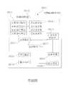
參閱第1A圖為本發明第一系統實施例的行動載具輔助系統0001方塊圖,以及第1B圖為所應用的行動載具0000係以車輛為例。如圖所示,本實施例之行動載具輔助系統0001至少包含一環境偵測裝置0010,該環境偵測裝置0010包含有一影像擷取模組0011、一儲存模組0012及一運算模組0013,其中,該影像擷取模組0011設置於該行動載具0000,該影像擷取模組0011用以擷取該行動載具0000周圍之環境影像,本實施例中,該影像擷取模組0011係設置於該行動載具0000前側,且用以擷取並產生該行動載具0000前向的環境影像。該行動載具0000前側可例如是車頭一側、車內前擋風玻璃附近或前保險桿處一側。較佳者,該影像擷取模組0011係設置於該行動載具0000的本體之幾何中心線i上,例如,位在車體橫向上的中心。影像擷取模組0011包含有一透鏡組與一影像感測元件,該透鏡組包含有至少兩片具有屈光力之透鏡用以成像至該影像感測元件而產生環境影像。環境影像之水平視角至少為45度。透鏡組的條件將於各光學實施例說明。Refer to Figure 1A for the block diagram of the mobilevehicle assist system 0001 according to the first system embodiment of the present invention, and Figure 1B for themobile vehicle 0000 used as an example of a vehicle. As shown in the figure, the mobilevehicle assistance system 0001 of this embodiment at least includes anenvironment detection device 0010, and theenvironment detection device 0010 includes animage capture module 0011, astorage module 0012, and anoperation module 0013 , Wherein theimage capturing module 0011 is set on themobile vehicle 0000, and theimage capturing module 0011 is used to capture an image of the environment around themobile vehicle 0000. In this embodiment, theimage capturing module 0011 is set in front of themobile vehicle 0000, and is used to capture and generate the forward environmental image of themobile vehicle 0000. The front side of themobile vehicle 0000 may be, for example, the front side of the vehicle, the side near the front windshield in the vehicle, or the side at the front bumper. Preferably, theimage capturing module 0011 is disposed on the geometric centerline i of the body of themobile vehicle 0000, for example, at the center of the vehicle body in the lateral direction. Theimage capturing module 0011 includes a lens group and an image sensor element, and the lens group includes at least two lenses with refractive power for imaging the image sensor element to generate environmental images. The horizontal viewing angle of the environmental image is at least 45 degrees. The conditions of the lens group will be described in each optical embodiment.

本實施例的環境偵測裝置0010更包含有一亮度感測器0014電性連接該影像擷取模組0011,用以至少對該影像擷取模組0011擷取影像之方向進行亮度偵測,且當該亮度感測器0014所測得之亮度大於一上閥值時,該影像擷取模組0011以降低進光量之方式擷取該環境影像,而當該亮度感測器0014所測得之亮度小於一下閥值時,該影像擷取模組0011以增加進光量之方式擷取該環境影像。藉此,可得到亮度適當的環境影像,避免過度曝光或曝光不足。Theenvironment detection device 0010 of this embodiment further includes abrightness sensor 0014 electrically connected to theimage capturing module 0011 for at least performing brightness detection on the direction in which theimage capturing module 0011 captures images, and When the brightness measured by thebrightness sensor 0014 is greater than an upper threshold, theimage capturing module 0011 captures the environment image by reducing the amount of light input, and when thebrightness sensor 0014 detects When the brightness is less than a threshold value, theimage capturing module 0011 captures the environment image by increasing the amount of light. In this way, an environment image with appropriate brightness can be obtained, and overexposure or underexposure can be avoided.

該儲存模組0012中儲存有複數圖像模型以及各該圖像模型對應之作動模式。該運算模組0013電性連接該影像擷取模組0011與該儲存模組0012,該運算模組0013偵測及判斷該環境影像中是否具有符合該等圖像模型之中至少其中一者之圖像,並產生對應之一偵測訊號。圖像可例如是行人、動物、交通號誌等。Thestorage module 0012 stores a plurality of image models and corresponding operation modes of each image model. Thecomputing module 0013 is electrically connected to theimage capturing module 0011 and thestorage module 0012, and thecomputing module 0013 detects and determines whether the environmental image matches at least one of the image models Image, and generate a corresponding detection signal. The image can be, for example, pedestrians, animals, traffic signs, etc.

本實施例中,行動載具輔助系統0001更包含一控制裝置0020,控制裝置0020設置於該行動載具0000並電性連接該運算模組0013與該儲存模組0012,該控制裝置0020接收到該環境影像中具有符合該等圖像模型之中至少其中一者之圖像的偵測訊號時,依據所符合之該或該等圖像模型對應之作動模式控制該行動載具0000作動,前述之作動包括控制行動載具0000的減速、煞車、加速等功能。In this embodiment, the mobilevehicle auxiliary system 0001 further includes acontrol device 0020. Thecontrol device 0020 is disposed on themobile vehicle 0000 and is electrically connected to thecomputing module 0013 and thestorage module 0012. Thecontrol device 0020 receives When the environmental image has a detection signal that matches the image of at least one of the image models, control the action of themobile vehicle 0000 according to the corresponding action mode of the corresponding image model or models. The actions include controlling the deceleration, braking, acceleration and other functions of themobile vehicle 0000.

本實施例中,該運算模組0013可依據環境影像偵測距離,更詳而言,該運算模組0013可偵測該行動載具0000與符合各該圖像模型之該或該等圖像之間的距離,並產生對應之偵測訊號;當該控制裝置0020接收到該行動載具0000與符合各該圖像模型之該或該等圖像之間的距離小於一安全距離之偵測訊號時,該控制裝置0020則以降低該行動載具0000速度之作動模式控制該行動載具0000,例如以減速或煞車之作動模式控制該行動載具0000。In this embodiment, thecalculation module 0013 can detect the distance based on environmental images. More specifically, thecalculation module 0013 can detect themobile vehicle 0000 and the image or images that match each image model. When thecontrol device 0020 receives themobile vehicle 0000 and the image or images conforming to the image model, the detection signal is less than a safe distance. When the signal is signaled, thecontrol device 0020 controls themobile vehicle 0000 in an operating mode that reduces the speed of themobile vehicle 0000, for example, controls themobile vehicle 0000 in an operating mode of deceleration or braking.

實務上,影像擷取模組0011之數量亦可為二個,該二影像擷取模組0011所擷取的環境影像之景深不同。該運算模組0013透過該二影像擷取模組0011所擷取並構成之立體的環境影像偵測是否具有符合該等圖像模型至少其中一者之圖像,以及各符合對應之圖像模型的圖像與該行動載具0000之間的距離,並產生對應之該偵測訊號。In practice, the number ofimage capturing modules 0011 can also be two, and the environmental images captured by the twoimage capturing modules 0011 have different depths of field. Thearithmetic module 0013 detects whether the three-dimensional environment image captured and constructed by the twoimage capturing modules 0011 has an image that conforms to at least one of the image models, and each conforms to the corresponding image model The distance between the image of and themobile vehicle 0000, and the corresponding detection signal is generated.

除了以環境影像偵測距離之外,該環境偵測裝置0010更包含有一偵測波收發模組0015與該運算模組0013電性連接,該偵測波收發模組0015至少對影像擷取模組0011擷取影像之方向(例如該行動載具的前方)發出一偵測波,並接收反射之偵測波。前述之偵測波可為超音波、毫米波雷達、光達、紅外光以及雷射之任一或組合。該運算模組0013更透過反射之偵測波偵測該行動載具與符合各該圖像模型之該或該等圖像之間的距離,並產生對應之該偵測訊號。藉此,以環境影像配合反射之測波確定安全距離的正確性。當該控制裝置0020接收小於該安全距離之偵測訊號時,該控制裝置0020則以降低該行動載具0000速度之作動模式控制該行動載具0000。In addition to detecting distances based on environmental images, theenvironmental detection device 0010 further includes a detectionwave transceiver module 0015 that is electrically connected to thecomputing module 0013, and the detectionwave transceiver module 0015 at least modulates theimage capture Group 0011 sends out a detection wave in the direction in which the image is captured (for example, the front of the mobile vehicle), and receives the reflected detection wave. The aforementioned detection wave can be any one or a combination of ultrasonic wave, millimeter wave radar, LiDAR, infrared light and laser. Thecalculation module 0013 further detects the distance between the mobile vehicle and the image or images conforming to the image model through the reflected detection wave, and generates the corresponding detection signal. In this way, the correctness of the safety distance is determined by the environmental image and reflected wave measurement. When thecontrol device 0020 receives a detection signal smaller than the safety distance, thecontrol device 0020 controls themobile vehicle 0000 in an actuation mode that reduces the speed of themobile vehicle 0000.

本實施例中,該運算模組0013更可透過反射之偵測波偵測所擷取方向中各物體的外輪廓,且該運算模組0013依一個或多個外輪廓與該等圖像模型配合,分析該環境影像中是否具有符合該等圖像模型至少其中一者之圖像,並產生對應之偵測訊號。In this embodiment, thecalculation module 0013 can detect the outer contour of each object in the captured direction through the reflected detection wave, and thecalculation module 0013 is based on one or more outer contours and the image models Cooperate, analyze whether the environment image has an image that meets at least one of the image models, and generate a corresponding detection signal.

為了對安全距離產生警示,行動載具輔助系統0001更包含有一警示模組0030電性連接該運算模組0013,該警示模組0030於該運算模組0013測得該行動載具0000與符合各該圖像模型之該或該等圖像之間的距離小於該安全距離時發出一警示訊息。In order to generate a warning for the safety distance, the mobilevehicle assistance system 0001 further includes awarning module 0030 that is electrically connected to thecalculation module 0013. Thewarning module 0030 and thecalculation module 0013 measure that themobile vehicle 0000 is consistent with each When the distance between the image or images of the image model is less than the safety distance, a warning message is sent out.

為了對應警示訊息提示駕駛者,行動載具輔助系統0001更包含電性連接該警示模組0030的一警示元件0040及一顯示裝置0050,警示元件0040供接收該警示訊息,且於該警示模組0030發出該警示訊息時產生對應之光線與聲音至少其中一者。前述警示元件可為蜂鳴器(Buzzer)或/及發光二極體(Light Emitting Diode,LED),其可分別設置於行動載具0000之左、右側,如A柱、左/右後視鏡、儀表板、前視玻璃等鄰近駕駛者座位之行動載具0000的內、外部區域,以對應位於行動載具0000的偵測狀況而啟動。In order to alert the driver in response to the warning message, the mobilevehicle assistance system 0001 further includes awarning element 0040 and adisplay device 0050 electrically connected to thewarning module 0030. Thewarning element 0040 is for receiving the warning message and is installed in the warning module. At least one of corresponding light and sound is generated when 0030 sends out the warning message. The aforementioned warning element can be a buzzer (Buzzer) or/and a light emitting diode (Light Emitting Diode, LED), which can be set on the left and right sides of themobile vehicle 0000, such as A-pillar, left/right rearview mirror The inner and outer areas of themobile vehicle 0000 near the driver’s seat, such as the dashboard, front glass, etc., are activated in response to the detection status of themobile vehicle 0000.

顯示裝置0050則是以用顯示該警示訊息,例如以圖像與文字至少其中一者之方式顯示。藉由警示元件0040及顯示裝置0050之其中一者提示駕駛者行動載具0000與符合圖像模型之圖像之間的距離小於該安全距離。Thedisplay device 0050 is used to display the warning message, for example, by displaying at least one of an image and a text. One of thewarning element 0040 and thedisplay device 0050 reminds the driver that the distance between themobile vehicle 0000 and the image conforming to the image model is less than the safe distance.

第1C圖繪示本實施例之顯示裝置0050的立體示意圖,其為具有顯示器的一車用電子後視鏡0100,第1D圖繪示第1C圖的短邊側剖面示意圖。在本發明之車用電子後視鏡0100可裝設於以交通工具為例的行動載具上,用以輔助交通工具的行駛,或是提供交通工具行駛的相關資訊,上述交通工具例如為車輛,車用電子後視鏡0100可為裝設於車輛內部的車用內後視鏡,或裝設於車輛外部的車用外後視鏡,兩者用以協助車輛駕駛者瞭解其他車輛的位置。本發明並不以此為限。除此之外,上述的交通工具並不限於車輛,上述交通工具也可指其他種類的交通工具,例如:陸地列車、飛行器、水上船艦等。FIG. 1C is a three-dimensional schematic diagram of thedisplay device 0050 of this embodiment, which is an electronicrearview mirror 0100 for a vehicle with a display, and FIG. 1D is a schematic diagram of a short side cross-sectional view of FIG. 1C. The electronic rear-view mirror 0100 for a vehicle of the present invention can be installed on a mobile vehicle such as a vehicle to assist the driving of the vehicle or provide information related to the driving of the vehicle. The vehicle is, for example, a vehicle , Car electronicrearview mirror 0100 can be a car interior rearview mirror installed inside the vehicle, or a car exterior rearview mirror installed outside the vehicle, both of which are used to help the vehicle driver understand the location of other vehicles . The present invention is not limited to this. In addition, the aforementioned means of transportation are not limited to vehicles, and the aforementioned means of transportation may also refer to other types of means of transportation, such as land trains, aircraft, and watercraft.

車用電子後視鏡0100組裝於一殻體0110中,且殻體0110具有開口(未繪示)。具體而言,殻體0110的開口與車用電子後視鏡0100的反射層0190重疊(第1C圖),藉此,外來光在通過開口後可傳遞至位於殻體0110內部的反射層0190,進而使車用電子後視鏡0100發揮反射鏡的功能。當車輛駕駛者在進行駕駛時,駕駛者例如是面對開口,且駕駛者可以觀看到由車用電子後視鏡0100反射而出的外來光,進而得知後方車輛的位置。The vehicle electronicrearview mirror 0100 is assembled in ahousing 0110, and thehousing 0110 has an opening (not shown). Specifically, the opening of thehousing 0110 overlaps with thereflective layer 0190 of the electronicrearview mirror 0100 for the vehicle (Figure 1C), whereby the external light can be transmitted to thereflective layer 0190 located inside thehousing 0110 after passing through the opening. Furthermore, the electronicrearview mirror 0100 for the vehicle functions as a mirror. When the driver of the vehicle is driving, for example, the driver is facing the opening, and the driver can see the external light reflected by the electronicrearview mirror 0100 for the vehicle, and then know the position of the vehicle behind.

請繼續參考第1D圖,車用電子後視鏡0100包括第一透光組件0120以及第二透光組件0130,該第一透光組件0120係朝向駕駛者,且第二透光組件0130設置於遠離駕駛者之一側。具體而言第一透光組件0120以及第二透光組件0130為透光基板,其材質例如可以是玻璃。然而第一透光組件0120以及第二透光組件0130的材質亦可以例如是塑膠、石英、PET基板或其他可適用的材料,其中該PET基板除具有封裝及保護效果外,另具有成本低、製造容易、極輕薄之特性。Please continue to refer to Figure 1D, the car electronicrearview mirror 0100 includes a first light-transmittingcomponent 0120 and a second light-transmittingcomponent 0130. The first light-transmittingcomponent 0120 is facing the driver, and the second light-transmittingcomponent 0130 is disposed at Keep away from the side of the driver. Specifically, the first light-transmittingcomponent 0120 and the second light-transmittingcomponent 0130 are light-transmitting substrates, and the material thereof may be glass, for example. However, the material of the first light-transmittingcomponent 0120 and the second light-transmittingcomponent 0130 can also be, for example, plastic, quartz, PET substrate or other applicable materials. In addition to the packaging and protection effects, the PET substrate also has low cost, Easy to manufacture, extremely thin and light.

在本實施例中,該第一透光組件0120係包含一第一收光面0122及一第一出光面0124,一來自於駕駛者後方之外來光影像係由該第一收光面0122入射至該第一透光組件0120,並由該第一出光面0124出射。該第二透光組件0130包含一第二收光面0132及一第二出光面0134,該第二收光面0132係相向於該第一出光面0124,並藉由一框膠0114與該第一出光面0124之間形成一間隙。前述外來光影像接續由該第一出光面0124出射至該第二透光組件0130,並由該第二出光面0134出射。In this embodiment, the first light-transmittingcomponent 0120 includes a first light-receivingsurface 0122 and a first light-emittingsurface 0124, and an external light image from behind the driver is incident from the first light-receivingsurface 0122 To the first light-transmittingcomponent 0120, and exit from the first light-emittingsurface 0124. The second light-transmittingcomponent 0130 includes a second light-receivingsurface 0132 and a second light-emittingsurface 0134. The second light-receivingsurface 0132 is opposite to the first light-emittingsurface 0124, and is connected to the first light-emittingsurface 0114 by aframe glue 0114. A gap is formed between a light-emittingsurface 0124. The aforementioned external light image is continuously emitted from the first light-emittingsurface 0124 to the second light-transmittingcomponent 0130, and then emitted from the second light-emittingsurface 0134.

一電光介質層0140係設置於該第一透光組件0120之第一出光面0124及該第二透光組件0130之第二收光面0132所形成之間隙中。至少一透光電極0150係配置於該第一透光組件0120以及該電光介質層0140之間。前述電光介質層0140配置於該第一透光組件0120以及至少一反射層0190之間。一透明導電層0160配置於該第一透光組件0120以及該電光介質層0140之間,另一透明導電層0160則配置於該第二透光組件0130以及該電光介質層0140之間。一電性連接件0170係與該透明導電層0160相連接,另一電性連接件0170則與透光電極0150相連接,以透光電極0150直接電性連接或透過另一透明導電層0160電性連接至光介質層0140,藉此可傳輸電能至該電光介質層0140,改變該電光介質層0140之透明度。當超過一亮度之外來光影像產生時,例如來自後方來車之強烈的車頭光線,與控制元件0180電性連接之眩光感測器0112可接收此光線能量並轉換成訊號,該控制元件0180可研判外來光影像之亮度是否超過一預設亮度,若產生眩光即藉由電性連接件0170對該電光介質層0140提供該電能以產生抗眩光效果。前述外來光影像若強度太強,將導致眩光效果而影響駕駛者眼睛的視線,進而危害行駛安全。An electro-optical medium layer 0140 is disposed in the gap formed by the first light-emittingsurface 0124 of the first light-transmittingelement 0120 and the second light-receivingsurface 0132 of the second light-transmittingelement 0130. At least onetransparent electrode 0150 is disposed between the firsttransparent component 0120 and the electro-optical medium layer 0140. The aforementioned electro-optical medium layer 0140 is disposed between the firsttransparent component 0120 and at least onereflective layer 0190. A transparentconductive layer 0160 is disposed between the first light-transmittingcomponent 0120 and the electro-optical medium layer 0140, and the other transparentconductive layer 0160 is disposed between the second light-transmittingcomponent 0130 and the electro-optical medium layer 0140. Oneelectrical connector 0170 is connected to the transparentconductive layer 0160, and the otherelectrical connector 0170 is connected to thetransparent electrode 0150. Thetransparent electrode 0150 is electrically connected directly or through another transparentconductive layer 0160. It is electrically connected to theoptical medium layer 0140, so that electrical energy can be transmitted to the electro-optical medium layer 0140, thereby changing the transparency of the electro-optical medium layer 0140. When an external light image with a brightness exceeding a brightness level is generated, such as strong headlight light from a car from behind, theglare sensor 0112 electrically connected to thecontrol element 0180 can receive the light energy and convert it into a signal. Thecontrol element 0180 can It is determined whether the brightness of the external light image exceeds a predetermined brightness. If glare is generated, theelectrical connection member 0170 is used to provide the electrical energy to the electro-optical medium layer 0140 to produce an anti-glare effect. If the intensity of the aforementioned external light image is too strong, it will cause glare effects and affect the sight of the driver's eyes, thereby endangering driving safety.

另外,前述透光電極0150以及反射層0190可例如是分別全面性覆蓋第一透光組件0120的表面以及第二透光組件0130的表面,本發明並不以此為限。在本實施例中,透光電極0150的材料可選用金屬氧化物,例如:銦錫氧化物、銦鋅氧化物、鋁錫氧化物、鋁鋅氧化物、銦鍺鋅氧化物、其它合適的氧化物、或者是上述至少二者的堆疊層。另外,反射層0190可具有導電性,反射層0190包含選自於銀(Ag)、銅(Cu)、鋁(Al)、鈦(Ti)、鉻(Cr)、鉬(Mo)所構成材料群組之至少一種材料或其合金,或包含二氧化矽或透明導電材料。或者,透光電極0150以及反射層0190亦可以包含其他種類的材料,本發明並不以此為限。In addition, thetransparent electrode 0150 and thereflective layer 0190 may, for example, completely cover the surface of the firsttransparent component 0120 and the surface of the secondtransparent component 0130, respectively, and the invention is not limited thereto. In this embodiment, the material of thetransparent electrode 0150 can be a metal oxide, such as indium tin oxide, indium zinc oxide, aluminum tin oxide, aluminum zinc oxide, indium germanium zinc oxide, and other suitable oxides. Or a stacked layer of at least two of the above. In addition, thereflective layer 0190 may have conductivity. Thereflective layer 0190 includes a material group selected from the group consisting of silver (Ag), copper (Cu), aluminum (Al), titanium (Ti), chromium (Cr), and molybdenum (Mo) At least one material in the group or its alloy, or contains silicon dioxide or a transparent conductive material. Alternatively, thetransparent electrode 0150 and thereflective layer 0190 may also include other types of materials, and the present invention is not limited thereto.

前述電光介質層0140可採用有機材料製作,亦可以採用無機材料製作,本發明並不以此為限。在本實施例中,電光介質層0140可選用電致變色材料(Electrochromic material),配置於第一透光組件0120以及第二透光組件0130之間,且配置於第一透光組件0120以及反射層0190之間。具體而言,透光電極0150配置於第一透光組件0120以及電光介質層0140 (電致變色材料層EC)之間,且本實施例的反射層0190可配置於第二透光組件0130以及電光介質層0140間。另外,在本實施例中,車用電子後視鏡0100更包括框膠0114。框膠0114位於第一透光組件0120與第二透光組件0130之間且環繞電光介質層0140。前述框膠0114、第一透光組件0120與第二透光組件0130共同封裝電光介質層0140。The aforementioned electro-optical medium layer 0140 may be made of organic materials, or may be made of inorganic materials, and the present invention is not limited thereto. In this embodiment, the electro-optical medium layer 0140 may be an electrochromic material, which is arranged between the first light-transmittingcomponent 0120 and the second light-transmittingcomponent 0130, and is arranged between the first light-transmittingcomponent 0120 and the reflective material. Between level 0190. Specifically, the light-transmittingelectrode 0150 is arranged between the first light-transmittingcomponent 0120 and the electro-optical medium layer 0140 (electrochromic material layer EC), and thereflective layer 0190 of this embodiment can be arranged on the second light-transmittingcomponent 0130 and 0140 between the electro-optical dielectric layer. In addition, in this embodiment, the electronicrearview mirror 0100 for a vehicle further includes aframe rubber 0114. Thesealant 0114 is located between the firsttransparent component 0120 and the secondtransparent component 0130 and surrounds the electro-optical medium layer 0140. Theaforementioned sealant 0114, the firsttransparent component 0120, and the secondtransparent component 0130 jointly encapsulate the electro-optical dielectric layer 0140.

在本實施例中,透明導電層0160,配置於電光介質層0140以及反射層0190之間。具體而言,可以作為反射層0190的抗氧化層並且可以避免電光介質層0140與反射層0190直接接觸,進而避免反射層0190受到有機材料的腐蝕,使得本實施例之車用電子後視鏡0100具有較長的使用壽命。此外前述框膠0114、透光電極0150以及透明導電層0160共同封裝電光介質層0140。在本實施例中,前述透明導電層0160包含選自於銦錫氧化物(indium tin oxide,ITO)、銦鋅氧化物(indium zinc oxide,IZO)或摻雜鋁的氧化鋅薄膜(Al-doped ZnO,AZO)、氟摻雜氧化錫所構成材料群組之至少一種材料。In this embodiment, the transparentconductive layer 0160 is disposed between the electro-optical medium layer 0140 and thereflective layer 0190. Specifically, it can be used as the anti-oxidation layer of thereflective layer 0190 and can prevent the electro-optical medium layer 0140 from directly contacting thereflective layer 0190, thereby preventing thereflective layer 0190 from being corroded by organic materials, so that the electronicrearview mirror 0100 of this embodiment Has a long service life. In addition, theaforementioned sealant 0114, thetransparent electrode 0150 and the transparentconductive layer 0160 jointly encapsulate the electro-optical medium layer 0140. In this embodiment, the aforementioned transparentconductive layer 0160 includes a thin film selected from indium tin oxide (ITO), indium zinc oxide (IZO), or Al-doped zinc oxide film (Al-doped zinc oxide). ZnO, AZO) and fluorine-doped tin oxide constitute at least one material in the group of materials.

在本實施例中,車用電子後視鏡0100可以選擇性地設置電性連接件0170例如導線或導電結構而分別連接至透光電極0150以及反射層0190。透光電極0150以及反射層0190可分別利用上述導線或導電結構與提供驅動訊號的至少一控制元件0180電性連接,進而驅動電光介質層0140。In this embodiment, the electronicrearview mirror 0100 for a vehicle can be selectively provided withelectrical connectors 0170, such as wires or conductive structures, to be connected to thetransparent electrode 0150 and thereflective layer 0190, respectively. The light-transmittingelectrode 0150 and thereflective layer 0190 can be electrically connected to at least onecontrol element 0180 that provides a driving signal through the above-mentioned wire or conductive structure, respectively, to drive the electro-optical medium layer 0140.

當電光介質層0140致能(enabled)時,電光介質層0140會發生電化學氧化還原反應而改變其能階,進而呈消光(diming)狀態。當外來光穿過殻體0110的開口進而到達電光介質層0140時,外來光會被呈消光狀態的電光介質層0140吸收,而使車用電子後視鏡0100切換至防眩光模式。另一方面,當電光介質層0140不致能時,電光介質層0140會呈透光狀態。此時,通過殻體0110開口的外來光會穿過電光介質層0140而被反射層0190反射,進而使車用電子後視鏡0100切換至鏡面模式。When the electro-optical medium layer 0140 is enabled, the electro-optical medium layer 0140 will undergo an electrochemical oxidation-reduction reaction to change its energy level, and then assume a diming state. When the external light passes through the opening of thehousing 0110 and reaches the electro-optic dielectric layer 0140, the external light will be absorbed by the electro-optic dielectric layer 0140 in a matte state, and the electronicrearview mirror 0100 for the vehicle is switched to the anti-glare mode. On the other hand, when the electro-optical medium layer 0140 is not enabled, the electro-optical medium layer 0140 will be in a light-transmitting state. At this time, the external light passing through the opening of thehousing 0110 will pass through the electro-optical medium layer 0140 and be reflected by thereflective layer 0190, thereby switching the automotive electronicrearview mirror 0100 to the mirror mode.

具體而言,第一透光組件0120具有遠離第二透光組件0130的第一收光面0122。來自後方其他車輛的外來光例如是由第一收光面0122進入車用電子後視鏡0100,且車用電子後視鏡0100反射外來光而使外來光由第一收光面0122離開車用電子後視鏡0100。另外,車輛駕駛者的人眼可以接收到經由車用電子後視鏡0100反射的外來光,進而瞭解後方其他車輛的位置。除此之外,反射層0190可選擇適當的材料以及設計適當的膜厚,而具有部分穿透部分反射的光學性質。Specifically, the first light-transmittingcomponent 0120 has a first light-receivingsurface 0122 far away from the second light-transmittingcomponent 0130. For example, the external light from other vehicles in the rear enters the electronic rear-view mirror 0100 from the first light-receivingsurface 0122, and the electronic rear-view mirror 0100 reflects the external light so that the external light leaves the vehicle through the first light-receivingsurface 0122. Electronicrearview mirror 0100. In addition, the human eyes of the vehicle driver can receive the external light reflected by the electronic rear-view mirror 0100 for the vehicle to understand the location of other vehicles behind. In addition, thereflective layer 0190 can be selected from an appropriate material and designed with an appropriate film thickness, and has the optical properties of partial penetration and partial reflection.

車用電子後視鏡0100之顯示器可為LCD或LED,顯示器可設置殻體0110內部或外部,例如設置於第二透光組件0130遠離第一透光組件0120的一側,或例如是第二透光組件0130遠離第一透光組件0120之第二出光面0134。由於反射層0190具有部分穿透部分反射的光學性質,因此顯示器發出的影像光可以穿過反射層0190,進而讓使用者可觀看到顯示器顯示的內部影像,以顯示警示訊息。The display of the car electronicrearview mirror 0100 can be LCD or LED, and the display can be set inside or outside thehousing 0110, for example, on the side of the second light-transmittingcomponent 0130 away from the first light-transmittingcomponent 0120, or for example the second The light-transmittingcomponent 0130 is far away from the second light-emittingsurface 0134 of the first light-transmittingcomponent 0120. Since thereflective layer 0190 has the optical properties of partial penetration and partial reflection, the image light emitted by the display can pass through thereflective layer 0190, so that the user can view the internal image displayed on the display to display warning messages.

實務上,影像擷取模組0011亦可設置於該行動載具0000後側,且用以擷取並產生該行動載具0000後向的環境影像,該行動載具0000後側可例如是後車箱一側或後保險桿處一側。較佳者,係設置於該行動載具0000的本體之幾何中心線上,例如,設置在車體橫向的中心。後向的環境影像之水平視角至少為100度。In practice, theimage capturing module 0011 can also be installed on the back side of themobile vehicle 0000, and used to capture and generate the backward environmental image of themobile vehicle 0000. The back side of themobile vehicle 0000 can be, for example, the rear The side of the car box or the side of the rear bumper. Preferably, it is set on the geometric centerline of the body of themobile vehicle 0000, for example, on the center of the vehicle body transversely. The horizontal viewing angle of the backward environment image is at least 100 degrees.

藉由上述之行動載具輔助系統,即可進行本實施例的控制方法,該控制方法至少包含第1E圖所示之下步驟:The control method of this embodiment can be implemented by the above-mentioned mobile vehicle auxiliary system, and the control method includes at least the following steps shown in Figure 1E:

影像擷取模組0011持續擷取該行動載具0000周圍之環境影像;Theimage capture module 0011 continuously captures the environment image around themobile vehicle 0000;

由運算模組0013接收該環境影像;The environment image is received by thecomputing module 0013;

運算模組0013偵測環境影像中是否具有符合該儲存模組0012所儲存之該些圖像模型其中一者之圖像:Thecomputing module 0013 detects whether there is an image that matches one of the image models stored in thestorage module 0012 in the environment image:

若是:運算模組0013輸出對應之偵測訊號,且影像擷取模組0011繼續擷取環境影像。If yes: thecomputing module 0013 outputs the corresponding detection signal, and theimage capturing module 0011 continues to capture environmental images.

若否:影像擷取模組0011繼續擷取環境影像。If not: theimage capturing module 0011 continues to capture environmental images.

於後提供該運算模組0013可行的多種演算法,使該運算模組0013判斷環境影像中具有符合該儲存模組0012所儲存之該些圖像模型其中一者之圖像。A variety of feasible algorithms for theoperation module 0013 is provided later, so that theoperation module 0013 determines that the environment image has an image that matches one of the image models stored in thestorage module 0012.

(1)請配合第1F圖,該運算模組0013係將該環境影像切分成複數區塊B0,並依預定順序循環偵測該等區塊B0之部分區塊B1中是否具有符合該等圖像模型至少其中一者之圖像(如第1F圖中所示的行人0060、動物0061或交通號誌0062),並依據符合該等圖像模型之區塊B0之位置產生對應之該偵測訊號。例如,可採用CNN演算法進行判斷。(1) Please cooperate with Fig. 1F. Theoperation module 0013 divides the environmental image into a plurality of blocks B0, and cyclically detects whether there is a part of the block B1 in the block B0 in a predetermined sequence. Image of at least one of the image models (such aspedestrian 0060,animal 0061, ortraffic sign 0062 shown in Figure 1F), and generate the corresponding detection based on the location of the block B0 matching the image models Signal. For example, the CNN algorithm can be used for judgment.

(2)該運算模組0013係將該環境影像切分成複數區塊,並偵測各該區塊中是否具有符合該等圖像模型至少其中一者之圖像,並依據各區塊之位置產生對應之該偵測訊號。例如,可採用R-CNN演算法進行判斷。(2) Thecalculation module 0013 divides the environment image into a plurality of blocks, and detects whether each block has an image that conforms to at least one of the image models, and based on the position of each block Generate the corresponding detection signal. For example, the R-CNN algorithm can be used for judgment.

(3)該運算模組0013係於該環境影像中設定一基準點,並以該基準點為中心設定數個不同尺寸的區塊,並偵測各該區塊中是否具有符合該等圖像模型至少其中一者之圖像,並依據各區塊之位置產生對應之該偵測訊號。例如,可採用Faster R-CNN演算法進行判斷。(3) Thecalculation module 0013 sets a reference point in the environmental image, and sets several blocks of different sizes with the reference point as the center, and detects whether each of the blocks matches the images The image of at least one of the models is generated, and the corresponding detection signal is generated according to the position of each block. For example, the Faster R-CNN algorithm can be used for judgment.

(4)該運算模組0013係先將該環境影像中各物體之影像分別以一色彩遮罩沿其輪廓取代,且各色彩遮罩之顏色不同於其他色彩遮罩,並以各色彩遮罩之形狀分析是否有符合之圖像模型並產生對應之該偵測訊號。例如,可採用Mask R-CNN演算法進行判斷。(4) Thecalculation module 0013 first replaces the image of each object in the environment image with a color mask along its outline, and the color of each color mask is different from other color masks, and uses each color mask The shape analyzes whether there is a matching image model and generates the corresponding detection signal. For example, the Mask R-CNN algorithm can be used for judgment.

(5)該運算模組0013係將該環境影像切分成複數區塊,並以每個區塊中心點為基準,發散偵測各該區塊中是否具有符合該等圖像模型至少其中一者之圖像,並依據各區塊之位置產生對應之該偵測訊號。例如,可採用YOLO演算法進行判斷。(5) Thecalculation module 0013 divides the environment image into a plurality of blocks, and uses the center point of each block as a reference, divergently detects whether each block has at least one of the image models The corresponding detection signal is generated according to the position of each block. For example, the YOLO algorithm can be used for judgment.

(6)在該儲存模組0012所儲存之該等圖像模型為灰階值模型,而該運算模組0013係將該環境影像進行灰階處理,且依據各像素之灰階值偵測各該區塊中是否具有符合該等圖像模型至少其中一者之圖像並產生對應之該偵測訊號。例如,可採用灰階特徵演算法進行判斷。(6) The image models stored in thestorage module 0012 are grayscale value models, and thearithmetic module 0013 performs grayscale processing on the environmental image, and detects each pixel based on the grayscale value of each pixel. Whether the block has an image that meets at least one of the image models and generates the corresponding detection signal. For example, the gray-scale feature algorithm can be used for judgment.

(7)在該儲存模組0012所儲存之該等圖像模型為三原色色階值模型,而該運算模組0013係將該環境影像進行三原色濾鏡處理,且依據各像素之各原色的色階值偵測各該區塊中是否具有符合該等圖像模型至少其中一者之圖像並產生對應之該偵測訊號。例如,可採用三原色特徵演算法進行判斷。(7) The image models stored in thestorage module 0012 are three-primary-color gradation value models, and thearithmetic module 0013 performs three-primary-color filter processing on the environmental image, and is based on the color of each primary color of each pixel The level value detects whether there is an image that meets at least one of the image models in each block and generates the corresponding detection signal. For example, the three primary color feature algorithm can be used for judgment.

(8)該運算模組0013對該環境影像分析前處理,係先對該環境影像進行幾何轉換、幾何校正、空間轉換、色彩轉換、對比強化、雜訊去除、平滑化、銳利化與亮度調整至少一者,再偵測該環境影像中是否具有符合該儲存模組0012所儲存之該等圖像模型其中一者之圖像,並輸出對應之偵測訊號。(8) Thecalculation module 0013 analyzes the environmental image before processing, and first performs geometric conversion, geometric correction, space conversion, color conversion, contrast enhancement, noise removal, smoothing, sharpening and brightness adjustment of the environmental image. At least one of them is to detect whether there is an image matching one of the image models stored in thestorage module 0012 in the environment image, and output a corresponding detection signal.

(9)該運算模組0013對該環境影像作輪廓特徵擷取,係先對該環境影像進行點、線、邊、角、區域等特徵至少一者進行擷取,再利用所擷取之特徵偵測該環境影像中是否具有符合該儲存模組0012所儲存之該等圖像模型其中一者之圖像,並輸出對應之偵測訊號。(9) Thearithmetic module 0013 extracts contour features of the environmental image, first extracts at least one of the points, lines, edges, corners, and regions of the environmental image, and then uses the captured features Detect whether the environmental image has an image that matches one of the image models stored in thestorage module 0012, and output a corresponding detection signal.

(10)該運算模組0013對該環境影像作紋理分析,係先依據該環境影像之紋理區分出各區塊,再依據各區塊之輪廓形狀偵測該環境影像中是否具有符合該儲存模組0012所儲存之該等圖像模型其中一者之圖像,並輸出對應之偵測訊號。(10) Thecomputing module 0013 performs texture analysis on the environmental image, first distinguishes each block according to the texture of the environmental image, and then detects whether the environmental image has a storage model that matches the contour shape of each block.Group 0012 stores the image of one of the image models, and outputs the corresponding detection signal.

(11)該運算模組0013對該環境影像作梯度影像處理,係先將該環境影像轉換成水平梯度影像與垂直梯度影像,並依據水平梯度影像與垂直梯度影像取得該環境影像中複數物件之各別的輪廓形狀,再依據各該輪廓形狀偵測是否符合該儲存模組0012所儲存之該等圖像模型其中一者之圖像,並輸出對應之偵測訊號。(11) Thecomputing module 0013 performs gradient image processing on the environment image, first converts the environment image into a horizontal gradient image and a vertical gradient image, and obtains the plurality of objects in the environment image according to the horizontal gradient image and the vertical gradient image The respective contour shapes are then detected according to the contour shapes whether they match the image of one of the image models stored in thestorage module 0012, and the corresponding detection signal is output.

(12)該儲存模組0012所儲存有複數圖像類別,且各圖像類別具有該等圖像模型,該運算模組0013對該環境影像作物件分類,該運算模組0013偵測該環境影像中是否具有符合該儲存模組0012所儲存之該等圖像模型其中一者之圖像後,再分析符合之圖像模型所屬的圖像類別,並依分析結果輸出對應之偵測訊號。此外,控制方法更包含透過一更新裝置(圖未示)連接至該儲存模組0012,以更新該儲存模組0012所儲存的該些圖像類別之至少一者,及/或該些圖像模型之至少一者。(12) Thestorage module 0012 stores a plurality of image categories, and each image category has the image models, thecalculation module 0013 classifies the environmental image crop, and thecalculation module 0013 detects the environment After the image has an image that matches one of the image models stored in thestorage module 0012, the image type of the matched image model is analyzed, and the corresponding detection signal is output according to the analysis result. In addition, the control method further includes connecting to thestorage module 0012 through an update device (not shown) to update at least one of the image categories stored in thestorage module 0012, and/or the images At least one of the models.

藉由上述之多種演算法之任一者,該運算模組0013即可判斷環境影像中具有符合該儲存模組0012所儲存之該些圖像模型其中一者之圖像,並輸出偵測訊號。該運算模組0013並不限定以上述之演算法判斷環境影像。By any of the above-mentioned multiple algorithms, thecomputing module 0013 can determine that the environment image has an image that matches one of the image models stored in thestorage module 0012, and output a detection signal . Thecalculation module 0013 does not limit the judgment of the environment image by the aforementioned algorithm.

本實施例的控制方法更包含:該控制裝置0020接收到該環境影像中具有符合該等圖像模型至少其中一者之圖像的偵測訊號時,依據所符合之該或該些該圖像模型自該儲存模組提取對應之作動模式控制該行動載具0000作動。The control method of this embodiment further includes: when thecontrol device 0020 receives a detection signal of an image that matches at least one of the image models in the environmental image, it is based on the matched image model(s) The corresponding action mode is extracted from the storage module to control the action of themobile vehicle 0000.

舉例而言,該運算模組0013更偵測該行動載具0000與符合各該圖像模型之該或該等圖像之間的距離,並產生對應之該偵測訊號;若該控制裝置0020接收到該行動載具0000與符合各該圖像模型之該或該等圖像之間的距離小於一安全距離之偵測訊號時,則以降低該行動載具0000速度之作動模式(例如減速或煞車之作動模式)控制該行動載具0000作動。For example, thearithmetic module 0013 further detects the distance between themobile vehicle 0000 and the image or images matching each of the image models, and generates the corresponding detection signal; if thecontrol device 0020 When receiving a detection signal that the distance between themobile vehicle 0000 and the image or images conforming to each of the image models is less than a safe distance, the operating mode of reducing the speed of the mobile vehicle 0000 (such as decelerating Or brake action mode) to control the action of themobile vehicle 0000.

參閱第1G圖以及第1H圖,第1G圖為本發明第二系統實施例的行動載具0000’,第1H圖為本發明第二系統實施例的行動載具輔助系統0001’方塊圖。Referring to Figure 1G and Figure 1H, Figure 1G is a mobile vehicle 0000' according to the second system embodiment of the present invention, and Figure 1H is a block diagram of the mobile vehicle assistance system 0001' according to the second system embodiment of the present invention.

本實施例的行動載具輔助系統0001’具有大致相同於第一系統實施例之架構,不同的是環境偵測裝置0010之至少一影像擷取模組0011之數量為四,該等影像擷取模組0011分別設置於該行動載具0000’之前側、後側、左側與右側,用以擷取並產生該行動載具0000’前向、後向、左向與右向之環境影像,本實施例中,該行動載具0000’前側可例如是車頭一側、車內前擋風玻璃附近或前保險桿處一側;後側可例如是後車箱一側或後保險桿處一側;左側可以例如是左後視鏡;右側可以例如是右後視鏡。The mobile vehicle assistance system 0001' of this embodiment has substantially the same structure as the first system embodiment, except that the number of at least oneimage capturing module 0011 of theenvironment detection device 0010 is four, and the image capturing Themodule 0011 is respectively set on the front, rear, left and right sides of the mobile vehicle 0000' to capture and generate the forward, backward, left and right environmental images of the mobile vehicle 0000'. In an embodiment, the front side of the mobile vehicle 0000' can be, for example, the front side of the vehicle, near the front windshield in the car, or the side of the front bumper; the rear side can be, for example, the side of the trunk or the side of the rear bumper ; The left side can be, for example, a left rearview mirror; the right side can, for example, be a right rearview mirror.

該運算模組0013偵測該等影像擷取模組0011所擷取並組合構成之環境影像中是否具有符合該等圖像模型至少其中一者之圖像,並產生對應之偵測訊號。組合構成之環境影像涵蓋之水平視角為360度,組合構成之環境影像可以由運算模組0013進行組合。Thearithmetic module 0013 detects whether there is an image that matches at least one of the image models in the environmental images captured and combined by theimage capturing modules 0011, and generates a corresponding detection signal. The horizontal viewing angle covered by the combined environment image is 360 degrees, and the combined environment image can be combined by thecomputing module 0013.

本實施例的行動載具輔助系統0001’同樣可以應用第一系統實施例的控制方法,於此容不贅述。The mobile vehicle assistance system 0001' of this embodiment can also apply the control method of the first system embodiment, which will not be repeated here.

上述中,是以四個影像擷取模組0011為例說明,實務上,影像擷取模組0011數量亦可為二個且分別設置於該行動載具0000’左右兩側,用以擷取於該行動載具0000’左向與右向之環境影像。該運算模組0013係偵測該行動載具0000’左向與右向之該環境影像中是否具有符合該等圖像模型至少其中一者之圖像並產生對應之該偵測訊號。In the above description, fourimage capture modules 0011 are taken as an example. In practice, the number ofimage capture modules 0011 can also be two and they are respectively set on the left and right sides of the mobile vehicle 0000' for capturing The left and right environmental images of the mobile vehicle 0000'. Thecalculation module 0013 detects whether the environmental image of the mobile vehicle 0000' to the left and the right has an image that matches at least one of the image models and generates the corresponding detection signal.

實務上,設置於該行動載具0000’左右兩側的二個影像擷取模組0011亦可朝向該行動載具0000’前向之位置上以擷取並產生該行動載具0000’前向的環境影像。或者,設置於該行動載具0000’左右兩側且朝向該行動載具0000’後向之位置上,以擷取並產生該行動載具0000’後向的環境影像。無論是朝向前向或後向,二個環境影像涵蓋之水平視角至少為180度。In practice, the twoimage capturing modules 0011 arranged on the left and right sides of the mobile vehicle 0000' can also face the forward position of the mobile vehicle 0000' to capture and generate the forward direction of the mobile vehicle 0000' Environment image. Or, it is arranged on the left and right sides of the mobile vehicle 0000' and facing backwards of the mobile vehicle 0000' to capture and generate the backward environmental image of the mobile vehicle 0000'. Whether facing forward or backward, the horizontal viewing angle covered by the two environmental images is at least 180 degrees.

實務上,影像擷取模組0011之數量亦可為三個。該等影像擷取模組0011分別設置於該行動載具0000’之前側、左側與右側,用以擷取並產生該行動載具0000’前向、左向與右向之環境影像。該運算模組係偵測該等影像擷取模組0011所擷取並組合構成之環境影像中是否具有符合該等圖像模型至少其中一者之圖像,並產生對應之偵測訊號。組合構成之環境影像可以由運算模組0013進行組合。In practice, the number ofimage capture modules 0011 can also be three. Theimage capturing modules 0011 are respectively arranged on the front, left and right sides of the mobile vehicle 0000' to capture and generate the forward, left and right environmental images of the mobile vehicle 0000'. The arithmetic module detects whether there is an image that matches at least one of the image models in the environmental image captured and combined by theimage capturing modules 0011, and generates a corresponding detection signal. The combined environment image can be combined by thecomputing module 0013.

以下茲就該透鏡組可行之光學實施例進行說明。於本發明透鏡組所形成之光學成像系統可使用三個工作波長進行設計,分別為486.1 nm、587.5 nm、656.2 nm,其中587.5 nm為主要參考波長為主要提取技術特徵之參考波長。光學成像系統亦可使用五個工作波長進行設計,分別為470 nm、510 nm、555 nm、610 nm、650 nm,其中555 nm為主要參考波長為主要提取技術特徵之參考波長。Hereinafter, possible optical embodiments of the lens group will be described. The optical imaging system formed by the lens group of the present invention can be designed with three working wavelengths, namely 486.1 nm, 587.5 nm, and 656.2 nm, of which 587.5 nm is the main reference wavelength as the reference wavelength for the main extraction of technical features. The optical imaging system can also be designed with five working wavelengths, namely 470 nm, 510 nm, 555 nm, 610 nm, and 650 nm, of which 555 nm is the main reference wavelength for the main extraction technology.

光學成像系統的焦距f與每一片具有正屈折力之透鏡的焦距fp之比值PPR,光學成像系統的焦距f與每一片具有負屈折力之透鏡的焦距fn之比值NPR,所有正屈折力之透鏡的PPR總和為ΣPPR,所有負屈折力之透鏡的NPR總和為ΣNPR,當滿足下列條件時有助於控制光學成像系統的總屈折力以及總長度:0.5≦ΣPPR/│ΣNPR│≦15,較佳地,可滿足下列條件:1≦ΣPPR/│ΣNPR│≦3.0。The ratio of the focal length f of the optical imaging system to the focal length fp of each lens with positive refractive power PPR, the ratio of the focal length f of the optical imaging system to the focal length fn of each lens with negative refractive power NPR, all lenses with positive refractive power The sum of PPR is ΣPPR, and the sum of NPR of all negative refractive power lenses is ΣNPR. When the following conditions are met, it will help control the total refractive power and total length of the optical imaging system: 0.5≦ΣPPR/│ΣNPR│≦15, better It can meet the following conditions: 1≦ΣPPR/│ΣNPR│≦3.0.

光學成像系統可更包含一影像感測元件,其設置於成像面。影像感測元件有效感測區域對角線長的一半(即為光學成像系統之成像高度或稱最大像高) 為HOI,第一透鏡物側面至成像面於光軸上的距離為HOS,其滿足下列條件:HOS/HOI≦50;以及0.5≦HOS/f≦150。較佳地,可滿足下列條件:1≦HOS/HOI≦40;以及1≦HOS/f≦140。藉此,可維持光學成像系統的小型化,以搭載於輕薄可攜式的電子產品上。The optical imaging system may further include an image sensing element disposed on the imaging surface. The half of the diagonal length of the effective sensing area of the image sensor element (that is, the imaging height or maximum image height of the optical imaging system) is HOI, and the distance from the object side of the first lens to the imaging surface on the optical axis is HOS, which Meet the following conditions: HOS/HOI≦50; and 0.5≦HOS/f≦150. Preferably, the following conditions can be satisfied: 1≦HOS/HOI≦40; and 1≦HOS/f≦140. In this way, the miniaturization of the optical imaging system can be maintained to be mounted on thin and portable electronic products.

另外,本發明的光學成像系統中,依需求可設置至少一光圈,以減少雜散光,有助於提昇影像品質。In addition, in the optical imaging system of the present invention, at least one aperture can be set as required to reduce stray light and help improve image quality.

本發明的光學成像系統中,光圈配置可為前置光圈或中置光圈,其中前置光圈意即光圈設置於被攝物與第一透鏡間,中置光圈則表示光圈設置於第一透鏡與成像面間。若光圈為前置光圈,可使光學成像系統的出瞳與成像面產生較長的距離而容置更多光學元件,並可增加影像感測元件接收影像的效率;若為中置光圈,係有助於擴大系統的視場角,使光學成像系統具有廣角鏡頭的優勢。前述光圈至成像面間的距離為InS,其滿足下列條件:0.1≦InS/HOS≦1.1。藉此,可同時兼顧維持光學成像系統的小型化以及具備廣角的特性。In the optical imaging system of the present invention, the aperture configuration can be a front aperture or a center aperture, where the front aperture means that the aperture is set between the subject and the first lens, and the middle aperture means that the aperture is set between the first lens and the first lens. Between imaging surfaces. If the aperture is a front aperture, the exit pupil of the optical imaging system and the imaging surface can produce a longer distance to accommodate more optical elements, and can increase the efficiency of image sensing elements to receive images; if it is a central aperture, the system It helps to expand the field of view of the system, so that the optical imaging system has the advantage of a wide-angle lens. The distance between the aforementioned aperture and the imaging surface is InS, which satisfies the following conditions: 0.1≦InS/HOS≦1.1. In this way, the miniaturization of the optical imaging system and the wide-angle characteristics can be maintained at the same time.

本發明的光學成像系統中,第一透鏡物側面至第六透鏡像側面間的距離為InTL,於光軸上所有具屈折力之透鏡的厚度總和為ΣTP,其滿足下列條件:0.1≦ΣTP/InTL≦0.9。藉此,當可同時兼顧系統成像的對比度以及透鏡製造的良率並提供適當的後焦距以容置其他元件。In the optical imaging system of the present invention, the distance between the object side of the first lens and the image side of the sixth lens is InTL, and the total thickness of all refractive lenses on the optical axis is ΣTP, which satisfies the following conditions: 0.1≦ΣTP/ InTL≦0.9. In this way, the contrast of the system imaging and the yield rate of lens manufacturing can be taken into account at the same time, and an appropriate back focus can be provided to accommodate other components.

第一透鏡物側面的曲率半徑為R1,第一透鏡像側面的曲率半徑為R2,其滿足下列條件:0.001≦│R1/R2│≦25。藉此,第一透鏡的具備適當正屈折力強度,避免球差增加過速。較佳地,可滿足下列條件:0.01≦│R1/R2│<12。The radius of curvature of the object side of the first lens is R1, and the radius of curvature of the image side of the first lens is R2, which meets the following conditions: 0.001≦│R1/R2│≦25. In this way, the first lens has a proper positive refractive power strength to avoid excessive increase in spherical aberration. Preferably, the following conditions can be satisfied: 0.01≦│R1/R2│<12.

第六透鏡物側面的曲率半徑為R11,第六透鏡像側面的曲率半徑為R12,其滿足下列條件:-7 <(R11-R12)/(R11+R12)<50。藉此,有利於修正光學成像系統所產生的像散。The radius of curvature of the object side surface of the sixth lens is R11, and the radius of curvature of the image side surface of the sixth lens is R12, which satisfies the following conditions: -7<(R11-R12)/(R11+R12)<50. This is beneficial to correct the astigmatism generated by the optical imaging system.

第一透鏡與第二透鏡於光軸上的間隔距離為IN12,其滿足下列條件:IN12 / f ≦60藉此,有助於改善透鏡的色差以提升其性能。The distance between the first lens and the second lens on the optical axis is IN12, which satisfies the following condition: IN12 / f ≦60, thereby helping to improve the chromatic aberration of the lens and improve its performance.

第五透鏡與第六透鏡於光軸上的間隔距離為IN56,其滿足下列條件:IN56 / f ≦3.0,有助於改善透鏡的色差以提升其性能。The distance between the fifth lens and the sixth lens on the optical axis is IN56, which satisfies the following condition: IN56 / f ≦3.0, which helps to improve the chromatic aberration of the lens and improve its performance.

第一透鏡與第二透鏡於光軸上的厚度分別為TP1以及TP2,其滿足下列條件:0.1≦(TP1+IN12) / TP2≦10。藉此,有助於控制光學成像系統製造的敏感度並提升其性能。The thickness of the first lens and the second lens on the optical axis are respectively TP1 and TP2, which satisfy the following conditions: 0.1≦(TP1+IN12) / TP2≦10. This helps to control the sensitivity of the optical imaging system manufacturing and improve its performance.

第五透鏡與第六透鏡於光軸上的厚度分別為TP5以及TP6,前述兩透鏡於光軸上的間隔距離為IN56,其滿足下列條件:0.1≦(TP6+IN56) / TP5≦15藉此,有助於控制光學成像系統製造的敏感度並降低系統總高度。The thickness of the fifth lens and the sixth lens on the optical axis are TP5 and TP6, respectively. The separation distance between the two lenses on the optical axis is IN56, which meets the following conditions: 0.1≦(TP6+IN56) / TP5≦15 , Help control the sensitivity of optical imaging system manufacturing and reduce the overall height of the system.

第二透鏡、第三透鏡與第四透鏡於光軸上的厚度分別為TP2、TP3以及TP4,第二透鏡與第三透鏡於光軸上的間隔距離為IN23,第四透鏡與第五透鏡於光軸上的間隔距離為IN45,其滿足下列條件:0.1≦TP4/ (IN34+TP4+IN45)<1。藉此,有助層層微幅修正入射光行進過程所產生的像差並降低系統總高度。The thickness of the second lens, the third lens, and the fourth lens on the optical axis are TP2, TP3, and TP4, respectively. The distance between the second lens and the third lens on the optical axis is IN23. The fourth lens and the fifth lens are at The separation distance on the optical axis is IN45, which satisfies the following conditions: 0.1≦TP4/(IN34+TP4+IN45)<1. In this way, it helps to slightly correct the aberrations caused by the incident light traveling process and reduce the overall height of the system.

本發明的光學成像系統中,第六透鏡物側面的臨界點C61與光軸的垂直距離為 HVT61,第六透鏡像側面的臨界點C62與光軸的垂直距離為HVT62,第六透鏡物側面於光軸上的交點至臨界點C61位置於光軸的水平位移距離為SGC61,第六透鏡像側面於光軸上的交點至臨界點C62位置於光軸的水平位移距離為SGC62,可滿足下列條件:0 mm≦HVT61≦3 mm;0 mm < HVT62≦6 mm;0≦HVT61/HVT62;0 mm≦∣SGC61∣≦0.5 mm;0 mm<∣SGC62∣≦2 mm;以及0 <∣SGC62∣/(∣SGC62∣+TP6)≦0.9。藉此,可有效修正離軸視場的像差。In the optical imaging system of the present invention, the vertical distance between the critical point C61 on the object side of the sixth lens and the optical axis is HVT61; the vertical distance between the critical point C62 on the image side of the sixth lens and the optical axis is HVT62; The horizontal displacement distance from the intersection on the optical axis to the critical point C61 on the optical axis is SGC61, and the horizontal displacement from the intersection of the sixth lens image side surface on the optical axis to the critical point C62 on the optical axis is SGC62, which can meet the following conditions :0 mm≦HVT61≦3 mm; 0 mm <HVT62≦6 mm; 0≦HVT61/HVT62; 0 mm≦∣SGC61∣≦0.5 mm; 0 mm<∣SGC62∣≦2 mm; and 0 <∣SGC62∣/ (∣SGC62∣+TP6)≦0.9. In this way, the aberration of the off-axis field of view can be effectively corrected.

本發明的光學成像系統其滿足下列條件:0.2≦HVT62/ HOI≦0.9。較佳地,可滿足下列條件:0.3≦HVT62/ HOI≦0.8。藉此,有助於光學成像系統之週邊視場的像差修正。The optical imaging system of the present invention satisfies the following conditions: 0.2≦HVT62/HOI≦0.9. Preferably, the following conditions can be satisfied: 0.3≦HVT62/HOI≦0.8. This helps to correct the aberration of the peripheral field of view of the optical imaging system.

本發明的光學成像系統其滿足下列條件:0≦HVT62/ HOS≦0.5。較佳地,可滿足下列條件:0.2≦HVT62/ HOS≦0.45。藉此,有助於光學成像系統之週邊視場的像差修正。The optical imaging system of the present invention satisfies the following conditions: 0≦HVT62/HOS≦0.5. Preferably, the following conditions can be satisfied: 0.2≦HVT62/HOS≦0.45. This helps to correct the aberration of the peripheral field of view of the optical imaging system.

本發明的光學成像系統中,第六透鏡物側面於光軸上的交點至第六透鏡物側面最近光軸的反曲點之間與光軸平行的水平位移距離以SGI611表示,第六透鏡像側面於光軸上的交點至第六透鏡像側面最近光軸的反曲點之間與光軸平行的水平位移距離以SGI621表示,其滿足下列條件:0 < SGI611 /( SGI611+TP6)≦0.9;0 < SGI621 /( SGI621+TP6)≦0.9。較佳地,可滿足下列條件:0.1≦SGI611 /( SGI611+TP6)≦0.6;0.1≦SGI621 /( SGI621+TP6)≦0.6。In the optical imaging system of the present invention, the horizontal displacement distance parallel to the optical axis between the intersection of the sixth lens object side surface on the optical axis and the closest optical axis inflection point of the sixth lens object side surface is represented by SGI611, and the sixth lens image The horizontal displacement distance parallel to the optical axis from the intersection point of the side surface on the optical axis to the inflection point of the closest optical axis of the sixth lens image side is represented by SGI621, which meets the following conditions: 0 <SGI611 /( SGI611+TP6)≦0.9 ; 0 <SGI621 /( SGI621+TP6)≦0.9. Preferably, the following conditions can be satisfied: 0.1≦SGI611/(SGI611+TP6)≦0.6; 0.1≦SGI621/(SGI621+TP6)≦0.6.

第六透鏡物側面於光軸上的交點至第六透鏡物側面第二接近光軸的反曲點之間與光軸平行的水平位移距離以SGI612表示,第六透鏡像側面於光軸上的交點至第六透鏡像側面第二接近光軸的反曲點之間與光軸平行的水平位移距離以SGI622表示,其滿足下列條件:0 < SGI612/( SGI612+TP6)≦0.9;0 < SGI622 /( SGI622+TP6)≦0.9。較佳地,可滿足下列條件:0.1≦SGI612 /( SGI612+TP6)≦0.6;0.1≦SGI622 /( SGI622+TP6)≦0.6。The horizontal displacement distance parallel to the optical axis from the intersection point of the sixth lens object side on the optical axis to the second inflection point of the sixth lens object side close to the optical axis is represented by SGI612. The sixth lens image side is on the optical axis. The horizontal displacement distance parallel to the optical axis from the intersection point to the second inflection point on the image side of the sixth lens that is parallel to the optical axis is represented by SGI622, which satisfies the following conditions: 0 <SGI612/( SGI612+TP6)≦0.9; 0 <SGI622 /( SGI622+TP6)≦0.9. Preferably, the following conditions can be satisfied: 0.1≦SGI612/(SGI612+TP6)≦0.6; 0.1≦SGI622/(SGI622+TP6)≦0.6.

第六透鏡物側面最近光軸的反曲點與光軸間的垂直距離以HIF611表示,第六透鏡像側面於光軸上的交點至第六透鏡像側面最近光軸的反曲點與光軸間的垂直距離以HIF621表示,其滿足下列條件:0.001 mm≦│HIF611∣≦5 mm;0.001 mm≦│HIF621∣≦5 mm。較佳地,可滿足下列條件: 0.1 mm≦│HIF611∣≦3.5 mm;1.5 mm≦│HIF621∣≦3.5 mm。The vertical distance between the reflex point of the closest optical axis on the object side of the sixth lens and the optical axis is represented by HIF611. The intersection point of the image side of the sixth lens on the optical axis to the reflex point of the closest optical axis on the image side of the sixth lens and the optical axis The vertical distance between the two is represented by HIF621, which meets the following conditions: 0.001 mm≦│HIF611∣≦5 mm; 0.001 mm≦│HIF621∣≦5 mm. Preferably, the following conditions can be met: 0.1 mm≦│HIF611∣≦3.5 mm; 1.5 mm≦│HIF621∣≦3.5 mm.

第六透鏡物側面第二接近光軸的反曲點與光軸間的垂直距離以HIF612表示,第六透鏡像側面於光軸上的交點至第六透鏡像側面第二接近光軸的反曲點與光軸間的垂直距離以HIF622表示,其滿足下列條件:0.001 mm≦│HIF612∣≦5 mm;0.001 mm≦│HIF622∣≦5 mm。較佳地,可滿足下列條件:0.1 mm≦│HIF622∣≦3.5 mm;0.1 mm≦│HIF612∣≦3.5 mm。The vertical distance between the reflex point of the sixth lens object side second close to the optical axis and the optical axis is represented by HIF612. The intersection point of the sixth lens image side on the optical axis to the second reflex point of the sixth lens image side close to the optical axis The vertical distance between the point and the optical axis is represented by HIF622, which meets the following conditions: 0.001 mm≦│HIF612∣≦5 mm; 0.001 mm≦│HIF622∣≦5 mm. Preferably, the following conditions can be satisfied: 0.1 mm≦│HIF622∣≦3.5 mm; 0.1 mm≦│HIF612∣≦3.5 mm.

第六透鏡物側面第三接近光軸的反曲點與光軸間的垂直距離以HIF613表示,第六透鏡像側面於光軸上的交點至第六透鏡像側面第三接近光軸的反曲點與光軸間的垂直距離以HIF623表示,其滿足下列條件:0.001 mm≦│HIF613∣≦5 mm;0.001 mm≦│HIF623∣≦5 mm。較佳地,可滿足下列條件:0.1 mm≦│HIF623∣≦3.5 mm;0.1 mm≦│HIF613∣≦3.5 mm。The vertical distance between the third reflex point of the sixth lens object side surface close to the optical axis and the optical axis is represented by HIF613. The intersection of the sixth lens image side surface on the optical axis to the third reflex point close to the optical axis of the sixth lens image side surface The vertical distance between the point and the optical axis is represented by HIF623, which meets the following conditions: 0.001 mm≦│HIF613∣≦5 mm; 0.001 mm≦│HIF623∣≦5 mm. Preferably, the following conditions can be satisfied: 0.1 mm≦│HIF623∣≦3.5 mm; 0.1 mm≦│HIF613∣≦3.5 mm.

第六透鏡物側面第四接近光軸的反曲點與光軸間的垂直距離以HIF614表示,第六透鏡像側面於光軸上的交點至第六透鏡像側面第四接近光軸的反曲點與光軸間的垂直距離以HIF624表示,其滿足下列條件:0.001 mm≦│HIF614∣≦5 mm;0.001 mm≦│HIF624∣≦5 mm。較佳地,可滿足下列條件:0.1 mm≦│HIF624∣≦3.5 mm;0.1 mm≦│HIF614∣≦3.5 mm。The vertical distance between the reflex point of the fourth near the optical axis of the sixth lens on the object side and the optical axis is represented by HIF614. The intersection of the image side of the sixth lens on the optical axis to the reflex of the fourth near the optical axis on the image side of the sixth lens The vertical distance between the point and the optical axis is represented by HIF624, which meets the following conditions: 0.001 mm≦│HIF614∣≦5 mm; 0.001 mm≦│HIF624∣≦5 mm. Preferably, the following conditions can be met: 0.1 mm≦│HIF624∣≦3.5 mm; 0.1 mm≦│HIF614∣≦3.5 mm.

本發明的光學成像系統之一種實施方式,可藉由具有高色散係數與低色散係數之透鏡交錯排列,而助於光學成像系統色差的修正。An embodiment of the optical imaging system of the present invention can assist in the correction of chromatic aberration of the optical imaging system by staggering the lenses with high and low dispersion coefficients.

上述非球面之方程式係為:The equation system of the above aspheric surface is:

z=ch2/[1+[1-(k+1)c2h2]0.5]+A4h4+A6h6+A8h8+A10h10+ A12h12+A14h14+A16h16+A18h18+A20h20+…    (1)z=ch2 /[1+[1-(k+1)c2 h2 ]0.5 ]+A4h4 +A6h6 +A8h8 +A10h10 + A12h12 +A14h14 +A16h16 +A18h18 +A20h20 +... (1)

其中,z為沿光軸方向在高度為h的位置以表面頂點作參考的位置值,k為錐面係數,c為曲率半徑的倒數,且A4、A6、A8、A10、A12、A14、A16、A18以及A20為高階非球面係數。Among them, z is the position value referenced by the surface vertex at the height of h along the optical axis, k is the conical coefficient, c is the reciprocal of the radius of curvature, and A4, A6, A8, A10, A12, A14, A16 , A18 and A20 are high-order aspheric coefficients.

本發明提供的光學成像系統中,透鏡的材質可為塑膠或玻璃。當透鏡材質為塑膠,可以有效降低生產成本與重量。另當透鏡的材質為玻璃,則可以控制熱效應並且增加光學成像系統屈折力配置的設計空間。此外,光學成像系統中第一透鏡至第七透鏡的物側面及像側面可為非球面,其可獲得較多的控制變數,除用以消減像差外,相較於傳統玻璃透鏡的使用甚至可縮減透鏡使用的數目,因此能有效降低本發明光學成像系統的總高度。In the optical imaging system provided by the present invention, the material of the lens can be plastic or glass. When the lens material is plastic, the production cost and weight can be effectively reduced. In addition, when the lens material is glass, the thermal effect can be controlled and the design space for the refractive power configuration of the optical imaging system can be increased. In addition, the object side and image side of the first lens to the seventh lens in the optical imaging system can be aspherical, which can obtain more control variables. In addition to reducing aberrations, compared to the use of traditional glass lenses, The number of lenses used can be reduced, so the overall height of the optical imaging system of the present invention can be effectively reduced.

再者,本發明提供的光學成像系統中,若透鏡表面係為凸面,原則上表示透鏡表面於近光軸處為凸面;若透鏡表面係為凹面,原則上表示透鏡表面於近光軸處為凹面。Furthermore, in the optical imaging system provided by the present invention, if the lens surface is convex, in principle it means that the lens surface is convex at the near optical axis; if the lens surface is concave, it means that the lens surface is in principle at the near optical axis. Concave.

本發明的光學成像系統更可視需求應用於移動對焦的光學系統中,並兼具優良像差修正與良好成像品質的特色,從而擴大應用層面。The optical imaging system of the present invention can be applied to a mobile focusing optical system according to requirements, and has the characteristics of excellent aberration correction and good imaging quality, thereby expanding the application level.

本發明的光學成像系統更可視需求包括一驅動模組,該驅動模組可與該些透鏡相耦合並使該些透鏡產生位移。前述驅動模組可以是音圈馬達(VCM)用於帶動鏡頭進行對焦,或者為光學防手振元件(OIS)用於降低拍攝過程因鏡頭振動所導致失焦的發生頻率。The optical imaging system of the present invention may further include a driving module as required, and the driving module can be coupled with the lenses and displace the lenses. The aforementioned driving module may be a voice coil motor (VCM) for driving the lens to focus, or an optical anti-vibration element (OIS) for reducing the frequency of out-of-focus caused by lens vibration during shooting.

本發明的光學成像系統更可視需求令第一透鏡、第二透鏡、第三透鏡、第四透鏡、第五透鏡、第六透鏡及第七透鏡中至少一透鏡為波長小於500nm之光線濾除元件,其可藉由該特定具濾除功能之透鏡的至少一表面上鍍膜或該透鏡本身即由具可濾除短波長之材質所製作而達成。The optical imaging system of the present invention can make at least one of the first lens, the second lens, the third lens, the fourth lens, the fifth lens, the sixth lens and the seventh lens as a light filtering element with a wavelength less than 500nm depending on requirements It can be achieved by coating at least one surface of the specific lens with filtering function or the lens itself is made of a material that can filter short wavelengths.

本發明的光學成像系統之成像面更可視需求選擇為一平面或一曲面。當成像面為一曲面 (例如具有一曲率半徑的球面),有助於降低聚焦光線於成像面所需之入射角,除有助於達成微縮光學成像系統之長度(TTL)外,對於提升相對照度同時有所助益。The imaging surface of the optical imaging system of the present invention can be selected as a flat surface or a curved surface according to requirements. When the imaging surface is a curved surface (for example, a spherical surface with a radius of curvature), it helps to reduce the incident angle required to focus the light on the imaging surface. In addition to helping to achieve the length of the miniature optical imaging system (TTL), it also helps to improve the relative The illuminance also helps.

根據上述實施方式,配合下述光學實施例提出具體實施例並配合圖式予以詳細說明。According to the above-mentioned embodiments, specific embodiments are proposed in conjunction with the following optical embodiments, and detailed descriptions are provided in conjunction with the drawings.

第一光學實施例First optical embodiment

請參照第2A圖及第2B圖,其中第2A圖繪示依照本發明第一光學實施例的一種透鏡組之光學成像系統10的示意圖,第2B圖由左至右依序為第一光學實施例的光學成像系統10的球差、像散及光學畸變曲線圖。由第2A圖可知,光學成像系統10由物側至像側依序包含第一透鏡110、光圈100、第二透鏡120、第三透鏡130、第四透鏡140、第五透鏡150、第六透鏡160、紅外線濾光片180、成像面190以及影像感測元件192。Please refer to FIGS. 2A and 2B. FIG. 2A shows a schematic diagram of anoptical imaging system 10 with a lens set according to the first optical embodiment of the present invention. FIG. 2B shows the first optical implementation from left to right. The spherical aberration, astigmatism and optical distortion curves of theoptical imaging system 10 of the example. As shown in Figure 2A, theoptical imaging system 10 includes afirst lens 110, anaperture 100, asecond lens 120, athird lens 130, afourth lens 140, afifth lens 150, and a sixth lens in order from the object side to the image side. 160, aninfrared filter 180, animaging surface 190, and an image sensor 192.

第一透鏡110具有負屈折力,且為塑膠材質,其物側面112為凹面,其像側面114為凹面,並皆為非球面,且其物側面112具有二反曲點。第一透鏡物側面的最大有效半徑之輪廓曲線長度以ARS11表示,第一透鏡像側面的最大有效半徑之輪廓曲線長度以ARS12表示。第一透鏡物側面的1/2入射瞳直徑(HEP)之輪廓曲線長度以ARE11表示,第一透鏡像側面的1/2入射瞳直徑(HEP)之輪廓曲線長度以ARE12表示。第一透鏡於光軸上之厚度為TP1。Thefirst lens 110 has a negative refractive power and is made of plastic material. Itsobject side surface 112 is a concave surface, itsimage side surface 114 is a concave surface, and both are aspherical, and itsobject side surface 112 has two inflection points. The length of the contour curve of the maximum effective radius of the object side of the first lens is represented by ARS11, and the length of the contour curve of the maximum effective radius of the image side of the first lens is represented by ARS12. The length of the contour curve of 1/2 entrance pupil diameter (HEP) on the object side of the first lens is represented by ARE11, and the length of the contour curve of 1/2 entrance pupil diameter (HEP) on the image side of the first lens is represented by ARE12. The thickness of the first lens on the optical axis is TP1.

第一透鏡110物側面112於光軸上的交點至第一透鏡110物側面112最近光軸的反曲點之間與光軸平行的水平位移距離以SGI111表示,第一透鏡110像側面114於光軸上的交點至第一透鏡110像側面114最近光軸的反曲點之間與光軸平行的水平位移距離以SGI121表示,其滿足下列條件:SGI111= -0.0031 mm;∣SGI111∣/(∣SGI111∣+TP1)= 0.0016。The horizontal displacement distance parallel to the optical axis from the intersection of theobject side 112 of thefirst lens 110 on the optical axis to the inflection point of the closest optical axis of theobject side 112 of thefirst lens 110 is represented by SGI111, and theimage side 114 of thefirst lens 110 is at The horizontal displacement distance parallel to the optical axis from the intersection on the optical axis to the inflection point of the closest optical axis on theimage side 114 of thefirst lens 110 is represented by SGI121, which meets the following conditions: SGI111= -0.0031 mm; ∣SGI111∣/( ∣SGI111∣+TP1)= 0.0016.

第一透鏡110物側面112於光軸上的交點至第一透鏡110物側面112第二接近光軸的反曲點之間與光軸平行的水平位移距離以SGI112表示,第一透鏡110像側面114於光軸上的交點至第一透鏡110像側面114第二接近光軸的反曲點之間與光軸平行的水平位移距離以SGI122表示,其滿足下列條件:SGI112=1.3178 mm;∣SGI112∣/(∣SGI112∣+TP1)= 0.4052。The horizontal displacement distance parallel to the optical axis from the intersection point of theobject side surface 112 of thefirst lens 110 on the optical axis to the second inflection point of theobject side surface 112 of thefirst lens 110 that is parallel to the optical axis is represented by SGI112. The image side surface of thefirst lens 110 The horizontal displacement distance parallel to the optical axis from the intersection point of 114 on the optical axis to the second inflection point of theimage side surface 114 of thefirst lens 110 near the optical axis is represented by SGI122, which satisfies the following conditions: SGI112=1.3178 mm; ∣SGI112 ∣/(∣SGI112∣+TP1)= 0.4052.

第一透鏡110物側面112最近光軸的反曲點與光軸間的垂直距離以HIF111表示,第一透鏡110像側面114於光軸上的交點至第一透鏡110像側面114最近光軸的反曲點與光軸間的垂直距離以HIF121表示,其滿足下列條件:HIF111=0.5557 mm;HIF111/ HOI=0.1111。The vertical distance between the inflection point of the closest optical axis of theobject side surface 112 of thefirst lens 110 and the optical axis is represented by HIF111. The intersection of theimage side surface 114 of thefirst lens 110 on the optical axis to the closest optical axis of theimage side surface 114 of thefirst lens 110 The vertical distance between the inflection point and the optical axis is represented by HIF121, which meets the following conditions: HIF111=0.5557 mm; HIF111/ HOI=0.1111.

第一透鏡110物側面112第二接近光軸的反曲點與光軸間的垂直距離以HIF112表示,第一透鏡110像側面114於光軸上的交點至第一透鏡110像側面114第二接近光軸的反曲點與光軸間的垂直距離以HIF122表示,其滿足下列條件:HIF112=5.3732 mm;HIF112/ HOI=1.0746。The vertical distance between the second inflection point of theobject side surface 112 of thefirst lens 110 close to the optical axis and the optical axis is represented by HIF112. The intersection point of theimage side surface 114 of thefirst lens 110 on the optical axis to theimage side surface 114 of thefirst lens 110 is the second The vertical distance between the inflection point close to the optical axis and the optical axis is represented by HIF122, which meets the following conditions: HIF112=5.3732 mm; HIF112/ HOI=1.0746.

第二透鏡120具有正屈折力,且為塑膠材質,其物側面122為凸面,其像側面124為凸面,並皆為非球面,且其物側面122具有一反曲點。第二透鏡物側面的最大有效半徑之輪廓曲線長度以ARS21表示,第二透鏡像側面的最大有效半徑之輪廓曲線長度以ARS22表示。第二透鏡物側面的1/2入射瞳直徑(HEP)之輪廓曲線長度以ARE21表示,第二透鏡像側面的1/2入射瞳直徑(HEP)之輪廓曲線長度以ARE22表示。第二透鏡於光軸上之厚度為TP2。Thesecond lens 120 has a positive refractive power and is made of plastic material. Itsobject side 122 is convex, itsimage side 124 is convex, and both are aspherical, and itsobject side 122 has an inflection point. The length of the contour curve of the maximum effective radius of the object side of the second lens is represented by ARS21, and the length of the contour curve of the maximum effective radius of the image side of the second lens is represented by ARS22. The length of the contour curve of 1/2 entrance pupil diameter (HEP) on the object side of the second lens is represented by ARE21, and the length of the contour curve of 1/2 entrance pupil diameter (HEP) on the image side of the second lens is represented by ARE22. The thickness of the second lens on the optical axis is TP2.

第二透鏡120物側面122於光軸上的交點至第二透鏡120物側面122最近光軸的反曲點之間與光軸平行的水平位移距離以SGI211表示,第二透鏡120像側面124於光軸上的交點至第二透鏡120像側面124最近光軸的反曲點之間與光軸平行的水平位移距離以SGI221表示,其滿足下列條件:SGI211=0.1069 mm;∣SGI211∣/(∣SGI211∣+TP2)= 0.0412;SGI221=0 mm;∣SGI221∣/(∣SGI221∣+TP2)= 0。The horizontal displacement distance parallel to the optical axis from the intersection of theobject side 122 of thesecond lens 120 on the optical axis to the closest inflection point of theobject side 122 of thesecond lens 120 and the optical axis is represented by SGI211. The horizontal displacement distance parallel to the optical axis from the intersection on the optical axis to the inflection point of the closest optical axis of thesecond lens 120 on theimage side surface 124 is represented by SGI221, which meets the following conditions: SGI211=0.1069 mm; ∣SGI211∣/(∣ SGI211∣+TP2)= 0.0412; SGI221=0 mm; ∣SGI221∣/(∣SGI221∣+TP2)=0.

第二透鏡120物側面122最近光軸的反曲點與光軸間的垂直距離以HIF211表示,第二透鏡120像側面124於光軸上的交點至第二透鏡120像側面124最近光軸的反曲點與光軸間的垂直距離以HIF221表示,其滿足下列條件:HIF211=1.1264 mm;HIF211/ HOI=0.2253;HIF221=0 mm;HIF221/ HOI=0。The vertical distance between the inflection point of the closest optical axis of theobject side 122 of thesecond lens 120 and the optical axis is represented by HIF211. The intersection of theimage side 124 of thesecond lens 120 on the optical axis to the closest optical axis of theimage side 124 of thesecond lens 120 The vertical distance between the inflection point and the optical axis is represented by HIF221, which meets the following conditions: HIF211=1.1264 mm; HIF211/HOI=0.2253; HIF221=0 mm; HIF221/HOI=0.

第三透鏡130具有負屈折力,且為塑膠材質,其物側面132為凹面,其像側面134為凸面,並皆為非球面,且其物側面132以及像側面134均具有一反曲點。第三透鏡物側面的最大有效半徑之輪廓曲線長度以ARS31表示,第三透鏡像側面的最大有效半徑之輪廓曲線長度以ARS32表示。第三透鏡物側面的1/2入射瞳直徑(HEP)之輪廓曲線長度以ARE31表示,第三透鏡像側面的1/2入射瞳直徑(HEP)之輪廓曲線長度以ARE32表示。第三透鏡於光軸上之厚度為TP3。Thethird lens 130 has a negative refractive power and is made of plastic. Itsobject side surface 132 is concave, itsimage side surface 134 is convex, and both are aspherical, and itsobject side surface 132 andimage side surface 134 both have a point of inflection. The length of the contour curve of the maximum effective radius on the object side of the third lens is represented by ARS31, and the length of the contour curve of the maximum effective radius on the image side of the third lens is represented by ARS32. The length of the contour curve of 1/2 entrance pupil diameter (HEP) on the object side of the third lens is represented by ARE31, and the length of the contour curve of 1/2 entrance pupil diameter (HEP) on the image side of the third lens is represented by ARE32. The thickness of the third lens on the optical axis is TP3.

第三透鏡130物側面132於光軸上的交點至第三透鏡130物側面132最近光軸的反曲點之間與光軸平行的水平位移距離以SGI311表示,第三透鏡130像側面134於光軸上的交點至第三透鏡130像側面134最近光軸的反曲點之間與光軸平行的水平位移距離以SGI321表示,其滿足下列條件:SGI311= -0.3041 mm;∣SGI311∣/(∣SGI311∣+TP3)= 0.4445;SGI321= -0.1172 mm;∣SGI321∣/(∣SGI321∣+TP3)= 0.2357。The horizontal displacement distance parallel to the optical axis from the intersection of theobject side surface 132 of thethird lens 130 on the optical axis to the inflection point of the closest optical axis of theobject side surface 132 of thethird lens 130 is represented by SGI311, and theimage side surface 134 of thethird lens 130 is at The horizontal displacement distance parallel to the optical axis from the intersection on the optical axis to the reflex point of the closest optical axis of thethird lens 130 on theimage side surface 134 is represented by SGI321, which meets the following conditions: SGI311= -0.3041 mm; ∣SGI311∣/( ∣SGI311∣+TP3)= 0.4445; SGI321= -0.1172 mm; ∣SGI321∣/(∣SGI321∣+TP3)= 0.2357.

第三透鏡130物側面132最近光軸的反曲點與光軸間的垂直距離以HIF311表示,第三透鏡130像側面134於光軸上的交點至第三透鏡130像側面134最近光軸的反曲點與光軸間的垂直距離以HIF321表示,其滿足下列條件:HIF311=1.5907 mm;HIF311/ HOI=0.3181;HIF321=1.3380 mm;HIF321/ HOI=0.2676。The vertical distance between the inflection point of the closest optical axis of thethird lens 130 on theobject side surface 132 and the optical axis is represented by HIF311. The intersection of theimage side surface 134 of thethird lens 130 on the optical axis to the nearest optical axis of thethird lens 130image side surface 134 The vertical distance between the inflection point and the optical axis is represented by HIF321, which meets the following conditions: HIF311=1.5907 mm; HIF311/HOI=0.3181; HIF321=1.3380 mm; HIF321/HOI=0.2676.

第四透鏡140具有正屈折力,且為塑膠材質,其物側面142為凸面,其像側面144為凹面,並皆為非球面,且其物側面142具有二反曲點以及像側面144具有一反曲點。第四透鏡物側面的最大有效半徑之輪廓曲線長度以ARS41表示,第四透鏡像側面的最大有效半徑之輪廓曲線長度以ARS42表示。第四透鏡物側面的1/2入射瞳直徑(HEP)之輪廓曲線長度以ARE41表示,第四透鏡像側面的1/2入射瞳直徑(HEP)之輪廓曲線長度以ARE42表示。第四透鏡於光軸上之厚度為TP4。Thefourth lens 140 has a positive refractive power and is made of plastic. Itsobject side surface 142 is convex, itsimage side surface 144 is concave, and both are aspherical, and itsobject side surface 142 has two inflection points and theimage side surface 144 has one Recurve point. The contour curve length of the maximum effective radius of the object side surface of the fourth lens is represented by ARS41, and the contour curve length of the maximum effective radius of the image side surface of the fourth lens is represented by ARS42. The length of the contour curve of 1/2 entrance pupil diameter (HEP) on the object side of the fourth lens is represented by ARE41, and the length of the contour curve of 1/2 entrance pupil diameter (HEP) on the image side of the fourth lens is represented by ARE42. The thickness of the fourth lens on the optical axis is TP4.

第四透鏡140物側面142於光軸上的交點至第四透鏡140物側面142最近光軸的反曲點之間與光軸平行的水平位移距離以SGI411表示,第四透鏡140像側面144於光軸上的交點至第四透鏡140像側面144最近光軸的反曲點之間與光軸平行的水平位移距離以SGI421表示,其滿足下列條件:SGI411=0.0070 mm;∣SGI411∣/(∣SGI411∣+TP4)= 0.0056;SGI421=0.0006 mm;∣SGI421∣/(∣SGI421∣+TP4)= 0.0005。The horizontal displacement distance between the intersection point of theobject side surface 142 of thefourth lens 140 on the optical axis and the inflection point of the closest optical axis of thefourth lens 140object side surface 142 parallel to the optical axis is represented by SGI411. Theimage side surface 144 of thefourth lens 140 is The horizontal displacement distance parallel to the optical axis from the intersection on the optical axis to the reflex point of the closest optical axis of thefourth lens 140 on theimage side 144 is represented by SGI421, which satisfies the following conditions: SGI411=0.0070 mm; ∣SGI411∣/(∣ SGI411∣+TP4)= 0.0056; SGI421=0.0006 mm; ∣SGI421∣/(∣SGI421∣+TP4)= 0.0005.

第四透鏡140物側面142於光軸上的交點至第四透鏡140物側面142第二接近光軸的反曲點之間與光軸平行的水平位移距離以SGI412表示,第四透鏡140像側面144於光軸上的交點至第四透鏡140像側面144第二接近光軸的反曲點之間與光軸平行的水平位移距離以SGI422表示,其滿足下列條件:SGI412=-0.2078 mm;∣SGI412∣/(∣SGI412∣+ TP4)= 0.1439。The horizontal displacement distance from the intersection of theobject side surface 142 of thefourth lens 140 on the optical axis to the inflection point of theobject side surface 142 second close to the optical axis of thefourth lens 140 parallel to the optical axis is represented by SGI412, and the image side surface of thefourth lens 140 The horizontal displacement distance parallel to the optical axis between the intersection of 144 on the optical axis and the second inflection point of theimage side surface 144 of thefourth lens 140 close to the optical axis is represented by SGI422, which satisfies the following conditions: SGI412=-0.2078 mm; ∣ SGI412∣/(∣SGI412∣+ TP4)= 0.1439.

第四透鏡140物側面142最近光軸的反曲點與光軸間的垂直距離以HIF411表示,第四透鏡140像側面144於光軸上的交點至第四透鏡140像側面144最近光軸的反曲點與光軸間的垂直距離以HIF421表示,其滿足下列條件:HIF411=0.4706 mm;HIF411/ HOI=0.0941;HIF421=0.1721 mm;HIF421/ HOI=0.0344。The vertical distance between the inflection point of the closest optical axis of thefourth lens 140 on theobject side surface 142 and the optical axis is represented by HIF411. The intersection of theimage side surface 144 of thefourth lens 140 on the optical axis to the nearest optical axis of theimage side surface 144 of thefourth lens 140 The vertical distance between the inflection point and the optical axis is represented by HIF421, which meets the following conditions: HIF411=0.4706 mm; HIF411/HOI=0.0941; HIF421=0.1721 mm; HIF421/HOI=0.0344.

第四透鏡140物側面142第二接近光軸的反曲點與光軸間的垂直距離以HIF412表示,第四透鏡140像側面144於光軸上的交點至第四透鏡140像側面144第二接近光軸的反曲點與光軸間的垂直距離以HIF422表示,其滿足下列條件:HIF412=2.0421 mm;HIF412/ HOI=0.4084。The vertical distance between the inflection point of thefourth lens 140 second close to the optical axis and the optical axis is represented by HIF412. The intersection of theimage side 144 of thefourth lens 140 on the optical axis to theimage side 144 of thefourth lens 140 second The vertical distance between the inflection point close to the optical axis and the optical axis is represented by HIF422, which meets the following conditions: HIF412=2.0421 mm; HIF412/ HOI=0.4084.

第五透鏡150具有正屈折力,且為塑膠材質,其物側面152為凸面,其像側面154為凸面,並皆為非球面,且其物側面152具有二反曲點以及像側面154具有一反曲點。第五透鏡物側面的最大有效半徑之輪廓曲線長度以ARS51表示,第五透鏡像側面的最大有效半徑之輪廓曲線長度以ARS52表示。第五透鏡物側面的1/2入射瞳直徑(HEP)之輪廓曲線長度以ARE51表示,第五透鏡像側面的1/2入射瞳直徑(HEP)之輪廓曲線長度以ARE52表示。第五透鏡於光軸上之厚度為TP5。Thefifth lens 150 has a positive refractive power and is made of plastic. Itsobject side surface 152 is convex, itsimage side surface 154 is convex, and both are aspherical, and itsobject side surface 152 has two inflection points and theimage side surface 154 has one Recurve point. The length of the contour curve of the maximum effective radius of the object side of the fifth lens is represented by ARS51, and the length of the contour curve of the maximum effective radius of the image side of the fifth lens is represented by ARS52. The length of the contour curve of 1/2 entrance pupil diameter (HEP) on the object side of the fifth lens is represented by ARE51, and the length of the contour curve of 1/2 entrance pupil diameter (HEP) on the image side of the fifth lens is represented by ARE52. The thickness of the fifth lens on the optical axis is TP5.

第五透鏡150物側面152於光軸上的交點至第五透鏡150物側面152最近光軸的反曲點之間與光軸平行的水平位移距離以SGI511表示,第五透鏡150像側面154於光軸上的交點至第五透鏡150像側面154最近光軸的反曲點之間與光軸平行的水平位移距離以SGI521表示,其滿足下列條件:SGI511=0.00364 mm;∣SGI511∣/(∣SGI511∣+TP5)= 0.00338;SGI521=-0.63365  mm;∣SGI521∣/(∣SGI521∣+TP5)= 0.37154。The horizontal displacement distance parallel to the optical axis between the intersection of theobject side surface 152 of thefifth lens 150 and the closest optical axis of thefifth lens 150object side surface 152 on the optical axis is represented by SGI511. Theimage side surface 154 of thefifth lens 150 is The horizontal displacement distance parallel to the optical axis from the intersection on the optical axis to the inflection point of the closest optical axis on theimage side 154 of thefifth lens 150 is represented by SGI521, which meets the following conditions: SGI511=0.00364 mm; ∣SGI511∣/(∣ SGI511∣+TP5)= 0.00338; SGI521=-0.63365 mm; ∣SGI521∣/(∣SGI521∣+TP5)= 0.37154.

第五透鏡150物側面152於光軸上的交點至第五透鏡150物側面152第二接近光軸的反曲點之間與光軸平行的水平位移距離以SGI512表示,第五透鏡150像側面154於光軸上的交點至第五透鏡150像側面154第二接近光軸的反曲點之間與光軸平行的水平位移距離以SGI522表示,其滿足下列條件:SGI512= -0.32032 mm;∣SGI512∣/(∣SGI512∣+ TP5)= 0.23009。The horizontal displacement distance parallel to the optical axis from the intersection of theobject side surface 152 of thefifth lens 150 on the optical axis to the inflection point of theobject side surface 152 of thefifth lens 150 second close to the optical axis is represented by SGI512, and the image side surface of thefifth lens 150 The horizontal displacement distance parallel to the optical axis from the intersection of 154 on the optical axis to the second inflection point of thefifth lens 150 on theimage side surface 154 close to the optical axis is represented by SGI522, which satisfies the following conditions: SGI512= -0.32032 mm; ∣ SGI512∣/(∣SGI512∣+ TP5)= 0.23009.

第五透鏡150物側面152於光軸上的交點至第五透鏡150物側面152第三接近光軸的反曲點之間與光軸平行的水平位移距離以SGI513表示,第五透鏡150像側面154於光軸上的交點至第五透鏡150像側面154第三接近光軸的反曲點之間與光軸平行的水平位移距離以SGI523表示,其滿足下列條件:SGI513=0 mm;∣SGI513∣/(∣SGI513∣+ TP5)= 0;SGI523=0 mm;∣SGI523∣/(∣SGI523∣+TP5)= 0。The horizontal displacement distance parallel to the optical axis from the intersection of theobject side surface 152 of thefifth lens 150 on the optical axis to the third inflection point close to the optical axis of thefifth lens 150object side surface 152 is represented by SGI513. The image side surface of thefifth lens 150 The horizontal displacement distance parallel to the optical axis from the intersection of 154 on the optical axis to the third inflection point of theimage side surface 154 of thefifth lens 150 close to the optical axis is represented by SGI523, which satisfies the following conditions: SGI513=0 mm; ∣SGI513 ∣/(∣SGI513∣+TP5)= 0; SGI523=0 mm; ∣SGI523∣/(∣SGI523∣+TP5)= 0.

第五透鏡150物側面152於光軸上的交點至第五透鏡150物側面152第四接近光軸的反曲點之間與光軸平行的水平位移距離以SGI514表示,第五透鏡150像側面154於光軸上的交點至第五透鏡150像側面154第四接近光軸的反曲點之間與光軸平行的水平位移距離以SGI524表示,其滿足下列條件:SGI514=0 mm;∣SGI514∣/(∣SGI514∣+ TP5)= 0;SGI524=0 mm;∣SGI524∣/(∣SGI524∣+TP5)= 0。The horizontal displacement distance parallel to the optical axis from the intersection of theobject side surface 152 of thefifth lens 150 on the optical axis to the fourth inflection point of theobject side surface 152 of thefifth lens 150 is represented by SGI514. The image side surface of thefifth lens 150 The horizontal displacement distance parallel to the optical axis between the intersection of 154 on the optical axis and the fourth inflection point of theimage side surface 154 of thefifth lens 150 near the optical axis is represented by SGI524, which satisfies the following conditions: SGI514=0 mm; ∣SGI514 ∣/(∣SGI514∣+TP5)=0; SGI524=0 mm; ∣SGI524∣/(∣SGI524∣+TP5)=0.

第五透鏡150物側面152最近光軸的反曲點與光軸間的垂直距離以HIF511表示,第五透鏡150像側面154最近光軸的反曲點與光軸間的垂直距離以HIF521表示,其滿足下列條件:HIF511=0.28212 mm;HIF511/ HOI=0.05642;HIF521=2.13850 mm;HIF521/ HOI=0.42770。The vertical distance between the reflex point of the closest optical axis of thefifth lens 150 on theobject side surface 152 and the optical axis is represented by HIF511, and the vertical distance between the reflex point of the closest optical axis on theimage side surface 154 of thefifth lens 150 and the optical axis is represented by HIF521. It satisfies the following conditions: HIF511=0.28212 mm; HIF511/ HOI=0.05642; HIF521=2.13850 mm; HIF521/HOI=0.42770.

第五透鏡150物側面152第二接近光軸的反曲點與光軸間的垂直距離以HIF512表示,第五透鏡150像側面154第二接近光軸的反曲點與光軸間的垂直距離以HIF522表示,其滿足下列條件:HIF512=2.51384 mm;HIF512/ HOI=0.50277。The vertical distance between the second inflection point of thefifth lens 150 on theobject side surface 152 close to the optical axis and the optical axis is represented by HIF512, and the vertical distance between the second inflection point on theimage side surface 154 of thefifth lens 150 and the optical axis and the optical axis Expressed as HIF522, it meets the following conditions: HIF512=2.51384 mm; HIF512/ HOI=0.50277.

第五透鏡150物側面152第三接近光軸的反曲點與光軸間的垂直距離以HIF513表示,第五透鏡150像側面154第三接近光軸的反曲點與光軸間的垂直距離以HIF523表示,其滿足下列條件:HIF513=0 mm;HIF513/ HOI=0;HIF523=0 mm;HIF523/ HOI=0。The vertical distance between the third inflection point of thefifth lens 150 on theobject side surface 152 and the optical axis and the optical axis is represented by HIF513, and the vertical distance between thefifth lens 150image side 154 and the third inflection point near the optical axis and the optical axis. Expressed as HIF523, it meets the following conditions: HIF513=0 mm; HIF513/ HOI=0; HIF523=0 mm; HIF523/ HOI=0.

第五透鏡150物側面152第四接近光軸的反曲點與光軸間的垂直距離以HIF514表示,第五透鏡150像側面154第四接近光軸的反曲點與光軸間的垂直距離以HIF524表示,其滿足下列條件:HIF514=0 mm;HIF514/ HOI=0;HIF524=0 mm;HIF524/ HOI=0。The vertical distance between the fourth inflection point of thefifth lens 150 on theobject side surface 152 and the optical axis and the optical axis is represented by HIF514, and the vertical distance between the fourth inflection point on theimage side surface 154 of thefifth lens 150 and the optical axis and the optical axis Expressed as HIF524, it meets the following conditions: HIF514=0 mm; HIF514/HOI=0; HIF524=0 mm; HIF524/HOI=0.

第六透鏡160具有負屈折力,且為塑膠材質,其物側面162為凹面,其像側面164為凹面,且其物側面162具有二反曲點以及像側面164具有一反曲點。藉此,可有效調整各視場入射於第六透鏡的角度而改善像差。第六透鏡物側面的最大有效半徑之輪廓曲線長度以ARS61表示,第六透鏡像側面的最大有效半徑之輪廓曲線長度以ARS62表示。第六透鏡物側面的1/2入射瞳直徑(HEP)之輪廓曲線長度以ARE61表示,第六透鏡像側面的1/2入射瞳直徑(HEP)之輪廓曲線長度以ARE62表示。第六透鏡於光軸上之厚度為TP6。Thesixth lens 160 has a negative refractive power and is made of plastic. Itsobject side surface 162 is concave, itsimage side surface 164 is concave, and itsobject side surface 162 has two inflection points and theimage side surface 164 has one inflection point. In this way, the angle at which each field of view enters the sixth lens can be effectively adjusted to improve aberrations. The length of the contour curve of the maximum effective radius of the object side surface of the sixth lens is represented by ARS61, and the length of the contour curve of the maximum effective radius of the image side surface of the sixth lens is represented by ARS62. The length of the contour curve of 1/2 entrance pupil diameter (HEP) on the object side of the sixth lens is represented by ARE61, and the length of the contour curve of 1/2 entrance pupil diameter (HEP) on the image side of the sixth lens is represented by ARE62. The thickness of the sixth lens on the optical axis is TP6.

第六透鏡160物側面162於光軸上的交點至第六透鏡160物側面162最近光軸的反曲點之間與光軸平行的水平位移距離以SGI611表示,第六透鏡160像側面164於光軸上的交點至第六透鏡160像側面164最近光軸的反曲點之間與光軸平行的水平位移距離以SGI621表示,其滿足下列條件:SGI611= -0.38558 mm;∣SGI611∣/(∣SGI611∣+TP6)= 0.27212;SGI621= 0.12386 mm;∣SGI621∣/(∣SGI621∣+TP6)= 0.10722。The horizontal displacement distance parallel to the optical axis from the intersection of theobject side surface 162 of thesixth lens 160 on the optical axis to the inflection point of the closest optical axis of theobject side surface 162 of thesixth lens 160 is represented by SGI611. The horizontal displacement distance parallel to the optical axis from the intersection on the optical axis to the inflection point of the closest optical axis of thesixth lens 160 on theimage side surface 164 is represented by SGI621, which satisfies the following conditions: SGI611= -0.38558 mm; ∣SGI611∣/( ∣SGI611∣+TP6)= 0.27212; SGI621= 0.12386 mm; ∣SGI621∣/(∣SGI621∣+TP6)= 0.10722.

第六透鏡160物側面162於光軸上的交點至第六透鏡160物側面162第二接近光軸的反曲點之間與光軸平行的水平位移距離以SGI612表示,第六透鏡160像側面164於光軸上的交點至第六透鏡160像側面164第二接近光軸的反曲點之間與光軸平行的水平位移距離以SGI621表示,其滿足下列條件:SGI612=-0.47400 mm;∣SGI612∣/(∣SGI612∣+TP6)= 0.31488;SGI622=0 mm;∣SGI622∣/(∣SGI622∣+TP6)= 0。The horizontal displacement distance parallel to the optical axis from the intersection of theobject side surface 162 of thesixth lens 160 on the optical axis to the inflection point of theobject side surface 162 of thesixth lens 160 second close to the optical axis is represented by SGI612, and the image side surface of thesixth lens 160 The horizontal displacement distance parallel to the optical axis from the intersection of 164 on the optical axis to the second inflection point of theimage side surface 164 of thesixth lens 160 closest to the optical axis is represented by SGI621, which satisfies the following conditions: SGI612=-0.47400 mm; ∣ SGI612∣/(∣SGI612∣+TP6)= 0.31488; SGI622=0 mm; ∣SGI622∣/(∣SGI622∣+TP6)=0.

第六透鏡160物側面162最近光軸的反曲點與光軸間的垂直距離以HIF611表示,第六透鏡160像側面164最近光軸的反曲點與光軸間的垂直距離以HIF621表示,其滿足下列條件:HIF611=2.24283 mm;HIF611/ HOI=0.44857;HIF621=1.07376 mm;HIF621/ HOI=0.21475。The vertical distance between the reflex point of the closest optical axis of thesixth lens 160 on theobject side surface 162 and the optical axis is represented by HIF611, and the vertical distance between the reflex point of the closest optical axis of thesixth lens 160 on theimage side surface 164 and the optical axis is represented by HIF621. It meets the following conditions: HIF611=2.24283 mm; HIF611/ HOI=0.44857; HIF621=1.07376 mm; HIF621/HOI=0.21475.

第六透鏡160物側面162第二接近光軸的反曲點與光軸間的垂直距離以HIF612表示,第六透鏡160像側面164第二接近光軸的反曲點與光軸間的垂直距離以HIF622表示,其滿足下列條件:HIF612=2.48895 mm;HIF612/ HOI=0.49779。The vertical distance between the inflection point of thesixth lens 160 second near the optical axis and the optical axis is represented by HIF612, and the vertical distance between the second inflection point of thesixth lens 160image side 164 and the optical axis. Expressed as HIF622, it meets the following conditions: HIF612=2.48895 mm; HIF612/ HOI=0.49779.

第六透鏡160物側面162第三接近光軸的反曲點與光軸間的垂直距離以HIF613表示,第六透鏡160像側面164第三接近光軸的反曲點與光軸間的垂直距離以HIF623表示,其滿足下列條件:HIF613=0 mm;HIF613/ HOI=0;HIF623=0 mm;HIF623/ HOI=0。The vertical distance between the inflection point of thesixth lens 160 third near the optical axis and the optical axis is represented by HIF613, and the vertical distance between the third inflection point of thesixth lens 160image side 164 and the optical axis and the optical axis Expressed as HIF623, it meets the following conditions: HIF613=0 mm; HIF613/ HOI=0; HIF623=0 mm; HIF623/ HOI=0.

第六透鏡160物側面162第四接近光軸的反曲點與光軸間的垂直距離以HIF614表示,第六透鏡160像側面164第四接近光軸的反曲點與光軸間的垂直距離以HIF624表示,其滿足下列條件:HIF614=0 mm;HIF614/ HOI=0;HIF624=0 mm;HIF624/ HOI=0。The vertical distance between the fourth inflection point of thesixth lens 160 on theobject side surface 162 and the optical axis and the optical axis is represented by HIF614, and the vertical distance between the fourth inflection point on theimage side surface 164 of thesixth lens 160 and the optical axis and the optical axis Expressed as HIF624, it meets the following conditions: HIF614=0 mm; HIF614/HOI=0; HIF624=0 mm; HIF624/HOI=0.

紅外線濾光片180為玻璃材質,其設置於第六透鏡160及成像面190間且不影響光學成像系統10的焦距。Theinfrared filter 180 is made of glass, which is disposed between thesixth lens 160 and theimaging surface 190 and does not affect the focal length of theoptical imaging system 10.

本實施例的光學成像系統10中,焦距為f,入射瞳直徑為HEP,最大視角的一半為HAF,其數值如下:f=4.075 mm;f/HEP=1.4;以及HAF=50.001度與tan(HAF)=1.1918。In theoptical imaging system 10 of this embodiment, the focal length is f, the entrance pupil diameter is HEP, and half of the maximum angle of view is HAF. The values are as follows: f=4.075 mm; f/HEP=1.4; and HAF=50.001 degrees and tan( HAF)=1.1918.

本實施例中,第一透鏡110的焦距為f1,第六透鏡160的焦距為f6,其滿足下列條件:f1= -7.828 mm;∣f/f1│=0.52060;f6= -4.886;以及│f1│>│f6│。In this embodiment, the focal length of thefirst lens 110 is f1, and the focal length of thesixth lens 160 is f6, which meets the following conditions: f1= -7.828 mm; ∣f/f1│=0.52060; f6= -4.886; and│f1 │>│f6│.

本實施例的光學成像系統10中,第二透鏡120至第五透鏡150的焦距分別為f2、f3、f4、f5,其滿足下列條件:│f2│+│f3│+│f4│+│f5│= 95.50815 mm;∣f1│+∣f6│= 12.71352 mm以及│f2│+│f3│+│f4│+│f5│>∣f1│+∣f6│。In theoptical imaging system 10 of this embodiment, the focal lengths of thesecond lens 120 to thefifth lens 150 are f2, f3, f4, and f5, respectively, which satisfy the following conditions:│f2│+│f3│+│f4│+│f5 │= 95.50815 mm; ∣f1│+∣f6│= 12.71352 mm and │f2│+│f3│+│f4│+│f5│>∣f1│+∣f6│.

光學成像系統10的焦距f與每一片具有正屈折力之透鏡的焦距fp之比值PPR,光學成像系統10的焦距f與每一片具有負屈折力之透鏡的焦距fn之比值NPR,本實施例的光學成像系統10中,所有正屈折力之透鏡的PPR總和為ΣPPR=f/f2+f/f4+f/f5 =1.63290,所有負屈折力之透鏡的NPR總和為ΣNPR=│f/f1│+│f/f3│+│f/f6│= 1.51305,ΣPPR/│ΣNPR│= 1.07921。同時亦滿足下列條件:∣f/f2│= 0.69101;∣f/f3│=0.15834;∣f/f4│=0.06883;∣f/f5│=0.87305;∣f/f6│=0.83412。The ratio of the focal length f of theoptical imaging system 10 to the focal length fp of each lens with positive refractive power is PPR, and the ratio of the focal length f of theoptical imaging system 10 to the focal length fn of each lens with negative refractive power is NPR. In theoptical imaging system 10, the total PPR of all lenses with positive refractive power is ΣPPR=f/f2+f/f4+f/f5 = 1.63290, and the total NPR of all lenses with negative refractive power is ΣNPR=│f/f1│+ │f/f3│+│f/f6│= 1.51305, ΣPPR/│ΣNPR│= 1.07921. At the same time, the following conditions are also met: ∣f/f2│= 0.69101; ∣f/f3│=0.15834; ∣f/f4│=0.06883; ∣f/f5│=0.87305; ∣f/f6│=0.83412.

本實施例的光學成像系統10中,第一透鏡110物側面112至第六透鏡160像側面164間的距離為InTL,第一透鏡110物側面112至成像面190間的距離為HOS,光圈100至成像面180間的距離為InS,影像感測元件192有效感測區域對角線長的一半為HOI,第六透鏡像側面164至成像面190間的距離為BFL,其滿足下列條件:InTL+BFL=HOS;HOS= 19.54120 mm;HOI= 5.0 mm; HOS/HOI= 3.90824;HOS/f= 4.7952;InS=11.685 mm;以及InS/HOS= 0.59794。In theoptical imaging system 10 of this embodiment, the distance between theobject side 112 of thefirst lens 110 and theimage side 164 of thesixth lens 160 is InTL, the distance between theobject side 112 of thefirst lens 110 and theimaging surface 190 is HOS, and the aperture is 100 The distance to theimaging surface 180 is InS, the half of the diagonal length of the effective sensing area of the image sensor 192 is HOI, and the distance between theimage side surface 164 of the sixth lens and theimaging surface 190 is BFL, which meets the following conditions: InTL +BFL=HOS; HOS= 19.54120 mm; HOI= 5.0 mm; HOS/HOI= 3.90824; HOS/f= 4.7952; InS=11.685 mm; and InS/HOS= 0.59794.

本實施例的光學成像系統10中,於光軸上所有具屈折力之透鏡的厚度總和為ΣTP,其滿足下列條件:ΣTP= 8.13899 mm;以及ΣTP/InTL= 0.52477。藉此,當可同時兼顧系統成像的對比度以及透鏡製造的良率並提供適當的後焦距以容置其他元件。In theoptical imaging system 10 of this embodiment, the total thickness of all refractive lenses on the optical axis is ΣTP, which satisfies the following conditions: ΣTP = 8.13899 mm; and ΣTP/InTL = 0.52477. In this way, the contrast of the system imaging and the yield rate of lens manufacturing can be taken into account at the same time, and an appropriate back focus can be provided to accommodate other components.

本實施例的光學成像系統10中,第一透鏡110物側面112的曲率半徑為R1,第一透鏡110像側面114的曲率半徑為R2,其滿足下列條件:│R1/R2│= 8.99987。藉此,第一透鏡110的具備適當正屈折力強度,避免球差增加過速。In theoptical imaging system 10 of this embodiment, the radius of curvature of theobject side 112 of thefirst lens 110 is R1, and the radius of curvature of theimage side 114 of thefirst lens 110 is R2, which satisfies the following conditions: | R1/R2 |= 8.99987. In this way, thefirst lens 110 has a proper positive refractive power strength to avoid excessive increase in spherical aberration.

本實施例的光學成像系統10中,第六透鏡160物側面162的曲率半徑為R11,第六透鏡160像側面164的曲率半徑為R12,其滿足下列條件:(R11-R12)/(R11+R12)= 1.27780。藉此,有利於修正光學成像系統10所產生的像散。In theoptical imaging system 10 of this embodiment, the radius of curvature of theobject side surface 162 of thesixth lens 160 is R11, and the radius of curvature of theimage side surface 164 of thesixth lens 160 is R12, which meets the following conditions: (R11-R12)/(R11+ R12)= 1.27780. In this way, it is beneficial to correct the astigmatism generated by theoptical imaging system 10.

本實施例的光學成像系統10中,所有具正屈折力的透鏡之焦距總和為ΣPP,其滿足下列條件:ΣPP= f2+f4+f5 = 69.770 mm;以及f5/ (f2+f4+f5)= 0.067。藉此,有助於適當分配單一透鏡之正屈折力至其他正透鏡,以抑制入射光線行進過程顯著像差的產生。In theoptical imaging system 10 of this embodiment, the sum of the focal lengths of all lenses with positive refractive power is ΣPP, which meets the following conditions: ΣPP = f2+f4+f5 = 69.770 mm; and f5/ (f2+f4+f5)= 0.067. This helps to appropriately distribute the positive refractive power of a single lens to other positive lenses, so as to suppress the generation of significant aberrations in the course of the incident light rays.

本實施例的光學成像系統10中,所有具負屈折力的透鏡之焦距總和為ΣNP,其滿足下列條件:ΣNP=f1+f3+f6= -38.451 mm;以及f6/ (f1+f3+f6)= 0.127。藉此,有助於適當分配第六透鏡160之負屈折力至其他負透鏡,以抑制入射光線行進過程顯著像差的產生。In theoptical imaging system 10 of this embodiment, the sum of the focal lengths of all lenses with negative refractive power is ΣNP, which satisfies the following conditions: ΣNP=f1+f3+f6= -38.451 mm; and f6/ (f1+f3+f6) = 0.127. Thereby, it is helpful to appropriately distribute the negative refractive power of thesixth lens 160 to other negative lenses, so as to suppress the generation of significant aberrations in the progress of the incident light.

本實施例的光學成像系統10中,第一透鏡110與第二透鏡120於光軸上的間隔距離為IN12,其滿足下列條件:IN12= 6.418 mm;IN12 / f = 1.57491。藉此,有助於改善透鏡的色差以提升其性能。In theoptical imaging system 10 of this embodiment, the separation distance between thefirst lens 110 and thesecond lens 120 on the optical axis is IN12, which satisfies the following conditions: IN12 = 6.418 mm; IN12 / f = 1.57491. This helps to improve the chromatic aberration of the lens to enhance its performance.

本實施例的光學成像系統10中,第五透鏡150與第六透鏡160於光軸上的間隔距離為IN56,其滿足下列條件:IN56= 0.025 mm;IN56 / f = 0.00613。藉此,有助於改善透鏡的色差以提升其性能。In theoptical imaging system 10 of this embodiment, the separation distance between thefifth lens 150 and thesixth lens 160 on the optical axis is IN56, which satisfies the following conditions: IN56 = 0.025 mm; IN56 / f = 0.00613. This helps to improve the chromatic aberration of the lens to enhance its performance.

本實施例的光學成像系統10中,第一透鏡110與第二透鏡120於光軸上的厚度分別為TP1以及TP2,其滿足下列條件:TP1= 1.934In theoptical imaging system 10 of this embodiment, the thicknesses of thefirst lens 110 and thesecond lens 120 on the optical axis are respectively TP1 and TP2, which satisfy the following conditions: TP1=1.934

mm;TP2= 2.486 mm;以及(TP1+IN12) / TP2= 3.36005。藉此,有助於控制光學成像系統10製造的敏感度並提升其性能。mm; TP2= 2.486 mm; and (TP1+IN12) / TP2= 3.36005. This helps control the manufacturing sensitivity of theoptical imaging system 10 and improve its performance.

本實施例的光學成像系統10中,第五透鏡150與第六透鏡160於光軸上的厚度分別為TP5以及TP6,前述兩透鏡於光軸上的間隔距離為IN56,其滿足下列條件:TP5= 1.072 mm;TP6= 1.031 mm;以及(TP6+IN56) / TP5= 0.98555。藉此,有助於控制光學成像系統10製造的敏感度並降低系統總高度。In theoptical imaging system 10 of this embodiment, the thicknesses of thefifth lens 150 and thesixth lens 160 on the optical axis are TP5 and TP6, respectively, and the separation distance between the two lenses on the optical axis is IN56, which meets the following conditions: TP5 = 1.072 mm; TP6= 1.031 mm; and (TP6+IN56) / TP5= 0.98555. Thereby, it is helpful to control the manufacturing sensitivity of theoptical imaging system 10 and reduce the overall height of the system.

本實施例的光學成像系統10中,第三透鏡130與第四透鏡140於光軸上的間隔距離為IN34,第四透鏡140與第五透鏡150於光軸上的間隔距離為IN45,其滿足下列條件:IN34= 0.401 mm;IN45= 0.025 mm;以及TP4 / (IN34+TP4+IN45)= 0.74376。藉此,有助於層層微幅修正入射光線行進過程所產生的像差並降低系統總高度。In theoptical imaging system 10 of this embodiment, the distance between thethird lens 130 and thefourth lens 140 on the optical axis is IN34, and the distance between thefourth lens 140 and thefifth lens 150 on the optical axis is IN45, which satisfies The following conditions: IN34 = 0.401 mm; IN45 = 0.025 mm; and TP4 / (IN34+TP4+IN45) = 0.74376. In this way, it helps to slightly correct the aberrations caused by the incident light traveling process and reduce the overall height of the system.

本實施例的光學成像系統10中,第五透鏡150物側面152於光軸上的交點至第五透鏡150物側面152的最大有效半徑位置於光軸的水平位移距離為InRS51,第五透鏡150像側面154於光軸上的交點至第五透鏡150像側面154的最大有效半徑位置於光軸的水平位移距離為InRS52,第五透鏡150於光軸上的厚度為TP5,其滿足下列條件:InRS51= -0.34789 mm;InRS52= -0.88185 mm;│InRS51∣/ TP5 =0.32458 以及│InRS52∣/ TP5 = 0.82276。藉此,有利於鏡片的製作與成型,並有效維持其小型化。In theoptical imaging system 10 of this embodiment, the horizontal displacement distance from the intersection of theobject side surface 152 of thefifth lens 150 on the optical axis to the maximum effective radius position of theobject side surface 152 of thefifth lens 150 on the optical axis is InRS51, and thefifth lens 150 The horizontal displacement distance from the intersection of theimage side surface 154 on the optical axis to the maximum effective radius of theimage side surface 154 of thefifth lens 150 on the optical axis is InRS52, and the thickness of thefifth lens 150 on the optical axis is TP5, which meets the following conditions: InRS51= -0.34789 mm; InRS52= -0.88185 mm; │InRS51∣/TP5 =0.32458 and│InRS52∣/TP5 = 0.82276. This facilitates the manufacture and molding of the lens, and effectively maintains its miniaturization.

本實施例的光學成像系統10中,第五透鏡150物側面152的臨界點與光軸的垂直距離為 HVT51,第五透鏡150像側面154的臨界點與光軸的垂直距離為HVT52,其滿足下列條件:HVT51=0.515349 mm;HVT52=0 mm。In theoptical imaging system 10 of this embodiment, the vertical distance between the critical point of thefifth lens 150 on theobject side surface 152 and the optical axis is HVT51, and the vertical distance between the critical point on theimage side surface 154 of thefifth lens 150 and the optical axis is HVT52, which satisfies The following conditions: HVT51=0.515349 mm; HVT52=0 mm.

本實施例的光學成像系統10中,第六透鏡160物側面162於光軸上的交點至第六透鏡160物側面162的最大有效半徑位置於光軸的水平位移距離為InRS61,第六透鏡160像側面164於光軸上的交點至第六透鏡160像側面164的最大有效半徑位置於光軸的水平位移距離為InRS62,第六透鏡160於光軸上的厚度為TP6,其滿足下列條件:InRS61= -0.58390 mm;InRS62= 0.41976 mm;│InRS61∣/ TP6=0.56616 以及│InRS62∣/ TP6= 0.40700。藉此,有利於鏡片的製作與成型,並有效維持其小型化。In theoptical imaging system 10 of this embodiment, the horizontal displacement distance from the intersection of theobject side surface 162 of thesixth lens 160 on the optical axis to the maximum effective radius position of theobject side surface 162 of thesixth lens 160 on the optical axis is InRS61, and thesixth lens 160 The horizontal displacement distance from the intersection of theimage side surface 164 on the optical axis to the maximum effective radius of theimage side surface 164 of thesixth lens 160 on the optical axis is InRS62, and the thickness of thesixth lens 160 on the optical axis is TP6, which meets the following conditions: InRS61= -0.58390 mm; InRS62= 0.41976 mm; │InRS61∣/TP6=0.56616 and │InRS62∣/TP6= 0.40700. This facilitates the manufacture and molding of the lens, and effectively maintains its miniaturization.

本實施例的光學成像系統10中,第六透鏡160物側面162的臨界點與光軸的垂直距離為 HVT61,第六透鏡160像側面164的臨界點與光軸的垂直距離為HVT62,其滿足下列條件:HVT61=0 mm;HVT62= 0 mm。In theoptical imaging system 10 of this embodiment, the vertical distance between the critical point of thesixth lens 160 and the optical axis is HVT61, and the vertical distance between the critical point of thesixth lens 160 and the optical axis is HVT62, which satisfies The following conditions: HVT61=0 mm; HVT62=0 mm.

本實施例的光學成像系統10中,其滿足下列條件:HVT51/ HOI=0.1031。藉此,有助於光學成像系統10之週邊視場的像差修正。In theoptical imaging system 10 of this embodiment, it satisfies the following condition: HVT51/HOI=0.1031. In this way, the aberration correction of the peripheral field of view of theoptical imaging system 10 is facilitated.

本實施例的光學成像系統10中,其滿足下列條件:HVT51/ HOS= 0.02634。藉此,有助於光學成像系統10之週邊視場的像差修正。In theoptical imaging system 10 of this embodiment, it satisfies the following condition: HVT51/HOS=0.02634. In this way, the aberration correction of the peripheral field of view of theoptical imaging system 10 is facilitated.

本實施例的光學成像系統10中,第二透鏡120、第三透鏡130以及第六透鏡160具有負屈折力,第二透鏡120的色散係數為NA2,第三透鏡130的色散係數為NA3,第六透鏡160的色散係數為NA6,其滿足下列條件: NA6/NA2≦1。藉此,有助於光學成像系統10色差的修正。In theoptical imaging system 10 of this embodiment, thesecond lens 120, thethird lens 130, and thesixth lens 160 have negative refractive power, the dispersion coefficient of thesecond lens 120 is NA2, the dispersion coefficient of thethird lens 130 is NA3, and the The dispersion coefficient of the sixlens 160 is NA6, which satisfies the following condition: NA6/NA2≦1. In this way, it is helpful to correct the chromatic aberration of theoptical imaging system 10.

本實施例的光學成像系統10中,光學成像系統10於結像時之TV畸變為TDT,結像時之光學畸變為ODT,其滿足下列條件:TDT= 2.124 %;ODT=5.076 %。In theoptical imaging system 10 of this embodiment, the TV distortion of theoptical imaging system 10 is TDT when the image is set, and the optical distortion is ODT when the image is set, which meets the following conditions: TDT= 2.124%; ODT=5.076%.

再配合參照下列表一以及表二。表一                  第 一 光 學 實 施 例 透 鏡 數 據 f(焦距)= 4.075 mm ; f/HEP =1.4 ; HAF(半視角)= 50.000 deg 表面曲率半徑厚度 (mm)材質折射率色散係數焦距 0被攝物平面平面     1第一透鏡-40.996257041.934塑膠1.51556.55-7.828 24.5552092895.923     3光圈平面0.495     4第二透鏡5.3334273662.486塑膠1.54455.965.897 5-6.7816599710.502     6第三透鏡-5.6977942870.380塑膠1.64222.46-25.738 7-8.8839575180.401     8第四透鏡13.192256641.236塑膠1.54455.9659.205 921.556818320.025     10第五透鏡8.9878063451.072塑膠1.51556.554.668 11-3.1588753740.025     12第六透鏡-29.464914251.031塑膠1.64222.46-4.886 133.5934842732.412     14紅外線濾光片平面0.200 1.51764.13  15 平面1.420     16成像面平面      參考波長為555 nm;進行擋光位置: 擋第1面其通光有效半徑5.800 mm;擋第3面其通光有效半徑1.570 mm;擋第5面其通光有效半徑1.950 mm  Refer to Table 1 and Table 2 below for cooperation. Table 1 Lens data of the first optical embodiment f (focal length) = 4.075 mm; f/HEP = 1.4; HAF (half angle of view) = 50.000 deg surface Radius of curvature Thickness(mm) Material Refractive index Dispersion coefficientfocal length 0 Subject flat flat 1 First lens -40.99625704 1.934 plastic 1.515 56.55 -7.828 2 4.555209289 5.923 3 aperture flat 0.495 4 Second lens 5.333427366 2.486 plastic 1.544 55.96 5.897 5 -6.781659971 0.502 6 Third lens -5.697794287 0.380 plastic 1.642 22.46 -25.738 7 -8.883957518 0.401 8 Fourth lens 13.19225664 1.236 plastic 1.544 55.96 59.205 9 21.55681832 0.025 10 Fifth lens 8.987806345 1.072 plastic 1.515 56.55 4.668 11 -3.158875374 0.025 12 Sixth lens -29.46491425 1.031 plastic 1.642 22.46 -4.886 13 3.593484273 2.412 14 Infrared filter flat 0.200 1.517 64.13 15 flat 1.420 16 Imaging surface flat The reference wavelength is 555 nm; the position to block the light: the effective radius of the first side is 5.800 mm; the effective radius of the third side is 1.570 mm; the effective radius of the fifth side is 1.950 mm

表二、第一光學實施例之非球面係數表二 非球面係數表面1245678k4.310876E+01-4.707622E+002.616025E+002.445397E+005.645686E+00-2.117147E+01-5.287220E+00A47.054243E-031.714312E-02-8.377541E-03-1.789549E-02-3.379055E-03-1.370959E-02-2.937377E-02A6-5.233264E-04-1.502232E-04-1.838068E-03-3.657520E-03-1.225453E-036.250200E-032.743532E-03A83.077890E-05-1.359611E-041.233332E-03-1.131622E-03-5.979572E-03-5.854426E-03-2.457574E-03A10-1.260650E-062.680747E-05-2.390895E-031.390351E-034.556449E-034.049451E-031.874319E-03A123.319093E-08-2.017491E-061.998555E-03-4.152857E-04-1.177175E-03-1.314592E-03-6.013661E-04A14-5.051600E-106.604615E-08-9.734019E-045.487286E-051.370522E-042.143097E-048.792480E-05A163.380000E-12-1.301630E-092.478373E-04-2.919339E-06-5.974015E-06-1.399894E-05-4.770527E-06表二 非球面係數表面910111213  k6.200000E+01-2.114008E+01-7.699904E+00-6.155476E+01-3.120467E-01  A4-1.359965E-01-1.263831E-01-1.927804E-02-2.492467E-02-3.521844E-02  A66.628518E-026.965399E-022.478376E-03-1.835360E-035.629654E-03  A8-2.129167E-02-2.116027E-021.438785E-033.201343E-03-5.466925E-04  A104.396344E-033.819371E-03-7.013749E-04-8.990757E-042.231154E-05  A12-5.542899E-04-4.040283E-041.253214E-041.245343E-045.548990E-07  A143.768879E-052.280473E-05-9.943196E-06-8.788363E-06-9.396920E-08  A16-1.052467E-06-5.165452E-072.898397E-072.494302E-072.728360E-09  Table 2. Aspheric coefficients of the first optical embodiment Table 2 Aspheric coefficients surface 1 2 4 5 6 7 8 k 4.310876E+01 -4.707622E+00 2.616025E+00 2.445397E+00 5.645686E+00 -2.117147E+01 -5.287220E+00 A4 7.054243E-03 1.714312E-02 -8.377541E-03 -1.789549E-02 -3.379055E-03 -1.370959E-02 -2.937377E-02 A6 -5.233264E-04 -1.502232E-04 -1.838068E-03 -3.657520E-03 -1.225453E-03 6.250200E-03 2.743532E-03 A8 3.077890E-05 -1.359611E-04 1.233332E-03 -1.131622E-03 -5.979572E-03 -5.854426E-03 -2.457574E-03 A10 -1.260650E-06 2.680747E-05 -2.390895E-03 1.390351E-03 4.556449E-03 4.049451E-03 1.874319E-03 A12 3.319093E-08 -2.017491E-06 1.998555E-03 -4.152857E-04 -1.177175E-03 -1.314592E-03 -6.013661E-04 A14 -5.051600E-10 6.604615E-08 -9.734019E-04 5.487286E-05 1.370522E-04 2.143097E-04 8.792480E-05 A16 3.380000E-12 -1.301630E-09 2.478373E-04 -2.919339E-06 -5.974015E-06 -1.399894E-05 -4.770527E-06 Table 2 Aspheric coefficients surface 9 10 11 12 13 k 6.200000E+01 -2.114008E+01 -7.699904E+00 -6.155476E+01 -3.120467E-01 A4 -1.359965E-01 -1.263831E-01 -1.927804E-02 -2.492467E-02 -3.521844E-02 A6 6.628518E-02 6.965399E-02 2.478376E-03 -1.835360E-03 5.629654E-03 A8 -2.129167E-02 -2.116027E-02 1.438785E-03 3.201343E-03 -5.466925E-04 A10 4.396344E-03 3.819371E-03 -7.013749E-04 -8.990757E-04 2.231154E-05 A12 -5.542899E-04 -4.040283E-04 1.253214E-04 1.245343E-04 5.548990E-07 A14 3.768879E-05 2.280473E-05 -9.943196E-06 -8.788363E-06 -9.396920E-08 A16 -1.052467E-06 -5.165452E-07 2.898397E-07 2.494302E-07 2.728360E-09

依據表一及表二可得到下列輪廓曲線長度相關之數値:第一光學實施例 (使用主要參考波長 555 nm)ARE1/2(HEP)ARE valueARE-1/2(HEP)2(ARE/HEP) %TPARE /TP (%)111.4551.455-0.0003399.98%1.93475.23%121.4551.4950.03957102.72%1.93477.29%211.4551.4650.00940100.65%2.48658.93%221.4551.4950.03950102.71%2.48660.14%311.4551.4860.03045102.09%0.380391.02%321.4551.4640.00830100.57%0.380385.19%411.4551.4580.00237100.16%1.236117.95%421.4551.4840.02825101.94%1.236120.04%511.4551.4620.00672100.46%1.072136.42%521.4551.4990.04335102.98%1.072139.83%611.4551.4650.00964100.66%1.031142.06%621.4551.4690.01374100.94%1.031142.45%ARSEHDARS valueARS-EHD(ARS/EHD)%TPARS / TP (%)115.8006.1410.341105.88%1.934317.51%123.2994.4231.125134.10%1.934228.70%211.6641.6740.010100.61%2.48667.35%221.9502.1190.169108.65%2.48685.23%311.9802.0480.069103.47%0.380539.05%322.0842.1010.017100.83%0.380552.87%412.2472.2870.040101.80%1.236185.05%422.5302.8130.284111.22%1.236227.63%512.6552.6900.035101.32%1.072250.99%522.7642.9300.166106.00%1.072273.40%612.8162.9050.089103.16%1.031281.64%623.3633.3910.029100.86%1.031328.83%According to Table 1 and Table 2, the following figures related to the length of the contour curve can be obtained: The first optical embodiment (using the main reference wavelength 555 nm) ARE 1/2(HEP) ARE value ARE-1/2(HEP) 2(ARE/HEP)% TP ARE /TP (%) 11 1.455 1.455 -0.00033 99.98% 1.934 75.23% 12 1.455 1.495 0.03957 102.72% 1.934 77.29% twenty one 1.455 1.465 0.00940 100.65% 2.486 58.93% twenty two 1.455 1.495 0.03950 102.71% 2.486 60.14% 31 1.455 1.486 0.03045 102.09% 0.380 391.02% 32 1.455 1.464 0.00830 100.57% 0.380 385.19% 41 1.455 1.458 0.00237 100.16% 1.236 117.95% 42 1.455 1.484 0.02825 101.94% 1.236 120.04% 51 1.455 1.462 0.00672 100.46% 1.072 136.42% 52 1.455 1.499 0.04335 102.98% 1.072 139.83% 61 1.455 1.465 0.00964 100.66% 1.031 142.06% 62 1.455 1.469 0.01374 100.94% 1.031 142.45% ARS EHD ARS value ARS-EHD (ARS/EHD)% TP ARS / TP (%) 11 5.800 6.141 0.341 105.88% 1.934 317.51% 12 3.299 4.423 1.125 134.10% 1.934 228.70% twenty one 1.664 1.674 0.010 100.61% 2.486 67.35% twenty two 1.950 2.119 0.169 108.65% 2.486 85.23% 31 1.980 2.048 0.069 103.47% 0.380 539.05% 32 2.084 2.101 0.017 100.83% 0.380 552.87% 41 2.247 2.287 0.040 101.80% 1.236 185.05% 42 2.530 2.813 0.284 111.22% 1.236 227.63% 51 2.655 2.690 0.035 101.32% 1.072 250.99% 52 2.764 2.930 0.166 106.00% 1.072 273.40% 61 2.816 2.905 0.089 103.16% 1.031 281.64% 62 3.363 3.391 0.029 100.86% 1.031 328.83%

表一為第2B圖第一光學實施例詳細的結構數據,其中曲率半徑、厚度、距離及焦距的單位為mm,且表面0-16依序表示由物側至像側的表面。表二為第一光學實施例中的非球面數據,其中,k表非球面曲線方程式中的錐面係數,A1-A20則表示各表面第1-20階非球面係數。此外,以下各光學實施例表格乃對應各光學實施例的示意圖與像差曲線圖,表格中數據的定義皆與第一光學實施例的表一及表二的定義相同,在此不加贅述。再者,以下各光學實施例之機構元件參數的定義皆與第一光學實施例相同。Table 1 shows the detailed structural data of the first optical embodiment in Figure 2B, in which the unit of curvature radius, thickness, distance, and focal length is mm, and surface 0-16 indicates the surface from the object side to the image side in sequence. Table 2 is the aspheric surface data in the first optical embodiment, where k represents the conical surface coefficient in the aspheric curve equation, and A1-A20 represent the 1-20th order aspheric surface coefficients of each surface. In addition, the following optical embodiment tables correspond to schematic diagrams and aberration curve diagrams of each optical embodiment. The definitions of the data in the tables are the same as those in Table 1 and Table 2 of the first optical embodiment, and will not be repeated here. Furthermore, the definitions of the mechanical element parameters of the following optical embodiments are the same as those of the first optical embodiment.

第二光學實施例Second optical embodiment

請參照第3A圖及第3B圖,其中第3A圖繪示依照本發明第二光學實施例的一種透鏡組之光學成像系統20的示意圖,第3B圖由左至右依序為第二光學實施例的光學成像系統20的球差、像散及光學畸變曲線圖。由第3A圖可知,光學成像系統20由物側至像側依序包含光圈200、第一透鏡210、第二透鏡220、第三透鏡230、第四透鏡240、第五透鏡250、第六透鏡260以及第七透鏡270、紅外線濾光片280、成像面290以及影像感測元件292。Please refer to FIGS. 3A and 3B. FIG. 3A shows a schematic diagram of anoptical imaging system 20 of a lens group according to the second optical embodiment of the present invention. FIG. 3B shows the second optical implementation from left to right. The spherical aberration, astigmatism and optical distortion curves of theoptical imaging system 20 of the example. It can be seen from Figure 3A that theoptical imaging system 20 includes anaperture 200, afirst lens 210, asecond lens 220, athird lens 230, afourth lens 240, afifth lens 250, and a sixth lens in sequence from the object side to the image side. 260 and theseventh lens 270, theinfrared filter 280, theimaging surface 290, and theimage sensor 292.

第一透鏡210具有負屈折力,且為玻璃材質,其物側面212為凸面,其像側面214為凹面,並皆為球面,。Thefirst lens 210 has a negative refractive power and is made of glass. Itsobject side surface 212 is a convex surface, and itsimage side surface 214 is a concave surface, and both are spherical surfaces.

第二透鏡220具有負屈折力,且為玻璃材質,其物側面222為凹面,其像側面224為凸面,並皆為球面。Thesecond lens 220 has a negative refractive power and is made of glass. Itsobject side surface 222 is a concave surface, and itsimage side surface 224 is a convex surface, and both are spherical surfaces.

第三透鏡230具有正屈折力,且為玻璃材質,其物側面232為凸面,其像側面234為凸面,並皆為球面。Thethird lens 230 has a positive refractive power and is made of glass. Theobject side surface 232 is a convex surface, and theimage side surface 234 is a convex surface, and both are spherical surfaces.

第四透鏡240具有正屈折力,且為玻璃材質,其物側面242為凸面,其像側面244為凸面,並皆為球面。Thefourth lens 240 has a positive refractive power and is made of glass. Itsobject side surface 242 is a convex surface, and itsimage side surface 244 is a convex surface, and both are spherical surfaces.

第五透鏡250具有正屈折力,且為玻璃材質,其物側面252為凸面,其像側面254為凸面,並皆為球面。Thefifth lens 250 has a positive refractive power and is made of glass. Itsobject side surface 252 is a convex surface, and itsimage side surface 254 is a convex surface, and both are spherical surfaces.

第六透鏡260具有負屈折力,且為玻璃材質,其物側面262為凹面,其像側面264為凹面,並皆為非球面。藉此,可有效調整各視場入射於第六透鏡260的角度而改善像差。Thesixth lens element 260 has a negative refractive power and is made of glass. Itsobject side surface 262 is a concave surface, and itsimage side surface 264 is a concave surface, and both are aspherical. In this way, the angle of each field of view incident on thesixth lens 260 can be effectively adjusted to improve aberrations.

第七透鏡270具有負屈折力,且為玻璃材質,其物側面272為凸面,其像側面274為凸面。藉此,有利於縮短其後焦距以維持小型化。另外,可有效地壓制離軸視場光線入射的角度,進一步可修正離軸視場的像差。Theseventh lens 270 has a negative refractive power and is made of glass. Itsobject side surface 272 is a convex surface, and itsimage side surface 274 is a convex surface. This helps to shorten the back focal length to maintain miniaturization. In addition, it can effectively suppress the incident angle of the off-axis field of view, and further correct the aberration of the off-axis field of view.

紅外線濾光片280為玻璃材質,其設置於第七透鏡270及成像面290間且不影響光學成像系統20的焦距。Theinfrared filter 280 is made of glass, which is disposed between theseventh lens 270 and theimaging surface 290 and does not affect the focal length of theoptical imaging system 20.

請配合參照下列表三以及表四。表三                  第 二 光 學 實 施 例 透 鏡 數 據f(焦距)= 4.7601 mm ; f/HEP =2.2 ; HAF(半視角)= 95.98 deg表面曲率半徑厚度(mm)材質折射率色散係數焦距0被攝物1E+181E+18    1第一透鏡47.714783234.977玻璃2.00129.13-12.6472 9.52761476113.737    3第二透鏡-14.880611075.000玻璃2.00129.13-99.5414 -20.4204694610.837    5第三透鏡182.47629975.000玻璃1.84723.7844.0466 -46.7196360813.902    7光圈1E+180.850    8第四透鏡28.600181034.095玻璃1.83437.3519.3699-35.085075860.323    10第五透鏡18.259913421.539玻璃1.60946.4420.22311-36.990288780.546    12第六透鏡-18.245745245.000玻璃2.00219.32-7.66813 15.338971920.215    14第七透鏡16.132189374.933玻璃1.51764.2013.62015-11.240078.664    16紅外線濾光片1E+181.000BK_71.51764.2 171E+181.007    18成像面1E+18-0.007    參考波長 (d-line) 為555 nmPlease refer to Table 3 and Table 4 below for cooperation. Table 3 Lens data of the second optical embodiment f (focal length) = 4.7601 mm; f/HEP = 2.2; HAF (half angle of view) = 95.98 deg surface Radius of curvature Thickness(mm) Material Refractive index Dispersion coefficientfocal length 0 Subject 1E+18 1E+18 1 First lens 47.71478323 4.977 glass 2.001 29.13 -12.647 2 9.527614761 13.737 3 Second lens -14.88061107 5.000 glass 2.001 29.13 -99.541 4 -20.42046946 10.837 5 Third lens 182.4762997 5.000 glass 1.847 23.78 44.046 6 -46.71963608 13.902 7 aperture 1E+18 0.850 8 Fourth lens 28.60018103 4.095 glass 1.834 37.35 19.369 9 -35.08507586 0.323 10 Fifth lens 18.25991342 1.539 glass 1.609 46.44 20.223 11 -36.99028878 0.546 12 Sixth lens -18.24574524 5.000 glass 2.002 19.32 -7.668 13 15.33897192 0.215 14 Seventh lens 16.13218937 4.933 glass 1.517 64.20 13.620 15 -11.24007 8.664 16 Infrared filter 1E+18 1.000 BK_7 1.517 64.2 17 1E+18 1.007 18 Imaging surface 1E+18 -0.007 Reference wavelength (d-line) is 555 nm

表四、第二光學實施例之非球面係數表四 非球面係數表面1234568k0.000000E+000.000000E+000.000000E+000.000000E+000.000000E+000.000000E+000.000000E+00A40.000000E+000.000000E+000.000000E+000.000000E+000.000000E+000.000000E+000.000000E+00A60.000000E+000.000000E+000.000000E+000.000000E+000.000000E+000.000000E+000.000000E+00A80.000000E+000.000000E+000.000000E+000.000000E+000.000000E+000.000000E+000.000000E+00A100.000000E+000.000000E+000.000000E+000.000000E+000.000000E+000.000000E+000.000000E+00A120.000000E+000.000000E+000.000000E+000.000000E+000.000000E+000.000000E+000.000000E+00表四 非球面係數表面9101112131415k0.000000E+000.000000E+000.000000E+000.000000E+000.000000E+000.000000E+000.000000E+00A40.000000E+000.000000E+000.000000E+000.000000E+000.000000E+000.000000E+000.000000E+00A60.000000E+000.000000E+000.000000E+000.000000E+000.000000E+000.000000E+000.000000E+00A80.000000E+000.000000E+000.000000E+000.000000E+000.000000E+000.000000E+000.000000E+00A100.000000E+000.000000E+000.000000E+000.000000E+000.000000E+000.000000E+000.000000E+00A120.000000E+000.000000E+000.000000E+000.000000E+000.000000E+000.000000E+000.000000E+00Table 4. Aspheric coefficients of the second optical embodiment Table 4 Aspheric coefficients surface 1 2 3 4 5 6 8 k0.000000E+000.000000E+000.000000E+000.000000E+000.000000E+000.000000E+000.000000E+00 A40.000000E+000.000000E+000.000000E+000.000000E+000.000000E+000.000000E+000.000000E+00 A60.000000E+000.000000E+000.000000E+000.000000E+000.000000E+000.000000E+000.000000E+00 A80.000000E+000.000000E+000.000000E+000.000000E+000.000000E+000.000000E+000.000000E+00 A100.000000E+000.000000E+000.000000E+000.000000E+000.000000E+000.000000E+000.000000E+00 A120.000000E+000.000000E+000.000000E+000.000000E+000.000000E+000.000000E+000.000000E+00 Table 4 Aspheric coefficients surface 9 10 11 12 13 14 15 k0.000000E+000.000000E+000.000000E+000.000000E+000.000000E+000.000000E+000.000000E+00 A40.000000E+000.000000E+000.000000E+000.000000E+000.000000E+000.000000E+000.000000E+00 A60.000000E+000.000000E+000.000000E+000.000000E+000.000000E+000.000000E+000.000000E+00 A80.000000E+000.000000E+000.000000E+000.000000E+000.000000E+000.000000E+000.000000E+00 A100.000000E+000.000000E+000.000000E+000.000000E+000.000000E+000.000000E+000.000000E+00 A120.000000E+000.000000E+000.000000E+000.000000E+000.000000E+000.000000E+000.000000E+00

第二光學實施例中,非球面的曲線方程式表示如第一光學實施例的形式。此外,下表參數的定義皆與第一光學實施例相同,在此不加以贅述。In the second optical embodiment, the curve equation of the aspheric surface is expressed as in the form of the first optical embodiment. In addition, the definitions of the parameters in the following table are the same as those of the first optical embodiment, and will not be repeated here.

依據表三及表四可得到下列條件式數値:第二光學實施例 (使用主要參考波長 555 nm)∣f/f1│∣f/f2│∣f/f3│∣f/f4│∣f/f5│∣f/f6│0.37640.04780.10810.24580.23540.6208∣f/f7│ΣPPRΣNPRΣPPR /│ΣNPR∣IN12 / fIN67 / f0.34951.35100.63272.13522.88580.0451∣f1/f2│∣f2/f3│(TP1+IN12)/ TP2(TP7+IN67)/ TP60.12712.25993.74281.0296HOSInTLHOS / HOIInS/ HOSODT %TDT %81.617870.953913.60300.3451-113.279084.4806HVT11HVT12HVT21HVT22HVT31HVT320.00000.00000.00000.00000.00000.0000HVT61HVT62HVT71HVT72HVT72/ HOIHVT72/ HOS0.00000.00000.00000.00000.00000.0000HOI     6 mm     PSTAPLTANSTANLTASSTASLTA0.060 mm-0.005 mm0.016 mm0.006 mm0.020 mm-0.008 mmAccording to Table 3 and Table 4, the following conditions can be obtained: Second optical embodiment (using the main reference wavelength 555 nm) ∣f/f1│ ∣f/f2│ ∣f/f3│ ∣f/f4│ ∣f/f5│ ∣f/f6│ 0.3764 0.0478 0.1081 0.2458 0.2354 0.6208 ∣f/f7│ ΣPPR ΣNPR ΣPPR /│ΣNPR∣ IN12 / f IN67 / f 0.3495 1.3510 0.6327 2.1352 2.8858 0.0451 ∣f1/f2│ ∣f2/f3│ (TP1+IN12)/ TP2 (TP7+IN67)/ TP6 0.1271 2.2599 3.7428 1.0296 HOS InTL HOS / HOI InS/ HOS ODT% TDT% 81.6178 70.9539 13.6030 0.3451 -113.2790 84.4806 HVT11 HVT12 HVT21 HVT22 HVT31 HVT32 0.0000 0.0000 0.0000 0.0000 0.0000 0.0000 HVT61 HVT62 HVT71 HVT72 HVT72/ HOI HVT72/ HOS 0.0000 0.0000 0.0000 0.0000 0.0000 0.0000 HOI 6 mm PSTA PLTA NSTA NLTA SSTA SLTA 0.060 mm -0.005 mm 0.016 mm 0.006 mm 0.020 mm -0.008 mm

依據表三及表四可得到下列輪廓曲線長度相關之數値:第二光學實施例 (使用主要參考波長 555 nm)ARE1/2(HEP)ARE valueARE-1/2(HEP)2(ARE/HEP) %TPARE /TP (%)111.0821.081-0.0007599.93%4.97721.72%121.0821.0830.00149100.14%4.97721.77%211.0821.0820.00011100.01%5.00021.64%221.0821.082-0.0003499.97%5.00021.63%311.0821.081-0.0008499.92%5.00021.62%321.0821.081-0.0007599.93%5.00021.62%411.0821.081-0.0005999.95%4.09526.41%421.0821.081-0.0006799.94%4.09526.40%511.0821.082-0.0002199.98%1.53970.28%521.0821.081-0.0006999.94%1.53970.25%611.0821.082-0.0002199.98%5.00021.63%621.0821.0820.00005100.00%5.00021.64%711.0821.082-0.00003100.00%4.93321.93%721.0821.0830.00083100.08%4.93321.95%ARSEHDARS valueARS-EHD(ARS/EHD)%TPARS / TP (%)1120.76721.4860.719103.46%4.977431.68%129.41213.4744.062143.16%4.977270.71%218.6369.2120.577106.68%5.000184.25%229.83810.2640.426104.33%5.000205.27%318.7708.7720.003100.03%5.000175.45%328.5118.5580.047100.55%5.000171.16%414.6004.6190.019100.42%4.095112.80%424.9654.9810.016100.32%4.095121.64%515.0755.1430.067101.33%1.539334.15%525.0475.0620.015100.30%1.539328.89%615.0115.0750.064101.28%5.000101.50%625.3735.4890.116102.16%5.000109.79%715.5135.6250.112102.04%4.933114.03%725.9816.3070.326105.44%4.933127.84%According to Table 3 and Table 4, the following figures related to the length of the contour curve can be obtained: Second optical embodiment (using the main reference wavelength 555 nm) ARE 1/2(HEP) ARE value ARE-1/2(HEP) 2(ARE/HEP)% TP ARE /TP (%) 11 1.082 1.081 -0.00075 99.93% 4.977 21.72% 12 1.082 1.083 0.00149 100.14% 4.977 21.77% twenty one 1.082 1.082 0.00011 100.01% 5.000 21.64% twenty two 1.082 1.082 -0.00034 99.97% 5.000 21.63% 31 1.082 1.081 -0.00084 99.92% 5.000 21.62% 32 1.082 1.081 -0.00075 99.93% 5.000 21.62% 41 1.082 1.081 -0.00059 99.95% 4.095 26.41% 42 1.082 1.081 -0.00067 99.94% 4.095 26.40% 51 1.082 1.082 -0.00021 99.98% 1.539 70.28% 52 1.082 1.081 -0.00069 99.94% 1.539 70.25% 61 1.082 1.082 -0.00021 99.98% 5.000 21.63% 62 1.082 1.082 0.00005 100.00% 5.000 21.64% 71 1.082 1.082 -0.00003 100.00% 4.933 21.93% 72 1.082 1.083 0.00083 100.08% 4.933 21.95% ARS EHD ARS value ARS-EHD (ARS/EHD)% TP ARS / TP (%) 11 20.767 21.486 0.719 103.46% 4.977 431.68% 12 9.412 13.474 4.062 143.16% 4.977 270.71% twenty one 8.636 9.212 0.577 106.68% 5.000 184.25% twenty two 9.838 10.264 0.426 104.33% 5.000 205.27% 31 8.770 8.772 0.003 100.03% 5.000 175.45% 32 8.511 8.558 0.047 100.55% 5.000 171.16% 41 4.600 4.619 0.019 100.42% 4.095 112.80% 42 4.965 4.981 0.016 100.32% 4.095 121.64% 51 5.075 5.143 0.067 101.33% 1.539 334.15% 52 5.047 5.062 0.015 100.30% 1.539 328.89% 61 5.011 5.075 0.064 101.28% 5.000 101.50% 62 5.373 5.489 0.116 102.16% 5.000 109.79% 71 5.513 5.625 0.112 102.04% 4.933 114.03% 72 5.981 6.307 0.326 105.44% 4.933 127.84%

依據表三及表四可得到下列條件式數値:第二光學實施例反曲點相關數值 (使用主要參考波長 555 nm)HIF1110HIF111/HOI0SGI1110│SGI111∣/(│SGI111∣+TP1)0According to Table 3 and Table 4, the following conditions can be obtained: The relative value of the inflection point of the second optical embodiment (use the main reference wavelength 555 nm)HIF111 0 HIF111/HOI 0SGI111 0 │SGI111∣/(│SGI111∣+TP1) 0

第三光學實施例Third optical embodiment

請參照第4A圖及第4B圖,其中第4A圖繪示依照本發明第三光學實施例的一種透鏡組之光學成像系統30的示意圖,第4B圖由左至右依序為第三光學實施例的光學成像系統30的球差、像散及光學畸變曲線圖。由第4A圖可知,光學成像系統30由物側至像側依序包含第一透鏡310、第二透鏡320、第三透鏡330、光圈300、第四透鏡340、第五透鏡350、第六透鏡360、紅外線濾光片380、成像面390以及影像感測元件392。Please refer to FIG. 4A and FIG. 4B. FIG. 4A shows a schematic diagram of anoptical imaging system 30 of a lens group according to a third optical embodiment of the present invention. FIG. 4B shows the third optical implementation from left to right. The spherical aberration, astigmatism and optical distortion curves of theoptical imaging system 30 of the example. It can be seen from Figure 4A that theoptical imaging system 30 includes afirst lens 310, asecond lens 320, athird lens 330, anaperture 300, afourth lens 340, afifth lens 350, and a sixth lens in sequence from the object side to the image side. 360,infrared filter 380, imaging surface 390, andimage sensor 392.

第一透鏡310具有負屈折力,且為玻璃材質,其物側面312為凸面,其像側面314為凹面,並皆為球面。Thefirst lens 310 has a negative refractive power and is made of glass. Itsobject side surface 312 is a convex surface, and itsimage side surface 314 is a concave surface, and both are spherical surfaces.

第二透鏡320具有負屈折力,且為玻璃材質,其物側面322為凹面,其像側面324為凸面,並皆為球面。Thesecond lens 320 has a negative refractive power and is made of glass. Itsobject side surface 322 is a concave surface, and itsimage side surface 324 is a convex surface, and both are spherical surfaces.

第三透鏡330具有正屈折力,且為塑膠材質,其物側面332為凸面,其像側面334為凸面,並皆為非球面,且其像側面334具有一反曲點。Thethird lens 330 has a positive refractive power and is made of plastic material. Itsobject side surface 332 is a convex surface, itsimage side surface 334 is a convex surface, and both are aspherical, and itsimage side surface 334 has an inflection point.

第四透鏡340具有負屈折力,且為塑膠材質,其物側面342為凹面,其像側面344為凹面,並皆為非球面,且其像側面344具有一反曲點。Thefourth lens 340 has a negative refractive power and is made of plastic material. Its object side surface 342 is concave, itsimage side surface 344 is concave, and both are aspherical, and itsimage side surface 344 has an inflection point.

第五透鏡350具有正屈折力,且為塑膠材質,其物側面352為凸面,其像側面354為凸面,並皆為非球面。Thefifth lens 350 has a positive refractive power and is made of plastic material. Its object side surface 352 is a convex surface, and itsimage side surface 354 is a convex surface, both of which are aspherical.

第六透鏡360具有負屈折力,且為塑膠材質,其物側面362為凸面,其像側面364為凹面,並皆為非球面,且其物側面362以及像側面364均具有一反曲點。藉此,有利於縮短其後焦距以維持小型化。另外,可有效地壓制離軸視場光線入射的角度,進一步可修正離軸視場的像差。Thesixth lens 360 has a negative refractive power and is made of plastic. Itsobject side surface 362 is convex, itsimage side surface 364 is concave, and both are aspherical, and itsobject side surface 362 andimage side surface 364 both have an inflection point. This helps to shorten the back focal length to maintain miniaturization. In addition, it can effectively suppress the incident angle of the off-axis field of view, and further correct the aberration of the off-axis field of view.

紅外線濾光片380為玻璃材質,其設置於第六透鏡360及成像面390間且不影響光學成像系統30的焦距。Theinfrared filter 380 is made of glass, which is disposed between thesixth lens 360 and the imaging surface 390 and does not affect the focal length of theoptical imaging system 30.

請配合參照下列表五以及表六。表五                  第 三 光 學 實 施 例 透 鏡 數 據f(焦距)= 2.808 mm ; f/HEP =1.6 ; HAF(半視角)= 100 deg表面曲率半徑厚度 (mm)材質折射率色散係數焦距0被攝物1E+181E+18    1第一透鏡71.3981247.214玻璃1.70241.15-11.7652 7.1172723555.788    3第二透鏡-13.2921369910.000玻璃2.00319.32-4537.4604 -18.375098877.005    5第三透鏡5.0391148041.398塑膠1.51456.807.5536 -15.53136631-0.140    7光圈1E+182.378    8第四透鏡-18.686136090.577塑膠1.66120.40-4.9789 4.0865459270.141    10第五透鏡4.9276092822.974塑膠1.56558.004.70911 -4.5519466051.389    12第六透鏡9.1848765311.916塑膠1.51456.80-23.40513 4.8455000460.800    14紅外線濾光片1E+180.500BK_71.51764.13 15 1E+180.371    16成像面1E+180.005    參考波長為555 nm;無Please refer to Table 5 and Table 6 below for cooperation. Table 5 Lens data of the third optical embodiment f (focal length) = 2.808 mm; f/HEP = 1.6; HAF (half angle of view) = 100 deg surface Radius of curvature Thickness(mm) Material Refractive index Dispersion coefficientfocal length 0 Subject 1E+18 1E+18 1 First lens 71.398124 7.214 glass 1.702 41.15 -11.765 2 7.117272355 5.788 3 Second lens -13.29213699 10.000 glass 2.003 19.32 -4537.460 4 -18.37509887 7.005 5 Third lens 5.039114804 1.398 plastic 1.514 56.80 7.553 6 -15.53136631 -0.140 7 aperture 1E+18 2.378 8 Fourth lens -18.68613609 0.577 plastic 1.661 20.40 -4.978 9 4.086545927 0.141 10 Fifth lens 4.927609282 2.974 plastic 1.565 58.00 4.709 11 -4.551946605 1.389 12 Sixth lens 9.184876531 1.916 plastic 1.514 56.80 -23.405 13 4.845500046 0.800 14 Infrared filter 1E+18 0.500 BK_7 1.517 64.13 15 1E+18 0.371 16 Imaging surface 1E+18 0.005 The reference wavelength is 555 nm; none

表六、第三光學實施例之非球面係數表六 非球面係數表面1234568k0.000000E+000.000000E+000.000000E+000.000000E+001.318519E-013.120384E+00-1.494442E+01A40.000000E+000.000000E+000.000000E+000.000000E+006.405246E-052.103942E-03-1.598286E-03A60.000000E+000.000000E+000.000000E+000.000000E+002.278341E-05-1.050629E-04-9.177115E-04A80.000000E+000.000000E+000.000000E+000.000000E+00-3.672908E-066.168906E-061.011405E-04A100.000000E+000.000000E+000.000000E+000.000000E+003.748457E-07-1.224682E-07-4.919835E-06表六 非球面係數表面910111213  k2.744228E-02-7.864013E+00-2.263702E+00-4.206923E+01-7.030803E+00  A4-7.291825E-031.405243E-04-3.919567E-03-1.679499E-03-2.640099E-03  A69.730714E-051.837602E-042.683449E-04-3.518520E-04-4.507651E-05  A81.101816E-06-2.173368E-05-1.229452E-055.047353E-05-2.600391E-05  A10-6.849076E-077.328496E-074.222621E-07-3.851055E-061.161811E-06  Table 6. Aspheric coefficients of the third optical embodiment Table 6 Aspheric coefficients surface 1 2 3 4 5 6 8 k 0.000000E+00 0.000000E+00 0.000000E+00 0.000000E+00 1.318519E-01 3.120384E+00 -1.494442E+01 A4 0.000000E+00 0.000000E+00 0.000000E+00 0.000000E+00 6.405246E-05 2.103942E-03 -1.598286E-03 A6 0.000000E+00 0.000000E+00 0.000000E+00 0.000000E+00 2.278341E-05 -1.050629E-04 -9.177115E-04 A8 0.000000E+00 0.000000E+00 0.000000E+00 0.000000E+00 -3.672908E-06 6.168906E-06 1.011405E-04 A10 0.000000E+00 0.000000E+00 0.000000E+00 0.000000E+00 3.748457E-07 -1.224682E-07 -4.919835E-06 Table 6 Aspheric coefficients surface 9 10 11 12 13 k 2.744228E-02 -7.864013E+00 -2.263702E+00 -4.206923E+01 -7.030803E+00 A4 -7.291825E-03 1.405243E-04 -3.919567E-03 -1.679499E-03 -2.640099E-03 A6 9.730714E-05 1.837602E-04 2.683449E-04 -3.518520E-04 -4.507651E-05 A8 1.101816E-06 -2.173368E-05 -1.229452E-05 5.047353E-05 -2.600391E-05 A10 -6.849076E-07 7.328496E-07 4.222621E-07 -3.851055E-06 1.161811E-06

第三光學實施例中,非球面的曲線方程式表示如第一光學實施例的形式。此外,下表參數的定義皆與第一光學實施例相同,在此不加以贅述。In the third optical embodiment, the curve equation of the aspheric surface is expressed as in the first optical embodiment. In addition, the definitions of the parameters in the following table are the same as those of the first optical embodiment, and will not be repeated here.

依據表五及表六可得到下列條件式數値:第三光學實施例 (使用主要參考波長 555 nm)∣f/f1│∣f/f2│∣f/f3│∣f/f4│∣f/f5│∣f/f6│0.238650.000620.371720.563960.596210.11996ΣPPRΣNPRΣPPR /│ΣNPR∣IN12 / fIN56 / fTP4/ (IN34+TP4+IN45)1.770540.1205814.684002.061690.494640.19512∣f1/f2│∣f2/f3│(TP1+IN12)/ TP2(TP6+IN56)/ TP50.00259600.747781.300231.11131HOSInTLHOS / HOIInS/ HOSODT%TDT%42.3158040.6397010.578950.26115-122.3270093.33510HVT51HVT52HVT61HVT62HVT62/ HOIHVT62/ HOS002.222992.605610.651400.06158TP2 / TP3TP3 / TP4InRS61InRS62│InRS61│/TP6│InRS62│/TP67.153742.42321-0.20807-0.249780.108610.13038HOI     4 mm     PSTAPLTANSTANLTASSTASLTA0.014 mm0.002 mm-0.003 mm-0.002 mm0.011 mm-0.001 mmAccording to Table 5 and Table 6, the following conditional values can be obtained: Third optical embodiment (using the main reference wavelength 555 nm) ∣f/f1│ ∣f/f2│ ∣f/f3│ ∣f/f4│ ∣f/f5│ ∣f/f6│ 0.23865 0.00062 0.37172 0.56396 0.59621 0.11996 ΣPPR ΣNPR ΣPPR /│ΣNPR∣ IN12 / f IN56 / f TP4/ (IN34+TP4+IN45) 1.77054 0.12058 14.68400 2.06169 0.49464 0.19512 ∣f1/f2│ ∣f2/f3│ (TP1+IN12)/ TP2 (TP6+IN56)/ TP5 0.00259 600.74778 1.30023 1.11131 HOS InTL HOS / HOI InS/ HOS ODT% TDT% 42.31580 40.63970 10.57895 0.26115 -122.32700 93.33510 HVT51 HVT52 HVT61 HVT62 HVT62/ HOI HVT62/HOS 0 0 2.22299 2.60561 0.65140 0.06158 TP2 / TP3 TP3 / TP4 InRS61 InRS62 │InRS61│/TP6 │InRS62│/TP6 7.15374 2.42321 -0.20807 -0.24978 0.10861 0.13038 HOI 4 mm PSTA PLTA NSTA NLTA SSTA SLTA 0.014 mm 0.002 mm -0.003 mm -0.002 mm 0.011 mm -0.001 mm

依據表五及表六可得到下列輪廓曲線長度相關之數値:第三光學實施例 (使用主要參考波長 555 nm)ARE1/2(HEP)ARE valueARE-1/2(HEP)2(ARE/HEP) %TPARE /TP (%)110.8770.877-0.0003699.96%7.21412.16%120.8770.8790.00186100.21%7.21412.19%210.8770.8780.00026100.03%10.0008.78%220.8770.877-0.00004100.00%10.0008.77%310.8770.8820.00413100.47%1.39863.06%320.8770.8770.00004100.00%1.39862.77%410.8770.877-0.00001100.00%0.577152.09%420.8770.8830.00579100.66%0.577153.10%510.8770.8810.00373100.43%2.97429.63%520.8770.8830.00521100.59%2.97429.68%610.8770.8780.00064100.07%1.91645.83%620.8770.8810.00368100.42%1.91645.99%ARSEHDARS valueARS-EHD(ARS/EHD)%TPARS / TP (%)1117.44317.6200.178101.02%7.214244.25%126.4288.0191.592124.76%7.214111.16%216.3186.5840.266104.20%10.00065.84%226.3406.4720.132102.08%10.00064.72%312.6992.8570.158105.84%1.398204.38%322.4762.4810.005100.18%1.398177.46%412.6012.6520.051101.96%0.577459.78%423.0063.1190.113103.75%0.577540.61%513.0753.1710.096103.13%2.974106.65%523.3173.6240.307109.24%2.974121.88%613.3313.4270.095102.86%1.916178.88%623.9444.1600.215105.46%1.916217.14%According to Table 5 and Table 6, the following figures related to the length of the contour curve can be obtained: Third optical embodiment (using the main reference wavelength 555 nm) ARE 1/2(HEP) ARE value ARE-1/2(HEP) 2(ARE/HEP)% TP ARE /TP (%) 11 0.877 0.877 -0.00036 99.96% 7.214 12.16% 12 0.877 0.879 0.00186 100.21% 7.214 12.19% twenty one 0.877 0.878 0.00026 100.03% 10.000 8.78% twenty two 0.877 0.877 -0.00004 100.00% 10.000 8.77% 31 0.877 0.882 0.00413 100.47% 1.398 63.06% 32 0.877 0.877 0.00004 100.00% 1.398 62.77% 41 0.877 0.877 -0.00001 100.00% 0.577 152.09% 42 0.877 0.883 0.00579 100.66% 0.577 153.10% 51 0.877 0.881 0.00373 100.43% 2.974 29.63% 52 0.877 0.883 0.00521 100.59% 2.974 29.68% 61 0.877 0.878 0.00064 100.07% 1.916 45.83% 62 0.877 0.881 0.00368 100.42% 1.916 45.99% ARS EHD ARS value ARS-EHD (ARS/EHD)% TP ARS / TP (%) 11 17.443 17.620 0.178 101.02% 7.214 244.25% 12 6.428 8.019 1.592 124.76% 7.214 111.16% twenty one 6.318 6.584 0.266 104.20% 10.000 65.84% twenty two 6.340 6.472 0.132 102.08% 10.000 64.72% 31 2.699 2.857 0.158 105.84% 1.398 204.38% 32 2.476 2.481 0.005 100.18% 1.398 177.46% 41 2.601 2.652 0.051 101.96% 0.577 459.78% 42 3.006 3.119 0.113 103.75% 0.577 540.61% 51 3.075 3.171 0.096 103.13% 2.974 106.65% 52 3.317 3.624 0.307 109.24% 2.974 121.88% 61 3.331 3.427 0.095 102.86% 1.916 178.88% 62 3.944 4.160 0.215 105.46% 1.916 217.14%

依據表五及表六可得到下列條件式數値:第三光學實施例反曲點相關數值 (使用主要參考波長 555 nm)HIF3212.0367HIF321/HOI0.5092SGI321-0.1056∣SGI321│/(∣SGI321│+TP3)0.0702HIF4212.4635HIF421/HOI0.6159SGI4210.5780∣SGI421│/(∣SGI421│+TP4)0.5005HIF6111.2364HIF611/HOI0.3091SGI6110.0668│SGI611∣/(│SGI611∣+TP6)0.0337HIF6211.5488HIF621/HOI0.3872SGI6210.2014∣SGI621│/(∣SGI621│+TP6)0.0951According to Table 5 and Table 6, the following conditional values can be obtained: The relative value of the inflection point of the third optical embodiment (use the main reference wavelength 555 nm) HIF321 2.0367 HIF321/HOI 0.5092 SGI321 -0.1056 ∣SGI321│/(∣SGI321│+TP3) 0.0702 HIF421 2.4635 HIF421/HOI 0.6159 SGI421 0.5780 ∣SGI421│/(∣SGI421│+TP4) 0.5005 HIF611 1.2364 HIF611/HOI 0.3091 SGI611 0.0668 │SGI611∣/(│SGI611∣+TP6) 0.0337 HIF621 1.5488 HIF621/HOI 0.3872 SGI621 0.2014 ∣SGI621│/(∣SGI621│+TP6) 0.0951

第四光學實施例Fourth optical embodiment

請參照第5A圖及第5B圖,其中第5A圖繪示依照本發明第四光學實施例的一種透鏡組之光學成像系統40的示意圖,第5B圖由左至右依序為第四光學實施例的光學成像系統40的球差、像散及光學畸變曲線圖。由第5A圖可知,光學成像系統40由物側至像側依序包含第一透鏡410、第二透鏡420、光圈400、第三透鏡430、第四透鏡440、第五透鏡450、紅外線濾光片480、成像面490以及影像感測元件492。Please refer to FIGS. 5A and 5B. FIG. 5A shows a schematic diagram of anoptical imaging system 40 of a lens group according to a fourth optical embodiment of the present invention. FIG. 5B shows the fourth optical implementation from left to right. A graph of spherical aberration, astigmatism, and optical distortion of theoptical imaging system 40 of the example. It can be seen from FIG. 5A that theoptical imaging system 40 includes afirst lens 410, asecond lens 420, anaperture 400, athird lens 430, afourth lens 440, afifth lens 450, and an infrared filter in sequence from the object side to the image side.Sheet 480, imaging surface 490, and image sensor 492.

第一透鏡410具有負屈折力,且為玻璃材質,其物側面412為凸面,其像側面414為凹面,並皆為球面。Thefirst lens 410 has a negative refractive power and is made of glass. Theobject side surface 412 is a convex surface, and theimage side surface 414 is a concave surface, and both are spherical surfaces.

第二透鏡420具有負屈折力,且為塑膠材質,其物側面422為凹面,其像側面424為凹面,並皆為非球面,且其物側面422具有一反曲點。Thesecond lens 420 has a negative refractive power and is made of plastic material. Itsobject side surface 422 is concave, itsimage side surface 424 is concave, and both are aspherical, and itsobject side surface 422 has an inflection point.

第三透鏡430具有正屈折力,且為塑膠材質,其物側面432為凸面,其像側面434為凸面,並皆為非球面,且其物側面432具有一反曲點。Thethird lens 430 has a positive refractive power and is made of plastic material. Itsobject side surface 432 is convex, itsimage side surface 434 is convex, and both are aspherical, and itsobject side surface 432 has an inflection point.

第四透鏡440具有正屈折力,且為塑膠材質,其物側面442為凸面,其像側面444為凸面,並皆為非球面,且其物側面442具有一反曲點。Thefourth lens 440 has a positive refractive power and is made of plastic material. Itsobject side surface 442 is a convex surface, itsimage side surface 444 is a convex surface, and both are aspherical, and itsobject side surface 442 has an inflection point.

第五透鏡450具有負屈折力,且為塑膠材質,其物側面452為凹面,其像側面454為凹面,並皆為非球面,且其物側面452具有二反曲點。藉此,有利於縮短其後焦距以維持小型化。Thefifth lens 450 has a negative refractive power and is made of plastic material. Itsobject side surface 452 is concave, itsimage side surface 454 is concave, and both are aspherical, and itsobject side surface 452 has two inflection points. This helps to shorten the back focal length to maintain miniaturization.

紅外線濾光片480為玻璃材質,其設置於第五透鏡450及成像面490間且不影響光學成像系統40的焦距。Theinfrared filter 480 is made of glass, which is disposed between thefifth lens 450 and the imaging surface 490 and does not affect the focal length of theoptical imaging system 40.

請配合參照下列表七以及表八。表七                        第 四 光 學 實 施 例 透 鏡 數 據f(焦距)= 2.7883 mm ; f/HEP =1.8 ; HAF(半視角)= 101 deg表面曲率半徑厚度(mm)材質折射率色散係數焦距0被攝物1E+181E+18    1第一透鏡76.842196.117399玻璃1.49781.61-31.3222 12.625555.924382    3第二透鏡-37.03273.429817塑膠1.56554.5-8.708434 5.885565.305191    5第三透鏡17.9939514.79391    6 -5.76903-0.4855塑膠1.565589.947877光圈1E+180.535498    8第四透鏡8.194044.011739塑膠1.565585.248989-3.843630.050366    10第五透鏡-4.349912.088275塑膠1.66120.4-4.9751511 16.66090.6    12紅外線濾光片1E+180.5BK_71.51764.13 13 1E+183.254927    14成像面1E+18-0.00013    參考波長為555 nmPlease refer to Table 7 and Table 8 below for cooperation. Table 7 Lens data of the fourth optical embodiment f (focal length) = 2.7883 mm; f/HEP = 1.8; HAF (half angle of view) = 101 deg surface Radius of curvature Thickness(mm) Material Refractive index Dispersion coefficientfocal length 0 Subject 1E+18 1E+18 1 First lens 76.84219 6.117399 glass 1.497 81.61 -31.322 2 12.62555 5.924382 3 Second lens -37.0327 3.429817 plastic 1.565 54.5 -8.70843 4 5.88556 5.305191 5 Third lens 17.99395 14.79391 6 -5.76903 -0.4855 plastic 1.565 58 9.94787 7 aperture 1E+18 0.535498 8 Fourth lens 8.19404 4.011739 plastic 1.565 58 5.24898 9 -3.84363 0.050366 10 Fifth lens -4.34991 2.088275 plastic 1.661 20.4 -4.97515 11 16.6609 0.6 12 Infrared filter 1E+18 0.5 BK_7 1.517 64.13 13 1E+18 3.254927 14 Imaging surface 1E+18 -0.00013 Reference wavelength is 555 nm

表八、第四光學實施例之非球面係數表八 非球面係數表面1234568k0.000000E+000.000000E+000.131249-0.069541-0.3245550.009216-0.292346A40.000000E+000.000000E+003.99823E-05-8.55712E-04-9.07093E-048.80963E-04-1.02138E-03A60.000000E+000.000000E+009.03636E-08-1.96175E-06-1.02465E-053.14497E-05-1.18559E-04A80.000000E+000.000000E+001.91025E-09-1.39344E-08-8.18157E-08-3.15863E-061.34404E-05A100.000000E+000.000000E+00-1.18567E-11-4.17090E-09-2.42621E-091.44613E-07-2.80681E-06A120.000000E+000.000000E+000.000000E+000.000000E+000.000000E+000.000000E+000.000000E+00表八 非球面係數表面91011    k-0.18604-6.1719527.541383    A44.33629E-031.58379E-037.56932E-03    A6-2.91588E-04-1.81549E-04-7.83858E-04    A89.11419E-06-1.18213E-054.79120E-05    A101.28365E-071.92716E-06-1.73591E-06    A120.000000E+000.000000E+000.000000E+00    Table 8. Aspheric coefficients of the fourth optical embodiment Table 8 Aspheric coefficients surface 1 2 3 4 5 6 8 k 0.000000E+00 0.000000E+00 0.131249 -0.069541 -0.324555 0.009216 -0.292346 A4 0.000000E+00 0.000000E+00 3.99823E-05 -8.55712E-04 -9.07093E-04 8.80963E-04 -1.02138E-03 A6 0.000000E+00 0.000000E+00 9.03636E-08 -1.96175E-06 -1.02465E-05 3.14497E-05 -1.18559E-04 A8 0.000000E+00 0.000000E+00 1.91025E-09 -1.39344E-08 -8.18157E-08 -3.15863E-06 1.34404E-05 A10 0.000000E+00 0.000000E+00 -1.18567E-11 -4.17090E-09 -2.42621E-09 1.44613E-07 -2.80681E-06 A12 0.000000E+00 0.000000E+00 0.000000E+00 0.000000E+00 0.000000E+00 0.000000E+00 0.000000E+00 Table 8 Aspheric coefficients surface 9 10 11 k -0.18604 -6.17195 27.541383 A4 4.33629E-03 1.58379E-03 7.56932E-03 A6 -2.91588E-04 -1.81549E-04 -7.83858E-04 A8 9.11419E-06 -1.18213E-05 4.79120E-05 A10 1.28365E-07 1.92716E-06 -1.73591E-06 A12 0.000000E+00 0.000000E+00 0.000000E+00

第四光學實施例中,非球面的曲線方程式表示如第一光學實施例的形式。此外,下表參數的定義皆與第一光學實施例相同,在此不加以贅述。In the fourth optical embodiment, the curve equation of the aspheric surface is expressed as in the first optical embodiment. In addition, the definitions of the parameters in the following table are the same as those of the first optical embodiment, and will not be repeated here.

依據表七及表八可得到下列條件式數値:第四光學實施例 (使用主要參考波長 555 nm)∣f/f1│∣f/f2│∣f/f3│∣f/f4│∣f/f5│∣f1/f2│0.089020.320190.280290.531210.560453.59674ΣPPRΣNPRΣPPR /│ΣNPR∣IN12 / fIN45 / f∣f2/f3│1.41180.36933.82292.12470.01810.8754TP3 / (IN23+TP3+IN34)(TP1+IN12)/ TP2(TP5+IN45)/ TP40.734223.510910.53309HOSInTLHOS / HOIInS/ HOSODT%TDT%46.1259041.7711011.531480.23936-125.26699.1671HVT41HVT42HVT51HVT52HVT52/ HOIHVT52/ HOS0.000000.000000.000000.000000.000000.00000TP2 / TP3TP3 / TP4InRS51InRS52│InRS51│/TP5│InRS52│/TP50.231843.68765-0.6792650.53690.325280.25710HOI     4 mm     PSTAPLTANSTANLTASSTASLTA-0.011 mm0.005 mm-0.010 mm-0.003 mm0.005 mm-0.00026 mmAccording to Table 7 and Table 8, the following conditions can be obtained: Fourth optical embodiment (using the main reference wavelength of 555 nm) ∣f/f1│ ∣f/f2│ ∣f/f3│ ∣f/f4│ ∣f/f5│ ∣f1/f2│ 0.08902 0.32019 0.28029 0.53121 0.56045 3.59674 ΣPPR ΣNPR ΣPPR /│ΣNPR∣ IN12 / f IN45 / f ∣f2/f3│ 1.4118 0.3693 3.8229 2.1247 0.0181 0.8754 TP3 / (IN23+TP3+IN34) (TP1+IN12)/ TP2 (TP5+IN45)/ TP4 0.73422 3.51091 0.53309 HOS InTL HOS / HOI InS/ HOS ODT% TDT% 46.12590 41.77110 11.53148 0.23936 -125.266 99.1671 HVT41 HVT42 HVT51 HVT52 HVT52/ HOI HVT52/ HOS 0.00000 0.00000 0.00000 0.00000 0.00000 0.00000 TP2 / TP3 TP3 / TP4 InRS51 InRS52 │InRS51│/TP5 │InRS52│/TP5 0.23184 3.68765 -0.679265 0.5369 0.32528 0.25710 HOI 4 mm PSTA PLTA NSTA NLTA SSTA SLTA -0.011 mm 0.005 mm -0.010 mm -0.003 mm 0.005 mm -0.00026 mm

依據表七及表八可得到下列輪廓曲線長度相關之數値:第四光學實施例 (使用主要參考波長 555 nm)ARE1/2(HEP)ARE valueARE-1/2(HEP)2(ARE/HEP) %TPARE /TP (%)110.7750.774-0.0005299.93%6.11712.65%120.7750.774-0.0000599.99%6.11712.66%210.7750.774-0.0004899.94%3.43022.57%220.7750.7760.00168100.22%3.43022.63%310.7750.774-0.0003199.96%14.7945.23%320.7750.7760.00177100.23%14.7945.25%410.7750.7750.00059100.08%4.01219.32%420.7750.7790.00453100.59%4.01219.42%510.7750.7780.00311100.40%2.08837.24%520.7750.774-0.0001499.98%2.08837.08%ARSEHDARS valueARS-EHD(ARS/EHD)%TPARS / TP (%)1123.03823.3970.359101.56%6.117382.46%1210.14011.7721.632116.10%6.117192.44%2110.13810.1780.039100.39%3.430296.74%225.5376.3370.800114.44%3.430184.76%314.4904.5020.012100.27%14.79430.43%322.5442.6200.076102.97%14.79417.71%412.7352.7590.024100.89%4.01268.77%423.1233.4490.326110.43%4.01285.97%512.9343.0230.089103.04%2.088144.74%522.7992.8830.084103.00%2.088138.08%According to Table 7 and Table 8, the following figures related to the length of the contour curve can be obtained: Fourth optical embodiment (using the main reference wavelength of 555 nm) ARE 1/2(HEP) ARE value ARE-1/2(HEP) 2(ARE/HEP)% TP ARE /TP (%) 11 0.775 0.774 -0.00052 99.93% 6.117 12.65% 12 0.775 0.774 -0.00005 99.99% 6.117 12.66% twenty one 0.775 0.774 -0.00048 99.94% 3.430 22.57% twenty two 0.775 0.776 0.00168 100.22% 3.430 22.63% 31 0.775 0.774 -0.00031 99.96% 14.794 5.23% 32 0.775 0.776 0.00177 100.23% 14.794 5.25% 41 0.775 0.775 0.00059 100.08% 4.012 19.32% 42 0.775 0.779 0.00453 100.59% 4.012 19.42% 51 0.775 0.778 0.00311 100.40% 2.088 37.24% 52 0.775 0.774 -0.00014 99.98% 2.088 37.08% ARS EHD ARS value ARS-EHD (ARS/EHD)% TP ARS / TP (%) 11 23.038 23.397 0.359 101.56% 6.117 382.46% 12 10.140 11.772 1.632 116.10% 6.117 192.44% twenty one 10.138 10.178 0.039 100.39% 3.430 296.74% twenty two 5.537 6.337 0.800 114.44% 3.430 184.76% 31 4.490 4.502 0.012 100.27% 14.794 30.43% 32 2.544 2.620 0.076 102.97% 14.794 17.71% 41 2.735 2.759 0.024 100.89% 4.012 68.77% 42 3.123 3.449 0.326 110.43% 4.012 85.97% 51 2.934 3.023 0.089 103.04% 2.088 144.74% 52 2.799 2.883 0.084 103.00% 2.088 138.08%

依據表七及表八可得到下列條件式數値:第四光學實施例反曲點相關數值 (使用主要參考波長 555 nm)HIF2116.3902HIF211/HOI1.5976SGI211-0.4793│SGI211∣/(│SGI211∣+TP2)0.1226HIF3112.1324HIF311/HOI0.5331SGI3110.1069│SGI311∣/(│SGI311∣+TP3)0.0072HIF4112.0278HIF411/HOI0.5070SGI4110.2287│SGI411∣/(│SGI411∣+TP4)0.0539HIF5112.6253HIF511/HOI0.6563SGI511-0.5681│SGI511∣/(│SGI511∣+TP5)0.2139HIF5122.1521HIF512/HOI0.5380SGI512-0.8314│SGI512∣/(│SGI512∣+TP5)0.2848According to Table 7 and Table 8, the following conditions can be obtained: The relative value of the inflection point of the fourth optical embodiment (using the main reference wavelength of 555 nm) HIF211 6.3902 HIF211/HOI 1.5976 SGI211 -0.4793 │SGI211∣/(│SGI211∣+TP2) 0.1226 HIF311 2.1324 HIF311/HOI 0.5331 SGI311 0.1069 │SGI311∣/(│SGI311∣+TP3) 0.0072 HIF411 2.0278 HIF411/HOI 0.5070 SGI411 0.2287 │SGI411∣/(│SGI411∣+TP4) 0.0539 HIF511 2.6253 HIF511/HOI 0.6563 SGI511 -0.5681 │SGI511∣/(│SGI511∣+TP5) 0.2139 HIF512 2.1521 HIF512/HOI 0.5380 SGI512 -0.8314 │SGI512∣/(│SGI512∣+TP5) 0.2848

第五光學實施例Fifth optical embodiment

請參照第6A圖及第6B圖,其中第6A圖繪示依照本發明第五光學實施例的一種透鏡組之光學成像系統50的示意圖,第6B圖由左至右依序為第五光學實施例的光學成像系統50的球差、像散及光學畸變曲線圖。由第6A圖可知,光學成像系統50由物側至像側依序包含光圈500、第一透鏡510、第二透鏡520、第三透鏡530、第四透鏡540、紅外線濾光片570、成像面580以及影像感測元件590。Please refer to FIGS. 6A and 6B. FIG. 6A shows a schematic diagram of anoptical imaging system 50 of a lens group according to a fifth optical embodiment of the present invention. FIG. 6B shows the fifth optical implementation from left to right. The spherical aberration, astigmatism and optical distortion curves of theoptical imaging system 50 of the example. It can be seen from Figure 6A that theoptical imaging system 50 includes anaperture 500, afirst lens 510, asecond lens 520, athird lens 530, afourth lens 540, aninfrared filter 570, and an imaging surface in sequence from the object side to the image side. 580 andimage sensor 590.

第一透鏡510具有正屈折力,且為塑膠材質,其物側面512為凸面,其像側面514為凸面,並皆為非球面,且其物側面512具有一反曲點。Thefirst lens 510 has a positive refractive power and is made of plastic material. Itsobject side surface 512 is convex, itsimage side surface 514 is convex, and both are aspherical, and itsobject side surface 512 has an inflection point.

第二透鏡520具有負屈折力,且為塑膠材質,其物側面522為凸面,其像側面524為凹面,並皆為非球面,且其物側面522具有二反曲點以及像側面524具有一反曲點。Thesecond lens 520 has negative refractive power and is made of plastic material. Itsobject side surface 522 is convex, itsimage side surface 524 is concave, and both are aspherical. Itsobject side surface 522 has two inflection points and theimage side surface 524 has a Recurve point.

第三透鏡530具有正屈折力,且為塑膠材質,其物側面532為凹面,其像側面534為凸面,並皆為非球面,且其物側面532具有三反曲點以及像側面534具有一反曲點。Thethird lens 530 has positive refractive power and is made of plastic material. Itsobject side surface 532 is concave, itsimage side surface 534 is convex, and both are aspherical, and itsobject side surface 532 has three inflection points and theimage side surface 534 has a Recurve point.

第四透鏡540具有負屈折力,且為塑膠材質,其物側面542為凹面,其像側面544為凹面,並皆為非球面,且其物側面542具有二反曲點以及像側面544具有一反曲點。Thefourth lens 540 has a negative refractive power and is made of plastic. Itsobject side surface 542 is concave, itsimage side surface 544 is concave, and both are aspherical, and itsobject side surface 542 has two inflection points and theimage side surface 544 has one Recurve point.

紅外線濾光片570為玻璃材質,其設置於第四透鏡540及成像面580間且不影響光學成像系統50的焦距。Theinfrared filter 570 is made of glass, which is disposed between thefourth lens 540 and theimaging surface 580 and does not affect the focal length of theoptical imaging system 50.

請配合參照下列表九以及表十。表九                        第 五 光 學 實 施 例 透 鏡 數 據 f(焦距)= 1.04102 mm ; f/HEP =1.4 ; HAF(半視角)= 44.0346 deg 表面曲率半徑厚度 (mm)材質折射率色散係數焦距 0被攝物1E+18600     1光圈1E+18-0.020     2第一透鏡0.8901668510.210塑膠1.54555.961.587 3 -29.11040115-0.010     4 1E+180.116     5第二透鏡10.677653980.170塑膠1.64222.46-14.569 6 4.9777719220.049     7第三透鏡-1.1914369320.349塑膠1.54555.960.510 8 -0.2489906740.030     9第四透鏡-38.085372120.176塑膠1.64222.46-0.569 10 0.3725744760.152     11紅外線濾光片1E+180.210BK_71.51764.13  12 1E+180.185     13成像面1E+180.005     參考波長為555 nm; 擋光位置:第4面其通光孔半徑0.360 mm Please refer to Table 9 and Table 10 below for cooperation. Table 9 Lens data of the fifth optical embodiment f (focal length) = 1.04102 mm; f/HEP = 1.4; HAF (half angle of view) = 44.0346 deg surface Radius of curvature Thickness(mm) Material Refractive index Dispersion coefficientfocal length 0 Subject 1E+18 600 1 aperture 1E+18 -0.020 2 First lens 0.890166851 0.210 plastic 1.545 55.96 1.587 3 -29.11040115 -0.010 4 1E+18 0.116 5 Second lens 10.67765398 0.170 plastic 1.642 22.46 -14.569 6 4.977771922 0.049 7 Third lens -1.191436932 0.349 plastic 1.545 55.96 0.510 8 -0.248990674 0.030 9 Fourth lens -38.08537212 0.176 plastic 1.642 22.46 -0.569 10 0.372574476 0.152 11 Infrared filter 1E+18 0.210 BK_7 1.517 64.13 12 1E+18 0.185 13 Imaging surface 1E+18 0.005 The reference wavelength is 555 nm; the light blocking position: the radius of the light hole on the fourth side is 0.360 mm

表十、第五光學實施例之非球面係數表十 非球面係數表面235678k =-1.106629E+002.994179E-07-7.788754E+01-3.440335E+01-8.522097E-01-4.735945E+00A4 =8.291155E-01-6.401113E-01-4.958114E+00-1.875957E+00-4.878227E-01-2.490377E+00A6=-2.398799E+01-1.265726E+011.299769E+028.568480E+011.291242E+021.524149E+02A8 =1.825378E+028.457286E+01-2.736977E+03-1.279044E+03-1.979689E+03-4.841033E+03A10=-6.211133E+02-2.157875E+022.908537E+048.661312E+031.456076E+048.053747E+04A12 =-4.719066E+02-6.203600E+02-1.499597E+05-2.875274E+04-5.975920E+04-7.936887E+05A14 =0.000000E+000.000000E+002.992026E+053.764871E+041.351676E+054.811528E+06A16 =0.000000E+000.000000E+000.000000E+000.000000E+00-1.329001E+05-1.762293E+07A18 =0.000000E+000.000000E+000.000000E+000.000000E+000.000000E+003.579891E+07A20 =0.000000E+000.000000E+000.000000E+000.000000E+000.000000E+00-3.094006E+07表十 非球面係數表面910    k =-2.277155E+01-8.039778E-01    A4 =1.672704E+01-7.613206E+00    A6=-3.260722E+023.374046E+01    A8 =3.373231E+03-1.368453E+02    A10=-2.177676E+044.049486E+02    A12 =8.951687E+04-9.711797E+02    A14 =-2.363737E+051.942574E+03    A16 =3.983151E+05-2.876356E+03    A18 =-4.090689E+052.562386E+03    A20 =2.056724E+05-9.943657E+02    Table 10. Aspheric coefficients of the fifth optical embodiment Table 10 Aspheric coefficients surface 2 3 5 6 7 8 k = -1.106629E+00 2.994179E-07 -7.788754E+01 -3.440335E+01 -8.522097E-01 -4.735945E+00 A4 = 8.291155E-01 -6.401113E-01 -4.958114E+00 -1.875957E+00 -4.878227E-01 -2.490377E+00 A6= -2.398799E+01 -1.265726E+01 1.299769E+02 8.568480E+01 1.291242E+02 1.524149E+02 A8 = 1.825378E+02 8.457286E+01 -2.736977E+03 -1.279044E+03 -1.979689E+03 -4.841033E+03 A10= -6.211133E+02 -2.157875E+02 2.908537E+04 8.661312E+03 1.456076E+04 8.053747E+04 A12 = -4.719066E+02 -6.203600E+02 -1.499597E+05 -2.875274E+04 -5.975920E+04 -7.936887E+05 A14 = 0.000000E+00 0.000000E+00 2.992026E+05 3.764871E+04 1.351676E+05 4.811528E+06 A16 = 0.000000E+00 0.000000E+00 0.000000E+00 0.000000E+00 -1.329001E+05 -1.762293E+07 A18 = 0.000000E+00 0.000000E+00 0.000000E+00 0.000000E+00 0.000000E+00 3.579891E+07 A20 = 0.000000E+00 0.000000E+00 0.000000E+00 0.000000E+00 0.000000E+00 -3.094006E+07 Table 10 Aspheric coefficients surface 9 10 k = -2.277155E+01 -8.039778E-01 A4 = 1.672704E+01 -7.613206E+00 A6= -3.260722E+02 3.374046E+01 A8 = 3.373231E+03 -1.368453E+02 A10= -2.177676E+04 4.049486E+02 A12 = 8.951687E+04 -9.711797E+02 A14 = -2.363737E+05 1.942574E+03 A16 = 3.983151E+05 -2.876356E+03 A18 = -4.090689E+05 2.562386E+03 A20 = 2.056724E+05 -9.943657E+02

第五光學實施例中,非球面的曲線方程式表示如第一光學實施例的形式。此外,下表參數的定義皆與第一光學實施例相同,在此不加以贅述。In the fifth optical embodiment, the curve equation of the aspheric surface is expressed as in the first optical embodiment. In addition, the definitions of the parameters in the following table are the same as those of the first optical embodiment, and will not be repeated here.

依據表九及表十可得到下列條件式數値:第五光學實施例 (使用主要參考波長 555 nm)InRS41InRS42HVT41HVT42ODT%TDT%-0.074310.004750.000000.534502.094030.84704∣f/f1│∣f/f2│∣f/f3│∣f/f4│∣f1/f2│∣f2/f3│0.656160.071452.041291.830560.1089028.56826ΣPPRΣNPRΣPPR /│ΣNPR∣ΣPPΣNPf1/ΣPP2.112742.486720.84961-14.059321.017851.03627f4/ΣNPIN12 / fIN23 / fIN34 / fTP3 / fTP4 / f1.558720.102150.046970.028820.335670.16952InTLHOSHOS / HOIInS/ HOSInTL / HOSΣTP / InTL1.091311.643291.598530.987830.664100.83025(TP1+IN12) / TP2(TP4+IN34) / TP3TP1 / TP2TP3 / TP4IN23/(TP2+IN23+TP3)1.861680.590881.236151.980090.08604│InRS41│/TP4│InRS42│/TP4HVT42/ HOIHVT42/ HOS  0.42110.02690.51990.3253  HOI     1.028 mm     PSTAPLTANSTANLTASSTASLTA-0.029 mm-0.023 mm-0.011 mm-0.024 mm0.010 mm0.011 mmAccording to Table 9 and Table 10, the following conditions can be obtained: The fifth optical embodiment (using the main reference wavelength of 555 nm) InRS41 InRS42 HVT41 HVT42 ODT% TDT% -0.07431 0.00475 0.00000 0.53450 2.09403 0.84704 ∣f/f1│ ∣f/f2│ ∣f/f3│ ∣f/f4│ ∣f1/f2│ ∣f2/f3│ 0.65616 0.07145 2.04129 1.83056 0.10890 28.56826 ΣPPR ΣNPR ΣPPR /│ΣNPR∣ ΣPP ΣNP f1/ΣPP 2.11274 2.48672 0.84961 -14.05932 1.01785 1.03627 f4/ΣNP IN12 / f IN23 / f IN34 / f TP3/f TP4 / f 1.55872 0.10215 0.04697 0.02882 0.33567 0.16952 InTL HOS HOS / HOI InS/ HOS InTL / HOS ΣTP / InTL 1.09131 1.64329 1.59853 0.98783 0.66410 0.83025 (TP1+IN12) / TP2 (TP4+IN34) / TP3 TP1 / TP2 TP3 / TP4 IN23/(TP2+IN23+TP3) 1.86168 0.59088 1.23615 1.98009 0.08604 │InRS41│/TP4 │InRS42│/TP4 HVT42/ HOI HVT42/ HOS 0.4211 0.0269 0.5199 0.3253 HOI 1.028 mm PSTA PLTA NSTA NLTA SSTA SLTA -0.029 mm -0.023 mm -0.011 mm -0.024 mm 0.010 mm 0.011 mm

依據表九及表十可得到下列條件式數値:第五光學實施例反曲點相關數值 (使用主要參考波長 555 nm)HIF1110.28454HIF111/HOI0.27679SGI1110.04361│SGI111∣/(│SGI111∣+TP1)0.17184HIF2110.04198HIF211/HOI0.04083SGI2110.00007│SGI211∣/(│SGI211∣+TP2)0.00040HIF2120.37903HIF212/HOI0.36871SGI212-0.03682│SGI212∣/(│SGI212∣+TP2)0.17801HIF2210.25058HIF221/HOI0.24376SGI2210.00695∣SGI221│/(∣SGI221│+TP2)0.03927HIF3110.14881HIF311/HOI0.14476SGI311-0.00854│SGI311∣/(│SGI311∣+TP3)0.02386HIF3120.31992HIF312/HOI0.31120SGI312-0.01783│SGI312∣/(│SGI312∣+TP3)0.04855HIF3130.32956HIF313/HOI0.32058SGI313-0.01801│SGI313∣/(│SGI313∣+TP3)0.04902HIF3210.36943HIF321/HOI0.35937SGI321-0.14878∣SGI321│/(∣SGI321│+TP3)0.29862HIF4110.01147HIF411/HOI0.01116SGI411-0.00000│SGI411∣/(│SGI411∣+TP4)0.00001HIF4120.22405HIF412/HOI0.21795SGI4120.01598│SGI412∣/(│SGI412∣+TP4)0.08304HIF4210.24105HIF421/HOI0.23448SGI4210.05924∣SGI421│/(∣SGI421│+TP4)0.25131According to Table 9 and Table 10, the following conditions can be obtained: The relative value of the inflection point of the fifth optical embodiment (using the main reference wavelength of 555 nm) HIF111 0.28454 HIF111/HOI 0.27679 SGI111 0.04361 │SGI111∣/(│SGI111∣+TP1) 0.17184 HIF211 0.04198 HIF211/HOI 0.04083 SGI211 0.00007 │SGI211∣/(│SGI211∣+TP2) 0.00040 HIF212 0.37903 HIF212/HOI 0.36871 SGI212 -0.03682 │SGI212∣/(│SGI212∣+TP2) 0.17801 HIF221 0.25058 HIF221/HOI 0.24376 SGI221 0.00695 ∣SGI221│/(∣SGI221│+TP2) 0.03927 HIF311 0.14881 HIF311/HOI 0.14476 SGI311 -0.00854 │SGI311∣/(│SGI311∣+TP3) 0.02386 HIF312 0.31992 HIF312/HOI 0.31120 SGI312 -0.01783 │SGI312∣/(│SGI312∣+TP3) 0.04855 HIF313 0.32956 HIF313/HOI 0.32058 SGI313 -0.01801 │SGI313∣/(│SGI313∣+TP3) 0.04902 HIF321 0.36943 HIF321/HOI 0.35937 SGI321 -0.14878 ∣SGI321│/(∣SGI321│+TP3) 0.29862 HIF411 0.01147 HIF411/HOI 0.01116 SGI411 -0.00000 │SGI411∣/(│SGI411∣+TP4) 0.00001 HIF412 0.22405 HIF412/HOI 0.21795 SGI412 0.01598 │SGI412∣/(│SGI412∣+TP4) 0.08304 HIF421 0.24105 HIF421/HOI 0.23448 SGI421 0.05924 ∣SGI421│/(∣SGI421│+TP4) 0.25131

依據表九及表十可得到輪廓曲線長度相關之數値:第五光學實施例 (使用主要參考波長 555 nm)ARE1/2(HEP)ARE valueARE-1/2(HEP)2(ARE/HEP) %TPARE /TP (%)110.3680.3740.00578101.57%0.210178.10%120.3660.3680.00240100.66%0.210175.11%210.3720.3750.00267100.72%0.170220.31%220.3720.371-0.0006099.84%0.170218.39%310.3720.372-0.0002399.94%0.349106.35%320.3720.4040.03219108.66%0.349115.63%410.3720.3730.00112100.30%0.176211.35%420.3720.3870.01533104.12%0.176219.40%ARSEHDARS valueARS-EHD(ARS/EHD)%TPARS / TP (%)110.3680.3740.00578101.57%0.210178.10%120.3660.3680.00240100.66%0.210175.11%210.3870.3910.00383100.99%0.170229.73%220.4580.4600.00202100.44%0.170270.73%310.4760.4780.00161100.34%0.349136.76%320.4940.5380.04435108.98%0.349154.02%410.5850.6240.03890106.65%0.176353.34%420.7980.8660.06775108.49%0.176490.68%According to Table 9 and Table 10, the relevant values of the contour curve length can be obtained: The fifth optical embodiment (using the main reference wavelength of 555 nm) ARE 1/2(HEP) ARE value ARE-1/2(HEP) 2(ARE/HEP)% TP ARE /TP (%) 11 0.368 0.374 0.00578 101.57% 0.210 178.10% 12 0.366 0.368 0.00240 100.66% 0.210 175.11% twenty one 0.372 0.375 0.00267 100.72% 0.170 220.31% twenty two 0.372 0.371 -0.00060 99.84% 0.170 218.39% 31 0.372 0.372 -0.00023 99.94% 0.349 106.35% 32 0.372 0.404 0.03219 108.66% 0.349 115.63% 41 0.372 0.373 0.00112 100.30% 0.176 211.35% 42 0.372 0.387 0.01533 104.12% 0.176 219.40% ARS EHD ARS value ARS-EHD (ARS/EHD)% TP ARS / TP (%) 11 0.368 0.374 0.00578 101.57% 0.210 178.10% 12 0.366 0.368 0.00240 100.66% 0.210 175.11% twenty one 0.387 0.391 0.00383 100.99% 0.170 229.73% twenty two 0.458 0.460 0.00202 100.44% 0.170 270.73% 31 0.476 0.478 0.00161 100.34% 0.349 136.76% 32 0.494 0.538 0.04435 108.98% 0.349 154.02% 41 0.585 0.624 0.03890 106.65% 0.176 353.34% 42 0.798 0.866 0.06775 108.49% 0.176 490.68%

第六光學實施例Sixth optical embodiment

請參照第7A圖及第7B圖,其中第7A圖繪示依照本發明第六光學實施例的一種透鏡組之光學成像系統60的示意圖,第7B圖由左至右依序為第六光學實施例的光學成像系統60的球差、像散及光學畸變曲線圖。由第7A圖可知,光學成像系統60由物側至像側依序包含第一透鏡610、光圈600、第二透鏡620、第三透鏡630、紅外線濾光片670、成像面680以及影像感測元件690。Please refer to FIGS. 7A and 7B. FIG. 7A shows a schematic diagram of anoptical imaging system 60 of a lens group according to a sixth optical embodiment of the present invention. FIG. 7B shows the sixth optical implementation from left to right. The spherical aberration, astigmatism and optical distortion curves of theoptical imaging system 60 of the example. It can be seen from FIG. 7A that theoptical imaging system 60 includes afirst lens 610, anaperture 600, asecond lens 620, athird lens 630, aninfrared filter 670, an imaging surface 680, and an image sensor in sequence from the object side to the image side. Element 690.

第一透鏡610具有正屈折力,且為塑膠材質,其物側面612為凸面,其像側面614為凹面,並皆為非球面。Thefirst lens 610 has a positive refractive power and is made of plastic material. Itsobject side surface 612 is a convex surface, and itsimage side surface 614 is a concave surface, and both are aspherical.

第二透鏡620具有負屈折力,且為塑膠材質,其物側面622為凹面,其像側面624為凸面,並皆為非球面,其像側面624具有一反曲點。Thesecond lens 620 has a negative refractive power and is made of plastic material. Itsobject side surface 622 is a concave surface, itsimage side surface 624 is a convex surface, and both are aspherical surfaces, and itsimage side surface 624 has an inflection point.

第三透鏡630具有正屈折力,且為塑膠材質,其物側面632為凸面,其像側面634為凸面,並皆為非球面,且其物側面632具有二反曲點以及像側面634具有一反曲點。Thethird lens 630 has positive refractive power and is made of plastic. Itsobject side surface 632 is convex, itsimage side surface 634 is convex, and both are aspherical, and itsobject side surface 632 has two inflection points and theimage side surface 634 has one Recurve point.

紅外線濾光片670為玻璃材質,其設置於第三透鏡630及成像面680間且不影響光學成像系統60的焦距。Theinfrared filter 670 is made of glass, which is disposed between thethird lens 630 and the imaging surface 680 and does not affect the focal length of theoptical imaging system 60.

請配合參照下列表十一以及表十二。表十一               第 六 光 學 實 施 例 透 鏡 數 據 f(焦距)= 2.41135 mm ; f/HEP =2.22 ; HAF(半視角)= 36 deg 表面曲率半徑厚度 (mm)材質折射率色散係數焦距 0被攝物1E+18600     1第一透鏡0.8403522260.468塑膠1.53556.272.232 2 2.2719756020.148     3光圈1E+180.277     4第二透鏡-1.1573242390.349塑膠1.64222.46-5.221 5 -1.9684040080.221     6第三透鏡1.1518742350.559塑膠1.54456.097.360 7 1.3381051590.123     8紅外線濾光片1E+180.210BK71.51764.13  9 1E+180.547     10成像面1E+180.000     參考波長為555 nm; 擋光位置: 第1面其通光半徑0.640 mm 0.025423Please refer to Table 11 and Table 12 below for cooperation. Table 11 Lens data of the sixth optical embodiment f (focal length) = 2.41135 mm; f/HEP = 2.22; HAF (half angle of view) = 36 deg surface Radius of curvature Thickness(mm) Material Refractive index Dispersion coefficientfocal length 0 Subject 1E+18 600 1 First lens 0.840352226 0.468 plastic 1.535 56.27 2.232 2 2.271975602 0.148 3 aperture 1E+18 0.277 4 Second lens -1.157324239 0.349 plastic 1.642 22.46 -5.221 5 -1.968404008 0.221 6 Third lens 1.151874235 0.559 plastic 1.544 56.09 7.360 7 1.338105159 0.123 8 Infrared filter 1E+18 0.210 BK7 1.517 64.13 9 1E+18 0.547 10 Imaging surface 1E+18 0.000 The reference wavelength is 555 nm; the light blocking position: the first side has a light radius of 0.640 mm 0.025423

表十二、第六光學實施例之非球面係數表十二 非球面係數表面124567k =-2.019203E-011.528275E+013.743939E+00-1.207814E+01-1.276860E+01-3.034004E+00A4 =3.944883E-02-1.670490E-01-4.266331E-01-1.696843E+00-7.396546E-01-5.308488E-01A6=4.774062E-013.857435E+00-1.423859E+005.164775E+004.449101E-014.374142E-01A8 =-1.528780E+00-7.091408E+014.119587E+01-1.445541E+012.622372E-01-3.111192E-01A10=5.133947E+006.365801E+02-3.456462E+022.876958E+01-2.510946E-011.354257E-01A12 =-6.250496E+00-3.141002E+031.495452E+03-2.662400E+01-1.048030E-01-2.652902E-02A14=1.068803E+007.962834E+03-2.747802E+031.661634E+011.462137E-01-1.203306E-03A16 =7.995491E+00-8.268637E+031.443133E+03-1.327827E+01-3.676651E-027.805611E-04Table 12. Aspheric coefficients of the sixth optical embodiment Table 12 Aspheric coefficients surface 1 2 4 5 6 7 k = -2.019203E-01 1.528275E+01 3.743939E+00 -1.207814E+01 -1.276860E+01 -3.034004E+00 A4 = 3.944883E-02 -1.670490E-01 -4.266331E-01 -1.696843E+00 -7.396546E-01 -5.308488E-01 A6= 4.774062E-01 3.857435E+00 -1.423859E+00 5.164775E+00 4.449101E-01 4.374142E-01 A8 = -1.528780E+00 -7.091408E+01 4.119587E+01 -1.445541E+01 2.622372E-01 -3.111192E-01 A10= 5.133947E+00 6.365801E+02 -3.456462E+02 2.876958E+01 -2.510946E-01 1.354257E-01 A12 = -6.250496E+00 -3.141002E+03 1.495452E+03 -2.662400E+01 -1.048030E-01 -2.652902E-02 A14= 1.068803E+00 7.962834E+03 -2.747802E+03 1.661634E+01 1.462137E-01 -1.203306E-03 A16 = 7.995491E+00 -8.268637E+03 1.443133E+03 -1.327827E+01 -3.676651E-02 7.805611E-04

第六光學實施例中,非球面的曲線方程式表示如第一光學實施例的形式。此外,下表參數的定義皆與第一光學實施例相同,在此不加以贅述。In the sixth optical embodiment, the curve equation of the aspheric surface is expressed as in the form of the first optical embodiment. In addition, the definitions of the parameters in the following table are the same as those of the first optical embodiment, and will not be repeated here.

依據表十一及表十二可得到下列條件式數値:第六光學實施例 (使用主要參考波長 555 nm)∣f/f1│∣f/f2│∣f/f3│∣f1/f2│∣f2/f3│TP1 / TP21.080420.461860.327632.339281.409681.33921ΣPPRΣNPRΣPPR /│ΣNPR∣IN12 / fIN23 / fTP2 / TP31.408050.461863.048660.176360.091550.62498TP2 / (IN12+TP2+IN23)(TP1+IN12)/ TP2(TP3+IN23)/ TP20.351022.231832.23183HOSInTLHOS / HOIInS/ HOS│ODT│%│TDT│%2.901752.022431.619280.787701.500000.71008HVT21HVT22HVT31HVT32HVT32/ HOIHVT32/ HOS0.000000.000000.468870.675440.376920.23277HOI     1.792 mm     PLTAPSTANLTANSTASLTASSTA-0.002 mm0.008 mm0.006 mm-0.008 mm-0.007 mm0.006 mmAccording to Table 11 and Table 12, the following conditions can be obtained: The sixth optical embodiment (using the main reference wavelength of 555 nm) ∣f/f1│ ∣f/f2│ ∣f/f3│ ∣f1/f2│ ∣f2/f3│ TP1 / TP2 1.08042 0.46186 0.32763 2.33928 1.40968 1.33921 ΣPPR ΣNPR ΣPPR /│ΣNPR∣ IN12 / f IN23 / f TP2 / TP3 1.40805 0.46186 3.04866 0.17636 0.09155 0.62498 TP2 / (IN12+TP2+IN23) (TP1+IN12)/ TP2 (TP3+IN23)/ TP2 0.35102 2.23183 2.23183 HOS InTL HOS / HOI InS/ HOS │ODT│% │TDT│% 2.90175 2.02243 1.61928 0.78770 1.50000 0.71008 HVT21 HVT22 HVT31 HVT32 HVT32/ HOI HVT32/ HOS 0.00000 0.00000 0.46887 0.67544 0.37692 0.23277 HOI 1.792 mm PLTA PSTA NLTA NSTA SLTA SSTA -0.002 mm 0.008 mm 0.006 mm -0.008 mm -0.007 mm 0.006 mm

依據表十一及表十二可得到下列條件式數値:第六光學實施例反曲點相關數值 (使用主要參考波長 555 nm)HIF2210.5599HIF221/HOI0.3125SGI221-0.1487∣SGI221│/(∣SGI221│+TP2)0.2412HIF3110.2405HIF311/HOI0.1342SGI3110.0201│SGI311∣/(│SGI311∣+TP3)0.0413HIF3120.8255HIF312/HOI0.4607SGI312-0.0234│SGI312∣/(│SGI312∣+TP3)0.0476HIF3210.3505HIF321/HOI0.1956SGI3210.0371∣SGI321│/(∣SGI321│+TP3)0.0735According to Table 11 and Table 12, the following conditions can be obtained: The relative value of the inflection point of the sixth optical embodiment (use the main reference wavelength 555 nm) HIF221 0.5599 HIF221/HOI 0.3125 SGI221 -0.1487 ∣SGI221│/(∣SGI221│+TP2) 0.2412 HIF311 0.2405 HIF311/HOI 0.1342 SGI311 0.0201 │SGI311∣/(│SGI311∣+TP3) 0.0413 HIF312 0.8255 HIF312/HOI 0.4607 SGI312 -0.0234 │SGI312∣/(│SGI312∣+TP3) 0.0476 HIF321 0.3505 HIF321/HOI 0.1956 SGI321 0.0371 ∣SGI321│/(∣SGI321│+TP3) 0.0735

依據表十一及表十二可得到輪廓曲線長度相關之數値:第六光學實施例 (使用主要參考波長 555 nm)ARE1/2(HEP)ARE valueARE-1/2(HEP)2(ARE/HEP) %TPARE /TP (%)110.5460.5980.052109.49%0.468127.80%120.5000.5060.005101.06%0.468108.03%210.4920.5280.036107.37%0.349151.10%220.5460.5720.026104.78%0.349163.78%310.5460.5480.002100.36%0.55998.04%320.5460.5500.004100.80%0.55998.47%ARSEHDARS valueARS-EHD(ARS/EHD)%TPARS / TP (%)110.6400.7390.099115.54%0.468158.03%120.5000.5060.005101.06%0.468108.03%210.4920.5280.036107.37%0.349151.10%220.7060.7500.044106.28%0.349214.72%311.1181.1350.017101.49%0.559203.04%321.3581.4890.131109.69%0.559266.34%According to Table 11 and Table 12, the relevant values of the contour curve length can be obtained: The sixth optical embodiment (using the main reference wavelength of 555 nm) ARE 1/2(HEP) ARE value ARE-1/2(HEP) 2(ARE/HEP)% TP ARE /TP (%) 11 0.546 0.598 0.052 109.49% 0.468 127.80% 12 0.500 0.506 0.005 101.06% 0.468 108.03% twenty one 0.492 0.528 0.036 107.37% 0.349 151.10% twenty two 0.546 0.572 0.026 104.78% 0.349 163.78% 31 0.546 0.548 0.002 100.36% 0.559 98.04% 32 0.546 0.550 0.004 100.80% 0.559 98.47% ARS EHD ARS value ARS-EHD (ARS/EHD)% TP ARS / TP (%) 11 0.640 0.739 0.099 115.54% 0.468 158.03% 12 0.500 0.506 0.005 101.06% 0.468 108.03% twenty one 0.492 0.528 0.036 107.37% 0.349 151.10% twenty two 0.706 0.750 0.044 106.28% 0.349 214.72% 31 1.118 1.135 0.017 101.49% 0.559 203.04% 32 1.358 1.489 0.131 109.69% 0.559 266.34%

本發明之光學成像系統可視需求藉由不同片數之透鏡達到降低所需機構空間。The optical imaging system of the present invention can reduce the required mechanical space by using different numbers of lenses according to requirements.

雖然本發明已以實施方式揭露如上,然其並非用以限定本發明,任何熟習此技藝者,在不脫離本發明的精神和範圍內,當可作各種的更動與潤飾,因此本發明的保護範圍當視後附的申請專利範圍所界定者為準。Although the present invention has been disclosed in the above embodiments, it is not intended to limit the present invention. Anyone familiar with the art can make various changes and modifications without departing from the spirit and scope of the present invention. Therefore, the protection of the present invention The scope shall be subject to the scope of the attached patent application.

雖然本發明已參照其例示性實施例而特別地顯示及描述,將為所屬技術領域具通常知識者所理解的是,於不脫離以下申請專利範圍及其等效物所定義之本發明之精神與範疇下可對其進行形式與細節上之各種變更。Although the present invention has been specifically shown and described with reference to its exemplary embodiments, it will be understood by those skilled in the art that it does not deviate from the spirit of the present invention defined by the scope of the patent application and its equivalents below Various changes in form and details can be made under the category and category.

10、20、30、40、50、60:光學成像系統100、200、300、400、500、600:光圈110、210、310、410、510、610:第一透鏡112、212、312、412、512、612:物側面114、214、314、414、514、614:像側面120、220、320、420、520、620:第二透鏡122、222、322、422、522、622:物側面124、224、324、424、524、624:像側面130、230、330、430、530、630:第三透鏡132、232、332、432、532、632:物側面134、234、334、434、534、634:像側面140、240、340、440、540:第四透鏡142、242、342、442、542:物側面144、244、344、444、544:像側面150、250、350、450:第五透鏡152、252、352、452:物側面154、254、354、454:像側面160、260、360:第六透鏡162、262、362:物側面164、264、364:像側面270:第七透鏡272:物側面274:像側面180、280、380、480、570、670:紅外線濾光片190、290、390、490、580、680:成像面192、292、392、492、590、690:影像感測元件0000、0000’:行動載具0001、0001’:行動載具輔助系統0010:環境偵測裝置0011:影像擷取模組0012:儲存模組0013:運算模組0014:亮度感測器0015:偵測波收發模組0020:控制裝置0030:警示模組0040:警示元件0050:顯示裝置0100:車用電子後視鏡0110:殻體0112:眩光感測器0114:框膠0120:第一透光組件0122:第一收光面0124:第一出光面0130:第二透光組件0132:第二收光面0134:第二出光面0140:電光介質層0150:透光電極0160:透明導電層0170:電性連接件0180:控制元件0190:反射層i:幾何中心線B0:區塊B1:部分區塊0060:行人0061:動物0062:交通號誌10, 20, 30, 40, 50, 60: optical imaging system100, 200, 300, 400, 500, 600: aperture110, 210, 310, 410, 510, 610: first lens112, 212, 312, 412, 512, 612: object side114, 214, 314, 414, 514, 614: like side120, 220, 320, 420, 520, 620: second lens122, 222, 322, 422, 522, 622: object side124, 224, 324, 424, 524, 624: like side130, 230, 330, 430, 530, 630: third lens132, 232, 332, 432, 532, 632: Object side134, 234, 334, 434, 534, 634: like side140, 240, 340, 440, 540: fourth lens142, 242, 342, 442, 542: Object side144, 244, 344, 444, 544: like the side150, 250, 350, 450: fifth lens152, 252, 352, 452: Object side154, 254, 354, 454: like side160, 260, 360: sixth lens162, 262, 362: Object side164, 264, 364: like side270: seventh lens272: Object Side274: Like Side180, 280, 380, 480, 570, 670: infrared filter190, 290, 390, 490, 580, 680: imaging surface192, 292, 392, 492, 590, 690: image sensor0000, 0000’: Action vehicles0001, 0001’: Mobile Vehicle Assist System0010: Environmental detection device0011: Image capture module0012: storage module0013: Computing module0014: Brightness sensor0015: Detecting wave transceiver module0020: control device0030: warning module0040: warning element0050: display device0100: Car electronic rearview mirror0110: shell0112: Glare sensor0114: frame glue0120: The first transparent component0122: First Glossy Surface0124: First Glossy Surface0130: second light transmission component0132: Second Glossy Surface0134: Second Glossy Surface0140: Electro-optical dielectric layer0150: Transparent electrode0160: Transparent conductive layer0170: Electrical connector0180: control element0190: reflective layeri: geometric centerlineB0: blockB1: Part of the block0060: pedestrian0061: Animal0062: Traffic signal

本發明上述及其他特徵將藉由參照附圖詳細說明。第1A圖係繪示本發明第一系統實施例的行動載具輔助系統方塊圖;第1B圖係繪示本發明第一系統實施例的行動載具輔助系統設置於行動載具之示意圖;第1C圖係繪示本發明第一系統實施例的車用電子後視鏡立體示意圖。第1D圖係繪示本發明第一系統實施例的顯示裝置的短邊側剖面示意圖;第1E圖係繪示本發明第一系統實施例的行動載具輔助系統之控制方法流程圖;第1F圖係繪示本發明第一系統實施例的控制方法中運算模組可行的其中一種演算法之示意圖;第1G圖係繪示本發明第二系統實施例的行動載具輔助系統設置於行動載具之示意圖;第1H圖係繪示本發明第二系統實施例的行動載具輔助系統方塊圖;第2A圖係繪示本發明第一光學實施例的示意圖;第2B圖由左至右依序繪示本發明第一光學實施例的球差、像散以及光學畸變之曲線圖;第3A圖係繪示本發明第二光學實施例的示意圖;第3B圖由左至右依序繪示本發明第二光學實施例的球差、像散以及光學畸變之曲線圖;第4A圖係繪示本發明第三光學實施例的示意圖;第4B圖由左至右依序繪示本發明第三光學實施例的球差、像散以及光學畸變之曲線圖;第5A圖係繪示本發明第四光學實施例的示意圖;第5B圖由左至右依序繪示本發明第四光學實施例的球差、像散以及光學畸變之曲線圖;第6A圖係繪示本發明第五光學實施例的示意圖;第6B圖由左至右依序繪示本發明第五光學實施例的球差、像散以及光學畸變之曲線圖;第7A圖係繪示本發明第六光學實施例的示意圖;第7B圖由左至右依序繪示本發明第六光學實施例的球差、像散以及光學畸變之曲線圖。The above and other features of the present invention will be described in detail with reference to the accompanying drawings.Figure 1A is a block diagram of the mobile vehicle assistance system of the first system embodiment of the present invention;Figure 1B is a schematic diagram showing the mobile vehicle assisting system of the first system embodiment of the present invention is installed on the mobile vehicle;Figure 1C is a three-dimensional schematic diagram of an electronic rearview mirror for a vehicle according to the first system embodiment of the present invention.FIG. 1D is a schematic diagram showing a short side cross-sectional view of the display device of the first system embodiment of the present invention;Figure 1E is a flow chart of the control method of the mobile vehicle assistance system of the first system embodiment of the present invention;Figure 1F is a schematic diagram showing one of the feasible algorithms of the arithmetic module in the control method of the first system embodiment of the present invention;Figure 1G is a schematic diagram showing the mobile vehicle assist system of the second system embodiment of the present invention installed on the mobile vehicle;Figure 1H is a block diagram of the mobile vehicle assistance system of the second system embodiment of the present invention;Figure 2A is a schematic diagram showing the first optical embodiment of the present invention;Fig. 2B shows the curves of spherical aberration, astigmatism and optical distortion of the first optical embodiment of the present invention, from left to right;Figure 3A is a schematic diagram showing the second optical embodiment of the present invention;Fig. 3B shows the curves of spherical aberration, astigmatism, and optical distortion of the second optical embodiment of the present invention, from left to right;FIG. 4A is a schematic diagram showing the third optical embodiment of the present invention;Fig. 4B shows the curves of spherical aberration, astigmatism and optical distortion of the third optical embodiment of the present invention, from left to right;Figure 5A is a schematic diagram showing the fourth optical embodiment of the present invention;Figure 5B shows the spherical aberration, astigmatism, and optical distortion of the fourth optical embodiment of the present invention in order from left to right;Figure 6A is a schematic diagram showing the fifth optical embodiment of the present invention;Fig. 6B shows the curves of spherical aberration, astigmatism and optical distortion of the fifth optical embodiment of the present invention, from left to right;FIG. 7A is a schematic diagram showing the sixth optical embodiment of the present invention;Fig. 7B shows the spherical aberration, astigmatism, and optical distortion of the sixth optical embodiment of the present invention, from left to right.

0001:行動載具輔助系統0001: Mobile Vehicle Assist System

0010:環境偵測裝置0010: Environmental detection device

0011:影像擷取模組0011: Image capture module

0012:儲存模組0012: storage module

0013:運算模組0013: Computing module

0014:亮度感測器0014: Brightness sensor

0015:偵測波收發模組0015: Detecting wave transceiver module

0020:控制裝置0020: control device

0030:警示模組0030: warning module

0040:警示元件0040: warning element

0050:顯示裝置0050: display device

Claims (49)

Translated fromChinese
一種行動載具輔助系統,包含:一環境偵測裝置,包含有至少一影像擷取模組、一儲存模組及一運算模組;該影像擷取模組設置於一行動載具,用以擷取該行動載具周圍之環境影像;該儲存模組中儲存有複數圖像模型;該運算模組電性連接該至少一影像擷取模組與該儲存模組,以偵測該環境影像中是否具有符合該等圖像模型至少其中一者之圖像,並產生對應之一偵測訊號;另外,該影像擷取模組包含有一透鏡組,且該透鏡組包含有至少兩片具有屈光力之透鏡;此外,該透鏡組更滿足下列條件:1.0≦ f /HEP≦ 10.0;0 deg<HAF≦ 150 deg; 及0.9≦ 2(ARE/HEP)≦ 2.0其中, f為該透鏡組的焦距;HEP為該透鏡組之入射瞳直徑;HAF為該透鏡組之最大可視角度的一半;ARE係以該透鏡組中任一透鏡之任一透鏡表面與光軸的交點為起點,並以距離光軸1/2入射瞳直徑之垂直高度處的位置為終點,沿著該透鏡表面的輪廓所得之輪廓曲線長度。A mobile vehicle assistance system, including:An environment detection device includes at least one image capture module, a storage module, and an operation module; the image capture module is set on a mobile vehicle to capture the environment around the mobile vehicle Image; the storage module stores a plurality of image models; the calculation module is electrically connected to the at least one image capture module and the storage module to detect whether the environmental image matches the image models At least one of the images, and a corresponding detection signal is generated;In addition, the image capturing module includes a lens group, and the lens group includes at least two lenses with refractive power; in addition, the lens group satisfies the following conditions:1.0≦ f /HEP≦ 10.0;0 deg<HAF≦ 150 deg; and0.9≦ 2(ARE/HEP)≦ 2.0Where, f is the focal length of the lens group; HEP is the entrance pupil diameter of the lens group; HAF is half of the maximum viewing angle of the lens group; ARE is based on any lens surface and optical axis of any lens in the lens group The intersection point of is the starting point, and the end point is the position at the vertical height of 1/2 the entrance pupil diameter from the optical axis, and the length of the contour curve obtained along the contour of the lens surface.如申請專利範圍第1項所述之行動載具輔助系統,更包含一控制裝置,設置於該行動載具並電性連接該運算模組與該儲存模組;該儲存模組更儲存有各該圖像模型對應之作動模式;該控制裝置用以接收到該環境影像中具有符合該等圖像模型至少其中一者之圖像的偵測訊號時,依據所符合之該或該些圖像模型對應之作動模式控制該行動載具作動。For example, the mobile vehicle assistance system described in item 1 of the scope of patent application further includes a control device disposed on the mobile vehicle and electrically connected to the computing module and the storage module; the storage module further stores various The action mode corresponding to the image model; when the control device is used to receive the detection signal of an image that matches at least one of the image models in the environment image, it is based on the matched image or images The action mode corresponding to the model controls the action of the mobile vehicle.如申請專利範圍第2項所述之行動載具輔助系統,其中,該運算模組更偵測該行動載具與符合各該圖像模型之該或該等圖像之間的距離,並產生對應之該偵測訊號;當該控制裝置接收到該行動載具與符合各該圖像模型之該或該等圖像之間的距離小於一安全距離之偵測訊號時,以降低該行動載具速度之作動模式控制該行動載具作動。For example, the mobile vehicle assistance system described in item 2 of the scope of patent application, wherein the computing module further detects the distance between the mobile vehicle and the image or images that conform to the image model, and generates Corresponding to the detection signal; when the control device receives the detection signal that the distance between the mobile vehicle and the image or images conforming to the image model is less than a safe distance, to reduce the mobile load The action mode with speed controls the action of the mobile vehicle.如申請專利範圍第3項所述之行動載具輔助系統,其中,該環境偵測裝置之至少一影像擷取模組之數量為二,該運算模組透過該二影像擷取模組所擷取並構成之立體的環境影像偵測是否具有符合該等圖像模型至少其中一者之圖像,以及各符合對應之圖像模型的圖像與該行動載具之間的距離,並產生對應之該偵測訊號。For example, the mobile vehicle assistance system described in item 3 of the scope of patent application, wherein the number of at least one image capturing module of the environmental detection device is two, and the computing module is captured by the two image capturing modules The three-dimensional environmental image taken and constructed detects whether there is an image that matches at least one of the image models, and the distance between each image that matches the corresponding image model and the mobile vehicle, and generates a corresponding The detection signal.如申請專利範圍第3項所述之行動載具輔助系統,其中,該環境偵測裝置更包含有一偵測波收發模組與該運算模組電性連接,該偵測波收發模組用以至少對影像擷取模組擷取影像之方向發出一偵測波,並接收反射之偵測波;該運算模組更透過反射之偵測波偵測該行動載具與符合各該圖像模型之該或該等圖像之間的距離,並產生對應之該偵測訊號。For example, the mobile vehicle assistance system described in the third item of the scope of patent application, wherein the environment detection device further includes a detection wave transceiver module electrically connected to the calculation module, and the detection wave transceiver module is used for At least send a detection wave to the direction in which the image capture module captures the image, and receive the reflected detection wave; the computing module further detects the mobile vehicle through the reflected detection wave and conforms to each image model The distance between the image(s) and the corresponding detection signal.如申請專利範圍第1項所述之行動載具輔助系統,其中,該環境偵測裝置更包含有一偵測波收發模組與該運算模組電性連接,該偵測波收發模組用以至少對影像擷取模組擷取影像之方向發出一偵測波,並接收反射之偵測波;該運算模組更透過反射之偵測波偵測所擷取方向中各物體的外輪廓,並依該或該些外輪廓與該等圖像模型配合,分析該環境影像中是否具有符合該等圖像模型至少其中一者之圖像,並產生對應之偵測訊號。For example, in the mobile vehicle assistance system described in the first item of the patent application, the environment detection device further includes a detection wave transceiver module electrically connected to the computing module, and the detection wave transceiver module is used for At least send a detection wave to the direction in which the image capture module captures the image, and receive the reflected detection wave; the computing module further detects the outline of each object in the captured direction through the reflected detection wave, According to the outer contour(s) and the image models, it is analyzed whether there is an image in the environment image that matches at least one of the image models, and a corresponding detection signal is generated.如申請專利範圍第5或6項所述之行動載具輔助系統,其中,該偵測波是選自超音波、毫米波雷達、光達、紅外光以及雷射之任一或組合者。The mobile vehicle assistance system described in item 5 or 6 of the scope of patent application, wherein the detection wave is selected from any one or a combination of ultrasonic wave, millimeter wave radar, lidar, infrared light and laser.如申請專利範圍第1項所述之行動載具輔助系統,更包含有一警示模組電性連接該運算模組,用以當該運算模組測得該行動載具與符合各該圖像模型之該或該等圖像之間的距離小於一安全距離時發出一警示訊息。For example, the mobile vehicle assistance system described in item 1 of the scope of patent application further includes a warning module that is electrically connected to the calculation module for when the calculation module detects that the mobile vehicle matches the image model When the distance between the image(s) is less than a safe distance, a warning message is issued.如申請專利範圍第8項所述之行動載具輔助系統,包含一警示元件電性連接該警示模組,用以當該警示模組發出該警示訊息時產生對應之光線與聲音至少其中一者。For example, the mobile vehicle assistance system described in item 8 of the scope of patent application includes a warning element electrically connected to the warning module to generate at least one of corresponding light and sound when the warning module sends out the warning message .如申請專利範圍第8項所述之行動載具輔助系統,更包含一顯示裝置電性連接該警示模組以顯示該警示訊息。For example, the mobile vehicle assistance system described in item 8 of the scope of patent application further includes a display device electrically connected to the warning module to display the warning message.如申請專利範圍第10項所述之行動載具輔助系統,其中,該顯示裝置係以圖像與文字至少其中一者之方式顯示該警示訊息。For example, in the mobile vehicle assistance system described in claim 10, the display device displays the warning message in the form of at least one of an image and a text.如申請專利範圍第10項所述之行動載具輔助系統,其中該顯示裝置是一車用電子後視鏡。Such as the mobile vehicle assist system described in item 10 of the scope of patent application, wherein the display device is an electronic rearview mirror for a vehicle.如申請專利範圍第12項所述之行動載具輔助系統,其中該顯示裝置包含:一第一透光組件,其具有一第一收光面;及一第一出光面,一影像係由該第一收光面入射至該第一透光組件,並由該第一出光面出射;一第二透光組件,係設置於該第一出光面上,並與該第一透光組件形成一間隙,並包含:一第二收光面;及一第二出光面,該影像係由該第一出光面出射至該第二透光組件,並由該第二出光面出射;一電光介質層,係設置於該第一透光組件之該第一出光面及該第二透光組件之該第二收光面所形成之該間隙之間;至少一透光電極,配置於該第一透光組件以及該電光介質層之間;至少一反射層,其中該電光介質層配置於該第一透光組件以及該反射層之間;至少一透明導電層,配置於該電光介質層以及該反射層之間;至少一電性連接件,係與該電光介質層相連接,並傳輸一電能至該電光介質層,改變該電光介質層之一透明度;以及至少一控制元件,係與該電性連接件相連接,當超過一亮度之光線產生於該影像時,該控制元件係控制該電性連接件對該電光介質層提供該電能。Such as the mobile vehicle assistance system described in item 12 of the scope of patent application, wherein the display device includes:A first light-transmitting component, which hasA first glossy surface; andA first light-emitting surface, an image is incident on the first light-transmitting component from the first light-receiving surface, and is emitted from the first light-emitting surface;A second light-transmitting component is disposed on the first light-emitting surface and forms a gap with the first light-transmitting component, and includes:A second glossy surface; andA second light-emitting surface, the image is emitted from the first light-emitting surface to the second light-transmitting component, and is emitted from the second light-emitting surface;An electro-optical medium layer is disposed between the gap formed by the first light-emitting surface of the first light-transmitting component and the second light-receiving surface of the second light-transmitting component;At least one light-transmitting electrode is disposed between the first light-transmitting component and the electro-optical medium layer;At least one reflective layer, wherein the electro-optical medium layer is disposed between the first light-transmitting component and the reflective layer;At least one transparent conductive layer disposed between the electro-optical medium layer and the reflective layer;At least one electrical connector is connected to the electro-optical medium layer and transmits an electric energy to the electro-optical medium layer to change a transparency of the electro-optical medium layer; andAt least one control element is connected to the electrical connector. When light exceeding a brightness is generated in the image, the control element controls the electrical connector to provide the electrical energy to the electro-optical medium layer.如申請專利範圍第1項所述之行動載具輔助系統,其中,該影像擷取模組係設置於該行動載具前側,且用以擷取並產生該行動載具前向的環境影像。In the mobile vehicle assistance system described in item 1 of the scope of patent application, the image capturing module is arranged on the front side of the mobile vehicle, and is used to capture and generate forward environmental images of the mobile vehicle.如申請專利範圍第1項所述之行動載具輔助系統,其中,該影像擷取模組係設置於該行動載具後側,且用以擷取並產生該行動載具後向的環境影像。Such as the mobile vehicle assistance system described in item 1 of the scope of patent application, wherein the image capturing module is arranged on the back side of the mobile vehicle and is used to capture and generate a backward environmental image of the mobile vehicle .如申請專利範圍第14或15項所述之行動載具輔助系統,其中,該影像擷取模組係設置於該行動載具本體之幾何中心線上。For example, in the mobile vehicle assistance system described in item 14 or 15 of the scope of patent application, the image capturing module is arranged on the geometric center line of the mobile vehicle body.如申請專利範圍第14項所述之行動載具輔助系統,其中,該環境影像之水平視角至少為45度。The mobile vehicle assistance system described in item 14 of the scope of patent application, wherein the horizontal viewing angle of the environmental image is at least 45 degrees.如申請專利範圍第15項所述之行動載具輔助系統,其中,該環境影像之水平視角至少為100度。The mobile vehicle assistance system described in item 15 of the scope of patent application, wherein the horizontal viewing angle of the environmental image is at least 100 degrees.如申請專利範圍第1項所述之行動載具輔助系統,其中,該至少一影像擷取模組數量為二,且分別設置於該行動載具左右兩側,用以擷取於該行動載具左向與右向之環境影像;該運算模組係偵測該行動載具左向與右向之該環境影像中是否具有符合該等圖像模型至少其中一者之圖像並產生對應之該偵測訊號。For example, the mobile vehicle assistance system described in the first item of the scope of patent application, wherein the number of the at least one image capturing module is two, and they are respectively arranged on the left and right sides of the mobile vehicle for capturing images from the mobile vehicle. An environmental image with left and right directions; the computing module detects whether the mobile vehicle has an image that matches at least one of the image models in the left and right environmental images and generates a corresponding The detection signal.如申請專利範圍第19項所述之行動載具輔助系統,其中,該二影像擷取模組係分別設置於該行動載具左右兩側且朝向該行動載具前向之位置上,以擷取並產生該行動載具前向的環境影像。For example, the mobile vehicle assistance system described in item 19 of the scope of patent application, wherein the two image capturing modules are respectively arranged on the left and right sides of the mobile vehicle and facing the forward position of the mobile vehicle to capture Obtain and generate the forward environmental image of the mobile vehicle.如申請專利範圍第19項所述之行動載具輔助系統,其中,該二影像擷取模組係分別設置於該行動載具左右兩側且朝向該行動載具後向之位置上,以擷取並產生該行動載具後向的環境影像。For example, the mobile vehicle assistance system described in item 19 of the scope of patent application, wherein the two image capturing modules are respectively arranged on the left and right sides of the mobile vehicle and are facing backwards of the mobile vehicle to capture Obtain and generate the backward environmental image of the mobile vehicle.如申請專利範圍第21項所述之行動載具輔助系統,其中,該二環境影像之水平視角至少為180度。The mobile vehicle assistance system described in item 21 of the scope of patent application, wherein the horizontal viewing angle of the two environmental images is at least 180 degrees.如申請專利範圍第1項所述之行動載具輔助系統,其中,該環境偵測裝置之至少一影像擷取模組之數量為三,該等影像擷取模組分別設置於該行動載具之前側、左側與右側,用以擷取並產生該行動載具前向、左向與右向之環境影像;該運算模組係偵測該等影像擷取模組所擷取並組合構成之環境影像中是否具有符合該等圖像模型至少其中一者之圖像,並產生對應之偵測訊號。For example, the mobile vehicle assistance system described in the first item of the scope of patent application, wherein the number of at least one image capturing module of the environmental detection device is three, and the image capturing modules are respectively arranged on the mobile vehicle The front side, left side, and right side are used to capture and generate the forward, left, and right environmental images of the mobile vehicle; the calculation module detects and combines the images captured by the image capture modules Whether there is an image that meets at least one of the image models in the environmental image, and generates a corresponding detection signal.如申請專利範圍第1項所述之行動載具輔助系統,其中,該環境偵測裝置之至少一影像擷取模組之數量為四,該等影像擷取模組分別設置於該行動載具之前側、後側、左側與右側,用以擷取並產生該行動載具前向、後向、左向與右向之環境影像;該運算模組係偵測該等影像擷取模組所擷取並組合構成之環境影像中是否具有符合該等圖像模型至少其中一者之圖像,並產生對應之偵測訊號。For example, the mobile vehicle assistance system described in the first item of the scope of patent application, wherein the number of at least one image capturing module of the environmental detection device is four, and the image capturing modules are respectively arranged on the mobile vehicle The front side, back side, left side, and right side are used to capture and generate the forward, backward, left, and right environmental images of the mobile vehicle; the calculation module is used to detect the image capture modules Whether the environmental image formed by capturing and combining has an image that conforms to at least one of the image models, and generating a corresponding detection signal.如申請專利範圍第23項所述之行動載具輔助系統,其中,組合構成之環境影像之水平視角為360度。For the mobile vehicle assistance system described in item 23 of the scope of patent application, the horizontal viewing angle of the environmental image formed by the combination is 360 degrees.如申請專利範圍第1項所述之行動載具輔助系統,其中,該環境偵測裝置更包含有一亮度感測器電性連接該影像擷取模組,用以至少對該影像擷取模組擷取影像之方向進行亮度偵測,且當該亮度感測器所測得之亮度大於一上閥值時,該影像擷取模組以降低進光量之方式擷取該環境影像,而當該亮度感測器所測得之亮度小於一下閥值時,該影像擷取模組以增加進光量之方式擷取該環境影像。According to the mobile vehicle assistance system described in claim 1, wherein the environment detection device further includes a brightness sensor electrically connected to the image capturing module for at least the image capturing module The direction in which the image is captured is used for brightness detection, and when the brightness measured by the brightness sensor is greater than an upper threshold, the image capture module captures the environment image by reducing the amount of light, and when the When the brightness measured by the brightness sensor is less than a threshold value, the image capturing module captures the environment image by increasing the amount of light.如申請專利範圍第1項所述之行動載具輔助系統,其中該透鏡組更滿足下列條件:0.9≦ARS/EHD≦2.0;其中,ARS係以該透鏡組中任一透鏡之任一透鏡表面與光軸的交點為起點,並以該透鏡表面之最大有效半徑處為終點,沿著該透鏡表面的輪廓所得之輪廓曲線長度;EHD為該透鏡組中任一透鏡之任一表面的最大有效半徑。For the mobile vehicle assist system described in item 1 of the scope of patent application, the lens group further satisfies the following conditions:0.9≦ARS/EHD≦2.0; where, ARS starts from the intersection of any lens surface of any lens in the lens group with the optical axis, and ends at the maximum effective radius of the lens surface, along the lens The length of the contour curve obtained from the contour of the surface; EHD is the maximum effective radius of any surface of any lens in the lens group.如申請專利範圍第1項所述之行動載具輔助系統,其中該透鏡組更滿足下列條件:PLTA≦100 µm;PSTA≦100 µm;NLTA≦100 µm;NSTA≦100 µm;SLTA≦100 µm;SSTA≦100 µm;以及│TDT│< 250 %;其中,先定義HOI為該影像擷取模組之成像面上垂直於光軸之最大成像高度;PLTA為該影像擷取模組的正向子午面光扇之可見光最長工作波長通過該入射瞳邊緣並入射在該成像面上0.7HOI處之橫向像差;PSTA為該影像擷取模組的正向子午面光扇之可見光最短工作波長通過該入射瞳邊緣並入射在該成像面上0.7HOI處之橫向像差;NLTA為該影像擷取模組的負向子午面光扇之可見光最長工作波長通過該入射瞳邊緣並入射在該成像面上0.7HOI處之橫向像差;NSTA為該影像擷取模組的負向子午面光扇之可見光最短工作波長通過該入射瞳邊緣並入射在該成像面上0.7HOI處之橫向像差;SLTA為該影像擷取模組的弧矢面光扇之可見光最長工作波長通過該入射瞳邊緣並入射在該成像面上0.7HOI處之橫向像差;SSTA為該影像擷取模組的弧矢面光扇之可見光最短工作波長通過該入射瞳邊緣並入射在該成像面上0.7HOI處之橫向像差;TDT為該影像擷取模組於結像時之TV畸變。For the mobile vehicle assist system described in item 1 of the scope of patent application, the lens group further satisfies the following conditions:PLTA≦100 µm; PSTA≦100 µm; NLTA≦100 µm;NSTA≦100 µm; SLTA≦100 µm; SSTA≦100 µm; and│TDT│<250 %;Wherein, HOI is first defined as the maximum imaging height of the imaging surface of the image capturing module perpendicular to the optical axis; PLTA is the longest working wavelength of visible light of the forward meridian fan of the image capturing module passing the edge of the entrance pupil And incident on the imaging surface at 0.7HOI; PSTA is the shortest working wavelength of visible light of the forward meridian fan of the image capture module passing through the edge of the entrance pupil and incident on the imaging surface at 0.7HOI NLTA is the lateral aberration of the image capturing module's negative meridian fan with the longest working wavelength of visible light passing through the edge of the entrance pupil and incident on the imaging plane at 0.7HOI; NSTA is the image capturing Take the shortest working wavelength of visible light of the negative meridian fan of the module passing through the edge of the entrance pupil and incident on the imaging surface at 0.7HOI; SLTA is the visible light of the sagittal fan of the image capture module The longest working wavelength passes through the edge of the entrance pupil and is incident on the imaging surface at 0.7 HOI; SSTA is the shortest working wavelength of visible light of the sagittal fan of the image capture module that passes through the edge of the entrance pupil and is incident on the The lateral aberration at 0.7 HOI on the imaging plane; TDT is the TV distortion of the image capturing module when it is set.如申請專利範圍第1項所述之行動載具輔助系統,其中該透鏡組包含四片具有屈折力之透鏡,由物側至像側依序為一第一透鏡、一第二透鏡、一第三透鏡以及一第四透鏡,且該透鏡組滿足下列條件:0.1≦InTL/HOS≦0.95;其中,HOS為該第一透鏡之物側面至該影像擷取模組之成像面於光軸上之距離;InTL為該第一透鏡之物側面至該第四透鏡之像側面於光軸上之距離。As described in the first item of the patent application, the lens group includes four lenses with refractive power, from the object side to the image side, a first lens, a second lens, and a second lens. Three lenses and a fourth lens, and the lens group meets the following conditions:0.1≦InTL/HOS≦0.95; where HOS is the distance from the object side of the first lens to the imaging surface of the image capturing module on the optical axis; InTL is the object side of the first lens to the fourth lens The distance from the side of the image on the optical axis.如申請專利範圍第1項所述之行動載具輔助系統,其中該透鏡組包含五片具有屈折力之透鏡,由物側至像側依序為一第一透鏡、一第二透鏡、一第三透鏡、一第四透鏡以及一第五透鏡,且該透鏡組滿足下列條件:0.1≦InTL/HOS≦0.95;其中,HOS為該第一透鏡之物側面至該影像擷取模組之成像面於光軸上之距離;InTL為該第一透鏡之物側面至該第五透鏡之像側面於光軸上之距離。As described in the first item of the patent application, the lens group includes five lenses with refractive power, and from the object side to the image side, there are a first lens, a second lens, and a second lens. Three lenses, a fourth lens and a fifth lens, and the lens group satisfies the following conditions:0.1≦InTL/HOS≦0.95;Wherein, HOS is the distance from the object side of the first lens to the imaging surface of the image capturing module on the optical axis; InTL is the distance from the object side of the first lens to the image side of the fifth lens on the optical axis distance.如申請專利範圍第1項所述之行動載具輔助系統,其中該透鏡組包含六片具有屈折力之透鏡,由物側至像側依序為一第一透鏡、一第二透鏡、一第三透鏡、一第四透鏡、一第五透鏡以及一第六透鏡,且該透鏡組滿足下列條件:0.1≦InTL/HOS≦0.95;其中,HOS為該第一透鏡之物側面至該成像面於光軸上之距離;InTL為該第一透鏡之物側面至該第六透鏡之像側面於光軸上之距離。As described in the first item of the patent application, the lens group includes six lenses with refractive power, from the object side to the image side, there are a first lens, a second lens, and a second lens. Three lenses, a fourth lens, a fifth lens, and a sixth lens, and the lens group satisfies the following conditions:0.1≦InTL/HOS≦0.95;Wherein, HOS is the distance from the object side of the first lens to the imaging surface on the optical axis; InTL is the distance from the object side of the first lens to the image side of the sixth lens on the optical axis.如申請專利範圍第1項所述之行動載具輔助系統,其中該透鏡組包含七片具有屈折力之透鏡,由物側至像側依序為一第一透鏡、一第二透鏡、一第三透鏡、一第四透鏡、一第五透鏡、一第六透鏡以及一第七透鏡,且該透鏡組滿足下列條件:0.1≦InTL/HOS≦0.95;其中,HOS為該第一透鏡之物側面至該影像擷取模組之成像面於光軸上之距離;InTL為該第一透鏡之物側面至該第七透鏡之像側面於光軸上之距離。The mobile vehicle auxiliary system described in item 1 of the scope of patent application, wherein the lens group includes seven lenses with refractive power, and from the object side to the image side, there are a first lens, a second lens, and a second lens. Three lenses, a fourth lens, a fifth lens, a sixth lens and a seventh lens, and the lens group meets the following conditions: 0.1≦InTL/HOS≦0.95; where HOS is the object side of the first lens The distance from the imaging surface of the image capturing module on the optical axis; InTL is the distance from the object side of the first lens to the image side of the seventh lens on the optical axis.如申請專利範圍第1項所述之行動載具輔助系統,其中該透鏡組更包括一光圈,且該光圈滿足下列公式:0.2≦InS/HOS≦1.1;其中,InS為該光圈至該影像擷取模組之成像面於光軸上之距離;HOS為該透鏡組最遠離該成像面之透鏡表面至該成像面於光軸上之距離。For the mobile vehicle assistance system described in the first item of the patent application, the lens group further includes an aperture, and the aperture satisfies the following formula: 0.2≦InS/HOS≦1.1; where InS is the aperture to the image capture Take the distance of the imaging surface of the module on the optical axis; HOS is the distance from the lens surface of the lens group farthest from the imaging surface to the imaging surface on the optical axis.一種如申請專利範圍第1項所述之行動載具輔助系統的控制方法,包含有以下步驟:A. 該影像擷取模組擷取該行動載具周圍之環境影像;B. 該運算模組接收該環境影像,並偵測該環境影像中是否具有符合該儲存模組所儲存之該些圖像模型其中一者之圖像,並輸出對應之偵測訊號。A control method of the mobile vehicle auxiliary system as described in item 1 of the scope of patent application, including the following steps:A. The image capture module captures an image of the environment around the mobile vehicle;B. The computing module receives the environment image, detects whether the environment image has an image that matches one of the image models stored in the storage module, and outputs a corresponding detection signal.如申請專利範圍第34項所述之行動載具輔助系統的控制方法,其中,該行動載具輔助系統更包含一控制裝置,設置於該行動載具並電性連接該運算模組與該儲存模組;該儲存模組更儲存有各該圖像模型對應之作動模式;行動載具輔助系統的控制方法更包含:C. 該控制裝置接收到該環境影像中具有符合該等圖像模型至少其中一者之圖像的偵測訊號時,依據所符合之該或該些該圖像模型自該儲存模組提取對應之作動模式控制該行動載具作動。For example, the control method of the mobile vehicle auxiliary system described in item 34 of the scope of patent application, wherein the mobile vehicle auxiliary system further includes a control device disposed on the mobile vehicle and electrically connected to the computing module and the storage Module; the storage module further stores the action mode corresponding to each image model; the control method of the mobile vehicle auxiliary system further includes:C. When the control device receives the detection signal of an image that matches at least one of the image models in the environment image, it extracts the corresponding image from the storage module according to the matched image model or models The action mode controls the action of the mobile vehicle.如申請專利範圍第34項所述之行動載具輔助系統的控制方法,於步驟B中,該運算模組係將該環境影像切分成複數區塊,並依預定順序循環偵測該等區塊之部分區塊中是否具有符合該等圖像模型至少其中一者之圖像,並依據符合該等圖像模型之區塊之位置產生對應之該偵測訊號。For example, in the control method of the mobile vehicle auxiliary system described in item 34 of the scope of patent application, in step B, the arithmetic module divides the environmental image into a plurality of blocks, and cyclically detects these blocks in a predetermined sequence Whether there is an image conforming to at least one of the image models in some of the blocks, and the corresponding detection signal is generated according to the position of the block conforming to the image models.如申請專利範圍第34項所述之行動載具輔助系統的控制方法,於步驟B中,該運算模組係將該環境影像切分成複數區塊,並偵測各該區塊中是否具有符合該等圖像模型至少其中一者之圖像,並依據各區塊之位置產生對應之該偵測訊號。For example, in the control method of the mobile vehicle auxiliary system described in item 34 of the scope of patent application, in step B, the arithmetic module divides the environmental image into a plurality of blocks, and detects whether each block has a corresponding The image of at least one of the image models generates the corresponding detection signal according to the position of each block.如申請專利範圍第34項所述之行動載具輔助系統的控制方法,於步驟B中,該運算模組係於該環境影像中設定一基準點,並以該基準點為中心設定數個不同尺寸的區塊,並偵測各該區塊中是否具有符合該等圖像模型至少其中一者之圖像,並依據各區塊之位置產生對應之該偵測訊號。For example, in the control method of the mobile vehicle auxiliary system described in item 34 of the scope of patent application, in step B, the computing module sets a reference point in the environmental image, and sets several different points with the reference point as the center And detect whether there is an image conforming to at least one of the image models in each of the blocks, and generate the corresponding detection signal according to the position of each block.如申請專利範圍第34項所述之行動載具輔助系統的控制方法,於步驟B中,該運算模組係先將該環境影像中各物體之影像分別以一色彩遮罩沿其輪廓取代,且各色彩遮罩之顏色不同於其他色彩遮罩,並以各色彩遮罩之形狀分析是否有符合之圖像模型並產生對應之該偵測訊號。For example, in the control method of the mobile vehicle auxiliary system described in item 34 of the scope of patent application, in step B, the computing module first replaces the image of each object in the environment image with a color mask along its outline. And the color of each color mask is different from other color masks, and the shape of each color mask is used to analyze whether there is a consistent image model and generate the corresponding detection signal.如申請專利範圍第34項所述之行動載具輔助系統的控制方法,於步驟B中,該運算模組係將該環境影像切分成複數區塊,並以每個區塊中心點為基準,發散偵測各該區塊中是否具有符合該等圖像模型至少其中一者之圖像,並依據各區塊之位置產生對應之該偵測訊號。For example, in the control method of the mobile vehicle auxiliary system described in item 34 of the scope of patent application, in step B, the arithmetic module divides the environment image into a plurality of blocks, and uses the center point of each block as a reference. Divergence detects whether each block has an image conforming to at least one of the image models, and generates the corresponding detection signal according to the position of each block.如申請專利範圍第34項所述之行動載具輔助系統的控制方法,其中,該儲存模組所儲存之該等圖像模型為灰階值模型,而於步驟B中,該運算模組係將該環境影像進行灰階處理,且依據各像素之灰階值偵測各該區塊中是否具有符合該等圖像模型至少其中一者之圖像並產生對應之該偵測訊號。For example, in the control method of the mobile vehicle auxiliary system described in item 34 of the scope of patent application, the image models stored in the storage module are grayscale value models, and in step B, the calculation module is Perform gray-scale processing on the environmental image, and detect whether each block has an image that meets at least one of the image models according to the gray-scale value of each pixel, and generate the corresponding detection signal.如申請專利範圍第34項所述之行動載具輔助系統的控制方法,其中,該儲存模組所儲存之該等圖像模型為三原色色階值模型,而於步驟B中,該運算模組係將該環境影像進行三原色濾鏡處理,且依據各像素之各原色的色階值偵測各該區塊中是否具有符合該等圖像模型至少其中一者之圖像並產生對應之該偵測訊號。For example, the control method of the mobile vehicle auxiliary system described in item 34 of the scope of patent application, wherein the image models stored in the storage module are three primary color gradation value models, and in step B, the calculation module The environmental image is processed by the three primary color filters, and according to the gradation value of each primary color of each pixel, it is detected whether there is an image that meets at least one of the image models in each block, and the corresponding detection is generated. Test signal.如申請專利範圍第34項所述之行動載具輔助系統的控制方法,於步驟B中,該運算模組係先對該環境影像進行幾何轉換、幾何校正、空間轉換、色彩轉換、對比強化、雜訊去除、平滑化、銳利化與亮度調整至少一者,再偵測該環境影像中是否具有符合該儲存模組所儲存之該等圖像模型其中一者之圖像,並輸出對應之偵測訊號。For example, in the control method of the mobile vehicle auxiliary system described in item 34 of the scope of patent application, in step B, the computing module first performs geometric conversion, geometric correction, spatial conversion, color conversion, contrast enhancement, and At least one of noise removal, smoothing, sharpening, and brightness adjustment, and then detecting whether there is an image that matches one of the image models stored in the storage module in the environment image, and outputting the corresponding detection Test signal.如申請專利範圍第34項所述之行動載具輔助系統的控制方法,於步驟B中,該運算模組係先對該環境影像進行點、線、邊、角、區域等特徵至少一者進行擷取,再利用所擷取之特徵偵測該環境影像中是否具有符合該儲存模組所儲存之該等圖像模型其中一者之圖像,並輸出對應之偵測訊號。For example, in the control method of the mobile vehicle auxiliary system described in item 34 of the scope of patent application, in step B, the computing module first performs at least one of points, lines, edges, corners, and regions on the environmental image Capture, and then use the captured features to detect whether the environmental image has an image that matches one of the image models stored in the storage module, and output a corresponding detection signal.如申請專利範圍第34項所述之行動載具輔助系統的控制方法,於步驟B中,該運算模組係先依據該環境影像之紋理區分出各區塊,再依據各區塊之輪廓形狀偵測該環境影像中是否具有符合該儲存模組所儲存之該等圖像模型其中一者之圖像,並輸出對應之偵測訊號。For example, the control method of the mobile vehicle auxiliary system described in item 34 of the scope of patent application, in step B, the calculation module first distinguishes each block according to the texture of the environment image, and then according to the contour shape of each block Detect whether there is an image that matches one of the image models stored in the storage module in the environmental image, and output a corresponding detection signal.如申請專利範圍第34項所述之行動載具輔助系統的控制方法,於步驟B中,該運算模組係先將該環境影像轉換成水平梯度影像與垂直梯度影像,並依據水平梯度影像與垂直梯度影像取得該環境影像中複數物件之各別的輪廓形狀,再依據各該輪廓形狀偵測是否符合該儲存模組所儲存之該等圖像模型其中一者之圖像,並輸出對應之偵測訊號。For example, in the control method of the mobile vehicle auxiliary system described in item 34 of the scope of the patent application, in step B, the computing module first converts the environment image into a horizontal gradient image and a vertical gradient image, and based on the horizontal gradient image and The vertical gradient image obtains the respective contour shapes of the plurality of objects in the environment image, and then detects whether the contour shapes conform to the image of one of the image models stored in the storage module, and outputs the corresponding Detection signal.如申請專利範圍第34項所述之行動載具輔助系統的控制方法,其中,該儲存模組所儲存有複數圖像類別,且各圖像類別具有該等圖像模型,於步驟B中,該運算模組偵測該環境影像中是否具有符合該儲存模組所儲存之該等圖像模型其中一者之圖像後,再分析符合之圖像模型所屬的圖像類別,並依分析結果輸出對應之偵測訊號。For example, the control method of the mobile vehicle assisting system described in item 34 of the scope of patent application, wherein the storage module stores a plurality of image categories, and each image category has the image models. In step B, The computing module detects whether there is an image matching one of the image models stored in the storage module in the environment image, and then analyzes the image category to which the matching image model belongs, and according to the analysis result Output the corresponding detection signal.如申請專利範圍第47項所述之行動載具輔助系統的控制方法,步驟B之後更包含,透過一更新裝置更新該儲存模組所儲存的該些圖像類別之至少一者,及/或該些圖像模型之至少一者。For example, the control method of the mobile vehicle auxiliary system described in item 47 of the scope of patent application, after step B, it further includes updating at least one of the image types stored in the storage module through an updating device, and/or At least one of the image models.如申請專利範圍第35項所述之行動載具輔助系統的控制方法,於步驟B中,該運算模組更偵測該行動載具與符合各該圖像模型之該或該等圖像之間的距離,並產生對應之該偵測訊號;於步驟C中,若該控制裝置接收到該行動載具與符合各該圖像模型之該或該等圖像之間的距離小於一安全距離之偵測訊號時,則以降低該行動載具速度之作動模式控制該行動載具作動。For example, in the control method of the mobile vehicle auxiliary system described in item 35 of the scope of patent application, in step B, the calculation module further detects the relationship between the mobile vehicle and the image(s) conforming to each image model And generate the corresponding detection signal; in step C, if the control device receives the mobile vehicle and the image or images conforming to the image model, the distance is less than a safe distance When the signal is detected, the action mode of the mobile vehicle is controlled to reduce the speed of the mobile vehicle.
TW108106304A2019-02-252019-02-25Action vehicle auxiliary systemTW202031540A (en)

Priority Applications (4)

Application NumberPriority DateFiling DateTitle
TW108106304ATW202031540A (en)2019-02-252019-02-25Action vehicle auxiliary system
CN201920326165.6UCN209895073U (en)2019-02-252019-03-14 mobile vehicle assistance system
CN201910195241.9ACN111610613A (en)2019-02-252019-03-14 Mobile vehicle assistance system and control method thereof
US16/541,548US10960829B2 (en)2019-02-252019-08-15Movable carrier auxiliary system and control method thereof

Applications Claiming Priority (1)

Application NumberPriority DateFiling DateTitle
TW108106304ATW202031540A (en)2019-02-252019-02-25Action vehicle auxiliary system

Publications (1)

Publication NumberPublication Date
TW202031540Atrue TW202031540A (en)2020-09-01

Family

ID=68997308

Family Applications (1)

Application NumberTitlePriority DateFiling Date
TW108106304ATW202031540A (en)2019-02-252019-02-25Action vehicle auxiliary system

Country Status (3)

CountryLink
US (1)US10960829B2 (en)
CN (2)CN209895073U (en)
TW (1)TW202031540A (en)

Cited By (1)

* Cited by examiner, † Cited by third party
Publication numberPriority datePublication dateAssigneeTitle
TWI786960B (en)*2021-11-242022-12-11國立暨南國際大學 Method and application of intelligent image-assisted driving safety

Families Citing this family (8)

* Cited by examiner, † Cited by third party
Publication numberPriority datePublication dateAssigneeTitle
EP3532866A1 (en)2016-10-282019-09-04PPG Industries Ohio, Inc.Coatings for increasing near-infrared detection distances
KR20210087991A (en)2018-11-132021-07-13피피지 인더스트리즈 오하이오 인코포레이티드 How to detect hidden patterns
TWI718467B (en)*2019-01-072021-02-11先進光電科技股份有限公司 Mobile Vehicle Assist System
TW202027031A (en)*2019-01-072020-07-16先進光電科技股份有限公司Action vehicle auxiliary system
US11561329B2 (en)2019-01-072023-01-24Ppg Industries Ohio, Inc.Near infrared control coating, articles formed therefrom, and methods of making the same
TW202031540A (en)*2019-02-252020-09-01先進光電科技股份有限公司Action vehicle auxiliary system
TW202031539A (en)*2019-02-252020-09-01先進光電科技股份有限公司Action vehicle auxiliary system
CN114506276A (en)*2020-10-232022-05-17欣兴电子股份有限公司 Rear view mirror with display function

Family Cites Families (15)

* Cited by examiner, † Cited by third party
Publication numberPriority datePublication dateAssigneeTitle
US7120875B2 (en)*2002-10-292006-10-10X-Labs Holdings, LlcMethod and apparatus for augmented reality hybrid tracking system with fiducial-based heading correction
US8866890B2 (en)*2010-11-052014-10-21Teledyne Dalsa, Inc.Multi-camera
US9250510B2 (en)*2012-02-152016-02-02City University Of Hong KongPanoramic stereo catadioptric imaging
CN104118351A (en)*2013-04-242014-10-29鸿富锦精密工业(深圳)有限公司Vehicle auxiliary system and method
US9824275B2 (en)*2015-07-312017-11-21Hon Hai Precision Industry Co., Ltd.Unmanned aerial vehicle detection method and unmanned aerial vehicle using same
TWI605962B (en)*2016-08-172017-11-21明興光電股份有限公司Rearview mirror and driving auxiliary apparatus
CN107878326A (en)*2016-09-302018-04-06法乐第(北京)网络科技有限公司Vehicle parking assistance device and vehicle drive auxiliary control method
CN110573901A (en)*2017-04-282019-12-13深圳市大疆创新科技有限公司calibration of laser sensor and vision sensor
TWM553425U (en)*2017-07-122017-12-21先進光電科技股份有限公司Optical image capturing system with thin mounting components
TWM558927U (en)*2017-12-182018-04-21Hua Chuang Automobile Information Technical Center Co Ltd Lane maintenance follow system
TWM562412U (en)*2018-03-292018-06-21Chimei Motor Electronics Co LtdPanorama detection system of vehicle
TWI718467B (en)*2019-01-072021-02-11先進光電科技股份有限公司 Mobile Vehicle Assist System
TW202027031A (en)*2019-01-072020-07-16先進光電科技股份有限公司Action vehicle auxiliary system
TW202031540A (en)*2019-02-252020-09-01先進光電科技股份有限公司Action vehicle auxiliary system
TW202031539A (en)*2019-02-252020-09-01先進光電科技股份有限公司Action vehicle auxiliary system

Cited By (1)

* Cited by examiner, † Cited by third party
Publication numberPriority datePublication dateAssigneeTitle
TWI786960B (en)*2021-11-242022-12-11國立暨南國際大學 Method and application of intelligent image-assisted driving safety

Also Published As

Publication numberPublication date
CN209895073U (en)2020-01-03
US20200269770A1 (en)2020-08-27
US10960829B2 (en)2021-03-30
CN111610613A (en)2020-09-01

Similar Documents

PublicationPublication DateTitle
CN209895073U (en) mobile vehicle assistance system
TWI786307B (en) Mobile vehicle assist system and braking control method thereof
TWI718467B (en) Mobile Vehicle Assist System
CN210075422U (en)Action carrier auxiliary system
CN209858830U (en) Mobile Vehicle Assist System
TWI784172B (en) Mobile vehicle assistance system and parking assistance method thereof
TWI786311B (en) Mobile vehicle assist system and parking control method thereof
CN209659441U (en) Mobility Assistance Systems and Vehicle Assistance Systems
TWM578804U (en)Assisting system for mobile vehicles
TWM585938U (en)Auxiliary system for mobile vehicle
TWM583818U (en)Assisting system for mobile vehicles
TWM579603U (en)Mobile device auxiliary system
CN209784640U (en) Mobile Vehicle Assist System
CN209895117U (en)Action carrier auxiliary system and automobile-used electron rear-view mirror
TWM580054U (en)Mobile device auxiliary system
TWM583396U (en)Assisting system for mobile vehicles
TWM585732U (en)Auxiliary system for mobile vehicle
TWM579728U (en)Mobile carrier auxiliary system and vehicle electronic rear-view mirror
TWM579729U (en)Mobile device auxiliary system

[8]ページ先頭

©2009-2025 Movatter.jp