TW202020427A - Test system of dew point sensor capable of saving costs and providing a stable test environment for the dew point sensor - Google Patents
Test system of dew point sensor capable of saving costs and providing a stable test environment for the dew point sensorDownload PDFInfo
- Publication number
- TW202020427A TW202020427ATW107141212ATW107141212ATW202020427ATW 202020427 ATW202020427 ATW 202020427ATW 107141212 ATW107141212 ATW 107141212ATW 107141212 ATW107141212 ATW 107141212ATW 202020427 ATW202020427 ATW 202020427A
- Authority
- TW
- Taiwan
- Prior art keywords
- dew point
- air
- output
- constant temperature
- dry
- Prior art date
Links
- 238000012360testing methodMethods0.000titleclaimsabstractdescription114
- 238000001035dryingMethods0.000claimsabstractdescription48
- 238000012545processingMethods0.000claimsabstractdescription20
- XLYOFNOQVPJJNP-UHFFFAOYSA-NwaterSubstancesOXLYOFNOQVPJJNP-UHFFFAOYSA-N0.000claimsdescription12
- 238000001179sorption measurementMethods0.000claimsdescription10
- 239000000126substanceSubstances0.000claimsdescription8
- LFQSCWFLJHTTHZ-UHFFFAOYSA-NEthanolChemical compoundCCOLFQSCWFLJHTTHZ-UHFFFAOYSA-N0.000claimsdescription5
- 230000002093peripheral effectEffects0.000claimsdescription2
- IJGRMHOSHXDMSA-UHFFFAOYSA-NAtomic nitrogenChemical compoundN#NIJGRMHOSHXDMSA-UHFFFAOYSA-N0.000abstractdescription14
- 229910052757nitrogenInorganic materials0.000abstractdescription7
- 239000007789gasSubstances0.000description11
- 238000012795verificationMethods0.000description5
- 230000002159abnormal effectEffects0.000description3
- 238000000034methodMethods0.000description3
- 239000000203mixtureSubstances0.000description3
- 238000012986modificationMethods0.000description3
- 230000004048modificationEffects0.000description3
- 238000010586diagramMethods0.000description2
- 238000004904shorteningMethods0.000description2
- 229910001220stainless steelInorganic materials0.000description2
- 239000010935stainless steelSubstances0.000description2
- 206010011469CryingDiseases0.000description1
- 238000001816coolingMethods0.000description1
- 239000013078crystalSubstances0.000description1
- 238000013461designMethods0.000description1
- 230000000694effectsEffects0.000description1
- 238000007710freezingMethods0.000description1
- 230000008014freezingEffects0.000description1
- 238000005259measurementMethods0.000description1
- 238000005498polishingMethods0.000description1
- 238000010561standard procedureMethods0.000description1
Images


Classifications
- G—PHYSICS
- G01—MEASURING; TESTING
- G01N—INVESTIGATING OR ANALYSING MATERIALS BY DETERMINING THEIR CHEMICAL OR PHYSICAL PROPERTIES
- G01N25/00—Investigating or analyzing materials by the use of thermal means
- G01N25/56—Investigating or analyzing materials by the use of thermal means by investigating moisture content
- G01N25/66—Investigating or analyzing materials by the use of thermal means by investigating moisture content by investigating dew-point
Landscapes
- Physics & Mathematics (AREA)
- Health & Medical Sciences (AREA)
- Life Sciences & Earth Sciences (AREA)
- Chemical & Material Sciences (AREA)
- Analytical Chemistry (AREA)
- Biochemistry (AREA)
- General Health & Medical Sciences (AREA)
- General Physics & Mathematics (AREA)
- Immunology (AREA)
- Pathology (AREA)
- Investigating Or Analyzing Materials Using Thermal Means (AREA)
Abstract
Description
Translated fromChinese本發明係一種測試系統,尤指一種露點傳感器的測試系統。The invention is a test system, especially a dew point sensor test system.
在低濕度的環境中,稍有一絲水氣都會嚴重影響露點溫度的量測結果。一般手法營造測試露點傳感器的環境時,都是使用氮氣桶提供一低溫的氣體,再透過高精度低濕度產生器來提供一穩定而準確的露點傳感器的測試環境,並透過一露點儀來確認當下的露點溫度。這樣是標準的驗證露點傳感器的手法之一。但採用這種手法的驗證時間相對很長,特別在於營造極低濕的環境的時間需要更久,而且一次能夠驗證的露點傳感器的數量不多,難以量產化測試。因此,現有營造測試露點傳感器的環境的技術還需進一步之改良。In a low-humidity environment, a slight trace of water vapor will seriously affect the measurement results of the dew point temperature. In general, when creating an environment for testing the dew point sensor, a nitrogen barrel is used to provide a low-temperature gas, and then a high-precision low-humidity generator is used to provide a stable and accurate dew point sensor test environment, and a dew point meter is used to confirm the current Dew point temperature. This is one of the standard methods of verifying dew point sensors. However, the verification time of this method is relatively long, especially because it takes longer to create an extremely low-humidity environment, and the number of dew point sensors that can be verified at a time is not large, which is difficult to mass-produce. Therefore, the existing technology for creating an environment for testing the dew point sensor needs further improvement.
有鑒於此,本發明的主要目的是提供一露點傳感器的測試系統,能夠大量化的測試多個露點傳感器,且能縮短營造測試環境的時間。該露點傳感器的測試系統係包含有一空壓機、一乾燥設備、一恆溫槽、一露點測試腔體、一參考露點傳感器、一待測露點傳感器及一處理主機。In view of this, the main purpose of the present invention is to provide a dew point sensor test system, which can test a large number of dew point sensors, and can shorten the time to create a test environment. The test system of the dew point sensor includes an air compressor, a drying device, a constant temperature bath, a dew point test cavity, a reference dew point sensor, a dew point sensor to be measured and a processing host.
該空壓機具有一壓縮空氣輸出端,並產生一壓縮空氣由該壓縮空氣輸出端輸出。該乾燥設備具有一乾燥輸入端及一乾燥輸出端,該乾燥輸入端連接該空壓機的壓縮空氣輸出端,以接收該壓縮空氣,並產生一乾燥空氣由該乾燥輸出端輸出。The air compressor has a compressed air output end, and generates a compressed air output from the compressed air output end. The drying device has a drying input end and a drying output end. The drying input end is connected to the compressed air output end of the air compressor to receive the compressed air and generate a dry air to be output from the drying output end.
該恆溫槽具有一恆溫輸入端及一恆溫輸出端,該恆溫輸入端連接該乾燥設備的乾燥輸出端,以接收該乾燥空氣,並產生一恆溫空氣由該恆溫輸出端輸出。該露點測試腔體具有一外殼,該外殼內具有一腔室,且該外殼上形成有複數容置孔及一空氣輸入端,而各該容置孔及該空氣輸入端分別連通該腔室。該露點測試腔體的空氣輸入端連接至該恆溫槽的恆溫輸出端,接收該恆溫空氣。The constant temperature bath has a constant temperature input end and a constant temperature output end. The constant temperature input end is connected to the drying output end of the drying device to receive the dry air and generate a constant temperature air to be output from the constant temperature output end. The dew point test cavity has an outer shell, and the outer shell has a chamber, and the outer shell is formed with a plurality of accommodating holes and an air input end, and each accommodating hole and the air input end communicate with the chamber respectively. The air input end of the dew point test cavity is connected to the constant temperature output end of the constant temperature bath, and receives the constant temperature air.
該參考露點傳感器設置於該露點測試腔體的其中一容置孔中,並感測該露點測試腔體的腔室的露點溫度,以產生一參考露點訊號。該待測露點傳感器設置於該露點測試腔體的其中一容置孔中,並感測該露點測試腔體的腔室的露點溫度,以產生一待測露點訊號。該處理主機電連接該參考露點傳感器及該待測露點傳感器,以接收並顯示該參考露點訊號及該待測露點訊號。The reference dew point sensor is disposed in one of the receiving holes of the dew point test cavity, and senses the dew point temperature of the chamber of the dew point test cavity to generate a reference dew point signal. The dew point sensor to be measured is disposed in one of the accommodating holes of the dew point test cavity, and senses the dew point temperature of the chamber of the dew point test cavity to generate a dew point signal to be measured. The processing host is electrically connected to the reference dew point sensor and the dew point sensor to be measured to receive and display the reference dew point signal and the dew point signal to be measured.
本發明的露點傳感器的測試系統通過該空壓機直接壓縮空氣後,由該乾燥設備去除壓縮空氣中的水分後,由該恆溫槽調整乾燥空氣的溫度,且同時再度去除乾燥空氣中的多餘水氣,並將輸出的恆溫空氣提供至該露點測試腔體,使該露點測試腔體的腔室中的空氣能夠足夠乾燥且溫度穩定,且該露點傳感器的測試系統是直接壓縮空氣,不需要另外準備氮氣桶來提供氮氣。如此一來,不僅可節省成本,且能夠提供給露點傳感器穩定的測試環境。同時,該露點測試腔體具有多的容置孔可供多個待測露點傳感器設置於其中,並且各個待測露點傳感器的感測資料能夠直接傳送至該處理主機顯示並記錄下來,藉此,本發明便可同時驗證多個待測露點傳感器,進而提高驗證效率,縮短驗證時間。The test system of the dew point sensor of the present invention directly compresses air through the air compressor, after removing the moisture in the compressed air by the drying equipment, the temperature of the drying air is adjusted by the constant temperature bath, and at the same time, the excess water in the drying air is removed again Air, and provide the output constant temperature air to the dew point test cavity, so that the air in the chamber of the dew point test cavity can be sufficiently dry and temperature stable, and the test system of the dew point sensor is directly compressed air, no additional Prepare a nitrogen barrel to supply nitrogen. In this way, not only can the cost be saved, but also a stable test environment for the dew point sensor can be provided. At the same time, the dew point test cavity has multiple accommodating holes for a plurality of dew point sensors to be tested to be set therein, and the sensing data of each dew point sensor to be tested can be directly transmitted to the processing host for display and recording, thereby The invention can simultaneously verify multiple dew point sensors to be tested, thereby improving verification efficiency and shortening verification time.
以下配合圖式及本發明之較佳實施例,進一步闡述本發明為達成預定發明目的所採取的技術手段。In the following, in conjunction with the drawings and preferred embodiments of the present invention, the technical means adopted by the present invention to achieve the intended purpose of the invention will be further described.
請參閱圖1所示,本發明係一種露點傳感器的測試系統,該露點傳感器的測試系統包含有一空壓機10、一乾燥設備20、一恆溫槽30、一露點測試腔體40、一參考露點傳感器50、一待測露點傳感器60及一處理主機70。As shown in FIG. 1, the present invention is a dew point sensor test system. The dew point sensor test system includes an
該空壓機10具有一壓縮空氣輸出端,並產生一壓縮空氣由該壓縮空氣輸出端輸出。該乾燥設備20具有一乾燥輸入端及一乾燥輸出端,該乾燥輸入端連接該空壓機10的壓縮空氣輸出端,以接收該壓縮空氣,並產生一乾燥空氣由該乾燥輸出端輸出。The
該恆溫槽30具有一恆溫輸入端及一恆溫輸出端,該恆溫輸入端連接該乾燥設備20的乾燥輸出端,以接收該乾燥空氣,並產生一恆溫空氣由該恆溫輸出端輸出。請一併參閱圖2及圖3所示,該露點測試腔體40具有一外殼41,該外殼41內具有一腔室42,且該外殼40上形成有複數容置孔43及一空氣輸入端44,而各該容置孔43及該空氣輸入端44分別連通該腔室42。該露點測試腔體40的空氣輸入端44連接至該恆溫槽30的恆溫輸出端,接收該恆溫空氣。The
該參考露點傳感器50設置於該露點測試腔體40的其中一容置孔43中,並感測該露點測試腔體40的腔室42的露點溫度,以產生一參考露點訊號。該待測露點傳感器60設置於該露點測試腔體40的其中一容置孔43中,並感測該露點測試腔體40的腔室42的露點溫度,以產生一待測露點訊號。該處理主機70電連接該參考露點傳感器50及該待測露點傳感器60,以接收並顯示該參考露點訊號及該待測露點訊號。The reference
本發明的露點傳感器的測試系統通過該空壓機10直接壓縮空氣後,由該乾燥設備20去除壓縮空氣中的水分後,再由該恆溫槽30調整乾燥空氣的溫度,且同時再度去除乾燥空氣中的多餘水氣,並將輸出的恆溫空氣提供至該露點測試腔體40,使該露點測試腔體40的腔室42中的空氣能夠足夠乾燥且溫度穩定,且該露點傳感器的測試系統是直接壓縮空氣,不需要另外準備氮氣桶來提供氮氣。如此一來,不僅可節省成本,且能夠提供給露點傳感器穩定的測試環境。同時,該露點測試腔體40具有多的容置孔43可供多個待測露點傳感器60設置於其中,並且各個待測露點傳感器60的感測資料能夠直接傳送至該處理主機70顯示並記錄下來,藉此,本發明便可同時驗證多個待測露點傳感器60,進而提高驗證效率,縮短驗證時間。The test system of the dew point sensor of the present invention directly compresses air through the
請再參閱圖1所示,該乾燥設備20包含有一冷藏式乾燥機21、一吸附式乾燥機22及一化學式乾燥機23。Please refer to FIG. 1 again. The
該冷藏式乾燥機21具有一第一輸入端及一第一輸出端,該第一輸入端作為該乾燥設備20的乾燥輸入端,連接該空壓機10的壓縮空氣輸出端。該吸附式乾燥機22具有一第二輸入端及一第二輸出端,該第二輸入端連接該冷藏式乾燥機21的第一輸出端。該化學式乾燥機23具有一第三輸入端及一第三輸出端,該第三輸入端連接該吸附式乾燥機22的第二輸出端,且該第三輸出端作為該乾燥設備20的乾燥輸出端,連接該恆溫槽30的恆溫輸入端。The refrigerated
該空壓機10輸出的壓縮空氣通過該冷藏式乾燥機21、該吸附式乾燥機22及該化學式乾燥機23乾燥後形成該乾燥空氣。在本較佳實施例中,該冷藏式乾燥機21、該吸附式乾燥機22及該化學式乾燥機23為常見的乾燥機種類,在此不再贅述。The compressed air output by the
進一步而言,請參閱圖4及圖5所示,該恆溫槽30包含有一桶狀殼體31、一頂蓋32、一第一螺旋管33、一第二螺旋管34、一三通管35及一止水閥36。Further, please refer to FIGS. 4 and 5, the
該桶狀殼體31具有一容置空間311,且該桶狀殼體31形成有一開口312,該開口312連通該容置空間311。該頂蓋32具有一輸入孔321及一輸出孔322,且設置於該桶狀殼體31的開口312中。The barrel-
該第一螺旋管33設置於該桶狀殼體31的容置空間311中,且具有相對的一第一端及一第二端。該第一螺旋管33的第一端係穿出該頂蓋32的輸入孔321,且該第一螺旋管33的第一端係作為該恆溫槽30的恆溫輸入端,連接該乾燥設備20的乾燥輸出端。該第二螺旋管34設置於該桶狀殼體31的容置空間311中,且具有相對的一第一端及一第二端。該第二螺旋管34的第一端係穿出該頂蓋32的輸出孔322,且該第二螺旋管34的第一端係作為該恆溫槽30的恆溫輸出端,連接該露點測試腔體40的空氣輸入端。The first
該三通管35設置於該桶狀殼體31的容置空間311中,且具有一第一端、一第二端及一第三端。該三通管35的第一端連接該第一螺旋管33的第二端,且該三通管35的第二端連接該第二螺旋管34的第二端。該止水閥36設置於該桶狀殼體31的容置空間31中,且連接該三通管35的第三端。The three-
在本較佳實施例中,該恆溫槽30的第一螺旋管33的旋轉半徑係大於該恆溫槽30的第二螺旋管34的旋轉半徑,且該第二螺旋管34係設置於該第一螺旋管33的內部。而該恆溫槽30的第一螺旋管33係以順時針方向螺旋,且該恆溫槽30的第二螺旋管34係以逆時針方向螺旋。此外,該恆溫槽30的桶狀殼體的容置空間311中填充有酒精。In the preferred embodiment, the rotation radius of the first
該恆溫槽30係利用低溫方式,使該第一螺旋管33及該第二螺旋管34中的空氣中的水份結晶留在該第一螺旋管33及該第二螺旋管34內,藉此產生更乾燥的該恆溫氣體。The
此外,用酒精注滿該恆溫槽30的容置空間311,由於酒精比熱低,容易升溫、降溫,因此對於冷卻效果會比純水更好,而且酒精冰點低,透過上下疊合達到把該第一螺旋管33及該第二螺旋管34中的空氣中的水份留在該第一螺旋管33及該第二螺旋管34上。且當該第一螺旋管33及該第二螺旋管34中水份殘留過多時,可以將該止水閥36開啟,讓多餘的水份排出。In addition, the
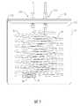
進一步而言,請參閱圖2及圖3所示,該露點測試腔體40的外殼41係一六角管,且該六角管具有相對的一第一端及一第二端,該六角管的第一端為該空氣輸入端44,而該六角管的第二端形成有一開口45,且該六角管的第二端周緣係沿其徑向向外延伸形成一底座46。在本較佳實施例中,該六角管係採用不鏽鋼管,且其內部係經過拋光處理。Further, as shown in FIGS. 2 and 3, the
由於該露點測試腔體40整體採用不繡鋼製作,且內部拋光使得氣體不易殘留表面達到穩定狀態,並具有多個容置孔43可同時連接多個待測露點傳感器60,且可接受轉接不同的牙規的使用。此外,該露點測試腔體40係採長條形設計,並利用冷空氣特性,讓上方的該空氣輸入端44導入的該恆溫氣體,向下方的開口45流動,以形成循環,達到氣體流動穩定。Because the dew
請參閱圖1所示,該露點傳感器的測試系統還包含有一空氣稀釋器80及一空氣混合器90。該空氣稀釋器80包含有一乾式流量控制單元81、一濕式流量控制單元82及一空氣混合單元83。Please refer to FIG. 1, the test system of the dew point sensor further includes an
該乾式流量控制單元81包含有一乾式輸入端及一乾式輸出端。該乾式輸入端連接該乾燥設備20的乾燥輸出端,接收該乾燥空氣,並產生一乾式空氣由該乾式輸出端輸出,且該乾式流量控制單元81控制該乾式空氣由該乾式輸出端輸出的流量。The dry
該濕式流量控制單元82包含有一濕式輸入端及一濕式輸出端。該濕式輸入端連接該乾燥設備的乾燥輸出端,接收該乾燥空氣,並產生一濕式空氣由該濕式輸出端輸出,且該濕式流量控制單元82控制該濕式空氣的濕度以及由該濕式輸出端輸出的流量。The wet
該空氣混合單元83包含有一第一輸入端、一第二輸入端及一輸出端。該空氣混合單元83的一第一輸入端連接至該乾式流量控制單元81的乾式輸出端,接收該乾式空氣,且該空氣混合單元83的第二輸入端連接至該濕式流量控制單元82的濕式輸出端,接收該濕式空氣,該空氣混合單元83進一步混合該乾式空氣及該濕式空氣後,產生一第一混合空氣由該輸出端輸出。The air mixing unit 83 includes a first input end, a second input end and an output end. A first input terminal of the air mixing unit 83 is connected to the dry output terminal of the dry
該空氣混合器90具有一第一輸入端、一第二輸入端及一混合空氣輸出端。該恆溫槽30的恆溫空氣輸出端係通過該空氣混合器90連接至該露點測試腔體40。該空氣混合器90的第一輸入端係連接至該恆溫槽30的恆溫空氣輸出端,接收該恆溫空氣,且該空氣混合器90的第二輸入端係連接至該空氣稀釋器80的空氣混合單元83的輸出端,接收該第一混合空氣,該空氣混合器90進一步混合該恆溫空氣及該第一混合空氣後,產生一第二混合空氣由該混合空氣輸出端輸出,而該空氣混合器90的混合空氣輸出端係連接至該露點測試腔體40的空氣輸入端44,輸出該第二混合空氣至該露點測試腔體40。The
本發明藉由該空氣稀釋器80裡面的該乾式流量控制單元81及該濕式流量控制單元82調節乾式氣體和濕式氣體的輸出量。且該乾式流量控制單元81及該濕式流量控制單元82分別輸出該乾式空氣及該濕式空氣,並依需求輸出不同比例的乾式空氣和濕式空氣後,通過該空氣混合單元83混合,再與恆溫槽30輸出的恆溫空氣通過該空氣混合氣90做混合,藉此控制改變該露點測試腔體40內的腔室的露點環境。如此一來,本發明便可透過該空氣稀釋器80營造出不同的露點環境,來驗證該些待測露點傳感器60在不同露點環境下感測到的露點溫度與該參考露點傳感器50感測到的露點溫度的差異,確認該些待測露點傳感器60的準確度,並可進一步根據差異對該些待測露點傳感器60進行較正。In the present invention, the output of dry gas and wet gas is adjusted by the dry
此外,該露點傳感器的測試系統進一步包含有一壓力傳感器100、一溫度傳感器110及一流量傳感器120。In addition, the test system of the dew point sensor further includes a
該壓力傳感器100設置於該露點測試腔體40的其中一容置孔43中,並檢測該露點測試腔體40的腔室42中的壓力,產生一壓力訊號。The
該溫度傳感器110設置於該露點測試腔體40的其中一容置孔43中,並檢測該露點測試腔體40的腔室42中的溫度,產生一溫度訊號。The
該流量傳感器120設置於該空氣混合器90的混合空氣輸出端與該露點測試腔體40的空氣輸入端44之間,並檢測該第二混合空氣流入該露點測試腔體40的流量,產生一流量訊號。The
該處理主機70進一步電連接該壓力傳感器100、該溫度傳感器110及該流量傳感器120,以接收並顯示該壓力訊號、該溫度訊號及該流量訊號。且該處理主機70進一步根據該壓力訊號判斷該露點測試腔體40的腔室42中的壓力是否在一壓力設定範圍內,藉此確認該露點測試腔體40的腔室42中的壓力一致性的穩定,有助於該露點測試腔體40的腔室42中的氣體平衡穩定。此外,當該處理主機70判斷該露點測試腔體40的腔室42中的壓力未在該壓力設定範圍內時,係產生一提醒訊號,藉此提醒使用者目前該露點測試腔體40的腔室42中的壓力在一異常狀態,供使用者參考,並提醒使用者前往處理。The
由於該露點測試腔體40的腔室42中的溫度的變化會影響相對濕度的改變,進而造成該露點測試腔體40的腔室42中的露點溫度的改變,特別是在露點溫度低的時候,該露點測試腔體40的腔室42中的溫度對露點溫度的影響會更多。因此該處理主機70還根據該溫度訊號判斷該露點測試腔體40的腔室42中的溫度是否在一溫度設定範圍內,藉此確認該露點測試腔體40的腔室42中的溫度一致性的穩定,有助於該露點測試腔體40的腔室42中的露點溫度平衡穩定。此外,當該處理主機70判斷該露點測試腔體40的腔室42中的溫度未在該溫度設定範圍內時,係產生一提醒訊號,藉此提醒使用者目前該露點測試腔體40的腔室42中的溫度在一異常狀態,供使用者參考,並提醒使用者前往處理。Since the temperature change in the
而該處理主機70進一步根據該流量訊號判斷該第二混合空氣流入該露點測試腔體40的流量是否在一流量設定範圍內,藉此確認流入該露點測試腔體40的腔室42中的第二混合空氣的氣體量,以確保該露點測試腔體40的腔室42中的氣體平衡穩定。此外,當該處理主機70判斷該第二混合空氣流入該露點測試腔體40的流量未在該流量設定範圍內時,係產生一提醒訊號,藉此提醒使用者目前該第二混合空氣流入該露點測試腔體40的流量在一異常狀態,供使用者參考,並提醒使用者前往處理。The
進一步而言,本發明的露點傳感器的測試系統還包含有一露點儀130。該露點儀130連接至該露點測試腔體40,並感測該露點測試腔體40的腔室42的露點溫度,以產生一露點訊號。且該處理主機70進一步電連接該露點儀130,以接收並顯示該露點訊號。Further, the test system of the dew point sensor of the present invention further includes a
由於該露點儀130具有較高的精密度,因此該露點儀130量測到的露點溫度相對而言係較為可靠的,故本發明進一步通過該露點儀130量測一個更具有參考價值的露點溫度作為標準,用於對該些待測露點傳感器60進行較正。Since the
以上所述僅是本發明的較佳實施例而已,並非對本發明做任何形式上的限制,雖然本發明已以較佳實施例揭露如上,然而並非用以限定本發明,任何熟悉本專業的技術人員,在不脫離本發明技術方案的範圍內,當可利用上述揭示的技術內容作出些許更動或修飾為等同變化的等效實施例,但凡是未脫離本發明技術方案的內容,依據本發明的技術實質對以上實施例所作的任何簡單修改、等同變化與修飾,均仍屬於本發明技術方案的範圍內。The above are only preferred embodiments of the present invention, and do not limit the present invention in any form. Although the present invention has been disclosed in the preferred embodiments as above, it is not intended to limit the present invention. Anyone who is familiar with this technology Personnel, within the scope of not departing from the technical solution of the present invention, when the technical contents disclosed above can be used to make some changes or modifications to equivalent embodiments of equivalent changes, but any content that does not depart from the technical solution of the present invention, according to the present invention Technical essence Any simple modifications, equivalent changes and modifications made to the above embodiments still fall within the scope of the technical solution of the present invention.
10:空壓機20:乾燥設備21:冷藏式乾燥機22:吸附式乾燥機23:化學式乾燥機30:恆溫槽31:桶狀殼體311:容至哭間312:開口32:頂蓋321:輸入孔322:輸出孔33:第一螺旋管34:第二螺旋管35:三通管36:止水閥40:露點測試腔體41:外殼42:腔室43:容置孔44:空氣輸入端45:開口46:底座50:參考露點傳感器60:待測露點傳感器70:處理主機80:空氣稀釋器81:乾式流量控制單元82:濕式流量控制單元83:空氣混合單元90:空氣混合器100:壓力傳感器110:溫度傳感器120:流量傳感器130:露點儀10: Air compressor 20: Drying equipment 21: Refrigerated dryer 22: Adsorption dryer 23: Chemical dryer 30: Constant temperature bath 31: Barrel-shaped housing 311: Capacity to crying room 312: Opening 32: Top cover 321 : Input hole 322: Output hole 33: First spiral tube 34: Second spiral tube 35: Three-way tube 36: Water stop valve 40: Dew point test chamber 41: Housing 42: Chamber 43: Receiving hole 44: Air Input 45: Opening 46: Base 50: Reference dew point sensor 60: Dew point sensor to be measured 70: Processing unit 80: Air diluter 81: Dry flow control unit 82: Wet flow control unit 83: Air mixing unit 90: Air mixing 100: Pressure sensor 110: Temperature sensor 120: Flow sensor 130: Dew point meter
圖1係本發明較佳實施例之系統方塊示意圖。 圖2係本發明較佳實施例之露點測試腔體的外觀示意圖。 圖3係本發明較佳實施例之露點測試腔體的側視示意圖。 圖4係本發明較佳實施例之恆溫槽的外觀示意圖。 圖5係本發明較佳實施例之恆溫槽的內部空間示意圖。FIG. 1 is a schematic block diagram of a system according to a preferred embodiment of the present invention. FIG. 2 is a schematic view of the appearance of the dew point test cavity of the preferred embodiment of the present invention. FIG. 3 is a schematic side view of the dew point test cavity of the preferred embodiment of the present invention. 4 is a schematic view of the appearance of a thermostatic bath in accordance with a preferred embodiment of the present invention. FIG. 5 is a schematic diagram of the internal space of the thermostatic bath according to the preferred embodiment of the present invention.
10:空壓機10: Air compressor
20:乾燥設備20: Drying equipment
21:冷藏式乾燥機21: Refrigerated dryer
22:吸附式乾燥機22: Adsorption dryer
23:化學式乾燥機23: Chemical dryer
30:恆溫槽30: Constant temperature bath
40:露點測試腔體40: Dew point test chamber
50:參考露點傳感器50: Reference dew point sensor
60:待測露點傳感器60: Dew point sensor to be measured
70:處理主機70: processing host
80:空氣稀釋器80: Air thinner
81:乾式流量控制單元81: Dry flow control unit
82:濕式流量控制單元82: Wet flow control unit
83:空氣混合單元83: Air mixing unit
90:空氣混合器90: air mixer
100:壓力傳感器100: pressure sensor
110:溫度傳感器110: temperature sensor
120:流量傳感器120: flow sensor
130:露點儀130: Dew point meter
Claims (10)
Translated fromChinesePriority Applications (2)
| Application Number | Priority Date | Filing Date | Title |
|---|---|---|---|
| TW107141212ATWI666435B (en) | 2018-11-20 | 2018-11-20 | Test system for dew point sensors |
| CN201910661602.4ACN111198205A (en) | 2018-11-20 | 2019-07-22 | Dew point sensor's test system |
Applications Claiming Priority (1)
| Application Number | Priority Date | Filing Date | Title |
|---|---|---|---|
| TW107141212ATWI666435B (en) | 2018-11-20 | 2018-11-20 | Test system for dew point sensors |
Publications (2)
| Publication Number | Publication Date |
|---|---|
| TWI666435B TWI666435B (en) | 2019-07-21 |
| TW202020427Atrue TW202020427A (en) | 2020-06-01 |
Family
ID=68049805
Family Applications (1)
| Application Number | Title | Priority Date | Filing Date |
|---|---|---|---|
| TW107141212ATWI666435B (en) | 2018-11-20 | 2018-11-20 | Test system for dew point sensors |
Country Status (2)
| Country | Link |
|---|---|
| CN (1) | CN111198205A (en) |
| TW (1) | TWI666435B (en) |
Families Citing this family (2)
| Publication number | Priority date | Publication date | Assignee | Title |
|---|---|---|---|---|
| TWI666435B (en)* | 2018-11-20 | 2019-07-21 | 宇田控制科技股份有限公司 | Test system for dew point sensors |
| CN114384119B (en)* | 2021-12-11 | 2024-08-27 | 首钢京唐钢铁联合有限责任公司 | Method and device for detecting dew point of compressed air in steel plant |
Family Cites Families (11)
| Publication number | Priority date | Publication date | Assignee | Title |
|---|---|---|---|---|
| CN101839790A (en)* | 2010-05-06 | 2010-09-22 | 上海哈德电气技术有限公司 | Intelligent on-line calibration system |
| KR20140031314A (en)* | 2011-06-13 | 2014-03-12 | 신닛테츠 수미킨 가가쿠 가부시키가이샤 | Sensor element, dew condensation sensor, humidity sensor, method for detecting dew condensation, and dew-point measurement device |
| CN103091366B (en)* | 2012-12-20 | 2015-02-18 | 同济大学 | Dewpoint calibration testing method used under complicated environments |
| JP2015227818A (en)* | 2014-05-30 | 2015-12-17 | 木村 光照 | Absolute humidity sensor capable of detecting dew point |
| CN104459043B (en)* | 2014-11-28 | 2016-02-03 | 苏州热工研究院有限公司 | The calibration steps of generator of nuclear power station hydrogen supply system moisture probe |
| CN204832086U (en)* | 2015-08-05 | 2015-12-02 | 无锡市计量检定测试中心 | Automatic calbiration system of dew -point hygrometer |
| CN105953836A (en)* | 2016-05-30 | 2016-09-21 | 国网河北省电力公司电力科学研究院 | A kind of inspection method of multi-parameter SF6 detection instrument |
| CN206676200U (en)* | 2016-11-15 | 2017-11-28 | 钟玲珑 | Source of the gas humidity freeze-day with constant temperature system |
| JP6767272B2 (en)* | 2017-01-30 | 2020-10-14 | アズビル株式会社 | Sensor calibration support device and method |
| CN107677699B (en)* | 2017-09-30 | 2020-07-07 | 中国南方电网有限责任公司超高压输电公司检修试验中心 | A method for detecting micro-water content in SF6 gas by mirror dew point method under plateau conditions |
| TWI666435B (en)* | 2018-11-20 | 2019-07-21 | 宇田控制科技股份有限公司 | Test system for dew point sensors |
- 2018
- 2018-11-20TWTW107141212Apatent/TWI666435B/enactive
- 2019
- 2019-07-22CNCN201910661602.4Apatent/CN111198205A/enactivePending
Also Published As
| Publication number | Publication date |
|---|---|
| CN111198205A (en) | 2020-05-26 |
| TWI666435B (en) | 2019-07-21 |
Similar Documents
| Publication | Publication Date | Title |
|---|---|---|
| CN101241093A (en) | A Gas Sensor Calibration and Reliability Test System | |
| CN201327427Y (en) | Temperature and humidity measurement calibrating device | |
| JP2008089575A5 (en) | ||
| TWI666435B (en) | Test system for dew point sensors | |
| CN114755263B (en) | Auxiliary device for detecting moisture and heat performance of fabric | |
| CN102998720A (en) | Method and device for calibrating dynamic response characteristic of sonde humidity by double flow method | |
| CN202939322U (en) | Device for calibrating humidity dynamic response characteristics of sonde with double-flow method | |
| CN112013928A (en) | Gas meter temperature/pressure adaptability integrated detection device and method | |
| CN107703021A (en) | A kind of portable air water content measurement apparatus | |
| CN110850040B (en) | Humidity meter inspection method and standard humidity generating device and method | |
| CN107422754A (en) | A kind of minimum gas current velocity controller and control method | |
| CN111665332B (en) | A kind of calibration device and calibration method of gas fire extinguishing agent concentration testing equipment | |
| CN211179761U (en) | Standard humidity generating device | |
| CN111175346A (en) | Water activity detection device, water activity detection tank and detection method thereof | |
| CN2932343Y (en) | Thermometer tester | |
| CN114646409A (en) | Dewar cold loss test tool and device | |
| CN207779949U (en) | Constant temperature atmosphere test chamber for film resistor hydrogen sensor calibration experiment | |
| CN105403850A (en) | Conductivity meter verifying apparatus | |
| CN207352016U (en) | The detection device of alcohol content tester | |
| CN208420223U (en) | A kind of hot and cold scale detection device | |
| CN208536911U (en) | A kind of gauge check application apparatus | |
| CN205246855U (en) | Conductivity meter verifying attachment | |
| CN220438281U (en) | Gas sensor's gas-sensitive characteristic testing arrangement | |
| CN223226068U (en) | Incubator gas consumption measuring system | |
| CN112525794A (en) | Portable automatic tester and testing method for surface air permeability of material |