TW202011907A - Dental articulator capable of fixed horizontal condyle and adjustable horizontal condyle - Google Patents
Dental articulator capable of fixed horizontal condyle and adjustable horizontal condyleDownload PDFInfo
- Publication number
- TW202011907A TW202011907ATW108115617ATW108115617ATW202011907ATW 202011907 ATW202011907 ATW 202011907ATW 108115617 ATW108115617 ATW 108115617ATW 108115617 ATW108115617 ATW 108115617ATW 202011907 ATW202011907 ATW 202011907A
- Authority
- TW
- Taiwan
- Prior art keywords
- temporomandibular joint
- angle
- pair
- adjustable
- fixed
- Prior art date
Links
- 210000001738temporomandibular jointAnatomy0.000claimsabstractdescription208
- 230000000712assemblyEffects0.000claimsabstractdescription11
- 238000000429assemblyMethods0.000claimsabstractdescription11
- 238000000034methodMethods0.000claimsdescription10
- 230000002123temporal effectEffects0.000claims3
- 238000005520cutting processMethods0.000description26
- 238000005266castingMethods0.000description11
- 238000005452bendingMethods0.000description5
- 210000001847jawAnatomy0.000description4
- 210000004373mandibleAnatomy0.000description3
- 230000001815facial effectEffects0.000description1
- 238000004519manufacturing processMethods0.000description1
- 210000002050maxillaAnatomy0.000description1
- 238000005259measurementMethods0.000description1
- 230000003278mimic effectEffects0.000description1
- 238000012986modificationMethods0.000description1
- 230000004048modificationEffects0.000description1
- 230000000149penetrating effectEffects0.000description1
- 125000006850spacer groupChemical group0.000description1
Images


Classifications
- A—HUMAN NECESSITIES
- A61—MEDICAL OR VETERINARY SCIENCE; HYGIENE
- A61C—DENTISTRY; APPARATUS OR METHODS FOR ORAL OR DENTAL HYGIENE
- A61C11/00—Dental articulators, i.e. for simulating movement of the temporo-mandibular joints; Articulation forms or mouldings
- A—HUMAN NECESSITIES
- A61—MEDICAL OR VETERINARY SCIENCE; HYGIENE
- A61C—DENTISTRY; APPARATUS OR METHODS FOR ORAL OR DENTAL HYGIENE
- A61C11/00—Dental articulators, i.e. for simulating movement of the temporo-mandibular joints; Articulation forms or mouldings
- A61C11/02—Dental articulators, i.e. for simulating movement of the temporo-mandibular joints; Articulation forms or mouldings characterised by the arrangement, location or type of the hinge means ; Articulators with pivots
- A61C11/022—Dental articulators, i.e. for simulating movement of the temporo-mandibular joints; Articulation forms or mouldings characterised by the arrangement, location or type of the hinge means ; Articulators with pivots with two adjustable pivoting points, e.g. Argon-type articulators
- A—HUMAN NECESSITIES
- A61—MEDICAL OR VETERINARY SCIENCE; HYGIENE
- A61C—DENTISTRY; APPARATUS OR METHODS FOR ORAL OR DENTAL HYGIENE
- A61C11/00—Dental articulators, i.e. for simulating movement of the temporo-mandibular joints; Articulation forms or mouldings
- A61C11/02—Dental articulators, i.e. for simulating movement of the temporo-mandibular joints; Articulation forms or mouldings characterised by the arrangement, location or type of the hinge means ; Articulators with pivots
- A—HUMAN NECESSITIES
- A61—MEDICAL OR VETERINARY SCIENCE; HYGIENE
- A61C—DENTISTRY; APPARATUS OR METHODS FOR ORAL OR DENTAL HYGIENE
- A61C11/00—Dental articulators, i.e. for simulating movement of the temporo-mandibular joints; Articulation forms or mouldings
- A61C11/06—Dental articulators, i.e. for simulating movement of the temporo-mandibular joints; Articulation forms or mouldings with incisal guide
- A—HUMAN NECESSITIES
- A61—MEDICAL OR VETERINARY SCIENCE; HYGIENE
- A61C—DENTISTRY; APPARATUS OR METHODS FOR ORAL OR DENTAL HYGIENE
- A61C11/00—Dental articulators, i.e. for simulating movement of the temporo-mandibular joints; Articulation forms or mouldings
- A61C11/08—Dental articulators, i.e. for simulating movement of the temporo-mandibular joints; Articulation forms or mouldings with means to secure dental casts to articulator
- A61C11/081—Dental articulators, i.e. for simulating movement of the temporo-mandibular joints; Articulation forms or mouldings with means to secure dental casts to articulator with adjusting means thereof
- A—HUMAN NECESSITIES
- A61—MEDICAL OR VETERINARY SCIENCE; HYGIENE
- A61C—DENTISTRY; APPARATUS OR METHODS FOR ORAL OR DENTAL HYGIENE
- A61C11/00—Dental articulators, i.e. for simulating movement of the temporo-mandibular joints; Articulation forms or mouldings
- A61C11/08—Dental articulators, i.e. for simulating movement of the temporo-mandibular joints; Articulation forms or mouldings with means to secure dental casts to articulator
- A61C11/087—Dental articulators, i.e. for simulating movement of the temporo-mandibular joints; Articulation forms or mouldings with means to secure dental casts to articulator using magnets
- A—HUMAN NECESSITIES
- A61—MEDICAL OR VETERINARY SCIENCE; HYGIENE
- A61C—DENTISTRY; APPARATUS OR METHODS FOR ORAL OR DENTAL HYGIENE
- A61C11/00—Dental articulators, i.e. for simulating movement of the temporo-mandibular joints; Articulation forms or mouldings
- A61C11/02—Dental articulators, i.e. for simulating movement of the temporo-mandibular joints; Articulation forms or mouldings characterised by the arrangement, location or type of the hinge means ; Articulators with pivots
- A61C11/025—Dental articulators, i.e. for simulating movement of the temporo-mandibular joints; Articulation forms or mouldings characterised by the arrangement, location or type of the hinge means ; Articulators with pivots with a pivotable lower part, i.e. mandibule motion simulator
Landscapes
- Health & Medical Sciences (AREA)
- Oral & Maxillofacial Surgery (AREA)
- Dentistry (AREA)
- Epidemiology (AREA)
- Life Sciences & Earth Sciences (AREA)
- Animal Behavior & Ethology (AREA)
- General Health & Medical Sciences (AREA)
- Public Health (AREA)
- Veterinary Medicine (AREA)
- Dental Prosthetics (AREA)
Abstract
Description
Translated fromChinese本發明係關於一種牙齒咬合架,該牙齒咬合架可以在固定水平髁角和可調水平髁角之間替換。The invention relates to a dental articulator, which can be replaced between a fixed horizontal condyle angle and an adjustable horizontal condyle angle.
咬合架是用於牙醫學的機械裝置,上頜骨(上部)和下頜骨(下部)牙齒的鑄件可與咬合架接合以模擬下頜骨運動並且重現上頜骨相對於下頜骨的記錄位置。咬合架有助於製造可拆卸口腔修復設備(假牙),固定的口腔修復學的恢復程序(牙冠術、橋接、鑲補術和鑲嵌術)和牙齒矯正設備。The articulator is a mechanical device used in dentistry. Castings of the teeth of the upper jaw (upper) and lower jaw (lower) can be engaged with the articulator to simulate movement of the mandible and reproduce the recorded position of the maxilla relative to the mandible. The articulator helps to make removable oral prosthetic devices (dentures), fixed prosthetic restoration procedures (crown, bridging, inlays and inlays) and orthodontic equipment.
一示例咬合架是一種由阿爾伯特哲伯原創發明的雙錐形咬合架。此咬合架和隨後研發相類似的非阿肯(non-arcon)類型咬合架,包括控制水平髁角的鉸接部分。在某些用途上,利用固定水平髁角可能是適宜的。對於其他目的而言,使用可調水平髁角可能是適宜的。先前技術中仍然需要一種可替換固定水平髁角或可調水平髁角的咬合架,使得使用者不需要分開使用不同的咬合架來實現每個需要的用途。An example articulator is a double-cone articulator originally invented by Albert Zheber. This articulator is similar to the non-arcon type articulator that was developed later, including an articulated part that controls the horizontal condyle angle. For some applications, it may be appropriate to use a fixed horizontal condyle angle. For other purposes, it may be appropriate to use adjustable horizontal condyle angles. In the prior art, there is still a need for an articulator that can replace a fixed horizontal condyle angle or an adjustable horizontal condyle angle, so that the user does not need to use different articulators separately to achieve each desired use.
本發明的目的在於提供一種牙齒咬合架,其係可替換為固定水平髁角或可調水平髁角。The object of the present invention is to provide a dental articulator, which can be replaced with a fixed horizontal condyle angle or an adjustable horizontal condyle angle.
本發明的上述和其他目的,以及相對於先前技術的優勢將通過下文描述和申請專利範圍的改進而實現,所述目的和優勢從下面的說明可以理解。The above and other objects of the present invention, as well as the advantages over the prior art, will be achieved by the following description and improvement of the scope of the patent application, which can be understood from the following description.
一種牙齒咬合架,包括下底座,具有從其延伸的兩個支撐臂。每個支撐臂具有帶開口的上端部。每個開口適於接收具有固定水平髁角的固定角度顳下頜關節組件或者接收具有可調水平髁角的可調整角度顳下頜關節組件。A dental articulator includes a lower base with two support arms extending therefrom. Each support arm has an upper end with an opening. Each opening is adapted to receive a fixed angle temporomandibular joint assembly with a fixed horizontal condyle angle or an adjustable angle temporomandibular joint assembly with an adjustable horizontal condyle angle.
一種牙齒咬合架套件,包括:咬合架底座,該底座具有下支架,該下支架具有從該支架延伸的兩個支撐臂。每個支撐臂具有帶開口的上端部。所述咬合架套件進一步包括一對具有固定水平髁角的固定角度顳下頜關節組件,其中該一對固定角度顳下頜關節組件各自具有一延伸部分,該延伸部分適於配合所述開口中相應的開口。作為可替代的選項,所述咬合架套件可進一步配備一對可調整角度顳下頜關節組件,該可調整角度顳下頜關節組件具有可調水平髁角,該一對可調整角度顳下頜關節組件各自具有一延伸部分,該一延伸部分適於配合到所述開口中相應的開口,其中,該可調整角度顳下頜關節組件可以是由使用者在一段時間後獲取,以便使用者能夠將該牙齒咬合架套件升級到包括一對固定顳下頜關節組件 和一對可調整顳下頜關節組件,此特徵並非所屬技術領域習知的。當獲取一對可調整顳下頜關節組件,所述固定角度顳下頜關節組件,可以與該可調整角度顳下頜關節組件在所述開口中互換,因應咬合架套件使用者需要固定水平髁角或可調整水平髁角。A dental articulator kit includes: an articulator base, the base has a lower bracket, and the lower bracket has two support arms extending from the bracket. Each support arm has an upper end with an opening. The articulator kit further includes a pair of fixed-angle temporomandibular joint assemblies with fixed horizontal condyle angles, wherein the pair of fixed-angle temporomandibular joint assemblies each have an extension portion that is adapted to fit a corresponding one of the openings Opening. As an alternative option, the articulator kit may be further equipped with a pair of adjustable-angle temporomandibular joint components that have adjustable horizontal condyle angles, and the pair of adjustable-angle temporomandibular joint components Has an extension portion adapted to fit into a corresponding opening in the opening, wherein the adjustable angle temporomandibular joint assembly may be acquired by the user after a period of time so that the user can bite the tooth The frame kit is upgraded to include a pair of fixed temporomandibular joint components and a pair of adjustable temporomandibular joint components. This feature is not known in the art. When a pair of adjustable temporomandibular joint components is obtained, the fixed-angle temporomandibular joint component can be interchanged with the adjustable-angle temporomandibular joint component in the opening, in response to the user's need to fix the horizontal condyle angle or Adjust the horizontal condyle angle.
一種調整牙齒咬合架的方法,包括如下步驟:提供具有下底座的牙齒咬合架,從該底座延伸兩個支撐臂,每個支撐臂具有帶開口的上端部,將一對具有固定水平髁角的顳下頜關節組件插入到所述開口中,將所述一對具有固定水平髁角的顳下頜關節組件從所述開口中拆卸,及將一對具有可調水平髁角的顳下頜關節組件插入到所述開口中。A method for adjusting a dental articulator includes the following steps: providing a dental articulator with a lower base, two support arms extending from the base, each support arm having an upper end with an opening, a pair of fixed horizontal condyle angles The temporomandibular joint assembly is inserted into the opening, the pair of temporomandibular joint assemblies with fixed horizontal condyle angle are removed from the opening, and the pair of temporomandibular joint assemblies with adjustable horizontal condyle angle are inserted into In the opening.
本發明的一個或者多個實施例具有產業利用性,提供了攜帶突出運動(protrusive movement)、凹陷運動(laterotrusive movement)和中間運動(mediotrusive movement)的能力,從而模製人類頜骨關節。One or more embodiments of the present invention are industrially applicable, providing the ability to carry protrusive movement, laterotrusive movement, and intermediate movement to mold human jaw joints.
因此很明顯如本文所述構造的咬合架達成了本發明的目的並且另外實質上改進了先前技術。It is therefore clear that the articulator constructed as described herein achieves the object of the present invention and further substantially improves the prior art.
10‧‧‧咬合架10‧‧‧ articulator
12‧‧‧下底座/下頜底座12‧‧‧Lower base/lower jaw base
14‧‧‧上底座/上頜底座14‧‧‧Upper base/upper jaw base
16‧‧‧支架16‧‧‧Bracket
18‧‧‧下牙科鑄件支架18‧‧‧ Lower dental casting bracket
20‧‧‧磁體20‧‧‧Magnet
22‧‧‧引切割銷22‧‧‧lead cutting pin
24‧‧‧插槽開口24‧‧‧slot opening
26‧‧‧切割銷組件26‧‧‧Cutting pin assembly
28‧‧‧支撐臂28‧‧‧support arm
29‧‧‧彎曲形狀29‧‧‧Curved shape
30‧‧‧開口30‧‧‧ opening
31‧‧‧彎曲形狀31‧‧‧Bending shape
32‧‧‧第一顳下頜關節(TMJ)組件(也可稱為固定TMJ組件或固定角度TMJ組件)32‧‧‧The first temporomandibular joint (TMJ) component (also called fixed TMJ component or fixed angle TMJ component)
33‧‧‧彎曲切口33‧‧‧Bent cut
34‧‧‧第二TMJ組件(也可稱為可調整TMJ組件或可調整角度TMJ組件)34‧‧‧Second TMJ component (also called adjustable TMJ component or adjustable angle TMJ component)
36‧‧‧延伸部分36‧‧‧Extended part
38‧‧‧延伸部分38‧‧‧Extended part
40‧‧‧孔40‧‧‧ hole
42‧‧‧緊固件42‧‧‧fastener
44‧‧‧O型環保持器44‧‧‧O-ring retainer
46‧‧‧凹槽46‧‧‧groove
48‧‧‧O型環48‧‧‧O-ring
50‧‧‧凹槽50‧‧‧groove
52‧‧‧軸52‧‧‧axis
62‧‧‧TMJ引導元件62‧‧‧TMJ guide element
64‧‧‧髁引導通道64‧‧‧Condylar guide channel
66‧‧‧雙錐形66‧‧‧Double cone
68‧‧‧中央直徑68‧‧‧Central diameter
70‧‧‧最深點70‧‧‧The deepest point
72‧‧‧TMJ中央鎖72‧‧‧ TMJ central lock
73‧‧‧底部邊緣73‧‧‧Bottom edge
74‧‧‧螺釘74‧‧‧screw
76‧‧‧凹槽76‧‧‧groove
78‧‧‧後退鎖開口78‧‧‧Back lock opening
80‧‧‧後退鎖80‧‧‧Back lock
82‧‧‧軸接收口82‧‧‧Axis receiving port
84‧‧‧鎖定螺釘孔84‧‧‧Lock screw hole
86‧‧‧鎖定螺釘86‧‧‧Locking screw
88‧‧‧通道88‧‧‧channel
90‧‧‧TMJ環90‧‧‧ TMJ ring
91‧‧‧表面91‧‧‧Surface
92‧‧‧通道92‧‧‧channel
94‧‧‧面弓適配器94‧‧‧Face Bow Adapter
96‧‧‧孔96‧‧‧ well
98‧‧‧螺釘98‧‧‧screw
100‧‧‧TMJ底座元件100‧‧‧TMJ base component
102‧‧‧水平髁角標識102‧‧‧Horizontal condyle angle sign
103‧‧‧開口103‧‧‧ opening
104‧‧‧TMJ引導元件104‧‧‧TMJ guide element
112‧‧‧指示線112‧‧‧Indicating line
114‧‧‧TMJ中心鎖114‧‧‧TMJ Center Lock
118‧‧‧面弓適配器118‧‧‧Face Bow Adapter
120‧‧‧TMJ環120‧‧‧ TMJ ring
122‧‧‧支架122‧‧‧Bracket
124‧‧‧軸底座124‧‧‧Shaft base
126‧‧‧通道126‧‧‧channel
130‧‧‧墊片130‧‧‧gasket
132‧‧‧軸蓋132‧‧‧Shaft cover
133‧‧‧上牙科鑄件支架133‧‧‧Upper dental casting bracket
134‧‧‧上彎曲元件134‧‧‧Upper bending element
136‧‧‧平面元件136‧‧‧Plane components
138‧‧‧磁體138‧‧‧Magnet
140‧‧‧引切割銷140‧‧‧lead cutting pin
141‧‧‧插槽開口141‧‧‧slot opening
142‧‧‧切割銷基部142‧‧‧cutting pin base
143‧‧‧切割銷上部143‧‧‧cutting pin upper part
144‧‧‧螺釘144‧‧‧screw
146‧‧‧中空較寬直徑部分146‧‧‧ Hollow wide diameter part
148‧‧‧測量部分148‧‧‧Measurement
150‧‧‧切割銷150‧‧‧Cutting pin
152‧‧‧切割盤152‧‧‧Cutting disc
154‧‧‧螺釘154‧‧‧screw
158‧‧‧螺釘158‧‧‧screw
160‧‧‧切割指示線160‧‧‧cutting indicator line
162‧‧‧面弓支架162‧‧‧Face bow bracket
164‧‧‧上水平支架164‧‧‧Upper horizontal bracket
166‧‧‧中間水平支架166‧‧‧Middle horizontal bracket
168‧‧‧下水平支架168‧‧‧Lower horizontal bracket
170‧‧‧垂直支架170‧‧‧Vertical bracket
172‧‧‧螺釘172‧‧‧screw
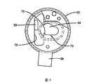
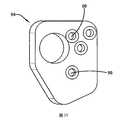
【圖1】係根據本發明原理的牙齒咬合架的立體視圖,具有可調整角度顳下頜關節(TMJ)組件。Fig. 1 is a perspective view of a dental articulator according to the principles of the present invention, with an adjustable angle temporomandibular joint (TMJ) assembly.
【圖2】係該咬合架的下底座部件的立體視圖。[Figure 2] A perspective view of the lower base part of the articulator.
【圖3】係固定角度顳下頜關節(TMJ)組件的立體視圖。[Figure 3] A perspective view of a fixed angle temporomandibular joint (TMJ) assembly.
【圖4】係圖3的TMJ組件的引導元件的側面視圖。[Fig. 4] A side view of the guide element of the TMJ assembly of Fig. 3.
【圖5】係圖4的引導元件的側面的面視圖。[Fig. 5] A side plan view of the guide element of Fig. 4.
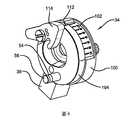
【圖6】係可調整角度顳下頜關節(TMJ)組件的立體視圖。[Figure 6] A perspective view of an adjustable-temporal mandibular joint (TMJ) assembly.
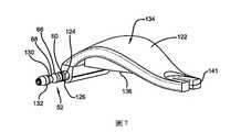
【圖7】係牙齒咬合架的上底座部件的立體視圖。[Fig. 7] A perspective view of the upper base part of the dental articulator.
【圖8】係圖7的上底座的仰視圖。[Fig. 8] A bottom view of the upper base of Fig. 7.
【圖9】係後退鎖的立體視圖。[Figure 9] A perspective view of the back lock.
【圖10】係後退鎖打開位置的側面視圖。[Figure 10] A side view of the open position of the back lock.
【圖11】係後退鎖關閉位置的側面視圖。[Figure 11] A side view of the closed position of the back lock.
【圖12】係TMJ環的立體視圖。[Figure 12] A perspective view of the TMJ ring.
【圖13】係面弓適配器的立體視圖。[Fig. 13] A perspective view of a tie bow adapter.
【圖14】係圖6的可調整角度TMJ的TMJ底座元件的立體視圖。[Fig. 14] A perspective view of the TMJ base member of the adjustable angle TMJ of Fig. 6.
【圖15】係圖6的可調整角度TMJ組件的引導元件的立體視圖。15 is a perspective view of the guide element of the adjustable angle TMJ assembly of FIG. 6.
【圖16】係圖15的引導元件的側面視圖。[Fig. 16] A side view of the guide element of Fig. 15.
【圖17】係切割銷組件的立體視圖。[Figure 17] A perspective view of the cutting pin assembly.
【圖18】係面弓支架的立體視圖。[Figure 18] A perspective view of a tie bow bracket.
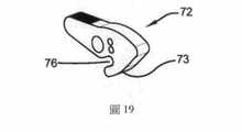
【圖19】係中央鎖的立體視圖。[Figure 19] A perspective view of the central lock.
【圖20】係圖19的中央鎖的側面視圖。[Fig. 20] A side view of the central lock of Fig. 19.
【圖21】係牙齒咬合架的局部俯視圖,表示咬合架一個側面上O型環設置於軸的凹槽中和O型環保持器。[Fig. 21] A partial top view of the dental articulator, showing that the O-ring on one side of the articulator is arranged in the groove of the shaft and the O-ring retainer.
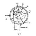
【圖22】係本發明原理的牙齒咬合架的立體視圖,具有固定角度顳下頜關節(TMJ)組件。[Fig. 22] A perspective view of a dental articulator according to the principles of the present invention, with a fixed angle temporomandibular joint (TMJ) assembly.
【圖23】係在鎖定位置中的TMJ中央鎖的局部立體視圖。[Figure 23] A partial perspective view of the TMJ central lock in the locked position.
圖式中以示例的方式展示根據本發明的概念的理想牙齒咬合架實施例,而非試圖展示可以體現本發明的所有各種形式和改裝,本發明由所請專利範圍所限定,而非由說明書的細節所限定。The drawings show by way of example the ideal dental articulator embodiment according to the concept of the invention, rather than trying to show all the various forms and modifications that can embody the invention. The invention is defined by the scope of the claimed patent, not by the specification Limited by the details.
根據本發明原理的牙齒咬合架總體上用元件符號10表示。牙齒咬合架10包括元件符號12表示的下底座及元件符號14表示的上底座,該下底座12亦可為下頜底座12,該上底座14亦可指上頜底座14。The tooth articulator according to the principles of the present invention is generally indicated by the
下底座12包括支架16,在該支架16上可安裝下牙科鑄件支架18。支架16包括磁體20和一個或多個引切割銷22,所述磁體20和所述一個或多個引切割銷22分別用於配對位於下牙科鑄件支架18的下部上對應的磁體和一個或多個引導孔。所屬技術領域中具有通常知識者已熟知,當牙科病人的下顎承載到顳下頜關節在其下顎的中央位置時,下牙科鑄件支架18可以設置在咬合架10鉸鏈軸的相同位置中。所屬技術領域中具有通常知識者已熟知,可以通過下顎鉸鏈軸定位器來確定顳下頜鉸鏈軸在該下顎的中央位置,例如鉸鏈弓或者面弓。The
在支架16的第一端,支架16包括用於接收切割銷組件26的插槽開口24,將如後進一步討論。在支架16的對置端部附近,支架16各側面的一部分向上延伸形成支撐臂28。支撐臂28彼此固定設置並且設置於該支架16。支撐臂28可以彼此分開設置於任何合適距離以便提供理想的髁間的距離。咬合架10的髁間距離是固定距離。At the first end of the
支撐臂28可以是利用適合於接收使用者的手的人體工程學設計。支撐臂28可以描述為一種具有從前向後方向形成的彎曲形狀29和從內到外方向形成的彎曲形狀31的抓握部分。彎曲形狀29也可以描述為具有前彎曲表面和後彎曲表面,所述彎曲形狀31也可以描述為具有內彎曲表面和外彎曲表面。因此,支撐臂28可以認為形成一種S型形狀。The
所述支撐臂28的後彎曲表面可以具有多個彎曲切口33,該切口33可以描述為手指凹槽33。手指凹槽33與彎曲形狀29和彎曲形狀31可以特別適於配合使用者的手的形狀,從而讓使用者能舒適和安全地握持。The rear curved surface of the
每個支撐臂28的上端包括用於接收相應的顳下頜關節(TMJ)組件32、34的開口30。特別是,TMJ組件32、34的對應延伸部分36、38配合在開口30中。延伸部分36、38的形狀和開口30的形狀應適當地配合以便將該延伸部分36、38完全固定在開口30中。延伸部分36、38和開口30的形狀可以是任何適合的形狀。在一個或者多個實施例中,延伸部分36、38和開口30可以是矩形的。The upper end of each
在每個支撐臂28的上端部附近,至少一個支撐臂28的內部側壁包括孔40,例如螺紋孔40,用於接收相應的可拆卸緊固件42,例如螺釘42。在一個或者多個實施例中,支撐臂28中只有其中一個包括孔40,使得單個螺釘可以用來將上頜底座14固定到位。在另一個實施例中,兩個支撐臂28均包括孔40。Near the upper end of each
正如本文將進一步描述,第一TMJ組件32(亦可稱為固定TMJ組件32或固定角度TMJ組件32)適於為牙齒咬合架10提供固定 水平髁角。As will be described further herein, the first TMJ component 32 (also referred to as the fixed
第二TMJ組件34(亦可稱為可調整TMJ組件34或可調整角度TMJ組件34)適於為咬合架10提供可調水平髁角。咬合架可通過將緊固件42插入到孔40中首先設有固定TMJ組件32。緊固件42的端部接觸固定TMJ組件32的延伸部分36,所述接觸包括將其部分插入到延伸部分36中,例如擰入到延伸部分36中以便將該固定TMJ組件32固定到位。在一個或者多個實施例中,緊固件42的平坦端部表面接觸延伸部分36的平坦表面以便將第一TMJ組件32固定到位。The second TMJ component 34 (also referred to as the
固定TMJ組件32包括O型環保持器44,該O型環保持器44可以部分擰入連接到固定TMJ組件32中。O型環保持器44從固定TMJ組件32內表面延伸並且包括凹槽46,用於保持O型環48的一部分在O型保持器中。如圖21所示,O型環48的一部分亦設置在上底座14的軸52中的凹槽50中。O型環48設置在相應的凹槽50中以保持上底座14在單一組件中,使得其部分可以作為單一組件從下底座12加入和拆卸。The fixed
當使用者需要從固定TMJ組件32替換成可調整TMJ組件34時,每個緊固件42則被拆卸而至不接觸相應的延伸部分36,使得延伸部分36可以從該開口30中移除。然後所述O型環48從每個相應凹槽中拆卸,使得固定TMJ組件32通過不再接合所述軸52並能夠被移除。然後O型環48以相同的固定方式重設置在所述軸52的各個相應凹槽50和可調整TMJ組件34的每個O型環保持器56的凹槽54中。類似於固定TMJ組件32,可調整TMJ組件34的每個O型環保持器56從其內表面延伸。 O型環56可以部分擰入連接到可調整TMJ組件34中。同樣地,O型環48設置在相應凹槽中以保持上底座14在單一組件中,使得其部分可以作為單一組件從該下底座12加入或者拆卸。然後,可調整TMJ組件34,特別是可調整TMJ組件34的每個延伸部分38可以設置在每個開口30中。由可調整TMJ組件34切換到固定TMJ組件32的調整應被理解為以本文所述從固定TMJ組件32切換到可調整TMJ組件34的類似方式達成。When the user needs to replace the fixed
如上所述,固定TMJ組件32包括延伸部分36,該延伸部分36是從TMJ引導元件62向下延伸。根據所屬技術領域在使用咬合架的通常知識,TMJ引導元件62包括髁引導通道64和多個定位咬合架10的螺紋孔。髁引導通道64在咬合架10的初始位置中接收軸52的雙錐部分66,特別是雙錐形部分66的最小直徑部分或中心直徑部分68。As mentioned above, the fixed
如先前技術已知的,為了模似最大化交叉牙齒(intercuspidation),該雙錐形66的中央直徑68設置在髁引導通道64的最深點70中。雙錐形66和軸52繼而能夠以TMJ中央鎖72就髁引導通道64中鎖定到位。圖23展示出TMJ中央鎖72鎖定狀況,TMJ中央鎖72的鎖定表面73正接觸軸52。TMJ中央鎖72可以向後或者向前移動以便從軸52上解除鎖定表面73,從而將TMJ中央鎖72移至解鎖位置。TMJ中央鎖72可以包括一個或者多個貫通螺釘74以使保持TMJ中央鎖72的相對位置,但是該一個或者多個螺釘74並不會防礙TMJ中央鎖72從鎖定狀況移動至解鎖位置。正如先前技術已知,球塞可以用在TMJ中央鎖72和TMJ引導元件62之間。凹槽76可以在TMJ中央鎖72中形成以便用作固定「夾」或者「彈簧」。As is known in the prior art, in order to mimic maximizing intercuspidation, the
當TMJ中心鎖72處於解鎖位置時,雙錐66的中心直徑68能夠通過沿髁突引導通道64的底部邊緣73移動而前進和後退(即,中心突出和中心後退)。如先前技術所知,可通過以橫向方式移動軸52來模擬瞬間側移。應理解的是咬合架10因此允許3維倍奈特運動(Bennett movement)。所屬技術領域中具有通常知識者將明白咬合架10為非阿肯(non-arcon)的咬合架,亦因此可理解到某些運動是如何與模型化相關聯的。When the TMJ
TMJ引導元件62的髁引導通道64進一步包括帶有後退鎖80的後退鎖開口78。後退鎖80通常塑造成可與後退鎖開口78配合並且包括軸接收口82和用於接收鎖定螺釘86的鎖定螺釘孔84。後退鎖80可在後退鎖開口78中的打開位置(圖10)和關閉位置(圖11)之間運動,所述打開位置指軸接收口82能夠接收軸52,而關閉位置指軸接收口82被阻止接收軸52。通過鬆開鎖定螺釘86來讓後退鎖80行走便可使後退鎖80在打開位置和關閉位置之間移動。當在理想的位置時,將鎖定螺釘86在通道88中擰緊便可將後退鎖80固定到位。The
固定TMJ組件32可以進一步包括TMJ環90(圖12),其包括通道92用於如上述描述般來移動後退鎖80。TMJ環90可以設置成可提供平坦表面91以使得面弓適配器94(圖13)能夠穩固在TMJ環90的外面。所屬技術領域中具有通常知識者已熟知,面弓可以用來記錄面部和上下頜的尺寸。接著,面弓能通過面弓轉移將此等記錄轉移到咬合架10。面弓適配器94可包括多個面弓轉移開口或孔96來接收不同品牌和型號的面弓。面弓適配器94可由銷和螺釘98穩固在軸52。所述銷可以接碰軸 52的外部分。The fixed
其於TMJ引導元件62相對下底座12的固定位置,固定TMJ組件32適於為咬合架10提供固定水平髁角。該固定水平髁角可以為任何合適的角度。在一個或者多個實施例中,該固定水平髁角可以是30度。At a fixed position of the
可調整TMJ組件34具有如固定TMJ組件32的類似整體結構,儘管可調整TMJ組件34為咬合架10提供可調整水平髁角。如上所述,可調整TMJ組件34包括延伸部分38,該延伸部分38從TMJ底座元件100向下延伸。如圖6所示,TMJ底座元件100包括用於讀取當前的水平髁角標識102。TMJ底座元件100具有與可調整TMJ引導元件104配合的開口103。根據所屬技術領域之先前技術來使用咬合架,TMJ引導元件104包括髁突導通道106和多個用於定位咬合架10的螺釘孔。The
當可調整TMJ組件34與咬合架10一併使用時,TMJ引導元件104可相對於TMJ底座元件100作部分旋轉。所述部分旋轉使得該可調整TMJ組件34為咬合架10提供可調整水平髁角。鎖定螺釘(未圖示)可以穿過TMJ底座元件100定位使得該鎖定螺釘可以接觸TMJ引導元件104以便將該鎖定螺釘固定到位。該鎖定螺釘可以在鬆開的或者解鎖位置中以便旋轉TMJ引導元件104。當達到所需的水平髁角時,該鎖定螺釘置於擰緊或者鎖定位置便可將TMJ引導元件104固定到位。TMJ引導元件104可以包括與標識102對應的指示線112,以便向使用者指示出水平髁角。根據該TMJ引導元件104相對下底座12的可調整位置,可調整TMJ組件34適於為咬合架10提供可調水平髁角。該可調水平髁角的範圍可以 是任何適合的範圍。在一個或者多個實施例中,該可調水平髁角可以是從0度以上至70度以下。When the
除了如上所述之外,應當理解的是TMJ引導元件104與TMJ引導元件62是類似的,並因此容許咬合架10以類似的方式操作。例如,類似的元件符號,如同用於標示髁引導通道64,亦是用於標示髁引導通道106的部件(例如,圖15)。可調整TMJ組件34還包括TMJ中心鎖114、後退鎖80、面弓適配器118及TMJ環120,這些部件在結構和操作上與上述用於固定TMJ組件32的相應部件相似。Except as described above, it should be understood that the
儘管在固定TMJ組件32和可調整TMJ組件34的某些元件(例如TMJ中央鎖72和TMJ中央鎖114)用上了不同的元件符號,但應當理解為在一個或者多個實施例中,此等元件在TMJ組件32和可調整TMJ組件34是類似的,並且當在固定TMJ組件32和可調整TMJ組件34之間替換時,是可以從TMJ組件32中卸下並且套用在可調整TMJ組件34,反之亦然。然而,每個固定TMJ組件32和可調整TMJ組件34可以設有它們各自的匹配元件,以使在固定TMJ組件32和可調整TMJ組件34之間的替換可更快速和有效。Although certain elements (such as TMJ
如上述所記載,固定TMJ組件32和可調整TMJ組件34的使用中的元件,與軸52配合以便移動上頜底座14的支架122。在支架122的第一端,軸52可包括部分定位在通道126(也可以描述為孔)的軸底座124。如上所述,軸底座124包括用於將O型環定位的凹槽50。為便於生產,軸底座可在每端設有較小直徑部分以便承載相應墊片130和雙錐66。軸蓋子132可以設置在軸52的每端以便將軸52的元件固定到位。軸 蓋132的外表面可為被切掉一部分以便接收用於固定面弓適配器的銷。As described above, the elements in use of the fixed
軸52相對地固定在支架122使得支架122可以與作為鉸接軸與軸52一同打開和關閉(圖1表示支架的關閉位置)。此固定設置可以由小銷或者任何其他合適的技術提供。支架122構成上底座14的構件,在支架122上可以安裝上牙科鑄件支架133。支架122可以包括上彎曲元件134,其平面元件136設置在上彎曲元件134的凹陷部分中。The
平面元件136具有面向下底座12的平坦表面,包括磁體138和一個或者多個引切割銷140,分別用於配對在上牙科鑄件支架133上部相應的磁體及一個或者多個的引導孔。如所屬技術領域習知的,當牙科病人的下顎承載到顳下頜關節在其下顎的中央位置時,上牙科鑄件支架133可以設置在與咬合架10鉸接軸的相同位置上。The
在與通道126相對的支撐122的端部處設有插槽開口141以接收切割銷組件26。具體地,插槽開口141接收切割銷基部142的上部143。該上部143可包括螺釘的螺紋開口,用於接收螺釘144以便將切割銷組件26固定到位。切割銷底座142進一步包括中空較寬直徑部分146和用於幫助使用者設定高度的測量部分148。中空較寬直徑部分146接收切割銷150的端部和另一部分,其中切割銷150的另一端設置在切割盤152處。切割盤152可由螺釘154穿過插槽開口24固定到位。切割盤152可具有凹陷上表面,在一個或者多個實施例中,該凹陷上表面可以成20°的角度。A
通過穿入中空較寬直徑部分146和測量部分148中,切割銷150可作垂直調整。中空較寬直徑部分146包括用於接收螺釘158的鎖 定孔以便鎖定銷150的位置。當螺釘158鬆開時,銷150可以垂直調整。當處於所需位置時,將螺釘158擰緊在中空較寬直徑部分146內的開口中,以將銷150固定到位。銷150可以包括用於接收切割指示線160的孔。切割指示線的形狀及應用為所屬技術領域中具有通常知識者所熟知。By penetrating into the hollow
面弓支架162可以與切割銷組件26一起使用。面弓支架162包括與中空較寬直徑部分146一同定位的上水平支架164,中間水平支架166以及下水平支架168,其中,銷150定位於貫穿中間水平支架166和銷150尖端設置在下水平支架168中。垂直支架170連接上水平支架164,中間水平支架166和下水平支架168。具有中間水平支架166的螺釘172可以用於調整面弓支架162。面弓支架162的操作是所屬技術領域中具有通常知識者所熟知的。
應該理解,某些部件在圖式中表示為左部件或右部件,並且用於另一對TMJ組件的相應部件將是所表示部件的鏡像。It should be understood that certain components are represented as left or right components in the drawings, and the corresponding components for another pair of TMJ assemblies will be mirror images of the components represented.
一個或者多個實施例包括具有本文所述咬合架10的咬合架套件,其中提供給使用者的套件包括咬合架10,其僅具有一對固定TMJ組件(例如固定TMJ組件32)。換句話說,此等實施例可為沒有可調整TMJ組件對(例如可調整TMJ組件34)的咬合架套件。因此,使用者可首先獲取僅具有固定TMJ組件對的咬合架10的套件,並且使用僅具有固定TMJ組件對的咬合架10。在一段時間之後,使用者可以藉由獲得可調整TMJ組件以升級該咬合架10,使得使用者的套件將包括固定TMJ組件對和可調整TMJ組件對。一段時間可以是任何合適長度的時間,例如至少一周、至少一個月或者至少一年。此等實施例可以提供以下優點:允許使 用者花費較低的初始費用來獲取包括僅具有固定TMJ組件的套件(即,對比同樣包括固定TMJ組件對和可調整TMJ組件對的套件為較低),其後以花費額外費用以獲得可調整TMJ組件對,而不是購買另一個全新的咬合架套件。One or more embodiments include a bite frame kit having a
一個或多個實施例包括具有本文所述的咬合架10的咬合架套件,其中提供給使用者的套件包括具有固定TMJ組件對(例如固定的TMJ組件32)和可調整TMJ組件對(例如可調整TMJ組件34)的咬合架10。One or more embodiments include an articulator kit with an
在某些實施例中,上述的套件不具有面弓適配器94。在此等實施例中,面弓適配器94可以由使用者於該套件分開獲得。In some embodiments, the kit described above does not have a
本發明的一個或者多個實施例具有產業利用性,提供了攜帶突出運動(protrusive movement)、凹陷運動(laterotrusive movement)和中間運動(mediotrusive movement)的能力,從而模製人類頜骨關節。One or more embodiments of the present invention are industrially applicable, providing the ability to carry protrusive movement, laterotrusive movement, and intermediate movement to mold human jaw joints.
因此很明顯如本文所述構造的咬合架達成了本發明的目的並且另外實質上改進了先前技術。It is therefore clear that the articulator constructed as described herein achieves the object of the present invention and further substantially improves the prior art.
10‧‧‧咬合架10‧‧‧ articulator
12‧‧‧下底座/下頜底座12‧‧‧Lower base/lower jaw base
14‧‧‧上底座/上頜底座14‧‧‧Upper base/upper jaw base
16‧‧‧支架16‧‧‧Bracket
18‧‧‧下牙科鑄件支架18‧‧‧ Lower dental casting bracket
26‧‧‧切割銷組件26‧‧‧Cutting pin assembly
28‧‧‧支撐臂28‧‧‧support arm
29‧‧‧彎曲形狀29‧‧‧Curved shape
31‧‧‧彎曲形狀31‧‧‧Bending shape
33‧‧‧彎曲切口33‧‧‧Bent cut
34‧‧‧第二顳下頜關節(TMJ)組件(也可稱為可調整TMJ組件或可調整角度TMJ組件)34‧‧‧Second temporomandibular joint (TMJ) component (also called adjustable TMJ component or adjustable angle TMJ component)
42‧‧‧緊固件42‧‧‧fastener
72‧‧‧TMJ中央鎖72‧‧‧ TMJ central lock
98‧‧‧螺釘98‧‧‧screw
118‧‧‧面弓適配器118‧‧‧Face Bow Adapter
120‧‧‧TMJ環120‧‧‧ TMJ ring
122‧‧‧支架122‧‧‧Bracket
124‧‧‧軸底座124‧‧‧Shaft base
126‧‧‧通道126‧‧‧channel
130‧‧‧墊片130‧‧‧gasket
133‧‧‧上牙科鑄件支架133‧‧‧Upper dental casting bracket
162‧‧‧面弓支架162‧‧‧Face bow bracket
Claims (17)
Translated fromChineseApplications Claiming Priority (2)
| Application Number | Priority Date | Filing Date | Title |
|---|---|---|---|
| US16/136,969US20200093580A1 (en) | 2018-09-20 | 2018-09-20 | Dental articulator capable of fixed horizontal condyle and adjustable horizontal condyle |
| US16/136,969 | 2018-09-20 |
Publications (2)
| Publication Number | Publication Date |
|---|---|
| TW202011907Atrue TW202011907A (en) | 2020-04-01 |
| TWI720474B TWI720474B (en) | 2021-03-01 |
Family
ID=69855700
Family Applications (1)
| Application Number | Title | Priority Date | Filing Date |
|---|---|---|---|
| TW108115617ATWI720474B (en) | 2018-09-20 | 2019-05-06 | Dental articulator capable of fixed horizontal condyle and adjustable horizontal condyle and a method of adjusting the dental articulator |
Country Status (3)
| Country | Link |
|---|---|
| US (1) | US20200093580A1 (en) |
| CN (2) | CN110916830A (en) |
| TW (1) | TWI720474B (en) |
Families Citing this family (3)
| Publication number | Priority date | Publication date | Assignee | Title |
|---|---|---|---|---|
| US20200093580A1 (en)* | 2018-09-20 | 2020-03-26 | Tesco Dental (Hong Kong) Limited | Dental articulator capable of fixed horizontal condyle and adjustable horizontal condyle |
| USD902411S1 (en)* | 2018-10-01 | 2020-11-17 | National Dentex, Llc | Interface for dental model articulator adaptor |
| ES2891794B2 (en)* | 2020-07-24 | 2022-06-15 | Trimag System S L | DEVICE FOR MAKING, DUPLICATING AND FIXING DENTAL MODELS IN ARTICULATOR |
Family Cites Families (7)
| Publication number | Priority date | Publication date | Assignee | Title |
|---|---|---|---|---|
| US2474488A (en)* | 1946-07-01 | 1949-06-28 | Wayne W Moore | Dental articulator |
| DE4211004C2 (en)* | 1992-04-02 | 1996-08-14 | Kaltenbach & Voigt | Dental articulator and dental articulator system |
| JP3555829B2 (en)* | 1997-11-07 | 2004-08-18 | 有限会社エー.ジー.オー | Articulator |
| CN201098209Y (en)* | 2007-08-15 | 2008-08-13 | 赵学峰 | Denture palate |
| TWI382830B (en)* | 2008-11-27 | 2013-01-21 | Phillip P Ho | Method of using denture reference device for dentistry |
| CN201350136Y (en)* | 2008-12-31 | 2009-11-25 | 浙江工业大学 | dental articulator |
| US20200093580A1 (en)* | 2018-09-20 | 2020-03-26 | Tesco Dental (Hong Kong) Limited | Dental articulator capable of fixed horizontal condyle and adjustable horizontal condyle |
- 2018
- 2018-09-20USUS16/136,969patent/US20200093580A1/ennot_activeAbandoned
- 2019
- 2019-05-06TWTW108115617Apatent/TWI720474B/enactive
- 2019-07-02CNCN201910588247.2Apatent/CN110916830A/enactivePending
- 2019-07-02CNCN201921013225.5Upatent/CN211796971U/enactiveActive
Also Published As
| Publication number | Publication date |
|---|---|
| TWI720474B (en) | 2021-03-01 |
| CN211796971U (en) | 2020-10-30 |
| US20200093580A1 (en) | 2020-03-26 |
| CN110916830A (en) | 2020-03-27 |
Similar Documents
| Publication | Publication Date | Title |
|---|---|---|
| US4634377A (en) | Device for aligning artificial teeth and crowns | |
| US6582931B1 (en) | Dento-facial analyzer | |
| JP3306593B2 (en) | Facebow with jaw articulator and occlusal fork column | |
| US11259907B2 (en) | Device for recording centric jaw relation and orientation jaw relation simultaneously | |
| US5090901A (en) | Face bow and adjustable occlusal fork | |
| US20190290411A1 (en) | Dental measurement device and prosthetic manufacturing system | |
| TWI720474B (en) | Dental articulator capable of fixed horizontal condyle and adjustable horizontal condyle and a method of adjusting the dental articulator | |
| US3913230A (en) | Dental setup guide and diagnostic instrument | |
| BRPI0904212A2 (en) | fast and simple positioning and repositioning equipment of the arches without the use of plaster, which allows the simulation of the mandibular movement and its method of operation. | |
| WO2016182214A1 (en) | Artificial tooth articulator | |
| Hickey et al. | A new articulator for use in teaching and general dentistry | |
| US20060210944A1 (en) | Dental modeling and articulating system and method | |
| JP3181517U (en) | Byte fork | |
| US4368041A (en) | Dental simulator and method for recording jaw movements | |
| US10492895B1 (en) | Facebow with double bite forks | |
| US20060216667A1 (en) | Dental modeling and articulating system and method | |
| JP2866084B2 (en) | Completely reproducible articulator | |
| US7128574B2 (en) | Dental alignment instrument | |
| JP4342888B2 (en) | Pupil line display method | |
| KR101686844B1 (en) | Articulator | |
| US10350038B1 (en) | Dental articulator system and apparatus | |
| WO2006091982A2 (en) | Dental modeling and articulating system and method | |
| JP4190842B2 (en) | Dental articulator | |
| JP2003220079A (en) | Apparatus and method for analyzing articulation and reference marker | |
| US9820832B2 (en) | Vertically adjustable rotational stabilizer for a disposable articulator |