TW202011366A - Multi-link hinge and electronic device in which the torsion plate may be rotated synchronously by the synchronizing link - Google Patents
Multi-link hinge and electronic device in which the torsion plate may be rotated synchronously by the synchronizing linkDownload PDFInfo
- Publication number
- TW202011366A TW202011366ATW107131344ATW107131344ATW202011366ATW 202011366 ATW202011366 ATW 202011366ATW 107131344 ATW107131344 ATW 107131344ATW 107131344 ATW107131344 ATW 107131344ATW 202011366 ATW202011366 ATW 202011366A
- Authority
- TW
- Taiwan
- Prior art keywords
- link
- torsion
- links
- friction
- pivoting
- Prior art date
Links
Images


Classifications
- H—ELECTRICITY
- H04—ELECTRIC COMMUNICATION TECHNIQUE
- H04M—TELEPHONIC COMMUNICATION
- H04M1/00—Substation equipment, e.g. for use by subscribers
- H04M1/02—Constructional features of telephone sets
- H04M1/0202—Portable telephone sets, e.g. cordless phones, mobile phones or bar type handsets
- H04M1/0206—Portable telephones comprising a plurality of mechanically joined movable body parts, e.g. hinged housings
- H04M1/0208—Portable telephones comprising a plurality of mechanically joined movable body parts, e.g. hinged housings characterized by the relative motions of the body parts
- H04M1/0214—Foldable telephones, i.e. with body parts pivoting to an open position around an axis parallel to the plane they define in closed position
- H04M1/0216—Foldable in one direction, i.e. using a one degree of freedom hinge
- H04M1/022—The hinge comprising two parallel pivoting axes
- E—FIXED CONSTRUCTIONS
- E05—LOCKS; KEYS; WINDOW OR DOOR FITTINGS; SAFES
- E05D—HINGES OR SUSPENSION DEVICES FOR DOORS, WINDOWS OR WINGS
- E05D11/00—Additional features or accessories of hinges
- E05D11/08—Friction devices between relatively-movable hinge parts
- E05D11/087—Friction devices between relatively-movable hinge parts with substantially axial friction, e.g. friction disks
- E—FIXED CONSTRUCTIONS
- E05—LOCKS; KEYS; WINDOW OR DOOR FITTINGS; SAFES
- E05D—HINGES OR SUSPENSION DEVICES FOR DOORS, WINDOWS OR WINGS
- E05D7/00—Hinges or pivots of special construction
- G—PHYSICS
- G06—COMPUTING OR CALCULATING; COUNTING
- G06F—ELECTRIC DIGITAL DATA PROCESSING
- G06F1/00—Details not covered by groups G06F3/00 - G06F13/00 and G06F21/00
- G06F1/16—Constructional details or arrangements
- G06F1/1613—Constructional details or arrangements for portable computers
- G06F1/1615—Constructional details or arrangements for portable computers with several enclosures having relative motions, each enclosure supporting at least one I/O or computing function
- G06F1/1616—Constructional details or arrangements for portable computers with several enclosures having relative motions, each enclosure supporting at least one I/O or computing function with folding flat displays, e.g. laptop computers or notebooks having a clamshell configuration, with body parts pivoting to an open position around an axis parallel to the plane they define in closed position
- G—PHYSICS
- G06—COMPUTING OR CALCULATING; COUNTING
- G06F—ELECTRIC DIGITAL DATA PROCESSING
- G06F1/00—Details not covered by groups G06F3/00 - G06F13/00 and G06F21/00
- G06F1/16—Constructional details or arrangements
- G06F1/1613—Constructional details or arrangements for portable computers
- G06F1/1633—Constructional details or arrangements of portable computers not specific to the type of enclosures covered by groups G06F1/1615 - G06F1/1626
- G06F1/1637—Details related to the display arrangement, including those related to the mounting of the display in the housing
- G06F1/1652—Details related to the display arrangement, including those related to the mounting of the display in the housing the display being flexible, e.g. mimicking a sheet of paper, or rollable
- G—PHYSICS
- G06—COMPUTING OR CALCULATING; COUNTING
- G06F—ELECTRIC DIGITAL DATA PROCESSING
- G06F1/00—Details not covered by groups G06F3/00 - G06F13/00 and G06F21/00
- G06F1/16—Constructional details or arrangements
- G06F1/1613—Constructional details or arrangements for portable computers
- G06F1/1633—Constructional details or arrangements of portable computers not specific to the type of enclosures covered by groups G06F1/1615 - G06F1/1626
- G06F1/1675—Miscellaneous details related to the relative movement between the different enclosures or enclosure parts
- G06F1/1679—Miscellaneous details related to the relative movement between the different enclosures or enclosure parts for locking or maintaining the movable parts of the enclosure in a fixed position, e.g. latching mechanism at the edge of the display in a laptop or for the screen protective cover of a PDA
- G—PHYSICS
- G06—COMPUTING OR CALCULATING; COUNTING
- G06F—ELECTRIC DIGITAL DATA PROCESSING
- G06F1/00—Details not covered by groups G06F3/00 - G06F13/00 and G06F21/00
- G06F1/16—Constructional details or arrangements
- G06F1/1613—Constructional details or arrangements for portable computers
- G06F1/1633—Constructional details or arrangements of portable computers not specific to the type of enclosures covered by groups G06F1/1615 - G06F1/1626
- G06F1/1675—Miscellaneous details related to the relative movement between the different enclosures or enclosure parts
- G06F1/1681—Details related solely to hinges
- H—ELECTRICITY
- H04—ELECTRIC COMMUNICATION TECHNIQUE
- H04M—TELEPHONIC COMMUNICATION
- H04M1/00—Substation equipment, e.g. for use by subscribers
- H04M1/02—Constructional features of telephone sets
- H04M1/0202—Portable telephone sets, e.g. cordless phones, mobile phones or bar type handsets
- H04M1/026—Details of the structure or mounting of specific components
- H04M1/0266—Details of the structure or mounting of specific components for a display module assembly
- H04M1/0268—Details of the structure or mounting of specific components for a display module assembly including a flexible display panel
- E—FIXED CONSTRUCTIONS
- E05—LOCKS; KEYS; WINDOW OR DOOR FITTINGS; SAFES
- E05D—HINGES OR SUSPENSION DEVICES FOR DOORS, WINDOWS OR WINGS
- E05D3/00—Hinges with pins
- E05D3/06—Hinges with pins with two or more pins
- E—FIXED CONSTRUCTIONS
- E05—LOCKS; KEYS; WINDOW OR DOOR FITTINGS; SAFES
- E05D—HINGES OR SUSPENSION DEVICES FOR DOORS, WINDOWS OR WINGS
- E05D3/00—Hinges with pins
- E05D3/06—Hinges with pins with two or more pins
- E05D3/12—Hinges with pins with two or more pins with two parallel pins and one arm
- E05D3/122—Gear hinges
- E—FIXED CONSTRUCTIONS
- E05—LOCKS; KEYS; WINDOW OR DOOR FITTINGS; SAFES
- E05Y—INDEXING SCHEME ASSOCIATED WITH SUBCLASSES E05D AND E05F, RELATING TO CONSTRUCTION ELEMENTS, ELECTRIC CONTROL, POWER SUPPLY, POWER SIGNAL OR TRANSMISSION, USER INTERFACES, MOUNTING OR COUPLING, DETAILS, ACCESSORIES, AUXILIARY OPERATIONS NOT OTHERWISE PROVIDED FOR, APPLICATION THEREOF
- E05Y2999/00—Subject-matter not otherwise provided for in this subclass
Landscapes
- Engineering & Computer Science (AREA)
- Computer Hardware Design (AREA)
- Theoretical Computer Science (AREA)
- Physics & Mathematics (AREA)
- Human Computer Interaction (AREA)
- General Engineering & Computer Science (AREA)
- General Physics & Mathematics (AREA)
- Signal Processing (AREA)
- Mechanical Engineering (AREA)
- Mathematical Physics (AREA)
- Telephone Set Structure (AREA)
- Pivots And Pivotal Connections (AREA)
Abstract
Description
Translated fromChinese本發明是有關於一種鉸鏈,特別是指一種多連桿式鉸鏈及電子裝置。The invention relates to a hinge, in particular to a multi-link hinge and an electronic device.
消費性電子產品已成為人們生活中不可或缺的一部分,且隨著物聯網的時代來臨,人們幾乎可以依靠一隻智慧型手機或平板電腦完成一日所需。手機與平板電腦的螢幕也為了能顯示出更多訊息,及提高使用者的觀看舒適度,而朝向大尺寸、高解析度的方向改良,但也因此衍伸出攜帶不便的困擾。某些手機大廠看準了這個商機,將可彎曲的軟性螢幕與手機結合,製作出可折疊螢幕的手機,達到大尺寸螢幕且攜帶方便的功效。然而,此種手機的轉軸仍有待改善的空間。Consumer electronics have become an indispensable part of people's lives, and with the advent of the Internet of Things, people can almost rely on a smartphone or tablet to complete the day's needs. In order to display more information and improve the user's viewing comfort, the screens of mobile phones and tablet computers have been improved in the direction of large size and high resolution, but this has caused the inconvenience of carrying inconvenience. Some big mobile phone manufacturers took this opportunity and combined a flexible flexible screen with a mobile phone to create a mobile phone with a foldable screen, which achieves a large screen size and is easy to carry. However, there is still room for improvement in the axis of such mobile phones.
因此,本發明之其中一目的,即在提供一種能同步轉動的多連桿式鉸鏈。Therefore, one of the objects of the present invention is to provide a multi-link hinge capable of synchronous rotation.
於是,本發明多連桿式鉸鏈包含至少一連桿組。每一連桿組包括一基桿、兩個摩擦連桿、兩個同步連桿,及兩個扭力板。該基桿具有一第一桿體、兩個分別位於該第一桿體相反端的連接端部,及兩個位於該等連接端部之間的第一中樞接部。該等摩擦連桿分別樞設於該等連接端部,且每一摩擦連桿具有一樞設於對應的連接端部的第一樞轉端部,及一相反於該第一樞轉端部的第二樞轉端部。該等同步連桿分別樞設於該等第一中樞接部,且每一同步連桿具有一樞設於對應的第一中樞接部的第一連動端部,及一相反於該第一連動端部的第二連動端部,該等同步連桿的該等第一連動端部相互齧合。每一扭力板連接於其中之一摩擦連桿與其中之一同步連桿,並具有一樞設於該摩擦連桿的第二樞轉端部的第二中樞接部,及一樞設於該同步連桿的第二連動端部的第三樞轉端部,以使該等扭力板藉由該等同步連桿而能同步轉動,該等扭力板可相對於該基桿在一使該等第三樞轉端部相互靠近的展開位置與一使該等第三樞轉端部相互遠離以形成一彎折空間的收合位置間轉換,且該等扭力板在該展開位置與該收合位置的轉換過程中,該等扭力板與該等摩擦連桿干涉產生一扭力值。Thus, the multi-link hinge of the present invention includes at least one link group. Each link group includes a base rod, two friction links, two synchronization links, and two torsion plates. The base rod has a first rod body, two connecting ends respectively located at opposite ends of the first rod body, and two first pivotal joints located between the connecting ends. The friction links are respectively pivoted at the connecting ends, and each friction link has a first pivoting end pivotally arranged at the corresponding connecting end, and an opposite to the first pivoting end The second pivot end. The synchronization links are respectively pivotally arranged at the first pivotal connection parts, and each synchronization link has a first linkage end pivotally arranged at the corresponding first pivotal connection part, and an opposite to the first linkage The second interlocking ends of the ends, the first interlocking ends of the synchronizing links mesh with each other. Each torsion plate is connected to one of the friction links and one of the synchronous links, and has a second central pivot portion pivotally arranged at the second pivot end of the friction link, and a pivotally arranged at the The third pivoting end of the second linking end of the synchronous link, so that the torsion plates can rotate synchronously by the synchronous links, the torsion plates can make the torsions relative to the base rod The third pivoted end is moved closer to the expanded position and a retracted position where the third pivoted ends are away from each other to form a bending space, and the torsion plates are in the expanded position and the collapsed position During the position conversion process, the torque plates interfere with the friction links to generate a torque value.
在一些實施態樣中,每一摩擦連桿還具有一第二桿體,及一形成於第二桿體一側緣的側凹部,該等扭力板在該展開位置與該收合位置的轉換過程中,該等摩擦連桿的該等第二樞轉端部會相互遠離,以使該等同步連桿的該等第一連動端部能轉入或轉出該等側凹部。In some embodiments, each friction link further has a second rod body, and a side recess formed on one side edge of the second rod body, the torsion plates are switched between the deployed position and the collapsed position In the process, the second pivoting ends of the friction links will move away from each other, so that the first linking ends of the synchronization links can be turned into or out of the undercuts.
在一些實施態樣中,每一扭力板還具有一板體,及一形成於該板體一側緣且與該板體不共平面的側凸部,該側凸部在該展開位置與該收合位置的轉換過程中用以與該摩擦連桿干涉配合。In some embodiments, each torsion plate further has a plate body, and a side convex portion formed on one side edge of the plate body and not coplanar with the plate body, the side convex portion is in the expanded position and the It is used to interfere with the friction link during the conversion of the collapsed position.
在一些實施態樣中,該等扭力板在該展開位置與該收合位置時,該等摩擦連桿僅與部分的該等側凸部產生干涉,使該等扭力板在該展開位置與該收合位置的轉換過程中產生的扭力值大於該等扭力板在該展開位置與在該收合位置的扭力值。In some embodiments, when the torsion plates are in the deployed position and the collapsed position, the friction links only interfere with some of the side convex portions, so that the torsion plates are in the deployed position and the The torque value generated during the conversion of the collapsed position is greater than the torque values of the torsion plates at the deployed position and at the collapsed position.
在一些實施態樣中,每一扭力板還具有一連接於該側凸部且與該基桿的連接端部形狀相配合的定位槽。In some embodiments, each torsion plate also has a positioning groove connected to the lateral convex portion and matching the shape of the connecting end of the base rod.
在一些實施態樣中,還包含兩個分別連接該至少一連桿組的兩個扭力板的連接座,以適用於連接兩機殼而使該兩機殼可相對開闔。In some embodiments, it further includes two connecting seats respectively connected to the two torsion plates of the at least one connecting rod group, so as to be suitable for connecting the two casings so that the two casings can be relatively opened and closed.
在一些實施態樣中,每一連接座具有一座體、一位於該座體一端以連接每一扭力板的連接部、一位於該連接部相反位置且自該座體表面凹設形成一承載槽的承載部。In some embodiments, each connecting base has a body, a connecting portion at one end of the base to connect each torsion plate, an opposite position of the connecting portion, and a bearing groove recessed from the surface of the base The bearing part.
在一些實施態樣中,每一扭力板還具有一凸設於該板體且遠離該第三樞轉端部的凸緣部,每一連接部具有至少一供對應的凸緣部焊接固定的插槽。In some embodiments, each torsion plate further has a flange portion protruding from the plate body and away from the third pivoting end portion, and each connecting portion has at least one flange portion for welding and fixing Slot.
此外,本發明之其中另一目的,即在提供一種能給予螢幕彎折空間的電子裝置。In addition, another object of the present invention is to provide an electronic device that can give the screen bending space.
於是,本發明電子裝置包含多個多連桿式鉸鏈、兩個機殼,及一軟性螢幕。每一多連桿式鉸鏈還包括兩個分別連接該至少一連桿組的兩個扭力板的連接座。該等機殼分別連接於該等連接座,而使該兩機殼可相對開闔。該軟性螢幕覆蓋於該等機殼與該等多連桿式鉸鏈。當該等扭力板在該收合位置,該軟性螢幕呈彎折狀,且該軟性螢幕的彎折處收容於該彎折空間。Therefore, the electronic device of the present invention includes multiple multi-link hinges, two cabinets, and a flexible screen. Each multi-link hinge further includes two connection seats respectively connected to the two torsion plates of the at least one link group. The casings are respectively connected to the connecting seats, so that the two casings can be opened and closed relatively. The flexible screen covers the casing and the multi-link hinges. When the torsion plates are in the collapsed position, the flexible screen is bent, and the bend of the flexible screen is accommodated in the bending space.
在一些實施態樣中,每一機殼包括一連接該軟性螢幕的接合面,及一相反於該接合面的連接面,每一連接座具有一座體、一位於該座體一端以連接每一扭力板的連接部、一位於該連接部相反位置且自該座體表面凹設形成一承載槽的承載部,每一機殼的連接面對應設置於該承載部。In some embodiments, each cabinet includes a joint surface connected to the flexible screen, and a joint surface opposite to the joint surface, each connecting base has a base, and one end is located at one end of the base to connect each The connecting part of the torsion plate is a bearing part located at the opposite position of the connecting part and recessed from the surface of the seat body to form a bearing groove, and the connecting surface of each cabinet is correspondingly arranged on the bearing part.
在一些實施態樣中,每一扭力板還具有一遠離該第三樞轉端部的凸緣部,每一連接部具有至少一供對應的凸緣部焊接固定的插槽。In some embodiments, each torsion plate further has a flange portion away from the third pivoting end, and each connecting portion has at least one slot for welding the corresponding flange portion.
在一些實施態樣中,每一摩擦連桿還具有一第二桿體,及一形成於該第二桿體一側緣的側凹部,該等扭力板在該展開位置與該收合位置的轉換過程中,該等摩擦連桿的該等第二樞轉端部會相互遠離,以使該等同步連桿的該等第一連動端部能轉入或轉出該等側凹部。In some embodiments, each friction link further has a second rod body, and a side recess formed on one side edge of the second rod body, the torsion plates in the deployed position and the collapsed position During the conversion process, the second pivoting ends of the friction links will move away from each other, so that the first linking ends of the synchronization links can be turned into or out of the undercuts.
在一些實施態樣中,每一扭力板還具有一板體,及一形成於該板體一側緣且與該板體不共平面的側凸部,該側凸部在該展開位置與該收合位置的轉換過程中用以與該摩擦連桿干涉配合。In some embodiments, each torsion plate further has a plate body, and a side convex portion formed on one side edge of the plate body and not coplanar with the plate body, the side convex portion is in the expanded position and the It is used to interfere with the friction link during the conversion of the collapsed position.
在一些實施態樣中,該等扭力板在該展開位置與該收合位置時,該等摩擦連桿僅與部分的該等側凸部產生干涉,使該等扭力板在該展開位置與該收合位置的轉換過程中產生的扭力值大於該等扭力板在該展開位置與在該收合位置的扭力值。In some embodiments, when the torsion plates are in the deployed position and the collapsed position, the friction links only interfere with some of the side convex portions, so that the torsion plates are in the deployed position and the The torque value generated during the conversion of the collapsed position is greater than the torque values of the torsion plates at the deployed position and at the collapsed position.
在一些實施態樣中,每一扭力板還具有一連接於該側凸部且與該基桿的連接端部形狀相配合的定位槽。In some embodiments, each torsion plate also has a positioning groove connected to the lateral convex portion and matching the shape of the connecting end of the base rod.
本發明至少具有以下功效:藉由設置同步連桿,使扭力板從展開位置到收合位置的轉換過程中,該等扭力板能同步轉動並使第三樞轉端部同步地相互遠離,形成一彎折空間,供螢幕的彎折處容置,避免螢幕受到擠壓毀損。The present invention has at least the following effects: by providing a synchronization link, the torsion plates can rotate synchronously and move the third pivoting ends away from each other synchronously during the conversion process of the torsion plates from the deployed position to the collapsed position, forming A bending space for accommodating the bending part of the screen to prevent the screen from being crushed and damaged.
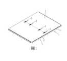
參閱圖1至圖3,本發明電子裝置之一實施例,包含兩個機殼1、四個多連桿式鉸鏈2,及一軟性螢幕3。在本實施例中,該電子裝置是以一折疊式手機為例說明。另外,該等多連桿式鉸鏈2也可作為一筆記型電腦的顯示螢幕與指令輸入區之間的樞軸,不以本實施例為限。Referring to FIGS. 1 to 3, an embodiment of an electronic device of the present invention includes two
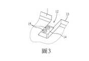
該等機殼1連接於該等多連桿式鉸鏈2的相反兩端,該軟性螢幕3覆蓋於該等機殼1與該等多連桿式鉸鏈2。每一機殼1包括一機體11、四個間隔形成於該機體11同一側緣的連接槽12、一用以連接該柔性螢幕3的接合面13、四個分別對應於該等連接槽12且背向該接合面13的連接面14,及八個兩兩對應地形成於該等連接面14的凸柱15。The
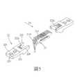
另配合參閱圖4至圖6,每一多連桿式鉸鏈2設置於該等機殼1相對應的連接槽12,並包括四個連桿組21、兩個連接座22,及八個軸桿23。Referring also to FIGS. 4 to 6, each
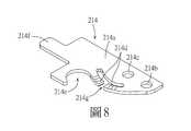
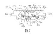
參閱圖7至圖9,其中圖7是沿圖5中的一第一方向D1檢視的多連桿式鉸鏈2,圖9是多連桿式鉸鏈2中的任一連桿組21。每一連桿組21具有一基桿211、兩個摩擦連桿212、兩個同步連桿213,及兩個扭力板214。該基桿211具有一第一桿體211a、兩個分別位於該第一桿體211a相反兩端的連接端部211b、兩個位於該等連接端部211b之間的第一中樞接部211c,及兩個形成於該第一桿體211a的一側緣且分別位於兩相鄰的該第一中樞接部211c與該連接端部211b之間的第一側凹部211d。該等摩擦連桿212分別樞設於該基桿211的該等連接端部211b,且每一摩擦連桿212具有一第二桿體212a、一位於該第二桿體212a一端且樞設於對應的連接端部211b的第一樞轉端部212b、一相反於該第一樞轉端部212b的第二樞轉端部212c,及一介於該第一樞轉端部212b與該第二樞轉端部212c之間且形成於第二桿體212a一側緣的第二側凹部212d。該等同步連桿213分別樞設於該等摩擦連桿212的該等第一中樞接部211c,且每一同步連桿213具有一樞設於對應的第一中樞接部211c的第一連動端部213a,及一相反於該第一連動端部213a的第二連動端部213b。每一第一連動端部213a的外緣形成輪齒狀,且該等同步連桿213的該等第一連動端部213a藉由輪齒相互嚙合。每一扭力板214具有一板體214a、一位於該板體214a一端且樞設於該同步連桿213的第二連動端部213b的第三樞轉端部214b、一鄰近該第三樞轉端部214b且樞設於該摩擦連桿212的第二樞轉端部212c的第二中樞接部214c、一形成於該板體214a一側緣且與該板體214a不共平面的側凸部214d、一連接於該側凸部214d且與該基桿211的連接端部211b形狀相配合的定位槽214e,及一凸設於該板體214a且遠離該第三樞轉端部214b的凸緣部214f。於本實施例中,每一連桿組21中的該側凸部214d朝相鄰的該摩擦連桿212方向凸出,並具有一斷口處214g,不過在變化的實施例中,該側凸部214d也可不具有該斷口處214g。此外,於本實施例中,每一多連桿式鉸鏈2還包括另外一個基桿211及另外兩個扭力板214。該等連桿組21與另外的該基桿211及該等扭力板214藉由該等軸桿23相互樞接。Referring to FIGS. 7 to 9, FIG. 7 is a
另配合參閱圖3與圖5,每一連接座22具有一座體221、一位於該座體221一端以連接該等扭力板214的連接部222、一位於該連接部222相反位置且自該座體221表面凹設形成的承載部223,及一形成於該連接部222的上表面224。該連接部222具有五個供該等扭力板214的凸緣部214f對應焊接固定的插槽222a。該承載部223用以伸入對應的機殼1的連接槽12,且該承載部223具有兩個貫孔223a,每一機殼1的連接面14對應設置於該承載部223並使該等凸柱15卡合於該等貫孔223a,再藉由鎖固件(圖未示)螺鎖固定。Referring also to FIGS. 3 and 5, each connecting
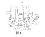
參閱圖9至圖11,該等扭力板214能藉由該等同步連桿213同步轉動,使得連接於該等多連桿式鉸鏈2兩側的該等機殼1(見圖1~2)能以同步且對稱的方式作動,且該等扭力板214可相對於該基桿211在一如圖9所示的展開位置與一如圖11所示的收合位置間轉換,該等機殼1受該等扭力板214連動而完全開啟(見圖1)或完全閉合(見圖12)。具體而言,當該等扭力板214在該展開位置,該等扭力板214平行於該基桿211,該等第三樞轉端部214b對齊於該等第一中樞接部211c上方並相互靠近,該等定位槽214e對應位於該基桿211的該等連接端部211b,該等側凸部214d分別對應容置於該基桿211的該等第一側凹部211d界定出的第一側凹空間211e,且該等側凸部214d與該等板體214a的相連處會受壓於該等摩擦連桿212,並與該等摩擦連桿212干涉配合產生一第一扭力值。此外,另配合參閱圖1、圖2及圖4,該等連接座22的連接部222相互靠近,且該等連接座22的該等上表面224相互平行並與該機殼1的接合面13齊平,以使該軟性螢幕3呈平坦狀。Referring to FIGS. 9 to 11, the
當使用者收合本電子裝置,該等扭力板214會如圖10所示地從該展開位置往該收合位置樞轉。在樞轉的過程中,該等凸緣部214f會受該等連接座22(見圖5)帶動而相向轉動靠近,該等第三樞轉端部214b會連動該等同步連桿213的該等第二連動端部213b往對應的摩擦連桿212樞轉,且同時該等第二中樞接部214c會帶動該等摩擦連桿212的該等第二樞轉端部212c往斜上方移動,使該等摩擦連桿212些微外張,該等同步連桿213的該等第二連動端部213b即可順勢轉入該等摩擦連桿212的該等第二側凹部212d界定出的第二側凹空間212e。此外,在該展開位置與該收合位置的轉換過程中,該等摩擦連桿212會壓抵於該等側凸部214d的斷口處214g,且該等側凸部214d的斷口處214g為該等側凸部214d變形量最大處,與該等摩擦連桿212產生的干涉量最大,是以該等摩擦連桿212會與該等側凸部214d干涉配合產生一第二扭力值,且該第二扭力值大於該第一扭力值。When the user collapses the electronic device, the
參閱圖11至圖13,當該等扭力板214樞轉至在該收合位置,該等扭力板214橫交於該基桿211,該等第三樞轉端部214b相互遠離,並與該等同步連桿213的該等第二連動端部213b一起收容於該等第二側凹空間212e,以形成一彎折空間4。該等側凸部214d的斷口處214g脫離該等摩擦連桿212的壓抵,使該等摩擦連桿212僅壓抵於該等側凸部214d與該等板體214a的相連處,並與該等側凸部214d干涉配合產生一第三扭力值,且該第三扭力值小於該第二扭力值。由於該第一扭力值與該第三扭力值皆小於該第二扭力值,使用者能較為省力地扳動該等機殼1開啟或閉合,且有助於維持該等機殼1開啟或閉合狀態。於本實施例中,當該等扭力板214樞轉至在該收合位置,該等扭力板214是垂直於該基桿211,但並不以此為限,在其他態樣的實施方式中,該等扭力板214與該基桿211的夾角也可以是略大於90度或略小於90度或等於90度,只要能使該等機殼1完整地閉合即可。此外,該軟性螢幕3呈彎折狀,且該軟性螢幕3的彎折處收容於該彎折空間4,避免軟性螢幕3彎折時沒有足夠的空間收納彎折處,造成軟性螢幕3擠壓毀損。Referring to FIGS. 11 to 13, when the
綜上所述,本發明電子裝置藉由設置同步連桿213,使扭力板214從展開位置到收合位置的轉換過程中,該等扭力板214能同步轉動並使第三樞轉端部214b同步地相互遠離,形成一彎折空間4,供螢幕的彎折處容置,避免軟性螢幕3受到擠壓毀損;另外,由於該第一扭力值與該第三扭力值皆小於該第二扭力值,使用者因此能較為省力地開啟或閉合該電子裝置,故確實能達成本發明之目的。In summary, the electronic device of the present invention, by providing the
惟以上所述者,僅為本發明之實施例而已,當不能以此限定本發明實施之範圍,凡是依本發明申請專利範圍及專利說明書內容所作之簡單的等效變化與修飾,皆仍屬本發明專利涵蓋之範圍內。However, the above are only examples of the present invention, and should not be used to limit the scope of the present invention. Any simple equivalent changes and modifications made according to the scope of the patent application of the present invention and the content of the patent specification are still classified as This invention covers the patent.
1:機殼11:機體12:連接槽13:接合面14:連接面15:凸柱2:多連桿式鉸鏈21:連桿組211:基桿211a:第一桿體211b:連接端部211c:第一中樞接部211d:第一側凹部211e:第一側凹空間212:摩擦連桿212a:第二桿體212b:第一樞轉端部212c:第二樞轉端部212d:第二側凹部212e:第二側凹空間213:同步連桿213a:第一連動端部213b:第二連動端部214:扭力板214a:板體214b:第三樞轉端部214c:第二中樞接部214d:側凸部214e:定位槽214f:凸緣部214g:斷口處22:連接座221:座體222:連接部222a:插槽223:承載部223a:貫孔224:上表面23:軸桿3:軟性螢幕4:彎折空間D1:第一方向1: Case 11: Body 12: Connection groove 13: Joint surface 14: Connection surface 15: Convex column 2: Multi-link hinge 21: Link group 211: Base rod 211a:
本發明之其他的特徵及功效,將於參照圖式的實施方式中清楚地呈現,其中: 圖1是本發明電子裝置的一實施例的一立體圖; 圖2是該實施例的一立體分解圖; 圖3是一不完整的立體圖,說明該實施例的一機殼的一連接面上有兩個凸柱; 圖4是該實施例的一多連桿式鉸鏈的一立體圖; 圖5是該多連桿式鉸鏈的一立體分解圖; 圖6是該多連桿式鉸鏈的一局部立體分解圖; 圖7是沿圖5中的一第一方向D1的一局部側視圖; 圖8是一立體圖,說明該多連桿式鉸鏈的一扭力板; 圖9是圖7的該多連桿式鉸鏈的兩個扭力板與一個基桿取下的一側視圖,說明該等扭力板在一展開位置; 圖10是該等扭力板從該展開位置至一收合位置的樞轉過程的一側視圖; 圖11是一側視圖,說明該等扭力板在該收合位置的態樣; 圖12是一立體圖,說明當該等扭力板在該收合位置時,該實施例的兩個機殼的態樣;及 圖13是圖12的一局部放大圖,說明該實施例的一軟性螢幕的彎折處收容於該實施例的一彎折空間。Other features and functions of the present invention will be clearly presented in the embodiment with reference to the drawings, in which: FIG. 1 is a perspective view of an embodiment of the electronic device of the present invention; FIG. 2 is an exploded view of the embodiment Fig. 3 is an incomplete perspective view illustrating that there are two convex posts on a connecting surface of a casing of this embodiment; Fig. 4 is a perspective view of a multi-link hinge of this embodiment; Fig. 5 is the A perspective exploded view of the multi-link hinge; FIG. 6 is a partial perspective exploded view of the multi-link hinge; FIG. 7 is a partial side view along a first direction D1 in FIG. 5; FIG. 8 is a A perspective view illustrating a torsion plate of the multi-link hinge; FIG. 9 is a side view of two torsion plates and a base rod of the multi-link hinge of FIG. 7 taken away, illustrating that the torsion plates are expanded FIG. 10 is a side view of the pivoting process of the torsion plates from the deployed position to a retracted position; FIG. 11 is a side view illustrating the state of the torsion plates in the retracted position; FIG. 12 Is a perspective view illustrating the appearance of the two cabinets of the embodiment when the torsion plates are in the collapsed position; and FIG. 13 is a partially enlarged view of FIG. 12 illustrating a flexible screen of the embodiment The bending place is accommodated in a bending space of this embodiment.
1:機殼1: chassis
12:連接槽12: connection slot
13:接合面13: Joint surface
2:多連桿式鉸鏈2: Multi-link hinge
3:軟性螢幕3: soft screen
Claims (15)
Translated fromChinesePriority Applications (2)
| Application Number | Priority Date | Filing Date | Title |
|---|---|---|---|
| TW107131344ATWI675356B (en) | 2018-09-06 | 2018-09-06 | Multi-link hinge and electronic device |
| US16/228,366US10401917B1 (en) | 2018-09-06 | 2018-12-20 | Multi-linkage hinge and electronic device having the same |
Applications Claiming Priority (1)
| Application Number | Priority Date | Filing Date | Title |
|---|---|---|---|
| TW107131344ATWI675356B (en) | 2018-09-06 | 2018-09-06 | Multi-link hinge and electronic device |
Publications (2)
| Publication Number | Publication Date |
|---|---|
| TWI675356B TWI675356B (en) | 2019-10-21 |
| TW202011366Atrue TW202011366A (en) | 2020-03-16 |
Family
ID=67770213
Family Applications (1)
| Application Number | Title | Priority Date | Filing Date |
|---|---|---|---|
| TW107131344ATWI675356B (en) | 2018-09-06 | 2018-09-06 | Multi-link hinge and electronic device |
Country Status (2)
| Country | Link |
|---|---|
| US (1) | US10401917B1 (en) |
| TW (1) | TWI675356B (en) |
Cited By (1)
| Publication number | Priority date | Publication date | Assignee | Title |
|---|---|---|---|---|
| WO2021184654A1 (en)* | 2020-03-20 | 2021-09-23 | 华为技术有限公司 | Rotating shaft mechanism and foldable terminal device |
Families Citing this family (35)
| Publication number | Priority date | Publication date | Assignee | Title |
|---|---|---|---|---|
| US10564682B1 (en)* | 2019-03-29 | 2020-02-18 | Fositek Corporation | Hinge mechanism and flexible electronic device having the same |
| US10599189B1 (en)* | 2019-04-26 | 2020-03-24 | Fositek Corporation | Bendable support apparatus for a flexible display |
| JP7043463B2 (en)* | 2019-07-09 | 2022-03-29 | 三菱製鋼株式会社 | Hinge |
| TWI688324B (en)* | 2019-08-02 | 2020-03-11 | 宏碁股份有限公司 | Foldable electronic device |
| TWI698591B (en)* | 2019-10-29 | 2020-07-11 | 富世達股份有限公司 | Display device and its hinge mechanism |
| CN112727906B (en)* | 2019-10-29 | 2024-04-26 | 深圳市富世达通讯有限公司 | Display device and hinge mechanism thereof |
| KR102668216B1 (en) | 2019-12-02 | 2024-05-23 | 삼성전자주식회사 | Foldable electronic device including hinge assembly |
| KR102784368B1 (en)* | 2019-12-02 | 2025-03-19 | 엘지디스플레이 주식회사 | Foldable display device |
| EP4007945A1 (en) | 2019-12-10 | 2022-06-08 | Google LLC | Hinge mechanism and foldable device having same |
| TWI723702B (en)* | 2019-12-26 | 2021-04-01 | 富世達股份有限公司 | Shaft chain group structure |
| CN211550435U (en)* | 2020-02-12 | 2020-09-22 | Oppo广东移动通信有限公司 | Synchronous rotating mechanism, foldable shell assembly and foldable electronic equipment |
| TWI764565B (en)* | 2020-03-30 | 2022-05-11 | 仁寶電腦工業股份有限公司 | Electronic device and hinge assembly thereof |
| CN113660798B (en)* | 2020-05-12 | 2022-10-18 | Oppo广东移动通信有限公司 | Synchronous shaft mechanism, foldable housing assembly and foldable electronic device |
| EP4155863B1 (en) | 2020-07-13 | 2025-08-27 | Samsung Electronics Co., Ltd. | Hinge structure for foldable electronic device and electronic device comprising same |
| CN111885236B (en)* | 2020-07-27 | 2021-07-27 | Oppo广东移动通信有限公司 | Electronic equipment and synchronous rotating mechanism thereof |
| CN111977199B (en)* | 2020-08-28 | 2025-06-13 | 天津华派集装箱制造有限公司 | A fast-expanding folding box house |
| KR102849762B1 (en)* | 2020-09-14 | 2025-08-26 | 삼성전자주식회사 | Structure of Link Hinge and electronic device including the same |
| US11505322B2 (en)* | 2020-10-05 | 2022-11-22 | B/E Aerospace, Inc. | Arm cap friction hinge mechanism |
| JP2022063700A (en)* | 2020-10-12 | 2022-04-22 | レノボ・シンガポール・プライベート・リミテッド | Portable information apparatus and hinge device |
| TWI746217B (en)* | 2020-10-20 | 2021-11-11 | 宏碁股份有限公司 | Hinge structure for flexible display and portable electronic device |
| CN114483761A (en)* | 2020-10-23 | 2022-05-13 | 宏碁股份有限公司 | A hinge structure and a foldable electronic device for a flexible screen |
| KR20220101300A (en)* | 2021-01-11 | 2022-07-19 | 삼성전자주식회사 | An electronic device configured to adaptively open and close a foldable housing |
| KR102863276B1 (en) | 2021-01-12 | 2025-09-24 | 삼성전자주식회사 | Hinge Structure using a actuator and Foldable Electronic Device having the same |
| TWI747708B (en)* | 2021-01-12 | 2021-11-21 | 富世達股份有限公司 | Two-axis synchronous hinge |
| TWI748917B (en)* | 2021-04-21 | 2021-12-01 | 富世達股份有限公司 | Two-axis synchronous hinge |
| TWI764720B (en)* | 2021-05-17 | 2022-05-11 | 富世達股份有限公司 | Dual axis synchronous hinge |
| TWI751083B (en)* | 2021-05-17 | 2021-12-21 | 富世達股份有限公司 | Two-axis synchronous hinge |
| US12314088B2 (en)* | 2021-07-22 | 2025-05-27 | Samsung Electronics Co., Ltd. | Hinge apparatus and electronic device including the same |
| US12164344B2 (en)* | 2021-08-11 | 2024-12-10 | Apple Inc. | Hinges for folding display devices |
| CN115883693B (en)* | 2021-09-26 | 2024-06-14 | 华为技术有限公司 | Foldable electronic device and hinge mechanism |
| TWM631213U (en)* | 2022-05-12 | 2022-08-21 | 鑫禾科技股份有限公司 | Pivot device |
| TWI815560B (en)* | 2022-07-15 | 2023-09-11 | 振樺電子股份有限公司 | Sales terminal casing opening device |
| US12436576B2 (en)* | 2022-10-31 | 2025-10-07 | Lenovo (Singapore) Pte. Ltd. | Computing device |
| TWI852444B (en)* | 2023-03-28 | 2024-08-11 | 富世達股份有限公司 | Multi-link hinge |
| CN118855840A (en)* | 2023-04-27 | 2024-10-29 | 华为技术有限公司 | A rotating shaft mechanism and electronic equipment |
Family Cites Families (14)
| Publication number | Priority date | Publication date | Assignee | Title |
|---|---|---|---|---|
| DE9200642U1 (en)* | 1992-01-21 | 1993-05-19 | Pies, Gerrit, 5650 Solingen | Connection of profile bars |
| TWM453754U (en)* | 2012-12-21 | 2013-05-21 | First Dome Corp | Plugging type multi-section rotating shaft structure |
| TWM453755U (en)* | 2012-12-21 | 2013-05-21 | First Dome Corp | Synchronous expanding and folding device |
| TWM453753U (en)* | 2012-12-21 | 2013-05-21 | First Dome Corp | Multi-section type rotating shaft structure |
| KR102215597B1 (en)* | 2013-12-23 | 2021-02-15 | 삼성전자주식회사 | Electronic apparatus |
| US9684343B2 (en)* | 2014-06-12 | 2017-06-20 | Microsoft Technology Licensing, Llc | Radius hinge |
| TWM498254U (en)* | 2014-09-26 | 2015-04-01 | First Dome Corp | Multi-section rotary shaft improved structure |
| CN106286577A (en)* | 2015-06-12 | 2017-01-04 | 联想(北京)有限公司 | Multi-axis hinge and electronic equipment |
| TWM513283U (en)* | 2015-08-05 | 2015-12-01 | Paor Tsann Entpr Co Ltd | Folding flap |
| US10036189B2 (en)* | 2015-12-28 | 2018-07-31 | Lianhong Art Co., Ltd. | Synchronous hinge device |
| CA3034146A1 (en)* | 2016-07-19 | 2018-01-25 | Shenzhen Royole Technologies Co., Ltd. | Flexible device |
| TWM533844U (en)* | 2016-07-27 | 2016-12-11 | First Dome Corp | Multi-axis type rotating shaft linkage device |
| US11214999B2 (en)* | 2017-02-13 | 2022-01-04 | Hewlett-Packard Development Company, L.P. | Friction hinges |
| TWM546082U (en)* | 2017-05-08 | 2017-07-21 | 新日興股份有限公司 | Hinge and electronic device using the same |
- 2018
- 2018-09-06TWTW107131344Apatent/TWI675356B/enactive
- 2018-12-20USUS16/228,366patent/US10401917B1/enactiveActive
Cited By (1)
| Publication number | Priority date | Publication date | Assignee | Title |
|---|---|---|---|---|
| WO2021184654A1 (en)* | 2020-03-20 | 2021-09-23 | 华为技术有限公司 | Rotating shaft mechanism and foldable terminal device |
Also Published As
| Publication number | Publication date |
|---|---|
| US10401917B1 (en) | 2019-09-03 |
| TWI675356B (en) | 2019-10-21 |
Similar Documents
| Publication | Publication Date | Title |
|---|---|---|
| TW202011366A (en) | Multi-link hinge and electronic device in which the torsion plate may be rotated synchronously by the synchronizing link | |
| CN212812291U (en) | Folding electronic device and hinge module thereof | |
| CN115076218A (en) | Electronic device and folding device | |
| TWI698591B (en) | Display device and its hinge mechanism | |
| US11079808B2 (en) | Dual-axis hinge assembly and electronic device | |
| CN114115455A (en) | Articulation module and foldable electronic device including articulation module | |
| TW202107964A (en) | Foldable electronic device | |
| TW202100883A (en) | Foldable display device and a hinge mechanism | |
| TW202010952A (en) | Sliding hinge and electronic deivce having the same | |
| CN105407194A (en) | Mobile terminal with flexible screen | |
| CN217814531U (en) | Elastic parts, shaft devices and electronic equipment | |
| CN103235638B (en) | Electronic installation and extended base thereof | |
| TW202142085A (en) | Folding-type electronic device | |
| CN109973514A (en) | Links, hinges and mobile terminals | |
| CN108932019B (en) | Electronic device | |
| CN109194784B (en) | Multi-link hinge and electronic device | |
| TWM625172U (en) | Pivot for dual screens | |
| CN209746453U (en) | Display screen folding structure | |
| CN113496651B (en) | Flexible screen support device, flexible screen module and electronic equipment | |
| TWM510988U (en) | Dual hinge structure capable of synchronously rotating | |
| TWI531302B (en) | Hinge structure | |
| CN218213964U (en) | foldable electronic device | |
| CN219865869U (en) | Folding mechanism and electronic equipment | |
| CN212003923U (en) | Electronic device with hinged hinge | |
| TWI858923B (en) | Foldable electronic device |