TW202009701A - Testing system and testing device with remote control function - Google Patents
Testing system and testing device with remote control functionDownload PDFInfo
- Publication number
- TW202009701A TW202009701ATW107129954ATW107129954ATW202009701ATW 202009701 ATW202009701 ATW 202009701ATW 107129954 ATW107129954 ATW 107129954ATW 107129954 ATW107129954 ATW 107129954ATW 202009701 ATW202009701 ATW 202009701A
- Authority
- TW
- Taiwan
- Prior art keywords
- computer
- signal
- tested
- remote control
- transmission port
- Prior art date
Links
- 238000012360testing methodMethods0.000titleclaimsabstractdescription84
- 230000005540biological transmissionEffects0.000claimsabstractdescription91
- 238000004088simulationMethods0.000claimsabstract3
- 238000001514detection methodMethods0.000claimsdescription82
- 238000012545processingMethods0.000claimsdescription37
- 230000001419dependent effectEffects0.000claims1
- 238000000034methodMethods0.000abstractdescription5
- 230000006870functionEffects0.000description26
- 238000013024troubleshootingMethods0.000description8
- 238000010586diagramMethods0.000description4
- 238000009434installationMethods0.000description3
- 230000002093peripheral effectEffects0.000description2
- 238000011161developmentMethods0.000description1
- 230000005611electricityEffects0.000description1
- 238000007689inspectionMethods0.000description1
- 230000007257malfunctionEffects0.000description1
- 238000012986modificationMethods0.000description1
- 230000004048modificationEffects0.000description1
Images

Landscapes
- Selective Calling Equipment (AREA)
Abstract
Description
Translated fromChinese本發明係關於一種檢測裝置與系統,特別是關於一種具遠端控制功能的檢測裝置與系統。The invention relates to a detection device and system, in particular to a detection device and system with remote control function.
隨著各種電子設備被廣泛使用於生活中,可能因為人為因素或者品質因素,難免會造成電子設備故障而無法順利操作。以電腦製造商為例,當工廠中正在製造的電腦無法開機時,往往需要有經驗的研發工程師前往處理,以便判讀真正的故障原因,並執行正確的故障排除方案。但是,若工廠在不同城市或國家,可能造成研發工程師無法兼顧,難以及時前往處理的情況。As various electronic devices are widely used in life, they may inevitably cause malfunctions of electronic devices due to human factors or quality factors, and cannot be operated smoothly. Take the computer manufacturer as an example. When the computer being manufactured in the factory cannot be turned on, an experienced R&D engineer is often required to deal with it in order to interpret the true cause of the failure and implement the correct troubleshooting solution. However, if the factories are in different cities or countries, it may cause the situation that the R&D engineers cannot take care of it and it is difficult to go to the treatment in time.
若研發工程師無法前往現場,傳統的故障排除方案,係由現場人員寫信或打電話研發工程師,告知故障的細節,由研發工程師判讀可能發生故障的原因之後,再告知現場人員,並由現場人員執行研發工程師認為最有機會排除故障的方案。一般來說,現場人員常常因為缺乏經驗,無法正確描述故障情況,且因缺乏相關知識,也無法正確執行研發工程師交代的故障排除方案,從而妨礙了故障排除的效率。If the R&D engineer cannot go to the site, the traditional troubleshooting solution is that the on-site personnel write or call the R&D engineer to inform the details of the failure, and after the R&D engineer interprets the reason for the possible failure, then notify the on-site personnel Executive R & D engineer thinks that there is the most opportunity to troubleshoot the program. Generally speaking, on-site personnel are often unable to correctly describe the fault situation due to lack of experience, and due to lack of relevant knowledge, they cannot correctly implement the troubleshooting solution explained by the R&D engineer, which hinders the efficiency of troubleshooting.
因此,目前業界需要一種新的檢測裝置,不僅要讓研發工程師能夠直接取得故障的相關資訊,也要讓研發工程師不受距離的限制,能夠遠端執行正確的故障排除方案。Therefore, the industry currently needs a new detection device that not only allows R&D engineers to directly obtain information about failures, but also allows R&D engineers to perform correct troubleshooting solutions remotely without distance limitations.
本發明提供一種具遠端控制功能的檢測裝置與系統,能夠直接拍攝待測電腦,讓研發工程師能直接看到待測電腦的資訊,並將研發工程師的操作輸入方式直接轉換成模擬操作信號,再將模擬操作信號饋入待測電腦,使待測電腦如同直接被研發工程師控制,使研發工程師能執行正確的故障排除方案。The invention provides a detection device and system with remote control function, which can directly photograph the computer to be tested, so that the R&D engineer can directly see the information of the computer to be tested, and directly convert the operation input mode of the R&D engineer into an analog operation signal. Then the analog operation signal is fed into the computer under test, so that the computer under test is controlled directly by the R&D engineer, so that the R&D engineer can execute the correct troubleshooting solution.
本發明提出一種具遠端控制功能的檢測裝置,用以檢測待測電腦,待測電腦具有待測傳輸連接埠。檢測裝置包含處理單元、第一傳輸連接埠以及影像傳輸連接埠。處理單元依據遠端控制信號,選擇性地產生模擬操作信號或影像擷取信號。第一傳輸連接埠耦接處理單元並且可插拔地耦接待測傳輸連接埠,模擬操作信號經由第一傳輸連接埠輸入待測傳輸連接埠。影像傳輸連接埠耦接處理單元並且可插拔地耦接影像擷取裝置,用以傳輸影像擷取信號,以及接收影像資訊。其中,模擬操作信號係用以模擬待測電腦的鍵盤操作信號、滑鼠操作信號或觸控操作信號,影像擷取裝置受控於影像擷取信號,用以拍攝待測電腦據以產生影像資訊。The invention provides a detection device with a remote control function for detecting a computer to be tested. The computer to be tested has a transmission port to be tested. The detection device includes a processing unit, a first transmission port and an image transmission port. The processing unit selectively generates an analog operation signal or an image capture signal according to the remote control signal. The first transmission port is coupled to the processing unit and is removably coupled to the reception transmission port, and the analog operation signal is input to the transmission port to be tested through the first transmission port. The image transmission port is coupled to the processing unit and is removably coupled to the image capture device for transmitting image capture signals and receiving image information. The analog operation signal is used to simulate the keyboard operation signal, mouse operation signal or touch operation signal of the computer under test, and the image capture device is controlled by the image capture signal to capture the computer under test to generate image information .
於一個例子中,影像擷取信號用以指示影像擷取裝置拍攝待測電腦的螢幕畫面、組裝線路或硬體設備。此外,檢測裝置可更包含第一通用連接埠,耦接處理單元並且可插拔地耦接待測電腦的待測通用連接埠,用以接收待測電腦的除錯信號。另外,處理單元更可依據遠端控制信號,選擇性地產生系統控制信號,第一通用連接埠更用以傳輸系統控制信號至待測通用連接埠。In one example, the image capture signal is used to instruct the image capture device to capture the screen of the computer under test, assembling lines or hardware equipment. In addition, the detection device may further include a first general-purpose port, coupled to the processing unit and removably coupled to the general-purpose port to be tested of the computer under test, for receiving a debugging signal of the computer under test. In addition, the processing unit can selectively generate system control signals according to the remote control signals. The first universal port is further used to transmit the system control signal to the universal port to be tested.
於另一個例子中,檢測裝置更包含燒錄裝置連接埠,耦接處理單元並且可插拔地耦接燒錄裝置,處理單元更依據遠端控制信號,選擇性地產生燒錄控制信號,燒錄裝置受控於燒錄控制信號,用以更新待測電腦的韌體。In another example, the detection device further includes a programming device port, coupled to the processing unit and removably coupled to the programming device, the processing unit further selectively generates a programming control signal according to the remote control signal, programming The recording device is controlled by the burning control signal to update the firmware of the computer under test.
本發明提出一種具遠端控制功能的檢測系統,用以檢測待測電腦,待測電腦具有待測傳輸連接埠。檢測系統包含遠端裝置、檢測裝置以及影像擷取裝置。遠端裝置用以產生遠端控制信號。檢測裝置包含處理單元、第一傳輸連接埠以及影像傳輸連接埠。處理單元依據遠端控制信號,選擇性地產生模擬操作信號或影像擷取信號。第一傳輸連接埠耦接處理單元並且可插拔地耦接待測傳輸連接埠,模擬操作信號經由第一傳輸連接埠輸入待測傳輸連接埠。影像傳輸連接埠耦接處理單元,用以傳輸影像擷取信號,以及接收影像資訊。影像擷取裝置可插拔地耦接影像傳輸連接埠,受控於影像擷取信號,用以拍攝待測電腦據以產生影像資訊。其中,模擬操作信號係用以模擬待測電腦的鍵盤操作信號、滑鼠操作信號或觸控操作信號。The invention provides a detection system with a remote control function for detecting a computer to be tested, the computer to be tested has a transmission port to be tested. The detection system includes a remote device, a detection device, and an image capture device. The remote device is used to generate remote control signals. The detection device includes a processing unit, a first transmission port and an image transmission port. The processing unit selectively generates an analog operation signal or an image capture signal according to the remote control signal. The first transmission port is coupled to the processing unit and is removably coupled to the reception transmission port, and the analog operation signal is input to the transmission port to be tested through the first transmission port. The image transmission port is coupled to the processing unit, and is used to transmit image capture signals and receive image information. The image capture device is pluggably coupled to the image transmission port and is controlled by the image capture signal, which is used to capture the computer data to be tested to generate image information. The analog operation signal is used to simulate the keyboard operation signal, mouse operation signal or touch operation signal of the computer to be tested.
綜上所述,本發明提供的具遠端控制功能的檢測裝置與系統,可以利用影像擷取裝置拍攝待測電腦,讓研發工程師能直接看到待測電腦的螢幕、接線與硬體相關的資訊,更能將研發工程師的操作輸入方式直接轉換成模擬操作信號,再將模擬操作信號饋入待測電腦。藉此,檢測裝置與系統可以使待測電腦如同直接被研發工程師控制,讓研發工程師能執行正確的故障排除方案。In summary, the detection device and system with remote control function provided by the present invention can use the image capture device to shoot the computer under test, so that the R&D engineer can directly see the screen, wiring and hardware related to the computer under test Information, can also directly convert the operation input method of the R&D engineer into an analog operation signal, and then feed the analog operation signal into the computer to be tested. In this way, the detection device and system can make the computer under test as if it is directly controlled by the R&D engineer, so that the R&D engineer can execute the correct troubleshooting solution.
下文將進一步揭露本發明之特徵、目的及功能。然而,以下所述者,僅為本發明之實施例,當不能以之限制本發明之範圍,即但凡依本發明申請專利範圍所作之均等變化及修飾,仍將不失為本發明之要意所在,亦不脫離本發明之精神和範圍,故應將視為本發明的進一步實施態樣。The features, purposes, and functions of the present invention will be further disclosed below. However, the following are only examples of the present invention, which should not be used to limit the scope of the present invention, that is, any changes and modifications made in accordance with the scope of the patent application of the present invention will still be the gist of the present invention, Without departing from the spirit and scope of the present invention, it should be regarded as a further embodiment of the present invention.
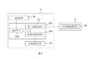
請參閱圖1,圖1係繪示依據本發明一實施例之具遠端控制功能的檢測系統的功能方塊圖。如圖1所示,具遠端控制功能的檢測系統1包含了遠端裝置10、檢測裝置12以及影像擷取裝置14,遠端裝置10可以是有線或無線地電性連接檢測裝置12,只要檢測裝置12可以與遠端裝置10交換資料與信號,皆應屬本實施例之範疇。此外,影像擷取裝置14有可能有線或無線地電性連接檢測裝置12,此外於一個例子中,影像擷取裝置14也能整合在檢測裝置12中,本實施例不加以限制。另外,檢測裝置12可插拔地電性連接到待測電腦2,用以進行待測電腦2的檢測作業。這裡所說的檢測作業,可以是檢查待測電腦2的各項功能是否正常,或者排除待測電腦2的各種故障,至於欲檢查何種功能或欲排除何種故障,本實施例在此不加以限制。以下分別說明具遠端控制功能的檢測系統1中的各個裝置。Please refer to FIG. 1, which is a functional block diagram of a detection system with a remote control function according to an embodiment of the present invention. As shown in FIG. 1, the
遠端裝置10係用以產生遠端控制信號。於一個例子中,遠端裝置10與檢測裝置12位於不同的地理位置,而檢測裝置12鄰近於待測電腦2。例如,研發工程師可以在某一廠房操作遠端裝置10,提供遠端控制信號,以遠端遙控另一個廠房的檢測裝置12進行待測電腦2的檢測作業。實務上,遠端裝置10可以安裝用來遙控檢測裝置12的應用程式,從而研發工程師可以從所述應用程式提供的介面操作檢測裝置12,或者藉由所述應用程式提供的介面,操作所有電性連接到檢測裝置12的周邊設備。在此,遠端控制信號可以泛指所有遠端裝置10發出的信號,例如,遠端控制信號可以要求檢測裝置12傳送特定信號給待測電腦2;遠端控制信號可以驅動檢測裝置12執行特定軟體或硬體功能;或者,遠端控制信號可以控制電性連接到檢測裝置12的周邊設備等,本實施例不加以限制。The
檢測裝置12包含處理單元120、第一傳輸連接埠122以及影像傳輸連接埠124,處理單元120分別電性連接第一傳輸連接埠122以及影像傳輸連接埠124。處理單元120可以依據遠端控制信號,選擇性地產生模擬操作信號或影像擷取信號,本實施例在此不限制處理單元120是否有其他功能。實務上,檢測裝置12還可以有用於遠距離傳輸信號的傳輸單元(圖未示),處理單元120可藉由所述遠距離傳輸信號的傳輸單元,處理遠端裝置10發出的遠端控制信號,或將檢測裝置12取得的資料回傳至遠端裝置10。於一個例子中,檢測裝置12可以是桌上型電腦、筆記型電腦、平板電腦或者是其他有運算能力的電子設備。The
檢測裝置12具有兩種不同類型的連接埠,特別是符合USB規範的第一傳輸連接埠122,以及符合影像傳輸規範的影像傳輸連接埠124。實務上,第一傳輸連接埠122可以選用任何一種熱插拔接頭,例如USB 規格下的type A、type B、mini A、mini B、micro A、micro B或type C等熱插拔接頭。為了方便說明,以下以第一傳輸連接埠122與待測傳輸連接埠20均為USB規格的連接埠為例,但值得注意的是,本實施例不限制第一傳輸連接埠122與待測傳輸連接埠20必須要是相同規格。於一個例子中,縱然第一傳輸連接埠122與待測傳輸連接埠20規格不同,但是如果使用適當的線材轉接後,便能使第一傳輸連接埠122與待測傳輸連接埠20互相傳遞信號,則應仍屬本實施例之範疇。The
實務上,第一傳輸連接埠122係用來將模擬操作信號輸入待測傳輸連接埠20,模擬操作信號可以是用以模擬待測電腦2的鍵盤操作信號、滑鼠操作信號或觸控操作信號。以實際的例子來說,待測電腦2於一般使用時,原本即設計可使用USB連接埠外接鍵盤、滑鼠、觸控板等輸入設備,所述USB連接埠即可以是本實施例所稱的待測傳輸連接埠20。當第一傳輸連接埠122與待測傳輸連接埠20電性連接之後,檢測裝置12便可以模擬待測電腦2外接的鍵盤、滑鼠、觸控板等輸入設備,提供對應的模擬操作信號給待測電腦2。換句話說,待測電腦2會認為待測傳輸連接埠20正在連線到外接鍵盤、滑鼠、觸控板等輸入設備,並讀取待測傳輸連接埠20接收到的鍵盤操作信號、滑鼠操作信號或觸控操作信號。In practice, the
此時,研發工程師可以從遠端裝置10連線檢測裝置12,使檢測裝置12產生模擬操作信號控制待測電腦2。有別於直接從遠端裝置10遙控待測電腦2,本實施例更著重在模擬待測電腦2外接的鍵盤、滑鼠、觸控板等輸入設備。其原因在於,待測電腦2發生故障時,很有可能無法正常開機,更無法連上網路,從而研發工程師不一定有機會直接從遠端裝置10下指令給待測電腦2。此外,除了前揭待測電腦2可能無法連上網路的問題之外,待測電腦2通常要搭配特定晶片組才能具備遠端控制的功能,如果待測電腦2仍在開發或組裝階段,尚未安裝前述特定晶片組,則研發工程師也無法直接從遠端裝置10下指令給待測電腦2。At this time, the R&D engineer can connect the
因此,本實施例示範了從遠端裝置10下指令給檢測裝置12,再由檢測裝置12模擬待測電腦2外接的鍵盤、滑鼠、觸控板等輸入設備,更能確保研發工程師能直接控制待測電腦2。於一個例子中,模擬操作信號可以直接錄自研發工程師的鍵盤、滑鼠、觸控板的操作紀錄,模擬研發工程師能直接在待測電腦2進行操作,增加研發工程師的工作效率。Therefore, this embodiment demonstrates that the
此外,第一傳輸連接埠122也可以用來取得待測電腦2的系統紀錄檔(log),所述系統紀錄檔可以記錄待測電腦2的工作狀態。舉例來說,研發工程師可以藉由遠端裝置10的操作介面,同時監看多個待測電腦2,並從多個待測電腦2中選擇要進一步查看的電腦。所述多個待測電腦2都應有對應的檢測裝置12,如果某一待測電腦2被選中,其對應的檢測裝置12可利用第一傳輸連接埠122取得待測電腦2的系統紀錄檔,再傳送到遠端裝置10供研發工程師進一步檢查。In addition, the
請繼續參閱圖1,影像傳輸連接埠124可插拔地耦接影像擷取裝置14,影像傳輸連接埠124可以將影像擷取信號傳輸給影像擷取裝置14,以及接收影像擷取裝置14拍攝到的影像資訊。實務上,對應不同的影像擷取裝置14可以有不同的影像擷取信號,例如影像擷取裝置14如果有移動能力,則影像擷取信號可以控制影像擷取裝置14的移動、轉動、鏡頭縮放、對焦區域或拍攝模式等,如果影像擷取裝置14如果固定於牆面或特定位置,則影像擷取信號可以只控制影像擷取裝置14的鏡頭縮放、對焦區域或拍攝模式等。Please continue to refer to FIG. 1, the
影像傳輸連接埠124也可以選用任何一種影像傳輸接頭,例如USB、HDMI、VGA或DVI等影像傳輸接頭。本實施例也不限制第一傳輸連接埠122與影像傳輸連接埠124的規格是否相異,例如第一傳輸連接埠122與影像傳輸連接埠124可以都符合USB的規格,此時影像傳輸連接埠124可以被視為第二傳輸連接埠。當然,也可以只有第一傳輸連接埠122符合USB的規格,影像傳輸連接埠124符合HDMI的規格,只要影像傳輸連接埠124能夠電性連接影像擷取裝置14,應皆屬本實施例的範疇。The
影像擷取裝置14可以是常見的網路攝影機(webcam),外接或組合在檢測裝置12的影像傳輸連接埠124,用來拍攝並傳輸影像資訊給檢測裝置12,再由檢測裝置12回傳至遠端裝置10,由研發工程師判讀影像資訊。於一個例子中,影像擷取裝置14可以拍攝待測電腦2的螢幕畫面,得知待測電腦2顯示出來的故障資訊。以實際的例子來說,有鑑於待測電腦2發生故障的原因還不知道,可能其他信號交換的連接埠無法使用,從而沒有辦法測知待測電腦2的故障資訊,此時最直接的方式便是觀看待測電腦2的螢幕畫面顯示了甚麼內容。因此,本實施例便示範了讓研發工程師藉由遠端裝置10的操作介面,控制檢測裝置12驅動影像擷取裝置14,拍攝並傳輸待測電腦2的螢幕畫面,讓研發工程師如同直接看到待測電腦2的螢幕畫面,從而不需要現場人員轉述問題,研發工程師可以更快速地找出故障原因。The
此外,待測電腦2發生故障的原因也很有可能是現場人員接錯線路,造成待測電腦2無法使用的狀況。於一個例子中,本實施例的影像擷取裝置14還可以拍攝待測電腦2的組裝線路,例如研發工程師藉由遠端裝置10的操作介面,移動影像擷取裝置14或移動影像擷取裝置14的鏡頭,將鏡頭對準待測電腦2的排線,從而研發工程師可以經由影像資訊,檢查待測電腦2排線的連接方式是否正確。另外,待測電腦2發生故障的原因也可能是硬體設備的損壞或安裝問題。於一個例子中,本實施例的影像擷取裝置14可以拍攝待測電腦2的硬體設備,例如研發工程師藉由遠端裝置10的操作介面,移動影像擷取裝置14或移動影像擷取裝置14的鏡頭,將鏡頭對準待測電腦2的主機板、顯示卡、風扇、電源供應器等,從而研發工程師可以經由影像資訊,檢查待測電腦2硬體設備是否發生損壞或安裝問題。In addition, the cause of the failure of the computer under
本實施例說明具遠端控制功能的檢測系統1包含遠端裝置10、檢測裝置12以及影像擷取裝置14,但不以此為限,實際上檢測系統1還可以具有更多功能。請參閱圖2,圖2係繪示依據本發明另一實施例之具遠端控制功能的檢測系統的功能方塊圖。與前一實施例相同的是,圖2繪示的具遠端控制功能的檢測系統3同樣包含了遠端裝置30、檢測裝置32以及影像擷取裝置34,檢測裝置32同樣具有處理單元320、第一傳輸連接埠322與影像傳輸連接埠324,第一傳輸連接埠322可以連接到待測電腦4的待測傳輸連接埠40,影像傳輸連接埠324可以連接到影像擷取裝置34,其功能與相關說明如前一實施例所述,本實施例在此不予贅述。This embodiment illustrates that a
與前一實施例不同的是,圖2繪示的檢測裝置32更具有第一通用連接埠326與燒錄裝置連接埠328,且檢測系統3更具有燒錄裝置36。其中,第一通用連接埠326與燒錄裝置連接埠328分別電性連接到處理單元320,第一通用連接埠326可插拔地耦接待測電腦4的待測通用連接埠42,並且燒錄裝置連接埠328可插拔地耦接燒錄裝置36。Different from the previous embodiment, the
於一個例子中,第一通用連接埠326可以從待測通用連接埠42,取得待測電腦4的除錯信號,經檢測裝置32傳送至遠端裝置30後,可以輔助研發工程師判讀待測電腦4的故障原因。所述除錯信號係由待測通用連接埠42傳輸到第一通用連接埠326,可以包含除錯代碼(debug code),其中除錯代碼可以由待測電腦4自我檢測之後產生,或者除錯代碼可以是硬體反饋的信號。當然,檢測裝置32更可以從第一通用連接埠326取得待測電腦4的其他輸出資料,例如待測電腦4的螢幕畫面資料。舉例來說,縱使影像擷取裝置34沒有拍攝待測電腦4的螢幕畫面,例如正在拍攝組裝線路或硬體設備時,檢測裝置32也能從第一通用連接埠326取得待測電腦4欲顯示於螢幕畫面的內容,並傳送至遠端裝置30,由遠端裝置30模擬出待測電腦4的螢幕畫面,可以協助研發工程師取得更完整的資訊。In one example, the first general-
另外,檢測裝置32也能從第一通用連接埠326傳輸指令給待測電腦4。以實際的例子來說,研發工程師可以經由遠端裝置30,下達開機、關機或重開機的指令,因此遠端裝置30輸出的遠端控制信號中更可以包含系統控制信號。從而,檢測裝置32收到遠端控制信號後,由處理單元320解讀出系統控制信號,再交由第一通用連接埠326傳輸系統控制信號到待測通用連接埠42,讓待測電腦4執行相應的功能。In addition, the
請繼續參閱圖2,燒錄裝置連接埠328可以連接到外部的燒錄裝置36,燒錄裝置36可以依據燒錄控制信號用來更新待測電腦4的韌體。舉例來說,當研發工程師確認待測電腦4的故障原因後,認為有需要更新待測電腦4的韌體,則可以在遠端控制信號中指示更新待測電腦4的韌體。此時,檢測裝置32收到遠端控制信號後,由處理單元320解讀出燒錄控制信號,再交由燒錄裝置連接埠328傳輸燒錄控制信號到燒錄裝置36,讓燒錄裝置36將正確資料寫入待測電腦4的FLASH、EPROM、EEPROM、MCU或PLD等記憶體中。實務上,不同的記憶體格式可以對應不同的燒錄裝置36,本實施例不限制燒錄裝置36可以燒錄的記憶體類型,另外於一個例子中,燒錄裝置36可以用來更新待測電腦4的BIOS。Please continue to refer to FIG. 2, the
綜上所述,本發明提供的具遠端控制功能的檢測裝置與系統,能直接拍攝待測電腦,讓研發工程師直接看到待測電腦的螢幕畫面、組裝線路或硬體設備,並且能將研發工程師的操作輸入方式直接轉換成模擬操作信號,再將模擬操作信號饋入待測電腦,使待測電腦如同直接被研發工程師控制。此外,檢測裝置與系統也能利用外接的燒錄裝置更新待測電腦的韌體,使研發工程師能執行正確的故障排除方案。In summary, the detection device and system with remote control function provided by the present invention can directly photograph the computer to be tested, allowing R&D engineers to directly see the screen of the computer to be tested, assembling lines or hardware equipment, and The operation input method of the R&D engineer is directly converted into an analog operation signal, and then the analog operation signal is fed into the computer to be tested, so that the computer to be tested is controlled directly by the R&D engineer. In addition, the detection device and system can also use the external burning device to update the firmware of the computer under test, so that the R&D engineer can execute the correct troubleshooting solution.
1‧‧‧具遠端控制功能的檢測系統10‧‧‧遠端裝置12‧‧‧檢測裝置120‧‧‧處理單元122‧‧‧第一傳輸連接埠124‧‧‧影像傳輸連接埠14‧‧‧影像擷取裝置2‧‧‧待測電腦20‧‧‧待測傳輸連接埠3‧‧‧具遠端控制功能的檢測系統30‧‧‧遠端裝置32‧‧‧檢測裝置320‧‧‧處理單元322‧‧‧第一傳輸連接埠324‧‧‧影像傳輸連接埠326‧‧‧第一通用連接埠328‧‧‧燒錄裝置連接埠34‧‧‧影像擷取裝置36‧‧‧燒錄裝置4‧‧‧待測電腦40‧‧‧待測傳輸連接埠42‧‧‧待測通用連接埠1‧‧‧ Detection system with
圖1係繪示依據本發明一實施例之具遠端控制功能的檢測系統的功能方塊圖。FIG. 1 is a functional block diagram of a detection system with a remote control function according to an embodiment of the invention.
圖2係繪示依據本發明另一實施例之具遠端控制功能的檢測系統的功能方塊圖。2 is a functional block diagram of a detection system with a remote control function according to another embodiment of the invention.
無no
1‧‧‧具遠端控制功能的檢測系統1‧‧‧ Detection system with remote control function
10‧‧‧遠端裝置10‧‧‧Remote device
12‧‧‧檢測裝置12‧‧‧Detection device
120‧‧‧處理單元120‧‧‧Processing unit
122‧‧‧第一傳輸連接埠122‧‧‧ First transmission port
124‧‧‧影像傳輸連接埠124‧‧‧Image transmission port
14‧‧‧影像擷取裝置14‧‧‧Image capture device
2‧‧‧待測電腦2‧‧‧ computer to be tested
20‧‧‧待測傳輸連接埠20‧‧‧ Transmission port under test
Claims (10)
Translated fromChinesePriority Applications (1)
| Application Number | Priority Date | Filing Date | Title |
|---|---|---|---|
| TW107129954ATW202009701A (en) | 2018-08-28 | 2018-08-28 | Testing system and testing device with remote control function |
Applications Claiming Priority (1)
| Application Number | Priority Date | Filing Date | Title |
|---|---|---|---|
| TW107129954ATW202009701A (en) | 2018-08-28 | 2018-08-28 | Testing system and testing device with remote control function |
Publications (1)
| Publication Number | Publication Date |
|---|---|
| TW202009701Atrue TW202009701A (en) | 2020-03-01 |
Family
ID=70766560
Family Applications (1)
| Application Number | Title | Priority Date | Filing Date |
|---|---|---|---|
| TW107129954ATW202009701A (en) | 2018-08-28 | 2018-08-28 | Testing system and testing device with remote control function |
Country Status (1)
| Country | Link |
|---|---|
| TW (1) | TW202009701A (en) |
Cited By (1)
| Publication number | Priority date | Publication date | Assignee | Title |
|---|---|---|---|---|
| CN116089199A (en)* | 2023-03-30 | 2023-05-09 | 湖南华自信息技术有限公司 | IO port testing method and server |
- 2018
- 2018-08-28TWTW107129954Apatent/TW202009701A/enunknown
Cited By (1)
| Publication number | Priority date | Publication date | Assignee | Title |
|---|---|---|---|---|
| CN116089199A (en)* | 2023-03-30 | 2023-05-09 | 湖南华自信息技术有限公司 | IO port testing method and server |
Similar Documents
| Publication | Publication Date | Title |
|---|---|---|
| US11624788B2 (en) | Display module test platform | |
| TWI618939B (en) | A system and a method for detecting industrial equipment | |
| US20080262759A1 (en) | System and method for testing information handling system components | |
| KR101777025B1 (en) | test equipment of Display Module | |
| TWI761668B (en) | Computer system with self-test and debugging method thereof | |
| US20110087452A1 (en) | Test device | |
| WO2021175257A1 (en) | Method for configuration updating of led display screen, receiving card, led display module, and led display screen | |
| TWI520578B (en) | Testing method and testing apparatus for tv system | |
| CN114253781B (en) | Test method, device, equipment and storage medium | |
| CN106803792A (en) | Data transfer equipment, electric equipment and electric equipment fault diagnosis system | |
| TW202009701A (en) | Testing system and testing device with remote control function | |
| CN110864722A (en) | Detection device and system with remote control function | |
| KR20200004514A (en) | Computer fault diagnosis system using PCI-E interface | |
| TW202018312A (en) | Testing system | |
| KR20230000096A (en) | Device test jig and device test system comprising the device test jig | |
| CN112596983A (en) | A monitoring method for a connector in a server | |
| JP2003316603A (en) | Program verification system | |
| CN112363874B (en) | Equipment debugging method and device, heating and ventilation equipment and computer readable storage medium | |
| CN116701267A (en) | Performance testing method and interface conversion device of a motherboard PCIE interface | |
| US11256235B1 (en) | Computer automatic assembly system | |
| CN111008098A (en) | Monitoring system and method | |
| CN112881888B (en) | A testing device and method for a server graphics card VGA interface protection circuit | |
| US20130346026A1 (en) | Modular computing architecture enabling diagnostics | |
| CN103686146A (en) | An online fault diagnosis device and method | |
| CN110706474B (en) | Detection system, method, device, equipment and storage medium for infrared emission function |