TW202009117A - Bending structure and joint function part using the structure - Google Patents
Bending structure and joint function part using the structureDownload PDFInfo
- Publication number
- TW202009117A TW202009117ATW108127626ATW108127626ATW202009117ATW 202009117 ATW202009117 ATW 202009117ATW 108127626 ATW108127626 ATW 108127626ATW 108127626 ATW108127626 ATW 108127626ATW 202009117 ATW202009117 ATW 202009117A
- Authority
- TW
- Taiwan
- Prior art keywords
- coil portion
- outer coil
- axial direction
- bending
- curved structure
- Prior art date
Links
- 238000005452bendingMethods0.000titleclaimsabstractdescription69
- 230000008407joint functionEffects0.000titleclaimsdescription29
- 238000004804windingMethods0.000claimsdescription16
- 238000006073displacement reactionMethods0.000claimsdescription10
- 230000006835compressionEffects0.000claimsdescription9
- 238000007906compressionMethods0.000claimsdescription9
- 230000004044responseEffects0.000claimsdescription6
- 238000000034methodMethods0.000claims1
- 230000000052comparative effectEffects0.000description6
- 230000000694effectsEffects0.000description6
- 230000006870functionEffects0.000description6
- 230000009471actionEffects0.000description5
- 230000008859changeEffects0.000description5
- 230000037431insertionEffects0.000description5
- 238000003780insertionMethods0.000description5
- 230000007246mechanismEffects0.000description4
- 239000002184metalSubstances0.000description4
- 239000011347resinSubstances0.000description4
- 229920005989resinPolymers0.000description4
- 239000000463materialSubstances0.000description3
- 239000012636effectorSubstances0.000description2
- 238000005516engineering processMethods0.000description1
- 230000000149penetrating effectEffects0.000description1
- 230000002093peripheral effectEffects0.000description1
- 230000000087stabilizing effectEffects0.000description1
- 238000001356surgical procedureMethods0.000description1
Images


Classifications
- A—HUMAN NECESSITIES
- A61—MEDICAL OR VETERINARY SCIENCE; HYGIENE
- A61B—DIAGNOSIS; SURGERY; IDENTIFICATION
- A61B17/00—Surgical instruments, devices or methods
- A61B17/28—Surgical forceps
- A61B17/29—Forceps for use in minimally invasive surgery
- A61B17/2909—Handles
- A—HUMAN NECESSITIES
- A61—MEDICAL OR VETERINARY SCIENCE; HYGIENE
- A61B—DIAGNOSIS; SURGERY; IDENTIFICATION
- A61B17/00—Surgical instruments, devices or methods
- A61B17/28—Surgical forceps
- A61B17/29—Forceps for use in minimally invasive surgery
- A—HUMAN NECESSITIES
- A61—MEDICAL OR VETERINARY SCIENCE; HYGIENE
- A61B—DIAGNOSIS; SURGERY; IDENTIFICATION
- A61B34/00—Computer-aided surgery; Manipulators or robots specially adapted for use in surgery
- A61B34/30—Surgical robots
- A—HUMAN NECESSITIES
- A61—MEDICAL OR VETERINARY SCIENCE; HYGIENE
- A61B—DIAGNOSIS; SURGERY; IDENTIFICATION
- A61B34/00—Computer-aided surgery; Manipulators or robots specially adapted for use in surgery
- A61B34/30—Surgical robots
- A61B34/37—Leader-follower robots
- A—HUMAN NECESSITIES
- A61—MEDICAL OR VETERINARY SCIENCE; HYGIENE
- A61B—DIAGNOSIS; SURGERY; IDENTIFICATION
- A61B34/00—Computer-aided surgery; Manipulators or robots specially adapted for use in surgery
- A61B34/70—Manipulators specially adapted for use in surgery
- A61B34/71—Manipulators operated by drive cable mechanisms
- B—PERFORMING OPERATIONS; TRANSPORTING
- B25—HAND TOOLS; PORTABLE POWER-DRIVEN TOOLS; MANIPULATORS
- B25J—MANIPULATORS; CHAMBERS PROVIDED WITH MANIPULATION DEVICES
- B25J17/00—Joints
- B—PERFORMING OPERATIONS; TRANSPORTING
- B25—HAND TOOLS; PORTABLE POWER-DRIVEN TOOLS; MANIPULATORS
- B25J—MANIPULATORS; CHAMBERS PROVIDED WITH MANIPULATION DEVICES
- B25J17/00—Joints
- B25J17/02—Wrist joints
- B—PERFORMING OPERATIONS; TRANSPORTING
- B25—HAND TOOLS; PORTABLE POWER-DRIVEN TOOLS; MANIPULATORS
- B25J—MANIPULATORS; CHAMBERS PROVIDED WITH MANIPULATION DEVICES
- B25J3/00—Manipulators of leader-follower type, i.e. both controlling unit and controlled unit perform corresponding spatial movements
- B—PERFORMING OPERATIONS; TRANSPORTING
- B25—HAND TOOLS; PORTABLE POWER-DRIVEN TOOLS; MANIPULATORS
- B25J—MANIPULATORS; CHAMBERS PROVIDED WITH MANIPULATION DEVICES
- B25J9/00—Programme-controlled manipulators
- B25J9/10—Programme-controlled manipulators characterised by positioning means for manipulator elements
- B25J9/1075—Programme-controlled manipulators characterised by positioning means for manipulator elements with muscles or tendons
- F—MECHANICAL ENGINEERING; LIGHTING; HEATING; WEAPONS; BLASTING
- F16—ENGINEERING ELEMENTS AND UNITS; GENERAL MEASURES FOR PRODUCING AND MAINTAINING EFFECTIVE FUNCTIONING OF MACHINES OR INSTALLATIONS; THERMAL INSULATION IN GENERAL
- F16F—SPRINGS; SHOCK-ABSORBERS; MEANS FOR DAMPING VIBRATION
- F16F3/00—Spring units consisting of several springs, e.g. for obtaining a desired spring characteristic
- F16F3/02—Spring units consisting of several springs, e.g. for obtaining a desired spring characteristic with springs made of steel or of other material having low internal friction
- F16F3/04—Spring units consisting of several springs, e.g. for obtaining a desired spring characteristic with springs made of steel or of other material having low internal friction composed only of wound springs
- F16F3/06—Spring units consisting of several springs, e.g. for obtaining a desired spring characteristic with springs made of steel or of other material having low internal friction composed only of wound springs of which some are placed around others in such a way that they damp each other by mutual friction
- A—HUMAN NECESSITIES
- A61—MEDICAL OR VETERINARY SCIENCE; HYGIENE
- A61B—DIAGNOSIS; SURGERY; IDENTIFICATION
- A61B17/00—Surgical instruments, devices or methods
- A61B17/28—Surgical forceps
- A—HUMAN NECESSITIES
- A61—MEDICAL OR VETERINARY SCIENCE; HYGIENE
- A61B—DIAGNOSIS; SURGERY; IDENTIFICATION
- A61B17/00—Surgical instruments, devices or methods
- A61B17/00234—Surgical instruments, devices or methods for minimally invasive surgery
- A61B2017/00292—Surgical instruments, devices or methods for minimally invasive surgery mounted on or guided by flexible, e.g. catheter-like, means
- A61B2017/003—Steerable
- A61B2017/00305—Constructional details of the flexible means
- A—HUMAN NECESSITIES
- A61—MEDICAL OR VETERINARY SCIENCE; HYGIENE
- A61B—DIAGNOSIS; SURGERY; IDENTIFICATION
- A61B17/00—Surgical instruments, devices or methods
- A61B17/00234—Surgical instruments, devices or methods for minimally invasive surgery
- A61B2017/00292—Surgical instruments, devices or methods for minimally invasive surgery mounted on or guided by flexible, e.g. catheter-like, means
- A61B2017/003—Steerable
- A61B2017/00318—Steering mechanisms
- A61B2017/00323—Cables or rods
- A—HUMAN NECESSITIES
- A61—MEDICAL OR VETERINARY SCIENCE; HYGIENE
- A61B—DIAGNOSIS; SURGERY; IDENTIFICATION
- A61B17/00—Surgical instruments, devices or methods
- A61B17/28—Surgical forceps
- A61B17/29—Forceps for use in minimally invasive surgery
- A61B2017/2901—Details of shaft
- A61B2017/2905—Details of shaft flexible
- A—HUMAN NECESSITIES
- A61—MEDICAL OR VETERINARY SCIENCE; HYGIENE
- A61B—DIAGNOSIS; SURGERY; IDENTIFICATION
- A61B17/00—Surgical instruments, devices or methods
- A61B17/28—Surgical forceps
- A61B17/29—Forceps for use in minimally invasive surgery
- A61B2017/2901—Details of shaft
- A61B2017/2908—Multiple segments connected by articulations
- A—HUMAN NECESSITIES
- A61—MEDICAL OR VETERINARY SCIENCE; HYGIENE
- A61B—DIAGNOSIS; SURGERY; IDENTIFICATION
- A61B17/00—Surgical instruments, devices or methods
- A61B17/28—Surgical forceps
- A61B17/29—Forceps for use in minimally invasive surgery
- A61B17/2909—Handles
- A61B2017/2912—Handles transmission of forces to actuating rod or piston
- A61B2017/2918—Handles transmission of forces to actuating rod or piston flexible handles
- A—HUMAN NECESSITIES
- A61—MEDICAL OR VETERINARY SCIENCE; HYGIENE
- A61B—DIAGNOSIS; SURGERY; IDENTIFICATION
- A61B17/00—Surgical instruments, devices or methods
- A61B17/28—Surgical forceps
- A61B17/29—Forceps for use in minimally invasive surgery
- A61B17/2909—Handles
- A61B2017/2912—Handles transmission of forces to actuating rod or piston
- A61B2017/2919—Handles transmission of forces to actuating rod or piston details of linkages or pivot points
- A61B2017/292—Handles transmission of forces to actuating rod or piston details of linkages or pivot points connection of actuating rod to handle, e.g. ball end in recess
- A—HUMAN NECESSITIES
- A61—MEDICAL OR VETERINARY SCIENCE; HYGIENE
- A61B—DIAGNOSIS; SURGERY; IDENTIFICATION
- A61B17/00—Surgical instruments, devices or methods
- A61B17/28—Surgical forceps
- A61B17/29—Forceps for use in minimally invasive surgery
- A61B2017/2926—Details of heads or jaws
- A61B2017/2932—Transmission of forces to jaw members
- A61B2017/2939—Details of linkages or pivot points
- A—HUMAN NECESSITIES
- A61—MEDICAL OR VETERINARY SCIENCE; HYGIENE
- A61B—DIAGNOSIS; SURGERY; IDENTIFICATION
- A61B34/00—Computer-aided surgery; Manipulators or robots specially adapted for use in surgery
- A61B34/30—Surgical robots
- A61B2034/301—Surgical robots for introducing or steering flexible instruments inserted into the body, e.g. catheters or endoscopes
- A—HUMAN NECESSITIES
- A61—MEDICAL OR VETERINARY SCIENCE; HYGIENE
- A61B—DIAGNOSIS; SURGERY; IDENTIFICATION
- A61B34/00—Computer-aided surgery; Manipulators or robots specially adapted for use in surgery
- A61B34/30—Surgical robots
- A61B2034/305—Details of wrist mechanisms at distal ends of robotic arms
- A61B2034/306—Wrists with multiple vertebrae
- A—HUMAN NECESSITIES
- A61—MEDICAL OR VETERINARY SCIENCE; HYGIENE
- A61B—DIAGNOSIS; SURGERY; IDENTIFICATION
- A61B34/00—Computer-aided surgery; Manipulators or robots specially adapted for use in surgery
- A61B34/70—Manipulators specially adapted for use in surgery
Landscapes
- Engineering & Computer Science (AREA)
- Health & Medical Sciences (AREA)
- Life Sciences & Earth Sciences (AREA)
- Surgery (AREA)
- Robotics (AREA)
- General Health & Medical Sciences (AREA)
- Mechanical Engineering (AREA)
- Medical Informatics (AREA)
- Public Health (AREA)
- Heart & Thoracic Surgery (AREA)
- Nuclear Medicine, Radiotherapy & Molecular Imaging (AREA)
- Molecular Biology (AREA)
- Animal Behavior & Ethology (AREA)
- Veterinary Medicine (AREA)
- Biomedical Technology (AREA)
- Ophthalmology & Optometry (AREA)
- General Engineering & Computer Science (AREA)
- Orthopedic Medicine & Surgery (AREA)
- Rheumatology (AREA)
- Manipulator (AREA)
- Surgical Instruments (AREA)
- Endoscopes (AREA)
- Instruments For Viewing The Inside Of Hollow Bodies (AREA)
Abstract
Translated fromChineseDescription
Translated fromChinese本發明關於一種提供給機器人等之關節功能部的彎曲構造體及使用該彎曲構造體的關節功能部。The present invention relates to a bending structure provided to a joint function portion of a robot or the like and a joint function portion using the bending structure.
已有各種領域之機器人、機械手臂或致動機構等具有關節功能部的技術。作為應用於此種關節功能部的彎曲構造體,例如有專利文獻1所記載的可撓性構件。There are technologies of joint functional parts such as robots, mechanical arms, or actuating mechanisms in various fields. As a bending structure applied to such a joint function part, for example, there is a flexible member described in
該專利文獻1的可撓性構件係使多個圓盤要件相互擺動自在地卡合而構成,並藉由各圓盤要件的擺動而使整體進行彎曲動作。The flexible member of
該構成的可撓性構件可順利進行彎曲動作,並可確保對於軸方向壓縮的剛性,可謀求彎曲動作的穩定化。The flexible member of this configuration can smoothly perform a bending operation, can ensure rigidity against compression in the axial direction, and can stabilize the bending operation.
但專利文獻1的可撓性構件係將多個圓盤要件相互卡合,故有構造複雜的問題。However, the flexible member of
[習知技術文獻][Conventional Technical Literature]
[專利文獻][Patent Literature]
[專利文獻1]日本特表2009-538186號公報。[Patent Document 1] Japanese Patent Publication No. 2009-538186.
本發明所欲解決的問題點為:若謀求彎曲動作的穩定化,則構造會變得複雜。The problem to be solved by the present invention is that if the bending motion is stabilized, the structure becomes complicated.
為了謀求彎曲動作的穩定化並簡化構造,本發明為一種彎曲構造體,係可相對於軸方向彎曲,最主要的特徵為具備:外線圈部,由捲繞為線圈狀且在前述軸方向具有多個卷部的線材所構成;以及內線圈部,捲繞為線圈狀且在前述軸方向具有多個卷部的線材所構成,且位於前述外線圈部內;前述外 線圈部具有使在前述軸方向相鄰之卷部間分開的多個間隙,於前述內線圈部中,前述卷部對應前述外線圈部的前述間隙而設置,且接觸前述外線圈部的前述相鄰卷部,並嵌合於該等卷部之間。In order to stabilize the bending action and simplify the structure, the present invention is a bending structure that can be bent with respect to the axial direction. The main feature is that it includes an outer coil portion, which is wound in a coil shape and has the axial direction. A plurality of coiled wire portions; and an inner coil portion, which is wound in a coil shape and has a plurality of coiled portions in the axial direction, and is located in the outer coil portion; the outer coil portion has the shaft A plurality of gaps spaced apart between adjacent coil portions in the direction, in the inner coil portion, the coil portion is provided corresponding to the gap of the outer coil portion, and contacts the adjacent coil portion of the outer coil portion and fits Between these volumes.
又,本發明為應用上述彎曲構造體的關節功能部,最主要特徵為:具備基部及會相對於該基部位移的可動部,彎曲構造體設置於前述基部與可動部之間,並因應前述前端部相對於前述基部的位移而彎曲。In addition, the present invention is a joint functional part to which the above-mentioned bending structure is applied. The main feature is that it includes a base and a movable part that is displaced relative to the base. The bending structure is provided between the base and the movable part, and corresponds to the front end. The portion is bent relative to the displacement of the aforementioned base portion.
根據本發明,使內線圈部位於外線圈部內而構成彎曲構造體,故可簡化構造。According to the present invention, since the inner coil portion is positioned inside the outer coil portion to form a curved structure, the structure can be simplified.
又,內線圈部的卷部接觸外線圈部的相鄰卷部,且嵌合於該等相鄰卷部之間,故可確保軸方向的剛性。In addition, since the roll portion of the inner coil portion contacts adjacent roll portions of the outer coil portion and is fitted between the adjacent roll portions, rigidity in the axial direction can be ensured.
又,彎曲時,在彎曲的內側的外線圈部的間隙變小且內線圈部位移至彎曲的外側,在彎曲的外側的外線圈部的間隙變大且容許內線圈部的位移,藉此,即使確保軸方向的剛性,亦可確保充分的可撓性。Also, during bending, the gap of the outer coil portion inside the bend becomes smaller and the inner coil portion is displaced to the outside of the bend, and the gap of the outer coil portion outside the bend becomes larger and the displacement of the inner coil portion is allowed, thereby, Even if the rigidity in the axial direction is ensured, sufficient flexibility can be ensured.
其結果為,本發明可謀求彎曲動作的穩定化並可簡化構造。As a result, the present invention can stabilize the bending action and simplify the structure.
又,本發明中,在彎曲的內側的外線圈部的間隙變小,在彎曲的外側的外線圈部的間隙變大,故外線圈部軸心中的長度相較於直狀時不會變化,以在內周側導引可撓曲構件可在軸方向移動的方式使用時,可確實地保持固定的可撓曲構件移動量。Furthermore, in the present invention, the gap of the outer coil portion on the inner side of the curve becomes smaller, and the gap of the outer coil portion on the outer side of the curve becomes larger, so the length in the axis of the outer coil portion does not change compared with the straight shape. When it is used in such a manner that the guide flexible member can move in the axial direction on the inner peripheral side, the fixed amount of movement of the flexible member can be reliably maintained.
1、1A‧‧‧彎曲構造體1. 1A‧‧‧Bent structure
3‧‧‧可撓曲構件3‧‧‧Flexible member
5‧‧‧外線圈部5‧‧‧Outer coil
5a、7a‧‧‧線材5a, 7a‧‧‧wire
5b、7b、1Aa‧‧‧卷部5b, 7b, 1Aa‧‧‧‧
5c、7c、1Ab‧‧‧間隙5c, 7c, 1Ab‧‧‧ gap
7‧‧‧內線圈部7‧‧‧Inner coil
9‧‧‧插通部9‧‧‧Plug-in Department
11‧‧‧擴徑部11‧‧‧Expansion Department
13‧‧‧第一外線圈部13‧‧‧The first outer coil
13a‧‧‧第一外線圈部的卷部13a‧‧‧The winding part of the first outer coil part
15‧‧‧第二外線圈部15‧‧‧Second outer coil
15a‧‧‧第二外線圈部的卷部15a‧‧‧The winding part of the second outer coil part
17‧‧‧第一內線圈部17‧‧‧First inner coil
17a‧‧‧第一內線圈部的卷部17a‧‧‧The winding part of the first inner coil part
19‧‧‧第二內線圈部19‧‧‧Second inner coil section
19a‧‧‧第二內線圈部的卷部19a‧‧‧The winding part of the second inner coil part
21‧‧‧機器人夾鉗21‧‧‧Robot clamp
23‧‧‧軸23‧‧‧axis
25‧‧‧關節功能部25‧‧‧Joint Function Department
27‧‧‧把持單元27‧‧‧ control unit
29‧‧‧驅動線29‧‧‧Drive line
31‧‧‧基部31‧‧‧Base
31a‧‧‧貫穿孔31a‧‧‧Through hole
31b、33b‧‧‧插通孔31b, 33b‧‧‧through hole
33‧‧‧可動部33‧‧‧Moving part
35‧‧‧可撓曲管35‧‧‧Flexible tube
37‧‧‧握持部37‧‧‧ Grip
D1‧‧‧外線圈部的中心徑D1‧‧‧Center diameter of outer coil
D2‧‧‧內線圈部的中心徑D2‧‧‧Center diameter of inner coil
O‧‧‧軸心O‧‧‧Axis
d1‧‧‧外線圈部的線徑d1‧‧‧ Wire diameter of outer coil
d2‧‧‧內線圈部的線徑d2‧‧‧ Wire diameter of inner coil
L‧‧‧移動量L‧‧‧Movement
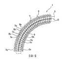
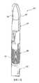
圖1係表示彎曲構造體的剖面圖(實施例1)。Fig. 1 is a cross-sectional view showing a curved structure (Example 1).
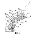
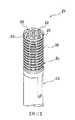
圖2係表示圖1之彎曲構造體局部的放大圖(實施例1)。Fig. 2 is an enlarged view showing part of the curved structure of Fig. 1 (Example 1).
圖3係表示圖1之彎曲構造體的彎曲狀態的剖面圖(實施例1)。Fig. 3 is a cross-sectional view showing a bent state of the bent structure of Fig. 1 (Example 1).
圖4係表示圖3之彎曲構造體局部的放大圖(實施例1)。4 is an enlarged view showing part of the curved structure of FIG. 3 (Example 1).
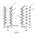
圖5係表示內線圈部由外線圈部脫離的概略剖面圖,其中(A)為脫離前,(B)為脫離後之狀態(實施例1)。5 is a schematic cross-sectional view showing that the inner coil portion is detached from the outer coil portion, where (A) is before detachment and (B) is the state after detachment (Example 1).
圖6(A)係表示比較例之彎曲構造體的剖面圖,(B)係表示比較例之彎曲構造體的彎曲狀態的剖面圖(實施例1)。6(A) is a cross-sectional view showing a curved structure of a comparative example, and (B) is a cross-sectional view showing a curved state of the curved structure of the comparative example (Example 1).
圖7係表示彎曲構造體局部的放大剖面圖(實施例2)。7 is an enlarged cross-sectional view of a part of a curved structure (Example 2).
圖8係表示彎曲構造體局部的放大剖面圖(實施例3)。Fig. 8 is an enlarged cross-sectional view of a part of a curved structure (Example 3).
圖9係表示彎曲構造體的剖面圖(實施例4)。9 is a cross-sectional view showing a curved structure (Example 4).
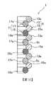
圖10係表示彎曲構造體局部的放大剖面圖(實施例5)。Fig. 10 is an enlarged cross-sectional view showing part of a curved structure (Example 5).
圖11係表示機器人夾鉗局部的立體圖(實施例6)。Fig. 11 is a perspective view showing a part of the robot gripper (Example 6).
圖12係表示圖11之機器人夾鉗的剖面圖(實施例6)。Fig. 12 is a cross-sectional view of the robot gripper of Fig. 11 (Embodiment 6).
圖13係表示圖11之機器人夾鉗的彎曲部的立體圖(實施例6)。Fig. 13 is a perspective view showing a bent portion of the robot gripper of Fig. 11 (Example 6).
圖14係圖13之彎曲部的剖面圖(實施例6)。14 is a cross-sectional view of the bent portion of FIG. 13 (Example 6).
藉由使內部線圈位於外線圈部內之雙重線圈形狀的彎曲構造體,實現謀求彎曲動作的穩定化並簡化構造的目的。The double coil-shaped curved structure in which the inner coil is located in the outer coil portion achieves the purpose of stabilizing the bending operation and simplifying the structure.
亦即,彎曲構造體係可相對於軸方向彎曲,且具備:外線圈部,由捲繞為線圈狀且在軸方向具有多個卷部的線材所構成;以及內線圈部,由捲繞為線圈狀且在軸方向具有多個卷部的線材所構成,該內線圈部位於該外線圈部內。That is, the bending structure system can be bent with respect to the axial direction, and includes: an outer coil portion composed of a wire wound in a coil shape and having a plurality of coil portions in the axial direction; and an inner coil portion composed of a coil wound It is composed of a wire material having a plurality of winding portions in the axial direction, and the inner coil portion is located in the outer coil portion.
外線圈部具有使在軸方向相鄰之卷部間分開的多個間隙,內線圈部中,卷部對應於外線圈部之間隙而設置,且接觸外線圈部的相鄰卷部並嵌合於該等卷部之間。The outer coil portion has a plurality of gaps separating the adjacent coil portions in the axial direction. In the inner coil portion, the coil portion is provided corresponding to the gap of the outer coil portion, and contacts the adjacent coil portions of the outer coil portion and fits Between these volumes.
外線圈部可為在軸方向相鄰的各卷部間具有間隙、或僅在軸方向的一部分具有間隙的構成。The outer coil portion may have a gap between roll portions adjacent in the axial direction, or a gap in only a part of the axial direction.
內線圈部相對於外線圈部軸心在徑方向可移動的可動長度可為外線圈部直徑減去內線圈部直徑後的值的一半以下。The movable length of the inner coil portion with respect to the axis of the outer coil portion in the radial direction may be equal to or less than half the value of the outer coil portion diameter minus the inner coil portion diameter.
此時,可為具有以下限制構件的構成:該限制構件限制內線圈部的移動,以使可動長度成為外線圈部直徑減去內線圈部直徑後的值的一半以下。In this case, it may be configured to include a restricting member that restricts the movement of the inner coil portion so that the movable length is equal to or less than half the value of the outer coil portion diameter minus the inner coil portion diameter.
亦可將限制構件作為可撓曲構件,並將彎曲構造體構成為供可撓曲構件以可在軸方向移動的方式插通,並可與可撓曲構件一起彎曲。The restricting member may be used as a flexible member, and the bending structure may be configured so that the flexible member can be inserted in a manner movable in the axial direction and can be bent together with the flexible member.
又,內線圈部與外線圈部可為分開或可一體地構成。內線圈部與外線圈部形成為不同個體時,可為內線圈部螺合於外線圈部內的構成。In addition, the inner coil portion and the outer coil portion may be separated or may be formed integrally. When the inner coil part and the outer coil part are formed as different individuals, the inner coil part may be screwed into the outer coil part.
應用可撓曲構件之彎曲構造體的關節功能部,可為具備基部及會相對於該基部位移的可動部的構成。此時,彎曲構造體設置於基部與可動部之間,並因應可動部相對於基部的位移而彎曲。The joint function portion of the bending structure using the flexible member may be a structure including a base portion and a movable portion that is displaced relative to the base portion. At this time, the bending structure is provided between the base and the movable portion, and bends in response to the displacement of the movable portion relative to the base.
又,關節功能部亦可具備設置於基部與可動部之間並可在軸方向伸縮的可撓曲管。此時,彎曲構造體沿著可撓曲管的軸心部配置於軸方向。In addition, the joint function portion may include a flexible tube that is provided between the base portion and the movable portion and that can expand and contract in the axial direction. At this time, the curved structure is arranged in the axial direction along the axial center portion of the flexible tube.
(實施例1)(Example 1)
[彎曲構造體之構造][Structure of curved structure]
圖1係表示本發明之實施例1之可撓曲構件的彎曲構造體的剖面圖,圖2係表示其局部的放大圖。FIG. 1 is a cross-sectional view showing a bent structure of a flexible member according to
彎曲構造體1應用於例如各種領域之機器人、機械手臂或致動機構等的關節功能部。該彎曲構造體1設置於關節功能部的基部與可動部之間,並以藉由彎曲而使可動部可相對於基部位移的方式支撐該可動部。The
本實施例的彎曲構造體1為雙重線圈形狀,具備外線圈部5及內線圈部7。藉由該雙重線圈形狀,本實施例的彎曲構造體1可相對於軸方向彎曲,且為以下構成:在藉由外力彎曲時,彎曲的內徑側會收縮且彎曲的外徑側會伸長,藉此,軸方向中心軸或軸心O的長度在彎曲前後及彎曲中幾乎為固定,在不彎曲時則限制往軸方向的壓縮。根據本實施例的彎曲構造體1亦具備作為限制構件的可撓曲構件3。The
可撓曲構件3係可在軸方向移動地插通過彎曲構造體1,詳細如後述,但其限制內外線圈部5、7往徑方向的偏移。本實施例的可撓曲構件3例如利用推拉索等而構成。對應於此,彎曲構造體1具有將可撓曲構件3導引往軸方向的功能,並可因應關節功能部的彎曲動作而與可撓曲構件3一起彎曲。The
又,彎曲是指使關節功能部或彎曲構造體1的軸心O彎折或彎曲。又,亦可省略可撓曲構件3。In addition, bending means bending or bending the axis O of the joint function portion or the bending
外線圈部5為線圈彈簧,由捲繞為線圈狀的線材5a所構成。因此,外線圈部5在軸方向具有多個卷部5b。又,卷部5b意指構成線圈形狀的一個旋圈(以下亦同)。The
線材5a的材質可為金屬或樹脂等。線材5a的剖面可形成為圓形,但也可為楕圓等。The material of the
外線圈部5的中心徑D1在軸方向從一端至另一端成為不變的。但亦可使外線圈部5的中心徑D1在軸方向變化。The center diameter D1 of the
外線圈部5具有使在軸方向相鄰之卷部5b間在軸方向分開的多個間隙5c。本實施例的間隙5c形成於在軸方向相鄰之各卷部5b間,所有間隙5c具有相同的軸方向尺寸。但間隙5c亦可僅設置於軸方向的一部分的卷部5b間。又,亦可改變間隙5c的軸方向尺寸。The
內線圈部7為線圈彈簧,由在軸方向具有多個卷部7b且捲繞為線圈狀的線材7a所構成。內線圈部7與外線圈部相同,線材7a的材質可為金屬或樹脂,線材7a的剖面為圓形,但亦可為楕圓等。The
該內線圈部7位於外線圈部5的內側,並在內周劃分出用以插通可撓曲構件3的插通部9。本實施例的內線圈部7螺合於外線圈部5內。藉由該螺合,內線圈部7的卷部7b位於外線圈部5之各個相鄰卷部5b間。因此,內線圈部7成為以下構成:卷部7b對應於外線圈部5的間隙5c而設置。The
又,藉由設定中心徑D2及線材7a的線徑d2,內線圈部7的卷部7b接觸外線圈部5的相鄰卷部5b,並嵌合於該等卷部5b之間。Further, by setting the center diameter D2 and the wire diameter d2 of the
又,內線圈部7的中心徑D2在軸方向從一端至另一端為不變的。但亦可使內線圈部7的中心徑D2因應外線圈部5的中心徑D1而在軸方向改變。In addition, the center diameter D2 of the
又,線材7a的線徑d2與外線圈部5之線材5a的線徑d1相同。但線材7a的線徑d2亦可形成為大於或小於外線圈部5之線材5a的線徑d1。The wire diameter d2 of the
內線圈部7具有使相鄰卷部7b間在軸方向分開的多個間隙7c。間隙7c因應與外線圈部5的螺合而形成於各個相鄰卷部7b間,所有間隙7c具有相同的軸方向尺寸。The
又,在內部線圈7不位於外線圈部5內之自由狀態下,外線圈部5及內線圈部7除了在各個相鄰卷部5b、7b間具有間隙5c、7c之構成以外,也可為在自由狀態下使相鄰卷部5b、7b密接的構成(密接彈簧)。又,也可僅使外線圈部5及內線圈部7之其中一者為密接彈簧。In addition, in a free state in which the
外線圈部5及內線圈部7在自由狀態下為密接彈簧時,藉由螺合內線圈部7與外線圈部5而相互地使卷部5b、7b間分開,並形成外線圈部5的 間隙5c及內線圈部7的間隙7c。此時,可在雙重線圈形狀的彎曲構造體1施加初張力。When the
[彎曲構造體之動作][Action of bending structure]
圖3係表示圖1之彎曲構造體的彎曲狀態的剖面圖,圖4為表示其局部的放大圖。FIG. 3 is a cross-sectional view showing a curved state of the curved structure of FIG. 1, and FIG. 4 is an enlarged view showing a part of it.
如圖1及圖2所示,彎曲構造體1在軸心O(包括外線圈部5的軸心)未彎曲的直狀時,內線圈部7的卷部7b接觸外線圈部5的相鄰卷部5b,並嵌合於該等相鄰卷部5b之間。As shown in FIGS. 1 and 2, when the
因此,彎曲構造體1即使作用有軸方向的壓縮力,內線圈部7的卷部7b會限制外線圈部5的間隙5c被壓縮,可抑制整體的壓縮。又,若以內線圈部7為基準,則外線圈部5的卷部5b會限制內線圈部7的間隙7c被壓縮。Therefore, even if the compressive force in the axial direction acts on the
因此,彎曲構造體1可抑制本身的壓縮,且可抑制應用之關節功能部的壓縮。其結果,導引可撓曲構件3往軸方向移動時,軸心O的長度以及通過軸心O上之可撓曲構件3的移動量可保持不變,並可確保可撓曲構件3的動作穩定性。Therefore, the bending
如圖3及圖4所示,當彎曲構造體1的軸心O彎曲時,在彎曲的內側的外線圈部5的間隙5c變小,在彎曲的外側的外線圈部5的間隙5c變大。As shown in FIGS. 3 and 4, when the axis O of the
此時,內線圈部7往徑方向外側位移,藉此,彎曲構造體1可順利彎曲。At this time, the
亦即,在彎曲構造體1之彎曲的內側,內線圈部7的各卷部7b藉由外線圈部5的間隙5c變小而被往徑方向內側押入。因應於此,內線圈部7整體往徑方向外側位移,但以內線圈部7的各卷部7b進入外線圈部5變大的間隙5c的方式容許該位移。That is, inside the bend of the
因此,彎曲構造體1為可限制軸方向之壓縮之構成,並且不會阻礙可撓性。其結果,彎曲構造體1可謀求彎曲動作的穩定化。Therefore, the
又,如上述,在彎曲構造體1彎曲時,在彎曲的內側的外線圈部5的間隙5c變小,在彎曲的外側的外線圈部5的間隙變大,故軸心O上的間隙5c大小相較於直狀時沒有變化。Also, as described above, when the
因此,彎曲構造體1不僅是在直狀時,在彎曲時亦使軸心O的長度及通過彎曲構造體1的軸心O上的可撓曲構件3移動量保持為不變,可確保可撓曲構件3的動作穩定性。Therefore, the
又,本實施例之彎曲構造體1彎曲為預定角度時,在彎曲的內側之外線圈部5的相鄰卷部5b會接觸(參照圖4)。In addition, when the
因此,在彎曲構造體1中,自卷部5b接觸時起,軸心O上的長度會開始變大。因此,可藉由可撓曲構件3移動量的變化,而通知關節功能部的操作者已彎曲至預定角度以上。Therefore, in the
在該彎曲構造體1的彎曲動作時,藉由可撓曲構件3而可防止內線圈部7從外線圈部5脫離。During the bending operation of the bending
亦即,如上述,在彎曲構造體1彎曲時,內線圈部7的各卷部7b進入外線圈部5變大的間隙5c,內線圈部7整體往徑方向外側位移。That is, as described above, when the bending
該位移(內線圈部7相對於外線圈部5軸心O可在徑方向移動的可動長度)為外線圈部直徑減去內線圈部直徑後的值的一半以下。又,在此,直徑是指外線圈部7及內線圈部5的中心徑D1及D2。但直徑亦可為外線圈部7及內線圈部5的外徑或內徑。This displacement (movable length of the
圖5為表示內線圈部7從外線圈部5脫離的概略剖面圖,(A)為脫離前,(B)為脫離後的狀態。5 is a schematic cross-sectional view showing that the
如圖5所示,直狀時內線圈部7往徑方向的移動量L若超過外線圈部5直徑減去內線圈部7直徑的一半(D1-D2)/2,則會成為內線圈部7越過外線圈部5並脫離的狀態。又,圖5中,移動量L係表示為內線圈部7軸心與外線圈部5軸心的偏差量。As shown in FIG. 5, when the movement amount L of the
彎曲構造體1彎曲時,若內線圈部7往徑方向的移動量L超過外線圈部5直徑減去內線圈部7直徑的一半(D1-D2)/2,則回到直狀時,結果會變成如圖5所示產生脫離,故本實施例中,內線圈部7相對於外線圈部5軸心O可在徑方向移動之可動長度為外線圈部5直徑減去內線圈部7直徑的一半(D1-D2)/2以下。When the bending
在本實施例中,藉由使可撓曲構件3插通彎曲構造體1而設定該可動長度。如此,在本實施例中,藉由可撓曲構件3可防止內線圈部7從外線圈部5脫離。但在彎曲構造體1未插通可撓曲構件3時,或可撓曲構件3的直徑較 細而無法設定上述可動長度時,可藉由設定外線圈部5及內線圈部7的線徑d1及d2之任一者或兩者而設定可動長度。In this embodiment, the movable length is set by inserting the
[比較例之移動量][Movement of Comparative Example]
圖6(A)為表示比較例之彎曲構造體之剖面圖,圖6(B)為表示該彎曲時之剖面圖。FIG. 6(A) is a cross-sectional view showing a curved structure of a comparative example, and FIG. 6(B) is a cross-sectional view showing the bending.
比較例的彎曲構造體1A為僅由密接彈簧所構成,係可彎曲並會限制壓縮。The bending
該彎曲構造體1A中,在彎曲時,在彎曲的內側卷部1Aa會維持接觸狀態,在彎曲的外側於卷部1Aa間形成間隙。In this
其結果,在彎曲時,即使在彎曲構造體1之彎曲內外的中央部,也會在卷部1Aa間形成間隙1Ab。彎曲構造體1之軸心O的長度及通過軸心O上之可撓曲構件3的移動量會增加該間隙1Ab量。As a result, at the time of bending, a gap 1Ab is formed between the rolled portions 1Aa even in the center portion of the bending
因此,在比較例中,導引可撓曲構件3時,係無法如實施例1所示確保可撓曲構件3的動作穩定性。Therefore, in the comparative example, when the
[實施例1之效果][Effect of Example 1]
如以上說明,本實施例的彎曲構造體1係以使可撓曲構件3可在軸方向移動的方式插通,並可與可撓曲構件3一起彎曲,並具備捲繞為線圈狀且在軸方向具有多個卷部5b的線材5a所構成的外線圈部5、以及捲繞為線圈狀且在軸方向多個卷部7b的線材7a所構成的內線圈部7,該內線圈部7位於外線圈部5內。As described above, the bending
外線圈部5具有使相鄰卷部5b間分開的多個間隙5c,內線圈部7中,卷部7b對應於外線圈部5的間隙5c而設置,接觸外線圈部5的相鄰卷部5b並嵌合於該等相鄰卷部5b之間。The
因此,彎曲構造體構成為使內線圈部位於外線圈部內,故可簡化彎曲構造體1的構造。Therefore, the curved structure is configured such that the inner coil portion is located inside the outer coil portion, so that the structure of the
又,彎曲構造體1即使作用有軸方向的壓縮力,外線圈部5的間隙5c會被壓縮,而限制內線圈部7的卷部7b,可抑制整體的壓縮。因此,彎曲構造體1可確保不使關節功能部壓縮程度之軸方向的剛性。In addition, even if the compressive force in the axial direction is applied to the
又,在彎曲時,在彎曲的內側的外線圈部5的間隙5c變小且內線圈部7位移至彎曲的外側,在彎曲的外側的外線圈部5的間隙變大且容許內線 圈部7的位移,藉此即使確保軸方向的剛性,亦可確保用以與關節功能部一起彎曲的充分可撓性。Also, during bending, the
結果而言,彎曲構造體1可謀求彎曲動作的穩定化並簡化構造,故可確保機器人、機械手臂或致動機構等具有關節功能部之機器之動作的穩定性。As a result, the bending
又,本實施例之彎曲構造體1中,在彎曲的內側的外線圈部5的間隙5c變小,在彎曲的外側的外線圈部5的間隙5c變大,故外線圈部5軸心O中的長度相較於直狀時沒有變化,可確實保持不變之可撓曲構件3的移動量。Also, in the
因此可確保可撓曲構件3的動作穩定性,進而可確保具有關節功能部之機器的動作穩定性。Therefore, the operation stability of the
又,本實施例中,內線圈部7相對於外線圈部5軸心O可在徑方向移動的可動長度(位移量)為外線圈部直徑減去內線圈部直徑後的值的一半以下,故可防止內線圈部7從外線圈部5脫離。Furthermore, in this embodiment, the movable length (displacement amount) of the
又,本實施例中,藉由作為限制構件的可撓曲構件3,而以使可動長度成為外線圈部直徑減去內線圈部直徑後的值的一半以下的方式限制內線圈部7的移動,故可在不會變更內線圈部7及外線圈部5的形狀下容易地防止內線圈部7的脫離。Furthermore, in this embodiment, the
彎曲構造體1係以使可撓曲構件3可在軸方向移動的方式插通,並可與可撓曲構件3一起彎曲,故在導引可撓曲構件3的態樣中,利用可撓曲構件3可防止內線圈部7的脫離。The bending
本實施例中,外線圈部5在軸方向相鄰的各卷部5b之間具有間隙5c,故可順利使彎曲構造體1彎曲。In the present embodiment, since the
本實施例中,內線圈部7與外線圈部5形成為不同個體,並使內線圈部7螺合於外線圈部5內,故組裝容易。又,藉由變更內線圈部7及外線圈部5之任一者或兩者的特性,而可容易地變更彎曲構造體1的特性。In this embodiment, the
又,本實施例的彎曲構造體1彎曲為預定角度時,在彎曲的內側的外線圈部5的相鄰卷部5b會接觸,故可藉由可撓曲構件3移動量的改變,而通知關節功能的操作者已彎曲至預定角度以上。In addition, when the bending
(實施例2)(Example 2)
圖7係表示實施例2之彎曲構造體局部的放大剖面圖。又,實施例2中,對應實施例1的構成係附以相同符號並省略重複說明。7 is an enlarged cross-sectional view showing part of the curved structure of Example 2. FIG. In addition, in the second embodiment, the configuration corresponding to the first embodiment is denoted by the same symbol, and repeated description is omitted.
實施例2的彎曲構造體1中,外線圈部5之線材5a的線徑d1與內線圈部7之線材7a的線徑d2不同。實施例2中,外線圈部5的線徑d1大於內線圈部7的線徑d2。又,外線圈部5的線徑d1亦可小於內線圈部7的線徑d2。In the
如上述,彎曲構造體1中,即使外線圈部5的線徑d1與內線圈部7的線徑d2不同,亦可發揮與實施例1相同的作用功效。又,使線徑d2與線徑d1不同,藉此可調整彎曲構造體1的自由長度或特性。As described above, in the
(實施例3)(Example 3)
圖8係表示實施例3之彎曲構造體局部的放大剖面圖。又,實施例3中,對應實施例1的構成係附以相同符號並省略重複說明。8 is an enlarged cross-sectional view showing part of the curved structure of Example 3. FIG. In addition, in the third embodiment, the configuration corresponding to the first embodiment is denoted by the same symbol, and repeated description is omitted.
實施例3的彎曲構造體1中,在外線圈部5的軸方向的一部分中,內線圈部7的卷部7b接觸外線圈部5的相鄰卷部5b,並嵌合於該等相鄰卷部5b之間。In the
亦即,內線圈部7係以在軸方向中心徑D2(參照圖1)逐漸變小的方式形成。對應於此,如上述,內線圈部7僅在軸方向局部嵌合於外線圈部5的相鄰卷部5b之間。That is, the
又,本實施例中,內線圈部7及外線圈部5分別為密接線圈,隨著內線圈部7的中心徑D2變小,外線圈部5的間隙5c也變小。Moreover, in this embodiment, the
即使如上述構成亦與可發揮與實施例1相同的作用功效。此外,本實施例中,僅在外線圈部5的軸方向的一部分使內線圈部7之卷部7b嵌合於外線圈部5的相鄰卷部5b之間,藉此可調整彎曲構造體1的自由長度或特性。Even with the above configuration, it is possible to exert the same functions and effects as in the first embodiment. In addition, in this embodiment, the
(實施例4)(Example 4)
圖9係表示實施例4之彎曲構造體的剖面圖。又,實施例4中,對應實施例1的構成係附以相同符號並省略重複說明。9 is a cross-sectional view showing a curved structure of Example 4. FIG. In addition, in the fourth embodiment, the configuration corresponding to the first embodiment is denoted by the same symbol, and repeated description is omitted.
實施例4的彎曲構造體1係在軸方向局部設置直徑逐漸增大的擴徑部11。本實施例中,在彎曲構造體1的軸方向一端設置擴徑部11。但擴徑部11亦可設置於彎曲構造體1軸方向的中間部或另一端。The
在擴徑部11中,外線圈部5及內線圈部7的中心徑D1及D2皆逐漸增大,且維持內線圈部7的卷部7b接觸外線圈部5的相鄰卷部5b並嵌合於卷部5b之間的狀態。In the
即使如上述構成亦與可發揮與實施例1相同的作用功效。又,藉由擴徑部11可調整彎曲構造體1的特性。Even with the above configuration, it is possible to exert the same functions and effects as in the first embodiment. In addition, the characteristics of the
(實施例5)(Example 5)
圖10係表示實施例5之彎曲構造體局部的放大剖面圖。又,實施例5中,對應實施例1的構成係附以相同符號並省略重複說明。10 is an enlarged cross-sectional view showing a part of the curved structure of Example 5. FIG. In addition, in the fifth embodiment, the configuration corresponding to the first embodiment is denoted by the same symbol, and repeated description is omitted.
實施例5的彎曲構造體1係分別以兩個線圈部構成外線圈部5及內線圈部7。具體而言,外線圈部5係以第一外線圈部13及第二外線圈部15構成,內線圈部7係以第一內線圈部17及第二內線圈部19構成。The
第一外線圈部13及第二外線圈部15係在軸方向交互設置卷部13a、15a,第一內線圈部17及第二內線圈部19亦在軸方向交互設置卷部17a、19a。The first outer coil portion 13 and the second outer coil portion 15 are alternately provided with the
亦即,外線圈部5中,第一外線圈部13及第二外線圈部15的卷部13a、15a在軸方向相鄰,且在該等相鄰卷部13a、15a間形成間隙5c。That is, in the
內線圈部7之第一內線圈部17的卷部17a及第二內線圈部19之卷部19a分別接觸第一外線圈部13及第二外線圈部15的卷部13a、15a,並嵌合於該等卷部13a、15a之間。The rolled
即使如上述構成亦與可發揮與實施例1相同的作用功效,且可調整彎曲構造體1的特性或自由長度。Even with the above-mentioned configuration, it is possible to exert the same functions and effects as in the first embodiment, and the characteristics or free length of the
又,可變更構成外線圈部5及內線圈部7的線圈部的數目。又,可為外線圈部5及內線圈部7之僅一者以多個線圈部構成。In addition, the number of coil parts constituting the
(實施例6)(Example 6)
圖11係有關本發明的實施例6,為表示應用彎曲構造體之機器人夾鉗局部的立體圖,圖12為該剖面圖,圖13為表示圖11之機器人夾鉗之關節功能部的立體圖,圖14為該剖面圖。又,實施例6中,對應實施例1的構成係附以相同符號並省略重複說明。11 is a perspective view of a part of the sixth embodiment of the present invention, showing a portion of a robot gripper using a bending structure, FIG. 12 is a cross-sectional view, and FIG. 13 is a perspective view showing a joint function part of the robot gripper of FIG. 11, 14 is this sectional view. In addition, in the sixth embodiment, the configuration corresponding to the first embodiment is denoted by the same symbol, and repeated description is omitted.
本實施例的機器人夾鉗21係構成醫療用機械手臂之手術機器人的機械手臂前端。The
又,機器人夾鉗21具有關節功能部之機器的一例。具有關節功能部的機器並不限定於如上述之醫療用機械手臂。亦即,作為具有關節功能部的機器,只要為具有進行彎曲動作的關節功能部,且使可撓曲構件3在軸方向移動並進行動作等者,可為其他領域之機器人、各種機械手臂或致動機構等,並無特別限定。又,醫療用機械手臂的情形亦包括未裝設於手術機器人的內視鏡相機或手動夾鉗等。In addition, the
本實施例的機器人夾鉗21由軸23、關節功能部25及作為外科手術用末端效應器的把持單元27所構成。The
軸23例如形成為圓筒形狀。在軸23內有用以驅動關節功能部25的驅動線29或用以驅動把持單元27之推拉索所構成的可撓曲構件3通過。在軸23前端側中,透過關節功能部25設置有把持單元27。The
關節功能部25具備基部31、可動部33、可撓曲管35以及彎曲構造體1。The
基部31係藉由樹脂或金屬等而形成的圓柱體,並裝設於軸23前端。在基部31中,藉由貫穿孔31a而使驅動線29插通於軸方向,並藉由軸心部的插通孔31b而插通有可撓曲構件3。The
可動部33係藉由樹脂或金屬等而形成的圓柱體,並裝設於後述把持單元27。可動部33固定有驅動線29的前端部。因此,可動部33藉由驅動線29的操作而相對於基部31進行位移,並使把持單元27指向所需方向。可動部33的軸心部設置有插通孔33b,並插通有可撓曲構件3。The
可撓曲管35設置於基部31與可動部33之間,並因應可動部33相對於基部31的位移而彎曲。可撓曲管35在軸方向有驅動線29及可撓曲構件3通過。The
本實施例的可撓曲管35係藉由剖面波狀的管體所構成之波紋管而構成。但可撓曲管35亦可使用線圈彈簧、筒體等,只要是呈現具可撓性的管狀,則無特別限定。The
彎曲構造體1為與實施例1相同之構成。該彎曲構造體1沿著可撓曲管35的軸心部而配置,並設置於基部31與可動部33之間。又,在關節功能部25亦可使用實施例2~5之任一彎曲構造體1。The
在於插通部9插通有可撓曲構件3的狀態下,彎曲構造體1其兩端分別裝設於基部31及可動部33的插通孔31b和33b。藉此,彎曲構造體1相對於基部31以無法在軸方向移動的方式支撐可動部33,並可因應可動部33相對於基部31的位移而與可撓曲構件3一起彎曲。In a state where the
把持單元27以一對握持部37可開閉的方式,相對於關節功能部25的可動部33而被樞軸支撐。該把持單元27與貫穿關節功能部25的可撓曲構件3連接,並以藉由可撓曲構件3的軸方向移動(進退動作)而使握持部37開閉的方式而構成。又,末端效應器不限於把持單元27,例如亦可為剪刀、把持牽開器及持針器等。The
該構成的機器人夾鉗21中,醫師等操作者可藉由使可撓曲構件3進退而進行把持單元27之握持部37的開閉動作。In the
又,藉由操作者拉起任何一條或多條驅動線29,可使關節功能部25彎曲並相對於軸23而使把持單元27指向所需方向。在該狀態下,若使可撓曲構件3進退,可使把持單元27的握持部37進行開閉動作。Also, by the operator pulling up any one or
如實施例1所說明,可撓曲構件3的移動量為不變,故可穩定而正確地進行該開閉動作。As described in the first embodiment, since the amount of movement of the
此外,本實施例中,可發揮與實施例1相同的作用功效。In addition, in this embodiment, the same functions and effects as in
1‧‧‧彎曲構造體1‧‧‧Bending structure
3‧‧‧可撓曲構件3‧‧‧Flexible member
5‧‧‧外線圈部5‧‧‧Outer coil
5a、7a‧‧‧線材5a, 7a‧‧‧wire
5b、7b‧‧‧卷部5b, 7b ‧‧‧ volume
5c、7c‧‧‧間隙5c, 7c‧‧‧ gap
7‧‧‧內線圈部7‧‧‧Inner coil
9‧‧‧插通部9‧‧‧Plug-in Department
D1‧‧‧外線圈部的中心徑D1‧‧‧Center diameter of outer coil
D2‧‧‧內線圈部的中心徑D2‧‧‧Center diameter of inner coil
O‧‧‧軸心O‧‧‧Axis
Claims (11)
Translated fromChineseApplications Claiming Priority (6)
| Application Number | Priority Date | Filing Date | Title |
|---|---|---|---|
| JP2018-152642 | 2018-08-14 | ||
| JP2018152642 | 2018-08-14 | ||
| JP2019017778AJP7491503B2 (en) | 2018-08-14 | 2019-02-04 | Robotic surgical instruments |
| JP2019-017778 | 2019-02-04 | ||
| JP2019-022424 | 2019-02-12 | ||
| JP2019022424AJP7096179B2 (en) | 2018-08-14 | 2019-02-12 | Flexion structure and joint function part using it |
Publications (2)
| Publication Number | Publication Date |
|---|---|
| TW202009117Atrue TW202009117A (en) | 2020-03-01 |
| TWI720570B TWI720570B (en) | 2021-03-01 |
Family
ID=69620872
Family Applications (1)
| Application Number | Title | Priority Date | Filing Date |
|---|---|---|---|
| TW108127626ATWI720570B (en) | 2018-08-14 | 2019-08-02 | Curved structure and joint function part using the structure |
Country Status (6)
| Country | Link |
|---|---|
| US (2) | US12262905B2 (en) |
| EP (2) | EP3838518A4 (en) |
| JP (5) | JP7491503B2 (en) |
| CN (2) | CN112654475A (en) |
| TW (1) | TWI720570B (en) |
| WO (1) | WO2020036085A1 (en) |
Cited By (2)
| Publication number | Priority date | Publication date | Assignee | Title |
|---|---|---|---|---|
| CN112809656A (en)* | 2021-02-08 | 2021-05-18 | 清华大学 | Flexible driving structure, flexible driver and driving system |
| TWI846113B (en)* | 2022-10-28 | 2024-06-21 | 日商日本發條股份有限公司 | Curved structure |
Families Citing this family (12)
| Publication number | Priority date | Publication date | Assignee | Title |
|---|---|---|---|---|
| JP6913775B1 (en)* | 2020-02-13 | 2021-08-04 | 日本発條株式会社 | Flexion structure and joint function |
| JP7538692B2 (en)* | 2020-10-30 | 2024-08-22 | 日本発條株式会社 | Bending operation mechanism |
| JP7587962B2 (en)* | 2020-10-30 | 2024-11-21 | 日本発條株式会社 | Bent Structure |
| JP7506620B2 (en)* | 2021-02-25 | 2024-06-26 | 日本発條株式会社 | Bent structure and current-carrying device |
| JP7657094B2 (en)* | 2021-04-30 | 2025-04-04 | 日本発條株式会社 | Bent Structure |
| JP2023018451A (en)* | 2021-07-27 | 2023-02-08 | 日本発條株式会社 | bending structure |
| JP7701848B2 (en)* | 2021-09-29 | 2025-07-02 | 日本発條株式会社 | bending structure |
| JP7741706B2 (en)* | 2021-11-26 | 2025-09-18 | 日本発條株式会社 | Bent structures and semi-finished products |
| CN114701583B (en)* | 2022-04-18 | 2023-02-24 | 东北大学秦皇岛分校 | Rope-driven flexible double-joint bionic crab and control method |
| CN115005993B (en)* | 2022-05-31 | 2023-09-22 | 四川省肿瘤医院 | Bending mechanism and surgical mechanical arm using same |
| JP2024053399A (en) | 2022-10-03 | 2024-04-15 | 日本発條株式会社 | Bent structure and its semi-finished products |
| WO2024089878A1 (en)* | 2022-10-28 | 2024-05-02 | 日本発條株式会社 | Bending structure |
Family Cites Families (25)
| Publication number | Priority date | Publication date | Assignee | Title |
|---|---|---|---|---|
| DE822044C (en)* | 1949-12-23 | 1951-11-22 | Trippel Hanns | Flexible shaft for torque transmission, especially in motor vehicles |
| JPS5279947U (en)* | 1975-12-12 | 1977-06-15 | ||
| DE69020795T2 (en)* | 1989-05-12 | 1995-11-30 | Machida Endoscope Co Ltd | Curvature control arrangement and the structure of a flexible tube. |
| US5271543A (en)* | 1992-02-07 | 1993-12-21 | Ethicon, Inc. | Surgical anastomosis stapling instrument with flexible support shaft and anvil adjusting mechanism |
| DE4305376C1 (en) | 1993-02-22 | 1994-09-29 | Wolf Gmbh Richard | Medical instrument shaft |
| US5405073A (en)* | 1993-12-06 | 1995-04-11 | Ethicon, Inc. | Flexible support shaft assembly |
| US5465894A (en)* | 1993-12-06 | 1995-11-14 | Ethicon, Inc. | Surgical stapling instrument with articulated stapling head assembly on rotatable and flexible support shaft |
| JPH07213526A (en)* | 1994-02-03 | 1995-08-15 | Res Dev Corp Of Japan | Deflection mechanism of calculus crusher |
| US5904647A (en) | 1996-10-08 | 1999-05-18 | Asahi Kogyo Kabushiki Kaisha | Treatment accessories for an endoscope |
| JP3732911B2 (en)* | 1996-10-08 | 2006-01-11 | ペンタックス株式会社 | Endoscopic treatment tool |
| US5851212A (en)* | 1997-06-11 | 1998-12-22 | Endius Incorporated | Surgical instrument |
| US20020087048A1 (en)* | 1998-02-24 | 2002-07-04 | Brock David L. | Flexible instrument |
| US20030135204A1 (en)* | 2001-02-15 | 2003-07-17 | Endo Via Medical, Inc. | Robotically controlled medical instrument with a flexible section |
| JP2006230635A (en)* | 2005-02-24 | 2006-09-07 | Asahi Intecc Co Ltd | Medical treatment tool |
| US8105350B2 (en) | 2006-05-23 | 2012-01-31 | Cambridge Endoscopic Devices, Inc. | Surgical instrument |
| JP4497379B2 (en)* | 2006-08-23 | 2010-07-07 | 朝日インテック株式会社 | Medical treatment tool |
| JP5148936B2 (en)* | 2006-12-28 | 2013-02-20 | テルモ株式会社 | Guide wire |
| US8080038B2 (en)* | 2007-08-17 | 2011-12-20 | Jmea Corporation | Dynamic stabilization device for spine |
| DE102008015418A1 (en) | 2008-03-20 | 2009-09-24 | Richard Wolf Gmbh | Medical instrument |
| US20090247820A1 (en)* | 2008-03-28 | 2009-10-01 | Olympus Medical Systems Corp. | Treatment instrument for endoscopic use |
| US20110152880A1 (en)* | 2009-12-23 | 2011-06-23 | Hansen Medical, Inc. | Flexible and steerable elongate instruments with torsion control |
| JP5436266B2 (en)* | 2010-02-26 | 2014-03-05 | 朝日インテック株式会社 | Medical coil structure, manufacturing method thereof, medical endoscope formed with medical coil structure, medical treatment instrument, ultrasonic diagnostic medical catheter, and optical interference diagnostic medical catheter |
| WO2014156352A1 (en)* | 2013-03-28 | 2014-10-02 | オリンパス株式会社 | Outer sleeve tube and treatment tool |
| JP6422148B2 (en)* | 2014-05-20 | 2018-11-14 | 国立大学法人電気通信大学 | manipulator |
| JP6043037B1 (en)* | 2015-02-13 | 2016-12-14 | オリンパス株式会社 | manipulator |
- 2019
- 2019-02-04JPJP2019017778Apatent/JP7491503B2/enactiveActive
- 2019-02-12JPJP2019022424Apatent/JP7096179B2/enactiveActive
- 2019-08-02CNCN201980053995.9Apatent/CN112654475A/enactivePending
- 2019-08-02USUS17/268,929patent/US12262905B2/enactiveActive
- 2019-08-02USUS17/268,891patent/US20210307773A1/ennot_activeAbandoned
- 2019-08-02TWTW108127626Apatent/TWI720570B/enactive
- 2019-08-02CNCN201980052744.9Apatent/CN112566759A/enactivePending
- 2019-08-02WOPCT/JP2019/030599patent/WO2020036085A1/ennot_activeCeased
- 2019-08-02EPEP19850396.3Apatent/EP3838518A4/enactivePending
- 2019-08-02EPEP19849797.6Apatent/EP3838517A4/ennot_activeWithdrawn
- 2022
- 2022-06-23JPJP2022101074Apatent/JP7373613B2/enactiveActive
- 2023
- 2023-07-27JPJP2023122868Apatent/JP7472374B2/enactiveActive
- 2024
- 2024-04-10JPJP2024063167Apatent/JP2024086847A/enactivePending
Cited By (3)
| Publication number | Priority date | Publication date | Assignee | Title |
|---|---|---|---|---|
| CN112809656A (en)* | 2021-02-08 | 2021-05-18 | 清华大学 | Flexible driving structure, flexible driver and driving system |
| CN112809656B (en)* | 2021-02-08 | 2022-02-18 | 清华大学 | Flexible drive structure, flexible drive and drive system |
| TWI846113B (en)* | 2022-10-28 | 2024-06-21 | 日商日本發條股份有限公司 | Curved structure |
Also Published As
| Publication number | Publication date |
|---|---|
| JP2023153901A (en) | 2023-10-18 |
| JP7373613B2 (en) | 2023-11-02 |
| JP2024086847A (en) | 2024-06-28 |
| JP7491503B2 (en) | 2024-05-28 |
| CN112566759A (en) | 2021-03-26 |
| EP3838517A4 (en) | 2022-09-14 |
| JP2022125093A (en) | 2022-08-26 |
| EP3838517A1 (en) | 2021-06-23 |
| JP2020026021A (en) | 2020-02-20 |
| WO2020036085A1 (en) | 2020-02-20 |
| EP3838518A4 (en) | 2022-08-10 |
| EP3838518A1 (en) | 2021-06-23 |
| US12262905B2 (en) | 2025-04-01 |
| US20210307773A1 (en) | 2021-10-07 |
| CN112654475A (en) | 2021-04-13 |
| TWI720570B (en) | 2021-03-01 |
| US20230001590A1 (en) | 2023-01-05 |
| JP7472374B2 (en) | 2024-04-22 |
| JP2020026019A (en) | 2020-02-20 |
| JP7096179B2 (en) | 2022-07-05 |
Similar Documents
| Publication | Publication Date | Title |
|---|---|---|
| TWI720570B (en) | Curved structure and joint function part using the structure | |
| US20250195098A1 (en) | Bending structure and joint function part | |
| JP2019034081A (en) | Bending structure of medical manipulator | |
| CN102905631B (en) | Driving force transmission mechanism and arm-and-hand system | |
| US20150080908A1 (en) | Energy balance mechanism for flexure joint | |
| EP4104983B1 (en) | Bending structure and joint function part | |
| JP2019034083A (en) | Flexible tube of medical manipulator and bending structure | |
| US12337468B2 (en) | Joint function unit | |
| WO2023095861A1 (en) | Flexural structure and half-finished product thereof | |
| EP4238723B1 (en) | Bending structural body | |
| JPH04193252A (en) | Endoscope | |
| WO2024135779A1 (en) | Bending structure and surgical tool using same |