TW202009112A - Pry bar - Google Patents
Pry barDownload PDFInfo
- Publication number
- TW202009112A TW202009112ATW107139007ATW107139007ATW202009112ATW 202009112 ATW202009112 ATW 202009112ATW 107139007 ATW107139007 ATW 107139007ATW 107139007 ATW107139007 ATW 107139007ATW 202009112 ATW202009112 ATW 202009112A
- Authority
- TW
- Taiwan
- Prior art keywords
- middle section
- head
- section
- angle
- virtual extension
- Prior art date
Links
- 238000005452bendingMethods0.000claimsdescription6
- 230000002093peripheral effectEffects0.000claimsdescription3
- 238000010586diagramMethods0.000description4
- 230000000694effectsEffects0.000description1
- 238000005516engineering processMethods0.000description1
- 230000004048modificationEffects0.000description1
- 238000012986modificationMethods0.000description1
Images


Landscapes
- Orthopedics, Nursing, And Contraception (AREA)
- Prostheses (AREA)
Abstract
Description
Translated fromChinese本發明主要係揭示一種撬桿,尤指容易深入角落的撬桿。The invention mainly discloses a pry bar, especially a pry bar that can easily penetrate into corners.
請參閱我國專利第492908號之「調角撬把改良結構」專利案,其為一種調角撬拔改良,其主係為袪除習用撬拔受工作空間有限的情況下,無法操作之缺失,乃在手柄上設有一凹槽,且在該凹槽中裝設一樞接於手柄之定位壓板且受彈簧所頂持,且在手柄之突耳樞接一撬頭,該撬頭之樞接部表面周緣處配合該定位壓板之壓制部乃設有數個定位槽,因此,當工作區間受限制時,係可按壓該定位壓板,使得定位壓板之壓制部脫離於撬頭之定位槽,即可調整該撬頭之角度,再釋放定位壓板時,即可使得調整後之角度得以定位。Please refer to China Patent No. 492908 "The Angle Adjustable Crowbar Improved Structure" patent case, which is an improved angle adjustable pry pull, its main part is the removal of the conventional pry pull under the circumstances of limited working space, the lack of operation, A groove is provided on the handle, and a positioning pressure plate pivotally connected to the handle is held in the groove and held by the spring, and a prying head is pivotally connected to the lug of the handle, and the prying head is pivotally connected There are several positioning grooves on the pressing part of the peripheral surface of the part that cooperates with the positioning pressure plate. Therefore, when the working area is limited, the positioning pressure plate can be pressed, so that the pressing portion of the positioning pressure plate is separated from the positioning groove of the prying head. When the angle of the prying head is adjusted, and then the positioning pressure plate is released, the adjusted angle can be positioned.
傳統固定角度的撬把為產生大幅度的撬拔行程,其撬頭與手柄之間的夾角會形成90度甚至小於90度的角度,導致撬把不容易插進狹縫處,進而產生調角撬把,然而,在撬把設置可調角度的結構會導致體積增加,且撬把撬頭與握柄之間的角度是透過凹凸配合卡合定位,受力過大會導致卡合關係脫離,結構強度弱。The traditional fixed-angle pry bar produces a large prying stroke, and the angle between the pry head and the handle will form an angle of 90 degrees or less than 90 degrees, causing the pry bar to be difficult to insert into the slit, resulting in angle adjustment Crowbar, however, the structure with adjustable angle on the crowbar will increase the volume, and the angle between the crowbar and the grip is positioned through the concave-convex engagement, excessive force will cause the engagement relationship to disengage, the structure Weak.
有鑑於上述習知結構之缺失,本發明人乃設計出一種撬桿,其係可克服上述習知結構之所有缺點。In view of the lack of the above-mentioned conventional structure, the inventor has designed a pry bar, which can overcome all the disadvantages of the above-mentioned conventional structure.
本發明撬桿其主要目的在於,提供一種包括有一個頭部及一個桿部的撬桿,該桿部連接於該頭部,該桿部設置有一個中段及一個握持段,該中段設置於該頭部與該握持段之間,該中段鄰近該頭部一端至該中段鄰近該握持段一端的連線形成一個第一虛擬延伸線,該握持段鄰近該中段一端至該握持段相異於該中段一端的連線形成一個第二虛擬延伸線,該第一虛擬延伸線與該第二虛擬延伸線之間形成一個第一夾角,該第一夾角位於該第一虛擬延伸線相異於該頭部的一側且位於該第二虛擬延伸線相異於該中段的一側,該第一夾角的角度為10度以上且為80度以下,該撬桿透過上述結構而容易深入角落處。The main purpose of the pry bar of the present invention is to provide a pry bar including a head and a rod portion, the rod portion is connected to the head, the rod portion is provided with a middle section and a grip section, the middle section is provided in A first virtual extension line is formed between the head and the holding section, a line connecting the middle section adjacent to the head to the middle section adjacent to the holding section, and the holding section is adjacent to the middle section to the holding section The segment is different from the connecting line at one end of the middle segment to form a second virtual extension line, a first angle is formed between the first virtual extension line and the second virtual extension line, and the first angle is located on the first virtual extension line Different from the side of the head and located on the side of the second virtual extension line that is different from the middle section, the angle of the first included angle is 10 degrees or more and 80 degrees or less, the pry bar is easy to pass through the above structure Go deep into the corner.
該握持段由鄰近該中段一端至該握持段相異於該中段一端之間設置有一個彎曲部,該彎曲部呈彎曲狀且曲率中心位於該握持段相異於該第一夾角的一側。A bending portion is provided between the end of the holding section and the end of the holding section different from the middle section, the bending section is curved and the center of curvature is located at the holding section different from the first included angle Side.
該第一夾角的角度為34度。The angle of the first included angle is 34 degrees.
該頭部相異於該中段一端至該頭部鄰近該中段一端的連線形成一個第三虛擬延伸線,該第二虛擬延伸線與該第三虛擬延伸線之間形成一個第二夾角,該第二夾角位於該第一虛擬延伸線鄰近該頭部的一側且位於該第三虛擬延伸線鄰近該中段的一側,該第二夾角的角度為70度以上且為110度以下。The head is different from the line from the end of the middle section to the end of the head adjacent to the middle section to form a third virtual extension line, and a second angle is formed between the second virtual extension line and the third virtual extension line, the The second angle is located on the side of the first virtual extension line adjacent to the head and on the side of the third virtual extension line adjacent to the middle section. The angle of the second angle is more than 70 degrees and less than 110 degrees.
該第二夾角的角度為90度。The angle of the second included angle is 90 degrees.
該桿部以一體成形結構固定連接於該頭部,該中段與該握持段之間設置有一個轉折段,該第一夾角鄰近該轉折段。The rod portion is fixedly connected to the head with an integrally formed structure, a turning section is provided between the middle section and the holding section, and the first included angle is adjacent to the turning section.
該中段相異於該頭部一側的外周緣設置有一個背面,該背面呈平面狀。The middle section is different from the outer peripheral edge of the head side and is provided with a back surface, which is planar.
該中段鄰近該頭部一側的外周緣設置有一個前面,該前面至該背面的距離形成一個厚度,該中段設置有一個第一側及一個相反於該第一側的第二側,該第一側至該第二側的距離形成一個寬度,該厚度為該寬度的1.5倍以上至2.5倍以下。The middle section is provided with a front face adjacent to the outer periphery of the head side, and the distance from the front face to the back face forms a thickness. The middle section is provided with a first side and a second side opposite to the first side, the first The distance from one side to the second side forms a width, and the thickness is from 1.5 times to 2.5 times the width.
其他目的、優點和本發明之新穎性將從以下詳細的描述與相關的附圖更加明顯。Other objects, advantages and novelty of the present invention will be more apparent from the following detailed description and related drawings.
有關本發明所採用之技術、手段及其功效,茲舉一較佳實施例並配合圖式詳述如後,此僅供說明之用,在專利申請上並不受此種結構之限制。Regarding the technology, means and effects adopted by the present invention, a preferred embodiment is described in detail in conjunction with the drawings as follows. This is for illustrative purposes only, and is not limited by this structure in the patent application.
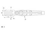
參照圖1至圖4所示,為本發明撬桿之立體外觀圖、平面外觀圖、中段之剖面結構圖及使用狀態圖。本發明撬桿10包括有一個頭部20及一個桿部30:Referring to FIGS. 1 to 4, it is a three-dimensional appearance view, a plan appearance view, a cross-sectional structure diagram and a use state diagram of a pry bar of the present invention. The
該桿部30連接於該頭部20,該桿部30在本實施例中以一體成形結構固定連接於該頭部20。該桿部30設置有一個中段31及一個握持段32,該中段31設置於該頭部20與該握持段32之間,該中段31與該握持段32之間設置有一個轉折段33,該中段31鄰近該頭部20一端至該中段31鄰近該握持段32一端的連線形成一個第一虛擬延伸線L1,該握持段32鄰近該中段31一端至該握持段32相異於該中段31一端的連線形成一個第二虛擬延伸線L2,該第一虛擬延伸線L1與該第二虛擬延伸線L2之間形成一個第一夾角A1,該第一夾角A1鄰近該轉折段33,該第一夾角A1位於該第一虛擬延伸線L1相異於該頭部20的一側且位於該第二虛擬延伸線L2相異於該中段31的一側,該第一夾角A1的角度為10度以上且為80度以下,該第一夾角A1在本實施例中的角度為34度。The
該頭部20相異於該中段31一端至該頭部20鄰近該中段31一端的連線形成一個第三虛擬延伸線L3,該第二虛擬延伸線L2與該第三虛擬延伸線L3之間形成一個第二夾角A2,該第二夾角A2位於該第一虛擬延伸線L1鄰近該頭部20的一側且位於該第三虛擬延伸線L3鄰近該中段31的一側,該第二夾角A2的角度為70度以上且為110度以下,該第二夾角A2在本實施例中的角度為90度。The
該中段31相異於該頭部20一側的外周緣設置有一個背面34,該背面34呈平面狀。該中段31鄰近該頭部20一側的外周緣設置有一個前面35,該前面35至該背面34的距離形成一個厚度T,該中段31設置有一個第一側36及一個相反於該第一側36的第二側37,該第一側36至該第二側37的距離形成一個寬度W,該厚度T為該寬度W的1.5倍以上至2.5倍以下。A
該握持段32由鄰近該中段31一端至該握持段32相異於該中段31一端之間設置有一個彎曲部38,該彎曲部38呈彎曲狀且曲率中心位於該握持段32相異於該第一夾角A1的一側。A
該撬桿10透過上述結構而容易深入角落處,能夠撬起位於角落的釘子,且因該握持段32相較於傳統撬桿的握柄較往後彎,在該撬桿10後方操作的使用者能夠更加容易看到該頭部20的狀態。該撬桿10相較於傳統可變角度之撬桿,體積小且結構強度高。The
就以上所述可以歸納出本發明具有以下優點:Based on the above, the present invention has the following advantages:
1.為本發明撬桿,其中撬桿包括有一個頭部及一個桿部,該桿部連接於該頭部,該桿部設置有一個中段及一個握持段,該中段設置於該頭部與該握持段之間,該中段鄰近該頭部一端至該中段鄰近該握持段一端的連線形成一個第一虛擬延伸線,該握持段鄰近該中段一端至該握持段相異於該中段一端的連線形成一個第二虛擬延伸線,該第一虛擬延伸線與該第二虛擬延伸線之間形成一個第一夾角,該第一夾角位於該第一虛擬延伸線相異於該頭部的一側且位於該第二虛擬延伸線相異於該中段的一側,該第一夾角的角度為10度以上且為80度以下,該撬桿透過上述結構而容易深入角落處。1. The pry bar of the present invention, wherein the pry bar includes a head and a rod portion, the rod portion is connected to the head, the rod portion is provided with a middle section and a grip section, the middle section is provided on the head A connection line between the middle section adjacent to the head and the middle section adjacent to the holding section forms a first virtual extension line between the holding section and the holding section adjacent to the middle section to the holding section A connection line at one end of the middle section forms a second virtual extension line, and a first angle is formed between the first virtual extension line and the second virtual extension line, and the first angle is different from the first virtual extension line The side of the head and the second virtual extension line are different from the side of the middle section, the angle of the first included angle is more than 10 degrees and less than 80 degrees, the pry bar easily penetrates into the corner through the above structure .
惟上所述者,僅為本發明之較佳實施例而已,當不能以之限定本發明實施之範圍,故舉凡數值之變更或等效元件之置換,或依本發明申請專利範圍所作之均等變化與修飾,皆應仍屬本發明專利涵蓋之範疇。However, the above are only preferred embodiments of the present invention, and should not be used to limit the scope of implementation of the present invention, so any change in value or replacement of equivalent elements, or equivalent made in accordance with the scope of patent application of the present invention Changes and modifications should still fall within the scope of this invention patent.
10‧‧‧撬桿20‧‧‧頭部30‧‧‧桿部31‧‧‧中段32‧‧‧握持段33‧‧‧轉折段34‧‧‧背面35‧‧‧前面36‧‧‧第一側37‧‧‧第二側38‧‧‧彎曲部A1‧‧‧第一夾角A2‧‧‧第二夾角L1‧‧‧第一虛擬延伸線L2‧‧‧第二虛擬延伸線L3‧‧‧第三虛擬延伸線T‧‧‧厚度W‧‧‧寬度10‧‧‧Pry
圖1:為本發明撬桿之立體外觀圖。 圖2:為本發明撬桿之平面外觀圖。 圖3:為本發明撬桿中段之剖面結構圖。 圖4:為本發明撬桿之使用狀態圖。Figure 1: The perspective appearance of the pry bar of the present invention. Figure 2: The plan appearance of the pry bar of the present invention. Figure 3: The cross-sectional structure diagram of the middle section of the pry bar of the invention. Figure 4: The use state diagram of the pry bar of the present invention.
10‧‧‧撬桿10‧‧‧Pry bar
20‧‧‧頭部20‧‧‧Head
30‧‧‧桿部30‧‧‧Pole
31‧‧‧中段31‧‧‧ Middle
32‧‧‧握持段32‧‧‧grip
33‧‧‧轉折段33‧‧‧ turning point
34‧‧‧背面34‧‧‧Back
Claims (8)
Translated fromChineseApplications Claiming Priority (3)
| Application Number | Priority Date | Filing Date | Title |
|---|---|---|---|
| ??107128127 | 2018-08-13 | ||
| TW107128127 | 2018-08-13 | ||
| TW107128127 | 2018-08-13 |
Publications (2)
| Publication Number | Publication Date |
|---|---|
| TWI664060B TWI664060B (en) | 2019-07-01 |
| TW202009112Atrue TW202009112A (en) | 2020-03-01 |
Family
ID=68049408
Family Applications (1)
| Application Number | Title | Priority Date | Filing Date |
|---|---|---|---|
| TW107139007ATWI664060B (en) | 2018-08-13 | 2018-11-02 | Pry bar |
Country Status (1)
| Country | Link |
|---|---|
| TW (1) | TWI664060B (en) |
Families Citing this family (3)
| Publication number | Priority date | Publication date | Assignee | Title |
|---|---|---|---|---|
| TWI727611B (en)* | 2020-01-16 | 2021-05-11 | 唐州工業股份有限公司 | Pry tool |
| US20240079837A1 (en)* | 2022-09-02 | 2024-03-07 | Joe Bingham | Universal tool for solar pv module electrical connectors |
| TWI848803B (en)* | 2023-08-25 | 2024-07-11 | 永益年企業股份有限公司 | Crowbar for pulling a plastic nail |
Family Cites Families (4)
| Publication number | Priority date | Publication date | Assignee | Title |
|---|---|---|---|---|
| US6752380B1 (en)* | 2003-02-12 | 2004-06-22 | Dasco Pro, Inc. | Pry bar |
| US8365332B2 (en)* | 2008-11-07 | 2013-02-05 | Milwaukee Electric Tool Corporation | Utility bar |
| CN204686823U (en)* | 2015-03-26 | 2015-10-07 | 钟凯宏 | A kind of nail extractor |
| CN205111777U (en)* | 2015-11-26 | 2016-03-30 | 杭州巨星科技股份有限公司 | Take magnet steel lever |
- 2018
- 2018-11-02TWTW107139007Apatent/TWI664060B/ennot_activeIP Right Cessation
Also Published As
| Publication number | Publication date |
|---|---|
| TWI664060B (en) | 2019-07-01 |
Similar Documents
| Publication | Publication Date | Title |
|---|---|---|
| USD936854S1 (en) | Sex toy | |
| USD1050084S1 (en) | Pair of earphones | |
| TW202009112A (en) | Pry bar | |
| USD867755S1 (en) | Handbag | |
| USD942640S1 (en) | Microtome | |
| USD944645S1 (en) | Cap | |
| USD979483S1 (en) | Canopy | |
| USD905963S1 (en) | Fashion ornament for a handbag | |
| USD916376S1 (en) | Eye shadow case | |
| USD879571S1 (en) | Pliers with a grommet-style fulcrum | |
| USD914986S1 (en) | Eye shadow case | |
| USD972326S1 (en) | Chair | |
| US20160091732A1 (en) | Eyewear temple | |
| USD933558S1 (en) | Pair of tailpipes | |
| USD919117S1 (en) | Building | |
| USD989045S1 (en) | Earphone | |
| USD954682S1 (en) | Wireless earphone | |
| USD907980S1 (en) | Conduit bender | |
| USD1011548S1 (en) | Sex toy | |
| USD825305S1 (en) | Power tool handle portion | |
| USD972327S1 (en) | Chair | |
| USD990880S1 (en) | Suitcase | |
| TWD203853S (en) | Scissor | |
| USD987740S1 (en) | Inflatable penguin | |
| CN204157905U (en) | A brush structure for easy replacement of brush heads |
Legal Events
| Date | Code | Title | Description |
|---|---|---|---|
| MM4A | Annulment or lapse of patent due to non-payment of fees |