TW202003060A - Winged needle hub and internal fistula needle set using same - Google Patents
Winged needle hub and internal fistula needle set using sameDownload PDFInfo
- Publication number
- TW202003060A TW202003060ATW107119193ATW107119193ATW202003060ATW 202003060 ATW202003060 ATW 202003060ATW 107119193 ATW107119193 ATW 107119193ATW 107119193 ATW107119193 ATW 107119193ATW 202003060 ATW202003060 ATW 202003060A
- Authority
- TW
- Taiwan
- Prior art keywords
- needle
- cover
- wall
- wing
- catheter
- Prior art date
Links
- 206010016717FistulaDiseases0.000titleabstract2
- 230000003890fistulaEffects0.000titleabstract2
- 230000001681protective effectEffects0.000claimsabstractdescription31
- 239000013013elastic materialSubstances0.000claimsabstractdescription4
- 230000002093peripheral effectEffects0.000claimsdescription7
- 238000001802infusionMethods0.000claimsdescription6
- 239000000853adhesiveSubstances0.000claimsdescription2
- 230000001070adhesive effectEffects0.000claimsdescription2
- 239000008280bloodSubstances0.000abstractdescription6
- 210000004369bloodAnatomy0.000abstractdescription6
- 239000003814drugSubstances0.000abstractdescription4
- 238000002347injectionMethods0.000description9
- 239000007924injectionSubstances0.000description9
- 238000000034methodMethods0.000description7
- 238000000465mouldingMethods0.000description4
- 230000000694effectsEffects0.000description2
- 238000005516engineering processMethods0.000description2
- 238000001746injection mouldingMethods0.000description2
- 238000004519manufacturing processMethods0.000description2
- 239000002390adhesive tapeSubstances0.000description1
- 229940079593drugDrugs0.000description1
- 239000012530fluidSubstances0.000description1
- 238000003780insertionMethods0.000description1
- 230000037431insertionEffects0.000description1
- 239000002184metalSubstances0.000description1
- 238000000926separation methodMethods0.000description1
Images


Classifications
- A—HUMAN NECESSITIES
- A61—MEDICAL OR VETERINARY SCIENCE; HYGIENE
- A61M—DEVICES FOR INTRODUCING MEDIA INTO, OR ONTO, THE BODY; DEVICES FOR TRANSDUCING BODY MEDIA OR FOR TAKING MEDIA FROM THE BODY; DEVICES FOR PRODUCING OR ENDING SLEEP OR STUPOR
- A61M25/00—Catheters; Hollow probes
- A61M25/01—Introducing, guiding, advancing, emplacing or holding catheters
- A61M25/06—Body-piercing guide needles or the like
- A61M25/0612—Devices for protecting the needle; Devices to help insertion of the needle, e.g. wings or holders
- A61M25/0637—Butterfly or winged devices, e.g. for facilitating handling or for attachment to the skin
- A—HUMAN NECESSITIES
- A61—MEDICAL OR VETERINARY SCIENCE; HYGIENE
- A61B—DIAGNOSIS; SURGERY; IDENTIFICATION
- A61B5/00—Measuring for diagnostic purposes; Identification of persons
- A61B5/15—Devices for taking samples of blood
- A61B5/150007—Details
- A61B5/150015—Source of blood
- A61B5/15003—Source of blood for venous or arterial blood
- A—HUMAN NECESSITIES
- A61—MEDICAL OR VETERINARY SCIENCE; HYGIENE
- A61B—DIAGNOSIS; SURGERY; IDENTIFICATION
- A61B5/00—Measuring for diagnostic purposes; Identification of persons
- A61B5/15—Devices for taking samples of blood
- A61B5/150007—Details
- A61B5/150374—Details of piercing elements or protective means for preventing accidental injuries by such piercing elements
- A61B5/150534—Design of protective means for piercing elements for preventing accidental needle sticks, e.g. shields, caps, protectors, axially extensible sleeves, pivotable protective sleeves
- A61B5/150541—Breakable protectors, e.g. caps, shields or sleeves, i.e. protectors separated destructively, e.g. by breaking a connecting area
- A61B5/150564—Protectors removed by pulling or pushing
- A—HUMAN NECESSITIES
- A61—MEDICAL OR VETERINARY SCIENCE; HYGIENE
- A61B—DIAGNOSIS; SURGERY; IDENTIFICATION
- A61B5/00—Measuring for diagnostic purposes; Identification of persons
- A61B5/15—Devices for taking samples of blood
- A61B5/150007—Details
- A61B5/150374—Details of piercing elements or protective means for preventing accidental injuries by such piercing elements
- A61B5/150534—Design of protective means for piercing elements for preventing accidental needle sticks, e.g. shields, caps, protectors, axially extensible sleeves, pivotable protective sleeves
- A61B5/150572—Pierceable protectors, e.g. shields, caps, sleeves or films, e.g. for hygienic purposes
- A—HUMAN NECESSITIES
- A61—MEDICAL OR VETERINARY SCIENCE; HYGIENE
- A61B—DIAGNOSIS; SURGERY; IDENTIFICATION
- A61B5/00—Measuring for diagnostic purposes; Identification of persons
- A61B5/15—Devices for taking samples of blood
- A61B5/150007—Details
- A61B5/150374—Details of piercing elements or protective means for preventing accidental injuries by such piercing elements
- A61B5/150534—Design of protective means for piercing elements for preventing accidental needle sticks, e.g. shields, caps, protectors, axially extensible sleeves, pivotable protective sleeves
- A61B5/150664—Pivotable protective sleeves, i.e. sleeves connected to, or integrated in, the piercing or driving device, and which are pivoted for covering or uncovering the piercing element
- A—HUMAN NECESSITIES
- A61—MEDICAL OR VETERINARY SCIENCE; HYGIENE
- A61B—DIAGNOSIS; SURGERY; IDENTIFICATION
- A61B5/00—Measuring for diagnostic purposes; Identification of persons
- A61B5/15—Devices for taking samples of blood
- A61B5/150007—Details
- A61B5/150374—Details of piercing elements or protective means for preventing accidental injuries by such piercing elements
- A61B5/150534—Design of protective means for piercing elements for preventing accidental needle sticks, e.g. shields, caps, protectors, axially extensible sleeves, pivotable protective sleeves
- A61B5/150694—Procedure for removing protection means at the time of piercing
- A61B5/150717—Procedure for removing protection means at the time of piercing manually removed
- A—HUMAN NECESSITIES
- A61—MEDICAL OR VETERINARY SCIENCE; HYGIENE
- A61B—DIAGNOSIS; SURGERY; IDENTIFICATION
- A61B5/00—Measuring for diagnostic purposes; Identification of persons
- A61B5/15—Devices for taking samples of blood
- A61B5/153—Devices specially adapted for taking samples of venous or arterial blood, e.g. with syringes
- A—HUMAN NECESSITIES
- A61—MEDICAL OR VETERINARY SCIENCE; HYGIENE
- A61M—DEVICES FOR INTRODUCING MEDIA INTO, OR ONTO, THE BODY; DEVICES FOR TRANSDUCING BODY MEDIA OR FOR TAKING MEDIA FROM THE BODY; DEVICES FOR PRODUCING OR ENDING SLEEP OR STUPOR
- A61M25/00—Catheters; Hollow probes
- A61M25/01—Introducing, guiding, advancing, emplacing or holding catheters
- A61M25/06—Body-piercing guide needles or the like
- A61M25/0612—Devices for protecting the needle; Devices to help insertion of the needle, e.g. wings or holders
- A61M25/0618—Devices for protecting the needle; Devices to help insertion of the needle, e.g. wings or holders having means for protecting only the distal tip of the needle, e.g. a needle guard
- A—HUMAN NECESSITIES
- A61—MEDICAL OR VETERINARY SCIENCE; HYGIENE
- A61M—DEVICES FOR INTRODUCING MEDIA INTO, OR ONTO, THE BODY; DEVICES FOR TRANSDUCING BODY MEDIA OR FOR TAKING MEDIA FROM THE BODY; DEVICES FOR PRODUCING OR ENDING SLEEP OR STUPOR
- A61M39/00—Tubes, tube connectors, tube couplings, valves, access sites or the like, specially adapted for medical use
- A61M39/10—Tube connectors; Tube couplings
- A—HUMAN NECESSITIES
- A61—MEDICAL OR VETERINARY SCIENCE; HYGIENE
- A61M—DEVICES FOR INTRODUCING MEDIA INTO, OR ONTO, THE BODY; DEVICES FOR TRANSDUCING BODY MEDIA OR FOR TAKING MEDIA FROM THE BODY; DEVICES FOR PRODUCING OR ENDING SLEEP OR STUPOR
- A61M5/00—Devices for bringing media into the body in a subcutaneous, intra-vascular or intramuscular way; Accessories therefor, e.g. filling or cleaning devices, arm-rests
- A61M5/14—Infusion devices, e.g. infusing by gravity; Blood infusion; Accessories therefor
- A61M5/158—Needles for infusions; Accessories therefor, e.g. for inserting infusion needles, or for holding them on the body
- A61M2005/1586—Holding accessories for holding infusion needles on the body
- A—HUMAN NECESSITIES
- A61—MEDICAL OR VETERINARY SCIENCE; HYGIENE
- A61M—DEVICES FOR INTRODUCING MEDIA INTO, OR ONTO, THE BODY; DEVICES FOR TRANSDUCING BODY MEDIA OR FOR TAKING MEDIA FROM THE BODY; DEVICES FOR PRODUCING OR ENDING SLEEP OR STUPOR
- A61M25/00—Catheters; Hollow probes
- A61M25/0097—Catheters; Hollow probes characterised by the hub
Landscapes
- Health & Medical Sciences (AREA)
- Life Sciences & Earth Sciences (AREA)
- Heart & Thoracic Surgery (AREA)
- Animal Behavior & Ethology (AREA)
- Hematology (AREA)
- Engineering & Computer Science (AREA)
- Biomedical Technology (AREA)
- Veterinary Medicine (AREA)
- Public Health (AREA)
- General Health & Medical Sciences (AREA)
- Biophysics (AREA)
- Anesthesiology (AREA)
- Pathology (AREA)
- Surgery (AREA)
- Molecular Biology (AREA)
- Medical Informatics (AREA)
- Physics & Mathematics (AREA)
- Pulmonology (AREA)
- Vascular Medicine (AREA)
- Infusion, Injection, And Reservoir Apparatuses (AREA)
Abstract
Description
Translated fromChinese本發明與內廔管翼狀針有關,特別是指一種用於內廔管翼狀針之針座及使用該針座之內廔管翼狀針。The invention relates to an inner tube wing needle, in particular to a needle holder for an inner tube wing needle and an inner tube wing needle using the needle holder.
內廔管翼狀針在結構上有別於一般注射針,其主要在跟針體連接之導管的兩相對側分別設置一翼片,該二翼片一方面用來讓操作人員方便握持以順利完成注射動作,另一方面用來黏貼於皮膚上以穩定針體的位置,使藥劑能夠輸送至人體內,或者是將血液從人體內抽出。The inner tube wing needle is different from the general injection needle in structure. It is mainly provided with a wing piece on the two opposite sides of the catheter connected to the needle body. The two wing pieces are used to facilitate the operator to hold it smoothly Completing the injection action, on the other hand, it is used to stick to the skin to stabilize the position of the needle body, so that the drug can be delivered into the human body, or the blood is drawn from the human body.
為了確保針體在使用前不會受到損壞及在使用過後不會刺傷操作人員的手指,在結構上會搭配一護蓋將針體給套住,當要進行注射時,先將護蓋打開,才能將針體插入人體欲注射的部位,當完成注射且將針體抽出時,需要將原本取下的護蓋重新套上以防止針體外露。就與護蓋相關的先前技術來說,如中華民國公告第M488318號專利案、中華民國公告第M494001號專利案及中華民國公告第M496494號專利案等,前述各專利案所揭露的護蓋不僅在結構上較為複雜,而且必須另外跟針座進行組裝才能夠使用,如此在組裝過程當中仍有可能發生被針體意外刺傷的風險。In order to ensure that the needle body will not be damaged before use and will not stab the operator's fingers after use, the structure will be matched with a protective cover to cover the needle body. When the injection is to be performed, first open the protective cover, In order to insert the needle body into the part of the body to be injected, when the injection is completed and the needle body is withdrawn, the protective cover that was originally removed needs to be put on again to prevent the needle body from being exposed. Regarding the prior art related to the cover, such as the Patent Case No. M488318 published by the Republic of China, the Patent Case No. M494001 published by the Republic of China, and the Patent Case No. M496494 issued by the Republic of China, etc. The structure is more complicated, and it must be assembled with the needle holder before it can be used. In this way, the risk of accidental puncture by the needle body may occur during the assembly process.
本發明之主要目的在於提供一種用於內廔管翼狀針之針座,其能簡化結構、操作方便,以及增加收針安全性。The main object of the present invention is to provide a needle seat for an inner tube wing needle, which can simplify the structure, facilitate operation, and increase the safety of needle closing.
為了達成上述主要目的,本發明之針座包含有一導管、二翼片及一護蓋。該導管具有一前端與一後端;該二翼片一體地連接於該導管之兩相對側;該護蓋具有一容針槽,且該護蓋一體地連接於該導管之前端,使得該護蓋能相對該導管於一開放位置與一蓋合位置之間彈性擺動,當該護蓋位於該開放位置時,該導管之一中心軸線不會通過該護蓋之容針槽,此時固定於該導管之一針體會完全顯露在外,以便進行注射或抽血動作,當該護蓋位於該蓋合位置時,該導管之中心軸線通過該護蓋之容針槽,此時該針體會被該護蓋所遮蓋住,以避免該針體意外刺傷操作人員。In order to achieve the above main objective, the needle holder of the present invention includes a catheter, two wings and a cover. The catheter has a front end and a rear end; the two wings are integrally connected to two opposite sides of the catheter; the protective cover has a needle-receiving groove, and the protective cover is integrally connected to the front end of the catheter, so that the protective The cover can elastically swing between an open position and a closed position relative to the catheter. When the protective cover is in the open position, one of the central axes of the catheter will not pass through the needle-receiving slot of the protective cover and is fixed at One of the needle bodies of the catheter will be completely exposed for injection or blood drawing. When the protective cover is in the closed position, the central axis of the catheter passes through the needle-receiving groove of the protective cover. The cover is covered to prevent the needle from accidentally puncturing the operator.
由上述可知,本發明之針座是用一體成型的方式所製成,相較於習用技術所採用的分離式設計,不但有效地簡化結構及降低製造成本,在操作上也只需要一根手指即可將該護蓋從該針體之一側推動至將該針體完全收納為止,進而大幅減少手部與該針體接觸的機會,以達到增加操作便利性及提升收針安全性的目的。It can be seen from the above that the needle holder of the present invention is made by an integral molding method. Compared with the separated design adopted by the conventional technology, it not only effectively simplifies the structure and reduces the manufacturing cost, but also requires only one finger for operation You can push the cover from one side of the needle body until the needle body is completely stored, thereby greatly reducing the chance of the hand coming into contact with the needle body, so as to increase the convenience of operation and improve the safety of needle withdrawal .
更佳地,其中一該翼片之頂面具有一定位凸部,另外一該翼片之頂面具有一定位凹部,當該二翼片之頂面相互抵靠時,該定位凸部嵌設於該定位凹部內,以避免該二翼片相對移動而影響注射過程的穩定性。More preferably, one of the top masks of the wing has a positioning convex portion, and the other of the top mask of the wing has a positioning concave portion, and when the top surfaces of the two wing pieces abut against each other, the positioning convex portion is embedded In the positioning concave portion, so as to avoid the relative movement of the two wings and affecting the stability of the injection process.
更佳地,各該翼片之底面具有一止滑紋路,使該二翼片固定於皮膚上時避免產生滑動現象。More preferably, the bottom mask of each of the wings has an anti-slip texture to prevent the sliding phenomenon when the two wings are fixed on the skin.
更佳地,該護蓋更具有一開口與一彈性肋部,該彈性肋部之一端一體地連接該開口之周壁且自該開口朝該容針槽的方向斜伸而出,當該針體收納於該護蓋之容針槽時,該針體同時被該彈性肋部給定位住,以防止兩者意外分離。More preferably, the protective cover further has an opening and an elastic rib, and one end of the elastic rib is integrally connected to the peripheral wall of the opening and extends obliquely from the opening toward the direction of the needle receiving groove when the needle body When stored in the needle-receiving groove of the cover, the needle body is simultaneously positioned by the elastic rib to prevent accidental separation of the two.
此外,本發明之次要目的在於提供一種使用前述內廔管翼狀針座之內廔管翼狀針,除了該針體之外更具有一輸液管,該輸液管設於該導管之後端,用以提供輸送藥液或血液的效果。In addition, the secondary object of the present invention is to provide an inner tube wing needle using the aforementioned inner tube wing needle seat, in addition to the needle body, there is an infusion tube which is provided at the rear end of the catheter. Used to provide the effect of delivering medical fluid or blood.
有關本發明所提供對於針座及使用其之內廔管翼狀針的詳細構造、特點、組裝或使用方式,將於後續的實施方式詳細說明中予以描述。然而,在本發明領域中具有通常知識者應能瞭解,該等詳細說明以及實施本發明所列舉的特定實施例,僅係用於說明本發明,並非用以限制本發明之專利申請範圍。The detailed structure, characteristics, assembling or using manner of the needle holder and the inner tube wing needle provided by the present invention will be described in the detailed description of the subsequent embodiments. However, those of ordinary knowledge in the field of the present invention should be able to understand that these detailed descriptions and specific embodiments listed for implementing the present invention are only used to illustrate the present invention, and are not intended to limit the scope of the patent application of the present invention.
申請人首先在此說明,在以下將要介紹之實施例以及圖式中,相同之參考號碼,表示相同或類似之元件或其結構特徵。The applicant first explains here that in the embodiments and drawings to be described below, the same reference numbers indicate the same or similar elements or their structural features.
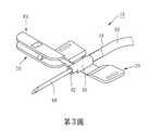
請先參閱第3圖,本發明之內廔管翼狀針10包含有一針座20、一針體60及一輸液管62。Please refer to FIG. 3 first. The inner
針座20由彈性材質以一體成型方式所製成(如塑膠射出成型製程),其包含有一導管30、二翼片40,以及一護蓋50,如第1及2圖所示:The
導管30呈中空狀且具有一前端32與一後端34。The
該二翼片40連接於導管30之左、右兩側面,其中一個翼片40之頂面具有一定位凸部42,另外一個翼片40之頂面具有一定位凹部44。此外,如第2圖所示,每一個翼片40之底面具有一止滑紋路46。The two
護蓋50連接於導管30之前端32的左側面,更明確地說,如第1、6及7圖所示,護蓋50具有一頂壁51、一底壁52、一端壁53、一側壁54及一連接壁55,端壁53連接於頂、底壁52之前端,側壁54連接頂壁51、底壁52及端壁53之左側邊,使得彼此之間圍繞出一朝右側開放之容針槽56,至於連接壁55連接在導管30之前端與側壁54之後端之間,使得護蓋50能相對導管30作彈性擺動。此外,如第1、2、6及7圖所示,在本實施例中,頂壁51及底壁52分別具有一開口57,該二開口57一前一後地相互錯開,護蓋50更具有二彈性肋部58,彈性肋部58之一端分別連接於開口57之周壁且自開口57朝容針槽56的方向斜伸而出。The
然而在此需要補充說明的是,開口57與彈性肋部58的數量可以根據實際需要進行調整,只要至少一個即可,更明確地說,開口57設於頂、底壁51、52的其中之一,彈性肋部58之一端一體地連接開口57之周壁且自開口57朝容針槽56的方向斜伸而出,如此亦能提供定位效果。However, it should be added here that the number of the opening 57 and the
針體60可以用一體成型的方式(如金屬埋入射出成型製程)固定於導管30之前端,也可以利用一黏著劑固定於導管30之前端,在此不加以限定。在針體60固定於導管30之後,針體60位於導管30之中心軸線A上,藉此,當護蓋50位於一開放位置P1(如第1及3圖所示)時,導管30之中心軸線A不會通過護蓋50之容針槽56,使得針體60完全顯露在外,當護蓋50位於一蓋合位置P2時(如第5及7圖所示),導管30之中心軸線A通過護蓋50之容針槽56,使針體60位於護蓋50之容針槽56內以避免外露。此外,當針體60位於護蓋50之容針槽56內時會同時被該二彈性肋部58所定位住,如第6及7圖所示,以確保護蓋50跟針體60不會輕易分開。The
輸液管62套設於導管30之後端34,用以輸送藥劑或血液。The
由上述可知,當要進行注射時,用手指將護蓋50從如第5圖所示之蓋合位置P2扳動至如第3圖所示之開放位置P1,使針體60完全顯露在外,接著再用兩根手指捏住該二翼片40,如第4圖所示,使該二翼片40之頂面相互抵靠,這時候的定位凸部42與定位凹部44會相互嵌卡,以避免該二翼片40相對移動而影響注射過程的穩定性,之後即可將針體60插入欲注射的部位,在完成針體60的插入之後釋放對該二翼片40的力量,並利用膠帶將該二翼片40黏貼於皮膚上,這時候可以進一步利用該二翼片40之止滑紋路46來穩定針體60的位置,如此即可透過輸液管62將藥劑輸送至人體內,或者是將血液從人體內抽出。It can be seen from the above that when the injection is to be performed, the
在完成前述注射動作之後把針體60抽出,再用手指將護蓋50從如第3圖所示之開放位置P1推動至如第5圖所示之蓋合位置P2,直到針體60位於容針槽56內且被該二彈性肋部58所定位住即完成收納(如第6及7圖所示)。After completing the aforementioned injection operation, withdraw the
綜上所陳,本發明所提供之針座20是用一體成型的方式所製成,與習用技術相比之下,不但有效地簡化結構及降低製造成本,在收納針體60時只需要一根手指即可完成護蓋50的操作,進而大幅減少手部與針體60接觸的機會,以達到增加操作便利性及提升收針安全性的目的。In summary, the
10‧‧‧內廔管翼狀針20‧‧‧針座30‧‧‧導管A‧‧‧中心軸線32‧‧‧前端34‧‧‧後端40‧‧‧翼片42‧‧‧定位凸部44‧‧‧定位凹部46‧‧‧止滑紋路50‧‧‧護蓋51‧‧‧頂壁52‧‧‧底壁53‧‧‧端壁54‧‧‧側壁55‧‧‧連接壁56‧‧‧容針槽57‧‧‧開口58‧‧‧彈性肋部60‧‧‧針體62‧‧‧輸液管P1‧‧‧開放位置P2‧‧‧蓋合位置10‧‧‧Inner
第1圖為本發明之針座的外觀立體圖。 第2圖為本發明之針座的底視圖。 第3圖為使用本發明之針座的內廔管翼狀針的外觀立體圖,主要顯示護蓋位於開放位置。 第4圖類同於第3圖,主要顯示二翼片之頂面相互抵靠。 第5圖類同於第3圖,主要護蓋位於蓋合位置。 第6圖為本發明之內廔管翼狀針的局部側視圖,主要顯示針體位於容針槽內且被彈性肋部給定位住。 第7圖為本發明之內廔管翼狀針的端面剖視圖,主要顯示針體位於容針槽內且被彈性肋部給定位住。Fig. 1 is a perspective view of the appearance of the needle holder of the present invention. Figure 2 is a bottom view of the needle holder of the present invention. FIG. 3 is a perspective view of the appearance of an inner tube wing needle using the needle holder of the present invention, mainly showing that the cover is in an open position. Figure 4 is the same as Figure 3, mainly showing that the top surfaces of the two wings abut against each other. Figure 5 is the same as Figure 3, with the main cover in the closed position. FIG. 6 is a partial side view of the inner tube wing needle of the present invention, mainly showing that the needle body is located in the needle receiving groove and is positioned by the elastic rib. FIG. 7 is a cross-sectional view of the end of the inner tube wing needle of the present invention, mainly showing that the needle body is located in the needle receiving groove and is positioned by the elastic rib.
20‧‧‧針座20‧‧‧Needle
30‧‧‧導管30‧‧‧Catheter
A‧‧‧中心軸線A‧‧‧Central axis
32‧‧‧前端32‧‧‧front
34‧‧‧後端34‧‧‧back
40‧‧‧翼片40‧‧‧wing
42‧‧‧定位凸部42‧‧‧Positioning
44‧‧‧定位凹部44‧‧‧Locating recess
50‧‧‧護蓋50‧‧‧Cover
51‧‧‧頂壁51‧‧‧Top wall
52‧‧‧底壁52‧‧‧Bottom wall
55‧‧‧連接壁55‧‧‧ connection wall
56‧‧‧容針槽56‧‧‧Acceptance
57‧‧‧開口57‧‧‧ opening
58‧‧‧彈性肋部58‧‧‧Elastic rib
Claims (16)
Translated fromChinesePriority Applications (3)
| Application Number | Priority Date | Filing Date | Title |
|---|---|---|---|
| TW107119193ATWI675677B (en) | 2018-06-04 | 2018-06-04 | Needle seat for inner tube wing needle and inner tube wing pin using same |
| CN201811097570.1ACN110548196B (en) | 2018-06-04 | 2018-09-17 | Needle holder for internal fistula wing needle and internal fistula wing needle using the same |
| US16/417,916US20190366054A1 (en) | 2018-06-04 | 2019-05-21 | Winged needle hub and internal fistula needle set using same |
Applications Claiming Priority (1)
| Application Number | Priority Date | Filing Date | Title |
|---|---|---|---|
| TW107119193ATWI675677B (en) | 2018-06-04 | 2018-06-04 | Needle seat for inner tube wing needle and inner tube wing pin using same |
Publications (2)
| Publication Number | Publication Date |
|---|---|
| TWI675677B TWI675677B (en) | 2019-11-01 |
| TW202003060Atrue TW202003060A (en) | 2020-01-16 |
Family
ID=68695331
Family Applications (1)
| Application Number | Title | Priority Date | Filing Date |
|---|---|---|---|
| TW107119193ATWI675677B (en) | 2018-06-04 | 2018-06-04 | Needle seat for inner tube wing needle and inner tube wing pin using same |
Country Status (3)
| Country | Link |
|---|---|
| US (1) | US20190366054A1 (en) |
| CN (1) | CN110548196B (en) |
| TW (1) | TWI675677B (en) |
Families Citing this family (1)
| Publication number | Priority date | Publication date | Assignee | Title |
|---|---|---|---|---|
| CN116392120B (en)* | 2023-04-25 | 2025-07-22 | 广州博联思医疗技术有限公司 | Blood taking needle |
Family Cites Families (12)
| Publication number | Priority date | Publication date | Assignee | Title |
|---|---|---|---|---|
| WO1990003196A1 (en)* | 1988-09-30 | 1990-04-05 | Utterberg David S | Guarded winged needle assembly |
| US5151089A (en)* | 1990-05-16 | 1992-09-29 | Kirk Iii William D | Retractable protective needle sheath |
| US6440104B1 (en)* | 1998-08-28 | 2002-08-27 | Becton, Dickinson And Company | Safety shield assembly |
| CA2422307A1 (en)* | 2002-03-20 | 2003-09-20 | Stefanie Livanos | Blood collection device |
| WO2008001590A1 (en)* | 2006-06-30 | 2008-01-03 | Nipro Corporation | Indwelling needle with wings |
| JP2010214096A (en)* | 2009-02-19 | 2010-09-30 | Jms Co Ltd | Medical needle device |
| SE536565C2 (en)* | 2012-06-29 | 2014-02-25 | Margaretha Mathiasson | Needle protection for needles |
| CN103191496B (en)* | 2013-04-10 | 2014-10-29 | 上海维朴芮国际贸易有限公司 | Butterfly-type needle assembly and butterfly-type needle protective sleeve |
| CN203841704U (en)* | 2014-03-26 | 2014-09-24 | 温州市贝普科技有限公司 | Safety blood taking needle |
| US20160151088A1 (en)* | 2014-12-02 | 2016-06-02 | Perfect Medical Industry Co., Ltd | Safety protective needle cover for butterfly needle assembly |
| CN106178187A (en)* | 2015-05-05 | 2016-12-07 | 郑万华 | Safe infusion needle device |
| TWM568710U (en)* | 2018-06-04 | 2018-10-21 | 洪志華 | Needle holder used in Fistuala needle and Fistula needle using the same |
- 2018
- 2018-06-04TWTW107119193Apatent/TWI675677B/enactive
- 2018-09-17CNCN201811097570.1Apatent/CN110548196B/enactiveActive
- 2019
- 2019-05-21USUS16/417,916patent/US20190366054A1/ennot_activeAbandoned
Also Published As
| Publication number | Publication date |
|---|---|
| CN110548196B (en) | 2022-03-22 |
| TWI675677B (en) | 2019-11-01 |
| CN110548196A (en) | 2019-12-10 |
| US20190366054A1 (en) | 2019-12-05 |
Similar Documents
| Publication | Publication Date | Title |
|---|---|---|
| JP7511704B2 (en) | CATHETER SYSTEM WITH GUIDEWIRE ADVANCEMENT ELEMENT - Patent application | |
| JP5073739B2 (en) | Venous catheter assembly with ergonomic needle grip | |
| JP4429630B2 (en) | Needle assembly and intravenous infusion device having the same | |
| US9585610B2 (en) | Medical needle | |
| TW201210649A (en) | Safety device for a pre-filled syringe and injection device | |
| US11213656B2 (en) | Medical device with anti-rotation push tab | |
| JP2003116991A (en) | Medical needle apparatus having shield with wing for preventing erroneous puncture | |
| JP2005530540A (en) | Improved safety butterfly needle | |
| TW202003060A (en) | Winged needle hub and internal fistula needle set using same | |
| CN111084653A (en) | Vascular puncture sheath | |
| CN209422650U (en) | Needle seat for internal fistula wing-shaped needle and internal fistula wing-shaped needle using same | |
| WO2018209498A1 (en) | Safe and open indwelling needle provided with forwards-extending needle bar | |
| JP5996656B2 (en) | Wing needle assembly | |
| JP2019198552A (en) | Indwelling needle device | |
| CN209137603U (en) | A kind of anti-venous indwelling needle | |
| JP6096229B2 (en) | How the needle assembly operates | |
| CN1970105A (en) | One-time safety intravenous indwelling needle | |
| CN221845764U (en) | Integrated central line catheter tube placing device | |
| WO2014033903A1 (en) | Butterfly needle | |
| TWM504606U (en) | Safety protective syringe | |
| CN1953777B (en) | One-time safety butterfly needle structure | |
| JP4500670B2 (en) | Protector and winged needle assembly | |
| CN212973756U (en) | Disposable scalp needle injury-proof needle head for venous transfusion | |
| JP6973134B2 (en) | Needle device | |
| CN1819851A (en) | Needle head structure of syringe |