TW202000975A - Substrate processing apparatus and shower head - Google Patents
Substrate processing apparatus and shower headDownload PDFInfo
- Publication number
- TW202000975A TW202000975ATW108118678ATW108118678ATW202000975ATW 202000975 ATW202000975 ATW 202000975ATW 108118678 ATW108118678 ATW 108118678ATW 108118678 ATW108118678 ATW 108118678ATW 202000975 ATW202000975 ATW 202000975A
- Authority
- TW
- Taiwan
- Prior art keywords
- cylindrical wall
- wall
- base member
- cylindrical
- gas
- Prior art date
Links
- 238000012545processingMethods0.000titleclaimsabstractdescription70
- 239000000758substrateSubstances0.000titleclaimsabstractdescription26
- 238000012546transferMethods0.000claimsabstractdescription13
- 238000009826distributionMethods0.000claimsdescription18
- 239000007921spraySubstances0.000claimsdescription13
- 230000001681protective effectEffects0.000claimsdescription10
- 239000004020conductorSubstances0.000claimsdescription6
- 239000007789gasSubstances0.000description124
- 235000012431wafersNutrition0.000description54
- 238000000034methodMethods0.000description25
- 238000009792diffusion processMethods0.000description19
- 238000004140cleaningMethods0.000description14
- 229910004298SiO 2Inorganic materials0.000description9
- 238000005516engineering processMethods0.000description9
- PXHVJJICTQNCMI-UHFFFAOYSA-NNickelChemical compound[Ni]PXHVJJICTQNCMI-UHFFFAOYSA-N0.000description8
- 230000015572biosynthetic processEffects0.000description6
- 238000000231atomic layer depositionMethods0.000description5
- 239000000463materialSubstances0.000description5
- 238000001179sorption measurementMethods0.000description5
- 229910052782aluminiumInorganic materials0.000description4
- XAGFODPZIPBFFR-UHFFFAOYSA-NaluminiumChemical compound[Al]XAGFODPZIPBFFR-UHFFFAOYSA-N0.000description4
- 230000003028elevating effectEffects0.000description4
- 239000011261inert gasSubstances0.000description4
- 229910052759nickelInorganic materials0.000description4
- 238000009825accumulationMethods0.000description3
- 230000006870functionEffects0.000description3
- 229910052751metalInorganic materials0.000description3
- 239000002184metalSubstances0.000description3
- 239000001301oxygenSubstances0.000description3
- 229910052760oxygenInorganic materials0.000description3
- 239000004065semiconductorSubstances0.000description3
- XKRFYHLGVUSROY-UHFFFAOYSA-NArgonChemical compound[Ar]XKRFYHLGVUSROY-UHFFFAOYSA-N0.000description2
- 239000006227byproductSubstances0.000description2
- 238000010586diagramMethods0.000description2
- 239000003989dielectric materialSubstances0.000description2
- 238000003780insertionMethods0.000description2
- 230000037431insertionEffects0.000description2
- 239000011810insulating materialSubstances0.000description2
- 238000009413insulationMethods0.000description2
- 239000012774insulation materialSubstances0.000description2
- 239000007769metal materialSubstances0.000description2
- 238000005192partitionMethods0.000description2
- 239000010453quartzSubstances0.000description2
- 239000002994raw materialSubstances0.000description2
- 239000012495reaction gasSubstances0.000description2
- VYPSYNLAJGMNEJ-UHFFFAOYSA-Nsilicon dioxideInorganic materialsO=[Si]=OVYPSYNLAJGMNEJ-UHFFFAOYSA-N0.000description2
- 238000005507sprayingMethods0.000description2
- 229910000990Ni alloyInorganic materials0.000description1
- RTAQQCXQSZGOHL-UHFFFAOYSA-NTitaniumChemical compound[Ti]RTAQQCXQSZGOHL-UHFFFAOYSA-N0.000description1
- 229910052786argonInorganic materials0.000description1
- QVGXLLKOCUKJST-UHFFFAOYSA-Natomic oxygenChemical compound[O]QVGXLLKOCUKJST-UHFFFAOYSA-N0.000description1
- 238000004891communicationMethods0.000description1
- 238000000151depositionMethods0.000description1
- 230000000694effectsEffects0.000description1
- 230000005611electricityEffects0.000description1
- 238000010438heat treatmentMethods0.000description1
- 238000004519manufacturing processMethods0.000description1
- OWKFQWAGPHVFRF-UHFFFAOYSA-Nn-(diethylaminosilyl)-n-ethylethanamineChemical compoundCCN(CC)[SiH2]N(CC)CCOWKFQWAGPHVFRF-UHFFFAOYSA-N0.000description1
- 230000003287optical effectEffects0.000description1
- 239000013307optical fiberSubstances0.000description1
- -1oxygen ionsChemical class0.000description1
- 239000002245particleSubstances0.000description1
- 230000000149penetrating effectEffects0.000description1
- 238000009832plasma treatmentMethods0.000description1
- 239000002243precursorSubstances0.000description1
- 230000001902propagating effectEffects0.000description1
- 239000010935stainless steelSubstances0.000description1
- 229910001220stainless steelInorganic materials0.000description1
- 239000010936titaniumSubstances0.000description1
- 229910052719titaniumInorganic materials0.000description1
Images


Classifications
- C—CHEMISTRY; METALLURGY
- C23—COATING METALLIC MATERIAL; COATING MATERIAL WITH METALLIC MATERIAL; CHEMICAL SURFACE TREATMENT; DIFFUSION TREATMENT OF METALLIC MATERIAL; COATING BY VACUUM EVAPORATION, BY SPUTTERING, BY ION IMPLANTATION OR BY CHEMICAL VAPOUR DEPOSITION, IN GENERAL; INHIBITING CORROSION OF METALLIC MATERIAL OR INCRUSTATION IN GENERAL
- C23C—COATING METALLIC MATERIAL; COATING MATERIAL WITH METALLIC MATERIAL; SURFACE TREATMENT OF METALLIC MATERIAL BY DIFFUSION INTO THE SURFACE, BY CHEMICAL CONVERSION OR SUBSTITUTION; COATING BY VACUUM EVAPORATION, BY SPUTTERING, BY ION IMPLANTATION OR BY CHEMICAL VAPOUR DEPOSITION, IN GENERAL
- C23C16/00—Chemical coating by decomposition of gaseous compounds, without leaving reaction products of surface material in the coating, i.e. chemical vapour deposition [CVD] processes
- C23C16/44—Chemical coating by decomposition of gaseous compounds, without leaving reaction products of surface material in the coating, i.e. chemical vapour deposition [CVD] processes characterised by the method of coating
- C23C16/455—Chemical coating by decomposition of gaseous compounds, without leaving reaction products of surface material in the coating, i.e. chemical vapour deposition [CVD] processes characterised by the method of coating characterised by the method used for introducing gases into reaction chamber or for modifying gas flows in reaction chamber
- C23C16/45563—Gas nozzles
- C23C16/45565—Shower nozzles
- C—CHEMISTRY; METALLURGY
- C23—COATING METALLIC MATERIAL; COATING MATERIAL WITH METALLIC MATERIAL; CHEMICAL SURFACE TREATMENT; DIFFUSION TREATMENT OF METALLIC MATERIAL; COATING BY VACUUM EVAPORATION, BY SPUTTERING, BY ION IMPLANTATION OR BY CHEMICAL VAPOUR DEPOSITION, IN GENERAL; INHIBITING CORROSION OF METALLIC MATERIAL OR INCRUSTATION IN GENERAL
- C23C—COATING METALLIC MATERIAL; COATING MATERIAL WITH METALLIC MATERIAL; SURFACE TREATMENT OF METALLIC MATERIAL BY DIFFUSION INTO THE SURFACE, BY CHEMICAL CONVERSION OR SUBSTITUTION; COATING BY VACUUM EVAPORATION, BY SPUTTERING, BY ION IMPLANTATION OR BY CHEMICAL VAPOUR DEPOSITION, IN GENERAL
- C23C16/00—Chemical coating by decomposition of gaseous compounds, without leaving reaction products of surface material in the coating, i.e. chemical vapour deposition [CVD] processes
- C23C16/22—Chemical coating by decomposition of gaseous compounds, without leaving reaction products of surface material in the coating, i.e. chemical vapour deposition [CVD] processes characterised by the deposition of inorganic material, other than metallic material
- C23C16/30—Deposition of compounds, mixtures or solid solutions, e.g. borides, carbides, nitrides
- C23C16/40—Oxides
- C23C16/401—Oxides containing silicon
- C23C16/402—Silicon dioxide
- C—CHEMISTRY; METALLURGY
- C23—COATING METALLIC MATERIAL; COATING MATERIAL WITH METALLIC MATERIAL; CHEMICAL SURFACE TREATMENT; DIFFUSION TREATMENT OF METALLIC MATERIAL; COATING BY VACUUM EVAPORATION, BY SPUTTERING, BY ION IMPLANTATION OR BY CHEMICAL VAPOUR DEPOSITION, IN GENERAL; INHIBITING CORROSION OF METALLIC MATERIAL OR INCRUSTATION IN GENERAL
- C23C—COATING METALLIC MATERIAL; COATING MATERIAL WITH METALLIC MATERIAL; SURFACE TREATMENT OF METALLIC MATERIAL BY DIFFUSION INTO THE SURFACE, BY CHEMICAL CONVERSION OR SUBSTITUTION; COATING BY VACUUM EVAPORATION, BY SPUTTERING, BY ION IMPLANTATION OR BY CHEMICAL VAPOUR DEPOSITION, IN GENERAL
- C23C16/00—Chemical coating by decomposition of gaseous compounds, without leaving reaction products of surface material in the coating, i.e. chemical vapour deposition [CVD] processes
- C23C16/44—Chemical coating by decomposition of gaseous compounds, without leaving reaction products of surface material in the coating, i.e. chemical vapour deposition [CVD] processes characterised by the method of coating
- C23C16/455—Chemical coating by decomposition of gaseous compounds, without leaving reaction products of surface material in the coating, i.e. chemical vapour deposition [CVD] processes characterised by the method of coating characterised by the method used for introducing gases into reaction chamber or for modifying gas flows in reaction chamber
- C23C16/45523—Pulsed gas flow or change of composition over time
- C23C16/45525—Atomic layer deposition [ALD]
- C23C16/45527—Atomic layer deposition [ALD] characterized by the ALD cycle, e.g. different flows or temperatures during half-reactions, unusual pulsing sequence, use of precursor mixtures or auxiliary reactants or activations
- C23C16/45536—Use of plasma, radiation or electromagnetic fields
- C—CHEMISTRY; METALLURGY
- C23—COATING METALLIC MATERIAL; COATING MATERIAL WITH METALLIC MATERIAL; CHEMICAL SURFACE TREATMENT; DIFFUSION TREATMENT OF METALLIC MATERIAL; COATING BY VACUUM EVAPORATION, BY SPUTTERING, BY ION IMPLANTATION OR BY CHEMICAL VAPOUR DEPOSITION, IN GENERAL; INHIBITING CORROSION OF METALLIC MATERIAL OR INCRUSTATION IN GENERAL
- C23C—COATING METALLIC MATERIAL; COATING MATERIAL WITH METALLIC MATERIAL; SURFACE TREATMENT OF METALLIC MATERIAL BY DIFFUSION INTO THE SURFACE, BY CHEMICAL CONVERSION OR SUBSTITUTION; COATING BY VACUUM EVAPORATION, BY SPUTTERING, BY ION IMPLANTATION OR BY CHEMICAL VAPOUR DEPOSITION, IN GENERAL
- C23C16/00—Chemical coating by decomposition of gaseous compounds, without leaving reaction products of surface material in the coating, i.e. chemical vapour deposition [CVD] processes
- C23C16/44—Chemical coating by decomposition of gaseous compounds, without leaving reaction products of surface material in the coating, i.e. chemical vapour deposition [CVD] processes characterised by the method of coating
- C23C16/455—Chemical coating by decomposition of gaseous compounds, without leaving reaction products of surface material in the coating, i.e. chemical vapour deposition [CVD] processes characterised by the method of coating characterised by the method used for introducing gases into reaction chamber or for modifying gas flows in reaction chamber
- C23C16/45563—Gas nozzles
- C23C16/4557—Heated nozzles
- C—CHEMISTRY; METALLURGY
- C23—COATING METALLIC MATERIAL; COATING MATERIAL WITH METALLIC MATERIAL; CHEMICAL SURFACE TREATMENT; DIFFUSION TREATMENT OF METALLIC MATERIAL; COATING BY VACUUM EVAPORATION, BY SPUTTERING, BY ION IMPLANTATION OR BY CHEMICAL VAPOUR DEPOSITION, IN GENERAL; INHIBITING CORROSION OF METALLIC MATERIAL OR INCRUSTATION IN GENERAL
- C23C—COATING METALLIC MATERIAL; COATING MATERIAL WITH METALLIC MATERIAL; SURFACE TREATMENT OF METALLIC MATERIAL BY DIFFUSION INTO THE SURFACE, BY CHEMICAL CONVERSION OR SUBSTITUTION; COATING BY VACUUM EVAPORATION, BY SPUTTERING, BY ION IMPLANTATION OR BY CHEMICAL VAPOUR DEPOSITION, IN GENERAL
- C23C16/00—Chemical coating by decomposition of gaseous compounds, without leaving reaction products of surface material in the coating, i.e. chemical vapour deposition [CVD] processes
- C23C16/44—Chemical coating by decomposition of gaseous compounds, without leaving reaction products of surface material in the coating, i.e. chemical vapour deposition [CVD] processes characterised by the method of coating
- C23C16/455—Chemical coating by decomposition of gaseous compounds, without leaving reaction products of surface material in the coating, i.e. chemical vapour deposition [CVD] processes characterised by the method of coating characterised by the method used for introducing gases into reaction chamber or for modifying gas flows in reaction chamber
- C23C16/45563—Gas nozzles
- C23C16/45574—Nozzles for more than one gas
- C—CHEMISTRY; METALLURGY
- C23—COATING METALLIC MATERIAL; COATING MATERIAL WITH METALLIC MATERIAL; CHEMICAL SURFACE TREATMENT; DIFFUSION TREATMENT OF METALLIC MATERIAL; COATING BY VACUUM EVAPORATION, BY SPUTTERING, BY ION IMPLANTATION OR BY CHEMICAL VAPOUR DEPOSITION, IN GENERAL; INHIBITING CORROSION OF METALLIC MATERIAL OR INCRUSTATION IN GENERAL
- C23C—COATING METALLIC MATERIAL; COATING MATERIAL WITH METALLIC MATERIAL; SURFACE TREATMENT OF METALLIC MATERIAL BY DIFFUSION INTO THE SURFACE, BY CHEMICAL CONVERSION OR SUBSTITUTION; COATING BY VACUUM EVAPORATION, BY SPUTTERING, BY ION IMPLANTATION OR BY CHEMICAL VAPOUR DEPOSITION, IN GENERAL
- C23C16/00—Chemical coating by decomposition of gaseous compounds, without leaving reaction products of surface material in the coating, i.e. chemical vapour deposition [CVD] processes
- C23C16/44—Chemical coating by decomposition of gaseous compounds, without leaving reaction products of surface material in the coating, i.e. chemical vapour deposition [CVD] processes characterised by the method of coating
- C23C16/50—Chemical coating by decomposition of gaseous compounds, without leaving reaction products of surface material in the coating, i.e. chemical vapour deposition [CVD] processes characterised by the method of coating using electric discharges
- C23C16/505—Chemical coating by decomposition of gaseous compounds, without leaving reaction products of surface material in the coating, i.e. chemical vapour deposition [CVD] processes characterised by the method of coating using electric discharges using radio frequency discharges
- C23C16/509—Chemical coating by decomposition of gaseous compounds, without leaving reaction products of surface material in the coating, i.e. chemical vapour deposition [CVD] processes characterised by the method of coating using electric discharges using radio frequency discharges using internal electrodes
- H—ELECTRICITY
- H01—ELECTRIC ELEMENTS
- H01L—SEMICONDUCTOR DEVICES NOT COVERED BY CLASS H10
- H01L21/00—Processes or apparatus adapted for the manufacture or treatment of semiconductor or solid state devices or of parts thereof
- H01L21/02—Manufacture or treatment of semiconductor devices or of parts thereof
- H01L21/04—Manufacture or treatment of semiconductor devices or of parts thereof the devices having potential barriers, e.g. a PN junction, depletion layer or carrier concentration layer
- H01L21/18—Manufacture or treatment of semiconductor devices or of parts thereof the devices having potential barriers, e.g. a PN junction, depletion layer or carrier concentration layer the devices having semiconductor bodies comprising elements of Group IV of the Periodic Table or AIIIBV compounds with or without impurities, e.g. doping materials
- H01L21/30—Treatment of semiconductor bodies using processes or apparatus not provided for in groups H01L21/20 - H01L21/26
- H01L21/302—Treatment of semiconductor bodies using processes or apparatus not provided for in groups H01L21/20 - H01L21/26 to change their surface-physical characteristics or shape, e.g. etching, polishing, cutting
- H01L21/306—Chemical or electrical treatment, e.g. electrolytic etching
- H01L21/3065—Plasma etching; Reactive-ion etching
- H—ELECTRICITY
- H01—ELECTRIC ELEMENTS
- H01L—SEMICONDUCTOR DEVICES NOT COVERED BY CLASS H10
- H01L21/00—Processes or apparatus adapted for the manufacture or treatment of semiconductor or solid state devices or of parts thereof
- H01L21/02—Manufacture or treatment of semiconductor devices or of parts thereof
- H01L21/04—Manufacture or treatment of semiconductor devices or of parts thereof the devices having potential barriers, e.g. a PN junction, depletion layer or carrier concentration layer
- H01L21/18—Manufacture or treatment of semiconductor devices or of parts thereof the devices having potential barriers, e.g. a PN junction, depletion layer or carrier concentration layer the devices having semiconductor bodies comprising elements of Group IV of the Periodic Table or AIIIBV compounds with or without impurities, e.g. doping materials
- H01L21/30—Treatment of semiconductor bodies using processes or apparatus not provided for in groups H01L21/20 - H01L21/26
- H01L21/31—Treatment of semiconductor bodies using processes or apparatus not provided for in groups H01L21/20 - H01L21/26 to form insulating layers thereon, e.g. for masking or by using photolithographic techniques; After treatment of these layers; Selection of materials for these layers
Landscapes
- Chemical & Material Sciences (AREA)
- Engineering & Computer Science (AREA)
- General Chemical & Material Sciences (AREA)
- Chemical Kinetics & Catalysis (AREA)
- Materials Engineering (AREA)
- Mechanical Engineering (AREA)
- Metallurgy (AREA)
- Organic Chemistry (AREA)
- Physics & Mathematics (AREA)
- Plasma & Fusion (AREA)
- Computer Hardware Design (AREA)
- Condensed Matter Physics & Semiconductors (AREA)
- General Physics & Mathematics (AREA)
- Manufacturing & Machinery (AREA)
- Microelectronics & Electronic Packaging (AREA)
- Power Engineering (AREA)
- Electromagnetism (AREA)
- Inorganic Chemistry (AREA)
- Chemical Vapour Deposition (AREA)
- Plasma Technology (AREA)
- Formation Of Insulating Films (AREA)
Abstract
Description
Translated fromChinese本發明之各種態樣及實施形態係關於一種基板處理裝置及噴頭。Various aspects and embodiments of the present invention relate to a substrate processing apparatus and a shower head.
於半導體元件之製造步驟中,對半導體晶圓等基板進行成膜處理等處理。作為成膜方法,例如有ALD(Atomic Layer Deposition,原子層沈積)法等。於藉由ALD法進行成膜之成膜裝置中,一面對成膜對象之基板進行加熱,一面反覆進行向反應室內供給前驅物、沖洗基板之循環,藉此,使原子層逐層地堆積於基板表面,而於基板上形成所需之膜。於此種成膜裝置中,供載置基板之載置台與對載置於載置台之基板供給處理氣體之氣體供給部在處理容器內相對向,處理氣體自氣體供給部呈噴淋狀被供給(例如,參照專利文獻1)。In the manufacturing process of the semiconductor element, a process such as a film forming process is performed on a substrate such as a semiconductor wafer. As a film forming method, for example, there is an ALD (Atomic Layer Deposition) method. In the film forming apparatus that performs film formation by the ALD method, while heating the substrate facing the film formation object, the cycle of supplying the precursor to the reaction chamber and rinsing the substrate is repeated, thereby depositing atomic layers layer by layer The required film is formed on the substrate surface. In such a film-forming apparatus, the mounting table for mounting the substrate and the gas supply portion for supplying the processing gas to the substrate mounted on the mounting surface are opposed in the processing container, and the processing gas is supplied from the gas supply portion in the form of a shower (For example, refer to Patent Document 1).
上述氣體供給部被稱為噴頭等,具有處理氣體之導入埠口、及形成於最下部之氣體供給孔。又,噴頭於導入埠口與氣體供給孔之間,具有用以使氣體於水平方向擴散之擴散空間。The gas supply part is called a shower head or the like, and has an inlet port for processing gas and a gas supply hole formed in the lowermost part. In addition, the nozzle has a diffusion space for diffusing the gas in the horizontal direction between the inlet port and the gas supply hole.
專利文獻1之噴頭中,擴散空間被分割成3個,相互鄰接之擴散空間藉由間隔壁隔開,分別對擴散空間設置有氣體供給孔。該噴頭藉由個別地調節供給至各擴散空間之處理氣體之供給量,而控制對於基板之處理氣體之供給量,從而能成膜為均一之厚度。In the shower head of
再者,於專利文獻1之噴頭中,中央之擴散空間形成為俯視圓板狀,最外側之擴散空間形成為俯視環狀,位於兩擴散空間之間的中間之擴散空間亦形成為俯視環狀。又,該噴頭中,於與俯視環狀之擴散空間在俯視下重疊之位置,形成有複數個俯視圓形之處理氣體之導入埠口。[先前技術文獻][專利文獻]Furthermore, in the shower head of
[專利文獻1]美國專利申請公開第2009/0218317號說明書[Patent Document 1] Specification of US Patent Application Publication No. 2009/0218317
[發明所欲解決之問題][Problems to be solved by the invention]
然,於設置於噴頭內之擴散空間中,上部之構件與下部之構件隔著擴散空間分離。上部之構件與下部之構件雖然經由在擴散空間內流動之處理氣體而存在一些熱之移動,但於擴散空間內流動之處理氣體之熱傳係數較劃分擴散空間之間隔壁之熱傳係數低。因此,即便控制擴散空間之上部之構件之溫度分佈,亦難以將擴散空間之下部之構件之溫度分佈設為所需之分佈。[解決問題之技術手段]However, in the diffusion space provided in the spray head, the upper member and the lower member are separated via the diffusion space. Although there is some thermal movement of the upper member and the lower member through the processing gas flowing in the diffusion space, the heat transfer coefficient of the processing gas flowing in the diffusion space is lower than that of the partition wall dividing the diffusion space. Therefore, even if the temperature distribution of the upper part of the diffusion space is controlled, it is difficult to set the temperature distribution of the lower part of the diffusion space to the desired distribution.[Technical means to solve the problem]
本發明之一態樣係一種基板處理裝置,其具備:腔室;載置台,其配置於腔室內,供載置被處理基板;及噴頭,其配置於與載置台相對向之位置,向腔室內供給氣體。噴頭具有第1基礎構件、第2基礎構件、噴淋板及複數個傳熱構件。第1基礎構件包含第1圓筒壁、第2圓筒壁及第1上部壁。第1圓筒壁具有圓筒狀之形狀。第2圓筒壁係與第1圓筒壁同軸之圓筒狀,且直徑大於第1圓筒壁。第1上部壁連接第1圓筒壁之下端與第2圓筒壁之上端。第2基礎構件包含第3圓筒壁、第4圓筒壁及第2上部壁。第3圓筒壁係與第1圓筒壁同軸之圓筒狀,且直徑小於第1圓筒壁,且配置於由第1圓筒壁包圍之空間內。第4圓筒壁係與第1圓筒壁同軸之圓筒狀,且直徑大於第3圓筒壁,且直徑小於第2圓筒壁,且配置於由第2圓筒壁包圍之空間內。第2上部壁配置於第1上部壁之下方,連接第3圓筒壁之下端與第4圓筒壁之上端。噴淋板具有複數個貫通孔,固定於第2圓筒壁之下端及第4圓筒壁之下端。各傳熱構件配置於第1上部壁與第2上部壁之間,且接觸第1上部壁之下表面與第2上部壁之上表面。[發明之效果]An aspect of the present invention is a substrate processing apparatus, which includes: a chamber; a mounting table, which is arranged in the chamber for mounting a substrate to be processed; and a shower head, which is arranged at a position opposite to the mounting table, toward the chamber Gas supply indoors. The shower head has a first foundation member, a second foundation member, a shower plate, and a plurality of heat transfer members. The first base member includes a first cylindrical wall, a second cylindrical wall, and a first upper wall. The first cylindrical wall has a cylindrical shape. The second cylindrical wall is a cylindrical shape coaxial with the first cylindrical wall and has a larger diameter than the first cylindrical wall. The first upper wall connects the lower end of the first cylindrical wall and the upper end of the second cylindrical wall. The second base member includes a third cylindrical wall, a fourth cylindrical wall, and a second upper wall. The third cylindrical wall is a cylindrical shape coaxial with the first cylindrical wall, has a smaller diameter than the first cylindrical wall, and is arranged in a space surrounded by the first cylindrical wall. The fourth cylindrical wall is a cylindrical shape coaxial with the first cylindrical wall, has a larger diameter than the third cylindrical wall, and a smaller diameter than the second cylindrical wall, and is arranged in a space surrounded by the second cylindrical wall. The second upper wall is disposed below the first upper wall, and connects the lower end of the third cylindrical wall and the upper end of the fourth cylindrical wall. The shower plate has a plurality of through holes and is fixed to the lower end of the second cylindrical wall and the lower end of the fourth cylindrical wall. Each heat transfer member is disposed between the first upper wall and the second upper wall, and contacts the lower surface of the first upper wall and the upper surface of the second upper wall.[Effect of invention]
根據本發明之各種態樣及實施形態,能夠精度良好地控制噴頭之溫度分佈。According to various aspects and embodiments of the present invention, the temperature distribution of the spray head can be accurately controlled.
以下,基於圖式對所揭示之基板處理裝置及噴頭之實施形態進行詳細說明。再者,並非藉由以下之實施形態限定所揭示之基板處理裝置及噴頭。Hereinafter, the disclosed embodiments of the substrate processing apparatus and the shower head will be described in detail based on the drawings. In addition, the substrate processing apparatus and the shower head disclosed are not limited by the following embodiments.
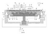
(第1實施形態)[電漿處理裝置1之構造]圖1係表示本發明之第1實施形態中之電漿處理裝置之一例的概略剖視圖。本實施形態中之電漿處理裝置1係CCP(Capacitively Coupled Plasma,電容耦合型電漿)處理裝置。電漿處理裝置1係基板處理裝置之一例。本實施形態中之電漿處理裝置1對作為被處理基板之一例之半導體晶圓W(以下,記載為晶圓W)藉由ALD法進行SiO2膜之成膜處理。具體而言,電漿處理裝置1藉由電漿增強ALD(PEALD,Plasma-enhanced Atomic Layer Deposition,電漿增強原子層沈積)於晶圓W形成SiO2膜。(First embodiment) [Structure of plasma processing apparatus 1] Fig. 1 is a schematic cross-sectional view showing an example of a plasma processing apparatus in a first embodiment of the present invention. The
電漿處理裝置1具備有底且上方開口之大致圓筒狀之腔室10。腔室10由例如鋁或鎳等金屬材料形成,藉由接地線12而接地。腔室10之內壁由襯墊(未圖示)覆蓋,該襯墊例如於表面形成有包含耐電漿性材料之熔射覆膜。於腔室10內設置有供載置晶圓W之載置台11。The
載置台11由例如鋁或鎳等金屬材料形成。載置台11之下表面由支持構件13支持,該支持構件13由導電性材料形成。支持構件13能夠藉由升降機構14而上下升降。升降機構14能夠藉由使支持構件13升降而使載置台11升降。The mounting table 11 is formed of a metal material such as aluminum or nickel. The lower surface of the mounting table 11 is supported by a supporting
載置台11之周圍由包含絕緣性或者介電性之材料之罩蓋構件130所覆蓋。載置台11經由支持構件13及升降機構14而電性接地於腔室10。載置台11作為與作為上部電極發揮功能之下述噴頭30成對之下部電極而發揮功能。再者,作為下部電極之構成,並不限定於本實施形態之內容,例如亦可為於載置台11內嵌埋有金屬篩網等導電性構件之絕緣性或者介電性之構件之構成。The periphery of the mounting table 11 is covered with a
於載置台11中內置有加熱器20,能夠將載置於載置台11之晶圓W加熱至特定溫度。又,於載置台11,在配置於其上表面部之絕緣性或者介電性之層之內部嵌埋有電極(未圖示)。藉由供給至該電極之直流電壓而於載置台11產生靜電力,藉由該靜電力將載置於載置台11之晶圓W吸附保持於載置台11之上表面。A
於腔室10之側壁形成有用以搬入及搬出晶圓W之開口15,開口15能夠藉由閘閥16而開閉。於載置台11之下方且腔室10之內側,設置有複數個支持銷(未圖示),於載置台11形成有供支持銷插通之插通孔(未圖示)。藉此,於使載置台11下降至晶圓W之搬入搬出位置時,能夠以貫通載置台11之插通孔之支持銷之上端部支承晶圓W,並與自腔室10之開口15侵入之搬送臂(未圖示)之間交接該晶圓W。An
於載置台11之上方且腔室10之內側,設置有噴頭30。噴頭30以相對於載置台11大致平行之方式配置。換言之,噴頭30係以與載置於載置台11之晶圓W相對向之方式配置。於腔室10內之空間中,將載置於載置台11上之晶圓W與噴頭30之間之空間特別記載為處理空間S。噴頭30由例如鋁或鎳等導電性之金屬形成。Above the mounting table 11 and inside the
噴頭30支持於由石英等介電體所形成之絕緣構件40。絕緣構件40藉由朝向絕緣構件40之外側突出之卡止部41支持於腔室10之上部。藉此,噴頭30經由絕緣構件40而支持於腔室10。The
噴頭30具有第1基礎構件32、第2基礎構件33、第3基礎構件34及噴淋板35。第1基礎構件32、第2基礎構件33及第3基礎構件34於俯視下為圓形狀,以中心成為軸X之方式配置。噴淋板35設置於第1基礎構件32、第2基礎構件33及第3基礎構件34之下端。於噴淋板35形成有複數個貫通孔。於第1基礎構件32與第2基礎構件33之間、第2基礎構件33與第3基礎構件34之間、及第3基礎構件34內,經由噴頭30之氣體導入部31,自氣體供給機構60供給處理氣體。向第1基礎構件32與第2基礎構件33之間、第2基礎構件33與第3基礎構件34之間、及第3基礎構件34內分別供給之處理氣體係自噴淋板35之各貫通孔呈噴淋狀供給至處理空間S內。The
氣體供給機構60具有供給原料氣體之氣體供給源62、供給反應氣體之氣體供給源63及供給惰性氣體之氣體供給源64。作為成膜SiO2膜時之原料氣體,例如使用BDEAS(Bis(diethylamino)silane,雙二乙基胺基矽烷)氣體。作為成膜SiO2膜時之反應氣體,例如使用O2(氧)氣體。作為惰性氣體,例如使用Ar(氬)氣體。又,氣體供給機構60具有包含閥或流量控制器等之供給調整部65。供給調整部65調整氣體種類、氣體之混合比、氣體之流量等處理氣體之供給條件。The
藉由供給調整部65調整供給條件後之氣體經由配管61a、配管61b及配管61c被供給至噴頭30之氣體導入部31。配管61a連接於第1基礎構件32與第2基礎構件33之間之空間,配管61b連接於第2基礎構件33與第3基礎構件34之間之空間,配管61c連接於第3基礎構件34內之空間。供給調整部65能夠獨立地調整經由配管61a、配管61b及配管61c供給至噴頭30之各氣體之供給條件。The gas whose supply conditions are adjusted by the
於噴頭30,經由整合器71而電性連接有高頻電源70。高頻電源70產生選自例如100 kHz~100 MHz之任意頻率之高頻電力。當於腔室10內生成電漿時,整合器71以高頻電源70之輸出阻抗與噴頭30之輸入阻抗於表觀上一致之方式發揮作用。連接整合器71與噴頭30之配線由導體之防護蓋覆蓋。高頻電源70係電漿生成部之一例。The
於絕緣構件40之上表面,以覆蓋噴頭30之方式設置有由金屬構成之防護蓋50。防護蓋50電性連接於腔室10,經由腔室10而接地。藉由防護蓋50抑制自噴頭30向腔室10之外部放射之不需要之高頻電力。A
於防護蓋50之上表面設置有溫度調整部51及溫度感測器53,溫度調整部51及溫度感測器53由隔熱材料52覆蓋。溫度感測器53係例如光纖溫度計等,測定噴頭30之溫度。溫度調整部51基於藉由溫度感測器53所測定之噴頭30之溫度,以噴頭30之溫度分佈成為特定之溫度分佈之方式對噴頭30進行加熱或者冷卻。於本實施形態中,溫度調整部51以噴頭30之溫度分佈成為特定之溫度分佈之方式對噴頭30進行加熱。藉此,能夠抑制因成膜處理而附著於噴頭30之下表面之反應副生成物、即所謂積存物,並且能夠提昇對晶圓W之製程之均一性。A
在絕緣構件40之外周與腔室10之側面之間形成有排氣空間83。又,於腔室10之側面連接有排氣管81。於排氣管81,經由壓力調整閥82而連接有包含真空泵等之排氣裝置80。藉由排氣裝置80,經由排氣空間83、排氣管81及壓力調整閥82將腔室10內之氣體排出。壓力調整閥82藉由調節排氣裝置80之排氣量而調整腔室10內之壓力。An
如上所述般構成之電漿處理裝置1由控制裝置100總括地控制其動作。控制裝置100具有處理器、記憶體及輸入輸出介面。於記憶體中儲存有藉由處理器執行之程式、及包含各處理之條件等之製程配方等。處理器藉由例如CPU(Central Processing Unit,中央處理單元)或DSP(Digital Signal Processor,數位信號處理器)等實現。處理器執行自記憶體讀出之程式,並基於記憶體內所記憶之製程配方等,經由輸入輸出介面控制電漿處理裝置1之各部。處理器例如控制升降機構14、加熱器20、溫度調整部51、供給調整部65、高頻電源70、整合器71、排氣裝置80及壓力調整閥82等。The operation of the
再者,記憶體內之程式等可自例如硬碟、軟碟、光碟、磁光碟、或者記憶卡等能夠藉由電腦讀取之記憶媒體讀出並儲存於記憶體內。又,記憶體內之程式等亦可經由通信線路自其他裝置獲取並儲存於記憶體內。Furthermore, the programs in the memory can be read out from the hard disk, floppy disk, optical disk, magneto-optical disk, or memory card, etc. which can be read by a computer and stored in the memory. In addition, the programs in the memory can also be obtained from other devices via the communication line and stored in the memory.
其次,對藉由電漿處理裝置1執行之向晶圓W成膜SiO2膜之成膜處理進行說明。於成膜處理時,首先,藉由升降機構14使載置台11下降至較開口15之位置更靠下,並打開閘閥16。然後,藉由搬送臂(未圖示)將晶圓W搬入至腔室10內,載置於載置台11上,並吸附保持於載置台11上。然後,關閉閘閥16,藉由升降機構14使載置台11上升至圖1所示之位置。再者,晶圓W向腔室10內之搬入係使用加載互鎖真空腔室等在真空狀態下進行。Next, the film forming process of forming the SiO2 film on the wafer W by the
繼而,藉由加熱器20將晶圓W控制為特定之溫度,藉由溫度調整部51將噴頭30控制為特定之溫度。晶圓W之溫度係以成為例如50~100℃之方式被調整,噴頭30之溫度係以成為例如100℃以上之方式被調整。Then, the
又,自氣體供給機構60將O2氣體及Ar氣體分別以特定之流量供給至噴頭30,並且藉由排氣裝置80排出腔室10內之氣體。供給至噴頭30之氣體於噴頭30內以軸X為中心向圓周方向擴散,自噴淋板35之貫通孔呈噴淋狀供給至腔室10內。供給調整部65將O2氣體之流量調整為大致100~10000 sccm,將Ar氣體之流量調整為大致100~5000 sccm。又,以腔室10內之壓力成為例如50 Pa~1300 Pa之方式,控制排氣裝置80之排氣量及壓力調整閥82之開度。In addition, O2 gas and Ar gas are respectively supplied to the
於晶圓W之溫度或腔室10內之壓力等穩定之階段,自氣體供給機構60除了供給上述O2氣體等以外,還將BDEAS氣體以特定之流量持續特定之期間供給至腔室10內。供給調整部65將BDEAS氣體之流量調整為大致5~200 sccm。藉此,BDEAS氣體之分子吸附於晶圓W(吸附步驟)。於本實施形態中,吸附步驟實施大致0.05~1秒。At a stage where the temperature of the wafer W or the pressure in the
於BDEAS氣體之吸附步驟之後,停止BDEAS氣體之供給,利用O2氣體及Ar氣體沖洗晶圓W之表面(第1沖洗步驟)。藉此,去除多餘吸附於晶圓W表面之BDEAS之分子。然後,藉由利用高頻電源70對噴頭30施加高頻電力,而使供給至腔室10內之O2氣體及Ar氣體電漿化。然後,藉由電漿而活化之氧離子或氧自由基被供給至晶圓W。藉此,吸附於晶圓W之BDEAS之分子被氧化而形成SiO2分子(反應步驟)。於本實施形態中,反應步驟實施大致0.2~0.5秒。After the BDEAS gas adsorption step, the supply of BDEAS gas is stopped, and the surface of the wafer W is rinsed with O2 gas and Ar gas (first rinse step). In this way, excess BDEAS molecules adsorbed on the surface of the wafer W are removed. Then, by applying high-frequency power to the
其後,停止高頻電力之施加,利用O2氣體及Ar氣體沖洗晶圓W之表面(第2沖洗步驟)。藉此,去除多餘生成於晶圓W表面之SiO2之分子。之後,藉由依序反覆實施吸附步驟、第1沖洗步驟、反應步驟、及第2沖洗步驟,而於晶圓W形成所需膜厚之SiO2膜。於晶圓W形成所需膜厚之SiO2膜後,自腔室10搬出晶圓W。然後,將新的晶圓W搬入至腔室10內,並重複上述一系列之處理。Thereafter, the application of high-frequency power is stopped, and the surface of the wafer W is rinsed with O2 gas and Ar gas (second rinse step). By this, excess SiO2 molecules generated on the surface of the wafer W are removed. After that, by sequentially performing the adsorption step, the first rinsing step, the reaction step, and the second rinsing step, an SiO2 film with a desired film thickness is formed on the wafer W. After the SiO2 film with a desired film thickness is formed on the wafer W, the wafer W is carried out from the
[噴頭30之構造]其次,對噴頭30之構造之詳情進行說明。圖2係表示第1實施形態中之噴頭30之一例之放大剖視圖。[Structure of Nozzle 30]Next, the details of the structure of the
例如,如圖2所示,噴頭30具有第1基礎構件32、第2基礎構件33、第3基礎構件34及噴淋板35。第2基礎構件33配置於由第1基礎構件32與噴淋板35包圍之空間內,第3基礎構件34配置於由第2基礎構件33與噴淋板35包圍之空間內。第1基礎構件32藉由螺釘36a而固定於噴淋板35,第2基礎構件33藉由螺釘36b而固定於噴淋板35,第3基礎構件34藉由螺釘36c而固定於噴淋板35。螺釘36a、螺釘36b及螺釘36c較佳為包含例如不鏽鋼等鎳合金或鈦等熱導率較高之材料。For example, as shown in FIG. 2, the
氣體導入部31包含氣體導入埠口31a~31c。氣體導入埠口31a將經由配管61a自供給調整部65供給之氣體供給至形成於第1基礎構件32與第2基礎構件33之間之空間內。供給至形成於第1基礎構件32與第2基礎構件33之間之空間內的氣體一面向以軸X為中心之圓之圓周方向擴散,一面向自軸X遠離之方向流動。然後,於形成於第1基礎構件32與第2基礎構件33之間之空間內擴散之氣體進而於形成於第1基礎構件32、第2基礎構件33及噴淋板35之間之空間35a內擴散。然後,於空間35a內擴散之氣體經由形成於噴淋板35之複數個貫通孔35d,呈噴淋狀被供給至處理空間S內。於空間35a內擴散之氣體被供給至載置於載置台11之晶圓W之區域中最外周之區域R3。The
氣體導入埠口31b將經由配管61b自供給調整部65供給之氣體供給至形成於第2基礎構件33與第3基礎構件34之間之空間內。供給至形成於第2基礎構件33與第3基礎構件34之間之空間內的氣體一面向以軸X為中心之圓之圓周方向擴散,一面向自軸X遠離之方向流動。然後,於形成於第2基礎構件33與第3基礎構件34之間之空間內擴散之氣體進而於形成於第2基礎構件33、第3基礎構件34及噴淋板35之間之空間35b內擴散。然後,於空間35b內擴散之氣體經由形成於噴淋板35之複數個貫通孔35d,呈噴淋狀被供給至處理空間S內。於空間35b內擴散之氣體被供給至載置於載置台11之晶圓W之區域中晶圓W之中央附近之區域R1與最外周之區域R3之間之區域R2。The
氣體導入埠口31c將經由配管61c自供給調整部65供給之氣體供給至形成於第3基礎構件34內之空間內。供給至第3基礎構件34之空間內之氣體沿軸X向噴淋板35之方向流動。然後,沿軸X向噴淋板35之方向流動之氣體進而於形成於第3基礎構件34與噴淋板35之間之空間35c內向以軸X為中心之圓之圓周方向擴散。然後,於空間35c內擴散之氣體經由形成於噴淋板35之複數個貫通孔35d,呈噴淋狀被供給至處理空間S內。於空間35c內擴散之氣體被供給至載置於載置台11之晶圓W之區域中晶圓W之中央附近之區域R1。The
此處,對噴頭30所具有之第1基礎構件32、第2基礎構件33及第3基礎構件34之形狀進一步詳細地進行說明。Here, the shapes of the
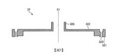
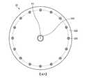
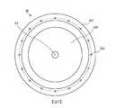
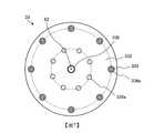
[第1基礎構件32之構造]圖3係表示第1基礎構件32之一例之剖視圖。圖4係表示第1基礎構件32之一例之俯視圖。圖5係表示第1基礎構件32之一例之仰視圖。[Structure of the first basic member 32]FIG. 3 is a cross-sectional view showing an example of the
例如,如圖3所示,第1基礎構件32具有圓筒壁320、圓筒壁321及上部壁322。圓筒壁320係第1圓筒壁之一例,圓筒壁321係第2圓筒壁之一例,上部壁322係第1上部壁之一例。For example, as shown in FIG. 3, the
圓筒壁320係中空之圓筒狀。將圓筒壁320之中心軸定義為軸X1。圓筒壁321係與圓筒壁320同軸之圓筒狀。又,於與軸X1交叉之剖面中,圓筒壁321之直徑大於圓筒壁320之直徑。上部壁322係以軸X1為中心之大致圓板狀,連接圓筒壁320之下端與圓筒壁321之上端。即,圓筒壁320自上部壁322之軸X1附近沿軸X1向第1方向延伸,圓筒壁321自上部壁322之外周部沿軸X1向與第1方向相反之方向延伸。The
於圓筒壁321形成有複數個螺紋孔323。例如,如圖4及圖5所示,複數個螺紋孔323以等間隔配置於以軸X1為中心之圓周上。第1基礎構件32藉由插入至各螺紋孔323之螺釘36a而固定於噴淋板35。藉此,自溫度調整部51傳遞至第1基礎構件32之熱經由固定第1基礎構件32與噴淋板35之螺釘36a、及與噴淋板35接觸之圓筒壁321之下端而傳遞至噴淋板35。A plurality of screw holes 323 are formed in the
[第2基礎構件33之構造]圖6係表示第2基礎構件33之一例之剖視圖。圖7係表示第2基礎構件33之一例之俯視圖。圖8係表示第2基礎構件33之一例之仰視圖。[Structure of the second base member 33]6 is a cross-sectional view showing an example of the
例如,如圖6所示,第2基礎構件33具有圓筒壁330、圓筒壁331及上部壁332。圓筒壁330係第3圓筒壁之一例,圓筒壁331係第4圓筒壁之一例,上部壁332係第2上部壁之一例。For example, as shown in FIG. 6, the
圓筒壁330係中空之圓筒狀。將圓筒壁330之中心軸定義為軸X2。與軸X2交叉之斷面中之圓筒壁330之直徑小於與軸X1交叉之斷面中之第1基礎構件32之圓筒壁320之直徑。於組裝為噴頭30之情形時,圓筒壁330以第2基礎構件33之軸X2與第1基礎構件32之軸X1一致之方式配置於由圓筒壁320包圍之空間內。即,於組裝為噴頭30之狀態下,第2基礎構件33之圓筒壁330之軸X2與第1基礎構件32之圓筒壁320之軸X1一致。The
圓筒壁331係與圓筒壁330同軸之圓筒狀。又,於與軸X2交叉之斷面中,圓筒壁331之直徑大於圓筒壁330之直徑。上部壁332係以軸X2為中心之大致圓板狀,連接圓筒壁330之下端與圓筒壁331之上端。即,圓筒壁330自上部壁332之軸X2附近沿軸X2向第2方向延伸,圓筒壁331自上部壁332之外周部沿軸X2向與第2方向相反之方向延伸。The
於上部壁332形成有複數個螺紋孔333。例如,如圖7及圖8所示,複數個螺紋孔333以等間隔配置於以軸X2為中心之圓周上。於各螺紋孔333中,在上部壁332之圓筒壁330側之面,以包圍螺紋孔333之方式設置有圓筒狀之肋部334a。又,於各螺紋孔333中,在上部壁332之圓筒壁331側之面,以包圍螺紋孔333之方式設置有圓筒狀之肋部334b。A plurality of screw holes 333 are formed in the
又,於上部壁332之圓筒壁330側之面設置有複數個突起部335a,於上部壁332之圓筒壁331側之面設置有複數個突起部335b。例如,如圖7及圖8所示,複數個突起部335a及335b以等間隔配置於以軸X2為中心之圓周上。In addition, a plurality of
於本實施形態中,自軸X2之方向觀察之情形時之各突起部335a及335b之形狀係大致圓形狀。藉此,能夠防止供給至第1基礎構件32與第2基礎構件33之間之空間的氣體之流動被突起部335a阻礙。同樣地,能夠防止供給至第2基礎構件33與第3基礎構件34之間之空間的氣體之流動被突起部335b阻礙。再者,自軸X2之方向觀察之情形時之突起部335a及335b之形狀只要為不阻礙氣體之流動之形狀,則亦可為橢圓形或板狀之形狀。但是,於採用橢圓形或板狀之形狀作為突起部335a及335b之形狀之情形時,突起部335a及335b較佳為以長度方向成為沿著自軸X2遠離之方向之朝向之方式配置。In this embodiment, the shapes of the
肋部334a及突起部335a於組裝成噴頭30之情形時,例如,如圖2所示,接觸第1基礎構件32之上部壁322之下表面。作為肋部334a及突起部335a之材料,可使用例如鋁或鎳等與噴頭30之材料相同之材料。藉此,第1基礎構件32之熱經由肋部334a及突起部335a效率良好地傳遞至第2基礎構件33。又,突起部335b於組裝成噴頭30之情形時,例如,如圖2所示,接觸第3基礎構件34。藉此,第2基礎構件33之熱經由突起部335b效率良好地傳遞至第3基礎構件34。肋部334a、突起部335a及突起部335b係傳熱構件之一例。When the
[第3基礎構件34之構造]圖9係表示第3基礎構件34之一例之剖視圖。圖10係表示第3基礎構件34之一例之俯視圖。圖11係表示第3基礎構件34之一例之仰視圖。[Structure of the third base member 34]9 is a cross-sectional view showing an example of the
例如,如圖9所示,第3基礎構件34具有圓筒壁340、圓筒壁341及上部壁342。圓筒壁340係中空之圓筒狀。將圓筒壁340之中心軸定義為軸X3。與軸X3交叉之斷面中之圓筒壁340之直徑小於與軸X2交叉之斷面中之第2基礎構件33之圓筒壁330之直徑。於組裝成噴頭30之情形時,第3基礎構件34以第3基礎構件34之軸X3與第2基礎構件33之軸X2一致之方式配置於由圓筒壁330包圍之空間內。即,於組裝成噴頭30之狀態下,第3基礎構件34之圓筒壁340之軸X3、第2基礎構件33之圓筒壁330之軸X2、及第1基礎構件32之圓筒壁320之軸X1一致。For example, as shown in FIG. 9, the
圓筒壁341係與圓筒壁340同軸之圓筒狀。又,於與軸X3交叉之斷面中,圓筒壁341之直徑大於圓筒壁340之直徑。上部壁342係以軸X3為中心之大致圓板狀,連接圓筒壁340之下端與圓筒壁341之上端。即,圓筒壁340自上部壁342之軸X3附近沿軸X3向第3方向延伸,圓筒壁341自上部壁342之外周部沿軸X3向與第3方向相反之方向延伸。The
於上部壁342形成有複數個螺紋孔343。例如,如圖10及圖11所示,複數個螺紋孔343以等間隔配置於以軸X3為中心之圓周上。於各螺紋孔343中,在上部壁342之圓筒壁340側之面,以包圍螺紋孔343之方式設置有圓筒狀之肋部344a。又,於各螺紋孔343中,在上部壁342之圓筒壁341側之面,以包圍螺紋孔343之方式設置有圓筒狀之肋部344b。A plurality of screw holes 343 are formed in the
於組裝成噴頭30之情形時,例如,如圖2所示,第2基礎構件33之突起部335b接觸第3基礎構件34之上部壁342之上表面。又,於組裝成噴頭30之情形時,例如,如圖2所示,第3基礎構件34之肋部344a接觸第2基礎構件33之上部壁332之下表面。藉此,第2基礎構件33之熱經由突起部335b及肋部344a效率良好地傳遞至第3基礎構件34。又,於組裝成噴頭30之情形時,例如,如圖2所示,肋部344b接觸噴淋板35。藉此,第3基礎構件34之熱經由肋部344b效率良好地傳遞至噴淋板35。In the case where the
此處,在第1基礎構件32與第2基礎構件33之間、及第2基礎構件33與第3基礎構件34之間形成有用以使自氣體供給機構60供給之氣體擴散之空間。因此,於在第2基礎構件33未設置肋部334a及突起部335a之情形時,第1基礎構件32之熱不會直接傳遞至第2基礎構件33。又,於在第2基礎構件33未設置肋部334b且在第3基礎構件34未設置肋部344a之情形時,第2基礎構件33之熱不會直接傳遞至第3基礎構件34。因此,即便藉由溫度調整部51控制第1基礎構件32之溫度分佈,亦難以將噴淋板35控制為所需之溫度分佈。Here, a space for diffusing the gas supplied from the
相對於此,本實施形態之噴頭30中,由於在第2基礎構件33設置有肋部334a及突起部335a,故第1基礎構件32之熱經由肋部334a及突起部335a直接傳遞至第2基礎構件33。又,於本實施形態之噴頭30中,由於在第2基礎構件33設置有突起部335b,故第2基礎構件33之熱直接傳遞至第3基礎構件34。進而,於本實施形態之噴頭30中,由於在第3基礎構件34設置有肋部344a,故第2基礎構件33之熱效率更加良好地傳遞至第3基礎構件34。藉此,能夠根據由溫度調整部51控制之第1基礎構件32之溫度分佈,將噴淋板35控制為所需之溫度分佈。In contrast, in the
再者,為了於面內均一地處理晶圓W,空間35a之寬度D1(參照圖2)較佳為較薄。但是,若過於薄,則對晶圓W之處理之均一性會降低。於本實施形態中,空間35a之寬度D1較佳為例如2~7 mm之範圍內之寬度。再者,空間35a之寬度D1更佳為例如2 mm。關於空間35b及空間35c之寬度亦同樣。Furthermore, in order to uniformly process the wafer W in the plane, the width D1 of the
又,為了提高對晶圓W之處理之均一性,第1基礎構件32之圓筒壁321與第2基礎構件33之圓筒壁331之間之空間之寬度D2(參照圖2)較佳為薄於特定之厚度。於本實施形態中,寬度D2較佳為例如6 mm以下之寬度。關於第2基礎構件33之圓筒壁331與第3基礎構件34之圓筒壁341之間之空間之寬度亦同樣。In order to improve the uniformity of the processing of the wafer W, the width D2 (see FIG. 2) of the space between the
為了提高對晶圓W之處理之均一性,第1基礎構件32之上部壁322與第2基礎構件33之上部壁332之間之空間之寬度D3(參照圖2)較佳為較薄。於本實施形態中,寬度D3較佳為例如1.5 mm~5 mm之範圍內之寬度。再者,寬度D3更佳為例如2 mm。關於第2基礎構件33之上部壁332與第3基礎構件34之上部壁342之間之空間之寬度亦同樣。In order to improve the uniformity of the processing of the wafer W, the width D3 (see FIG. 2) of the space between the
為了抑制作為噴頭30之裝置之大小,第2基礎構件33之上部壁332之厚度D4(參照圖2)較佳為較薄。關於第3基礎構件34之上部壁342之厚度亦同樣。為了提高對晶圓W之處理之均一性,第3基礎構件34之圓筒壁341之厚度D5(參照圖2)較佳為較薄。In order to suppress the size of the device as the
以上,對第1實施形態進行了說明。本實施形態之電漿處理裝置1具備:腔室10;載置台11,其配置於腔室10內,供載置晶圓W;及噴頭30,其配置於與載置台11相對向之位置,向腔室10內供給氣體。噴頭30具有第1基礎構件32、第2基礎構件33、噴淋板35及複數個突起部335a。第1基礎構件32包含圓筒壁320、圓筒壁321及上部壁322。圓筒壁320具有圓筒狀之形狀。圓筒壁321係與圓筒壁320同軸之圓筒狀,且直徑大於圓筒壁320。上部壁322連接圓筒壁320之下端與圓筒壁321之上端。第2基礎構件33包含圓筒壁330、圓筒壁331及上部壁332。圓筒壁330係與圓筒壁320同軸之圓筒狀,且直徑小於圓筒壁320,且配置於由圓筒壁320包圍之空間內。圓筒壁331係與圓筒壁320同軸之圓筒狀,且直徑大於圓筒壁330,且直徑小於圓筒壁321,且配置於由圓筒壁321包圍之空間內。上部壁332配置於上部壁322之下方,連接圓筒壁330之下端與圓筒壁331之上端。噴淋板35具有複數個貫通孔35d,配置於圓筒壁321之下端及圓筒壁331之下端。各突起部335a配置於上部壁322與上部壁332之間,且接觸上部壁322之下表面與上部壁332之上表面。藉此,能夠精度良好地控制噴頭30之溫度分佈。The first embodiment has been described above. The
又,於上述實施形態中,複數個突起部335a於以圓筒壁320之軸X為中心之圓之圓周方向上,以等間隔配置於上部壁322與上部壁332之間。藉此,能夠抑制上部壁322與上部壁332之間之氣體流動之偏倚。Furthermore, in the above-described embodiment, the plurality of
又,於上述實施形態中,在噴頭30之上部設置有控制噴頭30之溫度分佈之溫度調整部51。藉此,能夠精度良好地控制噴頭30之溫度分佈。In addition, in the above-described embodiment, a
又,於上述實施形態中,噴頭30包含導體。又,於上述實施形態中,電漿處理裝置1具備高頻電源70及防護蓋50。高頻電源70藉由對噴頭30供給高頻電力,而生成自噴頭30供給至腔室10內之氣體之電漿。防護蓋50包含導體,以覆蓋噴頭30之方式設置於噴頭30之上方,且接地。藉此,自噴頭30向腔室10之外部放射之不需要之高頻電力被遮斷。Furthermore, in the above embodiment, the
(第2實施形態)[電漿處理裝置1之構造]圖12係表示本發明之第2實施形態中之電漿處理裝置1之一例的概略剖視圖。再者,於圖12中,被標註與圖1相同之符號之構成由於除了以下要說明之方面以外與圖1中所說明之構成相同,故省略詳細說明。於本實施形態中之電漿處理裝置1中,供給至第3基礎構件34內之氣體、及供給至第2基礎構件33與第3基礎構件34之間之氣體被供給至晶圓W之區域。另一方面,於本實施形態中之電漿處理裝置1中,供給至第1基礎構件32與第2基礎構件33之間之氣體被供給至晶圓W之區域之外側區域。(Second embodiment)[Structure of Plasma Treatment Device 1]12 is a schematic cross-sectional view showing an example of the
[噴頭30之構造]圖13係表示第2實施形態中之噴頭30之一例之放大剖視圖。再者,於圖13中,被標註與圖2相同之符號之構成由於除了以下要說明之方面以外與圖2中所說明之構成相同,故省略詳細說明。於本實施形態中,例如,如圖13所示,供給至第1基礎構件32與第2基礎構件33之間之氣體經由貫通孔35d被供給至作為晶圓W之區域之外側區域的區域R3。又,於本實施形態中,噴頭30之側面未被絕緣構件40所覆蓋,第1基礎構件32及噴淋板35之側面相對於腔室10之排氣空間83露出。因此,自高頻電源70施加至噴頭30並於第1基礎構件32之表面傳播之高頻電力之一部分自第1基礎構件32之側面及噴淋板35之側面向排氣空間83放射。[Structure of Nozzle 30]FIG. 13 is an enlarged cross-sectional view showing an example of the
又,自噴淋板35之貫通孔35d供給至腔室10內之氣體通過排氣空間83自排氣管81排出。因此,自噴淋板35之貫通孔35d供給之氣體於通過排氣空間83內時藉由自噴頭30之側面放射至排氣空間83內之高頻電力而電漿化。然後,藉由電漿所包含之活性種,將於排氣空間83內附著於腔室10之表面之反應副生成物、即所謂積存物去除。In addition, the gas supplied from the through
於本實施形態中之電漿處理裝置1中,於進行成膜處理之情形時,在吸附步驟、第1沖洗步驟、反應步驟及第2沖洗步驟之各步驟中對區域R1及區域R2供給特定之氣體。另一方面,於本實施形態中之電漿處理裝置1中,於進行成膜處理之情形時,對區域R3,自區域R3上方之貫通孔35d供給例如Ar氣體等惰性氣體,或者不進行氣體之供給。又,於去除腔室10內之積存物之清潔步驟中,自區域R3上方之貫通孔35d向區域R3供給清潔用之氣體。作為清潔用之氣體,可使用例如ClF3氣體或NF3氣體等。In the
再者,於清潔步驟中,為了產生自區域R1及區域R2向區域R3之氣體流動,亦可對區域R1及區域R2供給例如Ar氣體等惰性氣體。藉此,能夠防止藉由清潔而自排氣空間83去除之微粒侵入至區域R1及區域R2。又,於清潔步驟中,為了保護載置台11,亦可於配置晶圓W之位置載置虛設晶圓。又,於清潔步驟中,由於目的係去除排氣空間83內之積存物,故只要於排氣空間83內生成電漿即可。因此,較佳為以於區域R1~R3中不產生電漿之方式調整氣體之流量、腔室10內之壓力及高頻電力之大小等。又,為了於區域R1~R3中不產生電漿,亦可使成為噴頭30之對向電極之載置台11下降。再者,藉由使載置台11自噴頭30遠離,亦可獲得腔室10之壁面與作為上部電極之噴頭30容易耦合之效果。In addition, in the cleaning step, in order to generate gas flow from the region R1 and the region R2 to the region R3, an inert gas such as Ar gas may be supplied to the region R1 and the region R2. Thereby, the particles removed from the
以上,對第2實施形態進行了說明。於本實施形態之電漿處理裝置1中,第1基礎構件32之圓筒壁321之側面相對於腔室10之內側壁露出。又,供給至第1基礎構件32與第2基礎構件33之間之氣體經由噴淋板35所具有之複數個貫通孔35d被噴出至載置於載置台11之晶圓W之區域之外側區域。藉此,能夠使用相同構成之電漿處理裝置1實行成膜處理與腔室10之側壁之清潔。The second embodiment has been described above. In the
(第3實施形態)[噴頭30之構造]圖14係表示第3實施形態中之噴頭30之一例之放大剖視圖。再者,於圖14中,被標註與圖2或者圖13相同之符號之構成由於除了以下要說明之方面以外與圖2或者圖13中所說明之構成相同,故省略詳細說明。又,關於電漿處理裝置1之整體構成,由於除了以下要說明之方面以外與使用圖12所說明之第2實施形態中之電漿處理裝置1相同,故省略說明。(Third Embodiment)[Structure of Nozzle 30]FIG. 14 is an enlarged cross-sectional view showing an example of the
於本實施形態中,例如,如圖14所示,於被供給第1基礎構件32與第2基礎構件33之間之氣體的區域R3處之噴淋板35之下表面設置有罩蓋構件37,該方面與第2實施形態不同。罩蓋構件37由例如石英等介電體形成。In this embodiment, for example, as shown in FIG. 14, a
於本實施形態中之電漿處理裝置1中,藉由在區域R3處之噴淋板35之下表面設置罩蓋構件37,能夠抑制自噴淋板35之下表面放射至區域R3之高頻電力。藉此,能夠抑制區域R3中之電漿之產生,於清潔步驟中,能夠抑制配置於區域R3之罩蓋構件130等構件受到之損壞。In the
再者,於本實施形態中之電漿處理裝置1中,於進行成膜處理之情形時,例如,如圖15所示,藉由升降機構14使載置台11上升至靠近噴頭30之位置。然後,以成為於處理空間S中容易產生電漿之條件之方式,調整氣體之流量、腔室10內之壓力及高頻電力之大小等。又,於本實施形態中之電漿處理裝置1中,於進行腔室10內之清潔之情形時,例如,如圖16所示,亦可藉由升降機構14使載置台11下降至自噴頭30離開之位置。然後,以成為於處理空間S中難以產生電漿且於排氣空間83中容易產生電漿之條件之方式,調整氣體之流量、腔室10內之壓力及高頻電力之大小等。再者,於進行腔室10內之清潔之情形時,亦可於載置台11上載置用以保護載置台11之虛設晶圓。In addition, in the
以上,對第3實施形態進行了說明。於本實施形態之電漿處理裝置1中,在圓筒壁331之下端與圓筒壁321之下端之間之噴淋板35之下表面設置有由介電體形成之罩蓋構件37。藉此,抑制放射至與圓筒壁331之下端和圓筒壁321之下端之間的區域對應之噴淋板35之下方之區域R3的高頻電力。藉此,於進行腔室10內之清潔時,能夠抑制對位於區域R3之構件造成之損壞。The third embodiment has been described above. In the
[其他]再者,本案所揭示之技術並不限定於上述實施形態,能夠於其主旨之範圍內進行各種變化。[other]In addition, the technology disclosed in this case is not limited to the above-mentioned embodiment, and various changes can be made within the scope of the gist thereof.
例如,於上述各實施形態中,作為基板處理裝置以電漿處理裝置1為例進行了說明,但揭示之技術並不限於此。例如,只要為使用氣體對晶圓W進行處理且進行將氣體供給至晶圓W之噴頭30之溫度分佈之控制的裝置,則亦能夠對不使用電漿之裝置應用揭示之技術。For example, in the above embodiments, the
又,於上述各實施形態中,作為電漿之產生方式以電容耦合型電漿(CCP)為例進行了說明,但揭示之技術並不限於此。例如,於使用氣體對晶圓W進行處理之裝置且進行將氣體供給至晶圓W之噴頭30之溫度分佈之控制的電漿處理裝置中,亦可應用揭示之技術。Furthermore, in each of the above-mentioned embodiments, the capacitive generation plasma (CCP) has been described as an example of the plasma generation method, but the disclosed technology is not limited to this. For example, the disclosed technique can also be applied to a plasma processing apparatus that uses a gas to process the wafer W and controls the temperature distribution of the
又,於上述各實施形態中,突起部335a及335b係設置於第2基礎構件33之上部壁332,但揭示之技術並不限於此。例如,突起部335a亦可設置於第1基礎構件32之上部壁322之下表面,突起部335b亦可設置於第3基礎構件34之上部壁342之上表面。In addition, in the above embodiments, the
又,於上述各實施形態中,突起部335a及335b係與上部壁332一體地形成於第2基礎構件33之上部壁332,但揭示之技術並不限於此。例如,突起部335a及335b亦可構成為與第2基礎構件33不同之構件,並安裝於第2基礎構件33。Furthermore, in the above embodiments, the
又,於上述第3實施形態中,於區域R3中自噴淋板35向下方供給氣體,但揭示之技術並不限於此。例如,亦可於與區域R3對應之噴淋板35之位置不設置貫通孔35d,而於第1基礎構件32之外周部之側面、或者噴淋板35之外周部之側面設置複數個貫通孔35d。或者,亦可於第1基礎構件32與噴淋板35之接合部之側面設置複數個貫通孔35d。藉此,供給至第1基礎構件32與噴淋板35之間之氣體朝向排氣空間83而非區域R3噴出。藉此,於清潔步驟中,易於形成在排氣空間83內容易生成電漿之條件,能夠效率良好地去除排氣空間83內之積存物。In addition, in the third embodiment described above, the gas is supplied downward from the
又,於上述各實施形態中,噴頭30具有3個基礎構件,但揭示之技術並不限於此,噴頭30亦可具有2個基礎構件,還可具有4個以上之基礎構件。Moreover, in each of the above-mentioned embodiments, the
又,於上述各實施形態中,各基礎構件之上部壁與噴淋板35以成為平行之方式配置,但揭示之技術並不限於此。例如,各基礎構件之上部壁亦可以隨著自軸X離開而高度變高或者高度變低之方式傾斜。Furthermore, in the above embodiments, the upper wall of each base member and the
再者,應認為本次所揭示之實施形態於所有方面為例示而非限制性者。實際上,上述實施形態能以各種形態實現。又,上述實施形態亦可於不脫離隨附之申請專利範圍及其主旨之情況下以各種形態進行省略、置換、變更。In addition, the embodiment disclosed this time should be considered as illustrative in all points and not restrictive. In fact, the above-mentioned embodiments can be realized in various forms. In addition, the above-mentioned embodiments may be omitted, replaced, or changed in various forms without departing from the scope of the attached patent application and its gist.
1‧‧‧電漿處理裝置10‧‧‧腔室11‧‧‧載置台12‧‧‧接地線13‧‧‧支持構件14‧‧‧升降機構15‧‧‧開口16‧‧‧閘閥20‧‧‧加熱器30‧‧‧噴頭31‧‧‧氣體導入部31a‧‧‧氣體導入埠口31b‧‧‧氣體導入埠口31c‧‧‧氣體導入埠口32‧‧‧第1基礎構件33‧‧‧第2基礎構件34‧‧‧第3基礎構件35‧‧‧噴淋板35a‧‧‧空間35b‧‧‧空間35c‧‧‧空間35d‧‧‧空間36a‧‧‧螺釘36b‧‧‧螺釘36c‧‧‧螺釘37‧‧‧罩蓋構件40‧‧‧絕緣構件41‧‧‧卡止部50‧‧‧防護蓋51‧‧‧溫度調整部52‧‧‧隔熱材料53‧‧‧溫度感測器60‧‧‧氣體供給機構61a‧‧‧配管61b‧‧‧配管61c‧‧‧配管62‧‧‧氣體供給源63‧‧‧氣體供給源64‧‧‧氣體供給源65‧‧‧供給調整部70‧‧‧高頻電源71‧‧‧整合器80‧‧‧排氣裝置81‧‧‧排氣管82‧‧‧壓力調整閥83‧‧‧排氣空間100‧‧‧控制裝置130‧‧‧罩蓋構件320‧‧‧圓筒壁321‧‧‧圓筒壁322‧‧‧上部壁323‧‧‧螺紋孔330‧‧‧圓筒壁331‧‧‧圓筒壁332‧‧‧上部壁333‧‧‧螺紋孔334a‧‧‧肋部334b‧‧‧肋部335a‧‧‧突起部335b‧‧‧突起部340‧‧‧圓筒壁341‧‧‧圓筒壁342‧‧‧上部壁343‧‧‧螺紋孔344a‧‧‧肋部344b‧‧‧肋部D1‧‧‧寬度D2‧‧‧寬度D3‧‧‧寬度D4‧‧‧厚度D5‧‧‧厚度R1‧‧‧區域R2‧‧‧區域R3‧‧‧區域S‧‧‧處理空間X‧‧‧軸X1‧‧‧軸X2‧‧‧軸X3‧‧‧軸W‧‧‧晶圓1‧‧‧Plasma processing device10‧‧‧ chamber11‧‧‧Stage12‧‧‧Ground wire13‧‧‧Support component14‧‧‧ Lifting mechanism15‧‧‧ opening16‧‧‧Gate valve20‧‧‧heater30‧‧‧Sprinkler31‧‧‧Gas Introduction Department31a‧‧‧Gas port31b‧‧‧Gas inlet port31c‧‧‧Gas inlet port32‧‧‧The first basic component33‧‧‧The second basic component34‧‧‧The third basic component35‧‧‧Spray board35a‧‧‧Space35b‧‧‧Space35c‧‧‧Space35d‧‧‧Space36a‧‧‧screw36b‧‧‧screw36c‧‧‧Screw37‧‧‧Cover member40‧‧‧Insulation41‧‧‧Locking part50‧‧‧Protective cover51‧‧‧Temperature adjustment department52‧‧‧Insulation material53‧‧‧Temperature sensor60‧‧‧Gas supply mechanism61a‧‧‧Piping61b‧‧‧Piping61c‧‧‧Piping62‧‧‧Gas supply source63‧‧‧ gas supply source64‧‧‧Gas supply source65‧‧‧ Supply Adjustment Department70‧‧‧High frequency power supply71‧‧‧integrator80‧‧‧Exhaust device81‧‧‧Exhaust pipe82‧‧‧Pressure adjustment valve83‧‧‧Exhaust space100‧‧‧Control device130‧‧‧Cover member320‧‧‧Cylinder wall321‧‧‧Cylinder wall322‧‧‧Upper wall323‧‧‧Threaded hole330‧‧‧Cylinder wall331‧‧‧Cylinder wall332‧‧‧Upper wall333‧‧‧Threaded hole334a‧‧‧rib334b‧‧‧rib335a‧‧‧Protrusion335b‧‧‧Projection340‧‧‧Cylinder wall341‧‧‧Cylinder wall342‧‧‧Upper wall343‧‧‧Threaded hole344a‧‧‧rib344b‧‧‧ribD1‧‧‧WidthD2‧‧‧WidthD3‧‧‧WidthD4‧‧‧thicknessD5‧‧‧thicknessR1‧‧‧RegionR2‧‧‧RegionR3‧‧‧RegionS‧‧‧ processing spaceX‧‧‧axisX1‧‧‧axisX2‧‧‧axisX3‧‧‧axisW‧‧‧ Wafer
圖1係表示本發明之第1實施形態中之電漿處理裝置之一例的概略剖視圖。圖2係表示第1實施形態中之噴頭之一例之放大剖視圖。圖3係表示第1基礎構件之一例之剖視圖。圖4係表示第1基礎構件之一例之俯視圖。圖5係表示第1基礎構件之一例之仰視圖。圖6係表示第2基礎構件之一例之剖視圖。圖7係表示第2基礎構件之一例之俯視圖。圖8係表示第2基礎構件之一例之仰視圖。圖9係表示第3基礎構件之一例之剖視圖。圖10係表示第3基礎構件之一例之俯視圖。圖11係表示第3基礎構件之一例之仰視圖。圖12係表示本發明之第2實施形態中之電漿處理裝置之一例的概略剖視圖。圖13係表示第2實施形態中之噴頭之一例之放大剖視圖。圖14係表示第3實施形態中之噴頭之一例之放大剖視圖。圖15係表示製程執行時之載置台之位置之一例的圖。圖16係表示清潔執行時之載置台之位置之一例的圖。FIG. 1 is a schematic cross-sectional view showing an example of a plasma processing apparatus in a first embodiment of the present invention.Fig. 2 is an enlarged cross-sectional view showing an example of a shower head in the first embodiment.3 is a cross-sectional view showing an example of the first base member.4 is a plan view showing an example of the first base member.FIG. 5 is a bottom view showing an example of the first base member.6 is a cross-sectional view showing an example of a second base member.7 is a plan view showing an example of a second base member.Fig. 8 is a bottom view showing an example of the second base member.9 is a cross-sectional view showing an example of a third base member.FIG. 10 is a plan view showing an example of a third base member.Fig. 11 is a bottom view showing an example of a third base member.12 is a schematic cross-sectional view showing an example of a plasma processing apparatus in a second embodiment of the present invention.13 is an enlarged cross-sectional view showing an example of a shower head in the second embodiment.14 is an enlarged cross-sectional view showing an example of a shower head in the third embodiment.15 is a diagram showing an example of the position of the mounting table when the process is executed.16 is a diagram showing an example of the position of the mounting table when cleaning is performed.
10‧‧‧腔室10‧‧‧ chamber
30‧‧‧噴頭30‧‧‧Sprinkler
31‧‧‧氣體導入部31‧‧‧Gas Introduction Department
31a‧‧‧氣體導入埠口31a‧‧‧Gas port
31b‧‧‧氣體導入埠口31b‧‧‧Gas inlet port
31c‧‧‧氣體導入埠口31c‧‧‧Gas inlet port
32‧‧‧第1基礎構件32‧‧‧The first basic component
33‧‧‧第2基礎構件33‧‧‧The second basic component
34‧‧‧第3基礎構件34‧‧‧The third basic component
35‧‧‧噴淋板35‧‧‧Spray board
35a‧‧‧空間35a‧‧‧Space
35b‧‧‧空間35b‧‧‧Space
35c‧‧‧空間35c‧‧‧Space
35d‧‧‧空間35d‧‧‧Space
36a‧‧‧螺釘36a‧‧‧screw
36b‧‧‧螺釘36b‧‧‧screw
36c‧‧‧螺釘36c‧‧‧Screw
40‧‧‧絕緣構件40‧‧‧Insulation
50‧‧‧防護蓋50‧‧‧Protective cover
51‧‧‧溫度調整部51‧‧‧Temperature adjustment department
52‧‧‧隔熱材料52‧‧‧Insulation material
81‧‧‧排氣管81‧‧‧Exhaust pipe
83‧‧‧排氣空間83‧‧‧Exhaust space
D1‧‧‧寬度D1‧‧‧Width
D2‧‧‧寬度D2‧‧‧Width
D3‧‧‧寬度D3‧‧‧Width
D4‧‧‧厚度D4‧‧‧thickness
D5‧‧‧厚度D5‧‧‧thickness
R1‧‧‧區域R1‧‧‧Region
R2‧‧‧區域R2‧‧‧Region
R3‧‧‧區域R3‧‧‧Region
S‧‧‧處理空間S‧‧‧ processing space
X‧‧‧軸X‧‧‧axis
Claims (7)
Translated fromChineseApplications Claiming Priority (2)
| Application Number | Priority Date | Filing Date | Title |
|---|---|---|---|
| JP2018-109760 | 2018-06-07 | ||
| JP2018109760 | 2018-06-07 |
Publications (1)
| Publication Number | Publication Date |
|---|---|
| TW202000975Atrue TW202000975A (en) | 2020-01-01 |
Family
ID=68770133
Family Applications (1)
| Application Number | Title | Priority Date | Filing Date |
|---|---|---|---|
| TW108118678ATW202000975A (en) | 2018-06-07 | 2019-05-30 | Substrate processing apparatus and shower head |
Country Status (6)
| Country | Link |
|---|---|
| US (1) | US20210079526A1 (en) |
| JP (1) | JPWO2019235282A1 (en) |
| KR (1) | KR20210018232A (en) |
| CN (1) | CN112166490A (en) |
| TW (1) | TW202000975A (en) |
| WO (1) | WO2019235282A1 (en) |
Families Citing this family (6)
| Publication number | Priority date | Publication date | Assignee | Title |
|---|---|---|---|---|
| WO2021257462A1 (en)* | 2020-06-15 | 2021-12-23 | Lam Research Corporation | Showerhead faceplates with angled gas distribution passages for semiconductor processing tools |
| KR102661859B1 (en)* | 2021-04-16 | 2024-04-30 | 주식회사 디스닉스 | Sputtering equipment including ion implantation shower head |
| JP7675814B2 (en)* | 2021-06-07 | 2025-05-13 | 京セラ株式会社 | Shower plate |
| KR102726133B1 (en)* | 2021-12-16 | 2024-11-05 | 주식회사 테스 | Showerhead assembly |
| US20240234192A1 (en)* | 2023-01-10 | 2024-07-11 | Taiwan Semiconductor Manufacturing Co., Ltd. | Method and Treatment System for Uniform Processing of Semiconductor Devices |
| FI131467B1 (en)* | 2023-04-11 | 2025-05-07 | Beneq Oy | Atomic layer deposition apparatus and method for coating a substrate |
Family Cites Families (5)
| Publication number | Priority date | Publication date | Assignee | Title |
|---|---|---|---|---|
| JP3310171B2 (en)* | 1996-07-17 | 2002-07-29 | 松下電器産業株式会社 | Plasma processing equipment |
| US7645341B2 (en)* | 2003-12-23 | 2010-01-12 | Lam Research Corporation | Showerhead electrode assembly for plasma processing apparatuses |
| US8066895B2 (en) | 2008-02-28 | 2011-11-29 | Applied Materials, Inc. | Method to control uniformity using tri-zone showerhead |
| US8679288B2 (en)* | 2008-06-09 | 2014-03-25 | Lam Research Corporation | Showerhead electrode assemblies for plasma processing apparatuses |
| JP4786731B2 (en)* | 2009-06-12 | 2011-10-05 | シャープ株式会社 | Plasma CVD equipment |
- 2019
- 2019-05-27JPJP2020523645Apatent/JPWO2019235282A1/ennot_activeCeased
- 2019-05-27WOPCT/JP2019/020892patent/WO2019235282A1/ennot_activeCeased
- 2019-05-27CNCN201980034967.2Apatent/CN112166490A/enactivePending
- 2019-05-27KRKR1020207033520Apatent/KR20210018232A/ennot_activeWithdrawn
- 2019-05-30TWTW108118678Apatent/TW202000975A/enunknown
- 2020
- 2020-11-20USUS16/953,363patent/US20210079526A1/ennot_activeAbandoned
Also Published As
| Publication number | Publication date |
|---|---|
| CN112166490A (en) | 2021-01-01 |
| WO2019235282A1 (en) | 2019-12-12 |
| KR20210018232A (en) | 2021-02-17 |
| US20210079526A1 (en) | 2021-03-18 |
| JPWO2019235282A1 (en) | 2021-06-17 |
Similar Documents
| Publication | Publication Date | Title |
|---|---|---|
| TW202000975A (en) | Substrate processing apparatus and shower head | |
| TWI747033B (en) | Semiconductor substrate supports with embedded rf shield | |
| US8636871B2 (en) | Plasma processing apparatus, plasma processing method and storage medium | |
| KR102831215B1 (en) | Planar substrate edge contact with open volume equalization pathways and side containment | |
| TW201923953A (en) | Single wafer processing environment with spatial separation | |
| KR101991574B1 (en) | Film forming apparatus and gas injection member user therefor | |
| TW201836008A (en) | Plasma processing apparatus | |
| TWI793701B (en) | Components such as edge rings including chemical vapor deposition (cvd) diamond coating with high purity sp3 bonds for plasma processing systems | |
| TW200921783A (en) | Substrate processing equipment, and showerhead | |
| TWI750269B (en) | Processing method and processing apparatus | |
| TW201544637A (en) | Symmetric chamber body design architecture to address variable process volume with improved flow uniformity/gas conductance | |
| JP6735549B2 (en) | Substrate processing apparatus, substrate processing method and ring-shaped member | |
| CN111326443A (en) | Equipment for manufacturing semiconductor devices | |
| TW202033819A (en) | Methods of operating a spatial deposition tool | |
| JP7440488B2 (en) | Prevention of vapor deposition on pedestals during semiconductor substrate processing | |
| JP6932070B2 (en) | Focus ring and semiconductor manufacturing equipment | |
| KR20070117797A (en) | Substrate treatment apparatus for uniform plasma discharge and method for controlling plasma discharge intensity using the same | |
| JP7725385B2 (en) | Plasma processing apparatus and plasma processing method | |
| US20250179638A1 (en) | Showerhead assembly and substrate processing systems for improving deposition thickness uniformity | |
| TW202342806A (en) | Showerhead assembly with heated showerhead | |
| TWI855024B (en) | Pedestals for modulating film properties in atomic layer deposition (ald) substrate processing chambers and system having the same | |
| TW201324577A (en) | Plasma processing device and edge ring applicable to the plasma processing device | |
| US12068152B2 (en) | Semiconductor substrate bevel cleaning | |
| TW202503106A (en) | Forming method for carbon- containing film |