RU2807314C1 - Installation for drying radioactive ion exchange resins - Google Patents
Installation for drying radioactive ion exchange resinsDownload PDFInfo
- Publication number
- RU2807314C1 RU2807314C1RU2023106212ARU2023106212ARU2807314C1RU 2807314 C1RU2807314 C1RU 2807314C1RU 2023106212 ARU2023106212 ARU 2023106212ARU 2023106212 ARU2023106212 ARU 2023106212ARU 2807314 C1RU2807314 C1RU 2807314C1
- Authority
- RU
- Russia
- Prior art keywords
- thermoreactor
- refrigerant
- cylindrical container
- water vapor
- exchange resins
- Prior art date
Links
- 230000002285radioactive effectEffects0.000titleclaimsabstractdescription29
- 239000003456ion exchange resinSubstances0.000titleclaimsabstractdescription27
- 229920003303ion-exchange polymerPolymers0.000titleclaimsabstractdescription27
- 238000001035dryingMethods0.000titleclaimsabstractdescription19
- 238000009434installationMethods0.000titleclaimsabstractdescription9
- 239000003507refrigerantSubstances0.000claimsabstractdescription47
- XLYOFNOQVPJJNP-UHFFFAOYSA-NwaterChemical compoundOXLYOFNOQVPJJNP-UHFFFAOYSA-N0.000claimsabstractdescription24
- 239000007788liquidSubstances0.000claimsdescription11
- 238000010438heat treatmentMethods0.000claimsdescription7
- 239000002826coolantSubstances0.000claimsdescription5
- 239000010857liquid radioactive wasteSubstances0.000abstractdescription6
- 238000005265energy consumptionMethods0.000abstractdescription4
- 239000000443aerosolSubstances0.000abstractdescription3
- 230000007774longtermEffects0.000abstractdescription2
- 230000000694effectsEffects0.000abstract1
- 239000000126substanceSubstances0.000abstract1
- 238000010586diagramMethods0.000description3
- 239000007789gasSubstances0.000description2
- 239000011347resinSubstances0.000description2
- 229920005989resinPolymers0.000description2
- 238000009834vaporizationMethods0.000description2
- 230000008016vaporizationEffects0.000description2
- 230000015572biosynthetic processEffects0.000description1
- 238000009835boilingMethods0.000description1
- 238000004140cleaningMethods0.000description1
- 238000010835comparative analysisMethods0.000description1
- 230000007423decreaseEffects0.000description1
- 238000005516engineering processMethods0.000description1
- 239000007792gaseous phaseSubstances0.000description1
- 230000008520organizationEffects0.000description1
- 238000009423ventilationMethods0.000description1
Images

Abstract
Description
Translated fromRussianЗаявляемое изобретение относится к устройствам обращения с жидкими радиоактивными отходами, в частности, с радиоактивными ионообменными смолами с получением продукта, пригодного для долговременного хранения.The claimed invention relates to devices for handling liquid radioactive waste, in particular, with radioactive ion exchange resins to produce a product suitable for long-term storage.
Известна установка для сушки радиоактивных ионообменных смол (Патент на изобретение 2735858 РФ МПК G21F 9/04 (2006.01). Установка для сушки радиоактивных ионообменных смол [Текст] / Мотыженкова Е.А., Пьянкова Е.Н., Соснина Ю.Н.; заявитель и патентообладатель Акционерное общество "Научно-исследовательское проектно-технологическое бюро "Онега" (АО "НИПТБ "Онега") - №2020118143; заявл. 02.06.2020; опубл. 09.11.2020, Бюл. №31), включающая в себя термореактор, включающий в себя цилиндрическую емкость и герметично закрывающуюся крышку, нагреватель, расположенный на наружной поверхности термореактора, конденсатор паров воды, соединенный магистралью с термореактором, конденсатоприемник, соединенный магистралью с конденсатором паров воды, вакуумный насос, вход которого соединен с конденсатоприемником, а выход - с магистралью для отвода воздуха, термореактор включает в себя мешалку, установленную на герметично закрывающейся крышке внутри термореактора и снабженную побудителем вращения, цилиндрическая емкость термореактора выполнена съемной, а нагреватель выполнен с возможностью разделения на две части и включает в себя нагревательный контур, заполненный хладагентом, и включает в себя теплообменник, соединенный с источником тепла, компрессор, конденсатор, редукционный клапан и инфракрасные нагреватели, причем конденсатор выполнен таким образом, что в собранном положении нагревателя он охватывает цилиндрическую емкость термореактора.A known installation for drying radioactive ion exchange resins (Patent for invention 2735858 RF IPC G21F 9/04 (2006.01). Installation for drying radioactive ion exchange resins [Text] / Motyzhenkova E.A., Pyankova E.N., Sosnina Yu.N.; applicant and patent holder Joint Stock Company Scientific Research Design and Technology Bureau Onega (JSC NIPTB Onega) - No. 2020118143; application 06/02/2020; published 11/09/2020, Bulletin No. 31), including a thermoreactor , which includes a cylindrical container and a hermetically sealed lid, a heater located on the outer surface of the thermoreactor, a water vapor condenser connected by a line to the thermoreactor, a condensate receiver connected by a line to the water vapor condenser, a vacuum pump, the input of which is connected to the condensate receiver, and the output to line for air removal, the thermoreactor includes a stirrer mounted on a hermetically sealed lid inside the thermoreactor and equipped with a rotation stimulator, the cylindrical container of the thermoreactor is removable, and the heater is designed to be divided into two parts and includes a heating circuit filled with refrigerant and includes it includes a heat exchanger connected to a heat source, a compressor, a condenser, a pressure reducing valve and infrared heaters, wherein the condenser is designed in such a way that in the assembled position of the heater it covers the cylindrical container of the thermoreactor.
Эта конструкция наиболее близка к заявляемому техническому решению, поэтому принята в качестве прототипа.This design is closest to the claimed technical solution, therefore it was adopted as a prototype.
Недостатком прототипа является высокое энергопотребление при выполнении сушки радиоактивных ионообменных смол.The disadvantage of the prototype is the high energy consumption when drying radioactive ion exchange resins.
Суть заявляемого технического решения заключается в том, что в известной установке для сушки радиоактивных ионообменных смол, включающей в себя термореактор, включающий в себя цилиндрическую емкость и герметично закрывающуюся крышку, нагреватель, расположенный на наружной поверхности термореактора, конденсатор паров воды, соединенный магистралью с термореактором, конденсатоприемник, соединенный магистралью с конденсатором паров воды, вакуумный насос, вход которого соединен с конденсатоприемником, а выход - с магистралью для отвода воздуха, термореактор включает в себя также мешалку, установленную на герметично закрывающейся крышке внутри термореактора и снабженную побудителем вращения, цилиндрическая емкость термореактора выполнена съемной, а нагреватель выполнен с возможностью разделения на две части и включает в себя нагревательный контур, заполненный хладагентом, и включает в себя теплообменник, соединенный с источником тепла, компрессор, конденсатор, редукционный клапан и инфракрасные нагреватели, причем конденсатор выполнен таким образом, что в собранном положении нагревателя он охватывает цилиндрическую емкость термореактора, к магистрали между термореактором и конденсатором паров воды добавлен паровой эжектор, к нагревательному контуру, заполненному хладагентом, добавлена дополнительная отключаемая ветка, также заполненная хладагентом, и включающая в себя насос подачи хладагента и также соединенная с конденсатором паров воды таким образом, что в подключенном положении жидкий хладагент, находящийся в указанной ветке, является вторичным теплоносителем конденсатора паров воды.The essence of the proposed technical solution is that in a known installation for drying radioactive ion exchange resins, which includes a thermoreactor, including a cylindrical container and a hermetically sealed lid, a heater located on the outer surface of the thermoreactor, a water vapor condenser connected by a line to the thermoreactor, a condensate receiver connected by a line to a water vapor condenser, a vacuum pump, the inlet of which is connected to the condensate receiver, and the output is connected to a line for air removal; the thermoreactor also includes a stirrer mounted on a hermetically sealed lid inside the thermoreactor and equipped with a rotation stimulator; the cylindrical container of the thermoreactor is made removable, and the heater is designed to be divided into two parts and includes a heating circuit filled with refrigerant, and includes a heat exchanger connected to a heat source, a compressor, a condenser, a pressure reducing valve and infrared heaters, wherein the condenser is designed in such a way that In the assembled position of the heater, it covers the cylindrical container of the thermoreactor, a steam ejector is added to the line between the thermoreactor and the water vapor condenser, an additional switchable branch is added to the heating circuit filled with refrigerant, also filled with refrigerant, and including a refrigerant supply pump and also connected to the vapor condenser water in such a way that in the connected position, the liquid refrigerant located in the specified branch is the secondary coolant of the water vapor condenser.
Таким образом, заявляемое техническое решение отличается от прототипа тем, что к магистрали между термореактором и конденсатором паров воды добавлен паровой эжектор, к нагревательному контуру, заполненному хладагентом, добавлена дополнительная отключаемая ветка, также заполненная хладагентом, и включающая в себя насос подачи хладагента и также соединенная с конденсатором паров воды таким образом, что в подключенном положении жидкий хладагент, находящийся в указанной ветке, является вторичным теплоносителем конденсатора паров воды.Thus, the claimed technical solution differs from the prototype in that a steam ejector is added to the line between the thermoreactor and the water vapor condenser, an additional switchable branch is added to the heating circuit filled with refrigerant, also filled with refrigerant, and including a refrigerant supply pump and also connected with a water vapor condenser in such a way that, in the connected position, the liquid refrigerant located in the specified branch is the secondary coolant of the water vapor condenser.
Сравнительный анализ данного технического решения с другими показал, что совокупность признаков заявляемого технического решения позволит сократить энергопотребление при выполнении сушки радиоактивных ионообменных смол.A comparative analysis of this technical solution with others showed that the combination of features of the proposed technical solution will reduce energy consumption when drying radioactive ion exchange resins.
Применение парового эжектора позволит собирать пар, выделяемый при сушке радиоактивных ионообменных смол.The use of a steam ejector will allow collecting steam released during the drying of radioactive ion exchange resins.
Дополнительная отключаемая ветка, также заполненная хладагентом, и также соединенная с конденсатором паров воды таким образом, что в подключенном положении жидкий хладагент, находящийся в указанной ветке, является вторичным теплоносителем конденсатора паров воды производить нагрев хладагента за счет тепловой энергии пара, выделяемого при сушке радиоактивных ионообменных смол.An additional disconnected branch, also filled with refrigerant, and also connected to the water vapor condenser in such a way that in the connected position, the liquid refrigerant located in the specified branch is the secondary coolant of the water vapor condenser to heat the refrigerant due to the thermal energy of the steam released during the drying of radioactive ion exchangers resin
Насос подачи хладагента позволит прокачивать хладагент через дополнительную отключаемую ветку.The refrigerant supply pump will allow you to pump refrigerant through an additional switchable branch.
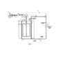
На фиг. 1 изображена схема установки для сушки радиоактивных ионообменных смол при выполнении циклов циркуляции с дополнительной отключаемой веткой в отключенном положении, с подачей низкопотенциального тепла.In fig. Figure 1 shows a diagram of an installation for drying radioactive ion-exchange resins when performing circulation cycles with an additional switchable branch in the off position, with the supply of low-grade heat.
На фиг. 2 изображена схема установки для сушки радиоактивных ионообменных смол при выполнении циклов циркуляции с дополнительной отключаемой веткой в подключенном положении, без подачи низкопотенциального тепла.In fig. Figure 2 shows a diagram of an installation for drying radioactive ion exchange resins when performing circulation cycles with an additional switchable branch in the connected position, without supplying low-grade heat.
Устройство включает в себя съемную цилиндрическую емкость 1, установленную на донном основании 2, и нагреватель 3. В герметично закрывающейся крышке цилиндрической емкости 1 размещена мешалка 4, которая приводится в движение побудителем вращения 5. На герметично закрывающейся крышке установлен вакуумный насос 6.The device includes a removable
На каждой части нагревателя 3 с внутренней стороны проложен конденсатор 7, выполненный таким образом, что в собранном положении нагревателя он плотно охватывает цилиндрическую емкость 1, входящий в состав контура циркуляции хладагента.On each part of the heater 3, on the inside there is a
К герметично закрывающейся крышке подведена магистраль вывода конденсата, на которой установлен паровой эжектор 8. Паровой эжектор 8 соединен с конденсатором паров воды 9. Конденсатор паров воды 9 соединен с конденсатоотводчиком 10, который соединен с насосом вывода конденсата 11 и фильтром для очистки от радиоактивных аэрозолей 12. Насос вывода конденсата 11 соединен со специальной емкостью для сбора жидких радиоактивных отходов 13.A condensate outlet line is connected to the hermetically sealed lid, on which a steam ejector 8 is installed. The steam ejector 8 is connected to a water vapor condenser 9. The water vapor condenser 9 is connected to a
Контур циркуляции хладагента состоит из теплообменника 14, соединенного с источником тепла (на схеме не показан), компрессора 15, конденсатора 7, выполненного таким образом, что в собранном положении нагревателя плотно охватывает цилиндрическую емкость термореактора, редукционного клапана 16, насоса подачи хладагента 17.The refrigerant circulation circuit consists of a
Заявляемая установка работает следующим образом. Для выполнения сушки радиоактивные ионообменные смолы загружаются в съемную цилиндрическую емкость 1, в качестве которой может быть использована, например, стандартная бочка типа Б31А-216,5. Съемную цилиндрическую емкость 1 устанавливают на донное основание 2 так, чтобы обе части нагревателя 3 охватывали боковые стенки съемной цилиндрической емкости, затем части нагревателя 3 фиксируют между собой, например замком. Со съемной цилиндрической емкости 1 снимают стационарную крышку, если она есть, и закрывают герметично закрывающейся крышкой.The inventive installation works as follows. To perform drying, radioactive ion exchange resins are loaded into a removable
В начале процесса сушки радиоактивных ионообменных смол цикл циркуляции хладагента проходит в контуре, показанном на фиг.1, при этом дополнительная отключаемая ветка находится в отключенном положении. В теплообменник 14 поступает низкопотенциальное тепло, например, удаляемый из помещения вентиляционный воздух, подводимый при помощи компрессора. Теплообменник 14 заполнен хладагентом, например марки R114, который находится в жидком состоянии и имеет низкое давление.At the beginning of the drying process of radioactive ion exchange resins, the refrigerant circulation cycle takes place in the circuit shown in Fig. 1, with an additional switchable branch in the off position. The
Хладагент, проходя через теплообменник 14, нагревается до температуры кипения, которая, например, для хладагента R114 составляет плюс 3,6°С, переходит из жидкого состояния в газообразное, далее нагревается до температуры теплоносителя, в данном случае до плюс 6°С.The refrigerant, passing through the
Далее хладагент в газообразном состоянии поступает в компрессор 15, где происходит сжатие хладагента, за счет резкого увеличения давления происходит повышение температуры хладагента до температуры, требуемой для начала парообразования радиоактивных ионообменных смол (плюс 50-60°С).Next, the refrigerant in a gaseous state enters the
Затем хладагент в виде горячего газа поступает в конденсатор 7, где хладагент отдает свое тепло стенке съемной цилиндрической емкости 1 и переходит из газообразного состояния в жидкое.Then the refrigerant in the form of hot gas enters the
При прохождении охлажденным хладагентом редукционного клапана 16, его давление понижается, хладагент расширяется, вследствие чего его температура падает. Хладагент охлаждается до первоначальной температуры и в жидком состоянии поступает в теплообменник 14.When the cooled refrigerant passes through the
После срабатывания редукционного клапана 16 циклы циркуляции проходят по контуру, представленному на фиг. 2, при этом дополнительная отключаемая ветка находится в подключенном положении. В теплообменник 14 перестает подаваться низкопотенциальное тепло, жидкий хладагент при помощи насоса подачи хладагента 17 попадает в конденсатор паров воды 9, где получает тепло пара, выделяемого при сушке радиоактивных ионообменных смол, и переходит из жидкого состояния в газообразное. Далее хладагент в газообразном состоянии поступает в компрессор 15, где происходит сжатие хладагента, за счет резкого увеличения давления происходит повышение температуры хладагента до температуры, требуемой для начала парообразования радиоактивных ионообменных смол (плюс 50-60°С).After the
Хладагент в виде горячего газа попадает в конденсатор 7, где вновь отдает тепло стенке съемной цилиндрической емкости 1, затем хладагент попадает в редукционный клапан 16, где давление хладагента падает, падает его температура и хладагент снова переходит из газообразного состояния в жидкое и попадает в теплообменник 14, затем цикл повторяется до завершения процесса сушки.The refrigerant in the form of hot gas enters the
Влажный пар из съемной цилиндрической емкости 1 отводится при помощи парового эжектора 7, далее попадает в конденсатор паров воды 9, где отдает часть тепла хладагенту, и попадает в конденсатоотводчик 10. Конденсат собирается с помощью насоса вывода конденсата 11 в специальную емкость для сбора жидких радиоактивных отходов 13, а газообразная фаза проходит через фильтр для очистки от низкоактивных аэрозолей 12 и выбрасывается в атмосферу.Wet steam from a removable
В съемной цилиндрической емкости 1, стенки которой нагреты до температуры, требуемой для выпаривания воды из радиоактивных ионообменных смол (плюс 50-60°С) происходит сушка радиоактивных ионообменных смол, с одновременным вращением мешалки 4, например, рамочного типа, для равномерного нагрева радиоактивных ионообменных смол по всему внутреннему объему съемной цилиндрической емкости 1. Одновременно с этим вакуумный насос 6 создает разрежение внутри съемной цилиндрической емкости 1.In a removable
Данный процесс сушки выполняется до тех пор, пока идет парообразование.This drying process is carried out as long as steam formation occurs.
Затем выполняют отбор пробы влагосодержания радиоактивных ионообменных смол, находящихся в съемной цилиндрической емкости 1. Если влагосодержание радиоактивных ионообменных смол выше значения, допустимого по нормативу, то проводится досушивание ионообменных смол до требуемого влагосодержания, например, при помощи инфракрасных нагревателей, после чего проба проводится повторно.Then a sample of the moisture content of radioactive ion exchange resins located in a removable
Если проба для определения влагосодержания показала влагосодержание радиоактивных ионообменных смол, равное или ниже допустимого значения, то со съемной цилиндрической емкости 1 снимается герметично закрывающаяся крышка вместе с мешалкой, далее съемная цилиндрическая емкость 1 закрывается стационарной крышкой и герметично запечатывается.If the sample to determine the moisture content shows a moisture content of radioactive ion exchange resins equal to or below the permissible value, then the hermetically sealed lid is removed from the removable
Запечатанная съемная цилиндрическая емкость 1 передается на хранение в специализированную организацию.The sealed, removable
Заявляемое изобретение позволит уменьшить энергопотребление при проведении сушки радиоактивных ионообменных смол.The claimed invention will reduce energy consumption when drying radioactive ion exchange resins.
Claims (1)
Translated fromRussianPublications (1)
| Publication Number | Publication Date |
|---|---|
| RU2807314C1true RU2807314C1 (en) | 2023-11-14 |
Family
ID=
Citations (5)
| Publication number | Priority date | Publication date | Assignee | Title |
|---|---|---|---|---|
| US4834915A (en)* | 1987-12-16 | 1989-05-30 | Societe Anonyme: Societe Generale Pour Les Techniques Nouvelles - Sgn | Process for the immobilization of ion exchange resins originating from the secondary circuits of pressurized water nuclear reactors and gas-cooled graphite-moderated reactors |
| RU121396U1 (en)* | 2012-05-29 | 2012-10-20 | Открытое акционерное общество "Восточно-Европейский головной научно-исследовательский и проектный институт энергетических технологий" (ОАО "Головной институт "ВНИПИЭТ") | INSTALLATION FOR THERMAL PROCESSING OF RADIOACTIVE ION EXCHANGE RESIN |
| RU161811U1 (en)* | 2015-03-27 | 2016-05-10 | Открытое акционерное общество "Красная Звезда" | INSTALLATION FOR DRYING WASTE ION EXCHANGE RESINS |
| JP6258494B2 (en)* | 2013-08-05 | 2018-01-10 | アマゾン テクノロジーズ インコーポレイテッド | Move instance of virtual computer processing |
| RU2735858C1 (en)* | 2020-06-02 | 2020-11-09 | Акционерное общество "Научно-исследовательское проектно-технологическое бюро "Онега" (АО "НИПТБ "Онега") | Apparatus for drying radioactive ion-exchange resins |
Patent Citations (5)
| Publication number | Priority date | Publication date | Assignee | Title |
|---|---|---|---|---|
| US4834915A (en)* | 1987-12-16 | 1989-05-30 | Societe Anonyme: Societe Generale Pour Les Techniques Nouvelles - Sgn | Process for the immobilization of ion exchange resins originating from the secondary circuits of pressurized water nuclear reactors and gas-cooled graphite-moderated reactors |
| RU121396U1 (en)* | 2012-05-29 | 2012-10-20 | Открытое акционерное общество "Восточно-Европейский головной научно-исследовательский и проектный институт энергетических технологий" (ОАО "Головной институт "ВНИПИЭТ") | INSTALLATION FOR THERMAL PROCESSING OF RADIOACTIVE ION EXCHANGE RESIN |
| JP6258494B2 (en)* | 2013-08-05 | 2018-01-10 | アマゾン テクノロジーズ インコーポレイテッド | Move instance of virtual computer processing |
| RU161811U1 (en)* | 2015-03-27 | 2016-05-10 | Открытое акционерное общество "Красная Звезда" | INSTALLATION FOR DRYING WASTE ION EXCHANGE RESINS |
| RU2735858C1 (en)* | 2020-06-02 | 2020-11-09 | Акционерное общество "Научно-исследовательское проектно-технологическое бюро "Онега" (АО "НИПТБ "Онега") | Apparatus for drying radioactive ion-exchange resins |
Similar Documents
| Publication | Publication Date | Title |
|---|---|---|
| US4523388A (en) | Method for drying by vapor recompression | |
| EP2617887B1 (en) | Vacuum heat pump clothes drying method and dryer | |
| FI91891B (en) | Method and apparatus for energy efficient drying | |
| US4708849A (en) | Process for energy storage and recovery | |
| CN107594583A (en) | A kind of energy-efficient drying device of fruits and vegetables low-pressure superheated steam and method | |
| CN101363682A (en) | Energy-conserving drying system | |
| CN109553270A (en) | A kind of pump type heat enclosed sludge drying system and its control method | |
| SU1535388A3 (en) | Installation for condensing water steam | |
| CN111039536A (en) | Energy-efficient sludge heat drying dewatering device | |
| CN208684747U (en) | Vacuum cold and hot drying combined sludge drying device | |
| CN107596706A (en) | A kind of steam condensation evaporation technology and device | |
| RU2807314C1 (en) | Installation for drying radioactive ion exchange resins | |
| RU2246079C1 (en) | Method for low-temperature vacuum dehydration of materials and device for its realization | |
| CN209178226U (en) | A kind of pump type heat enclosed sludge drying system structure | |
| JPH04281178A (en) | Vacuum drying treatment device | |
| US5987770A (en) | Steam recompression type vacuum drying apparatus | |
| RU2735858C1 (en) | Apparatus for drying radioactive ion-exchange resins | |
| CN203758174U (en) | Drying device capable of conducting waste heat recovery effectively | |
| JPH09126652A (en) | Vapor recompression type vacuum concentrator / dryer | |
| CN211261490U (en) | Cold trap of household freeze dryer | |
| RU2300718C1 (en) | Arrangement for low-temperature dewatering materials in vacuum | |
| KR20030062767A (en) | Dehydration Process by Using the Infra-red and Steam Heat Proceeded from Drying Materials. | |
| JPH0587453A (en) | Heat pump type vacuum-evaporation and drying apparatus | |
| CN104596225B (en) | A kind of environment-friendly high-efficiency energy-saving drying system | |
| CN208595759U (en) | A kind of pulse vacuum drying box |