RU2802295C1 - Forward-looking sonar with increased range resolution - Google Patents
Forward-looking sonar with increased range resolutionDownload PDFInfo
- Publication number
- RU2802295C1 RU2802295C1RU2023107356ARU2023107356ARU2802295C1RU 2802295 C1RU2802295 C1RU 2802295C1RU 2023107356 ARU2023107356 ARU 2023107356ARU 2023107356 ARU2023107356 ARU 2023107356ARU 2802295 C1RU2802295 C1RU 2802295C1
- Authority
- RU
- Russia
- Prior art keywords
- sonar
- calculators
- signal
- outputs
- inputs
- Prior art date
Links
- 230000005855radiationEffects0.000claims1
- 238000012545processingMethods0.000abstractdescription10
- 239000000126substanceSubstances0.000abstract1
- 230000004044responseEffects0.000description8
- 238000000034methodMethods0.000description7
- 230000006870functionEffects0.000description4
- 230000015572biosynthetic processEffects0.000description3
- 238000004422calculation algorithmMethods0.000description3
- 230000009467reductionEffects0.000description3
- 238000012546transferMethods0.000description3
- 101100083446Danio rerio plekhh1 geneProteins0.000description2
- 238000004458analytical methodMethods0.000description2
- 230000007423decreaseEffects0.000description2
- 238000001514detection methodMethods0.000description2
- 230000006866deteriorationEffects0.000description2
- 238000010586diagramMethods0.000description2
- 238000005070samplingMethods0.000description2
- 230000005236sound signalEffects0.000description2
- 241000204169Patiria miniataSpecies0.000description1
- 238000013459approachMethods0.000description1
- 244000309464bullSpecies0.000description1
- 238000004364calculation methodMethods0.000description1
- 230000008859changeEffects0.000description1
- 230000007123defenseEffects0.000description1
- 238000013461designMethods0.000description1
- 238000005516engineering processMethods0.000description1
- 238000002474experimental methodMethods0.000description1
- 230000006872improvementEffects0.000description1
- 230000000737periodic effectEffects0.000description1
- 230000010363phase shiftEffects0.000description1
- 230000008569processEffects0.000description1
- 238000011160researchMethods0.000description1
- 238000004088simulationMethods0.000description1
- 238000001228spectrumMethods0.000description1
- XLYOFNOQVPJJNP-UHFFFAOYSA-NwaterSubstancesOXLYOFNOQVPJJNP-UHFFFAOYSA-N0.000description1
Images

Abstract
Description
Translated fromRussianИзобретение относится к многоканальным гидроакустическим системам и может быть использовано для мониторинга подводной обстановки по ходу движения подводного носителя, обнаружения в заданном секторе обзора потенциально опасных для навигации препятствий, а также для определения уточненной дальности и радиальной скорости подводных движущихся объектов.The invention relates to multichannel hydroacoustic systems and can be used to monitor the underwater situation in the direction of movement of an underwater carrier, detect obstacles potentially dangerous for navigation in a given field of view, and also to determine the corrected range and radial velocity of underwater moving objects.
Известны близкие по назначению многоканальные гидроакустические системы и устройства, предназначенные для мониторинга подводной обстановки.Known similar in purpose multi-channel hydroacoustic systems and devices designed to monitor the underwater environment.
В патенте США №5390152 А от 14.02.1995 г. [1] описан впередсмотрящий эхолот, в состав которого входит несканирующая антенна переднего обзора, которая формирует последовательность звуковых сигналов, принимает эхосигналы, отраженные от объектов, расположенных вдоль центральной оси характеристики направленности (ХН) антенны. По принятым эхосигналам определяется дистанция до препятствия, при вычислении дальности учитывается скорость судна, измеряемая датчиком собственной скорости, и угол наклона луча. Полученные результаты выводятся на экран устройства отображения в квазиреальном масштабе времени.In US patent No. 5390152 A dated February 14, 1995 [1], a forward-looking echo sounder is described, which includes a non-scanning forward-looking antenna, which generates a sequence of sound signals, receives echo signals reflected from objects located along the central axis of the directivity characteristic (XH) antennas. Based on the received echo signals, the distance to the obstacle is determined; when calculating the range, the ship's speed, measured by the own speed sensor, and the beam tilt angle are taken into account. The results obtained are displayed on the screen of the display device in quasi-real time.
В патенте США №8203909 В1 от 19.06.2012 г. [2] описан способ и устройство для обнаружения и определения местоположения подводных препятствий на пути следования судна или лодки. Устройство имеет в своем составе излучатель импульсов с широким углом обзора. Управление осуществляется цифровым сигнальным процессором. Отраженные от подводных препятствий эхосигналы поступают в одномерный преобразователь интенсивности звукового сигнала, который преобразует их и передает в цифровой сигнальный процессор. Процессор осуществляет обработку принятых эхосигналов и на их основе формирует гидроакустический профиль дна в зоне перед судном, определяет местоположение подводных объектов впереди судна или затопленных препятствий.US patent No. 8203909 B1 dated June 19, 2012 [2] describes a method and device for detecting and locating underwater obstacles along the route of a vessel or boat. The device incorporates a pulse emitter with a wide viewing angle. The control is carried out by a digital signal processor. The echo signals reflected from underwater obstacles enter a one-dimensional sound signal intensity converter, which converts them and transmits them to a digital signal processor. The processor processes the received echo signals and, on their basis, generates a hydroacoustic profile of the bottom in the area in front of the vessel, determines the location of underwater objects in front of the vessel or flooded obstacles.
Известен многоканальный локатор препятствий, описанный в [3]. Принцип работы локатора заключается в следующем. Отраженный от препятствия эхосигнал принимается антенной решеткой, состоящей из Neэлементарных каналов, в каждом из которых образуется входной сигнал. Принятый сигнал усиливается и оцифровывается, затем производится выделение комплексной огибающей (КО) сигнала в каждом элементарном канале и формирование характеристики направленности в заданном секторе обзора. Далее вычисляются модули сигналов в выходных пространственных каналах, по которым строится изображение подводной обстановки по ходу движения носителя.Known multichannel obstacle locator described in [3]. The principle of operation of the locator is as follows. The echo signal reflected from the obstacle is received by an antenna array consisting of Ne elementary channels, in each of which an input signal is formed. The received signal is amplified and digitized, then the complex envelope (CO) of the signal is extracted in each elementary channel and the directional characteristic is formed in the given viewing sector. Next, the modules of the signals in the output spatial channels are calculated, which are used to build an image of the underwater situation in the direction of the carrier movement.
Описанные устройства не позволяют определять параметры движущихся объектов на пути следования носителя. В этих устройствах отсутствует возможность определения скорости и направления движения объекта.The described devices do not allow to determine the parameters of moving objects along the path of the carrier. These devices do not have the ability to determine the speed and direction of the object.
Указанного недостатка лишен впередсмотрящий гидролокатор (ВСГЛ) глубоководного носителя, описанный в патенте РФ №2699938 [4]. ВСГЛ позволяет одновременно с обнаружением подводных движущихся объектов в заданном секторе обзора определять их уточненную дальность, радиальную скорость и направление движения. Выберем его в качестве прототипа.This disadvantage is devoid of the forward-looking sonar (VSGL) of a deep-sea carrier described in RF patent No. 2699938 [4]. VSGL allows, simultaneously with the detection of underwater moving objects in a given field of view, to determine their adjusted range, radial velocity and direction of movement. Let's take it as a prototype.
Алгоритм работы ВСГЛ глубоководного носителя представлен в виде структурной схемы, приведенной на фиг. 1, состоящей из следующих блоков:The operation algorithm of the HSGL of a deep-water carrier is presented in the form of a block diagram shown in Fig. 1, consisting of the following blocks:
- аналого-цифровые преобразователи (АЦП) в каждом i-том входном элементарном канале (0 ≤ i ≤ Ne - 1; Ne - количество входных элементарных каналов);- analog-to-digital converters (ADC) in each i-th input elementary channel (0 ≤ i ≤ Ne - 1; Ne - number of input elementary channels);
- цифровые формирователи квадратурных составляющих (ЦФКС) в каждом i-том входном элементарном канале, содержащие умножитель на комплексную последовательность, два цифровых фильтра низких частот и два устройства децимации отсчетов сигнала [5, 6];- digital shapers of quadrature components (DFCCS) in each i-th input elementary channel, containing a multiplier by a complex sequence, two digital low-pass filters and two devices for decimating signal samples [5, 6];
- объединенные фильтры (ОФ) в каждом i-том входном элементарном канале, содержащие согласованный фильтр (СФ) для зондирующего сигнала с внутриимпульсной линейной частотной модуляцией (ЛЧМ), реализуемый во временной области с помощью нерекурсивного цифрового фильтра с конечной импульсной характеристикой, цифровой фильтр (ЦФ) с заданной амплитудно-частотной характеристикой (АЧХ), необходимый для весовой обработки сигналов в частотной области, и дециматор, позволяющий дополнительно снизить частоту следования выходных отсчетов [5];- combined filters (CF) in each i-th input elementary channel, containing a matched filter (SF) for the probing signal with intra-pulse linear frequency modulation (chirp), implemented in the time domain using a non-recursive digital filter with a finite impulse response, digital filter ( CF) with a given amplitude-frequency characteristic (AFC), necessary for weight processing of signals in the frequency domain, and a decimator, which allows to further reduce the repetition rate of output samples [5];
- формирователь характеристики направленности (ФХН), реализованный во временной области с помощью умножителя на комплексные коэффициенты и сумматора [7], совмещенный с весовой обработкой (ВО) в пространственной области. Входные каналы ФХН подключены к Ne выходам ОФ, а выходы ФХН представляют собой выходы Nb пространственных каналов;- Directional characteristic shaper (FCH) implemented in the time domain using a multiplier for complex coefficients and an adder [7], combined with weight processing (VO) in the spatial domain. The input channels of the FHN are connected to the Ne outputs of the OF, and the outputs of the FHN are the outputs of the Nb spatial channels;
- вычислители модулей (ВМ), осуществляющие вычисление огибающих сигналов в каждом m-ном пространственном канале (0 ≤ m ≤ Nb- 1; Nb - количество выходных пространственных каналов).- module calculators (VM) that calculate the envelope signals in each m-th spatial channel (0 ≤ m ≤ Nb - 1; Nb - the number of output spatial channels).
- определители моментов максимума (ОММ) отсчетов сигналов пространственных каналов (0 ≤ m ≤ Nb - 1);- determinants of the moments of maximum (OMM) of samples of signals of spatial channels (0 ≤ m ≤ Nb - 1);
- вычислители параметров объектов (ВПО) пространственных каналов (0 ≤ m ≤ Nb-1).- calculators of parameters of objects (VPO) of spatial channels (0 ≤ m ≤ Nb -1).
Недостатком прототипа является снижение отношения сигнал-шум (ОСШ) и разрешения по дальности движущихся объектов при их обнаружении. При отражении от движущейся цели принятый гидролокатором эхосигнал получает доплеровский сдвиг по частоте Δƒдоп, зависящий от скорости цели, и СФ оказывается не согласованным с входным ЛЧМ сигналом. Отклик СФ (сжатый во времени импульс) имеет дополнительный временной сдвиг, амплитуда отклика уменьшается, а его длительность увеличивается.The disadvantage of the prototype is the reduction of the signal-to-noise ratio (SNR) and the range resolution of moving objects when they are detected. When reflected from a moving target, the echo signal received by the sonar receives a Doppler shift in frequency Δƒdop , depending on the target speed, and the SF turns out to be inconsistent with the input chirp signal. The SF response (time-compressed pulse) has an additional time shift, the response amplitude decreases, and its duration increases.
Получение точных значений снижения ОСШ и разрешения по дальности аналитическим методом не представляется возможным, поскольку вычисления приводят к трансцендентным уравнениям. Оценки снижения ОСШ и разрешения по дальности были получены в ходе моделирования эхолотов, работающих с подвижной целью.Obtaining exact values of SNR reduction and range resolution by an analytical method is not possible, since the calculations lead to transcendental equations. Estimates of SNR reduction and range resolution were obtained by simulating echo sounders operating with a moving target.
Для анализа использовались параметры (частота несущей ƒ0, девиация частоты Δƒд, длительность зондирующего импульса tи, разрешение по дальности ΔD) существующих гидролокаторов:For the analysis, the parameters (carrier frequency ƒ0 , frequency deviation Δƒd , duration of the probing pulse tand , range resolution ΔD) of existing sonars were used:
- впередсмотрящий многолучевой гидролокатор SeaBat F50 фирмы Teledyne Reson, который в настоящее время является одним из наиболее популярных на рынке приборов для исследования подводной обстановки, обеспечивает работу на двух несущих частотах: 200 и 400 кГц;- Forward looking multibeam sonar SeaBat F50 from Teledyne Reson, which is currently one of the most popular devices on the market for studying the underwater situation, provides operation at two carrier frequencies: 200 and 400 kHz;
- локатор препятствий глубоководного носителя, разработанный и изготовленный в Научно-конструкторском бюро цифровой обработки сигналов Южного федерального университета (входит в состав универсального многоканального буксируемого комплекса (УМБК) океанографического исследовательского судна «Янтарь»), использует зондирующий ЛЧМ-сигнал с частотой 170 кГц [8].- a deep-sea carrier obstacle locator designed and manufactured at the Scientific Design Bureau of Digital Signal Processing of the Southern Federal University (part of the universal multi-channel towed complex (UMBC) of the oceanographic research vessel Yantar), uses a probing chirp signal with a frequency of 170 kHz [8 ].
По заданным параметрам сигнала ƒ0, Δƒд, tи радиальной скорости приближения цели ν и скорости звука с=1500 м/с рассчитывалось значение ΔƒдопAccording to the given parameters of the signal ƒ0 , Δƒd , tand the radial velocity of the target approach ν and the speed of sound c=1500 m/s, the value of Δƒadd
и экспериментально определялась форма модуля отклика СФ. Оценки положения пикового значения, а также длительности импульса по уровню 0,637 получались численным методом с погрешностью не более 10 с. Полученная оценка временного положения пикового значения использовалась для расчета оценки величины пикового значения.and experimentally determined the shape of the modulus of the SF response. Estimates of the position of the peak value, as well as the pulse duration at the level of 0.637, were obtained by a numerical method with an error of no more than 10 s. The resulting estimate of the time position of the peak value was used to calculate an estimate of the magnitude of the peak value.
Полученные значения длительности и амплитуды отклика СФ делились соответственно на длительность и амплитуду отклика СФ при нулевой радиальной скорости цели для получения относительных значений. В случае подвижной цели амплитуда отклика СФ уменьшается, а длительность - увеличивается, по сравнению со случаем неподвижной цели.The obtained values of the duration and amplitude of the SF response were divided, respectively, by the duration and amplitude of the SF response at zero radial velocity of the target to obtain relative values. In the case of a moving target, the amplitude of the SF response decreases, and the duration increases, compared with the case of a stationary target.
В эксперименте использована скорость цели 30 узлов, что соответствуют подводным обитаемым и беспилотным аппаратам.The experiment used a target speed of 30 knots, which corresponds to underwater manned and unmanned vehicles.
Параметры перечисленных выше гидролокаторов и результаты оценок, полученных в результате моделирования для радиальной скорости цели 30 узлов, представлены в таблице 1.The parameters of the sonar listed above and the results of the estimates obtained from the simulation for a target radial velocity of 30 knots are presented in Table 1.
Приведенные результаты показывают, что в достаточно широком диапазоне параметров зондирующего сигнала работа с подвижными целями приводит к ухудшению ОСШ на единицы дБ, а также к ухудшению разрешения по дальности на десятки процентов, что следует считать существенным недостатком.The above results show that in a fairly wide range of probing signal parameters, operation with moving targets leads to a deterioration in SNR by a few dB, as well as a deterioration in range resolution by tens of percent, which should be considered a significant drawback.
Предлагаемое изобретение направлено на преодоление указанного недостатка прототипа.The present invention is aimed at overcoming this disadvantage of the prototype.
Техническим результатом заявляемого изобретения является повышение ОСШ и разрешения гидролокатора по дальности при работе с движущимися целями.The technical result of the claimed invention is to increase the SNR and range resolution of the sonar when working with moving targets.
Указанный технический результат достигается тем, что в известное устройство, которое имеет многоканальный вход, содержит подключенные к каждому входному каналу последовательно соединенные АЦП, ЦФКС и ОФ, выходы которых соединены с соответствующими входами многоканального ФХН, выходы которого подключены к последовательно соединенным в каждом пространственном канале ВМ, ОММ и ВПО, выходы которого являются выходами соответствующего пространственного канала гидролокатора, а управляющий вход гидролокатора подключен ко вторым входам ОФ и вторым входам ВПО в каждом пространственном канале, введен блок выбора объекта (БВО), входы которого подключены к выходам ВПО с информацией о скорости, выход соединен со вторыми входами ЦФКС, а дополнительный вход блока является дополнительным входом устройства.The specified technical result is achieved by the fact that the well-known device, which has a multichannel input, contains serially connected ADC, DSFKS and OF connected to each input channel, the outputs of which are connected to the corresponding inputs of the multichannel FHN, the outputs of which are connected to the VM connected in series in each spatial channel , OMM and VPO, the outputs of which are the outputs of the corresponding spatial channel of the sonar, and the control input of the sonar is connected to the second inputs of the OF and the second inputs of the VPO in each spatial channel, an object selection unit (BVO) is introduced, the inputs of which are connected to the VPO outputs with information about the speed , the output is connected to the second inputs of the DSFCS, and the additional input of the block is an additional input of the device.
Благодаря введению в известное устройство-прототип совокупности существенных отличительных признаков, предлагаемое устройство (ВСГЛ) обеспечивает технический результат изобретения - повышение ОСШ и разрешения гидролокатора по дальности.Due to the introduction of a set of essential distinguishing features into the known prototype device, the proposed device (VSGL) provides the technical result of the invention - increasing the SNR and the range resolution of the sonar.
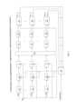
Сущность предлагаемого изобретения поясняется структурной схемой, приведенной на фиг. 2, где обозначено:The essence of the invention is illustrated by the block diagram shown in Fig. 2, where it is indicated:
1, 2, 3 - аналого-цифровые преобразователи сигналов входных каналов (0 ≤ i ≤ Ne - 1);1, 2, 3 - analog-to-digital signal converters of input channels (0 ≤ i ≤ Ne - 1);
4, 5, 6 - цифровые формирователи квадратурных составляющих сигналов входных каналов (0 ≤ i ≤ Ne - 1);4, 5, 6 - digital shapers of the quadrature components of the signals of the input channels (0 ≤ i ≤ Ne - 1);
7, 8, 9 - объединенные фильтры отсчетов сигналов входных каналов (0 ≤ i ≤ iVe - 1);7, 8, 9 - combined filters of samples of signals of input channels (0 ≤ i ≤ iVe - 1);
10 - формирователь характеристики направленности с весовой обработкой в пространственной области;10 - shaper directivity with weight processing in the spatial domain;
11, 12, 13 - вычислители модулей отсчетов сигналов пространственных каналов (0 ≤ m ≤ Nb - 1);11, 12, 13 - calculators of sample modules of signals of spatial channels (0 ≤ m ≤ Nb - 1);
14, 15, 16 - определители моментов максимума отсчетов сигналов пространственных каналов (0 ≤ m ≤ Nb - 1);14, 15, 16 - determinants of the moments of the maximum readings of the signals of the spatial channels (0 ≤ m ≤ Nb - 1);
17, 18, 19 - вычислители параметров объектов пространственных каналов (0 ≤ m ≤ Nb - 1);17, 18, 19 - calculators of parameters of objects of spatial channels (0 ≤ m ≤ Nb - 1);
20 - блок выбора объекта.20 - object selection block.
В ВСГЛ с повышенным ОСШ и разрешением по дальности используется 3 периода зондирования. Первое и второе зондирование применяются для определения скорости движущихся подводных объектов, а третье - для определения дальности до выбранного движущегося объекта с повышенным ОСШ и разрешением. ВСГЛ работает следующим образом.In HSRL with enhanced SNR and range resolution, 3 sounding periods are used. The first and second soundings are used to determine the speed of moving underwater objects, and the third one is used to determine the range to the selected moving object with increased SNR and resolution. VSGL works as follows.
Принятые в Ne входных каналах аналоговые эхосигналы x(t), представляющие собой периодические последовательности ЛЧМ радиоимпульсов с череспериодным изменением знака девиации частоты, преобразовываются в каждом из Ne АЦП 1, 2, 3 в отсчеты х(nТ) с периодом дискретизации Т и подаются в Ne ЦФКС 4, 5, 6, устройство и принцип работы которых подробно описаны в [5, 6]. В ЦФКС 4, 5, 6 отсчеты сигнала преобразуются в отсчеты КО входного сигнала с периодом дискретизации Т1.The analog echo signals x(t) received in Ne input channels, which are periodic sequences of chirp radio pulses with an interperiod change in the sign of the frequency deviation, are converted in each of Ne ADCs 1, 2, 3 into samples x(nT) with a sampling period T and are fed in Ne CFKS 4, 5, 6, the device and principle of operation of which are described in detail in [5, 6]. In
Отсчеты КО каждого из Ne входного канала поступают в ОФ 7, 8, 9, реализующие функции СФ и ЦФ, структура которых описана в [5]. При этом, во время четных зондирований сигналы подаются в СФ с передаточной функцией Н1(k) для согласованной обработки ЛЧМ сигналов с положительным знаком девиации частоты, а при нечетных зондированиях эхосигналы поступают в СФ с передаточной функцией Н2(k) для согласованной обработки ЛЧМ сигналов с отрицательной девиацией частоты. Импульсные характеристики СФ, соответствующие передаточным функциям Н1(k) и Н2(k), хранятся в памяти устройства и по сигналу управления используются в ОФ 7, 8, 9. После ЦФ над выходными сигналами выполняется операция децимации, снижающая частоту следования отсчетов до Т2.The QoS readings of each of the Ne input channels are sent to
Выходные сигналы ОФ 7, 8, 9 поступают в ФХН 10.Output signals OF 7, 8, 9
Процедура ФХН выполняется во временной области фазовым методом, который заключается в компенсации разностей фаз (для несущей частоты) выходных сигналов элементов, возникающих из-за задержки моментов поступления фронта принимаемой волны на эти элементы. При этом формирование каждого из лучей сводится к суммированию отсчетов КО выходных сигналов всех элементов с соответствующими фазовыми сдвигами и результатом формирования ХН (выходным сигналом в каждом из Nb пространственных каналов) является дискретный сигнал в виде последовательности комплексных отсчетов Процедура ФХН выполняется одновременно с ВО по пространству для уменьшения уровня боковых лепестков в ХН.The FHN procedure is performed in the time domain by the phase method, which consists in compensating for the phase differences (for the carrier frequency) of the output signals of the elements that arise due to the delay in the moments when the front of the received wave arrives at these elements. In this case, the formation of each of the beams is reduced to the summation of the readings of the CO output signals of all elements with the corresponding phase shifts and the result of the formation of XH (the output signal in each of the Nb spatial channels) is a discrete signal in the form of a sequence of complex readings The FHN procedure is performed simultaneously with the VO in space to reduce the level of side lobes in the HN.
Затем в ВМ 11, 12, 13 вычисляются модули выходных сигналов всех пространственных каналов M(nT2).Then, in the
Отсчеты модулей сигналов М(nТ2) в каждом пространственном канале поступают на входы ОММ 14, 15, 16, содержащие пороговые устройства, необходимые для принятия решения об обнаружении объектов, и определяющие моменты запаздывания максимальных сигналов огибающих nmах0Т2 и nmах1Т2, поступивших в первом и втором периодах зондирования соответственно.The readings of the signal modules M(nT2 ) in each spatial channel are fed to the inputs of the
Измеренные значения запаздывания nmах0Т2 и nmах1T2 поступают в каждом пространственном канале в соответствующий ВПО 17, 18, 19, где в соответствии с командами управления в нечетные периоды излучения ЛЧМ сигналов определяется дальность и скорости цели. Полученная в каждом ВПО информация о скорости цели поступает на входы БВО 20, где рассчитывается доплеровская частота целей. На дополнительный вход БВО 20 подается информация о выборе объекта, в результате чего из блока выдается доплеровская частота, соответствующая эхосигналу от выбранного в определенном канале движущегося объекта (цели). Данное значение поступает на вторые входы ЦФКС 4, 5, 6, где формируются КО сигналов.The measured delay values nmax0 T2 and nmax1 T2 are received in each spatial channel in the corresponding
В третьем периоде зондирования после компенсации доплеровского сдвига частоты в принятом эхосигнале от движущегося объекта центр спектра полученной КО находится точно на нулевой частоте и не имеет доплеровского смещения частоты. Поэтому предварительно рассчитанные и созданные СФ в ОФ 7, 8, 9 оказываются полностью согласованными с КО полученных сигналов. Это приводит к увеличению ОСШ и улучшению разрешения по дальности.In the third probing period, after compensation for the Doppler frequency shift in the received echo signal from a moving object, the center of the spectrum of the received CO is exactly at zero frequency and does not have a Doppler frequency shift. Therefore, the pre-calculated and created SFs in
Таким образом, изобретение представляет собой ВСГЛ, обеспечивающий повышенное ОСШ и разрешение по дальности.Thus, the invention is an HLL providing improved SNR and range resolution.
Источники информацииInformation sources
1. Патент 5390152 А США, МПК G01S 15/89, Forward looking echosounder. Заявл. 18.11.1993. Опубл. 14.02.1995.1. US Patent 5390152 A,
2. Патент 8203909 В1 США, МПК G01S 15/88, Forward-looking sonar for ships and boats. Заявл. 10.05.2010. Опубл. 19.07.2012.2. Patent 8203909 B1 USA,
3. Маркович И.И. Методы и алгоритмы цифровой пространственно-временной обработки гидроакустических сигналов в многолучевых эхолотах и локаторах препятствий // Фундаментальная и прикладная гидрофизика - СПб: Наука, 2014. - Т. 7. - №2. - С.58-71.3. Markovich I.I. Methods and algorithms for digital space-time processing of hydroacoustic signals in multi-beam echo sounders and obstacle locators // Fundamental and applied hydrophysics - St. Petersburg: Nauka, 2014. - V. 7. - No. 2. - P.58-71.
4. Патент 2699938 С1, Российская Федерация, МПК G01S 15/00. Впередсмотрящий гидролокатор глубоководного носителя. №2019101013. Заявл.: 10.01.2019. Опубл. 11.09.2019. Бюл. №26./ И.И. Маркович, В.В. Колган. Заявитель и патентообладатель - Российская Федерация, от имени которой выступает Министерство обороны РФ.4. Patent 2699938 C1, Russian Federation,
5. Маркович И.И. Цифровая обработка сигналов в системах и устройствах: монография. - Ростов н/Д: Изд-во ЮФУ, 2012. - 236 с.5. Markovich I.I. Digital signal processing in systems and devices: monograph. - Rostov n / a: Publishing House of the Southern Federal University, 2012. - 236 p.
6. Маркович И.И. Реализация алгоритмов цифрового формирования квадратурных составляющих в локационных комплексах различного назначения // Вестник компьютерных и информационных технологий. - 2006. - №6. - С.16-21.6. Markovich I.I. Implementation of algorithms for the digital formation of quadrature components in location complexes for various purposes // Bulletin of Computer and Information Technologies. - 2006. - No. 6. - P.16-21.
7. Найт У.С., Придэм Р.Г., Кэй СМ. Цифровая обработка сигналов в гидролокационных системах // ТИИЭР. 1981. - Т. 69, - №11. - С.84-155.7. Knight W.S., Pridem R.G., Kay SM. Digital signal processing in sonar systems // TIIER. 1981. - T. 69, - No. 11. - P.84-155.
8. Маркович И.И. Цифровая пространственно-временная обработка сигналов в многолучевом гидролокаторе морского подводного робототехнического комплекса // «Известия ЮФУ. Технические науки», 2019. - №1(203).- С.239-248.8. Markovich I.I. Digital space-time signal processing in a multi-beam sonar of a marine underwater robotic complex // Izvestiya SFU. Engineering Sciences", 2019. - No. 1 (203). - P. 239-248.
Claims (1)
Translated fromRussianPublications (1)
| Publication Number | Publication Date |
|---|---|
| RU2802295C1true RU2802295C1 (en) | 2023-08-24 |
Family
ID=
Citations (5)
| Publication number | Priority date | Publication date | Assignee | Title |
|---|---|---|---|---|
| US6842401B2 (en)* | 2000-04-06 | 2005-01-11 | Teratech Corporation | Sonar beamforming system |
| CN109725650A (en)* | 2019-03-08 | 2019-05-07 | 哈尔滨工程大学 | An AUV Obstacle Avoidance Method in Dense Obstacle Environment |
| RU2699938C1 (en)* | 2019-01-10 | 2019-09-11 | Российская Федерация, от имени которой выступает Министерство обороны Российской Федерации | Deep-sea carrier forward sonar |
| US20200174109A1 (en)* | 2018-11-30 | 2020-06-04 | Navico Holding As | Systems and associated methods for monitoring vessel noise level |
| GB2601718A (en)* | 2008-11-21 | 2022-06-15 | Thales Holdings Uk Plc | Method and system for detecting sonar system |
Patent Citations (5)
| Publication number | Priority date | Publication date | Assignee | Title |
|---|---|---|---|---|
| US6842401B2 (en)* | 2000-04-06 | 2005-01-11 | Teratech Corporation | Sonar beamforming system |
| GB2601718A (en)* | 2008-11-21 | 2022-06-15 | Thales Holdings Uk Plc | Method and system for detecting sonar system |
| US20200174109A1 (en)* | 2018-11-30 | 2020-06-04 | Navico Holding As | Systems and associated methods for monitoring vessel noise level |
| RU2699938C1 (en)* | 2019-01-10 | 2019-09-11 | Российская Федерация, от имени которой выступает Министерство обороны Российской Федерации | Deep-sea carrier forward sonar |
| CN109725650A (en)* | 2019-03-08 | 2019-05-07 | 哈尔滨工程大学 | An AUV Obstacle Avoidance Method in Dense Obstacle Environment |
Similar Documents
| Publication | Publication Date | Title |
|---|---|---|
| US6130641A (en) | Imaging methods and apparatus using model-based array signal processing | |
| US11668820B2 (en) | Sonar data compression | |
| US7852709B1 (en) | Sonar system and process | |
| EP0010974B1 (en) | Velocity measuring correlation sonar apparatus | |
| WO2008105932A2 (en) | System and method for forward looking sonar | |
| CA2775115A1 (en) | Method and device for measuring a contour of the ground | |
| RU2225991C2 (en) | Navigation sonar to illuminate near situation | |
| US5305286A (en) | Bistatic/monostatic sonar fence | |
| US5237541A (en) | Platform carried bistatic sonar | |
| Bjørnø | Developments in sonar and array technologies | |
| WO2017158659A1 (en) | Acoustic measurement device, acoustic measurement method, shaking component detection device, shaking component detection method, multi-beam acoustic measurement device, and synthetic aperture sonar | |
| EP0685076B1 (en) | Signal processing system and method for use in multi beam sensing systems | |
| US5812494A (en) | Wide-angle, forward-looking bathymetric mapping | |
| US5235558A (en) | Choke point bistatic sonar | |
| EP3171200B1 (en) | Low-cost underwater acoustic system for real-time three-dimensional imaging | |
| EP2317335B1 (en) | Improved beamforming method for analysing signals received by a transducer arrray, and relative detection system | |
| RU2802295C1 (en) | Forward-looking sonar with increased range resolution | |
| RU178905U1 (en) | MULTI-BEAM SCIENTIFIC ECHO SOUNDER FOR ACCOUNTING WATER BIORESOURCES | |
| Tinh | Investigation on beamforming solution for multi-receiver synthetic aperture sonar using CW pulse with sound velocity profiles in Vietnam’s sea | |
| US6847588B1 (en) | Method for changing the frequency for sampling sonar wavefronts | |
| RU2699938C1 (en) | Deep-sea carrier forward sonar | |
| WO2011058527A1 (en) | Method and apparatus for processing sonar signals | |
| Bjørnø | Developments in sonar technologies and their applications | |
| JP2001174543A (en) | Active sonar device and active sonar method | |
| Barbu et al. | AQS-20 sonar processing enhancement for bathymetry estimation |