RU2775839C1 - Method for injecting a mixture into an oil and gas well and a set of equipment - hydraulic fracturing fleet according to this method - Google Patents
Method for injecting a mixture into an oil and gas well and a set of equipment - hydraulic fracturing fleet according to this methodDownload PDFInfo
- Publication number
- RU2775839C1 RU2775839C1RU2021124315ARU2021124315ARU2775839C1RU 2775839 C1RU2775839 C1RU 2775839C1RU 2021124315 ARU2021124315 ARU 2021124315ARU 2021124315 ARU2021124315 ARU 2021124315ARU 2775839 C1RU2775839 C1RU 2775839C1
- Authority
- RU
- Russia
- Prior art keywords
- gel
- hydraulic fracturing
- fracturing fleet
- control system
- hydration
- Prior art date
Links
- 238000000034methodMethods0.000titleclaimsabstractdescription49
- 239000000203mixtureSubstances0.000titleclaimsabstractdescription34
- 230000036571hydrationEffects0.000claimsabstractdescription39
- 238000006703hydration reactionMethods0.000claimsabstractdescription39
- 239000000126substanceSubstances0.000claimsabstractdescription20
- 239000000654additiveSubstances0.000claimsabstractdescription13
- 238000005086pumpingMethods0.000claimsabstractdescription12
- 239000007788liquidSubstances0.000claimsdescription11
- XLYOFNOQVPJJNP-UHFFFAOYSA-NwaterSubstancesOXLYOFNOQVPJJNP-UHFFFAOYSA-N0.000claimsdescription8
- 230000000996additive effectEffects0.000claimsdescription6
- 238000002347injectionMethods0.000claimsdescription6
- 239000007924injectionSubstances0.000claimsdescription6
- 239000003153chemical reaction reagentSubstances0.000claimsdescription5
- 238000010438heat treatmentMethods0.000claimsdescription4
- 239000012530fluidSubstances0.000claimsdescription2
- 239000004215Carbon black (E152)Substances0.000abstractdescription5
- 229930195733hydrocarbonNatural products0.000abstractdescription5
- 150000002430hydrocarbonsChemical class0.000abstractdescription5
- 239000003129oil wellSubstances0.000abstractdescription3
- 238000004886process controlMethods0.000abstract1
- 238000010586diagramMethods0.000description10
- 239000013590bulk materialSubstances0.000description4
- 239000000463materialSubstances0.000description3
- 238000010835comparative analysisMethods0.000description2
- 239000003431cross linking reagentSubstances0.000description2
- 239000003349gelling agentSubstances0.000description2
- 238000009434installationMethods0.000description1
- 238000012544monitoring processMethods0.000description1
- 239000002689soilSubstances0.000description1
- 239000000243solutionSubstances0.000description1
Images


Abstract
Description
Translated fromRussianДанное предлагаемое изобретение относится к нефтедобывающей промышленности и может быть использовано для проведения работ по стимуляции нефтедобывающих скважин с трудно извлекаемым запасом углеводородов.This invention relates to the oil industry and can be used to stimulate oil wells with hard-to-recover hydrocarbon reserves.
Анализ показал, что число нефтедобывающих скважины с трудно извлекаемым запасом углеводородов, расположенных на территории РФ, из года в год возрастает.The analysis showed that the number of oil wells with hard-to-recover hydrocarbon reserves located on the territory of the Russian Federation is increasing from year to year.
Для стимуляции таких нефтедобывающих скважин флот ГРП должен обеспечить возможность подачи более 400 тонн пропанта за один ГРП с концентрацией до 2000 кг/м3, с максимальным давлением закачиваемого раствора на устье скважины до 105 МПа и переменным расходом от 0,2 до 16 м3/мин.To stimulate such oil-producing wells, the hydraulic fracturing fleet must provide the possibility of supplying more than 400 tons of proppant per hydraulic fracturing with a concentration of up to 2000 kg/m3 , with a maximum pressure of the injected solution at the wellhead up to 105 MPa and a variable flow rate from 0.2 to 16 m3 / min.
В качестве прототипа к заявляемому способу нагнетания смеси в нефтегазовую скважину известен способ смешение флюида на «лету», т.е. проводят приготовление геля из подаваемой на вход гидратационной установки воды из технологических емкостей и реагентов от установки химических добавок, перекачку геля на вход миксера смесительной установки, где выполняется смешивание геля с пропантом и химическими добавками до получения контролируемой концентрации, подачу полученной смеси к входам насосных установок и нагнетание ее в скважину [1].As a prototype for the claimed method of injecting a mixture into an oil and gas well, a method is known for mixing fluid on the fly, i.e. the gel is prepared from the water supplied to the inlet of the hydration plant from process tanks and reagents from the chemical additives plant, the gel is pumped to the mixer inlet of the mixing plant, where the gel is mixed with proppant and chemical additives until a controlled concentration is obtained, the resulting mixture is supplied to the inlets of pumping units and its injection into the well [1].
Недостатком этого способа является то, что для флота ГРП, с указанными характеристиками, требуется разработать гидратационную установку с повышенной производительностью или устанавливать дополнительные аналогичные гидратационные установки из имеющего оборудования.The disadvantage of this method is that for the hydraulic fracturing fleet with the specified characteristics, it is required to develop a hydration unit with increased productivity or install additional similar hydration units from existing equipment.
В качестве прототипа флота ГРП для реализации способа нагнетания смеси в нефтегазовую скважину выбран флот, включающий в себя насосные установки, нагнетающие в скважину смесь по программе системы управления флота ГРП, соединенные нагнетательным манифольдом с миксером смесительной установки, который соединен с выходом насоса гидратационной установки [1].As a prototype of the hydraulic fracturing fleet for implementing the method of injecting the mixture into an oil and gas well, a fleet was chosen, including pumping units that inject the mixture into the well according to the program of the hydraulic fracturing fleet control system, connected by an injection manifold to a mixing unit mixer, which is connected to the pump outlet of the hydration unit [1 ].
К недостатку прототипа флота ГРП можно отнести замечания, изложенные к способу.The disadvantage of the prototype hydraulic fracturing fleet can be attributed to the comments set out to the method.
Технической задачей изобретения является увеличение производительности флота ГРП и повышение его эффективности при заданных габаритах и технологических ограничениях.The technical objective of the invention is to increase the productivity of the hydraulic fracturing fleet and increase its efficiency with given dimensions and technological limitations.
Указанная техническая задача решается тем, что в известном способе нагнетания смеси из сыпучих и жидких химических реагентов в нефтегазовую скважину, по которому на основе программы системы управления флота ГРП проводят приготовление геля из подаваемой на входы гидратационной установки воды из технологических емкостей и реагентов от установки химических добавок, перекачку геля на вход миксера смесительной установки, где выполняется смешивание геля с пропантом и химическими добавками до получения контролируемой программой системы управления флота ГРП концентрации, подачу полученной смеси к входам насосных установок и нагнетание ее в скважину, согласно изобретению предварительно часть технологических емкостей от гидратационной установки заполняют гелем, который подается в миксер смесительной установки параллельно с гелем от гидратационной установки, а совместная работа насосов этих установок обеспечивается системой автоматизированного управления флота ГРП, выполняющей функции системы автоматического регулирования технологическими процессами.The specified technical problem is solved by the fact that in the known method of injecting a mixture of bulk and liquid chemicals into an oil and gas well, according to which, on the basis of the hydraulic fracturing fleet control system program, the gel is prepared from the water supplied to the inlets of the hydration unit from process tanks and reagents from the chemical additive unit , pumping the gel to the inlet of the mixer of the mixing plant, where the gel is mixed with proppant and chemical additives until a program-controlled hydraulic fracturing fleet control system is obtained, the resulting mixture is fed to the inlets of pumping units and injected into the well, according to the invention, a preliminary part of the process tanks from the hydration unit filled with gel, which is fed into the mixer of the mixing unit in parallel with the gel from the hydration unit, and the joint operation of the pumps of these units is ensured by the automatic control system of the hydraulic fracturing fleet, which performs the functions of an automatic automatic control of technological processes.
Указанная техническая задача решается тем, что для реализации способа нагнетания смеси из сыпучих и жидких химических реагентов в нефтегазовую скважину флот ГРП, включающий в себя нагнетающие в скважину смесь по программе системы управления флота ГРП насосные установки, соединенные нагнетательным манифольдом с миксером смесительной установки, согласно изобретению, миксер смесительной установки своим входом параллельно соединен с одной стороны с выходом подключенного к предварительно заполненным гелем технологическим емкостям собственного всасывающего насоса, а с другой стороны с выходом насоса гидратационной установки, причем выходы этих насосов снабжены заслонками и расходомерами для регулирования расхода геля при совместной работе по командам системы управления флота ГРП.This technical problem is solved by the fact that in order to implement a method for injecting a mixture of bulk and liquid chemicals into an oil and gas well, the hydraulic fracturing fleet, which includes pumping units injecting the mixture into the well according to the program of the hydraulic fracturing fleet control system, connected by an injection manifold to a mixing unit mixer, according to the invention , the mixing plant mixer is connected in parallel with its inlet to the output of its own suction pump connected to the process tanks pre-filled with gel, and on the other hand to the output of the hydration plant pump, and the outputs of these pumps are equipped with dampers and flow meters to regulate the flow of gel when working together teams of the hydraulic fracturing fleet management system.
Указанная цель достигается также тем, что технологические емкости связаны с гидратационной и смесительной установками через манифольд низкого давления, который при низких температурах окружающей среды может быть дополнительно подключен к машине подогрева жидкости.This goal is also achieved by the fact that the process tanks are connected to the hydration and mixing plants through a low pressure manifold, which at low ambient temperatures can be additionally connected to the liquid heating machine.
Указанная цель достигается также тем, что расход геля q при совместной работе насосов смесительной и гидратационной установок, составляет q≥16 м3 /мин.This goal is also achieved by the fact that the flow rate of the gel q during the joint operation of the pumps of the mixing and hydration plants is q≥16 m3 /min.
Указанная цель достигается также тем, что технологические емкости для заполнения гелем имеют общий объем V>400 м3.This goal is also achieved by the fact that technological containers for filling with gel have a total volume of V>400 m3 .
Сопоставительный анализ заявляемого способа нагнетания смеси из сыпучих и жидких химических реагентов в нефтегазовую скважину с прототипом показывает, что заявляемый способ отличается тем, что предварительно часть технологических емкостей от гидратационной установки заполняют гелем, который подается в миксер смесительной установки параллельно с гелем от гидратационной установки, а совместная работа насосов этих установок обеспечивается системой автоматизированного управления флота ГРП, выполняющей функции системы автоматического регулирования технологическими процессами.A comparative analysis of the proposed method for injecting a mixture of bulk and liquid chemicals into an oil and gas well with a prototype shows that the proposed method differs in that part of the process tanks from the hydration unit is preliminarily filled with gel, which is fed into the mixer of the mixing unit in parallel with the gel from the hydration unit, and the joint operation of the pumps of these units is provided by the automatic control system of the hydraulic fracturing fleet, which performs the functions of an automatic control system for technological processes.
Сопоставительный анализ заявляемого флота ГРП с прототипом показывает, что заявляемый флот ГРП отличается тем, что миксер смесительной установки своим входом параллельно соединен с одной стороны с выходом подключенного к предварительно заполненным гелем технологическим емкостям собственного всасывающего насоса, а с другой стороны с выходом насоса гидратационной установки, причем выходы этих насосов снабжены заслонками и расходомерами для регулирования расхода геля при совместной работе по командам системы управления флота ГРП.Comparative analysis of the proposed hydraulic fracturing fleet with the prototype shows that the proposed hydraulic fracturing fleet differs in that the mixer of the mixing plant is connected in parallel with its inlet on one side to the outlet of its own suction pump connected to the process tanks pre-filled with gel, and on the other hand to the outlet of the hydration unit pump, moreover, the outputs of these pumps are equipped with dampers and flow meters to control the flow of gel when working together on commands from the hydraulic fracturing fleet control system.
Отличается также тем, что технологические емкости связаны с гидратационной и смесительной установками через манифольд низкого давления, который при низких температурах окружающей среды может быть дополнительно подключен к машине подогрева жидкости.It also differs in that the technological tanks are connected to the hydration and mixing plants through a low-pressure manifold, which at low ambient temperatures can be additionally connected to the liquid heating machine.
Отличается также тем, что расход геля q при совместной работе насосов смесительной и гидратационной установок, составляет q≥16 м3/мин.It also differs in that the gel flow rate q during the joint operation of the pumps of the mixing and hydration plants is q≥16 m3 /min.
Отличается также тем, что технологические емкости для заполнения гелем имеют общий объем V>400 м3.It also differs in that the technological containers for filling with gel have a total volume of V>400 m3 .
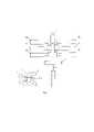
На фиг. 1 показана схема из прототипа, поясняющая способ нагнетания смеси из сыпучих и жидких химических реагентов в нефтегазовую скважину, где подача геля в смесительную установку осуществляется непосредственно из гидратационной установки.In FIG. 1 shows a diagram from the prototype, explaining the method of injecting a mixture of bulk and liquid chemicals into an oil and gas well, where the gel is supplied to the mixing unit directly from the hydration unit.
На фиг. 2 показана схема, в соответствии с которой проводится предварительная операция по заполнению технологических емкостей гелем от гидратационной установки.In FIG. 2 shows a scheme in accordance with which a preliminary operation is carried out to fill the process tanks with gel from the hydration unit.
На фиг. 3 показана схема аналога [1], поясняющая способ нагнетания смеси из сыпучих и жидких химических реагентов в нефтегазовую скважину, где подача геля в смесительную установку осуществляется из предварительно заполненных гелем технических емкостей в соответствии со схемой, приведенной на фиг. 2.In FIG. Figure 3 shows a diagram of an analogue [1], which explains the method of injecting a mixture of bulk and liquid chemicals into an oil and gas well, where the gel is supplied to the mixing plant from technical tanks pre-filled with gel in accordance with the diagram shown in FIG. 2.
На фиг. 4 приведена схема, поясняющая способ нагнетания смеси из сыпучих и жидких химических реагентов в нефтегазовую скважину, в соответствии с формулой изобретения.In FIG. 4 is a diagram illustrating a method for injecting a mixture of bulk and liquid chemicals into an oil and gas well, in accordance with the claims.
На фиг. 5 приведен флот ГРП в соответствии с формулой изобретения.In FIG. 5 shows the hydraulic fracturing fleet in accordance with the claims.
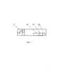
На фиг. 6 приведена детализация позиции 4 фиг. 5.In FIG. 6 shows the details of
На схеме, фиг. 1, вода из технологических емкостей 1 через манифольд низкого давления 2 и реагенты из установки химических добавок (на фиг. 1 установка химических добавок не показана) поступают в гидратационную установку 3, где добавки, гелирующие и сшивающие реагенты перемешиваются с водой с образованием геля. Гель насосом гидратационной установки (на фиг. 1 насос гидратационной установки не показан) подается в смесительную установку 4. В смесительной установке 4 выполняется смешивание геля с пропантом, поступющим из машины подачи сыпучих материалов (на фиг. 1 машина подачи сыпучих материалов не показана), до получения контролируемой концентрации. Смесь из смесительной установки 4 подается на входы низкого давления блока манифольда напорного 5 (на фиг. 1 все соединения входа низкого давления блока манифольда напорного 5 показаны тонкой линией). Смесь с выходов установок насосных 6 подается на входы высокого давления блока манифольда напорного 5 (на фиг. 1 вход высокого давления блока манифольда напорного 5 показан толстой линией). Смесь с выхода высокого давления блока манифольда напорного 5 нагнетается в нефтегазовую скважину 7.In the diagram, Fig. 1, water from
На схеме, фиг. 2, вода из бассейна (на фиг. 2 бассейн не показан) и реагенты из установки химических добавок (на фиг. 2 установка химических добавок не показана) поступают в гидратационную установку 3, где добавки, гелирующие и сшивающие реагенты перемешиваются с водой с образованием геля. Гель насосом гидратационной установки (на фиг. 2 насос гидратационной установки не показан) подается в технологические емкости 1 через манифольд низкого давления 2.In the diagram, Fig. 2, water from the pool (the pool is not shown in Fig. 2) and reagents from the chemical additive unit (the chemical additive unit is not shown in Fig. 2) enter the
На схеме, фиг. 3, гель из технологических емкостей подается в смесительную установку 4 через манифольд низкого давления 2 насосами смесительной установки (на фиг. 3 насосы смесительной установки не показаны). В смесительной установке 4 выполняется смешивание геля с пропантом, поступающим из машины подачи сыпучих материалов (на фиг. 3 машина подачи сыпучих материалов не показана), до получения контролируемой концентрации. Смесь из смесительной установки 4 подается на входы низкого давления блока манифольда напорного 5 (на фиг. 3 все соединения входа низкого давления блока манифольда напорного 5 показаны тонкой линией). Смесь с выходов установок насосных 6 подается на входы высокого давления блока манифольда напорного 5 (на фиг. 1 вход высокого давления блока манифольда напорного 5 показан толстой линией). Смесь с выхода высокого давления блока манифольда напорного 5 нагнетается в нефтегазовую скважину 7.In the diagram, Fig. 3, the gel from the process tanks is fed into the
Очевидно, что для способа нагнетания смеси в нефтегазовую скважину, приведенного на фиг. 1, для повышения производительности нагнетания смеси в нефтегазовую скважину с трудно извлекаемым запасом углеводородов требуется устанавливать дополнительные гидратационные установки, которые работая в параллель, обеспечивали бы требуемый расход смеси. При этом потребуется увеличить площадь площадки для размещения такого флота ГРП. Либо разрабатывать гидратационные установки с повышенной производительностью. Аналогичные требования предъявляются и к смесительной установке при реализации способа нагнетания смеси в нефтегазовую скважину, приведенного на фиг. 3.Obviously, for the method of injecting a mixture into an oil and gas well, shown in FIG. 1, in order to increase the productivity of the injection of the mixture into an oil and gas well with a hard-to-recover hydrocarbon reserve, it is required to install additional hydration units that, working in parallel, would provide the required flow rate of the mixture. At the same time, it will be necessary to increase the area of the site to accommodate such a hydraulic fracturing fleet. Or develop hydration units with increased productivity. Similar requirements are imposed on the mixing plant when implementing the method of injecting the mixture into an oil and gas well, shown in Fig. 3.
На схеме, фиг. 4,. после подготовительной операции по заполнению гелем технологических емкостей 1 через манифольд низкого давления 2, как показано на схеме фиг. 2, гель из заполненных технологических емкостей подается в смесительную установку 4 ее собственными насосами (на фиг. 2 насосы смесительной установки не показаны) через манифольд низкого давления 2, при этом параллельно гель из гидратационной установки 3 ее собственными насосами подается в смесительную установку 4. Совместная работа насосов этих установок обеспечивается системой управления флота ГРП, выполняющая функции системы автоматического регулирования технологическими процессами. В смесительной установке 4 выполняется смешивание геля с пропантом, поступающим из машины подачи сыпучих материалов (на фиг. 4 машина подачи сыпучих материалов не показана) до получения контролируемой концентрации. Смесь из смесительной установки подается на входы низкого давления блока манифольда напорного 5 (на фиг. 4 все соединения входа низкого давления блока манифольда напорного 5 показаны тонкой линией). Смесь с выходов установок насосных 6 подается на входы высокого давления блока манифольда напорного 5 (на фиг. 4 вход высокого давления блока манифольда напорного 5 показан толстой линией). Смесь с выхода высокого давления блока манифольда напорного 5 нагнетается в нефтегазовую скважину 7.In the diagram, Fig. four,. after the preparatory operation for filling the
Как видно, способ нагнетания смеси в нефтегазовую скважину, приведенный на схеме фиг. 4, позволяет увеличить производительность флота ГРП без увеличения мощности имеющегося флота и его номенклатуры, который может быть применен при обслуживании нефтегазовых скважин с трудно извлекаемым запасом углеводородов.As can be seen, the method of injecting the mixture into an oil and gas well, shown in the diagram of Fig. 4 makes it possible to increase the productivity of the hydraulic fracturing fleet without increasing the capacity of the existing fleet and its range, which can be used in servicing oil and gas wells with hard-to-recover hydrocarbon reserves.
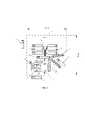
На фиг. 5 показан флот ГРП, применяемый для реализации способа нагнетания смеси из сыпучих и жидких химических реагентов в нефтегазовую скважину, включающий в себя нагнетающие в скважину смесь по программе системы управления флота ГРП насосные установки 6, соединенные нагнетательным манифольдом 5 с миксером смесительной установки 4, миксер смесительной установки 4 своим входом параллельно соединен с одной стороны с выходом подключенного к предварительно заполненным гелем технологическим емкостям 1 собственного всасывающего насоса 14, фиг. 6, а с другой стороны с выходом насоса гидратационной установки 3 (на фиг. 5 насос гидратационной установки не показан), причем выходы этих насосов снабжены заслонками 15. фиг. 6, и расходомерами 16, фиг. 6, для регулирования расхода геля при совместной работе по командам системы управления флота ГРП. Также на фиг. 5 показаны машины подачи сыпучих материалов 9, машина системы автоматизированного управления и контроля 11, машина подготовки воды 12 и машина манифольдов 13.In FIG. 5 shows the hydraulic fracturing fleet used to implement the method of injecting a mixture of bulk and liquid chemicals into an oil and gas well, including
Для нормальной работы всех систем флота ГРП площадка, на которой устанавливается флот ГРП, подготавливается в инженерном отношении, а именно: - уклон плоскости площадки составляет не более 2°; - грунт уплотняется в обеспечение допустимого давления давление 3 кгс/см2. Учитывая при этом, что скважина может находиться в болотистой местности, площадку желательно иметь минимального размера.For the normal operation of all systems of the hydraulic fracturing fleet, the site on which the hydraulic fracturing fleet is installed is prepared in engineering terms, namely: - the slope of the site plane is no more than 2°; - the soil is compacted to provide an allowable pressure of 3 kgf/cm2 . Given the fact that the well may be located in a swampy area, it is desirable to have a site of a minimum size.
В зимнее время технологические емкости, связанные с гидратационной и смесительной установками через манифольд низкого давления, который при низких температурах окружающей среды может быть дополнительно подключен к машине подогрева жидкости 10, фиг. 5. Это повышает эффективность использования флота ГРП.In winter, process tanks connected to the hydration and mixing plants through a low-pressure manifold, which at low ambient temperatures can be additionally connected to the
Расход геля q при совместной работе насосов смесительной и гидратационной установок, составляет q≥16 м3 /мин, что указывает на повышение производительности флота ГРП при заданных его габаритах.The gel flow rate q during joint operation of the pumps of the mixing and hydration units is q≥16 m3 /min, which indicates an increase in the productivity of the hydraulic fracturing fleet with its given dimensions.
То, что технологические емкости для заполнения гелем имеют общий объем V>400 м3 позволяет реализовать повышение производительности флота ГРП при заданных его габаритах.The fact that technological tanks for filling with gel have a total volume of V>400 m3 makes it possible to increase the productivity of the hydraulic fracturing fleet with its given dimensions.
Таким образом, все отличительные признаки способа нагнетания смеси в нефтегазовую скважину и комплекс оборудования (флот ГРП) позволяют увеличить производительности флота ГРП, повысить его эффективности при заданных габаритах и технологических ограничениях.Thus, all the distinguishing features of the method of injecting the mixture into an oil and gas well and a set of equipment (fracturing fleet) allow increasing the productivity of the hydraulic fracturing fleet, increasing its efficiency with given dimensions and technological limitations.
1. М. Экономидес, Р. Олини, П. Валько УНИФИЦИРОВАННЫЙ ДИЗАЙН ГИДРОРАЗРЫВА ПЛАСТА: ОТ ТЕОРИИ К ПРАКТИКЕ, АНО «Институт компьютерных исследований», г. Ижевск, 2007, 236 с.1. M. Economides, R. Olini, P. Valko UNIFIED HYDRAULIC FRACTURING DESIGN: FROM THEORY TO PRACTICE, Institute for Computer Research, Izhevsk, 2007, 236 p.
Claims (5)
Translated fromRussianPublications (1)
| Publication Number | Publication Date |
|---|---|
| RU2775839C1true RU2775839C1 (en) | 2022-07-11 |
Family
ID=
Citations (6)
| Publication number | Priority date | Publication date | Assignee | Title |
|---|---|---|---|---|
| US8360152B2 (en)* | 2008-10-21 | 2013-01-29 | Encana Corporation | Process and process line for the preparation of hydraulic fracturing fluid |
| RU127656U1 (en)* | 2012-10-12 | 2013-05-10 | Совместное закрытое акционерное общество "ФИДМАШ" | HYDRATION INSTALLATION |
| RU131803U1 (en)* | 2013-02-12 | 2013-08-27 | Совместное закрытое акционерное общество "ФИДМАШ" | INSTALLATION OF CONTROL AND CONTROL OF THE PROCESS OF HYDRAULIC BREAKING |
| RU2692297C2 (en)* | 2014-05-12 | 2019-06-24 | Шлюмбергер Текнолоджи Б.В. | Integrated supply in process at drilling site |
| RU2706041C2 (en)* | 2014-11-18 | 2019-11-13 | ВЕЗЕРФОРД ТЕКНОЛОДЖИ ХОЛДИНГЗ, ЭлЭлСи | Systems and methods for optimizing formation fracturing operations |
| RU2747277C2 (en)* | 2016-09-07 | 2021-05-04 | Шлюмбергер Текнолоджи Б.В. | System and method for injecting working fluids into a high-pressure injection line |
Patent Citations (6)
| Publication number | Priority date | Publication date | Assignee | Title |
|---|---|---|---|---|
| US8360152B2 (en)* | 2008-10-21 | 2013-01-29 | Encana Corporation | Process and process line for the preparation of hydraulic fracturing fluid |
| RU127656U1 (en)* | 2012-10-12 | 2013-05-10 | Совместное закрытое акционерное общество "ФИДМАШ" | HYDRATION INSTALLATION |
| RU131803U1 (en)* | 2013-02-12 | 2013-08-27 | Совместное закрытое акционерное общество "ФИДМАШ" | INSTALLATION OF CONTROL AND CONTROL OF THE PROCESS OF HYDRAULIC BREAKING |
| RU2692297C2 (en)* | 2014-05-12 | 2019-06-24 | Шлюмбергер Текнолоджи Б.В. | Integrated supply in process at drilling site |
| RU2706041C2 (en)* | 2014-11-18 | 2019-11-13 | ВЕЗЕРФОРД ТЕКНОЛОДЖИ ХОЛДИНГЗ, ЭлЭлСи | Systems and methods for optimizing formation fracturing operations |
| RU2747277C2 (en)* | 2016-09-07 | 2021-05-04 | Шлюмбергер Текнолоджи Б.В. | System and method for injecting working fluids into a high-pressure injection line |
Non-Patent Citations (1)
| Title |
|---|
| ЭКОНОМИДЕС М. и др. "Унифицированный дизайн гидроразрыва пласта: от теории к практике", АНО "Институт компьютерных исследований", г. Ижевск, 2007, стр. 188-206.* |
Similar Documents
| Publication | Publication Date | Title |
|---|---|---|
| US12044114B2 (en) | Fracturing system and control system and method for the fracturing system | |
| US9222346B1 (en) | Hydraulic fracturing system and method | |
| US9222347B1 (en) | Hydraulic fracturing system and method | |
| CN102423655B (en) | Large-flow fracturing fluid preparation system and method | |
| CN104727792B (en) | A kind of reservoir water self adaptation deep entirety regulation device and construction method | |
| RU2747277C2 (en) | System and method for injecting working fluids into a high-pressure injection line | |
| CN109751016B (en) | Drainage and mining control method and device and drainage and mining system | |
| CA3178881A1 (en) | Fluid conduit assembly for a fluid supply system | |
| CN204532297U (en) | Oil field water injection device | |
| CN205001859U (en) | Bore automatic pumping installations that thoughtlessly joins in marriage of stopper liquid | |
| RU2775839C1 (en) | Method for injecting a mixture into an oil and gas well and a set of equipment - hydraulic fracturing fleet according to this method | |
| US20250297524A1 (en) | Fluid conduit assembly for a fluid supply system | |
| CN112282716A (en) | Pulse sand adding fracturing method and pulse sand adding fracturing device for oil and gas exploitation | |
| US9784080B2 (en) | Tubless proppant blending system for high and low pressure blending | |
| CN110273702B (en) | Coal seam step-by-step water injection accurate control system and water injection method | |
| WO2016178956A1 (en) | Dynamic solids concentration variation via pressure exchange device | |
| RU2162515C1 (en) | System of control of process fluid distribution among wells | |
| CN110094190B (en) | Skid-mounted jelly dispersion software wellhead injection device and injection method and application of heterogeneous composite flooding system | |
| CN218235093U (en) | Automatic filling device of online temporary plugging agent | |
| US3298435A (en) | Method and apparatus for petroleum secondary recovery | |
| CN209761407U (en) | Double-pump adjusting and driving system | |
| CN203448043U (en) | Underground synthetic gel profile control matching device | |
| CN221386193U (en) | Oil well acidizing is with thickening acid mixing apparatus | |
| CN105822279B (en) | fracturing method and system | |
| RU2823935C1 (en) | Method of heating formation with high-viscosity and bituminous oil |