RU2771172C1 - Apparatus for plasma decontamination of structural elements of a nuclear reactor - Google Patents
Apparatus for plasma decontamination of structural elements of a nuclear reactorDownload PDFInfo
- Publication number
- RU2771172C1 RU2771172C1RU2021113323ARU2021113323ARU2771172C1RU 2771172 C1RU2771172 C1RU 2771172C1RU 2021113323 ARU2021113323 ARU 2021113323ARU 2021113323 ARU2021113323 ARU 2021113323ARU 2771172 C1RU2771172 C1RU 2771172C1
- Authority
- RU
- Russia
- Prior art keywords
- anode
- gap
- cathode
- decontaminated
- plasma
- Prior art date
Links
- 238000005202decontaminationMethods0.000titleclaimsabstractdescription30
- 230000003588decontaminative effectEffects0.000titleclaimsabstractdescription30
- 229910052751metalInorganic materials0.000claimsabstractdescription21
- 239000002184metalSubstances0.000claimsabstractdescription21
- 238000005086pumpingMethods0.000claimsabstractdescription20
- 238000007789sealingMethods0.000claimsabstractdescription4
- 239000007789gasSubstances0.000claimsdescription38
- 239000011261inert gasSubstances0.000claimsdescription18
- XKRFYHLGVUSROY-UHFFFAOYSA-NArgonChemical compound[Ar]XKRFYHLGVUSROY-UHFFFAOYSA-N0.000claimsdescription14
- 229910052786argonInorganic materials0.000claimsdescription10
- 239000002826coolantSubstances0.000claimsdescription7
- 230000009849deactivationEffects0.000claimsdescription6
- 230000008021depositionEffects0.000claimsdescription4
- RYGMFSIKBFXOCR-UHFFFAOYSA-NCopperChemical compound[Cu]RYGMFSIKBFXOCR-UHFFFAOYSA-N0.000claimsdescription3
- 229910052802copperInorganic materials0.000claimsdescription3
- 239000010949copperSubstances0.000claimsdescription3
- 238000012423maintenanceMethods0.000claimsdescription2
- OKTJSMMVPCPJKN-UHFFFAOYSA-NCarbonChemical compound[C]OKTJSMMVPCPJKN-UHFFFAOYSA-N0.000abstractdescription29
- 229910002804graphiteInorganic materials0.000abstractdescription27
- 239000010439graphiteSubstances0.000abstractdescription27
- 238000011109contaminationMethods0.000abstractdescription5
- 230000000694effectsEffects0.000abstractdescription3
- 238000005025nuclear technologyMethods0.000abstractdescription3
- 230000005855radiationEffects0.000abstractdescription2
- 230000008439repair processEffects0.000abstractdescription2
- 239000000126substanceSubstances0.000abstractdescription2
- 238000000746purificationMethods0.000abstract1
- 210000004180plasmocyteAnatomy0.000description21
- 238000000034methodMethods0.000description20
- 125000004429atomChemical group0.000description16
- 239000000047productSubstances0.000description10
- 230000002285radioactive effectEffects0.000description9
- 238000004544sputter depositionMethods0.000description9
- 238000012545processingMethods0.000description8
- 230000008569processEffects0.000description7
- -1argon ionsChemical class0.000description6
- 230000015572biosynthetic processEffects0.000description6
- 210000004027cellAnatomy0.000description5
- 238000010891electric arcMethods0.000description5
- 150000002500ionsChemical class0.000description5
- 239000000463materialSubstances0.000description5
- 238000000151depositionMethods0.000description4
- 238000004381surface treatmentMethods0.000description4
- 238000003466weldingMethods0.000description4
- 230000009471actionEffects0.000description3
- 239000012159carrier gasSubstances0.000description3
- 238000004140cleaningMethods0.000description3
- 238000001816coolingMethods0.000description3
- 230000005684electric fieldEffects0.000description3
- 238000005516engineering processMethods0.000description3
- 239000007788liquidSubstances0.000description3
- 239000011824nuclear materialSubstances0.000description3
- 238000005476solderingMethods0.000description3
- 239000007921spraySubstances0.000description3
- 238000012546transferMethods0.000description3
- CURLTUGMZLYLDI-UHFFFAOYSA-NCarbon dioxideChemical compoundO=C=OCURLTUGMZLYLDI-UHFFFAOYSA-N0.000description2
- QCWXUUIWCKQGHC-UHFFFAOYSA-NZirconiumChemical compound[Zr]QCWXUUIWCKQGHC-UHFFFAOYSA-N0.000description2
- 239000012042active reagentSubstances0.000description2
- 229910052799carbonInorganic materials0.000description2
- 239000003638chemical reducing agentSubstances0.000description2
- 150000001875compoundsChemical class0.000description2
- 238000010586diagramMethods0.000description2
- 238000006073displacement reactionMethods0.000description2
- 238000011049fillingMethods0.000description2
- 238000000227grindingMethods0.000description2
- 230000006698inductionEffects0.000description2
- 238000002955isolationMethods0.000description2
- 238000001755magnetron sputter depositionMethods0.000description2
- 230000007246mechanismEffects0.000description2
- 238000009832plasma treatmentMethods0.000description2
- 239000002901radioactive wasteSubstances0.000description2
- 230000009467reductionEffects0.000description2
- 238000005245sinteringMethods0.000description2
- 239000007787solidSubstances0.000description2
- 238000003786synthesis reactionMethods0.000description2
- 229910052726zirconiumInorganic materials0.000description2
- OKTJSMMVPCPJKN-NJFSPNSNSA-NCarbon-14Chemical compound[14C]OKTJSMMVPCPJKN-NJFSPNSNSA-N0.000description1
- 229920002449FKMPolymers0.000description1
- 229910052782aluminiumInorganic materials0.000description1
- XAGFODPZIPBFFR-UHFFFAOYSA-NaluminiumChemical compound[Al]XAGFODPZIPBFFR-UHFFFAOYSA-N0.000description1
- 238000013459approachMethods0.000description1
- 238000009933burialMethods0.000description1
- 229910052792caesiumInorganic materials0.000description1
- TVFDJXOCXUVLDH-UHFFFAOYSA-Ncaesium atomChemical compound[Cs]TVFDJXOCXUVLDH-UHFFFAOYSA-N0.000description1
- 125000004432carbon atomChemical groupC*0.000description1
- 229910002092carbon dioxideInorganic materials0.000description1
- 239000001569carbon dioxideSubstances0.000description1
- 238000005266castingMethods0.000description1
- 210000005056cell bodyAnatomy0.000description1
- 239000000919ceramicSubstances0.000description1
- 230000008859changeEffects0.000description1
- 238000012512characterization methodMethods0.000description1
- 238000009833condensationMethods0.000description1
- 230000005494condensationEffects0.000description1
- 239000000356contaminantSubstances0.000description1
- 230000007547defectEffects0.000description1
- 238000013461designMethods0.000description1
- 238000005553drillingMethods0.000description1
- 230000005284excitationEffects0.000description1
- RZTAMFZIAATZDJ-UHFFFAOYSA-NfelodipineChemical compoundCCOC(=O)C1=C(C)NC(C)=C(C(=O)OC)C1C1=CC=CC(Cl)=C1ClRZTAMFZIAATZDJ-UHFFFAOYSA-N0.000description1
- 230000004907fluxEffects0.000description1
- 239000010795gaseous wasteSubstances0.000description1
- 238000009434installationMethods0.000description1
- 238000010849ion bombardmentMethods0.000description1
- 239000010857liquid radioactive wasteSubstances0.000description1
- 238000002844meltingMethods0.000description1
- 230000008018meltingEffects0.000description1
- 150000002739metalsChemical class0.000description1
- 238000003801millingMethods0.000description1
- 238000002156mixingMethods0.000description1
- 238000007750plasma sprayingMethods0.000description1
- 229920001343polytetrafluoroethylenePolymers0.000description1
- 239000004810polytetrafluoroethyleneSubstances0.000description1
- 239000002244precipitateSubstances0.000description1
- 230000001681protective effectEffects0.000description1
- 239000003247radioactive falloutSubstances0.000description1
- 239000012070reactive reagentSubstances0.000description1
- 230000001105regulatory effectEffects0.000description1
- 230000000717retained effectEffects0.000description1
- 238000005507sprayingMethods0.000description1
- 239000013077target materialSubstances0.000description1
- 238000007514turningMethods0.000description1
- XLYOFNOQVPJJNP-UHFFFAOYSA-NwaterSubstancesOXLYOFNOQVPJJNP-UHFFFAOYSA-N0.000description1
Images


Classifications
- G—PHYSICS
- G21—NUCLEAR PHYSICS; NUCLEAR ENGINEERING
- G21F—PROTECTION AGAINST X-RADIATION, GAMMA RADIATION, CORPUSCULAR RADIATION OR PARTICLE BOMBARDMENT; TREATING RADIOACTIVELY CONTAMINATED MATERIAL; DECONTAMINATION ARRANGEMENTS THEREFOR
- G21F9/00—Treating radioactively contaminated material; Decontamination arrangements therefor
- G21F9/28—Treating solids
Landscapes
- Physics & Mathematics (AREA)
- Engineering & Computer Science (AREA)
- General Engineering & Computer Science (AREA)
- High Energy & Nuclear Physics (AREA)
- Processing Of Solid Wastes (AREA)
Abstract
Description
Translated fromRussianОбласть техники, к которой относится изобретениеThe technical field to which the invention belongs
Изобретение относится к ядерной технике и может быть использовано для дезактивации металлических конструкционных элементов ядерных энергетических установок (ЯЭУ), а также для поверхностной дезактивации облученной графитовой кладки реакторов непосредственно в процессе вывода из эксплуатации. Устройство также относится к плазменной технике и к способам получения плазмы. Дополнительно изобретение может быть использовано в машиностроительной, судостроительной и других отраслях промышленности для обработки и очистки поверхностей крупногабаритных проводящих изделий.The invention relates to nuclear engineering and can be used for the decontamination of metal structural elements of nuclear power plants (NPPs), as well as for surface decontamination of irradiated graphite stacks of reactors directly in the process of decommissioning. The device also relates to plasma technology and methods for producing plasma. Additionally, the invention can be used in machine-building, shipbuilding and other industries for processing and cleaning the surfaces of large-sized conductive products.
Уровень техникиState of the art
В области ядерной технике известны способы очистки загрязненных радионуклидами металлических поверхностей с помощью различных жидких химически активных реагентов, растворяющих радиоактивный осадок (см., например, патенты РФ №2586967, №2061267, патентную заявку WO2013092633A1, патенты РФ №2017244, №2240613). В частности, способ по патенту РФ №2240613 предназначен для очистки поверхности от радиоактивных загрязнений путем обработки загрязненной поверхности водным дезактивирующим раствором с использованием эффекта кавитации и последующим удалением отработанного дезактивирующего раствора. Общими с заявляемым устройством признаком является то, что обрабатываемая поверхностью является поверхность конструкционного элемента ядерной энергетической установки и ее обработка производится в замкнутом объеме. Недостатком обработки загрязненных радионуклидами металлических поверхностей с помощью жидких химически активных реагентов является образование вторичных жидких радиоактивных отходов со значительным увеличением их объема и отсутствие средств компактного сбора радионуклидов для их последующего захоронения.In the field of nuclear technology, methods are known for cleaning metal surfaces contaminated with radionuclides using various liquid chemically active reagents that dissolve the radioactive residue (see, for example, RF patents No. 2586967, No. 2061267, patent application WO2013092633A1, RF patents No. In particular, the method according to RF patent No. 2240613 is designed to clean the surface from radioactive contamination by treating the contaminated surface with an aqueous decontaminating solution using the cavitation effect and then removing the spent decontaminating solution. Common feature with the claimed device is that the treated surface is the surface of a structural element of a nuclear power plant and its processing is carried out in a closed volume. The disadvantage of treating metal surfaces contaminated with radionuclides using liquid chemically active reagents is the formation of secondary liquid radioactive waste with a significant increase in their volume and the lack of means for compact collection of radionuclides for their subsequent disposal.
Известны способы и устройства (см., например патентная заявка US 20140076716, патенты РФ №2242821, №2539487, патенты US 5917286, US 9150960) для плазменной обработки изделий в камерах с магнетронным распылении материала мишени в вакууме. Эти устройства содержат камеру, анод, распыляемый катод и магнитный блок, содержащий магнитопровод и постоянные магниты. Общими с заявляемым устройством признаками является то, что обрабатываемая поверхностью является катодом, а обработка производится под действием плазменного распыления. Недостатками магнетронных распылительных устройств является необходимость использования вакуумной камеры и магнитов и низкая скорость распыления обрабатываемого материала из-за ограниченной плотности тока в условиях вакуума, что исключает возможность обработки крупногабаритных изделий.Known methods and devices (see, for example, patent application US 20140076716, RF patents No. 2242821, No. 2539487, US patents 5917286, US 9150960) for plasma treatment of products in chambers with magnetron sputtering of the target material in vacuum. These devices contain a chamber, an anode, a sputtered cathode and a magnetic block containing a magnetic circuit and permanent magnets. Common features with the claimed device is that the treated surface is a cathode, and the processing is carried out under the action of plasma spraying. The disadvantages of magnetron sputtering devices are the need to use a vacuum chamber and magnets and the low sputtering rate of the processed material due to the limited current density in vacuum, which excludes the possibility of processing large-sized products.
Известен способ по патенту РФ №2144096, заключающийся в обработке поверхности изделий дуговым разрядом в вакууме, и включающий возбуждение разряда и обработку поверхности катодными пятнами дуги, при этом на электрическую дугу накладывается внешнее магнитное поле так, чтобы его вектор был примерно параллельным вектору электрического поля дуги, а вектор градиента магнитной индукции был близким к параллельному к обрабатываемой поверхности горячей заготовки. При этом, изменяя величину и направление вектора градиента магнитной индукции, перемещают катодные пятна по всей обрабатываемой поверхности горячей заготовки, а изменяя величину разрядного тока дуги, регулируют интенсивность обработки поверхности вплоть до оплавления дефектов литья горячей заготовки. Общим с заявляемым устройством признаком является то, что обработка поверхностей проводящих изделий осуществляется посредством плазменного разряда. Недостатками указанного способа является необходимость использование вакуумной камеры и наложения внешнего магнитного поля для управления перемещением по обрабатываемой поверхности катодных пятен, а также отсутствие средств компактного сбора радионуклидов для их последующего захоронения.A method is known according to RF patent No. 2144096, which consists in treating the surface of products with an arc discharge in a vacuum, and including excitation of the discharge and surface treatment with cathode arc spots, while an external magnetic field is superimposed on the electric arc so that its vector is approximately parallel to the electric field vector of the arc , and the magnetic induction gradient vector was close to parallel to the surface of the hot workpiece being machined. At the same time, by changing the magnitude and direction of the magnetic induction gradient vector, the cathode spots are moved over the entire surface of the hot billet being processed, and by changing the magnitude of the arc discharge current, the intensity of surface treatment is regulated up to the melting of defects in the casting of the hot billet. A common feature with the claimed device is that the surface treatment of conductive products is carried out by means of a plasma discharge. The disadvantages of this method is the need to use a vacuum chamber and the imposition of an external magnetic field to control the movement of cathode spots on the treated surface, as well as the lack of means of compact collection of radionuclides for their subsequent disposal.
Известен также способ (например, патенты РФ №2065220, №2192057), использующий высокотемпературный синтез и спекание для обработки загрязненного радионуклидами реакторного графита в инертной атмосфере. Этот способ заключается в измельчении графита на фракции, смешивании с реакционноспособными реагентами и проведении высокотемпературного синтеза в инертной атмосфере с образованием твердого остатка без выделения газообразных отходов. Общими с заявляемым устройством признаком является то, что обработка облученного графита происходит в газовой среде. Недостатками указанного способа является необходимость предварительного измельчения графитовых блоков с первоначально высоким уровнем радиоактивности, увеличение объема образовавшихся радиоактивных отходов при спекании и отсутствие какого-либо механизма преимущественного выделения изотопа14C по сравнению с основным стабильным изотопом12C.A method is also known (for example, RF patents No. 2065220, No. 2192057) using high-temperature synthesis and sintering for processing reactor graphite contaminated with radionuclides in an inert atmosphere. This method consists in grinding graphite into fractions, mixing with reactive reagents and carrying out high-temperature synthesis in an inert atmosphere with the formation of a solid residue without releasing gaseous waste. Common with the claimed device feature is that the processing of irradiated graphite occurs in a gaseous environment. The disadvantages of this method are the need for preliminary grinding of graphite blocks with an initially high level of radioactivity, an increase in the volume of radioactive waste generated during sintering, and the absence of any mechanism for the preferential isolation of the14 C isotope compared to the main stable isotope12 C.
Известны плазменные способы переработки отработанного графита (см., патенты РФ №2435241, №2580818, №2603015). Указанные способы заключаются в высокотемпературной обработке элементов графитовой кладки потоком горячего инертного газа и плазмы от плазмотрона. Общими с заявляемым устройством признаками является то, что обработка загрязненных радионуклидами конструкций производится низкотемпературной плазмой при подаче потока инертного газа. Недостатками указанных плазменных способов является отсутствие механизма селективного выделения радиоактивных изотопов и их концентрирования, а также отсутствие средств компактного сбора радионуклидов для их последующего захоронения.Plasma methods for processing spent graphite are known (see RF patents No. 2435241, No. 2580818, No. 2603015). These methods consist in high-temperature processing of graphite masonry elements with a stream of hot inert gas and plasma from a plasma torch. Common features with the claimed device is that the treatment of structures contaminated with radionuclides is carried out by low-temperature plasma when an inert gas flow is supplied. The disadvantages of these plasma methods is the lack of a mechanism for the selective isolation of radioactive isotopes and their concentration, as well as the lack of means of compact collection of radionuclides for their subsequent disposal.
Наиболее близким к предлагаемому устройству является техническое решение для очистки поверхности крупногабаритных металлических изделий дуговым разрядом по патенту РФ №2374046, выбранное за прототип. Указанное устройство содержит вакуумную камеру в виде бокса с открытой частью, которая герметично накладывается на очищаемые участки крупногабаритного изделия, камера снабжена системой откачки воздуха, средствами для наполнения вакуумной камеры защитным газом, электроды, размещенные внутри вакуумной камеры, электромагнитные катушки для перемещения катодного пятна дуги по очищаемой поверхности изделия, приспособление для перемещения бокса по поверхности очищаемого крупногабаритного изделия по мере его очистки. Недостатками прототипа является неоднородная обработка поверхности из-за использования дугового разряда с локализованным катодным пятном, необходимость дополнительного использования электромагнитных катушек для пошагового перемещения дуги по всем точкам очищаемой поверхности изделия и отсутствие средств компактного сбора радионуклидов для их последующего захоронения.Closest to the proposed device is a technical solution for cleaning the surface of large metal products by arc discharge according to RF patent No. 2374046, chosen as a prototype. Said device contains a vacuum chamber in the form of a box with an open part, which is hermetically superimposed on the cleaned areas of a large-sized product, the chamber is equipped with an air pumping system, means for filling the vacuum chamber with protective gas, electrodes placed inside the vacuum chamber, electromagnetic coils for moving the cathode spot of the arc along the cleaned surface of the product, a device for moving the box over the surface of the large-sized product being cleaned as it is cleaned. The disadvantages of the prototype are non-uniform surface treatment due to the use of an arc discharge with a localized cathode spot, the need for additional use of electromagnetic coils for step-by-step movement of the arc at all points of the cleaned surface of the product and the lack of compact collection of radionuclides for their subsequent disposal.
Раскрытие изобретенияDisclosure of invention
Предлагаемое изобретение имеет целью создание устройства для плазменной дезактивации облученного реакторного графита и других конструктивных элементов ядерных энергетических установок. Общеизвестно, что образующиеся при нейтронном облучении в процессе эксплуатации ЯЭУ радиоактивные изотопы переносятся при движении теплоносителя или охлаждающего графитовую кладку газа внутри герметичной оболочки и осаждаются на поверхностях конструктивных элементов ЯЭУ. Для дезактивации таких конструктивных элементов ЯЭУ необходимо удалить радиоактивный осадок с рабочих поверхностей и собрать его в компактной форме (с минимальным объемом) в форме, пригодной для захоронения. Технический результат, достигаемый предлагаемым изобретением, состоит в том, что устройство для плазменной дезактивации, осуществляющее распыление загрязненной радиоактивными изотопами поверхности конструктивных элементов ЯЭУ и графитовой кладки, обеспечивает выбивание любых атомов с поверхности ионами плазмы, приобретающими значительную кинетическую энергию в прикатодном слое, и осаждение этих атомов на поверхности и внутри сменного анода большой площади, предназначенного для последующего захоронения. Таким путем достигается существенное снижение радиоактивности обрабатываемых конструкций ЯЭУ, более быстрый и равномерный (за счет большой площади однородного плазменного слоя) сбор удаляемых радионуклидов в компактной и концентрированной форме, пригодной для захоронения, а также значительное сокращение объема образующихся вторичных радиоактивных отходов по сравнению с существующими технологиями за счет использования для зажигания плазмы инертного газа, не образующего химических соединений с распыляемыми радионуклидами.The present invention aims to create a device for plasma decontamination of irradiated reactor graphite and other structural elements of nuclear power plants. It is well known that radioactive isotopes formed during neutron irradiation during the operation of a nuclear power plant are transferred during the movement of a coolant or a gas cooling the graphite stack inside the sealed shell and are deposited on the surfaces of the structural elements of the nuclear power plant. To decontaminate such structural elements of a nuclear power plant, it is necessary to remove the radioactive fallout from the working surfaces and collect it in a compact form (with a minimum volume) in a form suitable for disposal. The technical result achieved by the present invention is that the device for plasma decontamination, which sprays the surface of nuclear power plant structural elements and graphite masonry contaminated with radioactive isotopes, ensures that any atoms are knocked out from the surface by plasma ions that acquire significant kinetic energy in the near-cathode layer, and the deposition of these atoms on the surface and inside a large area replaceable anode intended for subsequent burial. In this way, a significant reduction in the radioactivity of the treated NPP structures is achieved, a faster and more uniform (due to the large area of a homogeneous plasma layer) collection of removed radionuclides in a compact and concentrated form suitable for disposal, as well as a significant reduction in the volume of secondary radioactive waste generated compared to existing technologies due to the use of inert gas for plasma ignition, which does not form chemical compounds with sprayed radionuclides.
Для достижения поставленной задачи в известном техническом решении по патенту РФ №2374046 (прототип), включающем корпус и, по крайней мере, один анод, подключенную к аноду систему электрического питания плазмы, отрицательный полюс которой соединен с дезактивируемой поверхностью, являющейся катодом, эластичную прокладку, установленную по периметру корпуса и герметизирующую пространство между корпусом и дезактивируемой поверхностью, систему ввода и систему откачки рабочего газа, манипулятор для перемещения устройства по выбранным участкам дезактивируемой поверхности,в отличие от прототипа, в предлагаемом устройстве изолированный от корпуса сменный анод имеет форму пластины, геометрически подобной выбранному участку дезактивируемой поверхности; анод установлен с зазором к дезактивируемой поверхности; система ввода рабочего газа выполнена с возможностью подачи газа при заданном давлении в пространство между анодом и катодом; система электрического питания обеспечивает зажигание и поддержание между анодом и катодом укороченного тлеющего разряда высокого давления; система откачки рабочего газа из зазора между анодом и катодом соединена с одним или несколькими отверстиями в аноде.To achieve this task in the well-known technical solution according to the patent of the Russian Federation No. 2374046 (prototype), including a housing and at least one anode, a plasma power supply system connected to the anode, the negative pole of which is connected to the decontaminated surface, which is the cathode, an elastic gasket, installed along the perimeter of the body and sealing the space between the body and the decontaminated surface, the input system and the system for pumping out the working gas, the manipulator for moving the device along selected areas of the decontaminated surface,in contrast to the prototype , in the proposed device, the replaceable anode isolated from the body has the shape of a plate, geometrically similar to selected area of the decontaminated surface; the anode is installed with a gap to the decontaminated surface; the working gas input system is configured to supply gas at a given pressure to the space between the anode and cathode; the electric power supply system provides ignition and maintenance of a shortened high-pressure glow discharge between the anode and cathode; the working gas pumping system from the gap between the anode and the cathode is connected to one or more holes in the anode.
Назначение отличительных признаков устройства плазменной дезактивации следующее: форма анода обеспечивают плазменную обработку как плоских, так и криволинейных участков поверхности ЯЭУ; конструкция и установка анода обеспечивает необходимый зазор с катодом и смену анода по мере заполнения его радионуклидами; система ввода рабочего газа и система электрического питания обеспечивают однородную плазму укороченного разряда высокого давления (до 1 атмосферы) во всем зазоре между анодом и катодом без нестабильных стримеров, искр и дуг; система откачки рабочего газа из зазора между анодом и катодом соединена с одним или несколькими отверстиями в аноде для создания потока газа-носителя с распыленными радионуклидами от периферии плазмы к ее центру с последующей конденсацией и улавливанием атомов, распыленных с обрабатываемой поверхности.The purpose of the distinguishing features of the plasma decontamination device is as follows: the shape of the anode provides plasma treatment of both flat and curved sections of the NPP surface; the design and installation of the anode provides the necessary gap with the cathode and the change of the anode as it is filled with radionuclides; the working gas input system and the electrical power supply system provide a homogeneous plasma of a shortened high-pressure discharge (up to 1 atmosphere) in the entire gap between the anode and cathode without unstable streamers, sparks and arcs; the system for pumping out the working gas from the gap between the anode and the cathode is connected to one or more holes in the anode to create a carrier gas flow with sputtered radionuclides from the plasma periphery to its center, followed by condensation and trapping of atoms sputtered from the treated surface.
В частном случае реализации предлагаемого изобретения анод имеет форму плоской квадратной пластины в случае дезактивации плоской поверхности, а зазор между анодом и дезактивируемым участком конструкции одинаков по всей площади анода. Это позволяет создать однородную плазму во всем зазоре между анодом и катодом, а также полностью, без пропусков и повторов, однородно обработать дезактивируемую поверхность при перемещении устройства шаг за шагом.In a particular case of the implementation of the proposed invention, the anode has the shape of a flat square plate in the case of deactivation of a flat surface, and the gap between the anode and the deactivated section of the structure is the same over the entire area of the anode. This allows you to create a homogeneous plasma in the entire gap between the anode and cathode, as well as completely, without gaps and repetitions, uniformly process the decontaminated surface when moving the device step by step.
В другом частном случае реализации предлагаемого изобретения анод имеет форму выпуклой или вогнутой пластины в случае дезактивации вогнутой или выпуклой поверхности, а зазор между анодом и дезактивируемым участком одинаков по всей площади анода. Это позволяет создать однородную плазму во всем зазоре между анодом и любой криволинейной поверхностью.In another particular case of the implementation of the proposed invention, the anode has the shape of a convex or concave plate in case of deactivation of the concave or convex surface, and the gap between the anode and the area to be deactivated is the same over the entire area of the anode. This makes it possible to create a homogeneous plasma in the entire gap between the anode and any curved surface.
В частном случае реализации предлагаемого изобретения рабочим газом является инертный газ, например аргон. Это позволяет легко отделять распыленные радионуклиды от газа-носителя и избегать образования летучих соединений радионуклидов, в частности, углекислого газа.In a particular case of the implementation of the proposed invention, the working gas is an inert gas, such as argon. This makes it easy to separate pulverized radionuclides from the carrier gas and avoid the formation of volatile compounds of radionuclides, in particular carbon dioxide.
Еще в одном частном случае реализации предлагаемого изобретения для регулировки зазора между анодом и катодом в корпусе по периметру на равном расстоянии друг от друга установлены три актуатора, которые регулируют величину зазора в диапазоне 0,1 – 5 мм, а система подачи рабочего газа обеспечивает давление в зазоре в диапазоне 0,01 – 1 атм из условия зажигания укороченного тлеющего разряда высокого давления таким образом, что длина зазора не превышает 100 длин свободного пробега электрона. Это позволяет в процессе работы регулировать зазор между анодом и катодом по мере накопления осажденных атомов на аноде и создать однородную плазму во всем зазоре.In another particular case of the implementation of the proposed invention, to adjust the gap between the anode and cathode in the case along the perimeter, three actuators are installed at an equal distance from each other, which regulate the gap in the range of 0.1 - 5 mm, and the working gas supply system provides pressure in gap in the range of 0.01 - 1 atm from the condition of ignition of a shortened high-pressure glow discharge in such a way that the gap length does not exceed 100 electron mean free paths. This makes it possible to adjust the gap between the anode and cathode during operation as the deposited atoms accumulate on the anode and create a uniform plasma throughout the gap.
Также в частном случае реализации предлагаемого изобретения анод выполнен из металла с высокой теплопроводностью, например, из меди, имеет первую внутреннюю полость для прокачки охлаждающей жидкости или газа над всей поверхностью, обращенной к катоду, и вторую внутреннюю полость над первой полостью для пропускания рабочего газа и осаждения распыленных атомов при откачке. Т.к. в процессе работы анод может нагреваться плазмой, прокачка охлаждающей среды позволяет поддерживать низкую температуру на поверхности анода и конденсировать там все атомы, включая радионуклиды с малой энергией связи, например, цезий.Also, in a particular case of the implementation of the proposed invention, the anode is made of a metal with high thermal conductivity, for example, copper, has a first internal cavity for pumping a coolant or gas over the entire surface facing the cathode, and a second internal cavity above the first cavity for passing the working gas and deposition of sputtered atoms during pumping. Because during operation, the anode can be heated by plasma, pumping the cooling medium makes it possible to maintain a low temperature on the anode surface and condense all atoms there, including radionuclides with low binding energy, for example, cesium.
В другом в частном случае реализации предлагаемого изобретения система откачки газа из зазора между анодом и катодом соединена с отверстием в центре анода. Это позволяет создать поток газа-носителя с распыленными радионуклидами от периферии плазмы к ее центру и далее внутрь полости в аноде для эффективного улавливания распыленных атомов с обрабатываемой поверхности.In another particular case of the implementation of the invention, the system for pumping gas from the gap between the anode and the cathode is connected to an opening in the center of the anode. This makes it possible to create a carrier gas flow with sputtered radionuclides from the plasma periphery to its center and further into the cavity in the anode to effectively capture sputtered atoms from the treated surface.
Кроме того, в частном случае реализации предлагаемого изобретения система электрического питания плазмы обеспечивает напряжение в диапазоне от 200 до 1000 Вольт и плотность тока укороченного разряда высокого давления в диапазоне от 0,1 до 1 А/см2. Это позволяет создать однородную плазму во всем зазоре между анодом и катодом.In addition, in a particular case of the implementation of the proposed invention, the plasma power supply system provides a voltage in the range from 200 to 1000 Volts and a current density of a shortened high-pressure discharge in the range from 0.1 to 1 A/cm2 . This makes it possible to create a homogeneous plasma throughout the gap between the anode and cathode.
Устройство позволяет проводить дезактивацию на месте расположения ядерной энергетической установки до момента ее полной разборки: устройство на манипуляторе перемещается последовательно, шаг за шагом, по всем внутренним поверхностям первого контура реактора, а также по поверхности графитовой кладки. При этом распыляемые плазменным разрядом поверхностные атомы, в значительной мере состоящие из радиоактивных изотопов, переносятся с катода на поверхность и во внутреннюю полость анода. Сменный анод с концентрированным высокоактивным осадком извлекается и захоранивается.The device allows carrying out decontamination at the location of the nuclear power plant until it is completely disassembled: the device on the manipulator moves sequentially, step by step, along all internal surfaces of the primary circuit of the reactor, as well as along the surface of the graphite stack. In this case, surface atoms sputtered by a plasma discharge, largely consisting of radioactive isotopes, are transferred from the cathode to the surface and into the internal cavity of the anode. A replaceable anode with a concentrated highly active precipitate is removed and buried.
Предлагаемое устройство позволит снизить активность всех конструкций реактора перед ремонтом или окончательной разборкой и утилизацией, собирать радионуклиды в компактной форме, удобной для захоронения, избежать образования большого объема жидких РАО, которые будут возникать при конкурирующих методах радиохимической дезактивации.The proposed device will reduce the activity of all reactor structures before repair or final disassembly and disposal, collect radionuclides in a compact form suitable for disposal, and avoid the formation of a large volume of liquid RW that will occur with competing methods of radiochemical decontamination.
Краткое описание чертежейBrief description of the drawings
На Фиг.1 изображена плазменная ячейка для дезактивации (вид сверху со стороны присоединения внешних магистралей).Figure 1 shows a plasma cell for decontamination (top view from the side connecting the external highways).
На Фиг.2 изображен поперечный разрез плазменной ячейки для дезактивации вместе со схематически показанной плоской обрабатываемой поверхностью в качестве катода.Figure 2 shows a cross section of a plasma cell for decontamination along with a schematically shown flat work surface as a cathode.
На Фиг.3 изображен поперечный разрез другого варианта плазменной ячейки для дезактивации вогнутой обрабатываемой поверхности.Figure 3 shows a cross section of another version of the plasma cell for decontamination of the concave treated surface.
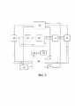
На Фиг.4 изображена блок-схема устройства для дезактивации в целом и ее основные рабочие элементы.Figure 4 shows a block diagram of the device for decontamination as a whole and its main operating elements.
Осуществление изобретенияImplementation of the invention
Согласно широкому подходу к реализации устройств для плазменной дезактивации, изложенному в описании и в формуле предлагаемого изобретения, возможно множество различных вариантов такого устройства. Без нарушения общности заявляемого технического решения, наилучший вариант плазменной ячейки для дезактивации (на Фиг.1 представлен вид сверху со стороны подключения внешних магистралей, на Фиг.2 представлен поперечный разрез по линии А-А на Фиг.1) состоит из металлического корпуса (1); диэлектрической крышки (2); сменного анода (3); при этом эластичная кольцевая прокладка (4) установлена по периметру металлического корпуса (1) и обеспечивает герметичное прилегание корпуса ячейки к дезактивируемой поверхности (5).According to the broad approach to the implementation of devices for plasma decontamination, set forth in the description and in the claims of the present invention, many different variants of such a device are possible. Without violating the generality of the proposed technical solution, the best version of the plasma cell for decontamination (figure 1 shows a top view from the side of connecting external lines, figure 2 shows a cross section along the line A-A in figure 1) consists of a metal case (1 ); dielectric cover (2); replaceable anode (3); at the same time, an elastic annular gasket (4) is installed along the perimeter of the metal case (1) and ensures a tight fit of the cell body to the decontaminated surface (5).
Металлический корпус (1) выполнен в виде кольца. Как показано на Фиг.2, со стороны обрабатываемой поверхности (5) корпус (1) имеет круговой паз (6) для установки эластичной кольцевой прокладкой (4). Металлический корпус (1) также имеет внутреннюю кольцевую полость (7) для подачи рабочего газа по всему периметру корпуса (1), два патрубка (8), соединенные кольцевой полостью (7) и с системой подачи рабочего газа, а также несколько равноотстоящих друг от друга отверстий (9) для равномерной подачи газа в разрядный промежуток (10). Такая система подачи рабочего инертного газа обеспечивает подачу рабочего газа от периферии ячейки к ее центру, за счет этого распыленные радионуклиды с дезактивируемой поверхности (5) не попадают на внутренние поверхности ячейки, а направляются на поверхность и во внутреннюю полость сменного анода (3). Это также препятствует попаданию атмосферного воздуха в разрядный промежуток (10) при условии подачи рабочего газа во внутреннюю кольцевую полость (7) под давлением, немного выше атмосферного.The metal case (1) is made in the form of a ring. As shown in Fig. 2, on the side of the machined surface (5), the body (1) has a circular groove (6) for mounting with an elastic ring gasket (4). The metal body (1) also has an internal annular cavity (7) for supplying working gas around the entire perimeter of the body (1), two nozzles (8) connected by the annular cavity (7) and with the working gas supply system, as well as several equally spaced other holes (9) for uniform gas supply to the discharge gap (10). Such a working inert gas supply system ensures the supply of working gas from the periphery of the cell to its center, due to this, the sputtered radionuclides from the decontaminated surface (5) do not fall on the inner surfaces of the cell, but are directed to the surface and into the internal cavity of the replaceable anode (3). This also prevents atmospheric air from entering the discharge gap (10), provided that the working gas is supplied to the inner annular cavity (7) at a pressure slightly higher than atmospheric pressure.
Дополнительно металлический корпус (1) имеет три выступа (11) с установленными на них приводами линейного перемещения - актуаторами (12) на базе шаговых двигателей, которые позволяют регулировать зазор между анодом (3) и катодом - дезактивируемой поверхностью (5). Выступы (11) и актуаторы (12) распложены под углом 120 градусов друг относительно друга по периметру металлического корпуса (1). На Фиг.2 в продольном разрезе устройства показан один выступов (11) и один из актуаторов (12). Актуаторы управляются независимо друг от друга через микропроцессорную систему и обеспечивают установку зазора разрядного промежутка (10) по всей площади анода (3) и без короткого замыкания с катодной поверхностью (5). Металлический корпус (1) соединен через показанный условно узел крепления (13) с трехкоординатным манипулятором, который обеспечивает возможность программируемого перемещения устройства по дезактивируемой поверхности (5). Additionally, the metal case (1) has three protrusions (11) with linear displacement drives installed on them - actuators (12) based on stepper motors, which allow you to adjust the gap between the anode (3) and the cathode - the decontaminated surface (5). The protrusions (11) and actuators (12) are located at an angle of 120 degrees relative to each other along the perimeter of the metal case (1). Figure 2 in longitudinal section of the device shows one of the protrusions (11) and one of the actuators (12). The actuators are controlled independently from each other through a microprocessor system and provide the setting of the discharge gap (10) over the entire area of the anode (3) and without a short circuit with the cathode surface (5). The metal case (1) is connected through the conventionally shown mount (13) with a three-coordinate manipulator, which provides the possibility of programmable movement of the device along the decontaminated surface (5).
Изолирующая сменный анод (3) от катодной поверхности (5) диэлектрическая крышка (2) имеет цилиндрическую форму и соосно крепится к металлическому корпусу (1) болтами (болты не показаны на фигурах чертежей для простоты). Для герметизации соединения корпуса (1) и диэлектрической крышки (2) устанавливается кольцевая (например, из витона или фторопласта) прокладка (14).The dielectric cover (2) isolating the replaceable anode (3) from the cathode surface (5) has a cylindrical shape and is coaxially attached to the metal case (1) by bolts (the bolts are not shown in the figures of the drawings for simplicity). To seal the connection between the body (1) and the dielectric cover (2), an annular (for example, made of Viton or PTFE) gasket (14) is installed.
Квадратный анод (3) изготовлен из металла с высокой теплопроводностью, например меди или алюминия, и представляет собой коробчатую двухэтажную конструкцию. Первый этаж является внутренней полостью для прокачки охлаждающей жидкости или газа над всей поверхностью анода (3), обращенной к катоду (5). К этой полости присоединены с помощью сварки или пайки входной (15) и выходной (16) патрубки для подачи и отвода охлаждающей среды. На патрубках (15) и (16) имеется резьба, патрубки проходят через отверстия в крышке (2), с помощью накидных гаек (17) и (18) сменный анод соединяется с крышкой (2). Это соединение герметизируется с помощью эластичных прокладок (19) и (20). Принудительное охлаждение анода необходимо для поддержания достаточно низкой температуры анода в процессе плазменного разряда, т.к. все распыленные радионуклиды должны быть задержаны и сконденсированы внутри сменного анода (3) во избежание поступления их в систему откачки рабочего инертного газа.The square anode (3) is made of a metal with high thermal conductivity, such as copper or aluminum, and is a box-shaped two-story structure. The first floor is an internal cavity for pumping coolant or gas over the entire surface of the anode (3) facing the cathode (5). Inlet (15) and outlet (16) branch pipes are attached to this cavity by means of welding or soldering for supply and removal of the cooling medium. On the branch pipes (15) and (16) there is a thread, the branch pipes pass through the holes in the cover (2), with the help of union nuts (17) and (18) the replaceable anode is connected to the cover (2). This connection is sealed with elastic seals (19) and (20). Forced cooling of the anode is necessary to maintain a sufficiently low anode temperature during the plasma discharge, since all sputtered radionuclides must be retained and condensed inside the replaceable anode (3) to prevent them from entering the working inert gas pumping system.
Второй этаж сменного анода (3) образует вторая внутренняя полость над первой полостью для откачки рабочего инертного газа и осаждения распыленных атомов внутри полости. Откачка рабочего газа происходит из разрядного промежутка (10) между анодом (3) и катодом (5) через трубку с отверстием (21), соединенную с помощью сварки или пайки в центре нижней поверхности анода (3), а также со второй внутренней полостью анода (3). Сверху ко второй внутренней полость анода (3) присоединен с помощью сварки или пайки патрубок откачки рабочего газа (22), на котором имеется резьба. Патрубок откачки (22) также проходит через отверстия в крышке (2). С помощью накидной гайки (23) сменный анод дополнительно соединяется с крышкой (2) и герметизируется с помощью эластичной прокладки (24). Дополнительно, во второй внутренней полости анода (3) установлен плоский вкладыш (25) во всю высоту полости, имеющий спиральную форму. Это обеспечивает удлинение пути откачиваемого газа, необходимое для более полного улавливания радионуклидов внутри сменного анода (3) из потока откачиваемого рабочего газа.The second floor of the replaceable anode (3) forms a second internal cavity above the first cavity for pumping out the working inert gas and depositing sputtered atoms inside the cavity. The working gas is pumped out from the discharge gap (10) between the anode (3) and the cathode (5) through a tube with a hole (21) connected by welding or soldering in the center of the lower surface of the anode (3), as well as to the second internal cavity of the anode (3). From above, to the second internal cavity of the anode (3) is connected by welding or soldering the branch pipe for pumping out the working gas (22), which has a thread. The evacuation pipe (22) also passes through the holes in the cover (2). With the help of a union nut (23), the replaceable anode is additionally connected to the cover (2) and sealed with an elastic gasket (24). Additionally, in the second internal cavity of the anode (3) there is a flat insert (25) in the entire height of the cavity, having a spiral shape. This provides an extension of the path of the evacuated gas, which is necessary for a more complete capture of radionuclides inside the replaceable anode (3) from the stream of evacuated working gas.
Для дезактивации вогнутой или выпуклой поверхности предназначен вариант плазменной ячейки, изображенный на Фиг.3 (поперечный разрез). В отличие от случая дезактивации плоской поверхности, представленного на Фиг.1,2, катодом (26) является вогнутая проводящая поверхность, например внутренняя поверхность первого контура ядерного реактора или питающих трубопроводов. В этом случае изменяется только форма сменного анода (27), поверхность которого, обращенная к катоду, имеет выпуклую форму, геометрически подобную форме дезактивируемой поверхности (26). Остальные конструктивные элементы плазменной ячейки на Фиг.3 идентичны устройству на Фиг.1 и Фиг.2.To deactivate a concave or convex surface, a variant of the plasma cell shown in Fig. 3 (cross section) is intended. In contrast to the case of decontamination of a flat surface, presented in Fig.1,2, the cathode (26) is a concave conductive surface, such as the inner surface of the primary circuit of a nuclear reactor or supply pipelines. In this case, only the shape of the replaceable anode (27) changes, the surface of which, facing the cathode, has a convex shape, geometrically similar to the shape of the deactivated surface (26). The remaining structural elements of the plasma cell in Fig.3 are identical to the device in Fig.1 and Fig.2.
Фиг.4 иллюстрирует блок-схему устройства для плазменной дезактивации поверхности элементов ядерных энергетических установок, которое включает плазменную ячейку (28), варианты которой изображены на Фиг.1-3, и компьютер (29), управляющий электромагнитным вентилем (30), соединенным через редуктор (31) с баллоном инертного газа (32) и обеспечивающим подачу рабочего газа в разрядный промежуток плазменной ячейки; а также насосом (33), обеспечивающим откачку газа из разрядного промежутка плазменной ячейки. Подача инертного газа осуществляется в замкнутом цикле с помощью циркулятора газа (34). Пунктирными стрелками указано направление циркуляции инертного газа.Figure 4 illustrates a block diagram of a device for plasma decontamination of the surface of elements of nuclear power plants, which includes a plasma cell (28), variants of which are shown in Figures 1-3, and a computer (29) that controls the electromagnetic valve (30) connected via a reducer (31) with an inert gas cylinder (32) that supplies the working gas to the discharge gap of the plasma cell; as well as a pump (33), which pumps out gas from the discharge gap of the plasma cell. The supply of inert gas is carried out in a closed cycle using a gas circulator (34). Dashed arrows indicate the direction of circulation of the inert gas.
Управляемый компьютером (29) источник питания (35), отрицательным полюсом подключенный к дезактивируемому элементу конструкции ядерного реактора, а положительным полюсом подключенный к сменному аноду (3) плазменной ячейки через ключ (36), обеспечивает включение/выключение блока питания для зажигания и поддержания укороченного плазменного разряда высокого давления (до 1 атм) между анодом (3) и обрабатываемой поверхностью (5) при напряжении в диапазоне от 200 до 1000 Вольт и плотности тока в диапазоне от 0,1 до 1 А/см2. Кроме того, к компьютеру (29) подключены 3 актуатора (12) для управления зазором между дезактивируемой поверхностью (5) и анодом (3), а также набор датчиков (37), смонтированных на плазменной ячейке (28) и измеряющих напряжение на разрядном промежутке (10), силу тока разряда, давление газа, температуру в различных точках ячейки и уровень радиации.A computer-controlled (29) power supply (35), with a negative pole connected to a deactivated structural element of a nuclear reactor, and a positive pole connected to a replaceable anode (3) of the plasma cell through a key (36), provides switching on / off of the power supply for ignition and maintaining a shortened high-pressure plasma discharge (up to 1 atm) between the anode (3) and the treated surface (5) at a voltage in the range from 200 to 1000 Volts and a current density in the range from 0.1 to 1 A/cm2 . In addition, 3 actuators (12) are connected to the computer (29) to control the gap between the deactivated surface (5) and the anode (3), as well as a set of sensors (37) mounted on the plasma cell (28) and measuring the voltage across the discharge gap (10), discharge current, gas pressure, temperature at various points in the cell and radiation level.
Система принудительного водяного или газового охлаждения обеспечивает отвод теплового потока из плазмы на сменный анод плазменной ячейки (28) и включает магистрали для подвода и отвода охлаждающей среды и циркуляционный насос с радиатором (38) и измерителем температуры, также управляемый компьютером (29).The forced water or gas cooling system removes the heat flux from the plasma to the replaceable anode of the plasma cell (28) and includes lines for supplying and removing the cooling medium and a circulation pump with a radiator (38) and a temperature meter, also controlled by a computer (29).
Устройство для плазменной дезактивации поверхности элементов ядерных энергетических установок работает следующим образом. Плазменную ячейку располагают на участке обрабатываемой поверхности (5) таким образом, что эластичная кольцевая прокладка (4), установленная по периметру металлического корпуса (1) устройства, плотно прилегает к дезактивируемой поверхности (5) и обеспечивает герметизацию разрядного промежутка (10). Посредством трех актуаторов (12) обеспечивается установка расстояния между сменным анодом (3) и дезактивируемой поверхностью (катодом) (5), проверяется отсутствие короткого замыкания между анодом и катодом. Затем включается насос (26) для откачки атмосферного воздуха из разрядного промежутка (10) до давления 103-104 Па, при этом ячейка дополнительно прижимается атмосферным давлением к дезактивируемой поверхности (5). После достижения заданного давления через отверстия (9) в металлическом корпусе (1) плазменной ячейки в разрядный промежуток (10) подается инертный газ (например, аргон) из баллона (32) при давлении 1.0-1.1 атм. посредством редуктора (31) и электромагнитного вентиля (30). Далее источником питания (35) через ключ (36) подается напряжение 600-1000В на разрядный промежуток, заполненный инертным газом, для зажигания разряда между анодом (3) и дезактивируемой поверхностью (5). Положительные ионы инертного газа, источником которых является зажигаемый разряд, ускоряются в электрическом поле катодного слоя и бомбардируют дезактивируемую поверхность (5) с энергией, необходимой для распыления атомов с этой поверхности. Распыленные атомы подхватываются потоком инертного газа от периметра анода (3) к отверстию в его центре и в режиме массопереноса осаждаются на поверхности, а также внутри верхней внутренней полости сменного анода (3). Процесс распыления атомов с дезактивируемой поверхности (5) и их осаждение на поверхности анода (3) осуществляют в условиях замкнутой рециркуляции инертного газа. Оптимальное время дезактивации при одном положении плазменной ячейки, расстояние между анодом (3) и дезактивируемой поверхностью (5), давление инертного газа, напряжение и ток разряда определяют экспериментально и задают программно с помощью компьютера (29). После того, как будет закончен процесс дезактивации выбранного участка поверхности (5), компьютер (29) отключает источник питания (35), прекращает подачу инертного газа в разрядный промежуток (10), и плазменная ячейка (28) перемещается по дезактивируемый поверхности на соседний участок посредством трехкоординатного манипулятора. Далее процесс повторяется, и таким образом за счет последовательных перемещений плазменной ячейки достигается дезактивация заданной области поверхности ядерного реактора.A device for plasma decontamination of the surface of elements of nuclear power plants operates as follows. The plasma cell is placed on the area of the treated surface (5) in such a way that the elastic ring gasket (4) installed along the perimeter of the metal case (1) of the device fits snugly against the decontaminated surface (5) and seals the discharge gap (10). By means of three actuators (12), the distance between the replaceable anode (3) and the deactivated surface (cathode) (5) is set, and the absence of a short circuit between the anode and cathode is checked. Then the pump (26) is turned on to pump out atmospheric air from the discharge gap (10) to a pressure of 103 -104 Pa, while the cell is additionally pressed by atmospheric pressure to the decontaminated surface (5). After reaching the predetermined pressure through the holes (9) in the metal case (1) of the plasma cell, an inert gas (for example, argon) is supplied to the discharge gap (10) from a cylinder (32) at a pressure of 1.0-1.1 atm. by means of a reducer (31) and a solenoid valve (30). Next, the power source (35) through the key (36) supplies a voltage of 600-1000V to the discharge gap filled with an inert gas to ignite the discharge between the anode (3) and the deactivated surface (5). Positive ions of an inert gas, the source of which is an ignited discharge, are accelerated in the electric field of the cathode layer and bombard the deactivated surface (5) with the energy necessary to sputter atoms from this surface. The sputtered atoms are picked up by the inert gas flow from the perimeter of the anode (3) to the hole in its center and are deposited on the surface in the mass transfer mode, as well as inside the upper internal cavity of the replaceable anode (3). The process of sputtering atoms from the decontaminated surface (5) and their deposition on the surface of the anode (3) is carried out under conditions of closed inert gas recirculation. The optimal deactivation time at one position of the plasma cell, the distance between the anode (3) and the deactivated surface (5), inert gas pressure, discharge voltage and current are determined experimentally and set programmatically using a computer (29). After the process of decontamination of the selected surface area (5) is completed, the computer (29) turns off the power source (35), stops the supply of inert gas to the discharge gap (10), and the plasma cell (28) moves along the deactivated surface to the neighboring area with a 3D manipulator. Further, the process is repeated, and thus, due to successive displacements of the plasma cell, deactivation of a given area of the nuclear reactor surface is achieved.
Примером реализации заявленного устройства является вариант дезактивации элементов облученной графитовой кладки ядерного реактора, например реактора типа РБМК. Известно, что основным дозообразующим элементом облученного реакторного графита является изотоп14С, сконцентрированный, главным образом, на поверхности и в приповерхностных микронных слоях элементов графитовой кладки [1-4]. Плазменную ячейку располагают на участке плоской боковой поверхности элемента графитовой кладки реактора РБМК таким образом, что эластичная кольцевая прокладка, установленная по периметру металлического корпуса ячейки, плотно прилегает к дезактивируемой поверхности и обеспечивает герметизацию разрядного промежутка. Посредством актуаторов устанавливается расстояние в 1 мм между сменным анодом и дезактивируемой поверхностью облученного реакторного графита. Затем включается форвакуумный насос для откачки атмосферного воздуха из разрядного промежутка до давления 103-104 Па. При достижении заданного давления в разрядном промежутке по периметру плазменной ячейки подается аргон при избыточном давлении 0,1-0,2 атм, а в разрядном промежутке давление газа порядка 104Па. Далее с помощью источника питания через ключ подается напряжение 600 В на разрядный промежуток, заполненный агоном, и зажигается разряд между сменным анодом и дезактивируемой поверхностью графита. Положительные ионы аргона приобретают в катодном слое плазмы энергию до 500 эВ и распыляют атомы углерода, включая и атомы изотопа14С, с поверхности облученного реакторного графита. Распыленные атомы изотопа14С в режиме массопереноса осаждаются на поверхности сменного анода. Коэффициент распыления поверхности графита ионами аргона с энергией 500 эВ составляет порядка 0.1 [5]. При плотности тока ионовj= 1 А/см2, согласно выражениюAn example of the implementation of the claimed device is a variant of decontamination of the elements of the irradiated graphite masonry of a nuclear reactor, for example, a reactor of the RBMK type. It is known that the main dose-forming element of irradiated reactor graphite is the 14C isotope, which is concentrated mainlyon the surface and in near-surface micron layers of graphite stack elements [1–4]. The plasma cell is placed on the area of the flat side surface of the graphite stack element of the RBMK reactor in such a way that the elastic annular gasket installed along the perimeter of the metal case of the cell fits snugly against the decontaminated surface and ensures the sealing of the discharge gap. By means of actuators, a distance of 1 mm is set between the replaceable anode and the decontaminated surface of the irradiated reactor graphite. Then the fore-vacuum pump is turned on for pumping out atmospheric air from the discharge gap to a pressure of 103 -104 Pa. When the specified pressure is reached in the discharge gap along the perimeter of the plasma cell, argon is supplied at an excess pressure of 0.1-0.2 atm, and in the discharge gap the gas pressure is about 104 Pa. Then, with the help of a power source, a voltage of 600 V is applied through the key to the discharge gap filled with agon, and a discharge is ignited between the replaceable anode and the graphite surface to be deactivated. Positive argon ions acquire energy up to 500 eV in the plasma cathode layer and sputter carbon atoms, including atoms of the14C isotope, from the surface of irradiated reactor graphite. The sputtered atoms of the isotope14 C in the mass transfer mode are deposited on the surface of a replaceable anode. The sputtering coefficient of the graphite surface by argon ions with an energy of 500 eV is about 0.1 [5]. At an ion current densityj =1 A/cm2, according to the expression
Vp=K⋅j⋅Mc/e⋅Na⋅ρ (1)Vp=K⋅j⋅Mc/e⋅Na⋅ρ (1)
скорость распыления углерода ионами аргона составит 0.75⋅10-5см/с, а для распыления слоя графита толщиной 1 мкм потребуется время ~ 13 с.the sputtering rate of carbon by argon ions will be 0.75⋅10-5 cm/s, and sputtering of a
В выражении (1)e – заряд электрона, Кл;ρ – плотность материала, г/см3;j – плотность тока ионов, А/см2;Мс– масса атомов материала (углерода), г/моль;Na– число Авогадро, моль-1;Vp = h/t– скорость распыления;h – толщина стравливаемого слоя материала, см;t –время распыления, с.In expression (1)e is the electron charge, C;p – material density, g/cm3;j is the ion current density, A/cm2;Mwithis the mass of atoms of the material (carbon), g/mol;Na– Avogadro number, mole-one;Vp= h/t– spraying speed;h is the thickness of the etched material layer, cm;t –spray time, s.
При площади поверхности сменного анода ~ 100 см2 дезактивация на глубину 1 мкм элемента кладки размерами 25x25x60 см и площадью поверхности 7250 см2составит около 17 минут. Процесс дезактивации всей поверхности графитовой кладки реактора производится последовательно от одного элемента кладки к другому посредством перемещения плазменной ячейки трехкоординатным манипулятором по дезактивируемой поверхности.With a replaceable anode surface areaof ~ 100 cm2, decontamination to a depth of 1 µm of a masonry element with dimensions of 25x25x60 cm and a surface areaof 7250 cm2 will be about 17 minutes. The process of decontamination of the entire surface of the graphite stack of the reactor is carried out sequentially from one element of the stack to another by moving the plasma cell with a three-axis manipulator along the decontaminated surface.
Вторым примером реализации устройства является дезактивация внутренних поверхностей трубопроводов первого контура реактора. Внутренний диаметр циркониевых трубопроводов первого контура реактора ВВЭР-1000 составляет 85 мм. Последовательность действий при дезактивации внутренней поверхности трубопроводов первого контура реактора аналогична последовательности действий при дезактивации элементов облученной графитовой кладки ядерного реактора из первого примера. С помощью актуаторов устанавливается расстояние в 1 мм между анодом и дезактивируемой поверхностью (катодом). Положительные ионы аргона, источником которых является зажигаемый разряд, ускоряются в электрическом поле катодного слоя плазмы, приобретают энергию до 500 эВ и распыляют поверхностные загрязнения на внутренней поверхности трубопровода. Распыленные атомы загрязнения с внутренней поверхности трубопровода в режиме массопереноса осаждаются на поверхности и внутри сменного анода, который после заполнения радиоактивным осадком заменяется и захоранивается. Коэффициент распыления поверхности циркония ионами аргона с энергией 500 эВ величину 0.6 [5]. При плотности тока ионовj= 1 А/см2, согласно выражению (1), скорость распыления радиоактивных загрязнений ионами аргона составит 0.88⋅10-4см/с, а для распыления слоя радиоактивных загрязнений толщиной 1 мкм потребуется время ~ 1.13 с. При площади поверхности анода ~100 см2 дезактивация на глубину 1 мкм внутренней поверхности трубопровода диаметром 85 мм и длиной в 1 м составит около 5 минут. Процесс дезактивации всей внутренней поверхности трубопроводов первого контура производится последовательно от одного участка трубопровода к другому посредством перемещения плазменной ячейки трехкоординатным манипулятором по дезактивируемой поверхности.The second example of the implementation of the device is the decontamination of the internal surfaces of the pipelines of the primary circuit of the reactor. The inner diameter of the zirconium pipelines in the primary circuit of the VVER-1000 reactor is 85 mm. The sequence of actions for decontamination of the inner surface of the pipelines of the primary circuit of the reactor is similar to the sequence of actions for the decontamination of elements of the irradiated graphite stack of a nuclear reactor from the first example. Using actuators, a distance of 1 mm is set between the anode and the decontaminated surface (cathode). Positive argon ions, the source of which is an ignited discharge, are accelerated in the electric field of the plasma cathode layer, acquire energy up to 500 eV, and spray surface contaminants on the inner surface of the pipeline. Sputtered contamination atoms from the inner surface of the pipeline in the mass transfer mode are deposited on the surface and inside the replaceable anode, which, after filling with radioactive residue, is replaced and buried. The coefficient of sputtering of the zirconium surface by argon ions with an energy of 500 eV is 0.6 [5]. At an ion current densityj =1 A/cm2, according to expression (1), the rate of sputtering of radioactive contamination by argon ions will be 0.88⋅10-4 cm/s, and sputtering of a layer of
Промышленная применимостьIndustrial Applicability
Устройство для дезактивации металлических конструкционных элементов ядерных энергетических установок и для поверхностной дезактивации облученной графитовой кладки построено на общеизвестных принципах физики плазмы и электроники, основные конструктивные элементы устройства изготавливаются из распространенных в практике материалов (металлы, керамика и пр.) с помощью традиционных в машиностроении технологий (фрезерование, сверление, токарная обработка, сварка и т.п.). Также используемые в устройстве комплектующие серийно выпускаются промышленностью, все это в совокупности обеспечивает практическую осуществимость заявленного изобретения.The device for the decontamination of metal structural elements of nuclear power plants and for the surface decontamination of irradiated graphite masonry is built on the well-known principles of plasma physics and electronics, the main structural elements of the device are made from materials common in practice (metals, ceramics, etc.) using traditional engineering technologies ( milling, drilling, turning, welding, etc.). The components also used in the device are mass-produced by the industry, all this together ensures the practical feasibility of the claimed invention.
ИСТОЧНИКИ ИНФОРМАЦИИINFORMATION SOURCES
1. LaBrier, Daniel; Dunzik-Gougar, Mary Lou, «Characterization of 14C in neutron irradiated NBG-25 nuclear graphite», Journal of Nuclear Materials, Volume 448, Issue 1-3, p. 113-120, 2014; https://www.sciencedirect.com/science/article/pii/S0022311514000531?via%3Dihub1. LaBrier, Daniel; Dunzik-Gougar, Mary Lou, "Characterization of 14C in neutron irradiated NBG-25 nuclear graphite", Journal of Nuclear Materials, Volume 448, Issue 1-3, p. 113-120, 2014; https://www.sciencedirect.com/science/article/pii/S0022311514000531?via%3Dihub
2. Dunzik-Gougar, Mary Lou; Smith, Tara E. «Removal of carbon-14 from irradiated graphite Journal of Nuclear Materials», Volume 451, Issue 1-3, p. 328-335, 2014.2. Dunzik-Gougar, Mary Lou; Smith, Tara E. "Removal of carbon-14 from irradiated graphite Journal of Nuclear Materials", Volume 451, Issue 1-3, p. 328-335, 2014.
3. А.О. Павлюк, С.Г. Котляревский, Е.В. Беспала, Ю.Р. Беспала «Перспективы применения исследовательского реактора типа ИРТ-Т для решения задач в рамках проблемы графитовых радиоактивных отходов», Известия ВУЗОВ, Ядерная энергетика № 1, 2018, стр. 87-98, DOI 10.26583/npe.2018.1.09.3. A.O. Pavlyuk, S.G. Kotlyarevsky, E.V. Bespala, Yu.R. Bespal "Prospects for the use of a research reactor of the IRT-T type for solving problems in the framework of the problem of graphite radioactive waste", Izvestiya VUZOV, Nuclear Energy No. 1, 2018, pp. 87-98, DOI 10.26583/npe.2018.1.09.
4. Vulpius D., Baginski K., Fischer C., Thomauske B. «Location and chemical bond of radionuclides in neutron irradiated nuclear graphite». Journal of Nuclear Materials. 2013, v.438, pp. 163-177.4. Vulpius D., Baginski K., Fischer C., Thomauske B. "Location and chemical bond of radionuclides in neutron irradiated nuclear graphite". Journal of Nuclear Materials. 2013, v.438, pp. 163-177.
5. «Проблемы прикладной физики. Распыление твердых тел ионной бомбардировкой», том 1 под редакцией Р. Бериша, Издательство "Мир", Москва 1984, с.335.5. “Problems of Applied Physics. Sputtering of Solids by Ion Bombardment,
Claims (8)
Translated fromRussianPriority Applications (1)
| Application Number | Priority Date | Filing Date | Title |
|---|---|---|---|
| RU2021113323ARU2771172C1 (en) | 2021-05-11 | 2021-05-11 | Apparatus for plasma decontamination of structural elements of a nuclear reactor |
Applications Claiming Priority (1)
| Application Number | Priority Date | Filing Date | Title |
|---|---|---|---|
| RU2021113323ARU2771172C1 (en) | 2021-05-11 | 2021-05-11 | Apparatus for plasma decontamination of structural elements of a nuclear reactor |
Publications (1)
| Publication Number | Publication Date |
|---|---|
| RU2771172C1true RU2771172C1 (en) | 2022-04-28 |
Family
ID=81458843
Family Applications (1)
| Application Number | Title | Priority Date | Filing Date |
|---|---|---|---|
| RU2021113323ARU2771172C1 (en) | 2021-05-11 | 2021-05-11 | Apparatus for plasma decontamination of structural elements of a nuclear reactor |
Country Status (1)
| Country | Link |
|---|---|
| RU (1) | RU2771172C1 (en) |
Cited By (1)
| Publication number | Priority date | Publication date | Assignee | Title |
|---|---|---|---|---|
| RU2833795C1 (en)* | 2024-07-16 | 2025-01-28 | Федеральное государственное бюджетное учреждение науки Институт ядерной физики им. Г.И. Будкера Сибирского отделения Российской академии наук | Arc plasma generator |
Citations (3)
| Publication number | Priority date | Publication date | Assignee | Title |
|---|---|---|---|---|
| JP2562164B2 (en)* | 1987-01-05 | 1996-12-11 | コミツサリア タ レネルジー アトミーク | Decontamination method and device for metal surface |
| RU2374046C2 (en)* | 2007-07-27 | 2009-11-27 | Евгений Степанович Сенокосов | Method for surface cleaning of large-size metal items with arc discharge and device for its realisation |
| RU2711292C1 (en)* | 2018-11-21 | 2020-01-16 | Акционерное Общество "Российский Концерн По Производству Электрической И Тепловой Энергии На Атомных Станциях" (Ао "Концерн Росэнергоатом") | Nuclear reactor design decontamination method |
- 2021
- 2021-05-11RURU2021113323Apatent/RU2771172C1/enactive
Patent Citations (3)
| Publication number | Priority date | Publication date | Assignee | Title |
|---|---|---|---|---|
| JP2562164B2 (en)* | 1987-01-05 | 1996-12-11 | コミツサリア タ レネルジー アトミーク | Decontamination method and device for metal surface |
| RU2374046C2 (en)* | 2007-07-27 | 2009-11-27 | Евгений Степанович Сенокосов | Method for surface cleaning of large-size metal items with arc discharge and device for its realisation |
| RU2711292C1 (en)* | 2018-11-21 | 2020-01-16 | Акционерное Общество "Российский Концерн По Производству Электрической И Тепловой Энергии На Атомных Станциях" (Ао "Концерн Росэнергоатом") | Nuclear reactor design decontamination method |
Non-Patent Citations (1)
| Title |
|---|
| Петровская А.С. и др. "ИННОВАЦИОННЫЙ МЕТОД ПЛАЗМЕННОЙ ДЕЗАКТИВАЦИИ КОНСТРУКЦИЙ ЯДЕРНЫХ ЭНЕРГЕТИЧЕСКИХ УСТАНОВОК И ОБЛУЧЕННОГО РЕАКТОРНОГО ГРАФИТА", ЯДЕРНО-РЕАКТОРНЫЕ КОНСТАНТЫ, выпуск 4, 2018.* |
Cited By (1)
| Publication number | Priority date | Publication date | Assignee | Title |
|---|---|---|---|---|
| RU2833795C1 (en)* | 2024-07-16 | 2025-01-28 | Федеральное государственное бюджетное учреждение науки Институт ядерной физики им. Г.И. Будкера Сибирского отделения Российской академии наук | Arc plasma generator |
Similar Documents
| Publication | Publication Date | Title |
|---|---|---|
| US5378898A (en) | Electron beam system | |
| US5681434A (en) | Method and apparatus for ionizing all the elements in a complex substance such as radioactive waste and separating some of the elements from the other elements | |
| US5868909A (en) | Method and apparatus for improving the energy efficiency for separating the elements in a complex substance such as radioactive waste with a large volume plasma processor | |
| Bricault et al. | Rare isotope beams at ISAC—target & ion source systems | |
| Peng et al. | Fusion nuclear science facility (FNSF) before upgrade to component test facility (CTF) | |
| RU2771172C1 (en) | Apparatus for plasma decontamination of structural elements of a nuclear reactor | |
| KR20240046484A (en) | particle generation device | |
| CN1045637C (en) | Plasma immersion ion implantation apparatus for material surface modifying | |
| RU2686399C1 (en) | Device and method for coating long products | |
| Singh et al. | R&D status of the Indian test facility for ITER diagnostic neutral beam characterization | |
| RU2496913C2 (en) | Unit for ion-ray and plasma processing | |
| WO2023033993A1 (en) | High-energy plasma generator with permanent magnet divertor | |
| CN112655056A (en) | Method for decontaminating structural elements of a nuclear reactor | |
| EA009514B1 (en) | Method of ion treatment of dielectric surface and device for implementing thereof | |
| EP4432306A1 (en) | Plasma curtain generator in atmospheric pressure state using high voltage and magnetic force and low-vacuum incineration facility for low- and intermediate-level radioactive waste treatment using same | |
| Mazul et al. | First wall components | |
| Alton et al. | Design features of a high‐intensity, cesium‐sputter/plasma‐sputter negative ion sourcea | |
| Petrovskaya et al. | Surface deactivation of the nuclear power plants constructions by a new plasma method | |
| EA040021B1 (en) | METHOD FOR DEACTIVATION OF NUCLEAR REACTOR STRUCTURAL ELEMENT | |
| Aaron et al. | The Final Design of the Plasma–Material Interaction Chamber for the Material Plasma Exposure eXperiment | |
| Engelmann et al. | Plasma-wall interaction in NET | |
| Singh et al. | R&D Status of Indian Test Facility for ITER DNB Characterization | |
| Bricault et al. | The production target at ISAC | |
| Calderon et al. | Mechanical design for TMX injector system | |
| CN118302827A (en) | Plasma curtain generator in atmospheric pressure state using high voltage and magnetic force and low vacuum incineration facility for treating low horizontal radioactive waste using the same |