RU2765998C1 - Sweeper - Google Patents
SweeperDownload PDFInfo
- Publication number
- RU2765998C1 RU2765998C1RU2021123464ARU2021123464ARU2765998C1RU 2765998 C1RU2765998 C1RU 2765998C1RU 2021123464 ARU2021123464 ARU 2021123464ARU 2021123464 ARU2021123464 ARU 2021123464ARU 2765998 C1RU2765998 C1RU 2765998C1
- Authority
- RU
- Russia
- Prior art keywords
- fixed
- conveyor belt
- carriage
- brush
- drive
- Prior art date
Links
- 241001417527PempheridaeSpecies0.000titleclaimsabstractdescription22
- 239000010813municipal solid wasteSubstances0.000claimsabstractdescription41
- 239000000428dustSubstances0.000claimsabstractdescription26
- XLYOFNOQVPJJNP-UHFFFAOYSA-NwaterSubstancesOXLYOFNOQVPJJNP-UHFFFAOYSA-N0.000claimsabstractdescription8
- 230000001174ascending effectEffects0.000claimsabstractdescription7
- 230000000284resting effectEffects0.000claimsabstractdescription4
- 239000002699waste materialSubstances0.000claimsdescription12
- 230000015572biosynthetic processEffects0.000claimsdescription2
- 230000013011matingEffects0.000claims1
- 238000004140cleaningMethods0.000abstractdescription6
- 238000000034methodMethods0.000abstractdescription6
- 238000010408sweepingMethods0.000abstractdescription6
- 230000000694effectsEffects0.000abstractdescription5
- 238000009825accumulationMethods0.000abstract1
- 238000000576coating methodMethods0.000abstract1
- 239000000126substanceSubstances0.000abstract1
- 239000000463materialSubstances0.000description8
- 230000007613environmental effectEffects0.000description4
- 238000003912environmental pollutionMethods0.000description2
- 238000003306harvestingMethods0.000description2
- 238000009434installationMethods0.000description2
- 239000006096absorbing agentSubstances0.000description1
- 244000309464bullSpecies0.000description1
- 238000013016dampingMethods0.000description1
- 239000002245particleSubstances0.000description1
- 230000035939shockEffects0.000description1
- 238000010407vacuum cleaningMethods0.000description1
Images


Classifications
- E—FIXED CONSTRUCTIONS
- E01—CONSTRUCTION OF ROADS, RAILWAYS, OR BRIDGES
- E01H—STREET CLEANING; CLEANING OF PERMANENT WAYS; CLEANING BEACHES; DISPERSING OR PREVENTING FOG IN GENERAL CLEANING STREET OR RAILWAY FURNITURE OR TUNNEL WALLS
- E01H1/00—Removing undesirable matter from roads or like surfaces, with or without moistening of the surface
- E01H1/02—Brushing apparatus, e.g. with auxiliary instruments for mechanically loosening dirt
- E01H1/04—Brushing apparatus, e.g. with auxiliary instruments for mechanically loosening dirt taking- up the sweepings, e.g. for collecting, for loading
- E01H1/042—Brushing apparatus, e.g. with auxiliary instruments for mechanically loosening dirt taking- up the sweepings, e.g. for collecting, for loading the loading means being an endless belt or an auger
- E—FIXED CONSTRUCTIONS
- E01—CONSTRUCTION OF ROADS, RAILWAYS, OR BRIDGES
- E01H—STREET CLEANING; CLEANING OF PERMANENT WAYS; CLEANING BEACHES; DISPERSING OR PREVENTING FOG IN GENERAL CLEANING STREET OR RAILWAY FURNITURE OR TUNNEL WALLS
- E01H1/00—Removing undesirable matter from roads or like surfaces, with or without moistening of the surface
- E01H1/02—Brushing apparatus, e.g. with auxiliary instruments for mechanically loosening dirt
- E01H1/04—Brushing apparatus, e.g. with auxiliary instruments for mechanically loosening dirt taking- up the sweepings, e.g. for collecting, for loading
- E01H1/045—Brushing apparatus, e.g. with auxiliary instruments for mechanically loosening dirt taking- up the sweepings, e.g. for collecting, for loading the loading means being a rotating brush with horizontal axis
- E—FIXED CONSTRUCTIONS
- E01—CONSTRUCTION OF ROADS, RAILWAYS, OR BRIDGES
- E01H—STREET CLEANING; CLEANING OF PERMANENT WAYS; CLEANING BEACHES; DISPERSING OR PREVENTING FOG IN GENERAL CLEANING STREET OR RAILWAY FURNITURE OR TUNNEL WALLS
- E01H1/00—Removing undesirable matter from roads or like surfaces, with or without moistening of the surface
- E01H1/08—Pneumatically dislodging or taking-up undesirable matter or small objects; Drying by heat only or by streams of gas; Cleaning by projecting abrasive particles
- E01H1/0827—Dislodging by suction; Mechanical dislodging-cleaning apparatus with independent or dependent exhaust, e.g. dislodging-sweeping machines with independent suction nozzles ; Mechanical loosening devices working under vacuum
- E01H1/0836—Apparatus dislodging all of the dirt by suction ; Suction nozzles
- E01H1/0845—Apparatus dislodging all of the dirt by suction ; Suction nozzles with mechanical loosening or feeding instruments for the dirt to be sucked- up, e.g. brushes, scrapers
Landscapes
- Engineering & Computer Science (AREA)
- Architecture (AREA)
- Civil Engineering (AREA)
- Structural Engineering (AREA)
- Cleaning Of Streets, Tracks, Or Beaches (AREA)
Abstract
Description
Translated fromRussianИзобретение относится к области коммунального машиностроения, а именно к технике для подметания проезжей части и тротуаров в населенных пунктах.The invention relates to the field of municipal engineering, namely to equipment for sweeping the roadway and sidewalks in populated areas.
При механизированной уборке улиц и тротуаров в населенных наряду с решением задачи по обеспечению полноты и качества работ по содержанию в чистоте этих территорий общественного пользования актуальной проблемой является обеспечение экологической безопасности таких работ для окружающей среды и людей.In the mechanized cleaning of streets and sidewalks in populated areas, along with solving the problem of ensuring the completeness and quality of work to keep these public areas clean, an urgent problem is to ensure the environmental safety of such work for the environment and people.
При рассмотрении технической литературы выявлен ряд технических решений, относящихся к указанной проблематике.When considering the technical literature, a number of technical solutions related to this issue were identified.
Известна подметально-уборочная машина, содержащая транспортное шасси, на раме которого установлен бункер с устройством для боковой гравитационной разгрузки и загрузочным окном в верхней части, приводную цилиндрическую щетку, смонтированный на каркасе конвейер для подачи смета от щетки к загрузочному окну, рычаг, соединенный шарнирами с каркасом и рамой шасси, силовой цилиндр, соединенный шарнирами с рычагом и рамой шасси, серьгу, прикрепленную одним концом шарнирно к каркасу, опорные ролики, закрепленные на нижней части каркаса, дополнительный силовой цилиндр, установленный на шарнирах между рычагом и другим концом серьги, шарнир крепления рычага к каркасу расположен у верхнего конца конвейера, а шарнир крепления рычага к раме шасси расположен на уровне середины конвейера, причем рычаг выполнен с фланцем, опирающимся сверху на раму шасси, а на конце серьги, соединенной с дополнительным силовым цилиндром, выполнен упор, взаимодействующий с каркасом, приводная цилиндрическая щетка смонтирована на раме шасси при помощи шарнирных тяг и амортизатора, причем между каркасом конвейера и шарнирной тягой установлена телескопическая штанга (патент на изобретение RU 2165493, кл. Е01Н 1/04, опубл. 20.04.2001 г., бюл. №11).Known sweeper, comprising a transport chassis, on the frame of which there is a hopper with a device for lateral gravitational unloading and a loading window in the upper part, a drive cylindrical brush, a frame-mounted conveyor for supplying an estimate from the brush to the loading window, a lever connected by hinges with frame and chassis frame, a power cylinder hinged to the lever and the chassis frame, an earring hinged at one end to the frame, support rollers mounted on the bottom of the frame, an additional power cylinder mounted on hinges between the lever and the other end of the earring, the mounting hinge of the lever to the frame is located at the upper end of the conveyor, and the hinge for attaching the lever to the chassis frame is located at the level of the middle of the conveyor, and the lever is made with a flange resting on top of the chassis frame, and at the end of the link connected to the additional power cylinder, a stop is made that interacts with frame, driven cylindrical brush mounti mounted on the chassis frame with the help of articulated rods and a shock absorber, and a telescopic rod is installed between the conveyor frame and the articulated rod (patent for invention RU 2165493, cl. E01H 1/04, publ. 20.04.2001, bul. No. 11).
Недостатками данной машины являются:The disadvantages of this machine are:
возможность попадания в окружающую среду большого количества пыли, поднимаемой с поверхности покрытий улиц и тротуаров в процессе их подметания, в результате чего наносится ощутимый вред экологической безопасности;the possibility of getting into the environment a large amount of dust raised from the surface of the pavements of streets and sidewalks in the process of sweeping them, resulting in significant harm to environmental safety;
недостаточная полнота сбора смета с дорожного покрытия ввиду того, что в результате вращения приводной щетки значительная часть этого смета может спадать с ворса щетки на дорожное покрытие с ее стороны, противоположной направлению движения машины;insufficient completeness of the collection of estimates from the road surface due to the fact that as a result of the rotation of the drive brush, a significant part of this estimate can fall from the pile of the brush onto the road surface from its side opposite to the direction of the machine;
отсутствие возможности для предотвращения потерь собираемого смета при движении приводной щетки и конвейера в результате ветровых и вибрационных воздействий, что может приводить к загрязнению окружающей природной среды.the inability to prevent the loss of the collected estimate during the movement of the drive brush and conveyor as a result of wind and vibration effects, which can lead to environmental pollution.
Известна машина подметально-уборочная прицепная, содержащая раму, лотковые щетки, цилиндрическую щетку, отгрузочный транспортер, механизм навески лотковой щетки, стойку механизма навески, выполненного в виде плоского шарнирно-рычажного параллелограммного механизма с приводом от гидроцилиндра двустороннего действия, установленного между верхним и нижним рычагами, стойка снабжена вертикальной плитой с жестко прикрепленной горизонтальной осью и криволинейными верхним и боковыми пазами с радиусами кривизны, равными расстоянию от оси до геометрических осей пазов, и двумя опорами, причем одна выполнена съемной, в отверстия которых с возможностью поворота помещена ось, имеющая стопорные буртики, нижний рычаг механизма навески выполнен телескопическим, длина которого регулируется за счет выдвижения одной части относительно другой и позволяет изменять угол наклона щетки к подметаемой поверхности, механизм навески шарнирно соединен с рамой горизонтальной цилиндрической пружиной и подвешен к раме с помощью вертикальной цилиндрической пружины и каната, намотанного на барабан, снабженный храповиком со стопором (патент на изобретение RU 2616382, кл. Е01Н 1/04, опубл. 14.04.2017 г., бюл. №11).Known trailed sweeper, comprising a frame, tray brushes, a cylindrical brush, a discharge conveyor, a tray brush attachment mechanism, a rack attachment mechanism made in the form of a flat articulated-lever parallelogram mechanism driven by a double-acting hydraulic cylinder installed between the upper and lower arms , the rack is equipped with a vertical plate with a rigidly attached horizontal axis and curvilinear upper and side grooves with radii of curvature equal to the distance from the axis to the geometric axes of the grooves, and two supports, one of which is removable, in the holes of which an axis with locking collars is placed with the possibility of rotation , the lower arm of the linkage mechanism is made telescopic, the length of which is adjustable by extending one part relative to the other and allows you to change the angle of the brush to the swept surface, the linkage mechanism is pivotally connected to the frame by a horizontal cylindrical spring and suspended from the frame using a vertical cylindrical spring and a rope wound on a drum equipped with a ratchet with a stopper (patent for invention RU 2616382, cl. E01H 1/04, publ. April 14, 2017, bul. No. 11).
Недостатками указанной машины являются:The disadvantages of this machine are:
возможность попадания в окружающую среду большого количества пыли, поднимаемой с поверхности покрытий улиц и тротуаров в процессе их подметания, в результате чего наносится ощутимый вред экологической безопасности;the possibility of getting into the environment a large amount of dust raised from the surface of the pavements of streets and sidewalks in the process of sweeping them, resulting in significant harm to environmental safety;
ограниченные возможности для сбора мусора на поворотных участках улично-дорожной сети, прилегающих к их внешнему радиусу, ввиду большего радиуса поворота подметально-уборочной машины по отношению к радиусу поворота буксирующего ее автомобиля-самосвала;limited opportunities for garbage collection on the turning sections of the road network adjacent to their outer radius, due to the larger turning radius of the sweeper in relation to the turning radius of the dump truck towing it;
отсутствие возможности для предотвращения потерь собираемого мусора при движении щеток, элеватора и отгрузочного транспортера в результате ветровых и вибрационных воздействий, что может приводить к загрязнению окружающей природной среды;the inability to prevent the loss of the collected garbage during the movement of the brushes, the elevator and the discharge conveyor as a result of wind and vibration effects, which can lead to environmental pollution;
сложность управления работой машины в процессе уборки, требующего остановки автомобиля-самосвала, к которому прицепляется машина, для ее включения и выключения.the complexity of controlling the operation of the machine during the harvesting process, which requires stopping the dump truck to which the machine is attached to turn it on and off.
Наиболее близкой к заявляемому изобретению является подметальная машина для проезжей части с несколькими режимами подметания, содержащая по меньшей мере первую и вторую боковые щетки, установленные на машине. Каждая боковая щетка выполнена с возможностью перемещения между убранным положением и выдвинутым положением и имеет двигатель для вращения своей соответствующей боковой щетки в направлении вращения для сметания по меньшей мере части мусора на подметаемой поверхности в область между первой и второй боковыми щетками. Машина содержит также первое всасывающее отверстие на первой стороне машины или рядом с ней и второе всасывающее отверстие на второй стороне машины или рядом с ней. Каждое всасывающее отверстие соединено через соответствующий клапан для воздушного потока с бункером для мусора. При этом каждый клапан для воздушного потока функционирует между по существу открытым положением и по существу закрытым положением. Машина включает вентилятор для создания воздушного потока, проходящего через бункер для мусора и по меньшей мере одно из всасывающих отверстий, когда клапан, связанный с по меньшей мере одним всасывающим отверстием, находится в своем по существу открытом положении. Машина оснащена основной щеткой для перемещения материала, имеющей соответствующий двигатель для вращения. Машина также может содержать первую вспомогательную щетку для перемещения материала, имеющую соответствующий двигатель для вращения первой вспомогательной щетки для перемещения материала вокруг оси вращения в первом направлении вращения для перемещения по меньшей мере части мусора в направлении для захвата первым всасывающим отверстием, когда подметальная машина движется в направлении движения. Также машина может быть оснащена второй вспомогательной щеткой для перемещения материала, имеющей соответствующий двигатель для вращения второй вспомогательной щетки для перемещения материала вокруг оси вращения во втором направлении вращения для перемещения по меньшей мере части мусора в направлении для захвата вторым всасывающим отверстием, когда подметальная машина движется в направлении движения. При этом основную щетку для перемещения материала вращают в выбранном одном из первого направления вращения для перемещения по меньшей мере части мусора к первой вспомогательной щетке для перемещения материала и второго направления вращения для перемещения по меньшей мере части мусора ко второй вспомогательной щетке для перемещения материала (патент на изобретение RU 2721270, кл. Е01Н 1/02, Е01Н 1/04, Е01Н 1/05, Е01Н 1/08, опубл. 18.05.2020 г., бюл. №14).Closest to the claimed invention is a roadway sweeper with multiple sweeping modes, containing at least the first and second side brushes installed on the machine. Each side brush is movable between a retracted position and an extended position and has a motor for rotating its respective side brush in the direction of rotation to sweep at least a portion of the debris on the swept surface into the area between the first and second side brushes. The machine also includes a first suction port on or near the first side of the machine and a second suction port on or near the second side of the machine. Each suction port is connected through a corresponding airflow valve to a waste bin. Each airflow valve operates between a substantially open position and a substantially closed position. The machine includes a fan to create an air flow through the trash bin and at least one of the suction holes when the valve associated with at least one suction hole is in its substantially open position. The machine is equipped with a main brush for moving the material, which has a corresponding motor for rotation. The machine may also include a first material moving auxiliary brush having a corresponding motor for rotating the first material moving auxiliary brush about a rotation axis in a first direction of rotation to move at least a portion of the debris in a direction to be picked up by the first suction opening when the sweeper is moving in the direction movement. Also, the machine may be equipped with a second material moving auxiliary brush having a corresponding motor for rotating the second material moving auxiliary brush about a rotation axis in a second direction of rotation to move at least a portion of the debris in a direction to be picked up by the second suction port when the sweeper is moving in direction of movement. In this case, the main brush for moving the material is rotated in the selected one of the first direction of rotation to move at least part of the debris to the first auxiliary brush to move the material and the second direction of rotation to move at least part of the debris to the second auxiliary brush to move the material (patent for invention RU 2721270, class E01H 1/02, E01H 1/04, E01H 1/05, E01H 1/08, published on May 18, 2020, bull. No. 14).
Недостатками указанной подметальной машины являются:The disadvantages of this sweeper are:
недостаточные возможности по сепарации мусора, поступающего с воздушным потоком в бункер машины, в результате чего часть этого мусора и пыли выбрасывается в окружающую среду, нанося тем самым вред экологической безопасности;insufficient capacity for separating garbage entering the machine bunker with the air flow, as a result of which part of this garbage and dust is released into the environment, thereby harming environmental safety;
отсутствие возможности для сбора мусора, размеры которого превышают размеры всасывающих отверстий механизма перемещения мусора в бункер машины;the inability to collect garbage, the size of which exceeds the size of the suction holes of the mechanism for moving garbage into the bunker of the machine;
сложность прочистки всасывающих отверстий от мусора, размеры которого превышают размеры этих отверстий, что может привести к их закупориванию в процессе работы машины.the difficulty of cleaning the suction holes from debris, the size of which exceeds the size of these holes, which can lead to clogging during operation of the machine.
Задача, решаемая в изобретении, заключается в устранении указанных недостатков путем разработки конструкции подметально-уборочной машины, обеспечивающей сбор мусора и пыли, собираемых с поверхностей покрытий улиц и тротуаров, с минимальными их потерями в процессе эксплуатации машины.The problem solved in the invention is to eliminate these shortcomings by developing a sweeper design that collects debris and dust collected from the surfaces of street and sidewalk pavements, with minimal losses during the operation of the machine.
Технический результат изобретения заключается в снижении негативного воздействия на окружающую среду в процессе уборки проезжей части улиц и тротуаров за счет минимизации потерь мусора и пыли, собираемых с поверхностей покрытий улиц и тротуаров, а также минимизации объемов мусора и пыли, попадающих в окружающую среду в процессе эксплуатации машины.The technical result of the invention is to reduce the negative impact on the environment in the process of cleaning the carriageway of streets and sidewalks by minimizing the loss of debris and dust collected from the surface of the pavements of streets and sidewalks, as well as minimizing the amount of debris and dust entering the environment during operation. cars.
Поставленная задача решается, а технический результат достигается в результате того, что, согласно изобретению, подметально-уборочная машина содержит элемент для сбора мусора, элемент для сбора пыли, приводной элемент и бункер трапецевидной в продольном сечении формы, установленный на грузовой платформе шасси автомобиля, элемент для сбора мусора, выполненный в виде элеватора с установленным в его верхней части сбросным козырьком, включает конвейерную ленту с установленными на ее наружной поверхности перпендикулярно ее продольной оси на равном удалении друг от друга ворсистыми скребками и двумя перфорированными лентами, размещенными параллельно продольной оси конвейерной ленты на удалении от ближайшего ее края, примерно равном 0,35 ее ширины, неподвижно закрепленные между собой с образованием несущего короба две боковины, нижнее и верхнее перекрытия, установленные параллельно соответственно боковым, нижним и верхним поверхностям элеватора и сбросного козырька на расстояниях от них, обеспечивающих свободное движение конвейерной ленты с ворсистыми скребками, верхнюю и две нижние направляющие, размещенные во внутренней полости элеватора и сбросного козырька между восходящим и нисходящим участками конвейерной ленты параллельно верхнему и нижнему перекрытиям и жестко присоединенные к боковинам, две зубчатые каретки, жестко закрепленные на каретном валу на одной линии с каждой из перфорированных лент, подвижно присоединенную к нижнему ребру верхнего перекрытия подпружиненную шторку, выполненную в поперечном разрезе дугообразной формы с радиусом, равным радиусу зубчатой каретки, увеличенному на высоту ворсистого скребка, и снабженную двумя катками, установленными по краям в ее нижней части, три стойки, неподвижно присоединенные в вертикальном положении к задней части грузовой платформы шасси автомобиля на равном удалении друг от друга, винтовой домкрат, подвижно присоединенный своим основанием на шарнире к нижней части стойки, размещенной посередине задней части грузовой платформы шасси автомобиля, а другим концом соединенный с нижним перекрытием посредством пяты, подвижно закрепленной на торце винта, снабженного рукояткой, с возможностью ее вращения вокруг своей оси, и амортизирующую пружину, неподвижно закрепленную на пяте, три петли, присоединенные к верхней части каждой из стоек и к нижнему перекрытию, при этом каждый ворсистый скребок имеет длину, равную ширине конвейерной ленты, конвейерная лента снабжена штангами Г-образной формы, у которых торцы горизонтальных частей обращены в сторону ближайшей боковины и снабжены роликами, опирающимися на верхние поверхности верхней и нижней направляющих, а вертикальные части штанг проходят через конвейерную ленту перпендикулярно ее поверхности и неподвижно присоединены попарно к нижней части каждого ворсистого скребка на равном удалении от ближайших краев ворсистого скребка и продольной оси ближайшей перфорированной ленты, каждая нижняя направляющая имеет ширину, при которой ее свободный конец находится на расстоянии от штанг, равном толщине их вертикальных частей, в сбросном козырьке на конце каждой нижней направляющей, а также на конце верхней направляющей подвижно закреплены на опорах натяжные барабаны с обеспечением возможности свободного перемещения штанг с роликами между концами нижней и верхней направляющими с натяжными барабанами, элемент для сбора пыли включает цилиндрическую щетку, два установленные над ней вытяжных купола с присоединенным к ним щитком, воздушный компрессор, эжектор с двумя выполненными в нем камерами смешивания, мусоронакопительную камеру, наполненную водой примерно на 2/3 своего объема, два вытяжных патрубка, каждый из которых присоединен своим нижним концом к верхней части вытяжного купола, а верхним концом - к расположенной над ним камере смешивания, напорный воздушный шланг, присоединенный своими концами к воздушному компрессору и к средней части эжектора, два впускных шланга, каждый из которых присоединен своими концами к торцевой части эжектора и к нижней части мусоронакопительной камеры, два выпускных воздушных шланга, верхний конец каждого из которых присоединен к верхней точке мусоронакопительной камеры, а нижний конец закреплен между подпружиненной шторкой и цилиндрической щеткой примерно на одной горизонтальной плоскости с нижней торцевой частью подпружиненной шторки, приводной элемент включает два несущих кожуха, жестко присоединенных к боковинам несущего короба элемента для сбора мусора, в которых подвижно закреплены ведущий вал с двумя неподвижно установленными на его концах приводными колесами, каретный, щеточный валы, а также два распределительных вала, подвижно соединенных с ними посредством конических зубчатых связей, при этом конические зубчатые связи двух основных ведущих шестерней, неподвижно закрепленных на ведущем валу, с двумя ответными основными ведомыми шестернями, неподвижно закрепленных на распределительном валу, и конические зубчатые связи двух каретных ведущих шестерней, неподвижно закрепленных на распределительной валу, с двумя ответными каретными ведомыми шестернями, неподвижно закрепленными на каретном валу, выполнены с возможностью вращения ведущего и каретного валов в одном направлении, а конические зубчатые связи двух щеточных ведущих шестерней, неподвижно закрепленных на распределительном валу, с двумя ответными щеточными ведомыми шестернями, неподвижно закрепленными на щеточном валу, выполнены с возможностью вращения ведущего и щеточного валов в противоположных направлениях, диаметры основных ведомых шестерней примерно равны 0,6 диаметра основных ведущих шестерней, а диаметры каретных и щеточных ведущих и ведомых шестерней равны диаметрам основных ведомых шестерней, во внутренней полости мусоронакопительной камеры, в месте присоединения выпускного воздушного шланга, установлен отбойник, имеющий в продольном разрезе дугообразную форму и жестко присоединенный одним своим концом к верхней части обечайки мусоронакопительной камеры, а в нижней боковой части мусоронакопительной камеры установлен сливной патрубок с запорным краном.The problem is solved, and the technical result is achieved as a result of the fact that, according to the invention, the sweeper contains an element for collecting garbage, an element for collecting dust, a drive element and a hopper trapezoidal in longitudinal section, mounted on a loading platform of a vehicle chassis, an element for garbage collection, made in the form of an elevator with a discharge hood installed in its upper part, includes a conveyor belt with fleecy scrapers installed on its outer surface perpendicular to its longitudinal axis at an equal distance from each other and two perforated belts placed parallel to the longitudinal axis of the conveyor belt on distance from its nearest edge, approximately equal to 0.35 of its width, two sidewalls fixed to each other with the formation of a carrier box, the lower and upper ceilings, installed parallel to the side, lower and upper surfaces of the elevator and the discharge canopy, respectively, at distances from them, provide for free movement of the conveyor belt with fleecy scrapers, the upper and two lower guides located in the inner cavity of the elevator and the discharge canopy between the ascending and descending sections of the conveyor belt parallel to the upper and lower ceilings and rigidly attached to the sidewalls, two gear carriages rigidly fixed to the carriage shaft on the same line with each of the perforated belts, a spring-loaded curtain movably attached to the lower edge of the upper ceiling, made in a cross section of an arcuate shape with a radius equal to the radius of the gear carriage, increased by the height of the fleecy scraper, and equipped with two rollers installed along the edges in its lower parts, three racks, fixedly attached in a vertical position to the rear of the loading platform of the vehicle chassis at an equal distance from each other, a screw jack, movably attached by its base on a hinge to the bottom of the rack, located in the middle of the rear of the loading platform car chassis, and at the other end connected to the lower ceiling by means of a heel movably fixed on the end of the screw, equipped with a handle, with the possibility of its rotation around its axis, and a shock-absorbing spring fixedly fixed on the heel, three loops attached to the upper part of each of the racks and to the lower overlap, with each fleecy scraper having a length equal to the width of the conveyor belt, the conveyor belt is equipped with L-shaped rods, in which the ends of the horizontal parts face the nearest sidewall and are provided with rollers resting on the upper surfaces of the upper and lower guides, and the vertical parts of the rods pass through the conveyor belt perpendicular to its surface and are fixed in pairs to the lower part of each fleecy scraper at an equal distance from the nearest edges of the fleecy scraper and the longitudinal axis of the nearest perforated belt, each lower guide has a width at which its free end is located at the distance from the rods, equal to the thickness of their vertical parts, in the discharge hood at the end of each lower guide, as well as at the end of the upper guide, tension drums are movably fixed on supports to allow free movement of rods with rollers between the ends of the lower and upper guides with tension drums, element for collecting dust includes a cylindrical brush, two exhaust domes installed above it with a shield attached to them, an air compressor, an ejector with two mixing chambers made in it, a garbage collection chamber filled with water by about 2/3 of its volume, two exhaust pipes, each of of which is connected with its lower end to the upper part of the exhaust dome, and with its upper end to the mixing chamber located above it, a pressure air hose connected at its ends to the air compressor and to the middle part of the ejector, two inlet hoses, each of which is connected at its ends to the end part of the ejector and to the lower h parts of the garbage chamber, two outlet air hoses, the upper end of each of which is connected to the upper point of the garbage chamber, and the lower end is fixed between the spring-loaded shutter and the cylindrical brush approximately on the same horizontal plane with the lower end part of the spring-loaded shutter, the drive element includes two bearing casings, rigidly attached to the sides of the carrier box of the garbage collection element, in which the drive shaft is movably fixed with two drive wheels fixed at its ends, carriage, brush shafts, as well as two camshafts movably connected to them by means of conical gear connections, while bevel gear connections of two main drive gears fixedly mounted on the drive shaft, with two response main driven gears fixedly fixed on the camshaft, and bevel gear connections of two carriage drive gears fixedly fixed on the distribution th shaft, with two reciprocal carriage driven gears, fixedly fixed on the carriage shaft, are made with the possibility of rotation of the driving and carriage shafts in one direction, and the bevel gears of the two brush drive gears, fixedly fixed on the camshaft, with two reciprocal brush driven gears, fixed on the brush shaft, made with the possibility of rotation of the drive and brush shafts in opposite directions, the diameters of the main driven gears are approximately equal to 0.6 of the diameters of the main drive gears, and the diameters of the carriage and brush drive and driven gears are equal to the diameters of the main driven gears, in the internal cavity of the garbage collection chamber, at the point of connection of the outlet air hose, a bumper is installed, which has an arcuate shape in a longitudinal section and is rigidly attached at one end to the upper part of the shell of the garbage collection chamber, and in the lower side part of the garbage collection chamber linen drain pipe with stopcock.
Изобретение поясняется фиг. 1-11.The invention is illustrated in FIG. 1-11.
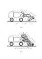
На фиг. 1 схематично изображена подметально-уборочная машина в транспортном положении, вид в разрезе сбоку.In FIG. 1 is a schematic side view of a sweeper in transport position.
На фиг. 2 схематично изображена подметально-уборочная машина в рабочем положении, вид в разрезе сбоку.In FIG. 2 schematically shows a sweeper in working position, a side sectional view.
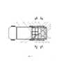
На фиг. 3 схематично изображена подметально-уборочная машина, вид в разрезе сверху.In FIG. 3 is a schematic view of a sweeper, in sectional view from above.
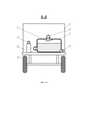
На фиг. 4 схематично изображена подметально-уборочная машина, вид сзади.In FIG. 4 is a schematic view of a sweeper, rear view.
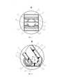
На фиг. 5 схематично изображена часть элеватора с выполненным в его верхней части сбросным козырьком, вид в разрезе сбоку.In FIG. 5 schematically shows a part of the elevator with a discharge hood made in its upper part, a side view in section.
На фиг. 6 схематично изображена часть элеватора с выполненным в его верхней части сбросным козырьком, вид в разрезе сверху.In FIG. 6 schematically shows a part of the elevator with a discharge hood made in its upper part, a top sectional view.
На фиг. 7 схематично изображено размещение конвейерной ленты со штангами, снабженными роликами, во внутренней полости элеватора, вид в поперечном разрезе.In FIG. 7 schematically shows the placement of a conveyor belt with rods equipped with rollers in the internal cavity of the elevator, a cross-sectional view.
На фиг. 8 схематично изображена часть элеватора с выполненной в его нижней части зубчатой кареткой, вид в разрезе сбоку.In FIG. 8 schematically shows a part of the elevator with a gear carriage made in its lower part, a side view in section.
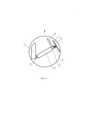
На фиг. 9 схематично изображено крепление винтового домкрата, вид сбоку.In FIG. 9 schematically shows the fastening of the screw jack, side view.
На фиг. 10 схематично изображено размещение воздушного компрессора и мусоронакопительной камеры на грузовой платформе шасси автомобиля, вид в разрезе сзади.In FIG. 10 schematically shows the placement of an air compressor and a waste chamber on a cargo platform of a vehicle chassis, a rear sectional view.
На фиг. 11 схематично изображен приводной элемент подметально-уборочной машины, вид в разрезе сверху.In FIG. 11 schematically shows the drive element of a sweeper, a top sectional view.
На фиг. 1-11 применены следующие обозначения:In FIG. 1-11 the following notation is used:
1 - элеватор;1 - elevator;
2 - сбросной козырек;2 - discharge visor;
3 - конвейерная лента;3 - conveyor belt;
4 - ворсистый скребок;4 - fleecy scraper;
5 - боковина;5 - sidewall;
6 - верхнее перекрытие;6 - top floor;
7 - нижнее перекрытие;7 - bottom overlap;
8 - подпружиненная шторка;8 - spring-loaded curtain;
9 - приводное колесо;9 - drive wheel;
10 - винтовой домкрат;10 - screw jack;
11 - стойка;11 - rack;
12 - петля;12 - loop;
13 - бункер;13 - bunker;
14 - перфорированная лента;14 - perforated tape;
15 - штанга;15 - rod;
16 - ролик;16 - roller;
17 - верхняя направляющая;17 - top guide;
18 - нижняя направляющая;18 - bottom guide;
19 - натяжной барабан;19 - tension drum;
20 - опора;20 - support;
21 - зубчатая каретка;21 - gear carriage;
22 - цилиндрическая щетка;22 - cylindrical brush;
23 - щиток;23 - shield;
24 - вытяжной купол;24 - exhaust dome;
25 - вытяжной патрубок;25 - exhaust pipe;
26 - эжектор;26 - ejector;
27 - камера смешивания;27 - mixing chamber;
28 - воздушный компрессор;28 - air compressor;
29 - напорный воздушный шланг;29 - pressure air hose;
30 - впускной воздушный шланг;30 - inlet air hose;
31 - мусоронакопительная камера;31 - garbage collection chamber;
32 - выпускной воздушный шланг;32 - outlet air hose;
33 - несущий кожух;33 - bearing casing;
34 - ведущий вал;34 - drive shaft;
35 - каретный вал;35 - carriage shaft;
36 - шарнир;36 - hinge;
37 - винт;37 - screw;
38 - рукоятка;38 - handle;
39 - амортизирующая пружина;39 - damping spring;
40 - пята;40 - heel;
41 - отбойник;41 - chipper;
42 - щеточный вал;42 - brush shaft;
43 - основная ведущая шестерня;43 - main drive gear;
44 - основная ведомая шестерня;44 - main driven gear;
45 - распределительный вал;45 - camshaft;
46 - каретная ведущая шестерня;46 - carriage drive gear;
47 - каретная ведомая шестерня;47 - carriage driven gear;
48 - щеточная ведущая шестерня;48 - brush drive gear;
49 - щеточная ведомая шестерня;49 - brush driven gear;
50 - кронштейн;50 - bracket;
51 - каток;51 - ice rink;
52 - сливной патрубок с запорным краном.52 - drain pipe with stopcock.
Подметально-уборочная машина работает следующим образом.Sweeper works as follows.
Монтаж элемента для сбора мусора выполняют в следующей последовательности. К одной из боковин 5 элеватора 1, перпендикулярно к ней и параллельно плоскостям намечаемого расположения верхнего 6 и нижнего 7 перекрытий элеватора 1 на расстояниях от них, обеспечивающих свободное движение конвейерной ленты, 3 с ворсистыми скребками 4, жестко присоединяют одну из боковых сторон верхней направляющей 17 и параллельно ей - одну из нижних направляющих 18. В сбросном козырьке 2 на конце каждой нижней направляющей 18, а также на конце верхней направляющей 17 устанавливают опоры 20 с подвижно закрепленными по обеим сторонам каждой из них натяжными барабанами 19 с обеспечением возможности свободного перемещения штанг 15 с роликами 16 конвейерной ленты 3 между концами нижней 18 и верхней 17 направляющих с натяжными барабанами 19 на опорах 20. Каждую из двух нижних направляющих 18 выполняют шириной, при которой ее свободный конец находится на расстоянии от штанг 15, равном толщине их вертикальных частей. Радиус натяжного барабана 19 и расстояние между верхними концами верхней 17 и нижней 18 направляющими принимают исходя из обеспечения возможности свободного перемещения между ними штанг 15 с роликами 16. На конвейерной ленте 3 параллельно ее продольной оси на удалении от ближайшего края конвейерной ленты 3, примерно равном 0,35 ее ширины, закрепляют две перфорированные ленты 14. На наружной поверхности конвейерной ленты 3 перпендикулярно ее оси на равном удалении друг от друга закрепляют ворсистые скребки 4 таким образом, чтобы они не перекрывали перфорацию перфорированной ленты 14. При этом каждый ворсистый скребок 4 выполняют длиной, равной ширине конвейерной ленты 3, а его нижнюю часть выполняют в жесткой конструкции. Конвейерную ленту 3 снабжают попарно устанавливаемыми штангами 15 Г-образной формы, для чего их вертикальные части пропускают через конвейерную ленту 3 перпендикулярно ее поверхности и их торцы неподвижно присоединяют к нижней части каждого ворсистого скребка 4 на расстоянии от каждого из его концов, примерно соответствующем положению линии, проходящей вдоль свободного конца ближайшей нижней направляющей 18 на расстоянии от нее, примерно равном толщине вертикальных частей штанг 15. Торцы горизонтальных частей штанг 15 снабжают роликами 16 и направляют в сторону ближайшей боковины 5. На верхнюю 17 и нижнюю 18 направляющие устанавливают смонтированную конвейерную ленту 3 таким образом, чтобы на восходящем участке конвейера 3 и на верхней части сбросного козырька 2 ролики 16 опирались на верхние поверхности верхней направляющей 17, а на нисходящем участке конвейера 3 - на верхние поверхности нижних направляющих 18. Вторую боковину 5 с предварительно закрепленной на ней второй нижней направляющей 18 неподвижно закрепляют на свободной боковой стороне верхней направляющей 17. На торцевых частях боковин 5 неподвижно закрепляют верхнее 6 и нижнее 7 перекрытия, образовывая тем самым несущий короб элеватора 1, грани которого располагаются параллельно боковым, нижним и верхним поверхностям элеватора 1 и сбросного козырька 2 на расстояниях от них, обеспечивающих свободное движение конвейерной ленты 3 с ворсистыми скребками 4. К нижнему ребру верхнего перекрытия 6 подвижно присоединяют подпружиненную шторку 8 выполненную в поперечном разрезе дугообразной формы с радиусом, равным радиусу зубчатой каретки, увеличенному на высоту ворсистого скребка, и снабженную двумя катками 51, установленными по краям в ее нижней части.The garbage collection element is installed in the following sequence. To one of the
К заднему борту кузова 13 на равном удалении друг от друга неподвижно присоединяют три стойки 11, к верхним частям которых присоединяют три петли 12, свободные карты которых присоединяют к нижнему перекрытию 7 на высоте от его нижней части, при которой концы ворсистого скребка 4 при его нахождении в крайнем нижнем положении соприкасались с поверхностью проезжей части.Three
К винту 37 винтового домкрата 10 неподвижно присоединяют рукоятку 38, а на его торце подвижно закрепляют пяту 40 с возможностью ее вращения вокруг своей оси, к которой неподвижно присоединяют амортизирующую пружину 39. Винтовой домкрат 10 подвижно присоединяют своим основанием на шарнире 36 к нижней части стойки 11, размещенной посередине заднего борта кузова 13. Свободный конец амортизирующей пружины 39 неподвижно закрепляют на нижнем перекрытии 7. К задней части грузовой платформы шасси автомобиля на равном удалении друг от друга неподвижно присоединяют в вертикальном положении три стойки 11, к верхним частям которых присоединяют три петли 12, свободные карты которых присоединяют к нижнему перекрытию 7 на высоте от его нижней части, при которой концы ворсистого скребка 4 при его нахождении в крайнем нижнем положении соприкасаются с поверхностью проезжей части. К винту 37 винтового домкрата 10 неподвижно присоединяют рукоятку 38, а на его торце подвижно закрепляют пяту 40 с возможностью ее вращения вокруг своей оси, к которой неподвижно присоединяют амортизирующую пружину 39. Винтовой домкрат 10 подвижно присоединяют своим основанием на шарнире 36 к нижней части стойки 11, размещенной посередине задней части грузовой платформы шасси автомобиля. Свободный конец амортизирующей пружины 39 неподвижно закрепляют на нижнем перекрытии 7.The
Монтаж элемента для сбора пыли выполняют в следующей последовательности. К наружной поверхности верхнего перекрытия 6, в нижней части, над намечаемым местом установки цилиндрической щетки 22 жестко закрепляют два соединенных между собой вытяжных купола 24, каждый их которых в его верхней части снабжен вытяжным патрубком 25. К свободным продольным краям вытяжных куполов 24 жестко присоединяют щиток 23, имеющий в поперечном сечении дугообразную форму, соответствующей форме наружной поверхности цилиндрической щетки 22. Свободные концы вытяжных патрубков 25 присоединяют к соответствующим камерам смешивания 27 эжектора 26. Эжектор 26 жестко закрепляют на наружной поверхности верхнего перекрытия 6. На задней части грузовой платформы шасси автомобиля устанавливают воздушный компрессор 28 и мусоронакопительную камеру 31, которую в ее нижней боковой части снабжают сливным патрубком с запорным краном 52. К внутренней поверхности обечайки мусоронакопительной камеры 31 в месте присоединения выпускного воздушного шланга 32 жестко присоединяют один край отбойника 41, имеющего в продольном разрезе дугообразную форму. Напорный воздушный шланг 29 одним своим концом присоединяют к воздушному компрессору 28, а другим концом - к средней части эжектора 26. Каждый из двух впускных шлангов 30 одним своим концом присоединяют к ближайшей торцевой части эжектора 26, а другим концом - к нижней части мусоронакопительно камеры 31. Каждый из двух выпускных воздушных шлангов 32 присоединяют своим верхним концом к верхней точке мусоронакопительной камеры 31, а нижний конец закрепляют между подпружиненной шторкой 8 и цилиндрической щеткой 22 примерно на одной горизонтальной плоскости с нижней торцевой частью подпружиненной шторки 8 таким образом, чтобы торцы нижних частей выпускных воздушных шлангов 32 были направлены в сторону друг друга.Installation of the dust collection element is carried out in the following sequence. To the outer surface of the
Монтаж приводного элемента выполняют в следующей последовательности. В каждом из двух несущих кожухов 33 подвижно закрепляют ведущий вал 34 с жестко установленной на нем основной ведущей шестерней 43, каретный вал 35 с жестко установленной на нем каретной ведомой шестерней 47, щеточный вал 42 с жестко установленной на нем щеточной ведомой шестерней 49, распределительный вал 45 на двух жестко присоединенных к внутренней поверхности несущего кожуха 33 кронштейнах 50, снабженный жестко установленными на нем основной ведомой шестерней 44, каретной 46 и щеточной 48 ведущими шестернями. Зубчатые связи основной ведущей шестерни 43 с основной ведомой шестерней и каретной ведущей шестерни 46 с каретной ведомой шестерней 47 выполняют с возможностью вращения ведущего 34 и каретного 35 валов в одном направлении. Зубчатую связь щеточных ведущей 48 и ведомой 49 шестерней выполняют с возможностью вращения ведущего 34 и щеточного 42 валов в противоположных направлениях. Диаметры основных ведомых шестерней 44 выполняют примерно равными 0,6 диаметра основных ведущих шестерней 43, а диаметры каретных 46 и щеточных 48 ведущих шестерней и диаметры ведомых каретных 47 и щеточных 49 шестерней выполняют равными диаметрам основных ведомых шестерней 44. Каретный вал 35 помещают между восходящим и нисходящим участками конвейерной ленты 3 таким образом, чтобы перфорация перфорированных лент 14 совпадала с зубьями зубчатой каретки 21. Оба несущих кожуха 33 жестко присоединяют к боковинам 5 несущего короба элемента для сбора мусора, на концах ведущего вала 34 неподвижно устанавливают приводные колеса 9.The drive element is mounted in the following sequence. In each of the two bearing
На передней части грузовой платформы шасси автомобиля устанавливают бункер 13 трапецевидной в продольном сечении формы таким образом, чтобы его задний верхний край находился под установленным в верхней части элеватора 1 сбросным козырьком 2.On the front part of the loading platform of the vehicle chassis, a
Для перевода подметально-уборочной машины в транспортное положение вращают рукоятку 38 винта 37 винтового домкрата 10, перемещающегося по дуге на шарнире 36, и поднимают соединенные между собой элемент для сбора мусора, элемент для сбора пыли и приводной элемент по дуге вокруг петлей 12 на стойках 11 до достижения низом приводных колес 9 безопасного расстояния от поверхности проезжей части.To transfer the sweeper to the transport position, the
Для перевода подметально-уборочной машины в рабочее положение рукоятку 38 винта 37 винтового домкрата 10 вращают до соприкосновения приводных колес 9 и катков 51 на подпружиненной шторке 8 с поверхностью проезжей части, наполняют водой мусоронакопительную камеру 31 примерно на 2/3 ее объема и включают воздушный компрессор 28. В процессе движения шасси автомобиля в результате вращения приводных колес 9 и ведущего вала 34 приводят во вращение установленные внутри несущего кожуха 33 конические зубчатые связи основных ведущих шестерней 43 с ответными основными ведомыми шестернями 44, распределительные валы 45 на кронштейнах 50, конические зубчатые связи каретных ведущих шестерней 46 с ответными каретными ведомыми шестернями 47, а также щеточных ведущих шестерней 48 с ответными щеточными ведомыми шестернями 49. В результате приводят во вращение каретный 35 и щеточный 42 валы. Вращение каретного вала 35 в одном направлении с вращением ведущего вала 34 передают на зубчатые каретки 21, которые, вступая в зацепление с перфорированной лентой 14, приводят в движение конвейерную ленту 3, восходящий участок которой на роликах 16, закрепленных на штангах 15, перемещается по верхней направляющей 17 в сторону сбросного козырька 2 элеватора 1 и далее - в бункер 13, а нисходящий участок конвейерной ленты 3 по нижним направляющим 18 перемещается в обратную сторону. Натяжение конвейерной ленты 3 регулируют натяжными барабанами 19 на опорах 20. Ворсистые скребки 4 по мере перемещения конвейерной ленты 3 поочередно захватывают находящийся на проезжей части мусор и перемещают его по восходящему участку конвейерной ленты 3 в бункер 13. Несущий короб, образованный боковинами 5, верхним 6 и нижним 7 перекрытиями, предотвращает потери, мусора при его перемещении по конвейерной ленте 3 в результате ветровых и вибрационных воздействий. Подпружиненная шторка 8 на катках 51 ограничивает выход захватываемого ворсистыми скребками 4 мусора, размеры которого превышают величину зазора между низом подпружиненной шторки 8 и верхом дорожного покрытия, в сторону цилиндрической щетки 22, которая, вращаясь в сторону, противоположную направлению вращения конвейерной ленты 3, захватывает с поверхности дорожного покрытия пыль и мелкий мусор, не захваченный ворсистыми скребками 4 конвейерной ленты 3, и подает их к вытяжным куполам 24. Одновременно воздух, поступающий из направленных в сторону друг друга торцов нижних частей выпускных воздушных шлангов 32, способствует перемещению частиц пыли и мелкого мусора к вытяжным куполам 24 и предотвращает их выход за боковые габариты элемента для сбора пыли, а щиток 23 предотвращает их выход за заднюю часть цилиндрической щетки 22. За счет разряжения, создаваемого в камерах смешивания 27, в результате подачи сжатого воздуха из воздушного компрессора 28 по напорному воздушному шлангу 29 в эжектор 26 пыль и мелкий мусор из вытяжных куполов 24 по вытяжным патрубкам 25 поступает в камеры смешивания 27 и далее по эжектору 26 и впускным воздушным шлангам 30 - в мусоронакопительную камеру 31. Поступившие в мусоронакопительную камеру 31 пыль и мелкий мусор за счет их смачивания водой остаются внутри мусоронакопительной камеры 31, а воздух, поступающий по впускным воздушным шлангам 30, поднимается через столб воды и выходит в выпускные воздушные шланги 32. При этом отбойник 41 предотвращает попадание во внутреннюю полость выпускных воздушных шлангов 32 воды с пылью и мелким мусором.To transfer the sweeper to the working position, the
Возникающую в процессе движения подметально-уборочной машины вибрацию, обусловленную неровностями поверхности проезжей части, погашает амортизирующая пружина 39, закрепленная на пяте 40 винта 37 винтового домкрата 10, обеспечивая тем самым постоянное сцепление приводных колес 9 с поверхностью проезжей части и, как следствие, непрерывное перемещение конвейерной ленты 3 и вращение цилиндрической щетки 22. После завершения работы подметально-уборочной машины ее переводят в транспортное положение через сливной патрубок с запорным краном 52 сливают из мусоронакопительной камеры 31 воду с содержащимися в ней пылью и мелким мусором и вновь заполняют мусоронакопительную камеру 21 водой.The vibration arising during the movement of the sweeper and harvester, due to unevenness of the surface of the roadway, is extinguished by the shock-absorbing
Таким образом, в результате реализации предложенного технического решения обеспечивается повышение качества уборки улиц и тротуаров при одновременном снижении негативного воздействия на окружающую природную среду в процессе уборки за счет раздельного сбора мусора и пыли и минимизации их потерь в результате ветровых и вибрационных воздействий путем выполнения подметально-уборочной машины из элементов для сбора мусора и пыли, заключения элеватора и сбросного козырька элемента для сбора мусора в короб, применения в элементе для сбора пыли замкнутой системы вакуумной уборки, предотвращающей выход в окружающую природную среду собираемых частиц пыли и мелкого мусора.Thus, as a result of the implementation of the proposed technical solution, it is ensured that the quality of cleaning streets and sidewalks is improved while reducing the negative impact on the environment during the cleaning process due to the separate collection of garbage and dust and minimizing their losses as a result of wind and vibration effects by performing sweeping and harvesting machines from elements for collecting garbage and dust, enclosing the elevator and the discharge hood of the element for collecting garbage in a box, using a closed vacuum cleaning system in the element for collecting dust, which prevents the collected dust particles and small debris from escaping into the environment.
Claims (1)
Translated fromRussianPriority Applications (1)
| Application Number | Priority Date | Filing Date | Title |
|---|---|---|---|
| RU2021123464ARU2765998C1 (en) | 2021-08-06 | 2021-08-06 | Sweeper |
Applications Claiming Priority (1)
| Application Number | Priority Date | Filing Date | Title |
|---|---|---|---|
| RU2021123464ARU2765998C1 (en) | 2021-08-06 | 2021-08-06 | Sweeper |
Publications (1)
| Publication Number | Publication Date |
|---|---|
| RU2765998C1true RU2765998C1 (en) | 2022-02-07 |
Family
ID=80445478
Family Applications (1)
| Application Number | Title | Priority Date | Filing Date |
|---|---|---|---|
| RU2021123464ARU2765998C1 (en) | 2021-08-06 | 2021-08-06 | Sweeper |
Country Status (1)
| Country | Link |
|---|---|
| RU (1) | RU2765998C1 (en) |
Cited By (3)
| Publication number | Priority date | Publication date | Assignee | Title |
|---|---|---|---|---|
| CN115288064A (en)* | 2022-07-06 | 2022-11-04 | 泰州市佳洁环保科技有限公司 | Intelligent road garbage cleaning vehicle |
| CN116352937A (en)* | 2023-04-17 | 2023-06-30 | 胜利油田长龙橡塑有限责任公司 | Cold setting device of aramid fiber cotton rope reinforcing V area production for oil field beam-pumping unit |
| RU221373U1 (en)* | 2023-06-15 | 2023-11-02 | Александр Владимирович Белогорцев | VACUUM SWEEPER WITH DIESEL DRIVE |
Citations (7)
| Publication number | Priority date | Publication date | Assignee | Title |
|---|---|---|---|---|
| SU1331936A1 (en)* | 1985-12-09 | 1987-08-23 | Ю.В.Корчагин, В.В.Ткачук и В.В.Литвинов | Sweeping machine |
| SU1574717A1 (en)* | 1988-07-08 | 1990-06-30 | Научно-Исследовательский И Конструкторско-Технологический Институт Городского Хозяйства Министерства Жилищно-Коммунального Хозяйства Усср | Road sweeper |
| JP2002081035A (en)* | 2000-09-07 | 2002-03-22 | Mentekku:Kk | Road sweeper, and road surface cleaning method |
| CN201390940Y (en)* | 2009-04-18 | 2010-01-27 | 中国重型汽车集团唐山市宏远专用汽车有限公司 | Fully-sealed groove-shaped scraping plate-type garbage collecting and conveying device |
| CN110130252A (en)* | 2018-02-09 | 2019-08-16 | 极地雪龙环境技术有限公司 | Road quick sweeper and its cleaning method |
| RU2721270C1 (en)* | 2017-04-14 | 2020-05-18 | Шварце Индастрис, Инк. | Road sweeping machine with several sweeping modes |
| CN211621383U (en)* | 2019-12-27 | 2020-10-02 | 山东东岳专用汽车制造有限公司 | Synchronizing wheel and scraper type material lifting device applying same |
- 2021
- 2021-08-06RURU2021123464Apatent/RU2765998C1/enactive
Patent Citations (7)
| Publication number | Priority date | Publication date | Assignee | Title |
|---|---|---|---|---|
| SU1331936A1 (en)* | 1985-12-09 | 1987-08-23 | Ю.В.Корчагин, В.В.Ткачук и В.В.Литвинов | Sweeping machine |
| SU1574717A1 (en)* | 1988-07-08 | 1990-06-30 | Научно-Исследовательский И Конструкторско-Технологический Институт Городского Хозяйства Министерства Жилищно-Коммунального Хозяйства Усср | Road sweeper |
| JP2002081035A (en)* | 2000-09-07 | 2002-03-22 | Mentekku:Kk | Road sweeper, and road surface cleaning method |
| CN201390940Y (en)* | 2009-04-18 | 2010-01-27 | 中国重型汽车集团唐山市宏远专用汽车有限公司 | Fully-sealed groove-shaped scraping plate-type garbage collecting and conveying device |
| RU2721270C1 (en)* | 2017-04-14 | 2020-05-18 | Шварце Индастрис, Инк. | Road sweeping machine with several sweeping modes |
| CN110130252A (en)* | 2018-02-09 | 2019-08-16 | 极地雪龙环境技术有限公司 | Road quick sweeper and its cleaning method |
| CN211621383U (en)* | 2019-12-27 | 2020-10-02 | 山东东岳专用汽车制造有限公司 | Synchronizing wheel and scraper type material lifting device applying same |
Cited By (7)
| Publication number | Priority date | Publication date | Assignee | Title |
|---|---|---|---|---|
| CN115288064A (en)* | 2022-07-06 | 2022-11-04 | 泰州市佳洁环保科技有限公司 | Intelligent road garbage cleaning vehicle |
| CN115288064B (en)* | 2022-07-06 | 2023-10-27 | 泰州市佳洁环保科技有限公司 | Intelligent rubbish clearance car of road |
| CN116352937A (en)* | 2023-04-17 | 2023-06-30 | 胜利油田长龙橡塑有限责任公司 | Cold setting device of aramid fiber cotton rope reinforcing V area production for oil field beam-pumping unit |
| CN116352937B (en)* | 2023-04-17 | 2023-11-03 | 胜利油田长龙橡塑有限责任公司 | Cold setting device of aramid fiber cotton rope reinforcing V area production for oil field beam-pumping unit |
| RU221373U1 (en)* | 2023-06-15 | 2023-11-02 | Александр Владимирович Белогорцев | VACUUM SWEEPER WITH DIESEL DRIVE |
| RU221372U1 (en)* | 2023-06-15 | 2023-11-02 | Александр Владимирович Белогорцев | VACUUM SWEEPER WITH ELECTRIC DRIVE |
| RU2843953C1 (en)* | 2024-06-14 | 2025-07-22 | Общество с ограниченной ответственностью "Геркулес" | Vacuum-cleaning sweeping machine |
Similar Documents
| Publication | Publication Date | Title |
|---|---|---|
| US4754521A (en) | Street sweeper machine for trash collecting | |
| RU2765998C1 (en) | Sweeper | |
| CA2475362C (en) | Debris collection systems, vehicles, and methods | |
| KR100901150B1 (en) | Multifunctional Low Rise Road Cleaning Car | |
| US20080066781A1 (en) | Stripe removal system | |
| CN111119103B (en) | Cleaning vehicle | |
| HU215003B (en) | Machine for machining material in track bed | |
| CN104499450A (en) | Waste sweeper | |
| RU2755281C1 (en) | Self-propelled garbage collection machine | |
| US3186016A (en) | Street sweeping machine | |
| JP2620552B2 (en) | Road vacuum cleaner to collect garbage | |
| US3222706A (en) | Sweeping machine | |
| CN113279355B (en) | Road garbage fast sweeper | |
| CN116237281B (en) | Roadway cleaning dust collection vehicle | |
| CN219218815U (en) | Road surface garbage quick cleaning vehicle | |
| CN216193824U (en) | High efficiency pitch unloading paving equipment | |
| US3708823A (en) | Street and parking lot cleaner attachment for vehicles | |
| CN111485527B (en) | Beach cleaning device capable of realizing common cleaning function of multiple kinds of garbage | |
| CN205617293U (en) | Take guardrail belt cleaning device's multi -functional road surface sweeping vehicle | |
| CN209211368U (en) | A kind of city road sanitation vehicle | |
| RU2843953C1 (en) | Vacuum-cleaning sweeping machine | |
| CN115288032B (en) | Bridge deck epoxy asphalt paving equipment | |
| RU2614878C1 (en) | Small-size municipal vehicle | |
| CN222100710U (en) | An unmanned road sweeper for highway maintenance | |
| CN212956309U (en) | Garbage sweeping and collecting device and garbage sweeping and collecting vehicle with same |