RU2765591C2 - Inhaler and inhaler cartridge - Google Patents
Inhaler and inhaler cartridgeDownload PDFInfo
- Publication number
- RU2765591C2 RU2765591C2RU2018106929ARU2018106929ARU2765591C2RU 2765591 C2RU2765591 C2RU 2765591C2RU 2018106929 ARU2018106929 ARU 2018106929ARU 2018106929 ARU2018106929 ARU 2018106929ARU 2765591 C2RU2765591 C2RU 2765591C2
- Authority
- RU
- Russia
- Prior art keywords
- liquid
- container
- heater
- paragraphs
- aerosol
- Prior art date
Links
Images

Classifications
- A—HUMAN NECESSITIES
- A24—TOBACCO; CIGARS; CIGARETTES; SIMULATED SMOKING DEVICES; SMOKERS' REQUISITES
- A24F—SMOKERS' REQUISITES; MATCH BOXES; SIMULATED SMOKING DEVICES
- A24F40/00—Electrically operated smoking devices; Component parts thereof; Manufacture thereof; Maintenance or testing thereof; Charging means specially adapted therefor
- A24F40/30—Devices using two or more structurally separated inhalable precursors, e.g. using two liquid precursors in two cartridges
- A—HUMAN NECESSITIES
- A24—TOBACCO; CIGARS; CIGARETTES; SIMULATED SMOKING DEVICES; SMOKERS' REQUISITES
- A24B—MANUFACTURE OR PREPARATION OF TOBACCO FOR SMOKING OR CHEWING; TOBACCO; SNUFF
- A24B15/00—Chemical features or treatment of tobacco; Tobacco substitutes, e.g. in liquid form
- A24B15/10—Chemical features of tobacco products or tobacco substitutes
- A24B15/16—Chemical features of tobacco products or tobacco substitutes of tobacco substitutes
- A24B15/167—Chemical features of tobacco products or tobacco substitutes of tobacco substitutes in liquid or vaporisable form, e.g. liquid compositions for electronic cigarettes
- A—HUMAN NECESSITIES
- A24—TOBACCO; CIGARS; CIGARETTES; SIMULATED SMOKING DEVICES; SMOKERS' REQUISITES
- A24F—SMOKERS' REQUISITES; MATCH BOXES; SIMULATED SMOKING DEVICES
- A24F40/00—Electrically operated smoking devices; Component parts thereof; Manufacture thereof; Maintenance or testing thereof; Charging means specially adapted therefor
- A24F40/10—Devices using liquid inhalable precursors
- A—HUMAN NECESSITIES
- A24—TOBACCO; CIGARS; CIGARETTES; SIMULATED SMOKING DEVICES; SMOKERS' REQUISITES
- A24F—SMOKERS' REQUISITES; MATCH BOXES; SIMULATED SMOKING DEVICES
- A24F40/00—Electrically operated smoking devices; Component parts thereof; Manufacture thereof; Maintenance or testing thereof; Charging means specially adapted therefor
- A24F40/20—Devices using solid inhalable precursors
- A—HUMAN NECESSITIES
- A24—TOBACCO; CIGARS; CIGARETTES; SIMULATED SMOKING DEVICES; SMOKERS' REQUISITES
- A24F—SMOKERS' REQUISITES; MATCH BOXES; SIMULATED SMOKING DEVICES
- A24F40/00—Electrically operated smoking devices; Component parts thereof; Manufacture thereof; Maintenance or testing thereof; Charging means specially adapted therefor
- A24F40/40—Constructional details, e.g. connection of cartridges and battery parts
- A24F40/42—Cartridges or containers for inhalable precursors
- A—HUMAN NECESSITIES
- A24—TOBACCO; CIGARS; CIGARETTES; SIMULATED SMOKING DEVICES; SMOKERS' REQUISITES
- A24F—SMOKERS' REQUISITES; MATCH BOXES; SIMULATED SMOKING DEVICES
- A24F40/00—Electrically operated smoking devices; Component parts thereof; Manufacture thereof; Maintenance or testing thereof; Charging means specially adapted therefor
- A24F40/40—Constructional details, e.g. connection of cartridges and battery parts
- A24F40/44—Wicks
- A—HUMAN NECESSITIES
- A24—TOBACCO; CIGARS; CIGARETTES; SIMULATED SMOKING DEVICES; SMOKERS' REQUISITES
- A24F—SMOKERS' REQUISITES; MATCH BOXES; SIMULATED SMOKING DEVICES
- A24F40/00—Electrically operated smoking devices; Component parts thereof; Manufacture thereof; Maintenance or testing thereof; Charging means specially adapted therefor
- A24F40/40—Constructional details, e.g. connection of cartridges and battery parts
- A24F40/46—Shape or structure of electric heating means
- A—HUMAN NECESSITIES
- A61—MEDICAL OR VETERINARY SCIENCE; HYGIENE
- A61M—DEVICES FOR INTRODUCING MEDIA INTO, OR ONTO, THE BODY; DEVICES FOR TRANSDUCING BODY MEDIA OR FOR TAKING MEDIA FROM THE BODY; DEVICES FOR PRODUCING OR ENDING SLEEP OR STUPOR
- A61M11/00—Sprayers or atomisers specially adapted for therapeutic purposes
- A61M11/04—Sprayers or atomisers specially adapted for therapeutic purposes operated by the vapour pressure of the liquid to be sprayed or atomised
- A61M11/041—Sprayers or atomisers specially adapted for therapeutic purposes operated by the vapour pressure of the liquid to be sprayed or atomised using heaters
- A61M11/042—Sprayers or atomisers specially adapted for therapeutic purposes operated by the vapour pressure of the liquid to be sprayed or atomised using heaters electrical
- A—HUMAN NECESSITIES
- A61—MEDICAL OR VETERINARY SCIENCE; HYGIENE
- A61M—DEVICES FOR INTRODUCING MEDIA INTO, OR ONTO, THE BODY; DEVICES FOR TRANSDUCING BODY MEDIA OR FOR TAKING MEDIA FROM THE BODY; DEVICES FOR PRODUCING OR ENDING SLEEP OR STUPOR
- A61M11/00—Sprayers or atomisers specially adapted for therapeutic purposes
- A61M11/04—Sprayers or atomisers specially adapted for therapeutic purposes operated by the vapour pressure of the liquid to be sprayed or atomised
- A61M11/041—Sprayers or atomisers specially adapted for therapeutic purposes operated by the vapour pressure of the liquid to be sprayed or atomised using heaters
- A61M11/045—Sprayers or atomisers specially adapted for therapeutic purposes operated by the vapour pressure of the liquid to be sprayed or atomised using heaters using another liquid as heat exchanger, e.g. bain-marie
- A—HUMAN NECESSITIES
- A61—MEDICAL OR VETERINARY SCIENCE; HYGIENE
- A61M—DEVICES FOR INTRODUCING MEDIA INTO, OR ONTO, THE BODY; DEVICES FOR TRANSDUCING BODY MEDIA OR FOR TAKING MEDIA FROM THE BODY; DEVICES FOR PRODUCING OR ENDING SLEEP OR STUPOR
- A61M15/00—Inhalators
- A61M15/0001—Details of inhalators; Constructional features thereof
- A61M15/0003—Details of inhalators; Constructional features thereof with means for dispensing more than one drug
- A—HUMAN NECESSITIES
- A61—MEDICAL OR VETERINARY SCIENCE; HYGIENE
- A61M—DEVICES FOR INTRODUCING MEDIA INTO, OR ONTO, THE BODY; DEVICES FOR TRANSDUCING BODY MEDIA OR FOR TAKING MEDIA FROM THE BODY; DEVICES FOR PRODUCING OR ENDING SLEEP OR STUPOR
- A61M15/00—Inhalators
- A61M15/06—Inhaling appliances shaped like cigars, cigarettes or pipes
- F—MECHANICAL ENGINEERING; LIGHTING; HEATING; WEAPONS; BLASTING
- F22—STEAM GENERATION
- F22B—METHODS OF STEAM GENERATION; STEAM BOILERS
- F22B1/00—Methods of steam generation characterised by form of heating method
- F22B1/28—Methods of steam generation characterised by form of heating method in boilers heated electrically
- F22B1/284—Methods of steam generation characterised by form of heating method in boilers heated electrically with water in reservoirs
- H—ELECTRICITY
- H05—ELECTRIC TECHNIQUES NOT OTHERWISE PROVIDED FOR
- H05B—ELECTRIC HEATING; ELECTRIC LIGHT SOURCES NOT OTHERWISE PROVIDED FOR; CIRCUIT ARRANGEMENTS FOR ELECTRIC LIGHT SOURCES, IN GENERAL
- H05B3/00—Ohmic-resistance heating
- H05B3/40—Heating elements having the shape of rods or tubes
- H05B3/42—Heating elements having the shape of rods or tubes non-flexible
- H05B3/44—Heating elements having the shape of rods or tubes non-flexible heating conductor arranged within rods or tubes of insulating material
- A—HUMAN NECESSITIES
- A61—MEDICAL OR VETERINARY SCIENCE; HYGIENE
- A61M—DEVICES FOR INTRODUCING MEDIA INTO, OR ONTO, THE BODY; DEVICES FOR TRANSDUCING BODY MEDIA OR FOR TAKING MEDIA FROM THE BODY; DEVICES FOR PRODUCING OR ENDING SLEEP OR STUPOR
- A61M16/00—Devices for influencing the respiratory system of patients by gas treatment, e.g. ventilators; Tracheal tubes
- A61M16/10—Preparation of respiratory gases or vapours
- A61M16/105—Filters
- A61M16/106—Filters in a path
- A61M16/107—Filters in a path in the inspiratory path
- A—HUMAN NECESSITIES
- A61—MEDICAL OR VETERINARY SCIENCE; HYGIENE
- A61M—DEVICES FOR INTRODUCING MEDIA INTO, OR ONTO, THE BODY; DEVICES FOR TRANSDUCING BODY MEDIA OR FOR TAKING MEDIA FROM THE BODY; DEVICES FOR PRODUCING OR ENDING SLEEP OR STUPOR
- A61M21/00—Other devices or methods to cause a change in the state of consciousness; Devices for producing or ending sleep by mechanical, optical, or acoustical means, e.g. for hypnosis
- A61M2021/0005—Other devices or methods to cause a change in the state of consciousness; Devices for producing or ending sleep by mechanical, optical, or acoustical means, e.g. for hypnosis by the use of a particular sense, or stimulus
- A61M2021/0016—Other devices or methods to cause a change in the state of consciousness; Devices for producing or ending sleep by mechanical, optical, or acoustical means, e.g. for hypnosis by the use of a particular sense, or stimulus by the smell sense
- A—HUMAN NECESSITIES
- A61—MEDICAL OR VETERINARY SCIENCE; HYGIENE
- A61M—DEVICES FOR INTRODUCING MEDIA INTO, OR ONTO, THE BODY; DEVICES FOR TRANSDUCING BODY MEDIA OR FOR TAKING MEDIA FROM THE BODY; DEVICES FOR PRODUCING OR ENDING SLEEP OR STUPOR
- A61M2205/00—General characteristics of the apparatus
- A61M2205/36—General characteristics of the apparatus related to heating or cooling
- A61M2205/3606—General characteristics of the apparatus related to heating or cooling cooled
- A—HUMAN NECESSITIES
- A61—MEDICAL OR VETERINARY SCIENCE; HYGIENE
- A61M—DEVICES FOR INTRODUCING MEDIA INTO, OR ONTO, THE BODY; DEVICES FOR TRANSDUCING BODY MEDIA OR FOR TAKING MEDIA FROM THE BODY; DEVICES FOR PRODUCING OR ENDING SLEEP OR STUPOR
- A61M2205/00—General characteristics of the apparatus
- A61M2205/82—Internal energy supply devices
- A61M2205/8206—Internal energy supply devices battery-operated
Landscapes
- Health & Medical Sciences (AREA)
- Engineering & Computer Science (AREA)
- Life Sciences & Earth Sciences (AREA)
- Animal Behavior & Ethology (AREA)
- Anesthesiology (AREA)
- Biomedical Technology (AREA)
- Heart & Thoracic Surgery (AREA)
- Hematology (AREA)
- General Health & Medical Sciences (AREA)
- Public Health (AREA)
- Veterinary Medicine (AREA)
- Bioinformatics & Cheminformatics (AREA)
- Pulmonology (AREA)
- Pharmacology & Pharmacy (AREA)
- General Chemical & Material Sciences (AREA)
- Chemical Kinetics & Catalysis (AREA)
- Chemical & Material Sciences (AREA)
- Sustainable Development (AREA)
- Sustainable Energy (AREA)
- Physics & Mathematics (AREA)
- Thermal Sciences (AREA)
- Mechanical Engineering (AREA)
- General Engineering & Computer Science (AREA)
- Catching Or Destruction (AREA)
- Disinfection, Sterilisation Or Deodorisation Of Air (AREA)
- Nozzles (AREA)
- Extraction Or Liquid Replacement (AREA)
- Battery Electrode And Active Subsutance (AREA)
- Containers And Packaging Bodies Having A Special Means To Remove Contents (AREA)
- Cigarettes, Filters, And Manufacturing Of Filters (AREA)
- Medicinal Preparation (AREA)
- Manufacture Of Tobacco Products (AREA)
Abstract
Description
Translated fromRussianОбласть техники, к которой относится изобретениеThe field of technology to which the invention belongs
Настоящее изобретение относится к устройству для генерирования вдыхаемой среды и к способу генерирования вдыхаемой среды и картриджу для использования с устройством для генерирования вдыхаемой среды.The present invention relates to an inhalable medium generating device and a method for generating an inhalable medium and a cartridge for use with an inhalable medium generating device.
Уровень техникиState of the art
Курительные изделия, например, сигареты, сигары и т.п., сжигают табак во время курения для образования табачного дыма. Были предприняты усилия для создания альтернативы указанным изделиям, которые сжигают табак, посредством разработки изделий, которые высвобождают соединения без сжигания. Примерами таких изделий являются нагревательные устройства, которые высвобождают соединения посредством нагрева, но без сжигания материала. Материал может быть, например, табаком или другими нетабачными изделиями, которые могут содержать или не содержать никотин. В качестве другого примера можно привести так называемые устройства электронных сигарет. Эти устройства обычно содержат жидкость, которая нагревается для испарения жидкости и производства вдыхаемого пара или аэрозоля. Жидкость может содержать никотин и/или ароматизаторы и/или генерирующие аэрозоль вещества, например, глицерол. Известные устройства электронных сигарет обычно не содержат или не используют табак.Smoking products, such as cigarettes, cigars, and the like, burn tobacco during smoking to produce tobacco smoke. Efforts have been made to provide an alternative to these products that burn tobacco by developing products that release compounds without burning. Examples of such articles are heating devices which release compounds by heating but without burning the material. The material may be, for example, tobacco or other non-tobacco products, which may or may not contain nicotine. Another example is the so-called electronic cigarette devices. These devices usually contain a liquid that is heated to vaporize the liquid and produce an inhalable vapor or aerosol. The liquid may contain nicotine and/or flavorings and/or aerosol generating substances such as glycerol. Known electronic cigarette devices typically do not contain or use tobacco.
Сущность изобретенияThe essence of the invention
По первому аспекту настоящего изобретения предлагается устройство для генерирования вдыхаемой среды, содержащее:According to a first aspect of the present invention, there is provided a device for generating an inhalable medium, comprising:
контейнер для удерживания жидкости;container for holding liquid;
нагреватель для испарения жидкости, удерживаемой в контейнере;a heater for evaporating the liquid held in the container;
камеру для размещения материала; иchamber for placement of material; and
выпуск;release;
устройство имеет такую конструкцию, что во время использования жидкость, испаряемая нагревателем, проходит в виде, по меньшей мере, пара или аэрозоля через материал, помещенный в камере, для захватывания одной или нескольких составляющих частей из материала для образования выдыхаемой среды, которая выходит из выпуска.the device is designed such that, during use, the liquid vaporized by the heater passes in the form of at least a vapor or aerosol through the material placed in the chamber to capture one or more constituent parts of the material to form an exhalable medium that exits the outlet .
Это позволяет вдыхаемой среде, приобретать, например, аромат или ароматы, извлекаемые во время использования из материала, содержащегося в устройстве. В конкретном применении пар или аэрозоль, проходящий через материал, является горячим и поэтому нагревает материал для испарения одной или нескольких составляющих частей из материала, обеспечивая поглощение составляющих частей вдыхаемой средой.This allows the inhaled medium to acquire, for example, the aroma or aromas extracted during use from the material contained in the device. In a particular application, the vapor or aerosol passing through the material is hot and therefore heats the material to vaporize one or more constituents from the material, allowing the constituents to be absorbed by the inhaled medium.
В качестве конкретного неограничивающего примера материал может быть табаком или содержать табак. Отличительным признаком так называемых устройств электронных сигарет является то, что аромат вдыхаемой среды часто не имеет ничего общего или, по меньшей мере, отличается от аромата обычного табачного изделия. В случае, когда материал в варианте выполнения настоящего изобретения является табаком или содержит табак, пар или аэрозоль, который проходит через табак, захватывает табачные ароматы из материала.As a specific non-limiting example, the material may be tobacco or contain tobacco. A distinguishing feature of so-called electronic cigarette devices is that the flavor of the inhaled medium often has nothing in common with, or at least differs from, the flavor of a conventional tobacco product. In the case where the material in an embodiment of the present invention is tobacco or contains tobacco, the vapor or aerosol that passes through the tobacco traps the tobacco flavors from the material.
В варианте выполнения нагреватель для испарения жидкости, содержащейся в контейнере, выполнен с возможностью испарения жидкости.In an embodiment, the heater for vaporizing the liquid contained in the container is configured to vaporize the liquid.
В варианте выполнения устройство содержит охладитель или зону охлаждения после нагревателя и перед камерой, причем охладитель или зона охлаждения выполнены с возможностью охлаждения испаряемой жидкости для образования аэрозоля из жидких капель, который во время использования проходит через материал, помещенный в камере. Охладитель может быть выполнен с возможностью функционирования фактически в качестве теплообменника, обеспечивая восстановление тепла из пара. Восстановленное тепло можно использовать, например, для предварительного нагрева и/или способствования нагреву жидкости.In an embodiment, the device comprises a cooler or cooling zone after the heater and in front of the chamber, wherein the cooler or cooling zone is configured to cool the vaporized liquid to form an aerosol of liquid droplets which, during use, passes through the material placed in the chamber. The cooler may be configured to function effectively as a heat exchanger, recovering heat from the steam. The recovered heat can be used, for example, to preheat and/or assist in heating the liquid.
В другом варианте выполнения нагреватель для нагрева жидкости, содержащейся в контейнере, выполнен с возможностью нагрева жидкости для образования аэрозоля.In another embodiment, the heater for heating the liquid contained in the container is configured to heat the liquid to form an aerosol.
В варианте выполнения устройство содержит второй нагреватель для нагрева материала, помещенного в камеру. Это обеспечивает нагрев материала нагревателем, что способствует высвобождению соединений из материала и, как вариант, позволяет снизить температуру, которая должна использоваться для нагреваемой жидкости.In an embodiment, the device includes a second heater for heating the material placed in the chamber. This allows the material to be heated by the heater, which aids in the release of compounds from the material and optionally reduces the temperature that must be used for the liquid to be heated.
В варианте выполнения камеру можно удалять из устройства. Камера может иметь, например, форму картриджа и т.п., который содержит материал. В целом камера, содержащая материал, может, фактически, быть изделием одноразового использования, которое целиком заменяют после использования. Как вариант конструкция может быть выполнена таким образом, что пользователь удаляет камеру из устройства, заменяет использованный материал в камере и затем помещает камеру обратно в устройство.In an embodiment, the camera can be removed from the device. The chamber may be in the form of a cartridge or the like, for example, which contains the material. In general, the chamber containing the material may, in fact, be a disposable item that is entirely replaced after use. Alternatively, the design may be such that the user removes the chamber from the device, replaces the used material in the chamber, and then places the chamber back into the device.
В другом варианте выполнения камера может быть несъемной без возможности удаления из устройства. В таком варианте выполнения пользователь может заменять только материал после использования.In another embodiment, the camera may be non-removable and cannot be removed from the device. In such an embodiment, the user can only replace the material after use.
В варианте выполнения контейнер для жидкости является съемным. Контейнер для жидкости может иметь форму горшка и т.п. (которая в некоторых вариантах выполнения может быть, например, кольцевой) и/или абсорбирующей набивкой и т.п. В целом контейнер для жидкости, содержащий жидкость, может быть фактически изделием одноразового использования, которое целиком заменяют после использования. Как вариант конструкция может быть выполнена таким образом, что пользователь удаляет контейнер для жидкости из устройства, заменяет использованную жидкость или дозаправляет жидкость в контейнер и затем помещает контейнер обратно в устройство.In an embodiment, the liquid container is removable. The liquid container may be in the form of a pot or the like. (which in some embodiments may be, for example, an annular) and/or an absorbent pad, and the like. In general, the liquid container containing the liquid may actually be a disposable item that is entirely replaced after use. Alternatively, the design may be such that the user removes the fluid container from the device, replaces the used fluid or refills the fluid into the container, and then places the container back into the device.
В другом варианте выполнения контейнер для жидкости может быть несъемным без возможности удаления из устройства. В таком варианте выполнения пользователь при необходимости может заменять только используемую жидкость или дозаправлять жидкость в контейнер после использования.In another embodiment, the fluid container may be non-removable and cannot be removed from the device. In such an embodiment, the user can, if necessary, replace only the used liquid or refill the liquid into the container after use.
В варианте выполнения контейнер для жидкости и камера выполнены как неразъемный узел.In an embodiment, the liquid container and the chamber are made as an integral unit.
В варианте выполнения камера содержит материал, имеющий твердую форму. Этот материал может быть, например, табаком или содержать табак.In an embodiment, the chamber contains a material having a solid shape. This material may be, for example, tobacco or contain tobacco.
В варианте выполнения контейнер удерживает жидкость, содержащую никотин.In an embodiment, the container holds liquid containing nicotine.
В варианте выполнения контейнер удерживает жидкость, которая является глицеролом или содержит глицерол.In an embodiment, the container holds a liquid that is glycerol or contains glycerol.
В варианте выполнения контейнер удерживает жидкость, которая является ароматизатором или содержит ароматизатор.In an embodiment, the container holds a liquid that is or contains a flavor.
В варианте выполнения устройство работает от батареи.In an embodiment, the device is battery operated.
В варианте выполнения конкретный или каждый нагреватель является электрическим резистивным нагревателем.In an embodiment, a specific or each heater is an electrical resistance heater.
По второму аспекту настоящего изобретения предлагается способ генерирования вдыхаемой среды с помощью устройства, содержащего контейнер, удерживающий жидкость, нагреватель для испарения жидкости, материал и выпуск; указанный способ содержит:According to a second aspect of the present invention, there is provided a method for generating an inhalable medium using a device comprising a liquid holding container, a liquid vaporization heater, a material, and an outlet; this method contains:
испарение жидкости, удерживаемой в контейнере;evaporation of the liquid held in the container;
захватывание одной или нескольких составляющих частей из материала, по меньшей мере, в паре или аэрозоле, образованном испаряемой жидкостью, посредством прохождения, по меньшей мере, пара или аэрозоля через материал для генерирования вдыхаемой среды; иcapturing one or more constituent parts of the material, at least in a vapor or aerosol formed by a vaporized liquid, by passing at least vapor or aerosol through the material to generate an inhalable environment; and
выход вдыхаемой среды из выпуска.exit of the inhaled medium from the outlet.
В варианте выполнения при нагреве жидкости, удерживаемой в контейнере, испаряется, по меньшей мере, часть жидкости. В варианте выполнения способ содержит прохождение испаряемой жидкости через охладитель или зону охлаждения устройства для образования аэрозоля из жидких капель, который проходит через материал.In an embodiment, heating the liquid held in the container vaporizes at least a portion of the liquid. In an embodiment, the method comprises passing the volatilized liquid through a cooler or cooling zone of the device to generate an aerosol of liquid droplets that passes through the material.
В варианте выполнения при нагреве жидкости, содержащейся в контейнере, испаряется жидкость для образования аэрозоля.In an embodiment, heating the liquid contained in the container vaporizes the liquid to form an aerosol.
В варианте выполнения способ содержит нагрев материала с помощью второго нагревателя устройства.In an embodiment, the method comprises heating the material with the second heater of the device.
В варианте выполнения материал содержится в устройстве в твердой форме. Материал может быть табаком или содержать табак.In an embodiment, the material is contained in the device in solid form. The material may be tobacco or contain tobacco.
В варианте выполнения жидкость содержит никотин.In an embodiment, the liquid contains nicotine.
В варианте выполнения жидкость является глицеролом или содержит глицерол.In an embodiment, the liquid is glycerol or contains glycerol.
В варианте выполнения жидкость является ароматизатором или содержит арматизатор.In an embodiment, the liquid is a flavor or contains a flavor.
По третьему аспекту настоящего изобретения предлагается картридж для использования с устройством для генерирования вдыхаемой среды, содержащий:According to a third aspect of the present invention, there is provided a cartridge for use with a device for generating an inhalable medium, comprising:
контейнер для удерживания жидкости;container for holding liquid;
приемник для размещения твердого материала;a receiver for placing solid material;
картридж расположен таким образом, что испаряемая жидкость, выходящая из контейнера, во время использования может протекать в виде, по меньшей мере, пара или аэрозоля через твердый материал, помещенный в приемник.the cartridge is positioned such that the volatilized liquid exiting the container during use can flow as at least a vapor or aerosol through the solid material placed in the receptacle.
В варианте выполнения картридж содержит нагреватель, связанный с контейнером для испарения жидкости, удерживаемой в контейнере во время использования.In an embodiment, the cartridge includes a heater associated with the container to vaporize the liquid held in the container during use.
В варианте выполнения картридж содержит нагреватель, связанный с приемником для нагрева твердого материала, помещенного в приемник во время использования.In an embodiment, the cartridge includes a heater associated with the receptacle for heating the solid material placed in the receptacle during use.
Краткое описание чертежейBrief description of the drawings
Варианты выполнения изобретения будут описаны только в качестве примера со ссылкой на приложенные чертежи, на которых:Embodiments of the invention will be described by way of example only with reference to the attached drawings, in which:
фиг. 1 – схематичный вид в продольном разрезе примера устройства для генерирования вдыхаемой среды;fig. 1 is a schematic longitudinal sectional view of an example of a device for generating an inhalable medium;
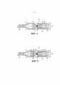
фиг. 2 – схематичный вид в продольном разрезе другого примера устройства для генерирования вдыхаемой среды;fig. 2 is a schematic longitudinal sectional view of another example of a device for generating an inhalable medium;
фиг. 3 – схематичный вид в продольном разрезе другого примера устройства для генерирования вдыхаемой среды;fig. 3 is a schematic longitudinal sectional view of another example of a device for generating an inhalable medium;
фиг. 4 – схематичный вид в продольном разрезе примера устройства для генерирования вдыхаемой среды во время использования;fig. 4 is a schematic longitudinal sectional view of an example of a device for generating an inhalable medium during use;
фиг. 5 – схематичный вид в продольном разрезе другого примера устройства для генерирования вдыхаемой среды во время использования.fig. 5 is a schematic longitudinal sectional view of another example of an apparatus for generating an inhalable medium during use.
Подробное описаниеDetailed description
Со ссылкой на фиг. 1 показан пример устройства 1 для генерирования вдыхаемой среды. В общих чертах устройство 1 испаряет жидкость для образования пара или аэрозоля, который проходит через материал для производства вдыхаемой среды, которая содержит одну или несколько составляющих, извлекаемых из указанного материала.With reference to FIG. 1 shows an example of a device 1 for generating an inhalable medium. In general terms, the device 1 vaporizes a liquid to form a vapor or aerosol that passes through a material to produce an inhalable medium that contains one or more constituents derived from said material.
В этом отношении, прежде всего, можно отметить, что, в общем, пар является веществом в газовой фазе при температуре ниже его критической температуры, а это означает, что, например, пар может конденсироваться в жидкость посредством увеличения его давления без уменьшения температуры. С другой стороны, в общем, аэрозоль является коллоидом, состоящим из мелких твердых частиц или жидких капель, содержащихся в воздухе или другом газе. “Коллоид» является веществом, в котором микроскопические рассеянные нерастворимые частицы находятся в подвешенном состоянии по всему объему другого вещества.In this regard, it can first be noted that, in general, vapor is a substance in the gas phase at a temperature below its critical temperature, which means that, for example, vapor can be condensed into a liquid by increasing its pressure without decreasing its temperature. On the other hand, in general, an aerosol is a colloid consisting of fine solid particles or liquid droplets contained in air or other gas. A “colloid” is a substance in which microscopic, dispersed insoluble particles are suspended throughout the volume of another substance.
Возвращаясь к фиг. 1, устройство 1 из этого примера имеет, в общем, полый цилиндрический наружный корпус 2. Корпус 2 имеет открытый конец 3. В этом примере в открытый конец 3 вставлен трубчатый мундштук 4. В этом примере пользователь может удалять мундштук 4 из корпуса 2. Уплотнительное кольцо круглого сечения или другое уплотнение 5 способствует герметизации мундштука 4 в корпусе 2. С другого конца 6 или вблизи этого конца корпуса 2 установлена батарея 7 для питания ряда компонентов устройства 1, как будет описано ниже. Батарея 7 может быть перезаряжаемой батареей или сменной батареей. В корпусе 2 также установлен контроллер 8 для управления работой ряда компонентов устройства 1, как будет описано ниже.Returning to FIG. 1, the device 1 of this example has a generally hollow cylindrical
Корпус 2 имеет контейнер 9 для удерживания или содержания жидкости 10. Контейнер 9 можно использовать в ряде различных форм. В примере из фиг. 1 контейнер 9 имеет форму кольцевой камеры 9, предусмотренной в корпусе 2 между открытым концом 3 и другим концом 6. В этом конкретном примере корпус 2 состоит из двух частей, первой части 2a вблизи открытого конца 3 и второй части 2b вблизи другого конца 6. Первую и вторую части 2a, 2b корпуса 2 можно соединять друг с другом с помощью винтовой резьбы, байонетного соединения и т.п. Во время использования пользователь, по мере необходимости, может разделять первую и вторую части 2a, 2b корпуса для добавления или замены жидкости. Как вариант, для обеспечения доступа к контейнеру 9 можно удалять мундштук 4. Однако следует принять во внимание, что возможны другие компоновки. Например, жидкость 10 может находиться в отдельном кольцевом контейнере горшкообразной формы, который можно целиком удалять из корпуса 2. Такой отдельный контейнер может быть сменным, так чтобы пользователь заменял жидкость 10 посредством установки нового контейнера с жидкостью 10 в корпус 2. Как вариант, такой контейнер может быть многоразовым. В таком случае пользователь может добавлять или заменять жидкость 10 в контейнере после его удаления из корпуса 2 и затем устанавливать заправленный контейнер на место в корпус 2. Следует принять во внимание, что корпус 2 необязательно должен состоять из двух частей, и что можно предусмотреть другие компоновки, обеспечивающие доступ пользователю, например для дозаправки на месте.The
В общем, по центру корпуса 2 установлен нагреватель 11, т.е. в этом примере по центру по длине и ширине корпуса 2. В этом примере нагреватель 11 запитывается от батареи 7 и, следовательно, электрически соединен с батареей 7. Нагреватель 11 может быть электрическим резистивным нагревателем, включая сюда, например, нихромный резистивный нагреватель, керамический нагреватель и т.д. Нагреватель 11 может быть, например, проволокой, которая может, например, иметь форму спирали, пластиной (которая может быть многослойной пластиной из двух или более разных материалов, один или несколько из которых могут быть электропроводными, и один или несколько из которых могут быть неэлектропроводными), сеткой (которая может быть, например, тканой или нетканой и также может быть многослойной), пленочным нагревателем и т.д. Можно использовать другие нагревательные конструкции, включая сюда неэлектрические нагревательные конструкции.In general, a
Нагреватель предназначен для испарения жидкости. В показанном примере кольцевой фитиль 12 окружает нагреватель 11 и находится в (тепловом) контакте с нагревателем 11. Самая наружная поверхность кольцевого фитиля 12 находится в контакте с жидкостью 10, содержащейся в контейнере 9 для жидкости. Фитиль 12, в общем, является абсорбирующим материалом и всасывает жидкость 10 из контейнера 9 с жидкостью посредством капиллярного эффекта. Фитиль 12 предпочтительно является нетканым и может быть, например, хлопчатобумажным материалом, шерстяным материалом и т.п. или синтетическим материалом, включая сюда, например, полиэфир, нейлон, вискозу, полипропилен и т.п. Несмотря на более полное описание, приведенное ниже, следует отметить, что во время использования жидкость 10, которая впитывается в фитиль 12, нагревается нагревателем 11. Жидкость 10 может испаряться для получения аэрозоля из жидких капель или в достаточной степени нагреваться для получения пара. Образующийся таким образом аэрозоль или пар выходит из фитиля 12 и проходит в направлении мундштука 4, как показано стрелками A, когда пользователь выполняет затяжку через мундштук 4. Нагреватель 11 и фитиль 12 могут быть изготовлены в виде отдельного фактически нераздельного компонента, так чтобы нагрев и впитывание фактически выполнялись отдельным узлом.The heater is designed to evaporate the liquid. In the example shown, the
Корпус 2 дополнительно содержит камеру 13, которая удерживает или содержит материал 14 в устройстве 1. Во время использования пользователь может иметь доступ к камере 13 для замены или заправки материала 14 через открытый конец 3 корпуса 2 посредством удаления мундштука 4 и/или разделения двух частей 2a, 2b корпуса 2. Камеру 13 можно использовать в ряде различных форм. Например, камера 13 может быть трубкой, которая полностью открыта с обоих концов и содержит материал 14. В качестве другого примера камера 13 может быть трубкой, которая имеет одну или несколько торцевых стенок, имеющих сквозные отверстия, через которые может проходить пар или аэрозоль. Камера 13 может оставаться на месте в корпусе 2, когда пользователь удаляет и заменяет материал 14. Как вариант, камера 13, содержащая указанный материал, может быть отдельным компонентом, который во время использования вставляют в корпус 2 и извлекают из него как единое целое. Съемная камера 13 этого типа может быть одноразовой, так чтобы пользователь заменял материал 14 посредством установки новой камеры 13, содержащей свежий материал 14, в корпус 2. Как вариант, камера 13 может быть многоразовой. В таком случае пользователь может заменять материал 14 в камере 13, когда камера 13 удалена из корпуса 2, и затем устанавливать заправленную камеру 13 в корпус 2. В еще одном примере камера 13 может содержать зажимы и т.п., расположенные внутри корпуса 2, которые удерживают материал 14 на месте. В некоторых примерах материал 14 может просто плотно садиться в камеру 13. В качестве другого варианта сам контейнер 9, содержащий жидкость 10, может служить в качестве опоры для материала 14. Например, контейнер 9 может иметь один или несколько зажимов или трубку и т.п. для размещения и удерживания материала 14 на месте. Такой двухфункциональный контейнер 9/камера или приемник 13 как для содержания жидкости 10, так и для размещения материала 14, может иметь форму картриджа и т.п. и может быть сменным компонентом или многоразовым компонентом с возможностью, при необходимости, замены или дозаправки жидкости 10 и материала 14 пользователем. В некоторых случаях может случиться так, что пользователю потребуется только дозаправлять или заменять материал 14 время от времени при достаточном количестве жидкости 10, предусмотренном для многоразового использования. После израсходования жидкости 10 пользователь удаляет двухфункциональный контейнер 9/приемник 13 и использует новый подобный компонент. Сходным образом, может случиться так, что пользователю потребуется только дозаправлять или заменять жидкость 10 время от времени при достаточном количестве материала 14, предусмотренном для многоразового использования. После израсходования материала 14 пользователь удаляет двухфункциональный контейнер 9/приемник 13 и использует новый подобный компонент.The
Материал 14 расположен в корпусе 2 после места, где из жидкости 10 производится аэрозоль или пар, и перед открытым концом 3 корпуса 2 и мундштуком 4. В этом конкретном примере материал 14 фактически расположен в той же части или камере корпуса 2, что и фитиль 12. Аэрозоль или пар, получаемый из жидкости 10, выходит из фитиля 12 и проходит, как показано стрелками A, в направлении материала 14, когда пользователь выполняет затяжку через мундштук 4. В конкретных вариантах выполнения материал 14 является пористым, поэтому аэрозоль или пар проходит через материал 14 и затем через открытый конец 3 корпуса 2 и мундштук 4. В некоторых вариантах выполнения материал 14 и/или его камера 13 расположены таким образом, что между материалом 14/камерой 13 и внутренней стороной корпуса 2 не существует никакого зазора, поэтому аэрозоль или пар полностью протекает через материал 14.The
Жидкость 10 предпочтительно является жидкостью, способной испаряться при соответствующих температурах, предпочтительно в диапазоне 150 - 250°C, что не допускает повышения расхода питания в устройстве 1. Пригодные материалы включают в себя материалы, обычно используемые в устройствах электронных сигарет, включая сюда, например, пропиленгликоль и глицерол (также известный как глицерин).The liquid 10 is preferably a liquid capable of being vaporized at appropriate temperatures, preferably in the range of 150-250°C, which does not allow the power consumption of the device 1 to increase. Suitable materials include those commonly used in electronic cigarette devices, including, for example, propylene glycol and glycerol (also known as glycerin).
Материал 14 является материалом, который можно использовать для придания аромата аэрозолю или пару, получаемому из жидкости 10, когда аэрозоль или пар проходит через материал 14. Материал 14 может, например, состоять из табака или содержать табак. Когда аэрозоль или пар проходит через табачный материал 14 и по табачному материалу 14, горячий аэрозоль или пар захватывает органические и другие соединения или составляющие части из табачного материала 14, которые придают табаку его органолептические свойства, тем самым, придавая аромат аэрозолю или табаку, когда он проходит к мундштуку 4. Однако следует принять во внимание, что для придания различных ароматов потоку аэрозоля или пара помимо табака можно использовать другие материалы. Например, в состав материала или жидкости могут быть включены ароматизаторы.
Кроме того, если материал 14 является табаком или включает в себя табак, может случиться так, что поток аэрозоля или пара будет вытягивать достаточно никотина из табачного материала 14. Как вариант или дополнительно, если материал 14 не содержит никакого табака, материал 14 может быть обогащен никотином, например, посредством покрытия материала никотином. Фактически, даже в случае, когда материал 14 является табаком или включает в себя табак, материал 14 может быть покрыт или иным образом обогащен никотином. В качестве другого примера, независимо от того, является ли материал 14 табаком или включает в себя табак и/или включает в себя никотин, никотин может присутствовать в жидкости 10. Соответственно, если предусматривается, что устройство 1 обеспечивает подачу никотина пользователю, никотин может присутствовать в жидкости 10, может извлекаться из материала 14 в случае, когда материал является табаком или включает в себя табак, может предусматриваться в качестве покрытия и т.п. на материале 14, который не является табаком, может предусматриваться в качестве покрытия и т.п. на табачном материале или может быть получен посредством любой комбинации указанных вариантов. Аналогично, в материал 14 и/или жидкость 10 можно добавлять ароматизаторы (независимо от того, является ли материал табаком или включает в себя табак).In addition, if the
Как указано выше, известны нагревательные устройства, которые высвобождают соединения посредством нагрева, а не сгорания табака. Можно отметить, что табак является плохим проводником тепла, при этом нагрев табака в известных устройствах для нагрева табака осуществляется посредством теплопередачи через табак от наружной поверхности табака (обычно с помощью электрического резистивного нагревательного элемента, который находится в контакте с поверхностью табака). Это означает, что табак может нагреваться неэффективно, и/или расход питания в устройстве является высоким. В случае устройства, работающего от батареи, высокий расход питания является для пользователя проблемой, поскольку ему часто приходится перезаряжать батарею или батареи. Если материал 14 является табаком, эту проблему в вариантах выполнения настоящего устройства 1 можно исключить, поскольку материал 14 можно нагревать горячим аэрозолем или паром через тело пористого табачного материала 14, обеспечивая более эффективный нагрев через тело пористого табачного материала 14. Такой нагрев может способствовать снижению расхода питания в устройстве 1.As indicated above, heating devices are known which release compounds by heating rather than by burning the tobacco. It can be noted that tobacco is a poor conductor of heat, with heating of the tobacco in known tobacco heating devices by heat transfer through the tobacco from the outer surface of the tobacco (usually by means of an electrical resistive heating element that is in contact with the surface of the tobacco). This means that the tobacco may not be heated efficiently and/or the power consumption of the device is high. In the case of a battery-operated device, high power consumption is a problem for the user because the user often has to recharge the battery or batteries. If the
В примере, показанном на фиг. 1, единственным источником тепла для нагрева материала 14 в устройстве 1, который необходим для генерирования органических и других соединений или составляющих частей из материала 14, является горячий аэрозоль или пар, получаемый в результате нагрева жидкости 10.In the example shown in FIG. 1, the only source of heat for
Со ссылкой на фиг. 2 показан другой пример устройства для генерирования вдыхаемой среды. В приведенном ниже описании и на фиг. 2 компоненты и элементы, которые являются одинаковыми или сходными с соответствующими компонентами или элементами примера, описанного со ссылкой на фиг. 1, обозначены такими же номерами позиций с добавлением числа 200. Для ясности описание этих компонентов и элементов не приводится повторно в полном объеме. Следует принять во внимание, что компоновки и вариантные решения и т.д., описанные выше в отношении примера из фиг. 1, также применимы к примеру на фиг. 2. Как и в предыдущем случае, в общих чертах устройство 201 на фиг. 2 испаряет жидкость для образования пара или аэрозоля, который проходит через материал 214 для производства вдыхаемой среды, которая содержит одну или несколько составляющих, извлекаемых из материала 214.With reference to FIG. 2 shows another example of an apparatus for generating an inhalable medium. In the description below and in FIG. 2 components and elements that are the same or similar to the corresponding components or elements of the example described with reference to FIG. 1 are designated by the same reference numbers with the addition of the number 200. For clarity, the description of these components and elements is not repeated in full. It should be appreciated that the arrangements and alternatives, etc. described above with respect to the example of FIG. 1 are also applicable to the example of FIG. 2. As in the previous case, in general terms, the
Устройство 201 из этого примера имеет, в общем, полый цилиндрический наружный корпус 202 с открытым концом 203 и трубчатым мундштуком 204. В этом примере пользователь может удалять мундштук 204 из корпуса 202, и уплотнительное кольцо круглого сечения или другое уплотнение 205 способствует герметизации мундштука 104 в корпусе 202. С другого конца 206 или вблизи этого конца корпуса 202 установлена батарея 207 для питания ряда компонентов устройства 201 и контроллер 208. В этом примере корпус 202 состоит из двух частей, первой части 202a вблизи открытого конца 203 и второй части 202b вблизи другого конца 206.The
Корпус 202 имеет контейнер 209 для удерживания или содержания жидкости 210. Контейнер 209 может быть контейнером любого типа из описанных выше типов в отношении примера из фиг. 1. Нагреватель 211 для испарения жидкости 210 расположен, в общем, по центру (по длине и ширине) корпуса 202. В этом примере нагреватель 211 запитывается от батареи 207 и, следовательно, электрически соединен с батареей 207. Нагреватель 211 может быть электрическим резистивным нагревателем, керамическим нагревателем и т.д. Нагреватель 211 может быть, например, проволокой, которая может, например, иметь форму спирали, пластиной (которая может быть многослойной пластиной из двух или более разных материалов, один или несколько из которых могут быть электропроводными, и один или несколько из которых могут быть неэлектропроводными), сеткой (которая может быть, например, тканой или нетканой и также может быть многослойной), пленочным нагревателем и т.д. Можно использовать другие нагревательные конструкции, включая сюда неэлектрические нагревательные конструкции. Кольцевой фитиль 212 окружает нагреватель 211 и находится в (тепловом) контакте с нагревателем 211. Самая наружная поверхность кольцевого фитиля 212 находится в контакте с жидкостью 210, содержащейся в контейнере 209 для жидкости. Жидкость 210 может нагреваться для получения аэрозоля из жидких капель или в достаточной степени нагреваться для получения пара. Образующийся таким образом аэрозоль или пар выходит из фитиля 212 и проходит в направлении мундштука 204, как показано стрелками A, когда пользователь выполняет затяжку через мундштук 204. Нагреватель 211 и фитиль 212 могут быть изготовлены в виде отдельного фактически нераздельного компонента, так чтобы нагрев и впитывание фактически выполнялись отдельным узлом.The
Корпус 202 дополнительно содержит камеру 213, которая удерживает или содержит материал 214 в устройстве 201. Камера 213 может быть камерой любого типа из описанных выше типов в отношении примера из фиг. 1. Материал 214 расположен в корпусе 202 после места, где из жидкости 210 производится аэрозоль или пар, и перед открытым концом 203 корпуса 202 и мундштуком 204. В этом конкретном примере материал 214 фактически расположен в той же части или камере корпуса 202, что и фитиль 212. Аэрозоль или пар, получаемый из жидкости 210, выходит из фитиля 212 и проходит, как показано стрелками A, в направлении материала 214, когда пользователь выполняет затяжку через мундштук 204. В конкретных вариантах выполнения материал 214 является пористым, поэтому аэрозоль или пар проходит через материал 214 и затем через открытый конец 203 корпуса 202 и мундштук 204. В некоторых вариантах выполнения материал 214 и/или его камера 213 расположены таким образом, что между материалом 214/камерой 213 и внутренней стороной корпуса 202 не существует никакого зазора, поэтому аэрозоль или пар полностью протекает через материал 214. Как указано выше, материал 214 является материалом, который можно использовать для придания аромата аэрозолю или пару, получаемому из жидкости 210, когда аэрозоль или пар проходит через материал 214. Материал 214 может, например, состоять из табака или содержать табак. Когда аэрозоль или пар проходит через табачный материал 214 и по табачному материалу 214, горячий аэрозоль или пар захватывает органические и другие соединения или составляющие части из табачного материала 214, которые придают табаку его органолептические свойства, тем самым, придавая аромат аэрозолю или табаку, когда он проходит к мундштуку 204. Однако следует принять во внимание, что для придания различных ароматов потоку аэрозоля или пара помимо табака можно использовать другие материалы. Сам контейнер 209, содержащий жидкость 210, может служить в качестве опоры для материала 214. Например, контейнер 209 может иметь один или несколько зажимов или трубку и т.п. для размещения и удерживания материала 214 на месте. Такой двухфункциональный контейнер 209/камера или приемник 213 как для содержания жидкости 210, так и для размещения материала 214, может иметь форму картриджа и т.п. и может быть сменным компонентом или многоразовым компонентом с возможностью, при необходимости, замены или дозаправки жидкости 210 и материала 214 пользователем. В некоторых случаях может случиться так, что пользователю потребуется только дозаправлять или заменять материал 214 время от времени при достаточном количестве жидкости 210, предусмотренном для многоразового использования. После израсходования жидкости 210 пользователь удаляет двухфункциональный контейнер 209/приемник 213 и использует новый подобный компонент. Сходным образом, может случиться так, что пользователю потребуется только дозаправлять или заменять жидкость 210 время от времени при достаточном количестве материала 214, предусмотренном для многоразового использования. После израсходования материала 214 пользователь удаляет двухфункциональный контейнер 209/приемник 213 и использует новый подобный компонент.
В примере устройства 201 на фиг. 2 предусмотрен второй нагреватель 215, например, термический нагреватель, находящийся в тепловом контакте с материалом 214 для предварительного нагрева материала 214 и/или передачи дополнительного тепла материалу 214 во время использования устройства 201. Это способствует высвобождению составляющих частей из материала 214 , когда пар или аэрозоль проходит через материал 214 во время использования. Это также, как вариант, позволяет использовать боле низкую температуру нагреваемой жидкости 210, что снижает расход питания для первого нагревателя 211, который нагревает жидкость 210, а также позволяет уменьшить количество нагреваемой жидкости 210, которое необходимо для обеспечения достаточного нагрева материала 214. Второй нагреватель 215 может быть электрическим резистивным нагревателем, керамическим нагревателем и т.д., запитываемым, например, от батареи 207. Второй нагреватель 215 может быть, например, проволокой, которая может, например, иметь форму спирали, пластиной (которая может быть многослойной пластиной из двух или более разных материалов, один или несколько из которых могут быть электропроводными, и один или несколько из которых могут быть неэлектропроводными), сеткой (которая может быть, например, тканой или нетканой и также может быть многослойной), пленочным нагревателем и т.д. Для второго нагревателя 215 можно использовать другие нагревательные конструкции, включая сюда неэлектрические нагревательные конструкции.In the
В примере устройства 201 на фиг. 2 нагреватель 215 для нагрева материала 214 расположен снаружи материала 214 и нагревает материала 214 посредством передачи тепла снаружи материала 214. В этом примере нагреватель 215, является, в общем, цилиндрическим. Нагреватель 215 может быть, фактически, неотъемлемой частью устройства 201 и может быть предусмотрен как часть корпуса 202. Как вариант, нагреватель 215 может быть выполнен как одно целое с камерой 213, которая удерживает или содержит материал 214. В этом варианте, если камера 213 является камерой одноразового использования, нагреватель 215 заменяют, когда пользователь устанавливает в устройство 201 новую камеру 213 со свежим материалом.In the
Со ссылкой на фиг. 3 показан другой пример устройства для генерирования вдыхаемой среды. В приведенном ниже описании и на фиг. 3 компоненты и элементы, которые являются одинаковыми или сходными с соответствующими компонентами или элементами примера, описанного со ссылкой на фиг. 1, обозначены такими же номерами позиций с добавлением числа 300. Для ясности описание этих компонентов и элементов не приводится повторно в полном объеме. Следует принять во внимание, что компоновки и вариантные решения и т.д., описанные выше в отношении примеров из фиг. 1 и фиг. 2, также применимы к примеру на фиг. 3. В общих чертах устройство 301 на фиг. 3 нагревает жидкость для образования пара или аэрозоля, который проходит через материал 314 для производства вдыхаемой среды, которая содержит одну или несколько составляющих, извлекаемых из материала 314.With reference to FIG. 3 shows another example of a device for generating an inhalable medium. In the description below and in FIG. 3 components and elements that are the same or similar to the corresponding components or elements of the example described with reference to FIG. 1 are designated by the same reference numbers with the addition of the number 300. For clarity, the description of these components and elements is not repeated in full. It should be appreciated that the arrangements and options etc. described above with respect to the examples of FIG. 1 and FIG. 2 are also applicable to the example of FIG. 3. In general terms, the
Устройство 301 из этого примера, как и в предыдущем случае, имеет, в общем, в общем, полый цилиндрический наружный корпус 302 с открытым концом 303 и трубчатым мундштуком 304, который может быть удален пользователем из корпуса 303 Уплотнительное кольцо круглого сечения или другое уплотнение 305 способствует герметизации мундштука 304 в корпусе 302. С другого конца 306 корпуса 302 или рядом с этим концом расположены батарея 307 для питания ряда компонентов устройства 301 и контроллер 308. Корпус 302 из этого примера, как и в предыдущем случае, состоит из двух частей, первой части 302a вблизи открытого конца 3303 и второй части 302b вблизи другого конца 306.The
Корпус 302 имеет контейнер 309 для удерживания или содержания жидкости 310. Контейнер 309 может быть контейнером любого типа из описанных выше типов в отношении примеров из фиг. 1 и 2. Нагреватель 311 для испарения жидкости 310 расположен, в общем, по центру корпуса 302. Нагреватель 311 может быть нагревателем любого типа из типов, описанных выше. В этом примере нагреватель 311 запитывается от батареи 307 и, следовательно, электрически соединен с батареей 307. Кольцевой фитиль 312 окружает нагреватель 311 и находится в (тепловом) контакте с нагревателем 311. Самая наружная поверхность кольцевого фитиля 312 находится в контакте с жидкостью 310, содержащейся в контейнере 309 для жидкости. Жидкость 310 может нагреваться для получения аэрозоля из жидких капель или в достаточной степени нагреваться для получения пара. Образующийся таким образом аэрозоль или пар выходит из фитиля 312 и проходит в направлении мундштука 304, как показано стрелками A, когда пользователь выполняет затяжку через мундштук 304. Нагреватель 311 и фитиль 312 могут быть изготовлены в виде отдельного фактически нераздельного компонента, так чтобы нагрев и впитывание фактически выполнялись отдельным узлом.The
Корпус 302 дополнительно содержит камеру 313, которая удерживает или содержит материал 314 в устройстве 301. Камера 313 может быть камерой любого типа из описанных выше типов в отношении примеров из фиг. 1 и 2. (В примере, показанном на фиг. 3, камера 313 имеет форму трубки, имеющей торцевые стенки 316 со сквозными отверстиями 317, через которые может проходить пар или аэрозоль, как в качестве варианта, упомянутого выше). Материал 314 расположен в корпусе 302 после места, где из жидкости 310 производится аэрозоль или пар, и перед открытым концом 303 корпуса 302 и мундштуком 304. В этом конкретном примере материал 314, как и ранее, фактически расположен в той же части или камере корпуса 302, что и фитиль 312. Аэрозоль или пар, получаемый из жидкости 310, выходит из фитиля 312 и проходит, как показано стрелками A, в направлении материала 314, когда пользователь выполняет затяжку через мундштук 304. В конкретных вариантах выполнения материал 314 является пористым, поэтому аэрозоль или пар проходит через материал 314 и затем через открытый конец 303 корпуса 302 и мундштук 304. В некоторых вариантах выполнения материал 314 и/или его камера 313 расположены таким образом, что между материалом 314/камерой 313 и внутренней стороной корпуса 302 не существует никакого зазора, поэтому аэрозоль или пар полностью протекает через материал 314. Как указано выше, материал 314 является материалом, который можно использовать для придания аромата аэрозолю или пару, получаемому из жидкости 310, когда аэрозоль или пар проходит через материал 314. Материал 314 может, например, состоять из табака или содержать табак. Когда аэрозоль или пар проходит через табачный материал 314 и по табачному материалу 314, горячий аэрозоль или пар захватывает органические и другие соединения или составляющие части из табачного материала 314, которые придают табаку его органолептические свойства, тем самым, придавая аромат аэрозолю или табаку, когда он проходит к мундштуку 304. Однако следует принять во внимание, что для придания различных ароматов потоку аэрозоля или пара помимо табака можно использовать другие материалы. Сам контейнер 309, содержащий жидкость 310, может служить в качестве опоры для материала 314. Например, контейнер 309 может иметь один или несколько зажимов или трубку и т.п. для размещения и удерживания материала 314 на месте. Такой двухфункциональный контейнер 309/камера или приемник 313 как для содержания жидкости 310, так и для размещения материала 314, может иметь форму картриджа и т.п. и может быть сменным компонентом или многоразовым компонентом с возможностью, при необходимости, замены или дозаправки жидкости 310 и материала 314 пользователем. В некоторых случаях может случиться так, что пользователю потребуется только дозаправлять или заменять материал 314 время от времени при достаточном количестве жидкости 310, предусмотренном для многоразового использования. После израсходования жидкости 310 пользователь удаляет двухфункциональный контейнер 309/приемник 313 и использует новый подобный компонент. Сходным образом, может случиться так, что пользователю потребуется только дозаправлять или заменять жидкость 310 время от времени при достаточном количестве материала 314, предусмотренном для многоразового использования. После израсходования материала 314 пользователь удаляет двухфункциональный контейнер 309/приемник 313 и использует новый подобный компонент.
В примере устройства 301 на фиг. 3, как и в предыдущем случае, предусмотрен второй нагреватель 318, находящийся в тепловом контакте с материалом 314 для нагрева материала 314 и способствования высвобождению составляющих частей из материала 314 , когда пар или аэрозоль проходит через материал 314 во время использования. Второй нагреватель 318 может быть электрическим резистивным нагревателем, керамическим нагревателем и т.д., запитываемым, например, от батареи 307. Для второго нагревателя 318 можно использовать другие нагревательные конструкции, включая сюда неэлектрические нагревательные конструкции.In the
В примере устройства 301 на фиг. 3 нагреватель 318 для нагрева материала 314 расположен внутри материала 314 и нагревает материала 314 посредством передачи тепла внутри материала 214. В этом примере нагреватель 318, в общем, имеет форму цилиндрического стержня, расположенного вдоль центральной продольной оси материала 314. В других компоновках нагреватель 318 может быть проволокой, которая может, например, иметь форму спирали, пластиной (которая может быть многослойной пластиной из двух или более разных материалов, один или несколько из которых могут быть электропроводными, и один или несколько из которых могут быть неэлектропроводными), сеткой (которая может быть, например, тканой или нетканой и также может быть многослойной), пленочным нагревателем и т.д. Материал 314 в этом случае, в общем, является трубчатым или в ином случае имеет внутреннее отверстие для размещения нагревателя 318. Нагреватель 318 может быть, фактически, неотъемлемой частью устройства 301 и может быть предусмотрен как часть корпуса 302. В этом случае, когда материал 314 установлен в устройство 301 (например, когда камера 313, содержащая материал 314, расположена в устройстве 301), материал 314 окружает второй нагреватель 318. Как вариант, нагреватель 318 может быть выполнен как одно целое с камерой 313, которая удерживает или содержит материал 314. В этом варианте, если камера 313 является камерой одноразового использования, нагреватель 318 заменяют, когда пользователь устанавливает в устройство 301 новую камеру 313 со свежим материалом.In the
В другом примере можно предусмотреть множество внутренних камер 318 для обеспечения более эффективного нагрева материала 314. В другом примере материал 314 можно нагревать как одним или несколькими наружными нагревателями (сходными со вторым нагревателем 215 из примера на фиг. 2), так и одним или несколькими внутренним нагревателями 314 (сходными со вторым нагревателем 318 из примера на фиг. 3).In another example, a plurality of
Со ссылкой на фиг. 4 показан схематичный вид в продольном разрезе примера устройства 401 для генерирования вдыхаемой среды во время использования. Как и в предыдущем случае, для краткости изложения опущено подробное описание компонентов и элементов, которые являются такими же или сходными с соответствующими компонентами и элементами описанных примеров. Ссылочные номера компонентов и элементов из примера, описанного со ссылкой на фиг. 1, являются такими же с добавлением числа 400. Следует принять во внимание, что компоновки и вариантные решения и т.д., описанные выше, также применимы к примеру на фиг. 4.With reference to FIG. 4 shows a schematic longitudinal sectional view of an example of a
В этом примере жидкость 410 нагревается для образования пара 420. Когда пользователь выполняет затяжку через мундштук 404/открытый конец 403 корпуса 402, пар 420 втягивается через материал 414. Пар 420, который является горячим, захватывает органические и другие соединения или составляющие части из материала 414. В зависимости, например, от используемых температур, пар 420 может конденсироваться для образования аэрозоля из капель при передаче тепла от пара 420 к материалу 414. Соединения или составляющие части, испаряющиеся из материала 414, могут конденсироваться на аэрозольные капли. Таким образом, пар или аэрозоль 421, который проходит к мундштуку 404/открытому концу 403 корпуса 402, захватывает аромат материала 414. Если материал 414 содержит или включает в себя никотин, пар или аэрозоль 421, который проходит к мундштуку 404/открытому концу 403 корпуса 402, также содержит никотин, захватываемый из материала 414.In this example, liquid 410 is heated to form
Со ссылкой на фиг. 5 показан схематичный вид в продольном разрезе другого примера устройства 501 для генерирования вдыхаемой среды во время использования. Как и в предыдущем случае, для краткости изложения опущено подробное описание компонентов и элементов, которые являются такими же или сходными с соответствующими компонентами и элементами описанных примеров. Ссылочные номера компонентов и элементов из примера, описанного со ссылкой на фиг. 4, являются такими же с добавлением числа 100. Следует принять во внимание, что компоновки и вариантные решения и т.д., описанные выше, также применимы к примеру на фиг. 5.With reference to FIG. 5 shows a schematic longitudinal sectional view of another example of a
В этом примере опять-таки жидкость 510 нагревается для образования пара 530. Когда пользователь выполняет затяжку через мундштук 504/открытый конец 503 корпуса 502, пар 530 втягивается через материал 514. В этом примере пар 530 проходит через охладитель или теплообменник 531. Это вынуждает пар 530 конденсироваться для образования аэрозоля 532 из капель. Далее аэрозоль 532 проходит через материал 514 и, будучи горячим, захватывает органические и другие соединения или составляющие части из материала 514 с соединениями, конденсирующимися на аэрозольные капли. Кроме того, в особенности в случае, когда материал 514 содержит воду, может случиться так, что смесь воды, испаряющейся из материала 514, и капель жидкости 510 будет испаряться (в отличие от аэрозоля) из-за относительно низкой температуры кипения смеси. Таким образом, пар или аэрозоль 533, который проходит через мундштук 504/открытый конец 503, захватывает аромат из материала 514. Если материал 514 содержит или включает в себя никотин, пар или аэрозоль 533, который проходит к мундштуку 504/открытому концу 503 корпуса 502, также содержит никотин, захватываемый из материала 514.In this example, again, liquid 510 is heated to form
В любом из вышеописанных примеров контроллер (поз. 8 на фиг. 1, поз. 208 на фиг. 2 и т.д.) управляет в целом функционированием устройства 1. Контроллер, например, при необходимости может обеспечивать запитывание различных нагревательных элементов или выключать различные нагревательные элементы, когда нагрев не требуется. Управление функционированием одного или нескольких нагревательных элементов может осуществляться таким образом, чтобы жидкость и/или материал нагревались при оптимальной температуре. Конкретные случаи включают в себя исключение горения материала, обеспечение надлежащего испарения жидкости, обеспечение надлежащей температуры испаряющейся жидкости или аэрозоля для испарения соединений из материала и обеспечение, чтобы пар или аэрозоль, вдыхаемые пользователем, имели комфортную и безопасную температуру. При наличии отдельных нагревателей для жидкости и для материала управление можно осуществлять таким образом, чтобы нагревалась только жидкость, нагревался только материал или нагревались как жидкость, так и материал, по усмотрению пользователя, осуществляющего управление. Можно предусмотреть датчик обнаружения затяжки, который, по существу, является известным устройством, для передачи сигнала контроллеру, когда один или несколько нагревательных элементов должны быть запитаны. Устройство также может содержать один или несколько фильтров для фильтрации пара или аэрозоля, прежде чем он достигнет пользователя, устройства охлаждения для охлаждение пара или аэрозоля, прежде чем он достигнет пользователя, изоляцию внутри устройства для защиты пользователя от воздействия тепла, генерируемого внутри корпуса, и т.д.In any of the above examples, the controller (pos. 8 in Fig. 1, pos. 208 in Fig. 2, etc.) controls the overall operation of the device 1. The controller, for example, if necessary, can provide power to various heating elements or turn off various heating elements when heating is not required. The operation of one or more heating elements may be controlled so that the liquid and/or material is heated at the optimum temperature. Specific cases include avoiding combustion of the material, ensuring proper vaporization of the liquid, ensuring that the vaporized liquid or aerosol is at the correct temperature to vaporize compounds from the material, and ensuring that the vapor or aerosol inhaled by the user is at a comfortable and safe temperature. With separate fluid and material heaters, control can be performed such that only the fluid is heated, only the material is heated, or both fluid and material are heated, at the discretion of the user in control. A puff detection sensor, which is essentially a known device, can be provided to signal to the controller when one or more heating elements are to be energized. The device may also include one or more filters to filter the vapor or aerosol before it reaches the user, cooling devices to cool the vapor or aerosol before it reaches the user, insulation within the device to protect the user from exposure to heat generated inside the housing, etc. .d.
Во время использования и, в частности, в случае, когда материал 14, 214 и т.д. является табаком, предпочтительно, чтобы табак или, по меньшей мере, поверхность табака, нагревались до температуры приблизительно 190 - 210°C и наиболее предпочтительно до температуры приблизительно 200°C для обеспечения, чтобы из табака высвобождалось достаточное или надлежащее количество соединений. Как подробно описано выше, материал 14 можно нагревать только горячим паром или аэрозолем, который проходит через материал или материал также можно предварительно нагревать или подвергать двукратному нагреву с помощью, например, специального нагревателя. В случае предварительного нагрева, материал, в частности, в случае табака, можно предварительно нагревать до температуры приблизительно 100 – 150°C. Однако предусматривается, что можно использовать другие температуры. Например, материал или, по меньшей мере, поверхность материала можно нагревать до температуры выше 210°C, например, вплоть до температуры приблизительно 230°C или 240°C или около этого и даже вплоть до 290°C или около этого. Количество используемого табака может, например, составлять 50 – 300 мг или около этого. В типичном примере количество табака, нагреваемого на одно действие устройства 1 (т.е. на одну затяжку) может составлять приблизительно 8 – 50 мг. Наиболее пригодное значение для количества табака может, например, составлять 50 – 110 мг или около этого.During use and in particular when the
Во время использования жидкость 10, 210 и т.д. можно нагревать до температуры приблизительно 150 – 250°C.During use, liquid 10, 210, etc. can be heated to a temperature of approximately 150 - 250°C.
Пригодные материалы 14 и т.д. включают в себя материалы, которые обеспечивают получение испаряемых компонентов при нагреве, обычно в форме аэрозоля. Пригодные материалы 14 и т.д. включают в себя содержащие табак материалы и могут, например, включать в себя один или несколько компонентов из тех видов табака, к которым относятся собственно табак, производные табака, экспандированный табак, восстановленный табак, измельченный табак, экстракт табака, гомогенизированный табак или заменители табака. В случае табака материал 14 и т.д. может иметь форму табачного стержня, табачного пода или табачного плага, рассыпного табака, агломератов и т.д. и может иметь, например, относительно сухую форму или относительно влажную форму. Пригодные материалы 14 и т.д. могут включать в себя другие изделия из заменителей табака, которые, в зависимости от изделия могут содержать или не содержать никотин.
В контексте настоящего документа термины «вкусовое вещество» и «ароматизатор» относятся к материалам, которые, если это разрешают государственные нормативные правовые акты, можно использовать для создания желаемого вкуса и аромата в изделии для взрослых потребителей. Они могут включать в себя экстракты (например, лакрицу, гортензию, лист белой японской магнолии, ромашку, пажитник, гвоздику, ментол, мяту японскую, анисовое семя, корицу, траву, гаултерию, вишню, ягоду, персик, яблоко, драмбьюи, бурбон, шотландский виски, виски, мяту курчавую, перечную мяту, лаванду, кардамон, сельдерей, каскарилью, мускатный орех, сандаловое дерево, бергамот, герань, экстракт меда, розовое масло, ваниль, лимонное масло, апельсиновое масло, кассию, тмин, коньяк, жасмин, канангу душистую, шалфей, фенхель, перец гвоздичный, имбирь, анис, кориандр, кофе или мятное масло из мяты любого вида), усилители вкуса, блокираторы участка рецепторов горечи, активаторы или стимуляторы участка рецепторов обоняния, сахар и/или заменители сахара (например, сукралозу, ацесульфам калия, аспартам, сахарин, цикламат, лактозу, сахарозу, глюкозу, фруктозу, сорбит или маннитол) и другие добавки, такие как древесный уголь, хлорофилл, минералы, растительное сырье или вещества для освежения полости рта. Они могут быть имитационными, искусственными или натуральными ингредиентами или их смесями. Они могут иметь любую форму, например, могут быть маслом, жидкостью или порошком.As used herein, the terms "flavor" and "flavor" refer to materials that, if permitted by government regulations, can be used to create a desired taste and aroma in a product for adult consumers. They may include extracts (e.g., licorice, hydrangea, white Japanese magnolia leaf, chamomile, fenugreek, clove, menthol, japanese mint, aniseed, cinnamon, herb, wintergreen, cherry, berry, peach, apple, drumbuie, bourbon, Scotch Whiskey, Whiskey, Spearmint, Peppermint, Lavender, Cardamom, Celery, Cascarillo, Nutmeg, Sandalwood, Bergamot, Geranium, Honey Extract, Rose Oil, Vanilla, Lemon Oil, Orange Oil, Cassia, Cumin, Cognac, Jasmine , kananga, sage, fennel, cloves, ginger, anise, coriander, coffee or peppermint oil of any kind), flavor enhancers, bitterness receptor site blockers, olfactory receptor site activators or stimulants, sugar, and/or sugar substitutes (eg. , sucralose, acesulfame potassium, aspartame, saccharin, cyclamate, lactose, sucrose, glucose, fructose, sorbitol, or mannitol) and other additives such as charcoal, chlorophyll, minerals, botanicals, or polo fresheners. mouth. They may be imitation, artificial or natural ingredients or mixtures thereof. They may be in any form, such as oil, liquid or powder.
Для решения различных проблем и повышения существующего уровня техники все содержание настоящей заявки сопровождается описанием различных вариантов выполнения, с помощью которых заявленное изобретение может быть внедрено на практике и которые позволяют получить устройство высокого качества для генерирования вдыхаемой среды. Преимущества и отличительные признаки настоящего изобретения представлены только в виде показательного образца и не являются исчерпывающими и/или исключительными. Они предназначены только для облегчения понимания и изучения заявленных отличительных признаков. Следует принять во внимание, что преимущества, варианты выполнения, примеры, функции, отличительные признаки, конструкции и/или другие аспекты изобретения не рассматриваются как ограничения изобретения, которое определяется формулой изобретения, или ограничения эквивалентов формулы изобретения, и что могут использоваться другие варианты выполнения и выполняться модификации без отклонения от объема и/или сущности изобретения. Различные варианты выполнения могут надлежащим образом содержать, состоять или, по существу, состоять из различных комбинаций описанных элементов, компонентов, отличительных признаков, частей, этапов, средств и т.д. Кроме того, раскрытие включает в себя другие изобретения, которые не заявлены в настоящем описании, но могут быть заявлены в дальнейшем.In order to solve various problems and improve the existing state of the art, the entire content of the present application is accompanied by a description of various embodiments with which the claimed invention can be put into practice and which allow to obtain a high quality device for generating an inhalable medium. The advantages and features of the present invention are presented by way of illustration only and are not intended to be exhaustive and/or exclusive. They are intended only to facilitate the understanding and study of the claimed distinguishing features. It should be appreciated that the advantages, embodiments, examples, functions, features, constructions, and/or other aspects of the invention are not intended to be limitations on the invention as defined by the claims, or limitations on the equivalents of the claims, and that other embodiments and modifications can be made without deviating from the scope and/or essence of the invention. Various embodiments may suitably comprise, consist of, or substantially consist of various combinations of the described elements, components, features, parts, steps, means, and so on. In addition, the disclosure includes other inventions that are not claimed in the present description, but may be claimed hereinafter.
Claims (48)
Translated fromRussianApplications Claiming Priority (2)
| Application Number | Priority Date | Filing Date | Title |
|---|---|---|---|
| GB1418817.1 | 2014-10-22 | ||
| GBGB1418817.1AGB201418817D0 (en) | 2014-10-22 | 2014-10-22 | Apparatus and method for generating an inhalable medium, and a cartridge for use therewith |
Related Parent Applications (1)
| Application Number | Title | Priority Date | Filing Date |
|---|---|---|---|
| RU2017117312ADivisionRU2647252C1 (en) | 2014-10-22 | 2015-10-21 | Inhalator and cartridge for the inhalator |
Publications (3)
| Publication Number | Publication Date |
|---|---|
| RU2018106929A RU2018106929A (en) | 2019-08-26 |
| RU2018106929A3 RU2018106929A3 (en) | 2021-08-20 |
| RU2765591C2true RU2765591C2 (en) | 2022-02-01 |
Family
ID=52013451
Family Applications (2)
| Application Number | Title | Priority Date | Filing Date |
|---|---|---|---|
| RU2018106929ARU2765591C2 (en) | 2014-10-22 | 2015-10-21 | Inhaler and inhaler cartridge |
| RU2017117312ARU2647252C1 (en) | 2014-10-22 | 2015-10-21 | Inhalator and cartridge for the inhalator |
Family Applications After (1)
| Application Number | Title | Priority Date | Filing Date |
|---|---|---|---|
| RU2017117312ARU2647252C1 (en) | 2014-10-22 | 2015-10-21 | Inhalator and cartridge for the inhalator |
Country Status (16)
| Country | Link |
|---|---|
| US (3) | US10375996B2 (en) |
| EP (3) | EP3440950B1 (en) |
| JP (2) | JP6720162B2 (en) |
| KR (3) | KR102386770B1 (en) |
| CN (2) | CN107072317B (en) |
| AU (3) | AU2015334902B2 (en) |
| BR (2) | BR112017008315B1 (en) |
| CA (3) | CA2963957C (en) |
| ES (2) | ES2908206T3 (en) |
| GB (1) | GB201418817D0 (en) |
| HU (1) | HUE054314T2 (en) |
| MY (2) | MY192115A (en) |
| PL (2) | PL3209151T3 (en) |
| RU (2) | RU2765591C2 (en) |
| UA (1) | UA125367C2 (en) |
| WO (1) | WO2016062777A1 (en) |
Families Citing this family (141)
| Publication number | Priority date | Publication date | Assignee | Title |
|---|---|---|---|---|
| US20160345631A1 (en) | 2005-07-19 | 2016-12-01 | James Monsees | Portable devices for generating an inhalable vapor |
| BR112015016446B1 (en) | 2013-01-09 | 2019-10-29 | Basf Agro Bv | process for preparing compounds of formula ii, aqueous solution and use of aqueous solution |
| CN112353001B (en) | 2013-01-24 | 2025-02-25 | 富特姆投资有限公司 | Methods, compositions and devices for functionalization of aerosols for non-combustible smoking articles |
| US10279934B2 (en) | 2013-03-15 | 2019-05-07 | Juul Labs, Inc. | Fillable vaporizer cartridge and method of filling |
| CN105263345A (en) | 2013-05-06 | 2016-01-20 | 派克斯实验公司 | Nicotine salt formulations for aerosol devices and methods thereof |
| CN105473012B (en) | 2013-06-14 | 2020-06-19 | 尤尔实验室有限公司 | Multiple heating elements with separate vaporizable materials in electronic vaporization equipment |
| US10039321B2 (en) | 2013-11-12 | 2018-08-07 | Vmr Products Llc | Vaporizer |
| KR20240070710A (en) | 2013-12-05 | 2024-05-21 | 쥴 랩스, 인크. | Nicotine liquid formulations for aerosol devices and methods thereof |
| DE202014011260U1 (en) | 2013-12-23 | 2018-11-13 | Juul Labs Uk Holdco Limited | Systems for an evaporation device |
| US10076139B2 (en) | 2013-12-23 | 2018-09-18 | Juul Labs, Inc. | Vaporizer apparatus |
| US9549573B2 (en) | 2013-12-23 | 2017-01-24 | Pax Labs, Inc. | Vaporization device systems and methods |
| USD825102S1 (en) | 2016-07-28 | 2018-08-07 | Juul Labs, Inc. | Vaporizer device with cartridge |
| US10159282B2 (en) | 2013-12-23 | 2018-12-25 | Juul Labs, Inc. | Cartridge for use with a vaporizer device |
| USD842536S1 (en) | 2016-07-28 | 2019-03-05 | Juul Labs, Inc. | Vaporizer cartridge |
| US20160366947A1 (en) | 2013-12-23 | 2016-12-22 | James Monsees | Vaporizer apparatus |
| US10058129B2 (en) | 2013-12-23 | 2018-08-28 | Juul Labs, Inc. | Vaporization device systems and methods |
| GB201407642D0 (en) | 2014-04-30 | 2014-06-11 | British American Tobacco Co | Aerosol-cooling element and arrangements for apparatus for heating a smokable material |
| WO2015175979A1 (en) | 2014-05-16 | 2015-11-19 | Pax Labs, Inc. | Systems and methods for aerosolizing a smokeable material |
| GB201418817D0 (en)* | 2014-10-22 | 2014-12-03 | British American Tobacco Co | Apparatus and method for generating an inhalable medium, and a cartridge for use therewith |
| PL3214937T3 (en) | 2014-11-07 | 2024-10-14 | Basf Se | Pesticidal mixtures |
| KR101939004B1 (en)* | 2014-11-10 | 2019-01-15 | 니뽄 다바코 산교 가부시키가이샤 | Cartridge and non-combusting flavor inhaler |
| US11013264B2 (en) | 2014-11-19 | 2021-05-25 | Fontem Holdings 4 B.V. | Method, composition and apparatus for functionalization of aerosols from non combustible smoking articles |
| MX394125B (en) | 2014-12-05 | 2025-03-24 | Juul Labs Inc | CALIBRATED DOSE CONTROL |
| EP3261467B1 (en) | 2015-02-27 | 2022-03-30 | Nicoventures Trading Limited | Cartridge, components and methods for generating an inhalable medium |
| GB201503411D0 (en) | 2015-02-27 | 2015-04-15 | British American Tobacco Co | Apparatus and method for generating an inhalable medium, and a cartridge for use therewith |
| MX2017012358A (en) | 2015-03-27 | 2017-12-18 | Philip Morris Products Sa | Aerosol-generating system comprising a bimetallic strip. |
| CN107427081B (en)* | 2015-03-27 | 2020-10-16 | 菲利普莫里斯生产公司 | Aerosol-generating system comprising a resilient component |
| US20170105455A1 (en)* | 2015-04-22 | 2017-04-20 | Joyetech Europe Holding Gmbh | Atomizer and aerosol generating device thereof |
| PL3085257T3 (en)* | 2015-04-22 | 2019-12-31 | Fontem Holdings 1 B.V. | Electronic smoking device |
| IL279264B (en)* | 2015-05-06 | 2022-09-01 | Altria Client Services Llc | A non-flammable smoking device and its components |
| EP3097802B1 (en)* | 2015-05-26 | 2024-06-26 | Fontem Ventures B.V. | Mouthpiece for an electronic smoking device |
| GB201517471D0 (en) | 2015-10-02 | 2015-11-18 | British American Tobacco Co | Apparatus for generating an inhalable medium |
| GB201520056D0 (en) | 2015-11-13 | 2015-12-30 | British American Tobacco Co | Tobacco blend |
| CO2018009342A2 (en) | 2016-02-11 | 2018-09-20 | Juul Labs Inc | Secure fixing cartridges for vaporizing devices |
| EP3413960B1 (en) | 2016-02-11 | 2021-03-31 | Juul Labs, Inc. | Fillable vaporizer cartridge and method of filling |
| US10405582B2 (en) | 2016-03-10 | 2019-09-10 | Pax Labs, Inc. | Vaporization device with lip sensing |
| WO2017185051A1 (en) | 2016-04-22 | 2017-10-26 | Pax Labs, Inc. | Aerosol devices having compartmentalized materials |
| CA3014587A1 (en) | 2016-04-29 | 2017-11-02 | Philip Morris Products S.A. | Aerosol-generating device with visual feedback device |
| US10849360B2 (en) | 2016-04-29 | 2020-12-01 | Altria Client Services Llc | Aerosol-generating device with visual feedback device |
| GB201608928D0 (en) | 2016-05-20 | 2016-07-06 | British American Tobacco Co | Article for use in apparatus for heating smokable material |
| GB201610220D0 (en) | 2016-06-13 | 2016-07-27 | Nicoventures Holdings Ltd | Aerosol delivery device |
| USD849996S1 (en) | 2016-06-16 | 2019-05-28 | Pax Labs, Inc. | Vaporizer cartridge |
| USD836541S1 (en) | 2016-06-23 | 2018-12-25 | Pax Labs, Inc. | Charging device |
| USD848057S1 (en) | 2016-06-23 | 2019-05-07 | Pax Labs, Inc. | Lid for a vaporizer |
| USD851830S1 (en) | 2016-06-23 | 2019-06-18 | Pax Labs, Inc. | Combined vaporizer tamp and pick tool |
| US10881139B2 (en) | 2016-07-07 | 2021-01-05 | Altria Client Services Llc | Non-combustible vaping element with tobacco insert |
| CN207040892U (en)* | 2016-07-23 | 2018-02-27 | 深圳市合元科技有限公司 | Baking formula smoking set |
| US11019847B2 (en)* | 2016-07-28 | 2021-06-01 | Rai Strategic Holdings, Inc. | Aerosol delivery devices including a selector and related methods |
| EP3496556B1 (en) | 2016-08-09 | 2022-10-05 | Nicoventures Trading Limited | Receptacle, cartridge, apparatus and methods for generating an inhalable medium |
| WO2018037562A1 (en)* | 2016-08-26 | 2018-03-01 | 日本たばこ産業株式会社 | Non-combustion flavor inhaler |
| GB201615601D0 (en) | 2016-09-14 | 2016-10-26 | British American Tobacco Investments Ltd | Receptacle section |
| GB201615602D0 (en) | 2016-09-14 | 2016-10-26 | British American Tobacco Investments Ltd | Receptacle Section |
| GB2556331A (en) | 2016-09-14 | 2018-05-30 | British American Tobacco Investments Ltd | A container |
| GB201615603D0 (en) | 2016-09-14 | 2016-10-26 | British American Tobacco Investments Ltd | Receptacle section |
| US11660403B2 (en) | 2016-09-22 | 2023-05-30 | Juul Labs, Inc. | Leak-resistant vaporizer device |
| US10842193B2 (en) | 2016-10-04 | 2020-11-24 | Altria Client Services Llc | Non-combustible smoking device and elements thereof |
| GB201618481D0 (en) | 2016-11-02 | 2016-12-14 | British American Tobacco Investments Ltd | Aerosol provision article |
| RU2728621C1 (en) | 2016-11-10 | 2020-07-30 | Бритиш Америкэн Тобэкко (Инвестментс) Лимитед | Tobacco blend |
| JP6927503B2 (en)* | 2016-11-10 | 2021-09-01 | ニコベンチャーズ トレーディング リミテッド | Tobacco mixture |
| US10743583B2 (en) | 2016-11-14 | 2020-08-18 | Altria Client Services Llc | Aerosol-generating system including solid and liquid aerosol-forming substrates |
| WO2018086828A1 (en)* | 2016-11-14 | 2018-05-17 | Philip Morris Products S.A. | Aerosol-generating system comprising solid and liquid aerosol-forming substrates |
| JP6945629B2 (en) | 2016-12-12 | 2021-10-06 | ブイエムアール・プロダクツ・リミテッド・ライアビリティ・カンパニーVmr Products Llc | Vaporizer cartridge |
| US10433585B2 (en) | 2016-12-28 | 2019-10-08 | Altria Client Services Llc | Non-combustible smoking systems, devices and elements thereof |
| GB201700136D0 (en) | 2017-01-05 | 2017-02-22 | British American Tobacco Investments Ltd | Aerosol generating device and article |
| GB201700620D0 (en) | 2017-01-13 | 2017-03-01 | British American Tobacco Investments Ltd | Aerosol generating device and article |
| CN106620988B (en)* | 2017-02-17 | 2023-10-24 | 首都医科大学附属北京安贞医院 | Olfactory training device |
| US11596179B2 (en) | 2017-04-11 | 2023-03-07 | Altria Client Services Llc | Aerosol-generating devices |
| CN110430771B (en)* | 2017-04-11 | 2022-10-28 | 菲利普莫里斯生产公司 | Aerosol generating device |
| KR102216139B1 (en)* | 2017-04-28 | 2021-02-16 | 주식회사 케이티앤지 | Method and apparatus for generating aerosols |
| KR102821550B1 (en)* | 2017-05-10 | 2025-06-20 | 필립모리스 프로덕츠 에스.에이. | Aerosol-generating article, device and system for use with a plurality of aerosolforming substrates |
| GB201707767D0 (en) | 2017-05-15 | 2017-06-28 | British American Tobacco Investments Ltd | Method of making a tobacco extract |
| GB201707758D0 (en) | 2017-05-15 | 2017-06-28 | British American Tobacco Investments Ltd | Ground tobacco composition |
| GB201707769D0 (en)* | 2017-05-15 | 2017-06-28 | British American Tobacco Investments Ltd | Liquid tobacco extract |
| GB201707761D0 (en) | 2017-05-15 | 2017-06-28 | British American Tobacco Investments Ltd | Method of making a tobacco extract |
| GB201711534D0 (en)* | 2017-07-18 | 2017-08-30 | British American Tobacco Investments Ltd | Tobacco constituent releasing components |
| KR20190049391A (en) | 2017-10-30 | 2019-05-09 | 주식회사 케이티앤지 | Aerosol generating apparatus having heater |
| USD887632S1 (en) | 2017-09-14 | 2020-06-16 | Pax Labs, Inc. | Vaporizer cartridge |
| US10667554B2 (en)* | 2017-09-18 | 2020-06-02 | Rai Strategic Holdings, Inc. | Smoking articles |
| WO2019162372A1 (en)* | 2018-02-26 | 2019-08-29 | Nerudia Limited | Consumable for a substitute smoking device, associated system and method |
| GB2604314A (en) | 2017-09-22 | 2022-09-07 | Nerudia Ltd | Device, system and method |
| US11013267B2 (en)* | 2017-09-22 | 2021-05-25 | Altria Client Services Llc | Non-combustible tobacco vaping insert, and a cartridge containing the non-combustible tobacco vaping insert |
| GB201716732D0 (en) | 2017-10-12 | 2017-11-29 | British American Tobacco Investments Ltd | Vapour provision systems |
| GB201716730D0 (en) | 2017-10-12 | 2017-11-29 | British American Tobacco Investments Ltd | Aerosol provision systems |
| GB201717496D0 (en)* | 2017-10-24 | 2017-12-06 | British American Tobacco Investments Ltd | A cartridge for an aerosol provision device |
| GB201717497D0 (en)* | 2017-10-24 | 2017-12-06 | British American Tobacco Investments Ltd | A mouthpiece assembly |
| GB201717498D0 (en)* | 2017-10-24 | 2017-12-06 | British American Tobacco Investments Ltd | Aerosol provision device |
| US12317923B2 (en) | 2017-10-30 | 2025-06-03 | Kt&G Corporation | Aerosol generating device |
| KR102180421B1 (en)* | 2017-10-30 | 2020-11-18 | 주식회사 케이티앤지 | Apparatus for generating aerosols |
| US11000072B2 (en) | 2017-11-02 | 2021-05-11 | Blackship Technologies Development Llc | Multi-source micro-vaporizer |
| GB201720338D0 (en) | 2017-12-06 | 2018-01-17 | British American Tobacco Investments Ltd | Component for an aerosol-generating apparatus |
| GB2569964A (en)* | 2018-01-04 | 2019-07-10 | William John McLaughlin David | Aerosol production system |
| JP6951270B2 (en)* | 2018-01-31 | 2021-10-20 | 日本たばこ産業株式会社 | Heater unit and aspirator cartridge equipped with this |
| GB201802591D0 (en) | 2018-02-16 | 2018-04-04 | Nicoventures Trading Ltd | Aerosol provision article |
| GB201802590D0 (en) | 2018-02-16 | 2018-04-04 | Nicoventures Trading Ltd | Aerosol provision article |
| CN111902056A (en)* | 2018-03-05 | 2020-11-06 | 日本烟草产业株式会社 | Non-combustion heated smoking articles |
| KR102274250B1 (en)* | 2018-04-09 | 2021-07-07 | 주식회사 아모센스 | heater for electronic cigarette device |
| KR102274248B1 (en) | 2018-04-24 | 2021-07-07 | 주식회사 아모센스 | heater assembly for cigarette type electronic device and cigarette type electronic device including the same |
| KR102488320B1 (en)* | 2018-04-27 | 2023-01-17 | 제이티 인터내셔널 소시에떼 아노님 | steam generating system |
| GB201812372D0 (en)* | 2018-07-30 | 2018-09-12 | Nicoventures Trading Ltd | Tobacco blend |
| GB201812373D0 (en) | 2018-07-30 | 2018-09-12 | Nicoventures Trading Ltd | Generation of an inhalable medium |
| CN119632302A (en) | 2018-07-31 | 2025-03-18 | 尤尔实验室有限公司 | Cartridge-based heat-without-burn vaporizer |
| WO2020024155A1 (en) | 2018-08-01 | 2020-02-06 | Fontem Holdings 1 B.V. | Electronic vaporizing device with thin film heating member |
| WO2020065077A1 (en)* | 2018-09-28 | 2020-04-02 | Philip Morris Products S.A. | Heater assembly for an aerosol-generating system |
| CA3118875A1 (en) | 2018-11-05 | 2020-05-14 | Juul Labs, Inc. | Cartridges for vaporizer devices |
| JP7502015B2 (en) | 2018-11-08 | 2024-06-18 | ジュール・ラブズ・インコーポレイテッド | Vaporizer device with one or more heating elements |
| JP6818003B2 (en) | 2018-11-19 | 2021-01-20 | インテレクチュアルディスカバリーシーオー.,エルティーディー | Smoking jig |
| US11156766B2 (en)* | 2018-11-19 | 2021-10-26 | Rai Strategic Holdings, Inc. | Aerosol delivery device |
| US20210386119A1 (en)* | 2018-11-19 | 2021-12-16 | Jt International S.A. | An Aerosol Generating Device |
| CN111280494A (en)* | 2018-12-07 | 2020-06-16 | 深圳市康尔科技有限公司 | Atomizer with one-way airflow valve, electronic cigarette with atomizer with one-way airflow valve and using method of electronic cigarette |
| LT3905909T (en)* | 2019-01-04 | 2024-04-25 | Nicoventures Trading Limited | Aerosol generation |
| WO2020141113A1 (en)* | 2019-01-04 | 2020-07-09 | Nicoventures Trading Limited | Aerosol generation |
| US12153060B2 (en)* | 2019-01-07 | 2024-11-26 | Luxcan Innovations S.A. | Device and method for extracting and aspirating active substances, especially from the cannabis plant |
| WO2020154690A1 (en) | 2019-01-25 | 2020-07-30 | Juul Labs, Inc. | Vaporizer device and cartridge |
| JP6627996B1 (en)* | 2019-01-27 | 2020-01-08 | 株式会社Naito | Aerosol generator and cartridge for aerosol generator |
| GB201901995D0 (en)* | 2019-02-13 | 2019-04-03 | Nicoventures Trading Ltd | Container for aerosolisable material |
| IT201900003819A1 (en)* | 2019-03-15 | 2020-09-15 | Mizar S R L | ACCESSORY FOR TRANSFORMING AN ELECTRONIC CIGARETTE INTO A VAPORIZING DEVICE FOR NATURAL SOLID STATE PRODUCTS |
| JP2020171229A (en) | 2019-04-11 | 2020-10-22 | インテレクチュアルディスカバリーシーオー.,エルティーディー | Tobacco leaf mounting method of heating type tobacco |
| USD946823S1 (en)* | 2019-04-14 | 2022-03-22 | 14Th Round Inc. | Twisted mouthpiece |
| EP3983035B1 (en) | 2019-06-12 | 2025-05-28 | Juul Labs, Inc. | Vaporizable material insert for vaporizer device |
| CA3149673A1 (en)* | 2019-08-06 | 2021-02-11 | Nicoventures Trading Limited | Hybrid aerosol provision systems |
| JP7614175B2 (en) | 2019-08-08 | 2025-01-15 | ジュール・ラブズ・インコーポレイテッド | Vaporizable material insert for vaporizer device |
| WO2021083130A1 (en)* | 2019-10-28 | 2021-05-06 | 深圳麦克韦尔科技有限公司 | Electronic atomization device, cartridge and cartridge base |
| CN212590266U (en)* | 2019-10-29 | 2021-02-26 | 深圳麦克韦尔科技有限公司 | Electronic atomization device |
| US11564416B2 (en)* | 2019-11-26 | 2023-01-31 | Altria Client Services Llc | Non-nicotine pod assemblies and non-nicotine e-vaping devices |
| CN120167696A (en)* | 2020-02-18 | 2025-06-20 | 尤尔实验室有限公司 | Evaporator device |
| JP6909884B1 (en)* | 2020-02-25 | 2021-07-28 | 日本たばこ産業株式会社 | Aerosol aspirator power supply unit and aerosol aspirator |
| JP6911168B1 (en)* | 2020-02-25 | 2021-07-28 | 日本たばこ産業株式会社 | Aerosol aspirator power supply unit and aerosol aspirator |
| WO2021202549A1 (en)* | 2020-03-30 | 2021-10-07 | Myst Labs Inc. | Systems and methods for an electronic vaporization device with combined liquid and solid vaporizable materials |
| KR102427857B1 (en)* | 2020-05-14 | 2022-08-01 | 주식회사 케이티앤지 | Aerosol generating system |
| WO2021237157A1 (en)* | 2020-05-21 | 2021-11-25 | Juul Labs, Inc. | One-piece shell for vaporizer device |
| KR102547337B1 (en)* | 2020-07-01 | 2023-06-23 | 주식회사 케이티앤지 | Apparatus for generating the aerosol |
| JP7436681B2 (en)* | 2020-08-03 | 2024-02-22 | 日本たばこ産業株式会社 | Method and apparatus for producing flavor component-containing solution for tobacco products |
| US11723406B2 (en)* | 2020-08-06 | 2023-08-15 | Kyle D. Newton | Personal vaporizer cartridge with tamper responsive reservoir |
| JP6890203B1 (en) | 2020-09-30 | 2021-06-18 | 日本たばこ産業株式会社 | Power supply unit of aerosol generator |
| EP4225080A1 (en)* | 2020-10-06 | 2023-08-16 | JT International SA | Aerosol generation device |
| KR102545842B1 (en)* | 2020-11-24 | 2023-06-20 | 주식회사 케이티앤지 | Device for generating aerosol |
| JP7511082B2 (en)* | 2021-04-27 | 2024-07-04 | 日本たばこ産業株式会社 | Aerosol generating device, control method, and program |
| KR102608716B1 (en)* | 2021-10-07 | 2023-12-04 | 주식회사 케이티앤지 | Aerosol-generating device and medium receiving rod |
| US20240407441A1 (en)* | 2021-10-26 | 2024-12-12 | Kt&G Corporation | Aerosol-generating device |
| KR102729814B1 (en)* | 2021-11-16 | 2024-11-15 | 주식회사 케이티앤지 | Aerosol-generating article and aerosol-generating device |
| GB202219330D0 (en)* | 2022-12-21 | 2023-02-01 | Twenty Sixteen 2016 Pharma Ltd | Pulmonary delivery devices |
Citations (4)
| Publication number | Priority date | Publication date | Assignee | Title |
|---|---|---|---|---|
| US20110226236A1 (en)* | 2008-10-23 | 2011-09-22 | Helmut Buchberger | Inhaler |
| RU122254U1 (en)* | 2012-08-28 | 2012-11-27 | Валентин Владимирович Ильин | DISPOSABLE ELECTRONIC CIGARETTE |
| US20130014772A1 (en)* | 2011-07-12 | 2013-01-17 | Qiuming Liu | Electric flue-cured tobacco |
| US20140261486A1 (en)* | 2013-03-12 | 2014-09-18 | R.J. Reynolds Tobacco Company | Electronic smoking article having a vapor-enhancing apparatus and associated method |
Family Cites Families (195)
| Publication number | Priority date | Publication date | Assignee | Title |
|---|---|---|---|---|
| CA885796A (en) | 1971-11-16 | R. Johnson William | Smoking article having improved filter and method of making the same | |
| JPS4742449Y1 (en) | 1970-07-31 | 1972-12-22 | ||
| JPS488231U (en) | 1971-06-10 | 1973-01-30 | ||
| US4083372A (en) | 1976-05-24 | 1978-04-11 | Robert Boden | Cigarette-simulating inhaler |
| US4284089A (en) | 1978-10-02 | 1981-08-18 | Ray Jon P | Simulated smoking device |
| IT1119714B (en) | 1979-03-26 | 1986-03-10 | Montedison Spa | FILTERS FOR CIGARETTES AND PROCEDURE FOR THEIR PREPARATION |
| JPS60237982A (en) | 1984-05-12 | 1985-11-26 | 藤増 次郎 | Pipe used in prohibition of smoking and smoking |
| IE79075B1 (en) | 1984-09-14 | 1998-04-08 | Reynolds Tobacco Co R | A carbonaceous fuel element for a smoking article |
| SE8405479D0 (en) | 1984-11-01 | 1984-11-01 | Nilsson Sven Erik | WANT TO ADMINISTER VOCABULARY, PHYSIOLOGY, ACTIVE SUBJECTS AND DEVICE FOR THIS |
| CN1018329B (en) | 1984-12-21 | 1992-09-23 | 美国耳杰瑞诺兹烟草公司 | Carbon fuel element for smoking article and method of making same |
| US4756318A (en) | 1985-10-28 | 1988-07-12 | R. J. Reynolds Tobacco Company | Smoking article with tobacco jacket |
| GB8617831D0 (en) | 1986-07-22 | 1986-08-28 | British Petroleum Co Plc | Production of porous shaped articles |
| JPS63193499U (en) | 1987-06-02 | 1988-12-13 | ||
| US5019122A (en) | 1987-08-21 | 1991-05-28 | R. J. Reynolds Tobacco Company | Smoking article with an enclosed heat conductive capsule containing an aerosol forming substance |
| IL83826A (en) | 1987-09-08 | 1991-03-10 | Inventor S Funding Corp Ltd | Plastic mouthpiece for simulated smoking |
| US5159940A (en) | 1988-07-22 | 1992-11-03 | Philip Morris Incorporated | Smoking article |
| US5027839A (en) | 1988-10-17 | 1991-07-02 | Appell Kathleen M | Protective device for use in removing fingernail polish |
| US4913169A (en) | 1989-03-17 | 1990-04-03 | Brown & Williamson Tobacco Corporation | Smoking article |
| DE3910059C1 (en) | 1989-03-28 | 1990-11-15 | B.A.T. Cigarettenfabriken Gmbh, 2000 Hamburg, De | Smokable article |
| US5105834A (en) | 1989-12-18 | 1992-04-21 | R.J. Reynolds Tobacco Company | Cigarette and cigarette filter element therefor |
| EP0444553A3 (en) | 1990-02-27 | 1993-04-14 | R.J. Reynolds Tobacco Company | Cigarette |
| US5203355A (en) | 1991-02-14 | 1993-04-20 | R. J. Reynolds Tobacco Company | Cigarette with cellulosic substrate |
| CA2079495A1 (en) | 1991-10-03 | 1993-04-04 | John H. Kolts | Smoking article with co oxidation catalyst |
| JPH0664983A (en) | 1992-08-18 | 1994-03-08 | Tdk Corp | Cigarette filter and its production |
| GB9217914D0 (en) | 1992-08-22 | 1992-10-07 | British Petroleum Co | Phenolic resin & carbon products |
| US5613505A (en) | 1992-09-11 | 1997-03-25 | Philip Morris Incorporated | Inductive heating systems for smoking articles |
| US5327915A (en) | 1992-11-13 | 1994-07-12 | Brown & Williamson Tobacco Corp. | Smoking article |
| DE19505580A1 (en)* | 1995-02-18 | 1996-08-22 | Dynamit Nobel Ag | Gas generator in sheet metal construction for a motor vehicle occupant protection device |
| TW377313B (en) | 1995-02-27 | 1999-12-21 | Corning Inc | The method of making extruded structures |
| ZA962078B (en)* | 1995-03-14 | 1996-09-25 | Siemens Ag | Ultrasonic atomizer device with removable precision dosating unit |
| DE69724559T2 (en) | 1996-06-17 | 2004-07-15 | Japan Tobacco Inc. | FLAVORED ARTICLE |
| EP0845955A1 (en) | 1996-06-21 | 1998-06-10 | Cabot Safety Intermediate Corporation | Acoustical earmuff with incorporated snap-in foam cushion |
| US5944025A (en) | 1996-12-30 | 1999-08-31 | Brown & Williamson Tobacco Company | Smokeless method and article utilizing catalytic heat source for controlling products of combustion |
| DE19940713A1 (en)* | 1999-02-23 | 2001-03-01 | Boehringer Ingelheim Int | Diffusion resistant cartridge for storing and dosing liquids, especially for producing drug-containing inhalable aerosols, has three-shell structure with collapsible bag, container and rigid housing |
| US6269361B1 (en)* | 1999-05-28 | 2001-07-31 | Goto.Com | System and method for influencing a position on a search result list generated by a computer network search engine |
| JP2001120250A (en) | 1999-10-22 | 2001-05-08 | Mitsubishi Rayon Co Ltd | Tobacco filter |
| CA2330782A1 (en) | 2001-01-05 | 2002-07-05 | Rupesh N. Pandey | An effective filtering device for removing hazardous chemicals in tobacco smoke |
| GB0117212D0 (en) | 2001-07-16 | 2001-09-05 | Mat & Separations Tech Int Ltd | Filter element |
| US6598607B2 (en) | 2001-10-24 | 2003-07-29 | Brown & Williamson Tobacco Corporation | Non-combustible smoking device and fuel element |
| AU2002357599A1 (en) | 2001-12-28 | 2003-07-24 | Japan Tobacco Inc. | Smoking implement |
| US7699052B2 (en)* | 2002-09-05 | 2010-04-20 | Boehringer Ingelheim Pharma Gmbh & Co. Kg | Apparatus for the dispensing of liquids, container cartridge suitable for this, and system comprising the apparatus for the dispensing of liquids, and the container cartridge |
| US7370657B2 (en) | 2003-04-02 | 2008-05-13 | Philip Morris Usa Inc. | Activated carbon-containing sorbent |
| US6814786B1 (en) | 2003-04-02 | 2004-11-09 | Philip Morris Usa Inc. | Filters including segmented monolithic sorbent for gas-phase filtration |
| US8381738B2 (en) | 2003-12-22 | 2013-02-26 | Philip Morris Usa Inc. | Composite materials and their use in smoking articles |
| US8439047B2 (en) | 2003-12-22 | 2013-05-14 | Philip Morris Usa Inc. | Composite mesoporous/microporous materials and their use in smoking articles for removing certain gas phase constituents from tobacco smoke |
| US20060090769A1 (en) | 2004-11-02 | 2006-05-04 | Philip Morris Usa Inc. | Temperature sensitive powder for enhanced flavor delivery in smoking articles |
| US10285431B2 (en) | 2004-12-30 | 2019-05-14 | Philip Morris Usa Inc. | Encapsulated flavorant designed for thermal release and cigarette bearing the same |
| US20060144410A1 (en) | 2004-12-30 | 2006-07-06 | Philip Morris Usa Inc. | Surface-modified activated carbon in smoking articles |
| US20060260626A1 (en) | 2005-01-05 | 2006-11-23 | Philip Morris Usa Inc. | Activated carbons with molecular sieve membranes and their use as adsorbents in smoking articles |
| US8539957B2 (en) | 2005-01-14 | 2013-09-24 | Philip Morris Usa Inc. | Cigarettes and cigarette filters including activated carbon for removing nitric oxide |
| US20060225753A1 (en) | 2005-02-22 | 2006-10-12 | Rothmans, Benson & Hedges, Inc. | Tobacco smoke filter and tobacco blend for altering mainstream smoke |
| US7503960B2 (en) | 2005-03-15 | 2009-03-17 | Philip Morris Usa Inc. | Smoking articles and filters with carbon fiber composite molecular sieve sorbent |
| GB0506278D0 (en) | 2005-03-29 | 2005-05-04 | British American Tobacco Co | Porous carbon materials and smoking articles and smoke filters therefor incorporating such materials |
| US7878209B2 (en) | 2005-04-13 | 2011-02-01 | Philip Morris Usa Inc. | Thermally insulative smoking article filter components |
| US7767134B2 (en) | 2005-06-29 | 2010-08-03 | Philip Morris Usa Inc. | Templated carbon monolithic tubes with shaped micro-channels and method for making the same |
| US7647932B2 (en) | 2005-08-01 | 2010-01-19 | R.J. Reynolds Tobacco Company | Smoking article |
| AU2006296290A1 (en) | 2005-09-30 | 2007-04-05 | Philip Morris Products S.A. | Flavoured cigarette |
| DE102005054255A1 (en) | 2005-11-11 | 2007-05-24 | Hauni Maschinenbau Ag | Smoke-free cigarette |
| US9491971B2 (en) | 2005-12-13 | 2016-11-15 | Philip Morris Usa Inc. | Specifically-defined smoking article with activated carbon sorbent and sodium bicarbonate-treated fibers and method of treating mainstream smoke |
| US9220301B2 (en) | 2006-03-16 | 2015-12-29 | R.J. Reynolds Tobacco Company | Smoking article |
| CN201067079Y (en) | 2006-05-16 | 2008-06-04 | 韩力 | Simulated aerosol inhaler |
| US8393333B2 (en) | 2006-08-03 | 2013-03-12 | Philip Morris Usa Inc. | Immobilized diluents for smoking articles |
| IES20070633A2 (en) | 2006-09-05 | 2008-09-17 | Oglesby & Butler Res & Dev Ltd | A container comprising vaporisable matter for use in a vaporising device for vaporising a vaporisable constituent thereof |
| US7726320B2 (en) | 2006-10-18 | 2010-06-01 | R. J. Reynolds Tobacco Company | Tobacco-containing smoking article |
| CA2963423C (en) | 2007-03-30 | 2020-07-28 | Philip Morris Products S.A. | Device and method for delivery of a medicament |
| JP5089420B2 (en) | 2008-02-14 | 2012-12-05 | オルガノ株式会社 | Monolithic organic porous body, monolithic organic porous ion exchanger, production method thereof and chemical filter |
| CN101433818A (en) | 2008-12-04 | 2009-05-20 | 南京大学 | Novel mesoporous material for absorbing granule phase substance, coke tar, phenol and amine nitrite in mainstream flue gas of tobacco |
| CN102395398B (en) | 2009-02-23 | 2016-03-16 | 日本烟草产业株式会社 | Non-power pattern of fever tobacco flavor extractor |
| BRPI1012702B1 (en) | 2009-03-17 | 2021-07-06 | Philip Morris Products S.A. | DEVICE FOR APPLYING NICOTINE TO A PATIENT, METHOD OF APPLYING NICOTINE TO A PATIENT BY INHALATION AND METHOD OF REPLACEMENT OF TOBACCO PRODUCT |
| EP2412396B2 (en) | 2009-03-23 | 2023-10-18 | Japan Tobacco, Inc. | Non-combustion article for flavor inhalation |
| GB2469842A (en) | 2009-04-29 | 2010-11-03 | British American Tobacco Co | Aerosol generating material for a smoking article |
| KR101530764B1 (en) | 2009-09-16 | 2015-06-22 | 필립모리스 프로덕츠 에스.에이. | Improved device and method for delivery of a medicament |
| US8528567B2 (en) | 2009-10-15 | 2013-09-10 | Philip Morris Usa Inc. | Smoking article having exothermal catalyst downstream of fuel element |
| GB0918129D0 (en) | 2009-10-16 | 2009-12-02 | British American Tobacco Co | Control of puff profile |
| EP2340729A1 (en) | 2009-12-30 | 2011-07-06 | Philip Morris Products S.A. | An improved heater for an electrically heated aerosol generating system |
| GB201004861D0 (en) | 2010-03-23 | 2010-05-05 | Kind Consumer Ltd | A simulated cigarette |
| US8671951B2 (en) | 2010-03-26 | 2014-03-18 | Philip Morris Usa Inc. | Methods of manufacturing cigarettes and filter subassemblies with squeezable flavor capsule |
| US10051884B2 (en) | 2010-03-26 | 2018-08-21 | Philip Morris Usa Inc. | Controlled release mentholated tobacco beads |
| CN101822420B (en) | 2010-04-22 | 2012-06-27 | 修运强 | Combined type multifunctional electronic simulated cigarette |
| US20120042885A1 (en) | 2010-08-19 | 2012-02-23 | James Richard Stone | Segmented smoking article with monolithic substrate |
| US9259035B2 (en)* | 2010-05-15 | 2016-02-16 | R. J. Reynolds Tobacco Company | Solderless personal vaporizing inhaler |
| EP2399636A1 (en) | 2010-06-23 | 2011-12-28 | Philip Morris Products S.A. | An improved aerosol generator and liquid storage portion for use with the aerosol generator |
| EP2597976B1 (en) | 2010-07-30 | 2021-03-10 | Japan Tobacco, Inc. | Smokeless flavor inhalator |
| CA2807331C (en) | 2010-08-20 | 2015-05-19 | Japan Tobacco Inc. | Tobacco-flavor-releasing material and non-heating type tobacco flavor inhalator containing same |
| KR101389143B1 (en) | 2010-08-24 | 2014-04-24 | 니뽄 다바코 산교 가부시키가이샤 | Non-heating type apparatus for inhaling flavors and method for manufacturing flavor cartridge |
| US20140070465A1 (en) | 2010-10-15 | 2014-03-13 | Celanese Acetate Llc | Apparatuses, systems, and associated methods for forming porous masses for smoke filters |
| CN102160906B (en) | 2010-11-01 | 2012-08-08 | 常州市富艾发进出口有限公司 | Oral Suction Portable Nebulizer |
| EA019736B1 (en) | 2010-12-01 | 2014-05-30 | Евгений Иванович Евсюков | Inhaling device |
| EP2460423A1 (en) | 2010-12-03 | 2012-06-06 | Philip Morris Products S.A. | An electrically heated aerosol generating system having improved heater control |
| CN103491815B (en)* | 2011-02-11 | 2016-01-20 | 巴特马克有限公司 | Inhalator assembly |
| SE535587C2 (en) | 2011-03-29 | 2012-10-02 | Chill Of Sweden Ab | Product containing a free nicotine salt and a non-water-soluble bag |
| GB201109419D0 (en) | 2011-06-06 | 2011-07-20 | British American Tobacco Co | Filter for a smoking article |
| US20120318882A1 (en) | 2011-06-16 | 2012-12-20 | Vapor Corp. | Vapor delivery devices |
| KR101791175B1 (en) | 2011-06-30 | 2017-10-27 | 엘지이노텍 주식회사 | Light emitting device and light emitting device package including the same |
| GB201207054D0 (en) | 2011-09-06 | 2012-06-06 | British American Tobacco Co | Heating smokeable material |
| US20140202476A1 (en) | 2011-09-06 | 2014-07-24 | British American Tobacco (Investments) Limited | Heating smokeable material |
| KR101600646B1 (en) | 2011-11-11 | 2016-03-07 | 주식회사 케이티앤지 | Flavor Delivery System for Inhalation |
| JP6189321B2 (en)* | 2011-12-08 | 2017-08-30 | フィリップ・モーリス・プロダクツ・ソシエテ・アノニム | Aerosol generating device with air flow nozzle |
| GB2500957A (en) | 2011-12-23 | 2013-10-09 | Qiuming Liu | Electronic cigarette suction nozzle |
| EP2625974A1 (en) | 2012-02-13 | 2013-08-14 | Philip Morris Products S.A. | Aerosol-generating article having a flavour-generating component |
| AR089602A1 (en) | 2011-12-30 | 2014-09-03 | Philip Morris Products Sa | AEROSOL GENERATOR ARTICLE FOR USE WITH AN AEROSOL GENERATOR DEVICE |
| EP2797445B1 (en) | 2011-12-30 | 2016-05-04 | Philip Morris Products S.a.s. | Aerosol generating device with improved temperature distribution |
| EP2625975A1 (en) | 2012-02-13 | 2013-08-14 | Philip Morris Products S.A. | Aerosol-generating article having an aerosol-cooling element |
| WO2013101242A1 (en) | 2011-12-31 | 2013-07-04 | Intel Corporation | Bbul top side substrate layer enabling dual sided silicon interconnect and stacking flexibility |
| CA2862451C (en) | 2012-01-03 | 2020-02-18 | Philip Morris Products S.A. | An aerosol generating device and system with improved airflow |
| PL2801697T3 (en) | 2012-01-06 | 2020-06-15 | He, Manchao | Longwall working face, non-pillared mining method |
| GB201200558D0 (en) | 2012-01-13 | 2012-02-29 | British American Tobacco Co | Smoking article |
| US9854839B2 (en) | 2012-01-31 | 2018-01-02 | Altria Client Services Llc | Electronic vaping device and method |
| US9289014B2 (en) | 2012-02-22 | 2016-03-22 | Altria Client Services Llc | Electronic smoking article and improved heater element |
| WO2013138384A2 (en) | 2012-03-12 | 2013-09-19 | Uptoke Llc | Electronic vaporizing device and methods for use |
| US20140048085A1 (en) | 2012-03-28 | 2014-02-20 | Borealis Technical Limited | Cooling filter for cigarettes and smoking articles |
| KR101930663B1 (en)* | 2012-04-12 | 2018-12-18 | 제이티 인터내셔널 소시에떼 아노님 | Aerosol-generating devices |
| RU2597540C2 (en) | 2012-04-18 | 2016-09-10 | Фонтем Холдингз 1 Б.В. | Electronic cigarette |
| US9820506B2 (en) | 2012-04-30 | 2017-11-21 | Philip Morris Products S.A. | Smoking article mouthpiece including aerogel |
| CN204519356U (en)* | 2012-09-27 | 2015-08-05 | 惠州市吉瑞科技有限公司 | Magnetic force connects electronic cigarette |
| US20140123989A1 (en) | 2012-11-05 | 2014-05-08 | The Safe Cig, Llc | Device and method for vaporizing a fluid |
| CN102894486A (en) | 2012-11-07 | 2013-01-30 | 修运强 | Spirally-driven slidably-punctured electronic smoking set |
| US9943107B2 (en) | 2012-12-17 | 2018-04-17 | Sis Resources, Ltd. | Cartomizer flavor enhancement |
| TWI608805B (en) | 2012-12-28 | 2017-12-21 | 菲利浦莫里斯製品股份有限公司 | Heated aerosol-generating device and method for generating aerosol with consistent properties |
| CN112353001B (en) | 2013-01-24 | 2025-02-25 | 富特姆投资有限公司 | Methods, compositions and devices for functionalization of aerosols for non-combustible smoking articles |
| MY189478A (en) | 2013-02-22 | 2022-02-16 | Altria Client Services Llc | Electronic smoking article |
| JP5882535B2 (en) | 2013-03-08 | 2016-03-09 | 日本たばこ産業株式会社 | Non-burning flavor inhaler |
| SI2967135T1 (en) | 2013-03-15 | 2017-05-31 | Philip Morris Products S.A. | Aerosol-generating device comprising multiple solid-liquid phase-change materials |
| TW201446291A (en)* | 2013-03-15 | 2014-12-16 | Philip Morris Products Sa | Aerosol-generating system with differential heating |
| US10264819B2 (en) | 2013-03-15 | 2019-04-23 | Altria Client Services Llc | Electronic smoking article |
| RU2672657C2 (en) | 2013-03-15 | 2018-11-16 | Филип Моррис Продактс С.А. | Smoking article with airflow directing element comprising aerosol-modifying agent |
| WO2014155458A1 (en) | 2013-03-29 | 2014-10-02 | パナソニック液晶ディスプレイ株式会社 | Display device |
| ES2630715T3 (en) | 2013-05-21 | 2017-08-23 | Philip Morris Products S.A. | Spray comprising a distribution agent and a source of the drug |
| US9877511B2 (en) | 2013-07-24 | 2018-01-30 | Altria Client Services Llc | Electronic smoking article |
| GB201314917D0 (en) | 2013-08-21 | 2013-10-02 | British American Tobacco Co | Treated Tobacco and processes for preparing the same, Devices including the same and uses thereof |
| US10251423B2 (en) | 2013-09-13 | 2019-04-09 | Nicodart, Inc. | Programmable electronic vaporizing apparatus and smoking cessation system |
| CN203762287U (en)* | 2013-09-24 | 2014-08-13 | 深圳市英德尔电子有限公司 | Electronic cigarette atomizer |
| WO2015046385A1 (en) | 2013-09-30 | 2015-04-02 | 日本たばこ産業株式会社 | Non-combustion type flavor aspirator and capsule unit |
| SG11201601985VA (en) | 2013-10-29 | 2016-04-28 | British American Tobacco Co | Apparatus for heating smokable material |
| CN203575655U (en) | 2013-11-12 | 2014-05-07 | 深圳市合元科技有限公司 | Oil plug for electronic cigarette and electronic cigarette |
| MX375053B (en) | 2013-12-19 | 2025-03-06 | Philip Morris Products Sa | Aerosol-generating system for generating and controlling the quantity of nicotine salt particles |
| CN103689812A (en)* | 2013-12-30 | 2014-04-02 | 深圳市合元科技有限公司 | Smoke generator and electronic cigarette with same |
| CN105916397B (en) | 2014-01-14 | 2019-05-17 | 吉瑞高新科技股份有限公司 | Electronic smoke atomizer and electronic cigarette |
| KR20230167768A (en) | 2014-02-10 | 2023-12-11 | 필립모리스 프로덕츠 에스.에이. | Cartridge with a heater assembly for an aerosol-generating system |
| CA158309S (en) | 2014-02-25 | 2015-11-13 | Nicoventures Holdings Ltd | Electronic cigarette |
| DE202014001718U1 (en)* | 2014-02-27 | 2015-05-28 | Xeo Holding GmbH | smoking device |
| US20150257447A1 (en) | 2014-03-11 | 2015-09-17 | Voodoo Science Llc | Electronic Cigarette Assembly |
| AU357877S (en) | 2014-03-13 | 2014-09-26 | Nicoventures Holdings Ltd | Electronic cigarette |
| CN103892467B (en) | 2014-04-02 | 2016-04-20 | 林光榕 | Oval electronic cigarette and manufacturing process thereof |
| GB201407642D0 (en) | 2014-04-30 | 2014-06-11 | British American Tobacco Co | Aerosol-cooling element and arrangements for apparatus for heating a smokable material |
| US20150335070A1 (en) | 2014-05-20 | 2015-11-26 | R.J. Reynolds Tobacco Company | Electrically-powered aerosol delivery system |
| CN104114050B (en) | 2014-05-30 | 2019-01-18 | 深圳麦克韦尔股份有限公司 | Electronic cigarette and its atomizer |
| WO2015188348A1 (en) | 2014-06-12 | 2015-12-17 | 吉瑞高新科技股份有限公司 | Atomizer and electronic cigarette comprising same |
| GB201410562D0 (en) | 2014-06-13 | 2014-07-30 | Nicoventures Holdings Ltd | Aerosol provision system |
| CN104068474B (en)* | 2014-06-26 | 2017-01-04 | 深圳市康尔科技有限公司 | Squash type electronic cigarette |
| CN106659858B (en) | 2014-06-30 | 2020-11-24 | Syqe医药有限公司 | Medication dose box for inhaler device |
| RS57811B1 (en) | 2014-07-11 | 2018-12-31 | Philip Morris Products Sa | Aerosol-generating system comprising cartridge detection |
| GB2529201A (en) | 2014-08-13 | 2016-02-17 | Batmark Ltd | Device and method |
| PL2989912T3 (en) | 2014-09-01 | 2020-01-31 | Fontem Holdings 1 B.V. | Electronic smoking device |
| EP4088594B1 (en) | 2014-09-17 | 2023-09-06 | Fontem Ventures B.V. | Device for storing and vaporizing liquid media |
| PL3000339T3 (en) | 2014-09-23 | 2017-10-31 | Fontem Holdings 1 Bv | Electronic smoking device |
| US10251426B2 (en)* | 2014-10-03 | 2019-04-09 | Fertin Pharma A/S | Electronic nicotine delivery system |
| GB201418817D0 (en)* | 2014-10-22 | 2014-12-03 | British American Tobacco Co | Apparatus and method for generating an inhalable medium, and a cartridge for use therewith |
| WO2016069903A1 (en) | 2014-10-29 | 2016-05-06 | Altria Client Services Llc | E-vaping cartridge |
| GB2535427A (en) | 2014-11-07 | 2016-08-24 | Nicoventures Holdings Ltd | Solution |
| EA033136B1 (en) | 2014-11-10 | 2019-08-30 | Джапан Тобакко Инк. | Non-combusting flavor inhaler |
| CN204317492U (en) | 2014-11-14 | 2015-05-13 | 深圳市合元科技有限公司 | Be applicable to atomising device and the electronic cigarette of fluid matrix |
| US11013264B2 (en) | 2014-11-19 | 2021-05-25 | Fontem Holdings 4 B.V. | Method, composition and apparatus for functionalization of aerosols from non combustible smoking articles |
| WO2016079729A1 (en) | 2014-11-20 | 2016-05-26 | Ian Solomon | Compensating cigarette holder |
| CN204273243U (en) | 2014-12-02 | 2015-04-22 | 河南中烟工业有限责任公司 | A kind of electronic cigarette filter tip with the fragrant pearl of various tastes |
| EP3245885B1 (en) | 2015-01-26 | 2021-05-26 | Japan Tobacco Inc. | Non-combustion type flavor inhaler, flavor source unit, and method for manufacturing member used in a non-combustion type flavor inhaler |
| GB201501950D0 (en) | 2015-02-05 | 2015-03-25 | Jt Int Sa | Aerosol guiding device and aerosol generating system comprising said aerosol guiding device |
| GB201501951D0 (en) | 2015-02-05 | 2015-03-25 | Jt Int Sa | Aerosol guiding device and aerosol generating system comprising said aerosol guiding device |
| US20160227837A1 (en) | 2015-02-06 | 2016-08-11 | The Vapor Bar | Disposable electronic cigarette tank |
| EP3261467B1 (en) | 2015-02-27 | 2022-03-30 | Nicoventures Trading Limited | Cartridge, components and methods for generating an inhalable medium |
| GB201503411D0 (en) | 2015-02-27 | 2015-04-15 | British American Tobacco Co | Apparatus and method for generating an inhalable medium, and a cartridge for use therewith |
| CN104770876B (en) | 2015-03-23 | 2018-08-03 | 云南中烟工业有限责任公司 | A kind of electric heating type tobacco pipe with electronic cigarette pumping function |
| IL279264B (en) | 2015-05-06 | 2022-09-01 | Altria Client Services Llc | A non-flammable smoking device and its components |
| CN204653789U (en) | 2015-05-22 | 2015-09-23 | 陕西中烟工业有限责任公司 | Non-combustion-type three mould electrothermal atomized baking-type tobacco product aspirator |
| CN104957779B (en) | 2015-07-23 | 2017-11-14 | 云南中烟工业有限责任公司 | A kind of radial distribution formula multi-temperature zone electronic cigarette |
| USD816266S1 (en) | 2015-09-11 | 2018-04-24 | Nicoventures Holdings Limited | Electronic cigarette |
| USD815342S1 (en) | 2015-09-21 | 2018-04-10 | British American Tobacco (Investments) Limited | Cartridge for aerosol generating device |
| MX2018003327A (en) | 2015-09-25 | 2018-11-09 | Lubby Holdings Llc | Personal vaporizer having reversing air flow. |
| GB201517471D0 (en) | 2015-10-02 | 2015-11-18 | British American Tobacco Co | Apparatus for generating an inhalable medium |
| TW201714534A (en) | 2015-10-22 | 2017-05-01 | 菲利浦莫里斯製品股份有限公司 | Aerosol delivery system and method of operating the aerosol delivery system |
| CN205337599U (en) | 2015-10-22 | 2016-06-29 | 深圳麦克韦尔股份有限公司 | Electron cigarette and atomization component and atomizing component thereof |
| GB201520056D0 (en)* | 2015-11-13 | 2015-12-30 | British American Tobacco Co | Tobacco blend |
| GB201522368D0 (en) | 2015-12-18 | 2016-02-03 | Jt Int Sa | An aerosol generating device |
| US20170280769A1 (en) | 2016-04-04 | 2017-10-05 | Altria Client Services Llc | Electronic vaping device and kit |
| CN105962423B (en) | 2016-07-14 | 2018-11-13 | 深圳瀚星翔科技有限公司 | Oil-leakage-prevention electronic atomizer |
| CA176097S (en) | 2016-08-02 | 2017-09-25 | Nicoventures Holdings Ltd | Electronic cigarette re-fill cartomizer |
| WO2018033649A1 (en) | 2016-08-19 | 2018-02-22 | Puresmoke Limited | Method for smoking e-liquids and device therefor |
| GB2556331A (en) | 2016-09-14 | 2018-05-30 | British American Tobacco Investments Ltd | A container |
| GB201615608D0 (en) | 2016-09-14 | 2016-10-26 | British American Tobacco Investments Ltd | A container |
| GB201618481D0 (en) | 2016-11-02 | 2016-12-14 | British American Tobacco Investments Ltd | Aerosol provision article |
| RU2728621C1 (en)* | 2016-11-10 | 2020-07-30 | Бритиш Америкэн Тобэкко (Инвестментс) Лимитед | Tobacco blend |
| WO2018122978A1 (en)* | 2016-12-27 | 2018-07-05 | 日本たばこ産業株式会社 | Heating-type flavor inhaler |
| GB201700620D0 (en) | 2017-01-13 | 2017-03-01 | British American Tobacco Investments Ltd | Aerosol generating device and article |
| US20180235276A1 (en)* | 2017-02-22 | 2018-08-23 | Alexander Zuleta | System for vaporizing plant material |
| WO2022107150A1 (en)* | 2020-11-22 | 2022-05-27 | Omega Life Science Ltd. | Aerosol generating devices for aqueous cannabinoid compositions |
- 2014
- 2014-10-22GBGBGB1418817.1Apatent/GB201418817D0/ennot_activeCeased
- 2015
- 2015-10-21ESES15793718Tpatent/ES2908206T3/enactiveActive
- 2015-10-21BRBR112017008315-9Apatent/BR112017008315B1/enactiveIP Right Grant
- 2015-10-21EPEP18190846.8Apatent/EP3440950B1/enactiveActive
- 2015-10-21CNCN201580057450.7Apatent/CN107072317B/enactiveActive
- 2015-10-21WOPCT/EP2015/074395patent/WO2016062777A1/enactiveApplication Filing
- 2015-10-21KRKR1020217012725Apatent/KR102386770B1/enactiveActive
- 2015-10-21USUS15/521,082patent/US10375996B2/enactiveActive
- 2015-10-21MYMYPI2017701323Apatent/MY192115A/enunknown
- 2015-10-21PLPL15793718Tpatent/PL3209151T3/enunknown
- 2015-10-21RURU2018106929Apatent/RU2765591C2/enactive
- 2015-10-21MYMYPI2021002054Apatent/MY209732A/enunknown
- 2015-10-21CACA2963957Apatent/CA2963957C/enactiveActive
- 2015-10-21HUHUE18190846Apatent/HUE054314T2/enunknown
- 2015-10-21AUAU2015334902Apatent/AU2015334902B2/enactiveActive
- 2015-10-21EPEP21166365.3Apatent/EP3864975A1/enactivePending
- 2015-10-21CACA3078511Apatent/CA3078511C/enactiveActive
- 2015-10-21KRKR1020187038086Apatent/KR102273682B1/enactiveActive
- 2015-10-21CNCN202110657188.7Apatent/CN113331475A/enactivePending
- 2015-10-21RURU2017117312Apatent/RU2647252C1/enactive
- 2015-10-21PLPL18190846Tpatent/PL3440950T3/enunknown
- 2015-10-21UAUAA201704767Apatent/UA125367C2/enunknown
- 2015-10-21EPEP15793718.6Apatent/EP3209151B1/enactiveActive
- 2015-10-21KRKR1020177013874Apatent/KR102142495B1/enactiveActive
- 2015-10-21ESES18190846Tpatent/ES2874225T3/enactiveActive
- 2015-10-21BRBR122018067414-8Apatent/BR122018067414B1/enactiveIP Right Grant
- 2015-10-21JPJP2017522122Apatent/JP6720162B2/enactiveActive
- 2015-10-21CACA3130382Apatent/CA3130382A1/enactivePending
- 2018
- 2018-08-08USUS16/058,604patent/US11324254B2/enactiveActive
- 2018-08-13JPJP2018152380Apatent/JP6845190B2/enactiveActive
- 2019
- 2019-01-18AUAU2019200330Apatent/AU2019200330B2/enactiveActive
- 2021
- 2021-05-24AUAU2021203342Apatent/AU2021203342B2/enactiveActive
- 2021-09-14USUS17/475,213patent/US12336564B2/enactiveActive
Patent Citations (4)
| Publication number | Priority date | Publication date | Assignee | Title |
|---|---|---|---|---|
| US20110226236A1 (en)* | 2008-10-23 | 2011-09-22 | Helmut Buchberger | Inhaler |
| US20130014772A1 (en)* | 2011-07-12 | 2013-01-17 | Qiuming Liu | Electric flue-cured tobacco |
| RU122254U1 (en)* | 2012-08-28 | 2012-11-27 | Валентин Владимирович Ильин | DISPOSABLE ELECTRONIC CIGARETTE |
| US20140261486A1 (en)* | 2013-03-12 | 2014-09-18 | R.J. Reynolds Tobacco Company | Electronic smoking article having a vapor-enhancing apparatus and associated method |
Also Published As
Similar Documents
| Publication | Publication Date | Title |
|---|---|---|
| RU2765591C2 (en) | Inhaler and inhaler cartridge | |
| RU2664376C1 (en) | Cartridge, components and methods of the inhaled environment generating | |
| RU2770456C2 (en) | Aerosol-providing article | |
| KR20210111310A (en) | Containers for aerosol-capable materials | |
| RU2800012C2 (en) | Aerosol generation | |
| HK40004429A (en) | Apparatus and method for generating an inhalable medium, and a cartidge for use therewith |
Legal Events
| Date | Code | Title | Description |
|---|---|---|---|
| HZ9A | Changing address for correspondence with an applicant |