RU2760759C1 - Tamper evident sealing device - Google Patents
Tamper evident sealing deviceDownload PDFInfo
- Publication number
- RU2760759C1 RU2760759C1RU2021103988ARU2021103988ARU2760759C1RU 2760759 C1RU2760759 C1RU 2760759C1RU 2021103988 ARU2021103988 ARU 2021103988ARU 2021103988 ARU2021103988 ARU 2021103988ARU 2760759 C1RU2760759 C1RU 2760759C1
- Authority
- RU
- Russia
- Prior art keywords
- opening
- indicator
- protrusion
- tamper
- lid
- Prior art date
Links
- 238000007789sealingMethods0.000titleabstractdescription6
- 238000003860storageMethods0.000abstractdescription7
- 230000000007visual effectEffects0.000abstractdescription7
- 238000000034methodMethods0.000abstractdescription5
- 238000005520cutting processMethods0.000abstractdescription4
- 239000000126substanceSubstances0.000abstractdescription3
- 239000007788liquidSubstances0.000abstractdescription2
- 235000013599spicesNutrition0.000abstractdescription2
- 238000011179visual inspectionMethods0.000abstract2
- 230000000694effectsEffects0.000abstract1
- 238000005516engineering processMethods0.000abstract1
- 101100160821Bacillus subtilis (strain 168) yxdJ geneProteins0.000description5
- 230000006378damageEffects0.000description1
- 238000004519manufacturing processMethods0.000description1
- 230000013011matingEffects0.000description1
- 229920000642polymerPolymers0.000description1
- 230000001681protective effectEffects0.000description1
- 238000000926separation methodMethods0.000description1
- 239000007779soft materialSubstances0.000description1
Images

Classifications
- B—PERFORMING OPERATIONS; TRANSPORTING
- B65—CONVEYING; PACKING; STORING; HANDLING THIN OR FILAMENTARY MATERIAL
- B65D—CONTAINERS FOR STORAGE OR TRANSPORT OF ARTICLES OR MATERIALS, e.g. BAGS, BARRELS, BOTTLES, BOXES, CANS, CARTONS, CRATES, DRUMS, JARS, TANKS, HOPPERS, FORWARDING CONTAINERS; ACCESSORIES, CLOSURES, OR FITTINGS THEREFOR; PACKAGING ELEMENTS; PACKAGES
- B65D55/00—Accessories for container closures not otherwise provided for
- B65D55/02—Locking devices; Means for discouraging or indicating unauthorised opening or removal of closure
- B65D55/024—Closures in which a part has to be ruptured to gain access to the contents
Landscapes
- Engineering & Computer Science (AREA)
- Mechanical Engineering (AREA)
- Closures For Containers (AREA)
Abstract
Description
Translated fromRussianИзобретение относится к средствам герметичной укупорки контейнеров для хранения и транспортировки жидких, консистентных и сыпучих веществ, а именно, к крышке для горлышка контейнера, в частности для специй, обеспечивающей возможность визуального контроля первого вскрытия.The invention relates to a means for hermetically sealed containers for storing and transporting liquid, consistent and bulk substances, in particular, to a lid for the neck of a container, in particular for spices, allowing visual control of the first opening.
Известен колпачок с поворотной крышкой для укупорки бутылки (патент RU 67552, МПК B65D 47/36, опубл. 27.10.2007), содержащий кожух для фиксации на горловине бутылки, поворотную крышку, размещенную над кожухом, и сливной узел, включающий соединенные между собой сливную и запорную втулки, образующие дренажную камеру с установленным внутри нее обратным клапаном. Поворотная крышка соединена со средством контроля от несанкционированного вскрытия, выполненным в виде разрушаемого при вскрытии бутылки контрольного кольца.Known cap with a rotary lid for closing a bottle (patent RU 67552, IPC B65D 47/36, publ. 27.10.2007), containing a casing for fixing on the neck of the bottle, a swivel lid located above the casing, and a drain assembly including an interconnected drain and locking bushings forming a drainage chamber with a check valve installed inside it. The rotary lid is connected to a means of control against unauthorized opening, made in the form of a control ring that is destroyed when the bottle is opened.
Однако в процессе разрушения контрольное кольцо разламывается на несколько частей, которые, разлетаясь, могут попасть в продукт. Также отмечается недостаточная герметичность при хранении и транспортировке.However, in the process of destruction, the control ring breaks into several parts, which, flying apart, can get into the product. Insufficient tightness during storage and transportation is also noted.
Известна резьбовая крышка с лентой контроля вскрытия (патент RU 2466071, МПК B65D 41/34, опубл. 10.11.2012). Крышка имеет верхнюю пластину, по меньшей мере, приблизительно цилиндрическую боковую поверхность с внутренней резьбой и соединенную посредством легко разрываемого соединения с нижним краем боковой поверхности крышки ленту контроля вскрытия, которая выполнена в виде гибкой ленты, состоящей из направленного вниз от боковой поверхности крышки первого участка и прикрепленного к нижнему концу первого участка второго участка, который отогнут внутрь и назад в направлении верхней пластины для захвата предохранительного кольца на горлышке емкости. В аксиальном удлинении второго участка предусмотрен, по меньшей мере, один выступ, который прикреплен к внешней свободной кромке отогнутого внутрь второго участка, оставляет свободной его внутреннюю кромку и простирается вдоль внутренней окружности резьбовой крышки, по меньшей мере, через одну предусмотренную во втором участке выемку. Крышка с лентой контроля вскрытия по изобретению сохраняет преимущество легкой применимости и при этом имеет более высокую функциональную надежность вследствие большого сопротивления через нижнюю шарнирную область, так что практически невозможно отвинтить крышку при выворачивании второго участка ленты контроля вскрытия.Known threaded cover with a tamper evident tape (patent RU 2466071, IPC B65D 41/34, publ. 10.11.2012). The lid has a top plate, at least approximately cylindrical lateral surface with an internal thread, and tamper-evident tape connected by means of an easily tornable connection to the lower edge of the lateral surface of the lid, which is made in the form of a flexible tape consisting of a first section directed downward from the lateral surface of the lid and attached to the lower end of the first portion of the second portion, which is folded inward and back towards the top plate to grip the safety ring on the container neck. In the axial extension of the second section, at least one protrusion is provided, which is attached to the outer free edge of the inwardly bent second section, leaves its inner edge free and extends along the inner circumference of the threaded cap through at least one recess provided in the second section. The tamper-evident cover according to the invention retains the advantage of easy applicability while having a higher functional reliability due to the high resistance across the lower hinge region, so that it is practically impossible to unscrew the cover when the second section of the tamper-evident tape is turned out.
Известна защитная крышка для ёмкости (патент RU 2662669, МПК B65D55/02, B65D 41/04, опубл. 02.10.2017), которая содержит наружный колпачок, выполненный с соединительным средством для соединения указанного колпачка с горловиной ёмкости, внутренний элемент, расположенный внутри наружного колпачка и соединенный с возможностью разъединения с отверстием ёмкости, соединительные средства, расположенные между наружным колпачком и внутренним элементом и выполненные с возможностью обеспечения несвязанного состояния между наружным колпачком и внутренним элементом при перемещении для открывания или удаления наружного колпачка между закрытым положением и промежуточным положением и жестко связанного состояния между наружными колпачком и внутренним элементом при перемещении для открывания или удаления наружного колпачка между промежуточным положением и открытым положением.Known protective cover for the container (patent RU 2662669, IPC B65D55 / 02, B65D 41/04, publ. 02.10.2017), which contains an outer cap made with a connecting means for connecting the specified cap with the neck of the container, an inner element located inside the outer cap and disconnectably connected to the opening of the container, connecting means located between the outer cap and the inner element and configured to provide a loose state between the outer cap and the inner element when moving to open or remove the outer cap between the closed position and the intermediate position and rigidly connected states between the outer cap and the inner member when moving to open or remove the outer cap between the intermediate position and the open position.
Известна усовершенствованная крышка с контролем вскрытия (патент RU 2671757, МПК B65D 41/34, опубл. 06.11.2018). Крышка содержит основание, выполненное с возможностью крепления к горлышку контейнера. Основание имеет боковую стенку, содержащую опускающуюся ленту контроля вскрытия. Лента имеет упор для сцепления с горлышком контейнера, чтобы вызвать отрыв ленты от боковой стенки в случае попытки снятия крышки с горлышка контейнера. Лента также имеет удлиненную часть, на которую надавливает боковая стенка при повторном размещении крышки так, чтобы оттолкнуть ленту от основания.An improved cover with tamper evident control is known (patent RU 2671757, IPC B65D 41/34, publ. 06.11.2018). The lid contains a base adapted to be attached to the neck of the container. The base has a side wall containing a descending tamper-evident tape. The tape has a stop for engaging with the container neck to cause the tape to come off the side wall in the event of an attempt to remove the lid from the container neck. The tape also has an elongated portion that the sidewall presses on when the cover is re-positioned so as to push the tape away from the base.
Однако указанные выше источники имеют сложную конструкцию, обеспечивают недостаточную герметичность при хранении и транспортировке. Также они не гарантируют надежную защиту продукции от подделок.However, the above sources have a complex design, provide insufficient tightness during storage and transportation. They also do not guarantee reliable protection of products against counterfeiting.
Наиболее близкой к заявляемому решению является крышка с контрольным кольцом для укупоривания полимерных контейнеров (патент RU 77850, МПК B65D 41/34, опубл. 10.11.2008), включающая корпус, на внутренней поверхности которого выполнена резьба, и соединенный с ним разрывным соединением индикатор вскрытия в виде контрольного кольца, на внутренней поверхности которого выполнены гибкие плоские лепестки, выступающие вовнутрь указанного кольца.Closest to the claimed solution is a lid with a control ring for sealing polymer containers (patent RU 77850, IPC B65D 41/34, publ. 10.11.2008), which includes a body with a thread on the inner surface and an opening indicator connected to it by a breaking connection in the form of a control ring, on the inner surface of which there are flexible flat petals protruding into the indicated ring.
Однако указанное решение не обеспечивает надежности визуального контроля и защиты продукции от подделок.However, this solution does not provide the reliability of visual control and protection of products from counterfeiting.
Технической проблемой, на решение которой направлено изобретение, является разработка крышки с визуальной индикацией целостности (вскрытия) упаковки за счет совмещения процесса первого вскрытия с одновременным открытием дозирующего окна.The technical problem to be solved by the invention is the development of a lid with a visual indication of the integrity (opening) of the package by combining the first opening process with the simultaneous opening of the dispensing window.
Технический результат заключается в обеспечении полной герметичности содержимого контейнера в процессе хранения и транспортировки при упрощении процесса первого вскрытия, обеспечении надежности визуального контроля и защиты продукции от подделок.The technical result consists in ensuring the complete tightness of the contents of the container during storage and transportation while simplifying the first opening process, ensuring the reliability of visual control and protecting products from counterfeiting.
Технический результат достигается тем, что в укупорочном устройстве с контролем вскрытия, содержащем корпус, выполненный с возможностью прикрепления к контейнеру, и индикатор вскрытия, согласно изобретению, в торцевой стенке корпуса выполнено дозирующее окно, индикатор вскрытия представляет собой полый выступ с боковыми стенками и закрытой верхней частью, расположенный над дозирующим окном, при этом одна из боковых стенок выступа индикатора вскрытия выполнена в форме полукольца, а вторая – радиальной, корпус снабжен поворотной крышкой, которая имеет соответствующее по форме выступу индикатора вскрытия окно для размещения выступа, которое имеет участок, выполненный заостренным в форме заточенной грани ножа для срезания выступа индикатора вскрытия.The technical result is achieved by the fact that in a closure device with tamper evident, comprising a body adapted to be attached to a container, and an opening indicator, according to the invention, a dispensing window is made in the end wall of the body, the opening indicator is a hollow protrusion with side walls and a closed top partly located above the dispensing window, with one of the side walls of the tampering indicator protrusion made in the form of a half-ring, and the second - radial, the body is equipped with a rotary cover, which has a window corresponding to the shape of the tampering indicator protrusion for accommodating the protrusion, which has a sharpened section in the form of a sharpened edge of a knife for cutting off the protrusion of the tamper evident indicator.
Стенка в форме полукольца имеет толщину 0,16 мм, радиальная стенка - 0,08 мм, а верхняя часть индикатора вскрытия - 0,8 мм.The half-ring wall is 0.16 mm thick, the radial wall is 0.08 mm and the top of the tamper evident indicator is 0.8 mm.
Заточенная грань ножа расположена под углом 10˚ к радиальной боковой стенке индикатора вскрытия и имеет угол заточки 30˚.The sharpened edge of the knife is located at an angle of 10˚ to the radial side wall of the tamper evident indicator and has a sharpening angle of 30˚.
Вверху корпуса выполнен кольцевой паз, а в поворотной крышке - ответный выступ, предназначенный для фиксации поворотной крышки.An annular groove is made at the top of the body, and a counter protrusion is made in the rotary cover, intended for fixing the rotary cover.
Изобретение поясняется чертежами, на которых изображены:The invention is illustrated by drawings, which depict:
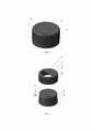
на фиг. 1 – общий вид укупорочного устройства с контролем вскрытия до первого открывания;in fig. 1 is a general view of the closure with tamper evident before the first opening;
на фиг. 2 – укупорочное устройство в разобранном состоянии (общий вид);in fig. 2 - disassembled closure device (general view);
на фиг. 3 – укупорочное устройство в разобранном состоянии (вид снизу);in fig. 3 - disassembled closure device (bottom view);
на фиг. 4 – часть корпуса укупорочного устройства;in fig. 4 - part of the body of the closure device;
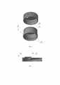
на фиг. 5 – укупорочное устройство со срезанным индикатором вскрытия и открытым дозирующим отверстием (положение «Дозирования»);in fig. 5 - a capping device with a cut-off tamper evident indicator and an open dispensing hole (“Dispensing” position);
на фиг. 6 – укупорочное устройство со срезанным индикатором вскрытия и закрытым дозирующим отверстием (положение «Закрыто»).in fig. 6 - a closure device with a cut-off tamper evident indicator and a closed dispensing opening (“Closed” position).
Позициями на чертежах обозначены:Positions in the drawings indicate:
1. корпус;1. body;
2. поворотная крышка;2. swivel cover;
3. кольцевой выступ;3. annular ledge;
4. боковая поверхность корпуса;4. side surface of the case;
5. индикатор вскрытия;5. tamper indicator;
6. окно;6. window;
7. участок, выполненный заостренным в форме заточенной грани ножа;7. a section made sharpened in the form of a sharpened edge of a knife;
8. элемент крепления (резьба);8. fastening element (thread);
9. кольцевой паз;9. annular groove;
10. указатель направления поворота крышки (стрелка);10. indicator of the direction of rotation of the cover (arrow);
11. вертикальные выступы (рифления);11. vertical projections (corrugations);
12. фиксирующий выступ;12. fixing protrusion;
13. дозирующее отверстие;13. dispensing hole;
14. вертикальный паз;14. vertical groove;
15. выступ;15. ledge;
16. стенка индикатора вскрытия в форме полукольца;16. the wall of the tamper evident indicator is in the form of a half ring;
17. радиальная боковая стенка индикатора вскрытия;17. radial side wall of the tamper indicator;
18. верхняя полукруглая часть индикатора вскрытия.18. Upper semicircular part of the tamper indicator.
Укупорочное устройство с контролем вскрытия имеет двухкомпонентную, соосную структуру (фиг. 1), состоящую из корпуса 1 и поворотной крышки 2, выполненной с возможностью поворота относительно корпуса 1.The tamper-evident closure has a two-component, coaxial structure (Fig. 1), consisting of a
Корпус 1 имеет форму полого цилиндра с одним верхним основанием и боковой поверхностью 4. В нижней части боковой поверхности 4 выполнен кольцевой выступ 3 прямоугольного сечения, служащий упором для поворотной крышки 2. На верхнем основании корпуса 1 расположен индикатор вскрытия 5, представляющий собой полый выступ, имеющий боковые стенки разной толщины, одна из которых в форме полукольца, а вторая – радиальная (фиг. 2-4). Стенка индикатора вскрытия в форме полукольца 16 имеет толщину 0,16 мм, радиальная боковая стенка индикатора вскрытия 17 имеет толщину 0,08 мм, а верхняя полукруглая часть индикатора вскрытия 18 имеет толщину 0,8 мм. На боковой поверхности 4 корпуса 1 расположены вертикальные пазы 14 круглого сечения.The
Поворотная крышка 2 имеет полукруглое окно 6, соответствующее по форме выступу индикатора вскрытия 5, но большее по размеру. Это обеспечивает возможность размещения в окне 6 индикатора 5, но препятствует осевому вращению поворотной крышки 2 относительно корпуса 1 при хранении и транспортировке.The hinged
Радиальная часть окна 6 имеет участок 7, выполненный заостренным под углом 30˚ в форме заточенной грани ножа, расположенной под углом 10˚ к радиальной боковой стенке индикатора вскрытия.The radial part of the
На внутренней стороне боковой поверхности 4 корпуса 1 выполнен элемент крепления 8 в виде резьбы для присоединения к горловине контейнера.On the inner side of the
В верхней части боковой поверхностью 4 корпуса 1 выполнен кольцевой паз 9, предназначенный для фиксации поворотной крышки 2. Направление поворота показано рельефно выступающей стрелкой 10, выполненной сверху на наружной части поворотной крышки 2. Поворотная крышка 2 имеет цилиндрическую форму, повторяющую форму боковой поверхности 4 корпуса 1.An
На внешней боковой поверхности крышки 2 на одинаковом расстоянии друг от друга расположен ряд одинаковых вертикальных выступов (рифлений) 11 в виде части цилиндра, предназначенных для исключения проскальзывания в руках. На её внутренней боковой поверхности расположен выступ 15, обеспечивающий сопряжение с корпусом 1 посредством кольцевого паза 9.On the outer side surface of the
Укупорочное устройство работает следующим образом.The capping device works as follows.
Потребитель берет в руки контейнер с крышкой и поворачивает крышку 2 по направлению, показанному стрелкой 10. Заостренная грань участка 7 начинает подрезать радиальную боковую стенку индикатора вскрытия 17. Благодаря тому, что заостренная грань участка 7 расположена под углом 10˚ к радиальной боковой стенке индикатора вскрытия 17, срез имеет режущий, а не рубящий характер вскрытия. Дальнейшее отделение (подрезание) индикатора вскрытия 5 от корпуса 1 происходит с меньшими усилиями. При дальнейшем вращении поворотной крышки 2 участок 7, имеющий угол заточки 30˚, начинает подрезать стенку индикатора вскрытия в форме полукольца 16, приподнимает верхнюю полукруглую часть индикатора вскрытия 18 и полностью срезает его, образуя при этом дозирующее отверстие 13 (фиг. 5).The consumer picks up the container with the lid and turns the
Толщина верхней полукруглой части индикатора вскрытия 18 подобрана таким образом, чтобы создать дополнительное напряжение в месте подрезания стенки индикатора вскрытия в форме полукольца 16, облегчив усилие разрезания, несмотря на более толстую стенку.The thickness of the upper semicircular part of the
Участок 7 гарантированно надрезает радиальную боковую стенку индикатора вскрытия 17 даже при использовании мягких материалов при производстве поворотной крышки 2.
Дозирующее отверстие 13 открывается, герметизация нарушается. Таким образом, корпус 1 утратил признак визуальной целостности конструкции и приобрел признак дозатора, содержимое контейнера можно использовать.The dispensing
Поворотная крышка 2 получила возможность осевого проворачивания относительно корпуса 1.The
В этом состоянии поворотная крышка 2 имеет два положения фиксации относительно корпуса 1.In this state, the
Первое положение «Дозирования» (фиг. 5), когда окно 6 в крышке 2 и вновь образованное дозирующее отверстие 13 в корпусе 1 совмещены.The first "Dispensing" position (Fig. 5), when the
Второе положение «Закрыто» (фиг. 6), когда окно 6 в поворотной крышке 2 совмещено с «глухой» частью корпуса 1.The second position is "Closed" (Fig. 6), when the
Фиксация положений обеспечивается при совмещении фиксирующих выступов 12, расположенных на внутренней боковой поверхности поворотной крышки 2 с вертикальными пазами 14, расположенными на боковой поверхности 4 корпуса 1.Fixation of positions is ensured by aligning the fixing
Для того, чтобы закрыть укупорочное устройство, нужно повернуть поворотную крышку 2 в положение «Закрыто» - окно 6 в крышке 2 будет совмещено с «глухой» частью корпуса 1 (фиг. 6).In order to close the closure device, you need to turn the
Для того, чтобы открыть дозирующее отверстие 13, поворотную крышку 2 переводят в положение «Дозирования». В этом положении окно 6 в крышке 2 и дозирующее отверстие 13 в корпусе 1 совмещены.In order to open the dispensing
Таким образом, заявляемое изобретение за счет монолитной формы корпуса и особой конструкции индикатора вскрытия и поворотной крышки позволяет обеспечить полную герметичность содержимого контейнера при хранении и транспортировке, а также позволяет визуально контролировать первое вскрытие упаковки и гарантирует надежную защиту продукции от подделок.Thus, the claimed invention, due to the monolithic shape of the body and the special design of the tamper evident indicator and the rotary lid, allows to ensure complete tightness of the contents of the container during storage and transportation, and also allows visual control of the first opening of the package and guarantees reliable protection of products from counterfeiting.
Также заявляемое изобретение позволяет расширить арсенал существующих укупорочных устройств с контролем вскрытия.Also, the claimed invention allows you to expand the arsenal of existing closures with tamper evident.
Claims (4)
Translated fromRussianPriority Applications (1)
| Application Number | Priority Date | Filing Date | Title |
|---|---|---|---|
| RU2021103988ARU2760759C1 (en) | 2021-02-17 | 2021-02-17 | Tamper evident sealing device |
Applications Claiming Priority (1)
| Application Number | Priority Date | Filing Date | Title |
|---|---|---|---|
| RU2021103988ARU2760759C1 (en) | 2021-02-17 | 2021-02-17 | Tamper evident sealing device |
Publications (1)
| Publication Number | Publication Date |
|---|---|
| RU2760759C1true RU2760759C1 (en) | 2021-11-30 |
Family
ID=79174166
Family Applications (1)
| Application Number | Title | Priority Date | Filing Date |
|---|---|---|---|
| RU2021103988ARU2760759C1 (en) | 2021-02-17 | 2021-02-17 | Tamper evident sealing device |
Country Status (1)
| Country | Link |
|---|---|
| RU (1) | RU2760759C1 (en) |
Citations (9)
| Publication number | Priority date | Publication date | Assignee | Title |
|---|---|---|---|---|
| US3073468A (en)* | 1961-09-15 | 1963-01-15 | Rap Inc | Tamper-proof closure cap |
| US4801028A (en)* | 1986-10-03 | 1989-01-31 | Spectra King Precision Engineers Limited | Closure device for a container having a cylindrical opening |
| GB2240095A (en)* | 1990-01-18 | 1991-07-24 | Robinson & Sons Ltd | Tamper evident package |
| US5884788A (en)* | 1997-12-17 | 1999-03-23 | Wilde; Sheldon L. | Tamper-indicating closure |
| EP1413526A1 (en)* | 2002-10-22 | 2004-04-28 | Heinlein Plastik-Technik GmbH | Cap-like turn closure for containers and container comprising such a closure |
| WO2006099854A2 (en)* | 2005-03-21 | 2006-09-28 | Lamberty Frank C | Closure for making a prior opening of the closure visible |
| RU77850U1 (en)* | 2008-06-16 | 2008-11-10 | Закрытое акционерное общество "Завод тарных изделий" | COVER WITH CONTROL RING FOR CUPS OF POLYMER CONTAINERS |
| RU2466071C2 (en)* | 2007-08-30 | 2012-11-10 | Берикап Гмбх Унд Ко. Кг | Threaded cap with opening control tape |
| RU2662669C2 (en)* | 2013-08-29 | 2018-07-26 | Сакми Кооператива Мекканичи Имола Сочьета' Кооператива | Protective cover for containers |
- 2021
- 2021-02-17RURU2021103988Apatent/RU2760759C1/enactive
Patent Citations (9)
| Publication number | Priority date | Publication date | Assignee | Title |
|---|---|---|---|---|
| US3073468A (en)* | 1961-09-15 | 1963-01-15 | Rap Inc | Tamper-proof closure cap |
| US4801028A (en)* | 1986-10-03 | 1989-01-31 | Spectra King Precision Engineers Limited | Closure device for a container having a cylindrical opening |
| GB2240095A (en)* | 1990-01-18 | 1991-07-24 | Robinson & Sons Ltd | Tamper evident package |
| US5884788A (en)* | 1997-12-17 | 1999-03-23 | Wilde; Sheldon L. | Tamper-indicating closure |
| EP1413526A1 (en)* | 2002-10-22 | 2004-04-28 | Heinlein Plastik-Technik GmbH | Cap-like turn closure for containers and container comprising such a closure |
| WO2006099854A2 (en)* | 2005-03-21 | 2006-09-28 | Lamberty Frank C | Closure for making a prior opening of the closure visible |
| RU2466071C2 (en)* | 2007-08-30 | 2012-11-10 | Берикап Гмбх Унд Ко. Кг | Threaded cap with opening control tape |
| RU77850U1 (en)* | 2008-06-16 | 2008-11-10 | Закрытое акционерное общество "Завод тарных изделий" | COVER WITH CONTROL RING FOR CUPS OF POLYMER CONTAINERS |
| RU2662669C2 (en)* | 2013-08-29 | 2018-07-26 | Сакми Кооператива Мекканичи Имола Сочьета' Кооператива | Protective cover for containers |
Similar Documents
| Publication | Publication Date | Title |
|---|---|---|
| US5020682A (en) | Closure system | |
| RU2388673C2 (en) | Plug with indicator of unauthorised opening | |
| RU2437815C1 (en) | Vessel cover | |
| CA2855487C (en) | Tamper evident closure | |
| US5482176A (en) | Membrane piercing closure and spout assembly | |
| US5167338A (en) | Shake and pour end closure with stay open lid | |
| AU2004286926B2 (en) | Twist-open closure having inclined frangible membrane | |
| US4588098A (en) | Closures for containers having tampering indicating means | |
| RU2612853C2 (en) | Tamper-evident closure | |
| EP2244955A1 (en) | Twist open closure having inclined frangible membrane | |
| RU2683359C2 (en) | Tamper-evident closure | |
| KR20160022880A (en) | A cap with a cutting element | |
| US6431380B1 (en) | Child-resistant flip top closure | |
| US4276988A (en) | Tamper-proof closure | |
| RU2760759C1 (en) | Tamper evident sealing device | |
| CN107709180B (en) | Assembly comprising a threaded cap portion and a neck portion for indicating tampering with a container | |
| GB2222399A (en) | A closure for a container | |
| CN209796259U (en) | Bottle cap | |
| JP4342839B2 (en) | Easy-open container lid | |
| PL201577B1 (en) | Threaded packaging with a 'click' function | |
| AU712054B2 (en) | Piercing container cap | |
| PL226209B1 (en) | Safety screw cap with security element, preferably for the pharmaceutical industry | |
| RU2825036C1 (en) | Tamper-proof container | |
| RU67554U1 (en) | BOTTLE SAFETY CAP | |
| EP3381831A1 (en) | Tamper-indicating assembly of threaded closure and neck for containers |