RU2759664C1 - Method for manufacturing flexible fibre-optic tape and tape - Google Patents
Method for manufacturing flexible fibre-optic tape and tapeDownload PDFInfo
- Publication number
- RU2759664C1 RU2759664C1RU2020127174ARU2020127174ARU2759664C1RU 2759664 C1RU2759664 C1RU 2759664C1RU 2020127174 ARU2020127174 ARU 2020127174ARU 2020127174 ARU2020127174 ARU 2020127174ARU 2759664 C1RU2759664 C1RU 2759664C1
- Authority
- RU
- Russia
- Prior art keywords
- optical fibers
- tape
- curable resin
- assembly
- outer layer
- Prior art date
Links
Images


Classifications
- G—PHYSICS
- G02—OPTICS
- G02B—OPTICAL ELEMENTS, SYSTEMS OR APPARATUS
- G02B6/00—Light guides; Structural details of arrangements comprising light guides and other optical elements, e.g. couplings
- G02B6/44—Mechanical structures for providing tensile strength and external protection for fibres, e.g. optical transmission cables
- G02B6/4479—Manufacturing methods of optical cables
- G02B6/448—Ribbon cables
- C—CHEMISTRY; METALLURGY
- C03—GLASS; MINERAL OR SLAG WOOL
- C03C—CHEMICAL COMPOSITION OF GLASSES, GLAZES OR VITREOUS ENAMELS; SURFACE TREATMENT OF GLASS; SURFACE TREATMENT OF FIBRES OR FILAMENTS MADE FROM GLASS, MINERALS OR SLAGS; JOINING GLASS TO GLASS OR OTHER MATERIALS
- C03C25/00—Surface treatment of fibres or filaments made from glass, minerals or slags
- C03C25/10—Coating
- C03C25/104—Coating to obtain optical fibres
- C03C25/1065—Multiple coatings
- G—PHYSICS
- G02—OPTICS
- G02B—OPTICAL ELEMENTS, SYSTEMS OR APPARATUS
- G02B6/00—Light guides; Structural details of arrangements comprising light guides and other optical elements, e.g. couplings
- G02B6/02—Optical fibres with cladding with or without a coating
- G02B6/02033—Core or cladding made from organic material, e.g. polymeric material
- G—PHYSICS
- G02—OPTICS
- G02B—OPTICAL ELEMENTS, SYSTEMS OR APPARATUS
- G02B6/00—Light guides; Structural details of arrangements comprising light guides and other optical elements, e.g. couplings
- G02B6/44—Mechanical structures for providing tensile strength and external protection for fibres, e.g. optical transmission cables
- G02B6/4401—Optical cables
- G02B6/4403—Optical cables with ribbon structure
- G02B6/4404—Multi-podded
- G—PHYSICS
- G02—OPTICS
- G02B—OPTICAL ELEMENTS, SYSTEMS OR APPARATUS
- G02B6/00—Light guides; Structural details of arrangements comprising light guides and other optical elements, e.g. couplings
- G02B6/44—Mechanical structures for providing tensile strength and external protection for fibres, e.g. optical transmission cables
- G02B6/4401—Optical cables
- G02B6/441—Optical cables built up from sub-bundles
- G—PHYSICS
- G02—OPTICS
- G02B—OPTICAL ELEMENTS, SYSTEMS OR APPARATUS
- G02B6/00—Light guides; Structural details of arrangements comprising light guides and other optical elements, e.g. couplings
- G02B6/44—Mechanical structures for providing tensile strength and external protection for fibres, e.g. optical transmission cables
- G02B6/4401—Optical cables
- G02B6/4429—Means specially adapted for strengthening or protecting the cables
- G—PHYSICS
- G02—OPTICS
- G02B—OPTICAL ELEMENTS, SYSTEMS OR APPARATUS
- G02B6/00—Light guides; Structural details of arrangements comprising light guides and other optical elements, e.g. couplings
- G02B6/44—Mechanical structures for providing tensile strength and external protection for fibres, e.g. optical transmission cables
- G02B6/4479—Manufacturing methods of optical cables
- G02B6/4486—Protective covering
- G02B6/4488—Protective covering using metallic tubes
Landscapes
- Physics & Mathematics (AREA)
- General Physics & Mathematics (AREA)
- Optics & Photonics (AREA)
- Engineering & Computer Science (AREA)
- Manufacturing & Machinery (AREA)
- Chemical & Material Sciences (AREA)
- Life Sciences & Earth Sciences (AREA)
- Chemical Kinetics & Catalysis (AREA)
- General Life Sciences & Earth Sciences (AREA)
- General Chemical & Material Sciences (AREA)
- Geochemistry & Mineralogy (AREA)
- Materials Engineering (AREA)
- Organic Chemistry (AREA)
- Optical Fibers, Optical Fiber Cores, And Optical Fiber Bundles (AREA)
- Surface Treatment Of Glass Fibres Or Filaments (AREA)
- Mechanical Coupling Of Light Guides (AREA)
Abstract
Description
Translated fromRussianОБЛАСТЬ ТЕХНИКИ, К КОТОРОЙ ОТНОСИТСЯ ИЗОБРЕТЕНИЕTECHNICAL FIELD OF THE INVENTION
Настоящее изобретение относится к способу изготовления волоконно-оптической ленты и к волоконно-оптической ленте.The present invention relates to a method for manufacturing an optical fiber tape and to an optical fiber tape.
УРОВЕНЬ ТЕХНИКИLEVEL OF TECHNOLOGY
Количество данных, передаваемых по волоконно-оптическим кабелям, непрерывно возрастает. Например, вследствие увеличения объема вычислений в облачной среде это возрастание особенно заметно в центрах данных во всем мире, в которые все данные передаются в течение ограниченного промежутка времени. Это является причиной растущих потребностей в оптических кабелях с большим количеством волокон и высокой плотностью волокон. Кроме того, неизменно существует тенденция к снижению расходов на монтаж кабельных сетей доступа, что делает важным уменьшение диаметра и массы оптического кабеля. В случае уменьшения диаметра и массы оптического кабеля можно будет использовать существующее оборудование, такое как подземные каналы, при этом будут снижаться затраты на монтажные работы. Дополнительное требование заключается в том, что для сокращения рабочего времени при соединении кабелей должно производиться массовое сращивание оптических волокон сплавлением.The amount of data transmitted over fiber optic cables is constantly increasing. For example, due to the increase in computing in the cloud, this increase is especially noticeable in data centers around the world, to which all data is transferred within a limited period of time. This is the reason for the growing demand for high fiber count and high fiber density optical cables. In addition, there is invariably a tendency to reduce the installation costs of cable access networks, which makes it important to reduce the diameter and weight of optical cable. If the diameter and weight of the optical cable is reduced, it will be possible to use existing equipment, such as underground channels, while reducing the cost of installation work. An additional requirement is that mass fusion splices of optical fibers should be performed to reduce the working time when connecting cables.
Это означает, что имеются несколько предъявляемых требований, возможно противоречивых, с одной стороны, это уменьшение диаметра оптического кабеля, а с другой стороны, повышение плотности оптических волокон. Это является серьезной проблемой для производителей оптических волокон.This means that there are several requirements, possibly contradictory, on the one hand, this is a decrease in the diameter of the optical cable, and on the other hand, an increase in the density of optical fibers. This is a major concern for optical fiber manufacturers.
Для облегчения прокладки используют волоконно-оптические ленты, которые могут быть соединены массовым сращиванием сплавлением для образования многочисленных соединений оптических волокон и при этом с повышенной гибкостью.For ease of installation, fiber optic tapes are used that can be mass-fusion spliced to form multiple optical fiber splices with increased flexibility.
Однако стандартные волоконно-оптические ленты имеют недостаток, заключающийся в жесткости, вызванной тем, что вокруг сборки оптических волокон нанесен слой смолы для удержания оптических волокон параллельными в плоскости. Эта жесткость ограничивает возможность повышения плотности волокон в волоконно-оптических кабелях.However, conventional fiber optic ribbons have the disadvantage of stiffness due to the resin layer being applied around the optical fiber assembly to keep the optical fibers parallel in a plane. This stiffness limits the ability to increase the density of fibers in fiber optic cables.
В документе JP 2011221199 предложена концепция получения более гибкой волоконно-оптической ленты путем нанесения матричного связующего материала по синусоидальной линии на одну сторону сборки параллельных прилегающих оптических волокон.JP 2011221199 proposes a concept for a more flexible fiber optic ribbon by applying a matrix binder in a sinusoidal line to one side of an array of parallel adjacent optical fibers.
СУЩНОСТЬ ИЗОБРЕТЕНИЯSUMMARY OF THE INVENTION
Задача настоящего изобретения заключается в создании оптической ленты и способа изготовления оптической ленты, имеющей повышенную гибкость и позволяющей сворачивать или складывать оптические волокна в направлении ширины ленты и в то же время имеющей высокую прочность. Другая задача настоящего изобретения заключается в создании оптической ленты, волокна которой можно соединять массовым сращиванием сплавлением для образования многочисленных соединений оптических волокон. Дальнейшая задача настоящего изобретения заключается в создании волоконно-оптической ленты, содержащей группы из самое большее трех оптических волокон, инкапсулированных матричным материалом, от которой отдельные оптические волокна можно отделять без повреждения прилегающих оптических волокон.An object of the present invention is to provide an optical tape and a method for manufacturing an optical tape having increased flexibility and allowing the folding or folding of optical fibers in the direction of the width of the tape and at the same time having high strength. Another object of the present invention is to provide an optical tape whose fibers can be mass-fusion spliced to form multiple optical fiber splices. A further object of the present invention is to provide an optical fiber tape comprising groups of at most three optical fibers, encapsulated by a matrix material, from which individual optical fibers can be separated without damaging adjacent optical fibers.
Согласно первому аспекту одна или несколько из этих задач решаются способом изготовления волоконно-оптической ленты, содержащимAccording to a first aspect, one or more of these objects are achieved by a method for manufacturing an optical fiber tape comprising
- подачу множества оптических волокон для подготовки продольной сборки оптических волокон, при этом множество оптических волокон располагают параллельно и с прилеганием друг к другу, при этом каждое из множества оптических волокон содержит от центра к периферии стеклянную сердцевину, стеклянную оболочку, первичное покрытие, вторичное покрытие и внешний слой, образованный из частично отвержденной первой отверждаемой смолы;supplying a plurality of optical fibers to prepare a longitudinal optical fiber assembly, wherein the plurality of optical fibers are arranged in parallel and adjacent to each other, each of the plurality of optical fibers comprising a glass core, a glass cladding, a primary coating, a secondary coating, and an outer layer formed of a partially cured first curable resin;
- нанесение второй отверждаемой смолы из раздатчика на поверхность сборки, при этом вторая отверждаемая смолы образует множество последовательных удлиненных прямолинейных валиков, выполненных с возможностью образования соединений между двумя прилегающими оптическими волокнами из множества оптических волокон; и- applying a second curable resin from a dispenser to a surface of the assembly, the second curable resin forming a plurality of successive elongated rectilinear rolls configured to form connections between two adjacent optical fibers from the plurality of optical fibers; and
- пропускание сборки с валиками из второй отверждаемой смолы, нанесенной на нее, через станцию отверждения для отверждения второй отверждаемой смолы и для завершения отверждения частично отвержденной первой отверждаемой смолы внешнего слоя каждого оптического волокна, чтобы образовать соединения. Валики соединяют внешние слои оптического волокна друг с другом.passing the assembly with rollers of the second curable resin applied thereto through the curing station to cure the second curable resin and to complete curing of the partially cured first curable resin of the outer layer of each optical fiber to form bonds. The rollers connect the outer layers of the optical fiber to each other.
Согласно второму аспекту одна или несколько из этих задач решаются созданием волоконно-оптической ленты, содержащей:In a second aspect, one or more of these objectives are achieved by providing an optical fiber tape comprising:
- множество прилегающих оптических волокон, продолжающихся в продольном направлении и расположенных параллельно, образующих сборку оптических волокон;- a plurality of adjacent optical fibers, extending in the longitudinal direction and located in parallel, forming an optical fiber assembly;
- множество последовательных удлиненных прямолинейных валиков из второй отвержденной смолы, расположенных по длине сборки; каждый из множества валиков выполнен с возможностью образования удлиненного соединения между двумя прилегающими оптическими волокнами из множества оптических волокон;- a plurality of successive elongated rectilinear beads of the second cured resin located along the length of the assembly; each of the plurality of rollers is configured to form an elongated connection between two adjacent optical fibers from the plurality of optical fibers;
- в которой каждое из множества оптических волокон содержит от центра к периферии стеклянную сердцевину, стеклянную оболочку, первичное покрытие, вторичное покрытие и внешний слой, образованный из первой отвержденной смолы;- in which each of the plurality of optical fibers contains from the center to the periphery a glass core, a glass cladding, a primary coating, a secondary coating and an outer layer formed from the first cured resin;
- в которой вторая отвержденная смола каждого удлиненного соединения химически связана с соответствующей первой отвержденной смолой двух прилегающих оптических волокон.- in which the second cured resin of each elongated joint is chemically bonded to the corresponding first cured resin of the two adjacent optical fibers.
Соответствующие варианты осуществления ленты, раскрытые ниже, также применимы к способу согласно настоящему изобретению и наоборот.Corresponding belt embodiments disclosed below are also applicable to the method of the present invention and vice versa.
Таким образом, волоконно-оптическая лента согласно настоящему изобретению имеет многочисленные оптические волокна, расположенные параллельно, которые соединены с другими оптическими волокнами посредством валиков из отвержденной смолы. Соединение создают отверждением отверждаемой смолы валиков на частично отвержденной первой отверждаемой смоле внешнего слоя каждого из оптических волокон; этим создают связь или соединение между валиками и внешним слоем, вследствие чего повышается прочность соединения между валиком и внешним слоем.Thus, the optical fiber tape of the present invention has multiple optical fibers arranged in parallel, which are connected to other optical fibers by means of cured resin rollers. The bonding is created by curing the curable resin of the rollers on the partially cured first curable resin of the outer layer of each of the optical fibers; this creates a bond or bond between the rollers and the outer layer, thereby increasing the bond strength between the roller and the outer layer.
При удалении/отделении оптического волокна от ленты предпочтительно, чтобы точка повреждения/разрыва находилась в самом валике, или во внешнем слое, или между внешним слоем и вторичным покрытием. Для поддержания целостности оптического волокна во время отделения нежелательно нахождение точки повреждения/разрыва во вторичном покрытии или на границе с первичным покрытием, поскольку при этом оптическое волокно повреждается. В настоящем изобретении отверждение внешнего слоя относительно валика приводит к направлению точки повреждения из оптического волокна к границе между внешним слоем и вторичным покрытием или во внешний слой. Этот внешний слой действует как слой освобождения. Изобретатели настоящего изобретения обнаружили, что сочетанием таких признаков, как наличие внешнего слоя и наличие связи с валиком, обеспечивается точка повреждения, при которой оптические волокна не повреждаются и отсутствует влияние на целостность их. Хотя внешний слой является частью оптического волокна, его можно (частично) удалять без разрушения структурных частей оптического волокна, которыми являются стеклянная сердцевина, стеклянная оболочка, первичное покрытие и вторичное покрытие.When removing / separating the optical fiber from the tape, it is preferable that the point of damage / break is in the roller itself, or in the outer layer, or between the outer layer and the secondary coating. In order to maintain the integrity of the optical fiber during separation, it is undesirable to locate the point of damage / breakage in the secondary coating or at the interface with the primary coating, since this will damage the optical fiber. In the present invention, the curing of the outer layer relative to the bead leads to the direction of the point of damage from the optical fiber to the interface between the outer layer and the secondary coating or to the outer layer. This outer layer acts as a release layer. The inventors of the present invention have found that the combination of features such as the presence of an outer layer and a connection with the bead provides a point of failure at which the optical fibers are not damaged and there is no effect on their integrity. Although the outer layer is part of the optical fiber, it can be (partially) removed without destroying the structural parts of the optical fiber, which are the glass core, glass cladding, Primary Coating, and Secondary Coating.
ОПИСАНИЕ ДЕФИНИЦИЙDESCRIPTION OF DEFINITIONS
Приведенные ниже дефиниции (определения, используемых терминов и формулировок) используются в настоящем описании и формуле изобретения для определения излагаемого объекта изобретения. Другие термины, не описанные ниже, имеют смысловое содержание, общепринятое в данной области техники.The following definitions (definitions, terms and formulations used) are used in the present description and the claims to define the stated subject matter of the invention. Other terms not described below have the connotations generally accepted in the art.
Термин «сборка оптических волокон», используемый в настоящем описании, означает несвязанную структуру из множества параллельных прилегающих оптических волокон без какого-либо соединения между любыми волокнами; сборка имеет ширину (W) и имеет углубления или канавки между прилегающими оптическими волокнами.The term "optical fiber assembly" as used herein means an unbonded structure of a plurality of parallel adjacent optical fibers without any connection between any fibers; the assembly has a width (W) and has depressions or grooves between adjacent optical fibers.
Понятие «ширина (W) сборки» или «ширина (W)», используемое в настоящем описании, означает, что сборка образована из некоторого количества (N) оптических волокон, каждое из которых имеет диаметр (D) и длину (L); при этом сборка имеет ширину (W; W=D×N).The term "width (W) of the assembly" or "width (W)" used in the present description means that the assembly is formed from a number (N) of optical fibers, each of which has a diameter (D) and a length (L); the assembly has a width (W; W = D × N).
Термин «валик», используемый в настоящем описании, означает валик из второй отверждаемой смолы, который соединяет два прилегающих оптических волокна на протяжении длины (l) соединения. Следует отметить, что, если два (или большее количество) последующих валиков уложены друг за другом в одну и ту же канавку, сообщающуюся с одними и теми же двумя прилегающими оптическими волокнами, эти два (или большее количество) валиков считаются совместно образующими соединение длиной (l), равной сумме протяженностей таких последующих валиков.The term "bead" as used herein means a bead of a second curable resin that connects two adjacent optical fibers along the length (l) of the connection. It should be noted that if two (or more) subsequent rollers are stacked one after the other in the same groove communicating with the same two adjacent optical fibers, these two (or more) rollers are considered to jointly form a joint of length ( l) equal to the sum of the lengths of such subsequent rolls.
Термин «связующий материал», используемый в настоящем описании, означает материал, из которого образуют соединение. Он представляет собой вторую отвержденную смолу или еще не отвержденную вторую отверждаемую смолу.The term "binder" as used herein means the material from which the compound is formed. It is a second cured resin or an as yet uncured second cured resin.
Термин «материал внешнего слоя», используемый в настоящем описании, означает материал, из которого образуют внешний слой, и он представляет собой первую смолу, которая в зависимости от стадии процесса является отверждаемой, частично отвержденной или отвержденной.The term "outer layer material" as used herein means the material from which the outer layer is formed and is the first resin which, depending on the process step, is curable, partially cured or cured.
Термин «химически связанный», используемый в настоящем описании, означает наличие химических ковалентных связей, которые создаются при одновременном отверждении второй отверждаемой смолы и частичном отверждении первой отверждаемой смолы. Каждая из этих смол содержит множество химически активных групп, которые образуют поперечные связи (химические связи) в течение отверждения; вследствие одновременного отверждения на границе валиков и внешнего слоя будут создаваться химические ковалентные связи между химически активными группами, присутствующими во второй отверждаемой смоле соединений/валиков и в частично отвержденной первой отверждаемой смоле внешнего слоя.The term "chemically bonded" as used herein means the presence of chemical covalent bonds that are created by the simultaneous curing of the second curable resin and partial curing of the first curable resin. Each of these resins contains many reactive groups that cross-link (chemical bonds) during cure; due to the simultaneous curing at the interface of the beads and the outer layer, chemical covalent bonds will be created between the reactive groups present in the second curable resin of the joints / beads and in the partially cured first curable resin of the outer layer.
Термин «ступенчатый рельеф», используемый в настоящем описании, означает рельеф, образованный последовательностью валиков на протяжении множества оптических волокон, при этом валики из последовательности валиков каждый раз разнесены на интервале одного оптического волокна в направлении ширины. Это означает, что шагом ступенчатого рельефа является одно оптическое волокно. Поэтому в случае, когда сборка должна быть образована некоторым количеством N оптических волокон, отдельный ступенчатый рельеф образуют с помощью последовательности (N-1) валиков.The term "stepped relief" as used herein means a relief formed by a series of rolls along a plurality of optical fibers, the rolls of the sequence of rolls being spaced apart by one optical fiber in the width direction each time. This means that the step of the stepped relief is one optical fiber. Therefore, in the case where the assembly is to be formed by a number N of optical fibers, a separate stepped relief is formed by a sequence of (N-1) beads.
Термин «зигзагообразная структура», используемый в настоящем описании, означает структуру, повторяющую траекторию треугольной волны. Зигзагообразную структуру в настоящей заявке получают проведением линии через средние точки последовательных валиков из последовательных ступенчатых рельефов.The term "zigzag structure" as used herein means a structure that follows the path of a triangular wave. The zigzag structure in this application is obtained by drawing a line through the midpoints of successive rolls from successive stepped reliefs.
Термин «пилообразная структура», используемый в настоящем описании, означает структуру, повторяющую траекторию пилообразной волны. Пилообразную структуру в настоящей заявке получают проведением линии через средние точки последовательных валиков из последовательных ступенчатых рельефов.The term "sawtooth structure" as used in the present description means a structure that follows the path of the sawtooth wave. The sawtooth structure in this application is obtained by drawing a line through the midpoints of successive rolls from successive stepped reliefs.
Термин «шаг (Р)», используемый в настоящем описании, определен как длина, равная периодичности ступенчатого рельефа в одном и том же направлении ширины.The term "pitch (P)" as used herein is defined as a length equal to the periodicity of a stepped relief in the same direction of width.
КРАТКОЕ ОПИСАНИЕ ЧЕРТЕЖЕЙBRIEF DESCRIPTION OF DRAWINGS
Ниже настоящее изобретение описывается с обращением к сопровождающим схематичным чертежам, на которых показаны варианты осуществления настоящего изобретения и на которых одинаковыми позициями обозначены одни и те же или подобные элементы. На чертежах:The present invention is described below with reference to the accompanying schematic drawings, which show embodiments of the present invention and in which like reference numbers refer to the same or similar elements. In the drawings:
фиг. 1 - трехмерный вид сборки оптических волокон (не являющейся частью изобретению);fig. 1 is a three-dimensional view of an optical fiber assembly (not part of the invention);
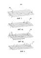
фиг. 2а - трехмерный вид волоконно-оптической ленты согласно варианту осуществления изобретения, имеющей прерывистую/прерывную зигзагообразную структуру;fig. 2a is a three-dimensional view of an optical fiber ribbon according to an embodiment of the invention having a discontinuous / discontinuous zigzag structure;
фиг. 2b - вид волоконно-оптической ленты согласно варианту осуществления изобретения, имеющей прерывистую/прерывную зигзагообразную структуру с другой длиной соединения, чем в варианте осуществления из фиг. 2а;fig. 2b is a view of a fiber optic ribbon according to an embodiment of the invention having a discontinuous / discontinuous zigzag structure with a different connection length than the embodiment of FIG. 2a;
фиг. 3 - трехмерный вид волоконно-оптической ленты согласно варианту осуществления изобретения, имеющей непрерывную зигзагообразную структуру;fig. 3 is a three-dimensional view of an optical fiber ribbon according to an embodiment of the invention having a continuous zigzag structure;
фиг. 4а - трехмерный вид волоконно-оптической ленты согласно варианту осуществления изобретения, имеющей прерывистую/прерывную пилообразную структуру;fig. 4a is a three-dimensional view of an optical fiber tape according to an embodiment of the invention having a discontinuous / discontinuous sawtooth structure;
фиг. 4b - вид волоконно-оптической ленты из фиг. 4а с показом аппроксимирующей пилообразной линии и шага;fig. 4b is a view of the fiber optic tape of FIG. 4a showing an approximating sawtooth line and pitch;
фиг. 5 - трехмерный вид волоконно-оптической ленты согласно варианту осуществления, имеющей частично непрерывную пилообразную структуру;fig. 5 is a three-dimensional view of an optical fiber ribbon according to an embodiment having a partially continuous sawtooth structure;
фиг. 6 - трехмерный вид волоконно-оптической ленты согласно варианту осуществления, имеющей непрерывную пилообразную структуру;fig. 6 is a three-dimensional view of an optical fiber tape according to an embodiment having a continuous sawtooth structure;
фиг. 7 - схематичное изображение возможной технологической линии для изготовления волоконно-оптической ленты, имеющей шесть оптических волокон;fig. 7 is a schematic illustration of a possible production line for making an optical fiber tape having six optical fibers;
фиг. 8 - перспективный вид волоконно-оптической ленты, имеющей зигзагообразную структуру;fig. 8 is a perspective view of a fiber optic tape having a zigzag structure;
фиг. 9 - перспективный вид волоконно-оптической ленты, имеющей пилообразную структуру;fig. 9 is a perspective view of a fiber optic tape having a sawtooth structure;
фиг. 10 - вид сверху ленты согласно варианту осуществления настоящего изобретения; иfig. 10 is a top view of a tape according to an embodiment of the present invention; and
фиг. 11 - поперечное сечение секции волоконно-оптического кабеля, изготовленного с использованием 24 волоконно-оптических лент, каждая из которых имеет 12 оптических волокон.fig. 11 is a cross-sectional view of a section of a fiber optic cable made using 24 fiber optic ribbons, each with 12 optical fibers.
ОПИСАНИЕ ВАРИАНТОВ ОСУЩЕСТВЛЕНИЯDESCRIPTION OF IMPLEMENTATION OPTIONS
Как описывалось выше, согласно первому аспекту изобретение относится к способу изготовления волоконно-оптической ленты 100-600. Несколько вариантов осуществления способа рассматриваются ниже.As described above, according to a first aspect, the invention relates to a method for manufacturing an optical fiber ribbon 100-600. Several embodiments of the method are discussed below.
На первом этапе множество волокон 2 подают, предпочтительно в форму 12, для подготовки продольной сборки 3 оптических волокон, в которой множество оптических волокон располагают параллельно и с прилеганием друг к другу. В варианте осуществления, показанном на фиг. 1, оптические волокна находятся в одной плоскости. Это видно из фиг. 7 (процесс протекает справа налево), а сборка 3 показана на фиг. 1. Следует отметить, что внешний слой множества оптических волокон представляет собой частично отвержденную первую отверждаемую смолу. Каждое оптическое волокно имеет по существу круговое поперечное сечение.In a first step, a plurality of
На втором этапе настоящего способа вторую отверждаемую смолу наносят из раздатчика (или раздаточного устройства) 14 на поверхность, такую как верхняя поверхность сборки. Нанесение второй отверждаемой смолы приводит к тому, что вторая смола образует рельеф, предпочтительно ступенчатый, множества периодически расположенных валиков 4 на всем протяжении верхней поверхности сборки 3.In a second step of the present method, a second curable resin is applied from a dispenser (or dispenser) 14 to a surface such as the top surface of the assembly. The application of the second curable resin results in the second resin forming a relief, preferably in a stepped pattern, of a plurality of intermittently spaced
Как показано на фиг. 7, на третьем этапе настоящего способа сборку с нанесенными на нее валиками пропускают через станцию 16 отверждения для отверждения второй смолы валиков, а также частично отвержденной первой смолы соответствующих внешних слоев оптического волокна, вследствие чего между ними образуются соединения.As shown in FIG. 7, in a third step of the present method, the assembly with the rollers applied thereto is passed through the curing
В этом способе каждый из валиков располагают для образования соединения между двумя прилегающими оптическими волокнами на протяжении длины (l) соединения. Предпочтительно, чтобы соединение связывало два прилегающих оптических волокна и последующее соединение связывало два прилегающих оптических волокна, по меньшей мере одно из которых отличается от оптических волокон, связанных предшествующим соединением. Предпочтительно, чтобы каждое соединение отстояло в продольном направлении от последующего соединения на величину расстояния (d) между соединениями. В варианте осуществления длина соединения больше, чем расстояние между соединениями (l>d).In this method, each of the rollers is positioned to form a connection between two adjacent optical fibers along the length (l) of the connection. It is preferred that the splicing links two adjacent optical fibers and the subsequent splicing links two adjacent optical fibers, at least one of which is different from the optical fibers previously bonded. Preferably, each joint is spaced longitudinally from the next joint by the distance (d) between the joints. In an embodiment, the length of the joint is greater than the distance between the joints (l> d).
На фиг. 8 показано схематичное изображение волоконно-оптической ленты, имеющей шесть оптических волокон и зигзагообразную ступенчатую структуру из второй смолы. На фиг. 9 показано схематичное изображение волоконно-оптической ленты, имеющей шесть оптических волокон и пилообразную ступенчатую структуру из второй смолы.FIG. 8 is a schematic illustration of an optical fiber tape having six optical fibers and a zigzag step structure of a second resin. FIG. 9 is a schematic illustration of an optical fiber tape having six optical fibers and a sawtooth staircase of a second resin.
В одном варианте осуществления перед подачей множества оптических волокон для подготовки продольной сборки оптических волокон первую отверждаемую смолу внешнего слоя каждого из множества оптических волокон частично отверждают до степени отверждения от 85% до 95%, такой как от 88% до 92%, например 90%, для получения оптических волокон, имеющих внешний слой из частично отвержденной первой отверждаемой смолы. В варианте осуществления степень отверждения от 85 до 95% означает степень отверждения поверхности, а значит и степень отверждения самого удаленного от центра слоя (поверхности) внешнего слоя.In one embodiment, prior to feeding the plurality of optical fibers to prepare a longitudinal optical fiber assembly, the first curable resin of the outer layer of each of the plurality of optical fibers is partially cured to a cure rate of 85% to 95%, such as 88% to 92%, such as 90%. for producing optical fibers having an outer layer of a partially cured first curable resin. In an embodiment, a cure rate of 85 to 95% means the degree of surface cure and hence the degree of cure of the outermost layer (surface) of the outer layer.
В одном варианте осуществления оптические волокна образуют путем подготовки оптического волокна, содержащего от центра к периферии стеклянную сердцевину, стеклянную оболочку, первичное покрытие и вторичное покрытие, и нанесения первой отверждаемой смолы для образования внешнего слоя, кроме того, эту отверждаемую первую смолу частично отверждают для образования оптического волокна, имеющего частично отвержденный внешний слой.In one embodiment, the optical fibers are formed by preparing an optical fiber having a center to periphery glass core, a glass cladding, a Primary Coating and a Secondary Coating, and applying a first curable resin to form an outer layer, further, this curable first resin is partially cured to form optical fiber having a partially cured outer layer.
Процентное значение или степень отверждения поверхности можно определять при использовании инфракрасной фурье-спектроскопии путем измерения площади пика смолы из химически активной группы, например пика 1410 см-1 акрилатной группы в случае отверждаемой ультрафиолетовым излучением акрилатной смолы. Эту площадь пика затем сравнивают с площадью эталонного пика полностью отвержденного образца (например, пик химически активной группы, такой как 1410 см-1, отсутствует) и с площадью эталонного пика совсем не отвержденного образца. Отношение площадей пиков дает величину степени отверждения.The percentage or degree of surface cure can be determined using Fourier transform infrared spectroscopy by measuring the peak area of a resin from a reactive group, for example, a peak of 1410 cm−1 of an acrylate group in the case of a UV curable acrylate resin. This peak area is then compared to the reference peak area of the fully cured sample (eg, there is no peak of a reactive group such as 1410 cm-1 ) and to the reference peak area of a completely uncured sample. The peak area ratio gives the magnitude of the degree of cure.
В одном варианте осуществления внешний слой из первой отверждаемой смолы каждого из множества оптических волокон частично отверждают в среде, содержащей кислород. Если кислород присутствует в течение отверждения, внешняя поверхность внешнего слоя не отверждается полностью. Предпочтительно, чтобы количество кислорода, окружающего внешний слой в течение отверждения, составляло от 500 до 3500 частей на миллион, более предпочтительно от 1000 до 2000 частей на миллион.In one embodiment, the outer layer of the first curable resin of each of the plurality of optical fibers is partially cured in an oxygen-containing environment. If oxygen is present during curing, the outer surface of the outer layer will not completely cure. It is preferable that the amount of oxygen surrounding the outer layer during curing is 500 to 3500 ppm, more preferably 1000 to 2000 ppm.
В одном варианте осуществления вторую отверждаемую смолу, образующую валики, наносят при вязкости от 100 до 1000 сП (от 0,1 до 1,0 Па·с), предпочтительно от 100 до 400 сП (от 0,1 до 0,4 Па·с). Это позволяет иметь достаточно вязкую массу для заполнения канавок между двумя прилегающими оптическими волокнами и получать после отверждения волоконно-оптическую ленту, имеющую расположенные на одном уровне валики ленты, вследствие чего снижаются возможные напряжения в ленте при сворачивании или складывании. Если вязкость является слишком низкой, материал будет очень тонким и текучим, а клей будет чрезмерно протекать между волокнами без образования плотного валика. Вязкость измеряют, используя цифровой ротационный вискозиметр Брукфилда модели DV-II со шпинделем RV1, имеющим частоту вращения 10 об/мин. Вязкость можно измерять при нескольких различных температурах, таких как 23°С, и/или 30°С, и/или 40°С, и/или 50°С, и/или 60°С, чтобы определять для конкретного второго смоляного материала оптимальную температуру при нанесении второго смоляного материала.In one embodiment, the second curable roll-forming resin is applied at a viscosity of 100 to 1000 cP (0.1 to 1.0 Pa s), preferably 100 to 400 cP (0.1 to 0.4 Pa with). This makes it possible to have a sufficiently viscous mass to fill the grooves between two adjacent optical fibers and to obtain, after curing, a fiber-optic tape having tape rolls located at the same level, as a result of which possible stresses in the tape during rolling or folding are reduced. If the viscosity is too low, the material will be very thin and flowable and the adhesive will flow excessively between the fibers without forming a dense roll. The viscosity is measured using a Brookfield Model DV-II digital rotary viscometer with an RV1 spindle having a rotational speed of 10 rpm. The viscosity can be measured at several different temperatures, such as 23 ° C and / or 30 ° C and / or 40 ° C and / or 50 ° C and / or 60 ° C to determine the optimal temperature when applying the second resin material.
В одном варианте осуществления вторую отверждаемую смолу нагревают и наносят при температуре до 60°С. Более высокая температура, используемая в течение изготовления оптических лент, может приводить к термическому напряжению в оптическом волокне, приводящему к ослаблению света, например, при длинах волн 1310 нм, 1550 нм и/или 1625 нм.In one embodiment, the second curable resin is heated and applied at temperatures up to 60 ° C. The higher temperature used during the manufacture of optical ribbons can lead to thermal stress in the optical fiber, resulting in attenuation of light, for example, at wavelengths of 1310 nm, 1550 nm and / or 1625 nm.
В одном варианте осуществления раздатчик (раздаточное устройство) является колеблющимся в направлении, поперечном продольному направлению сборки оптических волокон. Колеблющееся устройство создает ступенчатый рельеф на одной стороне сборки оптических волокон; наконечник раздатчика может колебаться (вибрировать) в поперечном направлении на высокой частоте, такой как порядка от 100 до 200 Гц. В одном варианте осуществления раздатчик колеблется в направлении, поперечном продольному направлению (то есть в направлении ширины) сборки оптических волокон. Сборку оптических волокон перемещают в продольном направлении, предпочтительно по роликам.In one embodiment, the dispenser (dispenser) is oscillated in a direction transverse to the longitudinal direction of the optical fiber assembly. The oscillating device creates a stepped relief on one side of the optical fiber assembly; the dispenser tip may oscillate (vibrate) laterally at a high frequency, such as on the order of 100 to 200 Hz. In one embodiment, the dispenser vibrates in a direction transverse to the longitudinal direction (i.e., the width direction) of the optical fiber assembly. The optical fiber assembly is moved longitudinally, preferably along rollers.
В одном варианте осуществления раздатчик может подавать жидкую смолу мелкими каплями на движущуюся сборку оптических волокон. Вследствие поверхностного натяжения жидкой смолы они будут сливаться с образованием удлиненных валиков.In one embodiment, a dispenser can deliver liquid resin in small droplets onto a moving optical fiber assembly. Due to the surface tension of the liquid resin, they will coalesce to form elongated beads.
В одном варианте осуществления станция отверждения испускает ультрафиолетовое излучение для отверждения валиков из второй отверждаемой смолы и для завершения отверждения частично отвержденной первой отверждаемой смолы внешнего слоя оптических волокон.In one embodiment, the curing station emits ultraviolet radiation to cure the second curable resin rolls and to complete the curing of the partially cured first curable resin outer layer of the optical fibers.
В одном варианте осуществления первая отверждаемая смола и/или вторая отверждаемая смола, используемые/используемая в течение выполнения способа, представляют/представляет собой отверждаемую ультрафиолетовым (УФ) излучением смолу. В одном варианте осуществления одинаковые смолы используют для валиков и внешнего слоя. В одном варианте осуществления первая отверждаемая смола представляет собой отверждаемую ультрафиолетовым излучением пасту, содержащую пигмент или красящее вещество для придания цвета. В одном варианте осуществления различие между первой смолой и второй смолой заключается в том, что в первой смоле присутствует разделяющий агент или понижающий трение агент в количестве более 0,5 мас.% и во второй смоле отсутствует или по существу отсутствует разделяющий или понижающий трение агент (присутствует в количестве менее 0,5 мас.%).In one embodiment, the first curable resin and / or the second curable resin used / used during the process is / is an ultraviolet (UV) radiation curable resin. In one embodiment, the same resins are used for the rolls and the outer layer. In one embodiment, the first curable resin is a UV curable paste containing a pigment or colorant to impart color. In one embodiment, the difference between the first resin and the second resin is that the first resin contains a release agent or friction reducing agent in an amount greater than 0.5 wt% and the second resin contains no or substantially no separating or friction reducing agent ( present in an amount of less than 0.5 wt.%).
Несколько вариантов осуществления ленты согласно второму аспекту изобретения раскрыты ниже.Several embodiments of a tape according to the second aspect of the invention are disclosed below.
На фиг. 1 показано множество прилегающих оптических волокон 2, имеющих диаметр D и расположенных параллельно, образующих продольную сборку 3 оптических волокон, при этом сборка 3 имеет ширину W и длину L. Эта сборка образует основу волоконно-оптической ленты согласно настоящему изобретению.FIG. 1 shows a plurality of adjacent
В одном варианте осуществления соединение имеет длину (l) и соединения разнесены в продольном направлении на расстояние (d). В этом варианте осуществления длина соединения больше, чем разнос (l>d). Соответствующий результат заключается в том, что механические свойства в части устойчивости улучшаются; между волокнами получается более прочное механическое соединение.In one embodiment, the joint has a length (l) and the joints are longitudinally spaced by a distance (d). In this embodiment, the length of the connection is greater than the spacing (l> d). The corresponding result is that the mechanical properties in terms of stability are improved; a stronger mechanical bond is obtained between the fibers.
В одном варианте осуществления длина соединения в 2-20 раз больше разноса (2d≤l≤20d или l/d=2-20). Значения 2 и 20 включаются. В одном варианте осуществления длина соединения в 4-15 раз больше разноса (4d≤l≤15d или l/d=4-15). Значения 4 и 15 включаются. Нанесенный валик имеет удлиненную форму. Он втекает в канавку между двумя прилегающими оптическими волокнами. Удлиненные валики, образующие соединения, могут иметь ширину, видимую на виде сверху, от 75 до 350 мкм, например от 200 до 275 мкм (то есть аналогичную размеру оптического волокна).In one embodiment, the length of the joint is 2-20 times the spacing (2d≤l≤20d or l / d = 2-20).
В одном варианте осуществления соединительная длина (l) валика составляет от 1,5 до 20 мм, соединительная длина валика по существу определяется отношением длины соединения к разносу соединений (l/d) и отношением шага ступенчатого профиля к ширине сборки оптических волокон (P/W).In one embodiment, the bead joining length (l) is between 1.5 and 20 mm, the bead joining length is essentially determined by the ratio of the splice length to the spacing of the splice (l / d) and the ratio of the pitch of the stepped profile to the width of the optical fiber assembly (P / W ).
В одном варианте осуществления каждое из множества оптических волокон имеет по существу один и тот же диаметр. В одном варианте осуществления оптическое волокно имеет диаметр от 240 до 260 мкм, более предпочтительно 250 мкм. В ином случае оптические волокна могут иметь меньший диаметр, такой как от 180 до 230 мкм. В одном варианте осуществления сборка оптических волокон содержит от 6 до 36 оптических волокон (включая 6 и 36), такое количество как от 12 до 24 оптических волокон (включая 12 и 24), например 12 оптических волокон.In one embodiment, each of the plurality of optical fibers has substantially the same diameter. In one embodiment, the optical fiber has a diameter of 240 to 260 microns, more preferably 250 microns. Alternatively, the optical fibers can have a smaller diameter, such as from 180 to 230 microns. In one embodiment, the optical fiber assembly comprises 6 to 36 optical fibers (including 6 and 36), such as 12 to 24 optical fibers (including 12 and 24), for example 12 optical fibers.
В одном варианте осуществления точка повреждения при удалении оптического волокна из ленты находится в валике. В одном варианте осуществления точка повреждения при удалении оптического волокна из ленты находится границе между валиком и внешним слоем. В одном варианте осуществления точка повреждения при удалении оптического волокна из ленты находится во внешнем слое. В одном варианте осуществления точка повреждения при удалении оптического волокна из ленты находится между внешним слоем и слоем вторичного покрытия или слоем пасты независимо от того, какой слой контактно окружен внешним слоем.In one embodiment, the point of failure when the optical fiber is removed from the tape is in the roll. In one embodiment, the point of failure when the optical fiber is removed from the tape is at the interface between the bead and the outer layer. In one embodiment, the point of damage when the optical fiber is removed from the tape is in the outer layer. In one embodiment, the point of failure when the optical fiber is removed from the tape is between the outer layer and the Secondary Coating layer or paste layer, regardless of which layer is contactingly surrounded by the outer layer.
В одном варианте осуществления оптические волокна представляют собой оптические волокна, содержащие слой пасты и внешний слой в дополнение к первому и второму покрытиям. В другом варианте осуществления внешний слой может быть слоем пасты. В таком варианте осуществления предпочтительно, чтобы точка повреждения находилась либо в валике, либо на границе валика и внешнего слоя. Специалисту в данной области техники известны первичные покрытия, вторичные покрытия и слои пасты различных видов, а также структура и толщина их.In one embodiment, the optical fibers are optical fibers comprising a paste layer and an outer layer in addition to the first and second coatings. In another embodiment, the outer layer can be a paste layer. In such an embodiment, it is preferred that the point of damage is either in the bead or at the interface between the bead and the outer layer. The person skilled in the art is aware of various types of Primary Coats, Secondary Coats and Paste Layers, as well as their structure and thickness.
В одном варианте осуществления валики расположены только на одной стороне сборки. Например, валики расположены только на верхней поверхности сборки (видные на виде сверху, когда оптические волокна сборки расположены подобно ленте, а не свернуты). Сборку можно видеть как лентообразную сборку с двумя боковыми кромками, верхней поверхностью и нижней поверхностью. Верхняя и нижняя поверхности не являются в полной мере плоскими, поскольку они образованы параллельной структурой оптических волокон. Верхняя и нижняя поверхности содержат параллельные продольные канавки между прилегающими оптическими волокнами. Валики приспособлены к укладке в канавки, образующиеся между оптическими волокнами.In one embodiment, the rollers are located on only one side of the assembly. For example, the rollers are located only on the top surface of the assembly (seen in the top view when the optical fibers of the assembly are arranged like a ribbon rather than folded). The assembly can be seen as a ribbon-like assembly with two side edges, an upper surface and a lower surface. The top and bottom surfaces are not completely flat as they are formed by the parallel structure of the optical fibers. The top and bottom surfaces contain parallel longitudinal grooves between adjacent optical fibers. The rollers are adapted to be laid in the grooves formed between the optical fibers.
В одном варианте осуществления два последовательных валика из множества валиков соединены переходной частью из второй отвержденной смолы. В одном варианте осуществления на виде сверху переходная часть имеет S-образную форму. В одном варианте осуществления каждые два последовательных валика из множества валиков соединены переходной частью из второй отвержденной смолы.In one embodiment, two successive rolls of a plurality of rolls are connected by a second cured resin transition. In one embodiment, viewed from above, the transition is S-shaped. In one embodiment, every two successive rolls of a plurality of rolls are connected by a second cured resin transition.
В одном варианте осуществления последовательность чередующихся валиков и переходных частей образует нить, при этом на каждом месте по длине сборки оптических волокон имеется самое большее одна нить. В одном варианте осуществления нить имеет массу (в граммах) на 10000 метров от 60 до 120 дтекс, предпочтительно от 75 до 110 дтекс.In one embodiment, a series of alternating beads and transitions forms a filament, with at most one filament at each location along the length of the optical fiber assembly. In one embodiment, the thread has a weight (in grams) per 10,000 meters of 60 to 120 dtex, preferably 75 to 110 dtex.
В одном варианте осуществления каждые два последовательных валика из множества валиков свободны друг от друга в том смысле, что вторая отвержденная смола, соединяющая два валика, отсутствует. Иначе говоря, отсутствует нить из смолы, а имеются только отдельные валики.In one embodiment, every two successive rolls of a plurality of rolls are free from each other in the sense that there is no second cured resin connecting the two rolls. In other words, there is no resin thread, but only individual rolls.
В одном варианте осуществления несколько последовательных валиков образуют ступенчатый рельеф на протяжении множества оптических волокон, при этом ступенька каждый раз находится на одном оптическом волокне.In one embodiment, a plurality of successive rolls form a stepped pattern over a plurality of optical fibers, with the rung on the same optical fiber each time.
В одном варианте осуществления первая отвержденная смола и/или вторая отвержденная смола представляют/представляет собой отвержденную ультрафиолетовым (УФ) излучением смолу. В одном варианте осуществления первая отвержденная смола и/или вторая отвержденная смола представляют/представляет собой акрилатную смолу. Первая и вторая отвержденные смолы могут быть различными или одинаковыми. В одном варианте осуществления первая отверждаемая смола представляет собой отверждаемую ультрафиолетовым излучением пасту, содержащую пигмент или красящее вещество для придания цвета. В одном варианте осуществления различие между первой смолой и второй смолой заключается в том, что в первой смоле присутствует разделяющий агент или понижающий трение агент в количестве более 0,5 мас.% и во второй смоле отсутствует или по существу отсутствует разделяющий или понижающий трение агент (присутствует в количестве менее 0,5 мас.%).In one embodiment, the first cured resin and / or the second cured resin is / is an ultraviolet (UV) radiation cured resin. In one embodiment, the first cured resin and / or the second cured resin is / is an acrylate resin. The first and second cured resins can be different or the same. In one embodiment, the first curable resin is a UV curable paste containing a pigment or colorant to impart color. In one embodiment, the difference between the first resin and the second resin is that the first resin contains a release agent or friction reducing agent in an amount greater than 0.5 wt% and the second resin contains no or substantially no separating or friction reducing agent ( present in an amount of less than 0.5 wt.%).
В одном варианте осуществления вторая отвержденная смола имеет удлинение при разрыве по меньшей мере 150%, предпочтительно от 200% до 300%, такое как от 200 до 250%. В одном варианте осуществления вторая отвержденная смола имеет модуль упругости (или модуль Юнга) от 1 до 50 МПа, такой как от 10 до 20 МПа. Для настоящего изобретения удлинение при разрыве и модуль упругости были измерены при использовании способа согласно стандарту D638-14 «Standard test method for tensile properties of plastics» Американского общества по испытанию материалов (ASTM). Внешний слой (первая отверждаемая смола) может содержать разделяющий агент для облегчения выделения оптического волокна из ленты. Обычные ленточные матричные материалы, которые используют для полного окружения и инкапсуляции сборки оптических волокон, содержат некоторое количество разделяющего агента для облегчения выделения отдельных волокон или разделения на части волоконной ленты. Для настоящего изобретения предпочтительно уменьшать количество разделяющего агента, поскольку, как ни удивительно, было обнаружено, что при уменьшении количества разделяющего агента точка повреждения (точка разрыва) при извлечении оптического волокна сдвигается к границе между валиком и внешним слоем или к самому внешнему слою, что является желательным, поскольку уменьшается вероятность повреждения оптического волокна.In one embodiment, the second cured resin has an elongation at break of at least 150%, preferably 200% to 300%, such as 200 to 250%. In one embodiment, the second cured resin has an elastic modulus (or Young's modulus) of 1 to 50 MPa, such as 10 to 20 MPa. For the present invention, elongation at break and modulus of elasticity were measured using the method according to D638-14 "Standard test method for tensile properties of plastics" of the American Society for Testing Materials (ASTM). The outer layer (first curable resin) may contain a release agent to facilitate release of the optical fiber from the tape. Conventional ribbon matrix materials, which are used to completely surround and encapsulate optical fiber assemblies, contain an amount of a separating agent to facilitate the separation of individual fibers or separation into portions of the fiber ribbon. For the present invention, it is preferable to reduce the amount of the separating agent, because, surprisingly, it has been found that when the amount of the separating agent is reduced, the point of damage (breakpoint) when the optical fiber is withdrawn shifts to the interface between the roller and the outer layer or to the outermost layer, which is desirable because it reduces the likelihood of damage to the optical fiber.
В одном варианте осуществления толщина внешнего слоя первой отвержденной смолы составляет от 2 до 10 мкм, такую как от 3 до 5 мкм.In one embodiment, the thickness of the outer layer of the first cured resin is 2 to 10 microns, such as 3 to 5 microns.
Прочность ленты можно тестировать при использовании механического испытательного прибора, такого как прибор для испытаний на растяжение (например, Instron 5567). При испытании на Т-образное отслаивание одно волокно или группу волокон на одном конце ленты зажимают в захвате прибора для испытаний на растяжение, тогда как остальные волокна на том же конце ленты зажимают в расположенном напротив захвате и измеряют силу, необходимую для разделения. При таком испытании на Т-образное отслаивание измеряют силу, необходимую для разрыва одного соединения. В одном варианте осуществления сила, необходимая для разделения оптической ленты при испытании на Т-образное отслаивание, составляет от 0,01 Н до 0,1 Н, предпочтительно от 0,01 Н до 0,05 Н.The strength of the tape can be tested using a mechanical tester such as a tensile tester (eg Instron 5567). In the T-peel test, one fiber or group of fibers at one end of the tape is clamped in the grip of a tensile tester, while the remaining fibers at the same end of the tape are clamped in the opposite grip and the force required to separate is measured. This T-peel test measures the force required to break one joint. In one embodiment, the force required to separate the optical tape in a T-peel test is 0.01 N to 0.1 N, preferably 0.01 N to 0.05 N.
В одном варианте осуществления первый валик, образующий первое соединение, связывает первую пару прилегающих оптических волокон, тогда как последующее соединение, образованное последующим валиком, связывает дальнейшую пару прилегающих оптических волокон, при этом по меньшей мере одно оптическое волокно из дальнейшей пары отличается от оптических волокон из первой пары. В одном варианте осуществления на каждом месте по длине сборки оптических волокон имеется самое большее одно соединение.In one embodiment, a first bead forming a first bond bonds a first pair of adjacent optical fibers, while a subsequent bond formed by a subsequent roll bonds a further pair of adjacent optical fibers, with at least one optical fiber from a further pair being different from optical fibers from the first pair. In one embodiment, there is at most one connection at each location along the length of the optical fiber assembly.
В первом примере этого варианта осуществления валики имеют ступенчатый рельеф. В одном варианте осуществления на конце ступенчатого рельефа валиков имеется валик, следующий за последним валиком из рельефа, с этого валика начинается последующий ступенчатый рельеф в том же самом направлении ширины, при этом предпочтительно, чтобы последующие ступенчатые рельефы были свободны друг от друга в том смысле, что вторая отвержденная смола, соединяющая два ступенчатых рельефа, должна отсутствовать. Эта последовательность ступенчатых рельефов может повторяться, предпочтительно на протяжении длины волокон, вследствие чего образуется пилообразная структура на всем протяжении множества волокон, видимая на виде сверху. В одном варианте осуществления для этой пилообразной структуры определен шаг (Р), имеющий длину, равную периодичности ступенчатого рельефа в одном и том же направлении ширины, и при этом шаг (Р) имеет длину, которая составляет от 10W до 100W, предпочтительно от 15W до 80W.In a first example of this embodiment, the rollers have a stepped pattern. In one embodiment, at the end of the stepped pattern of the rolls there is a roll following the last roll from the pattern, from this roll the subsequent stepped pattern begins in the same width direction, it being preferred that the subsequent stepped patterns are free from each other in the sense that that a second cured resin connecting the two stepped reliefs should be absent. This sequence of stepped reliefs can be repeated, preferably along the length of the fibers, resulting in a sawtooth pattern along the entire length of the plurality of fibers, seen in a plan view. In one embodiment, a pitch (P) is defined for this sawtooth structure having a length equal to the periodicity of the stepped relief in the same width direction, and the pitch (P) has a length that ranges from 10W to 100W, preferably from 15W to 80W.
На фиг. 4 (а и b) показан вариант осуществления волоконно-оптической ленты 400, имеющей пилообразную структуру. В этой структуре из фиг. 4 отсутствуют соединенные валики 4, а множество валиков расположены по прерывной линии. Пилообразная структура имеет постоянную повторяемость с шагом Р (см. фиг. 4b), которая следует из траектории пилообразной волны.FIG. 4 (a and b) show an embodiment of an
На фиг. 5 показан вариант осуществления волоконно-оптической ленты 500, имеющей пилообразную структуру. Множество валиков расположены по частично непрерывной линии второй отвержденной смолы. Непрерывная линия начинается от первого валика 4, нанесенного между первым и вторым оптическими волокнами 2, видимыми от наиболее удаленного края. Эта непрерывная линия продолжается поверх второго оптического волокна вместе с переходной частью 9 к канавке между вторым и третьим оптическими волокнами и далее поверх третьего оптического волокна вместе с переходной частью 9 к канавке между третьим и четвертым оптическими волокнами и т.д. и т.д. Эта непрерывная линия заканчивается в канавке между пятым и шестым (последним) оптическими волокнами. Новые непрерывные линии снова начинаются в канавке между первым и вторым оптическими волокнами на расстоянии Р от первой непрерывной линии (показанном на фиг. 4b), равном величине шага.FIG. 5 shows an embodiment of an
На фиг. 6 показан вариант осуществления волоконно-оптической ленты 600, имеющей пилообразную структуру. Множество валиков из второй отвержденной смолы расположены по непрерывной линии. Отличие от варианта осуществления, показанного на фиг. 5, заключается в том, что здесь имеется также смоляная линия 9' между валиком 4, расположенным между пятым и шестым оптическими волокнами 2 первой пилообразной структуры, и валиком 4, расположенным между первым и вторым оптическими волокнами 2 второй пилообразной структуры.FIG. 6 shows an embodiment of an
В другом примере варианта осуществления со ступенчатым рельефом первый ступенчатый рельеф образован в первом направлении ширины и при этом на конце ступенчатого рельефа образован в противоположном направлении последующий ступенчатый рельеф. Эта последовательность ступенчатых рельефов может повторяться, предпочтительно на протяжении длины волокон, вследствие чего может быть образована зигзагообразная структура на протяжении множества волокон, видимая на виде сверху. Множество валиков расположены таким образом, что множество прилегающих оптических волокон из сборки волокон, когда сборка волокон находится в разложенном состоянии, продолжаются в одной и той же виртуальной плоскости. В одном варианте осуществления для этой зигзагообразной структуры шаг (Р) задают имеющим длину, равную периодичности ступенчатого рельефа в том же самом направлении ширины, и при этом шаг (Р) имеет длину, которая составляет от 14W до 140W, предпочтительно от 18W до 100W.In another example of an embodiment with a stepped relief, the first stepped relief is formed in a first width direction and wherein a subsequent stepped relief is formed at the end of the stepped relief in the opposite direction. This sequence of stepped reliefs can be repeated, preferably along the length of the fibers, whereby a zigzag structure can be formed along the plurality of fibers, seen in a plan view. The plurality of rollers are positioned such that a plurality of adjacent optical fibers from the fiber assembly, when the fiber assembly is in an unfolded state, continue in the same virtual plane. In one embodiment, for this zigzag structure, the pitch (P) is set to have a length equal to the periodicity of the stepped relief in the same width direction, and the pitch (P) has a length that is from 14W to 140W, preferably from 18W to 100W.
На фиг. 2а показан первый вариант осуществления волоконно-оптической ленты 100, имеющей зигзагообразную структуру. В этой структуре отсутствуют соединенные валики 4, а множество валиков расположены по прерывной линии. На фиг. 2b показан второй вариант осуществления волоконно-оптической ленты 200, имеющей зигзагообразную структуру (эта структура показана темной полосковой линией, соединяющей средние точки валиков). Отличие от фиг. 2а заключается в меньшей длине l соединения. В этой структуре соединенные валики 4 отсутствуют, а множество валиков расположены по прерывной линии.FIG. 2a shows a first embodiment of an
На фиг. 3 показан третий вариант осуществления волоконно-оптической ленты 300, имеющей зигзагообразную структуру. Множество валиков 4 расположены по непрерывной линии второй отвержденной смолы таким же образом, как на фиг. 6, поэтому имеются переходные части 9, 9'. Зигзагообразная структура из вариантов осуществления согласно фиг. 2a, 2b и 3 представляет собой постоянно повторяющуюся структуру, которая следует по траектории треугольной волны с шагом (Р), показанным на фиг. 2b.FIG. 3 shows a third embodiment of an
В одном варианте осуществления W составляет от 2 до 10 мм, предпочтительно от 2 до 4 мм. Ширина W образована по существу количеством (N) оптических волокон, каждое из которых имеет диаметр (D), так что W=D×N.In one embodiment, W is 2 to 10 mm, preferably 2 to 4 mm. The width W is formed essentially by the number (N) of optical fibers, each of which has a diameter (D) such that W = D × N.
В одном варианте осуществления на определенном месте по длине в пределах ширины (W) сборки оптических волокон имеется одно соединение. В одном варианте осуществления на каждом месте по длине в пределах ширины (W) сборки оптических волокон имеется одно соединение. Иначе говоря, на одном определенном месте по длине имеется только одно соединение между двумя оптическими волокнами, при этом отсутствует соединение между двумя прилегающими оптическими волокнами из другого набора. В такой структуре минимизируется количество необходимых соединений и обеспечивается максимальная гибкость.In one embodiment, there is one connection at a specific location along the length within the width (W) of the optical fiber assembly. In one embodiment, there is one connection at each location along the length within the width (W) of the optical fiber assembly. In other words, at one specific location along the length, there is only one connection between two optical fibers, while there is no connection between two adjacent optical fibers from another set. This structure minimizes the number of connections required and provides maximum flexibility.
На фиг. 10 показано изображение ленты согласно настоящему изобретению, имеющей зигзагообразную структуру с непрерывной линией отвержденной смолы.FIG. 10 is an illustration of a tape according to the present invention having a zigzag structure with a continuous line of cured resin.
Волоконно-оптическая лента согласно настоящему изобретению может быть использована для образования волоконно-оптических кабельных блоков и волоконно-оптических кабелей. Пример такого волоконно-оптического кабельного блока показан на фиг. 11, этот блок имеет 24 ленты, каждая из которых содержит 12 оптических волокон. В этом кабельном блоке 288 оптических волокон уложены с очень высокой плотностью волокон.The fiber optic tape of the present invention can be used to form fiber optic cable assemblies and fiber optic cables. An example of such a fiber optic cable assembly is shown in FIG. 11, this block has 24 ribbons, each of which contains 12 optical fibers. In this cable assembly, 288 optical fibers are stacked with a very high fiber density.
Согласно одному аспекту настоящее изобретение относится к волоконно-оптическому кабельному блоку, содержащему одну или несколько волоконно-оптических лент согласно настоящему изобретению, окруженных полимерным кожухом. Согласно другому аспекту настоящее изобретение также относится к волоконно-оптическому кабелю, содержащему одну или несколько волоконно-оптических лент или волоконно-оптических кабельных блоков согласно настоящему изобретению.In one aspect, the present invention relates to a fiber optic cable assembly comprising one or more fiber optic ribbons according to the present invention surrounded by a polymer jacket. In another aspect, the present invention also relates to a fiber optic cable comprising one or more fiber optic ribbons or fiber optic cable assemblies according to the present invention.
Как упоминалось выше, задача настоящего изобретения заключается в изготовлении гибкой волоконно-оптической ленты, в которой допускается массовое сращивание волокон сплавлением и допускается удаление/отделение оптических волокон ленты без повреждения волокон. Согласно вариантам осуществления, рассмотренным выше, это делается возможным благодаря химической связи валиков с внешним слоем оптических волокон, вследствие которой точка разрушения во время отделения волокна отстоит от оптического волокна. Существуют другие решения, которые могут обеспечивать аналогичные результаты и которые к тому же являются частью настоящего изобретения. Первое решение заключается в уменьшении количества разделяющего агента, который присутствует во внешнем слое даже в случае, когда внешний слой полностью отвержден перед нанесением валиков. Изобретатели настоящего изобретения обнаружили, что при этом точка разрушения между валиками и внешним слоем также сдвигается к внешнему слою или к границе между внешним слоем и вторым покровным слоем (или слоем пасты). Другое решение заключается в повышении модуля упругости материала валиков, вследствие чего валики (после отверждения) делаются более хрупкими и поэтому точка разрушения сдвигается к валику. Валики будут разрываться с сохранением целостности оптического волокна.As mentioned above, it is an object of the present invention to provide a flexible fiber optic ribbon that allows bulk fusion splicing and removal / separation of optical fibers of the ribbon without damaging the fibers. In the embodiments discussed above, this is made possible by chemically bonding the rollers to the outer layer of the optical fibers, whereby the point of failure is spaced from the optical fiber during fiber separation. There are other solutions that can provide similar results and which are also part of the present invention. The first solution is to reduce the amount of release agent that is present in the outer layer even when the outer layer is fully cured prior to roller application. The inventors of the present invention have found that the break point between the rolls and the outer layer also shifts towards the outer layer or to the interface between the outer layer and the second cover layer (or paste layer). Another solution is to increase the elastic modulus of the roll material, as a result of which the rolls (after curing) become more brittle and therefore the point of failure is shifted towards the roll. The rollers will break while maintaining the integrity of the optical fiber.
Другие изменения к раскрытым вариантам осуществления могут быть поняты и осуществлены специалистами в данной области техники при применении на практике заявленного изобретения в результате изучения чертежей, раскрытия и прилагаемой формулы изобретения. В формуле изобретения слово «содержащий» не исключает других элементов или этапов, а неопределенный артикль не исключает множества. Объем настоящего изобретения определяется прилагаемой формулой изобретения. Одна или несколько задач изобретения решаются прилагаемой формулой изобретения.Other changes to the disclosed embodiments may be understood and made by those skilled in the art upon practice of the claimed invention from examination of the drawings, the disclosure, and the appended claims. In the claims, the word "comprising" does not exclude other elements or steps, and the indefinite article does not exclude a plurality. The scope of the present invention is defined by the appended claims. One or more objects of the invention are achieved by the appended claims.
Claims (22)
Translated fromRussianApplications Claiming Priority (1)
| Application Number | Priority Date | Filing Date | Title |
|---|---|---|---|
| PCT/EP2018/050899WO2019137628A1 (en) | 2018-01-15 | 2018-01-15 | A method for producing a flexible optical fiber ribbon and said ribbon. |
Publications (1)
| Publication Number | Publication Date |
|---|---|
| RU2759664C1true RU2759664C1 (en) | 2021-11-16 |
Family
ID=60990820
Family Applications (1)
| Application Number | Title | Priority Date | Filing Date |
|---|---|---|---|
| RU2020127174ARU2759664C1 (en) | 2018-01-15 | 2018-01-15 | Method for manufacturing flexible fibre-optic tape and tape |
Country Status (10)
| Country | Link |
|---|---|
| US (2) | US10782495B2 (en) |
| EP (1) | EP3740800A1 (en) |
| JP (1) | JP2021516769A (en) |
| KR (1) | KR102541964B1 (en) |
| CN (1) | CN111989602A (en) |
| AU (1) | AU2018401778C1 (en) |
| CA (1) | CA3088032A1 (en) |
| MX (1) | MX2020007473A (en) |
| RU (1) | RU2759664C1 (en) |
| WO (1) | WO2019137628A1 (en) |
Families Citing this family (35)
| Publication number | Priority date | Publication date | Assignee | Title |
|---|---|---|---|---|
| KR102326802B1 (en)* | 2016-09-30 | 2021-11-15 | 가부시키가이샤후지쿠라 | Fiber Optic Ribbons, Fiber Optic Cables, and Methods for Manufacturing Fiber Optic Ribbons |
| AU2017338241A1 (en) | 2016-09-30 | 2019-04-18 | Fujikura Ltd. | Optical fiber colored core wire, optical fiber cable, and method of manufacturing optical fiber colored core wire |
| EP3652576B1 (en) | 2017-07-11 | 2022-09-07 | Prysmian S.p.A. | An optical fiber ribbon assembly and a method of producing the same |
| CA3067738C (en) | 2017-07-11 | 2024-05-28 | Prysmian S.P.A. | An optical fiber ribbon and a method of producing the same |
| US11256051B2 (en) | 2018-01-15 | 2022-02-22 | Prysmian S.P.A. | Flexible optical-fiber ribbon |
| RU2757076C1 (en) | 2018-01-15 | 2021-10-11 | Призмиан С.П.А. | Fibre-optic tape, method and system for manufacture thereof |
| RU2759664C1 (en) | 2018-01-15 | 2021-11-16 | Призмиан С.П.А. | Method for manufacturing flexible fibre-optic tape and tape |
| JP7063217B2 (en)* | 2018-09-27 | 2022-05-09 | 住友電気工業株式会社 | Optical fiber manufacturing method |
| US11150424B2 (en)* | 2018-12-06 | 2021-10-19 | Sterlite Technologies Limited | Rollable optical fiber ribbon |
| EP3923052A4 (en)* | 2019-02-06 | 2022-03-16 | Sumitomo Electric Industries, Ltd. | Intermittent connection-type optical fiber tape core wire, optical fiber cable, and method for manufacturing intermittent connection-type optical fiber tape core wire |
| US11131817B2 (en) | 2019-05-09 | 2021-09-28 | Go!Foton Holdings, Inc. | Multi-fiber cable |
| CN113892049B (en)* | 2019-05-28 | 2024-11-05 | 住友电气工业株式会社 | Optical fiber ribbon core, optical cable and method for manufacturing optical fiber ribbon core |
| JP2021032988A (en) | 2019-08-21 | 2021-03-01 | 株式会社フジクラ | Intermittent coupling type optical fiber tape |
| WO2021045201A1 (en)* | 2019-09-05 | 2021-03-11 | 住友電気工業株式会社 | Optical fiber ribbon, optical fiber cable, and connector-equipped optical fiber cord |
| JP7157026B2 (en)* | 2019-09-12 | 2022-10-19 | 株式会社フジクラ | Optical fiber alignment method, optical fiber fusion splicing method, method for manufacturing optical fiber tape with connector, and intermittent connection type optical fiber tape |
| US10884213B1 (en) | 2019-11-14 | 2021-01-05 | Prysmian S.P.A. | Optical-fiber ribbon with distorted sinusoidal adhesive pattern and method therefor |
| JP6851531B1 (en) | 2020-05-29 | 2021-03-31 | 昭和電線ケーブルシステム株式会社 | Optical fiber tape core wire manufacturing equipment and manufacturing method |
| CN115769119A (en)* | 2020-07-01 | 2023-03-07 | 株式会社藤仓 | Optical fiber unit and optical fiber unit manufacturing method |
| JP7084449B2 (en)* | 2020-07-10 | 2022-06-14 | 古河電気工業株式会社 | Optical fiber tape core wire, optical fiber cable |
| MX2023002319A (en) | 2020-08-31 | 2023-04-04 | Corning Res & Dev Corp | Intermittently bonded ribbon with intermittent bonds created with a wet-on-wet process. |
| EP4248250A4 (en)* | 2020-11-19 | 2024-10-30 | Corning Research & Development Corporation | INTERMITTENT BONDED TAPE WITH CONTINUOUS LONGITUDINAL COATING |
| US11860429B2 (en) | 2020-12-22 | 2024-01-02 | Prysmian S.P.A. | Optical-fiber ribbon with spaced optical-fiber units |
| US11460652B2 (en) | 2020-12-22 | 2022-10-04 | Prysmian S.P.A. | Optical-fiber ribbon with adhesive-free gaps |
| US11442238B2 (en) | 2020-12-22 | 2022-09-13 | Prysmian S.P.A. | Optical-fiber ribbon with spaced optical-fiber units |
| WO2022244371A1 (en)* | 2021-05-17 | 2022-11-24 | 株式会社フジクラ | Method and system for manufacturing optical fiber tape |
| CN114217398B (en)* | 2021-12-20 | 2023-03-24 | 长飞光纤光缆股份有限公司 | Forming method of flexible optical fiber ribbon and dispensing equipment for implementing forming method |
| CN114265162B (en)* | 2021-12-20 | 2023-02-28 | 长飞光纤光缆股份有限公司 | Flexible optical fiber ribbon and manufacturing equipment and manufacturing method thereof |
| CN114280748B (en)* | 2022-03-04 | 2022-05-17 | 烽火通信科技股份有限公司 | Flexible optical fiber ribbon, ribbon cable and preparation method |
| CN114890665A (en)* | 2022-05-30 | 2022-08-12 | 长飞光纤光缆股份有限公司 | Flexible optical fiber ribbon manufacturing system and processing method thereof |
| EP4560371A1 (en)* | 2022-07-21 | 2025-05-28 | LS Cable & System Ltd. | Optical fiber ribbon |
| CN115144956B (en)* | 2022-09-06 | 2022-11-04 | 江苏中天科技股份有限公司 | A flexible optical fiber ribbon and ribbon optical cable |
| GB2626059A (en)* | 2022-09-06 | 2024-07-10 | Jiangsu Zhongtian Technology Co Ltd | Flexible optical fiber ribbon and ribbon optical fiber cable |
| WO2024210481A2 (en)* | 2023-04-06 | 2024-10-10 | 엘에스전선 주식회사 | Rollable optical fiber ribbon and optical cable comprising same |
| US20250155662A1 (en) | 2023-11-09 | 2025-05-15 | Prysmian S.P.A. | Optical-Fiber Ribbon |
| WO2025130099A1 (en)* | 2023-12-20 | 2025-06-26 | 长飞光纤光缆股份有限公司 | Flexible optical fiber ribbon and optical cable |
Citations (5)
| Publication number | Priority date | Publication date | Assignee | Title |
|---|---|---|---|---|
| JPH09218328A (en)* | 1997-01-09 | 1997-08-19 | Fujikura Ltd | Split type optical fiber tape |
| JP2015021734A (en)* | 2013-07-16 | 2015-02-02 | 昭和電線ケーブルシステム株式会社 | Inspection method, manufacturing method, and inspection apparatus for intermittent optical fiber ribbon |
| US20160356976A1 (en)* | 2015-01-26 | 2016-12-08 | Fujikura Ltd. | Optical fiber tape manufacturing method, abnormality detection method, and manufacturing system |
| US20170219790A1 (en)* | 2016-02-02 | 2017-08-03 | Ofs Fitel, Llc | Flexible Ribbon Structure And Method For Making |
| US20170219792A1 (en)* | 2016-02-02 | 2017-08-03 | Ofs Fitel, Llc | Method For High Speed Processing Of Partially Bonded Ribbon Structures |
Family Cites Families (43)
| Publication number | Priority date | Publication date | Assignee | Title |
|---|---|---|---|---|
| EP0097414A1 (en)* | 1982-04-29 | 1984-01-04 | AMP INCORPORATED (a New Jersey corporation) | Multiconductor flat cable, and method and apparatus for manufacturing it |
| FR2693560A1 (en) | 1992-07-10 | 1994-01-14 | Alcatel Cable | Cylindrical fibre=optic cable with fibres arranged around central core - binds fibres together in flexible resin which is then rolled up into cylindrical cable form incorporating cord to rip open resin to re-form ribbon |
| FR2727212B1 (en) | 1994-11-21 | 1997-01-03 | Alcatel Cable | METHOD FOR MANUFACTURING A CYLINDRICAL FIBER OPTIC MODULE |
| FR2727213B1 (en) | 1994-11-21 | 1996-12-27 | Alcatel Cable | OPTICAL FIBER CABLE AND METHOD FOR MANUFACTURING AN OPTICAL FIBER MODULE BELONGING TO SUCH A CABLE |
| US5966489A (en)* | 1997-06-30 | 1999-10-12 | Siecor Corporation | Fiber optic ribbon interconnect cable |
| US6381390B1 (en) | 1999-04-06 | 2002-04-30 | Alcatel | Color-coded optical fiber ribbon and die for making the same |
| US6584257B1 (en) | 2000-12-27 | 2003-06-24 | Corning Cable Systems, Llc | Fiber optic assembly and method of making same |
| JP2003232972A (en) | 2002-02-07 | 2003-08-22 | Sumitomo Electric Ind Ltd | Optical fiber ribbon |
| JP2003241041A (en)* | 2002-02-20 | 2003-08-27 | Sumitomo Electric Ind Ltd | Method and apparatus for manufacturing optical fiber ribbon |
| FR2893149B1 (en) | 2005-11-10 | 2008-01-11 | Draka Comteq France | OPTICAL FIBER MONOMODE. |
| DK2206001T3 (en) | 2007-11-09 | 2014-07-07 | Draka Comteq Bv | Optical fiber resistant to microbending |
| SE535250C2 (en)* | 2007-12-11 | 2012-06-05 | Prysmian Comm Cables And Systems Usa Llc | Method for manufacturing an optical fiber ribbon and divisible optical fiber ribbon |
| FR2930997B1 (en) | 2008-05-06 | 2010-08-13 | Draka Comteq France Sa | OPTICAL FIBER MONOMODE |
| CN102057309B (en) | 2008-06-30 | 2014-04-16 | 日本电信电话株式会社 | Fiber optic cables and ribbons |
| JP5000605B2 (en) | 2008-08-18 | 2012-08-15 | 日本電信電話株式会社 | Single fiber separation method of optical fiber tape |
| PL2344911T3 (en) | 2008-11-07 | 2015-10-30 | Draka Comteq Bv | Reduced-diameter optical fiber |
| US7822307B1 (en) | 2009-04-07 | 2010-10-26 | Sumitomo Electric Industries, Ltd. | Optical fiber ribbon for wiring of equipment and connector-attached optical fiber ribbon for wiring of equipment |
| JP5291042B2 (en)* | 2010-04-08 | 2013-09-18 | 古河電気工業株式会社 | Optical fiber ribbon manufacturing method and optical fiber ribbon manufacturing apparatus |
| JP2012027129A (en)* | 2010-07-21 | 2012-02-09 | Sumitomo Electric Ind Ltd | Tape-shaped unit and optical cable having the unit |
| JP2012027130A (en) | 2010-07-21 | 2012-02-09 | Sumitomo Electric Ind Ltd | Coated optical fiber ribbon and optical cable |
| JP5309098B2 (en) | 2010-08-19 | 2013-10-09 | 株式会社フジクラ | Optical fiber tape manufacturing method, optical fiber tape manufacturing apparatus for executing the manufacturing method, and optical fiber tape manufactured by the manufacturing method |
| JP5162645B2 (en) | 2010-11-08 | 2013-03-13 | 株式会社フジクラ | Optical fiber ribbon manufacturing method, manufacturing apparatus, optical fiber ribbon and optical fiber cable |
| JP5309189B2 (en) | 2011-06-03 | 2013-10-09 | 株式会社フジクラ | Manufacturing method of optical fiber ribbon and optical fiber ribbon manufactured by the manufacturing method |
| JP5564026B2 (en) | 2011-10-18 | 2014-07-30 | 株式会社フジクラ | Optical fiber tape core and optical fiber cable storing the optical fiber core |
| JP5944762B2 (en) | 2012-07-03 | 2016-07-05 | 昭和電線ケーブルシステム株式会社 | Method and apparatus for manufacturing intermittent optical fiber ribbon |
| JP2014052519A (en)* | 2012-09-07 | 2014-03-20 | Fujikura Ltd | Resin coating device and manufacturing method of optical fiber cable using resin coating device |
| JP5852045B2 (en) | 2013-05-07 | 2016-02-03 | 株式会社フジクラ | Optical fiber ribbon and optical fiber cable |
| JP2015108756A (en) | 2013-12-05 | 2015-06-11 | 住友電気工業株式会社 | Optical fiber unit, optical fiber cable, and manufacturing method of optical fiber unit |
| JP2016075746A (en)* | 2014-10-03 | 2016-05-12 | 住友電気工業株式会社 | Intermittent type optical fiber tape core wire and manufacturing method thereof |
| JP6412779B2 (en) | 2014-11-20 | 2018-10-24 | 株式会社フジクラ | Optical fiber ribbon, optical fiber cable, and optical fiber ribbon manufacturing method |
| JP6569429B2 (en)* | 2015-09-25 | 2019-09-04 | 住友電気工業株式会社 | Optical fiber ribbon |
| US11845885B2 (en)* | 2015-12-30 | 2023-12-19 | 3M Innovative Properties Company | Dual stage structural bonding adhesive |
| JP2017134360A (en) | 2016-01-29 | 2017-08-03 | 住友電気工業株式会社 | Optical fiber ribbon and optical cable |
| US10094995B2 (en)* | 2016-02-16 | 2018-10-09 | Ofs Fitel, Llc | Rollable ribbons in loose-tube cable structures |
| EP3428703B1 (en)* | 2016-04-08 | 2022-05-18 | Fujikura Ltd. | Method for manufacturing optical fiber tape |
| WO2017175414A1 (en)* | 2016-04-08 | 2017-10-12 | 株式会社フジクラ | Method for manufacturing optical fiber tape, optical fiber tape, and optical cable |
| BR112019001456B1 (en) | 2016-07-27 | 2022-12-13 | Prysmian S.P.A | FLEXIBLE FIBER OPTICAL TAPE |
| US10167396B2 (en) | 2017-05-03 | 2019-01-01 | Corning Incorporated | Low smoke fire-resistant optical ribbon |
| JP6383457B2 (en) | 2017-05-09 | 2018-08-29 | 株式会社フジクラ | Intermittently connected optical fiber tape inspection method, inspection apparatus, and manufacturing method |
| CA3067738C (en) | 2017-07-11 | 2024-05-28 | Prysmian S.P.A. | An optical fiber ribbon and a method of producing the same |
| EP3652576B1 (en) | 2017-07-11 | 2022-09-07 | Prysmian S.p.A. | An optical fiber ribbon assembly and a method of producing the same |
| RU2759664C1 (en) | 2018-01-15 | 2021-11-16 | Призмиан С.П.А. | Method for manufacturing flexible fibre-optic tape and tape |
| RU2757076C1 (en) | 2018-01-15 | 2021-10-11 | Призмиан С.П.А. | Fibre-optic tape, method and system for manufacture thereof |
- 2018
- 2018-01-15RURU2020127174Apatent/RU2759664C1/enactive
- 2018-01-15EPEP18700494.0Apatent/EP3740800A1/enactivePending
- 2018-01-15JPJP2020539075Apatent/JP2021516769A/enactivePending
- 2018-01-15CNCN201880091176.9Apatent/CN111989602A/enactivePending
- 2018-01-15CACA3088032Apatent/CA3088032A1/enactivePending
- 2018-01-15WOPCT/EP2018/050899patent/WO2019137628A1/ennot_activeCeased
- 2018-01-15KRKR1020207023534Apatent/KR102541964B1/enactiveActive
- 2018-01-15MXMX2020007473Apatent/MX2020007473A/enunknown
- 2018-01-15AUAU2018401778Apatent/AU2018401778C1/enactiveActive
- 2019
- 2019-01-14USUS16/247,008patent/US10782495B2/enactiveActive
- 2020
- 2020-08-20USUS16/998,175patent/US11169342B2/enactiveActive
Patent Citations (5)
| Publication number | Priority date | Publication date | Assignee | Title |
|---|---|---|---|---|
| JPH09218328A (en)* | 1997-01-09 | 1997-08-19 | Fujikura Ltd | Split type optical fiber tape |
| JP2015021734A (en)* | 2013-07-16 | 2015-02-02 | 昭和電線ケーブルシステム株式会社 | Inspection method, manufacturing method, and inspection apparatus for intermittent optical fiber ribbon |
| US20160356976A1 (en)* | 2015-01-26 | 2016-12-08 | Fujikura Ltd. | Optical fiber tape manufacturing method, abnormality detection method, and manufacturing system |
| US20170219790A1 (en)* | 2016-02-02 | 2017-08-03 | Ofs Fitel, Llc | Flexible Ribbon Structure And Method For Making |
| US20170219792A1 (en)* | 2016-02-02 | 2017-08-03 | Ofs Fitel, Llc | Method For High Speed Processing Of Partially Bonded Ribbon Structures |
Also Published As
| Publication number | Publication date |
|---|---|
| EP3740800A1 (en) | 2020-11-25 |
| CN111989602A (en) | 2020-11-24 |
| AU2018401778B2 (en) | 2024-05-02 |
| US11169342B2 (en) | 2021-11-09 |
| US20200379198A1 (en) | 2020-12-03 |
| AU2018401778A1 (en) | 2020-08-13 |
| KR20200106082A (en) | 2020-09-10 |
| JP2021516769A (en) | 2021-07-08 |
| CA3088032A1 (en) | 2019-07-18 |
| MX2020007473A (en) | 2020-09-14 |
| US20190250347A1 (en) | 2019-08-15 |
| WO2019137628A1 (en) | 2019-07-18 |
| NZ766575A (en) | 2023-09-29 |
| WO2019137628A9 (en) | 2020-10-29 |
| KR102541964B1 (en) | 2023-06-12 |
| BR112020014340A2 (en) | 2020-12-08 |
| US10782495B2 (en) | 2020-09-22 |
| AU2018401778C1 (en) | 2024-08-08 |
Similar Documents
| Publication | Publication Date | Title |
|---|---|---|
| RU2759664C1 (en) | Method for manufacturing flexible fibre-optic tape and tape | |
| RU2738329C1 (en) | Tape from optical fibre and method of production thereof | |
| US11656417B2 (en) | Flexible optical-fiber ribbon | |
| TWI678566B (en) | Intermittent connection type optical fiber ribbon and manufacturing method of intermittent connection type optical fiber ribbon | |
| RU2757076C1 (en) | Fibre-optic tape, method and system for manufacture thereof | |
| KR20210059624A (en) | Optical-fiber ribbon | |
| TWI802927B (en) | Optical Fiber Ribbon and Optical Cable | |
| NZ766575B2 (en) | A method for producing a flexible optical fiber ribbon and said ribbon. | |
| US11860429B2 (en) | Optical-fiber ribbon with spaced optical-fiber units | |
| BR112020014340B1 (en) | METHOD OF PRODUCING A FIBER OPTIC TAPE AND FIBER OPTIC TAPE | |
| BR102020023004B1 (en) | METHOD FOR PREPARING FIBER OPTICAL TAPES, FIBER OPTICAL TAPE AND FIBER OPTICAL CABLE UNIT | |
| EP4248250A1 (en) | Intermittently bonded ribbon with continuous lengthwise coating |