RU2756230C1 - Heavy liquid metal coolant nuclear reactor - Google Patents
Heavy liquid metal coolant nuclear reactorDownload PDFInfo
- Publication number
- RU2756230C1 RU2756230C1RU2021106582ARU2021106582ARU2756230C1RU 2756230 C1RU2756230 C1RU 2756230C1RU 2021106582 ARU2021106582 ARU 2021106582ARU 2021106582 ARU2021106582 ARU 2021106582ARU 2756230 C1RU2756230 C1RU 2756230C1
- Authority
- RU
- Russia
- Prior art keywords
- containers
- nuclear reactor
- coolant
- reactor according
- reactor
- Prior art date
Links
Images


Classifications
- G—PHYSICS
- G21—NUCLEAR PHYSICS; NUCLEAR ENGINEERING
- G21C—NUCLEAR REACTORS
- G21C15/00—Cooling arrangements within the pressure vessel containing the core; Selection of specific coolants
- G21C15/24—Promoting flow of the coolant
- G21C15/243—Promoting flow of the coolant for liquids
- G21C15/247—Promoting flow of the coolant for liquids for liquid metals
- G—PHYSICS
- G21—NUCLEAR PHYSICS; NUCLEAR ENGINEERING
- G21C—NUCLEAR REACTORS
- G21C9/00—Emergency protection arrangements structurally associated with the reactor, e.g. safety valves provided with pressure equalisation devices
- G—PHYSICS
- G21—NUCLEAR PHYSICS; NUCLEAR ENGINEERING
- G21C—NUCLEAR REACTORS
- G21C1/00—Reactor types
- G21C1/02—Fast fission reactors, i.e. reactors not using a moderator ; Metal cooled reactors; Fast breeders
- G21C1/03—Fast fission reactors, i.e. reactors not using a moderator ; Metal cooled reactors; Fast breeders cooled by a coolant not essentially pressurised, e.g. pool-type reactors
- G—PHYSICS
- G21—NUCLEAR PHYSICS; NUCLEAR ENGINEERING
- G21C—NUCLEAR REACTORS
- G21C1/00—Reactor types
- G21C1/32—Integral reactors, i.e. reactors wherein parts functionally associated with the reactor but not essential to the reaction, e.g. heat exchangers, are disposed inside the enclosure with the core
- G21C1/326—Integral reactors, i.e. reactors wherein parts functionally associated with the reactor but not essential to the reaction, e.g. heat exchangers, are disposed inside the enclosure with the core wherein the heat exchanger is disposed next to or beside the core
- G—PHYSICS
- G21—NUCLEAR PHYSICS; NUCLEAR ENGINEERING
- G21C—NUCLEAR REACTORS
- G21C11/00—Shielding structurally associated with the reactor
- G21C11/02—Biological shielding ; Neutron or gamma shielding
- G21C11/022—Biological shielding ; Neutron or gamma shielding inside the reactor vessel
- G—PHYSICS
- G21—NUCLEAR PHYSICS; NUCLEAR ENGINEERING
- G21C—NUCLEAR REACTORS
- G21C11/00—Shielding structurally associated with the reactor
- G21C11/06—Reflecting shields, i.e. for minimising loss of neutrons
- G—PHYSICS
- G21—NUCLEAR PHYSICS; NUCLEAR ENGINEERING
- G21C—NUCLEAR REACTORS
- G21C15/00—Cooling arrangements within the pressure vessel containing the core; Selection of specific coolants
- G21C15/18—Emergency cooling arrangements; Removing shut-down heat
- G21C15/182—Emergency cooling arrangements; Removing shut-down heat comprising powered means, e.g. pumps
- G—PHYSICS
- G21—NUCLEAR PHYSICS; NUCLEAR ENGINEERING
- G21C—NUCLEAR REACTORS
- G21C15/00—Cooling arrangements within the pressure vessel containing the core; Selection of specific coolants
- G21C15/28—Selection of specific coolants ; Additions to the reactor coolants, e.g. against moderator corrosion
- G—PHYSICS
- G21—NUCLEAR PHYSICS; NUCLEAR ENGINEERING
- G21C—NUCLEAR REACTORS
- G21C5/00—Moderator or core structure; Selection of materials for use as moderator
- G21C5/02—Details
- G21C5/10—Means for supporting the complete structure
- G—PHYSICS
- G21—NUCLEAR PHYSICS; NUCLEAR ENGINEERING
- G21D—NUCLEAR POWER PLANT
- G21D1/00—Details of nuclear power plant
- Y—GENERAL TAGGING OF NEW TECHNOLOGICAL DEVELOPMENTS; GENERAL TAGGING OF CROSS-SECTIONAL TECHNOLOGIES SPANNING OVER SEVERAL SECTIONS OF THE IPC; TECHNICAL SUBJECTS COVERED BY FORMER USPC CROSS-REFERENCE ART COLLECTIONS [XRACs] AND DIGESTS
- Y02—TECHNOLOGIES OR APPLICATIONS FOR MITIGATION OR ADAPTATION AGAINST CLIMATE CHANGE
- Y02E—REDUCTION OF GREENHOUSE GAS [GHG] EMISSIONS, RELATED TO ENERGY GENERATION, TRANSMISSION OR DISTRIBUTION
- Y02E30/00—Energy generation of nuclear origin
- Y02E30/30—Nuclear fission reactors
Landscapes
- Engineering & Computer Science (AREA)
- Physics & Mathematics (AREA)
- Plasma & Fusion (AREA)
- General Engineering & Computer Science (AREA)
- High Energy & Nuclear Physics (AREA)
- Life Sciences & Earth Sciences (AREA)
- Health & Medical Sciences (AREA)
- Biomedical Technology (AREA)
- General Health & Medical Sciences (AREA)
- Molecular Biology (AREA)
- Chemical & Material Sciences (AREA)
- Chemical Kinetics & Catalysis (AREA)
- Structure Of Emergency Protection For Nuclear Reactors (AREA)
- Heat-Exchange Devices With Radiators And Conduit Assemblies (AREA)
Abstract
Description
Translated fromRussianОбласть техникиTechnology area
Изобретение относится к ядерной технике и предназначено для использования в энергетических установках с реактором с тяжелым жидкометаллическим теплоносителем (ТЖМТ) на основе свинца или сплавов на основе свинца и висмута.The invention relates to nuclear technology and is intended for use in power plants with a reactor with a heavy liquid metal coolant (HLMC) based on lead or alloys based on lead and bismuth.
Предшествующий уровень техникиPrior art
Известны реакторы с ТЖМТ, в которых активная зона погружена в емкость, заполненную теплоносителем (например, патент США №8817942, Проект БРЕСТ ОД-300, патент РФ №2247435, патент РФ №2545098, патент РФ №2313143, заявка РСТ WO 2016/147139).Known reactors with HLMC, in which the core is immersed in a container filled with a coolant (for example, US patent No. 8817942, BREST OD-300 project, RF patent No. 2247435, RF patent No. 2545098, RF patent No. 2313143, PCT application WO 2016/147139 ).
В патенте США №8817942 описан ядерный реактор, охлаждаемый жидким металлом (например, тяжелым металлом, таким как свинец или сплав свинец-висмут) или натрием или расплавленными солями, с активной зоной, образованной тепловыделяющими элементами, погруженными в текучую среду, циркулирующую между активной зоной и по меньшей мере одним теплообменником.US Pat. No. 8,817,942 describes a nuclear reactor cooled with a liquid metal (e.g., a heavy metal such as lead or lead-bismuth alloy) or sodium or molten salts, with a core formed by fuel elements immersed in a fluid circulating between the core and at least one heat exchanger.
Реактор БРЕСТ ОД-300 (Конструктивные и компоновочные решения основных узлов и оборудования реактора БРЕСТ-ОД-300. В.Н. Леонов, А.А. Пикапов, А.Г. Сила-Новицкий и др. ВАНТ, серия: Обеспечение безопасности АЭС, выпуск 4, Москва, ГУП НИКИЭТ, 2004 г., стр.65-72) включает железобетонную шахту с внутренней стальной облицовкой, блок корпусов реактора с верхним перекрытием, активную зону, систему исполнительных механизмов воздействия на реактивность активной зоны, блоки парогенераторов и главных циркуляционных насосов, систему массообменников и фильтров для очистки теплоносителя, систему перегрузки элементов активной зоны, систему контроля технологических параметров и другие вспомогательные системы. Блок корпусов реактора БРЕСТ-ОД-300 выполнен в виде центральной и четырех периферийных цилиндрических шахт с плоскими днищами, которые совместно с верхним перекрытием образуют границу первого контура реакторной установки, в котором циркулирует теплоноситель, обеспечивая теплоотвод от активной зоны, и формируется объем защитного газа, а также размещены внутриреакторные устройства и оборудование. Активная зона размещена в центральной шахте блока корпусов, а блоки парогенераторов размещаются в четырех периферийных шахтах, соединенных с центральной шахтой верхними и нижними патрубками. Каждый парогенератор выполнен в виде трубчатого теплообменника для нагрева воды (пара) закритических параметров, который погружен в поток свинцового теплоносителя, движущегося в межтрубном пространстве корпуса парогенератора сверху вниз. Циркуляция свинцового теплоносителя в реакторе БРЕСТ-ОД-300 осуществляется путем его перекачки циркуляционными насосами из шахты парогенератора на уровень напорной камеры реактора, из которой теплоноситель опускается до входной камеры активной зоны, поднимается и нагревается в активной зоне при контакте с твэлами тепловыделяющих сборок и затем поступает в общую камеру «горячего» теплоносителя. Далее теплоноситель перетекает во входные камеры и межтрубное пространство парогенераторов, охлаждается и поступает на вход циркуляционных насосов, а затем снова подается в напорную камеру реактора.Reactor BREST OD-300 (Structural and layout solutions of the main units and equipment of the reactor BREST-OD-300. V.N. Leonov, A.A. ,
Активная зона окружена рядами блоков бокового свинцового отражателя, выполненных в виде плотных стальных кожухов, заполненных проточным свинцовым теплоносителем. Часть прилегающего к зоне блоков отражателя выполнены в виде вертикальных каналов, заглушенных сверху (газовый колокол) и открытых для заполнения свинцом снизу, при этом его уровень в канале соответствует напору свинцового теплоносителя на входе в активную зону. С помощью этих каналов с изменяемыми по высоте уровнями столбов свинца, влияющими на утечку нейтронов, пассивным образом осуществляется связь реактивности и мощности реактора с расходом теплоносителя через активную зону, что является важным фактором регулирования мощности через расход теплоносителя и не менее важным фактором безопасности.The core is surrounded by rows of lateral lead reflector blocks made in the form of dense steel casings filled with a flowing lead coolant. A part of the reflector blocks adjacent to the zone are made in the form of vertical channels, muffled from above (gas bell) and open for filling with lead from below, while its level in the channel corresponds to the pressure of the lead coolant at the inlet to the core. With the help of these channels with varying levels of lead pillars, which affect the neutron leakage, the reactivity and power of the reactor are passively connected with the coolant flow through the core, which is an important factor in power regulation through the coolant flow and an equally important safety factor.
В патенте РФ №2247435 описана интегрально-петлевая компоновка основного оборудования, при которой установка включает реактор, размещенный в центральном баке, парогенераторы и циркуляционные насосы, размещенные в периферийных баках, а также систему обработки теплоносителя газовыми смесями для восстановления окислов свинца. Реактор, парогенераторы, циркуляционные насосы размещены под свободным уровнем жидкометаллического теплоносителя. Парогенераторы установки выполнены в виде трубчатого теплообменника, в котором в трубах подается вода (пар), а в межтрубном пространстве сверху вниз циркулирует свинцовый теплоноситель. В реакторной установке между свободным уровнем жидкометаллического теплоносителя и верхним перекрытием выполнена общая газовая полость, сообщенная с системой циркуляции и очистки газа.In the patent of the Russian Federation No. 2247435, an integral-loop layout of the main equipment is described, in which the installation includes a reactor located in a central tank, steam generators and circulation pumps located in peripheral tanks, as well as a system for treating the coolant with gas mixtures to reduce lead oxides. The reactor, steam generators, circulation pumps are located under the free level of the liquid metal coolant. The steam generators of the installation are made in the form of a tubular heat exchanger, in which water (steam) is supplied in the pipes, and a lead coolant circulates in the annular space from top to bottom. In the reactor plant, a common gas cavity is made between the free level of the liquid metal coolant and the upper ceiling, which is connected to the gas circulation and purification system.
Интегрально-петлевая компоновка основного оборудования характеризуется высоким удельным объемом свинцового теплоносителя на единицу мощности реактора, что приводит к увеличению размеров реактора и капитальных затрат при создании реактора.The integral-loop layout of the main equipment is characterized by a high specific volume of lead coolant per unit of reactor power, which leads to an increase in the size of the reactor and capital expenditures in the construction of the reactor.
Во всех указанных случаях существенной проблемой является большой вес теплоносителя, высокие нагрузки на опорные конструкции корпуса реактора, сложности обеспечения стойкости оборудования к сейсмическим воздействиям, обусловленные большой массой и габаритами.In all these cases, a significant problem is the large weight of the coolant, high loads on the supporting structures of the reactor vessel, the difficulty of ensuring the equipment resistance to seismic effects, due to the large mass and dimensions.
В патенте РФ №2545098 задача снижения веса теплоносителя решается путем размещения оборудования с высоким внутренним давлением (парогенератор) вне активной среды (свинцового теплоносителя).In RF patent No. 2545098, the problem of reducing the weight of the coolant is solved by placing equipment with high internal pressure (steam generator) outside the active medium (lead coolant).
Реакторная установка, описанная в патенте РФ №2545098, включает шахту реактора с верхним перекрытием, размещенный в шахте реактор с активной зоной, парогенераторы, циркуляционные насосы, циркуляционные трубопроводы, системы исполнительных механизмов и устройств для обеспечения пуска, эксплуатации и остановки реакторной установки. Парогенераторы размещены в отдельных боксах и сообщены с шахтой реактора циркуляционными трубопроводами подъема и слива свинцового теплоносителя, парогенераторы и большая часть циркуляционных трубопроводов размещены выше уровня свинцового теплоносителя в шахте реактора, циркуляционные насосы размещены в шахте реактора на циркуляционных трубопроводах подъема "горячего" свинцового теплоносителя и предусмотрено техническое средство для обеспечения естественной циркуляции свинцового теплоносителя через активную зону реактора при отключении циркуляционных насосов.The reactor plant described in RF patent No. 2545098 includes a reactor shaft with an overhead cover, a reactor with a core located in the shaft, steam generators, circulation pumps, circulation pipelines, systems of actuators and devices for starting, operating and stopping the reactor installation. Steam generators are located in separate boxes and are connected with the reactor shaft by circulating pipelines for lifting and discharging the lead coolant, steam generators and most of the circulation pipelines are located above the level of the lead coolant in the reactor shaft, circulation pumps are located in the reactor shaft on the circulation pipelines for lifting the "hot" lead coolant technical means for ensuring the natural circulation of the lead coolant through the reactor core when the circulation pumps are turned off.
Однако в известном техническом решении объем теплоносителя в контуре является также достаточно большим за счет протяженных и объемных каналов циркуляции, что ухудшает массогабаритные и экономические показатели установки.However, in the known technical solution, the volume of the coolant in the circuit is also quite large due to the extended and volumetric circulation channels, which worsens the weight, size and economic performance of the installation.
Указанная проблема решается в ядерном реакторе, в частности, в компактном ядерном реакторе с жидкометаллическим охлаждением (WO 2016/147139), содержащем главный корпус реактора, покрытый крышкой и вмещающий внутри себя активную зону и гидравлическую разделяющую конструкцию, имеющую по существу форму амфоры и ограничивающую горячий коллектор и холодный коллектор, в котором циркулирует теплоноситель первого контура, охлаждающий активную зону. Между верхним участком разделяющей конструкции и корпусом реактора расположены теплообменники. В данном техническом решении насосы и парогенератор располагаются ближе к активной зоне и нуждаются в радиационной защите, функцию защиты от нейтронов выполняет жидкий металл, расположенный между разделяющей конструкцией и наружным кольцом тепловыделяющих элементов.This problem is solved in a nuclear reactor, in particular, in a compact nuclear reactor with liquid metal cooling (WO 2016/147139), containing the main reactor vessel covered with a lid and containing the core and a hydraulic separating structure, which is essentially amphora-shaped and restricts the hot a collector and a cold collector, in which the primary coolant circulates, cooling the core. Heat exchangers are located between the upper section of the separating structure and the reactor vessel. In this technical solution, the pumps and the steam generator are located closer to the core and need radiation protection, the function of protection from neutrons is performed by the liquid metal located between the separating structure and the outer ring of the fuel elements.
К недостаткам описанного ядерного реактора можно отнести две наиболее существенные проблемы:The disadvantages of the described nuclear reactor include two of the most significant problems:
- отсутствие радиационной защиты оборудования, требующего в процессе эксплуатации проведения регламентных работ и обслуживания с участием персонала;- lack of radiation protection of equipment that requires routine maintenance and maintenance with the participation of personnel during operation;
- большие свободные объемы теплоносителя в области напротив активной зоны и в нижней части реактора, в которых скорости течения крайне низки, возможно формирование неустойчивого вихревого течения в режимах пониженных мощностей или при расхолаживании реактора в режиме естественной конвекции.- large free volumes of the coolant in the area opposite the core and in the lower part of the reactor, in which the flow rates are extremely low, it is possible to form an unstable vortex flow in the modes of reduced power or when the reactor is cooled down in the mode of natural convection.
Ограничения по допустимой активации оборудования потоком нейтронов, исходящих из активной зоны, обеспечиваются за счет удаления насосов, парогенератора, стенок корпуса и крышки реактора от активной зоны.Restrictions on the permissible activation of equipment by the neutron flux emanating from the core are provided by removing the pumps, steam generator, vessel walls and reactor cover from the core.
Известно устройство тепловой защиты корпуса реактора (патент РФ №2331939), содержащее корзину активной зоны, кольцевые стальные обечайки, установленные и закрепленные в упомянутой корзине, разделительную обечайку, закрепленную на днище корпуса. В состав теплового экрана введены блоки с карбидом бора. Они расположены за разделительной обечайкой и образуют в плане многослойный кольцевой экран по всей высоте активной зоны. Зазоры между блоками с карбидом бора одного слоя перекрываются блоками с карбидом бора следующего слоя. Изобретение позволяет исключить жесткое захватное г-излучение в элементах теплового экрана и уменьшить радиационное воздействие на корпус реактора.Known device for thermal protection of the reactor vessel (RF patent No. 2331939), containing a basket of the core, annular steel shells installed and fixed in the said basket, a separating shell attached to the bottom of the vessel. The heat shield contains blocks with boron carbide. They are located behind the dividing shell and form a multilayer annular screen in plan view over the entire height of the core. The gaps between the boron carbide blocks of one layer are bridged by the boron carbide blocks of the next layer. The invention makes it possible to exclude hard capture r-radiation in the elements of the heat shield and to reduce the radiation effect on the reactor vessel.
Недостатком такого технического решения является то, что оно решает только одну частную задачу, а именно, обеспечивает радиационную защиту корпуса реактора напротив активной зоны. Вместе с тем в направлении на крышку реактора также необходима радиационная защита, как для защиты оборудования, расположенного на крышке реактора, так и для радиационной защиты парогенератора.The disadvantage of this technical solution is that it solves only one particular problem, namely, provides radiation protection of the reactor vessel opposite the core. At the same time, radiation protection is also required in the direction towards the reactor lid, both for the protection of the equipment located on the reactor lid and for the radiation protection of the steam generator.
Важно отметить, что ни одно из известных технических решений не обеспечивает одновременное комплексное решение нескольких важных проблем безопасности.It is important to note that none of the known technical solutions provides a simultaneous comprehensive solution to several important safety problems.
Первое. Важнейшими задачами обеспечения безопасности ЯР является предотвращение опасных последствий отказов, связанных с потерей теплоотвода, а также минимизация радиационных последствий аварий, связанных с повреждениями барьеров безопасности. Отказы или аварии в системах отвода тепла от ядерного реактора, даже при срабатывании аварийной защиты и переходе на резервные каналы отвода остаточных энерговыделений приводят, как правило, к кратковременному или достаточно длительному повышению температуры в активной зоне, до тех пор, пока не установится равновесие между отводимой мощностью систем отвода тепла и мощностью остаточного энерговыделения. При этом существенным фактором, обеспечивающим минимизацию опасных последствий таких событий, а именно скорость роста температуры и максимальных значений достигнутых температур, является теплоемкость систем, оборудования и теплоносителя первого контура.First. The most important tasks of ensuring the safety of nuclear reactors is to prevent the dangerous consequences of failures associated with the loss of heat removal, as well as to minimize the radiation consequences of accidents associated with damage to safety barriers. Failures or accidents in heat removal systems from a nuclear reactor, even when the emergency protection is triggered and the transition to reserve channels for the removal of residual energy releases, lead, as a rule, to a short-term or rather long-term temperature increase in the core, until an equilibrium is established between the removed power of heat removal systems and power of residual energy release. At the same time, a significant factor ensuring the minimization of the dangerous consequences of such events, namely, the rate of temperature increase and the maximum values of the temperatures reached, is the heat capacity of the systems, equipment and the primary coolant.
Второе. Существенной проблемой для безопасности ЯР является большой вес теплоносителя, что приводит к сложности обеспечения стойкости оборудования к сейсмическим воздействиям.Second. A significant problem for the safety of nuclear reactors is the large weight of the coolant, which makes it difficult to ensure the equipment resistance to seismic effects.
Уменьшение габаритов корпуса в реакторах интегрального типа, благоприятно сказывается на экономических характеристиках проекта, упрощает создание корпуса реактора с одновременным улучшением сейсмостойкости конструкции. Однако при этом возникает известная проблема защиты оборудования первого контура, которое при этом приближается к активной зоне.Reducing the dimensions of the vessel in integral type reactors has a beneficial effect on the economic characteristics of the project, simplifies the creation of the reactor vessel while improving the seismic resistance of the structure. However, this raises the well-known problem of protecting the primary circuit equipment, which in this case approaches the core.
Третье. При компактном размещении парогенератора и приближении его к активной зоне ядерного реактора, помимо более известной проблемы активации стальных конструкций, существенной становится проблема активации примесей в воде парогенератора, включая образование изотопа16N в результате реакции:Third. With the compact placement of the steam generator and its approach to the core of a nuclear reactor, in addition to the more well-known problem of activation of steel structures, the problem of activation of impurities in the water of the steam generator becomes essential, including the formation of the16 N isotope as a result of the reaction:
16O (n, p)16N,16 O (n, p)16 N,
При этом в дальнейшем16N распадается в16O по реакции:In this case,16 N further decomposes into16 O according to the reaction:
16N
формируя дополнительный радиационный фон вблизи паропроводов и турбины.forming additional background radiation near steam pipelines and turbines.
Радиационное воздействие на корпус реактора и оборудование, расположенное внутри корпуса, приводит также к изменению свойств материалов (потеря пластичности, например), что может стать причиной аварийной ситуации.Radiation exposure to the reactor pressure vessel and equipment located inside the vessel also leads to a change in the properties of materials (loss of plasticity, for example), which can cause an emergency.
Недостатком известных ядерных реакторов (ЯР) является то, что каждая из вышеперечисленных проблем решается отдельно с помощью направленных на решение конкретной задачи технических средств.The disadvantage of the known nuclear reactors (NR) is that each of the above problems is solved separately with the help of technical means aimed at solving a specific problem.
Раскрытие изобретенияDisclosure of invention
Техническими мерами, обеспечивающими безопасность реактора в аварийных ситуациях и во время эксплуатации, являются, в том числе:Technical measures to ensure the safety of the reactor in emergency situations and during operation are, including:
- увеличение теплоемкости элементов первого контура, аккумулирующего выделяемое тепло в аварийных и переходных процессах без заметного роста температуры;- an increase in the heat capacity of the elements of the primary circuit, which accumulates the released heat in emergency and transient processes without a noticeable increase in temperature;
- снижение массы реактора, снижающее нагрузки на силовые элементы реактора при сейсмических воздействиях;- reducing the mass of the reactor, reducing the load on the power elements of the reactor during seismic impacts;
- обеспечение радиационной защиты корпуса реактора и оборудования, как размещенного в нем (парогенератор, насос), так и за его пределами (оборудование на крышке реактора, оборудование в шахте реактора).- ensuring radiation protection of the reactor vessel and equipment, both located in it (steam generator, pump) and outside it (equipment on the reactor cover, equipment in the reactor shaft).
Задачей изобретения является создание оптимальной конструкции ядерного реактора, путем реализации указанных технических мер, за счет использования в первом контуре элемента конструкции, исполняющего одновременно функцию теплового аккумулятора и поглотителя излучения (нейтроны, гамма-излучение) и имеющего плотность меньшую, чем плотность теплоносителя.The objective of the invention is to create an optimal design of a nuclear reactor, by implementing these technical measures, through the use in the first circuit of a structural element that simultaneously performs the function of a heat accumulator and an absorber of radiation (neutrons, gamma radiation) and having a density lower than that of the coolant.
Технический результат заключается в повышении эффективности радиационной защиты внутрикорпусного оборудования ЯР, повышении теплоаккумулирующей способности первого контура (совместной теплоемкости теплоносителем первого контура и оборудования, омываемого этим теплоносителем), в снижении веса ЯР и улучшении прочностных характеристик.The technical result consists in increasing the efficiency of radiation protection of the in-vessel nuclear reactor equipment, increasing the heat storage capacity of the primary circuit (the combined heat capacity of the primary circuit coolant and equipment washed by this coolant), reducing the weight of the nuclear reactor and improving the strength characteristics.
Использование предложенного технического решения позволяет сформировать тракт теплоносителя без применения соединительных трубопроводов.The use of the proposed technical solution makes it possible to form a coolant path without the use of connecting pipelines.
Указанная задача решается и указанный технический результат достигается тем, что в ядерном реакторе с тяжелым жидкометаллическим теплоносителем (ТЖМТ) с размещенными в одном корпусе активной зоной, органами управления и контроля, как минимум, одним теплообменником или, как минимум, одним парогенератором, как минимум, одним циркуляционным насосом первого контура, основными каналами и вспомогательными каналами, не выполняющими функцию охлаждения активной зоны, для прохода теплоносителя, включая коллектора для сбора и распределения теплоносителя по основным и вспомогательным каналам, во внутрикорпусном пространстве ядерного реактора, не занятом указанными элементами, размещены с зазорами, обеспечивающими проток теплоносителя, стальные контейнеры, заполненные материалами, преимущественно отражающими или поглощающими нейтроны, с теплоемкостью большей, чем теплоемкость теплоносителя, при этом контейнеры размещают таким образом, что образовавшиеся зазоры формируют каналы с турбулентным режимом течения теплоносителя для охлаждения указанных контейнеров при расходе, соответствующем номинальному уровню мощности ядерного реактора.This problem is solved and the specified technical result is achieved by the fact that in a nuclear reactor with a heavy liquid metal coolant (HLMC) with a core located in one vessel, controls and controls, at least one heat exchanger or at least one steam generator, at least one circulation pump of the primary circuit, the main channels and auxiliary channels that do not perform the function of cooling the core, for the passage of the coolant, including the collectors for collecting and distributing the coolant through the main and auxiliary channels, in the inside of the nuclear reactor, not occupied by the specified elements, are placed with gaps providing the flow of the coolant, steel containers filled with materials, mainly reflecting or absorbing neutrons, with a heat capacity greater than the heat capacity of the coolant, while the containers are placed in such a way that the resulting gaps form channels with a turbulent regime m of the coolant flow for cooling these containers at a flow rate corresponding to the nominal power level of the nuclear reactor.
Существенное увеличение скорости выше границы турбулентного режима нежелательно, так как приводит к увеличению гидравлического сопротивления. Существенное уменьшение величины зазоров с переходом к ламинарному режиму течения также нежелательно, так как ухудшает теплопередачу между теплоносителем и контейнерами, ухудшает перемешивание теплоносителя, обеспечивающее выравнивание температур и концентраций примесей в теплоносителе во всем объеме.A significant increase in speed above the boundary of the turbulent regime is undesirable, since it leads to an increase in hydraulic resistance. A significant decrease in the size of the gaps with the transition to the laminar flow regime is also undesirable, since it worsens the heat transfer between the coolant and containers, worsens the mixing of the coolant, which ensures the equalization of temperatures and concentrations of impurities in the coolant throughout the volume.
Последний технический результат (выравнивание концентраций примесей в теплоносителе) является существенным для реакторов с ТЖМТ, использующими для обеспечения коррозионной стойкости материалов технологию поддержания оптимальной концентрации кислорода в теплоносителе.The last technical result (equalization of the concentrations of impurities in the coolant) is essential for reactors with HLMC, which use the technology of maintaining the optimal oxygen concentration in the coolant to ensure the corrosion resistance of materials.
В качестве ограничивающего критерия перехода к турбулентному режиму течения может быть принято критическое значение критерия Рейнольдса

где:where:


а гидравлический диаметр определяется по общему правилу:and the hydraulic diameter is determined according to the general rule:

где:where:


Контейнеры внутри корпуса устанавливают таким образом, чтобы каналы для протока теплоносителя располагались преимущественно вертикально, что обеспечивает отсутствие крупномасштабных вихрей в режиме естественной конвекции и ускоренное ее развитие при останове насосов.The containers inside the casing are installed in such a way that the channels for the coolant flow are located mainly vertically, which ensures the absence of large-scale vortices in the natural convection mode and its accelerated development when the pumps are stopped.
В качестве наполнителя контейнеров, могут быть использованы блочки из горячепрессованного либо виброуплотненного порошка карбида бора, либо материал на основе гидрида циркония, гидрида иттрия, либо сталь.Blocks of hot-pressed or vibro-compacted boron carbide powder, or a material based on zirconium hydride, yttrium hydride, or steel can be used as a filler for containers.
В последнем случае, контейнеры могут быть заменены цельными блоками из стали.In the latter case, the containers can be replaced with solid steel blocks.
При использовании в качестве наполнителя карбида бора, он может в одной части контейнеров находится в виде горячепрессованных блочков, а в другой находится в виде виброуплотненного порошка.When boron carbide is used as a filler, it can be in one part of the containers in the form of hot-pressed blocks, and in the other part it is in the form of a vibration-compacted powder.
Одновременно в разных контейнерах могут находиться разные наполнители, так, например, в части контейнеров в качестве наполнителя могут использовать материал на основе гидрида циркония, либо сталь.Different fillers can be simultaneously in different containers, so, for example, in some of the containers a material based on zirconium hydride or steel can be used as filler.
Внутри контейнеров имеется свободный объем незанятый наполнителем. Свободный объем в полости контейнеров предпочтительно дополнительно заполнен ТЖМТ, что улучшает теплопередачу.There is a free space inside the containers that is not occupied by filler. The free volume in the cavity of the containers is preferably additionally filled with HLMC, which improves heat transfer.
Свободный объем контейнеров предпочтительно может сообщаться с объемом теплоносителя через специально организованные пробки, в которых помещен фильтр, предпочтительно, изготовленный из металлической проволоки, препятствующий попаданию, например, карбида бора в первый контур и, в то же время, выпускающий гелий, образующийся в результате захвата нейтронов на10В.The free volume of the containers can preferably communicate with the volume of the coolant through specially organized plugs, in which a filter is placed, preferably made of a metal wire, preventing, for example, boron carbide from entering the primary circuit and, at the same time, releasing helium formed as a result of entrapment neutrons at10 V.
Контейнеры с наполнителем размещены в корпусе реактора так, чтобы заполнить всё внутрикорпусное пространство, кроме опускного канала насосов, теплообменников (парогенераторов) и специально организованных коллекторов, например, над и под активной зоной или перед входом в насосы и иметь максимально возможный размер, поскольку при этом уменьшаются паразитные прострелы нейтронов в зазорах между контейнерами.The containers with the filler are placed in the reactor vessel so as to fill the entire inner space, except for the lowering channel of the pumps, heat exchangers (steam generators) and specially organized collectors, for example, above and below the core or in front of the inlet to the pumps and have the largest possible size, since in this case the parasitic neutron shooting in the gaps between the containers is reduced.
Весь контур циркуляции теплоносителя реализован исключительно на гидравлических связях, благодаря формированию тракта теплоносителя за счет размещения определенным образом контейнеров внутри корпуса реактора и элементов силового каркаса корпуса, в которых контейнеры фиксируются от перемещений.The entire coolant circulation loop is realized exclusively on hydraulic connections, due to the formation of the coolant path by placing containers in a certain way inside the reactor vessel and elements of the body's structural frame, in which the containers are fixed against movement.
Контейнеры имеют ограниченные размеры и расположены с зазорами, которые необходимы для протока теплоносителя. Средняя температура в контейнерах определяется эффективностью отвода тепла, генерируемого в результате ядерных реакций взаимодействия с нейтронами и частично гамма-квантами, за счет конвективной теплоотдачи к теплоносителю и теплопроводности наполнителя.The containers have limited dimensions and are located with gaps that are necessary for the flow of the heating medium. The average temperature in containers is determined by the efficiency of heat removal generated as a result of nuclear reactions of interaction with neutrons and partly gamma quanta, due to convective heat transfer to the coolant and thermal conductivity of the filler.
Контейнеры совместно с элементами их закрепления в корпусе реактора образуют силовой каркас, улучшающий прочностные характеристики корпуса и его стойкость к внешним воздействиям.The containers, together with the elements of their fastening in the reactor vessel, form a load-bearing frame that improves the strength characteristics of the vessel and its resistance to external influences.
Повышение теплоемкости оборудования, находящегося внутри корпуса, путем замещения избыточного теплоносителя элементами с теплоемкостью большей, чем теплоемкость теплоносителя, позволяет в случае аварии аккумулировать тепло в больших объемах, чем вытесненный ими объем теплоносителя первого контура.Increasing the heat capacity of the equipment inside the housing by replacing the excess coolant with elements with a heat capacity greater than the heat capacity of the coolant allows, in the event of an accident, to accumulate heat in larger volumes than the volume of the primary coolant displaced by them.
Замещение ТЖМТ на нержавеющую сталь увеличивает теплоемкость системы первого контура приблизительно в 3 раза, замещение ТЖМТ на карбид бора увеличивает теплоемкость системы более, чем в два раза. При этом карбид бора химически не взаимодействует с ТЖМТ, а в результате взаимодействия нейтронов с углеродом и бором не образуется значительных количеств изотопов с большим периодом распада или высокой радиоактивностью.Replacing HLMC with stainless steel increases the heat capacity of the primary circuit system by approximately 3 times, replacing HLMC with boron carbide more than doubles the heat capacity of the system. In this case, boron carbide does not chemically interact with HLMC, and as a result of the interaction of neutrons with carbon and boron, significant amounts of isotopes with a long decay period or high radioactivity are not formed.
Окружение парогенератора блоками с наполнителем, например, с карбидом бора, приводит к снижению радиоактивности примесей в генерируемом паре и повышению безопасности за счет поглощения нейтронов бором.Surrounding the steam generator with blocks filled with, for example, boron carbide, leads to a decrease in the radioactivity of impurities in the generated steam and an increase in safety due to the absorption of neutrons by boron.
Удельный вес контейнеров с наполнителем меньше удельного веса ТЖМТ, что обуславливает снижение веса ЯР за счет замещения части теплоносителя первого контура указанными блоками.The specific gravity of containers with filler is less than the specific gravity of HLMC, which leads to a decrease in the weight of the nuclear reactor due to the replacement of a part of the primary coolant with the indicated blocks.
Краткое описание чертежейBrief Description of Drawings
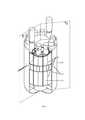
На фиг. 1 представлен 3-D вид реакторной установки в соответствии с предлагаемым техническим решением.FIG. 1 shows a 3-D view of the reactor plant in accordance with the proposed technical solution.
На фиг. 2 представлен фрагмент А 3-D вида реакторной установки с указанием направления течения теплоносителя в зазорах между блоками.FIG. 2 shows a fragment A 3-D of a view of the reactor plant with an indication of the direction of flow of the coolant in the gaps between the blocks.
На фиг. 3 представлен вертикальный разрез 1-1 реакторной установки по насосу и парогенератору. На Фиг. 3 стрелками отражена схема циркуляции теплоносителя в реакторе интегрального типа, основной особенностью которого является размещение в одном корпусе активной зоны, насоса, обеспечивающего циркуляцию теплоносителя, и парогенератора или теплообменника для отвода генерируемого в активной зоне тепла.FIG. 3 shows a vertical section 1-1 of the reactor plant along the pump and steam generator. FIG. 3, the arrows show the circulation diagram of the coolant in an integral type reactor, the main feature of which is the placement in one casing of the core, a pump that circulates the coolant, and a steam generator or heat exchanger to remove the heat generated in the core.
На фиг. 4 представлен горизонтальный разрез реактора между патрубков подвода теплоносителя к парогенератору и активной зоной.FIG. 4 shows a horizontal section of the reactor between the pipes for supplying the coolant to the steam generator and the core.
На фиг. 5 представлен фрагмент силового каркаса с размещенными в нем блоками, выполненными в виде контейнеров с карбидом бора (А), а также примеры возможных решений по выбору конструкции контейнеров (Б – Е). На фиг. 5Б показан фрагмент силового каркаса с разрезами (наполнитель условно не показан) и перемещением элементов (по стрелкам). На фиг. 5В показана нижняя часть контейнера (наполнитель условно не показан). На фиг. 5Г представлен блок из контейнеров меньшего размера (наполнитель условно не показан), на который может быть заменен контейнер, показанный на фиг. 5В. На фиг. 5Д показан пучок стержневых контейнеров, на которые могут быть заменены контейнеры коробчатого типа. На фиг. 5Е представлен контейнер с внутренними каналами охлаждения (наполнитель условно не показан), на который может быть замещена группы контейнеров с внешним охлаждением.FIG. 5 shows a fragment of a load-bearing frame with blocks placed in it, made in the form of containers with boron carbide (A), as well as examples of possible solutions for choosing the design of containers (B - E). FIG. 5B shows a fragment of the load-bearing frame with cuts (the filler is not conventionally shown) and the movement of the elements (along the arrows). FIG. 5B shows the bottom of the container (filler not shown schematically). FIG. 5D shows a block of smaller containers (filler is not shown conventionally), which can be replaced with the container shown in FIG. 5B. FIG. 5E shows a bundle of core containers, with which box-type containers can be replaced. FIG. 5E shows a container with internal cooling channels (filler is not shown conventionally), which can be replaced with groups of containers with external cooling.
Вариант осуществления изобретенияAn embodiment of the invention
Далее описан возможный, но не единственный, вариант осуществления заявленного изобретения.The following describes a possible, but not the only, embodiment of the claimed invention.
Корпус реакторной установки (фиг. 3) содержит активную зону 1 с пробкой 2, циркуляционный насос 3, теплообменник 4, напорную камеру 5, основные каналы 6, нижнюю камеру 7, верхнюю камеру 8, патрубки 9, контейнеры 10.The body of the reactor plant (Fig. 3) contains an
В качестве теплоносителя используется тяжелый жидкометаллический теплоноситель на основе свинца или сплавов на основе свинца и висмута.A heavy liquid metal coolant based on lead or alloys based on lead and bismuth is used as a coolant.
Контейнеры 10 размещены как в низкотемпературной части первого контура реактора, так и в высокотемпературной части контура.The
Контейнеры 10 выполнены из коррозионностойкой в ТЖМТ, жаростойких и жаропрочных сталей аустенитной группы.
Контейнеры 10 заполняют все внутрикорпусное пространство, кроме опускного канала насоса 3, коллекторов над и под активной зоной 1. Контейнеры 10 совместно с обечайкой 11 вокруг активной зоны 1 с пробкой 2, обечайкой корпуса 12, радиальными ребрами 13 и кольцевыми горизонтальными ребрами 14 образуют силовой каркас корпуса. В кольцевых горизонтальных ребрах 14 организованы отверстия для прохода теплоносителя в вертикальном направлении. Форму отверстий выбирают исходя из удобства сварки силового каркаса, крепления блоков и обеспечения равномерной раздачи теплоносителя из коллекторов на вход в вертикально ориентированные щели. Форма отверстий может быть цилиндрической.
Размеры зазоров 15 (фиг. 2) между контейнерами 10 и элементами силового каркаса выбирают таким образом, чтобы при расходе теплоносителя, соответствующем номинальному уровню мощности ядерного реактора, режим течения был турбулентным.The dimensions of the gaps 15 (Fig. 2) between the
При выборе конкретной конструкции контейнеров, включая их объем, плотность и материал наполнителя (сталь или карбид бора в виде более плотных горячепрессованных блочков или менее плотной засыпки порошком) учитываются следующие факторы:When choosing a specific container design, including their volume, density and filler material (steel or boron carbide in the form of denser hot-pressed blocks or less dense powder filling), the following factors are taken into account:
- непревышение температур, при которых обеспечена совместимость материалов;- not exceeding the temperatures at which the compatibility of materials is ensured;
- непревышение температурой материалов блоков температуры выхода теплоносителя из активной зоны;- the temperature of the materials of the blocks does not exceed the temperature of the coolant outlet from the core;
- достаточность объема и массы материалов блоков для выполнения функции радиационной защиты корпуса и оборудования, расположенного в нем, а также теплоносителя второго контура;- sufficiency of the volume and mass of block materials to perform the function of radiation protection of the housing and equipment located in it, as well as the coolant of the secondary circuit;
- площадь сечения для прохода теплоносителя и смоченный периметр блоков и элементов силового каркаса должны быть такими, чтобы обеспечивался турбулентный режим течения теплоносителя во внутрикорпусном пространстве при расходе теплоносителя, соответствующем номинальному уровню мощности ядерного реактора.- the cross-sectional area for the passage of the coolant and the wetted perimeter of the blocks and elements of the load-bearing frame must be such that a turbulent flow of the coolant in the inside of the vessel space is ensured at a coolant flow rate corresponding to the nominal power level of the nuclear reactor.
Выполнение указанных выше критериев проверяется соответствующими расчетами, которые проводят с использованием известных расчетных методов.The fulfillment of the above criteria is verified by appropriate calculations, which are carried out using known calculation methods.
Существенное увеличение скорости в зазорах между блоками выше границы турбулентного режима нежелательно, так как приводит к увеличению гидравлического сопротивления. Существенное увеличение величины зазоров с уменьшением скорости и переходом к ламинарному режиму течения также нежелательно, так как ухудшает теплопередачу между теплоносителем и контейнерами.A significant increase in speed in the gaps between blocks above the turbulent boundary is undesirable, since it leads to an increase in hydraulic resistance. A significant increase in the size of the gaps with a decrease in the velocity and the transition to a laminar flow regime is also undesirable, since it impairs the heat transfer between the coolant and the containers.
Во время работы в штатном режиме холодный теплоноситель циркуляционным насосом 3 подают в напорную камеру 5, откуда по каналам 6 он поступает на вход в активную зону 1. В активной зоне 1 теплоноситель нагревается и поступает в объем над активной зоной 1, а затем поступает в патрубки 9, которые обеспечивают поступление горячего теплоносителя в парогенераторы или теплообменники второго контура (на фиг. трубная система теплообменников условно не показана). На Фиг. 1, 2 показано, что таких теплообменников с соответствующими им патрубками может быть несколько. После входа в теплообменники 4 теплоноситель разделяется на два потока. Часть теплоносителя, движущаяся вверх, охлаждается теплоносителем второго контура и поступает в верхнюю камеру 8. Часть теплоносителя, движущаяся вниз, также охлаждается теплоносителем второго контура и поступает в нижнюю камеру 7, где разворачивается в направлении движения вверх. При движении вверх большая часть теплоносителя движется во внутрикорпусном пространстве между блоками 10 и в конечном итоге также выходит в верхнюю камеру 8. Незначительная часть теплоносителя из нижней камеры 7 поступает на термостатирование корпуса реактора в зазор между корпусом 12 и обечайкой 11 (см. Фиг. 3). Соотношение расходов вверх и вниз теплообменника выбирается расчетом, таким образом, чтобы температуры теплоносителя первого контура на выходе двух потоков теплоносителя из теплообменника 4 были примерно равны с учетом их подогрева в каналах между контейнерами 10 и в канале термостатирования корпуса.During normal operation, the cold coolant is supplied by the
Конструкция контейнеров 10, исходя из необходимости одновременного достижения ключевых технических результатов, а именно, формирования требуемого состава радиационной защиты, увеличения теплоаккумулирующей способности первого контура реакторной установки, обеспечения требуемой теплопередачи к элементам, выполняющим функции теплового аккумулятора, снижения массы реакторной установки, может быть принята различной, как это показано на Фиг. 5.The design of
В качестве наполнителя блоков может использоваться не только карбид бора, но и в необходимых случаях могут использоваться и другие материалы. Например, вместо карбида бора для улучшения замедления нейтронов в локальных областях могут применяться известные материалы на основе гидридов тугоплавких металлов. Для улучшения защиты от гамма-излучения или увеличения теплоемкости может использоваться наполнитель контейнера из стали, или тонкостенный контейнер может быть заменен на цельный стальной блок, соответствующей геометрии. Для улучшения теплопередачи между теплоносителем и контейнером, а также исходя из удобства монтажа или технологии изготовления контейнеров сложной геометрической формы, контейнеры могут быть укрупнены с формированием внутренних каналов, как это показано в вариантах реализации на Фиг. 4.As a filler of blocks, not only boron carbide can be used, but other materials can also be used if necessary. For example, instead of boron carbide, known materials based on refractory metal hydrides can be used to improve neutron moderation in local regions. To improve the gamma-ray shielding or increase the heat capacity, the container filler of steel can be used, or the thin-walled container can be replaced with a one-piece steel block that matches the geometry. To improve the heat transfer between the coolant and the container, as well as based on ease of installation or manufacturing technology of containers of complex geometric shapes, containers can be enlarged with the formation of internal channels, as shown in the embodiments in Figs. 4.
Свободный объем контейнеров 10 может сообщаться с объемом теплоносителя через специально организованные пробки, в которых помещен фильтр, изготовленный, например, из металлической проволоки, препятствующий попаданию карбида бора в первый контур. При этом обеспечивается улучшение теплопередачи между теплоносителем и материалами контейнера.The free volume of
Описанное размещение контейнеров 10 внутри корпуса реактора формирует тракт теплоносителя, по которому теплоноситель проходит при движении вверх из нижней камеры 7 в верхнюю камеру 8.The described placement of
В случае любого вида аварии приводящей к ухудшению отвода тепла от активной зоны, значительный объем блоков, выполненных из материала, с теплоемкостью большей, чем теплоемкость теплоносителя играет роль теплового аккумулятора. При этом теплоемкость блоков выше, чем теплоемкость вытесняемого ими теплоносителя, что в сочетании с развитой поверхностью контейнеров обеспечивает замедление роста температур на входе в активную зону и способствует повышению безопасности. Сформированные между блоками вертикальные каналы, ориентированные в направлении, соответствующем естественной конвекции, способствуют ее быстрому развитию в авариях с отключением циркуляционных насосов, что также способствует повышению безопасности.In the event of any type of accident leading to a deterioration in heat removal from the core, a significant volume of blocks made of material with a heat capacity greater than the heat capacity of the coolant plays the role of a heat accumulator. In this case, the heat capacity of the blocks is higher than the heat capacity of the coolant displaced by them, which, in combination with the developed surface of the containers, slows down the temperature rise at the inlet to the core and improves safety. The vertical channels formed between the blocks, oriented in the direction corresponding to natural convection, contribute to its rapid development in accidents with the shutdown of circulation pumps, which also contributes to an increase in safety.
Промышленная применимостьIndustrial applicability
Техническое решение согласно изобретению может быть использовано в энергетических установках с реактором с тяжелым жидкометаллическим теплоносителем (ТЖМТ) на основе свинца или сплавов на основе свинца и висмута. Предложенная конструкция ядерного реактора обеспечивает высокую степень безопасности.The technical solution according to the invention can be used in power plants with a reactor with a heavy liquid metal coolant (HLMC) based on lead or alloys based on lead and bismuth. The proposed design of a nuclear reactor provides a high degree of safety.
Claims (14)
Translated fromRussianPriority Applications (5)
| Application Number | Priority Date | Filing Date | Title |
|---|---|---|---|
| RU2021106582ARU2756230C1 (en) | 2021-03-15 | 2021-03-15 | Heavy liquid metal coolant nuclear reactor |
| US18/281,954US20240170167A1 (en) | 2021-03-15 | 2021-10-04 | Nuclear reactor with a heavy liquid metal coolant |
| CN202180095689.9ACN116982120B (en) | 2021-03-15 | 2021-10-04 | Nuclear reactor with heavy liquid metal coolant |
| PCT/RU2021/000425WO2022197206A1 (en) | 2021-03-15 | 2021-10-04 | Nuclear reactor with a heavy liquid metal coolant |
| SA523450703ASA523450703B1 (en) | 2021-03-15 | 2023-09-14 | Nuclear reactor with heavy liquid metal coolant |
Applications Claiming Priority (1)
| Application Number | Priority Date | Filing Date | Title |
|---|---|---|---|
| RU2021106582ARU2756230C1 (en) | 2021-03-15 | 2021-03-15 | Heavy liquid metal coolant nuclear reactor |
Publications (1)
| Publication Number | Publication Date |
|---|---|
| RU2756230C1true RU2756230C1 (en) | 2021-09-28 |
Family
ID=77999847
Family Applications (1)
| Application Number | Title | Priority Date | Filing Date |
|---|---|---|---|
| RU2021106582ARU2756230C1 (en) | 2021-03-15 | 2021-03-15 | Heavy liquid metal coolant nuclear reactor |
Country Status (5)
| Country | Link |
|---|---|
| US (1) | US20240170167A1 (en) |
| CN (1) | CN116982120B (en) |
| RU (1) | RU2756230C1 (en) |
| SA (1) | SA523450703B1 (en) |
| WO (1) | WO2022197206A1 (en) |
Cited By (1)
| Publication number | Priority date | Publication date | Assignee | Title |
|---|---|---|---|---|
| RU2778548C1 (en)* | 2020-12-01 | 2022-08-22 | Стэйт Пауэр Инвестмент Корпорейшн Ресёарч Инститьют | Nuclear reactor |
Citations (8)
| Publication number | Priority date | Publication date | Assignee | Title |
|---|---|---|---|---|
| DE4432705A1 (en)* | 1994-09-14 | 1995-07-27 | Detlef Steller | Steam generator for nuclear reactor |
| RU2247435C1 (en)* | 2003-07-14 | 2005-02-27 | Государственное образовательное учреждение высшего профессионального образования Нижегородский государственный технический университет (НГТУ) | Nuclear power plant |
| RU2313143C1 (en)* | 2006-06-20 | 2007-12-20 | Государственное образовательное учреждение высшего профессионального образования Нижегородский государственный технический университет (ГОУВПО НГТУ) | Nuclear power plant |
| US20080310575A1 (en)* | 2005-09-21 | 2008-12-18 | Luciano Cinotti | Nuclear Reactor, In Particular a Liquid-Metal-Cooled Nuclear Reactor |
| RU2473984C1 (en)* | 2011-05-12 | 2013-01-27 | Открытое акционерное общество "Центральное конструкторское бюро машиностроения" | Reactor plant |
| US8817942B2 (en)* | 2007-09-26 | 2014-08-26 | Del Nova Vis S.R.L. | Nuclear reactor, in particular pool-type nuclear reactor, with new-concept fuel elements |
| RU2545098C1 (en)* | 2014-01-31 | 2015-03-27 | Российская Федерация, от имени которой выступает Государственная корпорация по атомной энергии "Росатом" | Reactor plant with fast neutron reactor and lead coolant |
| EP3271923B1 (en)* | 2015-03-19 | 2019-05-01 | Hydromine Nuclear Energy S.A.R.L. | Nuclear reactor, in particular liquid-metal-cooled compact nuclear reactor |
Family Cites Families (3)
| Publication number | Priority date | Publication date | Assignee | Title |
|---|---|---|---|---|
| RU2596163C2 (en)* | 2014-12-30 | 2016-08-27 | Открытое Акционерное Общество "Акмэ-Инжиниринг" | Method of nuclear reactor core annealing and nuclear reactor |
| IT201600069589A1 (en)* | 2016-07-05 | 2018-01-05 | Luciano Cinotti | NUCLEAR REACTOR EQUIPPED WITH HIGH HEAT EXCHANGER |
| CN106683720B (en)* | 2017-01-13 | 2018-01-30 | 中国核动力研究设计院 | A kind of shell-and-tube lead-containing alloy cooled reactor |
- 2021
- 2021-03-15RURU2021106582Apatent/RU2756230C1/enactive
- 2021-10-04CNCN202180095689.9Apatent/CN116982120B/enactiveActive
- 2021-10-04WOPCT/RU2021/000425patent/WO2022197206A1/ennot_activeCeased
- 2021-10-04USUS18/281,954patent/US20240170167A1/enactivePending
- 2023
- 2023-09-14SASA523450703Apatent/SA523450703B1/enunknown
Patent Citations (8)
| Publication number | Priority date | Publication date | Assignee | Title |
|---|---|---|---|---|
| DE4432705A1 (en)* | 1994-09-14 | 1995-07-27 | Detlef Steller | Steam generator for nuclear reactor |
| RU2247435C1 (en)* | 2003-07-14 | 2005-02-27 | Государственное образовательное учреждение высшего профессионального образования Нижегородский государственный технический университет (НГТУ) | Nuclear power plant |
| US20080310575A1 (en)* | 2005-09-21 | 2008-12-18 | Luciano Cinotti | Nuclear Reactor, In Particular a Liquid-Metal-Cooled Nuclear Reactor |
| RU2313143C1 (en)* | 2006-06-20 | 2007-12-20 | Государственное образовательное учреждение высшего профессионального образования Нижегородский государственный технический университет (ГОУВПО НГТУ) | Nuclear power plant |
| US8817942B2 (en)* | 2007-09-26 | 2014-08-26 | Del Nova Vis S.R.L. | Nuclear reactor, in particular pool-type nuclear reactor, with new-concept fuel elements |
| RU2473984C1 (en)* | 2011-05-12 | 2013-01-27 | Открытое акционерное общество "Центральное конструкторское бюро машиностроения" | Reactor plant |
| RU2545098C1 (en)* | 2014-01-31 | 2015-03-27 | Российская Федерация, от имени которой выступает Государственная корпорация по атомной энергии "Росатом" | Reactor plant with fast neutron reactor and lead coolant |
| EP3271923B1 (en)* | 2015-03-19 | 2019-05-01 | Hydromine Nuclear Energy S.A.R.L. | Nuclear reactor, in particular liquid-metal-cooled compact nuclear reactor |
Cited By (3)
| Publication number | Priority date | Publication date | Assignee | Title |
|---|---|---|---|---|
| RU2778548C1 (en)* | 2020-12-01 | 2022-08-22 | Стэйт Пауэр Инвестмент Корпорейшн Ресёарч Инститьют | Nuclear reactor |
| RU2787572C1 (en)* | 2022-06-22 | 2023-01-11 | Федеральное государственное бюджетное учреждение "Национальный исследовательский центр "Курчатовский институт" | Liquid-salt nuclear reactor with cavity type core |
| RU228883U1 (en)* | 2024-05-05 | 2024-09-13 | Сергей Леонидович Лякишев | High-safety reactor plant with a fast-neutron core and natural circulation of lead-bismuth liquid metal coolant |
Also Published As
| Publication number | Publication date |
|---|---|
| CN116982120A (en) | 2023-10-31 |
| CN116982120B (en) | 2024-03-15 |
| SA523450703B1 (en) | 2024-10-23 |
| WO2022197206A1 (en) | 2022-09-22 |
| US20240170167A1 (en) | 2024-05-23 |
Similar Documents
| Publication | Publication Date | Title |
|---|---|---|
| US20220301729A1 (en) | Molten fuel reactor thermal management configurations | |
| US7139352B2 (en) | Reactivity control rod for core | |
| US5343506A (en) | Nuclear reactor installation with a core catcher device and method for exterior cooling of the latter by natural circulation | |
| CA2869561C (en) | Molten salt nuclear reactor | |
| US11728052B2 (en) | Fast spectrum molten chloride test reactors | |
| EP2973600B1 (en) | Supporting nuclear fuel assemblies | |
| KR20110106850A (en) | Reactor Vessel Coolant Deflection Shield | |
| RU2699229C1 (en) | Low-power fast neutron modular nuclear reactor with liquid metal heat carrier and reactor core (versions) | |
| RU2668230C1 (en) | Fast neutron nuclear reactor with liquid metal coolant | |
| JP2022097583A (en) | Reactor with ascending heat exchanger | |
| JPS6262308B2 (en) | ||
| JP4101422B2 (en) | Liquid metal cooled nuclear reactor and liquid metal cooled nuclear power plant | |
| US3186913A (en) | Graphite moderated nuclear reactor | |
| JPH0727050B2 (en) | Liquid metal cooled nuclear reactor with passive cooling system | |
| RU2756230C1 (en) | Heavy liquid metal coolant nuclear reactor | |
| EA042239B1 (en) | NUCLEAR REACTOR WITH HEAVY LIQUID METAL COOLANT | |
| RU2769102C1 (en) | Passive cooling system of a nuclear reactor | |
| JP4746911B2 (en) | Method for constructing fast reactor and fast reactor facility | |
| JP2003139881A (en) | Supercritical water cooled reactor, channel box, water rod and fuel assembly | |
| JPH04283691A (en) | Fuel bundle with coolant bypass flow passage | |
| JP7689408B1 (en) | Nuclear power systems and containment vessels | |
| RU145059U1 (en) | VERTICAL REACTOR WITH REMOVABLE NEUTRON REFLECTOR |