RU2753842C2 - Wide angle radiating cable - Google Patents
Wide angle radiating cableDownload PDFInfo
- Publication number
- RU2753842C2 RU2753842C2RU2019128556ARU2019128556ARU2753842C2RU 2753842 C2RU2753842 C2RU 2753842C2RU 2019128556 ARU2019128556 ARU 2019128556ARU 2019128556 ARU2019128556 ARU 2019128556ARU 2753842 C2RU2753842 C2RU 2753842C2
- Authority
- RU
- Russia
- Prior art keywords
- slotted
- conductive body
- radiating cable
- radiation angle
- slot
- Prior art date
Links
Images

Classifications
- H—ELECTRICITY
- H01—ELECTRIC ELEMENTS
- H01Q—ANTENNAS, i.e. RADIO AERIALS
- H01Q13/00—Waveguide horns or mouths; Slot antennas; Leaky-waveguide antennas; Equivalent structures causing radiation along the transmission path of a guided wave
- H01Q13/20—Non-resonant leaky-waveguide or transmission-line antennas; Equivalent structures causing radiation along the transmission path of a guided wave
- H01Q13/203—Leaky coaxial lines
- H—ELECTRICITY
- H01—ELECTRIC ELEMENTS
- H01P—WAVEGUIDES; RESONATORS, LINES, OR OTHER DEVICES OF THE WAVEGUIDE TYPE
- H01P3/00—Waveguides; Transmission lines of the waveguide type
- H01P3/02—Waveguides; Transmission lines of the waveguide type with two longitudinal conductors
- H01P3/06—Coaxial lines
- H—ELECTRICITY
- H01—ELECTRIC ELEMENTS
- H01Q—ANTENNAS, i.e. RADIO AERIALS
- H01Q13/00—Waveguide horns or mouths; Slot antennas; Leaky-waveguide antennas; Equivalent structures causing radiation along the transmission path of a guided wave
- H01Q13/20—Non-resonant leaky-waveguide or transmission-line antennas; Equivalent structures causing radiation along the transmission path of a guided wave
Landscapes
- Waveguide Aerials (AREA)
- Insulated Conductors (AREA)
Abstract
Description
Translated fromRussianОБЛАСТЬ ТЕХНИКИ, К КОТОРОЙ ОТНОСИТСЯ ИЗОБРЕТЕНИЕTECHNICAL FIELD OF THE INVENTION
Настоящее изобретение относится к области кабелей, и в частности к излучающему кабелю с широким углом излучения.The present invention relates to the field of cables, and in particular to a radiating cable with a wide radiation angle.
ПРЕДПОСЫЛКИ ИЗОБРЕТЕНИЯBACKGROUND OF THE INVENTION
Настоящий раздел предназначен для описания предпосылок или контекста вариантов осуществления настоящего изобретения, изложенных в пунктах формулы. Описания, приведенные в настоящем документе, не признаются известным уровнем техники, исходя из того, что они содержатся в этом разделе.This section is intended to describe the background or context of the embodiments of the present invention set forth in the claims. The descriptions given in this document are not recognized as prior art because they are contained in this section.
Излучающие кабели имеют как функцию передачи сигнала, так и функцию излучения антенны. Излучающий кабель может беспроводным способом сообщаться с внешним пространством через щели, образованные на наружном проводящем теле. Излучающий кабель имеет преимущества однородного охвата сигналом и простой установки. Таким образом, излучающий кабель широко используется в системах беспроводной связи, устанавливаемых в узких местах, таких как туннели, шахты, метрополитен, подземные галереи, а также в высокоскоростных поездах и закрытых помещениях, и имеет очень широкие перспективы развития. При охвате сетью беспроводной связи в силу сложности среды помещения для устранения мертвых зон сигнала для получения однородного охвата сигналом требуется больший радиальный угол излучения излучающего кабеля.Radiating cables have both a signal transmission function and an antenna radiation function. The radiating cable can wirelessly communicate with the external space through slots formed in the outer conductive body. Radiating cable has the advantages of uniform signal coverage and easy installation. Thus, the leaky cable is widely used in wireless communication systems installed in narrow places such as tunnels, mines, subways, underground galleries, as well as in high-speed trains and enclosed spaces, and has very broad development prospects. In wireless coverage, due to the complexity of the indoor environment, a larger radial angle of emission of the radiating cable is required to eliminate signal dead zones to obtain uniform signal coverage.
С развитием и частым применением технологии связи с целью удовлетворения требования к сигналам высокой частоты уменьшается размер щели излучающего кабеля. Следовательно, также уменьшается радиальный диапазон излучения излучающего кабеля при высокой частоте, таким образом, излучающий кабель не может удовлетворять требованию к широкоугольному охвату внутри помещений путем устранения мертвых зон сигнала. Вместе с этим, когда становится шире диапазон частот, существующая щель перестает соответствовать связи при низкой частоте и затуханию при высокой частоте. Таким образом, возрастает стоимость охвата сигналами внутри помещений.With the development and frequent use of communication technology in order to meet the requirement for high frequency signals, the slot size of the radiating cable is decreasing. Therefore, the radial range of the radiating cable at high frequency is also reduced, so the radiating cable cannot meet the indoor wide angle coverage requirement by eliminating signal dead zones. At the same time, when the frequency range becomes wider, the existing gap ceases to correspond to coupling at low frequency and attenuation at high frequency. This increases the cost of indoor coverage.
СУЩНОСТЬ ИЗОБРЕТЕНИЯSUMMARY OF THE INVENTION
Требуется создать излучающий кабель с широким углом излучения, который имеет широкий радиальный угол излучения 170 градусов или более, малые потери связи, хорошее соответствие высокой частоте и низкой частоте, большой радиальный охват сигналом и высокая однородность.It is required to provide a radiating cable with a wide angle of radiation, which has a wide radial angle of 170 degrees or more, low coupling loss, good match of high frequency and low frequency, large radial signal coverage and high uniformity.
В настоящем изобретении предложен излучающий кабель с широким углом излучения, содержащий в направлении от внутренней стороны к наружной стороне внутреннее проводящее тело, изолирующий слой, наружное проводящее тело и наружную защитную оболочку. Множество секций щелей образованы на стенке наружного проводящего тела, при этом секции щелей находятся на равных расстояниях друг от друга. Каждая секция щелей состоит из множества щелевых блоков. Каждый щелевой блок содержит множество щелевых элементов, независимых друг от друга.The present invention provides a wide-angle radiation cable having an inner conductive body, an insulating layer, an outer conductive body, and an outer protective sheath from the inside to the outside. A plurality of slot sections are formed on the wall of the outer conductive body, with the slot sections being equidistant from each other. Each slot section consists of a plurality of slot blocks. Each slotted unit contains a plurality of slotted elements, independent of each other.
Более того, каждый щелевой элемент 8 имеет длину от 1 до 200 мм и ширину от 0,1 до 10 мм.Moreover, each slotted
Более того, щелевые элементы перпендикулярно или наклонно пересекаются с осевым направлением наружного проводящего тела.Moreover, the slotted elements intersect perpendicularly or obliquely with the axial direction of the outer conductive body.
Более того, радиальный угол излучения каждого щелевого блока составляет от 170 градусов до 360 градусов.Moreover, the radial radiation angle of each slotted unit is from 170 degrees to 360 degrees.
Более того, щелевые элементы каждого щелевого блока отстоят друг от друга и не сообщаются друг с другом, при этом расстояние между двумя смежными концевыми частями двух смежных щелевых элементов на развернутой стенке наружного проводника составляет от 0,5 мм до 50 мм.Moreover, the slotted elements of each slotted block are spaced apart from each other and do not communicate with each other, while the distance between two adjacent end portions of two adjacent slotted elements on the unfolded wall of the outer conductor is from 0.5 mm to 50 mm.
Более того, каждая секция щелей содержит по меньшей мере один щелевой блок, при этом щелевые блоки размещены вдоль осевого направления наружного проводящего тела.Moreover, each slot section contains at least one slotted block, the slotted blocks being disposed along the axial direction of the outer conductive body.
Более того, расстояние между смежными щелевыми блоками одной и той же секции щелей вдоль осевого направления составляет от 1 мм до 1200 мм.Moreover, the distance between adjacent slotted blocks of the same slot section along the axial direction is 1 mm to 1200 mm.
Более того, направления смежных щелевых блоков одной и той же секции щелей идентичны друг другу или отличаются друг от друга.Moreover, the directions of adjacent slotted blocks of the same slot section are identical or different from each other.
Более того, секции щелей отстоят друг от друга на одно и то же расстояние вдоль осевого направления наружного проводящего тела, и расстояние составляет от 5 мм до 2000 мм.Moreover, the slot sections are spaced from each other by the same distance along the axial direction of the outer conductive body, and the distance is from 5 mm to 2000 mm.
Более того, каждый щелевой элемент является прямоугольным, L-образным, U-образным, треугольным, T-образным, E-образным или имеет другую отличающуюся структуру.Moreover, each slotted element is rectangular, L-shaped, U-shaped, triangular, T-shaped, E-shaped, or other different structure.
Более того, концевая часть каждого щелевого элемента содержит закругление, которое имеет радиус закругления от 0 мм до 5 мм.Moreover, the end portion of each slotted element contains a rounding that has a radius of rounding from 0 mm to 5 mm.
По сравнению с известным уровнем техники излучающий кабель с широким углом излучения согласно настоящему изобретению содержит в направлении изнутри наружу внутреннее проводящее тело, изолирующий слой, наружное проводящее тело и наружную защитную оболочку. Множество секций щелей образованы на стенке наружного проводящего тела, которые находятся на равных расстояниях друг от друга и состоят из множества щелевых блоков. Каждый щелевой блок содержит множество щелевых элементов, которые являются независимыми друг от друга. Для излучающего кабеля с широким углом излучения согласно настоящему изобретению за счет режима распределенного излучения достигается широкоугольное излучение. Предусмотрев множество независимых щелевых элементов в каждом щелевом блоке можно преодолеть проблемы, связанные с небольшой щелью, слабой интенсивностью излучения при низкой частоте и узким радиальным углом излучения при высокой частоте, обусловленным охватом сигналами высокой частоты. Щелевой элемент конкретной конструкции может снизить затухание при высокой частоте для того, чтобы излучающий кабель мог соответствовать связи при низкой частоте и затуханию при высокой частоте, имел хорошую способность к объединению сигналов и мог в значительной степени снизить стоимость охвата сигналами внутри помещений.Compared with the prior art, the wide-angle radiating cable according to the present invention comprises an inner conductive body, an insulating layer, an outer conductive body, and an outer protective sheath from the inside to the outside. A plurality of slot sections are formed on the wall of the outer conductive body, which are equidistant from each other and consist of a plurality of slot blocks. Each slotted unit contains a plurality of slotted elements that are independent of each other. For a wide-angle radiating cable according to the present invention, the distributed radiation mode achieves wide-angle radiation. By providing a plurality of independent slot elements in each slot unit, the problems associated with a small slot, low radiation intensity at low frequency, and narrow radial radiation angle at high frequency due to high frequency signal coverage can be overcome. A slotted element of a particular design can reduce high frequency attenuation so that the leaky cable can accommodate low frequency communications and high frequency attenuation, has good signal conditioning capability, and can greatly reduce the cost of indoor signal coverage.
КРАТКОЕ ОПИСАНИЕ ГРАФИЧЕСКИХ МАТЕРИАЛОВBRIEF DESCRIPTION OF THE GRAPHIC MATERIALS
С целью иллюстрации вариантов осуществления настоящего изобретения для иллюстрации вариантов осуществления приведены описания.For the purpose of illustrating embodiments of the present invention, descriptions are provided to illustrate the embodiments.
На фиг. 1 представлено схематическое изображение первого варианта осуществления излучающего кабеля с широким углом излучения согласно настоящему изобретению.FIG. 1 is a schematic diagram of a first embodiment of a wide-angle radiating cable according to the present invention.
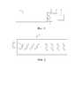
На фиг. 2 представлено схематическое изображение второго варианта осуществления наружного проводящего тела согласно фиг. 1.FIG. 2 is a schematic view of a second embodiment of the outer conductive body according to FIG. 1.
На фиг. 3 представлено схематическое изображение третьего варианта осуществления наружного проводящего тела согласно фиг. 1.FIG. 3 is a schematic view of a third embodiment of the outer conductive body according to FIG. 1.
На фиг. 4 представлено схематическое изображение четвертого варианта осуществления наружного проводящего тела согласно фиг. 1.FIG. 4 is a schematic view of a fourth embodiment of the outer conductive body according to FIG. 1.
На графических материалах числа обозначают следующее:In graphic materials, numbers mean the following:
ПОДРОБНОЕ ОПИСАНИЕDETAILED DESCRIPTION
Ниже будут описаны варианты реализации настоящего изобретения исключительно посредством вариантов осуществления со ссылкой на графические материалы. Варианты осуществления, показанные и описанные выше, являются исключительно примерами. Следует отметить, что отличительные признаки в вариантах осуществления настоящего изобретения могут быть объединены друг с другом без противоречий.Below, embodiments of the present invention will be described solely by means of the embodiments with reference to the drawings. The embodiments shown and described above are examples only. It should be noted that the features in the embodiments of the present invention can be combined with each other without conflict.
Варианты осуществления, показанные и описанные выше, являются исключительно примерами. Настоящее раскрытие сущности изобретения является исключительно иллюстративным, и в подробное описание могут быть внесены изменения в рамках принципов настоящего изобретения, вплоть до изменений в полной мере, установленной широким общим значением терминов, используемых в формуле изобретения. Поэтому следует иметь в виду, что варианты осуществления, описанные выше, могут быть изменены в пределах объема формулы изобретения.The embodiments shown and described above are examples only. The present disclosure is illustrative only, and the detailed description is subject to change within the framework of the principles of the present invention, up to the full extent established by the broad general meaning of the terms used in the claims. Therefore, it should be borne in mind that the embodiments described above may be varied within the scope of the claims.
Если не указано иное, все технические и научные термины, употребляемые в настоящем документе, имеют то же самое значение, обычно понимаемое специалистами в данной области техники. Терминология, употребляемая в описании настоящего изобретения, служит для описания вариантов осуществления и не предназначена для ограничения вариантов осуществления настоящего изобретения.Unless otherwise indicated, all technical and scientific terms used herein have the same meaning as commonly understood by those of ordinary skill in the art. The terminology used in the description of the present invention serves to describe the embodiments and is not intended to limit the embodiments of the present invention.
Как показано на фиг. 1, излучающий кабель с широким углом излучения согласно настоящему изобретению содержит в направлении от внутренней стороны к наружной стороне:As shown in FIG. 1, a wide-angle radiating cable according to the present invention comprises, in the direction from the inside to the outside:
Внутреннее проводящее тело 1. Внутреннее проводящее тело 1 может быть медным проводником, алюминиевым проводником, алюминиевым проводником с гальваническим медным плакированием, медным проводником с гальваническим медным плакированием, алюминиевым проводником с медным плакированием, медным проводником с медным плакированием или стальным проводником с медным плакированием. В одном варианте осуществления внутреннее проводящее тело 1 может быть сформировано путем сварки в продольном направлении полоски меди с получением медной трубки и вытравливания спиральных складок на медной трубке. В одном варианте осуществления его сечение является круглым.Inner
Изолирующий слой 2, используемый в качестве покрытия на наружной стороне внутреннего проводящего тела 1. В одном варианте осуществления изолирующий слой 2 может быть изготовлен из вспененного полиэтилена, политетрафторэтилена (PTFE) или фторированного этиленпропилена (FEP, также известного как сополимер перфторэтилена и пропилена).Insulating layer 2 used as a coating on the outside of the inner
Наружное проводящее тело 3, образующее множество секций щелей на стенке наружного проводящего тела 3. Секции щелей находятся на равных расстояниях друг от друга. Каждая секция щелей состоит из множества щелевых блоков 7. Каждый щелевой блок 7 содержит множество отдельных щелевых элементов 8. Щелевые элементы 8 являются независимыми друг от друга, и могут быть отделены друг от друга или сообщаться друг с другом.The outer
Как показано на фиг. 1, в первом варианте осуществления секции щелей размещены в ряду на стенке круглого наружного проводящего тела 3 вдоль осевого направления наружного проводящего тела 3. Щелевые блоки 7 каждой секции щелей имеют одно и то же направление и наклонно пересекаются с осевым направлением наружного проводящего тела 3. Каждый щелевой блок 7 содержит два щелевых элемента 8, расположенных на двух поперечных листах, которые отстоят друг от друга и параллельны друг другу. Каждый щелевой элемент 8 является прямоугольным. Когда щелевые блоки 7 проецируют на плоскость продольного сечения, проходящую через ось центра, концевые части щелевых элементов 8 одного и того же щелевого блока 7, которые являются смежными друг с другом, имеют радиус закругления 0,2 мм, а другие концевые части, которые находятся далеко друг от друга, имеют радиус закругления 1,5 мм. Каждый щелевой элемент 8 имеет длину 18 мм и ширину 3 мм. Угол между каждым щелевым элементом 8 и осевым направлением составляет 45 градусов. Минимальное расстояние между двумя щелевыми элементами 8 составляет 3 мм. В этом варианте осуществления излучающий кабель имеет радиальный угол излучения 180 градусов и совместим с рабочими характеристиками от 80 до 3600 МГц.As shown in FIG. 1, in the first embodiment, the slot sections are arranged in a row on the wall of the circular outer
Как показано на фиг. 2, во втором варианте осуществления секции щелей образованы в ряду на стенке круглого наружного проводящего тела 3 вдоль осевого направления наружного проводящего тела 3, как показано на фигуре. Щелевые блоки 7 основной группы щелей размещены наподобие формы китайского символа «восемь». Секции щелей на каждой из левой стороны и правой стороны содержат четыре щелевых блока 7. Каждый щелевой блок 7 содержит два щелевых элемента 8, отстоящих друг от друга. Каждый щелевой элемент 8 является прямоугольным. Когда щелевые блоки 7 проецируют на продольную плоскость поперечного сечения, проходящую ось центра, концевые части щелевых элементов 8 одного и того же щелевого блока 7, которые являются смежными друг с другом, имеют радиус закругления 0,1 мм, а другие концевые части, которые находятся далеко друг от друга, имеют радиус закругления 1 мм. Каждый щелевой элемент 8 имеет длину 15 мм и ширину 2 мм. Для каждого щелевого блока 7 секций щелей на левой стороне минимальное расстояние между двумя смежными щелевыми элементами 8 составляет 2 мм, угол между верхними щелевыми элементами 8 щелевого блока 7 и осевым направлением составляет 55 градусов, угол между нижними щелевыми элементами 8 щелевого блока 7 и осевым направлением составляет 35 градусов, каждые два смежных щелевых блока 7 имеют одинаковое расстояние между ними вдоль направления оси, которое составляет 27 мм. Для каждого щелевого блока 7 секции щелей на правой стороне минимальное расстояние между двумя смежными щелевыми элементами 8 составляет 4 мм, угол между верхним щелевым элементом 8 щелевого блока 7 и осевым направлением составляет 110 градусов, угол между нижним щелевым элементом 8 щелевого блока 7 и осевым направлением составляет 125 градусов, каждые два смежных щелевых блока 7 имеют одинаковое расстояние между ними вдоль направления оси, которое составляет 27 мм. Расстояние между одним щелевым блоком 7, смежным с правой стороной секции щелей, и одним щелевым блоком 7, смежным с левой стороной секции щелей, вдоль осевого направления составляет 50 мм. В этом варианте осуществления излучающий кабель имеет радиальный угол излучения 200 градусов и совместим с рабочими характеристиками от 80 до 3800 МГц.As shown in FIG. 2, in the second embodiment, the slot sections are formed in a row on the wall of the circular outer
Как показано на фиг. 3, в третьем варианте осуществления секции щелей образованы в ряду на стенке круглого наружного проводящего тела 3 вдоль осевого направления наружного проводящего тела 3, как показано на фигуре. Щелевые блоки 7 секций щелей размещены наподобие формы китайского символа «восемь». Каждая секция щелей на каждой стороне содержит три щелевых блока 7. Каждый щелевой блок 7 содержит три щелевых элемента 8, расположенных на одной и той же плоскости поперечного сечения. Каждый щелевой элемент 8 является прямоугольным. Когда щелевые блоки 7 проецируют на продольную плоскость поперечного сечения, проходящую через ось центра, концевые части щелевых элементов 8 одного и того же щелевого блока 7 имеют радиус закругления 0 мм. Центральный щелевой элемент 8 каждого щелевого блока 7 имеет длину 8 мм. Как верхний щелевой элемент 8, так и нижний щелевой элемент 8 каждого щелевого блока 7 имеют длину 5 мм и ширину 2 мм. Для трех щелевых блоков 7 секции щелей на левой стороне два смежных щелевых элемента 8 имеют одинаковое минимальное расстояние, которое составляет 2 мм, угол между щелевыми элементами 8 и осевым направлением составляет 40 градусов, каждые два смежных щелевых блока 7 имеют одинаковое расстояние между ними вдоль направления оси, которое составляет 20 мм. Для трех щелевых блоков 7 секций щелей на правой стороне два смежных щелевых элемента 8 имеют одинаковое минимальное расстояние, которое составляет 2 мм, угол между щелевыми элементами 8 и осевым направлением составляет 140 градусов, каждые два смежных щелевых блока 7 имеют одинаковое расстояние между ними вдоль направления оси, которое составляет 20 мм. Расстояние между одним щелевым блоком 7, смежным с правой стороной секции щелей, и одним щелевым блоком 7, смежным с левой стороной секции щелей, вдоль осевого направления составляет 45 мм. В этом варианте осуществления излучающий кабель имеет радиальный угол излучения 220 градусов и совместим с рабочими характеристиками от 80 до 6000 МГц.As shown in FIG. 3, in the third embodiment, the slot sections are formed in a row on the wall of the circular outer
Как показано на фиг. 4, в четвертом варианте осуществления секции щелей образованы в ряду на развернутой стенке круглого наружного проводящего тела 3. Щелевые блоки 7 каждой секции щелей имеют направление, перпендикулярное осевому направлению наружного проводящего тела 3. Каждый щелевой блок 7 содержит два щелевых элемента 8, расположенных в одной и той же плоскости поперечного сечения. Каждый щелевой элемент 8 является прямоугольным. Когда щелевые блоки 7 проецируют на продольную плоскость поперечного сечения, проходящую через ось центра, концевые части каждого щелевого элемента имеют радиус закругления 0,3 мм. Каждый щелевой элемент 8 имеет длину 8 мм и ширину 3 мм. Каждые два смежных щелевых элемента 8 имеют одинаковое минимальное расстояние, которое составляет 1 мм. Расстояния между каждыми двумя смежными щелевыми блоками 7 слева направо вдоль осевого направления составляют 28 мм, 11 мм, 19 мм, 11 мм, 19 мм, 11 мм и 28 мм. В этом варианте осуществления излучающий кабель имеет радиальный угол излучения 185 градусов и совместим с рабочими характеристиками от 80 до 6000 МГц.As shown in FIG. 4, in the fourth embodiment, the slot sections are formed in a row on the unfolded wall of the circular outer
В других вариантах осуществления количество щелевых блоков 7 каждой секции щелей может составлять один или несколько и не ограничивается настоящим вариантом осуществления. В других вариантах осуществления каждый щелевой элемент 8 имеет длину от 1 до 200 мм и ширину от 0,1 до 10 мм, которые не ограничиваются настоящим вариантом осуществления. Минимальное расстояние между каждыми двумя смежными щелевыми блоками 8 на развернутой стенке наружного проводящего тела составляет от 0,5 до 50 мм и не ограничивается настоящим вариантом осуществления. Каждый щелевой элемент 8 может быть прямоугольным, L-образным, U-образным, треугольным, T-образным, E-образным или иметь другую отличающуюся структуру. В другом варианте осуществления угол каждого щелевого элемента 8 наклонно пересекается с наружным проводящим телом 3 и не ограничивается настоящим вариантом осуществления. В других вариантах осуществления направления щелевых блоков 7 одной и той же секции щелей и расстояния между ними могут быть частично идентичными, полностью идентичными или совершенно отличными друг от друга и не ограничиваются настоящим вариантом осуществления. В других вариантах осуществления расстояние между смежными щелевыми блоками 7 одной и той же секции щелей вдоль осевого направления составляет от 1 мм до 1200 мм и не ограничивается настоящим вариантом осуществления. В других вариантах осуществления щелевые блоки 7 одной и той же секции щелей могут иметь одно и то же направление, разные направления или могут также пересекаться на разных плоскостях. В других вариантах осуществления направления щелевых элементов 8 одного и того же щелевого блока 7 могут быть частично идентичными, полностью идентичными или совершенно отличными друг от друга. Микроугловое смещение, вызванное дефектом обработки, относится к нормальным системным дефектам, что находится в рамках принципов настоящего изобретения.In other embodiments, the number of slotted
В настоящем варианте осуществления секции щелей, показанные на фиг. 1–4, образованы в качестве основного узла щелей, образованных на наружном проводящем теле. На практике множество таких основных узлов размещают на наружном проводящем теле для достижения функциональных требований. В настоящем варианте осуществления расстояние между смежными основными узлами может составлять 210 мм, 262 мм и т. д. Можно понять, что расстояние может варьировать от 5 мм до 2000 мм в зависимости от количества щелевых блоков 7 и щелевых элементов 8, содержащихся в них. Для удовлетворения требований к проектированию рабочих характеристик варьирование не ограничивается настоящим вариантом осуществления. Исходя из объединенного проектирования щелевых блоков 7 и щелевых элементов 8, радиальный угол излучения может быть увеличен от 170 градусов до 360 градусов и не ограничивается настоящим вариантом осуществления.In the present embodiment, the slot sections shown in FIG. 1-4 are formed as the main node of the slits formed on the outer conductive body. In practice, a plurality of such core assemblies are placed on the outer conductive body to achieve functional requirements. In the present embodiment, the distance between adjacent main units may be 210 mm, 262 mm, etc. It can be understood that the distance may vary from 5 mm to 2000 mm depending on the number of slotted
Наружная защитная оболочка 4, охватывающая наружный слой наружного проводящего тела 3. Наружная защитная оболочка 4 изготовлена из полиэтилена или пламезамедляющего полиолефина. В настоящем варианте осуществления ее сечение может быть круглым, полукруглым, прямоугольным, веерообразным или иметь другую отличающуюся структуру.Outer protective sheath 4 enclosing the outer layer of the outer
В итоге, для излучающего кабеля с широким углом излучения согласно настоящему изобретению за счет режима распределенного излучения достигается широкоугольное излучение. Излучающий кабель с широким углом излучения имеет радиальный угол излучения, который достигает 170 градусов или больше и соответствует связи при низкой частоте и затуханию при высокой частоте. Таким образом, излучающий кабель с широким углом излучения подходит для передачи на дальние расстояния и зоны охвата сверхвысокочастотными сигналами, имеет хорошую способность к объединению сигналов и может в значительной степени снизить стоимость охвата сигналами внутри помещений.As a result, for the wide-angle radiating cable according to the present invention, the distributed radiation mode achieves wide-angle radiation. A wide-angle emitting cable has a radial emission angle that reaches 170 degrees or more, and corresponds to low frequency coupling and high frequency attenuation. Thus, a wide angle radiating cable is suitable for long distance transmission and microwave coverage areas, has good signal consolidation ability, and can greatly reduce the cost of indoor signal coverage.
Варианты осуществления, показанные и описанные выше, являются исключительно примерами. Настоящее раскрытие сущности изобретения является исключительно иллюстративным, и в подробное описание могут быть внесены изменения в рамках принципов настоящего изобретения, вплоть до изменений в полной мере, установленной широким общим значением терминов, используемых в формуле изобретения. Поэтому следует иметь в виду, что варианты осуществления, описанные выше, могут быть изменены в пределах объема формулы изобретения.The embodiments shown and described above are examples only. The present disclosure is illustrative only, and the detailed description is subject to change within the framework of the principles of the present invention, up to the full extent established by the broad general meaning of the terms used in the claims. Therefore, it should be borne in mind that the embodiments described above may be varied within the scope of the claims.
Claims (9)
Translated fromRussianApplications Claiming Priority (1)
| Application Number | Priority Date | Filing Date | Title |
|---|---|---|---|
| PCT/CN2018/117275WO2020103150A1 (en) | 2018-11-23 | 2018-11-23 | Wide-angle radiation leaky coaxial cable |
Publications (3)
| Publication Number | Publication Date |
|---|---|
| RU2019128556A RU2019128556A (en) | 2020-10-14 |
| RU2019128556A3 RU2019128556A3 (en) | 2021-01-28 |
| RU2753842C2true RU2753842C2 (en) | 2021-08-24 |
Family
ID=70113817
Family Applications (1)
| Application Number | Title | Priority Date | Filing Date |
|---|---|---|---|
| RU2019128556ARU2753842C2 (en) | 2018-11-23 | 2018-11-23 | Wide angle radiating cable |
Country Status (4)
| Country | Link |
|---|---|
| EP (1) | EP3890114A4 (en) |
| CN (1) | CN111009733B (en) |
| RU (1) | RU2753842C2 (en) |
| WO (1) | WO2020103150A1 (en) |
Cited By (1)
| Publication number | Priority date | Publication date | Assignee | Title |
|---|---|---|---|---|
| RU223771U1 (en)* | 2023-11-03 | 2024-03-04 | Акционерное общество "Особое конструкторское бюро кабельной промышленности" | RADIATING CABLE |
Families Citing this family (5)
| Publication number | Priority date | Publication date | Assignee | Title |
|---|---|---|---|---|
| CN112803168A (en)* | 2021-02-03 | 2021-05-14 | 江苏亨鑫科技有限公司 | Wide-beam radiation leakage coaxial cable |
| CN112822694A (en)* | 2021-02-03 | 2021-05-18 | 江苏亨鑫科技有限公司 | Indoor wireless signal covering leaky cable arrangement method and corresponding arrangement structure |
| CN112803169A (en)* | 2021-02-03 | 2021-05-14 | 江苏亨鑫科技有限公司 | Radiation enhancement type leakage coaxial cable |
| CN113410646B (en)* | 2021-06-16 | 2024-07-30 | 中天射频电缆有限公司 | Leakage cable |
| US20240006093A1 (en)* | 2022-02-14 | 2024-01-04 | Global Energy Transmission, Co. | Wireless power transfer system with receiving antenna that achieves inductive coupling |
Citations (5)
| Publication number | Priority date | Publication date | Assignee | Title |
|---|---|---|---|---|
| RU2265923C1 (en)* | 2005-02-24 | 2005-12-10 | Закрытое акционерное общество "Автоматизированные информационные системы и телекоммуникации" | Radiating cable |
| CN102013540A (en)* | 2010-12-10 | 2011-04-13 | 北京交通大学 | Leaky coaxial cable for radiating circular polarization waves in circumferential 260 DEG range |
| CN102290625A (en)* | 2011-06-09 | 2011-12-21 | 中天日立射频电缆有限公司 | Leaky coaxial cable |
| CN108390155A (en)* | 2018-04-10 | 2018-08-10 | 中天射频电缆有限公司 | A kind of wide-angle radial leak coaxial cable |
| CN208028215U (en)* | 2018-04-10 | 2018-10-30 | 中天射频电缆有限公司 | A kind of wide-angle radial leak coaxial cable |
Family Cites Families (12)
| Publication number | Priority date | Publication date | Assignee | Title |
|---|---|---|---|---|
| BE1010528A5 (en)* | 1995-04-07 | 1998-10-06 | Inst Scient De Service Public | Online high frequency radiant. |
| JPH10145136A (en)* | 1996-11-08 | 1998-05-29 | Hitachi Cable Ltd | Leaky coaxial cable |
| KR100761599B1 (en)* | 2006-02-22 | 2007-09-27 | 엘에스전선 주식회사 | Single Beam Radial Leakage Coaxial Cable |
| CN101587978A (en)* | 2009-07-09 | 2009-11-25 | 江苏俊知技术有限公司 | Radial leak coaxial cable |
| CN101895000A (en)* | 2010-07-23 | 2010-11-24 | 中国西电集团公司 | Leaking coaxial cable |
| CN202019044U (en)* | 2011-05-13 | 2011-10-26 | 冯嵩 | Hole-slot type variable-coupling self-equalized power leakage coaxial cable |
| CN102683783A (en)* | 2012-05-16 | 2012-09-19 | 江苏亨鑫科技有限公司 | Low-loss radiation-type leakage coaxial cable |
| CN103151591B (en)* | 2013-03-21 | 2015-09-16 | 江苏亨鑫科技有限公司 | A kind of wide high-frequency low-consumption homogeneous radiation leaky coaxial cable |
| CN204464427U (en)* | 2014-12-20 | 2015-07-08 | 天津安讯达科技有限公司 | A kind of 5/4 cun of aluminium outer conductor radiation high-power leaky radio-frequency cable |
| CN204680737U (en)* | 2015-06-10 | 2015-09-30 | 杭州富通电线电缆有限公司 | A kind of leaky coaxial cable |
| JP2018088586A (en)* | 2016-11-28 | 2018-06-07 | 日立金属株式会社 | Leakage coaxial cable |
| CN108808255B (en)* | 2017-04-28 | 2020-12-11 | 中天射频电缆有限公司 | Leakage coaxial cable |
- 2018
- 2018-11-23RURU2019128556Apatent/RU2753842C2/enactive
- 2018-11-23WOPCT/CN2018/117275patent/WO2020103150A1/ennot_activeCeased
- 2018-11-23EPEP18918415.3Apatent/EP3890114A4/enactivePending
- 2019
- 2019-11-22CNCN201911155415.5Apatent/CN111009733B/enactiveActive
Patent Citations (5)
| Publication number | Priority date | Publication date | Assignee | Title |
|---|---|---|---|---|
| RU2265923C1 (en)* | 2005-02-24 | 2005-12-10 | Закрытое акционерное общество "Автоматизированные информационные системы и телекоммуникации" | Radiating cable |
| CN102013540A (en)* | 2010-12-10 | 2011-04-13 | 北京交通大学 | Leaky coaxial cable for radiating circular polarization waves in circumferential 260 DEG range |
| CN102290625A (en)* | 2011-06-09 | 2011-12-21 | 中天日立射频电缆有限公司 | Leaky coaxial cable |
| CN108390155A (en)* | 2018-04-10 | 2018-08-10 | 中天射频电缆有限公司 | A kind of wide-angle radial leak coaxial cable |
| CN208028215U (en)* | 2018-04-10 | 2018-10-30 | 中天射频电缆有限公司 | A kind of wide-angle radial leak coaxial cable |
Cited By (1)
| Publication number | Priority date | Publication date | Assignee | Title |
|---|---|---|---|---|
| RU223771U1 (en)* | 2023-11-03 | 2024-03-04 | Акционерное общество "Особое конструкторское бюро кабельной промышленности" | RADIATING CABLE |
Also Published As
| Publication number | Publication date |
|---|---|
| RU2019128556A3 (en) | 2021-01-28 |
| RU2019128556A (en) | 2020-10-14 |
| EP3890114A1 (en) | 2021-10-06 |
| WO2020103150A1 (en) | 2020-05-28 |
| EP3890114A4 (en) | 2022-06-22 |
| CN111009733A (en) | 2020-04-14 |
| CN111009733B (en) | 2022-09-30 |
Similar Documents
| Publication | Publication Date | Title |
|---|---|---|
| RU2753842C2 (en) | Wide angle radiating cable | |
| CN108390155B (en) | Wide-angle radiation type leaky coaxial cable | |
| US9112283B2 (en) | Multi-channel cabling for RF signal distribution | |
| US8384499B2 (en) | Leaky cable having at least one slot row for propagating electromagnetic waves that have been diffracted backwards | |
| US10784584B1 (en) | Radiating coaxial cable configured to transmit power and data | |
| CN110520941B (en) | Radiation cable and method for manufacturing radiation cable | |
| WO2021031641A1 (en) | Wide/high-frequency leaky cable | |
| US6288328B1 (en) | Coaxial cable having effective insulated conductor rotation | |
| US6292072B1 (en) | Radiating coaxial cable having groups of spaced apertures for generating a surface wave at a low frequencies and a combination of surface and radiated waves at higher frequencies | |
| WO2021170152A1 (en) | Fusion-type leaky cable and coverage system | |
| CN109066033B (en) | Longitudinally-wrapped flexible waveguide leaky cable | |
| CN106340703B (en) | High-isolation three-coaxial leaky coaxial cable | |
| US20230282393A1 (en) | Hybrid high frequency separator with parametric control ratios of conductive components | |
| CN113497359A (en) | Radiation coaxial cable | |
| US6426685B2 (en) | Radiating coaxial radio-frequency cable | |
| EP4037100A1 (en) | Radiating coaxial cable | |
| CN216361536U (en) | Equal-level waveguide tube for unmanned aerial vehicle defense system | |
| RU223771U1 (en) | RADIATING CABLE | |
| KR20210009282A (en) | Radiated Mode Leakage Coaxial Cable For FM Radio And DMB Broadcasting | |
| CN211700572U (en) | Ultra-wide band and ridge corrugated feed horn antenna | |
| KR102600253B1 (en) | Leaky Coaxial Cable for Public safety network | |
| CN119009494A (en) | Leaky cable applicable to 3.5GHz wide high-frequency radiation | |
| Diehl et al. | Wireless RF distribution in buildings using heating and ventilation ducts | |
| US20010002117A1 (en) | Radiating coaxial high frequency cable | |
| CN211670326U (en) | Ultra-wideband ridge corrugated horn antenna |