RU2753781C1 - Cable lock - Google Patents
Cable lockDownload PDFInfo
- Publication number
- RU2753781C1 RU2753781C1RU2020140098ARU2020140098ARU2753781C1RU 2753781 C1RU2753781 C1RU 2753781C1RU 2020140098 ARU2020140098 ARU 2020140098ARU 2020140098 ARU2020140098 ARU 2020140098ARU 2753781 C1RU2753781 C1RU 2753781C1
- Authority
- RU
- Russia
- Prior art keywords
- lock
- drum
- locking
- rope
- tip
- Prior art date
Links
Images

Classifications
- E—FIXED CONSTRUCTIONS
- E05—LOCKS; KEYS; WINDOW OR DOOR FITTINGS; SAFES
- E05B—LOCKS; ACCESSORIES THEREFOR; HANDCUFFS
- E05B39/00—Locks giving indication of authorised or unauthorised unlocking
Landscapes
- Lock And Its Accessories (AREA)
Abstract
Description
Translated fromRussianИзобретение, преимущественно, относится к устройствам для защиты дверей грузовых автофургонов от проникновения к перевозимому в них грузу посторонних лиц или злоумышленников и может быть использовано также для запирания любых объектов, оборудованных дверными закидками.The invention mainly relates to devices for protecting the doors of cargo vans from penetration of unauthorized persons or intruders into the cargo transported in them and can also be used to lock any objects equipped with door closures.
Известен навесной замок (патент РФ № 2596111), состоящий из корпуса и дужки. Дужка имеет U-образную форму. Когда замок закрыт, оба конца дужки заблокированы внутри корпуса. Когда замок отпирается, дужка может быть извлечена из корпуса таким образом, что один конец дужки может отделяться от корпуса, а второй остается внутри корпуса. В корпусе замка размещена ключевая личинка, которая взаимодействует с дужкой через запирающий элемент. Личинка замка может быть закрыта или открыта с использованием ключа, т.е. личинка замка может быть повернута в запирающее положение или в открытое положение. В открытом положении запирающий элемент позволяет извлекать дужку из корпуса. Запирающий элемент, как правило, представляет из себя шарик или цилиндрический стержень с заостренным торцом.Known padlock (RF patent No. 2596111), consisting of a body and a bow. The bow is U-shaped. When the lock is closed, both ends of the shackle are locked inside the case. When the lock is unlocked, the shackle can be removed from the body so that one end of the shackle can be separated from the body while the other remains inside the body. A key larva is placed in the lock body, which interacts with the shackle through the locking element. The lock cylinder can be locked or opened using a key, i.e. the lock cylinder can be turned to the locking position or to the open position. In the open position, the locking element allows the shackle to be removed from the body. The locking element, as a rule, is a ball or cylindrical rod with a pointed end.
Навесные замки могут использоваться для запирания самых различных объектов, например, входных дверей загородных домов, калиток, гаражных ворот и дверей автофургонов, оборудованных узлами запирания контейнерного типа (контейнерными закидками) и т.д.Padlocks can be used to lock a wide variety of objects, for example, front doors of country houses, gates, garage doors and doors of vans equipped with container-type locking units (container fillings), etc.
Недостатком известной конструкции является невозможность его использования на деформированных или нестандартных узлах запирания. От этих недостатков свободны замки, у которых дужка выполнена в виде отрезка каната, один конец которого неразъемно зафиксирован в корпусе, а на втором установлен наконечник с кольцевой проточкой, в которой в положении закрыто расположен запирающий элемент, взаимодействующий с ключевой личинкой, установленной в корпусе замка. Торец запирающего элемента, в положении закрыто, находится в кольцевой проточке наконечника, препятствуя ее извлечению из корпуса. При повороте ключа в личинке, торцевая часть запирающего элемента перестает взаимодействовать с канавкой наконечника и отрезок каната с наконечником может быть извлечен из корпуса замка.The disadvantage of the known design is the impossibility of using it on deformed or non-standard locking units. Locks are free from these drawbacks, in which the bow is made in the form of a piece of rope, one end of which is permanently fixed in the body, and on the second there is a tip with an annular groove, in which a locking element is located in the closed position, interacting with a key larva installed in the lock body ... The end of the locking element, in the closed position, is in the annular groove of the tip, preventing its removal from the body. When the key is turned in the larva, the end part of the locking element ceases to interact with the groove of the tip and a piece of rope with a tip can be removed from the lock body.
Недостатком описанной конструкции является невозможность затягивания каната до образования петли минимального размера, что бывает важно для предотвращения возможности вскрытия замка путем взлома, например, с помощью лома или фомки.The disadvantage of the described design is the impossibility of tightening the rope to the formation of a loop of the minimum size, which is important to prevent the possibility of opening the lock by breaking, for example, using a crowbar or crowbar.
Технический результат изобретения заключается в повышении надежности запирания за счет исключения возможности вскрытии замка путем взлома.Technical result The invention consists in increasing the reliability of locking by eliminating the possibility of opening the lock by breaking.
Указанный технический результат достигается за счет того, в тросовом замке, включающий корпус с дужкой, выполненной в виде отрезка каната, на одном конце которого установлен запирающий наконечник с кольцевыми проточками, одна из которых предназначена для предварительной фиксации наконечника в корпусе с помощью подпружиненного сферического фиксатора, а вторая проточка для окончательного запирания наконечника в корпусе замка с помощью ригеля, приводимого в движение через поводок ключевой вставки, а второй конец каната зафиксирован на поворотном барабане и намотан на нем, барабан размещен в корпусе замка, причем в барабане расположена спиральная пружина, которая возвращает излишне вытянутый канат на барабан, второй конец каната взаимодействует с запирающим механизмом барабана, выполненном в виде подпружиненного тела вращения и оснащен подпружиненной блокировочно-разблокировочной кнопкой, отключающей запирающий механизм барабана и позволяющий вытягивать канат из корпуса замка.The specified technical result is achieved due to the fact that in a cable lock, which includes a body with a bow made in the form of a piece of rope, at one end of which there is a locking tip with annular grooves, one of which is intended for preliminary fixation of the tip in the body using a spring-loaded spherical lock, and the second groove for the final locking of the tip in the lock body with the help of a bolt driven through the leash of the key insert, and the second end of the rope is fixed on the rotary drum and wound on it, the drum is placed in the lock body, and the drum contains a spiral spring that returns excessively stretched rope onto the drum, the second end of the rope interacts with the drum locking mechanism, made in the form of a spring-loaded rotating body and equipped with a spring-loaded lock-unlock button that disables the drum locking mechanism and allows the rope to be pulled out of the lock body.
Для привода ригеля может быть также использован шаговый электродвигатель, который через поводок, взаимодействует с ригелем, перемещая его на открывание и закрывание наконечника, а в корпусе для управления двигателем размещены контроллер управления, концевой выключатель контроля положения запирающего наконечника, контроллер обмена информацией с внешним устройством и источник питания. To drive the bolt, a stepper motor can also be used, which, through a leash, interacts with the bolt, moving it to open and close the tip, and a control controller, a limit switch for monitoring the position of the locking tip, a controller for exchanging information with an external device and power supply.
Поскольку заявленное устройство имеет ряд существенных признаков, отличающих его от наиболее близкого решения, оно соответствует условию патентоспособности «новизна».Since the claimed device has a number of essential features that distinguish it from the closest solution, it meets the "novelty" requirement of patentability.
В основу заявленного изобретения положены известные законы материального мира, что позволяет утверждать о соответствии изобретения условию «промышленная применимость».The claimed invention is based on the well-known laws of the material world, which makes it possible to assert that the invention meets the condition "industrial applicability".
Поскольку из уровня техники не известно выполнение конструкции тросового замка с изменяемой длиной охватывающего элемента (отрезка каната), следует сделать вывод о соответствии заявленного устройства условию «изобретательский уровень».Since the prior art does not know the implementation of the structure of the cable lock with a variable length of the covering element (rope segment), it should be concluded that the claimed device meets the condition "inventive step".
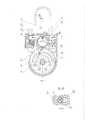
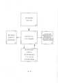
Изобретение иллюстрируется чертежами, где на фиг. 1 изображен внешний вид тросового замка со снятой крышкой, на фиг. 2 разрез А-А в зоне запирающего наконечника, на фиг. 3 разрез Б-Б тросового замка через ключевую вставку, на фиг. 4 также разрез Б-Б при использовании в качестве привода ригеля шагового электродвигателя, а на фиг. 5 блок-схема управления шаговым электродвигателем.The invention is illustrated in the drawings, where FIG. 1 shows the external view of a cable lock with the cover removed, FIG. 2 section A-A in the area of the locking tip, FIG. 3 section B-B of the cable lock through the key insert, in Fig. 4 also section BB when using a stepper motor as a drive of the bolt, and in FIG. 5 block diagram of stepper motor control.
Тросовый замок состоит из корпуса 1 и отрезка каната 2, один конец которого закреплен на барабане 3, размещенном в корпусе замка, причем в барабане расположена спиральная (часовая) пружина 4, которая позволяет возвращать вытянутый канат на барабан, уменьшая его длину. На втором конце каната размещен запирающий наконечник 5, который имеет две кольцевые проточки, одна из которых 6 предназначена для предварительной фиксации наконечника в корпусе с помощью подпружиненного сферического фиксатора 7, а вторая проточка 8 для окончательного запирания наконечника 5 в корпусе 1 замка с помощью ригеля 9, приводимого в движение через поводок 10 ключевой вставки 11. Второй конец каната взаимодействует с запирающим механизмом барабана 3, выполненном в виде подпружиненного тела вращения 12, например, шарика и оснащен подпружиненной блокировочно-разблокировочной кнопкой 13, при нажатии которой запирающий механизм барабана отключается и позволяет вытягивать канат из корпуса замка. Ригель с правой стороны имеет отверстие 14 и паз 15, который в закрытом состоянии взаимодействуют с кольцевой проточкой 8 на запирающем наконечнике 5, не давая возможности извлечь запирающий стержень. С левой стороны ригель также имеет отверстие и паз, который взаимодействует кольцевой проточкой 16 на кнопке. The cable lock consists of a
В случае, когда перемещение ригеля 9 осуществляется с помощью шагового электродвигателя 17, в конструкцию тросового замка дополнительно введены контроллер управления 18, концевой выключатель положения 19 запирающего наконечника 5, контроллер обмена информацией с внешним устройством 21 и источник питания 20.In the case when the movement of the
Устройство работает следующим образом:The device works as follows:
Замок поставляется в закрытом состоянии. Поворотом ключа ключевой вставки 11 ригель 9 под действием поводка 10 перемещают вправо, при этом наконечник 5 можно вынуть из корпуса 1. При навешивании тросового замка на закидку, следует нажать на кнопку 12, при этом шарик 12 перестает взаимодействовать с канатом 2 и канат можно извлечь из барабана на необходимую длину. Отпустив кнопку 13, канат 2 пропускают через проушины узла запирания (не показаны) и вставляют запирающий наконечник 5 в отверстие корпуса до момента западания подпружиненного сферического фиксатора 7 в проточку 6. Далее нажимают на кнопку 13, и канат под действием спиральной пружины 4 наматывается на барабан 3. После этого следует отпустить кнопку 13 и повернуть ключевую вставку 11 на запирание. Поводок 10 взаимодействует с ригелем 9, перемещая его влево, при этом паз 15 ригеля 9 входит во вторую проточку запирающего наконечника 5. Своим вторым пазом, расположенным на другой стороне ригеля 9, блокируется кнопка 13. Замок закрыт. The lock is delivered closed. By turning the key of the
Для снятия замка с узла запирания, поворачивают ключ в ключевой втавке, при этом поводок 10 перемещает ригель 9 вправо на открывание и пазы ригеля перестают взаимодействовать с проточками на запирающем наконечнике 5 и на кнопке 13. Далее следует нажать на кнопку 13 и вытянуть канат 2 на необходимую длину из корпуса замка, и извлечь запирающий наконечник 5 из корпуса замка и проушин закидки. Замок открыт.To remove the lock from the locking unit, turn the key in the key bushing, while the
В случае выполнения тросового замка, в котором перемещение ригеля осуществляется с помощью шагового электродвигателя, устройство работает следующим образом. После навешивания тросового замка на закидку и размещения излишков каната на барабане, с помощью внешнего источника, например, мобильного телефона, через контроллер обмена информацией 21, подается команда на закрытие замка через контроллер управления 18, которая поступает на шаговый электродвигатель 17. Электродвигатель, вращая поводок 10, перемещает ригель 9 влево на закрытие, при этом срабатывает концевой выключатель 19, сигнализирующий о том, что замок закрыт. В качестве источника питания 20 может быть использована аккумуляторная батарея с возможность её бесконтактной подзарядки.In the case of a cable lock, in which the movement of the crossbar is carried out using a stepping motor, the device operates as follows. After hanging the cable lock on the tuck and placing the excess rope on the drum, using an external source, for example, a mobile phone, through the
Claims (2)
Translated fromRussianPriority Applications (1)
| Application Number | Priority Date | Filing Date | Title |
|---|---|---|---|
| RU2020140098ARU2753781C1 (en) | 2020-12-07 | 2020-12-07 | Cable lock |
Applications Claiming Priority (1)
| Application Number | Priority Date | Filing Date | Title |
|---|---|---|---|
| RU2020140098ARU2753781C1 (en) | 2020-12-07 | 2020-12-07 | Cable lock |
Publications (1)
| Publication Number | Publication Date |
|---|---|
| RU2753781C1true RU2753781C1 (en) | 2021-08-23 |
Family
ID=77460300
Family Applications (1)
| Application Number | Title | Priority Date | Filing Date |
|---|---|---|---|
| RU2020140098ARU2753781C1 (en) | 2020-12-07 | 2020-12-07 | Cable lock |
Country Status (1)
| Country | Link |
|---|---|
| RU (1) | RU2753781C1 (en) |
Citations (5)
| Publication number | Priority date | Publication date | Assignee | Title |
|---|---|---|---|---|
| FR2378929A1 (en)* | 1977-01-26 | 1978-08-25 | Vachette Sa | Length adjustable tie for e.g. bicycle lock - has steel cable with ends anchored in block and wedged in hole by cylinder lock respectively |
| US4126024A (en)* | 1977-03-24 | 1978-11-21 | Timmons David R | Bicycle cable lock |
| FR2569991A1 (en)* | 1984-09-07 | 1986-03-14 | Antz Cabinet | Pocket-size anti-theft device for a pair of skis |
| SU1714066A1 (en)* | 1990-01-02 | 1992-02-23 | Луганский Станкостроительный Завод | Locking device |
| CN208845049U (en)* | 2018-07-26 | 2019-05-10 | 威洛克(深圳)智能科技有限公司 | Torsion spring type snap lock |
- 2020
- 2020-12-07RURU2020140098Apatent/RU2753781C1/enactive
Patent Citations (5)
| Publication number | Priority date | Publication date | Assignee | Title |
|---|---|---|---|---|
| FR2378929A1 (en)* | 1977-01-26 | 1978-08-25 | Vachette Sa | Length adjustable tie for e.g. bicycle lock - has steel cable with ends anchored in block and wedged in hole by cylinder lock respectively |
| US4126024A (en)* | 1977-03-24 | 1978-11-21 | Timmons David R | Bicycle cable lock |
| FR2569991A1 (en)* | 1984-09-07 | 1986-03-14 | Antz Cabinet | Pocket-size anti-theft device for a pair of skis |
| SU1714066A1 (en)* | 1990-01-02 | 1992-02-23 | Луганский Станкостроительный Завод | Locking device |
| CN208845049U (en)* | 2018-07-26 | 2019-05-10 | 威洛克(深圳)智能科技有限公司 | Torsion spring type snap lock |
Similar Documents
| Publication | Publication Date | Title |
|---|---|---|
| US9790716B2 (en) | Opposed hook sliding door lock | |
| CN105313792A (en) | Automatic closing arrangement for vehicle storage compartments | |
| JPH11515067A (en) | Automobile door lock or similar | |
| DK3140478T3 (en) | ELECTROMECHANICAL LOCKING UNIT | |
| US20060090527A1 (en) | Locking assembly for a truck cargo bed closure | |
| PT1842989E (en) | Mortise lock | |
| US5718135A (en) | Locks | |
| US4286814A (en) | Universally pivotal padlock and staple shielding hasp | |
| US12123222B2 (en) | Electronic locking apparatus for a swing door | |
| RU2753781C1 (en) | Cable lock | |
| CA2895850A1 (en) | Latch mechanism for an exit device | |
| ES2180302T3 (en) | KEYLESS ACCESS SYSTEM FOR VEHICLES. | |
| US9789852B2 (en) | Anti-theft device for a steering column and associated steering column | |
| US12424039B2 (en) | Intelligent lock and latch control system | |
| CN209761042U (en) | electric control lock structure for preventing impact and violent unlocking | |
| KR100446415B1 (en) | A disital door lock | |
| KR20170045598A (en) | Seat belt interlocking type of strike variableness apparatus for emergency door open | |
| KR20060043574A (en) | Locking device for the door handle | |
| CN206562846U (en) | A kind of intelligent anti-theft door | |
| KR102574820B1 (en) | Multi door lock for control box | |
| KR200438043Y1 (en) | Door handle device | |
| KR100391803B1 (en) | A door lock for an entrance door | |
| ES2704973T3 (en) | Lock mechanism | |
| EP1113134A2 (en) | Lock mechanism | |
| KR970005083Y1 (en) | Anti-theft door lock device |