RU2751585C1 - Pouring apparatus with a cartridge holder - Google Patents
Pouring apparatus with a cartridge holderDownload PDFInfo
- Publication number
- RU2751585C1 RU2751585C1RU2020116554ARU2020116554ARU2751585C1RU 2751585 C1RU2751585 C1RU 2751585C1RU 2020116554 ARU2020116554 ARU 2020116554ARU 2020116554 ARU2020116554 ARU 2020116554ARU 2751585 C1RU2751585 C1RU 2751585C1
- Authority
- RU
- Russia
- Prior art keywords
- cartridge
- compressed air
- holder
- beverage
- membrane
- Prior art date
Links
- 235000013361beverageNutrition0.000claimsabstractdescription81
- 238000002156mixingMethods0.000claimsabstractdescription65
- 239000000758substrateSubstances0.000claimsabstractdescription53
- 235000013305foodNutrition0.000claimsabstractdescription51
- 239000012528membraneSubstances0.000claimsabstractdescription51
- 239000003085diluting agentSubstances0.000claimsabstractdescription34
- 230000003213activating effectEffects0.000claimsdescription32
- 230000007246mechanismEffects0.000claimsdescription27
- 239000011796hollow space materialSubstances0.000claimsdescription18
- 238000007789sealingMethods0.000claimsdescription9
- 238000007664blowingMethods0.000claimsdescription4
- 239000007788liquidSubstances0.000abstractdescription24
- 239000000126substanceSubstances0.000abstractdescription6
- CURLTUGMZLYLDI-UHFFFAOYSA-NCarbon dioxideChemical compoundO=C=OCURLTUGMZLYLDI-UHFFFAOYSA-N0.000description36
- XLYOFNOQVPJJNP-UHFFFAOYSA-NwaterSubstancesOXLYOFNOQVPJJNP-UHFFFAOYSA-N0.000description30
- 239000006260foamSubstances0.000description21
- 238000000034methodMethods0.000description21
- 229910002092carbon dioxideInorganic materials0.000description18
- 239000001569carbon dioxideSubstances0.000description18
- 238000002360preparation methodMethods0.000description18
- 239000003795chemical substances by applicationSubstances0.000description15
- 230000004913activationEffects0.000description13
- 239000002904solventSubstances0.000description12
- 238000005057refrigerationMethods0.000description9
- 230000005540biological transmissionEffects0.000description8
- 239000012530fluidSubstances0.000description6
- 239000004033plasticSubstances0.000description6
- 230000015572biosynthetic processEffects0.000description5
- 238000011109contaminationMethods0.000description5
- 230000006870functionEffects0.000description5
- 229920006395saturated elastomerPolymers0.000description5
- 238000006073displacement reactionMethods0.000description4
- 239000011159matrix materialSubstances0.000description4
- 239000000203mixtureSubstances0.000description4
- 230000001105regulatory effectEffects0.000description4
- 235000014214soft drinkNutrition0.000description4
- 230000008901benefitEffects0.000description3
- 230000008859changeEffects0.000description3
- 230000006378damageEffects0.000description3
- 239000011521glassSubstances0.000description3
- 230000003287optical effectEffects0.000description3
- 239000012190activatorSubstances0.000description2
- 235000013405beerNutrition0.000description2
- RYYVLZVUVIJVGH-UHFFFAOYSA-NcaffeineChemical compoundCN1C(=O)N(C)C(=O)C2=C1N=CN2CRYYVLZVUVIJVGH-UHFFFAOYSA-N0.000description2
- 238000005266castingMethods0.000description2
- 239000011248coating agentSubstances0.000description2
- 239000012141concentrateSubstances0.000description2
- 238000002347injectionMethods0.000description2
- 239000007924injectionSubstances0.000description2
- 238000001746injection mouldingMethods0.000description2
- 239000007921spraySubstances0.000description2
- 230000002123temporal effectEffects0.000description2
- LPHGQDQBBGAPDZ-UHFFFAOYSA-NIsocaffeineNatural productsCN1C(=O)N(C)C(=O)C2=C1N(C)C=N2LPHGQDQBBGAPDZ-UHFFFAOYSA-N0.000description1
- 208000027418Wounds and injuryDiseases0.000description1
- 238000010521absorption reactionMethods0.000description1
- 230000001133accelerationEffects0.000description1
- 235000013334alcoholic beverageNutrition0.000description1
- 230000001476alcoholic effectEffects0.000description1
- 238000013459approachMethods0.000description1
- 238000000071blow mouldingMethods0.000description1
- 229960001948caffeineDrugs0.000description1
- VJEONQKOZGKCAK-UHFFFAOYSA-NcaffeineNatural productsCN1C(=O)N(C)C(=O)C2=C1C=CN2CVJEONQKOZGKCAK-UHFFFAOYSA-N0.000description1
- 238000006243chemical reactionMethods0.000description1
- 239000003638chemical reducing agentSubstances0.000description1
- 238000000576coating methodMethods0.000description1
- 238000004891communicationMethods0.000description1
- 230000006835compressionEffects0.000description1
- 238000000748compression mouldingMethods0.000description1
- 239000012897dilution mediumSubstances0.000description1
- 235000013399edible fruitsNutrition0.000description1
- 238000001595flow curveMethods0.000description1
- 239000011888foilSubstances0.000description1
- 235000011389fruit/vegetable juiceNutrition0.000description1
- 230000001939inductive effectEffects0.000description1
- 238000010102injection blow mouldingMethods0.000description1
- 208000014674injuryDiseases0.000description1
- 238000003780insertionMethods0.000description1
- 230000037431insertionEffects0.000description1
- 238000009434installationMethods0.000description1
- 230000010354integrationEffects0.000description1
- 238000004519manufacturing processMethods0.000description1
- 239000002991molded plasticSubstances0.000description1
- 235000019520non-alcoholic beverageNutrition0.000description1
- 230000008569processEffects0.000description1
- 230000009467reductionEffects0.000description1
- 238000009738saturatingMethods0.000description1
- 239000011343solid materialSubstances0.000description1
- 238000005507sprayingMethods0.000description1
- 239000003381stabilizerSubstances0.000description1
- 239000004753textileSubstances0.000description1
- 238000012546transferMethods0.000description1
- 238000003466weldingMethods0.000description1
Images


Classifications
- B—PERFORMING OPERATIONS; TRANSPORTING
- B67—OPENING, CLOSING OR CLEANING BOTTLES, JARS OR SIMILAR CONTAINERS; LIQUID HANDLING
- B67D—DISPENSING, DELIVERING OR TRANSFERRING LIQUIDS, NOT OTHERWISE PROVIDED FOR
- B67D1/00—Apparatus or devices for dispensing beverages on draught
- B67D1/08—Details
- B—PERFORMING OPERATIONS; TRANSPORTING
- B67—OPENING, CLOSING OR CLEANING BOTTLES, JARS OR SIMILAR CONTAINERS; LIQUID HANDLING
- B67D—DISPENSING, DELIVERING OR TRANSFERRING LIQUIDS, NOT OTHERWISE PROVIDED FOR
- B67D1/00—Apparatus or devices for dispensing beverages on draught
- B67D1/0042—Details of specific parts of the dispensers
- B67D1/0078—Ingredient cartridges
- B67D1/0079—Ingredient cartridges having their own dispensing means
- A—HUMAN NECESSITIES
- A23—FOODS OR FOODSTUFFS; TREATMENT THEREOF, NOT COVERED BY OTHER CLASSES
- A23L—FOODS, FOODSTUFFS OR NON-ALCOHOLIC BEVERAGES, NOT OTHERWISE PROVIDED FOR; PREPARATION OR TREATMENT THEREOF
- A23L2/00—Non-alcoholic beverages; Dry compositions or concentrates therefor; Preparation or treatment thereof
- A23L2/385—Concentrates of non-alcoholic beverages
- A23L2/39—Dry compositions
- A—HUMAN NECESSITIES
- A23—FOODS OR FOODSTUFFS; TREATMENT THEREOF, NOT COVERED BY OTHER CLASSES
- A23L—FOODS, FOODSTUFFS OR NON-ALCOHOLIC BEVERAGES, NOT OTHERWISE PROVIDED FOR; PREPARATION OR TREATMENT THEREOF
- A23L2/00—Non-alcoholic beverages; Dry compositions or concentrates therefor; Preparation or treatment thereof
- A23L2/52—Adding ingredients
- A23L2/54—Mixing with gases
- A—HUMAN NECESSITIES
- A47—FURNITURE; DOMESTIC ARTICLES OR APPLIANCES; COFFEE MILLS; SPICE MILLS; SUCTION CLEANERS IN GENERAL
- A47J—KITCHEN EQUIPMENT; COFFEE MILLS; SPICE MILLS; APPARATUS FOR MAKING BEVERAGES
- A47J31/00—Apparatus for making beverages
- A47J31/06—Filters or strainers for coffee or tea makers ; Holders therefor
- A47J31/0657—Filters or strainers for coffee or tea makers ; Holders therefor for brewing coffee under pressure, e.g. for espresso machines
- A47J31/0668—Filters or strainers for coffee or tea makers ; Holders therefor for brewing coffee under pressure, e.g. for espresso machines specially adapted for cartridges
- A47J31/0673—Means to perforate the cartridge for creating the beverage outlet
- A—HUMAN NECESSITIES
- A47—FURNITURE; DOMESTIC ARTICLES OR APPLIANCES; COFFEE MILLS; SPICE MILLS; SUCTION CLEANERS IN GENERAL
- A47J—KITCHEN EQUIPMENT; COFFEE MILLS; SPICE MILLS; APPARATUS FOR MAKING BEVERAGES
- A47J31/00—Apparatus for making beverages
- A47J31/24—Coffee-making apparatus in which hot water is passed through the filter under pressure, i.e. in which the coffee grounds are extracted under pressure
- A47J31/34—Coffee-making apparatus in which hot water is passed through the filter under pressure, i.e. in which the coffee grounds are extracted under pressure with hot water under liquid pressure
- A47J31/36—Coffee-making apparatus in which hot water is passed through the filter under pressure, i.e. in which the coffee grounds are extracted under pressure with hot water under liquid pressure with mechanical pressure-producing means
- A47J31/3604—Coffee-making apparatus in which hot water is passed through the filter under pressure, i.e. in which the coffee grounds are extracted under pressure with hot water under liquid pressure with mechanical pressure-producing means with a mechanism arranged to move the brewing chamber between loading, infusing and ejecting stations
- A47J31/3623—Cartridges being employed
- A47J31/3628—Perforating means therefor
- A—HUMAN NECESSITIES
- A47—FURNITURE; DOMESTIC ARTICLES OR APPLIANCES; COFFEE MILLS; SPICE MILLS; SUCTION CLEANERS IN GENERAL
- A47J—KITCHEN EQUIPMENT; COFFEE MILLS; SPICE MILLS; APPARATUS FOR MAKING BEVERAGES
- A47J31/00—Apparatus for making beverages
- A47J31/40—Beverage-making apparatus with dispensing means for adding a measured quantity of ingredients, e.g. coffee, water, sugar, cocoa, milk, tea
- A47J31/407—Beverage-making apparatus with dispensing means for adding a measured quantity of ingredients, e.g. coffee, water, sugar, cocoa, milk, tea with ingredient-containing cartridges; Cartridge-perforating means
- A—HUMAN NECESSITIES
- A47—FURNITURE; DOMESTIC ARTICLES OR APPLIANCES; COFFEE MILLS; SPICE MILLS; SUCTION CLEANERS IN GENERAL
- A47J—KITCHEN EQUIPMENT; COFFEE MILLS; SPICE MILLS; APPARATUS FOR MAKING BEVERAGES
- A47J31/00—Apparatus for making beverages
- A47J31/44—Parts or details or accessories of beverage-making apparatus
- A47J31/4403—Constructional details
- A47J31/441—Warming devices or supports for beverage containers
- A47J31/4425—Supports for beverage containers when filled or while being filled
- A—HUMAN NECESSITIES
- A47—FURNITURE; DOMESTIC ARTICLES OR APPLIANCES; COFFEE MILLS; SPICE MILLS; SUCTION CLEANERS IN GENERAL
- A47J—KITCHEN EQUIPMENT; COFFEE MILLS; SPICE MILLS; APPARATUS FOR MAKING BEVERAGES
- A47J31/00—Apparatus for making beverages
- A47J31/44—Parts or details or accessories of beverage-making apparatus
- A47J31/4492—Means to read code provided on ingredient pod or cartridge
- B—PERFORMING OPERATIONS; TRANSPORTING
- B65—CONVEYING; PACKING; STORING; HANDLING THIN OR FILAMENTARY MATERIAL
- B65D—CONTAINERS FOR STORAGE OR TRANSPORT OF ARTICLES OR MATERIALS, e.g. BAGS, BARRELS, BOTTLES, BOXES, CANS, CARTONS, CRATES, DRUMS, JARS, TANKS, HOPPERS, FORWARDING CONTAINERS; ACCESSORIES, CLOSURES, OR FITTINGS THEREFOR; PACKAGING ELEMENTS; PACKAGES
- B65D51/00—Closures not otherwise provided for
- B65D51/18—Arrangements of closures with protective outer cap-like covers or of two or more co-operating closures
- B65D51/20—Caps, lids, or covers co-operating with an inner closure arranged to be opened by piercing, cutting, or tearing
- B65D51/22—Caps, lids, or covers co-operating with an inner closure arranged to be opened by piercing, cutting, or tearing having means for piercing, cutting, or tearing the inner closure
- B65D51/221—Caps, lids, or covers co-operating with an inner closure arranged to be opened by piercing, cutting, or tearing having means for piercing, cutting, or tearing the inner closure a major part of the inner closure being left inside the container after the opening
- B65D51/222—Caps, lids, or covers co-operating with an inner closure arranged to be opened by piercing, cutting, or tearing having means for piercing, cutting, or tearing the inner closure a major part of the inner closure being left inside the container after the opening the piercing or cutting means being integral with, or fixedly attached to, the outer closure
- B65D51/223—Caps, lids, or covers co-operating with an inner closure arranged to be opened by piercing, cutting, or tearing having means for piercing, cutting, or tearing the inner closure a major part of the inner closure being left inside the container after the opening the piercing or cutting means being integral with, or fixedly attached to, the outer closure the outer closure having to be removed or inverted for piercing or cutting
- B—PERFORMING OPERATIONS; TRANSPORTING
- B65—CONVEYING; PACKING; STORING; HANDLING THIN OR FILAMENTARY MATERIAL
- B65D—CONTAINERS FOR STORAGE OR TRANSPORT OF ARTICLES OR MATERIALS, e.g. BAGS, BARRELS, BOTTLES, BOXES, CANS, CARTONS, CRATES, DRUMS, JARS, TANKS, HOPPERS, FORWARDING CONTAINERS; ACCESSORIES, CLOSURES, OR FITTINGS THEREFOR; PACKAGING ELEMENTS; PACKAGES
- B65D51/00—Closures not otherwise provided for
- B65D51/18—Arrangements of closures with protective outer cap-like covers or of two or more co-operating closures
- B65D51/20—Caps, lids, or covers co-operating with an inner closure arranged to be opened by piercing, cutting, or tearing
- B65D51/22—Caps, lids, or covers co-operating with an inner closure arranged to be opened by piercing, cutting, or tearing having means for piercing, cutting, or tearing the inner closure
- B65D51/221—Caps, lids, or covers co-operating with an inner closure arranged to be opened by piercing, cutting, or tearing having means for piercing, cutting, or tearing the inner closure a major part of the inner closure being left inside the container after the opening
- B65D51/226—Caps, lids, or covers co-operating with an inner closure arranged to be opened by piercing, cutting, or tearing having means for piercing, cutting, or tearing the inner closure a major part of the inner closure being left inside the container after the opening the piercing or cutting means being non integral with, or not fixedly attached to, the outer closure
- B—PERFORMING OPERATIONS; TRANSPORTING
- B65—CONVEYING; PACKING; STORING; HANDLING THIN OR FILAMENTARY MATERIAL
- B65D—CONTAINERS FOR STORAGE OR TRANSPORT OF ARTICLES OR MATERIALS, e.g. BAGS, BARRELS, BOTTLES, BOXES, CANS, CARTONS, CRATES, DRUMS, JARS, TANKS, HOPPERS, FORWARDING CONTAINERS; ACCESSORIES, CLOSURES, OR FITTINGS THEREFOR; PACKAGING ELEMENTS; PACKAGES
- B65D85/00—Containers, packaging elements or packages, specially adapted for particular articles or materials
- B65D85/70—Containers, packaging elements or packages, specially adapted for particular articles or materials for materials not otherwise provided for
- B65D85/804—Disposable containers or packages with contents which are mixed, infused or dissolved in situ, i.e. without having been previously removed from the package
- B65D85/8043—Packages adapted to allow liquid to pass through the contents
- B65D85/8055—Means for influencing the liquid flow inside the package
- B—PERFORMING OPERATIONS; TRANSPORTING
- B67—OPENING, CLOSING OR CLEANING BOTTLES, JARS OR SIMILAR CONTAINERS; LIQUID HANDLING
- B67D—DISPENSING, DELIVERING OR TRANSFERRING LIQUIDS, NOT OTHERWISE PROVIDED FOR
- B67D1/00—Apparatus or devices for dispensing beverages on draught
- B67D1/0015—Apparatus or devices for dispensing beverages on draught the beverage being prepared by mixing at least two liquid components
- B67D1/0021—Apparatus or devices for dispensing beverages on draught the beverage being prepared by mixing at least two liquid components the components being mixed at the time of dispensing, i.e. post-mix dispensers
- B67D1/0022—Apparatus or devices for dispensing beverages on draught the beverage being prepared by mixing at least two liquid components the components being mixed at the time of dispensing, i.e. post-mix dispensers the apparatus comprising means for automatically controlling the amount to be dispensed
- B—PERFORMING OPERATIONS; TRANSPORTING
- B67—OPENING, CLOSING OR CLEANING BOTTLES, JARS OR SIMILAR CONTAINERS; LIQUID HANDLING
- B67D—DISPENSING, DELIVERING OR TRANSFERRING LIQUIDS, NOT OTHERWISE PROVIDED FOR
- B67D1/00—Apparatus or devices for dispensing beverages on draught
- B67D1/0042—Details of specific parts of the dispensers
- B67D1/0043—Mixing devices for liquids
- B67D1/0044—Mixing devices for liquids for mixing inside the dispensing nozzle
- B67D1/0046—Mixing chambers
- B—PERFORMING OPERATIONS; TRANSPORTING
- B67—OPENING, CLOSING OR CLEANING BOTTLES, JARS OR SIMILAR CONTAINERS; LIQUID HANDLING
- B67D—DISPENSING, DELIVERING OR TRANSFERRING LIQUIDS, NOT OTHERWISE PROVIDED FOR
- B67D1/00—Apparatus or devices for dispensing beverages on draught
- B67D1/0042—Details of specific parts of the dispensers
- B67D1/0078—Ingredient cartridges
- B—PERFORMING OPERATIONS; TRANSPORTING
- B67—OPENING, CLOSING OR CLEANING BOTTLES, JARS OR SIMILAR CONTAINERS; LIQUID HANDLING
- B67D—DISPENSING, DELIVERING OR TRANSFERRING LIQUIDS, NOT OTHERWISE PROVIDED FOR
- B67D1/00—Apparatus or devices for dispensing beverages on draught
- B67D1/04—Apparatus utilising compressed air or other gas acting directly or indirectly on beverages in storage containers
- B67D1/045—Apparatus utilising compressed air or other gas acting directly or indirectly on beverages in storage containers using elastic bags and pistons actuated by air or other gas
- B—PERFORMING OPERATIONS; TRANSPORTING
- B67—OPENING, CLOSING OR CLEANING BOTTLES, JARS OR SIMILAR CONTAINERS; LIQUID HANDLING
- B67D—DISPENSING, DELIVERING OR TRANSFERRING LIQUIDS, NOT OTHERWISE PROVIDED FOR
- B67D1/00—Apparatus or devices for dispensing beverages on draught
- B67D1/08—Details
- B67D1/0857—Cooling arrangements
- B—PERFORMING OPERATIONS; TRANSPORTING
- B67—OPENING, CLOSING OR CLEANING BOTTLES, JARS OR SIMILAR CONTAINERS; LIQUID HANDLING
- B67D—DISPENSING, DELIVERING OR TRANSFERRING LIQUIDS, NOT OTHERWISE PROVIDED FOR
- B67D3/00—Apparatus or devices for controlling flow of liquids under gravity from storage containers for dispensing purposes
- B67D3/0012—Apparatus or devices for controlling flow of liquids under gravity from storage containers for dispensing purposes provided with mixing devices
- B—PERFORMING OPERATIONS; TRANSPORTING
- B67—OPENING, CLOSING OR CLEANING BOTTLES, JARS OR SIMILAR CONTAINERS; LIQUID HANDLING
- B67D—DISPENSING, DELIVERING OR TRANSFERRING LIQUIDS, NOT OTHERWISE PROVIDED FOR
- B67D3/00—Apparatus or devices for controlling flow of liquids under gravity from storage containers for dispensing purposes
- B67D3/0019—Apparatus or devices for controlling flow of liquids under gravity from storage containers for dispensing purposes using ingredient cartridges
- B—PERFORMING OPERATIONS; TRANSPORTING
- B67—OPENING, CLOSING OR CLEANING BOTTLES, JARS OR SIMILAR CONTAINERS; LIQUID HANDLING
- B67D—DISPENSING, DELIVERING OR TRANSFERRING LIQUIDS, NOT OTHERWISE PROVIDED FOR
- B67D7/00—Apparatus or devices for transferring liquids from bulk storage containers or reservoirs into vehicles or into portable containers, e.g. for retail sale purposes
- B67D7/02—Apparatus or devices for transferring liquids from bulk storage containers or reservoirs into vehicles or into portable containers, e.g. for retail sale purposes for transferring liquids other than fuel or lubricants
- B67D7/0227—Apparatus or devices for transferring liquids from bulk storage containers or reservoirs into vehicles or into portable containers, e.g. for retail sale purposes for transferring liquids other than fuel or lubricants by an ejection plunger
- B67D7/0233—Apparatus or devices for transferring liquids from bulk storage containers or reservoirs into vehicles or into portable containers, e.g. for retail sale purposes for transferring liquids other than fuel or lubricants by an ejection plunger the plunger being gas driven
- A—HUMAN NECESSITIES
- A23—FOODS OR FOODSTUFFS; TREATMENT THEREOF, NOT COVERED BY OTHER CLASSES
- A23V—INDEXING SCHEME RELATING TO FOODS, FOODSTUFFS OR NON-ALCOHOLIC BEVERAGES AND LACTIC OR PROPIONIC ACID BACTERIA USED IN FOODSTUFFS OR FOOD PREPARATION
- A23V2002/00—Food compositions, function of food ingredients or processes for food or foodstuffs
- A—HUMAN NECESSITIES
- A47—FURNITURE; DOMESTIC ARTICLES OR APPLIANCES; COFFEE MILLS; SPICE MILLS; SUCTION CLEANERS IN GENERAL
- A47J—KITCHEN EQUIPMENT; COFFEE MILLS; SPICE MILLS; APPARATUS FOR MAKING BEVERAGES
- A47J31/00—Apparatus for making beverages
- A47J31/24—Coffee-making apparatus in which hot water is passed through the filter under pressure, i.e. in which the coffee grounds are extracted under pressure
- A47J31/34—Coffee-making apparatus in which hot water is passed through the filter under pressure, i.e. in which the coffee grounds are extracted under pressure with hot water under liquid pressure
- A47J31/36—Coffee-making apparatus in which hot water is passed through the filter under pressure, i.e. in which the coffee grounds are extracted under pressure with hot water under liquid pressure with mechanical pressure-producing means
- A47J31/3666—Coffee-making apparatus in which hot water is passed through the filter under pressure, i.e. in which the coffee grounds are extracted under pressure with hot water under liquid pressure with mechanical pressure-producing means whereby the loading of the brewing chamber with the brewing material is performed by the user
- A47J31/3676—Cartridges being employed
- A47J31/369—Impermeable cartridges being employed
- A47J31/3695—Cartridge perforating means for creating the hot water inlet
- B—PERFORMING OPERATIONS; TRANSPORTING
- B65—CONVEYING; PACKING; STORING; HANDLING THIN OR FILAMENTARY MATERIAL
- B65D—CONTAINERS FOR STORAGE OR TRANSPORT OF ARTICLES OR MATERIALS, e.g. BAGS, BARRELS, BOTTLES, BOXES, CANS, CARTONS, CRATES, DRUMS, JARS, TANKS, HOPPERS, FORWARDING CONTAINERS; ACCESSORIES, CLOSURES, OR FITTINGS THEREFOR; PACKAGING ELEMENTS; PACKAGES
- B65D51/00—Closures not otherwise provided for
- B65D51/24—Closures not otherwise provided for combined or co-operating with auxiliary devices for non-closing purposes
- B65D51/28—Closures not otherwise provided for combined or co-operating with auxiliary devices for non-closing purposes with auxiliary containers for additional articles or materials
- B65D51/2807—Closures not otherwise provided for combined or co-operating with auxiliary devices for non-closing purposes with auxiliary containers for additional articles or materials the closure presenting means for placing the additional articles or materials in contact with the main contents by acting on a part of the closure without removing the closure, e.g. by pushing down, pulling up, rotating or turning a part of the closure, or upon initial opening of the container
- B65D51/2814—Closures not otherwise provided for combined or co-operating with auxiliary devices for non-closing purposes with auxiliary containers for additional articles or materials the closure presenting means for placing the additional articles or materials in contact with the main contents by acting on a part of the closure without removing the closure, e.g. by pushing down, pulling up, rotating or turning a part of the closure, or upon initial opening of the container the additional article or materials being released by piercing, cutting or tearing an element enclosing it
- B65D51/2828—Closures not otherwise provided for combined or co-operating with auxiliary devices for non-closing purposes with auxiliary containers for additional articles or materials the closure presenting means for placing the additional articles or materials in contact with the main contents by acting on a part of the closure without removing the closure, e.g. by pushing down, pulling up, rotating or turning a part of the closure, or upon initial opening of the container the additional article or materials being released by piercing, cutting or tearing an element enclosing it said element being a film or a foil
- B65D51/2835—Closures not otherwise provided for combined or co-operating with auxiliary devices for non-closing purposes with auxiliary containers for additional articles or materials the closure presenting means for placing the additional articles or materials in contact with the main contents by acting on a part of the closure without removing the closure, e.g. by pushing down, pulling up, rotating or turning a part of the closure, or upon initial opening of the container the additional article or materials being released by piercing, cutting or tearing an element enclosing it said element being a film or a foil ruptured by a sharp element, e.g. a cutter or a piercer
- B—PERFORMING OPERATIONS; TRANSPORTING
- B67—OPENING, CLOSING OR CLEANING BOTTLES, JARS OR SIMILAR CONTAINERS; LIQUID HANDLING
- B67D—DISPENSING, DELIVERING OR TRANSFERRING LIQUIDS, NOT OTHERWISE PROVIDED FOR
- B67D1/00—Apparatus or devices for dispensing beverages on draught
- B67D2001/0091—Component storage means
- B—PERFORMING OPERATIONS; TRANSPORTING
- B67—OPENING, CLOSING OR CLEANING BOTTLES, JARS OR SIMILAR CONTAINERS; LIQUID HANDLING
- B67D—DISPENSING, DELIVERING OR TRANSFERRING LIQUIDS, NOT OTHERWISE PROVIDED FOR
- B67D1/00—Apparatus or devices for dispensing beverages on draught
- B67D1/08—Details
- B67D1/0801—Details of beverage containers, e.g. casks, kegs
- B67D2001/0811—Details of beverage containers, e.g. casks, kegs provided with coded information
- B—PERFORMING OPERATIONS; TRANSPORTING
- B67—OPENING, CLOSING OR CLEANING BOTTLES, JARS OR SIMILAR CONTAINERS; LIQUID HANDLING
- B67D—DISPENSING, DELIVERING OR TRANSFERRING LIQUIDS, NOT OTHERWISE PROVIDED FOR
- B67D1/00—Apparatus or devices for dispensing beverages on draught
- B67D1/08—Details
- B67D1/0801—Details of beverage containers, e.g. casks, kegs
- B67D2001/0812—Bottles, cartridges or similar containers
Landscapes
- Engineering & Computer Science (AREA)
- Mechanical Engineering (AREA)
- Food Science & Technology (AREA)
- Health & Medical Sciences (AREA)
- Nutrition Science (AREA)
- Life Sciences & Earth Sciences (AREA)
- Chemical & Material Sciences (AREA)
- Polymers & Plastics (AREA)
- Physics & Mathematics (AREA)
- Thermal Sciences (AREA)
- Devices For Dispensing Beverages (AREA)
- Apparatus For Making Beverages (AREA)
- Packging For Living Organisms, Food Or Medicinal Products That Are Sensitive To Environmental Conditiond (AREA)
- Containers And Packaging Bodies Having A Special Means To Remove Contents (AREA)
- Non-Alcoholic Beverages (AREA)
- Coating Apparatus (AREA)
- Packages (AREA)
- Packaging Of Annular Or Rod-Shaped Articles, Wearing Apparel, Cassettes, Or The Like (AREA)
- Basic Packing Technique (AREA)
- Accessories For Mixers (AREA)
- Processing And Handling Of Plastics And Other Materials For Molding In General (AREA)
- Package Specialized In Special Use (AREA)
- Separation Using Semi-Permeable Membranes (AREA)
Abstract
Description
Translated fromRussianУровень техникиState of the art
Изобретение относится к системе для приготовления напитка из картриджа, содержащей разливочный аппарат с держателем картриджа, приемное устройство картриджа и картридж.SUBSTANCE: invention relates to a system for preparing a beverage from a cartridge, comprising a dispenser with a cartridge holder, a cartridge receiving device and a cartridge.
Такие системы, в принципе, известны из уровня техники и используются для приготовления напитков из картриджей, заполненных предварительно заданными порционными дозами содержимого. Приготовление напитков при помощи таких систем крайне удобно для пользователя, так как ему нужно только вставить картридж в разливочный аппарат и запустить процесс. Разливочный аппарат, также называемый машиной для приготовления напитка, берет на себя затем создание напитка в полностью автоматическим режиме.Such systems are known in principle in the art and are used to prepare beverages from cartridges filled with predetermined portioned doses of content. The preparation of drinks using such systems is extremely convenient for the user, since he only needs to insert the cartridge into the filling machine and start the process. The dispenser, also called the beverage preparation machine, then takes over the creation of the beverage in a fully automatic manner.
Прежде всего, это означает, что субстрат напитка или пищевого продукта смешивается с заранее заданным количеством жидкости, прежде всего холодной и насыщенной углекислым газом водой, и поступает в сосуд для напитка. За счет этого пользователь может существенно проще, быстрее и менее трудоемко приготавливать, прежде всего, коктейли. Пользователь при этом может выбирать из большого числа различных картриджей, так что он по желанию может приготавливать различные напитки.First of all, this means that the substrate of the beverage or food product is mixed with a predetermined amount of liquid, in particular cold and carbonated water, and enters the beverage vessel. As a result, the user can prepare, in particular, cocktails much easier, faster and less laboriously. The user can then choose from a large number of different cartridges so that he can prepare different beverages as desired.
Вышеназванный разливочный аппарат также известен из уровня техники и используется для того, чтобы приготавливать при помощи картриджей, например, прохладительные напитки. Важно, чтобы картридж надежным образом удерживался внутри разливочного аппарата, так чтобы, с одной стороны, не было утечек, а, с другой стороны, также не происходило обратное загрязнение.The aforementioned dispenser is also known from the prior art and is used to prepare, for example, soft drinks by means of cartridges. It is important that the cartridge is securely held inside the dispenser so that on the one hand there are no leaks and, on the other hand, there is also no reverse contamination.
Раскрытие изобретенияDisclosure of invention
Поэтому задачей настоящего изобретения было обеспечение такого разливочного аппарата, который соответствует этим требованиям. Прежде всего, должно быть возможным приготовление напитка без утечек и без обратного загрязнения разливочного аппарата. Разливочный аппарат должен одновременно обеспечивать высокий комфорт при обслуживании и иметь возможность реализации с низкими затратами. Еще одной задачей настоящего изобретения является контролируемая регулировка образования пены на поверхности напитка или пищевого продукта.Therefore, it was an object of the present invention to provide a filling apparatus that meets these requirements. First of all, it must be possible to prepare a beverage without leaks and without contamination of the filling machine back. The filling apparatus must simultaneously provide high operating comfort and be able to be realized at low cost. It is another object of the present invention to control the formation of foam on the surface of a beverage or food product in a controlled manner.
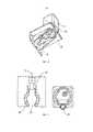
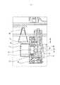
Эта задача решена в системе для приготовления напитка из картриджа, содержащей разливочный аппарат, приемное устройство картриджа и картридж, причем разливочный аппарат содержит держатель картриджа, имеющий по меньшей мере одну направляющую и/или защиту от проворачивания для картриджа и/или приемного устройства картриджа, причем держатель картриджа имеет выемку, которая, по меньшей мере, частично захватывает картридж и/или приемное устройство картриджа, причем приемное устройство картриджа имеет впуск для разбавляющего средства, смесительную камеру, в которой разбавляющее средство смешивается с субстратом напитка и/или пищевого продукта, и выпуск, причем картридж закрыт посредством мембраны, а приемное устройство картриджа имеет прокалыватель для прокалывания мембраны, причем прокалыватель предусмотрен на одной прямой с впуском и выпуском.This problem is solved in a system for preparing a beverage from a cartridge, comprising a dispenser, a cartridge receptacle and a cartridge, wherein the dispenser comprises a cartridge holder having at least one guide and / or anti-rotation protection for the cartridge and / or the cartridge receptacle, wherein the cartridge holder has a recess that at least partially captures the cartridge and / or the cartridge receptacle, the cartridge receptacle having an inlet for a diluent, a mixing chamber in which the diluent is mixed with the beverage and / or food substrate, and an outlet , and the cartridge is closed by means of a membrane, and the cartridge receiving device has a piercer for piercing the membrane, and the piercer is provided in one straight line with the inlet and outlet.
Выполненные для этого предмета настоящего изобретения формы осуществления в равной мере действительны и для других предметов настоящего изобретения, и наоборот.The embodiments made for this subject matter of the present invention are equally valid for other subjects of the present invention, and vice versa.
Настоящее изобретение относится, в частности, к разливочному аппарату с держателем картриджа, в котором устанавливается картридж в разливочном аппарате и который поддерживает и/или направляет его. Картридж имеет полое пространство, в котором находится субстрат напитка и/или пищевого продукта. Этот субстрат, предпочтительным образом, является жидким, и прежде всего концентратом, и для приготовления напитка или пищевого продукта смешивается с растворяющим средством, прежде всего с водой, и затем поступает в сосуд, прежде всего в стакан, который, предпочтительным образом, стоит на расположенной под держателем подставке разливочного аппарата. Субстрат напитка и/или пищевого продукта, предпочтительным образом, содержит жидкую готовую смесь компонентов для прохладительных напитков, таких как содержащие кофеин, углекислый газ, фрукты и/или сахар лимонады и соки, пивные (пивосодержащие) напитки или другие алкогольные и безалкогольные напитки (коктейли).The present invention relates in particular to a filling machine with a cartridge holder, in which the cartridge is mounted in the filling machine and which supports and / or guides it. The cartridge has a hollow space in which the substrate for the beverage and / or food product is located. This substrate is preferably liquid, and especially a concentrate, and for the preparation of a drink or food product is mixed with a dissolving agent, in particular water, and then enters a vessel, in particular a glass, which preferably stands on a disposed under the holder on the base of the filling machine. The substrate of the beverage and / or food product preferably contains a liquid ready-made mixture of components for soft drinks, such as those containing caffeine, carbon dioxide, fruit and / or sugar soft drinks and juices, beer (beer-containing) drinks or other alcoholic and non-alcoholic drinks (cocktails ).
Согласно изобретению теперь на держателе картриджа предусмотрена направляющая и/или защита от проворачивания. В результате этого обеспечивается, что картридж, во-первых, по меньшей мере, в отношении одного направления в пространстве занимает заданное положение относительно разливочного аппарата, во-вторых, предотвращается помещение картриджа до или во время приготовления напитка со смещением или с неверной пространственной ориентацией. За счет этого также обеспечивается, что если картридж снабжен идентификационным кодом продукта, который может быть распознан считывающим устройством разливочного аппарата, то код всегда повернут к считывающему устройству, так чтобы было возможно надежное и безошибочное считывание.According to the invention, a guide and / or anti-rotation protection is now provided on the cartridge holder. As a result, it is ensured that the cartridge, firstly, with respect to at least one direction in space, occupies a predetermined position relative to the dispensing apparatus, and secondly, it is prevented from placing the cartridge before or during the preparation of the beverage with an offset or incorrect spatial orientation. This also ensures that if the cartridge is provided with a product identification code that can be recognized by the reader of the filling machine, the code is always turned towards the reader, so that a reliable and error-free reading is possible.
Предпочтительным образом, держатель картриджа имеет выемку, которая, по меньшей мере, частично захватывает картридж и/или приемное устройство картриджа. Предпочтительным образом, выемка в держателе картриджа и картридж или приемное устройство картриджа, по меньшей мере, частично взаимодействуют с геометрическим соединением и, таким образом, функционируют как опора и/или как защита от проворачивания. Предпочтительным образом, выемка располагается до края, так что контур выемки в одном месте открыт. Там может быть расположена выпуклость в приемном устройстве картриджа.Preferably, the cartridge holder has a recess that at least partially engages the cartridge and / or the cartridge receptacle. Advantageously, the recess in the cartridge holder and the cartridge or cartridge receptacle at least partially cooperate with the geometric connection and thus function as a support and / or as an anti-rotation protection. Preferably, the recess is located up to the edge, so that the contour of the recess is open at one point. There may be a bulge in the cartridge receptacle.
Альтернативным образом, выемка имеет выпуклость для выпуклости на приемном устройстве картриджа. Альтернативно или дополнительно, держатель имеет направляющую, которая взаимодействует с контуром приемного устройства картриджа и/или картриджем. Эта направляющая может, например, представлять собой воротник, который, предпочтительным образом, располагается в пограничной области выемки в держателе. Направляющая, предпочтительным образом, расположена под прямым углом относительно горизонтали и предотвращает опрокидывание картриджа относительно вертикали.Alternatively, the recess has a bulge for a bulge on the cartridge receptacle. Alternatively or additionally, the holder has a guide that engages with the cartridge receiving circuit and / or the cartridge. This guide can, for example, be a collar, which is preferably located in the border region of the recess in the holder. The guide is preferably at right angles to the horizontal and prevents the cartridge from tipping over in relation to the vertical.
Согласно предпочтительной форме осуществления изобретения выемка и/или направляющая имеют отверстие для выступа/выпуклости на приемном устройстве картриджа, которые могут функционировать как защита от проворачивания или как дополнительный стабилизатор.According to a preferred embodiment of the invention, the recess and / or the guide has a protrusion / bulge opening on the cartridge receptacle, which can function as an anti-twist or additional stabilizer.
Предпочтительным образом, держатель имеет разъем для подвода жидкости. Через этот разъем для подвода жидкости подается растворяющее средство для приготовления напитка. Разъем для подвода жидкости держателя, предпочтительным образом, соединен с впускным отверстием для жидкости в приемном устройстве картриджа, прежде всего непроницаемо для жидкости.Preferably, the holder has a fluid inlet. A solvent for preparing a beverage is supplied through this liquid inlet. The liquid supply port of the holder is preferably connected to the liquid inlet in the cartridge receptacle, in particular liquid impermeable.
Согласно еще одной предпочтительной форме осуществления настоящего изобретения предусмотрено, чтобы к разъему для подвода жидкости подводилась жидкость, которую охлаждает холодильный агрегат, причем холодильный агрегат является частью разливочного аппарата или отдельного холодильника, находящегося в связи с разливочным аппаратом. Преимущественным образом, за счет этого прохладительные напитки могут изготавливаться, даже если сам картридж не охлажден и имеет, например, комнатную температуру. Интеграция системы в существующий холодильник имеет то преимущество, что существующий холодильный агрегат холодильника может быть легко эффективным образом совместно использован для разливочного аппарата. Прежде всего, в случае так называемых двухдверных холодильников side-by-side (часто также называемых американскими холодильниками) спереди находится достаточно монтажного пространства для интеграции разливочного аппарата. Возможно, чтобы разливочный аппарат представлял собой комплект дополнительного оборудования для такого холодильника. Холодильный агрегат, предпочтительным образом, содержит компрессорную охладительную установку, абсорбционную охладительную установку или термоэлектрический охладитель. Согласно еще одной предпочтительной форме осуществления настоящего изобретения предусмотрено, чтобы к разъему для подвода жидкости подводилась жидкость, которая при помощи карбонизатора насыщена углекислым газом. Возможно, чтобы карбонизатор являлся частью разливочного аппарата и при этом карбонизатор имел гнездо для патрона с углекислым газом и подающее устройство для насыщения жидкости углекислым газом из патрона с углекислым газом. Преимущественным образом, при помощи системы, таким образом, также могут быть приготовлены насыщенные углекислым газом (прохладительные) напитки. Альтернативным образом, также было бы возможно, чтобы карбонизатор имел внешний разъем для подвода углекислого газа. Жидкость содержит, прежде всего, воду, которая подается из водопровода или емкости с водой разливочного аппарата при помощи одного мембранного насоса или, предпочтительным образом, нескольких мембранных насосов. Подачу воды к разъему для подвода жидкости, предпочтительным образом, контролирует датчик расхода, например ультразвуковой или магнитно-индуктивный датчик расхода.According to a further preferred embodiment of the present invention, it is provided that a liquid is supplied to the liquid supply port, which is cooled by the refrigeration unit, the refrigeration unit being part of a tundish or a separate cooler in connection with the tundish. Advantageously, in this way, soft drinks can be produced even if the cartridge itself is not cooled and is, for example, at room temperature. Integration of the system into an existing refrigerator has the advantage that the existing refrigeration unit of the refrigerator can be easily and efficiently shared with the dispenser. First of all, in the case of so-called side-by-side two-door refrigerators (often also called American refrigerators), there is sufficient installation space at the front to integrate the filling machine. It is possible that the filling machine is a set of additional equipment for such a refrigerator. The refrigeration unit preferably comprises a compressor refrigeration unit, an absorption refrigeration unit, or a thermoelectric cooler. According to a further preferred embodiment of the present invention, it is provided that a liquid is supplied to the liquid supply port, which is saturated with carbon dioxide by means of a carboniser. It is possible that the carbonizer is part of the filling apparatus, and the carbonizer has a seat for a cartridge with carbon dioxide and a feeding device for saturating the liquid with carbon dioxide from the cartridge with carbon dioxide. Advantageously, with the aid of the system, carbon dioxide-rich (soft) drinks can also be prepared. Alternatively, it would also be possible for the carbonator to have an external carbon dioxide connection. The liquid contains, first of all, water, which is supplied from a water main or a water tank of a filling machine by means of one membrane pump or, preferably, several membrane pumps. The water supply to the liquid inlet is preferably controlled by a flow sensor such as an ultrasonic or magnetic inductive flow sensor.
Согласно еще одной предпочтительной форме осуществления настоящего изобретения предусмотрено, чтобы держатель имел соединенное с источником сжатого воздуха выпускное отверстие сжатого воздуха. Выпускное отверстие сжатого воздуха функционирует как устройство для опорожнения картриджа и служит для того, чтобы впускать сжатый воздух снаружи в полое пространство картриджа, чтобы при помощи него выдавить субстрат пищевого продукта и/или напитка из полого пространства смесительной камеры приемного устройства картриджа. Сжатый воздух, прежде всего, подается от разливочного аппарата. Приемное устройство картриджа, предпочтительным образом, имеет впускное отверстие для газа, которое при помещении приемного устройства картриджа в держатель соединяется непосредственно с выпускным отверстием сжатого воздуха держателя. Это имеет преимущество, заключающееся в том, что обратное загрязнение в направлении разливочного аппарата эффективным образом предотвращается, так как напорный канал сразу при помещении картриджной системы в держатель находится под давлением и, таким образом, предотвращается перемещение субстрата пищевого продукта и/или напитка в направлении разливочного аппарата, и прежде всего в направлении источника сжатого воздуха. За счет этого субстрат, выходя из полого пространства в картридже, может перемещаться только в направлении смесительной камеры.According to a further preferred embodiment of the present invention, it is provided that the holder has a compressed air outlet connected to the compressed air source. The compressed air outlet functions as a cartridge emptying device and serves to introduce compressed air from the outside into the hollow space of the cartridge in order to push the food and / or beverage substrate out of the hollow space of the mixing chamber of the cartridge receptacle. Compressed air is primarily supplied from the filling machine. The cartridge receptacle preferably has a gas inlet which, when the cartridge receptacle is placed in the holder, connects directly to the compressed air outlet of the holder. This has the advantage that back-contamination towards the dispenser is effectively prevented, since the pressure channel is pressurized immediately when the cartridge system is placed in the holder and thus the movement of the food and / or beverage substrate towards the dispenser is prevented. apparatus, and above all in the direction of the compressed air source. As a result, the substrate, leaving the hollow space in the cartridge, can only move in the direction of the mixing chamber.
Согласно еще одной предпочтительной форме осуществления настоящего изобретения предусмотрено, чтобы держатель имел активирующий элемент для перемещения прокалывателя приемного устройства картриджа из убранного в выдвинутое положение. Картридж, предпочтительным образом, закрыт посредством мембраны, например уплотняющей пленки. Приемное устройство картриджа, предпочтительным образом, имеет прокалыватель, который является перемещаемым между убранным положением, в котором прокалыватель находится на расстоянии от мембраны, и выдвинутым положением, в котором прокалыватель прокалывает мембрану и выступает в полое пространство. За счет этого картридж вскрывается прокалывателем. Для перемещения прокалывателя в выдвинутое положение держатель имеет активирующий элемент. Возможно, что активирующий элемент содержит жесткий выступ, который при помещении картриджной системы в держатель приходит в соприкосновение с прокалывателем и в результате относительного перемещения между картриджной системой и активирующим элементом перемещает прокалыватель в выдвинутое положение. Особо предпочтительным образом, в прокалыватель интегрировано выпускное отверстие сжатого воздуха.According to a further preferred embodiment of the present invention, it is provided that the holder has an activating element for moving the piercer of the cartridge receptacle from the retracted to the extended position. The cartridge is preferably closed by means of a membrane, for example a sealing film. The cartridge receptacle preferably has a piercer that is movable between a retracted position, in which the piercer is spaced from the membrane, and an extended position, in which the piercer pierces the membrane and protrudes into the cavity. As a result, the cartridge is opened by the lancing device. To move the lancing device to the extended position, the holder has an activating element. It is possible that the activating element comprises a rigid projection which, when the cartridge system is placed in the holder, comes into contact with the lancing device and, as a result of relative movement between the cartridge system and the activating element, moves the lancing device to the extended position. In a particularly preferred manner, a compressed air outlet is integrated into the lancing device.
Предпочтительным образом, держатель содержит крепежный фланец, который с геометрическим и/или силовым замыканием охватывает приемное устройство картриджа во время или после помещения в держатель. Кроме того, крепежный фланец содержит активирующий механизм, который выполнен таким образом, что приведение в действие активирующего механизма приводит к охвату приемного устройства картриджа крепежным фланцем и/или к смещению крепежного фланца таким образом, что создается относительное перемещение между приемным устройством картриджа и находящимся в контакте с прокалывателем активирующим элементом, в результате чего прокалыватель перемещается из убранного положения в выдвинутое положение.Advantageously, the holder comprises a fastening flange which positively and / or positively engages the cartridge receptacle during or after insertion into the holder. In addition, the mounting flange comprises an activating mechanism, which is configured such that actuation of the activation mechanism causes the mounting flange to wrap around the cartridge receptacle and / or displace the mounting flange such that relative movement is created between the cartridge receptacle and the contacting device. with the piercing element activating element, as a result of which the piercing device moves from the retracted position to the extended position.
Активирующий механизм содержит, прежде всего, ручной рычаг для приведения его в действие вручную, причем, предпочтительным образом, ручной рычаг выполнен с возможностью вращения вокруг по существу параллельной продольной оси картриджа оси вращения. Кроме того, активирующий механизм, предпочтительным образом, содержит передаточный механизм, который преобразует вращательное перемещение ручного рычага вокруг параллельной продольной оси оси вращения в по существу параллельное продольной оси поступательное перемещение. После того, как картриджная система была вставлена в держатель, пользователь приводит в действие ручной рычаг, в результате чего картриджная система крепко охватывается и смещается линейно по направлению к активирующему элементу. Благодаря защите от проворачивания и преобразованию вращательного перемещения в линейное поступательное перемещение обеспечивается, что пространственная ориентация картриджа относительно разливочного аппарата остается постоянной. За счет этого преимущественным образом упрощается описанное далее считывание идентификационного кода продукта.The activation mechanism comprises, first of all, a manual lever for manual actuation, the manual lever preferably being rotatable about an axis of rotation which is substantially parallel to the longitudinal axis of the cartridge. In addition, the activation mechanism preferably comprises a transmission mechanism which converts the rotational movement of the hand lever around a longitudinal axis parallel to the axis of rotation into a translational movement substantially parallel to the longitudinal axis. After the cartridge system has been inserted into the holder, the user activates the hand lever so that the cartridge system is firmly gripped and displaced linearly towards the activating element. Thanks to the protection against rotation and the conversion of the rotational movement into linear translational movement, it is ensured that the spatial orientation of the cartridge with respect to the tundish remains constant. This advantageously simplifies the reading of the product identification code described below.
Согласно еще одной предпочтительной форме осуществления настоящего изобретения предусмотрено, чтобы разливочный аппарат имел считывающее устройство для считывания идентификационного кода продукта на картридже и/или приемном устройстве картриджа, причем считывающее устройство расположено, предпочтительным образом, сверху и/или сзади держателя. Предпочтительным образом, идентификационный код продукта встроен в штрихкод, RFID-метку, QR-код, двухмерный матричный штрихкод, цветовой код, голографический код или т. п. Преимущественным образом, так возможно автоматическое считывание идентификационного кода продукта. Считывающее устройство содержит, прежде всего, оптический датчик, такой как, например, ПЗС-камера, который автоматически считывает штрихкод, или QR-код, или двухмерный матричный штрихкод, когда картридж вставляют в машину для приготовления напитка. Альтернативным образом, считывающее устройство содержит передающую и принимающую антенну для автоматического считывания RFID-кода. Альтернативным образом, было бы возможно, чтобы идентификационный код продукта также был встроен в другие компьютерные чипы с возможностью считывания. Понятие QR-код в смысле настоящего изобретения подразумевает, прежде всего, каждый и любой двухмерный матричный штрихкод.According to a further preferred embodiment of the present invention, it is provided that the dispenser has a reader for reading the product identification code on the cartridge and / or the receptacle of the cartridge, the reader being preferably located above and / or behind the holder. Preferably, the product identification code is embedded in a barcode, RFID tag, QR code, 2D matrix barcode, color code, holographic code, or the like. Advantageously, this allows automatic reading of the product identification code. The reader primarily comprises an optical sensor, such as a CCD camera, which automatically reads a barcode, or QR code, or two-dimensional matrix barcode when the cartridge is inserted into the beverage preparation machine. Alternatively, the reader includes a transmitting and receiving antenna for automatically reading the RFID code. Alternatively, it would be possible for the product identification code to also be embedded in other readable computer chips. The term QR code in the sense of the present invention means, first of all, each and every two-dimensional matrix barcode.
В этом отношении понятие QR-код и двухмерный матричный штрихкод используются в качестве синонимов. Альтернативно или дополнительно, было бы также возможно, чтобы идентификационный код продукта содержал штрихкод, точечный код, бинарный код, код Морзе, код на основании шрифта Брайля (шрифт для слепых) или т. п. Код при этом также может быть встроен в трехмерную структуру, такую как, например, рельеф. Идентификационный код продукта содержит, прежде всего, так называемый идентификационный номер продукта, прежде всего универсальный товарный код (UPC), Европейский номер товара (EAN), код GS1, глобальный номер предмета торговли (GTIN) или т.п. За счет этого для этого не требуется вводить новую кодовую систему. Прежде всего, идентификационный код продукта соответствует стандарту GS1. Идентификационный код продукта, предпочтительным образом, напечатан непосредственно на картридже, наклеен на него и/или нанесен на поверхность картриджа, например, при помощи (лазерной) гравировки, штамповки или непосредственно при изготовлении картриджа. Альтернативным образом, также возможно, чтобы картридж был, по меньшей мере, частично покрыт оболочкой, например рукавом, на котором расположен идентификационный код продукта.In this respect, QR code and 2D matrix barcode are used synonymously. Alternatively or additionally, it would also be possible for the product identification code to contain a barcode, a dot code, a binary code, a Morse code, a braille code (font for the blind) or the like. The code can also be embedded in a three-dimensional structure. , such as, for example, relief. The product identification code contains, first of all, the so-called product identification number, especially the Universal Product Code (UPC), the European Article Number (EAN), the GS1 code, the Global Trade Item Number (GTIN) or the like. This does not require the introduction of a new coding system for this. First of all, the product identification code is in accordance with the GS1 standard. The product identification code is preferably printed directly on the cartridge, adhered to it and / or applied to the surface of the cartridge, for example by (laser) engraving, stamping or directly during the manufacture of the cartridge. Alternatively, it is also possible for the cartridge to be at least partially covered by a casing, for example a sleeve, on which the product identification code is located.
Оболочка может быть также склеена или сварена с картриджем. Оболочка или рукав могут быть сделаны из пластиковой пленки, текстиля или бумаги.The casing can also be glued or welded to the cartridge. The sheath or sleeve can be made from plastic sheeting, textiles, or paper.
Еще один или предпочтительный предмет настоящего изобретения - разливочный аппарат, который имеет подставку для сосуда, в котором размещается приготовленный напиток или продукт питания, причем подставка предусмотрена с возможностью изменения высоты расположения и/или с возможностью поворота.Another or preferred aspect of the present invention is a dispenser that has a support for a container in which a prepared beverage or food product is placed, the support being height-adjustable and / or pivotable.
Предпочтительным образом, подставка, например, предусмотрена с возможностью поворота вокруг оси или точки так, что сосуд, прежде всего, при подаче приготовленного напитка или продукта питания, может быть установлен под наклоном. За счет этого можно оказать воздействие на образование пены на поверхности напитка. Подставка может быть перемещена вручную или с приводом от двигателя. Разливочный аппарат может иметь средство, прежде всего камеру, которая определяет состояние пены на поверхности напитка или пищевого продукта и на основании сигнала этого средства наклонное положение соответствующим образом изменяется.Advantageously, the stand is, for example, provided with the possibility of pivoting about an axis or a point so that the container, especially when serving a prepared beverage or food product, can be tilted. This can influence the formation of foam on the surface of the beverage. The stand can be moved manually or driven by a motor. The dispensing apparatus can have means, in particular a chamber, which detects the state of the foam on the surface of the beverage or food product and, based on the signal from this means, the inclined position changes accordingly.
Кроме того, предпочтительным образом, картридж, который используется для приготовления напитка или пищевого продукта, может иметь информацию о наклонном положении, которое следует использовать. Согласно еще одной предпочтительной форме осуществления изобретения картридж имеет код, при помощи которого он может быть идентифицирован. Как только картридж распознан, могут быть получены сведения о желательном наклонном положении сосуда. То же самое действительно в отношении сосуда, в котором размещается напиток или пищевой продукт. На нем также могут иметься сведения и/или код, при помощи которых может быть задано желательное наклонное положение. Кроме того,In addition, in a preferred manner, the cartridge that is used to prepare a beverage or food product can have information about the tilt position to be used. According to a further preferred embodiment of the invention, the cartridge has a code with which it can be identified. Once the cartridge is recognized, the desired tilt position of the vessel can be obtained. The same is true for the receptacle that holds the beverage or food product. It may also contain information and / or a code by means of which the desired tilt position can be set. Besides,
подставка, предпочтительным образом, имеет возможность изменения высоты расположения, так что подставка, например, может быть адаптирована под различный размер стакана и/или имеется возможность воздействия на образование пены за счет длины траектории падения.the stand is advantageously adjustable in height, so that the stand, for example, can be adapted to different sizes of the glass and / or it is possible to influence the formation of foam due to the length of the fall path.
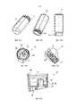
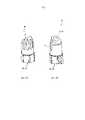
Кроме того, настоящее изобретение относится к системе с приемным устройством картриджа и/или картриджу, причем приемное устройство картриджа, по меньшей мере, частично захватывает картридж с обеих сторон или с одной стороны. Картридж имеет полое пространство, в котором находится субстанция напитка и/или пищевого продукта и которое перед приготовлением напитка и/или пищевого продукта герметично закрыто, прежде всего мембраной. Для приготовления напитка и/или пищевого продукта картридж затем вскрывается, прежде всего прокалывается, мембрана, и субстрат поступает/протекает, прежде всего, при поддержке подаваемого в полое пространство сжатого воздуха в смесительную камеру приемного устройстваFurthermore, the present invention relates to a system with a cartridge receptacle and / or a cartridge, wherein the cartridge receptacle at least partially grips the cartridge from both sides or one side. The cartridge has a hollow space in which the substance of the beverage and / or food product is located and which is hermetically sealed before the preparation of the beverage and / or food product, primarily by a membrane. To prepare a beverage and / or food product, the cartridge is then opened, first of all, the membrane is pierced, and the substrate flows / flows, first of all, with the support of the compressed air supplied into the hollow space into the mixing chamber of the receiving device
картриджа, которая также имеет впуск разбавляющего средства (также называемого растворяющим средством), прежде всего впуск воды, которая смешивается с субстратом, чтобы получить готовый напиток или пищевой продукт, который вытекает наружу из смесительной камеры через также предусмотренный в приемном устройстве картриджа выпуск. Объемный расход растворяющего средства при этом, как правило, существенно больше, чем объемный расход субстрата. Картридж и связанное с картриджем приемное устройство картриджа вместе образуют картриджную систему, которая может быть вставлена в держатель разливочного аппарата.of the cartridge, which also has an inlet for a diluting agent (also called a dissolving agent), in particular an inlet for water, which is mixed with the substrate in order to obtain a finished beverage or food product, which flows out of the mixing chamber through an outlet also provided in the cartridge receptacle. The volumetric flow rate of the dissolving agent is, as a rule, substantially greater than the volumetric flow rate of the substrate. The cartridge and associated cartridge receptacle together form a cartridge system that can be inserted into a dispenser holder.
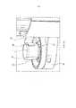
Предпочтительным образом, поперечное сечение потока, то есть поперечное сечение, которое имеется для потока жидкости, прежде всего потока растворяющего средства и/или смеси из растворяющего средства и субстрата, теперь предусмотрено таким образом, что скорость потока растворяющего средства относительно направления потока сначала замедляется и затем снова ускоряется. Ускорение, которое достигается за счет сужения поперечного сечения потока, происходит, по возможности, после того, как растворяющее средство было смешано с субстратом.Advantageously, the flow cross-section, i.e. the cross-section that exists for the liquid flow, in particular the flow of the solvent and / or the mixture of the solvent and the substrate, is now provided in such a way that the flow velocity of the solvent with respect to the direction of flow first slows down and then accelerates again. The acceleration, which is achieved by the narrowing of the flow cross-section, occurs, if possible, after the solvent has been mixed with the substrate.
Согласно еще одному предпочтительному предмету настоящего изобретения смесительная камера имеет выпуклость. Эта выпуклость, предпочтительным образом, выступает за пределы контура, прежде всего бокового контура, который расположен между двумя торцевыми сторонами приемного устройства картриджа. Предпочтительным образом, выпуклость является частью смесительной камеры. Предпочтительным образом, контур смесительной камеры имеет по существу круглую форму, и выгнутость выдается за пределы этого круга.According to another preferred aspect of the present invention, the mixing chamber has a bulge. This bulge preferably protrudes outside the contour, in particular the lateral contour, which is located between the two end sides of the cartridge receptacle. Preferably, the bulge is part of the mixing chamber. Advantageously, the contour of the mixing chamber is substantially circular and the bulge extends beyond this circle.
Согласно одной особо предпочтительной форме осуществления настоящего изобретения в выпуклости предусмотрен выпуск для приготовленного напитка или пищевого продукта. Согласно еще одному предпочтительному предмету настоящего изобретения приемное устройство картриджа имеет фиксирующее и/или предохранительное кольцо. Это фиксирующее и/или предохранительное кольцо, предпочтительным образом, захватывает картридж, который закреплен в приемном устройстве картриджа.According to one particularly preferred embodiment of the present invention, an outlet for a prepared beverage or food product is provided in the bulge. According to another preferred aspect of the present invention, the cartridge receptacle has a retaining and / or retaining ring. This retaining and / or securing ring preferably grips the cartridge, which is secured in the cartridge receptacle.
Предпочтительным образом, на смесительной камере предусмотрено фиксирующее и/или предохранительное кольцо с заданным местом разрушения и/или деформации. До приготовления напитка или продукта питания это место разрушается и/или деформируется, прежде всего необратимо деформируется. Это может осуществляться, например, в результате перемещения картриджа и приемного устройства картриджа друг относительно друга. В результате деформации и/или разрушения приемное устройство картриджа может использоваться только один раз и/или соединение между приемным устройством картриджа и картриджем больше не может быть разобщено.Preferably, a locking and / or safety ring is provided on the mixing chamber with a predetermined break and / or deformation point. Before the preparation of a drink or food product, this place is destroyed and / or deformed, especially irreversibly deformed. This can be done, for example, by moving the cartridge and the cartridge receptacle relative to each other. As a result of deformation and / or destruction, the cartridge receptacle can only be used once and / or the connection between the cartridge receptacle and the cartridge can no longer be disconnected.
Предпочтительным образом, в смесительной камере предусмотрен по меньшей мере один смесительный элемент, который обеспечивает турбулизацию растворяющего средства или смеси растворяющего средства и субстрата.Advantageously, at least one mixing element is provided in the mixing chamber, which turbulizes the dissolving agent or the mixture of the solvent and substrate.
Предпочтительным образом, смесительный элемент предусмотрен как выпуклость и/или дополнительная форма на дне смесительной камеры. Предпочтительным образом, смесительный элемент выполнен таким образом, что углекислый газ, который растворен в растворяющем средстве, не выделяется или выделяется в незначительной степени.Advantageously, the mixing element is provided as a bulge and / or additional shape at the bottom of the mixing chamber. Advantageously, the mixing element is designed in such a way that the carbon dioxide which is dissolved in the dissolving agent is not emitted or emitted to an insignificant extent.
Предпочтительным образом, смесительный элемент выполнен таким образом, что он имеет только небольшую потерю давления. Предпочтительным образом, приемное устройство картриджа имеет прокалыватель, который прокалывает мембрану перед приготовлением напитка или пищевого продукта. Этот прокалыватель выполнен, например, как шип, который торчит из дна смесительной камеры. Приемное устройство картриджа, предпочтительным образом, имеет направляющую шипа, в которой прокалыватель установлен с возможностью смещения. Прокалыватель, за счет этого является перемещаемым между убранным положением, в котором прокалыватель находится на расстоянии от мембраны, и выдвинутым положением, в котором прокалыватель прокалывает мембрану и выступает в полое пространство картриджа.Advantageously, the mixing element is designed in such a way that it only has a small pressure loss. Preferably, the cartridge receptacle has a piercer that pierces the membrane prior to preparation of a beverage or food product. This piercer is designed, for example, as a spike that protrudes from the bottom of the mixing chamber. The cartridge receptacle preferably has a pin guide in which the piercer is movably mounted. The lancing device is thereby movable between a retracted position, in which the lancing device is located at a distance from the membrane, and an extended position, in which the lancing device pierces the membrane and protrudes into the cavity of the cartridge.
Предпочтительным образом, прокалыватель по своему внешнему контуру имеет по меньшей мере одну вогнутость и/или выпуклость, предпочтительным образом несколько вогнутостей и/или выпуклостей, которые служат в качестве выпуска для субстрата. Количество и величина вогнутостей и/или выпуклостей, предпочтительным образом, зависит от вязкости субстрата. Внешняя стенка прокалывателя также снабжена по меньшей мере одним боковым каналом для подачи субстрата в направлении смесительной камеры, когда мембрана проколота. По выполненному сбоку в прокалывателе боковому каналу субстрат затем может протекать мимо мембраны в направлении смесительной камеры.Preferably, the perforator has at least one concavity and / or bulge along its outer contour, preferably several concavities and / or bulges, which serve as an outlet for the substrate. The number and size of concavities and / or bulges preferably depends on the viscosity of the substrate. The outer wall of the lancing device is also provided with at least one lateral channel for feeding the substrate towards the mixing chamber when the membrane is punctured. The substrate can then flow past the membrane in the direction of the mixing chamber via a lateral channel formed on the side of the piercer.
Предпочтительным образом, в прокалывателе выполнено множество боковых каналов. Боковые каналы, прежде всего, выполнены, соответственно, в форме открытого с одной стороны паза. Возможно, чтобы поперечное сечение боковых каналов и/или количество боковых каналов было адаптировано к вязкости субстрата, так чтобы боковые каналы контролировали или же ограничивали поток субстрата в направлении смесительной камеры. При высокой вязкости используется большее количество боковых каналов или боковые каналы с большим поперечным сечением, в то время как при низкой вязкости предусмотрено меньшее количество боковых каналов или боковые каналы с меньшим поперечным сечением. За счет этого для каждого картриджа существует подходящее приемное устройство картриджа.Preferably, a plurality of side channels are provided in the piercer. The side channels are in particular designed in the form of a groove open on one side. It is possible for the cross-section of the side channels and / or the number of side channels to be adapted to the viscosity of the substrate, so that the side channels control or otherwise restrict the flow of the substrate towards the mixing chamber. At high viscosities, more side channels or side channels with a larger cross section are used, while at low viscosities there are fewer side channels or side channels with a smaller cross section. As a result, there is a suitable cartridge receptacle for each cartridge.
Предпочтительным образом, в прокалыватель интегрирована магистраль подачи сжатого воздуха, прежде всего в форме внутреннего канала, причем на обращенной от картриджа стороне прокалывателя выполнен доступный, прежде всего, снаружи приемного устройства картриджа разъем для подвода сжатого воздуха магистрали подачи сжатого воздуха для соединения с источником сжатого воздуха, и при этом на обращенной к полому пространству картриджа стороне прокалывателя выполнен вывод сжатого воздуха магистрали подачи сжатого воздуха для вдувания сжатого воздуха в картридж.Advantageously, a compressed air supply line is integrated into the lancing device, in particular in the form of an internal channel, and on the side of the lancing device facing away from the cartridge there is provided a connection for the compressed air supply of the compressed air supply line for connection to a compressed air source, which is accessible primarily from the outside of the cartridge receptacle. , and at the same time on the side of the piercer facing the hollow space of the cartridge, the outlet of compressed air of the compressed air supply line for blowing compressed air into the cartridge is made.
Предпочтительным образом, уже при помещении картриджной системы, собранной из картриджа и приемного устройства картриджа, в держатель к разъему для подвода сжатого воздуха уже подается сжатый воздух, чтобы предотвратить возможное обратное загрязнение. Альтернативным образом, прокалыватель под действием подаваемого через разливочный аппарат сжатого воздуха перемещается из убранного положения в выдвинутое положение. Вместо сжатого воздуха в полое пространство также может быть введен углекислый газ, чтобы перевести субстрат из полого пространства в смесительную камеру.Advantageously, already when placing the cartridge system assembled from the cartridge and the cartridge receptacle, compressed air is already supplied to the holder at the compressed air connection in order to prevent possible back-contamination. Alternatively, the piercer is moved from the retracted position to the extended position by the compressed air supplied through the tundish. Instead of compressed air, carbon dioxide can also be introduced into the cavity to transfer the substrate from the cavity to the mixing chamber.
Предпочтительным образом, прокалыватель также имеет канал, который заканчивается на заостренном конце или в области заостренного конца. Через этот канал в картридж может вдуваться газ, прежде всего воздух или углекислый газ, чтобы ускорить и/или дозировать подачу субстрата.Preferably, the lancing device also has a channel that ends at the pointed end or in the region of the pointed end. A gas, in particular air or carbon dioxide, can be injected into the cartridge through this channel in order to accelerate and / or dose the supply of the substrate.
Система, предпочтительным образом, выполнена так, что соединение разъема для подвода сжатого воздуха с выпускным отверстием сжатого воздуха держателя происходит, когда приемное устройство картриджа вставлено в держатель и/или приводится в действие активирующий механизм для крепежного фланца. За счет этого магистраль подачи сжатого воздуха помещается под давление как можно раньше, так что предотвращается обратное загрязнение разливочного аппарата субстратом.The system is preferably configured such that the connection of the compressed air connector to the compressed air outlet of the holder occurs when the cartridge receptacle is inserted into the holder and / or an actuating mechanism for the mounting flange is actuated. As a result, the compressed air line is pressurized as early as possible so that substrate contamination of the filling machine is prevented.
Как указано выше, прокалыватель предусмотрен на одной прямой с впуском и выпуском. При этом впуск и выпуск могут быть предусмотрены на противоположных концах приемного устройства картриджа.As indicated above, the lancing device is provided in a straight line with the inlet and outlet. In this case, the inlet and outlet can be provided at opposite ends of the cartridge receptacle.
Согласно еще одному предпочтительному предмету настоящего изобретения выпуск на смесительной камере выполнен подвижно, прежде всего с возможностью поворота, или имеет средство, при помощи которого выпуск может быть ориентирован заданным образом, прежде всего в направлении боковой стенки сосуда, в котором размещается приготовленный напиток или пищевой продукт. Эта форма осуществления имеет преимущество, прежде всего, в случае напитков или пищевых продуктов, которые склонны к образованию пены. Перемещение выпуска может осуществляться вручную или с приводом от двигателя. Для случая, когда картридж имеет идентификацию, поворот может осуществляться автоматически после того, как разливочный аппарат распознает картридж. Кроме того, может иметься средство, которое распознает пену.According to a further preferred aspect of the present invention, the outlet on the mixing chamber is movable, in particular pivotable, or has means by means of which the outlet can be oriented in a predetermined manner, in particular towards the side wall of the container in which the prepared beverage or food product is placed. ... This embodiment is advantageous in particular in the case of beverages or foodstuffs that tend to foam. Displacement of the outlet can be carried out manually or with a drive from the engine. For the case where the cartridge is identified, the rotation can be carried out automatically after the dispenser recognizes the cartridge. In addition, there may be a means that detects foam.
Основываясь на этом анализе, затем может быть выполнена настройка выпуска. Картридж, предпочтительным образом, изготовлен из пластмассы, прежде всего способом прессования и/или выдувного формования. Based on this analysis, release tuning can then be done. The cartridge is preferably made of plastic, in particular by compression and / or blow molding.
Картридж имеет боковую стенку, которая, имеет например, круглое, прямоугольное, квадратное, коническое или овальное поперечное сечение. На конце боковой стенки, как правило, предусмотрено дно, по существу монолитное. Боковая стенка и, при необходимости, донная область очерчивают полое пространство, в котором предусмотрен субстрат напитка и/или пищевого продукта, прежде всего в жидкой форме. На другом конце стенной области предусмотрена соединительная область, при помощи которой картридж соединяется с приемным устройством картриджа. Это приемное устройство картриджа может быть частью разливочного аппарата или быть отдельной от разливочного аппарата деталью.The cartridge has a side wall that, for example, has a circular, rectangular, square, conical or oval cross-section. At the end of the side wall, as a rule, a bottom is provided which is substantially monolithic. The side wall and, if appropriate, the bottom region outline a hollow space in which the substrate for the beverage and / or food product is provided, especially in liquid form. At the other end of the wall region, a connecting region is provided by which the cartridge is connected to the cartridge receptacle. This cartridge receptacle may be part of the dispenser or be a separate part from the dispenser.
Предпочтительным образом, соединительная область предусмотрена таким образом, что она имеет по меньшей мере один фланец. Фланец выдается из соединительной области и, предпочтительным образом, отстоит от стенной области соединительной области под углом, особо предпочтительным образом под прямым углом. Для приготовления напитка или пищевого продукта фланец, предпочтительным образом, расположен горизонтально.Preferably, the connecting area is provided in such a way that it has at least one flange. The flange protrudes from the connecting region and is preferably spaced from the wall region of the connecting region at an angle, particularly preferably at right angles. For the preparation of a beverage or food product, the flange is preferably located horizontally.
Предпочтительным образом, фланец выполнен из цельного материала, то есть не является полым.Advantageously, the flange is made of a solid material, that is, it is not hollow.
Прежде всего, фланец отлит под давлением.First of all, the flange is injection molded.
Кроме того, предпочтительным образом, фланец снабжен позиционирующим средством и/или покровным средством. Позиционирующее средство обеспечивает, что картридж может быть расположен в разливочном аппарате и/или приемном устройстве картриджа только в заданном положении, прежде всего под заданным углом поворота, прежде всего относительно продольной центральной оси картриджа. Покровное средство закрывает область, прежде всего область, через которую протекает приготовленный напиток или пищевой продукт. Предпочтительным образом, позиционирующее средство и покровное средство идентичны.In addition, in a preferred manner, the flange is provided with positioning means and / or covering means. The positioning means ensures that the cartridge can only be positioned in the filling apparatus and / or the cartridge receptacle in a predetermined position, in particular at a predetermined angle of rotation, in particular with respect to the longitudinal central axis of the cartridge. The coating agent covers the area, especially the area through which the prepared beverage or food product flows. Preferably, the positioning means and the coating means are identical.
Предпочтительным образом, позиционирующее средство и/или покровное средство является вогнутостью и/или выпуклостью, которая выдается из фланца, прежде всего из его контура.Advantageously, the positioning means and / or the covering means is a concavity and / or a convexity that protrudes from the flange, in particular from its contour.
Предпочтительным образом, позиционирующее средство и/или покровное средство предусмотрены как единое целое с фланцем. Например, позиционирующее средство и/или покровное средство выполнены как носик, который с одной стороны приформован к контуру фланца. Толщина позиционирующего средства и/или покровного средства при этом по меньшей мере по существу соответствует толщине фланца.Advantageously, the positioning means and / or the covering means are provided integrally with the flange. For example, the positioning means and / or the covering means are designed as a spout, which on one side is molded to the contour of the flange. The thickness of the positioning means and / or the covering means in this case at least substantially corresponds to the thickness of the flange.
Согласно предпочтительной форме осуществления между стенной областью и соединительной областью предусмотрена шейка. Эта шейка может иметь, например, круглое поперечное сечение. Шейка представляет собой стенную область соединительной области. Фланец, предпочтительным образом, примыкает к шейке под прямым углом.According to a preferred embodiment, a neck is provided between the wall region and the connecting region. This neck can have, for example, a circular cross-section. The neck is the wall area of the connective area. The flange is preferably at right angles to the neck.
Предпочтительным образом, мембрана, которая, прежде всего, герметично закрывает картридж до его использования, предусмотрена на фланце, прежде всего на его торцевой поверхности, прежде всего присоединена к нему термосваркой. Для этого фланец, прежде всего его торцевая поверхность, может иметь утолщение, прежде всего кольцеобразное утолщение, которое при термосварке взаимодействует со сварочным инструментом. Предпочтительным образом, внешний контур мембраны меньше, чем внешний контур фланца. Предпочтительным образом, в стенной области и/или в области шейки предусмотрено фиксирующее средство. При помощи этого фиксирующего средства картридж может быть соединен с разливочным аппаратом.Advantageously, a membrane, which primarily seals the cartridge hermetically before use, is provided on the flange, in particular at its end surface, and is first of all heat-welded thereto. For this, the flange, especially its end surface, can have a bulge, in particular an annular bulge, which interacts with the welding tool during heat sealing. Advantageously, the outer contour of the diaphragm is smaller than the outer contour of the flange. Preferably, a fixing means is provided in the wall region and / or in the neck region. With this fixing means, the cartridge can be connected to the filling machine.
Фиксирующее средство может представлять собой, например, паз, который входит в зацепление в фиксирующее средство на разливочном аппарате. Приемное устройство картриджа может быть жестко соединено с картриджем или быть сменной деталью, которая после использования картриджа отделяется от него и соединяется с новым картриджем. The locking means can be, for example, a groove that engages with the locking means on the tundish. The receptacle of the cartridge can be rigidly connected to the cartridge or be a replaceable part, which after use of the cartridge is separated from it and connected to a new cartridge.
Предпочтительным образом, приемное устройство картриджа изготовлено из пластмассы, прежде всего способом литья под давлением. Предпочтительным образом, приемное устройство картриджа соединено с разливочным аппаратом. Предпочтительным образом, покровное средство, которое предусмотрено на фланце картриджа, покрывает выпуск приемного устройства картриджа.Advantageously, the cartridge receptacle is made of plastic, in particular by injection molding. Advantageously, the cartridge receptacle is connected to the dispenser. Advantageously, the cover means, which is provided on the cartridge flange, covers the outlet of the cartridge receptacle.
Предпочтительным образом, фланец на картридже, прежде всего его контур, взаимодействует с приемным устройством картриджа уплотняющим образом. Для этого контур фланца может, например, входить в зацепление в паз в приемном устройстве картриджа. Это соединение фланец/паз также может служить силовым замыканием, чтобы предотвратить смещение картриджаAdvantageously, the flange on the cartridge, especially its contour, interacts with the cartridge receptacle in a sealing manner. For this, the contour of the flange can, for example, engage in a groove in the cartridge receptacle. This flange / groove connection can also be used as a force lock to prevent displacement of the cartridge.
относительно приемного устройства картриджа во время приготовления напитка или пищевого продукта и разуплотнение соединения между картриджем и приемным устройством картриджа. Согласно еще одной предпочтительной форме осуществления картридж и приемное устройство картриджа, прежде всего, перед прокалыванием мембраны предусмотрены с продольным смещением друг относительно друга. За счет этого продольного смещения прокалыватель затем может входить в контакт с мембраной и прокалывать ее.relative to the cartridge receptacle during the preparation of a beverage or food product, and loosening the connection between the cartridge and the cartridge receptacle. According to a further preferred embodiment, the cartridge and the cartridge receptacle are provided, in particular, longitudinally offset relative to each other before piercing the membrane. Due to this longitudinal displacement, the piercer can then come into contact with the membrane and pierce it.
Предпочтительным образом, картридж и приемное устройство картриджа соединены друг с другом без возможности поворота.Advantageously, the cartridge and the cartridge receptacle are rotatably coupled to each other.
Предпочтительным образом, прокалыватель имеет канал. Через этот канал в картридж под давлением может поступать газ, который выдавливает субстрат напитка и/или пищевого продукта из картриджа, прежде всего в смесительную камеру приемного устройства картриджа.Preferably, the lancing device has a channel. Through this channel, a gas can enter the cartridge under pressure, which forces the beverage and / or food substrate out of the cartridge, in particular into the mixing chamber of the cartridge receptacle.
Еще одним предметом настоящего изобретения является способ приготовления напитка при помощи предлагаемой системы, отличающийся следующими шагами: - помещение собранной из картриджа и приемного устройства картриджа картриджной системы в держатель,Another object of the present invention is a method for preparing a beverage using the proposed system, characterized by the following steps: - placing the cartridge system assembled from the cartridge and the cartridge receiver into the holder,
- создание гидродинамического соединения между источником жидкости разливочного аппарата и впуском приемного устройства картриджа, - creation of a hydrodynamic connection between the liquid source of the pouring apparatus and the inlet of the cartridge receiving device,
- создание соединения сжатого воздуха между источником сжатого воздуха разливочного аппарата и разъемом для подвода сжатого воздуха приемного- creation of a compressed air connection between the compressed air source of the casting apparatus and the connector for the supply of compressed air of the receiving
устройства картриджа, device cartridge,
- прокалывание мембраны за счет перемещения прокалывателя из убранного положения в выдвинутое положение,- piercing the membrane by moving the lancing device from the retracted position to the extended position,
- перемещение субстрата напитка и/или пищевого продукта из картриджа в смесительную камеру путем подачи сжатого воздуха в картридж через разъем- moving the substrate of the drink and / or food product from the cartridge to the mixing chamber by supplying compressed air to the cartridge through the connector
для подвода сжатого воздуха,for compressed air supply,
- подача разжижающего средства в смесительную камеру через впуск и выведение созданного в смесительной камере за счет смешивания субстрата напитка и/или пищевого продукта с разбавляющим средством напитка посредством выпуска.- supply of the diluent to the mixing chamber through the inlet and outlet of the beverage created in the mixing chamber by mixing the substrate and / or food product with the beverage diluent by means of the outlet.
Предпочтительным образом, разжижающее средство перед подачей во впуск охлаждается и/или насыщается углекислым газом.Advantageously, the fluidizing agent is cooled and / or saturated with carbon dioxide before being introduced into the inlet.
Согласно одной предпочтительной форме осуществления настоящего изобретения предусмотрено, чтобы прокалыватель перемещался активирующим элементом разливочного аппарата из убранного положения в выдвинутое положение, причем приемное устройство картриджа, предпочтительным образом, так перемещалось относительно стационарного активирующего элемента, чтобы прокалыватель перемещался из убранного положения в выдвинутое положение. В результате перемещения прокалывателя в выдвинутое положение прокалывается мембрана, и, таким образом, вскрывается картридж. Стационарный активирующий элемент должен только перемещать картриджную систему относительно держателя.According to one preferred embodiment of the present invention, provision is made for the piercer to be moved by the activation element of the dispenser from the retracted position to the extended position, the cartridge receptacle preferably being moved relative to the stationary activation element so that the piercer is moved from the retracted position to the extended position. Moving the lancing device to the extended position punctures the membrane and thus exposes the cartridge. The stationary activating element only needs to move the cartridge system relative to the holder.
Согласно еще одной предпочтительной форме осуществления настоящего изобретения предусмотрено, чтобы во время или после помещения картриджнойAccording to a further preferred embodiment of the present invention, it is provided that during or after the placement of the cartridge
системы в держатель крепежный фланец держателя приводился в перемещение приводимым в действие вручную или с приводом от двигателя активирующим механизмом таким образом, что крепежный фланец с геометрическим и/или силовым замыканием охватывает приемное устройство картриджа и/или что крепежный фланец перемещается таким образом, что между приемным устройством картриджа и находящимся в контакте с прокалывателем активирующим элементом создается относительное перемещение, за счет чего прокалыватель перемещался из убранного положения в выдвинутое положение. Возможно, чтобы крепежный фланец содержал захваты с возможностью сближения, которые при помощи активирующего механизма приближаются друг к другу и, таким образом, зажимают приемное устройство картриджа между собой. Затем или одновременно крепежный фланец перемещается относительно стационарного активирующего элемента для перемещения прокалывателя во внутренней области приемного устройство картриджа относительно мембраны картриджа.system into the holder, the mounting flange of the holder was moved by a manually or motor-driven activation mechanism in such a way that the mounting flange positively and / or forcibly encloses the cartridge receptacle and / or that the mounting flange moves in such a way that between the receiving the device of the cartridge and the activating element in contact with the piercer creates a relative movement, due to which the piercer moves from the retracted position to the extended position. It is possible for the fastening flange to comprise converging grips which, by means of an activating mechanism, approach each other and thus clamp the cartridge receptacle together. Then, or simultaneously, the mounting flange is moved relative to the stationary activating element to move the piercer in the inner region of the cartridge receptacle relative to the cartridge membrane.
Предпочтительным образом, активирующий механизм приводится в действие поворотом ручного рычага вручную вокруг по существу параллельной продольной оси картриджа оси вращения. Активирующий механизм при этом при помощи передаточного механизма преобразует вращательное перемещение ручного рычага вокруг параллельной продольной оси оси вращения в по существу параллельное продольной оси поступательное перемещение, в результате чего крепежный фланец перемещается в направлении активирующего элемента. Это имеет то преимущество, что ориентация картриджа вокруг его продольной оси остается постоянной, так что, прежде всего, положение идентификационного кода продукта относительно считывающего устройства не изменяется.Advantageously, the activation mechanism is actuated by manually rotating the hand lever about an axis of rotation which is substantially parallel to the longitudinal axis of the cartridge. In this case, the activating mechanism, by means of the transmission mechanism, converts the rotational movement of the hand lever around the axis of rotation parallel to the longitudinal axis into a translational movement which is substantially parallel to the longitudinal axis, as a result of which the fastening flange moves in the direction of the activating element. This has the advantage that the orientation of the cartridge about its longitudinal axis remains constant, so that, above all, the position of the product identification code relative to the reader does not change.
Согласно еще одной предпочтительной форме осуществления настоящего изобретения предусмотрено, что по времени до, во время или после помещения картриджной системы в держатель и/или подачи сжатого воздуха в картридж и/или подачи разбавляющего средства в смесительную камеру и/или перемещения крепежного фланца относительно активирующего элемента считывающее устройство считывает идентификационный код продукта. Считанный идентификационный код продукта, предпочтительным образом, оценивается анализатором, причем подача сжатого воздуха и/или разбавляющего средства и/или перемещение крепежного фланца относительно активирующего элемента происходит только тогда, когда идентификационный код продукта может быть подтвержден анализатором. За счет этого обеспечивается, что разливочный аппарат может быть введен в действие только с известной или сертифицированной для разливочного аппарата картриджной системой, так чтобы предотвратить повреждение разливочного аппарата или опасность травмирования пользователя из-за ошибочного использования неверной картриджной системы, которая, например, не может выдерживать данное давление.According to a further preferred embodiment of the present invention, it is provided that in time before, during or after placing the cartridge system in the holder and / or supplying compressed air to the cartridge and / or supplying the diluting agent to the mixing chamber and / or moving the fastening flange relative to the activating element the reader reads the product identification code. The read product identification code is advantageously evaluated by the analyzer, wherein the supply of compressed air and / or diluent and / or movement of the mounting flange relative to the activating element occurs only when the product identification code can be confirmed by the analyzer. This ensures that the dispenser can only be operated with a cartridge system known or certified for the dispenser, so as to prevent damage to the dispenser or the risk of injury to the user due to the erroneous use of an incorrect cartridge system, which, for example, cannot withstand given pressure.
Возможно, чтобы свойства подаваемого разбавляющего средства, и прежде всего временная характеристика объемного расхода, общий объем, давление, паузы при подаче, температура и/или насыщение углекислым газом подаваемого разбавляющего средства, регулировались в зависимости от подтвержденного идентификационного кода продукта. Альтернативно или дополнительно, также регулируются свойства подаваемого сжатого воздуха, и прежде всего временная характеристика объемного расхода, общий объем, паузы при подаче и/или давление подаваемого сжатого воздуха, в зависимости от подтвержденного идентификационного кода продукта.It is possible that the properties of the supplied diluent, and above all the time characteristic of the volumetric flow rate, total volume, pressure, pauses during the supply, temperature and / or carbon dioxide saturation of the supplied diluent, are controlled depending on the verified product identification code. Alternatively or additionally, the properties of the supplied compressed air, and in particular the time characteristic of the volumetric flow rate, the total volume, the supply pauses and / or the pressure of the supplied compressed air, are also controlled, depending on the verified product identification code.
Предпочтительным образом, также регулируется зависимость между объемным расходом разбавляющего средства и объемным расходом сжатого воздуха в зависимости от подтвержденного идентификационного кода продукта. В идентификационном коде продукта заложены, прежде всего, все без исключения параметры и/или регулируемые разливочным аппаратом переменные процесса приготовления напитка, так что разливочный аппарат получает от картриджа абсолютно все сведения, которые необходимы или, по меньшей мере, полезны для приготовления соответствующего напитка. Возможно также, чтобы эти сведения хранились во внутреннем запоминающем устройстве разливочного аппарата и при помощи идентификационного кода продукта выводились для соответствующего картриджа и использовались для управления последующим процессом приготовления напитка, как только обнаруживается наличие этого картриджа в держателе.Advantageously, the relationship between the volumetric flow rate of the diluting agent and the volumetric flow rate of compressed air is also controlled depending on the verified product identification code. The product identification code contains, first of all, all parameters and / or variables of the beverage preparation process controlled by the filling device, so that the filling device receives from the cartridge absolutely all information that is necessary or at least useful for the preparation of the corresponding beverage. It is also possible for this information to be stored in the internal memory of the filling machine and, by means of the product identification code, displayed for the respective cartridge and used to control the subsequent preparation of the beverage as soon as the presence of this cartridge in the holder is detected.
Еще один предмет настоящего изобретения или еще одна предпочтительная форма осуществления способа - это некий или определенный вышеназванный способ приготовления напитка или пищевого продукта, при котором для регулирования количества пены на поверхности напитка или пищевого продукта контролируется или регулируется объемный расход растворяющего средства, прежде всего воды.Another aspect of the present invention, or another preferred embodiment of the method, is a certain or certain of the aforementioned method for preparing a beverage or food product, in which the volumetric flow rate of the dissolving agent, especially water, is controlled or regulated to control the amount of foam on the surface of the beverage or food product.
Выполненные для этого предмета настоящего изобретения формы осуществления в равной мере действительны и для других предметов настоящего изобретения, и наоборот.The embodiments made for this subject matter of the present invention are equally valid for other subjects of the present invention, and vice versa.
Согласно изобретению объемный расход контролируется или регулируется, чтобы повлиять на количество пены на поверхности напитка или пищевого продукта. Например, на количество пены, прежде всего, измеряемое как высота пены, можно повлиять таким образом, чтобы во время приготовления напитка или пищевого продукта образовывалось больше или меньше пены.According to the invention, the volumetric flow rate is controlled or regulated to influence the amount of foam on the surface of the beverage or food product. For example, the amount of foam, primarily measured as the height of the foam, can be influenced so that more or less foam is generated during the preparation of a beverage or food product.
Альтернативно или дополнительно, можно менять качество пены путем регулирования или нормирования объемного расхода растворяющего средства. Прежде всего, в средстве могут создаваться маленькие пузырьки и, таким образом, более стабильная пена или более крупные пузырьки и, таким образом, более нестабильная пена.Alternatively or additionally, you can change the quality of the foam by adjusting or rationing the volumetric flow rate of the solvent. First of all, small bubbles can be created in the agent and thus more stable foam or larger bubbles and thus more unstable foam.
Предпочтительным образом, предусмотрено средство, которое фиксирует по меньшей мере один параметр пены, например ее высоту. На основании сигнала этого средства затем контролируется или регулируется объемный расход растворяющего средства. Например, средство представляет собой камеру.Advantageously, a means is provided which fixes at least one parameter of the foam, for example its height. Based on the signal from this agent, the volumetric flow rate of the dissolving agent is then monitored or adjusted. For example, the facility is a camera.
Альтернативно или дополнительно, может быть также задана определенная для соответствующего субстрата кривая расхода.Alternatively or additionally, a flow curve defined for the respective substrate can also be defined.
Например, растворяющее средство периодически самостоятельно дозируется, прежде всего, в смесительную камеру или картридж. В смесительной камере или же в картридже растворяющее средство смешивается с субстратом.For example, the dissolving agent is periodically self-metered, especially into the mixing chamber or cartridge. In the mixing chamber or in the cartridge, the solvent is mixed with the substrate.
Согласно предпочтительной форме осуществления настоящего изобретения субстрат дозируется в картридже пропорционально или непропорционально объемному расходу растворяющего средства.According to a preferred embodiment of the present invention, the substrate is metered in the cartridge in proportion or disproportionate to the volumetric flow rate of the solvent.
Еще одна предлагаемая или предпочтительная форма осуществления настоящего изобретения относится к способу, при котором для влияния не высоту пены на поверхности напитка или пищевого продукта изменяется наклон сосуда, в котором размещается напиток или пищевой продукт.Another proposed or preferred embodiment of the present invention relates to a method in which the slope of the container in which the beverage or food is placed is changed to influence the height of the foam on the surface of the beverage or food product.
Выполненные для этого предмета настоящего изобретения формы осуществления в равной мере действительны и для других предметов настоящего изобретения, и наоборот.The embodiments made for this subject matter of the present invention are equally valid for other subjects of the present invention, and vice versa.
Предпочтительным образом, наклон контролируется и/или регулируется как функция времени и/или состояния заполнения сосуда.Preferably, the slope is controlled and / or regulated as a function of time and / or the filling state of the vessel.
Описание фигурDescription of figures
Далее изобретение поясняется на основании фиг. 1-5. Эти пояснения приведены исключительно в качестве примера и не ограничивают общий замысел согласно изобретению. Пояснения действительны в равной степени для предлагаемого в изобретении картриджа и для предлагаемой в изобретении системы.The invention is further explained on the basis of FIG. 1-5. These explanations are given by way of example only and do not limit the general concept according to the invention. The explanations apply equally to the cartridge according to the invention and to the system according to the invention.
Фиг. 1 показывает картридж и приемное устройство картриджа системы согласно первой форме осуществления настоящего изобретения. FIG. 1 shows a cartridge and a cartridge receiver of a system according to a first embodiment of the present invention.
Фиг. 2-5 показывают разливочный аппарат и систему согласно первой форме осуществления настоящего изобретения.FIG. 2-5 show a dispenser and system according to a first embodiment of the present invention.
Фиг. 6А - 6В показывают картридж системы согласно второй формеFIG. 6A-6B show a system cartridge according to a second form.
осуществления настоящего изобретения.implementation of the present invention.
Фиг. 7А и 7Б показывают приемное устройство картриджа системы согласно второй форме осуществления настоящего изобретения.FIG. 7A and 7B show a cartridge receiver of a system according to a second embodiment of the present invention.
Фиг. 8А и 8Б показывают прокалыватель приемного устройства картриджа системы согласно второй форме осуществления настоящего изобретения.FIG. 8A and 8B show a cartridge receiver piercer of a system according to a second embodiment of the present invention.
Фиг. 9А и 9Б показывают разливочный аппарат и систему согласно третьей форме осуществления настоящего изобретения. FIG. 9A and 9B show a dispenser and system according to a third embodiment of the present invention.
На фиг. 1 показана картриджная система, которая состоит из картриджа 1, а также приемного устройства 10 картриджа. Картридж 1, предпочтительным образом, изготовлен из пластмассы, например, способом напыления, или литья под давлением, или выдувного формования. Картридж 1 имеет, в данном случае, квадратную стенную область 6, к одному, здесь верхнему, концу которой прилегает донная область 7. Стенная область 6 и донная область 7 ограничивают полое пространство, в котором находится субстрат напитка и/или пищевого продукта, прежде всего концентрат, при помощи которого может быть изготовлен напиток или пищевой продукт. На противоположном донной области 7 конце, здесь на нижнем конце стенной области 6 предусмотрена соединительная область 4, которая, в данном случае, имеет шейку 3, а также фланец 5. Полое пространство картриджа 1 после его заполнения герметично закрывается покровным элементом, здесь мембраной 14. Мембрана 14, прежде всего пластиковая пленка, предпочтительным образом, неразъемно, прежде всего при помощи термосварки, соединена с фланцем 5. При помощи соединительной области 4 картридж 1 соединен с приемным устройством 10 картриджа. На фланце 5 дополнительно предусмотрено позиционирующее и/или покровное средство 8, которое, в данном случае, предусмотрено как выпуклость, прежде всего как выпуклость в форме носика. Носик монолитно приформован к фланцу 5. Кроме того, картриджная система имеет приемное устройство 10 картриджа. Приемное устройство 10 картриджа имеет впуск 15 для разбавляющего средства (также называемого растворяющим средством), которое, предпочтительным образом, содержит воду, а также смесительную камеру 13, в которой разбавляющее средство и субстрат напитка и/или пищевого продукта смешиваются друг с другом. Направление потока смеси показано стрелкой 12. Готовый напиток/пищевой продукт покидает смесительную камеру 13 через выпуск 11 и поступает в сосуд (не показан), например в стакан для напитка. Кроме того, приемное устройство 10 картриджа имеет прокалыватель 16, здесь шип, который прокалывает мембрану 14, которая присоединена термосваркой к области фланца 5 картриджа 1, так что субстрат напитка или пищевого продукта может протекать в смесительную камеру 13, прежде всего, вдоль внешней поверхности шипа, который для этого, предпочтительным образом, на своей внешней стороне имеет боковые каналы 17.FIG. 1 shows a cartridge system which consists of a
Чтобы проколоть мембрану 14, картридж 1 и/или приемное устройство 10 картриджа перемещаются относительно, а также вдоль друг друга, чтобы шип 16 прошел через мембрану 14. Альтернативным образом, шип 16 расположен в направляющей 28 шипа приемного устройства 10 картриджа с возможностью продольного смещения, так что относительное перемещение между приемным устройством 10 картриджа и картриджем 1 не требуется, а только шип 16 перемещается из убранного положения, в котором он находится на расстоянии от мембраны 14 (смотри фиг. 1), в выдвинутое положение, в котором он прокалывает мембрану 14 и выступает в полое пространство картриджа.To pierce the
Поток субстрата в смесительную камеру 13 может быть ускорен и целенаправленно отрегулирован при помощи газа, который под давлением подается по каналу 18 в прокалывающем шипе 16 в полое пространство картриджа 1. Например, давление в картридже 1 и, таким образом, объемный расход субстрата могут быть адаптированы к объемному расходу растворяющего средства. Это, прежде всего, может быть интересно в том случае, когда для оказания влияния на пену объемный расход растворяющего средства целенаправленно контролируется или регулируется. Объемный расход субстрата затем, предпочтительным образом, адаптируется к объемному расходу растворяющего средства.The flow of the substrate into the mixing
Предпочтительным образом, фланец 5 картриджа 1 уплотняющим образом взаимодействует с приемным устройством 10 картриджа и, таким образом, обеспечивает, что жидкость покидает смесительную камеру 13 только через 15 выпуск 5. Кроме того, прежде всего, из этих фигур ясно, что выпуклость 8, в данном случае, является не только позиционирующим средством, но и, прежде всего, уплотняющим образом покрывает выпуск 11 в приемном устройстве картриджа. Фланец 5 и предусмотренная на нем выпуклость 8 могут уплотняющим образом взаимодействовать своей торцевой поверхностью и/или своим контуром с соответствующими поверхностями приемного устройства картриджа.Advantageously, the
На фиг. 2-5 показан держатель 24 разливочного аппарата и система согласно первой форме осуществления изобретения. На фиг. 2 держатель 24, в который может быть помещена показанная на фиг. 1 картриджная система, и прежде всего приемное устройство 10 картриджа картриджной системы, показан без картриджной системы. На фиг. 3 и 4 в держатель 24 вставлена картриджная система. На фиг. 5 картриджная система и держатель 24 показаны отдельно друг от друга.FIG. 2-5 show a
Держатель 24 имеет выемку 26, которая, по меньшей мере, частично захватывает приемное устройство 10 картриджа. Прежде всего, на основании фиг. 4 видно, что часть приемного устройства 10 картриджа, которая входит в выемку 26, может взаимодействовать с ней с геометрическим замыканием. Фиг. 2 и 3, кроме того, особо отчетливо показывают, что выемка 26 располагается до края держателя 24, так что там возникает отверстие, в которое входит выпуск 11 смесительной камеры 13. За счет этого образуется первая защита от проворачивания. Кроме того, держатель 24 может иметь направляющую 25, которая взаимодействует с контуром приемного устройства 10 картриджа с геометрическим замыканием и защищает картридж от опрокидывания относительно вертикали. Эта направляющая 25 также может иметь выемку, из которой может выступать выпуск 11. Здесь выпуск 11 при взаимодействии с направляющей также предотвращает вращение приемного устройства 10 картриджа относительно держателя 24. Предпочтительным образом, держатель 24 имеет магистраль 22 в качестве подвода жидкости, которая соединена с резервуаром для растворяющего средства (также называемым резервуаром для разбавляющего средства или источником жидкости). Когда приемное устройство 10 картриджа вставляют в держатель 24, создается гидродинамическое соединение между магистралью 22 и впуском 15 приемного устройства 10 картриджа, за счет чего поступающее по магистрали 22 разбавляющее средство поступает в смесительную камеру 13.The
Выпуск 11 приемного устройства 10 картриджа может быть предусмотрен с возможностью поворота, прежде всего, чтобы изменить угол, под которым струя приготовленного напитка или пищевого продукта поступает в сосуд. Если струя, например, подается в направлении стенки сосуда, в котором размещается приготовленный напиток или пищевой продукт, то за счет этого, например, может быть уменьшено образование пены. Альтернативно или дополнительно, подставка, на которой стоит сосуд, может быть отклонена, так что опять же может быть изменен угол падения струи приготовленного напитка или пищевого продукта относительно стенки. Также таким образом можно повлиять на образование пены.The
На фиг. 6А-6В показаны схематические виды картриджа 1 картриджной системы согласно приведенной в качестве примера второй форме осуществления изобретения. Видно, что картридж 2 включает в себя выполненный в форме бутылки объект с закругленными краями, сглаженными продольными сторонами и отверстием картриджа на противоположной донной области 7 вдоль продольной оси картриджа 1 стороне. В области отверстия картриджа картридж 1 имеет два обегающих крепежных фланца 5, на которых защелкивается приемное устройство 10 картриджа. Одна сторона в остальном круглого или округлого картриджа 1 имеет сглаженную область 29. На сглаженную область, предпочтительным образом, наносится идентификационный код продукта.FIG. 6A to 6B are schematic views of a
Фиг. 7А, 7Б и 7В показывают схематические виды приемного устройства 10 картриджа картриджной системы согласно приведенной в качестве примера второй форме осуществления настоящего изобретения. Приемное устройство 10 картриджа имеет с обеих сторон, по меньшей мере, частично обегающую фиксирующую кромку 30, при помощи которой приемное устройство 10 картриджа защелкивается на крепежных фланцах 5. Кроме того, приемное устройство 10 картриджа имеет смесительную камеру 13, в которой на ее задней стороне выполнен впуск 15 в форме простого сквозного отверстия в стенке приемного устройства 10 картриджа. Впуск 15 предусмотрен для соединения с магистралью 22, которая находится в гидродинамическом соединении с резервуаром для воды, как только картриджная система помещается в держатель 24. За счет этого дополнительно охлажденная и/или насыщенная углекислым газом вода может поступать из разливочного аппарата в смесительную камеру 13. На передней стороне в дне смесительной камеры 8 выполнен выпуск 11 для напитка. Дно смесительной камеры 8 в направлении выпуска 11 для напитка образует постоянно углубляющееся углубление, так что после завершения процесса приготовления напитка в смесительной камере 13 не остается остатков жидкости. Почти посередине внутри смесительной камеры 13 на фиг. 7А-7с, кроме того, видна направляющая 28 шипа, в которой установлен с возможностью смещения показанный на фиг. 8А и 8Б прокалыватель 16.FIG. 7A, 7B and 7B show schematic views of a
Направляющая 80 содержит для этого направляющую деталь с расположенным внутри направляющим каналом, в котором с возможностью смещения заключен прокалывающий шип. Направляющий канал имеет по существу цилиндрическую форму и выдается почти перпендикулярно из дна смесительной камеры 13 в направлении картриджа 1. На обращенном к картриджу 1 конце направляющей детали выполнен обегающий упор с уменьшенным диаметром, в который упирается обегающий буртик прокалывающего шипа, когда прокалывающий шип 16 перемещается в выдвинутое положение. Буртик ограничивает перемещение прокалывающего шипа 16 в направлении полого пространства 6. На дне смесительной камеры 13 дополнительно расположены смешивающие устройства, которые улучшают турбулизацию поступающей воды и, таким образом, смешивание субстрата и воды.For this, the guide 80 comprises a guide piece with a guide channel located inside, in which the piercing pin is displaceably housed. The guide channel has a substantially cylindrical shape and protrudes almost perpendicularly from the bottom of the mixing
На фиг. 8А и 8Б показаны подробные виды прокалывателя 16 (также называемого прокалывающим шипом) приемного устройства 10 системы согласно второй приведенной в качестве примера форме осуществления настоящего изобретения.FIG. 8A and 8B show detailed views of a lancing device 16 (also called a piercing pin) of a
Прокалывающий шип 16 выполнен для расположения с возможностью продольного перемещения в направляющей 28 шипа. За счет этого он является перемещаемым между убранным исходным положением, в котором прокалыватель 16 находится на расстоянии от мембраны 14, и выдвинутым положением, в котором прокалыватель 16 прокалывает мембрану 14 и выступает в полое пространство картриджа 1. Перемещение прокалывателя 16 из убранного в выдвинутое положение осуществляется при помощи активирующего элемента разливочного аппарата.The piercing
В прокалывающий шип 16 интегрирована расположенная вдоль прокалывающего шипа 16 магистраль 31 подачи сжатого воздуха (также называемая каналом 22). Магистраль 31 подачи сжатого воздуха проходит почти посередине внутри прокалывающего шипа 16 от первого конца прокалывающего шипа 16 ко второму концу прокалывающего шипа 16. На первом конце прокалывающего шипа 16 выполнен доступный снаружи приемного устройства 10 картриджа разъем 40 для подвода сжатого воздуха, который предусмотрен на держателе 24 для соединения с находящимся в гидродинамическом соединении с источником сжатого воздуха разливочного аппарата выпускным отверстием 32 сжатого воздуха. На втором конце находится вывод сжатого воздуха магистрали 31 подачи сжатого воздуха для вдувания сжатого воздуха в полое пространство картриджа 1, когда прокалывающий шип 16 находится в выдвинутом положении, в результате чего субстрат под давлением подается в смесительную камеру 13.Integrated into the piercing
Система, предпочтительным образом, выполнена так, что соединение разъема 40 для подвода сжатого воздуха прокалывателя 16 с выпускным отверстием 32 сжатого воздуха держателя 24 происходит сразу, как только приемное устройство 10 картриджа вставлено в держатель 24 и/или приводится в действие активирующий механизм для крепежного фланца. The system is preferably designed such that the connection of the
Внешняя стенка прокалывателя 16 выполнена с несколькими, и прежде всего, конкретно с пятью расположенными параллельно друг другу, боковыми каналами 17 для подачи субстрата в направлении смесительной камеры 13, когда мембрана 14 проколота. По выполненным сбоку в прокалывателе 16 боковым каналам субстрат затем может протекать мимо мембраны 14 в направлении смесительной камеры 13. Боковые каналы 17 выполнены, соответственно, в форме открытого с одной стороны паза. Возможно, чтобы поперечное сечение боковых каналов и/или количество боковых каналов было адаптировано к вязкости субстрата, так чтобы боковые каналы 17 контролировали или же ограничивали поток субстрата в направлении смесительной камеры 13. Прокалывающий шип 16, предпочтительным образом, выполнен как пластиковая деталь, а особо предпочтительным образом как пластиковая деталь, полученная способом литья под давлением.The outer wall of the lancing
На фиг. 9А и 9Б теперь показан разливочный аппарат и система согласно третьей форме осуществления настоящего изобретения.FIG. 9A and 9B now show a dispenser and system according to a third embodiment of the present invention.
Система включает в себя картриджную систему, состоящую из поясненного на фиг. 6А-6В картриджа 1 и поясненного на фиг. 7А-8Б приемного устройства 10 картриджа. Картридж 1 и приемное устройство 10 картриджа соединены друг с другом, прежде всего защелкнуты.The system includes a cartridge system consisting of the one illustrated in FIG. 6A-6B of the
Разливочный аппарат системы содержит держатель 24, в который вручную пользователем вставляется картриджная система.The system dispenser comprises a
Держатель 24 содержит выпускное отверстие 32 сжатого воздуха, которое после помещения картриджной системы в держатель 24 вступает в гидродинамическое соединение с разъемом 40 для подвода сжатого воздуха на прокалывателе 16 приемного устройства 10 картриджа. Выпускное отверстие 32 сжатого воздуха разливочного аппарата соединено с источником сжатого воздуха разливочного аппарата, например с компрессором внутри корпуса разливочного аппарата, гибкой магистралью 33, так что магистраль 31 подачи сжатого воздуха внутри прокалывателя 16 помещается под давление. Возможно, чтобы источник сжатого воздуха разливочного аппарата содержал сменный картридж с газом. Выпускное отверстие 32 сжатого воздуха выполнено как стационарный элемент и, таким образом, одновременно содержит активирующий элемент, который перемещает прокалыватель 16 из его убранного исходного положения в выдвинутое положение, в котором он прокалывает мембрану 14 и вывод сжатого воздуха расположен внутри полого пространства картриджа 1.The
Кроме того, держатель 24 имеет разъем 35 для подвода жидкости (на фиг. 2 также обозначен как магистраль 22), через который во впуск 15 воды приемного устройства 10 картриджа поступает вода из резервуара для воды разливочного аппарата. Резервуар для воды содержит, прежде всего, вынимаемую емкость с водой, из которой вода забирается при помощи одного или нескольких насосов и подводится под давлением к впуску 15 воды. Предпочтительным образом, прямое соединение между магистралью подачи жидкости и впуском 15 воды устанавливается, как только картриджная система вставлена в держатель 24. Вода из емкости с водой до подвода к впуску 15 воды дополнительно еще внутри разливочного аппарата насыщается углекислым газом при помощи карбонизатора (то есть добавляется углекислый газ) и/или охлаждается при помощи холодильной установки. Холодильная установка содержит, прежде всего, охлаждающий контур с компрессором и так же, как и карбонизатор, тоже интегрирована в корпус разливочного аппарата.In addition, the
Кроме того, держатель 24 содержит крепежный фланец 34, который с геометрическим и/или силовым замыканием охватывает приемное устройство 10 картриджа при помещении в держатель. Для этого крепежный фланец 34 содержит по меньшей мере два захвата 37, которые радиально захватывают приемное устройство 10 картриджа. Кроме того, держатель 24 имеет активирующий механизм для приведения в действие крепежного фланца 34. In addition, the
Активирующий механизм содержит, например, вручную приводимый в действие пользователем ручной рычаг на держателе 24, причем ручной рычаг при его приведении в действие является поворачиваемым вокруг по существу параллельной продольной оси картриджа 2 оси вращения. Ручной рычаг соединен передаточным механизмом с захватами 37 крепежного фланца 34 таким образом, что в результате поворота ручного рычага захваты 37 сближаются друг с другом и захватывают или зажимают приемное устройство 10 картриджа между собой с геометрическим замыканием.The activation mechanism comprises, for example, a manually operated hand lever on a
Одновременно передаточный механизм преобразует вращательное перемещение ручного рычага в линейное поступательное перемещение крепежного фланца 34 по направлению вниз, так что вся картриджная система опускается. За счет этого приемное устройство 10 картриджа перемещается относительно стационарного активирующего элемента 36 так, что прокалыватель 16 упирается в активирующий элемент 36, в результате чего прокалыватель 16 перемещается из убранного положения в выдвинутое положение. За счет этого прокалывается мембрана 14. Возможно также, чтобы только за счет опускания приемного устройства 10 картриджа относительно активирующего элемента 36 создавалось гидродинамическое соединение между выпускным отверстием 32 сжатого воздуха и разъемом 40 для подвода сжатого воздуха. Передаточный механизм создает передачу и понижающее перемещение при помощи шпиндельного редуктора.At the same time, the transmission converts the rotational movement of the hand lever into a linear translational movement of the mounting
В результате подачи сжатого воздуха в полое пространство и воды в смесительную камеру 13 теперь запускается процесс приготовления напитка, и созданный в смесительной камере 14 напиток может через выпуск 11 поступать в расположенный под выпуском 11 на подставке разливочного аппарата сосуд для напитка. Подставка, прежде всего, предусмотрена с возможностью поворота и/или смещения по высоте.As a result of the supply of compressed air into the cavity and water into the mixing
Картридж 1 имеет в своей повернутой к корпусу разливочного устройства сглаженной области 28 идентификационный код 38 продукта.The
При этом идентификационный код 38 продукта содержит QR-код, в котором содержатся сведения о находящемся в полом пространстве субстрате. На противоположной стороне на корпусе разливочного аппарата расположено считывающее устройство 39 в форме оптической камеры, прежде всего ПЗСкамеры. QR-код фиксируется оптической камерой и оценивается при помощи анализатора разливочного аппарата. За счет этого разливочный аппарат распознает, о каком типе картриджа 1 и/или субстрата идет речь в случае помещенной в держатель картриджной системы. На основании этих сведений из внутреннего запоминающего устройства разливочного аппарата, при необходимости, могут быть загружены сведения о приготовлении напитка при помощи находящегося в картридже 1 субстрата. Прежде всего, посредством этого задаются требуемые величины временной и абсолютной характеристики объемного расхода, температуры, давления и/или насыщения углекислым газом подведенной воды, или временной и абсолютной характеристики объемного расхода и/или давления подведенного сжатого воздуха. Возможно также, чтобы соотношение между объемным расходом разбавляющего средства и объемным расходом сжатого воздуха регулировалось в зависимости от подтвержденного идентификационного кода продукта, чтобы для соответствующего типа картриджа добиться оптимального результата в отношении внешнего вида и вкуса приготовленного напитка. In this case, the
После приготовления напитка ручной рычаг может быть повернут пользователем назад, в результате чего картриджная система снова поднимается. За счет этого освобожденная картриджная система теперь может быть вынута из разливочного аппарата и утилизирована или же переработана.After the beverage has been prepared, the hand lever can be pivoted back by the user, causing the cartridge system to rise again. As a result, the released cartridge system can now be removed from the filling machine and disposed of or recycled.
Далее описываются возможные формы осуществления системы согласно изобретению, картриджа согласно изобретению, блоку приготовления напитков согласно изобретению, а также способа приготовления напитка согласно изобретению.The following describes possible embodiments of the system according to the invention, the cartridge according to the invention, the beverage preparation unit according to the invention, and the method for preparing the beverage according to the invention.
1 форма осуществления относится к разливочному аппарату с держателем 24 картриджа, причем держатель 24 картриджа имеет по меньшей мере одну направляющую и/или защиту 25, 27 от проворачивания для приемного устройства 10 картриджа. 1 embodiment relates to a dispenser with a
2 форма осуществления относится к разливочному аппарату согласно 1 форме осуществления, причем держатель 24 картриджа имеет выемку 26, которая, по меньшей мере, частично захватывает приемное устройство 10 картриджа.
3 форма осуществления относится к разливочному аппарату согласно 2 форме осуществления, причем выемка 26 и приемное устройство 10 картриджа, по меньшей мере, частично взаимодействуют с геометрическим замыканием.
4 форма осуществления относится к разливочному аппарату согласно одной из предшествующих форм осуществления, причем держатель 24 имеет направляющую 25, которая взаимодействует с контуром приемного устройства 10 картриджа.4, an embodiment relates to a dispenser according to one of the preceding embodiments, wherein the
5 форма осуществления относится к разливочному аппарату согласно одной из 2-4 форм осуществления, причем выемка и/или направляющая имеют отверстие для выступа на приемном устройстве картриджа. 5, an embodiment relates to a dispenser according to one of the 2-4 embodiments, the recess and / or the guide having a protrusion opening on the cartridge receptacle.
6 форма осуществления относится к разливочному аппарату согласно одной из предшествующих форм осуществления, причем держатель имеет разъем для6, the embodiment relates to a filling apparatus according to one of the preceding embodiments, wherein the holder has a connector for
подвода жидкости. fluid supply.
7 форма осуществления относится к разливочному аппарату согласно одной из предшествующих форм осуществления, причем держатель 24 имеет соединенное с источником сжатого воздуха выпускное отверстие 32 сжатого воздуха.7, the embodiment relates to a filling apparatus according to one of the preceding embodiments, wherein the
8 форма осуществления относится к разливочному аппарату согласно одной из предшествующих форм осуществления, причем держатель 24 имеет активирующий элемент 36 для перемещения прокалывателя 16 приемного устройства 10 картриджа из убранного положения в выдвинутое положение.8, the embodiment relates to a dispenser according to one of the preceding embodiments, the
9 форма осуществления относится к разливочному аппарату согласно одной из предшествующих форм осуществления, причем держатель 24 содержит крепежный фланец 34, который с геометрическим и/или силовым замыканием охватывает приемное устройство 10 картриджа во время или после помещения в держатель 24.9, an embodiment relates to a dispenser according to one of the preceding embodiments, wherein the
10 форма осуществления относится к разливочному аппарату согласно 9 форме осуществления, причем крепежный фланец 34 содержит активирующий механизм, который выполнен таким образом, что приведение в действие активирующего механизма приводит к охвату приемного устройства 10 картриджа крепежным фланцем 34 и/или к смещению крепежного фланца 34 таким образом, что создается относительное перемещение между приемным устройством 10 картриджа и находящимся в контакте с прокалывателем 16 активирующим элементом 36, в результате чего прокалыватель 16 перемещается из убранного положения в выдвинутое положение.
11 форма осуществления относится к разливочному аппарату согласно 10 форме осуществления, причем активирующий механизм содержит ручной рычаг для приведения его в действие вручную, причем, предпочтительным образом, ручной рычаг выполнен с возможностью вращения вокруг по существу параллельной продольной оси картриджа 1 оси вращения.
12 форма осуществления относится к разливочному аппарату согласно 11 форме осуществления, причем активирующий механизм содержит передаточный механизм, который преобразует вращательное перемещение ручного рычага вокруг параллельной продольной оси оси вращения в по существу параллельное продольной оси поступательное перемещение, и прежде всего в поднятие или опускание приемного устройства 10 картриджа.
13 осуществления относится к разливочному аппарату согласно одной из предшествующих форм осуществления, причем разливочный аппарат имеет считывающее устройство 39 для считывания идентификационного кода 38 продукта на картридже 1 и/или приемном устройстве 10 картриджа, причем считывающее устройство 39 расположено, предпочтительным образом, сверху и/или сзади держателя 24.13 relates to a dispenser according to one of the preceding embodiments, wherein the dispenser has a
14 форма осуществления относится к разливочному аппарату согласно одной из предшествующих форм осуществления, причем разливочный аппарат имеет подставку для сосуда, в котором размещается приготовленный напиток или продукт питания, причем подставка предусмотрена с возможностью поворота и/или с возможностью изменения высоты расположения.14, an embodiment relates to a dispenser according to one of the preceding embodiments, wherein the dispenser has a support for a container in which a prepared beverage or food product is placed, the support being pivotally and / or height-adjustable.
15 форма осуществления относится к системе, имеющей разливочный аппарат согласно одной из предшествующих форм осуществления и приемное устройство (10) и/или картридж (1).15, an embodiment relates to a system having a dispenser according to one of the preceding embodiments and a receiving device (10) and / or a cartridge (1).
16 форма осуществления относится к системе согласно 15 форме осуществления, причем приемное устройство 10 картриджа имеет впуск 15 для разбавляющего средства, прежде всего для воды, смесительную камеру 13, в которой разбавляющее средство смешивается с субстратом напитка и/или пищевого продукта, и выпуск 11, причем относительно направления потока разбавляющего средства поперечное сечение потока, предпочтительным образом, сначала расширяется, а затем снова сужается.
17 форма осуществления относится к системе согласно 15 или 16 форме осуществления, причем смесительная камера 13 имеет выпуклость.
18 форма осуществления относится к системе согласно 17 форме осуществления, причем выпуск 11 предусмотрен в выпуклости.
19 форма осуществления относится к системе согласно одной из форм осуществления 15-18, причем картридж 1 закрыт посредством мембраны 14, и что приемное устройство 10 картриджа имеет прокалыватель 16 для прокалывания мембраны 14.
20 форма осуществления относится к системе согласно 19 форме осуществления, причем приемное устройство 10 картриджа имеет направляющую 28 шипа, в которой прокалыватель 16 установлен с возможностью смещения, причем прокалыватель 16 является перемещаемым между убранным положением, в котором прокалыватель 16 находится на расстоянии от мембраны 14, и выдвинутым положением, в котором прокалыватель 16 прокалывает мембрану 14 картриджа 1 и выступает в картридж 1.Embodiment 20 relates to a system according to
21 форма осуществления относится к системе согласно 20 форме осуществления, причем во внешней стенке прокалывателя 16 выполнен по меньшей мере один боковой канал 71 для подачи субстрата напитка и/или пищевого продукта в направлении смесительной камеры 13, когда мембрана 14 проколота прокалывателем 16.
22 форма осуществления относится к системе согласно одной из форм осуществления 19-21, причем в прокалыватель 16 встроена магистраль 31 подачи сжатого воздуха, и при этом на обращенной от картриджа 1 стенке прокалывателя 16 выполнен, прежде всего доступный снаружи приемного устройства 10 картриджа, разъем 40 для подвода сжатого воздуха магистрали 31 подачи сжатого воздуха для соединения с источником сжатого воздуха, и при этом на обращенной к картриджу 1 стороне прокалывателя 16 выполнен вывод сжатого воздуха магистрали 31 подачи сжатого воздуха для вдувания сжатого воздуха в картридж 1. 22, the embodiment relates to a system according to one of the embodiments 19-21, wherein a compressed air supply line 31 is integrated into the lancing
23 форма осуществления относится к системе согласно 22 форме осуществления, причем система выполнена таким образом, что соединение разъема 40 для подвода сжатого воздуха с выпускным отверстием сжатого воздуха держателя происходит, когда приемное устройство 10 картриджа вставлено в держатель и/или приводится в действие активирующий механизм для крепежного фланца.
24 форма осуществления относится к системе согласно одной из 15-23 форм осуществления, причем впуск 15 и выпуск 11 предусмотрены на противоположных концах приемного устройства 10 картриджа.
25 форма осуществления относится к системе согласно одной из 15-24 форм осуществления, причем прокалыватель 16 предусмотрен на одной прямой с впуском 15 и выпуском 11.
26 форма осуществления относится к системе согласно одной из 15-25 форм осуществления, причем на или в приемном устройстве 10 картриджа предусмотрен картридж 1, который имеет стенную область 6, к одному концу которой прилегает соединительная область 4, которая закрыта, прежде всего мембраной 14, а на противоположном конце которой, при необходимости, предусмотрена донная область 7, причем стенная область и, при необходимости, донная область очерчивают полое пространство, в котором находится субстрат напитка и/или пищевого продукта.26, the embodiment relates to a system according to one of 15 to 25 embodiments, wherein a
27 форма осуществления относится к системе согласно 26 форме осуществления, причем соединительная область 4 имеет по меньшей мере один фланец 5, который снабжен позиционирующим средством и/или покровным средством 8.
28 форма осуществления относится к системе согласно 27 форме осуществления, причем позиционирующее средство и/или покровное средство 8 является вогнутостью и/или выпуклостью, которая выдается из фланца, прежде всего из его контура.
29 форма осуществления относится к системе согласно одной из 26-29 форм осуществления, причем между стенной областью 6 и соединительной областью 4 предусмотрена шейка 3.
30 форма осуществления относится к системе согласно одной из 26-29 форм осуществления, причем мембрана 14 закреплена на фланце, прежде всего присоединена термосваркой.
31 форма осуществления относится к системе согласно одной из 26-30 форм осуществления, причем приемное устройство 10 картриджа разъемно закреплено в соединительной области 4 картриджа 1.Embodiment 31 relates to a system according to one of 26-30 embodiments, wherein the
32 форма осуществления относится к системе согласно одной из 26-31 форм осуществления, причем фланец взаимодействует с приемным устройством 10 картриджа уплотняющим образом.Embodiment 32 relates to a system according to one of 26 to 31 embodiments, the flange cooperating with the
33 форма осуществления относится к системе согласно одной из 26-32 форм осуществления, причем картридж 1 и приемное устройство 10 картриджа соединены друг с другом без возможности вращения. Embodiment 33 relates to a system according to one of the 26 to 32 embodiments, wherein the
34 форма осуществления относится к системе согласно одной из 27-33 форм осуществления, причем покровное средство 8 покрывает выпуск 11 приемного устройства 10 картриджа.
35 форма осуществления относится к системе согласно одной из 15-34 форм осуществления, причем картридж 1 снабжен идентификационным кодом продукта, причем идентификационный код продукта, предпочтительным образом, расположен на обращенной к считывающему устройству стороне картриджа, и причем, особо предпочтительным образом, картридж в области идентификационного кода продукта имеет по существу гладкий участок поверхности.35, the embodiment relates to a system according to one of 15 to 34 embodiments, wherein the
36 форма осуществления относится к способу приготовления напитка 70 при помощи системы одной из 15-35 форм осуществления, отличающемуся следующими шагами:Embodiment 36 relates to a method for preparing a beverage 70 using a system of one of 15 to 35 embodiments, characterized by the following steps:
- помещение собранной из картриджа 1 и приемного устройства 10 картриджа картриджной системы в держатель,- placing the cartridge system assembled from the
- создание гидродинамического соединения между источником жидкости разливочного аппарата и впуском 15 приемного устройства 10 картриджа, - creating a hydrodynamic connection between the liquid source of the tundish and the
- создание соединения сжатого воздуха между источником сжатого воздуха разливочного аппарата и разъемом 40 для подвода сжатого воздуха,- creating a compressed air connection between the compressed air source of the casting apparatus and the
- прокалывание мембраны 14 картриджа 1 за счет перемещения прокалывателя 16 приемного устройства 10 картриджа из убранного положения в выдвинутое положение,- piercing the
- перемещение субстрата напитка и/или пищевого продукта из картриджа 1 в смесительную камеру 13 путем подачи сжатого воздуха в картридж 1 через разъем 40 для подвода сжатого воздуха приемного устройства 10 картриджа, - moving the substrate of the drink and / or food product from the
- подача разбавляющего средства в смесительную камеру 13 через впуск 15, и - the supply of the diluent to the mixing
- выведение созданного в смесительной камере 13 за счет смешивания субстрата напитка и/или пищевого продукта с разбавляющим средством напитка посредством выпуска 11 приемного устройства 10 картриджа. - removal of the beverage and / or food product created in the mixing
37 форма осуществления относится к способу согласно 36 форме осуществления, причем разбавляющее средство перед подачей во впуск 15 охлаждают и/или насыщают углекислым газом.
38 форма осуществления относится к способу согласно 36 или 37 форме осуществления, причем прокалыватель 16 перемещается активирующим элементом разливочного аппарата из убранного положения в выдвинутое положение, причем приемное устройство 10 картриджа, предпочтительным образом, так перемещается относительно стационарного активирующего элемента, что прокалыватель 16 перемещается из убранного положения в выдвинутое положение.
39 форма осуществления относится к способу согласно 38 форме осуществления, причем во время или после помещения картриджной системы 1 в держатель крепежный фланец держателя приводится в перемещение приводимым в действие вручную или с приводом от двигателя активирующим механизмом таким образом, что крепежный фланец с геометрическим и/или силовым замыканием охватывает приемное устройство 10 картриджа и/или что крепежный фланец перемещается таким образом, чтобы между приемным устройством 10 картриджа и находящимся в контакте с прокалывателем активирующим элементом создавалось относительное перемещение, в результате чего прокалыватель перемещался из убранного положения в выдвинутое положение.
40 форма осуществления относится к способу согласно 39 форме осуществления, причем активирующий механизм приводится в действие поворотом ручного рычага вручную вокруг по существу параллельной продольной оси картриджа оси вращения.
41 форма осуществления относится к способу согласно 40 форме осуществления, причем активирующий механизм при помощи передаточного механизма преобразует вращательное перемещение ручного рычага вокруг параллельной продольной оси оси вращения в по существу параллельное продольной оси поступательное перемещение, в результате чего крепежный фланец перемещается в направлении активирующего элемента. Embodiment 41 relates to a method according to
42 форма осуществления относится к способу согласно одной из 36-41 форм осуществления, причем для оказания влияния на пену на поверхности напитка или пищевого продукта контролируют или регулируют объемный расход разбавляющего средства.Embodiment 42 relates to a method according to one of 36 to 41 embodiments, wherein the volumetric flow rate of the diluent is monitored or adjusted to influence the foam on the surface of the beverage or food product.
43 форма осуществления относится к способу согласно 42 форме осуществления, причем растворяющее средство периодически дозируют.Embodiment 43 relates to a method according to Embodiment 42, wherein the dissolving agent is dispensed periodically.
44 форма осуществления относится к способу согласно одной из 42 или 43 форм осуществления, причем субстрат дозируется в картридже пропорционально или непропорционально объемному расходу растворяющего средства.Embodiment 44 relates to a method according to one of 42 or 43 embodiments, wherein the substrate is metered in the cartridge in proportion or disproportionate to the volumetric flow rate of the solvent.
45 форма осуществления относится к способу согласно одной из 42-44 форм осуществления, причем для оказания влияния на высоту пены на поверхности напитка или пищевого продукта изменяют наклон сосуда, в котором размещается напиток или пищевой продукт.Embodiment 45 relates to a method according to one of 42 to 44 embodiments, wherein the slope of the container in which the beverage or food is placed is changed to influence the height of the foam on the surface of the beverage or food product.
46 форма осуществления относится к способу согласно 45 форме осуществления, причем наклон контролируют и/или регулируют как функцию времени и/или состояния заполнения сосуда. Embodiment 46 relates to a method according to Embodiment 45, wherein the tilt is monitored and / or controlled as a function of time and / or the filling state of the vessel.
47 форма осуществления относится к способу согласно одной из 36-46 форм осуществления, причем по времени до, во время или после помещения картриджной системы в держатель и/или подачи сжатого воздуха в картридж 1 и/или подачи разбавляющего средства в смесительную камеру 13 и/или перемещения крепежного фланца относительно активирующего элемента считывающее устройство считывает идентификационный код продукта.47, an embodiment relates to a method according to one of the 36 to 46 embodiments, in which time before, during or after placing the cartridge system in the holder and / or supplying compressed air to the
48 форма осуществления относится к способу согласно 47 форме осуществления, причем считанный идентификационный код продукта оценивается анализатором, причем подача сжатого воздуха и/или разбавляющего средства и/или перемещение крепежного фланца относительно активирующего элемента происходит только тогда, когда идентификационный код продукта может быть подтвержден анализатором.Embodiment 48 relates to a method according to Embodiment 47, wherein the read product identification code is evaluated by the analyzer, wherein the supply of compressed air and / or diluent and / or the movement of the mounting flange relative to the activating element occurs only when the product identification code can be confirmed by the analyzer.
49 форма осуществления относится к способу согласно 48 форме осуществления, причем свойства подаваемого разбавляющего средства, и прежде всего временную характеристику объемного расхода, общий объем, давление, паузы при подаче, температуру и/или насыщение углекислым газом подаваемого разбавляющего средства, регулируют в зависимости от подтвержденного идентификационного кода продукта.Embodiment 49 relates to a method according to Embodiment 48, wherein the properties of the diluting agent supplied, and in particular the time characteristic of the volumetric flow rate, the total volume, the pressure, the feeding pauses, the temperature and / or the carbon dioxide saturation of the supplied diluting agent, are controlled depending on the confirmed product identification code.
50 форма осуществления относится к способу согласно одной из 48 или 49 форм осуществления, причем свойства подаваемого сжатого воздуха, и прежде всего временную характеристику объемного расхода, общий объем, паузы при подаче и/или давление подаваемого сжатого воздуха, регулируются в зависимости от подтвержденного идентификационного кода продукта.50 an embodiment relates to a method according to one of 48 or 49 embodiments, wherein the properties of the supplied compressed air, and above all the time characteristic of the volumetric flow rate, the total volume, the supply pauses and / or the pressure of the supplied compressed air, are controlled depending on the confirmed identification code product.
СПИСОК ССЫЛОЧНЫХ ОБОЗНАЧЕНИЙLIST OF REFERENCE SYMBOLS
1 Картридж 1 Cartridge
2 Направление перемещения2 Direction of movement
3 Шейка3 Neck
4 Область соединения 4 Connection area
5 Фланец5 Flange
6 Стенная область6 Wall area
7 Донная область7 Bottom area
8 Позиционирующее и/или покровное средство, вогнутость и/или выпуклость8 Positioning and / or covering means, concavity and / or convexity
9 Впуск субстанции, прокалыватель9 Substance inlet, lancing device
10 Приемное устройство картриджа10 Receptacle for cartridge
11 Выпуск субстанции плюс растворяющего средства/воды11 Release of substance plus diluent / water
12 Направление потока субстанции плюс растворяющего средства/воды12 Direction of flow of substance plus diluent / water
13 Смесительная камера 13 Mixing chamber
14 Покровный элемент, мембрана14 Covering element, membrane
15 Растворяющее средство, впуск воды15 Solvent, water inlet
16 Прокалыватель, шип16 Piercer, thorn
17 Выпускные каналы17 Outlet ducts
18 Впускное отверстие для газа 18 Gas inlet
19 Уплотнение, уплотнение выступа19 Seal, lip seal
20 Фиксирующее средство, выступ20 Fixing agent, projection
21 Подставка21 Stand
22 Канал22 Channel
23 Вогнутость и/или выпуклость приемного устройства картриджа 23 Concavity and / or convexity of the cartridge receptacle
24 Держатель24 Holder
25 Направляющая для приемного устройства картриджа25 Guide for the cartridge take-up device
26 Выемка26 Notch
27 Ребро направляющей27 Guide rib
28 Направляющая шипа 28 Stud guide
29 Сглаженная область29 Smoothed area
30 Фиксирующая кромка30 Fixing edge
31 Магистраль подачи сжатого воздуха31 Compressed air line
32 Выпускное отверстие сжатого воздуха32 Compressed air outlet
33 Магистраль33 Highway
34 Крепежный фланец34 Mounting flange
35 Разъем для повода жидкости35 Connector for fluid inlet
36 Активирующий элемент36 Activating element
37 Захват 37 Capture
38 Идентификационный код продукта38 Product identification code
39 Считывающее устройство39 Reader
40 Разъем для подвода сжатого воздуха40 Compressed air connection
Claims (15)
Translated fromRussianApplications Claiming Priority (12)
| Application Number | Priority Date | Filing Date | Title |
|---|---|---|---|
| DE102016200254 | 2016-01-12 | ||
| DE102016200254.6 | 2016-01-12 | ||
| DE102016212012 | 2016-07-01 | ||
| DE102016212012.3 | 2016-07-01 | ||
| DE102016212013 | 2016-07-01 | ||
| DE102016212013.1 | 2016-07-01 | ||
| DE102016218509.8 | 2016-09-27 | ||
| DE102016218507.1 | 2016-09-27 | ||
| DE102016218509 | 2016-09-27 | ||
| DE102016218507 | 2016-09-27 | ||
| DE102016218884.4 | 2016-09-29 | ||
| DE102016218884 | 2016-09-29 |
Related Parent Applications (1)
| Application Number | Title | Priority Date | Filing Date |
|---|---|---|---|
| RU2018128620ADivisionRU2742642C2 (en) | 2016-01-12 | 2017-01-12 | Dispensing device with cartridge holder |
Publications (1)
| Publication Number | Publication Date |
|---|---|
| RU2751585C1true RU2751585C1 (en) | 2021-07-15 |
Family
ID=57796360
Family Applications (13)
| Application Number | Title | Priority Date | Filing Date |
|---|---|---|---|
| RU2018128360ARU2731493C2 (en) | 2016-01-12 | 2017-01-12 | Cartridge receiving device, cartridge system, beverage preparation machine and beverage preparation method |
| RU2020116542ARU2739371C1 (en) | 2016-01-12 | 2017-01-12 | Beverage preparation system, cartridge and beverage preparation unit |
| RU2018128660ARU2725774C2 (en) | 2016-01-12 | 2017-01-12 | Cartridge receiving device, cartridge system, beverage preparation machine and beverage preparation method |
| RU2020116550ARU2746240C1 (en) | 2016-01-12 | 2017-01-12 | Dispensing apparatus with cartridge holder, system and method of beverage preparation |
| RU2018128570ARU2720570C2 (en) | 2016-01-12 | 2017-01-12 | Cartridge receiving device for beverage cartridge or food product |
| RU2018128718ARU2719693C2 (en) | 2016-01-12 | 2017-01-12 | Cartridge for beverage substrate or food product |
| RU2020116548ARU2755088C1 (en) | 2016-01-12 | 2017-01-12 | Pouring apparatus with cartridge holder, system and method for preparing beverage |
| RU2018128620ARU2742642C2 (en) | 2016-01-12 | 2017-01-12 | Dispensing device with cartridge holder |
| RU2020116554ARU2751585C1 (en) | 2016-01-12 | 2017-01-12 | Pouring apparatus with a cartridge holder |
| RU2018129054ARU2744424C2 (en) | 2016-01-12 | 2017-01-12 | Cartridge receiving device, cartridge system, beverage-making machine and beverage preparation method |
| RU2020117477ARU2741289C1 (en) | 2016-01-12 | 2017-01-12 | Cartridge receiving device with sealing film opened by movable piercing prick equipped with air line |
| RU2018128700ARU2741893C2 (en) | 2016-01-12 | 2017-01-12 | System, cartridge, beverage preparation unit and beverage preparation method |
| RU2020117475ARU2739334C1 (en) | 2016-01-12 | 2017-01-12 | Cartridge receiving device with sealing film opened by relative movement |
Family Applications Before (8)
| Application Number | Title | Priority Date | Filing Date |
|---|---|---|---|
| RU2018128360ARU2731493C2 (en) | 2016-01-12 | 2017-01-12 | Cartridge receiving device, cartridge system, beverage preparation machine and beverage preparation method |
| RU2020116542ARU2739371C1 (en) | 2016-01-12 | 2017-01-12 | Beverage preparation system, cartridge and beverage preparation unit |
| RU2018128660ARU2725774C2 (en) | 2016-01-12 | 2017-01-12 | Cartridge receiving device, cartridge system, beverage preparation machine and beverage preparation method |
| RU2020116550ARU2746240C1 (en) | 2016-01-12 | 2017-01-12 | Dispensing apparatus with cartridge holder, system and method of beverage preparation |
| RU2018128570ARU2720570C2 (en) | 2016-01-12 | 2017-01-12 | Cartridge receiving device for beverage cartridge or food product |
| RU2018128718ARU2719693C2 (en) | 2016-01-12 | 2017-01-12 | Cartridge for beverage substrate or food product |
| RU2020116548ARU2755088C1 (en) | 2016-01-12 | 2017-01-12 | Pouring apparatus with cartridge holder, system and method for preparing beverage |
| RU2018128620ARU2742642C2 (en) | 2016-01-12 | 2017-01-12 | Dispensing device with cartridge holder |
Family Applications After (4)
| Application Number | Title | Priority Date | Filing Date |
|---|---|---|---|
| RU2018129054ARU2744424C2 (en) | 2016-01-12 | 2017-01-12 | Cartridge receiving device, cartridge system, beverage-making machine and beverage preparation method |
| RU2020117477ARU2741289C1 (en) | 2016-01-12 | 2017-01-12 | Cartridge receiving device with sealing film opened by movable piercing prick equipped with air line |
| RU2018128700ARU2741893C2 (en) | 2016-01-12 | 2017-01-12 | System, cartridge, beverage preparation unit and beverage preparation method |
| RU2020117475ARU2739334C1 (en) | 2016-01-12 | 2017-01-12 | Cartridge receiving device with sealing film opened by relative movement |
Country Status (22)
| Country | Link |
|---|---|
| US (18) | US11148926B2 (en) |
| EP (22) | EP3517494B1 (en) |
| JP (19) | JP6882333B2 (en) |
| KR (18) | KR20180121499A (en) |
| CN (18) | CN110577180A (en) |
| AU (18) | AU2017207774B2 (en) |
| BR (7) | BR112018014087A2 (en) |
| CA (17) | CA3011183A1 (en) |
| DK (9) | DK3517486T3 (en) |
| ES (16) | ES2939370T3 (en) |
| FI (6) | FI3674257T3 (en) |
| HR (3) | HRP20210168T1 (en) |
| HU (14) | HUE061337T2 (en) |
| IL (16) | IL260524B (en) |
| PH (14) | PH12018501482A1 (en) |
| PL (19) | PL3517493T3 (en) |
| PT (9) | PT3402737T (en) |
| RS (3) | RS61386B1 (en) |
| RU (13) | RU2731493C2 (en) |
| SG (18) | SG10202004045YA (en) |
| WO (7) | WO2017121796A1 (en) |
| ZA (17) | ZA201805339B (en) |
Families Citing this family (56)
| Publication number | Priority date | Publication date | Assignee | Title |
|---|---|---|---|---|
| ES2939370T3 (en) | 2016-01-12 | 2023-04-21 | Freezio Ag | Dispensing system with cartridge holder |
| CH712695A1 (en) | 2016-07-07 | 2018-01-15 | Mühlemann Ip Gmbh | One-serving pack for making a beverage from a beverage concentrate. |
| DE112017005622T5 (en)* | 2016-11-08 | 2019-07-25 | Ngk Insulators, Ltd. | Process for drying a separation membrane and process for producing a separation membrane structure |
| CN113859780B (en)* | 2016-12-01 | 2024-03-01 | 贝德福德系统有限责任公司 | System for beverage production |
| US11643269B2 (en) | 2016-12-01 | 2023-05-09 | Bedford Systems, LLC | Container and opening arrangement for beverage production |
| WO2019002293A1 (en)* | 2017-06-26 | 2019-01-03 | Freezio Ag | DEVICE FOR PRODUCING A DRINK |
| HRP20220532T1 (en) | 2017-11-27 | 2022-06-10 | Freezio Ag | Cartridge receptacle, cartridge system, beverage preparation machine, and method for producing a beverage |
| WO2019183474A1 (en)* | 2018-03-22 | 2019-09-26 | Bedford Systems Llc | Reconstitution of independent beverage flows |
| CN112040820A (en)* | 2018-03-22 | 2020-12-04 | 贝德福德系统有限责任公司 | pod assembly for beverage machine |
| CA3094751A1 (en) | 2018-03-22 | 2019-09-26 | Bedford Systems Llc | Puncture mechanism for beverage machine |
| CN108577560B (en)* | 2018-04-30 | 2020-06-26 | 瑞安市捷达机械制造有限公司 | Movable water drinking device for office |
| SG11202102708UA (en)* | 2018-10-25 | 2021-05-28 | Nestle Sa | Pack for preparing food or beverage products |
| WO2020089404A1 (en)* | 2018-11-01 | 2020-05-07 | Société des Produits Nestlé S.A. | Capsule system with recognition means and adaptable opening and injection mechanism |
| WO2020097558A1 (en) | 2018-11-08 | 2020-05-14 | Bedford Systems Llc | Multi-use beverage system |
| CA3147474A1 (en)* | 2019-07-15 | 2021-01-21 | Freezio Ag | Cartridge receptacle, cartridge system, beverage preparation machine, and method for producing a beverage |
| US20220232859A1 (en)* | 2019-07-22 | 2022-07-28 | Good Design, Inc. | Beverage dispensing apparatus and methods for preparing beverages |
| WO2021018760A1 (en) | 2019-07-26 | 2021-02-04 | Freezio Ag | Cartridge system and method for producing a cartridge system |
| GB201912089D0 (en) | 2019-08-22 | 2019-10-09 | Diageo Ireland | A beverage dispense apparatus and method relating to same |
| US20220287495A1 (en) | 2019-08-22 | 2022-09-15 | Freezio Ag | Cartridge System and Method for Producing a Cartridge System |
| US20220297930A1 (en)* | 2019-09-18 | 2022-09-22 | II Angelo PETRINI | Improved capsule for the infusion of drinks |
| AU2020354429A1 (en)* | 2019-09-23 | 2022-03-10 | Carlsberg Breweries A/S | RFID-equipped pressure chamber for keg |
| AU2020383624B2 (en) | 2019-11-14 | 2024-05-02 | Product Ventures, Ltd. | Automated pet food dispenser |
| KR20220108121A (en)* | 2019-12-04 | 2022-08-02 | 소시에떼 데 프로듀이 네슬레 소시에떼아노님 | Fluid handling device for beverage making machine |
| PH12022551128A1 (en)* | 2019-12-04 | 2023-08-23 | SociaTa Des Produits Nestla S A | Beverage preparation machine |
| US11337438B2 (en)* | 2020-01-15 | 2022-05-24 | Coldsnap, Corp. | Rapidly cooling food and drinks |
| EP4188806A1 (en)* | 2020-07-30 | 2023-06-07 | Société des Produits Nestlé S.A. | Beverage preparation system |
| WO2022084475A1 (en) | 2020-10-22 | 2022-04-28 | Freezio Ag | Cartridge system; beverage preparation machine; and process for manufacturing a cartridge system |
| JP7471208B2 (en)* | 2020-12-02 | 2024-04-19 | 株式会社 ゼンショーホールディングス | Juice supplying device, juice supplying method and program |
| CA3202180A1 (en) | 2021-01-07 | 2022-07-14 | Marc Kruger | Cartridge receptacle, cartridge system, beverage preparation system and method for preparing a beverage |
| JP2024510592A (en)* | 2021-03-11 | 2024-03-08 | フリーツィオ、アクチエンゲゼルシャフト | Beverage preparation machines and beverage preparation systems with locking means and coupling elements |
| CN117083240A (en)* | 2021-03-11 | 2023-11-17 | 弗里奇奥股份公司 | Beverage preparation machine with actuator and beverage preparation system |
| GB202104233D0 (en)* | 2021-03-25 | 2021-05-12 | Edwards Harrison | Brewing cartridge |
| HUE070492T2 (en) | 2021-03-25 | 2025-06-28 | Freezio Ag | Cartridge to be inserted in a beverage preparing apparatus, method for using such a cartridge |
| EP4370466A1 (en) | 2021-07-15 | 2024-05-22 | Freezio AG | Cartridge system comprising a cartridge closed by a valve |
| US11647860B1 (en) | 2022-05-13 | 2023-05-16 | Sharkninja Operating Llc | Flavored beverage carbonation system |
| US12096880B2 (en) | 2022-05-13 | 2024-09-24 | Sharkninja Operating Llc | Flavorant for beverage carbonation system |
| US11751585B1 (en) | 2022-05-13 | 2023-09-12 | Sharkninja Operating Llc | Flavored beverage carbonation system |
| AU2022457789A1 (en) | 2022-05-13 | 2024-11-21 | Sharkninja Operating Llc | Agitator for a carbonation system |
| US12213617B2 (en)* | 2022-05-13 | 2025-02-04 | Sharkninja Operating Llc | Flavored beverage carbonation process |
| DE102022115715A1 (en) | 2022-06-23 | 2023-12-28 | Pressure Wave Systems Gmbh | Compressor device and cooling device with compressor device |
| US12005404B2 (en) | 2022-08-22 | 2024-06-11 | Sharkninja Operating Llc | Beverage carbonation system flow control |
| CN218683765U (en)* | 2022-11-01 | 2023-03-24 | 康富(天津)有限公司 | Beverage machine |
| US11745996B1 (en) | 2022-11-17 | 2023-09-05 | Sharkninja Operating Llc | Ingredient containers for use with beverage dispensers |
| US11634314B1 (en) | 2022-11-17 | 2023-04-25 | Sharkninja Operating Llc | Dosing accuracy |
| US12103840B2 (en) | 2022-11-17 | 2024-10-01 | Sharkninja Operating Llc | Ingredient container with sealing valve |
| US11738988B1 (en) | 2022-11-17 | 2023-08-29 | Sharkninja Operating Llc | Ingredient container valve control |
| US12084334B2 (en) | 2022-11-17 | 2024-09-10 | Sharkninja Operating Llc | Ingredient container |
| USD1092208S1 (en) | 2022-12-23 | 2025-09-09 | Sharkninja Operating Llc | Cap of ingredient container |
| USD1091308S1 (en) | 2022-12-23 | 2025-09-02 | Sharkninja Operating Llc | Ingredient container |
| US11871867B1 (en) | 2023-03-22 | 2024-01-16 | Sharkninja Operating Llc | Additive container with bottom cover |
| US12116257B1 (en) | 2023-03-22 | 2024-10-15 | Sharkninja Operating Llc | Adapter for beverage dispenser |
| US11925287B1 (en) | 2023-03-22 | 2024-03-12 | Sharkninja Operating Llc | Additive container with inlet tube |
| US12005408B1 (en) | 2023-04-14 | 2024-06-11 | Sharkninja Operating Llc | Mixing funnel |
| WO2025018455A1 (en)* | 2023-07-19 | 2025-01-23 | 주식회사 만상코리아 | Cup lid capable of keeping beverage concentration constant |
| WO2025045731A1 (en)* | 2023-08-25 | 2025-03-06 | Société des Produits Nestlé S.A. | Piercing and fluid processing device |
| WO2025099239A1 (en)* | 2023-11-09 | 2025-05-15 | Freezio Ag | Piercing spike, cartridge holder, system for preparing a drink, method for preparing a drink, and use of a piercing spike |
Citations (3)
| Publication number | Priority date | Publication date | Assignee | Title |
|---|---|---|---|---|
| US4323171A (en)* | 1979-07-02 | 1982-04-06 | Tannetics, Inc. | Beverage dispensing device and container therefor |
| WO2007035820A2 (en)* | 2005-09-19 | 2007-03-29 | Jmf Group Llc, D/B/A Al's Beverage Company | Beverage dispensing system and method |
| EP2017221A1 (en)* | 2007-07-19 | 2009-01-21 | Nestec, Ltd. | Device for dispensing a liquid |
Family Cites Families (257)
| Publication number | Priority date | Publication date | Assignee | Title |
|---|---|---|---|---|
| LU57420A1 (en) | 1968-11-02 | 1969-03-04 | ||
| SE378409B (en)* | 1968-12-18 | 1975-09-01 | Kantor Int Sa | |
| US3685694A (en)* | 1969-12-18 | 1972-08-22 | Yan Nell Corp | Liquid dispenser plastic bottle and receptacle with piercing units |
| US3904083A (en) | 1974-04-19 | 1975-09-09 | Gen Electric | Self-sealing viscous material dispenser loading apparatus |
| US4098434A (en) | 1975-06-20 | 1978-07-04 | Owens-Illinois, Inc. | Fluid product dispenser |
| US4012823A (en)* | 1975-12-08 | 1977-03-22 | American Optical Corporation | Method of making artificial intraocular lenses |
| SU1071220A3 (en) | 1978-05-05 | 1984-01-30 | , Луиджи Гольо и Альдо Бас сети (Итали ) | Device for preparing and dispensing drink |
| US4216885A (en) | 1978-10-20 | 1980-08-12 | The Coca-Cola Company | Disposable package for dispensing liquids with a controlled rate of flow |
| US4306667A (en)* | 1979-10-12 | 1981-12-22 | The Coca-Cola Company | Post-mix beverage dispensing system syrup package, valving system, and carbonator therefor |
| US4376496A (en) | 1979-10-12 | 1983-03-15 | The Coca-Cola Company | Post-mix beverage dispensing system syrup package, valving system, and carbonator therefor |
| US4408701A (en)* | 1980-04-16 | 1983-10-11 | Cadbury Schweppes Plc | Liquid dispensing valve |
| US4363424A (en)* | 1980-10-23 | 1982-12-14 | Cadbury Schweppes Pcl | Quick coupling device for a gas pressurization system |
| DK162369C (en) | 1982-07-19 | 1992-03-23 | Mars G B Ltd | METHOD AND DISPENSES FOR THE PREPARATION OF AN INFUSIONAL BEVERAGE |
| JPS6181991A (en)* | 1984-09-28 | 1986-04-25 | 日世冷機株式会社 | Feeder for drink liquid |
| US4708266A (en) | 1986-03-21 | 1987-11-24 | The Coca-Cola Company | Concentrate dispensing system for a post-mix beverage dispenser |
| CA1280903C (en) | 1987-05-30 | 1991-03-05 | Hirosato Takeuchi | Dispenser |
| JPH0424949Y2 (en)* | 1988-02-29 | 1992-06-12 | ||
| JPH01226387A (en) | 1988-03-07 | 1989-09-11 | Nitto Denko Corp | Thermal recording material and method |
| JP2656935B2 (en)* | 1988-03-08 | 1997-09-24 | キリンビバレッジ株式会社 | Dispenser with bag-in-box |
| GB8806666D0 (en) | 1988-03-21 | 1988-04-20 | Gen Foods Ltd | Method for preparing beverages & beverage preparing machines |
| JPH01254597A (en)* | 1988-04-05 | 1989-10-11 | Sanden Corp | Mixing valve device of post-mix carbonated beverage dispensing device |
| SE462713B (en) | 1988-04-27 | 1990-08-20 | Drinx Productions Ab | DOSAGE AND MIXING DEVICE |
| CN88205971U (en)* | 1988-05-20 | 1988-12-28 | 罗宁 | Bulk beer retail device |
| US4901890A (en)* | 1988-06-24 | 1990-02-20 | Mivelaz Michael B | Watering system automatic additive dispenser kit |
| JPH0279300A (en)* | 1988-09-16 | 1990-03-19 | Sanyo Electric Co Ltd | Sound recording/reproducing device |
| US5025953A (en)* | 1988-10-17 | 1991-06-25 | Doundoulakis George J | Deformable beverage containers for preserving carbonation |
| JPH049360Y2 (en) | 1988-11-30 | 1992-03-09 | ||
| JPH02269696A (en)* | 1989-04-04 | 1990-11-05 | Sanyo Electric Co Ltd | Beverage supply apparatus |
| US4984711A (en)* | 1989-10-23 | 1991-01-15 | Ellis Charles V | Wine dispenser |
| DK533789D0 (en) | 1989-10-26 | 1989-10-26 | Torben Peter Petersen | ICE MACHINE FOR DINING WITH ROTATING MIX ORGAN |
| US6460734B1 (en) | 1990-06-06 | 2002-10-08 | Lancer Partnership | Dispensing apparatus including a pump package system |
| US5842603A (en)* | 1990-06-06 | 1998-12-01 | The Coca-Cola Company | Postmix juice dispenser |
| CN1042415C (en)* | 1990-06-23 | 1999-03-10 | 伊索沃思有限公司 | Apparatus for making or dispensing drinks |
| US5301838A (en) | 1991-01-23 | 1994-04-12 | Continental Pet Technologies, Inc. | Multilayer bottle with separable inner layer and method for forming same |
| US5897899A (en)* | 1991-05-08 | 1999-04-27 | Nestec S.A. | Cartridges containing substances for beverage preparation |
| TW199884B (en) | 1991-05-08 | 1993-02-11 | Sociere Des Produits Nestle S A | |
| JPH05138101A (en)* | 1991-11-21 | 1993-06-01 | Kawasaki Steel Corp | Dropping device for high-viscosity coating material |
| JPH05270592A (en) | 1992-03-25 | 1993-10-19 | Hidefusa Kudo | Cartridge device for liquid |
| JP2591744Y2 (en) | 1993-01-20 | 1999-03-10 | ノードソン株式会社 | Dispenser for liquid discharge with liquid enclosing cartridge storage case |
| US5425404A (en)* | 1993-04-20 | 1995-06-20 | Minnesota Mining And Manufacturing Company | Gravity feed fluid dispensing system |
| US5494194A (en) | 1993-12-10 | 1996-02-27 | White Consolidated Industries, Inc. | Viscous material dispenser |
| JPH07309397A (en)* | 1994-05-12 | 1995-11-28 | Sanyo Electric Co Ltd | Bag-in-box undiluted solution extracting device |
| US5876995A (en) | 1996-02-06 | 1999-03-02 | Bryan; Bruce | Bioluminescent novelty items |
| JPH10245099A (en) | 1997-03-06 | 1998-09-14 | Fuji Electric Co Ltd | Beverage dispenser |
| US5836482A (en)* | 1997-04-04 | 1998-11-17 | Ophardt; Hermann | Automated fluid dispenser |
| US5992685A (en)* | 1998-01-23 | 1999-11-30 | The Coca-Cola Company | Fountain dispensing module |
| GB2335412B (en) | 1998-03-18 | 2003-03-05 | Alan David Somerfield | Improved fluid dispenser |
| DE29825074U1 (en) | 1998-10-08 | 2004-09-09 | Sumitomo Rubber Industries Ltd., Kobe | Sealing equipment, for inflatable object e.g. tyre, has gas source connector, that allows sealant container to be removed |
| US6689108B2 (en) | 1998-11-13 | 2004-02-10 | Elan Pharma International Limited | Device for measuring a volume of drug |
| US6267496B1 (en)* | 1998-12-03 | 2001-07-31 | Bryan Real | Beverage supply apparatus for dispensing machine |
| US6079315A (en) | 1999-01-19 | 2000-06-27 | Keurig, Inc. | Beverage filter cartridge holder |
| AU3666000A (en) | 1999-04-08 | 2000-11-14 | Crossflow International Limited | Method and apparatus for dispensing viscous material |
| US7597922B2 (en) | 1999-05-18 | 2009-10-06 | Nestec S.A. | System for dispensing a liquid beverage concentrate |
| SE515590C2 (en) | 1999-09-24 | 2001-09-03 | Asept Int Ab | Process and apparatus for making beverages on which foam is to be formed |
| DE69910053T2 (en) | 1999-12-01 | 2004-04-15 | The Procter & Gamble Company, Cincinnati | Device for product delivery |
| AUPQ450999A0 (en) | 1999-12-07 | 2000-01-06 | Perna Pty Ltd | Storage and dispensing of carbonated beverages |
| EP1118301A1 (en)* | 2000-01-19 | 2001-07-25 | Cws International Ag | Soap solution dispensing device in a dispenser |
| NL1015368C2 (en)* | 2000-05-31 | 2001-12-12 | Heineken Tech Services | Beverage dispensing assembly as well as container for beverage, in particular carbonated beverage, and beverage dispensing conduit for use in such an assembly. |
| US6896159B2 (en) | 2000-06-08 | 2005-05-24 | Beverage Works, Inc. | Beverage dispensing apparatus having fluid director |
| JP4552969B2 (en)* | 2000-08-24 | 2010-09-29 | 日本軽金属株式会社 | Anaerobic opener for beverage containers |
| US20030036725A1 (en)* | 2000-09-21 | 2003-02-20 | Gilad Lavi | Reconstitution and injection system |
| FR2815328B1 (en) | 2000-10-17 | 2002-12-20 | Biodome | CONNECTION DEVICE BETWEEN A CONTAINER AND A CONTAINER AND READY-TO-USE ASSEMBLY COMPRISING SUCH A DEVICE |
| US6740345B2 (en) | 2000-12-22 | 2004-05-25 | Edward Zhihua Cai | Beverage making cartridge |
| US6554165B2 (en)* | 2001-03-15 | 2003-04-29 | Cactrus Drink Systems Inc. | Beverage dispenser |
| EP1247481B1 (en)* | 2001-04-03 | 2004-11-17 | Societe Des Produits Nestle S.A. | Extraction apparatus with integrated cartridge supply system |
| US6606938B2 (en) | 2001-04-06 | 2003-08-19 | Keurig, Incorporated | Two step puncturing and venting of single serve filter cartridge in a beverage brewer |
| US6655260B2 (en) | 2001-04-11 | 2003-12-02 | Keurig, Incorporated | Beverage filter cartridge holder |
| ITTO20010902A1 (en) | 2001-09-21 | 2003-03-21 | Sgl Italia Srl | COFFEE MACHINE'. |
| NL1019054C2 (en)* | 2001-09-28 | 2003-03-31 | Heineken Tech Services | Beverage dispensing device provided with a double closure. |
| JP2003141625A (en)* | 2001-11-06 | 2003-05-16 | Fuji Electric Co Ltd | Cup-type beverage vending machine |
| CA2421128C (en)* | 2002-03-14 | 2008-05-20 | Robert Hale | Beverage cartridge and filter assembly |
| CA2432814C (en)* | 2003-06-19 | 2012-05-08 | Hygiene-Technik Inc. | Manual or pump assist fluid dispenser |
| CA2484926C (en)* | 2002-05-06 | 2013-07-16 | Bunn-O-Matic Corporation | Spray head |
| CN1313896C (en)* | 2002-06-13 | 2007-05-02 | 荷兰联合利华有限公司 | Beverage dispenser |
| US20040055472A1 (en) | 2002-09-24 | 2004-03-25 | Sto Corporation | One-cup coffee brewer |
| NZ540479A (en) | 2002-11-29 | 2007-03-30 | Interbrew Sa | Beer dispensing system with gas pressure reservoir |
| US7097074B2 (en)* | 2003-01-24 | 2006-08-29 | Kraft Foods R&D, Inc. | Machine for the preparation of beverages |
| US7316178B2 (en) | 2003-01-24 | 2008-01-08 | Kraft Foods R & D, Inc. | Machine for the preparation of beverages |
| CA2513765C (en) | 2003-01-24 | 2012-08-07 | Steven Carter | Cartridge for the preparation of beverages and method of manufacturing a cartridge |
| JP4402687B2 (en) | 2003-01-24 | 2010-01-20 | クラフト・フーヅ・リサーチ・アンド・ディベロップメント・インコーポレイテッド | Machine for preparing beverages |
| MXPA05008160A (en) | 2003-01-31 | 2005-10-06 | Nestec Sa | VISCOSE FOOD AND DRINK DISPENSING SYSTEM. |
| US6959839B2 (en)* | 2003-02-10 | 2005-11-01 | Donna Roth | Flavoring component holding dispenser for use with consumable beverages |
| US6971549B2 (en)* | 2003-04-18 | 2005-12-06 | S.C. Johnson & Son, Inc. | Bottle adapter for dispensing of cleanser from bottle used in an automated cleansing sprayer |
| US20050001095A1 (en)* | 2003-05-05 | 2005-01-06 | Christensen Donald J. | Self-aligning thrust reverser system lock assembly |
| ATE517841T1 (en) | 2003-05-06 | 2011-08-15 | Carlsberg Breweries As | METHOD FOR PRODUCING A BEVERAGE DISPENSER |
| US6955116B2 (en)* | 2003-06-13 | 2005-10-18 | Robert Hale | Beverage dispensing machine including cartridge ejector assembly |
| US8327754B2 (en)* | 2003-07-22 | 2012-12-11 | The Coca-Cola Company | Coffee and tea pod |
| DK1500357T3 (en) | 2003-07-23 | 2006-06-19 | Monodor Sa | Process for preparing a beverage from a capsule and device for initiating the process |
| ATE529027T1 (en)* | 2003-08-25 | 2011-11-15 | Nestec Sa | METHOD AND DEVICE FOR PRODUCING A BEVERAGE FROM A CAPSULE CONTAINING A SUBSTANCE |
| CA2536986C (en) | 2003-08-25 | 2012-11-20 | Henry Macler | Portable water cooler for use with bagged fluids and bagged fluids for use therewith |
| US6983863B2 (en)* | 2003-08-28 | 2006-01-10 | Lancer Partnership, Ltd. | Method and apparatus for beverage dispensing nozzle |
| US7234787B2 (en) | 2004-01-08 | 2007-06-26 | Eastman Kodak Company | Liquid level detection method and apparatus |
| DE102004004314B4 (en) | 2004-01-28 | 2014-05-15 | Tchibo Gmbh | Brewing device for a coffee machine |
| CN1997585B (en) | 2004-02-13 | 2013-11-06 | 美商智高咖啡公司 | Liquid concentrate/extract beverage dispenser with replaceable concentrate/extract cartridge |
| US7651015B2 (en)* | 2004-02-13 | 2010-01-26 | Intelligent Coffee Company, Llc | Liquid concentrate/extract beverage dispenser with replaceable concentrate/extract cartridge |
| GB2413480B (en)* | 2004-02-17 | 2006-08-30 | Kraft Foods R & D Inc | An insert and a system for the preparation of beverages |
| EP1579793B1 (en) | 2004-03-26 | 2007-07-11 | ILLYCAFFE' S.p.A. | Beverage extraction assembly for extracting a beverage from a particulate substance contained in a cartridge |
| JP4727658B2 (en) | 2004-05-05 | 2011-07-20 | コロムブス イー.エーピーエス | Disposable compounding equipment |
| US7347345B2 (en) | 2004-06-02 | 2008-03-25 | Nestec S.A. | Device and method for hygienically delivering a liquid food |
| ES2348020T3 (en)* | 2004-07-09 | 2010-11-26 | Nestec S.A. | SYSTEM AND DEVICE FOR THE PREPARATION AND SUPPLY OF FOOD PRODUCTS FROM A COMPOSITE MIXTURE OF A FOOD LIQUID AND A DILUENT. |
| JP4349985B2 (en) | 2004-07-15 | 2009-10-21 | フジテクノ株式会社 | Beverage server and connection for beverage server |
| GB2416757A (en)* | 2004-08-06 | 2006-02-08 | Imi Vision Ltd | Apparatus for dispensing a flowable foodstuff |
| US20060047250A1 (en) | 2004-08-30 | 2006-03-02 | Hickingbotham Dyson W | Fluid delivery device |
| US7661352B2 (en)* | 2004-08-31 | 2010-02-16 | Nestec S.A. | Method and system for in-cup dispensing, mixing and foaming hot and cold beverages from liquid concentrates |
| NL1029155C2 (en)* | 2004-10-19 | 2006-04-20 | Sara Lee De Nv | System and method for preparing a drink suitable for consumption. |
| CN101080358B (en)* | 2004-10-19 | 2016-02-10 | 皇家戴维艾格伯茨有限公司 | Systems and methods for preparing beverages fit for consumption |
| US20060115570A1 (en)* | 2004-11-30 | 2006-06-01 | Guerrero Arturo F | Beverage dispenser with variable-concentration additive dispensing |
| US7621426B2 (en) | 2004-12-15 | 2009-11-24 | Joseph Kanfer | Electronically keyed dispensing systems and related methods utilizing near field frequency response |
| JP4419854B2 (en)* | 2005-01-21 | 2010-02-24 | 富士電機リテイルシステムズ株式会社 | Drinking water dispenser |
| US20060249536A1 (en) | 2005-05-09 | 2006-11-09 | Hartman Eric E | Device and method for dispensing a food product using a reclosable resilient valve |
| US20060278657A1 (en)* | 2005-06-14 | 2006-12-14 | Roatis Calin V | Concentrate dispensing units and disposable concentrate packages including impeller pumps |
| US7651010B2 (en)* | 2005-09-23 | 2010-01-26 | Nestec S.A. | Food dispenser with pump for dispensing from a plurality of sources |
| EP1806314A1 (en)* | 2006-01-09 | 2007-07-11 | Nestec S.A. | Device for dispensing a beverage with a controlled air inlet, and method therefor |
| NL1033412C2 (en)* | 2006-02-17 | 2007-11-13 | Meccano Asia Ltd | Package for preparation of food product e.g. beverage, includes reservoir and mixing element which are produced monolithically by injection molding |
| NL1031177C2 (en) | 2006-02-17 | 2007-08-20 | Meccano Asia Ltd | Package for preparation of food product e.g. beverage, includes reservoir and mixing element which are produced monolithically by injection molding |
| US7905373B2 (en)* | 2006-03-06 | 2011-03-15 | Deka Products Limited Partnership | System and method for generating a drive signal |
| NL1031622C2 (en)* | 2006-04-19 | 2007-10-22 | Sara Lee De Nv | System for preparing a drink suitable for consumption, as well as an exchangeable holder for such a system. |
| NL1032081C2 (en) | 2006-04-19 | 2007-10-22 | Sara Lee De Nv | Beverage preparation system, container and device. |
| EP1908706B1 (en) | 2006-06-06 | 2009-12-23 | Nestec S.A. | Capsule with reduced dripping |
| JP5012160B2 (en) | 2006-06-13 | 2012-08-29 | 富士電機リテイルシステムズ株式会社 | Beverage extractor |
| DE502007003099D1 (en) | 2006-08-25 | 2010-04-22 | Delica Ag | MEANS FOR PENETRATING A PORTION PACKAGING CONTAINING EXTRACTION GOODS, DEVICE FOR EXTRACTING THE EXTRACTION GUN CONTAINED IN THE PORTION PACKAGING, AND METHOD FOR PRODUCING THE MEDIUM |
| ITMI20061989A1 (en) | 2006-10-17 | 2008-04-18 | Maddalena Ricotti | INFUSION APPARATUS FOR COFFEE MACHINE AND RELATED DRIVING METHOD |
| NL1032893C2 (en)* | 2006-11-17 | 2008-05-20 | Heineken Supply Chain Bv | Container for dispensing liquor. |
| EP2129618A4 (en) | 2006-12-18 | 2011-04-20 | Avishai Hatuka | System for the preparation and distribution of beverages in a transportation unit |
| ES2661027T3 (en)* | 2007-01-15 | 2018-03-27 | Swiss Caffe Asia Ltd. | Capsule, means of penetration of the bottom of a capsule and device for preparing a beverage |
| PL1967099T3 (en) | 2007-03-06 | 2010-06-30 | Nestec Sa | Device for preparing a food liquid from a capsule |
| ATE431712T1 (en) | 2007-03-06 | 2009-06-15 | Nestec Sa | SYSTEM FOR PRODUCING A BEVERAGE FROM A CAPSULE AND METHOD |
| DE602007008214D1 (en) | 2007-06-05 | 2010-09-16 | Criali Invest Sa | Process for the preparation of a drink and device and capsule for the application of this method |
| CN101742918A (en)* | 2007-06-11 | 2010-06-16 | 艾斯普瑞西股份有限公司 | Portable brewing device and method of making and operating same |
| EP2017220B1 (en)* | 2007-07-19 | 2010-09-15 | Nestec, Ltd. | Device for dispensing a liquid |
| ES2348931T3 (en) | 2007-07-19 | 2010-12-17 | Nestec, Ltd. | DEVICE FOR DISPENSING A LIQUID. |
| DK2181063T3 (en)* | 2007-08-20 | 2012-04-02 | Carlsberg Breweries As | Modular pressure distribution system for beverages and module therefor |
| MX2010002673A (en)* | 2007-09-06 | 2010-06-01 | Deka Products Lp | Product dispensing system. |
| CN201105986Y (en)* | 2007-10-16 | 2008-08-27 | 犍为一中外国语实验学校 | Edible oil quantitative dispenser |
| PT2080454E (en)* | 2008-01-18 | 2010-08-27 | Nestec Sa | Beverage machine and piercing member for an opening device of a beverage machine |
| EP2082975A1 (en)* | 2008-01-23 | 2009-07-29 | Rychiger AG | Capsule for infusion beverages. |
| EP2265156B1 (en) | 2008-03-14 | 2013-05-15 | Mocoffee AG | Apparatus and capsule for making a drink |
| DE102008021778A1 (en)* | 2008-04-30 | 2009-11-05 | Eugster/Frismag Ag | Process for the preparation and administration of milk froth or a beverage, device for carrying out the process, espresso machine with such a device and preparation vessel for use in such a device or espresso machine |
| DE102008021777A1 (en) | 2008-04-30 | 2009-11-05 | Eugster/Frismag Ag | Process for the preparation of a drink and beverage preparation device for carrying out the method |
| US8522841B2 (en)* | 2008-06-11 | 2013-09-03 | Enpulz, L.L.C. | Soft drink container supporting additive containment and selective release |
| EP2837580B1 (en) | 2008-08-29 | 2018-10-10 | PepsiCo, Inc. | Post-mix beverage system comprising a cartridge having two chambers |
| US9272827B2 (en) | 2008-08-29 | 2016-03-01 | Pepsico, Inc. | Post-mix beverage system |
| IT1391885B1 (en)* | 2008-11-03 | 2012-01-27 | Hausbrandt Trieste 1892 Spa | PERFORATOR DEVICE FOR CAPSULES AND MACHINE FOR THE PREPARATION OF DRINKING DRINKS SUCH A DEVICE. |
| EP2184259A1 (en)* | 2008-11-05 | 2010-05-12 | Carlsberg Breweries A/S | Pressure generating device for beverage dispensing system |
| WO2010080707A1 (en)* | 2009-01-09 | 2010-07-15 | Vitality Foodservice, Inc. | Coupling for pump and container |
| PT2210826E (en)* | 2009-01-22 | 2012-09-21 | Nestec Sa | Capsule with integrated piercing member and system for preparing a beverage |
| PT2236437E (en) | 2009-03-31 | 2012-04-13 | Nestec Sa | Capsule with filter for preparing a liquid nutritional or food composition and related beverage production system |
| CA2757509A1 (en) | 2009-04-15 | 2010-10-21 | Luna Technology Systems Lts Gmbh | Device for discharging an extraction product out of a portion packaging; puncturing device and extraction apparatus |
| GB2469873B (en)* | 2009-05-01 | 2011-09-07 | Kraft Foods R & D Inc | Beverage preparation machines |
| SA110310345B1 (en) | 2009-05-05 | 2013-12-30 | Nestec Sa | Capsule for Preparing a Nutritional Product Including a Water Filter |
| PT2966007T (en) | 2009-06-17 | 2017-12-20 | Douwe Egberts Bv | Capsule, system and method for preparing a predetermined quantity of beverage suitable for consumption |
| AU2010297421A1 (en) | 2009-09-23 | 2012-04-12 | Nestec S.A. | Container holding assembly and receiving assembly adapted for connecting a container to a machine |
| AU2010305408B2 (en) | 2009-10-08 | 2016-06-30 | Société des Produits Nestlé S.A. | Portioned system for preparing a nutritional product |
| IT1396016B1 (en) | 2009-10-15 | 2012-11-09 | Swiss Caffe Asia Ltd | INFUSION DEVICE FOR INFUSION AND SIMILAR CAPSULES, PARTICULARLY FOR ESPRESSO AND SIMILAR COFFEE MACHINES. |
| DE102009049945A1 (en)* | 2009-10-19 | 2011-04-21 | Krüger Gmbh & Co. Kg | Brewing device and method for extracting a portion capsule |
| DE102009052513A1 (en)* | 2009-11-11 | 2011-05-12 | K System Gmbh | Brewing device for extracting portion capsule, particularly preparation of hot drinks, has brewing chamber elements, where brewing chamber elements are at distance from each other between loading position and extraction position |
| BR112012011161A8 (en)* | 2009-11-12 | 2019-02-12 | Formulanow Llc | punching, cartridge and mixing equipment and method for combining mixing and liquid |
| GB2475291B (en) | 2009-11-12 | 2012-03-28 | Kraft Foods R & D Inc | Beverage preparation machines |
| AU2010339892A1 (en) | 2009-12-16 | 2012-07-05 | Intelligent Coffee Company, Llc | Pump and appliances containing a pump |
| CN102843938B (en) | 2010-02-01 | 2016-01-20 | 库里格绿山股份有限公司 | Method and apparatus for cartridge-based carbonation of beverages |
| WO2011091542A1 (en)* | 2010-02-01 | 2011-08-04 | Medmix Systems Ag | Device for removing a fluid from a vial |
| US9936834B2 (en) | 2010-02-01 | 2018-04-10 | Bedford Systems Llc | Method and apparatus for cartridge-based carbonation of beverages |
| CN102970906B (en)* | 2010-02-17 | 2017-03-15 | 皇家戴维艾格伯茨有限公司 | Coffee bean packaging cartridge and the coffee beverage system including it |
| ES2398896T3 (en) | 2010-03-30 | 2013-03-22 | Capitani S.R.L. | Capsule or pod for the production of an infused beverage |
| CN101897544B (en) | 2010-03-31 | 2012-02-15 | 宁波西文电器有限公司 | Coffee machine capable of making coffee package fallen off automatically |
| EP2384996A1 (en) | 2010-05-04 | 2011-11-09 | Luna Technology Systems LTS GmbH | Capsule for coffee, method for its production and device for brewing coffee |
| JP2011235905A (en)* | 2010-05-06 | 2011-11-24 | Sakagami Kogyo Kk | Floating prevention device for synthetic resin bottle in drinking water dispenser |
| TW201200433A (en) | 2010-05-06 | 2012-01-01 | Brita Gmbh | Container and device with such a container |
| DK2571405T3 (en) | 2010-05-19 | 2014-06-23 | Nestec Sa | BEVERAGE MAKING CAPSULES |
| DE102010044945A1 (en) | 2010-05-28 | 2011-12-01 | Eugster/Frismag Ag | Brewing device for extracting a portion capsule, method for operating a brewing device, method for producing a brewing device and use of a brewing device |
| GB2481068B (en)* | 2010-06-11 | 2012-06-20 | Kraft Foods R & D Inc | Cartridge for the preparation of beverages |
| ES2907932T3 (en) | 2010-07-16 | 2022-04-27 | Nestle Sa | Device for the preparation of a drink by centrifugation |
| WO2012019903A1 (en) | 2010-08-13 | 2012-02-16 | Sara Lee/De B.V. | Device, system and method for preparing a beverage suitable for consumption from a capsule |
| US8505777B2 (en) | 2010-08-16 | 2013-08-13 | Lancer Corporation | Method and apparatus for a sanitizable mixing nozzle |
| DE102011012881A1 (en)* | 2010-09-22 | 2012-03-22 | Krüger Gmbh & Co. Kg | Portion capsule and method of making a beverage with a portion capsule |
| JP5909494B2 (en)* | 2010-10-08 | 2016-04-26 | コーニンクレッカ フィリップス エヌ ヴェKoninklijke Philips N.V. | Extraction unit using horizontal motion |
| JP3164948U (en)* | 2010-10-12 | 2010-12-24 | 慎一 矢野 | Needle for water server |
| US8646379B2 (en) | 2010-11-15 | 2014-02-11 | Conair Corporation | Brewed beverage appliance and method |
| EP2651270B1 (en) | 2010-12-16 | 2017-02-15 | Briggo, LLC | Apparatus and method for brewed and espresso drink generation |
| CN202186881U (en)* | 2011-01-13 | 2012-04-11 | 阮志燕 | Oil filling device |
| AU2012213611A1 (en) | 2011-01-31 | 2013-07-25 | Nestec S.A. | Beverage production machine comprising features to facilitate capsule loading and unloading |
| US8596498B2 (en) | 2011-05-02 | 2013-12-03 | Mouse Trap Design, Llc | Mixing and dispensing device |
| US20140130678A1 (en) | 2011-06-01 | 2014-05-15 | Alain Frydman | Capsule for pressurized drink extraction |
| CN102838076A (en)* | 2011-06-23 | 2012-12-26 | 可口可乐公司 | Close over assembly and beverage distributor provided with same |
| JP5514777B2 (en)* | 2011-08-03 | 2014-06-04 | 富士山の銘水株式会社 | Punching device for drinking water packaging bag in water server |
| AU2012290003A1 (en) | 2011-08-03 | 2014-02-27 | Keurig Green Mountain, Inc. | Method and apparatus for cartridge-based carbonation of beverages |
| ITRE20110065A1 (en) | 2011-09-05 | 2013-03-06 | Raimondi Spa | LEVELING SPACER DEVICE FOR INSTALLING LASTRIFORM FACTS FOR SURFACE COATING |
| DE102011053294A1 (en) | 2011-09-06 | 2013-03-07 | Eugster/Frismag Ag | Method and device for producing a coffee preparation |
| EP2782485B1 (en) | 2011-09-09 | 2018-10-24 | Fountain Master, LLC | Beverage maker |
| DE102011086420A1 (en) | 2011-11-15 | 2013-05-16 | BSH Bosch und Siemens Hausgeräte GmbH | Cartridge receptacle for a brewing chamber of a hot beverage vending machine based on dimensionally stable beverage cartridges |
| CN103202653B (en)* | 2012-01-17 | 2015-07-15 | 唐锋机电科技(深圳)有限公司 | Jiuce extractor |
| ITTO20120061A1 (en) | 2012-01-25 | 2013-07-26 | Lavazza Luigi Spa | SYSTEM AND MACHINE FOR THE PREPARATION OF DRINKS WITH THE USE OF CAPSULES |
| BR112014018853A8 (en) | 2012-02-02 | 2017-07-11 | Sodastream Ind Ltd | CAPSULE FOR STORING A FIXED AMOUNT OF SYRUP; SYRUP RELEASE METHOD FROM A CAPSULE INTO A BOTTLE OF SOAR WATER |
| GB2499004A (en) | 2012-02-02 | 2013-08-07 | Kraft Foods R & D Inc | Clamping mechanism for a beverage preparation machine |
| AU2013217593B9 (en) | 2012-02-09 | 2017-02-16 | Keurig Green Mountain, Inc. | Beverage forming device and method with moving beverage cartridge holder |
| CN104254268B (en) | 2012-02-09 | 2018-03-20 | 库里格绿山股份有限公司 | Beverage forming apparatus and method with actuation button |
| MY185241A (en) | 2012-02-09 | 2021-04-30 | Keurig Green Mountain Inc | Beverage forming device and method with cartridge retainer |
| US8622246B2 (en)* | 2012-02-13 | 2014-01-07 | Ecolab Usa Inc. | Fluid reservoir docking station |
| US9365405B2 (en)* | 2012-02-17 | 2016-06-14 | Gus Stratton | Beverage dispensing system |
| US20130224340A1 (en) | 2012-02-27 | 2013-08-29 | Hanan BenDavid | Optimal extraction rate coffee capsule with effective seal for diverse group heads |
| EP2819560B1 (en) | 2012-02-29 | 2015-10-07 | Nestec S.A. | Filtration unit for use in machine for preparing ready-to-drink nutritional liquids |
| US9795245B2 (en) | 2012-03-14 | 2017-10-24 | Hamilton Beach Brands, Inc. | Kitchen appliance for preparing a beverage and method of operating same |
| GB201204999D0 (en) | 2012-03-21 | 2012-05-02 | Bacardi & Company Ltd | Method and system for providing drinks, drinks container and drinks device |
| KR102075814B1 (en) | 2012-06-22 | 2020-02-10 | 터치 커피 & 베버리지스, 엘엘씨. | Beverage brewing system |
| US20140079856A1 (en)* | 2012-06-29 | 2014-03-20 | Darren Hatherell | Beverage Carbonating System and Method for Carbonating a Beverage |
| WO2014008926A1 (en)* | 2012-07-10 | 2014-01-16 | Foster Jody James | System for the preparation of nursing bottles |
| US20140013958A1 (en) | 2012-07-12 | 2014-01-16 | Select Brands, Inc. | Hybrid coffee maker with multiple brewing modes |
| DE102012108653A1 (en) | 2012-08-20 | 2014-02-20 | Eugster/Frismag Ag Elektrohaushaltgeräte | Brewing device and method for operating a brewing device |
| WO2014041539A2 (en)* | 2012-09-13 | 2014-03-20 | Strauss Water Ltd. | Beverage dispensing apparatus with a carbonation system |
| JP2014076814A (en)* | 2012-10-09 | 2014-05-01 | Muramoto Kosakusho:Kk | Water server |
| JP2016502414A (en) | 2012-10-12 | 2016-01-28 | ネステク ソシエテ アノニム | Card for containing food or beverage ingredients |
| NL2009864C2 (en)* | 2012-11-22 | 2014-05-27 | Heineken Supply Chain Bv | Beverage dispensing assembly and container for use in a beverage dispensing assembly. |
| ITTO20121076A1 (en)* | 2012-12-14 | 2014-06-15 | Lavazza Luigi Spa | CAPSULE OR POD AND INFUSION GROUP FOR THE PREPARATION OF A BEVERAGE, IN PARTICULAR COFFEE |
| US9415990B2 (en)* | 2013-02-13 | 2016-08-16 | Cryovac, Inc. | Bag-in-box system for use in dispensing a pumpable product |
| NL2011917C2 (en)* | 2013-02-20 | 2014-12-18 | At Venture B V | SYSTEM FOR PREPARING A DRINK AND METHOD FOR THIS. |
| US20140245893A1 (en) | 2013-03-02 | 2014-09-04 | Robert Bao Vu | Methods, apparatus and products for grinding brewable materials into a filter cartridge |
| US10524609B2 (en)* | 2013-03-14 | 2020-01-07 | Altria Client Services Llc | Disposable beverage pod and apparatus for making a beverage |
| CA2905217C (en) | 2013-04-03 | 2016-11-08 | 2266170 Ontario Inc. | Capsule machine and components |
| CN105473031B (en) | 2013-05-10 | 2018-11-02 | 竹斯柔公司 | Juicing system and method |
| US10154752B2 (en)* | 2013-05-23 | 2018-12-18 | 2266170 Ontario Inc. | Capsule housing |
| JP6240006B2 (en) | 2013-06-05 | 2017-11-29 | シャープ株式会社 | Image forming apparatus |
| CN105283408A (en) | 2013-06-12 | 2016-01-27 | 雀巢产品技术援助有限公司 | Mixing nozzle |
| DE102013110121A1 (en)* | 2013-09-13 | 2015-03-19 | Krones Ag | Disposable emptying system for containers |
| GB201318315D0 (en) | 2013-10-16 | 2013-11-27 | Sab Miller Plc | Dispensing apparatus |
| ZA201409085B (en)* | 2013-12-11 | 2015-11-25 | Bergen Broodryk | Fluid dispensing apparatus and system |
| US9821993B2 (en) | 2013-12-16 | 2017-11-21 | Paul Hertensen | Dispenser platform apparatus and method |
| JP2015134645A (en) | 2013-12-16 | 2015-07-27 | パナソニックIpマネジメント株式会社 | Beverage dispenser |
| JP6150725B2 (en)* | 2013-12-27 | 2017-06-21 | サントリーホールディングス株式会社 | Dilution bottle and beverage delivery device |
| BR112016015443B1 (en) | 2014-01-03 | 2021-09-28 | Koninklijke Douwe Egberts B.V. | SYSTEM FOR PREPARATION OF DRINK CONSUMPTION, DOSING, PARTS KIT, REPLACEABLE REFILLS, AND METHOD FOR POSITIONING AT LEAST ONE REPLACEABLE REFILLS |
| US9474406B2 (en) | 2014-01-17 | 2016-10-25 | Keurig Green Mountain, Inc. | Apparatus with beverage cartridge holder having movable outlet |
| US10136754B2 (en) | 2014-01-17 | 2018-11-27 | Keurig Green Mountain, Inc. | Beverage machine cartridge holder |
| US9462911B2 (en) | 2014-02-03 | 2016-10-11 | Aroma Polti Sa | Coffee machine for preparation of coffee |
| US9788682B2 (en) | 2014-02-25 | 2017-10-17 | Newco Enterprises, Inc. | Beverage brewing device for automatically brewing and dispensing single cup quantities of beverage through a vending machine with minimal manual participation |
| WO2015148710A1 (en) | 2014-03-26 | 2015-10-01 | Secor Water, Llc | Water station with integrated qr code-reading system for user access |
| CA2886358A1 (en)* | 2014-03-28 | 2015-09-28 | C.H. & I. Technologies, Inc. | Aerosol refill cartridge |
| KR101433602B1 (en) | 2014-05-21 | 2014-08-26 | 주식회사 크로버 | Beverage machine with rotatable brew chamber |
| US9521921B2 (en)* | 2014-05-31 | 2016-12-20 | Steven W. Joseph | Integrated hybrid water and beverage dispenser and brewing cups for use therewith |
| GB2527292A (en) | 2014-06-13 | 2015-12-23 | Kraft Foods R&D Inc | Cartridge for the preparation of beverages |
| ES2711854T3 (en) | 2014-09-04 | 2019-05-07 | Nestec Sa | A beverage preparation machine |
| US9327900B2 (en) | 2014-09-09 | 2016-05-03 | Keurig Green Mountain, Inc. | Method and apparatus for cartridge-based carbonation of beverages |
| EP3209952B1 (en) | 2014-10-20 | 2019-12-11 | Bedford Systems LLC | Beverage machine with thermoelectric cooler, heat pipe and heat sink arrangement |
| US10334871B2 (en) | 2014-11-17 | 2019-07-02 | Apiqe Holdings, Llc | System, disposable cartridge, and method for the preparation of a liquid product |
| CN204474309U (en)* | 2015-01-27 | 2015-07-15 | 永骏塑胶制品(深圳)有限公司 | Bidentate list mouth foaming type beer brewing machine |
| BE1022703B1 (en) | 2015-02-10 | 2016-08-17 | CARDIFF GROUP,naamloze vennootschap | Barrel for CO2-containing drinks and their use |
| US9364018B1 (en)* | 2015-02-11 | 2016-06-14 | Keurig Green Mountain, Inc. | Adsorbent particle sizing for gas dissolution in beverages |
| CN107405022B (en) | 2015-03-09 | 2019-11-15 | 雀巢产品有限公司 | Automated fluid injection head for beverage preparation equipment |
| US9346611B1 (en) | 2015-03-20 | 2016-05-24 | Meltz, LLC | Apparatus and processes for creating a consumable liquid food or beverage product from frozen contents |
| US20160338527A1 (en) | 2015-03-20 | 2016-11-24 | Bruce Burrows | Coffee brewing system and method of using the same |
| US9968217B2 (en) | 2015-06-16 | 2018-05-15 | Starbucks Corporation | Beverage preparation systems with brew chamber securing mechanisms |
| EP3322539A1 (en)* | 2015-07-15 | 2018-05-23 | Gary Rayner | Systems and methods for producing a foamable and/or flowable material for consumption |
| CN105110278A (en)* | 2015-08-31 | 2015-12-02 | 成都创想智造科技有限公司 | Intelligent loose-packed white spirit selling machine |
| CN105118175A (en)* | 2015-08-31 | 2015-12-02 | 成都创想智造科技有限公司 | Intelligent self-service bulk liquor vending machine capable of automatically recognizing identity |
| AU2016346005B2 (en) | 2015-10-27 | 2022-05-19 | Koninklijke Douwe Egberts B.V. | Capsule, system and method for preparing a beverage |
| US20170135516A1 (en) | 2015-11-12 | 2017-05-18 | Giancarlo Fantappiè | System for mixing and dispensing a beverage |
| ES2939370T3 (en)* | 2016-01-12 | 2023-04-21 | Freezio Ag | Dispensing system with cartridge holder |
| CN113859780B (en) | 2016-12-01 | 2024-03-01 | 贝德福德系统有限责任公司 | System for beverage production |
| WO2018170054A1 (en) | 2017-03-14 | 2018-09-20 | Saudi Arabian Oil Company | Process for ethylene oligomerization to produce alpha-olefins |
- 2017
- 2017-01-01ESES20157886Tpatent/ES2939370T3/enactiveActive
- 2017-01-12ESES19157804Tpatent/ES3034778T3/enactiveActive
- 2017-01-12CNCN201910730224.0Apatent/CN110577180A/enactivePending
- 2017-01-12JPJP2018554630Apatent/JP6882333B2/ennot_activeExpired - Fee Related
- 2017-01-12HUHUE20157886Apatent/HUE061337T2/enunknown
- 2017-01-12HRHRP20210168TTpatent/HRP20210168T1/enunknown
- 2017-01-12EPEP19157802.0Apatent/EP3517494B1/enactiveActive
- 2017-01-12JPJP2018554628Apatent/JP7190904B2/enactiveActive
- 2017-01-12SGSG10202004045YApatent/SG10202004045YA/enunknown
- 2017-01-12KRKR1020187023016Apatent/KR20180121499A/ennot_activeCeased
- 2017-01-12FIFIEP20157886.1Tpatent/FI3674257T3/enactive
- 2017-01-12EPEP17700344.9Apatent/EP3402738B1/enactiveActive
- 2017-01-12EPEP19157799.8Apatent/EP3517488B1/enactiveActive
- 2017-01-12PTPT177003431Tpatent/PT3402737T/enunknown
- 2017-01-12CNCN201780006595.3Apatent/CN108473298B/enactiveActive
- 2017-01-12CNCN201910280032.4Apatent/CN110127581B/enactiveActive
- 2017-01-12PLPL19157798.0Tpatent/PL3517493T3/enunknown
- 2017-01-12HUHUE19157800Apatent/HUE061789T2/enunknown
- 2017-01-12CNCN201910730225.5Apatent/CN110577181B/enactiveActive
- 2017-01-12FIFIEP19157803.8Tpatent/FI3517489T3/enactive
- 2017-01-12CACA3011183Apatent/CA3011183A1/enactivePending
- 2017-01-12EPEP19157803.8Apatent/EP3517489B1/enactiveActive
- 2017-01-12SGSG10202004416UApatent/SG10202004416UA/enunknown
- 2017-01-12CNCN201910756082.5Apatent/CN110655030B/enactiveActive
- 2017-01-12ESES19157800Tpatent/ES2945420T3/enactiveActive
- 2017-01-12FIFIEP17700803.4Tpatent/FI3402739T3/enactive
- 2017-01-12EPEP17700342.3Apatent/EP3402742B1/enactiveActive
- 2017-01-12RSRS20210122Apatent/RS61386B1/enunknown
- 2017-01-12WOPCT/EP2017/050561patent/WO2017121796A1/ennot_activeCeased
- 2017-01-12KRKR1020197008567Apatent/KR20190034701A/enactivePending
- 2017-01-12KRKR1020197008039Apatent/KR20190033652A/ennot_activeWithdrawn
- 2017-01-12WOPCT/EP2017/050567patent/WO2017121802A1/ennot_activeCeased
- 2017-01-12PLPL17700343Tpatent/PL3402737T3/enunknown
- 2017-01-12ESES19157803Tpatent/ES2939118T3/enactiveActive
- 2017-01-12CACA3038373Apatent/CA3038373A1/ennot_activeAbandoned
- 2017-01-12HUHUE20157882Apatent/HUE065334T2/enunknown
- 2017-01-12RURU2018128360Apatent/RU2731493C2/enactive
- 2017-01-12PLPL17701429.7Tpatent/PL3402740T3/enunknown
- 2017-01-12HUHUE17700341Apatent/HUE051841T2/enunknown
- 2017-01-12CNCN201780007504.8Apatent/CN108495808B/enactiveActive
- 2017-01-12PLPL19157800.4Tpatent/PL3517486T3/enunknown
- 2017-01-12PTPT191578038Tpatent/PT3517489T/enunknown
- 2017-01-12RURU2020116542Apatent/RU2739371C1/enactive
- 2017-01-12ESES19157795Tpatent/ES2966039T3/enactiveActive
- 2017-01-12PLPL17700803.4Tpatent/PL3402739T3/enunknown
- 2017-01-12CACA3038629Apatent/CA3038629C/enactiveActive
- 2017-01-12AUAU2017207774Apatent/AU2017207774B2/ennot_activeCeased
- 2017-01-12CACA3038403Apatent/CA3038403A1/ennot_activeAbandoned
- 2017-01-12ESES20157883Tpatent/ES2939235T3/enactiveActive
- 2017-01-12RURU2018128660Apatent/RU2725774C2/enactive
- 2017-01-12RURU2020116550Apatent/RU2746240C1/enactive
- 2017-01-12CACA3038296Apatent/CA3038296C/enactiveActive
- 2017-01-12EPEP17700340.7Apatent/EP3402736B1/enactiveActive
- 2017-01-12HRHRP20201976TTpatent/HRP20201976T1/enunknown
- 2017-01-12ESES20157884Tpatent/ES2964462T3/enactiveActive
- 2017-01-12HUHUE19157803Apatent/HUE061283T2/enunknown
- 2017-01-12PLPL20157884.6Tpatent/PL3674256T3/enunknown
- 2017-01-12AUAU2017207769Apatent/AU2017207769B2/enactiveActive
- 2017-01-12SGSG10202004046XApatent/SG10202004046XA/enunknown
- 2017-01-12FIFIEP19157799.8Tpatent/FI3517488T3/enactive
- 2017-01-12PLPL19157796.4Tpatent/PL3517491T3/enunknown
- 2017-01-12SGSG11201805979RApatent/SG11201805979RA/enunknown
- 2017-01-12JPJP2018554631Apatent/JP7088845B2/enactiveActive
- 2017-01-12EPEP19157792.3Apatent/EP3517487B1/enactiveActive
- 2017-01-12CNCN201780006520.5Apatent/CN108463426B/ennot_activeExpired - Fee Related
- 2017-01-12EPEP20157883.8Apatent/EP3674255B1/enactiveActive
- 2017-01-12DKDK19157800.4Tpatent/DK3517486T3/enactive
- 2017-01-12DKDK17700340.7Tpatent/DK3402736T3/enactive
- 2017-01-12SGSG10202004417YApatent/SG10202004417YA/enunknown
- 2017-01-12HUHUE19157799Apatent/HUE061284T2/enunknown
- 2017-01-12PTPT177003407Tpatent/PT3402736T/enunknown
- 2017-01-12DKDK19157803.8Tpatent/DK3517489T3/enactive
- 2017-01-12RSRS20230388Apatent/RS64211B1/enunknown
- 2017-01-12EPEP19157794.9Apatent/EP3514107A1/ennot_activeWithdrawn
- 2017-01-12DKDK19157799.8Tpatent/DK3517488T3/enactive
- 2017-01-12USUS16/069,633patent/US11148926B2/enactiveActive
- 2017-01-12CACA3038295Apatent/CA3038295C/enactiveActive
- 2017-01-12AUAU2017207771Apatent/AU2017207771B2/ennot_activeCeased
- 2017-01-12BRBR112018014087-2Apatent/BR112018014087A2/ennot_activeApplication Discontinuation
- 2017-01-12SGSG10202004048TApatent/SG10202004048TA/enunknown
- 2017-01-12WOPCT/EP2017/050565patent/WO2017121800A1/ennot_activeCeased
- 2017-01-12RURU2018128570Apatent/RU2720570C2/enactive
- 2017-01-12ESES17700803Tpatent/ES2937684T3/enactiveActive
- 2017-01-12PLPL17700341Tpatent/PL3402735T3/enunknown
- 2017-01-12EPEP17700343.1Apatent/EP3402737B1/enactiveActive
- 2017-01-12EPEP19157795.6Apatent/EP3517485B1/enactiveActive
- 2017-01-12SGSG11201805982YApatent/SG11201805982YA/enunknown
- 2017-01-12KRKR1020197008235Apatent/KR20190034353A/ennot_activeCeased
- 2017-01-12WOPCT/EP2017/050562patent/WO2017121797A1/ennot_activeCeased
- 2017-01-12CNCN201910279995.2Apatent/CN110028031B/enactiveActive
- 2017-01-12CNCN201910279763.7Apatent/CN110150978A/enactivePending
- 2017-01-12AUAU2017207770Apatent/AU2017207770A1/ennot_activeAbandoned
- 2017-01-12CNCN201910275875.5Apatent/CN110054137B/enactiveActive
- 2017-01-12JPJP2018554634Apatent/JP7015247B2/enactiveActive
- 2017-01-12EPEP17700341.5Apatent/EP3402735B1/enactiveActive
- 2017-01-12USUS16/069,766patent/US10562751B2/enactiveActive
- 2017-01-12EPEP19157804.6Apatent/EP3514106B1/enactiveActive
- 2017-01-12AUAU2017207772Apatent/AU2017207772B2/enactiveActive
- 2017-01-12BRBR122020000674-9Apatent/BR122020000674B1/enactiveIP Right Grant
- 2017-01-12PLPL17700340.7Tpatent/PL3402736T3/enunknown
- 2017-01-12HUHUE20157883Apatent/HUE061196T2/enunknown
- 2017-01-12CACA3038406Apatent/CA3038406C/enactiveActive
- 2017-01-12EPEP17700803.4Apatent/EP3402739B1/enactiveActive
- 2017-01-12ESES17700340Tpatent/ES2936402T3/enactiveActive
- 2017-01-12HUHUE17700340Apatent/HUE060829T2/enunknown
- 2017-01-12SGSG11201805989SApatent/SG11201805989SA/enunknown
- 2017-01-12RURU2018128718Apatent/RU2719693C2/ennot_activeIP Right Cessation
- 2017-01-12CACA3038223Apatent/CA3038223C/enactiveActive
- 2017-01-12CACA3038409Apatent/CA3038409C/enactiveActive
- 2017-01-12WOPCT/EP2017/050564patent/WO2017121799A1/ennot_activeCeased
- 2017-01-12RURU2020116548Apatent/RU2755088C1/enactive
- 2017-01-12HUHUE17700343Apatent/HUE053324T2/enunknown
- 2017-01-12BRBR112018014063-5Apatent/BR112018014063A2/ennot_activeApplication Discontinuation
- 2017-01-12BRBR112018014074-0Apatent/BR112018014074B1/enactiveIP Right Grant
- 2017-01-12FIFIEP20157883.8Tpatent/FI3674255T3/enactive
- 2017-01-12KRKR1020187022818Apatent/KR102522460B1/enactiveActive
- 2017-01-12EPEP20157884.6Apatent/EP3674256B1/enactiveActive
- 2017-01-12KRKR1020197008239Apatent/KR20190034355A/ennot_activeCeased
- 2017-01-12SGSG11201805987XApatent/SG11201805987XA/enunknown
- 2017-01-12HUHUE20157884Apatent/HUE064064T2/enunknown
- 2017-01-12SGSG11201805975YApatent/SG11201805975YA/enunknown
- 2017-01-12CACA3011078Apatent/CA3011078C/enactiveActive
- 2017-01-12ESES19157799Tpatent/ES2939306T3/enactiveActive
- 2017-01-12KRKR1020187022819Apatent/KR102592621B1/enactiveActive
- 2017-01-12PTPT201578861Tpatent/PT3674257T/enunknown
- 2017-01-12RSRS20201495Apatent/RS61240B1/enunknown
- 2017-01-12CNCN201780006605.3Apatent/CN108463429B/enactiveActive
- 2017-01-12CACA3011064Apatent/CA3011064C/enactiveActive
- 2017-01-12ESES17700344Tpatent/ES2969813T3/enactiveActive
- 2017-01-12PLPL19157795.6Tpatent/PL3517485T3/enunknown
- 2017-01-12SGSG10202004042QApatent/SG10202004042QA/enunknown
- 2017-01-12CNCN201780006608.7Apatent/CN108463428B/enactiveActive
- 2017-01-12PLPL19157797.2Tpatent/PL3517492T3/enunknown
- 2017-01-12FIFIEP19157800.4Tpatent/FI3517486T3/enactive
- 2017-01-12PLPL19157799.8Tpatent/PL3517488T3/enunknown
- 2017-01-12KRKR1020197008237Apatent/KR20190034354A/ennot_activeCeased
- 2017-01-12PLPL19157802.0Tpatent/PL3517494T3/enunknown
- 2017-01-12HUHUE17700803Apatent/HUE060969T2/enunknown
- 2017-01-12PLPL19157803.8Tpatent/PL3517489T3/enunknown
- 2017-01-12KRKR1020197008568Apatent/KR102592667B1/enactiveActive
- 2017-01-12RURU2018128620Apatent/RU2742642C2/enactive
- 2017-01-12USUS16/069,752patent/US11518667B2/enactiveActive
- 2017-01-12EPEP20157886.1Apatent/EP3674257B1/enactiveActive
- 2017-01-12RURU2020116554Apatent/RU2751585C1/enactive
- 2017-01-12KRKR1020197008236Apatent/KR20190032663A/ennot_activeCeased
- 2017-01-12CNCN201780006609.1Apatent/CN108463425B/enactiveActive
- 2017-01-12KRKR1020187022817Apatent/KR20180121496A/ennot_activeCeased
- 2017-01-12EPEP19157796.4Apatent/EP3517491B1/enactiveActive
- 2017-01-12PLPL17700344.9Tpatent/PL3402738T3/enunknown
- 2017-01-12CACA3011071Apatent/CA3011071C/enactiveActive
- 2017-01-12SGSG10202006647PApatent/SG10202006647PA/enunknown
- 2017-01-12EPEP20157882.0Apatent/EP3674254B1/enactiveActive
- 2017-01-12KRKR1020197008569Apatent/KR102522464B1/enactiveActive
- 2017-01-12USUS16/069,627patent/US11993505B2/enactiveActive
- 2017-01-12CNCN201910730839.3Apatent/CN110577183A/enactivePending
- 2017-01-12SGSG10202004413SApatent/SG10202004413SA/enunknown
- 2017-01-12KRKR1020197008374Apatent/KR20190034692A/ennot_activeCeased
- 2017-01-12HUHUE19157795Apatent/HUE064622T2/enunknown
- 2017-01-12KRKR1020197008041Apatent/KR102449618B1/enactiveActive
- 2017-01-12RURU2018129054Apatent/RU2744424C2/enactive
- 2017-01-12USUS16/069,771patent/US10968093B2/enactiveActive
- 2017-01-12WOPCT/EP2017/050563patent/WO2017121798A1/ennot_activeCeased
- 2017-01-12PTPT191577998Tpatent/PT3517488T/enunknown
- 2017-01-12JPJP2018554632Apatent/JP6956108B2/enactiveActive
- 2017-01-12AUAU2017207773Apatent/AU2017207773B2/enactiveActive
- 2017-01-12RURU2020117477Apatent/RU2741289C1/enactive
- 2017-01-12SGSG10202004044UApatent/SG10202004044UA/enunknown
- 2017-01-12PTPT177003415Tpatent/PT3402735T/enunknown
- 2017-01-12USUS16/069,817patent/US11021358B2/enactiveActive
- 2017-01-12JPJP2018554633Apatent/JP6823078B2/enactiveActive
- 2017-01-12ESES17701429Tpatent/ES2965724T3/enactiveActive
- 2017-01-12PLPL20157886.1Tpatent/PL3674257T3/enunknown
- 2017-01-12HUHUE17701429Apatent/HUE064626T2/enunknown
- 2017-01-12DKDK17700341.5Tpatent/DK3402735T3/enactive
- 2017-01-12BRBR112018014091-0Apatent/BR112018014091A2/ennot_activeIP Right Cessation
- 2017-01-12SGSG10202004043WApatent/SG10202004043WA/enunknown
- 2017-01-12HUHUE17700344Apatent/HUE065214T2/enunknown
- 2017-01-12CNCN201780006548.9Apatent/CN108463427B/enactiveActive
- 2017-01-12EPEP17701429.7Apatent/EP3402740B1/enactiveActive
- 2017-01-12EPEP19157798.0Apatent/EP3517493B1/enactiveActive
- 2017-01-12BRBR112018014080-5Apatent/BR112018014080B1/enactiveIP Right Grant
- 2017-01-12CNCN201910753977.3Apatent/CN110589747B/enactiveActive
- 2017-01-12PTPT177008034Tpatent/PT3402739T/enunknown
- 2017-01-12BRBR112018014135-6Apatent/BR112018014135B1/enactiveIP Right Grant
- 2017-01-12EPEP19157800.4Apatent/EP3517486B1/enactiveActive
- 2017-01-12RURU2018128700Apatent/RU2741893C2/enactive
- 2017-01-12ESES17700341Tpatent/ES2826329T3/enactiveActive
- 2017-01-12WOPCT/EP2017/050566patent/WO2017121801A1/ennot_activeCeased
- 2017-01-12PLPL20157883.8Tpatent/PL3674255T3/enunknown
- 2017-01-12EPEP19157797.2Apatent/EP3517492B1/enactiveActive
- 2017-01-12ESES20157882Tpatent/ES2969229T3/enactiveActive
- 2017-01-12AUAU2017207768Apatent/AU2017207768B2/enactiveActive
- 2017-01-12PTPT201578838Tpatent/PT3674255T/enunknown
- 2017-01-12CACA3011191Apatent/CA3011191A1/ennot_activeAbandoned
- 2017-01-12ESES17700343Tpatent/ES2846903T3/enactiveActive
- 2017-01-12SGSG11201805976XApatent/SG11201805976XA/enunknown
- 2017-01-12ESES17700342Tpatent/ES2831078T3/enactiveActive
- 2017-01-12DKDK17700343.1Tpatent/DK3402737T3/enactive
- 2017-01-12PTPT191578004Tpatent/PT3517486T/enunknown
- 2017-01-12CNCN201910730818.1Apatent/CN110577182B/ennot_activeExpired - Fee Related
- 2017-01-12KRKR1020187023142Apatent/KR102592645B1/enactiveActive
- 2017-01-12DKDK20157886.1Tpatent/DK3674257T3/enactive
- 2017-01-12HRHRP20230485TTpatent/HRP20230485T1/enunknown
- 2017-01-12KRKR1020187023015Apatent/KR20180121498A/ennot_activeCeased
- 2017-01-12SGSG10202004047VApatent/SG10202004047VA/enunknown
- 2017-01-12USUS16/069,732patent/US10407291B2/enactiveActive
- 2017-01-12CNCN201910753982.4Apatent/CN110615397B/enactiveActive
- 2017-01-12CACA3010898Apatent/CA3010898A1/enactivePending
- 2017-01-12JPJP2018554629Apatent/JP6880066B2/enactiveActive
- 2017-01-12CACA3010892Apatent/CA3010892C/enactiveActive
- 2017-01-12PLPL19157804.6Tpatent/PL3514106T3/enunknown
- 2017-01-12RURU2020117475Apatent/RU2739334C1/enactive
- 2017-01-12PLPL20157882.0Tpatent/PL3674254T3/enunknown
- 2017-01-12CACA3038630Apatent/CA3038630A1/enactivePending
- 2017-01-12SGSG11201805985UApatent/SG11201805985UA/enunknown
- 2017-01-12CACA3038635Apatent/CA3038635C/enactiveActive
- 2017-01-12DKDK20157883.8Tpatent/DK3674255T3/enactive
- 2017-01-12KRKR1020197008038Apatent/KR20190032646A/ennot_activeCeased
- 2017-01-12DKDK17700803.4Tpatent/DK3402739T3/enactive
- 2017-01-12KRKR1020187023145Apatent/KR20180121501A/ennot_activeCeased
- 2018
- 2018-07-10ILIL260524Apatent/IL260524B/enunknown
- 2018-07-10ILIL260533Apatent/IL260533B/enunknown
- 2018-07-10ILIL260520Apatent/IL260520B/enunknown
- 2018-07-10ILIL260527Apatent/IL260527B/enunknown
- 2018-07-11PHPH12018501482Apatent/PH12018501482A1/enunknown
- 2018-07-11PHPH12018501479Apatent/PH12018501479A1/enunknown
- 2018-07-11PHPH12018501478Apatent/PH12018501478A1/enunknown
- 2018-07-11PHPH12018501481Apatent/PH12018501481A1/enunknown
- 2018-07-11PHPH12018501484Apatent/PH12018501484A1/enunknown
- 2018-07-11ILIL260538Apatent/IL260538B2/enunknown
- 2018-07-11PHPH12018501483Apatent/PH12018501483A1/enunknown
- 2018-07-11PHPH12018501480Apatent/PH12018501480A1/enunknown
- 2018-07-11ILIL260535Apatent/IL260535B/enunknown
- 2018-08-10ZAZA201805339Apatent/ZA201805339B/enunknown
- 2018-08-10ZAZA201805343Apatent/ZA201805343B/enunknown
- 2018-08-10ZAZA201805345Apatent/ZA201805345B/enunknown
- 2018-08-10ZAZA201805342Apatent/ZA201805342B/enunknown
- 2018-08-10ZAZA201805341Apatent/ZA201805341B/enunknown
- 2018-08-10ZAZA201805340Apatent/ZA201805340B/enunknown
- 2018-08-10ZAZA201805344Apatent/ZA201805344B/enunknown
- 2019
- 2019-03-07AUAU2019201570Apatent/AU2019201570B2/ennot_activeCeased
- 2019-03-07AUAU2019201571Apatent/AU2019201571B2/ennot_activeCeased
- 2019-03-07AUAU2019201574Apatent/AU2019201574B2/ennot_activeCeased
- 2019-03-07AUAU2019201568Apatent/AU2019201568A1/ennot_activeAbandoned
- 2019-03-07AUAU2019201569Apatent/AU2019201569B2/ennot_activeCeased
- 2019-03-08AUAU2019201605Apatent/AU2019201605B2/enactiveActive
- 2019-03-08AUAU2019201601Apatent/AU2019201601B2/enactiveActive
- 2019-03-08AUAU2019201610Apatent/AU2019201610B2/enactiveActive
- 2019-03-13AUAU2019201727Apatent/AU2019201727B2/ennot_activeCeased
- 2019-03-13AUAU2019201732Apatent/AU2019201732B2/ennot_activeCeased
- 2019-03-13JPJP2019045610Apatent/JP6888040B2/enactiveActive
- 2019-03-13JPJP2019045603Apatent/JP2019116321A/enactivePending
- 2019-03-13AUAU2019201736Apatent/AU2019201736B2/enactiveActive
- 2019-03-13JPJP2019045607Apatent/JP2019116322A/enactivePending
- 2019-03-15JPJP2019047926Apatent/JP7042232B2/enactiveActive
- 2019-03-18JPJP2019050227Apatent/JP2019116324A/ennot_activeWithdrawn
- 2019-03-18JPJP2019050224Apatent/JP6909253B2/ennot_activeExpired - Fee Related
- 2019-03-18JPJP2019050229Apatent/JP6872576B2/enactiveActive
- 2019-03-27USUS16/366,575patent/US10669143B2/enactiveActive
- 2019-03-28JPJP2019062732Apatent/JP6974382B2/ennot_activeExpired - Fee Related
- 2019-03-28JPJP2019062730Apatent/JP7036762B2/enactiveActive
- 2019-03-28JPJP2019062721Apatent/JP6963580B2/ennot_activeExpired - Fee Related
- 2019-03-28JPJP2019062723Apatent/JP7036761B2/enactiveActive
- 2019-03-28USUS16/368,016patent/US11274027B2/enactiveActive
- 2019-03-29USUS16/370,092patent/US11479457B2/enactiveActive
- 2019-03-29USUS16/369,946patent/US11542144B2/enactiveActive
- 2019-04-09USUS16/379,277patent/US20190233274A1/ennot_activeAbandoned
- 2019-04-09USUS16/378,982patent/US11167973B2/enactiveActive
- 2019-04-22USUS16/390,726patent/US20190248640A1/ennot_activeAbandoned
- 2019-04-22USUS16/390,105patent/US11167974B2/enactiveActive
- 2019-04-22USUS16/390,471patent/US11565926B2/enactiveActive
- 2019-04-24USUS16/392,987patent/US11174146B2/enactiveActive
- 2019-04-24USUS16/393,005patent/US11254555B2/enactiveActive
- 2019-08-12ZAZA2019/05299Apatent/ZA201905299B/enunknown
- 2019-08-12ZAZA2019/05301Apatent/ZA201905301B/enunknown
- 2019-08-12ZAZA2019/05304Apatent/ZA201905304B/enunknown
- 2019-08-12ZAZA2019/05298Apatent/ZA201905298B/enunknown
- 2019-08-12ZAZA2019/05300Apatent/ZA201905300B/enunknown
- 2019-08-12ZAZA2019/05295Apatent/ZA201905295B/enunknown
- 2019-08-12ZAZA2019/05294Apatent/ZA201905294B/enunknown
- 2019-08-12ZAZA2019/05303Apatent/ZA201905303B/enunknown
- 2019-08-12ZAZA2019/05296Apatent/ZA201905296B/enunknown
- 2019-08-12ZAZA2019/05302Apatent/ZA201905302B/enunknown
- 2020
- 2020-04-26ILIL274232Apatent/IL274232B/enunknown
- 2020-04-26ILIL274260Apatent/IL274260B/enunknown
- 2020-04-26ILIL274252Apatent/IL274252B/enunknown
- 2020-04-26ILIL274255Apatent/IL274255B/enunknown
- 2020-04-26ILIL274253Apatent/IL274253B/enunknown
- 2020-04-26ILIL274261Apatent/IL274261B/enunknown
- 2020-04-26ILIL274227Apatent/IL274227B/enunknown
- 2020-04-26ILIL274259Apatent/IL274259B2/enunknown
- 2020-04-26ILIL274228Apatent/IL274228B/enunknown
- 2020-04-26ILIL274251Apatent/IL274251B/enunknown
- 2020-04-30PHPH12020550546Apatent/PH12020550546A1/enunknown
- 2020-04-30PHPH12020550545Apatent/PH12020550545A1/enunknown
- 2020-04-30PHPH12020550548Apatent/PH12020550548A1/enunknown
- 2020-05-04PHPH12020550565Apatent/PH12020550565A1/enunknown
- 2020-05-04PHPH12020550559Apatent/PH12020550559A1/enunknown
- 2020-05-04PHPH12020550566Apatent/PH12020550566A1/enunknown
- 2020-05-04PHPH12020550562Apatent/PH12020550562A1/enunknown
- 2023
- 2023-04-28JPJP2023074732Apatent/JP7581414B2/enactiveActive
Patent Citations (3)
| Publication number | Priority date | Publication date | Assignee | Title |
|---|---|---|---|---|
| US4323171A (en)* | 1979-07-02 | 1982-04-06 | Tannetics, Inc. | Beverage dispensing device and container therefor |
| WO2007035820A2 (en)* | 2005-09-19 | 2007-03-29 | Jmf Group Llc, D/B/A Al's Beverage Company | Beverage dispensing system and method |
| EP2017221A1 (en)* | 2007-07-19 | 2009-01-21 | Nestec, Ltd. | Device for dispensing a liquid |
Also Published As
Similar Documents
| Publication | Publication Date | Title |
|---|---|---|
| RU2751585C1 (en) | Pouring apparatus with a cartridge holder | |
| AU2022206545A9 (en) | Cartridge receptacle, cartridge system, beverage preparation system, and method for preparing a beverage |