RU2748738C1 - Electroshock weapons to immobilize several aims - Google Patents
Electroshock weapons to immobilize several aimsDownload PDFInfo
- Publication number
- RU2748738C1 RU2748738C1RU2020111656ARU2020111656ARU2748738C1RU 2748738 C1RU2748738 C1RU 2748738C1RU 2020111656 ARU2020111656 ARU 2020111656ARU 2020111656 ARU2020111656 ARU 2020111656ARU 2748738 C1RU2748738 C1RU 2748738C1
- Authority
- RU
- Russia
- Prior art keywords
- voltage
- weapon
- cartridges
- desho
- cartridge
- Prior art date
Links
- 238000010304firingMethods0.000claimsabstractdescription86
- 230000003387muscularEffects0.000claimsabstractdescription3
- 239000004020conductorSubstances0.000claimsdescription47
- 230000000254damaging effectEffects0.000claimsdescription44
- 230000000977initiatory effectEffects0.000claimsdescription17
- 230000006378damageEffects0.000claimsdescription3
- 239000000126substanceSubstances0.000abstractdescription4
- 230000000694effectsEffects0.000abstractdescription2
- 239000007789gasSubstances0.000description23
- 210000003050axonAnatomy0.000description19
- 238000000605extractionMethods0.000description18
- 230000001681protective effectEffects0.000description17
- 238000004519manufacturing processMethods0.000description14
- 239000000523sampleSubstances0.000description11
- 210000004247handAnatomy0.000description10
- 238000003825pressingMethods0.000description10
- 230000009471actionEffects0.000description9
- 230000015556catabolic processEffects0.000description8
- 210000003811fingerAnatomy0.000description8
- 230000015572biosynthetic processEffects0.000description5
- 230000001066destructive effectEffects0.000description5
- 229910001172neodymium magnetInorganic materials0.000description5
- 230000003071parasitic effectEffects0.000description5
- 230000002829reductive effectEffects0.000description5
- 239000003990capacitorSubstances0.000description4
- 238000005516engineering processMethods0.000description4
- 230000003100immobilizing effectEffects0.000description4
- 238000004804windingMethods0.000description4
- 230000016571aggressive behaviorEffects0.000description3
- 239000000567combustion gasSubstances0.000description3
- 238000010586diagramMethods0.000description3
- 238000003860storageMethods0.000description3
- WHXSMMKQMYFTQS-UHFFFAOYSA-NLithiumChemical compound[Li]WHXSMMKQMYFTQS-UHFFFAOYSA-N0.000description2
- 241001465754MetazoaSpecies0.000description2
- PXHVJJICTQNCMI-UHFFFAOYSA-NNickelChemical compound[Ni]PXHVJJICTQNCMI-UHFFFAOYSA-N0.000description2
- 229910000831SteelInorganic materials0.000description2
- 230000005540biological transmissionEffects0.000description2
- 238000010892electric sparkMethods0.000description2
- 238000005265energy consumptionMethods0.000description2
- 238000009434installationMethods0.000description2
- 229910052744lithiumInorganic materials0.000description2
- 238000000034methodMethods0.000description2
- 239000003380propellantSubstances0.000description2
- 239000010959steelSubstances0.000description2
- 208000005584Alcoholic IntoxicationDiseases0.000description1
- 101100220066Arabidopsis thaliana CDA4 geneProteins0.000description1
- 241000282472Canis lupus familiarisSpecies0.000description1
- 206010010904ConvulsionDiseases0.000description1
- RYGMFSIKBFXOCR-UHFFFAOYSA-NCopperChemical compound[Cu]RYGMFSIKBFXOCR-UHFFFAOYSA-N0.000description1
- 206010033799ParalysisDiseases0.000description1
- 235000014676Phragmites communisNutrition0.000description1
- 229920006355TefzelPolymers0.000description1
- 206010070863Toxicity to various agentsDiseases0.000description1
- 208000027418Wounds and injuryDiseases0.000description1
- 238000005452bendingMethods0.000description1
- 230000037396body weightEffects0.000description1
- 230000002802cardiorespiratory effectEffects0.000description1
- 230000008859changeEffects0.000description1
- 229910052802copperInorganic materials0.000description1
- 239000010949copperSubstances0.000description1
- 238000005520cutting processMethods0.000description1
- -1diodesSubstances0.000description1
- 238000010292electrical insulationMethods0.000description1
- 230000005611electricityEffects0.000description1
- 230000005672electromagnetic fieldEffects0.000description1
- QHSJIZLJUFMIFP-UHFFFAOYSA-Nethene;1,1,2,2-tetrafluoroetheneChemical compoundC=C.FC(F)=C(F)FQHSJIZLJUFMIFP-UHFFFAOYSA-N0.000description1
- 229920000840ethylene tetrafluoroethylene copolymerPolymers0.000description1
- 210000005224forefingerAnatomy0.000description1
- 238000009472formulationMethods0.000description1
- 230000008014freezingEffects0.000description1
- 238000007710freezingMethods0.000description1
- 239000011521glassSubstances0.000description1
- 208000014674injuryDiseases0.000description1
- 238000009413insulationMethods0.000description1
- 230000003993interactionEffects0.000description1
- 238000009421internal insulationMethods0.000description1
- 239000006148magnetic separatorSubstances0.000description1
- 238000005360mashingMethods0.000description1
- 230000007246mechanismEffects0.000description1
- 239000000203mixtureSubstances0.000description1
- 230000003533narcotic effectEffects0.000description1
- 229910052759nickelInorganic materials0.000description1
- 231100001160nonlethalToxicity0.000description1
- 230000001766physiological effectEffects0.000description1
- 238000007747platingMethods0.000description1
- 230000003449preventive effectEffects0.000description1
- 230000002441reversible effectEffects0.000description1
- 230000035939shockEffects0.000description1
- 229910052709silverInorganic materials0.000description1
- 239000004332silverSubstances0.000description1
- 238000005245sinteringMethods0.000description1
- 210000003813thumbAnatomy0.000description1
- 230000001960triggered effectEffects0.000description1
Images


Classifications
- F—MECHANICAL ENGINEERING; LIGHTING; HEATING; WEAPONS; BLASTING
- F41—WEAPONS
- F41B—WEAPONS FOR PROJECTING MISSILES WITHOUT USE OF EXPLOSIVE OR COMBUSTIBLE PROPELLANT CHARGE; WEAPONS NOT OTHERWISE PROVIDED FOR
- F41B15/00—Weapons not otherwise provided for, e.g. nunchakus, throwing knives
- F41B15/02—Batons; Truncheons; Sticks; Shillelaghs
- F41B15/04—Batons; Truncheons; Sticks; Shillelaghs with electric stunning-means
- F—MECHANICAL ENGINEERING; LIGHTING; HEATING; WEAPONS; BLASTING
- F41—WEAPONS
- F41H—ARMOUR; ARMOURED TURRETS; ARMOURED OR ARMED VEHICLES; MEANS OF ATTACK OR DEFENCE, e.g. CAMOUFLAGE, IN GENERAL
- F41H13/00—Means of attack or defence not otherwise provided for
- F41H13/0012—Electrical discharge weapons, e.g. for stunning
- F41H13/0025—Electrical discharge weapons, e.g. for stunning for remote electrical discharge via conducting wires, e.g. via wire-tethered electrodes shot at a target
Landscapes
- Engineering & Computer Science (AREA)
- General Engineering & Computer Science (AREA)
- Radar, Positioning & Navigation (AREA)
- Remote Sensing (AREA)
- Toys (AREA)
- Aiming, Guidance, Guns With A Light Source, Armor, Camouflage, And Targets (AREA)
- Physical Vapour Deposition (AREA)
- Air Bags (AREA)
Abstract
Description
Translated fromRussianОбласть техники, к которой относится изобретениеThe technical field to which the invention relates
Изобретение относится к многозарядному дистанционному электрошоковому оружию (ДЭШО), с электрическим средством поражения преимущественно для правоохранительных органов, а также самообороны граждан.The invention relates to a multiple-charge remote electroshock weapon (DESHO), with an electric weapon primarily for law enforcement agencies, as well as the self-defense of citizens.
Уровень техникиState of the art
В качестве аналога предполагаемого изобретения выбрано широко известное ДЭШО в мире TASER Х26 [1] производимое ведущей в области электрошокового оружия мира компании "Taser Int." (в настоящее время компании "Axon Enterprise, Inc." ("Axon") США), и являющееся наиболее распространенной моделью ДЭШО в мире. ДЭШО TASER Х26 выполненное в виде пистолета предназначено для временного выведения из строя (иммобилизации, поражения, удержания в состоянии парализации) биологических целей (цель, правонарушитель, биоцель) электрическим током на расстоянии или при непосредственном контакте с целью. Поражение цели на расстоянии осуществляется при использовании стреляющего картриджа, выстреливающего в цель два зонда с устройствами закрепления на цели (иглы с бородками), каждый из которых соединен при помощи провода в изоляции (токопроводом) с соответствующим токоподводящим электродом на картридже. Токоподводящие электроды картриджа электрически (или через зазор в 0,1-0,5 при заряжании картриджа в ДЭШО связываются с боевыми (контактными) электродами ДЭШО выходящими на передний торец ДЭШО, к которым, при запуске ДЭШО подается высоковольтное поражающее цель напряжение электрического тока от электронного высоковольтного узла содержащегося в оружии и между которыми образуется боевой высоковольтный искровой разряд. Стреляющие картриджи имеют заряд пиротехнического вещества, инициируемого от высоковольтного поражающего цель напряжения электрического тока подаваемого на него при включении ДЭШО. Заряд воспламеняется и при помощи прорубающего устройства разгерметизирует емкость со сжатым газом, который и выбрасывает в цель зонды с токопроводами. Картридж жестко крепится к ДЭШО при помощи механического замка-защелки расположенной на картридже. Иммобилизация цели на расстоянии осуществляется при замыкании электрической цепи через тело биоцели посредством токопроводов, связывающих боевые электроды ДЭШО с зондами, метаемыми в цель. Иммобилизация биоцели контактным способом (контактно) осуществляется при непосредственном взаимодействии (прижатии к телу) боевых электродов ДЭШО с телом биоцели без производства выстрела.As an analogue of the alleged invention, the widely known DESHO in the world TASER X26 [1] produced by the world's leading company "Taser Int." (currently the company "Axon Enterprise, Inc." ("Axon") USA), and is the most widespread DESHO model in the world. DESHO TASER X26, made in the form of a pistol, is designed to temporarily disable (immobilize, defeat, hold in a state of paralysis) biological targets (target, offender, bio target) by electric current at a distance or in direct contact with the target. The defeat of the target at a distance is carried out using a firing cartridge that shoots at the target two probes with fixing devices on the target (needles with barbs), each of which is connected by means of an insulated wire (current lead) with a corresponding current-carrying electrode on the cartridge. The current-supplying electrodes of the cartridge are electrically (or through a gap of 0.1-0.5 when charging the cartridge in the DESHO they are connected to the combat (contact) electrodes of the DESHO coming out to the front end of the DESHO, to which, when the DESHO is started, a high-voltage electric current striking the target is supplied high-voltage unit contained in the weapon and between which a combat high-voltage spark discharge is formed. Shooting cartridges have a charge of a pyrotechnic substance initiated from a high-voltage target-damaging voltage of an electric current supplied to it when the DESHO is turned on. The charge ignites and with the help of a cutting device depressurizes the container with compressed gas, which and throws probes with current leads at the target. The cartridge is rigidly attached to the DESHO using a mechanical latch-lock located on the cartridge. Immobilization of the target at a distance is carried out by closing an electrical circuit through the body of the bio-target by means of current leads connecting the combat elements DESHO trodes with probes thrown at the target. Immobilization of the bio-target by the contact method (contact) is carried out by direct interaction (pressing to the body) of the combat electrodes of the DESHO with the body of the bio-target without firing a shot.
Указанное ДЭШО имеет следующие недостатки. Чтобы произвести повторный выстрел, например, в случае промаха по цели или для того, чтобы иммобилизовать другую появившуюся цель, необходимо отсоединить стреляный картридж и вставить в ДЭШО новый картридж. Фиксация картриджа в ДЭШО при помощи механического замка открываемого только при использовании обеих рук пользователя требует несколько секунд для малотренированного пользователя, чтобы перезарядить ДЭШО новым картриджем и произвести повторный выстрел. За это время правонарушитель может напасть на правоохранителя, попытаться скрыться, или применить имеющееся у него оружие. Чтобы использовать ДЭШО контактно, необходимо предварительно отсоединить картридж, поскольку при попытке применить ДЭШО с присоединенным картриджем контактно, всегда происходит выстрел картриджа и при соответственном выстреле в упор механическое травмирование цели. Такое свойство является препятствием для быстрого использования ДЭШО с заряженным в него картриджем в ситуациях, когда необходимость иммобилизации цели проистекает на близкой дистанции и выстрел с крайне малого расстояния нежелателен, поскольку может нанести цели серьезную механическую травму. Недостаток аналога заключается также в невозможности демонстрации боевого электроискрового разряда противнику без выстрела (с целью психологического воздействия для снижения агрессивности перед применением контактно или стрельбой), поскольку при подаче поражающего высоковольтного потенциала на боевые электроды ДЭШО к которым всегда примыкают и токоподводящие электроды картриджа следует немедленное инициирование метательных зарядов картриджа с производством выстрела. При этом хорошо известно, что при угрозе применения пользователем электрошокового оружия с демонстрацией поражающего электроискрового разряда сопровождающегося характерным шумом, и свечением искровых разрядов во многих случаях агрессор прекращает агрессивные действия понимая, что придется иметь дело с электричеством и соответственно последующей болью. Известно также, что агрессивные животные (например, собаки, дикие звери) практически всегда прекращают агрессию при демонстрации человеком электроразрядов. Таким образом, ДЭШО аналог может быть использован контактно (либо произведена демонстрация боевого электроразряда) только с отсоединенным от оружия стреляющим картриджем, что исключает его быстрое дистанционное применение в случае необходимости.The specified DESHO has the following disadvantages. To make a second shot, for example, in case of a miss on the target or in order to immobilize another appeared target, it is necessary to disconnect the spent cartridge and insert a new cartridge into the DESHO. Fixing the cartridge in the DESHO with a mechanical lock that can only be opened when using both hands of the user requires a few seconds for the less trained user to reload the DESHO with a new cartridge and fire a second shot. During this time, the offender can attack a law enforcement officer, try to hide, or use his weapon. To use the DESHO contact, you must first disconnect the cartridge, because when you try to use the DESHO with the attached cartridge contact, the cartridge always fires and with a corresponding shot at point-blank range the target is mechanically injured. This property is an obstacle to the rapid use of a DESHO with a cartridge loaded into it in situations where the need to immobilize a target occurs at close range and a shot from an extremely short distance is undesirable, since it can cause serious mechanical injury to the target. The disadvantage of the analogue also lies in the impossibility of demonstrating a combat electric spark discharge to the enemy without firing a shot (for the purpose of psychological influence to reduce aggressiveness before using contact or shooting), since when a damaging high-voltage potential is applied to the combat electrodes of the DESHO, which are always adjacent and the current-supplying electrodes of the cartridge, the immediate initiation of projectiles follows. charges of the cartridge with the production of a shot. At the same time, it is well known that when the user threatens to use an electroshock weapon with a demonstration of a damaging electric spark discharge accompanied by a characteristic noise and spark discharge, in many cases the aggressor stops aggressive actions, realizing that he will have to deal with electricity and, accordingly, subsequent pain. It is also known that aggressive animals (for example, dogs, wild animals) almost always stop their aggression when a person demonstrates electric discharges. Thus, the DESHO analog can be used by contact (or a demonstration of a combat electric discharge is made) only with a firing cartridge disconnected from the weapon, which excludes its rapid remote use if necessary.
В качестве прототипа предполагаемого изобретения выбрано широко известное в мире двухзарядное ДЭШО Taser Х2 [2] (производства компании "Axon") выполненное в виде пистолета состоящее из корпуса в котором размещена электронная часть вырабатывающая поражающее напряжение электротока состоящая из инвертера преобразующего низковольтное напряжение (6-12 В) батареи или аккумулятора в повышенное напряжение 2-3 кВ и двух высоковольтных узлов преобразования напряжения 2-3 кВ в выходное высоковольтное поражающее цель напряжение электротока 50 кВ. Каждый высоковольтный узел состоит из набора конденсаторов, диодов, газовых разрядников и высоковольтного импульсного трансформатора. ДЭШО Taser Х2 заряжается двумя стреляющими картриджами посредством которых высоковольтное поражающее напряжение электротока вырабатываемое высоковольтными узлами и подаваемое на боевые электроды ДЭШО по выстреливаемым из картриджей токопроводам с устройствами их закрепления на цели передается к поражаемой цели. При этом компанией "Axon" особо подчеркивалось, что правоохранитель при стрельбе из ДЭШО может иммобилизовать токопроводами выстрелянными из ДЭШО последовательно две цели (например, двух нападающих правонарушителей) и удерживать обе цели одновременно в иммобилизованном поражающим электротоком состоянии. Новое схемотехническое решение компании "Axon" было названо системой "Rotational-Pulse-Drive" [3; 4] и характеризовалось тем, что поражающее напряжение электротока передается к двум целям от каждого высоковольтного узла которые работают не одновременно, а последовательно, то есть на каждую цель поступают пачки поражающих импульсов от того или иного высоковольтного узла работающих попеременно-последовательно друг за другом с повторением последовательности действия (т.е. закольцовано). Одновременная работа двух высоковольтных узлов не предусматривается вследствие невозможности в габаритах ДЭШО в виде пистолета обеспечить подачу на обе цели с каждого высоковольтного узла необходимую для эффективного физиологического воздействия электрическую мощность. Вследствие необходимости применения двух высоковольтных узлов известных габаритов при любом режиме работы (как иммобилизация одной цели так и иммобилизация двух целей) невозможен подвод к одной цели или двум целям полной мощности развиваемой инвертером и высоковольтным узлом при возможностях токовой отдачи современных источников электропитания (литиевых батарей или аккумуляторов) при данных габаритных размерах оружия с единственным стреляющим картриджем (как в ДЭШО TASER Х26) и соответственно возможностях токовой отдачи современных источников электропитания (литиевых батарей или аккумуляторов). Таким образом по физиологической эффективности воздействия определяемой прежде всего выходной электрической мощностью ДЭШО прототип существенно уступает рассмотренному выше аналогу который может подавать на единственную цель полную мощность достигаемую применением единственного высоковольтного узла при заданных габаритах оружия. По результатам эксплуатации Taser Х2 было установлено, что система "Rotational-Pulse-Drive" удовлетворительно может иммобилировать две цели одновременно только в идеальных и малореальных на практике условиях (при большой петле тока попавших в цель зондов, при нестойкой к электровоздействию биоцели без наркотического или алкогольного опьянения, при малом собственном весе биоцели). Поэтому до настоящего времени нет ни одного видеокадра иммобилизации двух целей одновременно при громадном количестве в сети кадров реального применения по правонарушителям при полицейских операциях моделей ДЭШО "Taser" компании "Axon".As a prototype of the alleged invention, the widely known in the world two-charge DESHO Taser X2 [2] (manufactured by the company "Axon"), made in the form of a pistol, consisting of a body in which an electronic part generating a damaging electric current voltage, consisting of an inverter converting low-voltage voltage (6-12 B) a battery or accumulator into an increased voltage of 2-3 kV and two high-voltage nodes for converting a voltage of 2-3 kV into an output high-voltage target-striking voltage of 50 kV. Each high-voltage unit consists of a set of capacitors, diodes, gas surge arresters and a high-voltage pulse transformer. DESHO Taser X2 is charged with two firing cartridges through which the high-voltage damaging voltage of the electric current generated by high-voltage units and supplied to the combat electrodes of the DESHO through the current conductors fired from the cartridges with devices for fixing them on the target is transmitted to the target. At the same time, Axon emphasized that a law enforcement officer, when firing from a DESHO, can immobilize two targets sequentially with conductors fired from a DESHO (for example, two attacking offenders) and keep both targets simultaneously immobilized with a damaging electric current. The new circuitry solution of the company "Axon" was named the "Rotational-Pulse-Drive" system [3; 4] and was characterized by the fact that the damaging voltage of the electric current is transmitted to two targets from each high-voltage node that do not work simultaneously, but sequentially, that is, each target receives packs of damaging impulses from one or another high-voltage node working alternately in series one after another with repetition sequence of actions (i.e. looped back). Simultaneous operation of two high-voltage nodes is not provided due to the impossibility in the dimensions of the DESHO in the form of a pistol to provide the supply of electrical power necessary for an effective physiological effect to both targets from each high-voltage node. Due to the need to use two high-voltage nodes of known dimensions in any operating mode (both immobilization of one target and immobilization of two targets), it is impossible to supply one target or two targets with the total power developed by the inverter and the high-voltage node with the capabilities of the current output of modern power supplies (lithium batteries or accumulators ) with the given overall dimensions of the weapon with a single firing cartridge (as in the DESHO TASER X26) and, accordingly, the capabilities of the current output of modern power supplies (lithium batteries or accumulators). Thus, in terms of the physiological effectiveness of the effect, determined primarily by the output electrical power of the DESHO, the prototype is significantly inferior to the analogue considered above, which can supply to a single target the full power achieved by using a single high-voltage unit for given weapon dimensions. Based on the results of the operation of the Taser X2, it was found that the "Rotational-Pulse-Drive" system can satisfactorily immobilize two targets simultaneously only under ideal and unrealistic conditions in practice (with a large current loop of the probes hitting the target, with a bio-target unstable to electric impact without narcotic or alcoholic intoxication, with a low body weight of the bio-target). Therefore, to date, there is not a single video frame of immobilization of two targets simultaneously with a huge number of frames in the network of real use of offenders in police operations of the Taser models of the company Axon.
Другой недостаток системы "Rotational-Pulse-Drive" состоит в том, что для работы каждого высоковольтного узла инвертер прототипа должен подать напряжение 2-3 кВ на каждый из них поочередно. Подача напряжения от инвертера последовательно на высоковольтные узлы осуществляется двумя твердотельными коммутаторами (высоковольтными IGBT транзисторами). Фактически ДЭШО Taser Х2 имеет два действующих независимо друг от друга генератора высоковольтного поражающего напряжения электрического тока при едином инвертере повышенного напряжения. Составляющие высоковольтные узлы электронные компоненты имеют очень высокую стоимость (высоковольтные газовые разрядники, конденсаторы, диоды), но особенно высоковольтные импульсные трансформаторы которые должны быть выполнены сверхмалогабаритными при достаточной выходной мощности, что при необходимых для оружия с электрическим средством поражения напряжениях поражающего электротока в (40-80 кВ) представляет собой труднейшую техническую задачу по изготовлению таких трансформаторов в плане создания надежной внутренней изоляции обмоток для недопущения электропробоев между витками вторичной обмотки и межобмоточных пробоев. Высоковольтный импульсный микротрансформатор обеспечивающий необходимое для надежного поражения цели электротоком расстояние искрового пробоя по воздуху до 40 мм является наиболее дорогой частью любого электрошокового оружия. Для исполнения же ДЭШО с системой "Rotational-Pulse-Drive" необходимо иметь уже два идентичных комплекта дорогих электронных компонентов, поскольку в рассматриваемом ДЭШО коммутация производится не по высоковольтному напряжению поражающего электротока, а по напряжению 2-3 кВ максимум, что и заставляет применять несколько высоковольтных узлов.Another disadvantage of the Rotational-Pulse-Drive system is that for each high-voltage node to operate, the prototype inverter must supply 2-3 kV to each one in turn. The voltage supply from the inverter to the high-voltage nodes in series is carried out by two solid-state switches (high-voltage IGBT transistors). In fact, DESHO Taser X2 has two generators of high-voltage damaging electric current operating independently of each other with a single overvoltage inverter. The electronic components that make up the high-voltage units are very expensive (high-voltage gas dischargers, capacitors, diodes), but especially high-voltage pulse transformers, which must be made ultra-small with sufficient output power, which, given the voltages of a damaging electric current required for weapons with an electric weapon, in (40- 80 kV) is the most difficult technical problem for the manufacture of such transformers in terms of creating reliable internal insulation of the windings to prevent electrical breakdowns between the turns of the secondary winding and interwinding breakdowns. A high-voltage pulse microtransformer providing a spark breakdown distance up to 40 mm necessary for a reliable electric shock to a target is the most expensive part of any electroshock weapon. To execute the DESHO with the "Rotational-Pulse-Drive" system, it is necessary to have already two identical sets of expensive electronic components, since in the considered DESHO the switching is performed not by the high-voltage voltage of the damaging electric current, but by the maximum voltage of 2-3 kV, which makes it necessary to use several high-voltage nodes.
В России высоковольтные газовые разрядники, конденсаторы, диоды, IGBT транзисторы в габаритах необходимых для производства современного электрошокового оружия не производятся. Также в России отсутствуют и технологии производства микровысоковольтных импульсных трансформаторов в габаритах производимых в США. Компания "Axon" ранее производила также модель ДЭШО Taser Х3 [2] с заряжанием тремя стреляющими картриджами и системой "Rotational-Pulse-Drive". Принцип одновременного поражения трех целей не отличается от описанного выше и достигается применением уже трех высоковольтных узлов что еще больше повышает стоимость ДЭШО снижает эффективность воздействия на каждую цель и кроме того увеличивает его габариты до неприемлемых для комфортного ношения в кобуре на теле правоохранителями как из за роста габаритов в связи с дополнительными высоковольтными узлами так и в связи с увеличением габаритов по толщине при увеличении количества стреляющих картриджей более двух. В настоящее время выпуск модели Taser Х3 хотя и прекращен, но уже имеющееся в полиции США ДЭШО используется. На основании многолетнего опыта использования в правоохранительных органах США многозарядного ДЭШО специалисты правоохранительных органов и министерства юстиции США считают, что в полицейской практике достаточно двухзарядных моделей ДЭШО. ДЭШО Taser Х3 может также считаться прототипом предполагаемого изобретения. В настоящее время на вооружении полиции и других силовых служб России нет моделей как многозарядных моделей ДЭШО так и тем более ДЭШО с функцией иммобилизации электротоком нескольких целей одновременно как у моделей ДЭШО Taser Х2.In Russia, high-voltage gas dischargers, capacitors, diodes, IGBT transistors in the dimensions required for the production of modern electroshock weapons are not produced. Also in Russia there are no technologies for the production of micro-high-voltage pulse transformers in the dimensions produced in the USA. The company "Axon" previously produced also the model DESHO Taser X3 [2] with loading with three firing cartridges and the "Rotational-Pulse-Drive" system. The principle of simultaneous destruction of three targets does not differ from that described above and is achieved by using already three high-voltage nodes, which further increases the cost of the DESHO reduces the effectiveness of the impact on each target and, in addition, increases its dimensions to unacceptable for comfortable wearing in a holster on the body by law enforcement officers, both due to an increase in dimensions in connection with additional high-voltage nodes and in connection with an increase in dimensions in thickness with an increase in the number of firing cartridges more than two. At present, although the release of the Taser X3 model has been discontinued, the DESHO already available in the US police is being used. Based on many years of experience in the use of multiple-charge DESHOs in US law enforcement agencies, law enforcement and the US Department of Justice experts believe that in police practice, double-charge DESHO models are sufficient. DESHO Taser X3 can also be considered a prototype of the alleged invention. Currently, the police and other power services of Russia do not have models of both multi-charge DESHO models and, even more so, DESHO with the function of immobilizing several targets by electric current at the same time as in the DESHO Taser X2 models.
Патенты компании "Axon" даже при замене американских электронных компонентов приобретаемыми РФ у Китайской Народной Республики не позволяют скопировать рассмотренную схему в российских ДЭШО с какой-либо перспективой на экспорт в развитые и развивающиеся страны мира.The patents of the Axon company, even when replacing American electronic components with those purchased by the Russian Federation from the People's Republic of China, do not allow copying the considered scheme in Russian DESHOs with any prospect for export to developed and developing countries of the world.
В то же время проводящиеся во всем мире (кроме внутренних тендеров России) тендеры на поставки ДЭШО в силовые структуры предусматривают необходимую функцию иммобилизации нескольких целей одновременно в силу уже установленных мировым лидером разработок и производства ДЭШО компанией "Axon" требований к функциональным возможностям современного ДЭШО. Например, лидеру отечественного производства и разработки ДЭШО компании ООО "МАРТ-ГРУПП" за многие годы попыток участия в тендерах зарубежного полицейского рынка при представлении в том же тендере продукции компанией "Axon" ни одного тендера выиграть не удалось. Недостаток прототипа заключается также в том, что стреляющие картриджи связаны с оружием замком-защелкой и после выстрела автоматически не отделяются от оружия. На линии следующего выстрела могут оказаться токопроводы от предыдущего выстрела уже тянущиеся к цели, что неминуемо изменит траекторию движения зондов второго выстрела, и они не попадут в цель даже при правильном наведении оружия на цель. Недостаток прототипа заключается также в том, что стреляные картриджи для перезаряжания оружия приходится извлекать из кармана ДЭШО (передней пустотелой полости корпуса ДЭШО для размещения стреляющих картриджей) используя обе руки пользователя для открывания замка-защелки. Извлечение стреляного картриджа после выстрела автоматически или при помощи одной руки пользователя удерживающей оружие невозможно. Таким образом для перезаряжания оружия в случае необходимости быстро продолжать стрельбу пользователь теряет время на извлечение стреляного картриджа используя обе руки.At the same time, tenders held all over the world (except for domestic tenders in Russia) for the supply of DESH to law enforcement agencies provide for the necessary function of immobilizing several targets simultaneously due to the requirements for the functionality of a modern DESHO already established by the world leader in the development and production of DESHO by Axon company. For example, the leader of the domestic production and development of DESHO of the company "MART-GROUP" for many years of attempts to participate in tenders of the foreign police market when the company "Axon" presented products in the same tender did not manage to win a single tender. The disadvantage of the prototype also lies in the fact that the firing cartridges are connected to the weapon with a latch-lock and after the shot are not automatically separated from the weapon. On the line of the next shot, there may be conductors from the previous shot already reaching the target, which will inevitably change the trajectory of the probes of the second shot, and they will not hit the target even with the correct aiming of the weapon at the target. The disadvantage of the prototype also lies in the fact that spent cartridges for reloading weapons have to be removed from the pocket of the DESHO (the front hollow cavity of the DESHO body to accommodate the shooting cartridges) using both user's hands to open the latch. It is impossible to remove the spent cartridge after firing automatically or with one hand of the user holding the weapon. Thus, to reload the weapon, if necessary, to quickly continue firing, the user loses time to remove the spent cartridge using both hands.
Вследствие необходимости использовать обе руки пользователя для экстракции стреляных картриджей увеличивается время для производства второго выстрела, а дозаряжание новым картриджем взамен отстрелянного невозможна без работы обеих рук пользователя. Для перезаряжания картриджами оружия прототипа пользователь должен отпустить рукоятку удержания оружия с перехватом оружия за корпус нажать пальцем этой руки на кнопку замка-защелки картриджей в корпусе расположенной практически в переднем торце оружия, а второй рукой захватить стреляный картридж и вынуть его из кармана оружия. Заряжание новым картриджем производится опять же при использовании обеих рук пользователя, причем стреляющая рука все так же перехватывает оружие и для последующих выстрелов пользователь должен снова перехватить рукоятку удержания оружия. То есть разряжание и заряжание оружия прототипа производится мешкотно и неудобно.Due to the need to use both hands of the user to extract the spent cartridges, the time for firing the second shot increases, and reloading with a new cartridge instead of the shot one is impossible without the work of both hands of the user. To reload the prototype weapons with cartridges, the user must release the handle of holding the weapon with the interception of the weapon by the body, press the cartridge latch button in the body located almost in the front end of the weapon with a finger of this hand, and grab the spent cartridge with the other hand and remove it from the pocket of the weapon. Loading with a new cartridge is done again with the use of both hands of the user, and the shooting hand still intercepts the weapon and for subsequent shots the user must again intercept the handle of holding the weapon. That is, the unloading and loading of the prototype weapon is carried out in a sluggish and inconvenient manner.
Прототипом стреляющего картриджа для предполагаемого изобретения выбран картридж для многозарядного ДЭШО по патенту [5]. При этом необходимо указать недостатки оружия по этому патенту использующего только картриджи такого типа. Картриджи имеют метательный заряд пиротехнического вещества для метания в цель токопровода, инициируемого от низковольтного электрического тока, подаваемого через контакты запуска картриджа на воспламенитель заряда при нажатии спускового крючка (спускового элемента). После производства первого выстрела перед вторым выстрелом стреляный картридж с токопроводами автоматически экстрактируется из корпуса ДЭШО пружиной сжатой при заряжании (установки) картриджа в корпус пистолета сразу при отпускании спускового крючка. После производства второго выстрела перед третьим выстрелом, второй стреляный картридж с токопроводами также автоматически экстрактируется из корпуса ДЭШО сразу при отпускании спускового крючка. Так же автоматически удаляется из корпуса ДЭШО и третий стреляный картридж с токопроводами при отпускании спускового крючка. То есть экстракция стреляных картриджей с токопроводами ведущими к цели для ее иммобилизации прекращается сразу после отпускания спускового крючка пользователем. Таким образом главный недостаток ДЭШО использующего картриджи по патенту [5] заключается в отсутствии у него функции производства ареста (иммобилизации с захватом) правонарушителя, какая функция считается уже стандартной в моделях ДЭШО производства компании "Axon". Функция ареста может осуществляться во всех моделях ДЭШО компании "Axon" в которых стреляющие картриджи после выстрела, поражения цели и отпускания пользователем ДЭШО спускового крючка автоматически не экстрактируются из ДЭШО, а удаляются из ДЭШО только вручную. В ДЭШО производства "Axon" при отпускании спускового крючка после выстрела и попадания токопроводов в цель стреляные картриджи не удаляются автоматически из оружия и соединяют ДЭШО с целью токопроводами до извлечения вручную стреляного картриджа, и напряжение поражающего тока подается на цель и после отпускания спускового крючка в течение времени работы таймера (до 5-15-30 с), в зависимости от конкретной модели ДЭШО или назначения (полицейское или гражданское). Таким образом правоохранитель поражает цель, отпускает спусковой крючок, кладет ДЭШО на землю и пока таймер подает поражающий электроток на цель и цель иммобилизована надевает на иммобилизованного правонарушителя наручники. Таким способом в США уже более 20 лет производится основное количество арестов (захватов) правонарушителей с использованием ДЭШО. В России ДЭШО со свойствами возможности производства ареста на вооружении силовых служб по настоящее время не поступали. В ДЭШО по патенту [5] картриджи после отпускания спускового крючка экстрактируются автоматически, поэтому арест правонарушителя с выпусканием оружия из рук пользователя и освобождением его обеих рук для действий ареста невозможен. Кроме того, недостаток такого ДЭШО по патенту [5] прототипа заключаются в том, что экстракция стреляных картриджей с токопроводами во время стрельбы может производится только после срабатывания газового двигателя картриджа. В случае отказа его работы например невыдвигания поршня газового двигателя после выстрела (вследствие заедания, прикипания, затирания деталей газового двигателя ввиду отсталости отечественных технологий в точности изготовления, примораживания (при попадании влаги в детали газового двигателя в холодное время года) или нефиксация поршня в выдвинутом положении после выстрела вследствие аналогичных вышеописанным причинам или неточности изготовления поршня и элементов его фиксации в выдвинутом положении, экстракции картриджа не произойдет. Но отказ экстракции после первого выстрела, например, первого стреляющего картриджа делает поражение второй цели вторым (и последующим) выстрелом неэффективным так как поражающее напряжение электротока которое должно поступать на вторую (и затем последующую) цель после выстрелов второго (и последующего) картриджей в цель шунтируется первой целью в которую попали токопроводы первого выстреленного но не экстрактированного картриджа. В случае отказа экстракции одного картриджа попавшего в цель токопроводами следующий выстрел в следующую цель будет "короткозамкнут" (шунтирован), поражающее напряжение электротока которое должно быть направлено в следующую цель будет шунтироваться первой пораженной целью. Таким образом поражающего воздействия на вторую и последующую цель не происходит. Но даже при непопадании в цель токопроводов первого выстрела и отказа устройства автоматической экстракции первого отстрелянного картриджа второй выстрел произведенный в цель практически всегда будет неэффективным для поражения цели так как токопроводы первого выстрела неизбежно пересекаются при падении на землю как в случае промаха обоими токопроводами так и промаха по цели одним токопроводом. В России не имеется технологий производства аналогов высоковольтного токопровода DuPont™ Tefzel® ETFE [6] с электрической прочностью изоляции 11-16 кВ переменного тока (для одной жилы) применяемых во всех моделях ДЭШО компании "Axon". Токопроводы же всех без исключения моделей российских ДЭШО представляет собой обычный монтажный провод типа МС, МСЭ или МГТФ со спеченной или скрученной без спекания обмоткой из фторпласта-4Д и рассчитанный на номинальное напряжение 250-500 В переменного тока (для общей жилы многожильного провода). Поэтому в случае пересечения токопроводов ДЭШО всех моделей производимого и применяемого в России при действующем в ДЭШО напряжениях высоковольтного поражающего электротока в ДЭШО происходит неизбежный электропробой изоляции токопроводов и соответственное короткое замыкание токопроводов с шунтированием поражающего цель электротока.The prototype of the firing cartridge for the alleged invention is the cartridge for the multi-charge DESHO according to the patent [5]. At the same time, it is necessary to indicate the disadvantages of the weapon under this patent using only cartridges of this type. The cartridges have a propellant charge of a pyrotechnic substance for throwing a conductor at the target, initiated from a low-voltage electric current supplied through the cartridge start contacts to the charge igniter when the trigger (trigger) is pressed. After the first shot is fired before the second shot, the spent cartridge with current leads is automatically extracted from the DESHO body by a spring compressed when loading (installing) the cartridge into the pistol body immediately upon releasing the trigger. After firing the second shot before the third shot, the second fired cartridge with conductors is also automatically extracted from the DESHO body immediately when the trigger is released. The third fired cartridge with conductors is also automatically removed from the DESHO body when the trigger is released. That is, the extraction of spent cartridges with conductors leading to the target for its immobilization stops immediately after the user releases the trigger. Thus, the main disadvantage of the DESHO using cartridges under the patent [5] is that it does not have the function of arresting (immobilizing with the capture) of the offender, which function is already considered standard in the DESHO models manufactured by Axon. The arrest function can be carried out in all models of the DESHO of the company "Axon" in which the shooting cartridges after firing, hitting the target and releasing the trigger by the user of the DESHO are not automatically extracted from the DESHO, but are removed from the DESHO only manually. In the "Axon" DESHO, when the trigger is released after a shot and the conductors hit the target, the spent cartridges are not automatically removed from the weapon and connect the DESHO with the current conductors before manually removing the spent cartridge, and the voltage of the destructive current is applied to the target and after releasing the trigger for timer operation time (up to 5-15-30 s), depending on the specific DESHO model or purpose (police or civilian). Thus, the law enforcement officer hits the target, releases the trigger, puts the DESHO on the ground and, while the timer delivers a damaging electric current to the target and the target is immobilized, handcuffs the immobilized offender. In this way, in the United States for more than 20 years, the main number of arrests (seizures) of offenders using DESHO has been made. In Russia, DESHO with the properties of the possibility of making an arrest in service with the security services has not yet been received. In DESHO under the patent [5], the cartridges are automatically extracted after releasing the trigger, so the arrest of the offender with the release of the weapon from the user's hands and the release of both hands for arrest actions is impossible. In addition, the disadvantage of such a DESHO according to the prototype patent [5] is that the extraction of spent cartridges with conductors during firing can be performed only after the gas engine of the cartridge is triggered. In case of failure of its operation, for example, the piston of the gas engine does not move out after a shot (due to sticking, sticking, mashing of gas engine parts due to the backwardness of domestic technologies in manufacturing precision, freezing (if moisture gets into the parts of the gas engine in the cold season) or non-fixation of the piston in the extended position after a shot, due to reasons similar to those described above or inaccuracies in the manufacture of the piston and its fixing elements in the extended position, the cartridge will not be extracted.But the failure of extraction after the first shot, for example, the first firing cartridge, makes the defeat of the second target by the second (and subsequent) shot ineffective since the striking voltage electric current, which should be delivered to the second (and then the next) target after the second (and subsequent) cartridges are fired at the target, is shunted by the first target into which the conductors of the first fired but not extracted cartridge hit. and one cartridge hitting the target by conductors, the next shot at the next target will be "short-circuited" (shunted), the striking voltage of the electric current that should be sent to the next target will be shunted by the first hit target. Thus, no damaging effect on the second and subsequent target occurs. But even if the conductors of the first shot do not hit the target and the device for automatic extraction of the first shot cartridge fails, the second shot fired at the target will almost always be ineffective for hitting the target, since the conductors of the first shot inevitably intersect when falling to the ground, both in the case of a miss by both conductors and a miss on targets with one conductor. In Russia, there are no technologies for the production of analogues of the high-voltage conductor DuPont ™ Tefzel® ETFE [6] with an electrical insulation strength of 11-16 kV AC (for one conductor) used in all models of the DESHO company "Axon". The conductors of all, without exception, models of Russian DESHO are an ordinary mounting wire of the type MS, MSE or MGTF with sintered or twisted without sintering winding made of fluoroplastic-4D and designed for a rated voltage of 250-500 V AC (for a common core of a stranded wire). Therefore, in the case of intersection of the DESHO conductors of all models produced and used in Russia with the high-voltage damaging electric current operating in the DESHO, an inevitable electrical breakdown of the conductor insulation occurs in the DESHO and a corresponding short circuit of the conductors with shunting of the electric current that hits the target.
Для повторного выстрела по непораженной первым выстрелом цели необходимо быстро экстрактировать стреляный картридж первого выстрела с пересекшимися токопроводами. При этом экстракция картриджа с отказавшим газовым двигателем из корпуса ДЭШО по патенту [5] может быть произведена только двумя руками пользователя, причем рукой пользователя удерживающей оружие необходимо его перехватить за корпус. Одна рука пользователя должна удерживать перехваченное оружие, а второй рукой пользователь должен нажать на головку (нажимную часть) механического пружинного фиксатора картриджа с отказавшим газовым двигателем чтобы произвести его экстракцию. Одной рукой пользователя удерживающей оружие при стрельбе указанную манипуляцию экстракции картриджа с отказавшим газовым двигателем произвести невозможно вследствие расположения головок механических пружинных фиксаторов за спусковой скобой корпуса оружия вне досягаемости пальцами руки удерживающей оружие и при этом еще необходимости нажатия на них для экстракции картриджа перпендикулярно продольной оси оружия снизу. Вследствие необходимости использовать обе руки пользователя в случае отказа газового двигателя увеличивается время перезаряжания новым картриджем взамен стреляного, так как пользователь вынужден использовать вторую руку сначала для экстракции стреляного картриджа и только затем для установки в оружие нового картриджа. Учитывая уже более чем 25-ти летнюю широчайшую практику применения ДЭШО полицией США известно, что во многих случаях прекращения агрессии правонарушителя правоохранитель использует вторую руку для удержания наручников, фонаря или огнестрельного оружия и таким образом просто физически не может быстро использовать ее для экстракции стреляного картриджа для последующего дозаряжания новым картриджем.For a second shot at a target unaffected by the first shot, it is necessary to quickly extract the spent cartridge of the first shot with crossed conductors. In this case, the extraction of the cartridge with a failed gas engine from the DESHO case according to the patent [5] can be performed only with two hands of the user, and the hand of the user holding the weapon must be intercepted by the body. One hand of the user must hold the intercepted weapon, and with the other hand, the user must press the head (pressure part) of the mechanical spring lock of the cartridge with a failed gas engine to extract it. With one hand of the user holding the weapon during firing, the specified manipulation of extraction of the cartridge with a failed gas engine cannot be performed due to the location of the heads of the mechanical spring clips behind the trigger guard of the weapon body out of reach of the fingers of the hand holding the weapon and at the same time the need to press them to extract the cartridge perpendicular to the longitudinal axis of the weapon from below ... Due to the need to use both hands of the user in the event of a gas engine failure, the time for reloading with a new cartridge instead of a spent one increases, since the user is forced to use the other hand first to extract the spent cartridge and only then to install a new cartridge into the weapon. Given more than 25 years of the widest practice of using DESHO by the US police, it is known that in many cases of stopping an offender's aggression, a law enforcement officer uses a second hand to hold handcuffs, a flashlight or a firearm and thus simply physically cannot quickly use it to extract a spent cartridge for subsequent reloading with a new cartridge.
Как следует из практики использования многозарядных ДЭШО полицией США, в множественных случаях по единственной цели производится и повторный выстрел. Он осуществляется в том случае, если первый выстрел по каким-либо причинам не поражает цель (промах по цели одним или двумя токопроводами, обрыв токопровода, попадание зондов в толстую одежду или складки одежды и др.). То есть второй выстрел используется как резервный или запасной хотя может использоваться для иммобилизации второго правонарушителя вслед за первым (Taser Х2) с иммобилизацией обеих целей одновременно. Для надежности поражения агрессивной и вооруженной цели, с тем чтобы исключить возможность непоражения цели одним картриджем и потерей времени правоохранителя на осознание непоражения цели (с соответственной возможностью правонарушителя применить оружие) используются быстрые выстрелы в цель двумя картриджами один за другим (дублированный выстрел), так же как и в обычной практике применения огнестрельного оружия в правоохранительных органах США (поражение единственной цели сразу несколькими быстроследующими друг за другом выстрелами). В ДЭШО по патенту [5] двойное поражение цели быстроследующими друг за другом выстрелами невозможно так как при отпускании спускового крючка после выстрелов картриджи с токопроводами ведущими к цели автоматически экстрактируются из оружия и электровоздействие на цель прекращается.As follows from the practice of using multiple-shot DESHO by the US police, in multiple cases, a second shot is also fired at a single target. It is carried out in the event that the first shot for some reason does not hit the target (a miss on the target with one or two conductors, a break in a conductor, probes hitting thick clothing or folds of clothing, etc.). That is, the second shot is used as a reserve or spare, although it can be used to immobilize the second offender after the first (Taser X2) with the immobilization of both targets at the same time. For the reliability of hitting an aggressive and armed target, in order to exclude the possibility of not hitting the target with one cartridge and the loss of time for the law enforcement officer to realize that the target has not been hit (with the corresponding ability of the offender to use a weapon), quick shots are used at the target with two cartridges one after another (duplicate shot), as as in the usual practice of using firearms in US law enforcement (hitting a single target with several quick successive shots at once). In DESHO under the patent [5], double hitting the target with fast-following shots is impossible, since when the trigger is released after the shots, the cartridges with conductors leading to the target are automatically extracted from the weapon and the electric impact on the target stops.
Раскрытие изобретенияDisclosure of invention
Целью изобретения является создание ДЭШО для эффективной иммобилизации нескольких целей одновременно, с возможностью производства ареста при устранении вероятности шунтирования ДЭШО, с возможностью дозаряжания и ускоренного перерезаряжания оружия, с соответственной повышенной надежностью и эффективностью работы, при возможности использования стреляющих картриджей пониженной стоимости, с возможностью производства ДЭШО в России и экспорта за границу. Предлагаемое оружие по комплексу достигаемых свойств и гибкости применения превосходит лучшие образцы ДЭШО (аналог и прототип) лидера мирового ДЭШО-строения компании "Axon Enterprise, Inc.".The purpose of the invention is to create a DESHO for the effective immobilization of several targets simultaneously, with the possibility of making an arrest when eliminating the likelihood of shunting the DESHO, with the possibility of reloading and accelerated reloading of the weapon, with a corresponding increased reliability and efficiency, with the possibility of using shooting cartridges of reduced cost, with the possibility of producing a DESHO in Russia and export abroad. The proposed weapon in terms of the range of achieved properties and flexibility of use surpasses the best examples of DESHO (analog and prototype) of the leader of the world DESHO-structure of the company "Axon Enterprise, Inc.".
Поставленная цель достигается тем, что электрошоковое оружие содержит корпус, источник электропитания, электронную схему установки очередности инициирования стреляющих картриджей и вырабатывания высоковольтного поражающего цель напряжения электрического тока с таймером времени вырабатывания, спусковой элемент, по меньшей мере два стреляющих картриджа с метаемым токопроводом, устройства фиксации картриджей в корпусе, пружинные экстракторы стреляющих картриджей, дополнительные устройства принудительной фиксации стреляющих картриджей в корпусе, при этом устройства фиксации стреляющих картриджей в корпусе имеют мускульные приводы принудительной расфиксации стреляющих картриджей от корпуса оружия, действующие от пальца руки пользователя, удерживающей оружие, таймер имеет орган управления установки времени вырабатывания высоковольтного поражающего цель напряжения электрического тока, не зависящий от положения спускового элемента после выстрела, в корпусе расположен электромеханический высоковольтный коммутатор поочередной прерывистой или непрерывной подачи высоковольтного поражающего напряжения электротока на стреляющие картриджи с переключателем работы электромеханического высоковольтного коммутатора на непрерывную подачу высоковольтного поражающего напряжения электротока на тот или иной картридж. Дополнительной особенностью заявляемого оружия является также то, что оно имеет ручной механический замыкатель выходов высоковольтного коммутатора подачи высоковольтного поражающего напряжения электротока на стреляющие картриджи. Дополнительной особенностью заявляемого оружия является также то, что орган управления таймера установки времени вырабатывания высоковольтного поражающего цель напряжения электрического тока связан механической или электрической связью с дополнительными устройствами принудительной фиксации стреляющих картриджей в корпусе.This goal is achieved by the fact that the electroshock weapon contains a body, a power source, an electronic circuit for setting the sequence of initiating firing cartridges and generating a high-voltage target-damaging voltage of an electric current with a timer, a trigger element, at least two firing cartridges with a thrown current lead, cartridge fixing devices in the body, spring extractors for firing cartridges, additional devices for forced fixation of firing cartridges in the body, while the devices for fixing firing cartridges in the body have muscular drives for forced release of firing cartridges from the body of the weapon, acting from the user's finger holding the weapon, the timer has an installation control the time of the high-voltage target-striking voltage of the electric current, which does not depend on the position of the trigger element after the shot, there is an electromechanical high a volt switch for alternating intermittent or continuous supply of high-voltage damaging electric current to the firing cartridges with a switch for the operation of the electromechanical high-voltage switch for continuous supply of high-voltage damaging electric current to a particular cartridge. An additional feature of the claimed weapon is also the fact that it has a manual mechanical closure of the outputs of the high-voltage switch for supplying high-voltage damaging voltage of electric current to the firing cartridges. An additional feature of the claimed weapon is also the fact that the control of the timer for setting the time of the high-voltage target-striking voltage of the electric current is mechanically or electrically connected with additional devices for forced fixation of the shooting cartridges in the housing.
Дополнительной особенностью заявляемого оружия является также то, что электромеханический высоковольтный коммутатор использует в качестве привода шаговый электродвигатель или сервомашинку.An additional feature of the claimed weapon is also the fact that the electromechanical high-voltage switch uses a stepper motor or a servo as a drive.
Дополнительной особенностью заявляемого оружия является также то, что электромеханический высоковольтный коммутатор использует в качестве привода коллекторный или бесколлекторный электродвигатель.An additional feature of the claimed weapon is also the fact that the electromechanical high-voltage switch uses a collector or brushless electric motor as a drive.
Дополнительной особенностью заявляемого оружия является также то, что электромеханический высоковольтный коммутатор имеет по меньшей мере один датчик положения подвижных контактов.An additional feature of the claimed weapon is also the fact that the electromechanical high-voltage switch has at least one moving contact position sensor.
Дополнительной особенностью заявляемого оружия является также то, что электромеханический высоковольтный коммутатор использует в качестве привода по меньшей мере один длинноходовый соленоид с подвижной системой связанных постоянных магнитов.An additional feature of the claimed weapon is also the fact that the electromechanical high-voltage switch uses at least one long-stroke solenoid with a movable system of connected permanent magnets as a drive.
Дополнительной особенностью заявляемого оружия является также то, что оно имеет выключатель отключения работы электромеханического высоковольтного коммутатора. Дополнительной особенностью заявляемого оружия является также то, что электронная схема установки очередности инициирования стреляющих картриджей имеет переключатель-селектор очередности инициирования стреляющих картриджей.An additional feature of the claimed weapon is also the fact that it has a switch to turn off the operation of an electromechanical high-voltage switch. An additional feature of the claimed weapon is also the fact that the electronic circuit for setting the sequence of initiation of firing cartridges has a selector switch for the sequence of initiation of firing cartridges.
Краткое описание чертежей.Brief description of the drawings.
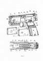
Фиг. 1. Общий вид слева ДЭШО и стреляющих картриджей (с автоматической расфиксацией от корпуса при выстреле и упрощенной конструкции).FIG. 1. General view on the left of the DESHO and firing cartridges (with automatic release from the body when fired and a simplified design).
Фиг. 2. Общий вид справа ДЭШО и стреляющих картриджей (с автоматической расфиксацией от корпуса при выстреле и упрощенной конструкции).FIG. 2. General view on the right of the DESHO and firing cartridges (with automatic release from the body when fired and a simplified design).
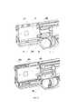
Фиг. 3. Вид ДЭШО со снятой половиной корпуса и вид разреза ДЭШО сверху.FIG. 3. View of DESHO with half of the body removed and section view of DESHO from above.
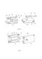
Фиг. 4. Разрез ДЭШО в двух разных плоскостях.FIG. 4. DESHO section in two different planes.
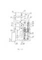
Фиг. 5. ДЭШО со снятыми половиной корпуса, нажимной частью замков принудительной фиксации картриджей и приводом-толкателем.FIG. 5. DESHO with half of the case removed, the press part of the locks for forced fixation of the cartridges and the drive-pusher.
Фиг. 6. Устройство стреляющего картриджа с автоматической расфиксацией.FIG. 6. The device of the firing cartridge with automatic release.
Фиг. 7. Устройство стреляющего картриджа упрощенной конструкции.FIG. 7. The device of the shooting cartridge of a simplified design.
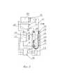
Фиг. 8. Блок-схема высоковольтного коммутатора ДЭШО с 2-мя стреляющими картриджами.FIG. 8. Block diagram of a high-voltage switchboard DESHO with 2 firing cartridges.
Фиг. 9. Блок-схема высоковольтного коммутатора ДЭШО с 3-мя стреляющими картриджами.FIG. 9. Block diagram of a high-voltage switchboard DESHO with 3 firing cartridges.
Фиг. 10. ДЭШО с высоковольтным коммутатором соленоидного привода и поворотным приводом фиксаторов стреляющих картриджей, общий вид и вид со снятой половиной корпуса.FIG. 10. DESHO with a high-voltage switch of the solenoid drive and a rotary drive of the firing cartridge clamps, general view and view with half of the body removed.
Фиг. 11. ДЭШО с коммутатором соленоидного привода разрезы сверху на разную глубину.FIG. 11. DESHO with a solenoid drive commutator cuts from above to different depths.
Фиг. 12. Блок схема высоковольтного коммутатора с соленоидным приводом.FIG. 12. Block diagram of a high-voltage switch with a solenoid drive.
Фиг. 13. Опытное ДЭШО со снятой половиной корпуса.FIG. 13. Experienced DESHO with half of the body removed.
Фиг. 14. Высоковольтные коммутаторы соленоидного привода и с приводом электродвигателем вид сверху.FIG. 14. High voltage switches of solenoid drive and electric motor drive top view.
Фиг. 15. Высоковольтные коммутаторы соленоидного привода и с приводом электродвигателем вид сбоку.FIG. 15. High voltage switches of solenoid drive and electric motor drive side view.
Осуществление изобретения.Implementation of the invention.
Фиг. 1 и Фиг. 2. ДЭШО состоит из корпуса 1 собранного из двух симметричных половин, в кармане (полости) корпуса расположены фиксируемые в корпусе 1 при заряжании стреляющие картриджи 2. Снаружи корпуса с обеих сторон расположены движки 3 экстракции картриджей из корпуса 1 при разряжании оружия для хранения или перезаряжания новыми картриджами взамен отстрелянных. На Фиг. 1 ДЭШО заряжен картриджами 2 с автоматической расфиксацией от корпуса при выстреле. Внизу для примера расположен как картридж с автоматической расфиксацией, так и картридж упрощенной конструкции (картридж пониженной стоимости, см. ниже).FIG. 1 and FIG. 2. DESHO consists of a
Стреляющий картридж 2 (далее по тексту - тип 2) с автоматической пиротехнической расфиксацией от корпуса при выстреле принципиально не отличаются от стреляющих картриджей по патенту [5] но имеют газовый двигатель, который в отличие от картриджей по патенту [5] при выстреле не выдвигает из картриджа выступ, а вдвигает имеющийся на картридже 2 подвижный выступ 4 внутрь корпуса картриджа заподлицо с образующей поверхность корпуса картриджа. На корпусе картриджа 2 выполнены выемки 5 фиксации картриджа в корпусе 1 деталью спускового механизма и выемки 7 принудительной фиксации в корпусе 1. Стреляющий картридж 8 (далее по тексту - тип 8) пониженной стоимости (упрощенной конструкции) не имеет газового двигателя, но также имеет выступ 9 выполненный заодно с корпусом картриджа.Shooting cartridge 2 (hereinafter referred to as type 2) with automatic pyrotechnic release from the body during firing does not fundamentally differ from the shooting cartridges according to the patent [5], but they have a gas engine, which, unlike cartridges according to the patent [5], does not push out of the protrusion of the cartridge, and pushes the
Стреляющий картридж 2 с автоматической пиротехнической расфиксацией от корпуса при выстреле принципиально не отличаются от стреляющих картриджей по патенту [5] но имеют газовый двигатель, который в отличие от картриджей по патенту [5] при выстреле не выдвигает из картриджа выступ как по патенту [5], а вдвигает имеющийся на картридже 2 подвижный выступ 4 внутрь корпуса картриджа заподлицо с образующей корпус картриджа. Внутреннее устройство картриджей описано по Фиг. 6 и Фиг. 7. Спусковой крючок 6 предназначен для запуска электронной схемы ДЭШО вырабатывающей поражающие высоковольтные импульсы электротока, инициирования выстрелов стреляющих картриджей 2 или 8, фиксации их в корпусе 1 при выстреле и времени, в течение которого цель поражается электротоком, а также для расфиксации картриджей от корпуса 1 после выстрела. С каждой стороны корпуса расположены нажимные части 10 замков принудительной фиксации картриджей в корпусе 1. На переднем торце корпуса 1 расположен общий боевой электрод 11 и боевые электроды 12 и 13. Между электродом 11 и электродом 12 и между электродом 11 и электродом 13 расположены так называемые "боевые (или "рабочие") искровые промежутки" в которых развивается "боевой (или "рабочий") искровой электроразряд" вырабатываемый высоковольтным узлом ДЭШО как в случае контактного применения ДЭШО, так и в случае дистанционного выстрела стреляющим картриджем.The firing
В рукоятке ДЭШО расположен источник электропитания в виде электрической батареи (или аккумулятора) 14 съемного или постоянного типа, в торце корпуса 1 расположен предохранитель 15 и кнопки (выключатели) 16 управления режимами работы ДЭШО, а также может располагаться дисплей-индикатор 17 работы электронных систем оружия. Для реализации указанных ниже вариантов работы заявляемого ДЭШО кнопок 16 может быть и больше 2-х (показанных на фигуре), однако различные необходимые режимы работы могут быть реализованы программированием при помощи различного количества и длительности нажатия только на две кнопки как это принято при программировании широко распространенных на сегодня различных электронных устройств с сенсорным или кнопочным программированием при небольшом количестве кнопок или мест сенсорного воздействия на программируемую электронную схему.In the handle of the DESHO there is a power source in the form of an electric battery (or accumulator) 14 of a removable or permanent type, a
Фиг. 3. Стреляющий картридж тип 2 или тип 8 фиксируется в корпусе 1 за выступ 4 или 9 на корпусе картриджа подвижным подпружиненным фиксатором 18 (размещенным в каждой половине корпуса 1) перемещающимся вертикально вниз относительно корпуса оружия при взаимодействии с подпружиненным приводом-толкателем 19 (размещенным также в каждой половине корпуса 1) и соединенным с движком 3. При нажатии пальцем руки пользователя движка 3 и соответственном перемещении привода-толкателя 19 вперед относительно корпуса оружия он взаимодействует с фиксатором 18 перемещая его вниз относительно корпуса оружия и при этом происходит расфиксация выступа 4 или 9 картриджа от фиксатора 18 и картридж выталкивается (экстрактируется) из корпуса оружия одним из двух расположенных в корпусе 1 подпружиненных выбрасывателей (экстракторов) выталкивающие пружины которых сжимаются корпусами картриджей при заряжании картриджей в карман размещения картриджей оружия. Таким образом при нажатии на движки 3 большим или указательным пальцем руки удерживающей оружие можно производить принудительное разряжание оружия от заряженных в него картриджей в случае необходимости разряжания оружия (например для хранения) и быструю принудительную экстракцию стреляного картриджа после выстрела. На Фиг. 3 изображен тип 2 стреляющего картриджа, но экстракция типа 8 стреляющего картриджа осуществляется таким же образом.FIG. 3. A
В корпусе 1 расположена электронная схема вырабатывающая высоковольтное поражающее цель напряжение электротока и включающая в себя как свою часть управляющий блок с микроконтроллером управления узлами схемы, в том числе и высоковольтным коммутатором (см. ниже), инвертер 20 (в общем корпусе которого может находиться и управляющий блок включающий в себя микроконтроллер), высоковольтный узел 21 (включающий в себя набор конденсаторов, газовых разрядников, диода, высоковольтного импульсного трансформатора), электронную схему очередности инициирования стреляющих картриджей, таймер управления временем вырабатывания поражающего цель напряжения, при необходимости дисплей-индикатор 17 работы электронной схемы, аккумулятора (и иной информации о работе оружия) и аккумулятор 14 питания ДЭШО.In
Фиксатор 18 может иметь привод как от движка 3 (кнопки) с продольным движением относительно длины оружия так и от движка с поперечным движением или с поворотным движением движка вокруг некоторой оси. Продольное, поперечное или поворотное движение движка относительно корпуса оружия определяется конструктором. Поворотное движение, как и поперечное движение движка может передаваться к фиксатору 18 общеприменительными и понятными любому техническому специалисту простыми устройствами в виде рычагов, наклонных плоскостей, шестеренно-реечных передач либо их комбинациями (например, см. Фиг. 10). В корпусе 1 расположен также электромеханический высоковольтный коммутатор 22 (пронумеровано его основание) имеющий в своем составе электропривод с вращением 23 (электродвигатель без передачи или с шестеренчатой передачей, например сервомашинка (стандартная аналоговая или цифровая рулевая машинка авиамоделей микро или нано класса), нетокопроводные трубчатые направляющие 24, неодимовый магнит 25 и стальную спиральную пружину 26 растяжения. На нижнем виде Фиг. 3 изображен разрез ДЭШО сверху где видны нетокопроводные трубчатые направляющие 24, неодимовый магнит 25, спиральная пружина 26 растяжения, вал 27 электропривода 23, подвижный контакты 28 и 29 (представляющие собой законцовки спиральной пружины 26 растяжения), отрезки 30 и 31 высоковольтного кабеля соединяющие неподвижные контакты 32 и 33 с электродами 12 и 13, щеточный контакт 34 первого вывода 35 высоковольтного узла 21, нетокопроводные трубчатый корпус 36 защитного искрового разрядника, разрядные электроды 37 защитного искрового разрядника, второй вывод 38 высоковольтного узла 21.The
Фиг. 4. При нажатии на спусковой крючок 6 для производства выстрела он своим передним выступом воздействует на деталь 39 спускового механизма, которая своим передним зубцом входит в выемку 5 фиксации картриджа. При конечном ходе спускового крючка 6 он своим задним выступом включает тактовую кнопку 40 которая и запускает электронную схему, вырабатывающую высоковольтное поражающее цель напряжение электротока и низковольтное напряжение электротока, инициирующее метательный заряд пиротехнического вещества картриджа, который производит метание в цель токопроводов, а также запускает в действие высоковольтный коммутатор 22 в режим работы, установленный заранее при помощи кнопок 16. В момент выстрела газовый двигатель картриджа перемещает деталь 41 картриджа имеющую с обратной стороны выступ 4 внутрь картриджа так, что выступ 4 выходит из зацепления с подпружиненным фиксатором 18 и удерживается от экстрактирования из корпуса оружия подпружиненным экстрактором 42 только зубцом детали 39 вошедшим в выемку 5 фиксации картриджа. После поражения цели пользователь отпускает спусковой крючок 6, зубец детали 39 выходит из выемки 5, и происходит расфиксация стреляного картриджа от корпуса 1 с экстрактированием картриджа с выброшенными в цель токопроводами из корпуса 1 экстрактором 42 под действием его сжатой при заряжании оружия картриджем пружины 43. На фигуре показаны также контакты 44 низковольтного инициирования пиротехнического заряда картриджа.FIG. 4. When the
Фиг. 5. На фигуре для лучшей обзорности со сборки ДЭШО снята нажимная часть 10 и привод-толкатель 19. При необходимости производства иммобилизации двух правонарушителей или производства двух быстроследующих друг за другом выстрелов (дублированного выстрела) для увеличения надежности поражения или ареста одного вооруженного правонарушителя с учетом вероятности возможного отказа иммобилизации из-за вероятности обрыва токопровода или незакрепления токопровода на цели при первом выстреле правоохранитель-пользователь ДЭШО перед началом стрельбы нажимает на нажимные части 10 замков принудительной фиксации картриджей в корпусе 1 указательным пальцем руки удерживающей оружие перемещая их вверх относительно корпуса оружия. Ригели 45 замков 46 (соединенных с нажимной частью 10) входят в выемки 7 картриджа для принудительной фиксации в корпусе 1. В этом случае даже при расфиксированном с фиксатором 18 выступом 4 (как изображено на Фиг. 5) (фиксатор 18 опущен, а выступ 4 картриджа вдвинут газовым двигателем после выстрела) и отпущенном спусковом крючке 6 картридж 2 остается в оружии, то есть автоматической экстракции стреляного картриджа не происходит.FIG. 5. In the figure, for better visibility, the
Это позволяет в случае поднимания пользователем двух нажимных частей 10 перед стрельбой иммобилизировать две цели одновременно токопроводами двух картриджей (режим ареста) или одну вооруженную цель токопроводами двух картриджей для надежности ее поражения дублированным выстрелом.This allows, if the user lifts two
Фиг. 6. Силовой корпус 47 картриджа тип 2, передняя заглушка 48, деталь 41 с выступом 4, поршень с вилкой 49 газового двигателя, газовые каналы 50, заглушка каналов 51, пиротехнический заряд 52 с электроинициированием, метаемые зонды 53 с токопроводом, окно 54 движения детали 41 с выступом 4. При подаче напряжения электрического тока на пиротехнический заряд 52 он инициируется, и газы, образующиеся газы сгорания заряда, проходят по каналам 50 в ствольные каналы картриджа, производя метание зондов 53 с токопроводом в цель. Одновременно газы сгорания заряда воздействуют на поршень с вилкой 49 имеющей скосы, которые, взаимодействуя с ответными скосами детали 41, опускают ее в окне 54 так, что выступ 4 детали 41 выступающий над образующей поверхностью корпуса 47 до выстрела опускается в положение заподлицо с образующей поверхность корпуса 47. При этом происходит расфиксация картриджа от фиксатора 18 и соответственно от корпуса 1 оружия.FIG. 6.
Фиг. 7. Силовой корпус 55 картриджа типа 8, газовые каналы 56, разрезные заглушки 57 ствольных каналов (аналогичные типа картриджа 2), пиротехнический заряд 52 с электроинициированием, метаемые зонды 53 с укладкой токопровода внутри (на разрезе зондов укладка не показана), выступ 9. При подаче напряжения электрического тока на пиротехнический заряд 52 он инициируется и газы образующиеся газы сгорания заряда проходят по каналам 56 в ствольные каналы картриджа, производя метание зондов 53 с токопроводом в цель.FIG. 7.
Фиг. 8. Подвижные контакты 28 и 29 высоковольтного коммутатора двигающиеся в нетокопроводных трубчатых направляющих 24 прикреплены к концам стальной спиральной пружины 26 растяжения (которая может иметь покрытие из меди или серебра) огибающей кольцевой или дисковый неодимовый магнит 25 с никелевым покрытием к которому магнитными силами притягивается изгибающаяся часть пружины 26. Магнит 25 может вращаться от электропривода 23 управляемого от блока 58 электронной схемы ДЭШО. Управляющий блок 58 может составлять часть инвертера 20. К магниту 25 примыкает щеточный контакт 34, причем его щетка может как примыкать к магниту для непосредственного гальванического контакта, так и отстоять от него с небольшим (доли миллиметра) зазором. Щеточный контакт 34 соединен высоковольтным кабелем с первым выводом 35 высоковольтного узла 21 вырабатывающего импульсное или переменное напряжение в 40-80 кВ, а второй вывод 38 высоковольтного узла 21 соединен с общим боевым электродом 11 ДЭШО являющимся и общим электродом стреляющих картриджей. Электрически параллельно высоковольтным выводам 35 и 38 генератора узла 21 подключен защитный искровой разрядник с разрядными электродами 37. Высоковольтный коммутатор работает следующим образом:FIG. 8. Moving
При работе ДЭШО (при контактном или дистанционном действии) высоковольтный узел 21 питаемый от управляющего блока 58 в свою очередь питаемого от электрической батареи или аккумулятора 14 и содержащего в своем составе инвертер 20 вырабатывает высоковольтное поражающее напряжение электрического тока, которое через его первый вывод 35 поступает на щеточный контакт 34, а через второй вывод 38 на общий боевой электрод 11. Гибкая пружина 26 притягиваемая к магниту 25 приводимому в знакопеременное вращение электроприводом 23 управляемым блоком 58 по алгоритму вращения с определенной частотой смены знаков вращения, перемещается согласовано с вращением магнита 25 и соединяет подвижные контакты 28 и 29 попеременно с неподвижными контактами 32 и 33, в такой последовательности, что в зависимости от положения внутри трубчатых направляющих 24 подвижных контактов и их контактирования с неподвижными контактами (непосредственный контакт или с зазором в доли миллиметра) высоковольтное напряжение электротока поступает то на электрод 12 и далее через боевой искровой промежуток на общий электрод 11, то на электрод 13 и далее через боевой искровой промежуток на общий электрод 11.During the operation of the DESHO (with contact or remote action), the high-
На Фиг. 8 замкнуты неподвижный контакт 32 и подвижный контакт 29 для образования высоковольтного искрового разряда в рабочем искровом промежутке между электродами 12 и 11. При этом если токопроводы стреляющего картриджа 59 в этот момент выстрелены и закрепились на цели, то по ним на цель подается высоковольтное поражающее напряжение электротока. На Фиг. 8; Фиг. 9; Фиг. 10 направление выстреливания токопроводов из стреляющих картриджей указаны стрелкой. При повороте магнита 25 в обратную сторону контакты 32 и 29 разомкнуться, а контакты 33 и 28 замкнуться. Искровой разряд образуется в промежутке между боевыми электродами 13 и 11 и соответственно подается на токопроводы картриджа 60 (и при попадании их в цель на саму цель). При знакопеременном вращении магнита 25 высоковольтное поражающее напряжение электротока будет подаваться попеременно на электроды 11; 12 и 11; 13. При выстреливании токопроводов обоих картриджей в две цели высоковольтное поражающее напряжение электротока будет подаваться попеременно на обе пораженные токопроводами цели.FIG. 8 closed fixed
При работе высоковольтного коммутатора ДЭШО может работать по нескольким алгоритмам исполнения.When a high-voltage switch is in operation, DESHO can operate according to several execution algorithms.
Простейший алгоритм работы в случае выстрелов из ДЭШО по двум целям предусматривает работу высоковольтного узла 21 который непрерывно (с оговоркой на максимальное допустимое время подачи электрического тока на биоцель по установленным правовым и медицинским нормам) вырабатывает высоковольтное поражающее напряжение электрического тока, а коммутатор с некоторой частотой переключения попеременно соединяет и разъединяет подвижные и неподвижные контакты в трубчатых направляющих производя попеременную подачу высоковольтного поражающего напряжения электротока на две цели с закрепленными на них токопроводами выстрелянными из картриджей. В таком исполнении коммутатора в момент положения магнита 25 и соответственно пружины 26, в которых оба подвижных и неподвижных контакта рассоединены (срединное (промежуточное) положение подвижных контактов в трубчатых направляющих) на высоковольтном импульсном трансформаторе высоковольтного узла 21 возникает перенапряжение, которое может привести к внутреннему высоковольтному пробою трансформатора. Поэтому трансформатор узла 21 защищен защитным искровым разрядником, в искровом разрядном промежутке которого между разрядными электродами 37 в момент полного рассоединения обоих подвижных и неподвижных контактов (срединное положение обоих подвижных контактов в трубчатых направляющих 24) происходит паразитный высоковольтный искровой разряд. Расстояние между разрядными электродами 37 в защитном разряднике и соответственно напряжение зажигания должно быть несколько больше чем эти показатели для электродов 11; 12 и 11; 13. Простейший алгоритм использует и простейшее исполнение электропривода коммутатора, использующего коллекторный или шаговый двигатель постоянного тока без использования датчиков положения подвижных контактов 28 и 29.The simplest algorithm of operation in the case of shots from the DESHO for two purposes provides for the operation of a high-
Более сложный энергосберегающий алгоритм предусматривает использование датчиков положения подвижных контактов 28 и 29 или датчиков угла поворота магнита 25, или датчика угла поворота вала электропривода 23. В этом случае один датчик (или два датчика) положения подвижных контактов соединенных с управляющим блоком 58 при работе коммутатора выключает узел 21 при каждом положении подвижных контактов 28 и 29 в котором может происходить высоковольтный пробой в узле 21 (описанное выше срединное (для простоты понимания) или приближающееся к нему положение (зависящее от запаса высоковольтного импульсного трансформатора по пробивному расстоянию по воздуху сверх конструктивно установленного расстояния между боевыми электродами). Таким образом паразитный искровой разряд в защитном искровом разряднике не развивается, что позволяет уменьшить энергопотребление от источника электропитания 14.A more complex energy-saving algorithm involves the use of position sensors of the
Другой алгоритм работы коммутатора также с использованием датчиков положения подвижных контактов предусматривает установку в замкнутое положение только одной пары подвижных и неподвижных контактов в зависимости от того какой именно стреляющий картридж выстрелил токопроводы в цель. В этом случае через выстреленные токопроводы первого выстреленного картриджа, на первую цель будет подаваться полная непрерывная мощность поражающего напряжения электротока от узла 21. При выстреливании токопроводов второго стреляющего картриджа во вторую цель коммутатор подаст полную непрерывную мощность поражающего напряжения электротока на вторую цель, отключив подачу мощности на первую цель. Алгоритмы работы устанавливаются пользователем при помощи кнопок 16 программирующего управляющий блок 58, который организует работу коммутатора и вырабатывание поражающего напряжения электротока.Another algorithm for the operation of the switch, also with the use of moving contact position sensors, provides for the installation in the closed position of only one pair of movable and fixed contacts, depending on which firing cartridge fired the conductors at the target. In this case, through the fired conductors of the first fired cartridge, the first target will be supplied with the full continuous power of the destructive voltage of the electric current from the
При использовании в качестве электропривода коллекторного или бесколлекторного электродвигателя без редуктора обеспечивающего наибольшую возможную скорость переключения подвижных контактов (до десятков герц) целесообразно применение датчиков положения подвижных контактов не только для исключения паразитного искрового разряда на защитном искровом разряднике, но также для отключения электродвигателя электропривода при приходе подвижных контактов в крайние положения и включения электродвигателя с плавным нарастанием тока для предотвращения износа щеток электродвигателя из-за больших пусковых токов и токов самоиндукции при резкой остановке электродвигателя. При использовании в качестве электропривода рулевой машинки угловое положение выходного вала, на котором устанавливается магнит 25 (а значит и положение подвижных контактов) всегда известно без дополнительных датчиков поскольку датчик углового положения всегда встроены в саму рулевую машинку.When using as an electric drive a collector or brushless electric motor without a gearbox providing the highest possible switching speed of movable contacts (up to tens of hertz), it is advisable to use position sensors of movable contacts not only to exclude a parasitic spark discharge on a protective spark gap, but also to turn off the electric motor of the electric drive when moving contacts to extreme positions and turning on the electric motor with a smooth increase in current to prevent wear of the electric motor brushes due to high starting currents and self-induction currents when the electric motor stops abruptly. When using a steering gear as an electric drive, the angular position of the output shaft on which the
Фиг. 9. Высоковольтный коммутатор может коммутировать подачу высоковольтного поражающего напряжения электрического тока также и на три поражаемые цели (т.е. на три стреляющих картриджа) как и трехзарядный ДЭШО Taser Х3.FIG. 9. The high-voltage switch can switch the supply of high-voltage destructive voltage of electric current to three targets (ie, three firing cartridges) as well as the three-charge DESHO Taser X3.
Исполнение коммутатора на три стреляющих картриджа без датчиков положения подвижных контактов отличается от исполнения коммутатора по Фиг. 8 тем, что искровой разрядный промежуток защитного разрядника (Фиг. 8) перенесен в рабочий искровой разрядный промежуток 61 третьего стреляющего картриджа 62 между контактными электродами 63 и 64 при этом вывод 35 высоковольтного узла 21 соединен с электродом 64, а вывод 38 высоковольтного узла 21 соединен с электродом 63. Как сказано в описании по Фиг. 8 при работе коммутатора, в срединном положении подвижных контактов 28 и 29 в трубчатых направляющих искровой разряд происходит в искровом разрядном промежутке защитного разрядника. В случае перенесения функции защитного разрядника на искровой промежуток 61 третьего стреляющего картриджа 62 в срединном положении подвижных контактов в трубчатых направляющих искровой разряд образуется в разрядном промежутке 61, и при выстреливании токопроводов третьего стреляющего картриджа 62 в цель поражающее напряжения электрического тока поступает в третью поражаемую цель при срединном положении подвижных контактов. Расстояние между разрядными электродами 63 и 64 в разрядном промежутке 61 и соответственно напряжение зажигания искрового разряда должно быть несколько больше чем эти характеристики для разрядных промежутков 65 и 66 картриджей 67 и 68. Заявляемое устройство в приведенных выше исполнениях на два или три стреляющих картриджа имеет не два или три источника высоковольтного поражающего напряжения электрического тока (высоковольтных узлов) как ДЭШО-прототип, а только один, что уменьшает стоимость ДЭШО и в связи с отсутствием в конструкции импортных и дорогостоящих компонентов нескольких высоковольтных узлов. При этом габаритные размеры заявляемого устройства позволяют размещать его в ДЭШО в виде пистолета с габаритами сходными с огнестрельным оружием, носимым в кобуре, и производить ДЭШО с коммутацией высоковольтного разряда для силовых служб России. Расстояние между разрядными электродами 37 в защитном разряднике и соответственно напряжение зажигания должно быть несколько больше чем эти характеристики для электродов 12; 11 и 13; 11.The design of the switch for three firing cartridges without moving contact position sensors differs from the design of the switch according to FIG. 8 by the fact that the spark discharge gap of the protective spark gap (Fig. 8) is transferred to the working
Фиг. 10. На верхнем виде фигуры корпус 69 ДЭШО, стреляющие картриджи тип 2 или тип 8 (на фиг. изображены картриджи тип 8), нажимно-поворотный рычаг 70, спусковой крючок 6, выключатель 71 высоковольтного коммутатора, аккумулятор 14 питания. Устройство и вид боевых электродов ДЭШО не отличаются от приведенных на Фиг. 1. Назначение и действие выключателя 71 высоковольтного коммутатора описано ниже в разделе "Варианты режимов работы ДЭШО".FIG. 10. In the upper view of the figure, the
На нижнем виде фигуры выключатель 71 (описание работы см. ниже) высоковольтного коммутатора снят с корпуса для лучшей обзорности других деталей. Картриджи фиксируются в корпусе 69 за выступ 9 на корпусе картриджа подвижным подпружиненным фиксатором 18 (размещенным в каждой половине корпуса) перемещающимся вертикально вниз относительно корпуса оружия при взаимодействии с подпружиненным приводом-толкателем 72 (размещенным также в каждой половине корпуса) и взаимодействующим с водилом 73 с осью проходящей сквозь стенку половины корпуса и соединенной с нажимно-поворотным рычагом 70. При нажатии пальцем руки пользователя на рычаг 70 и повороте соединенным с ним водила 73 и соответственном перемещении взаимодействующего с водилом привода-толкателя 72 вперед относительно корпуса оружия он взаимодействует с фиксатором 18 перемещая его вниз относительно корпуса оружия и при этом происходит расфиксация выступа 9 картриджа от фиксатора 18 и картридж выталкивается (экстрактируется) из корпуса оружия одним из двух расположенных в корпусе подпружиненных выбрасывателей (экстракторов) выталкивающие пружины которых сжимаются корпусами картриджей при заряжании картриджей в карман размещения картриджей оружия. Таким образом при нажатии на рычаг 70 пальцем руки удерживающей оружие можно производить как разряжание оружия от заряженных в него картриджей в случае необходимости разряжания оружия (например для хранения) так и быструю принудительную экстракцию стреляного картриджа после выстрела.In the lower view of the figure, the switch 71 (see below for operation) of the high-voltage switch has been removed from the case for better visibility of other parts. The cartridges are fixed in the
В корпусе 69 расположена электронная схема, вырабатывающая высоковольтное поражающее цель напряжение электротока и включающая в себя как свою часть микроконтроллер управления узлами схемы, инвертер 20, высоковольтный узел 21, электронную схему очередности инициирования стреляющих картриджей, таймер управления временем вырабатывания поражающего цель напряжения, при необходимости дисплей-индикатор 17 работы электронной схемы, аккумулятора (и иной информации о работе оружия) и аккумулятор 14 питания ДЭШО. В корпусе 69 расположен также электромеханический высоковольтный коммутатор 74 (нумеровано его основание) имеющий соленоиды 75, нетокопроводные трубчатые направляющие 76, защитный разрядник 77.In
На Фиг. 11 изображены разрезы ДЭШО с высоковольтным коммутатором соленоидного привода сверху на разную глубину, где видно устройство коммутатора. Соленоиды 75 (обмотки не показаны), стеклянные или пластиковые трубчатые направляющие 76, защитный разрядник 77, пружины 78 соединенные между собой электрически, а также соединены электрически с выводом 35 высоковольтного узла 21. В каждой из трубчатых направляющих 76 может перемещаться магнитная контактная система состоящая из оболочки в которой расположены два неодимовых магнита 79 обращенные друг к другу одноименными полюсами, немагнитный разделитель 80 магнитов и токопроводный соединитель 81 магнитов. В направляющих 76 расположены неподвижные контакты 82 и 83 соединенные отрезками высоковольтного кабеля с боевыми электродами 13 и 12.FIG. 11 shows the sections of the DESHO with the high-voltage switch of the solenoid drive from above to different depths, where the switch device is visible. Solenoids 75 (windings not shown), glass or plastic tubular guides 76,
Описанные магнитные контактные системы представляют собой фактически подвижные контакты коммутатора, приводимые в движение с длинным ходом (длинный ход в соленоиде это свойство связанных магнитных систем описанной конструкции) посредством воздействия на магнитные контактные системы электромагнитного поля соленоидов, на которые последовательно подаются импульсы электротока необходимой длительности и частоты от управляющего блока 58 для перемещения магнитных контактных систем внутри направляющих 76 с частотой задаваемой конструктором ДЭШО по различным требованиям. Соленоидный высоковольтный коммутатор в отличие от высоковольтного комутатора с приводом от электродвигателя описанного выше может обеспечивать скорость переключения (коммутации) высокого напряжения с частотой до сотни герц и более (зависящей от выбранной длины максимального хода магнитной системы, ее массы и подводимой к соленоидам мощности электротока а также от выбранного конструктивно расстоянием искрового электропробоя по воздуху высоковольтного узла 21). Второй вывод 38 высоковольтного узла 21 соединен с общим боевым электродом 11 ДЭШО являющимся и общим электродом стреляющих картриджей. Электрически параллельно высоковольтным выводам 35 и 38 генератора узла 21 подключен защитный искровой разрядник 77. Принцип коммутации высоковольтного коммутатора соленоидного привода не отличается от описанного по Фиг. 8, за исключением той разницы, что вместо электромеханического привода подвижных контактов в виде электродвигателя используется соленоидный привод. Высоковольтный коммутатор соленоидного привода может коммутировать подачу высоковольтного поражающего напряжения электрического тока и на три поражаемые цели (на три стреляющих картриджа) как и трехзарядный ДЭШО Taser Х3 (США), принцип коммутации не отличается от описанного по Фиг. 9, т.е. рабочий искровой разрядный промежуток третьего стреляющего картриджа является искровым разрядным промежутком защитного разрядника.The described magnetic contact systems are actually movable contacts of the switch, driven with a long stroke (long stroke in a solenoid is a property of coupled magnetic systems of the described design) by acting on the magnetic contact systems of the electromagnetic field of solenoids, which are sequentially supplied with electric current pulses of the required duration and frequency from the
Фиг. 12. Соленоиды 75, трубчатые направляющие 76, защитный разрядник 77, пружины 78 соединенные между собой электрически, а также соединены электрически с выводом 35 высоковольтного узла 21. В каждой из трубчатых направляющих 76 при подаче тока на соленоиды от управляющего блока 58 перемещается магнитная контактная система, состоящая из немагнитной оболочки, в которой установлены неодимовые магниты 79, обращенные друг к другу одноименными полюсами, немагнитный разделитель 80 магнитов и токопроводный соединитель 81 магнитов (показан штриховой линией). В направляющих 76 расположены неподвижные контакты 82 и 83 соединенные отрезками высоковольтного кабеля с боевыми электродами 13 и 12. Высоковольтный коммутатор работает следующим образом:FIG. 12.
При работе ДЭШО (при контактном или дистанционном действии) высоковольтный узел 21 питаемый от управляющего блока 58 в свою очередь питаемого от электрической батареи или аккумулятора 14 и содержащего в своем составе инвертер 20 вырабатывает высоковольтное поражающее напряжение электрического тока, которое через его первый вывод 35 поступает на соединенные между собой электрически проводящие пружины 78 и далее через соединитель 81 полюса магнитов обращенных - к неподвижным контактам 82 и 83, на которых могут быть установлены еще и токопроводные острые законцовки (как видно на Фиг. 11). На соленоиды попеременно поступают однополярные импульсы электротока по алгоритму подачи и выключения тока с определенной частотой вырабатываемые управляющим блоком 58 при этом каждая из двух магнитных контактных систем попеременно совершает длинные ходы сжимая пружины 78 которые разжимаясь при отключении тока в соленоиде возвращают магнитные контактные системы в начальное положение (замкнутое с неподвижными контактами) в направляющих 76, разрывая и замыкая электрическую цепь высоковольтного напряжение электротока, подаваемого то на электрод 12, то на электрод 13.During the operation of the DESHO (with contact or remote action), the high-
На Фиг. 12 электроток подан блоком 58 на левый по фигуре соленоид. Левая магнитная контактная система втянута в соленоид сжав левую пружину 78 и соответственно замкнуты неподвижный контакт 83 и правая контактная магнитная система для образования высоковольтного искрового разряда, вырабатываемого узлом 21 в боевом искровом промежутке между электродами 11 и 12. При этом если токопроводы стреляющего картриджа 84 в этот момент выстрелены и закрепились на цели, то по ним на цель подается высоковольтное поражающее напряжение электротока (направление выстреливания токопроводов из стреляющих картриджей указано стрелкой). При отключении блоком 58 электротока от левого соленоида и подаче электротока на правый соленоид правая магнитная контактная система втянется в правый соленоид и контакт 83 разомкнется от правой магнитной контактной системы, а левая магнитная контактная система под действием сжатой пружины 78 вернется в начальное положение и замкнет контакт 82 для образования высоковольтного искрового разряда в боевом искровом промежутке между электродами И и 13 на картридже 85. При последовательной подаче электротока на правый и левый соленоиды высоковольтное поражающее напряжение электротока от узла 21 будет подаваться попеременно на электроды 11; 12 и 11; 13. При выстреливании в две цели токопроводов обоих картриджей высоковольтное поражающее напряжение электротока будет подаваться попеременно на обе пораженные токопроводами цели.FIG. 12, electric current is supplied by
Схемотехника высоковольтного коммутатора соленоидного привода позволяет точно знать положение подвижных магнитных контактных систем без специальных датчиков их положения, так как разомкнутое положение неподвижных контактов коммутатора и магнитных контактных систем обеспечивается только в момент подачи тока на соленоид и соответственно в этот же момент управляющий блок 58 может прервать подачу высоковольтного поражающего напряжения электрического тока на магнитную контактную систему и неподвижный контакт. Таким образом работа узла 21 не будет осуществляться в срединном положении неподвижных контактов и подвижных магнитных контактных систем, а значит, что разрядник 77 в коммутаторе соленоидного привода может либо не применяться, либо оставаться только как предохранительный на случай отказа в управлении в блоке 58. Таким образом в коммутаторе соленоидного привода даже без использования датчиков положения можно осуществить удержание двух целей одновременно в иммобилизованном состоянии без паразитного расходования энергии источника электропитания ДЭШО на образование искрового разряда в искровом разряднике при срединном положении магнитных контактных систем в процессе коммутации. Кроме того коммутатор соленоидного привода имеет меньшую инерционность по сравнению с коммутатором с приводом электродвигателем и соответственно большую возможную частоту переключения и его применение в ДЭШО предпочтительнее.The circuitry of the high-voltage switch of the solenoid drive allows you to accurately know the position of the moving magnetic contact systems without special sensors of their position, since the open position of the fixed contacts of the switch and magnetic contact systems is provided only at the moment of supplying current to the solenoid and, accordingly, at the same moment, the
Варианты режимов работы ДЭШО.Variants of DESHO operating modes.
По предполагаемому изобретению достигаются весьма разнообразные варианты работы (использования) ДЭШО.According to the proposed invention, very diverse options for the operation (use) of the DESHO are achieved.
При необходимости демонстрации искрового электроразряда правонарушителю для снятия у него агрессии или для применения контактным способом (без выстрелов) пользователь при помощи одной из кнопок 16 отключает работу части электронной схемы, отвечающую за очередность инициирования стреляющих картриджей для выстрелов. В этом случае низковольтное напряжение электротока не вырабатывается и не подается на электроконтакты 44 (см. Фиг. 4) электроинициирования пиротехнического заряда картриджей. При отключении указанной части электронной схемы от работы при нажатии на спусковой крючок 6 электронная схема вырабатывает только поражающее напряжение электротока с образованием между электродами 11 и 12, 13 боевого искрового разряда при демонстрации электроразряда либо при контакте электродов 11 и 12, 13 с телом биоцели производит на цель иммобилизирующее воздействие. ДЭШО может иметь переключатель-селектор (например кнопку 16) работы части электронной схемы очередности инициирования стреляющих картриджей. Переключатель-селектор может переключать производство первого выстрела с правого картриджа на левый или наоборот. Такая функция применяется для удобства заряжания (дозаряжания) нового картриджа взамен стреляного в зависимости от праворукости или леворукости пользователя, так как удобнее дозаряжать оружие с одним отстреляным и экстрактированным картриджем той рукой которая находится ближе к стороне оружия с пустой полостью уже экстрактированного картриджа.If it is necessary to demonstrate a spark electric discharge to an offender to remove aggression from him or to use it by a contact method (without shots), the user, using one of the
Заряжание ДЭШО производится путем введения картриджей 2 в карман корпуса спереди, при этом сжимаются пружины 43 экстракторов 42 обеспечивающие экстракцию картриджей из карманов после выстрела или при разряжании ДЭШО. При введении картриджей в карман выступы 4 картриджей отжимают вниз относительно корпуса оружия подпружиненные фиксаторы 18, которые при полном введении картриджей в карманы защелкиваются на выступах 4 фиксируя картриджи в корпусе 1. Разряжание оружия производится нажатием на движки 3 и таким образом одно устройство ручной расфиксации картриджей от корпуса оружия выполняет как функцию устройства дублирующего автоматическую экстракцию, так и функцию устройства разряжания оружия.The loading of the DESHO is carried out by inserting the
При использовании ДЭШО дистанционного воздействия по умолчанию (без установок каких-либо дополнительных режимов работы кнопками 16) при нажатии на спусковой крючок поражающее напряжение электротока подается на инициируемый картридж и продолжается все время пока пользователь не отпустит спусковой крючок. При повторном нажатии на спусковой крючок поражающее напряжение электротока подается на второй инициируемый картридж и продолжается все время пока пользователь не отпустит спусковой крючок. При этом максимальное однократное и непрерывное время подачи поражающего напряжения электротока на цель как при контактном режиме использования описанном выше так и во всех нижеописанных режимах работы даже при условии неотпускании пользователем спускового крючка или в режимах ареста может прерываться программно в соответствие с законодательством и медико-биологическими нормами (для РФ непрерывное время 3 с), для США же время варьируется от 5 с до 30 с в зависимости от выходной мощности ДЭШО или рекомендаций экспертов). Максимальное время подачи поражающего напряжения электротока на цель варьируется также в зависимости от назначения ДЭШО (полицейское или гражданское). В полицейских моделях как в РФ, так и в США допускается увеличенное время воздействия на цель, или увеличенная выходная мощность поражающего электротока либо и то и другое вместе. При этом в связи с использованием в заявляемом ДЭШО единственного высоковольтного узла 21 допускается получение выходной мощности поражающего электротока максимальной для применяемого типа инвертера и энергоотдачи источника электропитания (электробатареи или аккумулятора), что принципиально недостижимо в ДЭШО-прототипе имеющего два высоковольтных узла.When using DESHO remote action by default (without setting any additional operating modes by buttons 16), when the trigger is pulled, a striking voltage of electric current is applied to the initiated cartridge and continues until the user releases the trigger. When the trigger is pressed again, the damaging voltage of the electric current is applied to the second initiated cartridge and continues until the user releases the trigger. At the same time, the maximum single and continuous time of supplying a damaging voltage of electric current to the target both in the contact mode of use described above and in all modes of operation described below, even if the user does not release the trigger or in arrest modes, can be interrupted programmatically in accordance with the legislation and medical and biological standards (for the Russian Federation, a continuous time of 3 s), for the USA, the time varies from 5 s to 30 s, depending on the output power of the DESHO or the recommendations of experts). The maximum time for applying a damaging electric current to a target also varies depending on the purpose of the DESHO (police or civilian). In police models, both in the Russian Federation and in the United States, an increased exposure time to a target, or an increased output power of a damaging electric current, or both together are allowed. At the same time, in connection with the use of a single high-
При необходимости ареста правонарушителя перед использованием ДЭШО пользователь должен нажать на нажимные части 10 замков 46 принудительной фиксации картриджей в корпусе 1 и при помощи одной из кнопок 16 включить режим работы оружия в режим работы таймера (режим ареста) продолжения работы поражающей части электронной схемы на определенное заданное время с прерыванием работы по окончанию задания или на прерывистый режим подачи (по установленному алгоритму подачи тока и паузы для восстановления сердечно-дыхательных функций биоцели) высоковольтного поражающего цель напряжения электротока на биоцель после отпускания спускового крючка. Кнопка перевода работы электронной схемы в режим ареста может быть связана с замком 46 или нажимной частью 10 замков механически или электрически (например, при помощи магнитного элемента закрепленного в замке 46 или части 10 и геркона расположенного в корпусе 1 и соединенного с кнопкой (или непосредственно с электронной частью оружия), включаясь при переводе нажимной части 10 в режим ареста. Такой режим работы ДЭШО позволяет поразить цель одним или двумя выстрелами положить оружие с работающей поражающей частью электронной схемы на землю и произвести арест правонарушителя с надеванием на него наручников. После производства ареста пользователь должен отключить режим работы оружия в режиме работы таймера продолжения работы поражающей части электронной схемы. Экстракция стреляных картриджей осуществляется нажатием указательным пальцем на нажимные части 10 замков перемещая их вниз относительно корпуса оружия.If it is necessary to arrest the offender before using the DESHO, the user must press the
При необходимости ареста одновременно двух правонарушителей (например, при предполагаемом конфликте с двумя правонарушителями) перед использованием ДЭШО пользователь должен нажать на нажимные части 10 замков 46 принудительной фиксации картриджей в корпусе 1 и при помощи одной из кнопок 16 перевести режим работы оружия в режим работы поражающей части электронной схемы и работы высоковольтного коммутатора. При этом при нажатии на спусковой крючок один раз коммутатор коммутирует поражающее напряжение электротока только на первый инициированный картридж причем поражается первая цель, при повторном нажатии на спусковой крючок инициируется второй картридж и поражается вторая цель, а коммутатор начинает коммутировать поражающее напряжение электротока на первый и второй картридж попеременно поддерживая иммобилизацию обеих целей. При необходимости произвести дублированный выстрел в вооруженного правонарушителя пользователь имеет возможность использовать режим ареста с двумя быстроследующими один за другим выстрелом в правонарушителя, но в этом случае полная выходная мощность при использовании коммутатора 22 без системы определения положения замкнутого и разомкнутого подвижного и неподвижного контакта (датчиков положения) не достигается, так как часть выходной мощности в единицу времени будет затрачиваться на образование паразитного искрового разряда в защитном разряднике (см. работа коммутатора 22). Поэтому режим дублированного выстрела целесообразно осуществлять либо при наличии выключателя 71 высоковольтного коммутатора (см. Фиг. 10) либо применением коммутатора только с соленоидным приводом с отключением его работы (например, кнопкой 16) в режиме использования для производства дублированного выстрела, так как в режиме остановки работы коммутатора (обесточивания) с соленоидным приводом оба подвижных контакта (магнитных систем) всегда находятся в замкнутом положении с неподвижными контактами (как на Фиг. 11).If it is necessary to arrest two offenders at the same time (for example, in case of an alleged conflict with two offenders), before using the DESHO, the user must press the
Выключатель (по существу замыкатель) 71 представляет собой перемещаемую по верхней поверхности корпуса ДЭШО в направляющих пластинчатую пластиковую деталь с боковыми выступами имеющую внутренний металлизированный электрический соединитель боковых выступов. При перемещении выключателя вперед боковые выступы соединяются с боевыми электродами 12 и 13, замыкая их между собой, и таким образом при любом положении подвижных контактов коммутатора с приводом от электродвигателя при его работе кроме срединного поражающее напряжение электротока от высоковольтного узла 21 поступает одновременно на электроды и 12 и 13. При использовании коммутатора с приводом от электродвигателя с использованием датчиков положения подвижных контактов и выключателя 71 для подачи полной мощности на поражающие электроды необходимо устанавливать (например кнопкой 16) режим работы коммутатора с установкой в постоянное замкнутое положение подвижного и неподвижного контактов при включении ДЭШО с тем чтобы гарантированно не достигалось срединного положения подвижных контактов.The switch (essentially a contactor) 71 is a plate-like plastic piece with lateral protrusions movable along the upper surface of the DESHO body in guides and having an inner metallized electrical connector of the lateral protrusions. When the switch is moved forward, the side protrusions are connected to the
При необходимости предупреждающей иммобилизации перед использованием ДЭШО, а затем в случае неподчинения правонарушителя, применения режима ареста пользователь должен нажать на нажимную часть 10 замка 46 только второго стреляющего картриджа принудительной фиксации картриджей. После первого предупреждающего выстрела и экстракции стреляного картриджа в случае дальнейшего неподчинения правонарушителя требованиям правоохранителя, он нажимает на кнопку 16, устанавливая режим ареста, и производит повторный выстрел с иммобилизацией правонарушителя до надевания на него наручников.If preventive immobilization is required before using the DESHO, and then in case of disobedience of the offender, the use of the arrest regime, the user must press the
Предлагаемое оружие может использовать как стреляющие картриджи типа 2 с автоматической пиротехнической расфиксацией от корпуса, так и картриджи типа 8 пониженной стоимости так как такие картриджи не имеют в своем составе ряда деталей требующих высокой точности изготовления и соответственно повышающие стоимость выстрела. Стреляющий картридж типа 8 пониженной стоимости имеет выступ 9 выполненный заодно с корпусом картриджа. При выстреле таким картриджем из оружия автоматической экстракции не происходит, но пользователь оружием имея необходимый тренировочный навык пользования принудительной экстракцией стреляных картриджей при помощи движков 3 или рычага 70 в случае необходимости может экстрактировать стреляные картриджи почти с той же быстротой, как и при автоматической экстракции. Для иммобилизации двух целей одновременно или дублированного выстрела или производства ареста с использованием картриджей пониженной стоимости уже нет необходимости использовать замки 46 с их нажимными частями 10, что упрощает пользование оружием. Пример ДЭШО без замков 46 для использования картриджей типа 8 показан на Фиг. 10. Стоимость стреляющих картриджей для ДЭШО играет огромное значение в бедных странах мира, что препятствует широкому использованию в частности в РФ самого эффективного нелетального оружия в мире ДЭШО. Стоимость картриджа компании "Axon" для оружия-прототипа составляет 40-50$ США, и более [7], таким образом два использованных выстрела стоят не менее 100$ США, что абсолютно неприемлемо для России. Картридж упрощенной конструкции предполагаемого изобретения по количеству деталей и необходимой точности их изготовления даже при отсталых отечественных технологиях имеет конструкцию, снижающую его стоимость в несколько раз по сравнению с картриджем производства "Axon", что позволяет организовывать внутреннее производство таких картриджей и экспортировать их в другие страны.The proposed weapon can use both
В приведенном выше описании рассматриваются предпочтительные варианты осуществления настоящего изобретения, которые могут быть изменены или модифицированы без отступления от сферы применения настоящего изобретения, определенной в формуле изобретения.The above description discusses preferred embodiments of the present invention, which may be altered or modified without departing from the scope of the present invention as defined in the claims.
Сравнение предложенного технического решения с выявленными аналогами уровня техники не выявило идентичного совпадения совокупности существенных признаков изобретения. Предложенные отличия заявляемого электрошокового оружия которые прямо следуют из постановки цели изобретения не являются очевидными для специалиста по электрошоковым устройствам.Comparison of the proposed technical solution with the identified analogues of the prior art did not reveal an identical coincidence of the set of essential features of the invention. The proposed differences of the claimed electroshock weapon, which directly follow from the formulation of the purpose of the invention, are not obvious to a specialist in electroshock devices.
Пример реализации.An example of implementation.
Фиг. 13. Внешний вид опытного ДЭШО выполненного 3D прототипированием со снятой половиной корпуса.FIG. 13. Appearance of the experimental DESHO made by 3D prototyping with half of the body removed.
Фиг. 14. Высоковольтные коммутаторы соленоидного привода и с приводом электродвигателем (сервомашинкой). В коммутаторе соленоидного привода обе магнитные контактные системы находятся в замкнутом положении с неподвижными контактами 82 и 83 так как электропитание не на один из соленоидов еще не подано. Фиг. 15. Высоковольтные коммутаторы соленоидного привода и с приводом электродвигателем (сервомашинкой).FIG. 14. High-voltage switches of the solenoid drive and with an electric motor (servomachine) drive. In the commutator of the solenoid drive, both magnetic contact systems are in a closed position with fixed
Список литературыBibliography
1. https://www.axon.com/products/taser-x26p1.https://www.axon.com/products/taser-x26p
2. https://global.axon.com/products/taser-x2;2.https://global.axon.com/products/taser-x2;
3. https://investor.axon.com/press-releases/press-release-details/2009/TASER-X3-With-Rotational-Pulse-Drivetm-to-Launch-July-27/default.aspx3.https://investor.axon.com/press-releases/press-release-details/2009/TASER-X3-With-Rotational-Pulse-Drivetm-to-Launch-July-27/default.aspx
4. https://www.policeone.com/police-products/less-lethal/press-releases/taser-x3-with-rotational-pulse-drivetm-to-launch-july-27-XMfZQTGxn1sGroLu/4.https://www.policeone.com/police-products/less-lethal/press-releases/taser-x3-with-rotational-pulse-drivetm-to-launch-july-27-XMfZQTGxn1sGroLu/
5. Ладягин Ю.О. "Дистанционное электрошоковое оружие " М.: Издательство фонда Сталинград, 2017, стр. 44.5. Ladyagin Yu.O. "Remote electroshock weapon" Moscow: Stalingrad Foundation Publishing House, 2017, p. 44.
6. Патент RU №24626786. Patent RU No. 2462678
7. Ладягин Ю.О. "Дистанционное электрошоковое оружие " М.: Издательство фонда Сталинград, 2017, стр. 173.7. Ladyagin Yu.O. "Remote electroshock weapon" Moscow: Stalingrad Foundation Publishing House, 2017, p. 173.
8. https://www.nidec.es/en/x2.8.https: //www.nidec.es/en/x2.
Claims (9)
Translated fromRussianPriority Applications (6)
| Application Number | Priority Date | Filing Date | Title |
|---|---|---|---|
| RU2020111656ARU2748738C1 (en) | 2020-03-20 | 2020-03-20 | Electroshock weapons to immobilize several aims |
| EP20925786.4AEP4123255A1 (en) | 2020-03-20 | 2020-10-06 | Electroshock weapon for immobilizing several targets |
| CN202080098831.0ACN115362344A (en) | 2020-03-20 | 2020-10-06 | Electroshock weapon that immobilizes multiple targets |
| US17/912,641US20230204329A1 (en) | 2020-03-20 | 2020-10-06 | Electroshock weapon for immobilizing several targets |
| IL296618AIL296618A (en) | 2020-03-20 | 2020-10-06 | Electric shock weapon to neutralize multiple targets |
| PCT/RU2020/000519WO2021188001A1 (en) | 2020-03-20 | 2020-10-06 | Electroshock weapon for immobilizing several targets |
Applications Claiming Priority (1)
| Application Number | Priority Date | Filing Date | Title |
|---|---|---|---|
| RU2020111656ARU2748738C1 (en) | 2020-03-20 | 2020-03-20 | Electroshock weapons to immobilize several aims |
Publications (1)
| Publication Number | Publication Date |
|---|---|
| RU2748738C1true RU2748738C1 (en) | 2021-05-31 |
Family
ID=76301417
Family Applications (1)
| Application Number | Title | Priority Date | Filing Date |
|---|---|---|---|
| RU2020111656ARU2748738C1 (en) | 2020-03-20 | 2020-03-20 | Electroshock weapons to immobilize several aims |
Country Status (6)
| Country | Link |
|---|---|
| US (1) | US20230204329A1 (en) |
| EP (1) | EP4123255A1 (en) |
| CN (1) | CN115362344A (en) |
| IL (1) | IL296618A (en) |
| RU (1) | RU2748738C1 (en) |
| WO (1) | WO2021188001A1 (en) |
Cited By (3)
| Publication number | Priority date | Publication date | Assignee | Title |
|---|---|---|---|---|
| RU2782622C1 (en)* | 2022-06-28 | 2022-10-31 | Габлия Юрий Александрович | Method for automatic regulation of the physiological effects of a remote electric shock weapon |
| US11846493B2 (en)* | 2019-01-18 | 2023-12-19 | Axon Enterprise, Inc. | Polymorphic conducted electrical weapon |
| US11867481B2 (en) | 2019-04-30 | 2024-01-09 | Axon Enterprise, Inc. | Polymorphic conducted electrical weapon |
Families Citing this family (2)
| Publication number | Priority date | Publication date | Assignee | Title |
|---|---|---|---|---|
| RU2737239C1 (en)* | 2019-12-04 | 2020-11-26 | Габлия Юрий Александрович | Damping current generator of electric shock weapon |
| KR20250052380A (en)* | 2022-07-22 | 2025-04-18 | 액손 엔터프라이즈 인코포레이티드 | Dispersive deployment in conductive electric weapons |
Citations (11)
| Publication number | Priority date | Publication date | Assignee | Title |
|---|---|---|---|---|
| US3626626A (en)* | 1970-07-24 | 1971-12-14 | Us Navy | Shark dart electronic circuit |
| US7075770B1 (en)* | 1999-09-17 | 2006-07-11 | Taser International, Inc. | Less lethal weapons and methods for halting locomotion |
| WO2006085990A2 (en)* | 2004-07-13 | 2006-08-17 | Kroll Mark W | Immobilization weapon |
| RU99865U1 (en)* | 2010-07-30 | 2010-11-27 | Габлия Юрий Александрович | UNIVERSAL MANUAL MULTI-LOADED WEAPONS |
| RU2462678C1 (en)* | 2011-03-22 | 2012-09-27 | В & C Ворлд Ко. Лтд | Cartridge of remote electro-shock weapon and multicharged remote electro-shock weapon |
| RU2632828C2 (en)* | 2013-10-25 | 2017-10-10 | Константин Дмитриевич Клочков | Isolated bullets and cartridges resw and resw for their use (versions) |
| RU2657151C1 (en)* | 2016-12-12 | 2018-06-08 | Владимир Николаевич Соломонов | Shooting electric shocker |
| RU2684807C2 (en)* | 2015-06-09 | 2019-04-15 | Константин Дмитриевич Клочков | Hybrid self defense weapon and cartridge deshu for it |
| RU2711551C2 (en)* | 2018-06-13 | 2020-01-17 | Габлия Юрий Александрович | Cartridge of electric shock device and ignition methods thereof |
| RU2711542C1 (en)* | 2019-02-19 | 2020-01-17 | Габлия Юрий Александрович | Manual multi-charged weapon |
| RU2716880C1 (en)* | 2019-04-24 | 2020-03-17 | Габлия Юрий Александрович | High-voltage commutator of remote electric weapon |
Family Cites Families (7)
| Publication number | Priority date | Publication date | Assignee | Title |
|---|---|---|---|---|
| US6237461B1 (en)* | 1999-05-28 | 2001-05-29 | Non-Lethal Defense, Inc. | Non-lethal personal defense device |
| US6636412B2 (en)* | 1999-09-17 | 2003-10-21 | Taser International, Inc. | Hand-held stun gun for incapacitating a human target |
| US7778004B2 (en)* | 2005-09-13 | 2010-08-17 | Taser International, Inc. | Systems and methods for modular electronic weaponry |
| US7950176B1 (en)* | 2006-11-17 | 2011-05-31 | Oleg Nemtyshkin | Handheld multiple-charge weapon for remote impact on targets with electric current |
| CN107328309B (en)* | 2017-08-29 | 2023-03-07 | 深圳市卓越飞扬科技有限公司 | Multi-warhead remote non-lethal electric shock device |
| CN109990660B (en)* | 2018-01-03 | 2024-04-19 | 常州咏捷精密五金科技发展有限公司 | Mechanical firing magazine continuous-firing electric shock gun |
| US10890419B2 (en)* | 2018-09-11 | 2021-01-12 | Wrap Technologies, Inc. | Systems and methods for non-lethal, near-range detainment of subjects |
- 2020
- 2020-03-20RURU2020111656Apatent/RU2748738C1/enactive
- 2020-10-06EPEP20925786.4Apatent/EP4123255A1/ennot_activeWithdrawn
- 2020-10-06USUS17/912,641patent/US20230204329A1/ennot_activeAbandoned
- 2020-10-06CNCN202080098831.0Apatent/CN115362344A/enactivePending
- 2020-10-06ILIL296618Apatent/IL296618A/enunknown
- 2020-10-06WOPCT/RU2020/000519patent/WO2021188001A1/ennot_activeCeased
Patent Citations (11)
| Publication number | Priority date | Publication date | Assignee | Title |
|---|---|---|---|---|
| US3626626A (en)* | 1970-07-24 | 1971-12-14 | Us Navy | Shark dart electronic circuit |
| US7075770B1 (en)* | 1999-09-17 | 2006-07-11 | Taser International, Inc. | Less lethal weapons and methods for halting locomotion |
| WO2006085990A2 (en)* | 2004-07-13 | 2006-08-17 | Kroll Mark W | Immobilization weapon |
| RU99865U1 (en)* | 2010-07-30 | 2010-11-27 | Габлия Юрий Александрович | UNIVERSAL MANUAL MULTI-LOADED WEAPONS |
| RU2462678C1 (en)* | 2011-03-22 | 2012-09-27 | В & C Ворлд Ко. Лтд | Cartridge of remote electro-shock weapon and multicharged remote electro-shock weapon |
| RU2632828C2 (en)* | 2013-10-25 | 2017-10-10 | Константин Дмитриевич Клочков | Isolated bullets and cartridges resw and resw for their use (versions) |
| RU2684807C2 (en)* | 2015-06-09 | 2019-04-15 | Константин Дмитриевич Клочков | Hybrid self defense weapon and cartridge deshu for it |
| RU2657151C1 (en)* | 2016-12-12 | 2018-06-08 | Владимир Николаевич Соломонов | Shooting electric shocker |
| RU2711551C2 (en)* | 2018-06-13 | 2020-01-17 | Габлия Юрий Александрович | Cartridge of electric shock device and ignition methods thereof |
| RU2711542C1 (en)* | 2019-02-19 | 2020-01-17 | Габлия Юрий Александрович | Manual multi-charged weapon |
| RU2716880C1 (en)* | 2019-04-24 | 2020-03-17 | Габлия Юрий Александрович | High-voltage commutator of remote electric weapon |
Cited By (4)
| Publication number | Priority date | Publication date | Assignee | Title |
|---|---|---|---|---|
| US11846493B2 (en)* | 2019-01-18 | 2023-12-19 | Axon Enterprise, Inc. | Polymorphic conducted electrical weapon |
| US11867481B2 (en) | 2019-04-30 | 2024-01-09 | Axon Enterprise, Inc. | Polymorphic conducted electrical weapon |
| RU2782622C1 (en)* | 2022-06-28 | 2022-10-31 | Габлия Юрий Александрович | Method for automatic regulation of the physiological effects of a remote electric shock weapon |
| RU2828899C1 (en)* | 2024-03-22 | 2024-10-21 | Габлия Юрий Александрович | Shooting net gun cartridge (versions) |
Also Published As
| Publication number | Publication date |
|---|---|
| IL296618A (en) | 2022-11-01 |
| CN115362344A (en) | 2022-11-18 |
| EP4123255A1 (en) | 2023-01-25 |
| US20230204329A1 (en) | 2023-06-29 |
| WO2021188001A1 (en) | 2021-09-23 |
Similar Documents
| Publication | Publication Date | Title |
|---|---|---|
| RU2748738C1 (en) | Electroshock weapons to immobilize several aims | |
| RU99865U1 (en) | UNIVERSAL MANUAL MULTI-LOADED WEAPONS | |
| RU124780U1 (en) | COMPACT MULTI-LOAD REMOTE ELECTRIC SHOCK WEAPON | |
| RU2526159C2 (en) | Remote electric shock device exploiting twin rounds built around fixed round | |
| WO2006098782A2 (en) | Non-lethal electrical discharge weapon having a slim profile | |
| RU2721637C1 (en) | Shooting cartridge and remote electric gun for cartridge use | |
| EP1279917A1 (en) | Self-defense arm | |
| WO2009025575A1 (en) | Handheld multi-charge remote-contact electroshock weapon and a unitary cartridge therefor | |
| RU197693U1 (en) | Multiply charged remote stun guns with automatic and manual extraction | |
| RU2632828C2 (en) | Isolated bullets and cartridges resw and resw for their use (versions) | |
| WO2021112718A1 (en) | Multiple-charge remote-acting electroshock weapon | |
| RU2657151C1 (en) | Shooting electric shocker | |
| CN106767174A (en) | A kind of remote non-lethal electric shock device and multiple warhead base | |
| RU2669976C2 (en) | Shooting cartridge of remote electric shock weapons (variants), apparatus for electroshock weapons for using cartridge variant | |
| US20220325987A1 (en) | Remote-acting electroshock weapon with one-handed extraction of firing cartridges | |
| RU2744303C1 (en) | Small-sized remote electroshock weapon | |
| RU2461785C2 (en) | Universal hand-carried multiple-charge weapon | |
| RU197692U1 (en) | Remote electroshock weapon with the extraction of firing cartridges with one hand | |
| CN109556469A (en) | A kind of percussion lock of soft emission-type man-portable rocket | |
| RU2750466C1 (en) | Small-size remote electric shock weapon | |
| RU2816375C1 (en) | Multiply charged remote electric shock weapon and unitary cartridges to it | |
| CN209524828U (en) | A kind of percussion lock of soft emission-type man-portable rocket | |
| RU2599142C2 (en) | Multicharge remote electric-shock weapon | |
| RU2718179C2 (en) | Electric-shock directional attack mine | |
| RU2781908C1 (en) | Revolver remote electric shock weapon |