RU2740356C2 - Aerosol generation system - Google Patents
Aerosol generation systemDownload PDFInfo
- Publication number
- RU2740356C2 RU2740356C2RU2020124607ARU2020124607ARU2740356C2RU 2740356 C2RU2740356 C2RU 2740356C2RU 2020124607 ARU2020124607 ARU 2020124607ARU 2020124607 ARU2020124607 ARU 2020124607ARU 2740356 C2RU2740356 C2RU 2740356C2
- Authority
- RU
- Russia
- Prior art keywords
- holder
- cigarette
- heater
- electrically conductive
- aerosol
- Prior art date
Links
- 239000000443aerosolSubstances0.000titleclaimsabstractdescription241
- 235000019504cigarettesNutrition0.000claimsabstractdescription347
- 238000010438heat treatmentMethods0.000claimsabstractdescription95
- 239000000463materialSubstances0.000claimsabstractdescription79
- 238000003780insertionMethods0.000claimsabstractdescription36
- 230000037431insertionEffects0.000claimsabstractdescription36
- 230000001965increasing effectEffects0.000claimsdescription6
- 230000000694effectsEffects0.000abstractdescription13
- 239000000126substanceSubstances0.000abstractdescription9
- 238000009434installationMethods0.000abstract1
- 238000001816coolingMethods0.000description203
- 239000000835fiberSubstances0.000description86
- 241000208125NicotianaSpecies0.000description80
- 235000002637Nicotiana tabacumNutrition0.000description80
- 238000010586diagramMethods0.000description74
- 230000000391smoking effectEffects0.000description52
- 238000000034methodMethods0.000description48
- NJPPVKZQTLUDBO-UHFFFAOYSA-NnovaluronChemical compoundC1=C(Cl)C(OC(F)(F)C(OC(F)(F)F)F)=CC=C1NC(=O)NC(=O)C1=C(F)C=CC=C1FNJPPVKZQTLUDBO-UHFFFAOYSA-N0.000description46
- 230000006870functionEffects0.000description36
- 238000004140cleaningMethods0.000description26
- 239000011247coating layerSubstances0.000description22
- 230000007423decreaseEffects0.000description21
- 230000008859changeEffects0.000description17
- 239000007788liquidSubstances0.000description13
- 239000004626polylactic acidSubstances0.000description13
- 238000004519manufacturing processMethods0.000description12
- 229920000747poly(lactic acid)Polymers0.000description10
- DNIAPMSPPWPWGF-UHFFFAOYSA-NPropylene glycolChemical compoundCC(O)CODNIAPMSPPWPWGF-UHFFFAOYSA-N0.000description9
- 239000002775capsuleSubstances0.000description9
- 229910052751metalInorganic materials0.000description9
- 239000002184metalSubstances0.000description9
- 239000000779smokeSubstances0.000description9
- PEDCQBHIVMGVHV-UHFFFAOYSA-NGlycerineChemical compoundOCC(O)COPEDCQBHIVMGVHV-UHFFFAOYSA-N0.000description8
- MCMNRKCIXSYSNV-UHFFFAOYSA-NZirconium dioxideChemical compoundO=[Zr]=OMCMNRKCIXSYSNV-UHFFFAOYSA-N0.000description8
- 239000000919ceramicSubstances0.000description8
- 238000001514detection methodMethods0.000description8
- 238000011049fillingMethods0.000description8
- -1for exampleSubstances0.000description8
- 238000009954braidingMethods0.000description7
- 230000009471actionEffects0.000description6
- 230000015572biosynthetic processEffects0.000description6
- BASFCYQUMIYNBI-UHFFFAOYSA-NplatinumChemical compound[Pt]BASFCYQUMIYNBI-UHFFFAOYSA-N0.000description6
- 229920002301cellulose acetatePolymers0.000description5
- 238000005520cutting processMethods0.000description5
- 239000008187granular materialSubstances0.000description5
- 239000004812Fluorinated ethylene propyleneSubstances0.000description4
- 239000004698PolyethyleneSubstances0.000description4
- 229920000954PolyglycolidePolymers0.000description4
- 229920000331PolyhydroxybutyratePolymers0.000description4
- 239000004743PolypropyleneSubstances0.000description4
- PNEYBMLMFCGWSK-UHFFFAOYSA-Naluminium oxideInorganic materials[O-2].[O-2].[O-2].[Al+3].[Al+3]PNEYBMLMFCGWSK-UHFFFAOYSA-N0.000description4
- 238000004891communicationMethods0.000description4
- 239000004020conductorSubstances0.000description4
- 239000000945fillerSubstances0.000description4
- 239000003205fragranceSubstances0.000description4
- 235000011187glycerolNutrition0.000description4
- 229920009441perflouroethylene propylenePolymers0.000description4
- 239000005015poly(hydroxybutyrate)Substances0.000description4
- 229920001610polycaprolactonePolymers0.000description4
- 229920000573polyethylenePolymers0.000description4
- 239000004633polyglycolic acidSubstances0.000description4
- 229920000903polyhydroxyalkanoatePolymers0.000description4
- 229920001155polypropylenePolymers0.000description4
- 239000002002slurrySubstances0.000description4
- 239000011800void materialSubstances0.000description4
- 238000009941weavingMethods0.000description4
- NOOLISFMXDJSKH-UTLUCORTSA-N(+)-NeomentholChemical compoundCC(C)[C@@H]1CC[C@@H](C)C[C@@H]1ONOOLISFMXDJSKH-UTLUCORTSA-N0.000description3
- 244000223760Cinnamomum zeylanicumSpecies0.000description3
- RYGMFSIKBFXOCR-UHFFFAOYSA-NCopperChemical compound[Cu]RYGMFSIKBFXOCR-UHFFFAOYSA-N0.000description3
- NOOLISFMXDJSKH-UHFFFAOYSA-NDL-mentholNatural productsCC(C)C1CCC(C)CC1ONOOLISFMXDJSKH-UHFFFAOYSA-N0.000description3
- LYCAIKOWRPUZTN-UHFFFAOYSA-NEthylene glycolChemical compoundOCCOLYCAIKOWRPUZTN-UHFFFAOYSA-N0.000description3
- 108010010803GelatinProteins0.000description3
- BQCADISMDOOEFD-UHFFFAOYSA-NSilverChemical compound[Ag]BQCADISMDOOEFD-UHFFFAOYSA-N0.000description3
- 239000000654additiveSubstances0.000description3
- 239000003610charcoalSubstances0.000description3
- 235000017803cinnamonNutrition0.000description3
- 239000002131composite materialSubstances0.000description3
- 150000001875compoundsChemical class0.000description3
- 229910052802copperInorganic materials0.000description3
- 239000010949copperSubstances0.000description3
- 230000001186cumulative effectEffects0.000description3
- MTHSVFCYNBDYFN-UHFFFAOYSA-Ndiethylene glycolChemical compoundOCCOCCOMTHSVFCYNBDYFN-UHFFFAOYSA-N0.000description3
- 238000005516engineering processMethods0.000description3
- 239000000796flavoring agentSubstances0.000description3
- 235000019634flavorsNutrition0.000description3
- 239000008273gelatinSubstances0.000description3
- 229920000159gelatinPolymers0.000description3
- 235000019322gelatineNutrition0.000description3
- 235000011852gelatine dessertsNutrition0.000description3
- PCHJSUWPFVWCPO-UHFFFAOYSA-NgoldChemical compound[Au]PCHJSUWPFVWCPO-UHFFFAOYSA-N0.000description3
- 229910052737goldInorganic materials0.000description3
- 239000010931goldSubstances0.000description3
- 239000010410layerSubstances0.000description3
- 230000007246mechanismEffects0.000description3
- 229940041616mentholDrugs0.000description3
- BSIDXUHWUKTRQL-UHFFFAOYSA-Nnickel palladiumChemical compound[Ni].[Pd]BSIDXUHWUKTRQL-UHFFFAOYSA-N0.000description3
- 239000003921oilSubstances0.000description3
- 235000019198oilsNutrition0.000description3
- 239000004014plasticizerSubstances0.000description3
- 229910052697platinumInorganic materials0.000description3
- 229920001296polysiloxanePolymers0.000description3
- 230000008569processEffects0.000description3
- 229910052709silverInorganic materials0.000description3
- 239000004332silverSubstances0.000description3
- WFKWXMTUELFFGS-UHFFFAOYSA-NtungstenChemical compound[W]WFKWXMTUELFFGS-UHFFFAOYSA-N0.000description3
- 229910052721tungstenInorganic materials0.000description3
- 239000010937tungstenSubstances0.000description3
- XLYOFNOQVPJJNP-UHFFFAOYSA-NwaterSubstancesOXLYOFNOQVPJJNP-UHFFFAOYSA-N0.000description3
- 2380000101463D printingMethods0.000description2
- 229920002907Guar gumPolymers0.000description2
- 235000006679Mentha X verticillataNutrition0.000description2
- 235000002899Mentha suaveolensNutrition0.000description2
- 235000001636Mentha x rotundifoliaNutrition0.000description2
- 239000004642PolyimideSubstances0.000description2
- 208000037534Progressive hemifacial atrophyDiseases0.000description2
- 239000004809TeflonSubstances0.000description2
- 229920006362Teflon®Polymers0.000description2
- 238000010521absorption reactionMethods0.000description2
- 239000000956alloySubstances0.000description2
- 229910045601alloyInorganic materials0.000description2
- 239000011230binding agentSubstances0.000description2
- 229920002678cellulosePolymers0.000description2
- 239000001913celluloseSubstances0.000description2
- 239000002019doping agentSubstances0.000description2
- 230000002708enhancing effectEffects0.000description2
- HQQADJVZYDDRJT-UHFFFAOYSA-Nethene;prop-1-eneChemical groupC=C.CC=CHQQADJVZYDDRJT-UHFFFAOYSA-N0.000description2
- 238000001914filtrationMethods0.000description2
- 239000003349gelling agentSubstances0.000description2
- 239000011521glassSubstances0.000description2
- 239000000665guar gumSubstances0.000description2
- 235000010417guar gumNutrition0.000description2
- 229960002154guar gumDrugs0.000description2
- 238000001746injection mouldingMethods0.000description2
- JVTAAEKCZFNVCJ-UHFFFAOYSA-Nlactic acidChemical compoundCC(O)C(O)=OJVTAAEKCZFNVCJ-UHFFFAOYSA-N0.000description2
- 238000012986modificationMethods0.000description2
- 230000004048modificationEffects0.000description2
- 239000002245particleSubstances0.000description2
- 238000012017passive hemagglutination assayMethods0.000description2
- 239000008188pelletSubstances0.000description2
- 230000000149penetrating effectEffects0.000description2
- 229920003023plasticPolymers0.000description2
- 239000004033plasticSubstances0.000description2
- 239000005014poly(hydroxyalkanoate)Substances0.000description2
- 229920001721polyimidePolymers0.000description2
- 229920000642polymerPolymers0.000description2
- 239000004814polyurethaneSubstances0.000description2
- 238000012545processingMethods0.000description2
- 239000002994raw materialSubstances0.000description2
- 230000001105regulatory effectEffects0.000description2
- 230000000007visual effectEffects0.000description2
- 239000000080wetting agentSubstances0.000description2
- ALSTYHKOOCGGFT-KTKRTIGZSA-N(9Z)-octadecen-1-olChemical compoundCCCCCCCC\C=C/CCCCCCCCOALSTYHKOOCGGFT-KTKRTIGZSA-N0.000description1
- IXPNQXFRVYWDDI-UHFFFAOYSA-N1-methyl-2,4-dioxo-1,3-diazinane-5-carboximidamideChemical compoundCN1CC(C(N)=N)C(=O)NC1=OIXPNQXFRVYWDDI-UHFFFAOYSA-N0.000description1
- 229920001817AgarPolymers0.000description1
- 240000007087Apium graveolensSpecies0.000description1
- 235000015849Apium graveolens Dulce GroupNutrition0.000description1
- 235000010591AppioNutrition0.000description1
- UXVMQQNJUSDDNG-UHFFFAOYSA-LCalcium chlorideChemical group[Cl-].[Cl-].[Ca+2]UXVMQQNJUSDDNG-UHFFFAOYSA-L0.000description1
- 240000007436Cananga odorataSpecies0.000description1
- OKTJSMMVPCPJKN-UHFFFAOYSA-NCarbonChemical compound[C]OKTJSMMVPCPJKN-UHFFFAOYSA-N0.000description1
- 229920002134Carboxymethyl cellulosePolymers0.000description1
- 239000010369CascaraSubstances0.000description1
- 240000003538Chamaemelum nobileSpecies0.000description1
- 235000007866Chamaemelum nobileNutrition0.000description1
- 240000007154Coffea arabicaSpecies0.000description1
- 244000018436Coriandrum sativumSpecies0.000description1
- 235000002787Coriandrum sativumNutrition0.000description1
- FBPFZTCFMRRESA-FSIIMWSLSA-ND-GlucitolNatural productsOC[C@H](O)[C@H](O)[C@@H](O)[C@H](O)COFBPFZTCFMRRESA-FSIIMWSLSA-N0.000description1
- 240000002943Elettaria cardamomumSpecies0.000description1
- 241000196324EmbryophytaSpecies0.000description1
- 241000556215Frangula purshianaSpecies0.000description1
- 241000208152GeraniumSpecies0.000description1
- 240000004670Glycyrrhiza echinataSpecies0.000description1
- 235000001453Glycyrrhiza echinataNutrition0.000description1
- 235000006200Glycyrrhiza glabraNutrition0.000description1
- 235000017382Glycyrrhiza lepidotaNutrition0.000description1
- 235000010254Jasminum officinaleNutrition0.000description1
- 240000005385Jasminum sambacSpecies0.000description1
- 244000178870Lavandula angustifoliaSpecies0.000description1
- 235000010663Lavandula angustifoliaNutrition0.000description1
- 235000019501Lemon oilNutrition0.000description1
- 229910012851LiCoO 2Inorganic materials0.000description1
- 229910010707LiFePO 4Inorganic materials0.000description1
- WHXSMMKQMYFTQS-UHFFFAOYSA-NLithiumChemical compound[Li]WHXSMMKQMYFTQS-UHFFFAOYSA-N0.000description1
- HBBGRARXTFLTSG-UHFFFAOYSA-NLithium ionChemical compound[Li+]HBBGRARXTFLTSG-UHFFFAOYSA-N0.000description1
- 235000007232Matricaria chamomillaNutrition0.000description1
- 244000179970Monarda didymaSpecies0.000description1
- 235000010672Monarda didymaNutrition0.000description1
- 235000019502Orange oilNutrition0.000description1
- 229920001131Pulp (paper)Polymers0.000description1
- 240000000513Santalum albumSpecies0.000description1
- 235000008632Santalum albumNutrition0.000description1
- 229920002472StarchPolymers0.000description1
- 229930006000SucroseNatural products0.000description1
- CZMRCDWAGMRECN-UGDNZRGBSA-NSucroseChemical compoundO[C@H]1[C@H](O)[C@@H](CO)O[C@@]1(CO)O[C@@H]1[C@H](O)[C@@H](O)[C@H](O)[C@@H](CO)O1CZMRCDWAGMRECN-UGDNZRGBSA-N0.000description1
- UWHCKJMYHZGTIT-UHFFFAOYSA-NTetraethylene glycol,Natural productsOCCOCCOCCOCCOUWHCKJMYHZGTIT-UHFFFAOYSA-N0.000description1
- 235000009470Theobroma cacaoNutrition0.000description1
- 244000299461Theobroma cacaoSpecies0.000description1
- 229920008262Thermoplastic starchPolymers0.000description1
- RTAQQCXQSZGOHL-UHFFFAOYSA-NTitaniumChemical compound[Ti]RTAQQCXQSZGOHL-UHFFFAOYSA-N0.000description1
- 244000250129Trigonella foenum graecumSpecies0.000description1
- 235000001484Trigonella foenum graecumNutrition0.000description1
- 235000009499Vanilla fragransNutrition0.000description1
- 244000263375Vanilla tahitensisSpecies0.000description1
- 235000012036Vanilla tahitensisNutrition0.000description1
- 244000273928Zingiber officinaleSpecies0.000description1
- 235000006886Zingiber officinaleNutrition0.000description1
- 238000009825accumulationMethods0.000description1
- 230000001154acute effectEffects0.000description1
- 239000008272agarSubstances0.000description1
- 229940023476agarDrugs0.000description1
- 235000010419agarNutrition0.000description1
- 229910052782aluminiumInorganic materials0.000description1
- XAGFODPZIPBFFR-UHFFFAOYSA-NaluminiumChemical compound[Al]XAGFODPZIPBFFR-UHFFFAOYSA-N0.000description1
- 238000005452bendingMethods0.000description1
- 229920002988biodegradable polymerPolymers0.000description1
- 239000004621biodegradable polymerSubstances0.000description1
- 230000005540biological transmissionEffects0.000description1
- 238000009529body temperature measurementMethods0.000description1
- 229910052799carbonInorganic materials0.000description1
- 235000005300cardamomoNutrition0.000description1
- 235000010418carrageenanNutrition0.000description1
- 239000000679carrageenanSubstances0.000description1
- 229920001525carrageenanPolymers0.000description1
- 229940113118carrageenanDrugs0.000description1
- 229940058505cascaraDrugs0.000description1
- 229910010293ceramic materialInorganic materials0.000description1
- 235000016213coffeeNutrition0.000description1
- 235000013353coffee beverageNutrition0.000description1
- 235000020057cognacNutrition0.000description1
- 239000003086colorantSubstances0.000description1
- 238000004590computer programMethods0.000description1
- 239000012141concentrateSubstances0.000description1
- 238000011109contaminationMethods0.000description1
- 230000001276controlling effectEffects0.000description1
- 230000003247decreasing effectEffects0.000description1
- 230000000593degrading effectEffects0.000description1
- SZXQTJUDPRGNJN-UHFFFAOYSA-Ndipropylene glycolChemical compoundOCCCOCCCOSZXQTJUDPRGNJN-UHFFFAOYSA-N0.000description1
- 238000007599dischargingMethods0.000description1
- 238000010292electrical insulationMethods0.000description1
- 230000005611electricityEffects0.000description1
- 239000003995emulsifying agentSubstances0.000description1
- 238000001125extrusionMethods0.000description1
- 235000011194food seasoning agentNutrition0.000description1
- 239000012634fragmentSubstances0.000description1
- 235000021433fructose syrupNutrition0.000description1
- 229940014259gelatinDrugs0.000description1
- 235000008397gingerNutrition0.000description1
- 230000009477glass transitionEffects0.000description1
- 239000003292glueSubstances0.000description1
- 239000003779heat-resistant materialSubstances0.000description1
- 235000012907honeyNutrition0.000description1
- 239000003906humectantSubstances0.000description1
- 238000002347injectionMethods0.000description1
- 239000007924injectionSubstances0.000description1
- 238000009413insulationMethods0.000description1
- 230000001788irregularEffects0.000description1
- 235000014655lactic acidNutrition0.000description1
- 239000004310lactic acidSubstances0.000description1
- 239000001102lavandula veraSubstances0.000description1
- 235000018219lavenderNutrition0.000description1
- 239000010501lemon oilSubstances0.000description1
- 229940010454licoriceDrugs0.000description1
- 239000011344liquid materialSubstances0.000description1
- 229910052744lithiumInorganic materials0.000description1
- 229910000625lithium cobalt oxideInorganic materials0.000description1
- 229910001416lithium ionInorganic materials0.000description1
- GELKBWJHTRAYNV-UHFFFAOYSA-Klithium iron phosphateChemical compound[Li+].[Fe+2].[O-]P([O-])([O-])=OGELKBWJHTRAYNV-UHFFFAOYSA-K0.000description1
- BFZPBUKRYWOWDV-UHFFFAOYSA-Nlithium;oxido(oxo)cobaltChemical compound[Li+].[O-][Co]=OBFZPBUKRYWOWDV-UHFFFAOYSA-N0.000description1
- 150000004667medium chain fatty acidsChemical class0.000description1
- 238000002844meltingMethods0.000description1
- 230000008018meltingEffects0.000description1
- 239000002905metal composite materialSubstances0.000description1
- 229910001092metal group alloyInorganic materials0.000description1
- 150000002739metalsChemical class0.000description1
- VNWKTOKETHGBQD-UHFFFAOYSA-NmethaneChemical classCVNWKTOKETHGBQD-UHFFFAOYSA-N0.000description1
- 239000000203mixtureSubstances0.000description1
- 229940055577oleyl alcoholDrugs0.000description1
- XMLQWXUVTXCDDL-UHFFFAOYSA-Noleyl alcoholNatural productsCCCCCCC=CCCCCCCCCCCOXMLQWXUVTXCDDL-UHFFFAOYSA-N0.000description1
- 230000003287optical effectEffects0.000description1
- 239000010502orange oilSubstances0.000description1
- 150000007524organic acidsChemical class0.000description1
- 230000010355oscillationEffects0.000description1
- 230000003647oxidationEffects0.000description1
- 238000007254oxidation reactionMethods0.000description1
- 239000005022packaging materialSubstances0.000description1
- 238000004806packaging method and processMethods0.000description1
- 239000001814pectinSubstances0.000description1
- 235000010987pectinNutrition0.000description1
- 229920001277pectinPolymers0.000description1
- 229960000292pectinDrugs0.000description1
- 230000002688persistenceEffects0.000description1
- 230000000704physical effectEffects0.000description1
- 239000000843powderSubstances0.000description1
- 238000003825pressingMethods0.000description1
- 238000011160researchMethods0.000description1
- 239000011347resinSubstances0.000description1
- 229920005989resinPolymers0.000description1
- 230000004044responseEffects0.000description1
- 235000019719rose oilNutrition0.000description1
- 239000010666rose oilSubstances0.000description1
- 235000002020sageNutrition0.000description1
- 238000000926separation methodMethods0.000description1
- 230000008054signal transmissionEffects0.000description1
- 235000010413sodium alginateNutrition0.000description1
- 239000000661sodium alginateSubstances0.000description1
- 229940005550sodium alginateDrugs0.000description1
- 239000000243solutionSubstances0.000description1
- 239000002904solventSubstances0.000description1
- 239000000600sorbitolSubstances0.000description1
- 238000005507sprayingMethods0.000description1
- 239000008107starchSubstances0.000description1
- 235000019698starchNutrition0.000description1
- 239000004628starch-based polymerSubstances0.000description1
- 239000007858starting materialSubstances0.000description1
- 238000003860storageMethods0.000description1
- 239000005720sucroseSubstances0.000description1
- 235000021092sugar substitutesNutrition0.000description1
- 239000003765sweetening agentSubstances0.000description1
- 238000001029thermal curingMethods0.000description1
- 229920001169thermoplasticPolymers0.000description1
- 239000002562thickening agentSubstances0.000description1
- 238000012546transferMethods0.000description1
- ZIBGPFATKBEMQZ-UHFFFAOYSA-Ntriethylene glycolChemical compoundOCCOCCOCCOZIBGPFATKBEMQZ-UHFFFAOYSA-N0.000description1
- UFTFJSFQGQCHQW-UHFFFAOYSA-NtriforminChemical compoundO=COCC(OC=O)COC=OUFTFJSFQGQCHQW-UHFFFAOYSA-N0.000description1
- 235000001019trigonella foenum-graecumNutrition0.000description1
- 239000000341volatile oilSubstances0.000description1
- 239000000230xanthan gumSubstances0.000description1
- 235000010493xanthan gumNutrition0.000description1
- 229920001285xanthan gumPolymers0.000description1
- 229940082509xanthan gumDrugs0.000description1
- UHVMMEOXYDMDKI-JKYCWFKZSA-Lzinc;1-(5-cyanopyridin-2-yl)-3-[(1s,2s)-2-(6-fluoro-2-hydroxy-3-propanoylphenyl)cyclopropyl]urea;diacetateChemical compound[Zn+2].CC([O-])=O.CC([O-])=O.CCC(=O)C1=CC=C(F)C([C@H]2[C@H](C2)NC(=O)NC=2N=CC(=CC=2)C#N)=C1OUHVMMEOXYDMDKI-JKYCWFKZSA-L0.000description1
Images


Classifications
- A—HUMAN NECESSITIES
- A24—TOBACCO; CIGARS; CIGARETTES; SIMULATED SMOKING DEVICES; SMOKERS' REQUISITES
- A24F—SMOKERS' REQUISITES; MATCH BOXES; SIMULATED SMOKING DEVICES
- A24F40/00—Electrically operated smoking devices; Component parts thereof; Manufacture thereof; Maintenance or testing thereof; Charging means specially adapted therefor
- A24F40/10—Devices using liquid inhalable precursors
- A—HUMAN NECESSITIES
- A24—TOBACCO; CIGARS; CIGARETTES; SIMULATED SMOKING DEVICES; SMOKERS' REQUISITES
- A24F—SMOKERS' REQUISITES; MATCH BOXES; SIMULATED SMOKING DEVICES
- A24F40/00—Electrically operated smoking devices; Component parts thereof; Manufacture thereof; Maintenance or testing thereof; Charging means specially adapted therefor
- A24F40/40—Constructional details, e.g. connection of cartridges and battery parts
- A—HUMAN NECESSITIES
- A24—TOBACCO; CIGARS; CIGARETTES; SIMULATED SMOKING DEVICES; SMOKERS' REQUISITES
- A24D—CIGARS; CIGARETTES; TOBACCO SMOKE FILTERS; MOUTHPIECES FOR CIGARS OR CIGARETTES; MANUFACTURE OF TOBACCO SMOKE FILTERS OR MOUTHPIECES
- A24D1/00—Cigars; Cigarettes
- A24D1/20—Cigarettes specially adapted for simulated smoking devices
- A—HUMAN NECESSITIES
- A24—TOBACCO; CIGARS; CIGARETTES; SIMULATED SMOKING DEVICES; SMOKERS' REQUISITES
- A24F—SMOKERS' REQUISITES; MATCH BOXES; SIMULATED SMOKING DEVICES
- A24F40/00—Electrically operated smoking devices; Component parts thereof; Manufacture thereof; Maintenance or testing thereof; Charging means specially adapted therefor
- A24F40/20—Devices using solid inhalable precursors
- A—HUMAN NECESSITIES
- A24—TOBACCO; CIGARS; CIGARETTES; SIMULATED SMOKING DEVICES; SMOKERS' REQUISITES
- A24B—MANUFACTURE OR PREPARATION OF TOBACCO FOR SMOKING OR CHEWING; TOBACCO; SNUFF
- A24B15/00—Chemical features or treatment of tobacco; Tobacco substitutes, e.g. in liquid form
- A24B15/10—Chemical features of tobacco products or tobacco substitutes
- A24B15/16—Chemical features of tobacco products or tobacco substitutes of tobacco substitutes
- A24B15/167—Chemical features of tobacco products or tobacco substitutes of tobacco substitutes in liquid or vaporisable form, e.g. liquid compositions for electronic cigarettes
- A—HUMAN NECESSITIES
- A24—TOBACCO; CIGARS; CIGARETTES; SIMULATED SMOKING DEVICES; SMOKERS' REQUISITES
- A24D—CIGARS; CIGARETTES; TOBACCO SMOKE FILTERS; MOUTHPIECES FOR CIGARS OR CIGARETTES; MANUFACTURE OF TOBACCO SMOKE FILTERS OR MOUTHPIECES
- A24D3/00—Tobacco smoke filters, e.g. filter-tips, filtering inserts; Filters specially adapted for simulated smoking devices; Mouthpieces for cigars or cigarettes
- A24D3/06—Use of materials for tobacco smoke filters
- A24D3/08—Use of materials for tobacco smoke filters of organic materials as carrier or major constituent
- A—HUMAN NECESSITIES
- A24—TOBACCO; CIGARS; CIGARETTES; SIMULATED SMOKING DEVICES; SMOKERS' REQUISITES
- A24D—CIGARS; CIGARETTES; TOBACCO SMOKE FILTERS; MOUTHPIECES FOR CIGARS OR CIGARETTES; MANUFACTURE OF TOBACCO SMOKE FILTERS OR MOUTHPIECES
- A24D3/00—Tobacco smoke filters, e.g. filter-tips, filtering inserts; Filters specially adapted for simulated smoking devices; Mouthpieces for cigars or cigarettes
- A24D3/17—Filters specially adapted for simulated smoking devices
- A—HUMAN NECESSITIES
- A24—TOBACCO; CIGARS; CIGARETTES; SIMULATED SMOKING DEVICES; SMOKERS' REQUISITES
- A24F—SMOKERS' REQUISITES; MATCH BOXES; SIMULATED SMOKING DEVICES
- A24F40/00—Electrically operated smoking devices; Component parts thereof; Manufacture thereof; Maintenance or testing thereof; Charging means specially adapted therefor
- A24F40/40—Constructional details, e.g. connection of cartridges and battery parts
- A24F40/42—Cartridges or containers for inhalable precursors
- A—HUMAN NECESSITIES
- A24—TOBACCO; CIGARS; CIGARETTES; SIMULATED SMOKING DEVICES; SMOKERS' REQUISITES
- A24F—SMOKERS' REQUISITES; MATCH BOXES; SIMULATED SMOKING DEVICES
- A24F40/00—Electrically operated smoking devices; Component parts thereof; Manufacture thereof; Maintenance or testing thereof; Charging means specially adapted therefor
- A24F40/40—Constructional details, e.g. connection of cartridges and battery parts
- A24F40/46—Shape or structure of electric heating means
- A—HUMAN NECESSITIES
- A24—TOBACCO; CIGARS; CIGARETTES; SIMULATED SMOKING DEVICES; SMOKERS' REQUISITES
- A24F—SMOKERS' REQUISITES; MATCH BOXES; SIMULATED SMOKING DEVICES
- A24F40/00—Electrically operated smoking devices; Component parts thereof; Manufacture thereof; Maintenance or testing thereof; Charging means specially adapted therefor
- A24F40/50—Control or monitoring
- A24F40/53—Monitoring, e.g. fault detection
- A—HUMAN NECESSITIES
- A24—TOBACCO; CIGARS; CIGARETTES; SIMULATED SMOKING DEVICES; SMOKERS' REQUISITES
- A24F—SMOKERS' REQUISITES; MATCH BOXES; SIMULATED SMOKING DEVICES
- A24F40/00—Electrically operated smoking devices; Component parts thereof; Manufacture thereof; Maintenance or testing thereof; Charging means specially adapted therefor
- A24F40/50—Control or monitoring
- A24F40/57—Temperature control
- A—HUMAN NECESSITIES
- A24—TOBACCO; CIGARS; CIGARETTES; SIMULATED SMOKING DEVICES; SMOKERS' REQUISITES
- A24F—SMOKERS' REQUISITES; MATCH BOXES; SIMULATED SMOKING DEVICES
- A24F40/00—Electrically operated smoking devices; Component parts thereof; Manufacture thereof; Maintenance or testing thereof; Charging means specially adapted therefor
- A24F40/60—Devices with integrated user interfaces
- A—HUMAN NECESSITIES
- A24—TOBACCO; CIGARS; CIGARETTES; SIMULATED SMOKING DEVICES; SMOKERS' REQUISITES
- A24F—SMOKERS' REQUISITES; MATCH BOXES; SIMULATED SMOKING DEVICES
- A24F40/00—Electrically operated smoking devices; Component parts thereof; Manufacture thereof; Maintenance or testing thereof; Charging means specially adapted therefor
- A24F40/90—Arrangements or methods specially adapted for charging batteries thereof
- A24F40/95—Arrangements or methods specially adapted for charging batteries thereof structurally associated with cases
- A—HUMAN NECESSITIES
- A61—MEDICAL OR VETERINARY SCIENCE; HYGIENE
- A61M—DEVICES FOR INTRODUCING MEDIA INTO, OR ONTO, THE BODY; DEVICES FOR TRANSDUCING BODY MEDIA OR FOR TAKING MEDIA FROM THE BODY; DEVICES FOR PRODUCING OR ENDING SLEEP OR STUPOR
- A61M11/00—Sprayers or atomisers specially adapted for therapeutic purposes
- A61M11/04—Sprayers or atomisers specially adapted for therapeutic purposes operated by the vapour pressure of the liquid to be sprayed or atomised
- A61M11/041—Sprayers or atomisers specially adapted for therapeutic purposes operated by the vapour pressure of the liquid to be sprayed or atomised using heaters
- A61M11/042—Sprayers or atomisers specially adapted for therapeutic purposes operated by the vapour pressure of the liquid to be sprayed or atomised using heaters electrical
- H—ELECTRICITY
- H05—ELECTRIC TECHNIQUES NOT OTHERWISE PROVIDED FOR
- H05B—ELECTRIC HEATING; ELECTRIC LIGHT SOURCES NOT OTHERWISE PROVIDED FOR; CIRCUIT ARRANGEMENTS FOR ELECTRIC LIGHT SOURCES, IN GENERAL
- H05B3/00—Ohmic-resistance heating
- H05B3/40—Heating elements having the shape of rods or tubes
- H05B3/42—Heating elements having the shape of rods or tubes non-flexible
- A—HUMAN NECESSITIES
- A24—TOBACCO; CIGARS; CIGARETTES; SIMULATED SMOKING DEVICES; SMOKERS' REQUISITES
- A24D—CIGARS; CIGARETTES; TOBACCO SMOKE FILTERS; MOUTHPIECES FOR CIGARS OR CIGARETTES; MANUFACTURE OF TOBACCO SMOKE FILTERS OR MOUTHPIECES
- A24D3/00—Tobacco smoke filters, e.g. filter-tips, filtering inserts; Filters specially adapted for simulated smoking devices; Mouthpieces for cigars or cigarettes
- A24D3/04—Tobacco smoke filters characterised by their shape or structure
- A—HUMAN NECESSITIES
- A24—TOBACCO; CIGARS; CIGARETTES; SIMULATED SMOKING DEVICES; SMOKERS' REQUISITES
- A24F—SMOKERS' REQUISITES; MATCH BOXES; SIMULATED SMOKING DEVICES
- A24F40/00—Electrically operated smoking devices; Component parts thereof; Manufacture thereof; Maintenance or testing thereof; Charging means specially adapted therefor
- A24F40/40—Constructional details, e.g. connection of cartridges and battery parts
- A24F40/48—Fluid transfer means, e.g. pumps
- A24F40/485—Valves; Apertures
- A—HUMAN NECESSITIES
- A61—MEDICAL OR VETERINARY SCIENCE; HYGIENE
- A61M—DEVICES FOR INTRODUCING MEDIA INTO, OR ONTO, THE BODY; DEVICES FOR TRANSDUCING BODY MEDIA OR FOR TAKING MEDIA FROM THE BODY; DEVICES FOR PRODUCING OR ENDING SLEEP OR STUPOR
- A61M15/00—Inhalators
- A61M15/0065—Inhalators with dosage or measuring devices
- A61M15/0068—Indicating or counting the number of dispensed doses or of remaining doses
- A61M15/008—Electronic counters
- A—HUMAN NECESSITIES
- A61—MEDICAL OR VETERINARY SCIENCE; HYGIENE
- A61M—DEVICES FOR INTRODUCING MEDIA INTO, OR ONTO, THE BODY; DEVICES FOR TRANSDUCING BODY MEDIA OR FOR TAKING MEDIA FROM THE BODY; DEVICES FOR PRODUCING OR ENDING SLEEP OR STUPOR
- A61M15/00—Inhalators
- A61M15/06—Inhaling appliances shaped like cigars, cigarettes or pipes
- A—HUMAN NECESSITIES
- A61—MEDICAL OR VETERINARY SCIENCE; HYGIENE
- A61M—DEVICES FOR INTRODUCING MEDIA INTO, OR ONTO, THE BODY; DEVICES FOR TRANSDUCING BODY MEDIA OR FOR TAKING MEDIA FROM THE BODY; DEVICES FOR PRODUCING OR ENDING SLEEP OR STUPOR
- A61M16/00—Devices for influencing the respiratory system of patients by gas treatment, e.g. ventilators; Tracheal tubes
- A61M16/0003—Accessories therefor, e.g. sensors, vibrators, negative pressure
- A61M2016/0015—Accessories therefor, e.g. sensors, vibrators, negative pressure inhalation detectors
- A61M2016/0018—Accessories therefor, e.g. sensors, vibrators, negative pressure inhalation detectors electrical
- A61M2016/0024—Accessories therefor, e.g. sensors, vibrators, negative pressure inhalation detectors electrical with an on-off output signal, e.g. from a switch
- A—HUMAN NECESSITIES
- A61—MEDICAL OR VETERINARY SCIENCE; HYGIENE
- A61M—DEVICES FOR INTRODUCING MEDIA INTO, OR ONTO, THE BODY; DEVICES FOR TRANSDUCING BODY MEDIA OR FOR TAKING MEDIA FROM THE BODY; DEVICES FOR PRODUCING OR ENDING SLEEP OR STUPOR
- A61M2205/00—General characteristics of the apparatus
- A61M2205/02—General characteristics of the apparatus characterised by a particular materials
- A61M2205/0238—General characteristics of the apparatus characterised by a particular materials the material being a coating or protective layer
- A—HUMAN NECESSITIES
- A61—MEDICAL OR VETERINARY SCIENCE; HYGIENE
- A61M—DEVICES FOR INTRODUCING MEDIA INTO, OR ONTO, THE BODY; DEVICES FOR TRANSDUCING BODY MEDIA OR FOR TAKING MEDIA FROM THE BODY; DEVICES FOR PRODUCING OR ENDING SLEEP OR STUPOR
- A61M2205/00—General characteristics of the apparatus
- A61M2205/14—Detection of the presence or absence of a tube, a connector or a container in an apparatus
- A—HUMAN NECESSITIES
- A61—MEDICAL OR VETERINARY SCIENCE; HYGIENE
- A61M—DEVICES FOR INTRODUCING MEDIA INTO, OR ONTO, THE BODY; DEVICES FOR TRANSDUCING BODY MEDIA OR FOR TAKING MEDIA FROM THE BODY; DEVICES FOR PRODUCING OR ENDING SLEEP OR STUPOR
- A61M2205/00—General characteristics of the apparatus
- A61M2205/21—General characteristics of the apparatus insensitive to tilting or inclination, e.g. spill-over prevention
- A61M2205/215—Tilt detection, e.g. for warning or shut-off
- A—HUMAN NECESSITIES
- A61—MEDICAL OR VETERINARY SCIENCE; HYGIENE
- A61M—DEVICES FOR INTRODUCING MEDIA INTO, OR ONTO, THE BODY; DEVICES FOR TRANSDUCING BODY MEDIA OR FOR TAKING MEDIA FROM THE BODY; DEVICES FOR PRODUCING OR ENDING SLEEP OR STUPOR
- A61M2205/00—General characteristics of the apparatus
- A61M2205/33—Controlling, regulating or measuring
- A61M2205/3368—Temperature
- A—HUMAN NECESSITIES
- A61—MEDICAL OR VETERINARY SCIENCE; HYGIENE
- A61M—DEVICES FOR INTRODUCING MEDIA INTO, OR ONTO, THE BODY; DEVICES FOR TRANSDUCING BODY MEDIA OR FOR TAKING MEDIA FROM THE BODY; DEVICES FOR PRODUCING OR ENDING SLEEP OR STUPOR
- A61M2205/00—General characteristics of the apparatus
- A61M2205/36—General characteristics of the apparatus related to heating or cooling
- A61M2205/3606—General characteristics of the apparatus related to heating or cooling cooled
- A—HUMAN NECESSITIES
- A61—MEDICAL OR VETERINARY SCIENCE; HYGIENE
- A61M—DEVICES FOR INTRODUCING MEDIA INTO, OR ONTO, THE BODY; DEVICES FOR TRANSDUCING BODY MEDIA OR FOR TAKING MEDIA FROM THE BODY; DEVICES FOR PRODUCING OR ENDING SLEEP OR STUPOR
- A61M2205/00—General characteristics of the apparatus
- A61M2205/36—General characteristics of the apparatus related to heating or cooling
- A61M2205/364—General characteristics of the apparatus related to heating or cooling by chemical reaction
- A—HUMAN NECESSITIES
- A61—MEDICAL OR VETERINARY SCIENCE; HYGIENE
- A61M—DEVICES FOR INTRODUCING MEDIA INTO, OR ONTO, THE BODY; DEVICES FOR TRANSDUCING BODY MEDIA OR FOR TAKING MEDIA FROM THE BODY; DEVICES FOR PRODUCING OR ENDING SLEEP OR STUPOR
- A61M2205/00—General characteristics of the apparatus
- A61M2205/36—General characteristics of the apparatus related to heating or cooling
- A61M2205/368—General characteristics of the apparatus related to heating or cooling by electromagnetic radiation, e.g. IR waves
- A—HUMAN NECESSITIES
- A61—MEDICAL OR VETERINARY SCIENCE; HYGIENE
- A61M—DEVICES FOR INTRODUCING MEDIA INTO, OR ONTO, THE BODY; DEVICES FOR TRANSDUCING BODY MEDIA OR FOR TAKING MEDIA FROM THE BODY; DEVICES FOR PRODUCING OR ENDING SLEEP OR STUPOR
- A61M2205/00—General characteristics of the apparatus
- A61M2205/82—Internal energy supply devices
- A61M2205/8206—Internal energy supply devices battery-operated
- A—HUMAN NECESSITIES
- A61—MEDICAL OR VETERINARY SCIENCE; HYGIENE
- A61M—DEVICES FOR INTRODUCING MEDIA INTO, OR ONTO, THE BODY; DEVICES FOR TRANSDUCING BODY MEDIA OR FOR TAKING MEDIA FROM THE BODY; DEVICES FOR PRODUCING OR ENDING SLEEP OR STUPOR
- A61M2205/00—General characteristics of the apparatus
- A61M2205/82—Internal energy supply devices
- A61M2205/8237—Charging means
- A—HUMAN NECESSITIES
- A61—MEDICAL OR VETERINARY SCIENCE; HYGIENE
- A61M—DEVICES FOR INTRODUCING MEDIA INTO, OR ONTO, THE BODY; DEVICES FOR TRANSDUCING BODY MEDIA OR FOR TAKING MEDIA FROM THE BODY; DEVICES FOR PRODUCING OR ENDING SLEEP OR STUPOR
- A61M2209/00—Ancillary equipment
- A61M2209/08—Supports for equipment
- A61M2209/084—Supporting bases, stands for equipment
- A61M2209/086—Docking stations
- H—ELECTRICITY
- H05—ELECTRIC TECHNIQUES NOT OTHERWISE PROVIDED FOR
- H05B—ELECTRIC HEATING; ELECTRIC LIGHT SOURCES NOT OTHERWISE PROVIDED FOR; CIRCUIT ARRANGEMENTS FOR ELECTRIC LIGHT SOURCES, IN GENERAL
- H05B2203/00—Aspects relating to Ohmic resistive heating covered by group H05B3/00
- H05B2203/021—Heaters specially adapted for heating liquids
Landscapes
- Engineering & Computer Science (AREA)
- Health & Medical Sciences (AREA)
- Chemical & Material Sciences (AREA)
- Life Sciences & Earth Sciences (AREA)
- Materials Engineering (AREA)
- General Health & Medical Sciences (AREA)
- General Chemical & Material Sciences (AREA)
- Animal Behavior & Ethology (AREA)
- Heart & Thoracic Surgery (AREA)
- Public Health (AREA)
- Veterinary Medicine (AREA)
- Anesthesiology (AREA)
- Hematology (AREA)
- Biomedical Technology (AREA)
- Chemical Kinetics & Catalysis (AREA)
- Pulmonology (AREA)
- Bioinformatics & Cheminformatics (AREA)
- Human Computer Interaction (AREA)
- Resistance Heating (AREA)
- Devices For Use In Laboratory Experiments (AREA)
- Containers And Packaging Bodies Having A Special Means To Remove Contents (AREA)
- Cigarettes, Filters, And Manufacturing Of Filters (AREA)
- Medicines Containing Plant Substances (AREA)
- Medicinal Preparation (AREA)
- Catching Or Destruction (AREA)
- Manufacturing Of Cigar And Cigarette Tobacco (AREA)
- Pharmaceuticals Containing Other Organic And Inorganic Compounds (AREA)
- Control Of Resistance Heating (AREA)
- Biodiversity & Conservation Biology (AREA)
- Vending Machines For Individual Products (AREA)
- Electron Sources, Ion Sources (AREA)
- Toys (AREA)
- Accommodation For Nursing Or Treatment Tables (AREA)
- Solid-Sorbent Or Filter-Aiding Compositions (AREA)
Abstract
Description
Translated fromRussianОБЛАСТЬ ТЕХНИКИFIELD OF TECHNOLOGY
[001] Настоящее изобретение относится к способу и устройству для генерирования аэрозолей. Более конкретно, настоящее изобретение относится к способу и устройству для генерирования аэрозоля посредством нагревания материала, способного генерировать аэрозоль, в сигарете.[001] The present invention relates to a method and apparatus for generating aerosols. More specifically, the present invention relates to a method and apparatus for generating an aerosol by heating a material capable of generating an aerosol in a cigarette.
УРОВЕНЬ ТЕХНИКИLEVEL OF TECHNOLOGY
[002] В последнее время растет спрос на альтернативные методы решения проблем обычной сигареты. Например, существует растущая потребность в способе генерирования аэрозоля посредством нагревания материала, способного генерировать аэрозоль, в сигарете, вместо сжигания сигареты для генерирования аэрозоля. Поэтому активно проводятся исследования сигарет нагревательного типа или устройств генерирования аэрозоля нагревательного типа.[002] Recently, there has been an increasing demand for alternative methods of solving the problems of the conventional cigarette. For example, there is a growing need for a method of generating an aerosol by heating an aerosol-generating material in a cigarette instead of burning the cigarette to generate the aerosol. Therefore, research on heating type cigarettes or heating type aerosol generating devices is being actively pursued.
РАСКРЫТИЕ ИЗОБРЕТЕНИЯDISCLOSURE OF THE INVENTION
ТЕХНИЧЕСКАЯ ЗАДАЧАTECHNICAL OBJECTIVE
[003] Предложены способ и устройство для генерирования аэрозолей. Также предоставлен машиночитаемый записываемый носитель, на котором записана программа для выполнения вышеупомянутого способа на компьютере. Технические проблемы, которые необходимо решить, не ограничиваются техническими проблемами, раскрытыми выше, и могут существовать другие технические проблемы.[003] A method and apparatus for generating aerosols is disclosed. Also provided is a computer-readable recordable medium on which a program is recorded for performing the above method on a computer. The technical problems to be solved are not limited to the technical problems disclosed above, and other technical problems may exist.
РЕШЕНИЕ ПРОБЛЕМЫSOLUTION TO THE PROBLEM
[004] Согласно аспекту настоящего раскрытия,[004] According to an aspect of the present disclosure,
[005] система генерирования аэрозоля включает в себя держатель, сконфигурированный для генерирования аэрозоля при нагревании сигареты; и подставку, включающую в себя внутреннее пространство, в которое вставлен держатель, причем держатель может быть вставлен во внутреннее пространство подставки и затем может быть наклонен для образования аэрозоля.[005] an aerosol generating system includes a holder configured to generate an aerosol when a cigarette is heated; and a pedestal including an interior space in which the holder is inserted, the holder being inserted into the interior of the pedestal and then tilting to form an aerosol.
ТЕХНИЧЕСКИЕ РЕЗУЛЬТАТЫ ИЗОБРЕТЕНИЯTECHNICAL RESULTS OF THE INVENTION
[006] Держатель может генерировать аэрозоль при нагревании сигареты. Также, аэрозоль может генерироваться держателем как тогда, когда он отделен от подствки, так и тогда, когда держатель вставлен в подставку и наклонен. В частности, когда держатель наклонен, нагреватель может нагреваться за счет мощности, получаемой от аккумулятора подставки.[006] The holder can generate aerosol when the cigarette is heated. Also, the aerosol can be generated by the holder, both when it is separated from the stand, and when the holder is inserted into the stand and tilted. In particular, when the holder is tilted, the heater can be heated by power from the stand battery.
[007] Также нагреватель имеет гладкую поверхность для плавного введения сигареты, и нагреватель не повреждается силой трения во время введения сигареты.[007] Also, the heater has a smooth surface for smooth insertion of the cigarette, and the heater is not damaged by frictional force during insertion of the cigarette.
[008] Кроме того, работа держателя может непрерывно контролироваться в любом состоянии, в том числе в состоянии, в котором держатель соединен с подставкой и наклонен, или состоянии, в котором держатель отделен от подставки.[008] In addition, the operation of the holder can be continuously monitored in any state, including a state in which the holder is connected to the stand and tilted, or a state in which the holder is separated from the stand.
[009] Кроме того, охлаждающая структура, входящая в состав сигареты, может охлаждать аэрозоль, проходящий через охлаждающую структуру. В частности, однородные каналы распределены в охлаждающей структуре, и, таким образом, аэрозоль может течь плавно, и эффект охлаждения аэрозоля может быть улучшен.[009] In addition, the cooling structure included in the cigarette can cool the aerosol passing through the cooling structure. In particular, uniform channels are distributed in the cooling structure, and thus the aerosol can flow smoothly and the cooling effect of the aerosol can be improved.
[0010] Охлаждающая структура также обладает эффектом фильтрации определенных материалов, содержащихся в аэрозоли. Кроме того, поскольку охлаждающая структура может быть изготовлена из чистого полимера молочной кислоты, может быть предотвращено образование определенных материалов при прохождении аэрозоля через охлаждающую структуру.[0010] The cooling structure also has the effect of filtering certain materials contained in the aerosol. In addition, since the cooling structure can be made of pure lactic acid polymer, the formation of certain materials when the aerosol passes through the cooling structure can be prevented.
[0011] Кроме того, когда образуется вихрь, при прохождении аэрозоля через охлаждающую структуру, эффект охлаждения аэрозоля и эффект фильтрации определенного материала улучшаются.[0011] In addition, when a vortex is generated when the aerosol passes through the cooling structure, the cooling effect of the aerosol and the filtration effect of a certain material are improved.
[0012] Также предлагается устройство генерирования аэрозоля, в котором держатель и подставка объединены (интегрированы). В соответствии с устройством генерирования аэрозоля, пользователь может установить сигарету в устройство генерирования аэрозоля, проталкивая сигарету вдоль приемного канала вмещающей части. Кроме того, после завершения использования сигареты пользователь может легко отделить сигарету от устройства генерирования аэрозоля простым действием для отделения сигареты от корпуса вмещающей части.[0012] An aerosol generating device is also provided in which the holder and stand are combined (integrated). According to the aerosol generating device, the user can install the cigarette in the aerosol generating device by pushing the cigarette along the receiving channel of the receiving portion. In addition, after the end of use of the cigarette, the user can easily separate the cigarette from the aerosol generating device by a simple operation to separate the cigarette from the housing of the receiving portion.
[0013] Кроме того, поскольку вмещающая часть может быть отделена от корпуса, табачный материал, который образуется во время курения и прикрепляется к периферии сигареты, может быть легко выгружен из корпуса вместе с вмещающей частью.[0013] In addition, since the receiving portion can be separated from the body, the tobacco material that is formed during smoking and attached to the periphery of the cigarette can be easily discharged from the body together with the receiving portion.
[0014] Кроме того, когда вмещающая часть отделена от корпуса, выступающая трубка и нагреватель открыты наружу, и, таким образом, пользователь может непосредственно проверять их состояние и легко выполнять операцию очистки.[0014] In addition, when the receiving part is separated from the body, the protruding tube and the heater are exposed to the outside, and thus the user can directly check their condition and easily perform the cleaning operation.
[0015] Кроме того, когда сигарету вставляют во вмещающую часть устройства генерирования аэрозоля, выступающая часть, выступающая из приемного канала, или выступ для поддерживания сигареты входит в контакт с сигаретой, и, таким образом, сигарета устойчиво поддерживается. Следовательно, состояние, в котором сигарета размещается в устройстве генерирования аэрозоля, стабильно поддерживается во время использования устройства генерирования аэрозоля, и, таким образом, пользователь может безопасно пользоваться устройством генерирования аэрозоля.[0015] In addition, when the cigarette is inserted into the receiving portion of the aerosol generating apparatus, the protruding portion protruding from the receiving port or the cigarette supporting protrusion comes into contact with the cigarette, and thus the cigarette is stably supported. Therefore, the state in which the cigarette is placed in the aerosol generating device is stably maintained during use of the aerosol generating device, and thus the user can safely use the aerosol generating device.
[0016] Кроме того, когда выступающая часть контактирует с частью наружной поверхности сигареты, между приемным каналом и сигаретой образуется канал потока, по которому может проходить воздух, и, таким образом, можно беспрепятственно подавать наружный воздух для содействия образованию аэрозоля в достаточной степени в устройство генерирования аэрозоля.[0016] In addition, when the protruding portion contacts a portion of the outer surface of the cigarette, a flow path is formed between the intake duct and the cigarette, through which air can flow, and thus, outside air can be freely supplied to promote the formation of an aerosol sufficiently into the apparatus. generating aerosol.
[0017] Кроме того, за счет уменьшения площади контакта между сигаретой и приемным каналом можно уменьшить площадь теплопроводности, через которую тепло передается от сигареты к корпусу.[0017] In addition, by reducing the contact area between the cigarette and the receiving channel, it is possible to reduce the heat conduction area through which heat is transferred from the cigarette to the body.
[0018] Кроме того, поскольку сигарета и приемный канал расположены отдельно друг от друга, даже когда нагреватель вставлен в сигарету и сигарета расширяется, сигарета легко вводится в приемный канал вмещающей части. Если между сигаретой и вмещающей частью нет пустого пространства, наружная стенка сигареты расширяется, когда нагреватель вставляется в сигарету, и сила трения между сигаретой и вмещающей частью увеличивается, и, таким образом, становится трудно вставить сигарету во вмещающую часть.[0018] In addition, since the cigarette and the receiving duct are separated from each other even when the heater is inserted into the cigarette and the cigarette is expanded, the cigarette is easily inserted into the receiving duct of the receiving portion. If there is no empty space between the cigarette and the receiving portion, the outer wall of the cigarette expands when the heater is inserted into the cigarette, and the frictional force between the cigarette and the receiving portion increases, and thus it becomes difficult to insert the cigarette into the receiving portion.
[0019] Кроме того, вмещающая часть может быть охлаждена за счет введения потока наружного воздуха в пространство, образованное между внешней поверхностью сигареты и приемным каналом.[0019] In addition, the receiving portion can be cooled by introducing a flow of outside air into the space formed between the outer surface of the cigarette and the receiving passage.
[0020] Кроме того, воздух, вводимый в сигарету, может быть предварительно нагрет за счет конфигурации устройства генерирования аэрозоля относительно приемного канала и выступающей части.[0020] In addition, the air introduced into the cigarette can be preheated by configuring the aerosol generating device with respect to the receiving duct and the projection.
[0021] Кроме того, поскольку не используется механизм перемещения вмещающей части относительно устройства генерирования аэрозоля, когда вмещающая часть не отделена от устройства генерирования аэрозоля, количество элементов уменьшается, что упрощает общую конструкцию устройства генерирования аэрозоля и предотвращает частые проблемы, связанные с подвижной вмещающей частью.[0021] In addition, since the mechanism for moving the housing portion relative to the aerosol generating device is not used when the housing portion is not separated from the aerosol generating device, the number of elements is reduced, which simplifies the overall structure of the aerosol generating device and prevents frequent problems associated with the movable housing portion.
КРАТКОЕ ОПИСАНИЕ ЧЕРТЕЖЕЙBRIEF DESCRIPTION OF DRAWINGS
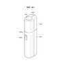
[0022] Фиг. 1 содержит схему, показывающую пример устройства генерирования аэрозоля.[0022] FIG. 1 is a diagram showing an example of an aerosol generating apparatus.
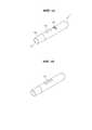
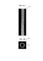
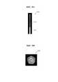
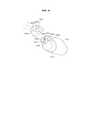
[0023] Фиг. 2 содержит схему для раскрытия примера нагревателя.[0023] FIG. 2 contains a diagram for disclosing an example of a heater.
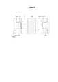
[0024] Фиг. 3 содержит схему для раскрытия примера ступенчатой поверхности, показанной на фиг. 2.[0024] FIG. 3 contains a diagram for disclosing an example of the stepped surface shown in FIG. 2.
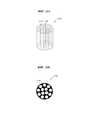
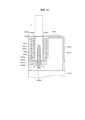
[0025] Фиг. 4 содержит схему для раскрытия примера электропроводящих дорожек.[0025] FIG. 4 contains a diagram for disclosing an example of electrically conductive tracks.
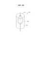
[0026] Фиг. 5 содержит схему для раскрытия примера, в котором соединены нагреватель, аккумулятор и блок управления, показанные на фиг. 1.[0026] FIG. 5 contains a diagram for disclosing an example in which the heater, battery, and control unit shown in FIG. one.
[0027] Фиг. 6A и фиг. 6B содержат схемы, показывающие различные виды примера держателя.[0027] FIG. 6A and FIG. 6B are diagrams showing various views of an example of a holder.
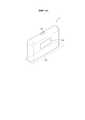
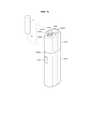
[0028] Фиг. 7 содержит схему, показывающую пример конструкции подставки.[0028] FIG. 7 is a diagram showing an example of a stand structure.
[0029] Фиг. 8A и фиг. 8B содержат схемы, показывающие различные виды примера подставки.[0029] FIG. 8A and FIG. 8B contains diagrams showing various views of an example stand.
[0030] Фиг. 9 содержит схему, показывающую пример, в котором держатель вставлен в подставку.[0030] FIG. 9 contains a diagram showing an example in which the holder is inserted into the stand.
[0031] Фиг. 10 содержит схему, показывающую пример, в котором держатель наклонен, когда вставляется в подставку.[0031] FIG. 10 contains a diagram showing an example in which the holder is tilted when inserted into the stand.
[0032] Фиг. 11 содержит схему для раскрытия примера курения с использованием держателя, наклоненного в подставке.[0032] FIG. 11 is a diagram for disclosing an example of smoking using a holder tilted in a stand.
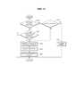
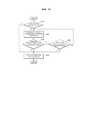
[0033] Фиг. 12 содержит блок-схему способа подсчета количества затяжек, когда держатель наклонен и отделен.[0033] FIG. 12 contains a flow chart of a method for counting the number of puffs when the holder is tilted and detached.
[0034] Фиг. 13 содержит блок-схему способа измерения времени работы, когда держатель наклонен и отделен.[0034] FIG. 13 contains a flowchart of a method for measuring the operating time when the holder is tilted and separated.
[0035] Фиг. 14 содержит схему для раскрытия примера, когда держатель подсчитывает количество затяжек.[0035] FIG. 14 contains a diagram for disclosing an example where the holder counts the number of puffs.
[0036] Фиг. 15 содержит схему для раскрытия другого примера, когда держатель подсчитывает количество затяжек.[0036] FIG. 15 contains a diagram for disclosing another example when the holder counts the number of puffs.
[0037] Фиг. 16 содержит схему для раскрытия еще одного примера, когда держатель подсчитывает количество затяжек.[0037] FIG. 16 contains a diagram for disclosing another example when the holder counts the number of puffs.
[0038] Фиг. 17 содержит схему для раскрытия способа, с помощью которого держатель измеряет время работы.[0038] FIG. 17 contains a diagram for disclosing a method by which the holder measures operating time.
[0039] Фиг. 18A - фиг. 18B содержат схемы, показывающие примеры, в которых держатель вставлен в подставку.[0039] FIG. 18A to FIG. 18B contains diagrams showing examples in which the holder is inserted into the stand.
[0040] Фиг. 19 содержит блок-схему для раскрытия примера, в котором работают держатель и подставка.[0040] FIG. 19 contains a block diagram for disclosing an example in which the holder and stand operate.
[0041] Фиг. 20 содержит блок-схему для раскрытия другого примера, в котором работает держатель.[0041] FIG. 20 contains a block diagram for disclosing another example in which the holder operates.
[0042] Фиг. 21 содержит блок-схему для раскрытия примера, в котором работает подставка.[0042] FIG. 21 contains a block diagram for disclosing an example in which the cradle operates.
[0043] Фиг. 22 содержит схему, показывающую пример, в котором сигарета вставлена в держатель.[0043] FIG. 22 is a diagram showing an example in which a cigarette is inserted into the holder.
[0044] Фиг. 23A и фиг. 23B содержат схемы, показывающие примеры сигарет.[0044] FIG. 23A and FIG. 23B contains diagrams showing examples of cigarettes.
[0045] Фиг. 24A и фиг. 24B содержат схемы для раскрытия примеров пучка волокон.[0045] FIG. 24A and FIG. 24B contain diagrams for disclosing examples of a fiber bundle.
[0046] Фиг. 25 содержит схему для раскрытия еще одного примера пучка волокон.[0046] FIG. 25 contains a diagram for disclosing yet another example of a fiber bundle.
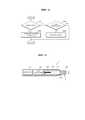
[0047] Фиг. 26A и фиг. 26B содержат схемы для раскрытия примера охлаждающей структуры, включающей в себя один вертикальный канал.[0047] FIG. 26A and FIG. 26B contains diagrams for disclosing an example of a cooling structure including one vertical channel.
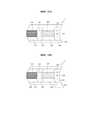
[0048] Фиг. 27A - фиг. 27C содержат схемы для раскрытия другого примера охлаждающей структуры, включающей в себя один вертикальный канал.[0048] FIG. 27A to FIG. 27C contains diagrams for disclosing another example of a cooling structure including a single vertical channel.
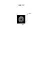
[0049] Фиг. 28A и фиг. 28B содержат схемы для раскрытия еще одного примера охлаждающей структуры, включающей в себя один вертикальный канал.[0049] FIG. 28A and FIG. 28B contains diagrams for disclosing yet another example of a cooling structure including a single vertical channel.
[0050] Фиг. 29 содержит схему для раскрытия примера охлаждающей структуры, внутренняя часть которой заполнена.[0050] FIG. 29 contains a diagram for disclosing an example of a cooling structure, the interior of which is filled.
[0051] Фиг. 30A и фиг. 30B содержат схемы для раскрытия другого примера охлаждающей структуры, внутренняя часть которой заполнена.[0051] FIG. 30A and FIG. 30B contains diagrams for disclosing another example of a cooling structure, the interior of which is filled.
[0052] Фиг. 31 содержит схему для раскрытия еще одного примера охлаждающей структуры, внутренняя часть которой заполнена.[0052] FIG. 31 contains a diagram for disclosing yet another example of a cooling structure, the interior of which is filled.
[0053] Фиг. 32A и фиг. 32B содержат схемы для раскрытия примера охлаждающей структуры, включающей в себя множество каналов.[0053] FIG. 32A and FIG. 32B contains diagrams for disclosing an example of a cooling structure including a plurality of channels.
[0054] Фиг. 33 содержит схему для раскрытия примера, в котором внутренняя часть охлаждающей структуры, включающей в себя множество каналов, заполнена.[0054] FIG. 33 contains a diagram for disclosing an example in which the interior of a cooling structure including a plurality of channels is filled.
[0055] Фиг. 34A - фиг. 34E содержат схемы для раскрытия другого примера охлаждающей структуры, включающей в себя множество каналов.[0055] FIG. 34A - FIG. 34E contains diagrams for disclosing another example of a cooling structure including a plurality of channels.
[0056] Фиг. 35 содержит схему для раскрытия примера охлаждающей структуры листового типа.[0056] FIG. 35 contains a diagram for disclosing an example of a sheet-type cooling structure.
[0057] Фиг. 36A и фиг. 36B содержат схемы для раскрытия другого примера охлаждающей структуры листового типа.[0057] FIG. 36A and FIG. 36B contains diagrams for disclosing another example of a sheet-type cooling structure.
[0058] Фиг. 37 содержит схему для раскрытия примера охлаждающей структуры гранулированного типа.[0058] FIG. 37 is a diagram for disclosing an example of a granular type cooling structure.
[0059] Фиг. 38A - фиг. 38C содержат схемы для раскрытия примера охлаждающей структуры, изготовленной в виде вложенного объекта.[0059] FIG. 38A - FIG. 38C contains diagrams for disclosing an example of a nested object cooling structure.
[0060] Фиг. 39 представляет собой вид сбоку устройства генерирования аэрозоля в соответствии с другим вариантом осуществления изобретения.[0060] FIG. 39 is a side view of an aerosol generating apparatus according to another embodiment of the invention.
[0061] Фиг. 40A содержит вид в перспективе устройства генерирования аэрозоля, согласно варианту осуществления изобретения, показанному на фиг. 39.[0061] FIG. 40A comprises a perspective view of an aerosol generating apparatus according to the embodiment of the invention shown in FIG. 39.
[0062] Фиг. 40B содержит вид в перспективе, иллюстрирующий рабочее состояние устройства генерирования аэрозоля, согласно варианту осуществления изобретения, показанному на фиг. 40A.[0062] FIG. 40B is a perspective view illustrating an operating state of an aerosol generating apparatus according to the embodiment shown in FIG. 40A.
[0063] Фиг. 41A содержит вид сбоку, иллюстрирующий другое рабочее состояние устройства генерирования аэрозоля, согласно варианту осуществления изобретения, показанному на фиг. 40A.[0063] FIG. 41A is a side view illustrating another operating state of the aerosol generating apparatus according to the embodiment shown in FIG. 40A.
[0064] Фиг. 41B содержит вид сбоку, иллюстрирующий другое рабочее состояние устройства генерирования аэрозоля, согласно варианту осуществления изобретения, показанному на фиг. 40A.[0064] FIG. 41B includes a side view illustrating another operating state of the aerosol generating apparatus according to the embodiment of the invention shown in FIG. 40A.
[0065] Фиг. 42 содержит вид сбоку, иллюстрирующий еще одно рабочее состояние устройства генерирования аэрозоля, согласно варианту осуществления изобретения, показанному на фиг. 40A.[0065] FIG. 42 is a side view illustrating yet another operating state of the aerosol generating apparatus according to the embodiment shown in FIG. 40A.
[0066] Фиг. 43 содержит вид в перспективе под другим углом устройства генерирования аэрозоля согласно варианту осуществления изобретения в состоянии, показанном на фиг. 42.[0066] FIG. 43 comprises a perspective view from another angle of an aerosol generating apparatus according to an embodiment of the invention in the state shown in FIG. 42.
[0067] Фиг. 44 содержит вид сверху некоторых элементов устройства генерирования аэрозоля согласно варианту осуществления изобретения, показанному на фиг. 43.[0067] FIG. 44 is a top plan view of some elements of an aerosol generating apparatus according to the embodiment of the invention shown in FIG. 43.
[0068] Фиг. 45 вид в перспективе под другим углом устройства генерирования аэрозоля, согласно варианту осуществления изобретения, показанному на фиг. 42.[0068] FIG. 45 is a perspective view from another angle of an aerosol generating apparatus according to the embodiment shown in FIG. 42.
[0069] Фиг. 46 содержит вид сбоку в разрезе частей некоторых элементов устройства генерирования аэрозоля в соответствии с вариантом осуществления изобретения, показанным на фиг. 41.[0069] FIG. 46 contains a side sectional view of portions of certain elements of an aerosol generating apparatus in accordance with the embodiment of the invention shown in FIG. 41.
[0070] Фиг. 47 содержит увеличенный вид согласно варианту осуществления изобретения, показанному на фиг. 46, показывающий поток воздуха за счет увеличения масштаба представления части устройства генерирования аэрозоля.[0070] FIG. 47 contains an enlarged view according to the embodiment of the invention shown in FIG. 46 showing air flow by zooming in on a portion of the aerosol generating apparatus.
[0071] Фиг. 48 содержит еще более увеличенный вид части устройства генерирования аэрозоля, согласно варианту осуществления изобретения, показанному на фиг. 47.[0071] FIG. 48 comprises an even more enlarged view of a portion of an aerosol generating apparatus according to the embodiment of the invention shown in FIG. 47.
[0072] Фиг. 49 содержит вид сбоку в разрезе части устройства генерирования аэрозоля, в соответствии с другим вариантом осуществления изобретения.[0072] FIG. 49 contains a side sectional view of a portion of an aerosol generating apparatus in accordance with another embodiment of the invention.
[0073] Фиг. 50 содержит вид сбоку в разрезе части устройства генерирования аэрозоля, в соответствии с еще одним вариантом осуществления изобретения.[0073] FIG. 50 contains a side sectional view of a portion of an aerosol generating apparatus in accordance with another embodiment of the invention.
[0074] Фиг. 51 содержит вид сбоку в разрезе части устройства генерирования аэрозоля, в соответствии с еще одним вариантом осуществления изобретения.[0074] FIG. 51 contains a side sectional view of a portion of an aerosol generating apparatus according to another embodiment of the invention.
[0075] Фиг. 52 содержит увеличенный вид сбоку в разрезе части устройства генерирования аэрозоля, в соответствии с другим вариантом осуществления изобретения.[0075] FIG. 52 contains an enlarged sectional side view of a portion of an aerosol generating apparatus according to another embodiment of the invention.
[0076] Фиг. 53 содержит вид в перспективе, иллюстрирующий рабочее состояние устройства генерирования аэрозоля в соответствии с другим вариантом осуществления изобретения.[0076] FIG. 53 is a perspective view illustrating an operating state of an aerosol generating apparatus according to another embodiment of the invention.
[0077] Фиг. 54 содержит вид в перспективе, показывающий рабочее состояние устройства генерирования аэрозоля, согласно варианту осуществления изобретения, показанному на фиг. 53, где из указанного устройства удалены некоторые элементы.[0077] FIG. 54 comprises a perspective view showing an operating state of an aerosol generating apparatus according to the embodiment shown in FIG. 53, where some elements have been removed from the specified device.
[0078] Фиг. 55 содержит вид сбоку в разрезе некоторых элементов в устройстве генерирования аэрозоля, показанном на фиг. 54.[0078] FIG. 55 contains a side sectional view of some of the elements in the aerosol generating device shown in FIG. 54.
[0079] Фиг. 56 содержит вид в перспективе, показывающий рабочее состояние устройства генерирования аэрозоля, согласно варианту осуществления изобретения, показанному на фиг. 53, где из указанного устройства удалены некоторые элементы.[0079] FIG. 56 is a perspective view showing an operating state of an aerosol generating apparatus according to the embodiment of the invention shown in FIG. 53, where some elements have been removed from the specified device.
[0080] Фиг. 57 содержит вид в перспективе снизу некоторых элементов устройства генерирования аэрозоля в соответствии с вариантом осуществления изобретения, показанным на фиг. 54.[0080] FIG. 57 comprises a bottom perspective view of certain elements of an aerosol generating apparatus in accordance with the embodiment shown in FIG. 54.
[0081] Фиг. 58 содержит диаграмму, иллюстрирующую рабочее состояние, когда используются некоторые элементы, показанные на фиг. 57.[0081] FIG. 58 contains a diagram illustrating an operating state when some of the elements shown in FIG. 57.
СУЩНОСТЬ ИЗОБРЕТЕНИЯSUMMARY OF THE INVENTION
[0082] Согласно варианту настоящего изобретения предложена система генерирования аэрозоля, которая включает в себя держатель, сконфигурированный для генерирования аэрозоля посредством нагревания сигареты; и подставку, содержащую внутреннее пространство, в которое может быть вставлен держатель, причем держатель может быть вставлен во внутреннее пространство подставки и затем может быть наклонен для образования аэрозоля.[0082] According to an embodiment of the present invention, there is provided an aerosol generating system that includes a holder configured to generate an aerosol by heating a cigarette; and a pedestal having an interior space into which the holder can be inserted, the holder being inserted into the inner space of the holder and then tilting to form an aerosol.
[0083] В раскрытой выше системе генерирования аэрозоля держатель может быть наклонен под углом, равным или превышающим 5°, и меньшим или равным 90°, когда держатель вставляют в подставку.[0083] In the above disclosed aerosol generation system, the holder can be tilted at an angle equal to or greater than 5 ° and less than or equal to 90 ° when the holder is inserted into the stand.
[0084] В раскрытой выше системе генерирования аэрозоля, когда держатель наклонен, держатель может нагревать нагреватель, входящий в состав держателя, с использованием энергии, получаемой от аккумулятора, который входит в состав подставки.[0084] In the above-disclosed aerosol generating system, when the holder is tilted, the holder can heat a heater included in the holder using energy from a battery included in the stand.
[0085] В соответствии с другим объектом настоящего раскрытия предложен нагреватель, содержащий нагревательный блок, включающий в себя базовую часть, имеющую трубчатую форму, и концевой участок, образованный на одном конце базовой части; первый лист, включающий в себя множество электропроводящих дорожек, соответственно сформированных на обеих поверхностях, окружающих, по меньшей мере, фрагмент внешней окружной поверхности базовой части; второй лист, окружающий, по меньшей мере, фрагмент первого листа и обладающий жесткостью; и слой покрытия, сконфигурированный для выравнивания ступенчатой поверхности, образованной сложенной структурой, содержащей нагревательный блок, первый лист и второй лист.[0085] In accordance with another aspect of the present disclosure, there is provided a heater comprising a heating unit including a base portion having a tubular shape and an end portion formed at one end of the base portion; a first sheet including a plurality of electrically conductive tracks respectively formed on both surfaces surrounding at least a portion of the outer circumferential surface of the base portion; a second sheet surrounding at least a portion of the first sheet and having rigidity; and a coating layer configured to flatten a stepped surface formed by a folded structure including a heating unit, a first sheet and a second sheet.
[0086] В раскрытом выше нагревателе слой покрытия содержит термостойкое вещество.[0086] In the above-disclosed heater, the coating layer contains a heat-resistant substance.
[0087] В раскрытом выше нагревателе множество электропроводящих дорожек содержит первую электропроводящую дорожку, сформированную на первой поверхности из числа обеих поверхностей первого листа и имеющую характеристику температурного коэффициента сопротивления, используемую для определения температуры нагревательного блока; и вторую электропроводящую дорожку, сформированную на второй поверхности из числа обеих поверхностей первого листа и сконфигурированную для нагрева нагревательного блока, когда по ней течет ток.[0087] In the above-disclosed heater, a plurality of electrically conductive tracks comprises a first electrically conductive track formed on a first surface of both surfaces of the first sheet and having a temperature coefficient of resistance characteristic used to determine the temperature of the heating block; and a second electrically conductive track formed on a second surface of both surfaces of the first sheet and configured to heat the heating unit when current flows therethrough.
[0088] В качестве еще одного объекта настоящего изобретения предложена система генерирования аэрозоля, содержащая держатель, сконфигурированный для генерирования аэрозоля посредством нагревания вставленной сигареты, когда сигарета вставлена; и подставку, содержащую внутреннее пространство для размещения держателя, причем держатель имеет возможность быть наклоненным вместе с внутренним пространством таким образом, что сигарета может быть вставлена в держатель, когда держатель размещен во внутреннем пространстве, причем держатель может совокупно отслеживать последовательность курения в первом состоянии, в котором держатель наклонен в подставке, и во втором состоянии, в котором держатель отделен от подставки, и может определять, удовлетворяет ли совокупно отслеживаемая последовательность курения условию ограничения курения.[0088] As another aspect of the present invention, there is provided an aerosol generating system comprising a holder configured to generate an aerosol by heating an inserted cigarette when the cigarette is inserted; and a stand comprising an interior space for receiving the holder, the holder being able to tilt with the inner space so that a cigarette can be inserted into the holder when the holder is placed in the inner space, the holder can collectively track a smoking sequence in the first state, in in which the holder is tilted in the stand, and in a second state in which the holder is separated from the stand, and can determine whether the cumulatively monitored smoking sequence satisfies the smoking restriction condition.
[0089] В описанной выше системе генерирования аэрозоля держатель может накапливать последовательность курения, отслеживаемую во втором состоянии, и добавлять ее к последовательности курения, отслеживаемой в первом состоянии, когда курение выполняется в первом состоянии и впоследствии выполняется во втором состоянии позже, и держатель может управлять нагревателем, предусмотренным в держателе, для прекращения нагрева вставленной сигареты, когда накопленная последовательность курения удовлетворяет условию ограничения курения.[0089] In the above-described aerosol generation system, the holder can accumulate the smoking sequence tracked in the second state and add it to the smoking sequence tracked in the first state when smoking is performed in the first state and subsequently performed in the second state later, and the holder can control a heater provided in the holder for stopping heating of the inserted cigarette when the accumulated smoking sequence satisfies the smoking restriction condition.
[0090] В описанной выше системе генерирования аэрозоля держатель может накапливать последовательность курения, отслеживаемую в первом состоянии, и добавлять ее к последовательности курения, отслеживаемой во втором состоянии, когда курение выполняется во втором состоянии и впоследствии выполняется в первом состоянии позже, и держатель может управлять нагревателем, предусмотренным в держателе, для прекращения нагрева вставленной сигареты, когда накопленная последовательность курения удовлетворяет условию ограничения курения.[0090] In the above-described aerosol generation system, the holder can accumulate the smoking sequence tracked in the first state and add it to the smoking sequence tracked in the second state when smoking is performed in the second state and subsequently performed in the first state later, and the holder can control a heater provided in the holder for stopping heating of the inserted cigarette when the accumulated smoking sequence satisfies the smoking restriction condition.
[0091] В качестве еще одного объекта настоящего изобретения предлагается устройство генерирования аэрозоля, которое содержит корпус; полую выступающую трубку, выступающую из первого конца корпуса и содержащую отверстие, открытое наружу; нагреватель, установленный в корпусе таким образом, что концевой участок нагревателя расположен внутри выступающей трубки, и он выполнен с возможностью генерирования тепла при подаче электрического сигнала; и выступающую часть, которая содержит боковую стенку, образующую приемный канал для размещения сигареты; отверстие для вставки, открытое наружу на одном конце приемного канала для введения в него сигареты; и донную стенку, сконфигурированную для закрытия другого конца приемного канала и содержащую отверстие нагревателя, через которое проходит концевой участок нагревателя, причем вмещающая часть выполнена с возможностью быть вставленной в выступающую трубку или быть отделенной от выступающей трубки.[0091] As another aspect of the present invention, there is provided an aerosol generating apparatus that includes a housing; a hollow protruding tube projecting from the first end of the housing and containing an opening that is open to the outside; a heater installed in the housing such that an end portion of the heater is located inside the protruding tube and is configured to generate heat when an electrical signal is applied; and a projecting portion that includes a side wall defining a receiving channel for receiving a cigarette; an insertion hole opening outwardly at one end of the receiving channel for inserting a cigarette therein; and a bottom wall configured to cover the other end of the receiving channel and comprising a heater opening through which the heater end portion extends, the receiving portion being configured to be inserted into the protruding tube or be separated from the protruding tube.
[0092] Устройство генерирования аэрозоля, описанное выше, дополнительно содержит крышку, которая содержит внешнее отверстие, способное обеспечивать доступ снаружи к отверстию для вставки, которое входит в состав вмещающей части, и, кроме того, указанная крышка может быть присоединена к первому концевому участку корпуса для закрытия вмещающей части и может быть снята с корпуса.[0092] The aerosol generating apparatus described above further comprises a cover that includes an external opening capable of externally accessing the insertion opening that is part of the receiving portion, and furthermore, the cover can be attached to the first end portion of the body to close the enclosing part and can be removed from the body.
[0093] В раскрытом выше устройстве генерирования аэрозоля зазор для введения наружного воздуха, который позволяет воздуху снаружи крышки поступать в крышку, образован на участке, где крышка и корпус прикреплены друг к другу, вмещающая часть дополнительно включает в себя наружную стенку, окружающую боковую стенку и отделена от боковой стенки наружу в радиальном направлении боковой стенки, вмещающая часть и выступающая трубка могут быть соединены друг с другом посредством вставки выступающей трубки между наружной стенкой и боковой стенкой, при этом воздушный зазор для подачи воздуха образован на участке, где наружная стенка вмещающей части и выступающая трубка прикреплены друг к другу, что позволяет воздуху из пространства вокруг вмещающей части проходить во вмещающую часть, и выступающая трубка дополнительно содержит отверстие для воздуха, через которое воздух может проходить к концевому участку сигареты, размещенной во вмещающей части.[0093] In the above-disclosed aerosol generating apparatus, a gap for introducing outside air that allows air from outside the lid to enter the lid is formed at a portion where the lid and the body are attached to each other, the receiving portion further includes an outer wall surrounding the side wall, and is separated from the side wall outwardly in the radial direction of the side wall, the receiving portion and the protruding tube may be connected to each other by inserting the protruding tube between the outer wall and the side wall, wherein an air gap is formed at a portion where the outer wall of the receiving portion and the protruding tube is attached to each other to allow air from the space around the receiving portion to pass into the receiving portion, and the protruding tube further comprises an air opening through which air can flow to the end portion of the cigarette housed in the receiving portion.
[0094] В качестве еще одного объекта настоящего изобретения предложено генерирующее аэрозоль изделие для генерирования аэрозоля в сочетании с устройством генерирования аэрозоля, причем генерирующее аэрозоль изделие содержит табачный стержень и охлаждающую конструкцию, изготовленную посредством плетения, по меньшей мере, одного пучка волокон.[0094] As yet another aspect of the present invention, there is provided an aerosol generating article for generating an aerosol in combination with an aerosol generating device, the aerosol generating article comprising a tobacco rod and a cooling structure made by braiding at least one fiber bundle.
[0095] В описанном выше генерирующем аэрозоль изделии пучок волокон изготовлен с использованием биоразлагаемого полимерного материала, и биоразлагаемый полимерный материал может содержать, по меньшей мере, одно вещество из следующих веществ: полимолочная кислота (PLA), полигидроксибутират (PHB), ацетат целлюлозы, поли-эпсилон- капролактон (PCL), полигликолевая кислота (PGA), полигидроксиалканоат (PHAs) и термопластичные полимеры на основе крахмала.[0095] In the above aerosol generating article, the fiber bundle is made using a biodegradable polymeric material, and the biodegradable polymeric material may contain at least one of the following substances: polylactic acid (PLA), polyhydroxybutyrate (PHB), cellulose acetate, poly - epsilon - caprolactone (PCL), polyglycolic acid (PGA), polyhydroxyalkanoate (PHAs) and starch-based thermoplastic polymers.
[0096] В описанном выше генерирующем аэрозоль изделии пучок волокон изготавливают посредством сплетения, по меньшей мере, одной нити волокна.[0096] In the above-described aerosol generating article, a bundle of fibers is produced by weaving at least one strand of fiber.
ВАРИАНТЫ осуществления изобретенияVARIANTS OF THE INVENTION
[0097] Что касается терминов в различных примерах осуществления настоящего изобретения, общие термины, которые в настоящее время и широко используются, выбираются с учетом функций структурных элементов в различных вариантах осуществления настоящего изобретения. Однако значения терминов могут быть изменены в соответствии с намерением, судебным прецедентом, появлением новой технологии и тому подобным. Кроме того, в некоторых случаях может быть выбран термин, который обычно не используется. В таком случае значение термина будет подробно раскрыто в соответствующей части настоящего описания. Следовательно, термины, используемые в различных вариантах осуществления настоящего изобретения, должны быть определены на основе значений терминов и описаний, представленных в настоящем документе.[0097] With regard to terms in various embodiments of the present invention, general terms that are currently and widely used are selected in consideration of the functions of the building blocks in various embodiments of the present invention. However, the meanings of the terms can be changed in accordance with intent, legal precedent, new technology, and the like. In addition, in some cases, a term may be chosen that is not normally used. In such a case, the meaning of the term will be disclosed in detail in the relevant part of this description. Therefore, terms used in various embodiments of the present invention should be defined based on the meanings of the terms and descriptions presented herein.
[0098] Кроме того, если прямо не указано обратное, слово «содержать» и его формы, такие как «содержит» или «содержащий», означают нахождение указанных элементов в составе чего-либо, но не исключение любых других элементов. Кроме того, термины «блок», «часть» и «модуль», указанные в раскрытии, означают блоки для обработки, по меньшей мере, одной функции и операции и могут быть реализованы аппаратными компонентами или программными компонентами, а также их комбинациями.[0098] In addition, unless expressly stated otherwise, the word "comprise" and its forms, such as "contains" or "containing", mean that the specified elements are included in something, but not exclude any other elements. In addition, the terms "block", "part", and "module" referred to in the disclosure mean blocks for processing at least one function and operation and may be implemented by hardware components or software components, as well as combinations thereof.
[0099] Примеры и варианты осуществления настоящего изобретения будут подробно раскрыты ниже со ссылкой на сопутствующие чертежи. Однако изобретение может быть реализовано во многих различных формах и не должно рассматриваться как ограничение посредством изложенных здесь вариантов осуществления изобретения.[0099] Examples and embodiments of the present invention will be described in detail below with reference to the accompanying drawings. However, the invention may be embodied in many different forms and should not be construed as limiting by the embodiments set forth herein.
[00100] Ниже по тексту будут подробно раскрыты некоторые варианты осуществления предложенного изобретения со ссылкой на прилагаемые фигуры.[00100] Hereinafter, some embodiments of the present invention will be described in detail with reference to the accompanying figures.
[00101] Фиг. 1 содержит схему, показывающую пример устройства генерирования аэрозоля.[00101] FIG. 1 is a diagram showing an example of an aerosol generating apparatus.
[00102] На фиг. 1 устройство 1 генерирования аэрозоля (далее называемое «держатель») включает в себя аккумулятор 110, блок 120 управления и нагреватель 130. Держатель 1 также включает в себя внутреннее пространство, образованное корпусом 140. Сигарета может быть вставлена во внутреннее пространство держателя 1.[00102] FIG. 1, an aerosol generating device 1 (hereinafter referred to as a "holder") includes a
[00103] В держателе 1 показаны только элементы, относящиеся к настоящему варианту осуществления изобретения, показанному на фиг. 1. Следовательно, специалисту в данной области техники будет понятно, что общие элементы, отличные от элементов, показанных на фиг. 1, могут быть дополнительно включены в состав держателя 1.[00103] In the
[00104] Когда сигарета вставлена в держатель 1, держатель 1 обеспечивает нагрев нагревателя 130. Температура материала, способного генерировать аэрозоль, в сигарете повышается с помощью нагреваемого нагревателя 130, и, таким образом, образуется аэрозоль. Генерируемый аэрозоль доставляется пользователю через сигаретный фильтр. Однако даже когда сигарета не вставлена в держатель 1, держатель 1 может обеспечивать нагрев нагревателя 130.[00104] When the cigarette is inserted into the
[00105] Корпус 140 может быть отсоединен от держателя 1. Например, когда пользователь поворачивает корпус 140 по часовой стрелке или против часовой стрелки, корпус 140 может быть отсоединен от держателя 1.[00105] The
[00106] Диаметр отверстия, образованного концом 141 корпуса 140, может быть меньше диаметра пространства, образованного корпусом 140 в зоне нагревателя 130. В этом случае отверстие может служить направляющей для сигареты, вставленной в держатель 1.[00106] The diameter of the hole formed by the
[00107] Аккумулятор 110 подает энергию, используемую держателем 1 для работы. Например, аккумулятор 110 может подавать энергию для нагревания нагревателя 130 и подавать энергию для работы блока 120 управления. Кроме того, аккумулятор 110 может подавать питание для работы дисплея, датчика, электродвигателя и т.п., установленных в держателе 1.[00107] The
[00108] Аккумулятор 110 может представлять собой литий-железо-фосфатный (LiFePO4) аккумулятор, но без ограничения этим примером. Например, аккумулятор 110 может представлять собой литиево-кобальто-оксидный (LiCoO2) аккумулятор, литиево-титанатный аккумулятор и т.д.[00108] The
[00109] Кроме того, аккумулятор 110 может иметь цилиндрическую форму диаметром 10 мм и длиной 37 мм, но без ограничения этим примером. Емкость аккумулятора 110 может составлять 120 мАч или более, и аккумулятор 110 может представлять собой перезаряжаемый аккумулятор или одноразовую батарею. Например, когда аккумулятор 110 является перезаряжаемым, скорость заряда (C-скорость) аккумулятора 110 может составлять 10C, а скорость разряда (C-скорость) может составлять от 16C до 20C. Однако настоящее изобретение этим не ограничено. Кроме того, для стабильного использования аккумулятор 110 может быть изготовлен так, что 80 % или более от общей емкости может быть обеспечено даже тогда, когда заряд/разряд выполняется 8000 раз.[00109] In addition, the
[00110] При этом на основании уровня мощности, накопленной в аккумуляторе 110, может быть определено, полностью ли заряжен аккумулятор 110 или полностью разряжен по сравнению со всей емкостью аккумулятора 110. Например, когда мощность, накопленная в аккумуляторе 110, равна или превышает 95 % общей емкости, может быть определено, что аккумулятор 110 полностью заряжен. Кроме того, когда мощность, запасенная в аккумуляторе 110, составляет 10 % или менее от общей емкости, может быть определено, что аккумулятор 110 полностью разряжен. Однако критерии для определения того, полностью ли заряжен аккумулятор 110 или полностью разряжен, не ограничиваются приведенными выше примерами.[00110] Here, based on the level of power stored in the
[00111] Нагреватель 130 может нагреваться за счет энергии, подаваемой от аккумулятора 110. Когда сигарета вставлена в держатель 1, нагреватель 130 расположен внутри сигареты. Следовательно, нагретый нагреватель 130 может повышать температуру материала, способного генерировать аэрозоль, в сигарете.[00111] The
[00112] Форма нагревателя 130 может быть комбинацией цилиндрической формы и конической формы. Диаметр нагревателя 130 может быть соответствующим образом выбран в диапазоне от 2 мм до 3 мм. Предпочтительно, нагреватель 130 может быть изготовлен так, чтобы иметь диаметр 2,15 мм, но без ограничения этим примером. Кроме того, нагреватель 130 может иметь подходящую длину в диапазоне от 20 мм до 30 мм. Предпочтительно, нагреватель 130 может быть изготовлен так, чтобы иметь длину 19 мм, но без ограничения этим примером. Кроме того, конец 131 нагревателя 130 может быть выполнен с формой в виде острого угла, но без ограничения этим примером. Другими словами, нагреватель 130 может иметь любую форму, при условии, что нагреватель 130 может быть вставлен в сигарету. Кроме того, может быть нагрета только часть нагревателя 130. Например, если предположить, что длина нагревателя 130 составляет 19 мм, только 12 мм от конца 131 нагревателя 130 могут быть нагреты, а оставшаяся часть нагревателя 130 может не нагреваться.[00112] The shape of the
[00113] Нагреватель 130 может представлять собой электрорезистивный нагреватель. Например, нагреватель 130 включает в себя электропроводящую дорожку, и нагреватель 130 может нагреваться, когда ток протекает через электропроводящую дорожку.[00113] The
[00114] Для стабильного использования нагреватель 130 может получать питание в соответствии со спецификациями 3,2 В, 2,4 А и 8 Вт, но без ограничения этим примером. Например, когда питание подается на нагреватель 130, температура поверхности нагревателя 130 может повышаться до 400 °C или выше. Температура поверхности нагревателя 130 может повыситься приблизительно до 350 °С через 15 секунд после начала подачи питания на нагреватель 130.[00114] For stable use, the
[00115] Далее конструкция нагревателя 130 будет подробно раскрыта со ссылкой на фиг. 2 - фиг. 5.[00115] Next, the structure of the
[00116] Фиг. 2 содержит схему для пояснения примера нагревателя.[00116] FIG. 2 contains a diagram for explaining an example of a heater.
[00117] Как показано на фиг. 2, нагреватель 130 может включать в себя нагревательный блок 1315, первый лист 1325, окружающий часть нагревательного блока 1315, второй лист 1335, защищающий первый лист 1325, и слой 1345 покрытия.[00117] As shown in FIG. 2,
[00118] Согласно примеру осуществления изобретения нагревательный блок 1315 может иметь форму иглы (например, комбинацию цилиндрической формы и конической формы). Кроме того, нагревательный блок 1315 может включать в себя базовую часть и концевую часть. Например, базовая часть нагревательного блока 1315 может иметь цилиндрическую форму, но без ограничения этим примером. Кроме того, концевая часть нагревательного блока 1315 может быть сформирована на одном конце базовой части, чтобы облегчить введение в образующий аэрозоль материал. В частности, базовая часть и концевая часть могут быть сформированы как одно целое. В качестве альтернативы, базовая часть и концевая часть могут быть изготовлены отдельно, а затем приклеены друг к другу.[00118] According to an exemplary embodiment, the heating block 1315 may be in the shape of a needle (eg, a combination of a cylindrical shape and a conical shape). In addition, the heating block 1315 may include a base portion and an end portion. For example, the base portion of the heater block 1315 may be cylindrical in shape, but not limited to this example. In addition, an end portion of the heating block 1315 may be formed at one end of the base portion to facilitate insertion into the aerosol-generating material. In particular, the base portion and the end portion can be formed as one piece. Alternatively, the base part and the end part can be made separately and then glued to each other.
[00119] Нагревательный блок 1315 может содержать теплопроводный материал. Например, теплопроводящий материал может содержать керамику, в том числе, оксид алюминия или диоксид циркония, анодированный металл, металл с покрытием, полиимид (PI) и т.д., но без ограничения этим примером.[00119] The heating block 1315 may comprise a heat-conducting material. For example, the thermally conductive material may comprise ceramics, including but not limited to alumina or zirconia, anodized metal, coated metal, polyimide (PI), etc., but not limited to this example.
[00120] Согласно примеру осуществления изобретения, первый лист 1325 может окружать, по меньшей мере, часть нагревательного блока 1315. Например, первый лист 1325 может окружать, по меньшей мере, часть наружной окружной поверхности базовой части нагревателя 130. Электропроводящие дорожки могут быть сформированы на обеих сторонах первого листа 1325.[00120] According to an exemplary embodiment, the first sheet 1325 may surround at least a portion of the heating block 1315. For example, the first sheet 1325 may surround at least a portion of the outer circumferential surface of the base portion of the
[00121] Кроме того, первая электропроводящая дорожка, сформированная на одной стороне из двух сторон первого листа 1325, может получать энергию от аккумулятора. Когда ток протекает через первую электропроводящую дорожку, температура первой электропроводящей дорожки может повышаться. Кроме того, когда температура первой электропроводящей дорожки повышается, тепло передается к нагревательному блоку 1315, смежному с первой электропроводящей дорожкой, и, таким образом, нагревательный блок 1315 может нагреваться.[00121] In addition, the first electrically conductive track formed on one side of the two sides of the first sheet 1325 can receive power from a battery. When current flows through the first electrically conductive track, the temperature of the first electrically conductive track may rise. In addition, when the temperature of the first electrically conductive track rises, heat is transferred to the heating unit 1315 adjacent to the first electrically conductive track, and thus the heating unit 1315 can be heated.
[00122] В зависимости от мощности, потребляемой сопротивлением первой электропроводящей дорожки, может быть определена температура нагрева для первой электропроводящей дорожки. Кроме того, на основании мощности, потребляемой сопротивлением первой электропроводящей дорожки, может быть установлено значение сопротивления первой электропроводящей дорожки.[00122] Depending on the power consumed by the resistance of the first electrically conductive track, a heating temperature for the first electrically conductive track may be determined. In addition, based on the power consumed by the resistance of the first electrically conductive trace, the resistance value of the first electrically conductive trace can be set.
[00123] Например, значение сопротивления первой электропроводящей дорожки может составлять от 0,5 до 1,2 Ом при комнатной температуре 25 °C, но без ограничения этим примером. В то же время значение сопротивления первой электропроводящей дорожки может быть определено на основе материала, длины, ширины, толщины и структуры первой электропроводящей дорожки.[00123] For example, the resistance value of the first electrically conductive track may be 0.5 to 1.2 ohms at a room temperature of 25 ° C, but is not limited to this example. At the same time, the resistance value of the first electrically conductive track can be determined based on the material, length, width, thickness, and structure of the first electrically conductive track.
[00124] Внутреннее сопротивление первой электропроводящей дорожки может увеличиваться при повышении ее температуры, что обусловлено характеристиками температурного коэффициента сопротивления. Например, температура первой электропроводящей дорожки может быть пропорциональна величине сопротивления первой электропроводящей дорожки в заданном температурном диапазоне.[00124] The internal resistance of the first electrically conductive track may increase as its temperature rises due to characteristics of the temperature coefficient of resistance. For example, the temperature of the first electrically conductive track may be proportional to the resistance value of the first electrically conductive track over a predetermined temperature range.
[00125] Например, заданное напряжение может быть приложено к первой электропроводящей дорожке, а ток, протекающий через первую электропроводную дорожку, может быть измерен датчиком тока. В этом случае сопротивление первой электропроводящей дорожки может быть рассчитано на основе отношения между измеренным током и приложенным напряжением. На основе вычисленного сопротивления можно оценить температуру первой электропроводящей дорожки или нагревательного блока 1315 в соответствии с характеристикой температурного коэффициента сопротивления первой электропроводящей дорожки.[00125] For example, a predetermined voltage can be applied to the first electrically conductive track, and the current flowing through the first electrically conductive track can be measured by a current sensor. In this case, the resistance of the first electrically conductive track can be calculated based on the ratio between the measured current and the applied voltage. Based on the calculated resistance, the temperature of the first electrically conductive track or heating block 1315 can be estimated in accordance with the temperature coefficient characteristic of the resistance of the first electrically conductive track.
[00126] Например, первая электропроводящая дорожка может содержать вольфрам, золото, платину, серебро, медь, никель-палладий или их комбинацию. Кроме того, первая электропроводящая дорожка может быть легирована подходящей легирующей добавкой и может содержать сплав.[00126] For example, the first electrically conductive track may contain tungsten, gold, platinum, silver, copper, nickel-palladium, or a combination thereof. In addition, the first electrically conductive track may be doped with a suitable dopant and may contain an alloy.
[00127] Одна или обе поверхности первого листа 1325 могут включать в себя вторую электропроводящую дорожку, которая имеет характеристику температурного коэффициента сопротивления и используется для определения температуры нагревательного блока 1315. Внутреннее сопротивление второй электропроводящей дорожки может увеличиваться при повышении ее температуры, что обусловлено характеристиками температурного коэффициента сопротивления. Например, температура второй электропроводящей дорожки может быть пропорциональна величине сопротивления второй электропроводящей дорожки в заданном температурном диапазоне.[00127] One or both surfaces of the first sheet 1325 may include a second electrically conductive track that has a temperature coefficient of resistance characteristic and is used to determine the temperature of the heating block 1315. The internal resistance of the second electrically conductive track may increase as its temperature rises due to the characteristics of the temperature coefficient resistance. For example, the temperature of the second electrically conductive track may be proportional to the resistance value of the second electrically conductive track over a predetermined temperature range.
[00128] Вторая электропроводящая дорожка может быть расположена рядом с нагревательным блоком 1315. Соответственно, когда температура нагревательного блока 1315 повышается, температура второй электропроводящей дорожки, смежной с ним, также может повышаться. Заданное напряжение может быть приложено ко второй электропроводящей дорожке, и ток, протекающий через вторую электропроводящую дорожку, может быть измерен детектором тока. В этом случае сопротивление второй электропроводящей дорожки может быть определено на основе отношения между измеренным током и приложенным напряжением. На основании определенного сопротивления может быть определена температура нагревательного блока 1315 в соответствии с температурным коэффициентом сопротивления, характерным для второй электропроводящей дорожки.[00128] The second electrically conductive track may be located adjacent to the heating unit 1315. Accordingly, when the temperature of the heating unit 1315 rises, the temperature of the second electrically conductive track adjacent thereto may also rise. A predetermined voltage can be applied to the second electrically conductive track, and the current flowing through the second electrically conductive track can be measured by a current detector. In this case, the resistance of the second electrically conductive track can be determined based on the ratio between the measured current and the applied voltage. Based on the determined resistance, the temperature of the heating block 1315 can be determined in accordance with the temperature coefficient of resistance characteristic of the second electrically conductive track.
[00129] В зависимости от температуры второй электропроводящей дорожки значение сопротивления второй электропроводящей дорожки может изменяться. Следовательно, на основании изменения значения сопротивления второй электропроводящей дорожки можно измерять изменение температуры второй электропроводящей дорожки. Например, значение сопротивления второй электропроводящей дорожки может составлять от 7 до 18 Ом при температуре 25 °С, но без ограничения этим примером. В то же время значение сопротивления второй электропроводящей дорожки может быть определено на основе материала, длины, ширины, толщины и структуры второй электропроводящей дорожки.[00129] Depending on the temperature of the second electrically conductive track, the resistance value of the second electrically conductive track may vary. Therefore, based on the change in the resistance value of the second electrically conductive track, the change in temperature of the second electrically conductive track can be measured. For example, the resistance value of the second electrically conductive track may be 7 to 18 ohms at a temperature of 25 ° C, but is not limited to this example. At the same time, the resistance value of the second electrically conductive track can be determined based on the material, length, width, thickness, and structure of the second electrically conductive track.
[00130] Например, вторая электропроводящая дорожка может содержать вольфрам, золото, платину, серебро, медь, никель-палладий или их комбинацию. Кроме того, вторая электропроводящая дорожка может быть легирована подходящей легирующей добавкой или может содержать сплав.[00130] For example, the second electrically conductive track may contain tungsten, gold, platinum, silver, copper, nickel-palladium, or a combination thereof. In addition, the second electrically conductive track may be doped with a suitable dopant or may contain an alloy.
[00131] Первая электропроводящая дорожка может быть соединена с аккумулятором через электрическую соединительную часть. Как раскрыто выше, когда питание подается от аккумулятора, температура первой электропроводящей дорожки может повышаться.[00131] The first electrically conductive track may be connected to a battery via an electrical connecting portion. As disclosed above, when power is supplied from a battery, the temperature of the first electrically conductive track may rise.
[00132] Вторая электропроводящая дорожка может включать в себя электрическую соединительную часть, на которую подается напряжение постоянного тока. Электрическая соединительная часть второй электропроводящей дорожки отделена от электрической соединительной части первой электропроводящей дорожки. Кроме того, когда постоянное напряжение, приложенное ко второй электропроводящей дорожке, является постоянным, величина тока, протекающего через вторую электропроводящую дорожку, может быть определена на основе сопротивления второй электропроводящей дорожки.[00132] The second electrically conductive track may include an electrical connection portion to which a DC voltage is applied. The electrical connecting portion of the second electrically conductive track is separated from the electrical connecting portion of the first electrically conductive track. In addition, when a constant voltage applied to the second electrically conductive track is constant, the amount of current flowing through the second electrically conductive track can be determined based on the resistance of the second electrically conductive track.
[00133] Вторая электропроводящая дорожка может быть подключена к операционному усилителю (ОУ). ОУ включает в себя блок питания, который получает энергию постоянного тока извне, входной блок, который электрически соединен со второй электропроводящей дорожкой и получает постоянное напряжение и/или постоянный ток, и выходной блок, который может выводить сигнал на основе постоянного напряжения и/или тока, подаваемого на входной блок.[00133] The second electrically conductive track may be connected to an operational amplifier (OA). The op amp includes a power supply that receives DC power from the outside, an input unit that is electrically connected to the second electrically conductive track and receives a DC voltage and / or DC current, and an output unit that can output a signal based on the DC voltage and / or current. supplied to the input block.
[00134] ОУ может получать постоянное напряжение через блок питания. Кроме того, ОУ может получать постоянное напряжение через входной блок. В то же время величина напряжения постоянного тока, подаваемого через входной блок ОУ, и величина напряжения постоянного тока, подаваемого через блок питания ОУ, могут быть одинаковыми. Кроме того, напряжение постоянного тока, подаваемое на входной блок ОУ, может быть равно напряжению постоянного тока, приложенному к электрической соединительной части второй электропроводящей дорожки.[00134] The op amp can receive constant voltage through the power supply. In addition, the op-amp can receive DC voltage through the input block. At the same time, the magnitude of the DC voltage supplied through the input unit of the op-amp and the magnitude of the dc voltage supplied through the power supply of the op-amp may be the same. In addition, the DC voltage supplied to the op-amp input unit may be equal to the DC voltage applied to the electrical connecting portion of the second electrically conductive track.
[00135] Электрическая соединительная часть второй электропроводящей дорожки и входной блок ОУ могут быть отделены от электрической соединительной части первой электропроводящей дорожки.[00135] The electrical connecting portion of the second electrically conductive track and the input unit OA may be separated from the electrical connecting portion of the first electrically conductive track.
[00136] Если температура второй электропроводящей дорожки изменяется, то значение сопротивления второй электропроводящей дорожки может изменяться. Таким образом, вторая электропроводящая дорожка функционирует как переменный резистор, который управляется температурой в качестве управляющей переменной, и, когда изменяется значение сопротивления второй электропроводящей дорожки, то изменяется ток, протекающий во входной блок ОУ, электрически соединенный со второй электропроводящей дорожкой. Когда сопротивление второй электропроводящей дорожки увеличивается, ток, протекающий во входной блок ОУ, электрически соединенный со второй электропроводящей дорожкой, уменьшается. В то же время, даже когда значение сопротивления второй электропроводящей дорожки изменяется, напряжение постоянного тока, приложенное к входному блоку ОУ, может оставаться постоянным.[00136] If the temperature of the second electrically conductive track changes, then the resistance value of the second electrically conductive track may change. Thus, the second electrically conductive track functions as a variable resistor that is controlled by temperature as a control variable, and when the resistance value of the second electrically conductive path changes, the current flowing to the op-amp input unit electrically connected to the second electrically conductive path changes. When the resistance of the second electrically conductive track increases, the current flowing to the op-amp input unit electrically connected to the second electrically conductive track decreases. At the same time, even when the resistance value of the second electrically conductive track changes, the DC voltage applied to the op-amp input unit can remain constant.
[00137] При изменении тока, протекающего во входной блок ОУ, напряжение и/или ток сигнала, получаемого из выходного блока ОУ, могут изменяться. Например, если входной ток ОУ увеличивается, выходное напряжение ОУ может увеличиваться. В другом примере, если входной ток ОУ увеличивается, выходное напряжение ОУ может уменьшаться.[00137] As the current flowing into the op-amp input block changes, the voltage and / or current of the signal received from the op-amp output block may change. For example, if the op amp's input current increases, the op amp's output voltage may increase. In another example, if the op amp's input current increases, the op amp's output voltage may decrease.
[00138] Соотношение между температурой и значением сопротивления второй электропроводящей дорожки, соотношение между значением сопротивления второй электропроводящей дорожки и входным током, приложенным к ОУ, и соотношение между входным током и выходным напряжением ОУ, когда на входной блок ОУ подается постоянное напряжение постоянного тока, может быть определено или получено экспериментально. Следовательно, выходное напряжение и/или изменение выходного напряжения ОУ могут быть измерены для обнаружения изменения температуры и/или изменения температуры второй электропроводящей дорожки.[00138] The relationship between the temperature and the resistance value of the second electrically conductive track, the relationship between the resistance value of the second electrically conductive track and the input current applied to the op amp, and the relationship between the input current and the op amp output voltage when a constant dc voltage is applied to the op amp input block, can be determined or obtained experimentally. Therefore, the output voltage and / or change in the output voltage of the op-amp can be measured to detect a change in temperature and / or a change in temperature of the second electrically conductive track.
[00139] Например, ОУ может иметь такую характеристику, при которой напряжение выходного блока ОУ увеличивается с увеличением входного тока, поступающего во входной блок. В этом случае температура нагревателя повышается при подаче энергии на первую электропроводящую дорожку. В результате повышается температура второй электропроводящей дорожки. В то же время, поскольку значение сопротивления второй электропроводящей дорожки увеличивается, величина входного тока, поданного на входной блок ОУ, может быть уменьшена. Следовательно, напряжение на выходном блоке ОУ уменьшается. И наоборот, напряжение на выходном блоке ОУ увеличивается, когда подача питания на первую электропроводящую дорожку прерывается или мощность, подаваемая на первую электропроводную дорожку, уменьшается, и температура нагревателя уменьшается.[00139] For example, an op-amp may have a characteristic such that the voltage of the op-amp's output block increases as the input current to the input-block increases. In this case, the temperature of the heater rises when power is applied to the first electrically conductive track. As a result, the temperature of the second electrically conductive track rises. At the same time, since the resistance value of the second electrically conductive track increases, the amount of the input current supplied to the op-amp input unit can be reduced. Consequently, the voltage at the op-amp's output block decreases. Conversely, the voltage at the op-amp output unit increases when the power supply to the first conductive track is interrupted or the power supplied to the first conductive track decreases and the temperature of the heater decreases.
[00140] В другом примере ОУ может иметь такую характеристику, при которой напряжение выходного блока ОУ уменьшается с увеличением входного тока, поступающего во входной блок. В этом случае температура нагревателя повышается при подаче энергии на первую электропроводящую дорожку. В результате повышается температура второй электропроводящей дорожки. В то же время, поскольку значение сопротивления второй электропроводящей дорожки увеличивается, величина входного тока, поданного на входной блок ОУ, может быть уменьшена. Следовательно, напряжение на выходном блоке ОУ увеличивается. И наоборот, напряжение на выходном блоке ОУ уменьшается, когда подача питания на первую электропроводящую дорожку прерывается или мощность, подаваемая на первую электропроводную дорожку, уменьшается, и температура нагревателя уменьшается.[00140] In another example, the op-amp may have a characteristic such that the voltage of the op-amp's output block decreases as the input current to the input-block increases. In this case, the temperature of the heater rises when power is applied to the first electrically conductive track. As a result, the temperature of the second electrically conductive track rises. At the same time, since the resistance value of the second electrically conductive track increases, the amount of the input current supplied to the op-amp input unit can be reduced. Consequently, the voltage at the op-amp's output block increases. Conversely, the voltage at the op-amp output unit decreases when the power supply to the first conductive track is interrupted or the power supplied to the first conductive track decreases and the temperature of the heater decreases.
[00141] Выходной блок ОУ может быть подключен к процессору. Например, процессор может представлять собой блок микроконтроллера (БМК). Процессор может определять температуру второй электропроводящей дорожки или нагревательного блока, используя значение выходного напряжения ОУ. Процессор также может регулировать напряжение питания, подаваемое на первую электропроводящую дорожку, используя значение температуры нагревательного блока.[00141] The op-amp output block may be connected to the processor. For example, the processor can be a microcontroller unit (MCU). The processor can determine the temperature of the second electrically conductive track or heating block using the value of the op-amp output voltage. The processor can also regulate the supply voltage to the first electrically conductive track using the temperature value of the heater block.
[00142] Согласно примеру осуществления изобретения, первая электропроводящая дорожка и вторая электропроводящая дорожка могут быть сформированы на обеих сторонах первого листа 1325 соответственно. Например, первая электропроводящая дорожка может быть расположена на одной стороне первого листа 1325, в контакте с нагревательным блоком 1315, и вторая электропроводящая дорожка может быть расположена на другой стороне. В другом примере вторая электропроводящая дорожка может быть расположена на одной стороне первого листа 1325, в контакте с нагревательным блоком 1315, и первая электропроводящая дорожка может быть расположена на другой стороне.[00142] According to an exemplary embodiment, a first electrically conductive track and a second electrically conductive track may be formed on both sides of the first sheet 1325, respectively. For example, the first electrically conductive track may be located on one side of the first sheet 1325 in contact with the heating block 1315, and the second electrically conductive path may be located on the other side. In another example, the second electrically conductive track may be located on one side of the first sheet 1325, in contact with the heating unit 1315, and the first electrically conductive path may be located on the other side.
[00143] Согласно другому примеру осуществления изобретения, первая электропроводящая дорожка и вторая электропроводящая дорожка могут быть расположены на одной и той же стороне первого листа 1325. Например, как первая электропроводящая дорожка, так и вторая электропроводящая дорожка могут быть расположены на той стороне из числа обеих сторон первого листа 1325, которая контактирует с нагревательным блоком 1315. В другом примере, как первая электропроводящая дорожка, так и вторая электропроводящая дорожка могут быть расположены на той стороне из числа обеих сторон первого листа 1325, которая не контактирует с нагревательным блоком 1315.[00143] According to another embodiment of the invention, the first electrically conductive track and the second electrically conductive track may be located on the same side of the first sheet 1325. For example, both the first electrically conductive track and the second electrically conductive track may be located on that side of both sides of the first sheet 1325 that contacts the heating block 1315. In another example, both the first electrically conductive track and the second electrically conductive path may be located on a side of both sides of the first sheet 1325 that does not contact the heating block 1315.
[00144] Например, первый лист 1325 может представлять собой сырую керамическую пленку, содержащую керамический композитный материал. В данном случае керамика может содержать, но без ограничения этим перечнем, такие соединения, как оксид алюминия и диоксид циркония.[00144] For example, the first sheet 1325 may be a green ceramic film containing a ceramic composite material. In this case, the ceramics may contain, but are not limited to this list, compounds such as alumina and zirconia.
[00145] Согласно примеру осуществления изобретения, второй лист 1335 может окружать, по меньшей мере, часть первого листа 1325. Также второй лист 1335 может обладать жесткостью.[00145] According to an exemplary embodiment, the second sheet 1335 may surround at least a portion of the first sheet 1325. Also, the second sheet 1335 may have rigidity.
[00146] Следовательно, второй лист 1335 защищает первый лист 1325 и электропроводящие дорожки, когда нагреватель 130 вставлен в образующий аэрозоль материал.[00146] Therefore, the second sheet 1335 protects the first sheet 1325 and the electrically conductive tracks when the
[00147] Например, второй лист 1335 может представлять собой сырую керамическую пленку, содержащую керамический композитный материал. В данном случае керамика может содержать, но без ограничения этим перечнем, такие соединения, как оксид алюминия и диоксид циркония.[00147] For example, the second sheet 1335 may be a green ceramic film containing a ceramic composite material. In this case, the ceramics may contain, but are not limited to this list, compounds such as alumina and zirconia.
[00148] Второй лист 1335 может быть покрыт глазурью для облегчения введения нагревателя 130 в сигарету 3 и для повышения долговечности нагревателя 130. Если второй лист 1335 покрыт глазурью, то жесткость второго листа 1335 может быть увеличена.[00148] The second sheet 1335 may be coated with a glaze to facilitate insertion of the
[00149] Каждый из следующего: нагревательный блок 1315, первый лист 1325 и второй лист 1335, может избирательно содержать материал из одной и той же группы материалов, например керамику, которая может представлять собой такие соединения, как оксид алюминия и диоксид циркония.[00149] Each of the following: the heating block 1315, the first sheet 1325 and the second sheet 1335, may selectively contain material from the same group of materials, for example, ceramics, which may be compounds such as alumina and zirconia.
[00150] Кроме того, как первая электропроводящая дорожка, так и вторая электропроводящая дорожка может избирательно включать в себя материал из одной и той же группы материалов, например вольфрам, золото, платину, серебро, медь, никель-палладий или их комбинацию. В данном случае, даже когда первая электропроводящая дорожка и вторая электропроводящая дорожка включают в себя один и тот же материал, значения сопротивления первой электропроводящей дорожки и второй электропроводящей дорожки могут отличаться друг от друга вследствие различий в длине, ширине или структуре первой электропроводящей дорожки и второй электропроводящей дорожки.[00150] In addition, both the first electrically conductive track and the second electrically conductive track may selectively include a material from the same material group, for example, tungsten, gold, platinum, silver, copper, nickel-palladium, or a combination thereof. In this case, even when the first electrically conductive track and the second electrically conductive track include the same material, the resistance values of the first electrically conductive track and the second electrically conductive track may differ from each other due to differences in the length, width, or structure of the first electrically conductive track and the second electrically conductive tracks.
[00151] Согласно примеру осуществления изобретения, первая электропроводящая дорожка для нагревания нагревательного блока 1315 может быть встроена в нагревательный блок 1315, в первый лист 1325 или во второй лист 1335. В качестве альтернативы, множество электропроводящих дорожек (например, первых электропроводящих дорожек) для нагрева нагревательного блока 1315 может быть встроено, по меньшей мере, в одно из следующего: нагревательный блок 1315, первый лист 1325 и второй лист 1335.[00151] According to an exemplary embodiment of the invention, a first electrically conductive track for heating the heating unit 1315 may be embedded in a heating unit 1315, in a first sheet 1325, or in a second sheet 1335. Alternatively, a plurality of electrically conductive tracks (e.g., first electrically conductive tracks) for heating the heating block 1315 may be embedded in at least one of the heating block 1315, the first sheet 1325, and the second sheet 1335.
[00152] Согласно примеру осуществления изобретения, вторая электропроводящая дорожка для определения температуры нагревательного блока 1315 может быть встроена в одно из следующего: нагревательный блок 1315, первый лист 1325 или второй лист 1335. В качестве альтернативы, множество электропроводящих дорожек (например, вторых электропроводящих дорожек) для определения температуры нагревательного блока 1315 может быть встроено, по меньшей мере, в одно из следующего: нагревательный блок 1315, первый лист 1325 и второй лист 1335.[00152] According to an exemplary embodiment, a second electrically conductive track for detecting the temperature of the heating unit 1315 may be incorporated into one of the following: a heating unit 1315, a first sheet 1325, or a second sheet 1335. Alternatively, a plurality of electrically conductive tracks (e.g., second electrically conductive tracks ) for detecting the temperature of the heating block 1315 may be embedded in at least one of the following: the heating block 1315, the first sheet 1325 and the second sheet 1335.
[00153] Согласно примеру осуществления изобретения, первая электропроводящая дорожка для нагрева нагревательного блока 1315 и вторая электропроводящая дорожка для определения температуры нагревательного блока 1315 могут быть встроены в один и тот же элемент из следующих элементов: нагревательный блок 1315, первый лист 1325 и второй лист 1335. В качестве альтернативы, первая электропроводящая дорожка для нагрева нагревательного блока 1315 и вторая электропроводящая дорожка для определения температуры нагревательного блока 1315 могут быть встроены в различные элементы из следующих элементов: нагревательный блок 1315, первый лист 1325 и второй лист 1335 соответственно.[00153] According to an exemplary embodiment of the invention, the first electrically conductive track for heating the heating unit 1315 and the second electrically conductive track for detecting the temperature of the heating unit 1315 may be embedded in the same member of the following: heating unit 1315, first sheet 1325, and second sheet 1335 Alternatively, the first electrically conductive track for heating the heater unit 1315 and the second electrically conductive track for detecting the temperature of the heater unit 1315 may be embedded in various elements of the following: heater unit 1315, first sheet 1325, and second sheet 1335, respectively.
[00154] Поскольку нагреватель 130 снабжен слоем 1345 покрытия, может быть выровнена ступенчатая поверхность, образованная объединенной структурой, включающей в себя нагревательный блок 1315, первый лист 1325 и второй лист 1335. Например, ступенчатая поверхность 1355 может быть сформирована в результате того, что краевая часть первого листа 1325 и краевая часть второго листа 1335 не образуют непрерывную поверхность или вследствие толщин первого листа 1325 и второго листа 1335. Например, при наличии ступенчатой поверхности 1355 может увеличиваться трение, когда нагреватель 130 вставляется в образующий аэрозоль материал. Кроме того, накопление осаждаемого материала или остатков материала, предназначенного для образования аэрозоля, на ступенчатой поверхности 1355 загрязняет нагреватель 130, тем самым ухудшая рабочие характеристики (например, теплопроводность) нагревателя 130. Следовательно, на внешней поверхности нагревателя 130 может быть сформирован слой 1345 покрытия для выравнивания ступенчатой поверхности 1355.[00154] Since the
[00155] Внешняя поверхность нагревателя 130, которая образована слоем 1345 покрытия, может включать в себя концевой участок слоя 1345 покрытия, соответствующий концевой части нагревательного блока 1315, базовый участок нагревательного блока 1315 и базовый участок слоя 1345 покрытия, соответствующий первому листу 1325 и второму листу 1335. В то же время часть слоя 1345 покрытия, проходящая от концевого участка слоя 1345 покрытия до базового участка слоя 1345 покрытия, соответствующего первому листу 1325 и второму листу 1335, может иметь гладкую внешнюю поверхность без ступенчатой поверхности 1355 или вогнуто-выпуклой части.[00155] The outer surface of the
[00156] Слой 1345 покрытия может содержать термостойкое вещество. Например, слой 1345 покрытия может содержать, но без ограничения этим примером, один слой покрытия, состоящий из слоя стеклянного покрытия, слоя тефлонового покрытия и слоя полированного покрытия. Кроме того, слой 1345 покрытия может включать в себя, но без ограничения этим примером, слой композитного покрытия, состоящий из комбинации двух или более слоев из следующих слоев: слой стеклянного покрытия, слой тефлонового покрытия и слой полированного покрытия.[00156] The coating layer 1345 may contain a heat-resistant material. For example, the coating layer 1345 may include, but is not limited to this example, a single coating layer consisting of a glass coating layer, a Teflon coating layer, and a polished coating layer. In addition, the coating layer 1345 may include, but is not limited to this example, a composite coating layer composed of a combination of two or more layers of the following layers: a glass coating layer, a Teflon coating layer, and a polished coating layer.
[00157] Фиг. 3 содержит схему для раскрытия примера ступенчатой поверхности, показанной на фиг. 2.[00157] FIG. 3 contains a diagram for disclosing an example of the stepped surface shown in FIG. 2.
[00158] Как показано на фиг. 3, ступенчатая поверхность 1355 может быть образована базовой частью нагревателя 130, первым листом 1325 и вторым листом 1335, окружающими базовую часть.[00158] As shown in FIG. 3, the stepped
[00159] Например, уступ 1321 может быть образован в соответствии с толщиной первого листа 1325. Кроме того, уступ 1331 может быть образован в соответствии с толщиной второго листа 1335.[00159] For example, the
[00160] Кроме того, может быть сформирована ступенька 1311, если граница между концевой частью и базовой частью нагревательного блока не совпадает с краевой частью первого листа 1325. Кроме того, поскольку краевая часть первого листа 1325 не совпадает с краевой частью второго листа 1335, может быть сформирована ступенька 1322.[00160] In addition, a
[00161] В то же время отложения или остатки материала, предназначенного для образования аэрозоля, могут накапливаться в пространстве, образованном ступенчатой поверхностью 1355, и, таким образом, может произойти загрязнение нагревателя. Как раскрыто выше со ссылкой на фиг. 2, слой 1345 покрытия может заполнять зазор, образованный ступенчатой поверхностью 1355, что обеспечивает выравнивание ступенчатой поверхности 1355.[00161] At the same time, deposits or residues of aerosol forming material may accumulate in the space defined by the stepped
[00162] Фиг. 4 содержит схему для раскрытия примера электропроводящих дорожек.[00162] FIG. 4 contains a diagram for disclosing an example of electrically conductive tracks.
[00163] Первая поверхность 1351 первого листа 225 может включать в себя первую электропроводящую дорожку 1352, и вторая поверхность 1353 может включать в себя вторую электропроводящую дорожку 1354.[00163] The first surface 1351 of the first sheet 225 may include a first electrically conductive track 1352, and the
[00164] Первая электропроводящая дорожка 1352 может нагревать нагревательный блок 1315 нагревателя 130, когда по ней течет ток. Электропроводящая дорожка может быть подключена к внешнему источнику питания посредством соединения. Кроме того, поскольку питание подается на электропроводящую дорожку от внешнего источника питания, ток может протекать по электропроводящей дорожке. Следовательно, электропроводящая дорожка может генерировать тепло и передавать тепло соседнему нагревательному блоку 1315, тем самым нагревая нагревательный блок 1315.[00164] The first electrically conductive track 1352 may heat the heating block 1315 of the
[00165] Например, первая электропроводящая дорожка 1352 первой поверхности 1351 может иметь различные конфигурации, например, может быть изогнутой формы и/или сетчатой формы.[00165] For example, the first electrically conductive track 1352 of the first surface 1351 may have various configurations, such as a curved shape and / or a mesh shape.
[00166] Вторая поверхность 1353 первого листа 1325 может включать в себя вторую электропроводящую дорожку 1354, которая имеет характеристику температурного коэффициента сопротивления и используется для определения температуры нагревательного блока 1315. Как раскрыто выше, внутреннее сопротивление второй электропроводящей дорожки 1354 может увеличиваться при повышении ее температуры, что обусловлено характеристиками температурного коэффициента сопротивления. Например, температура второй электропроводящей дорожки 1354 может быть пропорциональна величине сопротивления второй электропроводящей дорожки 1354 в заданном температурном диапазоне.[00166] The
[00167] Вторая электропроводящая дорожка 1354 может быть расположена рядом с нагревательным блоком 1315. Например, тепло может передаваться от нагревательного блока 1315 ко второй электропроводящей дорожке 1354, когда нагревательный блок 1315 нагревается. Когда температура нагревательного блока 1315 повышается, температура второй электропроводящей дорожки 1354 также повышается, и сопротивление второй электропроводящей дорожки 1354 может увеличиться. И наоборот, когда температура нагревательного блока 1315 уменьшается, температура второй электропроводящей дорожки 1354 также уменьшается, и сопротивление второй электропроводящей дорожки 1354 может уменьшиться.[00167] The second electrically conductive track 1354 can be located adjacent to the heating block 1315. For example, heat can be transferred from the heating block 1315 to the second electroconductive track 1354 when the heating block 1315 heats up. When the temperature of the heater block 1315 rises, the temperature of the second electrically conductive track 1354 also rises, and the resistance of the second electrically conductive track 1354 may increase. Conversely, when the temperature of the heating block 1315 decreases, the temperature of the second electrically conductive track 1354 also decreases, and the resistance of the second electrically conductive path 1354 may decrease.
[00168] Вторая электропроводящая дорожка 1354 может быть соединена с блоком управления посредством соединения. Например, вторая электропроводящая дорожка 1354 может быть соединена с процессором, который может управлять температурой нагревательного блока 1315. Например, вторая электропроводящая дорожка 1354 может быть соединена с блоком управления. С использованием соотношения между сопротивлением и температурой второй электропроводящей дорожки 1354, сопротивление второй электропроводной дорожки 1354 может быть определено по напряжению и току второй электропроводной дорожки 1354 и температуре нагревательного блока 1315, на основе определенного сопротивления. На основе температуры, определенной с использованием второй электропроводящей дорожки 1354, можно регулировать мощность, подаваемую на первую электропроводящую дорожку 1352.[00168] The second electrically conductive track 1354 may be connected to the control unit through a connection. For example, the second electrically conductive track 1354 may be connected to a processor that can control the temperature of the heater block 1315. For example, the second electrically conductive path 1354 may be connected to a control unit. Using the relationship between the resistance and temperature of the second electrical conductive track 1354, the resistance of the second electrical conductive track 1354 can be determined from the voltage and current of the second electrical conductive track 1354 and the temperature of the heater block 1315 based on the determined resistance. Based on the temperature determined using the second electrically conductive track 1354, the power supplied to the first electrically conductive track 1352 can be controlled.
[00169] Вторая электропроводящая дорожка 1354 может быть расположена рядом с нагревательным блоком 1315 для получения тепла от нагревательного блока 1315. Также, первая электропроводящая дорожка 1352 второй поверхности 1353 может быть сформирована различным образом, например, в виде изогнутой формы и/или сетчатой формы.[00169] The second electrically conductive track 1354 may be located adjacent to the heating block 1315 to receive heat from the heating block 1315. Also, the first electrically conductive path 1352 of the
[00170] Первая поверхность 1351, включающая в себя первую электропроводящую дорожку 1352, может представлять собой одну из поверхностей первого листа 1325, которая контактирует с нагревательным блоком 1315, и вторая поверхность 1353 может не быть другой поверхностью из поверхностей первого листа 1325, т.е. не быть поверхностью, которая не контактирует с нагревательным блоком 1315. И наоборот, вторая поверхность 1353, включающая в себя вторую электропроводящую дорожку 1354, может быть одной поверхностью, которая контактирует с нагревательным блоком 1315, и первая поверхность 1351, включающая в себя первую электропроводящую дорожку 1352, может быть другой поверхностью, которая не контактирует с нагревательным блоком 1315.[00170] The first surface 1351, including the first electrically conductive track 1352, may be one of the surfaces of the first sheet 1325 that contacts the heating block 1315, and the
[00171] На фиг. 4 показана схема для раскрытия варианта осуществления изобретения, в котором первая электропроводящая дорожка 1352 и вторая электропроводящая дорожка 1354 расположены на соответствующих поверхностях первого листа 1325. Однако, как раскрыто выше, первая электропроводящая дорожка 1352 и вторая электропроводящая дорожка 1354 могут быть сформированы на одной поверхности первого листа 1325.[00171] FIG. 4 is a diagram for disclosing an embodiment of the invention in which a first electrically conductive track 1352 and a second electrically conductive path 1354 are disposed on respective surfaces of the first sheet 1325. However, as disclosed above, the first electrically conductive path 1352 and the second electrically conductive path 1354 may be formed on one surface of the first sheet 1325.
[00172] Фиг. 5 содержит схему для раскрытия примера, в котором соединены нагреватель 130, аккумулятор 110 и блок 120 управления, показанные на фиг. 1.[00172] FIG. 5 contains a diagram for disclosing an example in which
[00173] Как показано на фиг. 5, держатель 1 может включать в себя нагреватель 130, аккумулятор 110 и блок 120 управления. Поскольку нагреватель 130, показанный на фиг. 5, является таким же, как нагреватель 130, раскрытый выше со ссылкой на фиг. 1 - фиг. 4, подробные раскрытия нагревателя 130 будут опущены.[00173] As shown in FIG. 5, the
[00174] Аккумулятор 110 может быть подключен к нагревателю 130 через первый соединитель 1361. Например, аккумулятор 110 может быть электрически соединен с первой электропроводящей дорожкой первого листа нагревателя 130 и подавать питание на первую электропроводящую дорожку.[00174] The
[00175] Аккумулятор 110 может включать в себя источник питания и схему для подачи энергии. Например, аккумулятор 110 может подавать напряжение питания на первую электропроводящую дорожку через первый соединитель 1361. Напряжение питания может быть напряжением постоянного тока или напряжением переменного тока, импульсным напряжением, имеющим постоянный период, или импульсным напряжением, имеющим изменяющийся период колебаний, но без ограничения этим перечнем.[00175] The
[00176] Блок 120 управления может включать в себя процессор. Например, процессор может быть, но без ограничения этим примером, БМК.[00176] The
[00177] Блок 120 управления может быть подключен к нагревателю 130 через второй соединитель 1362. Например, блок 120 управления может быть электрически соединен со второй электропроводящей дорожкой первого листа нагревателя 130 и может определять температуру нагревателя 130. Блок 120 управления также может регулировать температуру нагревателя 130, определяя температуру нагревателя 130. Например, блок 120 управления может определять, следует ли регулировать температуру нагревателя 130, определяя температуру нагревателя 130. Блок 120 управления может регулировать мощность, подаваемую от аккумулятора 110 к нагревателю 130, на основании определения того, следует ли регулировать температуру нагревателя 130. Например, блок 120 управления может регулировать величину или период импульсного напряжения, подаваемого от аккумулятора 110 к нагревателю 130.[00177] The
[00178] Блок 120 управления согласно примеру осуществления изобретения может включать в себя ОУ.[00178] The
[00179] Вторая электропроводящая дорожка может быть подключена к ОУ через второй соединитель 1362. ОУ включает в себя блок питания, который получает энергию постоянного тока извне, входной блок, который электрически соединен со второй электропроводящей дорожкой и получает постоянное напряжение и/или постоянный ток, и выходной блок, который может выводить электрический сигнал на основе постоянного напряжения и/или постоянного тока, подаваемого на входной блок.[00179] The second electrically conductive track may be connected to the op-amp through the
[00180] ОУ может получать постоянное напряжение через блок питания. Кроме того, ОУ может получать постоянное напряжение через входной блок. В то же время величина напряжения постоянного тока, подаваемого через входной блок ОУ, и величина напряжения постоянного тока, подаваемого через блок питания ОУ, могут быть одинаковыми. Кроме того, напряжение постоянного тока, подаваемое на входной блок ОУ, может быть равно напряжению постоянного тока, приложенному ко второму соединителю 1362 второй электропроводящей дорожки.[00180] The op amp can receive constant voltage through the power supply. In addition, the op-amp can receive DC voltage through the input block. At the same time, the magnitude of the DC voltage supplied through the input unit of the op-amp and the magnitude of the dc voltage supplied through the power supply of the op-amp may be the same. In addition, the DC voltage applied to the op-amp input unit may be equal to the DC voltage applied to the
[00181] Второй соединитель 1362 второй электропроводящей дорожки и входного блока ОУ может быть отделен от первого соединителя 1361 первой электропроводной дорожки.[00181] The
[00182] Если температура второй электропроводящей дорожки изменяется, то значение сопротивления второй электропроводящей дорожки может изменяться. Таким образом, вторая электропроводящая дорожка функционирует как переменный резистор, который управляется температурой в качестве управляющей переменной, и, когда изменяется значение сопротивления второй электропроводящей дорожки, то изменяется ток, протекающий во входной блок ОУ, электрически соединенный со второй электропроводящей дорожкой. Когда сопротивление второй электропроводящей дорожки увеличивается, ток, протекающий во входной блок ОУ, электрически соединенный со второй электропроводящей дорожкой, уменьшается. В то же время, даже когда значение сопротивления второй электропроводящей дорожки изменяется, напряжение постоянного тока, приложенное к входному блоку ОУ, может оставаться постоянным.[00182] If the temperature of the second electrically conductive track changes, then the resistance value of the second electrically conductive track may change. Thus, the second electrically conductive track functions as a variable resistor that is controlled by temperature as a control variable, and when the resistance value of the second electrically conductive path changes, the current flowing to the op-amp input unit electrically connected to the second electrically conductive path changes. When the resistance of the second electrically conductive track increases, the current flowing to the op-amp input unit electrically connected to the second electrically conductive track decreases. At the same time, even when the resistance value of the second electrically conductive track changes, the DC voltage applied to the op-amp input unit can remain constant.
[00183] При изменении тока, протекающего во входной блок ОУ, напряжение и/или ток сигнала, получаемого из выходного блока ОУ, могут изменяться. Например, если входной ток ОУ увеличивается, выходное напряжение ОУ может увеличиваться. В другом примере, если входной ток ОУ увеличивается, выходное напряжение ОУ может уменьшаться.[00183] As the current flowing into the op-amp input block changes, the voltage and / or current of the signal received from the op-amp output block may change. For example, if the op amp's input current increases, the op amp's output voltage may increase. In another example, if the op amp's input current increases, the op amp's output voltage may decrease.
[00184] Соотношение между температурой и значением сопротивления второй электропроводящей дорожки, соотношение между значением сопротивления второй электропроводящей дорожки и входным током, приложенным к ОУ, и соотношение между входным током и выходным напряжением ОУ, когда на входной блок ОУ подается постоянное напряжение постоянного тока, может быть определено или получено экспериментально. Следовательно, выходное напряжение и/или изменение выходного напряжения ОУ могут быть измерены для обнаружения изменения температуры и/или изменения температуры второй электропроводящей дорожки.[00184] The relationship between the temperature and the resistance value of the second electrically conductive track, the relationship between the resistance value of the second electrically conductive track and the input current applied to the op amp, and the relationship between the input current and the op amp output voltage when a constant DC voltage is applied to the op amp input block, can be determined or obtained experimentally. Therefore, the output voltage and / or change in the output voltage of the op-amp can be measured to detect a change in temperature and / or a change in temperature of the second electrically conductive track.
[00185] Например, ОУ может иметь такую характеристику, при которой напряжение выходного блока ОУ увеличивается с увеличением входного тока, поступающего во входной блок. В этом случае температура нагревателя повышается при подаче энергии на первую электропроводящую дорожку. В результате повышается температура второй электропроводящей дорожки. В то же время, поскольку значение сопротивления второй электропроводящей дорожки увеличивается, величина входного тока, поданного на входной блок ОУ, может быть уменьшена. Следовательно, напряжение на выходном блоке ОУ уменьшается. И наоборот, напряжение на выходном блоке ОУ увеличивается, когда подача питания на первую электропроводящую дорожку прерывается или мощность, подаваемая на первую электропроводную дорожку, уменьшается, и температура нагревателя уменьшается.[00185] For example, an op-amp may have a characteristic such that the voltage of the op-amp's output block increases as the input current to the input-block increases. In this case, the temperature of the heater rises when power is applied to the first electrically conductive track. As a result, the temperature of the second electrically conductive track rises. At the same time, since the resistance value of the second electrically conductive track increases, the amount of the input current supplied to the op-amp input unit can be reduced. Consequently, the voltage at the op-amp's output block decreases. Conversely, the voltage at the op-amp output unit increases when the power supply to the first conductive track is interrupted or the power supplied to the first conductive track decreases and the temperature of the heater decreases.
[00186] В другом примере ОУ может иметь такую характеристику, при которой напряжение выходного блока ОУ уменьшается с увеличением входного тока, поступающего во входной блок. В этом случае температура нагревателя повышается при подаче энергии на первую электропроводящую дорожку. В результате повышается температура второй электропроводящей дорожки. В то же время, поскольку значение сопротивления второй электропроводящей дорожки увеличивается, величина входного тока, поданного на входной блок ОУ, может быть уменьшена. Следовательно, напряжение на выходном блоке ОУ увеличивается. И наоборот, напряжение на выходном блоке ОУ уменьшается, когда подача питания на первую электропроводящую дорожку прерывается или мощность, подаваемая на первую электропроводную дорожку, уменьшается, и температура нагревателя уменьшается.[00186] In another example, an op-amp may have a characteristic such that the voltage of the op-amp's output block decreases as the input current to the input-block increases. In this case, the temperature of the heater rises when power is applied to the first electrically conductive track. As a result, the temperature of the second electrically conductive track rises. At the same time, since the resistance value of the second electrically conductive track increases, the amount of the input current supplied to the op-amp input unit can be reduced. Consequently, the voltage at the op-amp's output block increases. Conversely, the voltage at the op-amp output unit decreases when the power supply to the first conductive track is interrupted or the power supplied to the first conductive track decreases and the temperature of the heater decreases.
[00187] Выходной блок ОУ может быть подключен к процессору. Процессор может представлять собой, например, БМК. Процессор может определять температуру второй электропроводящей дорожки или нагревательного блока, используя значение выходного напряжения ОУ. Процессор также может регулировать напряжение питания, подаваемое на первую электропроводящую дорожку, используя значение температуры нагревательного блока.[00187] The op-amp output block may be connected to the processor. The processor can be, for example, a BMC. The processor can determine the temperature of the second electrically conductive track or heating block using the value of the op-amp output voltage. The processor can also regulate the supply voltage to the first electrically conductive track using the temperature value of the heater block.
[00188] Согласно фиг. 1, держатель 1 может быть снабжен отдельным датчиком температуры. Альтернативно, держатель 1 может не быть снабжен датчиком температуры, а нагреватель 130 может служить датчиком температуры. В качестве альтернативы, нагреватель 130 держателя 1 может функционировать в качестве датчика температуры, и держатель 1 может дополнительно включать в себя датчик температуры. Для того, чтобы нагреватель 130 функционировал в качестве датчика, чувствительного к температуре, нагреватель 130 может включать в себя, по меньшей мере, одну электропроводящую дорожку для нагрева и измерения температуры. Нагреватель 130 может дополнительно включать в себя вторую электропроводящую дорожку для измерения температуры в дополнение к первой электропроводящей дорожке для генерирования тепла.[00188] Referring to FIG. 1, the
[00189] Например, если измерено напряжение, приложенное ко второй электропроводящей дорожке, и измерен ток, протекающий по второй электропроводной дорожке, может быть определено сопротивление R. В то же время температура T второй электропроводящей дорожки может быть определена по формуле 1 ниже.[00189] For example, if the voltage applied to the second electrically conductive track is measured and the current flowing through the second electrically conductive track is measured, the resistance R can be determined. At the same time, the temperature T of the second electrically conductive track can be determined by
[Формула 1][Formula 1]
R = R0{1+ α(T-T0)}R = R0 {1+ α (TT0 )}
[00190] В формуле 1 R обозначает текущее значение сопротивления второй электропроводящей дорожки, R0 обозначает значение сопротивления при температуре T0 (например, 0 °C), а α обозначает температурный коэффициент сопротивления второй электропроводящей дорожки. Поскольку проводящие материалы (например, металлы) имеют собственные температурные коэффициенты сопротивления, значение α может быть заранее определено в соответствии с проводящим материалом, составляющим вторую электропроводящую дорожку. Следовательно, когда определяется сопротивление R второй электропроводящей дорожки, температура T второй электропроводящей дорожки может быть рассчитана в соответствии с формулой 1.[00190] In
[00191] Нагреватель 130 может включать в себя, по меньшей мере, одну электропроводящую дорожку (первую электропроводящую дорожку и вторую электропроводящую дорожку). Например, нагреватель 130 может включать в себя, но без ограничения этим перечнем, две первые электропроводящие дорожки и одну или две вторые электропроводящие дорожки.[00191] The
[00192] Электропроводящая дорожка содержит электрорезистивный материал. Например, электропроводящая дорожка может содержать металл. В другом примере электропроводящая дорожка может включать в себя электропроводящий керамический материал, углерод, металлический сплав или композит из керамического материала и металла.[00192] The electrically conductive track contains an electroresistive material. For example, the electrically conductive track may contain metal. In another example, the electrically conductive track may include an electrically conductive ceramic material, carbon, metal alloy, or a ceramic-metal composite.
[00193] Кроме того, держатель 1 может включать в себя как электропроводящую дорожку, которая используется в качестве датчиков температуры, так и датчик температуры.[00193] In addition, the
[00194] Блок 120 управления управляет всей работой держателя 1. В частности, блок 120 управления управляет не только работой аккумулятора 110 и нагревателя 130, но также работой других элементов, входящих в состав держателя 1. Блок 120 управления также может проверять состояние каждого из элементов держателя 1 и определять, находится ли держатель 1 в рабочем состоянии.[00194] The
[00195] Блок 120 управления включает в себя, по меньшей мере, один процессор. Процессор может быть реализован как совокупность множества логических элементов или может быть реализован как комбинация микропроцессора общего назначения и памяти, в которой хранится программа, исполняемая в микропроцессоре. Специалисту в данной области техники будет понятно, что настоящее раскрытие может быть реализовано с использованием других видов аппаратных средств.[00195] The
[00196] Например, блок 120 управления может управлять работой нагревателя 130. Блок 120 управления может управлять количеством энергии, подаваемой на нагреватель 130, и временем подачи энергии таким образом, что нагреватель 130 может нагреваться до заданной температуры или его температура может поддерживаться на заданном уровне. Блок 120 управления также может проверять состояние аккумулятора 110 (например, оставшееся количество энергии аккумулятора 110) и генерировать сигнал уведомления, когда этого требуют обстоятельства.[00196] For example, the
[00197] Кроме того, блок 120 управления может проверять наличие или отсутствие затяжки пользователя, проверять силу затяжки и подсчитывать количество затяжек. Также блок 120 управления может непрерывно проверять время, в течение которого работает держатель 1. Блок 120 управления также может проверять, соединена ли подставка 2, которая будет раскрыта ниже, с держателем 1, и управлять работой держателя 1 на основе того, соединена ли подставка 2 с держателем 1 или отделена от него.[00197] In addition, the
[00198] Кроме того, держатель 1 может дополнительно включать в себя элементы общего назначения, отличные от аккумулятора 110, блока 120 управления и нагревателя 130.[00198] In addition, the
[00199] Например, держатель 1 может включать в себя дисплей, способный выводить визуальную информацию, или мотор для вывода тактильной информации. Например, если дисплей входит в состав держателя 1, модуль 120 управления может предоставлять пользователю информацию о состоянии держателя 1 (например, наличие держателя и т.д.), информацию о нагревателе 130 (например, о запуске предварительного нагрева, о ходе предварительного нагрева, о завершении предварительного нагрева и т.д.), информацию об аккумуляторе 110 (например, оставшийся заряд аккумулятора 110, доступность и т.д.), информацию о сбросе для держателя 1 (например, сброс времени, сброс хода выполнения, сброс настроек и т.д.), информацию об очистке держателя 1 (например, время очистки, ход очистки, завершение очистки и т.д.), информацию о зарядке держателя 1 (например, о необходимости зарядки, ходе зарядки, завершенности зарядки и т.д.), информацию о затяжке (например, количество затяжек, уведомление об ожидаемом завершении затяжек и т.д.) или информацию о безопасности (например, время использования и т.д.). В другом примере, когда мотор входит в состав держателя 1, модуль 120 управления может передавать раскрытую выше информацию пользователю посредством генерирования сигнала вибрации с использованием мотора.[00199] For example, the
[00200] Держатель 1 может также включать в себя контакт, соединенный, по меньшей мере, с одним устройством ввода (например, кнопку) и/или с подставкой 2, через которую пользователь может управлять функционированием держателя 1. Например, пользователь может выполнять различные функции, используя устройство ввода держателя 1. В зависимости от числа нажатий пользователем на устройство ввода (например, один раз, дважды и т.д.) или времени, в течение которого нажимается устройство ввода (например, 0,1 с, 0,2 с и т.д.), может быть выполнена требуемая функция из числа функций держателя 1. Когда пользователь манипулирует устройством ввода, держатель 1 может выполнять функцию предварительного нагрева нагревателя 130, функцию регулирования температуры нагревателя 130, функцию очистки пространства, в которое вставлена сигарета, функцию проверки, находится ли аккумулятор 110 в рабочем состоянии, функцию отображения оставшегося заряда (доступной мощности) аккумулятора 110, функцию сброса держателя 1 и т.д. Однако функции держателя 1 не ограничиваются примерами, раскрытыми выше.[00200] The
[00201] Например, держатель 1 может очищать пространство, в которое вставлена сигарета, посредством управления нагревателем 130 следующим образом. Например, держатель 1 может очищать пространство, в которое вставлена сигарета, посредством нагревания нагревателя 130 до достаточно высокой температуры. Здесь достаточно высокая температура относится к температуре, подходящей для очистки пространства, в которое вставлена сигарета. Например, держатель 1 может нагревать нагреватель 130 до самой высокой температуры в диапазоне температур, в котором аэрозоль может генерироваться из вставленной сигареты, и в диапазоне температур для предварительного нагрева нагревателя 130, но настоящее изобретение не ограничивается этим.[00201] For example, the
[00202] Кроме того, держатель 1 может поддерживать температуру нагревателя 130 на уровне достаточно высокой температуры в течение заранее заданного периода времени. Здесь заранее заданный период времени относится к периоду времени, достаточному для очистки пространства, в которое вставлена сигарета. Например, держатель 1 может поддерживать температуру нагретого нагревателя 130 в течение подходящего периода времени от 10 секунд до 10 минут, но настоящее раскрытие не ограничивается этим. Предпочтительно держатель 1 может поддерживать температуру нагретого нагревателя 130 в течение подходящего периода времени, выбранного в диапазоне от 20 секунд до 1 минуты. Более предпочтительно, чтобы держатель 1 мог поддерживать температуру нагретого нагревателя 130 в течение подходящего периода времени, выбранного в диапазоне от 20 секунд до 1 минуты 30 секунд.[00202] In addition, the
[00203] Когда держатель 1 нагревает нагреватель 130 до достаточно высокой температуры, а также поддерживает температуру нагретого нагревателя 130 в течение заранее заранее заданного периода времени, материал, осажденный на поверхности нагревателя 130 и/или поверхности, в которой находится вставленная сигарета, улетучивается, и, таким образом, может быть достигнут эффект очистки.[00203] When the
[00204] Держатель 1 также может включать в себя датчик обнаружения затяжек, датчик температуры и/или датчик обнаружения вставки сигареты. Например, датчик обнаружения затяжек может быть реализован посредством общего датчика давления. В качестве альтернативы держатель 1 может обнаруживать затяжки на основе изменения сопротивления электропроводящей дорожки, имеющейся в нагревателе 130, без отдельного датчика обнаружения затяжек. Здесь электропроводящая дорожка включает в себя электропроводящую дорожку для генерирования тепла и/или электропроводящую дорожку для измерения температуры. В качестве альтернативы держатель 1 может дополнительно включать в себя датчик обнаружения затяжек отдельно от возможности обнаружения затяжек с использованием электропроводящей дорожки, имеющейся в нагревателе 130.[00204] The
[00205] Датчик обнаружения вставки сигареты может быть реализован с помощью общего емкостного датчика или датчика сопротивления. Кроме того, держатель 1 может быть изготовлен так, чтобы иметь конструкцию, в которой наружный воздух может входить/выходить даже в состоянии, когда сигарета вставлена.[00205] The cigarette insert detection sensor may be implemented with a common capacitive sensor or a resistance sensor. In addition, the
[00206] Фиг. 6A и фиг. 6B содержат схемы, показывающие различные виды примера держателя.[00206] FIG. 6A and FIG. 6B are diagrams showing various views of an example of a holder.
[00207] На фиг. 6A показан вид примера держателя 1 в первом направлении. Как показано на фиг. 6A, держатель 1 может иметь цилиндрическую форму, но настоящее изобретение не ограничивается этим. Корпус 140 держателя 1 может быть отделен в результате действий пользователя, и сигарета может быть вставлена в конец 141 корпуса 140. Держатель 1 также может включать в себя кнопку 150 для пользователя для управления держателем 1 и дисплей 160 для вывода изображения.[00207] FIG. 6A is a view of an example of the
[00208] На фиг. 6B показан вид примера держателя 1 во втором направлении. Держатель 1 может включать в себя разъем 170 для соединения с подставкой 2. Поскольку разъем 170 держателя 1 может быть соединен с разъемом 260 подставки 2, аккумулятор 110 держателя 1 может заряжаться за счет энергии, подаваемой аккумулятором 210 подставки 2. Кроме того, держатель 1 может работать с использованием энергии, подаваемой от аккумулятора 210 подставки 2 через разъем 170 и разъем 260, и связь (передача/прием сигналов) может выполняться между держателем 1 и подставкой 2 через разъем 170 и разъем 260. Например, разъем 170 может включать в себя четыре микроштыря, но настоящее раскрытие не ограничивается этим.[00208] FIG. 6B shows an example of the
[00209] Фиг. 7 содержит схему, показывающую пример конструкции подставки.[00209] FIG. 7 is a diagram showing an example of a stand structure.
[00210] Как показано на фиг. 7, подставка 2 включает в себя аккумулятор 210 и блок 220 управления. Подставка 2 также включает в себя внутреннее пространство 230, в которое может быть вставлен держатель 1. Например, внутреннее пространство 230 может быть сформировано на одной стороне подставки 2. Следовательно, держатель 1 может быть вставлен и зафиксирован в подставке 2, даже если подставка 2 не имеет отдельной крышки.[00210] As shown in FIG. 7,
[00211] На фиг. 7 показаны только элементы подставки 2, относящиеся к настоящему примеру осуществления изобретения. Следовательно, специалисту в данной области техники должно быть понятно, что элементы общего назначения, отличные от элементов, показанных на фиг. 7, могут быть дополнительно включены в подставку 2.[00211] FIG. 7 only shows the elements of the
[00212] Аккумулятор 210 обеспечивает питание, используемое для работы подставки 2. Кроме того, аккумулятор 210 может подавать питание для зарядки аккумулятора 110 держателя 1. Например, когда держатель 1 вставлен в подставку 2, а разъем 170 держателя 1 соединен с разъемом 260 подставки 2, аккумулятор 210 подставки 2 может подавать питание на аккумулятор 110 держателя 1.[00212] The
[00213] Кроме того, когда держатель 1 соединен с подставкой 2, аккумулятор 210 может подавать энергию, используемую для работы держателя 1. Например, когда разъем 170 держателя 1 соединен с разъемом 260 подставки 2, держатель 1 может работать с использованием энергии, подаваемой от аккумулятора 210 подставки 2, независимо от того, разряжен ли аккумулятор 110 держателя 1 или нет.[00213] In addition, when the
[00214] Например, аккумулятор 210 может представлять собой литий-ионный аккумулятор, но без ограничения этим. Емкость аккумулятора 210 может быть больше емкости аккумулятора 110. Например, емкость аккумулятора 210 может быть, но без ограничения этим, 3000 мАч или больше.[00214] For example, the
[00215] Блок 220 управления управляет всей работой подставки 2. Блок 220 управления может управлять общей работой всех конфигураций подставки 2. Блок 220 управления также может определять, соединен ли держатель 1 с подставкой 2, и управлять работой подставки 2 в соответствии с соединением или разъединением подставки 2 и держателя 1.[00215] The
[00216] Например, когда держатель 1 соединен с подставкой 2, блок 220 управления может подавать питание от аккумулятора 210 на держатель 1, тем самым заряжая аккумулятор 110 или нагревая нагреватель 130. Следовательно, даже когда оставшаяся мощность аккумулятора 110 мала, пользователь может непрерывно курить, соединяя держатель 1 с подставкой 2.[00216] For example, when the
[00217] Блок 220 управления включает в себя, по меньшей мере, один процессор. Процессор может быть реализован как совокупность логических элементов или может быть реализован как комбинация микропроцессора общего назначения и памяти, в которой хранится программа, исполняемая в микропроцессоре. Специалисту в данной области техники будет понятно, что настоящее раскрытие может быть реализовано с использованием других видов аппаратных средств.[00217] The
[00218] Кроме того, подставка 2 может дополнительно включать в себя элементы общего назначения, отличные от аккумулятора 210 и блока 220 управления. Например, подставка 2 может включать в себя дисплей, способный выводить визуальную информацию. Например, когда подставка 2 включает в себя дисплей, блок 220 управления может генерировать сигнал, который должен отображаться на дисплее, тем самым обеспечивая пользовательскую информацию относительно аккумулятора 210 (например, оставшуюся мощность аккумулятора 210, наличие аккумулятора 210 и т.д.), информацию, касающуюся сброса подставки 2 (например, сброса времени, сброса процесса работы, завершения сброса и т.д.), информации, касающейся очистки держателя 1 (например, времени очистки, необходимости очистки, хода очистки, завершения очистки, и т.д.), информация о зарядке подставки 2 (например, о необходимости зарядки, ходе зарядки, завершении зарядки и т.д.).[00218] In addition, the
[00219] Подставка 2 также может включать в себя, по меньшей мере, одно устройство ввода (например, кнопку) для пользователя, чтобы управлять функцией подставки 2, разъем 260, который должен быть соединен с держателем 1, и/или интерфейс для заряда аккумулятора 210 (например, USB-порт и т.д.).[00219] The
[00220] Например, пользователь может выполнять различные функции, используя устройство ввода подставки 2. Управление может осуществляться посредством нажатий определенного количества раз, когда пользователь нажимает на устройство ввода, или за счет периода времени, в течение которого будет нажато устройство ввода, при этом может выполняться желаемая функция из числа функций подставки 2. Когда пользователь манипулирует устройством ввода, подставка 2 может выполнять функцию предварительного нагрева нагревателя 130, функцию регулирования температуры нагревателя 130, функцию очистки пространства, в которое вставлена сигарета, функцию проверки, находится ли подставка 2 в рабочем состоянии, функцию отображения оставшегося заряда (доступной мощности) аккумулятора 210 подставки 2, функцию сброса подставки 2 и т.д. Однако функции подставки 2 не ограничиваются примерами, раскрытыми выше.[00220] For example, the user can perform various functions using the input device of the
[00221] Фиг. 8A и фиг. 8B содержат схемы, показывающие различные виды примера подставки.[00221] FIG. 8A and FIG. 8B contains diagrams showing various views of an example stand.
[00222] На фиг. 8A показан вид примера подставки 2 в первом направлении. Внутреннее пространство 230, в которое может быть вставлен держатель 1, может быть сформировано на одной стороне подставки 2. Кроме того, держатель 1 может быть вставлен и зафиксирован в подставке 2, даже если подставка 2 не имеет отдельного узла крепления, такого как крышка. Подставка 2 также может включать в себя кнопку 240 для того, чтобы пользователь мог управлять подставкой 2, и дисплей 250 для вывода изображения.[00222] FIG. 8A is a view of an example of the
[00223] На фиг. 8B показан вид примера подставки 2 во втором направлении. Подставка 2 может включать в себя разъем 260 для соединения со вставленным держателем 1. Аккумулятор 110 держателя 1 может заряжаться с использованием энергии, подаваемой от аккумулятора 210 подставки 2, когда разъем 260 соединен с разъемом 170 держателя 1. Кроме того, держатель 1 может работать с использованием энергии, подаваемой от аккумулятора 210 подставки 2 через разъем 170 и разъем 260, и передача и/или прием сигналов может выполняться между держателем 1 и подставкой 2 через разъем 170 и разъем 260. Например, разъем 260 может включать в себя четыре микроштыря, но настоящее изобретение не ограничивается этим.[00223] FIG. 8B is a view of an
[00224] Держатель 1 может быть вставлен во внутреннее пространство 230 подставки 2, как раскрыто выше со ссылкой на фиг. 1 - фиг. 8B. Держатель 1 может быть полностью вставлен в подставку 2 или может быть наклонен при вставке в подставку 2. В дальнейшем, примеры, в которых держатель 1 вставляется в подставку 2, будут раскрыты со ссылкой на фиг. 9 и 10.[00224] The
[00225] Фиг. 9 содержит схему, показывающую пример, в котором держатель вставлен в подставку.[00225] FIG. 9 contains a diagram showing an example in which the holder is inserted into the stand.
[00226] На фиг. 9 показан пример, в котором держатель 1 вставлен в подставку 2. Поскольку пространство 230, в которое должен быть вставлен держатель 1, присутствует на одной боковой поверхности подставки 2, вставленный держатель 1 не может быть виден снаружи за счет наличия других боковых поверхностей подставки 2. Следовательно, подставка 2 может не включать в себя другой элемент (например, крышку), чтобы устранить видимость снаружи держателя 1.[00226] FIG. 9 shows an example in which the
[00227] Подставка 2 может включать в себя, по меньшей мере, один крепежный элемент 271 и/или 272 для увеличения силы сцепления с держателем 1. Также, по меньшей мере, один крепежный элемент 181 может быть включен в состав держателя 1. Здесь крепежные элементы 181, 271 и 272 могут представлять собой магниты, но без ограничения этим. Хотя на фиг. 5 показано, что держатель 1 включает в себя один крепежный элемент 181, а подставка 2 включает в себя два крепежных элемента 271 и 272, это сделано для удобства пояснения, и количество крепежных элементов 181, 271 и 272 этим не ограничивается.[00227] The
[00228] Держатель 1 может включать в себя крепежный элемент 181 в первом местоположении, а подставка 2 может включать в себя крепежные элементы 271 и 272 во втором местоположении и третьем местоположении соответственно. В этом случае первое местоположение и третье местоположение могут быть местоположениями, обращенными друг к другу, когда держатель 1 вставлен в подставку 2.[00228] The
[00229] Поскольку крепежные элементы 181, 271 и 272 включены в держатель 1 и подставку 2, держатель 1 и подставка 2 могут крепиться друг к другу более прочно, даже если держатель 1 вставлен в одну боковую поверхность подставки 2. Другими словами, поскольку держатель 1 и подставка 2 дополнительно включают в себя элементы 181, 271 и 272 крепления в дополнение к разъемам 170 и 260, держатель 1 и подставка 2 могут быть прикреплены друг к другу более прочно. Следовательно, даже когда в подставке 2 нет отдельного элемента (например, крышки), вставленный держатель 1 не может быть легко отделен от держателя 2.[00229] Since the
[00230] Кроме того, когда блок 220 управления также определяет, что держатель 1 полностью вставлен в подставку 2 с участием разъема 170 и разъема 260 и/или элементов 181, 271 и 272 крепления, блок 220 управления может заряжать аккумулятор 110 держателя 1 с использованием мощности аккумулятора 210.[00230] In addition, when the
[00231] Фиг. 10 содержит пример, в котором держатель наклонен, когда вставляется в подставку.[00231] FIG. 10 contains an example in which the holder is tilted when inserted into the stand.
[00232] Как показано на фиг. 10, держатель 1 наклонен внутри подставки 2. Здесь термин «наклон» указывает, что держатель 1 наклонен под определенным углом в состоянии, когда держатель 1 вставляется в подставку 2.[00232] As shown in FIG. 10, the
[00233] Как показано на фиг. 9, когда держатель 1 полностью вставлен в подставку 2, пользователь не может курить. Другими словами, как только держатель 1 полностью вставлен в подставку 2, сигарета не может быть вставлена в держатель 1. Таким образом, когда держатель 1 полностью вставлен в подставку 2, пользователь не может курить.[00233] As shown in FIG. 9, when the
[00234] Как показано на фиг. 10, когда держатель 1 наклонен, конец 141 держателя 1 открыт наружу. Следовательно, пользователь может вставить сигарету в конец 141 и курить образовавшийся аэрозоль. Может быть обеспечен достаточный угол наклона θ, чтобы предотвратить сгибание или повреждение сигареты, когда сигарета вставляется в конец 141 держателя 1. Например, держатель 1 может быть наклонен под минимальным углом, под которым отверстие для вставки сигареты, входящее в состав конца 141, полностью открыто снаружи или под углом, превышающим минимальный угол. Например, диапазон угла θ наклона может составлять более 0° и не более 180° и предпочтительно может составлять не менее 5° и не более 90°. Более предпочтительно диапазон угла наклона может составлять от 5° до 20°, от 5° до 30°, от 5° до 40°, от 5° до 50° или от 5° до 60°. Еще более предпочтительно угол наклона может составлять 10°.[00234] As shown in FIG. 10, when the
[00235] Кроме того, даже когда держатель 1 наклонен, разъем 170 держателя 1 и разъем 260 подставки 2 соединены друг с другом. Следовательно, нагреватель 130 держателя 1 может нагреваться за счет энергии, подаваемой от аккумулятора 210 подставки 2. Следовательно, держатель 1 может генерировать аэрозоль с использованием аккумулятора 210 подставки 2, даже если оставшаяся мощность аккумулятора 110 держателя 1 мала или если аккумулятор 110 держателя 1 полностью разряжен.[00235] In addition, even when the
[00236] На фиг. 10 показан пример, в котором держатель 1 включает в себя один крепежный элемент 182, а подставка 2 включает в себя два крепежных элемента 273 и 274. Например, соответствующие позиции крепежных элементов 182, 273 и 274 являются такими, как раскрыто выше со ссылкой на фиг. 5. Если предположить, что крепежные элементы 182, 273 и 274 представляют собой магниты, сила намагничивания крепежного элемента 274 может быть больше, чем сила намагничивания крепежного элемента 273. Следовательно, держатель 1 не может быть полностью отделен от подставки 2 из-за присутствия крепежного элемента 182 и крепежного элемента 274, даже когда держатель 1 наклонен.[00236] FIG. 10 shows an example in which the
[00237] Кроме того, когда определено, что держатель 1 наклонен с использованием разъема 170 и разъема 260 и/или элементов 181, 271 и 272 крепления, блок 220 управления может нагревать нагреватель 130 держателя 1 или заряжать аккумулятор 110, используя мощность аккумулятора 210.[00237] In addition, when it is determined that the
[00238] Фиг. 11 содержит схему для раскрытия примера осуществления курения с использованием держателя, наклоненного в подставке.[00238] FIG. 11 is a diagram for disclosing an embodiment of smoking using a holder tilted in a stand.
[00239] Как показано на фиг. 11, подставка 2 снабжена внутренним пространством для размещения держателя 1, и, пока держатель 1 размещается во внутреннем пространстве, это внутреннее пространство и держатель 1 могут быть наклонены так, что сигарета 3 может быть вставлена в держатель 1. Держатель 1 может быть наклонен под произвольным углом θ при соединении с подставкой 2. Например, угол наклона θ может составлять более 0°, но не более 180°, а угол может составлять не менее 5° и не более 90°. Более предпочтительно диапазон угла наклона может составлять от 5° до 20°, от 5° до 30°, от 5° до 40°, от 5° до 50° или от 5° до 60°. Еще более предпочтительно угол наклона может составлять 10°. Пользователь может вставить сигарету 3 в один конец держателя 1 и курить, держа подставку 2 в своей руке. Система генерации аэрозоля может включать в себя, по меньшей мере, одно из следующего: держатель 1, подставка 2 и сигарета 3.[00239] As shown in FIG. 11, the
[00240] В случае выполнения действия, связанного с курением, когда держатель 1 наклоняется в подставке 2, держатель 1 может генерировать аэрозоли из сигареты 3, нагревая нагреватель (130 на фиг. 1) с использованием энергии, подаваемой от аккумулятора 210 подставки 2. Кроме того, поскольку держатель 1 все еще соединен с подставкой 2, даже когда держатель 1 наклонен, аккумулятор 110 держателя 1 может заряжаться за счет энергии, подаваемой от аккумулятора 210 подставки 2. Кроме того, аккумулятор 110 держателя 1 может использоваться для нагревания нагревателя (130 на фиг. 1) только тогда, когда держатель 1 отделен от подставки 2, но настоящее изобретение не ограничивается этим.[00240] In the case of performing a smoking action when the
[00241] Блок 220 управления подставкой 2 может определять, соединены ли держатель 1 и подставка 2 друг с другом и наклонен ли держатель 1. Когда держатель 1 и подставка 2 соединены друг с другом, блок 220 управления может управлять зарядкой аккумулятора 110 посредством аккумулятора 210. Когда держатель 1 наклонен, модуль 220 управления может управлять нагревом нагревателя (130 на фиг. 1) держателя 1 с помощью энергии, подаваемой от аккумулятора 210, то есть, может управлять температурой нагревателя. Как раскрыто выше, когда держатель 1 наклонен, пользователь может непрерывно курить множество раз через держатель 1, используя энергию аккумулятора 210. В то же время, например, одно курение может быть установлено в количестве 14 затяжек.[00241] The
[00242] Блок 120 управления держателя 1 может совокупно отслеживать последовательность курения первого состояния, в котором держатель 1 наклонен в подставке 2, и второго состояния, в котором держатель 1 отделен от подставки 2, и определять, удовлетворяют ли совокупно отслеживаемые последовательности курения условию ограничения курения.[00242] The
[00243] Более подробно, блок 120 управления держателем 1 может обнаруживать наличие затяжек и подсчитывать количество затяжек. Кроме того, блок 120 управления держателя 1 может измерять время работы, в течение которого нагреватель (130 на фиг. 1) непрерывно нагревается. Кроме того, блок 120 управления может определять, связан ли держатель 1 с подставкой 2, наклонен в подставке 2 или отделен от подставки 2.[00243] In more detail, the
[00244] Когда держатель 1 наклонен и сигарета 3 вставлена в держатель 1, модуль 120 управления определяет, достигло ли число затяжек пользователя числа ограничения количества затяжек или время работы держателя 1 достигло предельного времени работы. Когда число затяжек или время работы достигает предельного количества затяжек или времени ограничения работы, когда держатель 1 наклонен, блок 120 управления управляет нагревателем (130 на фиг. 1) так, чтобы прекратить нагревание нагревателя. В то же время блок 120 управления держателя 1 может дать команду блоку 220 управления подставки 2 прекратить подачу питания от аккумулятора 210, тем самым прекратив нагрев нагревателя 130.[00244] When the
[00245] Держатель 1 может работать на основе последовательности курения и условия ограничения курения. Последовательность курения может включать в себя, например, количество затяжек для вставленной сигареты 3. Условие ограничения курения может включать в себя предельное количество затяжек. Соответственно, когда количество затяжек, которые в совокупности отслеживаются в первом состоянии и во втором состоянии, достигает предельного количества затяжек, держатель 1 может управлять нагревателем (130 на фиг. 1), входящим в состав держателя 1, чтобы прекратить нагрев вставленной сигареты 3. Кроме того, последовательность курения может включать в себя время работы держателя 1 (например, время нагревания нагревателя (130 на фиг. 1)), и условие ограничения курения может включать в себя предельное время работы. Здесь, когда время работы, которое в совокупности отслеживается в первом состоянии и во втором состоянии, достигает предельного времени работы, держатель 1 может управлять нагревателем (130 на фиг. 1), входящим в состав держателя 1, для прекращения нагрева вставленной сигареты 3.[00245] The
[00246] Как раскрыто выше, блок 120 управления может прекращать нагрев нагревателя (130 на фиг. 1), когда держатель 1 наклонен, и держатель 1 отделен от подставки 2 пользователем. В то же время пользователь может снова начать курить, соединяя держатель 1 с подставкой 2.[00246] As disclosed above, the
[00247] С другой стороны, даже когда держатель 1 наклонен и отделен пользователем, модуль 120 управления может накапливать и суммировать количество подсчитанных затяжек в наклоненном состоянии и количество подсчитанных затяжек в отделенном состоянии и сравнить общее количество затяжек с предельным количеством затяжек, таким образом определяя, следует ли нагревать нагреватель (130 на фиг. 1). Другими словами, блок 120 управления держателя 1 непрерывно контролирует количество затяжек, даже когда держатель 1 наклонен или держатель 1 отделен. Блок 120 управления держателя 1 непрерывно контролирует как количество затяжек, так и время работы держателя 1, даже когда держатель 1 наклонен или держатель 1 отделен. В результате прекращение работы держателя 1, то есть, прекращение нагревания нагревателя (130 на фиг. 1), может зависеть от определения блока 120 управления держателя 1.[00247] On the other hand, even when the
[00248] Фиг. 12 содержит блок-схему способа подсчета количества затяжек, когда держатель наклонен и отделен.[00248] FIG. 12 contains a flow chart of a method for counting the number of puffs when the holder is tilted and detached.
[00249] На этапе 5110 держатель 1 или подставка 2 принимают запрос начала курения от пользователя. Запрос начала курения может быть получен от пользователя через устройство ввода, предусмотренное в держателе 1 или подставке 2. Блок 120 управления держателя 1 или блок 220 управления подставки 2 могут определять, что запрос начала курения принимается, когда пользователь вводит данные. С другой стороны, курение может выполняться, когда держатель 1 наклонен или держатель 1 отделен от подставки 2. Тем не менее, когда держатель 1 не отделен от подставки 2 и не наклонен, держатель 1 может работать для предотвращения курения пользователем и не может использовать нагреватель или может использовать нагреватель для нагрева только до температуры или в течение времени нагревания, которые являются недостаточными для того, чтобы пользователь мог курить. Далее будет раскрыта работа держателя 1 в предположении, что держатель 1 наклонен или отделен от подставки 2.[00249] In
[00250] На этапе 5120 блок 120 управления держателя 1 определяет, наклонен ли держатель 1, соединенный с подставкой 2. С другой стороны, блок 220 управления подставки 2 также может определять, наклонен ли держатель 1. Если держатель 1 наклонен, способ переходит к этапу 5130. Однако, если держатель 1 отделен, способ переходит к этапу 5170.[00250] In
[00251] На этапе 5130 блок 120 управления держателя 1 подсчитывает количество затяжек, когда указанный держатель находится в наклоненном состоянии.[00251] In
[00252] На этапе 5140 блок 120 управления держателя 1 суммирует количество затяжек, когда указанный держатель находится в наклоненном состоянии, и количество затяжек, когда указанный держатель находится в отделенном состоянии. Когда пользователь затягивается сигаретой 3, и указанный держатель находится только в наклоненном состоянии, количество затяжек, когда указанный держатель находится в отделенном состоянии, равно нулю.[00252] In
[00253] На этапе 5150 блок 120 управления держателя 1 сравнивает общее количество затяжек с заданным предельным количеством затяжек. Например, предельное число затяжек может быть 14, но без ограничения этим. Когда общее число затяжек меньше или равно предельному количеству затяжек, способ переходит к этапу 5120. Однако когда общее число затяжек достигает предельного количества затяжек, способ переходит к этапу 5160.[00253] In
[00254] На этапе 5160 блок 120 управления держателя 1 управляет нагревателем 130 так, чтобы прекратить нагревание нагревателя (130 на фиг. 1). С другой стороны, когда держатель 1 все еще наклонен, блок 220 управления подставки 2 также может управлять нагревателем 130, чтобы прекратить нагревание нагревателя 130.[00254] In
[00255] На этапе 5170, когда держатель 1 отделен от подставки 2, блок 120 управления держателя 1 подсчитывает количество затяжек в отделенном состоянии. Соответственно, на этапе 5140 блок 120 управления держателя 1 может подсчитывать общее количество затяжек посредством суммирования количества подсчитанных затяжек в отделенном состоянии и количества подсчитанных затяжек в наклонном состоянии.[00255] In
[00256] Фиг. 13 содержит блок-схему способа измерения времени работы, когда держатель наклонен и отделен.[00256] FIG. 13 contains a flowchart of a method for measuring the operating time when the holder is tilted and separated.
[00257] На этапе 5210 держатель 1 или подставка 2 принимают запрос начала курения от пользователя.[00257] In
[00258] На этапе 5220 блок 120 управления держателя 1 определяет, наклонен ли держатель 1, соединенный с подставкой 2. С другой стороны, блок 220 управления подставки 2 также может определять, наклонен ли держатель 1. Если держатель 1 наклонен, способ переходит к этапу 5230. Однако, если держатель 1 отделен, способ переходит к этапу 5270.[00258] In
[00259] На этапе 5230 блок 120 управления держателя 1 измеряет время работы указанного держателя в наклонном состоянии.[00259] In
[00260] На этапе 2615240 блок 120 управления держателя 1 суммирует время работы в наклонном состоянии и время работы в отделенном состоянии. Если пользователь управляет держателем 1 только тогда, когда держатель 1 наклонен, время работы в отделенном состоянии указанного держателя составляет 0 часов.[00260] In step 2615240, the
[00261] На этапе 5150 блок 120 управления держателя 1 сравнивает общее время работы с предварительно установленным предельным временем работы. Например, предельное время работы может составлять 10 минут, но без ограничения этим. Если общее время работы меньше или равно предельного времени работы, то способ переходит к этапу 5220. Однако, когда общее время работы достигает предельного времени работы, способ переходит к этапу 5260.[00261] In
[00262] На этапе 5260 блок 120 управления держателя 1 управляет нагревателем 130 так, чтобы прекратить нагревание нагревателя 130 (на фиг. 1). С другой стороны, когда держатель 1 все еще наклонен, блок 220 управления подставки 2 также может управлять нагревателем 130, чтобы прекратить нагревание нагревателя 130.[00262] In
[00263] На этапе 5270, когда держатель 1 отделен от подставки 2, блок 120 управления держателя 1 измеряет время работы в отделенном состоянии. Соответственно, на этапе 5240 блок 120 управления держателя 1 может измерять общее количество затяжек посредством суммирования времени работы в отделенном состоянии и времени работы в наклоненном состоянии.[00263] In
[00264] С другой стороны, когда, по меньшей мере, одно из следующего: количество затяжек, раскрытое на фиг. 12, и время работы, раскрытое на фиг. 13, удовлетворяет заданному условию ограничения, держатель 1 может управлять нагревателем (130 на фиг. 1) для прекращения нагрева.[00264] On the other hand, when at least one of the following: the number of puffs disclosed in FIG. 12 and the operating time disclosed in FIG. 13 satisfies the predetermined limiting condition, the
[00265] Более подробно, когда курение выполняется в первом состоянии, а затем выполняется позже во втором состоянии, держатель добавляет последовательность курения, отслеживаемую во втором состоянии, к последовательности курения, отслеживаемой в первом состоянии, и когда общая последовательность курения удовлетворяет условию ограничения курения, держатель 1 управляет нагревателем (130 на фиг. 1), предусмотренным в держателе 1, чтобы прекратить нагрев вставленной сигареты. Также, когда курение выполняется во втором состоянии, а затем выполняется позже в первом состоянии, держатель добавляет последовательность курения, отслеживаемую в первом состоянии, к последовательности курения, отслеживаемой во втором состоянии, и когда общая последовательность курения удовлетворяет условию ограничения курения, держатель 1 управляет нагревателем 130 (на фиг. 1), предусмотренным в держателе 1, чтобы прекратить нагрев вставленной сигареты.[00265] In more detail, when smoking is performed in the first state and then performed later in the second state, the holder adds the smoking sequence tracked in the second state to the smoking sequence tracked in the first state, and when the overall smoking sequence meets the smoking restriction condition, the
[00266] Фиг. 14 содержит схему для раскрытия примера, когда держатель подсчитывает количество затяжек.[00266] FIG. 14 contains a diagram for disclosing an example where the holder counts the number of puffs.
[00267] Как показано на фиг. 14, курение может начинаться, когда держатель 1 наклонен в подставке 2 и сигарета 3 вставлена в держатель 1. Пользователь может затягиваться сигаретой 3 от первой затяжки до шестой затяжки, когда держатель 1 наклонен, и затем отделить держатель 1 от подставки 2. Блок 120 управления держателя 1 накопительным образом подсчитывает количество затяжек в течение шести затяжек.[00267] As shown in FIG. 14, smoking can start when the
[00268] Пользователь может выполнить еще восемь затяжек, используя отделенный держатель 1. В это время блок 120 управления держателя 1 может накопительным образом подсчитывать первую затяжку, выполненную с использованием отделенного держателя 1, как седьмую после шестой затяжки в наклонном состоянии указанного держателя. Другими словами, блок 120 управления держателя 1 может накопительным образом подсчитывать все затяжки, выполненные в то время, когда держатель 1 наклонен и когда отделен. Когда совокупное общее число затяжек достигает предельного количества затяжек (то есть, когда четырнадцатая затяжка завершена), модуль 120 управления держателя 1 может прекратить работу держателя 1.[00268] The user can perform eight more puffs using the
[00269] Фиг. 15 содержит схему для раскрытия другого примера, когда держатель подсчитывает количество затяжек.[00269] FIG. 15 contains a diagram for disclosing another example when the holder counts the number of puffs.
[00270] На фиг. 15 раскрыт случай, противоположный случаю, показанному на фиг. 14. Курение может быть начато после того, как сигарета 3 вставлена в держатель 1, когда держатель 1 отделен от подставки 2. Пользователь может курить сигарету 3 от первой затяжки до четвертой затяжки, используя отделенный держатель 1, и затем пользователь может присоединить держатель 1 к подставке 2 и наклонить держатель 1. Блок 120 управления держателя 1 накопительным образом подсчитывает количество затяжек в течение четырех затяжек.[00270] FIG. 15 discloses a case opposite to that shown in FIG. 14. Smoking can be started after the
[00271] Пользователь может выполнить еще десять затяжек, используя наклоненный держатель 1. В это время блок 120 управления держателя 1 может накопительным образом подсчитать первую затяжку, выполненную с использованием наклоненного держателя 1, как пятую после четвертой затяжки в отделенном состоянии. Другими словами, модуль 120 управления держателя 1 может накопительным образом подсчитывать все затяжки, выполненные в то время, когда держатель 1 отделен и наклонен. Когда совокупное общее число затяжек достигает предельного количества затяжек (то есть, когда четырнадцатая затяжка завершена), модуль 120 управления держателя 1 может прекратить работу держателя 1.[00271] The user can perform ten more puffs using the tilted
[00272] Фиг. 16 содержит схему для раскрытия другого примера, когда держатель подсчитывает количество затяжек.[00272] FIG. 16 contains a diagram for disclosing another example when the holder counts the number of puffs.
[00273] Как показано на фиг. 16A, даже когда пользователь использует держатель 1 в наклоненном состоянии, использует держатель 1 после отделения держателя 1 от подставки 2, а затем использует держатель 1, снова в наклоненном состоянии, блок 120 управления держателя 1 может накопительным образом подсчитывать количество затяжек, которые выполняются после начала курения (то есть, начиная с первой затяжки). Аналогичным образом, как показано на фиг. 16B, даже когда пользователь использует держатель 1 в отделенном состоянии, использует держатель 1 в наклоненном состоянии держателя 1, а затем снова использует держатель 1 в отделенном состоячнии, блок 120 управления держателя 1 может накопительным образом подсчитывать количество затяжек, которые выполняются после начала курения (то есть, начиная с первой затяжки).[00273] As shown in FIG. 16A, even when the user uses the
[00274] Другими словами, блок 120 управления держателя 1 может накопительным образом подсчитывать количество затяжек, выполненных после начала курения, независимо от того, наклонен или отделен держатель 1, и управлять работой держателя 1 на основе суммарного общего количества затяжек.[00274] In other words, the
[00275] Фиг. 17 содержит схему для раскрытия способа, с помощью которого держатель измеряет время работы.[00275] FIG. 17 contains a diagram for disclosing a method by which the holder measures operating time.
[00276] Как показано на фиг. 17, курение может начинаться, когда держатель 1 наклонен в подставке 2 и сигарета 3 вставлена в держатель 1. Пользователь может затягиваться сигаретой 3 в течение 6 минут, когда держатель 1 наклонен, и затем отделить держатель 1 от подставки 2. Блок 120 управления держателя 1 измеряет время работы, когда держатель 1 наклонен.[00276] As shown in FIG. 17, smoking can start when the
[00277] Когда время работы в наклоненном состоянии не достигло предельного времени работы, пользователь может дополнительно выполнить затяжку, используя отделенный держатель 1. В примере, показанном на фиг. 20, пользователь может выполнять затяжки еще 4 минуты. В то же время блок 120 управления держателя 1 может полагать, что время работы до отделения держателя 1 представляет собой время работы, которое уже истекло. Другими словами, блок 120 управления держателя 1 может накопительным образом измерять все время работы в течение периода, когда держатель 1 наклонен и когда отделен. Когда совокупное время работы достигает предельного времени работы (то есть, через 10 минут), блок 120 управления держателя 1 может прекратить работу держателя 1.[00277] When the tilted running time has not reached the running time limit, the user can further tighten using the
[00278] Фиг. 18A - фиг. 18B содержат схемы, показывающие примеры, в которых держатель вставлен в подставку.[00278] FIG. 18A to FIG. 18B contains diagrams showing examples in which the holder is inserted into the stand.
[00279] На фиг. 18А показан пример, в котором держатель 1 полностью вставлен в подставку 2. Подставка 2 может быть изготовлена так, чтобы обеспечить достаточное внутреннее пространство 230 подставки 2, чтобы минимизировать контакт пользователя с держателем 1, когда держатель 1 полностью вставлен в подставку 2. Когда держатель 1 полностью вставлен в подставку 2, блок 220 управления подает питание от аккумулятора 210 на держатель 1, в результате чего аккумулятор 110 держателя 1 заряжается.[00279] FIG. 18A shows an example where the
[00280] На фиг. 18B показан пример, в котором держатель 1 наклонен при вставке в подставку 2. Когда держатель 1 наклонен, блок 220 управления подает питание от аккумулятора 210 на держатель 1, в результате чего аккумулятор 110 держателя 1 заряжается или нагреватель 130 держателя 1 нагревается.[00280] FIG. 18B shows an example in which the
[00281] Фиг. 19 содержит блок-схему для раскрытия примера, в котором работают держатель и подставка.[00281] FIG. 19 contains a block diagram for disclosing an example in which the holder and stand operate.
[00282] Способ генерирования аэрозолей, показанный на фиг. 19, включает в себя этапы, которые выполняются последовательно во времени держателем 1 или подставкой 2, показанными на фиг. 1 - фиг. 18B. Таким образом, следует понимать, что приведенные выше описания держателя 1 и подставки 2, показанных на фиг. 1 - фиг. 18B, также применимы к способу, показанному на фиг. 19, даже когда такие описания опущены ниже.[00282] The method for generating aerosols shown in FIG. 19 includes the steps that are performed sequentially in time by the
[00283] На этапе 5310 держатель 1 определяет, вставлен ли он в подставку 2. Например, блок 120 управления может определять, вставлен ли держатель 1 в подставку 2, на основании того, соединены ли разъем 170 и разъем 260 держателя 1 и подставки 2 друг с другом и/или функционируют ли элементы 181, 271 и 272 крепления.[00283] In
[00284] Если держатель 1 вставлен в подставку 2, способ переходит к этапу 5320. Если держатель 1 отделен от подставки 2, способ переходит к этапу 5330.[00284] If the
[00285] На этапе 5320 подставка 2 определяет, наклонен ли держатель 1. Например, блок 220 управления может определять, вставлен ли держатель 1 в подставку 2, на основании того, соединены ли разъем 170 и разъем 260 держателя 1 и подставки 2 друг с другом и/или функционируют ли элементы 182, 273 и 274 крепления.[00285] In
[00286] Хотя раскрыто, что подставка 2 определяет, наклонен ли держатель 1 на этапе 5320, настоящее изобретение не ограничивается этим. Альтернативно, блок 120 управления держателя 1 может определять, наклонен ли держатель 1.[00286] Although it is disclosed that the
[00287] Если держатель 1 наклонен, способ переходит к этапу 5340. Когда держатель 1 не наклонен (то есть, держатель 1 полностью вставлен в подставку 2), способ переходит к этапу 5370.[00287] If the
[00288] На этапе 5330 держатель 1 определяет, выполнены ли условия использования держателя 1. Например, модуль 120 управления может определять, выполняются ли условия для использования держателя 1, проверяя оставшуюся мощность в аккумуляторе 110, и проверяя, могут ли нормально работать другие элементы держателя 1.[00288] In
[00289] Когда условия для использования держателя 1 выполнены, способ переходит к этапу 5340. В противном случае выполнение способа завершается.[00289] When the conditions for using the
[00290] На этапе 5340 держатель 1 информирует пользователя о том, что держатель 1 готов к использованию. Например, модуль 120 управления может выводить изображение, указывающее, что держатель 1 готов к использованию, на дисплее держателя 1, или может управлять мотором держателя 1 для генерации сигнала вибрации.[00290] At
[00291] На этапе 5350 нагреватель 130 нагревается. Например, когда держатель 1 отделен от подставки 2, нагреватель 130 может нагреваться от аккумулятора 110 держателя 1. В другом примере, когда держатель 1 наклонен, нагреватель 130 может нагреваться за счет энергии аккумулятора 210 держателя 2.[00291] At
[00292] Блок 120 управления держателя 1 или блок 220 управления подставкой 2 могут проверять температуру нагревателя 130 в режиме реального времени и управлять количеством энергии, подаваемой на нагреватель 130, и временем подачи энергии на нагреватель 130. Например, блок 120 управления или блок 220 управления может проверять температуру нагревателя 130 в режиме реального времени посредством датчика температуры, входящего в состав держателя 1, или посредством токопроводящей дорожки нагревателя 130.[00292] The
[00293] На этапе 5360 держатель 1 выполняет механизм образования аэрозоля. Например, блок 120 управления или блок 220 управления может проверять температуру нагревателя 130, которая изменяется по мере того, как пользователь выполняет затяжки, и регулировать количество энергии, подаваемой на нагреватель 130, или прекращать подачу энергии на нагреватель 130. Кроме того, блок 120 управления или блок 220 управления может подсчитывать количество затяжек пользователя и выводить информацию, указывающую, что держатель 1 необходимо очищать, когда количество затяжек достигает определенного значения (например, 1500).[00293] In
[00294] На этапе 5370 подставка 2 выполняет зарядку держателя 1. Например, блок 220 управления может заряжать держатель 1 посредством подачи энергии от аккумулятора 210 подставки 2 на аккумулятор 110 держателя 1.[00294] In
[00295] Кроме того, блок 120 управления или блок 220 управления может остановить работу держателя 1 в соответствии с количеством затяжек пользователя или временем работы держателя 1. Далее пример, в котором блок 120 управления или блок 220 управления останавливает работу держателя 1, будет раскрыт со ссылкой на фиг. 20.[00295] In addition, the
[00296] Фиг. 20 содержит блок-схему для раскрытия другого примера, в котором работает держатель.[00296] FIG. 20 contains a block diagram for disclosing another example in which the holder operates.
[00297] Способ генерирования аэрозолей, показанный на фиг. 20, включает в себя этапы, которые выполняются последовательно во времени держателем 1 и подставкой 2, показанными на фиг. 1 - фиг. 18B. Таким образом, следует понимать, что приведенные выше описания держателя 1 и подставки 2, показанных на фиг. 1 - фиг. 18B, также применяются к способу, показанному на фиг. 20, даже когда описания не приведены ниже.[00297] The method for generating aerosols shown in FIG. 20 includes the steps that are performed sequentially in time by the
[00298] На этапе 5410 блок 120 управления или блок 220 управления определяет, выполнил ли пользователь затяжку. Например, блок 120 управления или блок 220 управления может определять, выполнил ли пользователь затяжку, что может быть определено посредством датчика обнаружения затяжки, входящего в состав держателя 1. В качестве альтернативы, блок 120 управления или блок 220 управления может определять, выполнил ли пользователь затяжку, что может быть определено посредством изменения сопротивления электропроводящей дорожки, входящей в состав нагревателя 130. Здесь электропроводящая дорожка включает в себя электропроводящую дорожку для генерирования тепла и/или электропроводящую дорожку для измерения температуры. В качестве альтернативы, блок 120 управления или блок 220 управления может определять, выполнял ли пользователь затяжки, что может быть определено с использованием как изменения сопротивления электропроводящей дорожки, входящей в состав нагревателя 130, так и датчика обнаружения затяжки.[00298] In
[00299] На этапе 5420 аэрозоль генерируется в соответствии с затяжкой пользователя. Блок 120 управления или блок 220 управления может регулировать мощность, подаваемую в нагреватель 130, в соответствии с заданной пользователем температурой нагревателя 130, как описано выше со ссылкой на фиг. 19. Также блок 120 управления или блок 220 управления подсчитывает количество затяжек пользователя.[00299] At 5420, an aerosol is generated in response to the user's puff. The
[00300] На этапе 5430 блок 120 управления или блок 220 управления определяет, выполняется ли условие, заключающееся в том, что количество затяжек пользователя равно или больше предельного количества затяжек. Например, предполагая, что предельное количество затяжек установлено равным 14, блок 120 управления или блок 220 управления определяет, равно ли количество подсчитанных затяжек 14 или больше. Тем не менее, предельное количество затяжек не ограничено 14. Например, предельное количество затяжек может быть установлено как соответствующее число от 10 до 16.[00300] In
[00301] С другой стороны, когда количество затяжек пользователя близко к предельному количеству затяжек (например, когда количество затяжек пользователя равно 12), блок 120 управления или блок 220 управления может выводить предупреждающий сигнал через дисплей или вибрационный мотор.[00301] On the other hand, when the user's puff number is close to the puff limit (for example, when the user's puff number is 12), the
[00302] Если число затяжек пользователя равно или превышает предельное количество затяжек, способ переходит к этапу 5450. Если число затяжек пользователя меньше предельного количества затяжек, способ переходит к этапу 5440.[00302] If the user's puffs number is equal to or greater than the puff limit, the method proceeds to 5450. If the user's puffs number is less than the puff limit, the method proceeds to 5440.
[00303] На этапе 5440 блок 120 управления или блок 220 управления определяет, равно ли время работы держателя 1 или больше, чем предельное время работы. Здесь время работы держателя 1 относится к накопленному времени с момента времени, когда держатель 1 начал свою работу, до текущего момента времени. Например, предполагая, что предельное время работы установлено как 10 минут, блок 120 управления или блок 220 управления определяет, работает ли держатель 1 в течение 10 минут или дольше.[00303] In
[00304] С другой стороны, если время работы держателя 1 близко к предельному времени работы (например, когда держатель 1 работает в течение 8 минут), блок 120 управления или блок 220 управления может выводить предупреждающий сигнал через дисплей или вибрационный мотор.[00304] On the other hand, if the operating time of the
[00305] Если держатель 1 работает в течение предельного времени работы или дольше, то способ переходит к этапу 5450. Если время работы держателя 1 меньше предельного времени работы, то способ переходит к этапу 5420.[00305] If the
[00306] На этапе 5450 блок 120 управления или блок 220 управления принудительно прекращает работу держателя 1. Другими словами, блок 120 управления или блок 220 управления блокирует механизм генерирования аэрозоля держателя 1. Например, блок 120 управления или блок 220 управления может принудительно прекратить работу держателя 1 посредством отключения питания, подаваемого на нагреватель 130.[00306] In
[00307] Фиг. 21 содержит блок-схему для раскрытия примера, в котором работает подставка.[00307] FIG. 21 contains a block diagram for disclosing an example in which the cradle operates.
[00308] Блок-схема последовательности этапов, показанная на фиг. 21, включает в себя этапы, которые выполняются последовательно во времени посредством подставки 2, показанной на фиг. 7 - фиг. 18B. Таким образом, следует понимать, что приведенные выше описания подставки 2, показанной на фиг. 7 - фиг. 18B, также применимы к способу, показанному на фиг. 21, даже когда описания не приведены ниже.[00308] The flowchart shown in FIG. 21 includes steps that are performed sequentially in time by the
[00309] Хотя это и не показано на фиг. 21, работа подставки 2, которая будет раскрыта ниже, может выполняться независимо от того, вставлен ли держатель 1 в подставку 2.[00309] Although not shown in FIG. 21, the operation of the
[00310] На этапе 5510 блок 220 управления подставки 2 определяет, нажата ли кнопка 240. Если кнопка 240 нажата, то способ переходит к этапу 5520. Если кнопка 240 не нажата, то способ переходит к этапу 5530.[00310] At 5510, the
[00311] На этапе 5520 подставка 2 указывает состояние аккумулятора 210. Например, блок 220 управления может выводить информацию, касающуюся текущего состояния аккумулятора 210 (например, оставшегося заряда и т.д.), на дисплей 250.[00311] In
[00312] На этапе 5530 блок 220 управления подставки 2 определяет, подключен ли кабель к подставке 2. Например, блок 220 управления определяет, подключен ли кабель к интерфейсу (например, USB-порту и т.д.), входящему в состав подставки 2. Если кабель подключен к подставке 2, способ переходит к этапу 5540. В противном случае выполнение способа завершается.[00312] In
[00313] На этапе 5540 подставка 2 выполняет действие зарядки. Например, подставка 2 заряжает аккумулятор 210 с использованием энергии, подаваемой через подключенный кабель.[00313] In
[00314] Как раскрыто выше со ссылкой на фиг.1, сигарета может быть вставлена в держатель 1. Сигарета содержит материал, способный генерировать аэрозоль, и аэрозоль может генерироваться в результате нагрева нагревателя 130.[00314] As disclosed above with reference to FIG. 1, a cigarette can be inserted into
[00315] Далее пример сигареты, которая может быть вставлена в держатель 1, будет описан со ссылкой на фиг. 22 - фиг. 38C.[00315] Next, an example of a cigarette that can be inserted into the
[00316] Фиг. 22 содержит схему, показывающую пример, в котором сигарета вставлена в держатель.[00316] FIG. 22 is a diagram showing an example in which a cigarette is inserted into the holder.
[00317] Как показано на фиг. 22, сигарета 3 может быть вставлена в держатель 1 через конец 141 корпуса 140. Когда сигарета 3 вставлена в держатель 1, нагреватель 130 расположен внутри сигареты 3. Следовательно, нагретый нагреватель 130 нагревает материал сигареты 3, способный генерировать аэрозоль, тем самым генерируя аэрозоль.[00317] As shown in FIG. 22, the
[00318] Сигарета 3 может быть похожа на обычную горящую сигарету. Например, сигарета 3 может включать в себя первую часть 310, содержащую материал, способный генерировать аэрозоль, и вторую часть 320, содержащую фильтр и тому подобное. Кроме того, сигарета 3 в соответствии с одним примером осуществления изобретения может также содержать материал, способный генерировать аэрозоль, во второй части 320. Например, материал, способный генерировать аэрозоль, в форме гранул или капсул может быть вставлен во вторую часть 320.[00318]
[00319] Вся первая часть 310 может быть вставлена в держатель 1, а вторая часть 320 может оставаться снаружи. В качестве альтернативы, только часть первой части 310 может быть вставлена в держатель 1 или вся первая часть 310 и часть второй части 320 может быть вставлена в держатель 1.[00319] The entire
[00320] Пользователь может вдыхать аэрозоль, удерживая вторую часть 320 своими губами. В то же время, аэрозоль генерируется, когда наружный воздух проходит через первую часть 310, и генерируемый аэрозоль проходит через вторую часть и доставляется в рот пользователя.[00320] The user can inhale the aerosol while holding the
[00321] Наружный воздух может быть введен (1120) через, по меньшей мере, один воздушный канал, образованный в держателе 1. Например, открытие и закрытие воздушного канала, образованного в держателе 1, и/или размер воздушного канала могут быть отрегулированы пользователем. Соответственно, количество дыма и впечатление от курения могут регулироваться пользователем.[00321] Outside air can be introduced (1120) through at least one air passage formed in the
[00322] В качестве альтернативы, наружный воздух может быть введен (1110) через, по меньшей мере, одно отверстие, образованное на поверхности сигареты 3.[00322] Alternatively, outside air can be introduced (1110) through at least one opening formed on the surface of the
[00323] Фиг. 23A и фиг. 23B содержат схемы, показывающие примеры сигарет.[00323] FIG. 23A and FIG. 23B contains diagrams showing examples of cigarettes.
[00324] Как показано на фиг. 23A и 23B, сигарета 3 включает в себя табачный стержень 310, первый фильтрующий сегмент 321, охлаждающую структуру 322 и второй фильтрующий сегмент 323. Первая часть 310, описанная выше со ссылкой на фиг. 11, включает в себя табачный стержень 310, а вторая часть 320 включает в себя первый фильтрующий сегмент 321, охлаждающую структуру 322 и второй фильтрующий сегмент 323.[00324] As shown in FIG. 23A and 23B,
[00325] Как показано на фиг. 23A, сигарета 3 может быть упакована в общей сложности посредством пяти оберток 341, 342, 343, 344 и 345. Кроме того, как показано на фиг. 23B, сигарета 3 может быть упакована в общей сложности посредством шести оберток 341, 342, 343, 344, 346 и 347. Табачный стержень 310 упакован посредством первой обертки 341, а первый фильтрующий сегмент 321 упакован посредством второй обертки 342. Кроме того, охлаждающая структура 322 упакована посредством третьей обертки 343, а второй фильтрующий сегмент 323 упакован посредством четвертой обертки 344.[00325] As shown in FIG. 23A, the
[00326] Пятая обертка 345, как показано на фиг. 23A, может быть обернута вокруг первой обертки 341, второй обертки 342, третьей обертки 343 и четвертой обертки 344. Другими словами, вся сигарета 3 может быть дважды упакована посредством пятой обертки 345.[00326] The
[00327] Также, шестая обертка 346, как показано на фиг. 23B, может быть обернута вокруг первой обертки 341, второй обертки 342 и третьей обертки 343. Другими словами, табачный стержень 310, первый фильтрующий сегмент 321 и охлаждающая структура 322 сигареты 3 могут быть дважды упакованы посредством шестой обертки 346. Кроме того, седьмая обертка 347, как показано на фиг. 23B, может быть обернута вокруг, по меньшей мере, части третьей обертки 343 и четвертой обертки 344. Другими словами, по меньшей мере, часть охлаждающей структуры 322 и второго фильтрующего сегмента 323 сигареты 3 могут быть повторно упакованы посредством седьмой обертки 347.[00327] Also, the
[00328] Первая обертка 341 и вторая обертка 342 могут быть изготовлены с использованием оберточной бумаги общего типа для фильтра. Например, первая обертка 341 и вторая обертка 342 могут включать в себя пористую оберточную бумагу или непористую оберточную бумагу. Кроме того, первая обертка 341 и вторая обертка 342 могут быть выполнены из маслостойкого бумажного листа и алюминиевого многослойного упаковочного материала.[00328] The
[00329] Третья обертка 343 может быть изготовлена из жесткой оберточной бумаги. Например, плотность третьей обертки 343 может составлять, но без ограничения этим, 90 г/м2.[00329] The
[00330] Четвертая обертка 344 может быть изготовлена из маслостойкой жесткой оберточной бумаги. Например, плотность четвертой обертки 344 может составлять 92 г/м2, а ее толщина может составлять 125 мкм, но настоящее раскрытие не ограничено этим.[00330] The
[00331] Пятая обертка 345, шестая обертка 346 и седьмая обертка 347 могут быть изготовлены из стерилизованной бумаги (MFW). Здесь MFW относится к бумаге, специально изготовленной для обеспечения прочности на растяжение, водостойкости, гладкости и тому подобного, причем эти свойства улучшены по сравнению с обычной бумагой. Например, плотность пятой обертки 345, шестой обертки 346 и седьмой обертки 347 может составлять 60 г/м2, а их толщина может составлять 67 мкм, но настоящее изобретение не ограничено этим. Кроме того, предел прочности на разрыв пятой обертки 345, шестой обертки 346 и седьмой обертки 347 может находиться в диапазоне от 8 кгс/15 мм до 11 кгс/15 мм для сухого типа и может составлять 1,0 кгс/15 мм для мокрого типа, но настоящее раскрытие не ограничено этим.[00331] The
[00332] Заранее заданный материал может быть включен в пятую обертку 345, шестую обертку 346 и седьмую обертку 347. Здесь примером заранее определенного материала может быть, но без ограничения этим, силикон. Например, силикон обладает такими характеристиками, как термостойкость с небольшими изменениями, обусловленными температурой, стойкостью к окислению, стойкостью к различным химическим веществам, водоотталкивающими свойствами, электрической изоляцией и т.д. Однако любой материал, кроме силикона, может быть нанесен (или из него может быть сделано покрытие) на пятую обертку 345, шестую обертку 346 и седьмую обертку 347 без ограничения, при условии, что этот материал обладает вышеупомянутыми характеристиками.[00332] The predetermined material may be included in the
[00333] Пятая обертка 345, шестая обертка 346 и седьмая обертка 347 могут предотвращать горение сигареты 3. Например, когда табачный стержень 310 нагревается нагревателем 130, существует вероятность того, что сигарета 3 загорится. Более подробно, когда температура повышается до температуры выше точки воспламенения любого из материалов, включенных в состав табачного стержня 310, сигарета 3 может загореться. Даже в этом случае, поскольку пятая обертка 345, шестая обертка 346 и седьмая обертка 347 включают в себя негорючий материал, горение сигареты 3 может быть предотвращено.[00333] The
[00334] Кроме того, пятая обертка 345, шестая обертка 346 и седьмая обертка 347 могут предотвращать загрязнение держателя 1 веществами, образуемыми сигаретой 3. В результате затяжки пользователя в сигарете 3 могут образовываться жидкие вещества. Например, когда аэрозоль, образуемый сигаретой 3, охлаждается наружным воздухом, могут образовываться жидкие материалы (например, влага и т.д.). Поскольку пятая обертка 345, шестая обертка 346 и седьмая обертка 347 обертывают табачный стержень 310 и/или первый фильтрующий сегмент 321, можно предотвратить вытекание жидких веществ, образованных в сигарете 3, из сигареты 3. Соответственно, можно предотвратить загрязнение корпуса 140 держателя 1 и т.п. жидкими веществами, образованными сигаретой 3.[00334] In addition, the
[00335] Диаметр сигареты 3 может находиться в диапазоне от 5 мм до 9 мм, а ее длина может составлять около 48 мм. Однако настоящее изобретение этим не ограничено. Предпочтительно диаметр сигареты 3 может составлять 7,2 мм, но без ограничения этим. Кроме того, длина табачного стержня 310 может составлять около 12 мм, длина первого фильтрующего сегмента 321 может составлять около 10 мм, длина охлаждающей структуры 322 может составлять около 14 мм, а длина второго фильтрующего сегмента 323 может составлять около 12 мм, но настоящее изобретение не ограничено этим.[00335] The diameter of the
[00336] Структуры сигареты 3, показанные на фиг. 23A и фиг. 23B, являются только примерами, и некоторые из элементов могут отсутствовать. Например, сигарета 3 может не включать в себя одно или несколько из следующего: первый фильтрующий сегмент 321, охлаждающая структура 322 и второй фильтрующий сегмент 323.[00336] The structures of
[00337] Табачный стержень 310 содержит способный генерировать аэрозоль материал. Например, материал, способный генерировать аэрозоль, может содержать, по меньшей мере, одно из следующих веществ: глицерин, пропиленгликоль, этиленгликоль, дипропиленгликоль, диэтиленгликоль, триэтиленгликоль, тетраэтиленгликоль и олеиловый спирт.[00337] The
[00338] Кроме того, табачный стержень 310 может содержать другие добавки, такие как ароматизатор, смачиватель и/или органическую кислоту. Например, ароматизатор может содержать солодку, сахарозу, фруктозный сироп, заменитель сахара, какао, лаванду, корицу, кардамон, сельдерей, пажитник, каскару, сандал, бергамот, герань, медовую эссенцию, розовое масло, ваниль, лимонное масло, апельсиновое масло, мятное масло, корицу, кераген, коньяк, жасмин, ромашку, ментол, корицу, иланг-иланг, шалфей, мяту, имбирь, кориандр, кофе и др. Кроме того, смачивающий агент может содержать глицерин или пропиленгликоль.[00338] In addition, the
[00339] Например, табачный стержень 310 может быть заполнен нарезанными табачными листьями. Здесь нарезанные табачные листья могут быть подготовлены посредством тонкой нарезки табачного листа.[00339] For example, the
[00340] Для того, чтобы широкий табачный лист был помещен внутрь табачного стержня 310, имеющего узкое пространство, дополнительно требуется специальная операция для облегчения складывания табачного листа. Следовательно, легче заполнить табачный стержень 310 резаными табачными листьями по сравнению с заполнением табачного стержня 310 одним табачным листом, и, таким образом, производительность и эффективность процесса изготовления табачного стержня 310 могут быть улучшены.[00340] In order for a wide tobacco sheet to be placed inside a
[00341] В другом примере табачный стержень 310 может быть заполнен множеством сигаретных прядей, сформированных посредством тонкой резки табачного листа. Например, табачный стержень 310 может быть сформирован посредством объединения множества табачных прядей в одном направлении (параллельно друг другу) или случайным образом. Аналогично, табачный стержень 310 может быть сформирован посредством объединения множества табачных прядей, и может быть сформировано множество вертикальных каналов, через которые может быть вставлен нагреватель 130 или может проходить аэрозоль. Кроме того, в зависимости от размеров и расположения табачных прядей, вертикальные каналы могут быть однородными или неоднородными.[00341] In another example, the
[00342] Например, табачные пряди могут быть сформированы посредством следующих операций. Сначала сырьевой табачный материал измельчают с образованием суспензии, с которой смешивают способный генерировать аэрозоль материал (например, глицерин, пропиленгликоль и т.д.), ароматизирующую жидкость, связующее вещество (например, гуаровую камедь, ксантановую камедь, карбоксиметилцеллюлозу (КМЦ) и т.д.) и воду, и затем с помощью суспензии формируют лист. При формировании суспензии натуральная целлюлоза или целлюлоза могут добавляться для изменения физических свойств табачных прядей, и могут быть смешаны и использованы как одно, так и несколько связующих. Затем, после сушки листа, табачные пряди могут быть сформированы посредством сгибания или тонкой нарезки высушенного листа.[00342] For example, tobacco strands can be formed by the following steps. First, the tobacco raw material is pulverized to form a slurry with which the aerosol generating material (e.g., glycerin, propylene glycol, etc.), the flavoring liquid, the binder (e.g. guar gum, xanthan gum, carboxymethyl cellulose (CMC), etc.) are mixed. and water, and then using the slurry to form a sheet. When forming a slurry, natural cellulose or cellulose can be added to alter the physical properties of the tobacco strands, and one or more binders can be mixed and used. Then, after the sheet has dried, the tobacco strands can be formed by folding or thin cutting the dried sheet.
[00343] Сырьевой табачный материал может представлять собой фрагменты табачных листьев, табачные стебли и/или тонкие табачные порошки, образующиеся во время обработки табака. Табачный лист может также содержать другие добавки, например, древесно-целлюлозные волокна.[00343] The tobacco raw material can be tobacco leaf fragments, tobacco stalks, and / or fine tobacco powders formed during tobacco processing. The tobacco leaf may also contain other additives such as wood pulp fibers.
[00344] Суспензия может содержать от 5 до 40 % способного генерировать аэрозоль материала, а от 2 до 35 % способного генерировать аэрозоль материала может оставаться в готовых табачных прядях. Предпочтительно от 10 до 25 % способного генерировать эрозоль материала может оставаться в готовых табачных прядях.[00344] The slurry may contain from 5 to 40% of the aerosol generating material, and 2 to 35% of the aerosol generating material may remain in the finished tobacco strands. Preferably, 10 to 25% of the erosol generating material may remain in the finished tobacco strands.
[00345] Кроме того, перед тем, как табачный стержень 310 упаковывают первой оберткой 341, в центр табачного стержня 310 могут добавить жидкость посредством распыления, например, ментол или увлажнитель.[00345] In addition, before the
[00346] Табачные пряди могут быть изготовлены таким образом, чтобы иметь кубовидную форму, имеющую горизонтальный размер от 0,5 мм до 2 мм, вертикальный размер от 5 мм до 50 мм и толщину (высоту) от 0,1 мм до 0,3 мм, но настоящее изобретение не ограничено этим. Предпочтительно табачные пряди могут быть изготовлены так, чтобы они имели кубовидную форму, имеющую горизонтальный размер 0,9 мм, вертикальный размер 20 мм и толщину (высоту) 0,2 мм. Кроме того, одна табачная прядь может быть изготовлена таким образом, чтобы иметь плотность от 100 г/м2 до 250 г/м2, но настоящее изобретение не ограничено этим. Предпочтительно одна табачная прядь может быть изготовлена так, чтобы иметь плотность 180 г/м2.[00346] The tobacco strands can be made to have a cuboid shape having a horizontal dimension of 0.5 mm to 2 mm, a vertical dimension of 5 mm to 50 mm, and a thickness (height) of 0.1 mm to 0.3 mm, but the present invention is not limited thereto. Preferably, the tobacco strands can be made to have a cuboid shape having a horizontal dimension of 0.9 mm, a vertical dimension of 20 mm and a thickness (height) of 0.2 mm. In addition, one tobacco strand can be made to have a density of 100 g / m2 to 250 g / m2 , but the present invention is not limited thereto. Preferably one tobacco strand can be made to have a density of 180 g / m2 .
[00347] По сравнению с табачным стержнем 310, заполненным сигаретным листом, табачный стержень 310, заполненный табачными прядями, может генерировать большее количество аэрозоля. В случае заполнения одного и того же пространства, табачные пряди обеспечивают большую площадь поверхности по сравнению с табачным листом. Большая площадь поверхности указывает на то, что материал, способного генерировать аэрозоль, имеет больше шансов соприкоснуться с наружным воздухом. Следовательно, когда табачный стержень 310 заполнен табачными прядями, может генерироваться больше аэрозоля по сравнению с табачным стержнем 310, заполненным табачным листом.[00347] Compared to a
[00348] Кроме того, когда сигарета 3 отделена от держателя 1, табачный стержень 310, заполненный табачными прядями, может отделяться легче, чем табачный стержень 310, заполненный табачным листом. Другими словами, когда табачный стержень 310 заполнен табачными прядями, табачный стержень 310 может быть легче отделен от держателя 1, чем табачный стержень 310, заполненный табачным листом.[00348] In addition, when the
[00349] Первый фильтрующий сегмент 321 может представлять собой фильтр из ацетата целлюлозы. Например, первый фильтрующий сегмент 321 может иметь трубчатую структуру, включающую в себя полость. Длина первого фильтрующего сегмента 321 может быть любой подходящей длиной в диапазоне от 4 мм до 30 мм, но без ограничения этим. Предпочтительно длина первого фильтрующего сегмента 321 может составлять 10 мм, но без ограничения этим.[00349] The
[00350] Диаметр пустого пространства, включенного в состав первого фильтрующего сегмента 321, может быть любым подходящим диаметром в диапазоне от 3 мм до 4,5 мм, но без ограничения этим.[00350] The diameter of the void included in the
[00351] Жесткость первого фильтрующего сегмента 321 может быть отрегулирована посредством регулировки содержания пластификатора во время изготовления первого фильтрующего сегмента 321.[00351] The stiffness of the
[00352] Для предотвращения уменьшения размера первого фильтрующего сегмента 321 с течением времени, первый фильтрующий сегмент 321 может быть обернут оберткой. Следовательно, первый фильтрующий сегмент 321 может быть легко объединен с другими элементами (например, с другими фильтрующими сегментами).[00352] To prevent the size of the
[00353] Кроме того, первый фильтрующий сегмент 321 может быть изготовлен посредством вставки в него структур одного и того же типа или разных типов, например, оболочек или трубок (например, внутрь пустого пространства).[00353] In addition, the
[00354] Первый фильтрующий сегмент 321 может быть изготовлен с использованием ацетата целлюлозы. Следовательно, может быть предотвращено выталкивание внутреннего материала табачного стержня 310, когда вставляют нагреватель 130, и может возникнуть эффект охлаждения аэрозоля.[00354] The
[00355] Второй фильтрующий сегмент 323 также может представлять собой фильтр из ацетата целлюлозы. Например, второй фильтрующий сегмент 323 может быть изготовлен как углубленный фильтр, но без ограничения этим примером. Длина второго фильтрующего сегмента 323 может быть соответствующим образом выбрана в диапазоне от 4 мм до 20 мм. Например, длина второго фильтрующего сегмента 323 может составлять около 12 мм, но без ограничения этим примером.[00355] The
[00356] Второй фильтрующий сегмент 323 может быть изготовлен для создания аромата посредством распыления ароматизирующей жидкости на второй фильтрующий сегмент 323 во время изготовления второго фильтрующего сегмента 323. В качестве альтернативы, отдельные волокна, покрытые ароматизирующей жидкостью, могут быть вставлены во второй фильтрующий сегмент 323. Аэрозоль, образованный в табачном стержне 310, охлаждается, когда он проходит через охлаждающую структуру 322, и охлажденный аэрозоль доставляется пользователю через второй фильтрующий сегмент 323. Следовательно, если ароматизирующий материал добавляют ко второму фильтрующему сегменту 323, может возникнуть эффект усиления стойкости ароматизатора, доставляемого пользователю.[00356] The
[00357] Также второй фильтрующий сегмент 323 может включать в себя, по меньшей мере, одну капсулу 324. Здесь капсула 324 может иметь структуру, в которой жидкий наполнитель, содержащий ароматизирующий материал, обернут оболочкой. Например, капсула 324 может иметь сферическую или цилиндрическую форму.[00357] Also, the
[00358] Оболочка капсулы 324 может быть изготовлена с использованием материала, содержащего агар, пектин, альгинат натрия, каррагинан, желатин или камедь, например, гуаровую камедь. Кроме того, желирующий агент может быть дополнительно использован в качестве материала для формирования оболочки капсулы 324. Здесь, в качестве желирующего агента, например, можно использовать группу хлорида кальция. Кроме того, в качестве материала для формирования оболочки капсулы 324 может быть дополнительно использован пластификатор. В качестве пластификатора может быть использован глицерин и/или сорбит. Кроме того, в качестве материала для формирования оболочки капсулы 324 может быть дополнительно использован краситель.[00358] The shell of the
[00359] Например, в качестве ароматизатора, содержащегося в жидком содержимом капсулы 324, могут быть использованы ментол, эфирное масло растений и тому подобное. В качестве растворителя ароматизирующего материала, добавляемого в жидкое содержимое, можно использовать, например, триглицерид жирной кислоты со средней длиной цепи (МСТ). Кроме того, жидкое содержимое может содержать другие добавки, такие как приправа, эмульгатор, загуститель и т.д.[00359] For example, menthol, plant essential oil, and the like can be used as the flavor contained in the liquid content of the
[00360] Охлаждающая структура 322 охлаждает аэрозоль, генерируемый, когда нагреватель 130 нагревает табачный стержень 310. Следовательно, пользователь может вдыхать аэрозоль, охлажденный до подходящей температуры.[00360] The
[00361] Охлаждающая структура 322 может охлаждать аэрозоль, используя явление изменения фазы. Например, материал, составляющий охлаждающую структуру 322, может вызывать действие с изменением фазы, такое как плавление или стеклование, которое требует поглощения тепловой энергии. Поскольку такая реакция поглощения тепла происходит при температуре, при которой аэрозоль поступает в охлаждающую структуру 322, температура аэрозоля, проходящего через охлаждающую структуру 322, падает.[00361] The
[00362] Длина или диаметр охлаждающей структуры 322 могут варьироваться в зависимости от формы сигареты 3. Например, длина охлаждающей структуры 322 может быть соответствующим образом выбрана в диапазоне от 7 мм до 20 мм. Предпочтительно длина охлаждающей структуры 322 может составлять около 14 мм, но без ограничения этим.[00362] The length or diameter of the
[00363] Охлаждающая структура 322 может быть изготовлена с использованием полимерного материала или биоразлагаемого полимерного материала. Например, полимерный материал может содержать, но без ограничения этим перечнем, желатин, полиэтилен (PE), полипропилен (PP), полиуретан (PU), фторированный этиленпропилен (FEP) и их комбинации. Кроме того, биоразлагаемый полимерный материал может содержать, но без ограничения этим перечнем, полимолочную кислоту (PLA), полигидроксибутират (PHB), ацетат целлюлозы, поли-эпсилон-капролактон (PCL), полигликолевую кислоту (PGA), полигидроксиалканоат (PHAs) и термопластичные полимеры на основе крахмала.[00363] The
[00364] Предпочтительно охлаждающая структура 322 может содержать только чистую полимолочную кислоту. Например, охлаждающая структура 322 может быть трехмерной структурой, изготовленной с использованием, по меньшей мере, одной пряди волокна, содержащей чистую полимолочную кислоту (далее называемой «прядью волокна»). Здесь толщина пряди волокна, длина пряди волокна, количество прядей волокна, составляющих охлаждающую структуру 322, и форма пряди волокна могут изменяться. Поскольку охлаждающая структура 322 изготовлена из чистой полимолочной кислоты, может предотвращаться образование определенных материалов, когда аэрозоль проходит через охлаждающую структуру 322.[00364] Preferably, the
[00365] Охлаждающая структура 322 может быть изготовлена посредством одной или нескольких операций, и может быть добавлена операция обертывания наружных поверхностей охлаждающей структуры 322 оберткой, сделанной из бумаги или полимерного материала. В данном случае полимерный материал может содержать, без ограничения этим перечнем, желатин, полиэтилен (PE), полипропилен (PP), полиуретан (PU), фторированный этиленпропилен (FEP) и их комбинации.[00365] The
[00366] Далее со ссылкой на фиг. 24A - фиг. 25 будут раскрыты примеры прядей волокна и пучков волокон, включающих в себя множество волокон.[00366] Next, referring to FIG. 24A - FIG. 25, examples of fiber strands and fiber bundles including a plurality of fibers will be disclosed.
[00367] Фиг. 24A и фиг. 24B содержат схемы для описания примеров пучка волокон.[00367] FIG. 24A and FIG. 24B contain diagrams for describing examples of a fiber bundle.
[00368] На фиг. 24A и фиг. 24B показаны примеры пучков волокон, составляющих охлаждающую структуру. Как показано на фиг. 24A, охлаждающая структура 3100 может быть изготовлена посредством плетения, по меньшей мере, одного пучка 3110 волокон. Как показано на фиг. 24B, один пучок 3120 волокон может содержать, по меньшей мере, одну прядь 3130 волокон. Например, один пучок 3120 волокон может быть сформирован посредством скручивания множества прядей волокна (например, 40 прядей волокна).[00368] FIG. 24A and FIG. 24B shows examples of fiber bundles constituting a cooling structure. As shown in FIG. 24A, the
[00369] Охлаждающая структура 322 может быть изготовлена посредством плетения, по меньшей мере, одного пучка 3110 волокон и/или пучка 3120 волокон. По мере необходимости, пучок 3110 волокон и пучок 3120 волокон могут быть сформированы с использованием прядей волокон, покрытых ароматизирующей жидкостью. В качестве альтернативы, пучок 3110 волокон и пучок 3120 волокон могут быть сформированы с использованием отдельной пряди волокон, покрытой ароматизирующей жидкостью, и прядей 3130 волокон, изготовленных из полимолочной кислоты. Кроме того, пряди 3130 волокон могут быть окрашены в заданный цвет, и пучок 3110 волокон и пучок 3120 волокон могут быть сформированы с использованием окрашенных прядей 3130 волокон.[00369] The
[00370] Преимущества изготовления охлаждающей структуры 3100 с использованием пучка 3110 волокон и пучка 3120 волокон заключаются в следующем.[00370] The advantages of fabricating the
[00371] Во-первых, аэрозоль может течь между прядями 3130 волокон, и в зависимости от формы охлаждающей структуры 3100 может образовываться вихрь. Вихрь расширяет область контакта аэрозоля в охлаждающей структуре 3100 и увеличивает время, в течение которого аэрозоль остается в охлаждающей структуре 3100. Следовательно, нагретый аэрозоль может быть эффективно охлажден.[00371] First, an aerosol may flow between the
[00372] Во-вторых, охлаждающая структура 3100, изготовленная с использованием прядей 3130 волокна, изготовленных с использованием исходного материала (например, полимолочной кислоты), имеет высокий выход по сравнению с типичным веществом для заполнения. Другими словами, охлаждающую структуру 3100, изготовленную из прядей 3130 волокна, легче разрезать, чем обычное вещество для заполнения. Следовательно, поскольку большое количество охлаждающих структур 3100 может быть получено за счет разрезания одного охлаждающего стержня, производительность при изготовлении является высокой по сравнению со способом изготовления из вещества для заполнения.[00372] Second, the
[00373] Кроме того, если охлаждающую структуру изготавливают посредством экструзионного формования или тому подобного, эффективность процесса снижается из-за добавления таких операций, как резка структуры. Кроме того, существуют ограничения в изготовлении охлаждающей структуры различных форм.[00373] In addition, if the cooling structure is manufactured by extrusion molding or the like, the efficiency of the process is reduced due to the addition of operations such as cutting the structure. In addition, there are limitations in the manufacture of the cooling structure of various shapes.
[00374] В-третьих, охлаждающая структура 3100, изготовленная с использованием прядей 3130 волокна, облегчает производство сигарет по сравнению с охлаждающей структурой пленочного типа. Другими словами, поскольку охлаждающая структура пленочного типа легко крошится, трудно вставить охлаждающую структуру пленочного типа в сигарету 3, имеющую небольшой объем. В то же время, охлаждающая структура 3100, изготовленная с использованием прядей волокон, может быть легко вставлена в сигарету 3.[00374] Third, the
[00375] Кроме того, в случае вставки охлаждающей структуры пленочного типа в сигарету 3 охлаждающая структура пленочного типа может быть разрушена в результате внешнего воздействия. В этом случае эффект охлаждения аэрозоля охлаждающей структуры ухудшается.[00375] In addition, if the film-type cooling structure is inserted into the
[00376] Поскольку охлаждающая структура 3100 согласно варианту осуществления изобретения изготовлена с использованием волокон полимолочной кислоты (например, плетением), может быть уменьшен риск того, что охлаждающая структура деформируется или теряет функцию вследствие внешнего воздействия. Кроме того, за счет изменения способа объединения пучка 3110 волокон и пучка 3120 волокон, может быть изготовлена охлаждающая структура 3100, имеющая различные формы.[00376] Since the
[00377] Кроме того, благодаря изготовлению охлаждающей структуры 3100 с использованием охлаждающих волокон 3130 площадь поверхности, контактирующая с аэрозолем, увеличивается. Следовательно, может быть дополнительно улучшен эффект охлаждения аэрозоля охлаждающей структурой 3100.[00377] In addition, due to the manufacture of the
[00378] Фиг. 25 содержит схему для описания другого примера пучка волокон.[00378] FIG. 25 contains a diagram for describing another example of a fiber bundle.
[00379] Как показано на фиг. 25, пучок 3200 волокон может содержать один основной поток 3210 и множество подпотоков 3220. Здесь основной поток 3210 может включать в себя множество прядей волокон, перепутанных друг с другом. Кроме того, подпоток 3220 представляет собой, по меньшей мере, одну прядь волокна, соединенную с пространством, образованным в основном потоке 3210, и, таким образом, пучок 3200 волокон может иметь форму, подобную крылу птицы.[00379] As shown in FIG. 25, a
[00380] Количество волокон, составляющих основной поток 3210 или подпоток 3220, не ограничено. Следовательно, толщина основного потока 3210 или подпотока 3220 может варьироваться в зависимости от количества волокон.[00380] The number of fibers constituting the
[00381] Кроме того, подпотоки 3220, присоединенные к основному потоку 3210, могут быть не выровнены в каком-либо одном направлении. Другими словами, когда множество подпотоков 3220 добавлено в основной поток 3210, ориентации подпотоков 3220 могут отличаться друг от друга, или ориентации некоторых из подпотоков 3220 могут отличаться друг от друга.[00381] In addition, substreams 3220 connected to the
[00382] Как показано на фиг. 23A и фиг. 23B, по меньшей мере, один канал может быть добавлен в поперечное сечение охлаждающей структуры 322. Этот канал служит проходом, через который может проходить аэрозоль. Однако направление канала не ограничено вертикальным направлением (то есть, осевым направлением охлаждающей структуры 322), и каналы могут быть сформированы в различных направлениях.[00382] As shown in FIG. 23A and FIG. 23B, at least one channel may be added to the cross section of the
[00383] В зависимости от процесса изготовления охлаждающей структуры 322 диаметр канала может изменяться. Например, диаметр канала может быть выбран в соответствии с толщиной и/или количеством пучков волокон, составляющих охлаждающую структуру 322, или диаметр канала может быть выбран в соответствии со схемой переплетения охлаждающей структуры 322.[00383] Depending on the manufacturing process of the
[00384] Кроме того, в охлаждающей структуре 322 могут быть распределены однородные каналы. Другими словами, охлаждающая структура 322 может быть изготовлена так, что каналы равномерно распределены по поперечным сечениям. Следовательно, аэрозоль, проходящий через охлаждающую структуру 322, может течь плавно.[00384] In addition, uniform channels may be distributed in the
[00385] Далее будет раскрыт пример охлаждающей структуры 322, содержащей один вертикальный канал, со ссылкой на фиг. 26A - фиг. 28B.[00385] An example of a
[00386] Фиг. 26A и фиг. 26B содержат схемы для раскрытия примера охлаждающей структуры, включающей в себя один вертикальный канал.[00386] FIG. 26A and FIG. 26B contains diagrams for disclosing an example of a cooling structure including one vertical channel.
[00387] Как показано на фиг. 26A, охлаждающая структура 3300 может иметь цилиндрическую форму. Например, охлаждающая структура 3300 может иметь цилиндрическую форму с фильтром, содержащим единственный канал 3310. Кроме того, фиг. 26B представляет собой вид в поперечном разрезе охлаждающей структуры 3300, показанной на фиг. 26A. На фиг. 26B полость 3320 охлаждающей структуры 3300 соответствует каналу.[00387] As shown in FIG. 26A, the
[00388] Фиг. 27A - фиг. 27C содержат схемы для описания другого примера охлаждающей структуры, включающей в себя один вертикальный канал.[00388] FIG. 27A to FIG. 27C contains diagrams for describing another example of a cooling structure including a single vertical channel.
[00389] На фиг. 27A - фиг. 27C показан пример охлаждающей структуры 3400, изготовленной посредством плетения множества пучков волокон. Здесь пучок волокон относится, по меньшей мере, к одной пряди волокна, которая сплетена или спутана. В частности, на фиг. 27A - фиг. 27C показаны поперечные сечения в разных положениях охлаждающей структуры 3400, показанной на фиг. 27A. Полость 3410, показанная на фиг. 27B, и полость 3420, показанная на фиг. 27C, соответствуют каналам.[00389] FIG. 27A to FIG. 27C shows an example of a
[00390] Например, количество пучков волокон, составляющих охлаждающую структуру 3400, может составлять два или более, и количество пучков волокон не ограничено. Кроме того, количество прядей волокон, включенных в один пучок волокон, может быть одним или более, и количество прядей волокон не ограничено. Кроме того, количество прядей волокон, включенных в соответствующие пучки волокон, может быть одинаковым или может отличаться.[00390] For example, the number of fiber bundles constituting the
[00391] Хотя на фиг. 27B показано, что охлаждающая конструкция 3400 изготовлена с использованием восьми пучков волокон, настоящее изобретение не ограничено этим. Например, охлаждающая структура 3400 может быть изготовлена с использованием шести или девяти пучков волокон.[00391] Although FIG. 27B shows that the
[00392] Фиг. 28A и фиг. 28B содержат схемы для описания другого примера охлаждающей структуры, включающей в себя один вертикальный канал.[00392] FIG. 28A and FIG. 28B contains diagrams for describing another example of a cooling structure including one vertical channel.
[00393] На фиг. 28A и 28B показан пример охлаждающей структуры 3500, изготовленной посредством переплетения множества пучков волокон. Более подробно, на фиг. 28B показано поперечное сечение охлаждающей структуры 3500, показанной на фиг. 28A. Например, охлаждающая структура 3500, показанная на фиг. 28A и фиг. 28B, и охлаждающая структура 1600, показанная на фиг. 28A и фиг. 28B, могут иметь разные значения твердости. Кроме того, полость 3510, показанная на фиг. 28B, соответствует каналу.[00393] FIG. 28A and 28B show an example of a
[00394] Между тем, внутренности каналов охлаждающих структур 3300, 3400 и 3500, показанных на фиг. 26A - фиг. 28B, могут быть заполнены заранее заданным материалом (например, листом, изготовленным с использованием полимолочной кислоты, другими структурами, изготовленными с использованием прядей волокон, свитые пряди волокон и т.д.). Кроме того, в зависимости от процессов изготовления охлаждающих структур 3300, 3400 и 3500 степень, до которой заранее заданный материал заполняет канал (скорость заполнения), может варьироваться.[00394] Meanwhile, the passages of the
[00395] Количество прядей волокон, заполняющих внутренности охлаждающей структуры 3300, 3400 и 3500, может изменяться в соответствии с различными задачами, и могут быть сделаны различные модификации в форме охлаждающей структуры 3300, 3400 и 3500. Например, различные типы охлаждающих структур 3300, 3400 и 3500 могут быть изготовлены посредством изменения общей площади волокон или расположения прядей волокон.[00395] The number of fiber strands filling the interior of the
[00396] Далее со ссылкой на фиг. 29 - фиг. 31 будет описан пример, в котором внутренние пространства охлаждающих структур 3300, 3400 и 3500 заполнены заранее заданным материалом (например, другими охлаждающими структурами).[00396] Next, referring to FIG. 29 to FIG. 31, an example will be described in which the interior spaces of the
[00397] Фиг. 29 содержит схему для описания примера охлаждающей структуры, внутренняя часть которой заполнена.[00397] FIG. 29 contains a diagram for describing an example of a cooling structure, the interior of which is filled.
[00398] На фиг. 29 показан пример охлаждающей структуры 3600, в которой вторая подструктура 3620 заполняет внутреннюю часть первой подструктуры 3610. Здесь первая подструктура 3610 может представлять собой охлаждающую структуру, содержащую, по меньшей мере, один канал. Например, первая охлаждающая структура 3610 может представлять собой, но без ограничения этим, охлаждающую структуру 3300, 3400 или 3500, которые описаны выше со ссылкой на фиг. 26A - фиг. 28B. Другими словами, первая подструктура 3610 может быть изготовлена посредством плетения, по меньшей мере, одной пряди волокна или, по меньшей мере, одного пучка волокон.[00398] FIG. 29 shows an example of a
[00399] По меньшей мере, один канал, сформированный в первой подструктуре 3610, может быть заполнен второй подструктурой 3620. Например, на фиг. 29 показан сплетенный фильтр листового типа в качестве второй подструктуры 3620. Фильтр листового типа будет раскрыт ниже со ссылкой на фиг. 35.[00399] At least one channel formed in the
[00400] Фиг. 30A и фиг. 30B содержат схемы для описания другого примера охлаждающей структуры, внутренняя часть которой заполнена.[00400] FIG. 30A and FIG. 30B contains diagrams for describing another example of a cooling structure, the interior of which is filled.
[00401] На фиг. 30A и фиг. 30B показан пример охлаждающей структуры 3700, в которой вторая подструктура 3720 заполняет внутреннее пространство первой подструктуры 3710. На фиг. 30B показано поперечное сечение охлаждающей структуры 3700, показанной на фиг. 30A. Первая подструктура 3710 может представлять собой охлаждающую структуру, содержащую, по меньшей мере, один канал. Например, первая охлаждающая структура 3710 может представлять собой, но без ограничения этим, охлаждающую структуру 3300, 3400 или 3500, которые описаны выше со ссылкой на фиг. 26A - фиг. 28B.[00401] FIG. 30A and FIG. 30B shows an example of a
[00402] Вторая подструктура 3720, заполняющая канал первой подструктуры 3710, может представлять собой структуру, изготовленную посредством плетения множества пучков волокон. Например, диаметр второй подструктуры 3720 может быть равен диаметру канала первой подструктуры 3710, и, таким образом, вторая подструктура 3720 может заполнять канал первой подструктуры 3710. Кроме того, хотя фиг. 30A и фиг. 30B показывают, что имеется только одна вторая подструктура 3720, настоящее изобретение не ограничено этим. Другими словами, в зависимости от диаметра второй подструктуры 3720, канал первой подструктуры 3710 может быть заполнен множеством вторых подструктур 3720.[00402] The
[00403] Фиг. 31 содержит схему для описания другого примера охлаждающей структуры, внутренняя часть которой заполнена.[00403] FIG. 31 contains a diagram for describing another example of a cooling structure, the interior of which is filled.
[00404] Охлаждающая структура 3900, показанная на фиг. 31, может иметь такую же конструкцию, что и охлаждающие структуры 3600 и 3700, показанные на фиг. 29 - фиг. 30B. Другими словами, охлаждающая структура 3900 может иметь конструкцию, в которой канал 3910 первой субструктуры заполнен другим материалом. Например, канал 3910 может быть заполнен множеством прядей волокон. В то же время пряди волокон могут иметь неправильную запутанную форму (например, хлопкоподобную форму), но настоящее раскрытие не ограничено этим.[00404] The
[00405] Как раскрыто выше со ссылкой на фиг. 26A - фиг. 31, охлаждающая структура может содержать один вертикальный канал. Однако настоящее раскрытие изобретения этим не ограничено. Другими словами, для увеличения площади поверхности на единицу площади (то есть, площади поверхности, контактирующей с аэрозолем), охлаждающая структура может содержать множество каналов, и количество каналов не ограничено. Далее, со ссылкой на фиг. 32A - фиг. 34E, будет раскрыта охлаждающая структура, содержащая множество каналов.[00405] As discussed above with reference to FIG. 26A to FIG. 31, the cooling structure may comprise one vertical channel. However, the present disclosure is not limited to this. In other words, in order to increase the surface area per unit area (that is, the surface area in contact with the aerosol), the cooling structure may contain a plurality of channels, and the number of channels is not limited. Next, referring to FIG. 32A - FIG. 34E, a cooling structure comprising a plurality of channels will be disclosed.
[00406] Фиг. 32A и фиг. 32B содержат схемы для описания примера охлаждающей структуры, включающей в себя множество каналов.[00406] FIG. 32A and FIG. 32B contains diagrams for describing an example of a cooling structure including a plurality of channels.
[00407] Как показано на фиг. 32A, охлаждающая структура 4100 может иметь цилиндрическую форму и содержать множество каналов 4110. Хотя на фиг. 32A и фиг. 32B показано, что охлаждающая структура 4100 содержит 13 каналов 4110, количество каналов этим не ограничивается. Кроме того, фиг. 32B представляет собой вид в разрезе охлаждающей структуры 4100, показанной на фиг. 32A. На фиг. 32B множество полостей 4120 охлаждающей структуры 4100 соответствует каналам соответственно.[00407] As shown in FIG. 32A, the
[00408] Например, охлаждающая структура 4100 может быть изготовлена посредством группировки множества охлаждающих структур 3300, показанных на фиг. 26A - фиг. 26B. Другими словами, количество каналов 4110, включенных в состав охлаждающей структуры 4100, может быть определено в соответствии с количеством охлаждающих структур 3300. Однако способ изготовления охлаждающей структуры 4100 этим не ограничивается.[00408] For example, the
[00409] Поскольку охлаждающая структура 4100 изготовлена посредством группировки множества охлаждающих структур 3300, пространство 4130 между охлаждающими структурами 3300, смежными друг с другом, также может служить в качестве канала. Следовательно, даже когда любая из множества охлаждающих структур 3300 засорена вследствие фазового изменения вещества, аэрозоль может легко проходить через охлаждающую структуру 4100.[00409] Since the
[00410] Фиг. 33 содержит схему для описания примера, в котором внутренняя часть охлаждающей структуры, включающей в себя множество каналов, заполнена.[00410] FIG. 33 contains a diagram for describing an example in which the interior of a cooling structure including a plurality of channels is filled.
[00411] Как показано на фиг. 33, охлаждающая структура 4200 может быть сформирована посредством группировки множества охлаждающих структур 4210. Например, охлаждающая структура 4210 может включать в себя один канал, и, когда множество охлаждающих структур 4210 сгруппированы, охлаждающая структура 4200 может включать в себя множество каналов.[00411] As shown in FIG. 33, the
[00412] Например, охлаждающая структура 4120 может быть изготовлена с использованием пучков 3200 волокна, показанных на фиг. 25. Другими словами, охлаждающая структура 4210 изготавливается посредством плетения множества пучков 3200 волокон, и подпотоки 3220 пучков 3200 волокон могут быть расположены в каналах охлаждающей структуры 4210. В этом случае площадь поперечного сечения охлаждающей структуры 4210, контактирующей с аэрозолем, увеличивается подпотоками 3220, и, таким образом, эффект охлаждения аэрозоля может быть дополнительно улучшен.[00412] For example, the
[00413] Как описано выше со ссылкой на фиг. 32A - фиг. 33, охлаждающая структура может включать в себя множество каналов, имеющих одинаковую форму в вертикальном направлении. Между тем, множество каналов, образованных в охлаждающей структуре, не ограничиваются каналами, показанными на фиг. 32A - фиг. 33. Далее будет описан другой пример охлаждающей структуры, включающей в себя множество каналов, со ссылкой на фиг. 34A - фиг. 34E.[00413] As described above with reference to FIG. 32A - FIG. 33, the cooling structure may include a plurality of channels having the same shape in the vertical direction. Meanwhile, the plurality of channels formed in the cooling structure are not limited to the channels shown in FIG. 32A - FIG. 33. Next, another example of a cooling structure including a plurality of channels will be described with reference to FIG. 34A - FIG. 34E.
[00414] Фиг. 34A - фиг. 34E содержат схемы для описания другого примера охлаждающей структуры, включающей в себя множество каналов.[00414] FIG. 34A - FIG. 34E contain diagrams for describing another example of a cooling structure including a plurality of channels.
[00415] На фиг. 34A - фиг. 34E показан пример охлаждающей структуры 4300, включающей в себя множество каналов. В частности, на фиг. 34B - фиг. 34E показано одно поперечное сечение для каждой из различных модификаций охлаждающей структуры 4300, показанной на фиг. 34A.[00415] FIG. 34A - FIG. 34E shows an example of a
[00416] Как показано на фиг. 34A, каждое из поперечных сечений охлаждающей структуры 4300 может содержать множество каналов 4310. Кроме того, как показано на фиг. 34B - фиг. 34D, положение и/или размер каждого из множества каналов 4320, 4330 и 4340 могут варьироваться в зависимости от процесса изготовления охлаждающей структуры 4300. Кроме того, как показано на фиг. 34E, в зависимости от положения каждого из множества каналов, вся охлаждающая структура 4300 может быть изготовлена так, чтобы включать в себя один непрерывный путь 4350 воздушного потока.[00416] As shown in FIG. 34A, each of the cross-sections of the
[00417] Как описано выше со ссылкой на фиг. 26A - фиг. 34E, может быть изготовлена охлаждающая структура, содержащая, по меньшей мере, один полый канал. Однако охлаждающая структура может иметь различные формы, отличных от формы, содержащей полый канал.[00417] As described above with reference to FIG. 26A to FIG. 34E, a cooling structure can be made comprising at least one hollow channel. However, the cooling structure can have various shapes other than that containing the hollow channel.
[00418] Например, охлаждающая структура может быть изготовлена в форме листа. Далее со ссылкой на фиг. 35 - фиг. 36B будет раскрыт пример охлаждающей структуры, изготовленной в форме листа. В качестве альтернативы, охлаждающая структура может быть изготовлена в форме гранул. Далее, со ссылкой на фиг. 37, будет раскрыт пример охлаждающей структуры, изготовленной в форме гранул. В качестве альтернативы, охлаждающая структура может быть изготовлена на основе вещества для заполнения, образованного из полимолочной кислоты (PLA). Далее со ссылкой на фиг. 38A-38C приведен пример охлаждающей структуры, изготовленной на основе вещества для заполнения.[00418] For example, the cooling structure can be made in the form of a sheet. Next, referring to FIG. 35 to FIG. 36B, an example of a sheet-shaped cooling structure will be disclosed. Alternatively, the cooling structure can be made in the form of granules. Next, referring to FIG. 37, an example of a cooling structure made in the form of pellets will be disclosed. Alternatively, the cooling structure can be based on a polylactic acid (PLA) filler. Next, referring to FIG. 38A-38C illustrate an example of a filling agent-based cooling structure.
[00419] Кроме того, посредством процесса термического отверждения могут быть получены охлаждающие структуры 322, имеющие различную твердость.[00419] In addition, by the thermal curing process, cooling
[00420] Фиг. 35 содержит схему для описания примера охлаждающей структуры листового типа.[00420] FIG. 35 contains a diagram for describing an example of a sheet-type cooling structure.
[00421] Охлаждающая структура 4400 может быть изготовлена в форме листа (и далее упоминается как «листовая охлаждающая структура»). Например, листовая охлаждающая структура 4400 может быть изготовлена посредством плотного расположения нитей волокна без определенной направленности и их сжатия, но настоящее изобретение не ограничивается этим.[00421] The
[00422] Кроме того, заранее заданный материал (например, гранулы активированного угля) может быть вставлен в охлаждающую листовую охлаждающую структуру 4400. Например, заранее заданный материал может быть нанесен на первую листовую охлаждающую структуру, вторая листовая охлаждающая структура может быть размещена на первой листовой охлаждающей структуре, и первая листовая охлаждающая структура и вторая листовая охлаждающая структура могут быть сжаты, и, таким образом, заранее заданный материал может быть вставлен в сжатую охлаждающую структуру 4400. Однако процесс изготовления листовой охлаждающей структуры 4400 не ограничивается описанным выше примером.[00422] In addition, a predetermined material (eg, activated carbon granules) may be inserted into the cooling
[00423] Фиг. 36A и фиг. 36B содержат схемы для описания другого примера охлаждающей структуры листового типа.[00423] FIG. 36A and FIG. 36B contains diagrams for describing another example of a sheet-type cooling structure.
[00424] На фиг. 36A и фиг. 36B показан пример охлаждающей структуры 4500, внутренняя часть которой заполнена. Более подробно, на фиг. 36B показано одно поперечное сечение охлаждающей структуры 4500, показанной на фиг. 36A. Например, охлаждающая структура 4500, показанная на фиг. 36A, может быть изготовлена посредством обертывания наружной поверхности гофрированной листовой охлаждающей структуры другой листовой охлаждающей структурой.[00424] FIG. 36A and FIG. 36B shows an example of a
[00425] Фиг. 37 содержит схему для описания примера охлаждающей структуры гранулированного типа.[00425] FIG. 37 contains a diagram for describing an example of a granular type cooling structure.
[00426] На фиг. 37 показан пример гранулированной охлаждающей структуры 4600, изготовленной с использованием, по меньшей мере, одной пряди волокон или, по меньшей мере, одного пучка волокон. Например, охлаждающая структура 4600 может быть изготовлена посредством спутывания или случайного плетения, по меньшей мере, одной пряди волокон или, по меньшей мере, одного пучка волокон.[00426] FIG. 37 shows an example of a
[00427] Фиг. 38A - фиг. 38C содержат схемы для описания примера охлаждающей структуры, изготовленной в виде вещества для заполнения.[00427] FIG. 38A - FIG. 38C contain diagrams for describing an example of a cooling structure made as a filling agent.
[00428] Как показано на фиг. 38А, охлаждающая структура 4710 может быть заполнена гранулами, образованными из полимолочной кислоты, срезанных листьев или древесного угля. Кроме того, гранулы могут быть изготовлены с использованием смеси полимолочной кислоты, срезанных листьев и древесного угля. Кроме того, гранулы могут дополнительно содержать элемент, способный усиливать эффект охлаждения аэрозоля, отличный от полимолочной кислоты, срезанных листьев и/или древесного угля.[00428] As shown in FIG. 38A,
[00429] Как показано на фиг. 38B, охлаждающая структура 4720 может включать в себя первое поперечное сечение 4721 и второе поперечное сечение 4722.[00429] As shown in FIG. 38B, the
[00430] Первое поперечное сечение 4721 граничит с первым фильтрующим сегментом 321, показанным на фиг. 23A - фиг. 23B, и может включать в себя зазор, в который может быть введен аэрозоль. Второе поперечное сечение 4722 граничит со вторым фильтрующим сегментом 323, показанным на фиг. 23, фиг. 23А - фиг. 23В, и может включать в себя зазор, через который может быть высвобожден аэрозоль. Например, как первое поперечное сечение 4721, так и второе поперечное сечение 4722 может содержать один зазор, имеющий одинаковый диаметр, но диаметры и количество зазоров, включенных в состав первого поперечного сечения 4721 и второго поперечного сечения 4722, не ограничиваются этим примером.[00430] The
[00431] Кроме того, охлаждающая структура 4720 может содержать третье поперечное сечение 4723, включающее в себя множество зазоров между первым поперечным сечением 4721 и вторым поперечным сечением 4722. Например, диаметры множества зазоров, содержащихся в третьем поперечном сечении 4723, могут быть меньше, чем диаметры зазоров, содержащихся в первом поперечном сечении 4721 и втором поперечном сечении 4722. Кроме того, количество зазоров, содержащихся в третьем поперечном сечении 4723, может быть больше, чем количество зазоров, содержащихся в первом поперечном сечении 4721 и втором поперечном сечении 4722.[00431] In addition, the
[00432] Как показано на фиг. 38C, охлаждающая структура 4730 может включать в себя первое поперечное сечение 4731, которое граничит с первым фильтрующим сегментом 321, и второе поперечное сечение 4732, которое граничит со вторым фильтрующим сегментом 323. Также охлаждающая структура 4730 может включать в себя один или несколько каналов 4733. Кроме того, канал 4733 может быть заполнен микропористым упаковочным материалом и заполнен наполнителем (например, гранулами, описанными выше со ссылкой на фиг. 38A), которые могут усиливать эффект охлаждения аэрозоля.[00432] As shown in FIG. 38C, the
[00433] Как описано выше, держатель 1 может генерировать аэрозоль при нагревании сигареты 3. Кроме того, аэрозоль может образовываться независимо от держателя 1 или даже когда держатель 1 вставлен в подставку 2 и наклонен. В частности, когда держатель 1 наклонен, нагреватель 130 может нагреваться за счет мощности, получаемой от аккумулятора подставки 2.[00433] As described above, the
[00434] Далее устройство 10000 генерирования аэрозоля в соответствии с вариантами осуществления изобретения, показанными на фиг. 39 - фиг. 58, является примером встроенного устройства генерирования аэрозоля, в котором объединены держатель 1 и подставка 2 в описанных выше вариантах осуществления изобретения. Следовательно, соответствующие варианты осуществления держателя 1 и подставки 2, раскрытые со ссылками на фиг. 1 - фиг. 21, могут быть применены к устройству 10000 генерирования аэрозоля, показанному на фиг. 39-58. Кроме того, сигарета 3, описанная выше со ссылками на фиг. 22 - фиг. 38C, может быть вставлена в устройство 10000 генерирования аэрозоля, показанное на фиг. 39 - фиг. 58, и устройство 10000 генерирования аэрозоля может нагревать сигарету 3, описанную на фиг. 22 - фиг. 38C и генерируют аэрозоль. Кроме того, нагреватель 10300 устройства 10000 генерирования аэрозоля, показанного на фиг. 39 - фиг. 58, может соответствовать нагревателю 130, показанному на фиг. 1 - фиг. 5. Другими словами, держатель 1 (в частности, нагреватель 130, используемый в держателе 1) и сигарета 3 (в частности, охлаждающая структура 322, используемая в сигарете 3), описанные на фиг. 1 - фиг. 38C, могут применяться к вариантам осуществления изобретения, описанным на фиг. 39 - фиг. 58.[00434] Further, the
[00435] Ссылочные позиции, обозначающие элементы на фиг. 39 - фиг. 58, использовались независимо, без привязки к ссылочным позициям, использованным на фиг. 1 - фиг. 38C. Следовательно, следует понимать, что ссылочные позиции, обозначающие элементы на фиг. 1 - фиг. 38C, и ссылочные позиции, обозначающие элементы на фиг. 39 - фиг. 58, используются для обозначения различных элементы, независимых друг от друга.[00435] Reference numbers indicating elements in FIG. 39 to FIG. 58 have been used independently, without reference to the reference numbers used in FIG. 1 to FIG. 38C. Therefore, it should be understood that the reference numerals referring to elements in FIG. 1 to FIG. 38C, and reference numbers indicating elements in FIG. 39 to FIG. 58 are used to refer to various elements independent of each other.
[00436] Фиг. 39 представляет собой вид сбоку устройства генерирования аэрозоля, в соответствии с другим вариантом осуществления изобретения. Фиг. 40A содержит вид в перспективе устройства генерирования аэрозоля, согласно варианту осуществления изобретения, показанному на фиг. 39. Фиг. 40B содержит вид в перспективе, иллюстрирующий рабочее состояние устройства генерирования аэрозоля, согласно варианту осуществления изобретения, показанному на фиг. 40A.[00436] FIG. 39 is a side view of an aerosol generating apparatus according to another embodiment of the invention. FIG. 40A comprises a perspective view of an aerosol generating apparatus according to the embodiment of the invention shown in FIG. 39. FIG. 40B is a perspective view illustrating an operating state of an aerosol generating apparatus according to the embodiment shown in FIG. 40A.
[00437] Устройство 10000 генерирования аэрозоля в соответствии с вариантом осуществления изобретения, показанным на фиг. 39, фиг. 40A и фиг. 40B, может включать в себя корпус 10010 и крышку 10020. Крышка 10020 соединена с первым концом корпуса 10010, и, таким образом, крышка 10020 формирует внешний вид устройства 10000 генерирования аэрозоля вместе с корпусом 10010.[00437] An
[00438] Корпус 10010 обеспечивает внешний вид устройства 10000 генерирования аэрозоля и служит для размещения и защиты различных элементов в образованном внутри указанного корпуса пространстве.[00438] The
[00439] Крышка 10020 и корпус 10010 могут быть изготовлены из пластикового материала с низкой теплопроводностью или металла, покрытого теплозащитным материалом на своей поверхности. Крышка 10020 и корпус 10010 могут быть изготовлены, например, способом литья под давлением, способом 3D-печати или способом сборки небольших деталей, изготовленных литьем под давлением.[00439] The
[00440] Между крышкой 10020 и корпусом 10010 может быть установлено фиксирующее устройство для обеспечения соединения между крышкой 10020 и корпусом 10010. Фиксирующее устройство может включать в себя, например, выступ и паз. Соединение между крышкой 10020 и корпусом 10010 может поддерживаться за счет поддержания состояния, в котором выступ вставлен в канавку, и конструкция, в которой выступ перемещается с помощью кнопки манипуляции, которая может быть нажата пользователем и отделена от паза, также может быть использована.[00440] A locking device may be provided between the
[00441] Фиксирующее устройство может также включать в себя, например, магнит и металлический элемент, который может притягиваться к магниту. Когда магнит используется для фиксирующего устройства, магнит может быть установлен на крышке 10020 или на корпусе 10010, и металл, который может притягиваться к магниту, может быть прикреплен к другому из крышки 10020 и корпуса 10010. В качестве альтернативы, магниты могут быть установлены как на крышке 10020, так и на корпусе 10010.[00441] The fixing device may also include, for example, a magnet and a metal element that can be attracted to the magnet. When a magnet is used for a fixing device, the magnet can be mounted on the
[00442] В устройстве 10000 генерирования аэрозоля в соответствии с вариантом осуществления изобретения, показанным на фиг. 39 и фиг. 40A, крышка 10020 не является необходимой частью, и крышка 10020 может быть не установлена, как требуется в некоторых случаях.[00442] In the
[00443] На верхней поверхности крышки 10020, соединенной с корпусом 10010, образовано внешнее отверстие 10020p, в которое может быть вставлена сигарета 3. Кроме того, на верхней поверхности крышки 10020, смежно с внешним отверстием 10020p сформирована направляющая 10030r. Створка 10030, выполненная с возможностью скольжения вдоль верхней поверхности крышки 10020, установлена на направляющей 10030r. Створка 10030 может скользить по прямой вдоль направляющей 10030r.[00443] On the upper surface of the
[00444] Когда створка 10030 движется вдоль направляющей 10030r в направлении, указанном стрелкой на фиг. 40B, внешнее отверстие 10020p и отверстие 10040p для вставки, которые позволяют сигарете 3 быть вставленной в корпус 10010 через крышку 10020, открываются наружу. Внешнее отверстие 10020p крышки 10020 открывает отверстие 10040p для вставки, которое является частью приемного канала 10040h, с возможностью размещения сигареты 3 снаружи.[00444] When the
[00445] Когда внешнее отверстие 10020p открыто наружу посредством створки 10030, пользователь может вставить концевой участок 3b сигареты 3 во внешнее отверстие 10020p и отверстие 10040p для вставки, тем самым поместив сигарету 3 в приемный канал 10040h, сформированный внутри корпуса 10020.[00445] When the
[00446] В настоящем варианте осуществления изобретения створка 10030 установлена с возможностью перемещения по прямой линии относительно крышки 10020. Однако вариант осуществления изобретения не ограничен конструкцией, в которой створка 10030 соединена с крышкой 10020. Например, створка 10030 может быть установлена с возможностью вращения на крышке 10020 посредством шарнирного узла. В случае использования шарнирного узла створка 10030 может поворачиваться в направлении боковой поверхности внешнего отверстия 10020p в направлении, в котором проходит верхняя поверхность крышки 10020, или створка 10030 может поворачиваться в направлении от верхней поверхности крышки 10020.[00446] In the present embodiment, the
[00447] Направляющая 10030r имеет форму вогнутой канавки, но вариант осуществления изобретения не ограничен формой направляющей 10030r. Например, направляющая 10030r может иметь выпуклую форму или может иметь изогнутую форму вместо прямой формы.[00447] The
[00448] На корпусе 10010 предусмотрена кнопка 10090. Работой устройства 10000 генерирования аэрозоля можно управлять посредством манипуляции кнопкой 10090.[00448] A
[00449] Зазор 10020g для подачи наружного воздуха, который позволяет воздуху проходить внутрь крышки 10020, образован на участке, где крышка 10020 контактирует с корпусом 10010, когда крышка 10020 соединена с корпусом 10010.[00449] An outside
[00450] Фиг. 41A содержит вид сбоку, иллюстрирующий другое рабочее состояние устройства генерирования аэрозоля, согласно варианту осуществления изобретения, показанному на фиг. 40A.[00450] FIG. 41A is a side view illustrating another operating state of the aerosol generating apparatus according to the embodiment shown in FIG. 40A.
[00451] Как показано на фиг. 41A, в то время как сигарета 3 вводится в устройство генерирования аэрозоля, пользователь может вдыхать аэрозоль, удерживая сигарету 3 между своими губами.[00451] As shown in FIG. 41A, while the
[00452] При отделении сигареты 3 от устройства генерирования аэрозоля, после использования сигареты 3 пользователь может держать сигарету 3 и поворачивать ее вручную, тем самым вытягивая сигарету 3 из нагревателя внутри устройства генерирования аэрозоля, который вставлен в сигарету 3.[00452] By separating the
[00453] Фиг. 41B содержит вид сбоку, иллюстрирующий другое рабочее состояние устройства генерирования аэрозоля, согласно варианту осуществления изобретения, показанному на фиг. 40A.[00453] FIG. 41B includes a side view illustrating another operating state of the aerosol generating apparatus according to the embodiment of the invention shown in FIG. 40A.
[00454] После того, как сигарета 3 отделена от устройства генерирования аэрозоля, пользователь может выполнить операцию очистки, чтобы удалить любой табачный материал, который может оставаться внутри устройства генерирования аэрозоля.[00454] After the
[00455] Операция очистки устройства генерирования аэрозоля, может быть выполнена посредством отделения крышки 10020 от корпуса 10010 устройства 10000 генерирования аэрозоля, отделения вмещающей части 10040 от корпуса 10010, чтобы открыть внутреннее пространство устройства 10000 генерирования аэрозоля и нагревателя наружу и удаления табачного материала оттуда. Крышка 10020 может быть соединена с первым концевым участком 10010a корпуса 10010 так, чтобы закрывать вмещающую часть 10040, соединенную с первым концевым участком 10010a корпуса 10010, и в случае необходимости может быть отделена от корпуса 10010.[00455] The cleaning operation of the aerosol generating apparatus may be performed by separating the
[00456] Фиг. 42 содержит вид сбоку, иллюстрирующий другое рабочее состояние устройства генерирования аэрозоля, согласно варианту осуществления изобретения, показанному на фиг. 40A. Фиг. 43 содержит вид в перспективе под другим углом устройства генерирования аэрозоля, согласно варианту осуществления изобретения, показанному на фиг. 42. Фиг. 44 содержит вид сверху некоторых элементов устройства генерирования аэрозоля согласно варианту осуществления изобретения, показанному на фиг. 43. Фиг. 45 показывает вид в перспективе устройства генерирования аэрозоля согласно варианту осуществления изобретения, показанному на фиг. 42, с видом под другим углом.[00456] FIG. 42 is a side view illustrating another operating state of the aerosol generating apparatus according to the embodiment shown in FIG. 40A. FIG. 43 comprises a perspective view from another angle of the aerosol generating apparatus according to the embodiment of the invention shown in FIG. 42. FIG. 44 is a top plan view of some elements of an aerosol generating apparatus according to the embodiment of the invention shown in FIG. 43. FIG. 45 shows a perspective view of an aerosol generating apparatus according to the embodiment of the invention shown in FIG. 42, from a different angle.
[00457] Как показано на фиг. 42 - фиг. 45, устройство генерирования аэрозоля включает в себя корпус 10010, выступающую трубку 10200 в форме полого выступа, выступающую из первого концевого участка 10010a корпуса 10010 и имеющую отверстие 10200p, открытое наружу, нагреватель 10300, установленный в корпусе 10010 для размещения внутри выступающей трубки 10200, вмещающую часть 10040, которая может быть соединена с выступающей трубкой 10200 и может быть отделена от выступающей трубки 10200, и выступающий участок 10050, выступающий изнутри выступающей трубки 10200 и проходящий через вмещающую часть 10040 для поддержки сигареты 3, вставленной во вмещающую часть 10040.[00457] As shown in FIG. 42 to FIG. 45, an aerosol generating apparatus includes a
[00458] Как показано на фиг. 42, пользователь может отделить вмещающую часть 10040 от корпуса 10010, удерживая и вытягивая вмещающую часть 10040, прикрепленную к корпусу 10010.[00458] As shown in FIG. 42, a user can detach the receiving
[00459] Выступающая трубка 10200 окружает и защищает нагреватель 10300 и функционирует, чтобы поддерживать вмещающую часть 10040, когда вмещающая часть 10040 присоединена. Поскольку выступающая трубка 10200 имеет полую структуру с пустым пространством в ней, выступающая трубка 10200 включает в себя объединяющий канал 10200h, в который может быть вставлен, по меньшей мере, фрагмент вмещающей части 10040. Верхняя часть объединяющего канала 10200h соединена с отверстием 10200p, которое открыто вверх и наружу относительно устройства генерирования аэрозоля.[00459] The protruding
[00460] Корпус 10010 снабжен нагревателем 10300 для нагрева сигареты 3. Нагреватель 10300 установлен в корпусе 10010 таким образом, что концевой участок 10310 расположен внутри выступающей трубки 10200. Когда сигарета 3 размещена во вмещающей части 10040, в то время как вмещающая часть 10040 соединена с выступающей трубкой 10200, концевой участок 10310 нагревателя 10300 вставлен в нижнюю поверхность концевого участка сигареты 3.[00460] The
[00461] Устройство 10700 подачи электроэнергии, расположенное внутри корпуса 10010, электрически соединено с нижним концевым участкрм нагревателя 10300 посредством электрического провода 10710. Когда электричество от устройства 10700 подачи электроэнергии подается в нагреватель 10300, когда сигарета 3 вставлена в концевой участок 10310 нагревателя 10300, нагреватель 10300 нагревается, и, таким образом, сигарета 3 нагревается.[00461] A
[00462] Как показано на фиг. 43 и фиг. 45, вмещающая часть 10040 может быть вставлена в объединяющий канал 10200h внутри выступающей трубки 10200 через отверстие 10200p выступающей трубки 10200 и включает в себя боковую стенку 10040w, образующую приемный канал 10040h для размещения сигареты 3, отверстие 10040p для вставки, открытое наружу от одного приемного канала 10040h, чтобы обеспечить возможность введения сигареты 3, донная стенка 10040b закрывает другой конец нагревателя 10300h и имеет отверстие 10040c для нагревателя, через которое проходит концевой участок 10310 нагревателя 10300.[00462] As shown in FIG. 43 and FIG. 45, the receiving
[00463] Размер отверстия 10040c нагревателя, образованного в донной стенке 10040b вмещающей части 10040, может соответствовать толщине концевого участка 10310 нагревателя 10300. Например, если концевой участок 10310 нагревателя 10300 имеет круглое поперечное сечение, отверстие 10040c нагревателя также имеет круглую форму поперечного сечения, при этом отверстие 10040c нагревателя имеет внутренний диаметр, соответствующий внешнему диаметру концевого участка 10310 нагревателя 10300.[00463] The size of the
[00464] Настоящий вариант осуществления изобретения не ограничен внутренним диаметром отверстия 10040с нагревателя. Например, внутренний диаметр отверстия 10040c нагревателя может быть больше, чем внешний диаметр концевого участка 10310 нагревателя 10300, и, таким образом, внутренняя поверхность отверстия 10040c нагревателя может быть отделена от внешней поверхности концевого участка 10310 нагревателя 10300.[00464] The present embodiment is not limited to the inner diameter of the
[00465] Вмещающая часть 10040 включает в себя наружную стенку 10040t, окружающую боковую стенку 10040w и смещенную наружу в направлении радиуса боковой стенки 10040w. Когда вмещающая часть 10040 соединена с выступающей трубкой 10200, выступающая трубка 10200 вставлена между наружной стенкой 10040t и боковой стенкой 10040w, и, таким образом, состояние соединения вмещающей части 10040 и выступающей трубки 10200 может стабильно поддерживаться.[00465] The receiving
[00466] Боковая стенка 10040w вмещающей части 10040 может быть вставлена в объединяющий канал 10200h выступающей трубки 10200, когда вмещающая часть 10040 соединена с выступающей трубкой 10200. Концевой участок 10310 нагревателя 10300, расположенный внутри выступающей трубки 10200, может проходить через отверстие 10040c нагревателя вмещающей части 10040, в то время как боковая стенка 10040w вмещающей части 10040 может двигаться вниз вдоль объединяющего канала 10200h выступающей трубки 10200.[00466] The
[00467] Концевой участок 10310 нагревателя 10300 проходит через отверстие 10040c нагревателя вмещающей части 10040 и расположена внутри приемного канала 10040h вмещающей части 10040, в то время как вмещающая часть 10040 соединена с выступающей трубкой 10200. Концевой участок 10310 нагревателя 10300 может быть вставлен в сигарету 3, когда сигарета 3 размещается в приемном канале 10040h вмещающей части 10040, в то время как вмещающая часть 10040 соединена с выступающей трубкой 10200.[00467] The
[00468] Когда пользователь устройства генерирования аэрозоля вставляет сигарету 3 в приемный канал 10040h, сигарета 3 перемещается вдоль приемного канала 10040h и, когда концевая часть сигареты 3 достигает донной стенки 10040b вмещающей части 10040, создается впечатление, что концевая часть сигареты 3 контактирует с донной стенкой 10040b, что передается руке пользователя, держащего сигарету 3. Следовательно, пользователь может легко прикрепить сигарету 3 к устройству генерирования аэрозоля посредством простого действия, удерживая сигарету 3 в своей руке и проталкивая сигарету 3 в отверстие 10040p для вставки приемного канала 10040h.[00468] When the user of the aerosol generating device inserts the
[00469] Когда пользователь отделяет сигарету 3 от вмещающей части 10040, пользователь может вытаскивать сигарету 3 из вмещающей части 10040, удерживая и поворачивая сигарету 3 вручную. Сигарета 3 и нагреватель 10300, приклеенные друг к другу посредством табачного материала, могут быть полностью отделены за то время, пока пользователь держит и поворачивает сигарету 3 вручную.[00469] When the user separates the
[00470] После того как сигарета 3 отделена от вмещающей части 10040, пользователь может выполнить операцию очистки внутреннего пространства вмещающей части 10040. Когда пользователь удаляет вмещающую часть 10040 из корпуса 20010 для выполнения операции очистки, пользователь может вытащить вмещающую часть 10040 из корпуса 20010, удерживая вмещающую часть 10040 рукой.[00470] After the
[00471] Множество выступающих участков 10050 для поддержки сигареты 3 расположены так, что они выступают из внутренней стенки объединяющего канала 10200h выступающей трубки 10200. Выступающий участок 10050 контактирует с наружной поверхностью сигареты 3, вставленной в вмещающую часть 10040, посредством проникновения через боковую стенку 10040w вмещающей части 10040, соединенной с выступающей трубкой 10200.[00471] The plurality of protruding
[00472] Выступающая трубка 10200 также может функционировать для непосредственной подачи наружного воздуха к концевому участку сигареты 3. С этой целью выступающая трубка 10200 включает в себя воздушное отверстие 10200g для сообщения между внутренней частью и наружной частью выступающей трубки 10200. Воздушное отверстие 10200g может быть отделено по окружности от центра выступающей трубки 10200 в продольном направлении, и может быть предусмотрено множество воздушных отверстий 10200g. Воздушное отверстие 10200g образует канал для потока воздуха, в результате чего наружный воздух может поступать в выступающую трубку 10200.[00472] The protruding
[00473] Фиг. 46 содержит вид сбоку в разрезе частей некоторых элементов устройства генерирования аэрозоля в соответствии с вариантом осуществления изобретения, показанным на фиг. 41. Фиг. 47 содержит увеличенный вид, показывающий поток воздуха за счет еще большего увеличения части устройства генерирования аэрозоля, согласно варианту осуществления изобретения, показанному на фиг. 46. Фиг. 48 содержит увеличенный вид части устройства генерирования аэрозоля, согласно варианту осуществления изобретения, показанному на фиг. 47.[00473] FIG. 46 contains a side sectional view of portions of certain elements of an aerosol generating apparatus in accordance with the embodiment of the invention shown in FIG. 41. FIG. 47 is an enlarged view showing air flow by further enlarging a portion of the aerosol generating apparatus according to the embodiment shown in FIG. 46. FIG. 48 contains an enlarged view of a portion of an aerosol generating apparatus according to the embodiment of the invention shown in FIG. 47.
[00474] Вмещающая часть 10040 соединена с выступающей трубкой 10200, и воздушный зазор 10040g для подачи воздуха, находящегося снаружи вмещающей части 10040, во вмещающую часть 10040, образован в зоне контакта между вмещающей частью 10040 и выступающей трубкой 10200, то есть между наружной стенкой 10040t вмещающей части 10040 и выступающей трубкой 10200. Таким образом, как показано на фиг. 39, фиг. 40A и фиг. 40B, в то время, когда крышка 10020 соединена с корпусом 10010, воздух снаружи крышки 10020 может быть введен в крышку 10020 через наружный зазор 10040g для подачи воздуха между крышкой 10020 и корпусом 10010, а затем может проходить во вмещающую часть 10040 через воздушный зазор 10040g.[00474] The receiving
[00475] Как показано на фиг. 47, первый воздушный поток 10000f последовательно проходит через наружный воздушный зазор 10020g и воздушный зазор 10040g, затем проходит через воздушное отверстие 10200g выступающей трубки 10200 и достигает наружной поверхности концевого участка сигареты 3, размещенной во вмещающей части 10040.[00475] As shown in FIG. 47, the
[00476] Сигарета 3 имеет цилиндрическую форму, и приемный канал 10040h вмещающей части 10040 также имеет цилиндрическую форму в соответствии с формой сигареты 3. Диаметр приемного канала 10040h вмещающей части 10040 больше диаметра сигареты 3. Следовательно, когда сигарета 3 размещена во вмещающей части 10040, внешняя поверхность сигареты 3 и приемный канал 10040h вмещающей части 10040 находятся на расстоянии друг от друга. Другими словами, на фиг. 47 наружный воздух может поступать в пространство, образованное между наружной поверхностью сигареты 3 и приемным каналом 10040h вмещающей части 10040, через отверстие 10040p для вставки, что образует второй поток 10000g воздуха.[00476] The
[00477] Вмещающая часть 10040 также включает в себя сквозное отверстие 10040d, сформированное в боковой стенке 10040w таким образом, что выступающий участок 10050 проходит через это отвестие. Выступающий участок 10050 сформирован так, чтобы выступать от поверхности приемного канала 10040h по направлению к сигарете 3 для контакта с внешней поверхностью сигареты 3.[00477] The receiving
[00478] Выступающие участки 10050 расположены отдельно друг от друга близко к наружной поверхности сигареты 3 в направлении вдоль окружности относительно центра сигареты 3, в результате чего между выступающими участками 10050 образуется канал для потока воздуха, через который проходит второй поток 10000g воздуха. Множество сквозных отверстий 10040d сформировано в соответствии с количеством выступающих участков 10050. Хотя выступающие участки 10050 поддерживают внешнюю поверхность сигареты 3, воздух может свободно течь внутри приемного канала 10040h вмещающей части 10040, поскольку выступающие участки 10050, расположенные рядом друг с другом, находятся на расстоянии друг от друга.[00478] The protruding
[00479] Хотя на фиг. 47 показано, что количество выступающих участков 10050 равно четырем, и количество сквозных отверстий 10040d равно четырем, вариант осуществления изобретения не ограничен количеством выступающих участков 10050 и количеством сквозных отверстий 10040d. Количество выступающих участков 10050 и количество сквозных отверстий 10040d могут варьироваться.[00479] While FIG. 47 shows that the number of protruding
[00480] Кроме того, положения и формы выступающего участка 10050 и сквозного отверстия 10040d могут изменяться. Например, выступающий участок 10050 может проходить вокруг центра сигареты 3, то есть в направлении по окружности, чтобы контактировать с частью внешней поверхности сигареты 3 вокруг сигареты 3, то есть в направлении по окружности, по направлению к центру сигареты 3. Даже когда выступающие участки 10050 проходят в направлении по окружности, выступающие участки 10050, смежные друг с другом, могут быть отделены друг от друга, чтобы образовать канал для потока, через который воздух проходит в приемном канале 10040h.[00480] In addition, the positions and shapes of the protruding
[00481] Концевая часть выступающего участка 10050, контактирующая с внешней поверхностью сигареты 3, может быть сформирована как вогнутая изогнутая цилиндрическая поверхность в соответствии с формой внешней поверхности сигареты 3.[00481] The end portion of the protruding
[00482] Как показано на фиг. 46 и фиг. 47, когда вмещающая часть 10040 соединена с выступающей трубкой 10200, выступающий участок 10050 расположен над донной стенкой 10040b вмещающей части 10040 на заранее заданной высоте, чтобы находиться на расстоянии от донной стенки 10040b вмещающей части 10040. Следовательно, сквозное отверстие 10040d вмещающей части 10040 может проходить в продольном направлении приемного канала 10040h в соответствии с положением выступающего участка 10050 для размещения выступающего участка 10050, в то время как вмещающая часть 10040 соединена с выступающей трубкой 10200.[00482] As shown in FIG. 46 and FIG. 47, when the receiving
[00483] Выравнивающая наклонная поверхность 10040y, которая выравнивает положение сигареты 3, размещенной во вмещающей части 10040, к центру вмещающей части 10040 посредством направляющих краев концевого участка сигареты 3, установлена на краях верхней поверхности вмещающей части 10040 и обращена к донной стенке 10040b приемного канала 10040h.[00483] An
[00484] Как показано на фиг. 47 и фиг. 48, выступающий участок 10050 включает в себя наклонную поверхность 10050t, которая наклонена относительно продольного направления приемного канала 10040h, чтобы направлять движение сигареты 3, когда сигарета 3 вставляется в приемный канал 10040h.[00484] As shown in FIG. 47 and FIG. 48, the protruding
[00485] Когда сигарету 3 вставляют в приемный канал 10040h, она движется вдоль приемного канала 10040h, и концевой участок сигареты 3 достигает положения выступающего участка 10050, выступающего из приемного канала 10040h, наклонная поверхность 10050t выступающего участка 10050 направляет движение сигареты 3 так, чтобы концевой участок сигареты 3 мог быть вставлен в выступающий участок 10050.[00485] When the
[00486] Когда вмещающая часть 10040 соединена с выступающей трубкой 10200, и сигарета 3 вставляется в приемный канал 10040h вмещающей части 10040, приемный канал 10040h соединен с наружной стороной через отверстие 10040p для вставки и, таким образом, внешний второй воздушный поток 10000g поступает в приемный канал 10040h вмещающей части 10040 через отверстие 10040p для вставки. Кроме того, первый воздушный поток 10000f, прошедший через воздушный зазор 10040g, проходит через воздушное отверстие 10200g выступающей трубки 10200 и достигает наружной поверхности концевой части сигареты 3, размещенной во вмещающей части 10040.[00486] When the receiving
[00487] Сигарета 3 поддерживается выступающими участками 10050, и внешняя поверхность концевого участка сигареты (3) не контактирует с каким-либо элементом, внешняя поверхность концевого участка сигареты 3 окружена воздухом. Когда аэрозольные частицы генерируются из сигареты 3 при нагреве сигареты 3 нагревателем 10300, и пользователь вдыхает воздух через рот, удерживая сигарету 3 между губами, воздух вокруг внешней поверхности концевой части сигареты 3 проходит через сигарету 3, и, таким образом, поток воздуха, содержащий частицы аэрозоля, может доставляться пользователю.[00487] The
[00488] В устройстве генерирования аэрозоля в соответствии с вариантом осуществления изобретения, показанным на фиг. 39 - фиг. 48, пользователь может легко установить сигарету 3 в устройстве генерирования аэрозоля посредством простых действий, в том числе, открытия внешнего отверстия 10020p крышки 10020, вставки сигареты 3 в отверстие 10040p для вставки вмещающей части 10040 и проталкивания сигареты 3 вдоль приемного канала 10040h.[00488] In an aerosol generating apparatus according to the embodiment of the invention shown in FIG. 39 to FIG. 48, the user can easily install the
[00489] Кроме того, после использования сигареты 3 пользователь может вытащить сигарету 3 из корпуса 10010, держа сигарету 3 и поворачивая ее рукой.[00489] In addition, after using the
[00490] Также пользователь может отделить крышку 10020 от корпуса 10010 и отделить вмещающую часть 10040 от корпуса 10010 для выполнения операции очистки.[00490] Also, the user can separate the
[00491] Поскольку выступающая трубка 10200 и нагреватель 10300 открыты снаружи после того, как вмещающая часть 10040 полностью отделена от корпуса 10010, пользователь может непосредственно проверять состояние выступающей трубки 10200 и нагревателя 10300 и легко выполнять операцию очистки.[00491] Since the protruding
[00492] Кроме того, выступающие участки 10050, выступающие внутрь приемного канала 10040h, контактируют с внешней поверхностью сигареты 3, в то время как сигарета 3 вставляется в приемный канал 10040h вмещающей части 10040, прикрепленной к корпусу 10010 устройства генерирования аэрозоля, и таким образом, выступающие участки 10050 стабильно поддерживают сигарету 3. Следовательно, во время использования устройства генерирования аэрозоля сигарета 3 не отделена от устройства генерирования аэрозоля, и состояние, в котором сигарета 3 размещается в приемном канале 10040h устройства генерирования аэрозоля, стабильно поддерживается, и, таким образом, пользователь может пользоваться устройством генерирования аэрозоля.[00492] In addition, the protruding
[00493] Кроме того, поскольку выступающие участки 10050 приемного канала 10040h вмещающей части 10040 контактируют с частями наружной поверхности сигареты 3, между приемным каналом 10040h и сигаретой 3 образован канал воздушного потока, по которому может проходить воздух и, таким образом, наружный воздух для содействия генерированию аэрозоля может поступать плавно и в достаточной степени внутрь устройства генерирования аэрозоля.[00493] In addition, since the protruding
[00494] Фиг. 49 содержит увеличенный вид сбоку в разрезе части устройства генерирования аэрозоля, в соответствии с другим вариантом осуществления изобретения.[00494] FIG. 49 contains an enlarged sectional side view of a portion of an aerosol generating apparatus according to another embodiment of the invention.
[00495] В устройстве генерирования аэрозоля в соответствии с вариантом осуществления изобретения, показанным на фиг. 49, множество выступающих участков 10050 и 10050b расположены на наружной поверхности сигареты 3 так, чтобы они были отделены друг от друга в продольном направлении сигареты 3.[00495] In the aerosol generating apparatus according to the embodiment of the invention shown in FIG. 49, a plurality of protruding
[00496] На фиг. 49 нижняя часть сигареты 3 поддерживается в продольном направлении нижним выступающим участком 10050. Кроме того, верхняя часть сигареты 3 поддерживается в продольном направлении верхним выступающим участком 10050b.[00496] FIG. 49, the lower portion of the
[00497] Множество нижних выступающих участков 10050 расположено на расстоянии друг от друга вдоль наружной поверхности сигареты 3 в направлении по окружности относительно центра сигареты 3.[00497] The plurality of lower protruding
[00498] Множество верхних выступающих участков 10050b также расположено на расстоянии друг от друга вдоль наружной поверхности сигареты 3 в направлении по окружности относительно центра сигареты 3.[00498] The plurality of upper protruding
[00499] Сквозное отверстие 10040d, сформированное в боковой стенке 10040w вмещающей части 10040, выполнено так, чтобы проходить в продольном направлении приемного канала 10040h, чтобы вместить как верхние выступающие участки 10050b, так и нижние выступающие участки 10050.[00499] The through
[00500] Выступающие участков 10050 и 10050b находятся на расстоянии друг от друга вдоль наружной поверхности сигареты 3 в направлении по окружности относительно центра сигареты 3 и находятся на расстоянии друг от друга на наружной поверхности сигареты 3 в продольном направлении сигареты 3, между выступающими участками 10050 и 10050b, расположенными рядом друг с другом, образован путь потока, через который может проходить воздух.[00500] The protruding
[00501] Фиг. 50 содержит увеличенный вид сбоку в разрезе части устройства генерирования аэрозоля, в соответствии с другим вариантом осуществления изобретения.[00501] FIG. 50 comprises an enlarged sectional side view of a portion of an aerosol generating apparatus in accordance with another embodiment of the invention.
[00502] В устройстве генерирования аэрозоля в соответствии с вариантом осуществления изобретения, показанным на фиг. 50, соединительный канал 10040f вогнутой формы образован на внешних краях верхней поверхности донной стенки 10040b вмещающей части 1004, контактирующей с концевым участком сигареты 3, когда сигарета 3 вставлена во вмещающую часть 1004, верхняя поверхность обращена к приемному каналу 10040h вмещающей части 10040. Когда соединительный канал 10040f соединен с пространством между наружной поверхностью сигареты 3 и приемным каналом 10040h, воздух из приемного канала 10040h подается на нижнюю поверхность концевого участка сигареты 3 через соединительный канал 10040f донной стенки 10040b, и, таким образом, достаточное количество воздуха для содействия образованию аэрозоля можно беспрепятственно подавать к сигарете 3.[00502] In the aerosol generating apparatus according to the embodiment of the invention shown in FIG. 50, a concave-shaped connecting
[00503] Фиг. 51 содержит увеличенный вид сбоку в разрезе части устройства генерирования аэрозоля в соответствии с другим вариантом осуществления изобретения.[00503] FIG. 51 comprises an enlarged side sectional view of a portion of an aerosol generating apparatus according to another embodiment of the invention.
[00504] В устройстве генерирования аэрозоля в соответствии с вариантом осуществления изобретения, показанным на фиг. 51, нижний выступ 10040k, выступающий из верхней поверхности донной стенки 10040b вмещающей части 1004, контактирует с концевым участком сигареты 3, когда сигарета 3 вставлена во вмещающую часть 1004, причем верхняя поверхность обращена к приемному каналу 10040h вмещающей части 10040. Нижний выступ 10040k выступает в направлении внутреннего пространства приемного канала 10040h у донной стенки 10040b для поддержки нижней поверхности концевого участка сигареты 3. Нижний выступ 10040k имеет приблизительно полусферическую форму.[00504] In the aerosol generating apparatus according to the embodiment of the invention shown in FIG. 51, a
[00505] Множество нижних выступов 10040k расположено на донной стенке 10040b так, чтобы они находились на расстоянии друг от друга в направлении по окружности относительно центра отверстия 10040с нагревателя, образованного в донной стенке 10040b. Следовательно, поскольку воздух может проходить через пространство между нижними выступами 10040k, расположенными рядом друг с другом, воздух, вводимый извне в приемный канал 10040h через отверстие 10040p для вставки приемного канала 10040h, подается на нижнюю поверхность концевого участка сигареты 3 через пространство между нижними выступами 10040k.[00505] A plurality of
[00506] Поскольку в устройстве генерирования аэрозоля в соответствии с вариантом осуществления изобретения, показанным на фиг. 51, выступающие участки 10050, выступающие из приемного канала 10040h вмещающей части 10040, также контактируют с частями внешней поверхности сигареты 3, путь для потока воздуха может образовываться между приемным каналом 10040h и сигаретой 3, и воздух, проходящий этим путем, подается на нижнюю поверхность концевого участка сигареты 3, и, таким образом, для содействия образованию аэрозоля может плавно подаваться достаточное количество воздуха к сигарете 3.[00506] Since, in the aerosol generating apparatus according to the embodiment shown in FIG. 51, the protruding
[00507] Фиг. 52 содержит увеличенный вид сбоку в разрезе части устройства генерирования аэрозоля в соответствии с другим вариантом осуществления изобретения.[00507] FIG. 52 contains an enlarged sectional side view of a portion of an aerosol generating apparatus in accordance with another embodiment of the invention.
[00508] Как показано на фиг. 52 - фиг. 55, устройство генерирования аэрозоля включает в себя корпус 20010, выступающую трубку 20200 в форме полого выступа, выступающую из первого концевого участка 20010a корпуса 20010 и имеющую отверстие 20200p, открытое наружу, нагреватель 10300, установленный в корпусе 20010 так, что его концевой участок 10310 был расположен внутри выступающей трубки 20200, вмещающую часть 20040, которая может быть соединена с выступающей трубкой 20200 и может быть отделена от выступающей трубки 20200, выступающий участок 20050, выступающий внутрь выступающей трубки 20200 и проходящий через вмещающую часть 20040 для поддержки сигареты 3, вставленной во вмещающую часть 20040, и крышку 20020, включающую в себя створку 20030, которая соединена как одно целое с вмещающей частью 20040 для открытия отверстия 20040p наружу.[00508] As shown in FIG. 52 to FIG. 55, the aerosol generating device includes a
[00509] На верхней поверхности крышки 20020 установлена створка 20030, которая может быть перемещена, чтобы открыть снаружи отверстие 20040p для вставки, которое входит в состав вмещающей части 20040. Створка 20030 может быть соединена с крышкой 20020 с возможностью скольжения с использованием узла с направляющей или может быть соединена с крышкой 20020 с возможностью вращения с использованием узла с шарниром.[00509] A
[00510] Когда отверстие 20040p для вставки открыто наружу посредством створки 20030, пользователь может вставить концевой участок сигареты 3 в отверстие 10040p для вставки и установить сигарету 3 в приемном канале 20040h вмещающей части 20040.[00510] When the
[00511] Воздушный зазор 20020g для подачи наружного воздуха, который позволяет воздуху проходить внутрь крышки 20020, образован на участке, где крышка 20020 контактирует с корпусом 20010, когда крышка 20020 соединена с корпусом 20010.[00511] An
[00512] После того, как сигарета 3 удалена из устройства генерирования аэрозоля после курения и должна быть выполнена операция очистки, крышка 20020 и вмещающая часть 20040 могут быть вместе отделены от корпуса 20010. Другими словами, когда пользователь держит крышку 20020 рукой и отделяет крышку 20020 и вмещающую часть 20040 от корпуса 20010, крышка 20020 и часть, вмещающая 20040, вместе отделяются от корпуса 20010.[00512] After the
[00513] Выступающая трубка 20200 окружает и защищает нагреватель 10300 и функционирует так, чтобы поддерживать вмещающую часть 20040 и крышку 20020, когда вмещающая часть 20040 соединена с выступающей трубкой 20200. Поскольку выступающая трубка 20200 имеет полую структуру с пустым пространством в ней, выступающая трубка 20200 включает в себя объединяющий канал 20200h, в который может быть вставлен, по меньшей мере, участок вмещающей части 20040. Верхняя часть объединяющего канала 20200h соединена с отверстием 20200p, которое открыто вверх и наружу относительно устройства генерирования аэрозоля.[00513] The protruding
[00514] Выступающая трубка 20200 также может функционировать для непосредственной подачи наружного воздуха к концевому участку сигареты 3. С этой целью выступающая трубка 20200 включает в себя воздушное отверстие 20200g для сообщения между внутренней частью и наружной частью выступающей трубки 20200. Воздушное отверстие 20200g может быть сдвинуто в направлении по окружности от центра выступающей трубки 20200 в продольном направлении, и может быть предусмотрено множество воздушных отверстий 10200g. Воздушное отверстие 20200g образует канал для потока воздуха, в результате чего наружный воздух может поступать в выступающую трубку 20200.[00514] The protruding
[00515] Вмещающая часть 20040 может быть вставлена в объединительный канал 20200h выступающей трубки 20200 через отверстие 20200p выступающей трубки 20200 и включает в себя приемный канал 20040h, способный вмещать сигарету 3, отверстие 20040p для вставки, которое открывается наружу от одного конца приемного канала 20040h для вставки в него сигареты 3, и донную стенку 20040b, которая закрывает другой конец приемного канала 20040h и включает в себя отверстие 20040c нагревателя, через которое проходит концевой участок 10310 нагревателя 10300.[00515] The receiving
[00516] Вмещающая часть 20040 выполнена как единое целое с крышкой 20020. Например, крышка 20020 и вмещающая часть 20040 могут быть выполнены как единое целое посредством литья под давлением или способа 3D-печати с использованием такого материала, как пластик. В качестве альтернативы, крышка 20020 и вмещающая часть 20040 могут быть изготовлены отдельно и прикреплены друг к другу с помощью винтов или прикреплены друг к другу с помощью соединительных элементов, таких как болты или клей.[00516] The receiving
[00517] Концевой участок 20310 нагревателя 20300 проходит через отверстие 20040c нагревателя вмещающей части 20040 и расположена внутри приемного канала 20040h вмещающей части 20040, в то время как вмещающая часть 20040 соединена с выступающей трубкой 20200. Концевой участок 20310 нагревателя 20300 вставлен в сигарету 3, когда сигарета 3 размещена в приемном канале 20040h вмещающей части 20040, в то время как вмещающая часть 20040 соединена с выступающей трубкой 20200.[00517] The end portion 20310 of the heater 20300 passes through the
[00518] Множество выступающих участков 20050 для поддержки сигареты 3 расположены так, что они выступают из внутренней стенки объединяющего канала 20200h выступающей трубки 20200. Выступающий участок 20050 контактирует с наружной поверхностью сигареты 3, вставленной во вмещающую часть 20040, посредством проникновения во вмещающую часть 20040, соединенную с выступающей трубкой 20200.[00518] The plurality of protruding
[00519] Воздух, присутствующий снаружи крышки 20020, проходит через воздушный зазор 20020g для подачи наружного воздуха между крышкой 20020 и корпусом 20010 и поступает в крышку 20020 в то время, когда крышка 20020 соединена с корпусом 20010. Первый воздушный поток, образованный внешним воздухом, проходящим через воздушный зазор 20020g, проходит через воздушное отверстие 20200g выступающей трубки 20200 и достигает наружной поверхности концевого участка сигареты 3, размещенной во вмещающей части 20040.[00519] The air present outside the
[00520] Кроме того, вмещающая часть 20040 соединяется с выступающей трубкой 20200, и сигарета 3 вставляется в приемный канал 20040h вмещающей части 20040, приемный канал 20040h соединяется с наружной стороной через отверстие 20040p для вставки и, таким образом, присутствующий снаружи воздух может проходить в приемный канал 20040h вмещающей части 20040 через отверстие 20040p для вставки и, тем самым, может формировать второй воздушный поток.[00520] In addition, the receiving
[00521] В устройстве генерирования аэрозоля в соответствии с вариантом осуществления изобретения, показанным на фиг. 52, пользователь может легко установить сигарету 3 в устройстве генерирования аэрозоля с помощью следующих простых действий: открыть крышку 20020, вставить сигарету 3 в отверстие 20040p для вставки, которое входит в состав вмещающей части 20040, и протолкнуть сигарету 3 вдоль приемного канала 20040h.[00521] In the aerosol generating apparatus according to the embodiment of the invention shown in FIG. 52, the user can easily install the
[00522] Кроме того, когда пользователь удаляет сигарету 3 из корпуса 20010 после окончания использования сигареты 3, пользователь может отделить сигарету 3 от устройства генерирования аэрозоля посредством простых действий, а именно, рукой удерживая и поворачивая верхний концевой участок сигареты 3 и вытягивая сигарету 3 наружу из приемного канала 20040h.[00522] In addition, when the user removes the
[00523] Кроме того, при выполнении операции очистки пользователь может отделить вмещающую часть 20040 и крышку 20020 от корпуса 20010 посредством совместного отделения крышки 20020 и вмещающей части 20040 от корпуса 20010.[00523] In addition, in a cleaning operation, the user can separate the receiving
[00524] Фиг. 53 содержит вид в перспективе, иллюстрирующий рабочее состояние устройства генерирования аэрозоля, в соответствии с еще одним вариантом осуществления изобретения. Фиг. 54 содержит вид в перспективе, показывающий рабочее состояние устройства генерирования аэрозоля, согласно варианту осуществления изобретения, показанному на фиг. 53, где из указанного устройства удалены некоторые элементы.[00524] FIG. 53 is a perspective view illustrating an operational state of an aerosol generating apparatus in accordance with another embodiment of the invention. FIG. 54 comprises a perspective view showing an operating state of an aerosol generating apparatus according to the embodiment shown in FIG. 53, where some elements have been removed from the specified device.
[00525] Устройство генерирования аэрозоля в соответствии с вариантом осуществления изобретения, показанным на фиг. 53 и фиг. 54, включает в себя корпус 10010 и крышку 10020.[00525] An aerosol generating apparatus according to the embodiment of the invention shown in FIG. 53 and FIG. 54 includes a
[00526] Крышка 10020 соединена с первым концом корпуса 10010 и, тем самым обеспечивает внешний вид устройства 10000 генерирования аэрозоля вместе с корпусом 10010. Корпус 10010 обеспечивает внешний вид устройства 10000 генерирования аэрозоля и служит для размещения различных элементов в образованном внутри указанного корпуса пространстве.[00526] The
[00527] Между крышкой 10020 и корпусом 10010 может быть установлено фиксирующее устройство для обеспечения соединения между крышкой 10020 и корпусом 10010. Запорное устройство может включать в себя, например, магнит и металлический элемент, который может притягиваться к магниту. Когда магнит используется для фиксирующего устройства, магнит может быть установлен на крышке 10020 или на корпусе 10010, и металл, который может притягиваться к магниту, может быть прикреплен к другому элементу из крышки 10020 или корпуса 10010. В качестве альтернативы, магниты могут быть установлены как на крышке 10020, так и на корпусе 10010.[00527] A locking device may be provided between the
[00528] На верхней поверхности крышки 10020 сформировано внешнее отверстие 10020p, через которое может быть вставлена сигарета 3. Когда створка 10030 скользит по прямой линии вдоль направляющей 10030r на верхней поверхности крышки 10020, внешнее отверстие 10020p и отверстие 10040p для вставки, через которые может быть вставлена сигарета 3, открыты наружу. Внешнее отверстие 10020p крышки 10020 открывает отверстие 10040p для вставки, которое является частью приемного канала 10040h, с возможностью вставки сигареты 3 снаружи.[00528] An
[00529] Когда внешнее отверстие 10020p открыто наружу посредством створки 10030, пользователь может вставить концевой участок 3b сигареты 3 во внешнее отверстие 10020p и отверстие 10040p для вставки, тем самым поместив сигарету 3 в приемный канал 10040h, сформированный внутри корпуса 10020.[00529] When the
[00530] Множество поддерживающих сигарету выступов 10020m, которые расположены друг от друга в направлении по окружности на внутренней поверхности внешнего отверстия 10020p и выступают к центру внешнего отверстия 10020p, расположены во внешнем отверстии 10020p крышки 10020. Выступы 10020m держателя сигареты проходят через внешнее отверстие 10020p и контактируют с внешней поверхностью сигареты 3, вставленной в отверстие 10040p для вставки и приемным каналом 10040h для поддержки сигареты 3.[00530] A plurality of
[00531] На корпусе 10010 предусмотрена кнопка 10090. Работой устройства 10000 генерирования аэрозоля можно управлять посредством манипуляции кнопкой 10090.[00531] A
[00532] Зазор 10020g для подачи наружного воздуха, который позволяет воздуху проходить внутрь крышки 10020, образован на участке, где крышка 10020 контактирует с корпусом 10010, когда крышка 10020 соединена с корпусом 10010.[00532] An outside
[00533] Когда пользователь вынимает сигарету 3 из устройства генерирования аэрозоля после использования сигареты 3, пользователь может держать сигарету 3, поворачивать ее рукой и вытаскивать сигарету 3 из корпуса 10010. В качестве альтернативы, когда пользователь поворачивает сигарету 3 и затем тянет крышку 10020, крышка 10020 может быть отделена от корпуса 10010 вместе с сигаретой 3. Когда сигарета 3 отделяется от кожуха 10010 путем поворота сигареты 3, соединение между сигаретой 3 и нагревателем нарушается, и табачный материал, прикрепленный к сигарете 3, может выходить из корпуса 10010 вместе с сигаретой 3.[00533] When the user takes out the
[00534] Когда крышку 1002 вытягивают без поворота сигареты 3, сигарета 3 отделяется от корпуса 10010, но табачная часть сигареты 3 (то есть, первая часть 310 на фиг. 23A и фиг. 23B) может оставаться на нагревателе без выгрузки из корпуса 10010. В этом случае пользователь может снять крышку 1002 с кожуха 1001, а затем снять вмещающую часть 1004 с корпуса 1001. В это время табачная часть, оставшаяся в нагревателе, отделяется от корпуса 1001 вместе с вмещающей частью 1004. После этого пользователь может удалить табачную часть, оставшуюся внутри отделенной вмещающей части 1004.[00534] When the lid 1002 is pulled out without rotating the
[00535] Фиг. 55 содержит вид сбоку в разрезе некоторых элементов устройства генерирования аэрозоля, показанном на фиг. 54.[00535] FIG. 55 contains a side cross-sectional view of some elements of the aerosol generating device shown in FIG. 54.
[00536] Устройство генерирования аэрозоля включает в себя корпус 10010, выступающую трубку 10200 в форме полого выступа, выступающую из первого конца 10010a корпуса 10010 и имеющую отверстие, открытое наружу, нагреватель 10300, установленный на корпусе 10010 для размещения внутри выступающей трубки 10200, и вмещающую часть 10040, которая может быть соединена с выступающей трубкой 10200 и может быть отделена от выступающей трубки 10200.[00536] An aerosol generating apparatus includes a
[00537] Фиг. 56 содержит вид в перспективе, показывающий рабочее состояние устройства генерирования аэрозоля, согласно варианту осуществления изобретения, показанному на фиг. 53, где из указанного устройства удалены некоторые элементы.[00537] FIG. 56 is a perspective view showing an operating state of an aerosol generating apparatus according to the embodiment of the invention shown in FIG. 53, where some elements have been removed from the specified device.
[00538] После того, как сигарета 3 отделена от устройства генерирования аэрозоля, пользователь может выполнить операцию очистки, чтобы удалить любой табачный материал, который может оставаться внутри устройства генерирования аэрозоля. Как показано на фиг. 56, операция очистки устройства генерирования аэрозоля может быть выполнена посредством отделения вмещающей части 10040 от корпуса 10010 после того, как пользователь снимет крышку 10020 с корпуса 10010 устройства 10000 генерирования аэрозоля, чтобы открыть внутреннее пространство и нагреватель устройства генерирования аэрозоля наружу и удалить из него табачный материал.[00538] After the
[00539] Выступающая трубка 10200 окружает и защищает нагреватель 10300 и функционирует, чтобы поддерживать вмещающую часть 10040, когда вмещающая часть 10040 присоединена. Поскольку выступающая трубка 10200 имеет полую структуру с пустым пространством в ней, выступающая трубка 10200 включает в себя объединяющий канал 10200h, в который может быть вставлен, по меньшей мере, участок вмещающей части 10040. Верхняя часть объединяющего канала 10200h формирует отверстие, которое открыто вверх и наружу относительно устройства генерирования аэрозоля.[00539] The protruding
[00540] Выступающая трубка 10200 включает в себя направляющую канавку 10020n, проходящую по прямой линии в продольном направлении выступающей трубки 10200, которая должна быть соединена с вмещающей частью 10040.[00540] The protruding
[00541] Выступающая трубка 10200 также может функционировать для непосредственной подачи наружного воздуха к концевому участку сигареты 3. С этой целью выступающая трубка 10200 включает в себя воздушное отверстие 10200g для сообщения между внутренней частью и наружной частью выступающей трубки 10200. Воздушное отверстие 10200g выполнено с возможностью соединения с концевой частью направляющей канавки 10020n. Воздушное отверстие 10200g может быть отделено по окружности от центра выступающей трубки 10200 в продольном направлении, и может быть предусмотрено множество воздушных отверстий 10200g. Воздушное отверстие 10200g образует канал для потока воздуха, в результате чего наружный воздух может поступать в выступающую трубку 10200.[00541] The protruding
[00542] Корпус 10010 снабжен нагревателем 10300 для нагрева сигареты 3. Нагреватель 10300 установлен в корпусе 10010 таким образом, что его концевой участок расположен внутри выступающей трубки 10200. Когда сигарету 3 размещают во вмещающей части 10040, в то время как вмещающая часть 10040 соединяется с выступающей трубкой 10200, концевой участок нагревателя 10300 вставляется в нижнюю поверхность концевого участка сигареты 3.[00542] The
[00543] Фиг. 57 содержит вид в перспективе снизу некоторых элементов устройства генерирования аэрозоля в соответствии с вариантом осуществления изобретения, показанным на фиг. 54. Фиг. 58 содержит диаграмму, иллюстрирующую рабочее состояние, когда используются некоторые элементы, показанные на фиг. 57.[00543] FIG. 57 comprises a bottom perspective view of certain elements of an aerosol generating apparatus in accordance with the embodiment shown in FIG. 54. FIG. 58 contains a diagram illustrating an operating state when some of the elements shown in FIG. 57.
[00544] Как показано на фиг. 57 и фиг. 58, вмещающая часть 10040 может быть вставлена в объединяющий канал 10200h внутри выступающей трубки 10200 и включает в себя боковую стенку 10040w, которая образует приемный канал 10040h, способный вмещать сигарету 3, отверстие 10040p для вставки открыто наружу от одного конца приемного канала 10040h, для размещения сигареты 3, и нижнюю стенку 10040b, которая закрывает другой конец приемного канала 10040h и включает в себя отверстие 10040c для нагревателя, через которое проходит концевой участок нагревателя 10300.[00544] As shown in FIG. 57 and FIG. 58, the receiving
[00545] Отверстие 10040c нагревателя, сформированное в нижней стенке 10040b вмещающей части 10040, включает в себя внешнее отверстие 10040j, утопленное в нагреватель 10300 в направлении наружу. Поскольку множество наружных отверстий 10040j находятся на расстоянии друг от друга в круговом направлении вокруг отверстия 10040c нагревателя, отверстие 10040c нагревателя имеет звездообразную форму. Наружное отверстие 10040j функционирует в качестве пути воздушного потока, который позволяет воздуху, присутствующему вокруг нагревателя 10300 вне вмещающей части 10040, концентрироваться по направлению к сигарете 3 через отверстие 10040c нагревателя для облегчения введения воздуха во вмещающую часть 10040.[00545] The
[00546] Вмещающая часть 10040 включает в себя наружную стенку 10040t, окружающую боковую стенку 10040w и смещенную наружу в направлении радиуса боковой стенки 10040w. Когда вмещающая часть 10040 соединена с выступающей трубкой 10200, выступающая трубка 10200 вставляется между наружной стенкой 10040t и боковой стенкой 10040w, и, таким образом, состояние соединения вмещающей части 10040 и выступающей трубки 10200 может стабильно поддерживаться.[00546] The receiving
[00547] Направляющее ребро 10040n, вставленное в направляющую канавку 10020n выступающей трубки 10200, когда вмещающая часть 10040 вставлена в выступающую трубку 10200, установлено в наружной стенке 10040t.[00547] The
[00548] Концевой участок нагревателя 10300 проходит через отверстие 10040c нагревателя вмещающей части 10040 и расположен внутри приемного канала 10040h вмещающей части 10040, в то время как вмещающая часть 10040 соединена с выступающей трубкой 10200. Концевой участок 10300 нагревателя может быть вставлен в сигарету 3, когда сигарета 3 размещается в приемном канале 10040h вмещающей части 10040, в то время как вмещающая часть 10040 соединяется с выступающей трубкой 10200.[00548] The end portion of the
[00549] Множество выступов 10040e нижней поверхности, выступающих из донной стенки 10040b и разнесенных друг от друга в направлении по окружности вне отверстия 10040c нагревателя, установлены на нижней поверхности донной стенки 10040b вмещающей части 10040. Выступы 10040e нижней поверхности служат для защиты пути воздушного потока посредством поддержания зазора между донной стенкой 10040b и устройством генерирования аэрозоля, когда вмещающая часть 10040 установлена в устройстве генерирования аэрозоля.[00549] A plurality of
[00550] Выступы 10040e нижней поверхности проходят в радиальном направлении от внешней поверхности донной стенки 10040b к отверстию 10040c нагревателя, и, таким образом, воздух, присутствующий снаружи донной стенки 10040b, может плавно течь к внешнему отверстию 10040j отверстия 10040c нагревателя через пространство между выступами 10040е нижней поверхности, которые расположены рядом друг с другом.[00550] The
[00551] За счет выступов 10040e нижней поверхности воздух, присутствующий снаружи донной стенки 10040b, может равномерно подаваться в отверстие 10040c нагревателя, и равномерное и постоянное количество воздуха может подаваться в сигарету 3. Поэтому пользователю может быть предоставлен аэрозоль, имеющий оптимальный вкус и аромат.[00551] By the
[00552] На нижней поверхности донной стенки 10040b вмещающей части 10040 образована канавка 10040r для впуска воздуха, проходящая от наружного концевого участка нижней стенки 10040b к отверстию 10040c нагревателя. Канавки 10040r для впуска воздуха обеспечивают проход для основного потока воздуха, подаваемого к сигарете 3, размещенной во вмещающей части 10040.[00552] On the bottom surface of the
[00553] Конечная часть канавки 10040r для впуска воздуха, расположенная на наружном концевом участке донной стенки 10040b, расположена в положении, соответствующем воздушному отверстию 10200g, показанному на фиг. 31. В соответствии с конструкцией устройства воздух вне выступающей трубки 10200 может проходить в выступающую трубку 10200 через отверстие 10200g для воздуха и непосредственно вводится в отверстие 10040c нагревателя вдоль канавки 10040r для впуска воздуха, воздух, в достаточном количестве для генерирования аэрозоля, может подаваться напрямую в сигарету 3.[00553] An end portion of the
[00554] Множество канавок 10040r для впуска воздуха может быть установлено в соответствии с количеством воздушных отверстий 10200g, образованных в выступающей трубе 10200.[00554] The plurality of
[00555] Вмещающая часть 10040 включает в себя выпускное отверстие 10040a, образованное вырезанием части боковой стенки 10040w, чтобы открыть приемный канал 10040h вне боковой стенки 10040w. Поскольку выпускное отверстие 10040a сформировано в боковой стенке 10040w, боковая стенка 10040w имеет приблизительно полуцилиндрическую форму. Другими словами, если боковая стенка 10040w разрезана в направлении, пересекающем продольное направление боковой стенки 10040w, форма поперечного сечения боковой стенки 10040w может быть приблизительно полукруглой.[00555] The receiving
[00556] В варианте осуществления, показанном на фиг. 57, размер выпускного отверстия 10040a составляет приблизительно 180° в направлении по окружности относительно центральной оси боковой стенки 10040w в продольном направлении, но вариант осуществления настоящего изобретения не ограничен размером выпускного отверстия 10040а. Другими словами, размер выпускного отверстия 10040a может составлять 180° или больше и меньше 180° в направлении по окружности относительно центральной оси боковой стенки 10040w в продольном направлении.[00556] In the embodiment shown in FIG. 57, the size of the
[00557] Операция очистки может быть выполнена более просто посредством формирования выпускного отверстия 10040a для открытия приемного канала 10040h в боковой стенке 10040w вмещающей части 10040.[00557] The cleaning operation can be performed more simply by forming an
[00558] Множество прорезей 10040s, образованных на боковой стенке 10040w, для соединения приемного канала 10040h с внешней стороной вмещающей части 10040, сформированы в боковой стенке 10040w вмещающей части 10040. Прорези вмещающей части 10040 могут направлять воздух, который остается в пустом пространстве, образованном между наружной стенкой 10040t и боковой стенкой 10040w, для контакта с частями наружной поверхности сигареты 3, размещенными во вмещающей части 10040.[00558] A plurality of
[00559] Воздух, остающийся в пустом пространстве, образованном между наружной стенкой 10040t и боковой стенкой 10040w, может нагреваться сигаретой 3, которая может нагреваться нагревателем 10300, и этот воздух может проходить обратно в приемный канал 10040h через отверстие 10040c нагревателя или может быть введен в направлении сигареты 3 через щели 10040s для содействия образованию аэрозоля.[00559] The air remaining in the void space formed between the
[00560] Кроме того, воздух, остающийся в пустом пространстве, образованном между наружной стенкой 10040t и боковой стенкой 10040w, может выполнять функцию теплоизоляции для предотвращения прямой передачи тепла от сигареты 3 пользователю через вмещающую часть 10040 за счет поглощения некоторой части тепла сигареты 3.[00560] In addition, the air remaining in the void space formed between the
[00561] Как показано на фиг. 58, боковая стенка 10040w, формирующая приемный канал 10040h вмещающей части 10040 для размещения сигареты 3, может быть сформирована с наклоном в продольном направлении сигареты 3. Боковая стенка 10040w может быть сформирована с наклоном в сторону от сигареты 3 в направлении от нижнего концевого участка сигареты 3, размещенной в приемном канале 10040h, к верхнему концевому участку сигареты 3.[00561] As shown in FIG. 58, the
[00562] Поскольку боковая стенка 10040w имеет наклон, как раскрыто выше, размер приемного канала 10040h вмещающей части 10040 может изменяться в продольном направлении сигареты 3. Диаметр D1 приемного канала 10040h, в котором размещается средний участок сигареты 3, превышает диаметр D2 приемного канала 10040h, в котором размещается нижний концевой участок сигареты 3. Структура с изменяемым диаметром приемного канала 10040h позволяет точно выровнять центр сигареты 3 с центром нагревателя 10300 во время размещения сигареты 3 во вмещающей части 10040. Кроме того, когда сигарета 3 полностью вставлена в приемный канал 10040h, нижний концевой участок сигареты 3 сильно прижат боковой стенкой 10040w, и, таким образом, может стабильно поддерживается состояние, в котором сигарета 3 вставлена в приемный канал 10040h.[00562] Since the
[00563] Пользователь может непосредственно удалить сигарету из вмещающей части 10040 после того, как пользователь покурит, используя сигарету 3, размещенную во вмещающей части 10040. Другими словами, сигарета 3 может быть извлечена рукой из вмещающей части 10040 посредством удерживания и поворота сигареты, размещенной во вмещающей части 10040.[00563] The user can directly remove the cigarette from the receiving
[00564] После того как сигарета 3 отделена от вмещающей части 10040, пользователь может удалить вмещающую часть 10040 из устройства генерирования аэрозоля для очистки.[00564] After the
[00565] Когда вмещающая часть 10040 отделена от устройства генерирования аэрозоля, приемный канал 10040h открыт через выпускное отверстие 10040a, как показано на фиг. 53, и, таким образом, табачный материал может быть выгружен через выпускное отверстие 10040a из вмещающей части 10040. Кроме того, пользователь может с удобством для себя чистить различные части приемного канала 10040h и боковой стенки 10040w, одновременно визуально проверяя их.[00565] When the receiving
[00566] Варианты осуществления настоящего изобретения могут быть записаны как компьютерные программы и могут быть реализованы в цифровых компьютерах общего пользования, которые выполняют программы с использованием машиночитаемого носителя записи. Кроме того, структура данных, используемых в раскрытом выше способе, может быть записана на машиночитаемом носителе записи с помощью различных средств. Примеры машиночитаемого носителя записи включают в себя магнитные носители данных (например, ROM, RAM, USB-накопители, дискеты, жесткие диски и т.д.), оптические носители записи (например, CD-ROM или DVD) и т.д.[00566] Embodiments of the present invention may be written as computer programs and may be implemented in public digital computers that execute programs using a computer-readable recording medium. In addition, the data structure used in the above-disclosed method can be recorded on a computer-readable recording medium by various means. Examples of a computer-readable recording medium include magnetic storage media (e.g., ROM, RAM, USB drives, floppy disks, hard disks, etc.), optical recording media (e.g., CD-ROM or DVD), etc.
[00567] Специалисту в данной области техники будет понятно, что могут быть внесены различные изменения в форме и подробностях, без выхода за пределы сущности и объема изобретения, как определено в прилагаемой формуле изобретения. Следовательно, раскрытые способы следует рассматривать с иллюстративной точки зрения, а не с ограничительной точки зрения. Объем настоящего раскрытия определяется прилагаемой формулой изобретения, а не предшествующим описанием, и все различия в пределах его эквивалентов следует истолковывать как включенные в настоящее изобретение.[00567] A person skilled in the art will understand that various changes in form and detail can be made without departing from the spirit and scope of the invention as defined in the appended claims. Therefore, the disclosed methods should be viewed from an illustrative point of view, and not from a restrictive point of view. The scope of the present disclosure is defined by the appended claims, not by the foregoing description, and all differences within their equivalents are to be construed as included in the present invention.
Claims (14)
Translated fromRussianApplications Claiming Priority (22)
| Application Number | Priority Date | Filing Date | Title |
|---|---|---|---|
| KR20160172889 | 2016-12-16 | ||
| KR10-2016-017889 | 2016-12-16 | ||
| KR10-2017-0046938 | 2017-04-11 | ||
| KR20170046938 | 2017-04-11 | ||
| KR10-2017-0055756 | 2017-04-28 | ||
| KR20170055756 | 2017-04-28 | ||
| KR20170068665 | 2017-06-01 | ||
| KR10-2017-0068665 | 2017-06-01 | ||
| KR1020170077586AKR20180070436A (en) | 2016-12-16 | 2017-06-19 | Method and apparatus for generating generating aerosols |
| KR10-2017-0077586 | 2017-06-19 | ||
| KR1020170101348AKR20180070451A (en) | 2016-12-16 | 2017-08-09 | Heater and system for heating an aerosol generating substrate |
| KR10-2017-0100888 | 2017-08-09 | ||
| KR10-2017-0101348 | 2017-08-09 | ||
| KR1020170101343AKR20180070450A (en) | 2016-12-16 | 2017-08-09 | Article for generating aerosols |
| KR1020170100888 | 2017-08-09 | ||
| KR1020170101350AKR20180070452A (en) | 2016-12-16 | 2017-08-09 | Aerosol generating system |
| KR10-2017-0101343 | 2017-08-09 | ||
| KR10-2017-0101350 | 2017-08-09 | ||
| KR10-20170113954 | 2017-09-06 | ||
| KR1020170113954AKR20180070453A (en) | 2016-12-16 | 2017-09-06 | Aerosol generating apparatus |
| KR1020170146623AKR20180070457A (en) | 2016-12-16 | 2017-11-06 | Aerosol generating apparatus |
| KR10-2017-0146623 | 2017-11-06 |
Related Parent Applications (1)
| Application Number | Title | Priority Date | Filing Date |
|---|---|---|---|
| RU2019121813ADivisionRU2732869C1 (en) | 2016-12-16 | 2017-11-06 | Aerosol generation device and method |
Publications (3)
| Publication Number | Publication Date |
|---|---|
| RU2020124607A RU2020124607A (en) | 2020-09-01 |
| RU2020124607A3 RU2020124607A3 (en) | 2020-11-26 |
| RU2740356C2true RU2740356C2 (en) | 2021-01-13 |
Family
ID=70227727
Family Applications (9)
| Application Number | Title | Priority Date | Filing Date |
|---|---|---|---|
| RU2020124657ARU2750465C2 (en) | 2016-12-16 | 2017-11-06 | Aerosol-generating apparatus |
| RU2020124609ARU2743646C2 (en) | 2016-12-16 | 2017-11-06 | Device and method for aerosol generation |
| RU2019121813ARU2732869C1 (en) | 2016-12-16 | 2017-11-06 | Aerosol generation device and method |
| RU2020124651ARU2755883C2 (en) | 2016-12-16 | 2017-11-06 | Aerosol-generating system |
| RU2020124610ARU2736923C2 (en) | 2016-12-16 | 2017-11-06 | Aerosol generation device and method |
| RU2020124607ARU2740356C2 (en) | 2016-12-16 | 2017-11-06 | Aerosol generation system |
| RU2020124652ARU2749137C2 (en) | 2016-12-16 | 2017-11-06 | Device and method for aerosol generation |
| RU2020124653ARU2739789C2 (en) | 2016-12-16 | 2017-11-06 | Aerosol generation device |
| RU2020124658ARU2750462C2 (en) | 2016-12-16 | 2017-11-06 | Aerosol-generating system and holder used in an aerosol-generating system |
Family Applications Before (5)
| Application Number | Title | Priority Date | Filing Date |
|---|---|---|---|
| RU2020124657ARU2750465C2 (en) | 2016-12-16 | 2017-11-06 | Aerosol-generating apparatus |
| RU2020124609ARU2743646C2 (en) | 2016-12-16 | 2017-11-06 | Device and method for aerosol generation |
| RU2019121813ARU2732869C1 (en) | 2016-12-16 | 2017-11-06 | Aerosol generation device and method |
| RU2020124651ARU2755883C2 (en) | 2016-12-16 | 2017-11-06 | Aerosol-generating system |
| RU2020124610ARU2736923C2 (en) | 2016-12-16 | 2017-11-06 | Aerosol generation device and method |
Family Applications After (3)
| Application Number | Title | Priority Date | Filing Date |
|---|---|---|---|
| RU2020124652ARU2749137C2 (en) | 2016-12-16 | 2017-11-06 | Device and method for aerosol generation |
| RU2020124653ARU2739789C2 (en) | 2016-12-16 | 2017-11-06 | Aerosol generation device |
| RU2020124658ARU2750462C2 (en) | 2016-12-16 | 2017-11-06 | Aerosol-generating system and holder used in an aerosol-generating system |
Country Status (10)
| Country | Link |
|---|---|
| US (12) | US11627759B2 (en) |
| EP (7) | EP3750415B1 (en) |
| JP (9) | JP6878618B2 (en) |
| KR (1) | KR102171333B1 (en) |
| CN (8) | CN111869935B (en) |
| CA (5) | CA3179539C (en) |
| PH (5) | PH12022551913A1 (en) |
| RU (9) | RU2750465C2 (en) |
| UA (8) | UA127543C2 (en) |
| WO (1) | WO2018110834A2 (en) |
Families Citing this family (192)
| Publication number | Priority date | Publication date | Assignee | Title |
|---|---|---|---|---|
| RU2750465C2 (en) | 2016-12-16 | 2021-06-28 | Кей Ти Энд Джи Корпорейшн | Aerosol-generating apparatus |
| RU2737855C1 (en) | 2017-03-30 | 2020-12-03 | Кей Ти Энд Джи Корпорейшн | Aerosol generation device and holder to accommodate device thereof |
| JP6930687B2 (en)* | 2017-04-11 | 2021-09-01 | ケーティー・アンド・ジー・コーポレーション | Aerosol generator |
| US12102131B2 (en) | 2017-04-11 | 2024-10-01 | Kt&G Corporation | Aerosol generating device and method for providing adaptive feedback through puff recognition |
| US11178910B2 (en) | 2017-05-11 | 2021-11-23 | Kt&G Corporation | Vaporizer and aerosol generation device including same |
| KR20180124739A (en) | 2017-05-11 | 2018-11-21 | 주식회사 케이티앤지 | An aerosol generating device for controlling the temperature of a heater according to the type of cigarette and method thereof |
| KR102035313B1 (en)* | 2017-05-26 | 2019-10-22 | 주식회사 케이티앤지 | Heater assembly and aerosol generating apparatus having the same |
| CN207040890U (en)* | 2017-06-20 | 2018-02-27 | 深圳市合元科技有限公司 | A kind of Electromagnetic Heating electronic cigarette |
| WO2018235241A1 (en)* | 2017-06-22 | 2018-12-27 | 日本たばこ産業株式会社 | Flavor generation segment, and flavor generation article and flavor suction system comprising the same |
| CN107252139A (en)* | 2017-07-20 | 2017-10-17 | 深圳市博迪科技开发有限公司 | Circumferential heated type for electronic cigarette toasts pin and electronic cigarette |
| KR20190049391A (en) | 2017-10-30 | 2019-05-09 | 주식회사 케이티앤지 | Aerosol generating apparatus having heater |
| JP7597447B2 (en) | 2017-08-23 | 2024-12-10 | フィリップ・モーリス・プロダクツ・ソシエテ・アノニム | Aerosol generation system having a charging device and an aerosol generation device having a side coupling |
| US11297882B2 (en) | 2017-08-23 | 2022-04-12 | Philip Morris Products S.A. | Aerosol-generating system with charging device |
| JP6959429B2 (en) | 2017-09-06 | 2021-11-02 | ケーティー・アンド・ジー・コーポレーション | Aerosol generator |
| DK3750418T3 (en) | 2017-10-30 | 2024-04-02 | Kt & G Corp | AEROSOL GENERATION DEVICE AND METHOD OF CONTROLLING THE SAME |
| US12317923B2 (en) | 2017-10-30 | 2025-06-03 | Kt&G Corporation | Aerosol generating device |
| US11700884B2 (en) | 2017-10-30 | 2023-07-18 | Kt&G Corporation | Aerosol generation device and heater for aerosol generation device |
| KR102138245B1 (en) | 2017-10-30 | 2020-07-28 | 주식회사 케이티앤지 | Aerosol generating apparatus |
| CN111182802A (en) | 2017-10-30 | 2020-05-19 | 韩国烟草人参公社 | Optical module and aerosol-generating device comprising the same |
| EP3704970B1 (en) | 2017-10-30 | 2025-01-01 | KT&G Corporation | Aerosol generating device |
| KR102057216B1 (en) | 2017-10-30 | 2019-12-18 | 주식회사 케이티앤지 | An apparatus for generating aerosols and A heater assembly therein |
| KR102138246B1 (en) | 2017-10-30 | 2020-07-28 | 주식회사 케이티앤지 | Vaporizer and aerosol generating apparatus comprising the same |
| KR102057215B1 (en) | 2017-10-30 | 2019-12-18 | 주식회사 케이티앤지 | Method and apparatus for generating aerosols |
| KR102180421B1 (en) | 2017-10-30 | 2020-11-18 | 주식회사 케이티앤지 | Apparatus for generating aerosols |
| WO2019088559A2 (en) | 2017-10-30 | 2019-05-09 | 주식회사 케이티앤지 | Aerosol generating device |
| CN107713009B (en)* | 2017-11-29 | 2024-02-13 | 湖北中烟工业有限责任公司 | Axial rotation electric heating device for cigarette extraction |
| CN110522084A (en)* | 2018-05-25 | 2019-12-03 | 深圳市康尔科技有限公司 | A kind of electromagnetic heating device assembly and the electronic cigarette with electromagnetic heating device assembly |
| KR20240091093A (en)* | 2018-06-26 | 2024-06-21 | 차이나 토바코 후난 인더스트리얼 코포레이션 리미티드 | cooling filter rod and application thereof |
| CN108685192A (en)* | 2018-06-27 | 2018-10-23 | 常州龙途新材料科技有限公司 | A kind of degradable smell generating element and smoking article for non-combustion-cigarette |
| KR102389828B1 (en)* | 2018-07-04 | 2022-04-22 | 주식회사 케이티앤지 | Aerosol generating device and method for controlling thereof |
| KR102414656B1 (en)* | 2018-07-05 | 2022-06-29 | 주식회사 케이티앤지 | A wrapper comprising metal particles |
| CN110870588A (en)* | 2018-08-21 | 2020-03-10 | 湖南中烟工业有限责任公司 | Rotating and disengaging low-temperature smoking device with heating element and method for removing smoke |
| CN108926032A (en)* | 2018-09-07 | 2018-12-04 | 福建中烟工业有限责任公司 | It is a kind of for heating the cooling-part of non-burning cigarette |
| KR20200030372A (en)* | 2018-09-12 | 2020-03-20 | 주식회사 케이티앤지 | An aerosol generating device with heat dissipation structure |
| KR102372337B1 (en)* | 2018-09-13 | 2022-03-08 | 주식회사 케이티앤지 | Aerosol Generating Article |
| CA3112933A1 (en) | 2018-09-18 | 2020-03-26 | Airgraft Inc. | Methods and systems for vaporizer security and traceability management |
| JP1643249S (en)* | 2018-09-18 | 2019-10-15 | e-cigarette cartridge | |
| JP1643514S (en)* | 2018-09-18 | 2019-10-15 | e-cigarette cartridge | |
| KR102501726B1 (en)* | 2018-09-28 | 2023-02-20 | 주식회사 케이티앤지 | An aerosol generating rod comprising cigarette strands which are arranged in parallel |
| JP7267408B2 (en)* | 2018-10-12 | 2023-05-01 | ジェイティー インターナショナル エス.エイ. | Aerosol generator and heating chamber therefor |
| KR102389825B1 (en) | 2018-10-17 | 2022-04-25 | 주식회사 케이티앤지 | Article for generating aerosols |
| GB201817548D0 (en)* | 2018-10-29 | 2018-12-12 | Nerudia Ltd | Smoking substitute consumable |
| GB201817585D0 (en)* | 2018-10-29 | 2018-12-12 | Nerudia Ltd | Smoking substitute consumable |
| KR102425542B1 (en) | 2018-10-30 | 2022-07-26 | 주식회사 케이티앤지 | Disposable liquid type aerosol-generating device and device comprising theh same |
| JP6617189B1 (en) | 2018-10-31 | 2019-12-11 | 日本たばこ産業株式会社 | Power supply unit for aerosol inhaler, aerosol inhaler, power control method for aerosol inhaler, and power control program for aerosol inhaler |
| KR102203852B1 (en) | 2018-11-16 | 2021-01-15 | 주식회사 케이티앤지 | Apparatus and system for generating aerosols |
| KR102306051B1 (en) | 2018-11-16 | 2021-09-28 | 주식회사 케이티앤지 | Aerosol generating apparatus and method for controling aerosol generating apparatus |
| KR102372859B1 (en) | 2018-11-19 | 2022-03-08 | 주식회사 케이티앤지 | Apparatus for generating aerosol based on external heating and cigarette thereof |
| KR102330299B1 (en) | 2018-11-23 | 2021-11-24 | 주식회사 케이티앤지 | A cigarette including an outer wrapper |
| KR102400620B1 (en)* | 2018-11-23 | 2022-05-20 | 주식회사 케이티앤지 | Cigarette and aerosol generating apparatus thereof |
| KR102403222B1 (en) | 2018-11-23 | 2022-05-27 | 주식회사 케이티앤지 | Cigarette and aerosol generating apparatus therefor |
| KR20200061132A (en) | 2018-11-23 | 2020-06-02 | 주식회사 케이티앤지 | Article and system for generating aerosol |
| KR102270185B1 (en)* | 2018-12-11 | 2021-06-28 | 주식회사 케이티앤지 | Apparatus for generating aerosol |
| KR102199796B1 (en) | 2018-12-11 | 2021-01-07 | 주식회사 케이티앤지 | Apparatus and system for generating aerosol by induction heating |
| KR102212378B1 (en) | 2019-01-03 | 2021-02-04 | 주식회사 케이티앤지 | Aerosol generating device conprising a voltage converter and method of controlling same |
| KR102219853B1 (en) | 2019-01-16 | 2021-02-24 | 주식회사 케이티앤지 | Method for controlling aerosol generating apparatus using multiple geomagnetic sensors and apparatus thereof |
| US12336565B2 (en)* | 2019-01-24 | 2025-06-24 | Inno-It Co., Ltd. | Liquid cartridge that can be inserted into electrically heated smoking article, electrically heated smoking article including the same, and aerosol generating device and system therefor |
| US20230354884A1 (en)* | 2019-01-24 | 2023-11-09 | Inno-It Co., Ltd. | Aerosol Generation System |
| CN109691697B (en)* | 2019-03-01 | 2021-07-30 | 南通醋酸纤维有限公司 | Aerosol generating product, preparation method and application |
| GB201903290D0 (en)* | 2019-03-11 | 2019-04-24 | Nicoventures Trading Ltd | An article for use in a non-combustible aerosol provision system |
| EP3711526A1 (en)* | 2019-03-22 | 2020-09-23 | Nerudia Limited | Smoking substitute system |
| CN113498319B (en)* | 2019-03-22 | 2024-09-03 | 菲利普莫里斯生产公司 | Aerosol generating device and system with residue detector |
| EP3780904A1 (en)* | 2019-08-14 | 2021-02-17 | Nerudia Limited | Smoking substitute system |
| EP3711569A1 (en)* | 2019-03-22 | 2020-09-23 | Nerudia Limited | Smoking substitute system |
| EP3711555A1 (en)* | 2019-03-22 | 2020-09-23 | Nerudia Limited | Smoking substitute system technical |
| US12029257B2 (en)* | 2019-03-22 | 2024-07-09 | Philip Morris Products S.A. | Case with a rotatable holder for an aerosol-generating device |
| EP3711559A1 (en)* | 2019-03-22 | 2020-09-23 | Nerudia Limited | Smoking substitute system |
| US12329201B2 (en) | 2019-03-22 | 2025-06-17 | Imperial Tobacco Limited | Smoking substitute system |
| US20220175034A1 (en)* | 2019-04-04 | 2022-06-09 | Philip Morris Products S.A. | Aerosol-generating article comprising a hollow tubular support element |
| KR102253048B1 (en) | 2019-04-25 | 2021-05-17 | 주식회사 케이티앤지 | Recharging system for aerosol generating apparatus |
| TWI728795B (en) | 2019-05-03 | 2021-05-21 | 瑞士商傑太日煙國際股份有限公司(瑞士) | Aerosol generation device with closure and operation method thereof |
| TWI789584B (en) | 2019-05-03 | 2023-01-11 | 瑞士商傑太日煙國際股份有限公司(瑞士) | Aerosol generation device with closure and method of operating aerosol generation device |
| KR102271275B1 (en) | 2019-05-14 | 2021-06-30 | 주식회사 케이티앤지 | Aerosol generating device, Cleaning kit for Aerosol generating device and Aerosol generating system |
| US20200375245A1 (en)* | 2019-05-31 | 2020-12-03 | Bio-On S.P.A. | Filter elements suitable for use in smoking articles and processes for producing the same |
| ES2974529T3 (en) | 2019-06-10 | 2024-06-27 | Philip Morris Products Sa | Stable packaging for aerosol generating article |
| KR102281868B1 (en)* | 2019-06-11 | 2021-07-26 | 주식회사 케이티앤지 | Aerosol generating device including inductive coil |
| KR102213838B1 (en) | 2019-06-14 | 2021-02-08 | 주식회사 케이티앤지 | Optical Module and Aerosol generating comprising thereof |
| KR102269573B1 (en)* | 2019-06-17 | 2021-06-24 | 주식회사 케이티앤지 | Heater assembly and aerosol generating device comprising thereof |
| KR102281869B1 (en)* | 2019-06-18 | 2021-07-26 | 주식회사 케이티앤지 | Aerosol generating device and operation method thereof |
| KR102330303B1 (en) | 2019-06-27 | 2021-11-24 | 주식회사 케이티앤지 | Method for controlling temperature of heater of aerosol generating device and the aerosol generating device |
| KR102480482B1 (en)* | 2019-07-05 | 2022-12-23 | 주식회사 케이티앤지 | Aerosol generating device |
| US20210015170A1 (en)* | 2019-07-15 | 2021-01-21 | Bio-On S.P.A. | Aerosol-generating articles suitable for use in aerosol-generating devices |
| KR20210014492A (en) | 2019-07-30 | 2021-02-09 | 주식회사 케이티앤지 | Aerosol generating device and operation method thereof |
| KR102337229B1 (en) | 2019-08-05 | 2021-12-08 | 주식회사 케이티앤지 | Aerosol generating device and Aerosol generating system including the same |
| KR102360135B1 (en)* | 2019-08-08 | 2022-02-08 | 주식회사 케이티앤지 | Aerosol generating system |
| WO2021026660A1 (en) | 2019-08-13 | 2021-02-18 | Airgraft Inc. | Methods and systems for heating carrier material using a vaporizer |
| US20220361574A1 (en)* | 2019-09-06 | 2022-11-17 | Jt International Sa | Aerosol Generation Device and Heating Chamber Therefor |
| KR102329281B1 (en) | 2019-10-11 | 2021-11-19 | 주식회사 케이티앤지 | Aerosol generating device and operating method therefor |
| GB2588212B (en)* | 2019-10-16 | 2024-05-29 | Essentra Filter Products Dev Co Pte Ltd | A cooling element |
| KR102330809B1 (en) | 2019-10-17 | 2021-11-24 | 주식회사 케이티앤지 | Aerosol generating device and preheating method thereof |
| KR102413551B1 (en) | 2019-10-21 | 2022-06-27 | 주식회사 케이티앤지 | Aerosol generating device including holder generating aerosol and cradle for holder, and cradle for holder generating aerosol |
| KR102436023B1 (en)* | 2019-11-01 | 2022-08-24 | 주식회사 케이티앤지 | Aerosol generating system |
| KR102431330B1 (en) | 2019-11-12 | 2022-08-10 | 주식회사 케이티앤지 | Aerosol generating device and operation method thereof |
| KR102423896B1 (en)* | 2019-11-22 | 2022-07-21 | 주식회사 케이티앤지 | Aerosol generating device |
| KR102423895B1 (en) | 2019-11-25 | 2022-07-21 | 주식회사 케이티앤지 | Heater assembly, aerosol generating device and aerosol generating system |
| GB201917513D0 (en)* | 2019-11-29 | 2020-01-15 | Nicoventures Trading Ltd | An article for use in a non-combustible aerosol provision system |
| CN114760866B (en)* | 2019-12-03 | 2025-09-16 | 菲利普莫里斯生产公司 | Aerosol-generating article comprising a hollow tube segment comprising polyhydroxyalkanoate |
| JP7583807B2 (en)* | 2019-12-03 | 2024-11-14 | フィリップ・モーリス・プロダクツ・ソシエテ・アノニム | Aerosol-generating element with a filter having a high content of polyhydroxyalkanoate polymer or copolymer |
| KR102412119B1 (en)* | 2019-12-18 | 2022-06-22 | 주식회사 케이티앤지 | Aerosol generating article comprising a first wrapper and a second wrapper, and aerosol generating system using the same |
| US12127584B2 (en)* | 2019-12-19 | 2024-10-29 | Armen Tovmasyan | Vaporizer accessory case and kit |
| JP7676405B2 (en)* | 2019-12-23 | 2025-05-14 | フィリップ・モーリス・プロダクツ・ソシエテ・アノニム | Aerosol generating device having a ventilated chamber |
| KR102437768B1 (en) | 2019-12-27 | 2022-08-29 | 주식회사 케이티앤지 | Aerosol generating device |
| KR102397451B1 (en) | 2020-01-06 | 2022-05-12 | 주식회사 케이티앤지 | Aerosol generating device |
| US12041972B2 (en) | 2020-01-06 | 2024-07-23 | Kt&G Corporation | Aerosol generating device |
| JP2021108575A (en)* | 2020-01-09 | 2021-08-02 | 株式会社東亜産業 | A heated fragrance generating base material, a heated fragrance generating source including the heated fragrance generating base material, a heated fragrance cartridge provided with the heated fragrance generating base, and a method for producing the heated fragrance generating base material. |
| KR20210092082A (en)* | 2020-01-15 | 2021-07-23 | 주식회사 케이티앤지 | Aerosol generating apparatus performing heating operation automatically |
| KR102397448B1 (en) | 2020-02-07 | 2022-05-12 | 주식회사 케이티앤지 | Heater for aerosol generating device |
| KR102325373B1 (en) | 2020-02-07 | 2021-11-11 | 주식회사 케이티앤지 | Aerosol generating device and operation method thereof |
| KR102354965B1 (en)* | 2020-02-13 | 2022-01-24 | 주식회사 케이티앤지 | Aerosol generating device and operation method thereof |
| KR102408932B1 (en) | 2020-02-14 | 2022-06-14 | 주식회사 케이티앤지 | Aerosol generating device and aerosol generating system |
| KR102583905B1 (en) | 2020-02-17 | 2023-09-27 | 주식회사 케이티앤지 | A cooling structure and a smoking article including the same |
| KR102477683B1 (en)* | 2020-02-25 | 2022-12-14 | 주식회사 케이티앤지 | Aerosol generating system comprising cradle and holder, and the cradle thereof |
| US12137750B2 (en) | 2020-02-25 | 2024-11-12 | Kt&G Corporation | Aerosol generating system including a cradle and a holder, and a cradle thereof |
| KR102536403B1 (en) | 2020-03-02 | 2023-05-24 | 주식회사 케이티앤지 | Apparatus for generating aerosol based on external heating and cigarette thereof |
| KR102325374B1 (en) | 2020-03-11 | 2021-11-11 | 주식회사 케이티앤지 | Cleaning kit for aerosol generating device |
| US20230100677A1 (en)* | 2020-03-11 | 2023-03-30 | Jt International Sa | Aerosol Generating System |
| UA128823C2 (en) | 2020-03-11 | 2024-10-30 | Кт&Г Корпорейшон | Cleaning kit for aerosol generating device |
| CN111387566B (en)* | 2020-03-25 | 2024-08-02 | 深圳麦时科技有限公司 | Heating device and aerosol forming device |
| JP7502066B2 (en)* | 2020-03-31 | 2024-06-18 | Future Technology株式会社 | Support member for heated aroma cartridge and heated aroma cartridge including same |
| JP2021159004A (en)* | 2020-03-31 | 2021-10-11 | 株式会社東亜産業 | Support member for heated aroma cartridge, and heated aroma cartridge having the same |
| KR102430544B1 (en) | 2020-04-08 | 2022-08-08 | 주식회사 케이티앤지 | An aerosol generating apparatus and a method for controlling thereof |
| CN113508930B (en)* | 2020-04-11 | 2025-09-09 | 深圳市合元科技有限公司 | Aerosol generating device and susceptor |
| KR102427856B1 (en)* | 2020-04-13 | 2022-08-01 | 주식회사 케이티앤지 | An aerosol generating apparatus and a method for controlling thereof |
| CN111420620B (en)* | 2020-04-21 | 2025-06-17 | 深圳麦时科技有限公司 | Aerosol Generating Device |
| CN111420621B (en)* | 2020-04-21 | 2025-06-17 | 深圳麦时科技有限公司 | Aerosol Generating Device |
| KR102427857B1 (en) | 2020-05-14 | 2022-08-01 | 주식회사 케이티앤지 | Aerosol generating system |
| KR102455535B1 (en)* | 2020-06-16 | 2022-10-17 | 주식회사 케이티앤지 | Aerosol generating apparatus and method for operating the same |
| KR102405812B1 (en)* | 2020-06-19 | 2022-06-07 | 주식회사 케이티앤지 | Heater and aerosol generating device comprising thereof |
| CN213344344U (en)* | 2020-06-24 | 2021-06-04 | 深圳市合元科技有限公司 | Aerosol generator |
| KR102538129B1 (en)* | 2020-07-03 | 2023-05-30 | 주식회사 케이티앤지 | Heater assembly, and Aerosol generating system |
| EP4175496A2 (en)* | 2020-07-06 | 2023-05-10 | JT International SA | Hollow tobacco rod (consumable) assembly and its fabrication method |
| JP7441950B2 (en)* | 2020-07-09 | 2024-03-01 | 日本たばこ産業株式会社 | Main unit of aerosol generation device, aerosol generation device, and non-combustion type suction device |
| EP4179885A4 (en)* | 2020-07-09 | 2024-04-10 | Japan Tobacco Inc. | Main body unit of aerosol generation device, aerosol generation device, and non-combustion suction device |
| JP6965411B1 (en)* | 2020-07-14 | 2021-11-10 | 株式会社ダイセル | Aerosol cooling member |
| CN113966867B (en)* | 2020-07-22 | 2025-07-29 | 中国烟草总公司郑州烟草研究院 | Aerosol generating device with flow guiding structure |
| CN213695703U (en)* | 2020-07-24 | 2021-07-16 | 深圳麦时科技有限公司 | Aerosol generating device |
| CN111904031B (en)* | 2020-07-24 | 2024-08-27 | 深圳麦时科技有限公司 | Aerosol generating device |
| GB202012842D0 (en)* | 2020-08-17 | 2020-09-30 | British American Tobacco Investments Ltd | Charging apparatus for use with a non-combustible aerosol provision device |
| WO2022050677A1 (en) | 2020-09-02 | 2022-03-10 | Kt&G Corporation | Aerosol delivering device and aerosol generating device including the same |
| US12185766B2 (en) | 2020-09-07 | 2025-01-07 | Kt&G Corporation | Aerosol generating device |
| GB202014521D0 (en)* | 2020-09-15 | 2020-10-28 | Nicoventures Trading Ltd | A non-combustible aerosol provision device and a power module for a non-combustible aerosol provision device |
| KR102490572B1 (en) | 2020-09-23 | 2023-01-19 | 주식회사 케이티앤지 | Aerosol generating apparatus |
| JP6890203B1 (en) | 2020-09-30 | 2021-06-18 | 日本たばこ産業株式会社 | Power supply unit of aerosol generator |
| JP2021010376A (en)* | 2020-10-14 | 2021-02-04 | 株式会社東亜産業 | Support member for electronic compatible cartridge and electronic cigarette compatible cartridge including the same |
| CN112525790B (en)* | 2020-10-26 | 2023-12-15 | 河南中烟工业有限责任公司 | Cigarette filter tip ventilation hole detecting system |
| CN114468383B (en)* | 2020-11-11 | 2024-06-14 | 湖南中烟工业有限责任公司 | Heating element, low-temperature baking smoking set and heating element disassembly and assembly method thereof |
| CN113171735A (en)* | 2020-12-01 | 2021-07-27 | 深圳市卓力能技术有限公司 | Aerosol generating device |
| US11789476B2 (en) | 2021-01-18 | 2023-10-17 | Altria Client Services Llc | Heat-not-burn (HNB) aerosol-generating devices including intra-draw heater control, and methods of controlling a heater |
| KR102640829B1 (en)* | 2021-03-29 | 2024-02-23 | 주식회사 케이티앤지 | Heater for aerosol-generating apparatus and aerosol-generating apparatus including the same |
| GB202105431D0 (en)* | 2021-04-16 | 2021-06-02 | Nicoventures Trading Ltd | A mouthpiece for an article for use in an aerosol provision system |
| KR20220148992A (en)* | 2021-04-29 | 2022-11-08 | 주식회사 케이티앤지 | Aerosol-generating article and aerosol-generating device |
| KR102545833B1 (en)* | 2021-04-29 | 2023-06-20 | 주식회사 케이티앤지 | Device for generating aerosol |
| KR102713417B1 (en)* | 2021-05-14 | 2024-10-07 | 주식회사 케이티앤지 | Aerosol generating article and aerosol generating device having the same |
| CN113208174B (en)* | 2021-06-10 | 2024-04-09 | 宁波依兰雅丝护肤品有限公司 | Baking type electronic cigarette |
| CN113508926B (en)* | 2021-06-24 | 2024-08-20 | 深圳麦时科技有限公司 | Aerosol generating device |
| KR20240006053A (en)* | 2021-06-28 | 2024-01-12 | 니뽄 다바코 산교 가부시키가이샤 | aerosol generation system |
| KR102663246B1 (en) | 2021-07-13 | 2024-05-03 | 주식회사 케이티앤지 | Aerosol generating device |
| CN113647681B (en) | 2021-07-28 | 2025-02-18 | 深圳麦克韦尔科技有限公司 | Nebulizer host and aerosol generating device |
| CN113598424B (en) | 2021-07-28 | 2025-03-14 | 深圳麦克韦尔科技有限公司 | An aerosol generating product |
| CN113598422B (en) | 2021-07-28 | 2025-03-21 | 深圳麦克韦尔科技有限公司 | An aerosol generating product |
| GB202110909D0 (en)* | 2021-07-29 | 2021-09-15 | Nicoventures Trading Ltd | Interactive aerosol provision system |
| CN115701329A (en)* | 2021-08-02 | 2023-02-10 | 深圳市合元科技有限公司 | Aerosol generating system and aerosol generating device |
| KR102588943B1 (en)* | 2021-08-10 | 2023-10-16 | 주식회사 이엠텍 | Microparticle generator having auto-closing structure |
| CN113729287A (en)* | 2021-09-08 | 2021-12-03 | 深圳麦克韦尔科技有限公司 | Guide member, heating unit, and aerosol generating device |
| WO2023068789A1 (en)* | 2021-10-19 | 2023-04-27 | Kt&G Corporation | Aerosol-generating device |
| CN113768200B (en)* | 2021-10-22 | 2024-11-26 | 上海烟草集团有限责任公司 | A channel blocking component and an aerosol generating device |
| US20230135272A1 (en)* | 2021-10-31 | 2023-05-04 | Shenzhen Eigate Technology Co., Ltd. | Heated tobacco product |
| CN216723136U (en)* | 2021-11-03 | 2022-06-14 | 深圳麦时科技有限公司 | Heating assembly and aerosol generating device |
| WO2023085816A1 (en)* | 2021-11-11 | 2023-05-19 | Kt&G Corporation | Aerosol generating device |
| KR102759644B1 (en)* | 2021-11-19 | 2025-02-04 | 주식회사 케이티앤지 | Paper tube comprising flavor sheet and smoking article comprising same |
| KR102609470B1 (en)* | 2021-11-22 | 2023-12-04 | 주식회사 케이티앤지 | Method and apparatus for unlocking based on user input |
| EP4437871A4 (en)* | 2021-11-22 | 2025-09-17 | Japan Tobacco Inc | FLAVOR INHALER AND FLAVOR INHALATION SYSTEM |
| KR102776894B1 (en)* | 2021-11-22 | 2025-03-10 | 주식회사 케이티앤지 | Method and apparatus for outputting charging information |
| KR20240044487A (en)* | 2021-11-24 | 2024-04-04 | 니뽄 다바코 산교 가부시키가이샤 | Flavor aspirator and smoking system |
| WO2023095248A1 (en)* | 2021-11-25 | 2023-06-01 | 日本たばこ産業株式会社 | Non-combustion-heating-type stick |
| KR102732817B1 (en)* | 2021-12-30 | 2024-11-20 | 주식회사 케이티앤지 | Device for generating aerosol |
| KR102713766B1 (en)* | 2022-01-19 | 2024-10-07 | 주식회사 케이티앤지 | Device for generating aerosol |
| JP2025507247A (en)* | 2022-01-30 | 2025-03-18 | ロケット ジョイ リミテッド | Cooling Assembly and Heated Non-Combustion Cartridge |
| CN114343248B (en)* | 2022-02-24 | 2025-09-05 | 湖北中烟工业有限责任公司 | An aerosol generating system for heating tobacco body |
| US20250234700A1 (en)* | 2022-06-03 | 2025-07-17 | Novaled Gmbh | Organic electroluminescent device comprising a compound of formula (i) and a compound of formula (ii), and display device comprising the organic electroluminescent device |
| CN115039914B (en)* | 2022-07-07 | 2025-04-18 | 天津工业大学 | A cooling belt-shaped fabric and its preparation method and application |
| GB202211915D0 (en)* | 2022-08-15 | 2022-09-28 | Nicoventures Trading Ltd | Aerosol provision system |
| WO2024046869A1 (en)* | 2022-08-31 | 2024-03-07 | Imperial Tobacco Limited | Aerosol generating device |
| US20240090586A1 (en)* | 2022-09-19 | 2024-03-21 | Altria Client Services Llc | Session control system |
| WO2024084610A1 (en)* | 2022-10-19 | 2024-04-25 | 日本たばこ産業株式会社 | Electronic device and program |
| GB202216088D0 (en)* | 2022-10-31 | 2022-12-14 | Nicoventures Trading Ltd | Aerosol provision device |
| WO2024100754A1 (en)* | 2022-11-08 | 2024-05-16 | 日本たばこ産業株式会社 | Flavor inhaler and flavor inhalation system |
| EP4388898A1 (en)* | 2022-12-19 | 2024-06-26 | Imperial Tobacco Limited | Cap assembly for aerosol generating device |
| GB202219647D0 (en)* | 2022-12-23 | 2023-02-08 | Nicoventures Trading Ltd | Aerosol provision device |
| EP4410133A1 (en)* | 2023-02-02 | 2024-08-07 | JT International SA | Aerosol generation device |
| KR20250039675A (en)* | 2023-09-14 | 2025-03-21 | 주식회사 케이티앤지 | Aerosol generating device |
| GB202315676D0 (en)* | 2023-10-12 | 2023-11-29 | Nicoventures Trading Ltd | Article for an aerosol provision system |
Citations (5)
| Publication number | Priority date | Publication date | Assignee | Title |
|---|---|---|---|---|
| WO2013102612A2 (en)* | 2012-01-03 | 2013-07-11 | Philip Morris Products S.A. | Power supply system for portable aerosol-generating device |
| RU2531890C2 (en)* | 2009-05-21 | 2014-10-27 | Филип Моррис Продактс С.А. | Electrically heated smoking system |
| RU2602053C2 (en)* | 2012-01-03 | 2016-11-10 | Филип Моррис Продактс С.А. | Aerosol generating device and system with improved air flow |
| KR20160133665A (en)* | 2015-05-13 | 2016-11-23 | 김한기 | A Case for an Electronic Cigarette |
| RU2604012C2 (en)* | 2011-11-21 | 2016-12-10 | Филип Моррис Продактс С.А. | Extractor for aerosol-generating device |
Family Cites Families (310)
| Publication number | Priority date | Publication date | Assignee | Title |
|---|---|---|---|---|
| US2638904A (en) | 1950-04-18 | 1953-05-19 | Amos M Mitchell | Cigarette holder |
| CH310239A (en)* | 1953-07-24 | 1955-10-15 | Vautier Freres & Cie Sa | Filter, especially for cigarettes, cigarette holders and pipes. |
| DE3302518A1 (en) | 1983-01-26 | 1984-07-26 | T.R.-Plast GmbH & Co Kunststoff-Verarbeitung, 8430 Neumarkt | Apparatus for cleaning and polishing tobacco pipes |
| US4585014A (en) | 1983-08-01 | 1986-04-29 | Fry Arnold H | Fire inhibiting tubular safety shield for a cigarette type smoking device and combination thereof |
| US4637407A (en) | 1985-02-28 | 1987-01-20 | Cangro Industries, Inc. | Cigarette holder |
| JP2925565B2 (en)* | 1989-01-19 | 1999-07-28 | 日本たばこ産業株式会社 | Smokeless tobacco |
| US5144962A (en) | 1989-12-01 | 1992-09-08 | Philip Morris Incorporated | Flavor-delivery article |
| US5505214A (en)* | 1991-03-11 | 1996-04-09 | Philip Morris Incorporated | Electrical smoking article and method for making same |
| US5591368A (en) | 1991-03-11 | 1997-01-07 | Philip Morris Incorporated | Heater for use in an electrical smoking system |
| US5479948A (en) | 1993-08-10 | 1996-01-02 | Philip Morris Incorporated | Electrical smoking article having continuous tobacco flavor web and flavor cassette therefor |
| US5726421A (en)* | 1991-03-11 | 1998-03-10 | Philip Morris Incorporated | Protective and cigarette ejection system for an electrical smoking system |
| US5249586A (en) | 1991-03-11 | 1993-10-05 | Philip Morris Incorporated | Electrical smoking |
| US5388594A (en)* | 1991-03-11 | 1995-02-14 | Philip Morris Incorporated | Electrical smoking system for delivering flavors and method for making same |
| DE4110830C1 (en)* | 1991-04-04 | 1992-05-27 | Gizeh-Werk Gmbh, 5275 Bergneustadt, De | |
| US5240012A (en)* | 1991-11-13 | 1993-08-31 | Philip Morris Incorporated | Carbon heat smoking article with reusable body |
| US5465738A (en) | 1992-04-09 | 1995-11-14 | Music City Marketing, Inc. | Smoking system |
| TW245766B (en)* | 1992-09-11 | 1995-04-21 | Philip Morris Prod | |
| US5499636A (en) | 1992-09-11 | 1996-03-19 | Philip Morris Incorporated | Cigarette for electrical smoking system |
| CN2146758Y (en) | 1992-12-14 | 1993-11-17 | 毛继元 | Once-used false-proof sealing label |
| JPH06209756A (en)* | 1993-01-14 | 1994-08-02 | Japan Tobacco Inc | Cigarette |
| US5666977A (en) | 1993-06-10 | 1997-09-16 | Philip Morris Incorporated | Electrical smoking article using liquid tobacco flavor medium delivery system |
| CR4906A (en) | 1993-09-10 | 1994-09-09 | Philip Morris Prod | ELECTRIC SMOKING SYSTEM TO DISTRIBUTE FLAVORS AND METHOD FOR ITS MANUFACTURE |
| CN1131676C (en) | 1994-02-25 | 2003-12-24 | 菲利普莫里斯生产公司 | Electric smoking system and cigarette for delivering cigarette aroma |
| DE69504336T2 (en)* | 1994-05-27 | 1999-01-21 | Ake Chatel-St-Denis Gustafson | METHOD FOR PRODUCING AN ELECTRONIC MODULE AND MODULE PRODUCED BY THIS METHOD |
| AR002035A1 (en)* | 1995-04-20 | 1998-01-07 | Philip Morris Prod | A CIGARETTE, A CIGARETTE AND LIGHTER ADAPTED TO COOPERATE WITH THEMSELVES, A METHOD TO IMPROVE THE DELIVERY OF A SPRAY OF A CIGARETTE, A CONTINUOUS MATERIAL OF TOBACCO, A WORKING CIGARETTE, A MANUFACTURING MANUFACTURING METHOD , A METHOD FOR FORMING A HEATER AND AN ELECTRICAL SYSTEM FOR SMOKING |
| KR100449444B1 (en)* | 1995-04-20 | 2005-08-01 | 필립모리스 프로덕츠 인코포레이티드 | Electrothermal Smoking Cigarettes, Manufacturing Method and Electrothermal Absorption Research |
| WO1998016125A1 (en)* | 1996-10-15 | 1998-04-23 | Rothmans, Benson & Hedges, Inc. | Cigarette sidestream smoke and free-burn rate control device |
| US6040560A (en)* | 1996-10-22 | 2000-03-21 | Philip Morris Incorporated | Power controller and method of operating an electrical smoking system |
| US5878752A (en) | 1996-11-25 | 1999-03-09 | Philip Morris Incorporated | Method and apparatus for using, cleaning, and maintaining electrical heat sources and lighters useful in smoking systems and other apparatuses |
| JPH10191953A (en)* | 1997-01-16 | 1998-07-28 | Takashi Ishida | Assisting tool for smoking |
| JP2972663B2 (en) | 1997-07-23 | 1999-11-08 | 日本電気データ機器株式会社 | Battery storage structure |
| JPH1157249A (en)* | 1997-08-26 | 1999-03-02 | Seiko Kogyo Kk | Cigar cutter |
| US5967148A (en) | 1997-10-16 | 1999-10-19 | Philip Morris Incorporated | Lighter actuation system |
| JP3327826B2 (en) | 1997-12-05 | 2002-09-24 | 日本たばこ産業株式会社 | Flavor producing articles and flavor producing instruments |
| RU2130744C1 (en) | 1998-09-09 | 1999-05-27 | Ставрулов Игорь Анатольевич | Tobacco article and method for packaging tobacco articles |
| EP1130982B1 (en) | 1998-11-10 | 2006-11-29 | Philip Morris Products Inc. | Brush cleaning unit for the heater fixture of a smoking device |
| US6053176A (en) | 1999-02-23 | 2000-04-25 | Philip Morris Incorporated | Heater and method for efficiently generating an aerosol from an indexing substrate |
| AR039045A1 (en)* | 2000-03-23 | 2005-02-09 | Philip Morris Prod | ELECTRIC DEVICE FOR SMOKING, A CIGARETTE, THE LIGHTER, AND A METHOD FOR MANUFACTURING THE CIGARETTE |
| US6532965B1 (en) | 2001-10-24 | 2003-03-18 | Brown & Williamson Tobacco Corporation | Smoking article using steam as an aerosol-generating source |
| US6615840B1 (en) | 2002-02-15 | 2003-09-09 | Philip Morris Incorporated | Electrical smoking system and method |
| GB0209690D0 (en) | 2002-04-27 | 2002-06-05 | British American Tobacco Co | Improvements relating to smoking articles and smokable filler materials therefor |
| US20050172976A1 (en)* | 2002-10-31 | 2005-08-11 | Newman Deborah J. | Electrically heated cigarette including controlled-release flavoring |
| US6810883B2 (en)* | 2002-11-08 | 2004-11-02 | Philip Morris Usa Inc. | Electrically heated cigarette smoking system with internal manifolding for puff detection |
| CN100367835C (en) | 2003-02-10 | 2008-02-06 | 富士通株式会社 | Shielding member that shields a predetermined member from the outside and electronic equipment having the shielding member |
| US7293565B2 (en) | 2003-06-30 | 2007-11-13 | Philip Morris Usa Inc. | Electrically heated cigarette smoking system |
| US7392809B2 (en) | 2003-08-28 | 2008-07-01 | Philip Morris Usa Inc. | Electrically heated cigarette smoking system lighter cartridge dryer |
| JP2006092831A (en) | 2004-09-22 | 2006-04-06 | Harison Toshiba Lighting Corp | Ceramic heater, fixing device, image forming device |
| JP2006320286A (en)* | 2005-05-20 | 2006-11-30 | Tokai Corp | Apparatus for heating pseudo-tobacco and pseudo-tobacco |
| US20070074734A1 (en)* | 2005-09-30 | 2007-04-05 | Philip Morris Usa Inc. | Smokeless cigarette system |
| CN2857109Y (en) | 2005-12-27 | 2007-01-10 | 深圳市远望谷信息技术股份有限公司 | Anti-tearing electronic label |
| CA2641167A1 (en) | 2006-02-03 | 2007-08-16 | Master Lock Company Llc | User adjustable storage arrangement |
| CN201067079Y (en) | 2006-05-16 | 2008-06-04 | 韩力 | Simulated aerosol inhaler |
| JP2008035742A (en)* | 2006-08-03 | 2008-02-21 | British American Tobacco Pacific Corporation | Evaporating apparatus |
| IES20070633A2 (en) | 2006-09-05 | 2008-09-17 | Oglesby & Butler Res & Dev Ltd | A container comprising vaporisable matter for use in a vaporising device for vaporising a vaporisable constituent thereof |
| US7861726B1 (en) | 2006-11-27 | 2011-01-04 | Lukasavitz Steven J | Filtration device for tobacco products |
| CN1973706A (en) | 2006-11-29 | 2007-06-06 | 郭德荣 | Cigarette ash pen |
| CA2963423C (en) | 2007-03-30 | 2020-07-28 | Philip Morris Products S.A. | Device and method for delivery of a medicament |
| EP1989946A1 (en) | 2007-05-11 | 2008-11-12 | Rauchless Inc. | Smoking device, charging means and method of using it |
| EP2110033A1 (en)* | 2008-03-25 | 2009-10-21 | Philip Morris Products S.A. | Method for controlling the formation of smoke constituents in an electrical aerosol generating system |
| EP2110034A1 (en) | 2008-04-17 | 2009-10-21 | Philip Morris Products S.A. | An electrically heated smoking system |
| EP2113178A1 (en) | 2008-04-30 | 2009-11-04 | Philip Morris Products S.A. | An electrically heated smoking system having a liquid storage portion |
| KR100965099B1 (en) | 2008-07-07 | 2010-06-22 | (주)휴맥스 | Case fasteners |
| AT507187B1 (en)* | 2008-10-23 | 2010-03-15 | Helmut Dr Buchberger | INHALER |
| EP2201850A1 (en) | 2008-12-24 | 2010-06-30 | Philip Morris Products S.A. | An article including identification information for use in an electrically heated smoking system |
| CN101444335B (en)* | 2008-12-31 | 2011-05-25 | 广东中烟工业有限责任公司 | a safe cigarette |
| JP4739433B2 (en) | 2009-02-07 | 2011-08-03 | 和彦 清水 | Smokeless smoking jig |
| RU2011138949A (en)* | 2009-02-23 | 2013-03-27 | Джапан Тобакко Инк. | NON-HEATING FRAGRANCE INHALATION DEVICE |
| CN201430916Y (en)* | 2009-04-23 | 2010-03-31 | 柳哲琦 | Simulated electric cigarette |
| CN201491717U (en) | 2009-04-24 | 2010-06-02 | 刘文福 | Environmental protection type electronic smoking set |
| JP2011087569A (en) | 2009-05-15 | 2011-05-06 | Jbs:Kk | Electronic cigarette and charging unit |
| KR20090008911U (en) | 2009-06-30 | 2009-09-02 | 황일영 | Sterilizer for electronic cigaret |
| US8464726B2 (en) | 2009-08-24 | 2013-06-18 | R.J. Reynolds Tobacco Company | Segmented smoking article with insulation mat |
| EP2319334A1 (en)* | 2009-10-27 | 2011-05-11 | Philip Morris Products S.A. | A smoking system having a liquid storage portion |
| EP2316286A1 (en)* | 2009-10-29 | 2011-05-04 | Philip Morris Products S.A. | An electrically heated smoking system with improved heater |
| GB201001944D0 (en)* | 2010-02-05 | 2010-03-24 | Kind Consumer Ltd | A simulated smoking device |
| EP2361516A1 (en)* | 2010-02-19 | 2011-08-31 | Philip Morris Products S.A. | Aerosol-generating substrate for smoking articles |
| CA2789362C (en)* | 2010-02-24 | 2014-05-27 | Japan Tobacco Inc. | Flavor inhalation pipe |
| AT508244B1 (en)* | 2010-03-10 | 2010-12-15 | Helmut Dr Buchberger | INHALATORKOMPONENTE |
| KR20110009632U (en) | 2010-04-05 | 2011-10-12 | 오상택 | Sterilizing and charging apparatus for electronic cigarette |
| US9439455B2 (en)* | 2010-04-30 | 2016-09-13 | Fontem Holdings 4 B.V. | Electronic smoking device |
| US9743691B2 (en) | 2010-05-15 | 2017-08-29 | Rai Strategic Holdings, Inc. | Vaporizer configuration, control, and reporting |
| US20110290248A1 (en)* | 2010-05-25 | 2011-12-01 | Steven Michael Schennum | Aerosol Generator |
| SMT202000393T1 (en) | 2010-08-24 | 2020-09-10 | Jt Int Sa | Inhalation device including substance usage controls |
| JP3164408U (en)* | 2010-09-15 | 2010-11-25 | 多摩電子工業株式会社 | Charger for electronic cigarette |
| EP2454956A1 (en) | 2010-11-19 | 2012-05-23 | Philip Morris Products S.A. | An electrically heated smoking system comprising at least two units |
| CN102109393B (en) | 2010-11-30 | 2012-05-23 | 中国烟草总公司郑州烟草研究院 | Cigarette ignition temperature distribution detector and automatic control method thereof |
| EP2460422A1 (en) | 2010-12-03 | 2012-06-06 | Philip Morris Products S.A. | An aerosol generating system with provention of condensate leakage |
| KR101057774B1 (en)* | 2010-12-13 | 2011-08-19 | 신종수 | Electronic cigarette |
| EP2468117A1 (en) | 2010-12-24 | 2012-06-27 | Philip Morris Products S.A. | An aerosol generating system having means for determining depletion of a liquid substrate |
| EP2468118A1 (en) | 2010-12-24 | 2012-06-27 | Philip Morris Products S.A. | An aerosol generating system with means for disabling a consumable |
| KR101222528B1 (en)* | 2010-12-28 | 2013-01-15 | 신종수 | Electronic cigarette |
| KR101245578B1 (en)* | 2011-01-07 | 2013-03-20 | 이영인 | Structure for Supplying Nicotine Solution in Electric Cigarette |
| CN103491815B (en) | 2011-02-11 | 2016-01-20 | 巴特马克有限公司 | Inhalator assembly |
| AT510837B1 (en) | 2011-07-27 | 2012-07-15 | Helmut Dr Buchberger | INHALATORKOMPONENTE |
| GB201104475D0 (en) | 2011-03-16 | 2011-04-27 | Filtrona Filter Prod Dev Co | Tobacco smoke filter |
| GB201104788D0 (en) | 2011-03-22 | 2011-05-04 | British American Tobacco Co | Smoking article |
| WO2012134117A2 (en)* | 2011-03-25 | 2012-10-04 | 주식회사 에바코 | Suction device, contamination-sensing member applied to the suction device, suction sensor, selection member, evaporation member, outer case for the suction device, unit for supplying electricity to the suction device, eyelash-curling unit connected to the unit for supplying electricity to the suction device, and mobile phone connection unit connected to the unit for supplying electricity to the suction device |
| KR101098112B1 (en) | 2011-03-30 | 2011-12-26 | 한정환 | System to control the electronic cigarette according to the number of smoking and the smoking time |
| JP2011135901A (en)* | 2011-04-13 | 2011-07-14 | Kazuhiko Shimizu | Smokeless smoking tool |
| KR20120121314A (en) | 2011-04-26 | 2012-11-05 | 하종석 | cartridge of inhalation type anti-smoking preparation and cartridge case for the same |
| CN102326869B (en) | 2011-05-12 | 2013-04-03 | 陈志平 | Atomization nozzle of electronic atomization inhaler |
| US20120325227A1 (en)* | 2011-06-24 | 2012-12-27 | Alexander Robinson | Portable vaporizer |
| US9462830B2 (en) | 2011-07-12 | 2016-10-11 | Huizhou Kimree Technology Co., Ltd. | Electronic cigarette |
| JP5728581B2 (en)* | 2011-08-05 | 2015-06-03 | 日本たばこ産業株式会社 | cigarette |
| US9078473B2 (en) | 2011-08-09 | 2015-07-14 | R.J. Reynolds Tobacco Company | Smoking articles and use thereof for yielding inhalation materials |
| JP5272200B2 (en)* | 2011-08-25 | 2013-08-28 | 和彦 清水 | Smokeless smoking jig |
| GB201207054D0 (en) | 2011-09-06 | 2012-06-06 | British American Tobacco Co | Heating smokeable material |
| KR20130027909A (en) | 2011-09-08 | 2013-03-18 | 이영인 | Cartridge for electronic cigarette with enhanced inhaling flavor |
| KR102112991B1 (en) | 2011-10-25 | 2020-05-21 | 필립모리스 프로덕츠 에스.에이. | Aerosol generating device with heater assembly |
| SG11201402068YA (en) | 2011-11-07 | 2014-06-27 | Philip Morris Products Sa | Smoking article with colour change segment |
| WO2013083635A1 (en)* | 2011-12-07 | 2013-06-13 | Philip Morris Products S.A. | An aerosol generating device having airflow inlets |
| CN202407082U (en) | 2011-12-23 | 2012-09-05 | 刘秋明 | electronic cigarette nozzle |
| AR089602A1 (en)* | 2011-12-30 | 2014-09-03 | Philip Morris Products Sa | AEROSOL GENERATOR ARTICLE FOR USE WITH AN AEROSOL GENERATOR DEVICE |
| EP2609821A1 (en) | 2011-12-30 | 2013-07-03 | Philip Morris Products S.A. | Method and apparatus for cleaning a heating element of aerosol-generating device |
| PL2797450T3 (en) | 2011-12-30 | 2018-03-30 | Philip Morris Products S.A. | Smoking article with front-plug and method |
| MY170381A (en) | 2011-12-30 | 2019-07-27 | Philip Morris Products Sa | Smoking article with front-plug and aerosol-forming substrate and method |
| JP6062457B2 (en) | 2011-12-30 | 2017-01-18 | フィリップ・モーリス・プロダクツ・ソシエテ・アノニム | Aerosol generator with airflow detection |
| BR112014012734B1 (en) | 2011-12-30 | 2021-03-02 | Philip Morris Products S.A. | aerosol generation system and method for providing aerosol delivery data to an end user |
| EP2609820A1 (en) | 2011-12-30 | 2013-07-03 | Philip Morris Products S.A. | Detection of aerosol-forming substrate in an aerosol generating device |
| EP2625974A1 (en) | 2012-02-13 | 2013-08-14 | Philip Morris Products S.A. | Aerosol-generating article having a flavour-generating component |
| EP2797445B1 (en) | 2011-12-30 | 2016-05-04 | Philip Morris Products S.a.s. | Aerosol generating device with improved temperature distribution |
| EP2625975A1 (en)* | 2012-02-13 | 2013-08-14 | Philip Morris Products S.A. | Aerosol-generating article having an aerosol-cooling element |
| MX352722B (en) | 2012-01-03 | 2017-12-06 | Philip Morris Products Sa | Non-rolling aerosol-generating device. |
| HUE030009T2 (en)* | 2012-01-03 | 2017-04-28 | Philip Morris Products Sa | Aerosol-generating device and system |
| BR112014016425B1 (en) | 2012-01-03 | 2020-12-15 | Philip Morris Products S.A | AEROSOL GENERATION SYSTEM |
| US9854839B2 (en)* | 2012-01-31 | 2018-01-02 | Altria Client Services Llc | Electronic vaping device and method |
| US9289014B2 (en) | 2012-02-22 | 2016-03-22 | Altria Client Services Llc | Electronic smoking article and improved heater element |
| JP2015107056A (en) | 2012-03-16 | 2015-06-11 | 日本たばこ産業株式会社 | Non-heating type flavor sucker |
| US20130340775A1 (en) | 2012-04-25 | 2013-12-26 | Bernard Juster | Application development for a network with an electronic cigarette |
| US20130284192A1 (en)* | 2012-04-25 | 2013-10-31 | Eyal Peleg | Electronic cigarette with communication enhancements |
| US11517042B2 (en) | 2012-04-25 | 2022-12-06 | Altria Client Services Llc | Digital marketing applications for electronic cigarette users |
| GB2502054A (en) | 2012-05-14 | 2013-11-20 | Nicoventures Holdings Ltd | Electronic smoking device |
| JP2015156806A (en)* | 2012-06-11 | 2015-09-03 | 日本たばこ産業株式会社 | cigarette |
| US9427023B2 (en) | 2012-06-20 | 2016-08-30 | Huizhou Kimree Technology Co., Ltd., Shenzhen Branch | Electronic cigarette and electronic cigarette device |
| AR091509A1 (en) | 2012-06-21 | 2015-02-11 | Philip Morris Products Sa | ARTICLE TO SMOKE TO BE USED WITH AN INTERNAL HEATING ELEMENT |
| KR101383577B1 (en) | 2012-07-26 | 2014-04-17 | 신종수 | Mobile apparatus for charging electronic cigarette |
| EP2701268A1 (en) | 2012-08-24 | 2014-02-26 | Philip Morris Products S.A. | Portable electronic system including charging device and method of charging a secondary battery |
| AU2012388105B2 (en) | 2012-08-24 | 2017-01-12 | Huizhou Kimree Technology Co., Ltd. | Electronic cigarette apparatus |
| CA2882464C (en) | 2012-08-24 | 2017-07-25 | Kimree Hi-Tech Inc. | Electronic cigarette apparatus |
| EP2732713A4 (en) | 2012-08-31 | 2015-07-22 | Kimree Hi Tech Inc | Electronic cigarette with multiple tastes |
| CN202774134U (en) | 2012-09-21 | 2013-03-13 | 刘秋明 | Electronic cigarette case and electronic cigarette device |
| US9854841B2 (en) | 2012-10-08 | 2018-01-02 | Rai Strategic Holdings, Inc. | Electronic smoking article and associated method |
| JP2014079229A (en) | 2012-10-17 | 2014-05-08 | Hanasato Kk | Portable smoking tool |
| KR200466757Y1 (en) | 2012-11-01 | 2013-05-06 | (주)잔티아시아 | Smart electronic cigarette with multifunction control means |
| TWI629007B (en) | 2012-12-21 | 2018-07-11 | Philip Morris Products S. A. | Smoking article comprising an airflow directing element |
| HUE036091T2 (en) | 2012-12-28 | 2018-06-28 | Philip Morris Products Sa | Heating assembly for an aerosol generating system |
| UA118101C2 (en) | 2013-02-22 | 2018-11-26 | Олтріа Клайєнт Сервісиз Ллк | Electronic smoking article |
| US10031183B2 (en) | 2013-03-07 | 2018-07-24 | Rai Strategic Holdings, Inc. | Spent cartridge detection method and system for an electronic smoking article |
| US9423152B2 (en) | 2013-03-15 | 2016-08-23 | R. J. Reynolds Tobacco Company | Heating control arrangement for an electronic smoking article and associated system and method |
| US10098381B2 (en)* | 2013-03-15 | 2018-10-16 | Altria Client Services Llc | Electronic smoking article |
| US9560883B2 (en) | 2013-03-15 | 2017-02-07 | Altria Client Services Llc | Electronic smoking articles |
| US20140299137A1 (en) | 2013-04-05 | 2014-10-09 | Johnson Creek Enterprises, LLC | Electronic cigarette and method and apparatus for controlling the same |
| US9629394B2 (en) | 2013-04-09 | 2017-04-25 | Alan Benet Aronie | Portable vaporizer with central pin heater having heat diffuser-mixer blades |
| FR3004368B1 (en) | 2013-04-15 | 2015-09-25 | Aircelle Sa | SOLDERING WITHOUT TOOLS |
| CN104106842B (en) | 2013-04-16 | 2019-02-12 | 惠州市吉瑞科技有限公司 | The method of electronic cigarette and processing electronic cigarette smoking data |
| JP2014216287A (en)* | 2013-04-30 | 2014-11-17 | 清水 和彦 | Heater for smokeless smoking jig |
| CN203457802U (en) | 2013-05-07 | 2014-03-05 | 深圳市合元科技有限公司 | Oil-leakage-prevention electronic cigarette atomizer and electronic cigarette |
| ES2670574T3 (en) | 2013-05-20 | 2018-05-31 | Nu Mark Innovations Ltd | Development of applications for a network associated with an electronic cigarette |
| EP2999367B8 (en) | 2013-05-23 | 2020-12-30 | Altria Client Services LLC | Digital marketing application for electronic cigarette users |
| WO2015009903A2 (en) | 2013-07-18 | 2015-01-22 | Quitbit, Inc. | Lighter and method for monitoring smoking behavior |
| KR200469513Y1 (en) | 2013-07-18 | 2013-10-16 | 박일환 | Portable electronic cigarette case having sterilization function |
| GB2518598B (en) | 2013-08-30 | 2016-06-01 | Nicoventures Holdings Ltd | Apparatus with battery power control |
| KR101516304B1 (en) | 2013-09-12 | 2015-05-04 | 김한기 | Electrical Cigarette |
| EP3222159B1 (en) | 2013-09-30 | 2020-06-17 | Japan Tobacco Inc. | Non-burning type flavor inhaler |
| US20150100441A1 (en) | 2013-10-04 | 2015-04-09 | Loec, Inc. | Retail engine for electronic smoking device |
| TWI651055B (en) | 2013-10-08 | 2019-02-21 | 傑提國際公司 | Aerosol transferring adapter for an aerosol generating device and method for transferring aerosol within an aerosol generating device |
| GB2519101A (en)* | 2013-10-09 | 2015-04-15 | Nicoventures Holdings Ltd | Electronic vapour provision system |
| US20150114410A1 (en)* | 2013-10-29 | 2015-04-30 | Paradise Packaging Inc. | Electronic vapor system |
| KR101549306B1 (en)* | 2013-11-05 | 2015-09-01 | 주식회사 케이티앤지 | Unit to control suction pressure and smokeless cigarette having the same |
| US10039321B2 (en)* | 2013-11-12 | 2018-08-07 | Vmr Products Llc | Vaporizer |
| KR101445113B1 (en)* | 2013-11-22 | 2014-10-01 | 박선순 | Virsatile multi-functional steam inhaler |
| CN203575658U (en) | 2013-11-28 | 2014-05-07 | 川渝中烟工业有限责任公司 | Device for electrically heating cigarette |
| CN103622162B (en) | 2013-11-28 | 2016-02-03 | 川渝中烟工业有限责任公司 | A kind of pin type electrical heating cigarette system |
| CN203633505U (en) | 2013-11-29 | 2014-06-11 | 深圳市合元科技有限公司 | Atomizer for electronic cigarette and electronic cigarette |
| CN203646503U (en) | 2013-11-29 | 2014-06-18 | 刘秋明 | Electronic cigarette device |
| KR102343546B1 (en) | 2013-12-03 | 2021-12-28 | 필립모리스 프로덕츠 에스.에이. | Aerosol-generating article and electrically operated system incorporating a taggant |
| ES2991810T3 (en) | 2013-12-05 | 2024-12-05 | Philip Morris Products Sa | Aerosol generating article with low resistance airflow path |
| WO2015088744A1 (en)* | 2013-12-12 | 2015-06-18 | Meadwestvaco Corporation | Container for a cylindrical object |
| KR101656061B1 (en) | 2013-12-18 | 2016-09-22 | 신종수 | Electronic cigarette |
| SG11201605058YA (en)* | 2013-12-20 | 2016-07-28 | Philip Morris Products Sa | Smoking article filter including degradable filter component |
| CN203692545U (en) | 2013-12-28 | 2014-07-09 | 惠州市凯尔文科技有限公司 | Electronic cigarette atomizer and electronic cigarette with same |
| CN203689071U (en) | 2014-01-10 | 2014-07-02 | 刘秋明 | Electronic cigarette case and electronic cigarette case information management system |
| JP6273591B2 (en) | 2014-01-20 | 2018-02-07 | フイジョウ キムリー テクノロジー シーオー.、エルティーディー.シェンジェン ブランチ | Battery stick, electronic cigarette, and battery stick assembly method |
| CN203789137U (en) | 2014-01-26 | 2014-08-27 | 深圳市合元科技有限公司 | Baking type smoke generating device and smoke sucking-in device |
| TWM478798U (en) | 2014-01-28 | 2014-05-21 | Wei-Li Tsai | Smoke blowing device |
| KR102515717B1 (en)* | 2014-02-10 | 2023-03-30 | 필립모리스 프로덕츠 에스.에이. | An aerosol-generating system having a fluid-permeable heater assembly |
| US10015990B2 (en) | 2014-02-10 | 2018-07-10 | Phillip Morris Products S.A. | Aerosol-generating system comprising a device and a cartridge, in which the device ensures electrical contact with the cartridge |
| KR20230167768A (en) | 2014-02-10 | 2023-12-11 | 필립모리스 프로덕츠 에스.에이. | Cartridge with a heater assembly for an aerosol-generating system |
| RU2670047C2 (en) | 2014-02-24 | 2018-10-17 | Филип Моррис Продактс С.А. | Filter with improved hardness and filtration efficiency |
| DE202014001718U1 (en) | 2014-02-27 | 2015-05-28 | Xeo Holding GmbH | smoking device |
| GB201413027D0 (en) | 2014-02-28 | 2014-09-03 | Beyond Twenty Ltd | Beyond 4 |
| US10130119B2 (en) | 2014-02-28 | 2018-11-20 | Beyond Twenty Ltd. | Electronic vaporiser system |
| EP2915443B1 (en) | 2014-03-03 | 2019-08-14 | Fontem Holdings 1 B.V. | Electronic smoking device |
| US11696604B2 (en) | 2014-03-13 | 2023-07-11 | Rai Strategic Holdings, Inc. | Aerosol delivery device and related method and computer program product for controlling an aerosol delivery device based on input characteristics |
| CN103859606A (en) | 2014-03-14 | 2014-06-18 | 川渝中烟工业有限责任公司 | Layered independent heating low-temperature tobacco flake heater |
| US20150272211A1 (en) | 2014-03-25 | 2015-10-01 | Chanseol Chung | Electronic cigarette cover |
| PT3125706T (en) | 2014-03-31 | 2018-10-18 | Philip Morris Products Sa | Electrically heated aerosol-generating system |
| CN203986095U (en) | 2014-04-03 | 2014-12-10 | 惠州市吉瑞科技有限公司 | A kind of atomizer and electronic cigarette |
| KR101504868B1 (en)* | 2014-04-07 | 2015-03-20 | 주식회사 케이티앤지 | Cartridge and apparatus to inhale aerosol having the same |
| WO2015155289A1 (en) | 2014-04-10 | 2015-10-15 | Philip Morris Products S.A. | Aerosol-generating device with helix-shaped heater |
| US11147316B2 (en) | 2014-04-30 | 2021-10-19 | Philip Morris Products S.A. | Aerosol generating device with battery indication |
| TWI681691B (en) | 2014-04-30 | 2020-01-01 | 瑞士商菲利浦莫里斯製品股份有限公司 | Electrically heated aerosol-generating system, device and method of controlling the same |
| KR101837885B1 (en)* | 2014-05-02 | 2018-03-12 | 니뽄 다바코 산교 가부시키가이샤 | Non-combustion-type flavor inhaler and computer-readable medium |
| CN203814592U (en) | 2014-05-05 | 2014-09-10 | 马福平 | Novel electronic cigarette |
| KR101631286B1 (en)* | 2014-05-12 | 2016-06-16 | 신종수 | Electronic cigarette |
| TWI697289B (en) | 2014-05-21 | 2020-07-01 | 瑞士商菲利浦莫里斯製品股份有限公司 | Aerosol-forming article, electrically heated aerosol-generating device and system and method of operating said system |
| TWI692274B (en)* | 2014-05-21 | 2020-04-21 | 瑞士商菲利浦莫里斯製品股份有限公司 | Induction heating device for heating aerosol to form substrate and method for operating induction heating system |
| KR102513244B1 (en) | 2014-05-21 | 2023-03-24 | 필립모리스 프로덕츠 에스.에이. | An electrically heated aerosol-generating system with end heater |
| TWI669072B (en) | 2014-05-21 | 2019-08-21 | 瑞士商菲利浦莫里斯製品股份有限公司 | Electrically heated aerosol-generating system and cartridge for use in such a system |
| TWI669073B (en) | 2014-06-24 | 2019-08-21 | 瑞士商菲利浦莫里斯製品股份有限公司 | Aerosol-generating system, aerosol-generating article, aerosol-generating device and method of controlling the reaction stoichiometry |
| CN203943078U (en) | 2014-07-04 | 2014-11-19 | 江苏中烟工业有限责任公司 | A kind of electronic cigarette packet with sterilizing function |
| ES2677543T3 (en) | 2014-07-11 | 2018-08-03 | Philip Morris Products S.A. | Aerosol generating system comprising a removable heater |
| CN104095295A (en) | 2014-07-18 | 2014-10-15 | 云南中烟工业有限责任公司 | Smoking set with function of electromagnetic induction heating |
| KR20160012329A (en) | 2014-07-23 | 2016-02-03 | 신원국 | Electronic cigarette and control method thereof |
| KR20160015144A (en) | 2014-07-30 | 2016-02-12 | 이충언 | Electronic cigarette |
| CN204070570U (en) | 2014-08-15 | 2015-01-07 | 深圳市合元科技有限公司 | Smoke inhalation device and electronic cigarette |
| WO2016026810A1 (en)* | 2014-08-21 | 2016-02-25 | Philip Morris Products S.A. | Aerosol-generating device and system |
| US9913493B2 (en) | 2014-08-21 | 2018-03-13 | Rai Strategic Holdings, Inc. | Aerosol delivery device including a moveable cartridge and related assembly method |
| US10765144B2 (en) | 2014-08-21 | 2020-09-08 | Rai Strategic Holdings, Inc. | Aerosol delivery device including a moveable cartridge and related assembly method |
| ES3027188T3 (en) | 2014-10-02 | 2025-06-13 | Cue Vapor Ltd | Disposable tank electronic cigarette, method of manufacture and method of use |
| WO2016055653A1 (en)* | 2014-10-10 | 2016-04-14 | Jt International Sa | Substance delivery component for inhaler devices |
| JP6666909B2 (en) | 2014-10-17 | 2020-03-18 | フィリップ・モーリス・プロダクツ・ソシエテ・アノニム | Systems and methods for configuring electrical contacts with electrical devices |
| CN204146338U (en) | 2014-10-19 | 2015-02-11 | 何红红 | Electronic cigarette and electronic smoke atomizer |
| TWI687021B (en) | 2014-10-28 | 2020-03-01 | 瑞士商菲利浦莫里斯製品股份有限公司 | Adaptive battery charging method, charging device, computer program and computer readable storage medium |
| KR20160001476U (en) | 2014-10-28 | 2016-05-10 | 하기성 | Electronic cigarette |
| WO2016075746A1 (en) | 2014-11-10 | 2016-05-19 | 日本たばこ産業株式会社 | Non-combusting flavor inhaler and control method |
| WO2016075028A1 (en) | 2014-11-14 | 2016-05-19 | Jt International Sa | Container for an aerosol generating device |
| CN104382237A (en) | 2014-11-14 | 2015-03-04 | 深圳市麦克韦尔科技有限公司 | Electronic cigarette |
| CN204317494U (en) | 2014-11-15 | 2015-05-13 | 李述彦 | A kind of sliding cover type electronic cigarette |
| KR200477004Y1 (en)* | 2014-11-28 | 2015-04-24 | 김성회 | Support apparatus for quit smoking |
| CN204317504U (en) | 2014-12-03 | 2015-05-13 | 深圳市合元科技有限公司 | Cure hot type electrical smoking device |
| JP6490957B2 (en) | 2014-12-17 | 2019-03-27 | フタバ産業株式会社 | Valve device and exhaust heat recovery device |
| CN104544559A (en)* | 2014-12-19 | 2015-04-29 | 上海烟草集团有限责任公司 | Tobacco heater |
| CN204444239U (en) | 2014-12-25 | 2015-07-08 | 上海绿馨电子科技有限公司 | A kind of electronic smoke absorber |
| GB201423313D0 (en) | 2014-12-29 | 2015-02-11 | British American Tobacco Co | Heatable unit for apparatus for heating smokable material and method of making a heatable unit |
| CN104489933A (en) | 2014-12-30 | 2015-04-08 | 湖南中烟工业有限责任公司 | Low-temperature roasted electric heating cigarette, heating body and electric heating cigarette circuit |
| KR20160088163A (en) | 2015-01-15 | 2016-07-25 | 주식회사다모아캠 | Potable recharging apparatus for electronic cigarette |
| EP3245885B1 (en)* | 2015-01-26 | 2021-05-26 | Japan Tobacco Inc. | Non-combustion type flavor inhaler, flavor source unit, and method for manufacturing member used in a non-combustion type flavor inhaler |
| JP6833701B2 (en) | 2015-01-28 | 2021-02-24 | フィリップ・モーリス・プロダクツ・ソシエテ・アノニム | Aerosol generating article with integrated heating element |
| KR101570106B1 (en)* | 2015-01-30 | 2015-11-18 | 이균영 | User information terminal for electronic cigarette |
| KR20160096745A (en)* | 2015-02-05 | 2016-08-17 | 조우성 | Cartridges and Atomizer for electronic cigarette exploded convenient |
| CA2974234C (en) | 2015-02-05 | 2023-09-05 | Philip Morris Products S.A. | Aerosol generating device with anchored heater |
| KR20160096744A (en) | 2015-02-05 | 2016-08-17 | 조우성 | Easy to carry electronic cigarette case |
| KR102370640B1 (en) | 2015-02-06 | 2022-03-04 | 필립모리스 프로덕츠 에스.에이. | Improved extractor for an aerosol-generating device |
| KR101523088B1 (en) | 2015-02-16 | 2015-05-26 | 전병철 | Electronic Cigarette |
| KR20160108855A (en) | 2015-03-09 | 2016-09-21 | 신동욱 | Electronic cigarette with a smartphone |
| CN106413444A (en) | 2015-03-18 | 2017-02-15 | 惠州市吉瑞科技有限公司 | Method for heating heating wire of electronic cigarette vaporizer and electronic cigarette |
| CN104770878B (en) | 2015-03-23 | 2017-11-24 | 云南中烟工业有限责任公司 | A kind of electric heating type cigarette smoking device with electronic cigarette pumping function |
| TWI703936B (en)* | 2015-03-27 | 2020-09-11 | 瑞士商菲利浦莫里斯製品股份有限公司 | A paper wrapper for an electrically heated aerosol-generating article |
| CN104799434B (en) | 2015-03-30 | 2017-06-23 | 刘团芳 | A kind of cigarette roaster |
| EP2921065A1 (en) | 2015-03-31 | 2015-09-23 | Philip Morris Products S.a.s. | Extended heating and heating assembly for an aerosol generating system |
| JP6637486B2 (en) | 2015-04-02 | 2020-01-29 | 日本たばこ産業株式会社 | Flavor inhaler |
| EA033659B1 (en)* | 2015-04-06 | 2019-11-13 | Japan Tobacco Inc | Flavor inhaler and inside holding member |
| CN204763414U (en) | 2015-04-14 | 2015-11-18 | 珠海优德科技有限公司 | Novel electron is atomizer for cigarette |
| KR20150105268A (en)* | 2015-04-14 | 2015-09-16 | 주식회사 제이에프티 | Vaporization unit and electronic cigarette having the same |
| EP3533351B1 (en) | 2015-04-15 | 2020-11-18 | Philip Morris Products S.a.s. | Device and method for controlling an electrical heater to limit temperature according to desired temperature profile over time |
| CN104799438A (en) | 2015-04-30 | 2015-07-29 | 云南昆船数码科技有限公司 | Electronic cigarette smoking set heater with low-temperature heating function |
| CN107529832B (en) | 2015-05-01 | 2021-07-20 | 日本烟草产业株式会社 | Non-combustible aroma aspirator, aroma suction source unit and atomization unit |
| US20160332754A1 (en)* | 2015-05-13 | 2016-11-17 | Fontem Holdings 4 B.V. | Device for refilling electronic cigarette cartridge |
| KR101609715B1 (en) | 2015-05-26 | 2016-04-20 | 주식회사 승완 | Management system for electronic cigarette |
| WO2016187803A1 (en) | 2015-05-26 | 2016-12-01 | 惠州市吉瑞科技有限公司深圳分公司 | Battery module and e-cigarette |
| EP3098738A1 (en) | 2015-05-29 | 2016-11-30 | PARI Pharma GmbH | Aerosol nebulizer control device |
| PL3313215T3 (en) | 2015-06-29 | 2019-12-31 | Philip Morris Products S.A. | Cartridge and device for an aerosol-generating system |
| KR101908058B1 (en) | 2015-07-07 | 2018-10-15 | 주식회사 케이티앤지 | Electronic cigarette |
| KR20170006253A (en) | 2015-07-07 | 2017-01-17 | 주식회사 케이티앤지 | Electronic cigarette |
| CN205072064U (en) | 2015-07-20 | 2016-03-09 | 深圳麦克韦尔股份有限公司 | Tobacco heating device |
| US9888725B2 (en) | 2015-07-28 | 2018-02-13 | Lunatech, Llc | Inhalation puff counter gauge and display system |
| EP3334296B2 (en) | 2015-08-14 | 2023-04-05 | Philip Morris Products S.A. | An electrically operated smoking device including a compact system for identifying smoking articles in the device |
| KR102773883B1 (en)* | 2015-08-14 | 2025-02-27 | 필립모리스 프로덕츠 에스.에이. | An electrically operated smoking device including a system for identifying smoking articles in the device |
| US20170055580A1 (en) | 2015-08-31 | 2017-03-02 | British American Tobacco (Investments) Limited | Apparatus for heating smokable material |
| GB2542018B (en) | 2015-09-01 | 2020-05-20 | Ayr Ltd | Electronic vaporiser system |
| CA2997119C (en) | 2015-09-01 | 2023-10-24 | Beyond Twenty Limited | Electronic vaporiser system |
| CN205018293U (en) | 2015-09-02 | 2016-02-10 | 广州铁路职业技术学院 | Electronics atomizing suction nozzle device |
| UA122793C2 (en) | 2015-09-11 | 2021-01-06 | Філіп Морріс Продактс С.А. | Multi-segment component for an aerosol-generating article |
| CN207653580U (en) | 2015-11-03 | 2018-07-27 | 惠州市吉瑞科技有限公司深圳分公司 | An electronic flue-cured tobacco |
| CN105342011B (en) | 2015-11-06 | 2018-06-26 | 浙江中烟工业有限责任公司 | A kind of heating suction unit of solid smoke grenade cigarette |
| CN105341993B (en) | 2015-11-06 | 2017-03-22 | 浙江中烟工业有限责任公司 | Novel electronic cigarette utilizing solid smoke cartridge |
| CN205180371U (en)* | 2015-11-18 | 2016-04-27 | 卓尔悦(常州)电子科技有限公司 | Nebulizer and electronic cigarette with same |
| CN205337598U (en) | 2015-11-28 | 2016-06-29 | 深圳市合元科技有限公司 | Fog generator and electron cigarette |
| CN205197003U (en) | 2015-11-28 | 2016-05-04 | 广东中烟工业有限责任公司 | Detachable cigarette heating device |
| CN205456048U (en) | 2015-12-14 | 2016-08-17 | 深圳市合元科技有限公司 | Heating components, atomizers and electronic cigarettes |
| CN105789506B (en) | 2015-12-24 | 2018-04-17 | 深圳瀚星翔科技有限公司 | Electronic cigarette battery |
| WO2017139963A1 (en) | 2016-02-19 | 2017-08-24 | 深圳麦克韦尔股份有限公司 | Electronic atomizing device |
| CN205512358U (en) | 2016-02-29 | 2016-08-31 | 深圳市瑞莱克斯科技有限公司 | Water filtration formula electron cigarette |
| CN205648910U (en) | 2016-03-14 | 2016-10-19 | 深圳市合元科技有限公司 | A cigarette heating device and heating element thereof |
| CN205597118U (en) | 2016-03-14 | 2016-09-28 | 深圳市合元科技有限公司 | Cigarette heating device and electron cigarette |
| GB2550540B (en)* | 2016-03-24 | 2021-09-29 | Nicoventures Trading Ltd | Vapour provision device |
| US10334882B2 (en)* | 2016-04-13 | 2019-07-02 | Md&C Creative Masion Sa | Electronic cigarette |
| CN205831062U (en) | 2016-04-20 | 2016-12-28 | 深圳市新宜康科技有限公司 | The environmental protection electronic cigarette atomizing core of replaceable heater |
| CN105747281B (en) | 2016-05-04 | 2019-04-23 | 深圳市新宜康科技股份有限公司 | Ceramic composite electronic cigarette heating tube and the electronic cigarette atomizing core for using the heating tube |
| CN105831812A (en) | 2016-05-12 | 2016-08-10 | 湖北中烟工业有限责任公司 | Electrical heating cigarette with portable inserting device |
| EP3456213B1 (en) | 2016-05-12 | 2021-02-17 | Hubei China Tobacco Industry Co., Ltd. | Needle-type heater and preparation method thereof, and electrically heated cigarette having same |
| CN205728067U (en) | 2016-05-16 | 2016-11-30 | 阳中华 | A kind of can automated cleaning and there is the electronic smoke atomizer of heater |
| CN105876869B (en) | 2016-06-08 | 2020-02-14 | 卓尔悦欧洲控股有限公司 | Electronic cigarette |
| CN106037014B (en) | 2016-07-25 | 2019-01-11 | 卓尔悦欧洲控股有限公司 | Electronic cigarette and its control method |
| CN206097720U (en) | 2016-07-31 | 2017-04-12 | 合肥美高时胶粘标签制品有限公司 | Prevent that casing from opening identification tag |
| CN106174699B (en) | 2016-08-30 | 2022-11-04 | 云南中烟工业有限责任公司 | A device for automatically ejecting cigarette butts |
| GB201615608D0 (en)* | 2016-09-14 | 2016-10-26 | British American Tobacco Investments Ltd | A container |
| WO2018050449A1 (en)* | 2016-09-15 | 2018-03-22 | Philip Morris Products S.A. | Electronic aerosol-generating smoking device |
| RU2750465C2 (en) | 2016-12-16 | 2021-06-28 | Кей Ти Энд Джи Корпорейшн | Aerosol-generating apparatus |
| CN206312988U (en) | 2016-12-26 | 2017-07-07 | 深圳市博迪科技开发有限公司 | The electronic cigarette battery and electronic cigarette of a kind of hiding screw |
| CN106473233A (en) | 2016-12-29 | 2017-03-08 | 上海烟草集团有限责任公司 | Electronic smoking set and its excessively suction indicating means |
| GB201705888D0 (en) | 2017-04-12 | 2017-05-24 | British American Tobacco Investments Ltd | Apparatus for volatilising smokable material and a smoking article |
| CN106901404A (en) | 2017-04-24 | 2017-06-30 | 云南中烟工业有限责任公司 | A kind of slip lid starts formula Bidirectional heating low-temperature bake smoking set |
| JP7244169B2 (en)* | 2017-05-26 | 2023-03-22 | ケーティー アンド ジー コーポレイション | Charging system for aerosol generator |
| TWI780186B (en) | 2017-07-28 | 2022-10-11 | 瑞士商菲利浦莫里斯製品股份有限公司 | Heater assembly, aerosol-generating device, aerosol-generating system, method of generating an aeroslo, and method of assembling a heater assembly for such a device |
| RU2737441C1 (en) | 2017-08-09 | 2020-11-30 | Филип Моррис Продактс С.А. | Aerosol-generating device with induction heater and movable components |
| WO2019095268A1 (en) | 2017-11-17 | 2019-05-23 | 惠州市吉瑞科技有限公司深圳分公司 | Atomizing assembly and electronic cigarette |
| JP7680121B2 (en) | 2017-12-22 | 2025-05-20 | フィリップ・モーリス・プロダクツ・ソシエテ・アノニム | Aerosol generator with an easy-to-clean heated chamber |
| CN110757660A (en)* | 2019-11-08 | 2020-02-07 | 嵊州达川雕刻有限公司 | Hand-held type carving machine that carves a little |
- 2017
- 2017-11-06RURU2020124657Apatent/RU2750465C2/enactive
- 2017-11-06CACA3179539Apatent/CA3179539C/enactiveActive
- 2017-11-06EPEP20188967.2Apatent/EP3750415B1/enactiveActive
- 2017-11-06UAUAA202004867Apatent/UA127543C2/enunknown
- 2017-11-06RURU2020124609Apatent/RU2743646C2/enactive
- 2017-11-06UAUAA202105050Apatent/UA129451C2/enunknown
- 2017-11-06EPEP17880867.1Apatent/EP3556230A4/enactivePending
- 2017-11-06UAUAA202105048Apatent/UA128566C2/enunknown
- 2017-11-06CNCN202010760990.4Apatent/CN111869935B/ennot_activeCeased
- 2017-11-06CNCN202111493697.7Apatent/CN114343237B/enactiveActive
- 2017-11-06RURU2019121813Apatent/RU2732869C1/enactive
- 2017-11-06CACA3175959Apatent/CA3175959C/enactiveActive
- 2017-11-06CACA3175968Apatent/CA3175968A1/enactivePending
- 2017-11-06CNCN202111492692.2Apatent/CN114468360B/enactiveActive
- 2017-11-06UAUAA202104884Apatent/UA128565C2/enunknown
- 2017-11-06USUS16/469,643patent/US11627759B2/enactiveActive
- 2017-11-06CNCN201780084891.5Apatent/CN110325058B/enactiveActive
- 2017-11-06EPEP20188985.4Apatent/EP3750416A3/enactivePending
- 2017-11-06EPEP21210366.7Apatent/EP3991578A3/enactivePending
- 2017-11-06CNCN202111512626.7Apatent/CN114680379A/enactivePending
- 2017-11-06UAUAA202105049Apatent/UA128007C2/enunknown
- 2017-11-06UAUAA202004869Apatent/UA127393C2/enunknown
- 2017-11-06CNCN202510204283.XApatent/CN119769785A/enactivePending
- 2017-11-06UAUAA201907939Apatent/UA125699C2/enunknown
- 2017-11-06JPJP2019554453Apatent/JP6878618B2/enactiveActive
- 2017-11-06CNCN202211609705.4Apatent/CN115736355B/enactiveActive
- 2017-11-06EPEP21210377.4Apatent/EP3991579A3/enactivePending
- 2017-11-06RURU2020124651Apatent/RU2755883C2/enactive
- 2017-11-06CACA3047236Apatent/CA3047236C/enactiveActive
- 2017-11-06RURU2020124610Apatent/RU2736923C2/enactive
- 2017-11-06CACA3213819Apatent/CA3213819A1/enactivePending
- 2017-11-06EPEP21210360.0Apatent/EP3991577A3/enactivePending
- 2017-11-06KRKR1020170146697Apatent/KR102171333B1/enactiveActive
- 2017-11-06RURU2020124607Apatent/RU2740356C2/enactive
- 2017-11-06UAUAA202004868Apatent/UA127487C2/enunknown
- 2017-11-06WOPCT/KR2017/012486patent/WO2018110834A2/ennot_activeCeased
- 2017-11-06CNCN202010762996.5Apatent/CN111713750B/enactiveActive
- 2017-11-06PHPH1/2022/551913Apatent/PH12022551913A1/enunknown
- 2017-11-06RURU2020124652Apatent/RU2749137C2/enactive
- 2017-11-06RURU2020124653Apatent/RU2739789C2/enactive
- 2017-11-06RURU2020124658Apatent/RU2750462C2/enactive
- 2017-11-06EPEP20188949.0Apatent/EP3750414A3/enactivePending
- 2019
- 2019-06-14PHPH12019501361Apatent/PH12019501361A1/enunknown
- 2020
- 2020-07-28PHPH12020551222Apatent/PH12020551222A1/enunknown
- 2020-07-28PHPH12020551224Apatent/PH12020551224A1/enunknown
- 2020-07-28PHPH12020551229Apatent/PH12020551229A1/enunknown
- 2020-07-29JPJP2020128346Apatent/JP6861875B2/enactiveActive
- 2020-07-29JPJP2020128347Apatent/JP6799191B2/enactiveActive
- 2020-07-29JPJP2020128345Apatent/JP6799190B2/enactiveActive
- 2020-07-31USUS16/944,950patent/US11457661B2/enactiveActive
- 2020-07-31USUS16/944,354patent/US11252993B2/enactiveActive
- 2020-07-31USUS16/944,495patent/US11246341B2/enactiveActive
- 2021
- 2021-04-27JPJP2021075028Apatent/JP7230098B2/enactiveActive
- 2021-12-01USUS17/540,035patent/US11871781B2/enactiveActive
- 2021-12-01USUS17/540,018patent/US11882870B2/enactiveActive
- 2021-12-01USUS17/540,042patent/US12029238B2/enactiveActive
- 2022
- 2022-01-07JPJP2022001507Apatent/JP7388796B2/enactiveActive
- 2022-01-07JPJP2022001508Apatent/JP7388797B2/enactiveActive
- 2022-01-07JPJP2022001506Apatent/JP7277620B2/enactiveActive
- 2023
- 2023-02-15JPJP2023021861Apatent/JP2023056005A/enactivePending
- 2023-02-27USUS18/175,089patent/US20230210166A1/enactivePending
- 2025
- 2025-01-14USUS19/019,667patent/US20250151778A1/enactivePending
- 2025-01-14USUS19/019,720patent/US20250151779A1/enactivePending
- 2025-01-14USUS19/019,813patent/US20250151781A1/enactivePending
- 2025-01-14USUS19/019,761patent/US20250151780A1/enactivePending
Patent Citations (5)
| Publication number | Priority date | Publication date | Assignee | Title |
|---|---|---|---|---|
| RU2531890C2 (en)* | 2009-05-21 | 2014-10-27 | Филип Моррис Продактс С.А. | Electrically heated smoking system |
| RU2604012C2 (en)* | 2011-11-21 | 2016-12-10 | Филип Моррис Продактс С.А. | Extractor for aerosol-generating device |
| WO2013102612A2 (en)* | 2012-01-03 | 2013-07-11 | Philip Morris Products S.A. | Power supply system for portable aerosol-generating device |
| RU2602053C2 (en)* | 2012-01-03 | 2016-11-10 | Филип Моррис Продактс С.А. | Aerosol generating device and system with improved air flow |
| KR20160133665A (en)* | 2015-05-13 | 2016-11-23 | 김한기 | A Case for an Electronic Cigarette |
Also Published As
Similar Documents
| Publication | Publication Date | Title |
|---|---|---|
| RU2740356C2 (en) | Aerosol generation system | |
| JP2025157518A (en) | Aerosol Generation System |