RU2740074C1 - Temporal formation of noise - Google Patents
Temporal formation of noiseDownload PDFInfo
- Publication number
- RU2740074C1 RU2740074C1RU2020118948ARU2020118948ARU2740074C1RU 2740074 C1RU2740074 C1RU 2740074C1RU 2020118948 ARU2020118948 ARU 2020118948ARU 2020118948 ARU2020118948 ARU 2020118948ARU 2740074 C1RU2740074 C1RU 2740074C1
- Authority
- RU
- Russia
- Prior art keywords
- filter
- filtering
- tns
- impulse response
- energy
- Prior art date
Links
Images


Classifications
- G—PHYSICS
- G10—MUSICAL INSTRUMENTS; ACOUSTICS
- G10L—SPEECH ANALYSIS TECHNIQUES OR SPEECH SYNTHESIS; SPEECH RECOGNITION; SPEECH OR VOICE PROCESSING TECHNIQUES; SPEECH OR AUDIO CODING OR DECODING
- G10L19/00—Speech or audio signals analysis-synthesis techniques for redundancy reduction, e.g. in vocoders; Coding or decoding of speech or audio signals, using source filter models or psychoacoustic analysis
- G10L19/02—Speech or audio signals analysis-synthesis techniques for redundancy reduction, e.g. in vocoders; Coding or decoding of speech or audio signals, using source filter models or psychoacoustic analysis using spectral analysis, e.g. transform vocoders or subband vocoders
- G10L19/03—Spectral prediction for preventing pre-echo; Temporary noise shaping [TNS], e.g. in MPEG2 or MPEG4
- G—PHYSICS
- G10—MUSICAL INSTRUMENTS; ACOUSTICS
- G10L—SPEECH ANALYSIS TECHNIQUES OR SPEECH SYNTHESIS; SPEECH RECOGNITION; SPEECH OR VOICE PROCESSING TECHNIQUES; SPEECH OR AUDIO CODING OR DECODING
- G10L21/00—Speech or voice signal processing techniques to produce another audible or non-audible signal, e.g. visual or tactile, in order to modify its quality or its intelligibility
- G10L21/02—Speech enhancement, e.g. noise reduction or echo cancellation
- G10L21/0208—Noise filtering
- G10L21/0216—Noise filtering characterised by the method used for estimating noise
- G10L21/0224—Processing in the time domain
- G—PHYSICS
- G10—MUSICAL INSTRUMENTS; ACOUSTICS
- G10L—SPEECH ANALYSIS TECHNIQUES OR SPEECH SYNTHESIS; SPEECH RECOGNITION; SPEECH OR VOICE PROCESSING TECHNIQUES; SPEECH OR AUDIO CODING OR DECODING
- G10L21/00—Speech or voice signal processing techniques to produce another audible or non-audible signal, e.g. visual or tactile, in order to modify its quality or its intelligibility
- G10L21/02—Speech enhancement, e.g. noise reduction or echo cancellation
- G10L21/0316—Speech enhancement, e.g. noise reduction or echo cancellation by changing the amplitude
- G10L21/0364—Speech enhancement, e.g. noise reduction or echo cancellation by changing the amplitude for improving intelligibility
Landscapes
- Engineering & Computer Science (AREA)
- Physics & Mathematics (AREA)
- Audiology, Speech & Language Pathology (AREA)
- Computational Linguistics (AREA)
- Signal Processing (AREA)
- Health & Medical Sciences (AREA)
- Spectroscopy & Molecular Physics (AREA)
- Human Computer Interaction (AREA)
- Acoustics & Sound (AREA)
- Multimedia (AREA)
- Quality & Reliability (AREA)
- Compression, Expansion, Code Conversion, And Decoders (AREA)
- Picture Signal Circuits (AREA)
- Error Detection And Correction (AREA)
- Noise Elimination (AREA)
Abstract
Description
Translated fromRussian1. Область техники1. Field of technology
Примеры в настоящем документе относятся к устройству кодирования и декодирования, в частности, для выполнения временного формирования шума (TNS; Temporal Noise Shaping).The examples in this document relate to an encoding and decoding apparatus, in particular for performing temporary noise shaping (TNS; Temporal Noise Shaping).
2. Предшествующий уровень техники2. Prior art
Следующие документы представляют предшествующий уровень техники.The following documents represent the prior art.
ЛИТЕРАТУРАLITERATURE
[1] Herre, Jürgen, and James D. Johnston. "Enhancing the performance of perceptual audio coders by using temporal noise shaping (TNS)." Audio Engineering Society Convention 101. Audio Engineering Society, 1996.[1] Herre, Jürgen, and James D. Johnston. "Enhancing the performance of perceptual audio coders by using temporal noise shaping (TNS)." Audio Engineering Society Convention 101. Audio Engineering Society, 1996.
[2] Herre, Jurgen, and James D. Johnston. "Continuously signal-adaptive filterbank for high-quality perceptual audio coding." Applications of Signal Processing to Audio and Acoustics, 1997. 1997 IEEE ASSP Workshop on. IEEE, 1997.[2] Herre, Jurgen, and James D. Johnston. "Continuously signal-adaptive filterbank for high-quality perceptual audio coding." Applications of Signal Processing to Audio and Acoustics, 1997.1997 IEEE ASSP Workshop on. IEEE, 1997.
[3] Herre, Jürgen. "Temporal noise shaping, quantization and coding methods in perceptual audio coding: A tutorial introduction." Audio Engineering Society Conference: 17th International Conference: High-Quality Audio Coding. Audio Engineering Society, 1999.[3] Herre, Jürgen. "Temporal noise shaping, quantization and coding methods in perceptual audio coding: A tutorial introduction." Audio Engineering Society Conference: 17th International Conference: High-Quality Audio Coding. Audio Engineering Society, 1999.
[4] Herre, Juergen Heinrich. "Perceptual noise shaping in the time domain via LPC prediction in the frequency domain." U.S. Patent No. 5,781,888. 14 Jul. 1998.[4] Herre, Juergen Heinrich. "Perceptual noise shaping in the time domain via LPC prediction in the frequency domain." U.S. Patent No. 5,781,888. 14 Jul. 1998.
[5] Herre, Juergen Heinrich. "Enhanced joint stereo coding method using temporal envelope shaping." U.S. Patent No. 5,812,971. 22 Sep. 1998.[5] Herre, Juergen Heinrich. "Enhanced joint stereo coding method using temporal envelope shaping." U.S. Patent No. 5,812,971. 22 Sep. 1998.
[6] 3GPP TS 26.403; General audio codec audio processing functions; Enhanced aacPlus general audio codec; Encoder specification; Advanced Audio Coding (AAC) part.[6] 3GPP TS 26.403; General audio codec audio processing functions; Enhanced aacPlus general audio codec; Encoder specification; Advanced Audio Coding (AAC) part.
[7] ISO/IEC 14496-3:2001; Information technology - Coding of audio-visual objects - Part 3: Audio.[7] ISO / IEC 14496-3: 2001; Information technology - Coding of audio-visual objects - Part 3: Audio.
[8] 3GPP TS 26.445; Codec for Enhanced Voice Services (EVS); Detailed algorithmic description.[8] 3GPP TS 26.445; Codec for Enhanced Voice Services (EVS); Detailed algorithmic description.
Временное формирование шума (TNS) является инструментом для аудиокодеров на основе преобразования, который был разработан в 90-х годах (труды конференции [1-3] и патенты [4-5]). С тех пор оно было интегрировано в главные стандарты аудиокодирования, такие как MPEG-2 AAC, MPEG-4 AAC, 3GPP E-AAC-Plus, MPEG-D USAC, 3GPP EVS, MPEG-H 3D Audio.Temporal noise shaping (TNS) is a transformation-based audio encoder tool that was developed in the 90s (conference proceedings [1-3] and patents [4-5]). Since then, it has been integrated into major audio coding standards such as MPEG-2 AAC, MPEG-4 AAC, 3GPP E-AAC-Plus, MPEG-D USAC, 3GPP EVS, MPEG-H 3D Audio.
TNS может быть кратко описано следующим образом. На стороне кодера и перед квантованием сигнал фильтруется в частотной области (FD) с использованием линейного прогнозирования (LP), чтобы сгладить сигнал во временной области. На стороне декодера и после обратного квантования сигнал фильтруется обратно в частотной области с использованием обратного фильтра с прогнозированием, чтобы сформировать шум квантования во временной области, в результате чего он получается маскирован сигналом.TNS can be summarized as follows. On the encoder side and before quantization, the signal is filtered in the frequency domain (FD) using linear prediction (LP) to flatten the signal in the time domain. On the decoder side and after inverse quantization, the signal is filtered back in the frequency domain using an inverse predictive filter to generate quantization noise in the time domain, whereby it is masked by the signal.
TNS является эффективным при подавлении так называемого артефакта опережающего эха на сигналах, содержащих острые нарастания громкости, такие как, например, кастаньеты. Оно также полезно для сигналов, содержащих псевдостационарную последовательность похожих на импульсы сигналов, таких как, например, речь.TNS is effective at suppressing the so-called advanced echo artifact on signals containing sharp increases in loudness, such as castanets. It is also useful for signals containing a pseudo-stationary sequence of pulse-like signals, such as, for example, speech.
TNS обычно используется в аудиокодере, действующем на относительно высокой битовой скорости. При использовании в аудиокодере, работающем на низкой битовой скорости, TNS может иногда вносить артефакты, ухудшая качество аудиокодера. Эти артефакты похожи на щелчки или шум и появляются в большинстве случаев с речевыми сигналами или тональными музыкальными сигналами.TNS is commonly used in an audio encoder operating at a relatively high bit rate. When used in an audio encoder operating at a low bit rate, TNS can sometimes introduce artifacts, degrading the quality of the audio encoder. These artifacts are similar to clicks or noise and appear in most cases with speech signals or musical tones.
Примеры в настоящем документе позволяют подавлять или сокращать ухудшения TNS, поддерживая его преимущества.The examples in this document allow you to suppress or reduce the impairment of TNS while maintaining its benefits.
Несколько приведенных ниже примеров позволяют получить улучшенное TNS для аудиокодирования на низкой битовой скорости.Several examples below provide improved TNS for low bit rate audio coding.
3. Сущность изобретения3. The essence of the invention
В соответствии с примерами обеспечено устройство кодера, содержащее:In accordance with the examples, an encoder device is provided comprising:
инструмент временного формирования шума (TNS) для выполнения фильтрации с линейным прогнозированием (LP) информационного сигнала, включающего в себя множество кадров; иa temporary noise shaping (TNS) tool for performing linear prediction (LP) filtering on an information signal including a plurality of frames; and
контроллер, выполненный с возможностью управлять инструментом TNS таким образом, чтобы инструмент TNS выполнял фильтрацию LP с помощью:a controller configured to control the TNS tool such that the TNS tool performs LP filtering with:
первого фильтра, импульсный отклик которого имеет более высокую энергию; иa first filter whose impulse response has a higher energy; and
второго фильтра, импульсный отклик которого имеет более низкую энергию, чем импульсный отклик первого фильтра, причем второй фильтр не является фильтром идентичности,a second filter whose impulse response has a lower energy than the impulse response of the first filter, and the second filter is not an identity filter,
причем контроллер выполнен с возможностью выбирать между фильтрацией с помощью первого фильтра и фильтрацией с помощью второго фильтра на основе метрики кадра.wherein the controller is configured to choose between filtering with a first filter and filtering with a second filter based on a frame metric.
Следует отметить, что возможно удалить артефакты в проблематичных кадрах, минимально затрагивая другие кадры.It should be noted that it is possible to remove artifacts in problematic frames while minimally affecting other frames.
Вместо того, чтобы просто включать/выключать операции TNS, возможно поддержать преимущества инструмента TNS, сокращая его ухудшения. Таким образом, достигается интеллектуально обоснованное управление в реальном времени посредством сокращения фильтрации в случае необходимости.Instead of simply turning TNS operations on / off, it is possible to maintain the benefits of the TNS instrument by reducing its degradation. In this way, intelligent real-time control is achieved by reducing filtering when needed.
В соответствии с примерами, контроллер дополнительно выполнен с возможностью:In accordance with the examples, the controller is further configured to:
модифицировать первый фильтр, чтобы получить второй фильтр, в котором сокращена энергия импульсного отклика фильтра.modify the first filter to obtain a second filter in which the filter impulse response energy is reduced.
В соответствии с этим при необходимости может быть создан второй фильтр с сокращенной энергией импульсного отклика.Accordingly, if necessary, a second impulse response energy reduced filter can be provided.
В соответствии с примерами, контроллер дополнительно выполнен с возможностью:In accordance with the examples, the controller is further configured to:
применять по меньшей мере один поправочный коэффициент к первому фильтру, чтобы получить второй фильтр.apply at least one correction factor to the first filter to obtain a second filter.
Посредством разумной модификации первого фильтра возможно создать состояние фильтрации, которое не может быть достигнуто простым включением и выключением TNS. По меньшей мере получается одно промежуточное состояние между полной фильтрацией и отсутствием фильтрации. Это промежуточное состояние, вызываемое при необходимости, позволяет сокращать недостатки TNS и поддерживать его положительных характеристики.By intelligently modifying the first filter, it is possible to create a filtering state that cannot be achieved by simply turning the TNS on and off. At least one intermediate state is obtained between complete filtration and no filtration. This intermediate state, triggered when needed, allows TNS to be reduced and maintain its positive characteristics.
В соответствии с примерами, контроллер дополнительно выполнен с возможностью:In accordance with the examples, the controller is further configured to:
определять по меньшей мере один поправочный коэффициент на основе по меньшей мере метрики кадра.determine at least one correction factor based on at least a frame metric.
В соответствии с примерами, контроллер дополнительно выполнен с возможностью:In accordance with the examples, the controller is further configured to:
определять по меньшей мере один поправочный коэффициент на основе порога определения фильтрации TNS, который используется для выбора между выполнением фильтрации TNS и не выполнением фильтрации TNS.determine at least one correction factor based on the TNS filtering determination threshold, which is used to choose between performing TNS filtering and not performing TNS filtering.
В соответствии с примерами, контроллер дополнительно выполнен с возможностьюIn accordance with the examples, the controller is further configured
определять по меньшей мере один поправочный коэффициент с использованием линейной функции метрики кадра, причем линейная функция возрастает с увеличением поправочного коэффициента и/или энергии импульсного отклика фильтра.determine at least one correction factor using a linear function of the frame metric, the linear function increasing with increasing correction factor and / or the filter impulse response energy.
Следовательно, возможно определить для разных метрик разные поправочные коэффициенты, чтобы получить параметры фильтра, которые наиболее приспособлены для каждого кадра.Therefore, it is possible to define different correction factors for different metrics in order to obtain the filter parameters that are best suited for each frame.
В соответствии с примерами контроллер дополнительно выполнен с возможностью определять поправочный коэффициент какIn accordance with the examples, the controller is further configured to determine the correction factor as

где


Артефакты, вызванные TNS, возникают в кадрах, в которых коэффициент усиления прогнозирования находится в конкретном интервале, который здесь задан как набор значений, выше порога


В соответствии с примерами, контроллер дополнительно выполнен с возможностью модифицировать параметры первого фильтра, чтобы получить параметры второго фильтра, применяя:In accordance with the examples, the controller is further configured to modify the parameters of the first filter to obtain the parameters of the second filter by applying:

где


Это простая, но пригодная методика для получения параметров второго фильтра, чтобы энергия импульсного отклика была сокращена относительно энергии импульсного отклика первого фильтра.This is a simple but useful technique for obtaining the parameters of the second filter so that the impulse response energy is reduced relative to the impulse response energy of the first filter.
В соответствии с примерами контроллер дополнительно выполнен с возможностью получать метрику кадра по меньшей мере из одного из коэффициента усиления прогнозирования, энергии информационного сигнала и/или ошибки прогнозирования.In accordance with the examples, the controller is further configured to obtain a frame metric from at least one of prediction gain, information signal energy, and / or prediction error.
Поэтому эти метрики позволяют просто и достоверно различать кадры, которые должны быть фильтрованы вторым фильтром, от кадров, которые должны быть фильтрованы первым фильтром.Therefore, these metrics make it possible to simply and reliably distinguish between frames to be filtered by the second filter from frames to be filtered by the first filter.
В соответствии с примерами, метрика кадра содержит коэффициент усиления прогнозирования, вычисленный какAccording to the examples, the frame metric contains the prediction gain calculated as

где

В соответствии с примерами, контроллер выполнен с возможностью:In accordance with the examples, the controller is configured to:
по меньшей мере сокращать коэффициент усиления прогнозирования и/или сокращать энергию информационного сигнала, сокращать энергию импульсного отклика второго фильтра и/или по меньшей мере увеличивать ошибку прогнозирования, сокращать энергию импульсного отклика второго фильтра.at least reduce the prediction gain and / or reduce the energy of the information signal, reduce the energy of the impulse response of the second filter and / or at least increase the prediction error, reduce the energy of the impulse response of the second filter.
В соответствии с примерами контроллер выполнен с возможностью:In accordance with the examples, the controller is configured to:
сравнивать метрику кадра с порогом определения типа фильтрации (например, thresh2), чтобы выполнить фильтрацию с помощью первого фильтра, когда метрика кадра ниже порога определения типа фильтрации.compare the frame metric with the filtering type detection threshold (for example, thresh2) to filter with the first filter when the frame metric is below the filtering type detection threshold.
В соответствии с этим легко автоматически установить, следует ли фильтровать сигнал с использованием первого фильтра или второго фильтра.Accordingly, it is easy to automatically set whether to filter the signal using the first filter or the second filter.
В соответствии с примерами контроллер выполнен с возможностью:In accordance with the examples, the controller is configured to:
выбирать между выполнением фильтрации и не выполнением фильтрации на основе метрики кадра.choose between filtering and not filtering based on the frame metric.
В соответствии с этим также возможно полностью избежать фильтрации TNS, когда это не нужно.Accordingly, it is also possible to completely avoid TNS filtering when not needed.
В примерах одна и та же метрика может использоваться дважды (при сравнении с двумя разными порогами) - для выбора между первым фильтром и вторым фильтром, и для выбора фильтрации или отсутствия фильтрации.In the examples, the same metric can be used twice (when compared with two different thresholds) - to choose between the first filter and the second filter, and to choose whether to filter or not.
В соответствии с примерами, контроллер выполнен с возможностью:In accordance with the examples, the controller is configured to:
сравнивать метрику кадра с порогом определения фильтрации TNS, чтобы принять решение избежать фильтрации TNS, когда метрика кадра ниже порога определения фильтрации TNS.compare the frame metric with the TNS filtering detection threshold to decide to avoid TNS filtering when the frame metric is below the TNS filtering detection threshold.
В соответствии с примерами, устройство может дополнительно содержать:In accordance with the examples, the device may further comprise:
блок записи битового потока для подготовки битового потока с коэффициентами отражения или их квантованной версии, полученной посредством TNS.a bitstream recorder for preparing a bitstream with reflection coefficients or a quantized version thereof obtained by the TNS.
Эти данные могут быть сохранены и/или переданы, например, декодеру.This data can be stored and / or transmitted, for example, to a decoder.
В соответствии с примерами обеспечена система, содержащая сторону кодера и сторону декодера, причем сторона кодера содержит упомянутое выше и/или ниже устройство кодера.According to the examples, a system is provided comprising an encoder side and a decoder side, the encoder side comprising the above and / or below an encoder device.
В соответствии с примерами обеспечен способ для выполнения фильтрации временного формирования шума (TNS) информационного сигнала, включающего в себя множество кадров, способ содержит:In accordance with the examples, a method is provided for performing temporal noise shaping (TNS) filtering on an information signal including a plurality of frames, the method comprising:
- для каждого кадра выполнение выбора на основе метрики кадра между фильтрацией с помощью первого фильтра, импульсный отклик которого имеет более высокую энергию, и фильтрацией с помощью второго фильтра, импульсный отклик которого имеет энергию более низкую, чем энергия импульсного отклика первого фильтра (14a), причем второй фильтр не является фильтром идентичности;- for each frame, making a selection based on the frame metric between filtering with the first filter, the impulse response of which has a higher energy, and filtering with the second filter, the impulse response of which has an energy lower than the impulse response energy of the first filter (14a), moreover, the second filter is not an identity filter;
- фильтрацию кадра с использованием фильтрации, выбранной между первым фильтром и вторым фильтром.- filtering the frame using filtering selected between the first filter and the second filter.
В соответствии с примерами обеспечено запоминающее устройство долговременного хранения, хранящее инструкции, которые при их исполнении процессором побуждают процессор выполнять по меньшей мере некоторые этапы упомянутых выше и/или ниже способов и/или реализовывать упомянутые выше и/ или ниже систему и устройство.In accordance with the examples, a non-volatile memory is provided storing instructions that, when executed by a processor, cause the processor to perform at least some of the steps of the above and / or below methods and / or implement the above and / or below system and apparatus.
4. Описание чертежей4. Description of drawings
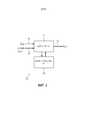
Фиг. 1 показывает устройство кодера в соответствии с примером.FIG. 1 shows an encoder device according to an example.
Фиг. 2 показывает устройство декодера в соответствии с примером.FIG. 2 shows a decoder device according to an example.
Фиг. 3 показывает способ в соответствии с примером.FIG. 3 shows a method according to an example.
Фиг. 3А показывает методики в соответствии с примером.FIG. 3A shows techniques in accordance with an example.
Фиг. 3B и 3C показывают способы в соответствии с примерами.FIG. 3B and 3C show methods in accordance with the examples.
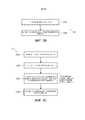
Фиг. 4 показывает способы в соответствии с примерами.FIG. 4 shows methods in accordance with the examples.
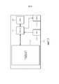
Фиг. 5 показывает устройство кодера в соответствии с примером.FIG. 5 shows an encoder arrangement according to an example.
Фиг. 6 показывает устройство декодера в соответствии с примером.FIG. 6 shows a decoder device according to an example.
Фиг. 7 и 8 показывают устройство кодера в соответствии с примерами.FIG. 7 and 8 show the arrangement of an encoder in accordance with the examples.
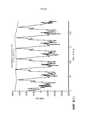
Фиг. 8(1)-8(3) показывают прохождение сигнала в соответствии с примерами.FIG. 8 (1) -8 (3) show the signal flow according to the examples.
5. Примеры5. Examples
Фиг. 1 показывает устройство 10 кодера. Устройство 10 кодера может быть предназначено для обработки (и передачи и/или хранения) информационных сигналов, таких как аудиосигналы. Информационный сигнал может быть разделен на временную последовательность кадров. Каждый кадр может быть представлен, например, в частотной области (FD). Представление FD может являться последовательностью элементов разрешения, каждый из которых находится на конкретной частоте. Представление FD может представлять собой частотный спектр.FIG. 1 shows an
Устройство 10 кодера может, среди прочего, содержать инструмент временного формирования шума (TNS), инструмент 11 предназначен для выполнения фильтрации TNS информационного сигнала 13 в частотной области (FD) (Xs(n)). Устройство 10 кодера может, среди прочего, содержать контроллер 12 TNS. Контроллер 12 TNS может быть выполнен с возможностью управлять инструментом 11 TNS таким образом, чтобы инструмент 11 TNS выполнял фильтрацию (например, для некоторых кадров) с использованием по меньшей мере одной фильтрации с линейным прогнозированием (LP) с более высокой энергией импульсного отклика и (например, для некоторых других кадров) с использованием по меньшей мере одной фильтрации LP с более низкой энергией импульсного отклика. Контроллер 12 TNS выполнен с возможностью выполнять выбор между фильтрацией LP с более высокой энергией импульсного отклика и фильтрацией LP c более низкой энергией импульсного отклика на основе метрики, ассоциированной с кадром (метрики кадра). Энергия импульсного отклика первого фильтра выше, чем энергия импульсного отклика второго фильтра.The
Информационный сигнал 13 FD (Xs(n)) может быть получен, например, от инструмента модифицированного дискретного косинусного преобразования (MDCT) (или модифицированного дискретного синусного преобразования (MDST)), который преобразовал представление кадра из временной области (TD) в частотную область (FD).The
Инструмент 11 TNS может обработать сигналы, например, с использованием группы параметров 14 (a(k)) фильтра c линейным прогнозированием (LP), которые могут являться параметрами первого фильтра 14a. Инструмент 11 TNS может также содержать параметры 14’ (aw(k)), которые могут являться параметрами второго фильтра 15a (второй фильтр 15a может иметь импульсную характеристику с более низкой энергией по сравнению с импульсной характеристикой первого фильтра 14a). Параметры 14’ можно трактовать как взвешенную версию параметров 14, и второй фильтр 15a можно трактовать как произведенный из первого фильтра 14a. Параметры могут содержать, среди прочего, один или более из следующих параметров (или их квантованной версии): коэффициенты кодирования LP (LPC), коэффициенты отражения (RC), коэффициенты rci(k) или их квантованная версия rcq(k), арксинусные коэффициенты отражения (ASRC), логарифмические отношения площадей (LAR), пары спектральных линий (LSP) и/или частоты спектральных линий (LS) или другие виды таких параметров. В примерах возможно использовать любое представление коэффициентов фильтра.The
Выходными данными инструмента 11 TNS может являться отфильтрованная версия 15 (Xf(n)) информационного сигнала 13 FD (Xs(n)).The output of the
Другими выходными данными инструмента 11 TNS может являться группа выходных параметров 16, таких как коэффициенты отражения rci(k) (или их квантованная версия rcq(k)).Other outputs of the
После компонентов 11 и 12 кодер битового потока может закодировать выходные данные 15 и 16 в битовый поток, который может быть передан (например, беспроводным образом с, использованием такого протокола, как Bluetooth) и/или сохранен (например, в блоке хранения большой емкости).After
Фильтрация TNS обеспечивает коэффициенты отражения, которые в общем случае отличаются от нуля. Фильтрация TNS обеспечивает выходные данные, которые в общем случае отличаются от входных данных.TNS filtering provides reflectances that generally differ from zero. TNS filtering provides output that is generally different from the input.
Фиг. 2 показывает устройство 20 декодера, которое может использовать выходные данные (или их обработанную версию) инструмента 11 TNS. Устройство 20 декодера может содержать, среди прочего, декодер 21 TNS и контроллер 22 декодера TNS. Компоненты 21 и 22 могут совместно функционировать, чтобы получить выходные данные 23 синтеза

Как показано на фиг. 1, контроллер 12 TNS может управлять инструментом 11 TNS на основе, среди прочего, метрики 17 кадра (например, коэффициента усиления прогнозирования, или predGain). Например, контроллер 12 TNS может выполнить фильтрацию посредством выбора между по меньшей мере фильтрацией LP с более высокой энергией импульсного отклика и/или фильтрацией LP с более низкой энергией импульсного отклика, и/или между фильтрацией и отсутствием фильтрации. Кроме фильтрации LP с более высокой энергией импульсного отклика и фильтрации LP с более низкой энергией импульсного отклика в соответствии с примеры возможна по меньшей мере одна фильтрация LP с промежуточной энергией импульсного отклика.As shown in FIG. 1, the
Номер для ссылок 17’ на фиг. 1 относится к информации, командам и/или управляющим данным, которые обеспечиваются инструменту 14 TNS от контроллера 12 TNS. Например, инструменту TNS 14 может быть обеспечено решение на основе метрики 17 (например, "использовать первый фильтр" или "использовать второй фильтр"). Настройки фильтров также могут быть обеспечены инструменту 14 TNS. Например, фильтру TNS может быть обеспечен поправочный коэффициент (
Метрика 17, например, может представлять собой метрику, ассоциированную с энергией сигнала в кадре (например, метрика может быть такой, что чем выше энергия, тем выше метрика). Метрика, например, может представлять собой метрику, ассоциированную с ошибкой прогнозирования (например, метрика может быть такой, что чем выше ошибка прогнозирования, тем ниже метрика). Метрика, например, может являться значением, ассоциированным с соотношением между ошибкой прогнозирования и энергией сигнала (например, метрика может быть такой, что чем выше отношение между энергией и ошибкой прогнозирования, тем выше метрика). Метрика, например, может являться коэффициентом усиления прогнозирования для текущего кадра или значением, ассоциированным или пропорциональным коэффициенту усиления прогнозирования для текущего кадра (например, чем выше коэффициент усиления прогнозирования, тем выше метрика). Метрика (17) кадра может быть ассоциирована с пологостью временной огибающей сигнала.
Было отмечено, что артефакты вследствие TNS наступают только тогда (или по меньшей мере преимущественно), когда коэффициент усиления прогнозирования является низким. Таким образом, когда коэффициент усиления прогнозирования является высоким, проблемы, вызванные TNS, не возникают (или имеют меньшую тенденцию к возникновению), и возможно выполнить полное формирование TNS (например, фильтрацию LP с более высокой энергией импульсного отклика). Когда коэффициент усиления прогнозирования является очень низким, предпочтительно совсем не выполнять TNS (отсутствие фильтрации). Когда коэффициент усиления прогнозирования имеет промежуточное значение, предпочтительно сократить эффекты TNS посредством использования фильтрации с линейным прогнозированием с более низкой энергией импульсного отклика (например, посредством взвешивания коэффициентов LP или других параметров фильтрации, и/или коэффициентов отражения, и/или с использованием фильтра, импульсный отклик которого имеет более низкую энергию). Фильтрация LP с более высокой энергией импульсного отклика и фильтрация LP с более низкой энергией импульсного отклика отличаются друг от друга в том, что фильтрация LP с более высокой энергией импульсного отклика определена таким образом, чтобы вызывать более высокую энергию импульсного отклика, чем фильтрация LP с более низкой энергией импульсного отклика. Фильтр в общем случае характеризуется энергией импульсного отклика, и, таким образом, возможно идентифицировать его с помощью его энергии импульсного отклика. Фильтрация LP с более высокой энергией импульсного отклика означает использование фильтра, импульсный отклик которого имеет более высокую энергию, чем у фильтра, используемого при фильтрации LP с более низкой энергией импульсного отклика.It has been observed that artifacts due to TNS only occur (or at least predominantly) when the prediction gain is low. Thus, when the prediction gain is high, problems caused by TNS do not occur (or are less likely to occur), and it is possible to perform complete TNS shaping (eg, LP filtering with a higher impulse response energy). When the prediction gain is very low, it is preferable not to perform TNS at all (no filtering). When the prediction gain is intermediate, it is preferable to reduce TNS effects by using linear prediction filtering with a lower impulse response energy (e.g., by weighting the LP coefficients or other filter parameters and / or reflection coefficients, and / or using a filter, impulse whose response has a lower energy). LP filtering with higher impulse response energy and LP filtering with lower impulse response energy differ from each other in that LP filtering with higher impulse response energy is defined to cause higher impulse response energy than LP filtering with higher impulse response energy. low energy impulse response. A filter is generally characterized by an impulse response energy, and thus it is possible to identify it by its impulse response energy. Filtering LP with a higher impulse response energy means using a filter that has a higher impulse response energy than the filter used in LP filtering with a lower impulse response energy.
Следовательно, с помощью настоящих примеров операции TNS могут быть вычислены посредством:Therefore, with the present examples, TNS operations can be calculated by:
- выполнения фильтрации LP с высокой энергией импульсного отклика, когда метрика (например, коэффициент усиления прогнозирования) является высокой (например, выше порога определения типа фильтрации);- performing LP filtering with high impulse response energy when the metric (eg, prediction gain) is high (eg, above the filter type detection threshold);
- выполнения фильтрации LP с низкой энергией импульсного отклика, когда метрика (например, коэффициент усиления прогнозирования) имеет промежуточное значение (например, между порогом определения фильтрации TNS и порогом определения типа фильтрации); и- performing LP filtering with low impulse response energy when the metric (eg, prediction gain) has an intermediate value (eg, between the TNS filtering detection threshold and the filtering type detection threshold); and
- не выполнения фильтрации TNS, когда метрика (например, коэффициент усиления прогнозирования) является низкой (например, ниже порога определения фильтрации TNS).- not performing TNS filtering when the metric (eg, prediction gain) is low (eg, below the TNS filtering detection threshold).
Фильтрация LP с высокой энергией импульсного отклика может быть получена, например, с использованием первого фильтра, имеющего высокую энергию импульсного отклика. Фильтрация LP с низкой энергией импульсного отклика может быть получена, например, с использованием второго фильтра, имеющего более низкую энергию импульсного отклика. Первый и второй фильтры могут являться линейными независимыми от времени фильтрами (LTI).Filtering LP with a high impulse response energy can be obtained, for example, using a first filter having a high impulse response energy. LP filtering with low impulse response energy can be obtained, for example, using a second filter having a lower impulse response energy. The first and second filters can be linear time-independent (LTI) filters.
В примерах первый фильтр может быть описан с использованием параметров фильтра a(k) (14). В примерах второй фильтр может являться модифицированной версией первого фильтра (например, полученным посредством контроллера 12 TNS). Второй фильтр (фильтр с более низкой энергией импульсного отклика) может быть получен посредством масштабирования с сокращением параметров первого фильтра (например, с использованием параметра


Таким образом, в примерах, когда получены параметры фильтра, и на основе метрики определено, что необходима фильтрация с более низкой энергией импульсного отклика, параметры фильтра первого фильтра могут быть модифицированы (например, масштабированы с сокращением), чтобы получить параметры фильтра второго фильтра для использования для фильтра с более низкой энергией импульсного отклика.Thus, in the examples, when the filter parameters are obtained and based on the metric it is determined that filtering with a lower impulse response energy is needed, the filter parameters of the first filter can be modified (e.g., scaled down) to obtain the filter parameters of the second filter for use. for a filter with a lower impulse response energy.
Фиг. 3 показывает способ 30, который может быть реализован в устройстве 10 кодера.FIG. 3 shows a
На этапе S31 получается метрика кадра (например, коэффициент 17 усиления прогнозирования).In step S31, a frame metric (eg, prediction gain 17) is obtained.
На этапе S32 проверяется, выше ли метрика 17 кадра, чем порог определения фильтрации TNS или первый порог (который может быть равен 1,5 в некоторых примерах). Примером метрики может являться коэффициент усиления прогнозирования.In step S32, it is checked whether the
Если на этапе S32 подтверждено, что метрика 17 кадра ниже, чем первый порог (thresh), на этапе S33 операция фильтрации не выполняется (возможно было бы сказать, что используется фильтр идентичности, который представляет собой фильтр, в котором выходные данные являются такими же, как входные данные). Например, Xf(n)=Xs(n) (выходные данные 15 инструмента 11 TNS совпадают со входными данными 13), и/или коэффициенты отражения rci(k) (и/или их квантованные версии rc0(k)) также устанавливаются равными 0. Таким образом, операции (и выходные данные) устройства 20 декодера не будут подвергаться влиянию инструмента 11 TNS. Следовательно, на этапе S33 не может использоваться ни первый фильтр, ни второй фильтр.If it is confirmed in step S32 that the
Если на этапе S32 подтверждено, что метрика 17 кадра больше, чем порог определения фильтрации TNS или первый порог (thresh), может быть выполнена вторая проверка на этапе S34 посредством сравнения метрики кадра с порогом определения типа фильтрации или вторым порогом (thresh2, который может быть больше, чем первый порог, и равен, например, 2).If it is confirmed in step S32 that the
Если на этапе S34 подтверждено, что метрика 17 кадра ниже, чем порог определения типа фильтрации или второй порог (thresh2), на этапе S35 выполняется фильтрация LP с более низкой энергией импульсного отклика (например, используется второй фильтр с более низкой энергией импульсного отклика, второй фильтр не является фильтром идентичности).If it is confirmed in step S34 that the metric 17 of the frame is lower than the filtering type detection threshold or the second threshold (thresh2), in step S35, LP filtering with a lower impulse response energy is performed (for example, a second filter with a lower impulse response energy is used, the second the filter is not an identity filter).
Если на этапе S34 подтверждено, что метрика 17 кадра больше, чем порог определения типа фильтрации или второй порог (thresh2), на этапе S36 выполняется фильтрация LP с более высокой энергией импульсного отклика (например, используется первый фильтр, энергия импульсного отклика которого выше, чем у фильтра с более низкой энергией).If it is confirmed in step S34 that the
Способ 30 может быть повторен для последующего кадра.
В примерах фильтрация LP с более низкой энергией импульсного отклика (этап S35) может отличаться от фильтрации LP с более высокой энергией импульсного отклика (этап S36) в том, что к параметрам фильтра 14 (a(k)) могут быть применены весовые коэффициенты с разными значениями (например, фильтрация LP с более высокой энергией импульсного отклика может быть основана на единичных весовых коэффициентах, а фильтрация LP с более низкой энергией импульсного отклика может быть основана на весовых коэффициентах ниже единицы). В примерах фильтрация LP с более низкой энергией импульсного отклика может отличаться от фильтрации LP с более высокой энергией импульсного отклика в том, что коэффициенты 16 отражения, полученные посредством выполнения фильтрации LP с более низкой энергией импульсного отклика, могут вызвать более высокое подавление энергии импульсного отклика, чем подавление, вызванное коэффициентами отражения, полученными посредством выполнения фильтрации LP с более высокой энергией импульсного отклика.In the examples, the LP filtering with a lower impulse response energy (step S35) may be different from the LP filtering with a higher impulse response energy (step S36) in that different weights may be applied to the parameters of the filter 14 (a (k)). values (for example, LP filtering with higher impulse response energy may be based on unit weights, and LP filtering with lower impulse response energy may be based on weights below one). In the examples, LP filtering with lower impulse response energy may differ from LP filtering with higher impulse response energy in that
Следовательно, при выполнении фильтрации с более высокой энергией импульсного отклика на этапе S36 первый фильтр используется на основе параметров фильтра 14 (a(k)) (которые являются, таким образом, первыми параметрами фильтра). При выполнении фильтрации с более низкой энергией импульсного отклика на этапе S35 используется второй фильтр. Второй фильтр может быть получен посредством модификации параметров первого фильтра (например, посредством применения весовых коэффициентом меньше единицы).Therefore, when performing filtering with a higher impulse response energy in step S36, the first filter is used based on the filter parameters 14 (a (k)) (which are thus the first filter parameters). When performing filtering with a lower impulse response energy in step S35, a second filter is used. The second filter can be obtained by modifying the parameters of the first filter (eg, by applying weights less than one).
Последовательность этапов S31-S32-S34 может отличаться в других примерах: например, этап S34 может предшествовать этапу S32. Один из этапов S32 и/или S34 может быть необязательным в некоторых примерах.The flow of steps S31-S32-S34 may be different in other examples: for example, step S34 may precede step S32. One of steps S32 and / or S34 may be optional in some examples.
В примерах по меньшей мере один из первого и/или второго порогов может быть фиксирован (например, сохранен в элементе памяти).In the examples, at least one of the first and / or second thresholds may be fixed (eg, stored in a memory element).
В примерах фильтрация с более низкой энергией импульсного отклика может быть получена посредством сокращения импульсного отклика фильтра с помощью регулировки параметров фильтра LP (например, коэффициентов LPC или других параметров фильтрации) и/или коэффициентов отражения, или промежуточного значения, используемого для получения коэффициентов отражения. Например, коэффициенты меньше единицы (весовые коэффициенты) могут быть применены к параметрам фильтра LP (например, коэффициентам LPC или другим параметрам фильтрации) и/или коэффициентам отражения, или промежуточному значению, используемому для получения коэффициентов отражения.In the examples, filtering with a lower impulse response energy can be obtained by reducing the filter impulse response by adjusting LP filter parameters (eg, LPC coefficients or other filter parameters) and / or reflection coefficients, or an intermediate value used to obtain reflection coefficients. For example, coefficients less than one (weights) can be applied to LP filter parameters (eg, LPC coefficients or other filter parameters) and / or reflection coefficients, or an intermediate value used to derive reflection coefficients.
В примерах регулировка (и/или сокращение энергии импульсного отклика) может представлять собой (или выражено как):In the examples, adjusting (and / or reducing the impulse response energy) may be (or expressed as):

где


В одном примере формула может представлять собой:In one example, the formula can be:

где
Из формулы можно заметить, что frameMetrics (или


В примерах фильтрации LP с более низкой энергией импульсного отклика разные значения метрик могут вызвать разные регулировки. Например, более высокий коэффициент усиления прогнозирования может иметь отношение к более высокому значению
Следовательно, последующие кадры того же самого сигнала могут быть отфильтрованы по-другому:Therefore, subsequent frames of the same signal can be filtered differently:
- некоторые кадры могут быть отфильтрованы с использованием первого фильтра (фильтрация с более высокой энергией импульсного отклика), в котором сохраняются параметры (14) фильтра;- some frames can be filtered using the first filter (filtering with a higher impulse response energy), which stores the filter parameters (14);
- некоторые другие кадры могут быть отфильтрованы с использованием второго фильтра (фильтрация с более низкой энергией импульсного отклика), в котором первый фильтр модифицирован, чтобы получить второй фильтр с более низкой энергией импульсного отклика (например, модифицируются параметры 14 фильтра), чтобы сократить энергию импульсного отклика относительно первого фильтра;- some other frames may be filtered using a second filter (filtering with a lower impulse response energy), in which the first filter is modified to obtain a second filter with a lower impulse response energy (for example, filter
- некоторые другие кадры также могут быть отфильтрованы с использованием второго фильтра (фильтрация с более низкой энергией импульсного отклика), но с другой регулировкой (как последовательность разных значений метрики кадра).- some other frames can also be filtered using a second filter (filtering with a lower impulse response energy), but with a different adjustment (as a sequence of different frame metric values).
В соответствии с этим, для каждого кадра может быть определен особый первый фильтр (например, на основе параметров фильтра), в то время как второй фильтр может быть разработан посредством модификации параметров первого фильтра.Accordingly, a specific first filter can be defined for each frame (eg, based on filter parameters), while a second filter can be designed by modifying the parameters of the first filter.
Фиг. 3А показывают пример контроллера 12 и блока 11 TNS, совместно функционирующих для выполнения операций фильтрации TNS.FIG. 3A shows an example of a
Метрика 17 кадра (например, коэффициент усиления прогнозирования) быть получена и сравнена с порогом 18a определения фильтрации TNS (например, в блоке 10a сравнения). Если метрика 17 кадра больше, чем порог 18a определения фильтрации TNS (thresh), разрешается (например, селектором 11a) сравнить метрику 17 кадра с порогом 18b определения типа фильтрации (например, в блоке 12a сравнения). Если метрика кадра 17 больше, чем порог 18b определения типа фильтрации, то активируется первый фильтр 14a, импульсный отклик которого имеет более высокую энергию (например,

Фиг. 3B и 3C показывают способы 36 и 35 для использования первого и второго фильтров 14a и 15a, соответственно (например, для этапов S36 и S35, соответственно).FIG. 3B and 3C show
Способ 36 может содержать этап S36a получения параметров 14 фильтра. Способ 36 может содержать этап S36b выполнения фильтрации (например, этап S36) с использованием параметров первого фильтра 14a. Этап S35b может быть выполнен только при определении (например, на этапе S34), что метрика кадра выше порога определения типа фильтрации (например, на этапе S35).
Способ 35 может содержать этап S35a получения параметров 14 фильтра первого фильтра 14a. Способ 35 может содержать этап S35b определения поправочного коэффициента
Фиг. 4 показывает способ 40’ (на стороне кодера) и способ 40” (на стороне декодера), которые могут сформировать единый способ 40. Способы 40’ и 40” могут иметь некоторый контакт в том, что кодер, работающий в соответствии со способом 40’, может передать битовый поток (например, беспроводным образом с использованием Bluetooth) декодеру, работающему в соответствии со способом 40”.FIG. 4 shows a method 40 '(on the encoder side) and a
Ниже обсуждаются этапы способа 40 (обозначены как последовательность a)-b)-c)-d)-1)-2)-3)-e)-f) и последовательностью S41'-S49’).The steps of method 40 (denoted as sequence a) -b) -c) -d) -1) -2) -3) -e) -f) and sequence S41'-S49 ') are discussed below.
a) Этап S41’: Может быть обработана автокорреляция спектра MDCT (или MDST) (значение FD), например,a) Step S41 ': Spectrum autocorrelation MDCT (or MDST) (FD value) can be processed, for example

где


b) Этап S42’: Автокорреляция может быть обработана с помощью оконной функции задержки:b) Step S42 ': The autocorrelation can be handled with a delay window function:

Пример функции оконной обработки задержки может быть представлен, например:An example of a delay windowing function could be provided, for example:

где

c) Этап S43’: Коэффициенты фильтра LP могут быть оценены с использованием, например, рекурсивной процедуры Левинсона-Дербина, такой как:c) Step S43 ': The LP filter coefficients can be estimated using, for example, the Levinson-Derbin recursive procedure such as:

где


d) Этап S44’: Принятие решения (этап S44’ или S32) включить/выключить фильтрацию TNS текущего кадра может основано, например, на метрике кадра, такой как коэффициент усиления прогнозирования:d) Step S44 ': Deciding (step S44' or S32) to turn on / off TNS filtering of the current frame may be based, for example, on a frame metric such as a prediction gain:
Если
причем коэффициент усиления прогнозирования вычисляется какand the prediction gain is calculated as

и
1) Этап S45’: Весовой коэффициент

где


Когда

2) Этап S46’: Коэффициенты LPC (или другие параметры фильтрации) могут быть взвешены (например, на этапе S46’) с использованием коэффициента


3) Этап S47’: Взвешенные коэффициенты LPC (или другие параметры фильтрации) могут быть преобразованы в коэффициенты отражения, например, с использованием следующей процедуры (этап S47’):3) Step S47 ': The weighted LPC coefficients (or other filter parameters) can be converted to reflection coefficients, for example, using the following procedure (step S47'):

e) Этап S48': Если фильтрация TNS включена (например, в результате определения на этапе S32), коэффициенты отражения могут быть квантованы (этап S48’) с использованием, например, скалярного однородного квантование в области арксинуса:e) Step S48 ': If TNS filtering is on (eg, as a result of determination in step S32), the reflection coefficients can be quantized (step S48') using, for example, scalar uniform quantization in the inverse sine domain:


где


f) Этап S49’:Если фильтрация TNS включена, спектр MDCT (или MDST) фильтруется (этап S49’) с использованием квантованных коэффициентов отражения и структуры решеточного фильтраf) Step S49 ':If TNS filtering is on, the MDCT (or MDST) spectrum is filtered (step S49 ') using the quantized reflectances and grating filter structure

Битовый поток может быть передан декодеру. Битовый поток может содержать вместе с представлением FD информационного сигнала (например, аудиосигнала) также управляющие данные, такие как коэффициенты отражения, полученные посредством выполнения операций TNS, описанных выше (анализ TNS).The bitstream can be transmitted to the decoder. The bitstream may contain, together with the FD representation of an information signal (eg, an audio signal), also control data such as reflection coefficients obtained by performing the TNS operations described above (TNS analysis).
Способ 40” (сторона декодера) может содержать этапы g) (S41”) и h) (S42”), на которых, если фильтрация TNS включена, квантованные коэффициенты отражения декодируются, и квантованный фильтр MDCT (или MDST) подвергается обратной фильтрации. Может использоваться следующая процедура:

На фиг. 5 показан пример устройства 50 кодера (которое может воплотить устройство 10 кодера и/или выполнить по меньшей мере некоторые операции способов 30 и 40’).FIG. 5 shows an example of an encoder device 50 (which may implement an
Устройство 50 кодера может содержать множество инструментов для кодирования входного сигнала (который может являться, например, аудиосигналом). Например, инструмент 51 MDCT может преобразовывать представление TD информационного сигнала в представлении FD. Инструмент 52 формирования спектрального шума (SNS) может выполнять анализ формирования шума (например, анализ формирования спектрального шума (SNS)) и извлекать коэффициенты LPC или другие параметры фильтрации (например, a(k) 14). Инструмент 11 TNS может являться таким, как упомянуто выше, и им может управлять контроллером 12. Инструмент 11 TNS может выполнять операцию фильтрации (например, в соответствии со способом 30 или 40’) и выдавать фильтрованную версию информационного сигнала и версию коэффициентов отражения. Инструмент 13 квантования может выполнять квантование данных, выданных инструментом 11 TNS. Арифметический кодер 54 может обеспечивать, например, энтропийное кодирование. Инструмент 55’ уровня шума также может использоваться для оценки уровня шума сигнала. Блок 55 записи битового потока может формировать битовый поток, ассоциированный с входным сигналом, который может быть передан (например, беспроводным образом с использованием Bluetooth) и/или сохранен.The
Также может использоваться детектор 58’ частотной полосы (который может обнаруживать частотную полосу входного сигнала). Он может обеспечивать информацию об активном спектре сигнала. Эта информация также может использоваться в некоторых примерах, чтобы управлять инструментами кодирования.A frequency band detector 58 '(which can detect the frequency band of the input signal) can also be used. It can provide information about the active spectrum of the signal. This information can also be used in some examples to control coding tools.
Устройство 50 кодера также может содержать инструмент 57 долгосрочной постфильтрации, на вход которого может подаваться представление TD входного сигнала, например, после того как представление TD было дискретизировано с понижением посредством инструмента 56.The
На фиг. 6 показан пример устройства 60 декодера (которое может воплотить устройство 20 декодера и/или выполнить по меньшей мере некоторые операции способа 40”).FIG. 6 shows an example decoder device 60 (which may implement
Устройство 60 декодера может содержать блок 61 считывания, который может считывать битовый поток (например, подготовленный устройством 50). Устройство 60 декодера может содержать арифметический разностный декодер 61a, который может выполнять, например, энтропийное декодирование, разностное декодирование и/или арифметическое декодирование с цифровым представлением в FD (восстановленный спектр), например, как представлено декодером. Устройство 60 декодера может содержать инструмент 62 заполнения шумом и инструмент 63 глобального усиления. Устройство 60 декодера может содержать декодер 21 TNS и контроллер 22 декодера TNS. Устройство 60 может содержать инструмент 65 декодера SNS. Устройство 60 декодера может содержать инструмент 65' обратного преобразования MDCT (или MDST) для преобразования цифрового представления информационного сигнала из области FD в область TD. Долгосрочная постфильтрация может быть выполнена инструментом 66 LTPF 66 в области TD. Информация 68 о частотной полосе может быть получена, например, от детектора 58’ частотной полосы и применена к некоторым инструментам (например, 62 и 21).
Здесь обеспечены примеры операций упомянутого выше устройства.Here, examples of operations of the above device are provided.
Формирование временного шума (TNS) может использоваться инструментом 11 для управления временной формой шума квантования в каждом окне преобразования.Temporal noise shaping (TNS) can be used by the
В примерах, если фильтрация TNS активна в текущем кадре, то могут быть применены до двух фильтров на каждый спектр MDCT (или спектр MDST, или другой спектр или другое представление в области FD). Возможно применить множество фильтров и/или выполнить фильтрацию TNS в конкретном частотном диапазоне. В некоторых примерах это является необязательным.In the examples, if TNS filtering is active in the current frame, then up to two filters can be applied per MDCT spectrum (or MDST spectrum, or another spectrum or other FD domain representation). It is possible to apply multiple filters and / or perform TNS filtering on a specific frequency range. In some examples, this is optional.
Количество фильтров для каждой конфигурации и начальная и конечная частоты каждого фильтра заданы в следующей таблице:The number of filters for each configuration and the start and stop frequencies of each filter are specified in the following table:
{160,213,266}}{{12,61,110},
{160,213,266}}
{213,266,320}}{{61,110,160},
{213,266,320}}
{200,266,333}}{{12,74,137},
{200,266,333}}
{266,333,400}}{{74,137,200},
{266,333,400}}
Такая информация, как начальная и конечная частоты, может быть сообщена, например, детектором 58’ частотной полосы.Information such as start and stop frequencies can be reported, for example, by the frequency band detector 58 '.
Где NB - узкополосный, WB - широкополосный, SSWB - полусуперширокополосный, SWB - суперширокополосный, и FB - полноширокополосный.Where NB is narrowband, WB is broadband, SSWB is semi-super-wideband, SWB is super-wideband, and FB is full-wideband.
Ниже описаны этапы кодирования TNS. Сначала анализ может оценить набор коэффициентов отражения для каждого фильтра TNS. Затем эти коэффициенты отражения могут быть квантованы. И, наконец, спектр преобразования MDCT (или спектр MDST, или другой спектр, или другое представление FD) может быть отфильтрован с использованием квантованных коэффициентов отражения.The steps for coding TNS are described below. The analysis can first estimate a set of reflectances for each TNS filter. Then these reflectances can be quantized. Finally, the MDCT transform spectrum (or the MDST spectrum, or another spectrum, or another FD representation) can be filtered using the quantized reflectances.
Полный анализ TNS, описанный ниже, повторяется для каждого фильтра TNS

Нормализованная автокорреляционная функция может быть вычислена (например, на этапе S41’) следующим образом, для каждого

гдеWhere

иand

где

Нормализованная функция автокорреляции может быть обработана с помощью оконной функции с задержкой (например, на этапе S42’), например, с использованием:The normalized autocorrelation function can be processed with a windowed function with a delay (for example, at step S42 '), for example, using:

Рекурсия Левинсона-Дербина, описанная выше, может использоваться (например, на этапе S43’) для получения коэффициентов LPC или других параметров фильтрации

Решение включить/выключить фильтр TNS
Если
Например, c

Дополнительные описанные ниже этапы выполняются, только если включен фильтр TNS
Весовой коэффициент

где


Коэффициенты LPC или другие параметры фильтрации могут быть взвешены (например, на этапе S46’) с использованием коэффициента


где
Если фильтр TNS
Теперь обсуждается процесс квантования, выполняемый на этапе S48’.The quantization process performed in step S48 'is now discussed.
Для каждого фильтра TNS

иand

где


Порядок квантованных коэффициентов отражения может быть вычислен с использованиемThe order of the quantized reflectances can be calculated using

Общее количество битов, использованных фильтрацией TNS в текущем кадре, может быть вычислено следующим образомThe total number of bits used by TNS filtering in the current frame can be calculated as follows

гдеWhere

иand

Значения

Спектр MDCT (или MDST)

где
Со ссылкой на операции, выполненные в декодере (например, 20, 60), квантованные коэффициенты отражения могут быть получены для каждого фильтра TNS

где
Спектр MDCT (или MDST)

где
6. Обсуждение изобретения6. Discussion of the invention
Как разъяснялось выше, TNS может иногда вносить артефакты, ухудшая качество аудиокодера. Эти артефакты похожи на щелчки или шум и появляются в большинстве случаев с речевыми сигналами или тональными музыкальными сигналами.As explained above, TNS can sometimes introduce artifacts, degrading the quality of the audio encoder. These artifacts are similar to clicks or noise and appear in most cases with speech signals or musical tones.
Было замечено, что артефакты, сформированные TNS, возникают только в кадрах, в которых коэффициент усиления прогнозирования predGain является низким и близок к порогу thresh.It has been observed that artifacts generated by TNS only occur in frames in which the prediction gain of predGain is low and close to the thresh threshold.
Можно было предположить, что увеличение порога легко решит проблему. Но для большинства кадров на самом деле полезно включить фильтрацию TNS, даже когда коэффициент усиления прогнозирования является низким.It could be assumed that increasing the threshold would easily solve the problem. But for most frames, it is actually useful to turn on TNS filtering even when the prediction gain is low.
Наше предлагаемое решение состоит в том, чтобы поддерживать такой же порог, но регулировать фильтр TNS, когда коэффициент усиления прогнозирования является низким, чтобы сократить энергию импульсного отклика.Our proposed solution is to maintain the same threshold but adjust the TNS filter when the prediction gain is low in order to reduce the impulse response energy.
Имеется много способов реализовать эту регулировку (что может называться, как "ослабление", например, когда получается подавление энергии импульсного отклика посредством сокращения параметров фильтра LP). Мы можем использовать весовые коэффициентыThere are many ways to implement this adjustment (which can be referred to as "attenuation", for example, when suppression of the impulse response energy is obtained by reducing the parameters of the LP filter). We can use weights

где

Предлагаемое решение, как доказано, было очень эффективным при удалении всех артефактов на проблематичных кадрах с минимальным воздействием на другие кадры.The proposed solution has been proven to be very effective in removing all artifacts on problematic frames with minimal impact on other frames.
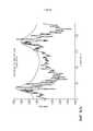
Теперь может быть сделана ссылка на фиг. 8(1)-8(3). Они показывают кадр аудиосигнала (сплошная линия) и частотную характеристику (штриховая линия) соответствующего фильтра прогнозирования TNS.Reference can now be made to FIG. 8 (1) -8 (3). They show the audio frame (solid line) and the frequency response (dashed line) of the corresponding TNS prediction filter.
Фиг. 8(1): сигнал кастаньетFIG. 8 (1): Castanet signal
Фиг. 8(2): сигнал камертонаFIG. 8 (2): tuning fork signal
Фиг. 8(3): речевой сигналFIG. 8 (3): speech signal
Коэффициент усиления прогнозирования относится к пологости временной огибающей сигнала (см., например, раздел 3 [2] или раздел 1.2 [3]).The prediction gain refers to the flatness of the temporal envelope of the signal (see, for example, section 3 [2] or section 1.2 [3]).
Низкий коэффициент усиления прогнозирования подразумевает тенденциозно пологую временную огибающую, в то время как высокий коэффициент усиления прогнозирования подразумевает чрезвычайно не пологую временную огибающую.A low prediction gain implies a biased temporal envelope, while a high prediction gain implies an extremely shallow temporal envelope.
Фиг. 8(1) показывает случай очень низкого коэффициента усиления прогнозирования (predGain=1,0). Это соответствует случаю очень стационарного аудиосигнала с пологой временной огибающей. В этом случае predGain=1 <thresh (например, thresh=1,5): фильтрация не выполняется (этап S33).FIG. 8 (1) shows a case of very low prediction gain (predGain = 1.0). This corresponds to the case of a very stationary audio signal with a shallow temporal envelope. In this case, predGain = 1 <thresh (eg, thresh = 1.5): no filtering is performed (step S33).
Фиг. 8(2) показывает случай очень высокого коэффициента усиления прогнозирования (12,3). Это соответствует случаю сильного и острого нарастания громкости с очень не пологой временной огибающей. В этом случае predGain=12,3 > thresh2 (threh2=2): фильтрация более высокой энергии импульсного отклика выполняется на этапе S36.FIG. 8 (2) shows a case of very high prediction gain (12.3). This corresponds to the case of a strong and sharp increase in loudness with a very flat time envelope. In this case, predGain = 12.3> thresh2 (threh2 = 2): filtering of the higher impulse response energy is performed in step S36.
Фиг. 8(3) показывает случай, когда коэффициент усиления прогнозирования находится между thresh и thresh2, например, в диапазоне 1,5-2,0 (выше, чем первый порог, ниже, чем второй порог). Это соответствует случаю немного не пологой временной огибающей. В этом случае thresh<predGain<thresh2: фильтрация с более низкой энергией импульсного отклика выполнятся на этапе в S35, с использованием второго фильтра 15a с более низкой энергией импульсного отклика.FIG. 8 (3) shows a case where the prediction gain is between thresh and thresh2, for example, in the range of 1.5-2.0 (higher than the first threshold, lower than the second threshold). This corresponds to the case of a slightly sloping temporal envelope. In this case, thresh <predGain <thresh2: filtering with a lower impulse response energy is performed in step in S35 using a
7. Другие примеры7. Other examples
Фиг. 7 показывает устройство 110, которое может реализовать устройство 10 или 50 кодера и/или выполнять по меньшей мере некоторые этапы способа 30 и/или 40’. Устройство 110 может содержать процессор 111 и блок 112 памяти долговременного хранения, хранящий инструкции, которые при их исполнении процессором 111 могут побудить процессор 111 выполнять фильтрацию и/или анализ TNS. Устройство 110 может содержать блок 116 ввода, который может получать входной сигнал (например, аудиосигнал). Процессор 111 может, таким образом, выполнять процессы TNS.FIG. 7 shows a
Фиг. 8 показывает устройство 120, которое может реализовать устройство 20 или 60 декодера и/или выполнить способ 40’. Устройство 120 может содержать процессор 121 и блок 122 памяти долговременного хранения, хранящий инструкции, которые при их исполнении процессором 121 могут побудить процессор 121 выполнять, среди прочего, операцию синтеза TNS. Устройство 120 может содержать блок 126 ввода, который может получать декодированное представление информационного сигнала (например, аудиосигнала) в FD. Процессор 121 может, таким образом, выполнять процессы для получения декодированного представления информационного сигнала, например, в TD. Это декодированное представление может быть предоставлено внешним блокам с использованием блока 127 вывода. Блок 127 вывода может содержать, например, блок связи для взаимодействия с внешним устройствами (например, с использованием беспроводной связи, такой как Bluetooth) и/или внешними пространствами памяти. Процессор 121 может хранить декодированное представление аудиосигнала в локальном пространстве 128 памяти.FIG. 8 shows an apparatus 120 that can implement
В примерах системы 110 и 120 могут быть одним и тем же устройством.In the examples,
В зависимости от некоторых требований реализации примеры могут быть реализованы в аппаратных средствах. Реализация может быть выполнена с использованием цифровых носителей информации, например, гибкого диска, цифрового универсального диска (DVD), диска Blu-ray, компакт-диска (CD), постоянного запоминающего устройства (ПЗУ; ROM), программируемого ПЗУ (ППЗУ; PROM), стираемого и программируемого ПЗУ (ЭПЗЗУ; EPROM), электрически стираемого ЭППЗУ (ЭСППЗУ EEPROM) или флэш-памяти, хранящих считываемые в электронном виде сигналы, которые могут выполнять соответствующий способ. Таким образом, цифровой носитель информации может быть машиночитаемым.Depending on some implementation requirements, the examples can be implemented in hardware. Implementation can be performed using digital storage media such as floppy disk, digital versatile disk (DVD), Blu-ray disk, compact disk (CD), read only memory (ROM; ROM), programmable ROM (EPROM; PROM) , erasable and programmable ROM (EPROM; EPROM), electrically erasable EEPROM (EEPROM) or flash memory, storing electronically readable signals that can perform the corresponding method. Thus, a digital storage medium can be machine-readable.
Обычно примеры могут быть реализованы как компьютерный программный продукт с программными командами, программные команды выполняют один из способов, когда компьютерный программный продукт исполняется на компьютере. Программные команды могут быть сохранены на машиночитаемом носителе.Typically, the examples can be implemented as a computer program product with program instructions, the program instructions execute in one of the ways when the computer program product is executed on a computer. Programming instructions can be stored on a computer-readable medium.
Другие примеры содержат компьютерную программу для выполнения одного из способов, описанных в настоящем документе, сохраненных на машиночитаемой носителе. Другими словами, примером способа, таким образом, является компьютерная программа, имеющая программные команды для выполнения одного из способов, описанных в настоящем документе, когда компьютерная программа выполняется на компьютере.Other examples comprise a computer program for performing one of the methods described herein stored on a computer-readable medium. In other words, an example of a method is thus a computer program having program instructions for executing one of the methods described herein when the computer program is executed on a computer.
Дополнительным примером способов, таким образом, является носитель данных (или цифровой носитель информации, или машиночитаемый носитель) содержащий записанную на нем компьютерную программу для выполнения одного из способов, описанных в настоящем документе. Носитель данных, цифровой носитель информации или носитель с записанными данными являются материальными и/или не временным носителем, а не нематериальными и временными сигналами.An additional example of methods, therefore, is a storage medium (or digital storage medium or computer-readable medium) containing a computer program recorded thereon for performing one of the methods described herein. A storage medium, digital storage medium, or recorded data medium are tangible and / or non-temporary media, not intangible and temporary signals.
Дополнительный пример содержит блок обработки, например, компьютер или программируемое логическое устройство, выполняющее один из способов, описанных в настоящем документе.An additional example comprises a processing unit, such as a computer or programmable logic device, performing one of the methods described herein.
Дополнительный пример содержит компьютер с установленной на нем компьютерной программой для выполнения одного из способов, описанных в настоящем документе.An additional example contains a computer with a computer program installed on it to perform one of the methods described in this document.
Дополнительный пример содержит устройство или систему, переносящую (например, в электронном виде или оптически) компьютерную программу для выполнения одного из способов, описанных в настоящем документе, к приемнику. Приемник может, например, являться компьютером, мобильным устройством, запоминающим устройством и т.п. Устройство или система могут, например, содержать файловый сервер для переноса компьютерной программы к приемнику.An additional example comprises a device or system that transfers (eg, electronically or optically) a computer program for performing one of the methods described herein to a receiver. The receiver may, for example, be a computer, mobile device, storage device, or the like. The device or system may, for example, comprise a file server for transferring a computer program to a receiver.
В некоторых примерах программируемое логическое устройство (например, программируемая пользователем вентильная матрица) может использоваться, чтобы выполнять некоторые или все функции способов, описанных в настоящем документе. В некоторых примерах программируемая пользователем вентильная матрица может взаимодействовать с микропроцессором, чтобы выполнять один из способов, описанных в настоящем документе. Обычно способы могут быть выполнены любым подходящим аппаратным устройством.In some examples, a programmable logic device (eg, a field programmable gate array) may be used to perform some or all of the functions of the methods described herein. In some examples, the field programmable gate array may interact with a microprocessor to perform one of the techniques described herein. Typically, the methods can be performed by any suitable hardware device.
Описанные выше примеры являются иллюстративным для обсуждаемых выше принципов. Подразумевается, что модификации и вариации подробностей, описанных в настоящем документе, будут очевидны. Таким образом, объем описания ограничен лишь формулой изобретения, а не подробностями, представленными в примерах настоящего документа.The examples described above are illustrative of the principles discussed above. It is understood that modifications and variations of the details described herein will be apparent. Thus, the scope of the description is limited only by the claims, and not by the details presented in the examples of this document.
Claims (49)
Translated fromRussian


Applications Claiming Priority (3)
| Application Number | Priority Date | Filing Date | Title |
|---|---|---|---|
| EP17201094.4AEP3483880A1 (en) | 2017-11-10 | 2017-11-10 | Temporal noise shaping |
| EP17201094.4 | 2017-11-10 | ||
| PCT/EP2018/080339WO2019091978A1 (en) | 2017-11-10 | 2018-11-06 | Temporal noise shaping |
Publications (1)
| Publication Number | Publication Date |
|---|---|
| RU2740074C1true RU2740074C1 (en) | 2021-01-11 |
Family
ID=60301908
Family Applications (1)
| Application Number | Title | Priority Date | Filing Date |
|---|---|---|---|
| RU2020118948ARU2740074C1 (en) | 2017-11-10 | 2018-11-06 | Temporal formation of noise |
Country Status (19)
| Country | Link |
|---|---|
| US (1) | US11127408B2 (en) |
| EP (2) | EP3483880A1 (en) |
| JP (1) | JP6990306B2 (en) |
| KR (1) | KR102428419B1 (en) |
| CN (1) | CN111587456B (en) |
| AR (1) | AR113480A1 (en) |
| AU (1) | AU2018363699B2 (en) |
| BR (1) | BR112020009104A2 (en) |
| CA (1) | CA3081781C (en) |
| ES (1) | ES2905911T3 (en) |
| MX (1) | MX2020004789A (en) |
| MY (1) | MY206211A (en) |
| PL (1) | PL3707712T3 (en) |
| PT (1) | PT3707712T (en) |
| RU (1) | RU2740074C1 (en) |
| SG (1) | SG11202004204UA (en) |
| TW (1) | TWI701658B (en) |
| WO (1) | WO2019091978A1 (en) |
| ZA (1) | ZA202002520B (en) |
Families Citing this family (3)
| Publication number | Priority date | Publication date | Assignee | Title |
|---|---|---|---|---|
| JP6642146B2 (en) | 2015-03-31 | 2020-02-05 | 日立金属株式会社 | Silicon nitride based ceramic aggregate substrate and method of manufacturing the same |
| CN113643713B (en)* | 2021-10-13 | 2021-12-24 | 北京百瑞互联技术有限公司 | Bluetooth audio coding method, device and storage medium |
| CN114613375A (en)* | 2022-02-28 | 2022-06-10 | 恒玄科技(上海)股份有限公司 | Time domain noise shaping method and device for audio signal |
Citations (5)
| Publication number | Priority date | Publication date | Assignee | Title |
|---|---|---|---|---|
| EP0797324B1 (en)* | 1996-03-22 | 2004-11-24 | Lucent Technologies Inc. | Enhanced joint stereo coding method using temporal envelope shaping |
| EP0785631B1 (en)* | 1996-01-16 | 2007-03-21 | Lucent Technologies Inc. | Perceptual noise shaping in the time domain via LPC prediction in the frequency domain |
| US20110019829A1 (en)* | 2008-04-04 | 2011-01-27 | Panasonic Corporation | Stereo signal converter, stereo signal reverse converter, and methods for both |
| RU2591661C2 (en)* | 2009-10-08 | 2016-07-20 | Фраунхофер-Гезелльшафт цур Фёрдерунг дер ангевандтен Форшунг Е.Ф. | Multimode audio signal decoder, multimode audio signal encoder, methods and computer programs using linear predictive coding based on noise limitation |
| CN104269173B (en)* | 2014-09-30 | 2018-03-13 | 武汉大学深圳研究院 | The audio bandwidth expansion apparatus and method of switch mode |
Family Cites Families (146)
| Publication number | Priority date | Publication date | Assignee | Title |
|---|---|---|---|---|
| DE3639753A1 (en) | 1986-11-21 | 1988-06-01 | Inst Rundfunktechnik Gmbh | METHOD FOR TRANSMITTING DIGITALIZED SOUND SIGNALS |
| US5012517A (en) | 1989-04-18 | 1991-04-30 | Pacific Communication Science, Inc. | Adaptive transform coder having long term predictor |
| US5233660A (en) | 1991-09-10 | 1993-08-03 | At&T Bell Laboratories | Method and apparatus for low-delay celp speech coding and decoding |
| JPH05281996A (en) | 1992-03-31 | 1993-10-29 | Sony Corp | Pitch extracting device |
| IT1270438B (en) | 1993-06-10 | 1997-05-05 | Sip | PROCEDURE AND DEVICE FOR THE DETERMINATION OF THE FUNDAMENTAL TONE PERIOD AND THE CLASSIFICATION OF THE VOICE SIGNAL IN NUMERICAL CODERS OF THE VOICE |
| US5581653A (en) | 1993-08-31 | 1996-12-03 | Dolby Laboratories Licensing Corporation | Low bit-rate high-resolution spectral envelope coding for audio encoder and decoder |
| JP3402748B2 (en) | 1994-05-23 | 2003-05-06 | 三洋電機株式会社 | Pitch period extraction device for audio signal |
| EP0732687B2 (en) | 1995-03-13 | 2005-10-12 | Matsushita Electric Industrial Co., Ltd. | Apparatus for expanding speech bandwidth |
| WO1997027578A1 (en) | 1996-01-26 | 1997-07-31 | Motorola Inc. | Very low bit rate time domain speech analyzer for voice messaging |
| JPH1091194A (en) | 1996-09-18 | 1998-04-10 | Sony Corp | Method of voice decoding and device therefor |
| US6570991B1 (en) | 1996-12-18 | 2003-05-27 | Interval Research Corporation | Multi-feature speech/music discrimination system |
| KR100261253B1 (en) | 1997-04-02 | 2000-07-01 | 윤종용 | Scalable audio encoder/decoder and audio encoding/decoding method |
| GB2326572A (en) | 1997-06-19 | 1998-12-23 | Softsound Limited | Low bit rate audio coder and decoder |
| WO1999016050A1 (en) | 1997-09-23 | 1999-04-01 | Voxware, Inc. | Scalable and embedded codec for speech and audio signals |
| US6507814B1 (en) | 1998-08-24 | 2003-01-14 | Conexant Systems, Inc. | Pitch determination using speech classification and prior pitch estimation |
| US7272556B1 (en) | 1998-09-23 | 2007-09-18 | Lucent Technologies Inc. | Scalable and embedded codec for speech and audio signals |
| US6735561B1 (en)* | 2000-03-29 | 2004-05-11 | At&T Corp. | Effective deployment of temporal noise shaping (TNS) filters |
| US7099830B1 (en)* | 2000-03-29 | 2006-08-29 | At&T Corp. | Effective deployment of temporal noise shaping (TNS) filters |
| US7395209B1 (en) | 2000-05-12 | 2008-07-01 | Cirrus Logic, Inc. | Fixed point audio decoding system and method |
| US7020605B2 (en)* | 2000-09-15 | 2006-03-28 | Mindspeed Technologies, Inc. | Speech coding system with time-domain noise attenuation |
| US7512535B2 (en) | 2001-10-03 | 2009-03-31 | Broadcom Corporation | Adaptive postfiltering methods and systems for decoding speech |
| US6785645B2 (en) | 2001-11-29 | 2004-08-31 | Microsoft Corporation | Real-time speech and music classifier |
| US20030187663A1 (en)* | 2002-03-28 | 2003-10-02 | Truman Michael Mead | Broadband frequency translation for high frequency regeneration |
| US7447631B2 (en) | 2002-06-17 | 2008-11-04 | Dolby Laboratories Licensing Corporation | Audio coding system using spectral hole filling |
| US7502743B2 (en) | 2002-09-04 | 2009-03-10 | Microsoft Corporation | Multi-channel audio encoding and decoding with multi-channel transform selection |
| US7433824B2 (en) | 2002-09-04 | 2008-10-07 | Microsoft Corporation | Entropy coding by adapting coding between level and run-length/level modes |
| JP4287637B2 (en) | 2002-10-17 | 2009-07-01 | パナソニック株式会社 | Speech coding apparatus, speech coding method, and program |
| ATE339759T1 (en) | 2003-02-11 | 2006-10-15 | Koninkl Philips Electronics Nv | AUDIO CODING |
| KR20030031936A (en) | 2003-02-13 | 2003-04-23 | 배명진 | Mutiple Speech Synthesizer using Pitch Alteration Method |
| CN1809873B (en) | 2003-06-17 | 2010-05-12 | 松下电器产业株式会社 | Receiver, sender and transmission system |
| EP1642265B1 (en)* | 2003-06-30 | 2010-10-27 | Koninklijke Philips Electronics N.V. | Improving quality of decoded audio by adding noise |
| WO2005027096A1 (en) | 2003-09-15 | 2005-03-24 | Zakrytoe Aktsionernoe Obschestvo Intel | Method and apparatus for encoding audio |
| US7009533B1 (en) | 2004-02-13 | 2006-03-07 | Samplify Systems Llc | Adaptive compression and decompression of bandlimited signals |
| DE102004009949B4 (en) | 2004-03-01 | 2006-03-09 | Fraunhofer-Gesellschaft zur Förderung der angewandten Forschung e.V. | Device and method for determining an estimated value |
| EP1721312B1 (en) | 2004-03-01 | 2008-03-26 | Dolby Laboratories Licensing Corporation | Multichannel audio coding |
| DE102004009954B4 (en)* | 2004-03-01 | 2005-12-15 | Fraunhofer-Gesellschaft zur Förderung der angewandten Forschung e.V. | Apparatus and method for processing a multi-channel signal |
| CN1930607B (en) | 2004-03-05 | 2010-11-10 | 松下电器产业株式会社 | Error conceal device and error conceal method |
| CA2602804C (en) | 2005-04-01 | 2013-12-24 | Qualcomm Incorporated | Systems, methods, and apparatus for highband burst suppression |
| US7546240B2 (en) | 2005-07-15 | 2009-06-09 | Microsoft Corporation | Coding with improved time resolution for selected segments via adaptive block transformation of a group of samples from a subband decomposition |
| US7539612B2 (en) | 2005-07-15 | 2009-05-26 | Microsoft Corporation | Coding and decoding scale factor information |
| KR100888474B1 (en) | 2005-11-21 | 2009-03-12 | 삼성전자주식회사 | Apparatus and method for encoding/decoding multichannel audio signal |
| US7805297B2 (en) | 2005-11-23 | 2010-09-28 | Broadcom Corporation | Classification-based frame loss concealment for audio signals |
| WO2007070007A1 (en) | 2005-12-14 | 2007-06-21 | Matsushita Electric Industrial Co., Ltd. | A method and system for extracting audio features from an encoded bitstream for audio classification |
| US8255207B2 (en) | 2005-12-28 | 2012-08-28 | Voiceage Corporation | Method and device for efficient frame erasure concealment in speech codecs |
| CN101395661B (en) | 2006-03-07 | 2013-02-06 | 艾利森电话股份有限公司 | Method and device for audio encoding and decoding |
| US8150065B2 (en) | 2006-05-25 | 2012-04-03 | Audience, Inc. | System and method for processing an audio signal |
| WO2007138511A1 (en) | 2006-05-30 | 2007-12-06 | Koninklijke Philips Electronics N.V. | Linear predictive coding of an audio signal |
| US8015000B2 (en) | 2006-08-03 | 2011-09-06 | Broadcom Corporation | Classification-based frame loss concealment for audio signals |
| JP5096468B2 (en)* | 2006-08-15 | 2012-12-12 | ドルビー ラボラトリーズ ライセンシング コーポレイション | Free shaping of temporal noise envelope without side information |
| FR2905510B1 (en) | 2006-09-01 | 2009-04-10 | Voxler Soc Par Actions Simplif | REAL-TIME VOICE ANALYSIS METHOD FOR REAL-TIME CONTROL OF A DIGITAL MEMBER AND ASSOCIATED DEVICE |
| CN101140759B (en) | 2006-09-08 | 2010-05-12 | 华为技术有限公司 | Bandwidth extension method and system for voice or audio signal |
| DE102006049154B4 (en) | 2006-10-18 | 2009-07-09 | Fraunhofer-Gesellschaft zur Förderung der angewandten Forschung e.V. | Coding of an information signal |
| KR101292771B1 (en) | 2006-11-24 | 2013-08-16 | 삼성전자주식회사 | Method and Apparatus for error concealment of Audio signal |
| CN101548319B (en) | 2006-12-13 | 2012-06-20 | 松下电器产业株式会社 | Post filter and filtering method |
| FR2912249A1 (en) | 2007-02-02 | 2008-08-08 | France Telecom | Time domain aliasing cancellation type transform coding method for e.g. audio signal of speech, involves determining frequency masking threshold to apply to sub band, and normalizing threshold to permit spectral continuity between sub bands |
| JP4871894B2 (en) | 2007-03-02 | 2012-02-08 | パナソニック株式会社 | Encoding device, decoding device, encoding method, and decoding method |
| JP5618826B2 (en) | 2007-06-14 | 2014-11-05 | ヴォイスエイジ・コーポレーション | ITU. T Recommendation G. Apparatus and method for compensating for frame loss in PCM codec interoperable with 711 |
| EP2015293A1 (en) | 2007-06-14 | 2009-01-14 | Deutsche Thomson OHG | Method and apparatus for encoding and decoding an audio signal using adaptively switched temporal resolution in the spectral domain |
| JP4928366B2 (en) | 2007-06-25 | 2012-05-09 | 日本電信電話株式会社 | Pitch search device, packet loss compensation device, method thereof, program, and recording medium thereof |
| JP4572218B2 (en) | 2007-06-27 | 2010-11-04 | 日本電信電話株式会社 | Music segment detection method, music segment detection device, music segment detection program, and recording medium |
| WO2009027606A1 (en) | 2007-08-24 | 2009-03-05 | France Telecom | Encoding/decoding by symbol planes with dynamic calculation of probability tables |
| ES2375192T3 (en) | 2007-08-27 | 2012-02-27 | Telefonaktiebolaget L M Ericsson (Publ) | CODIFICATION FOR IMPROVED SPEECH TRANSFORMATION AND AUDIO SIGNALS. |
| CN100524462C (en) | 2007-09-15 | 2009-08-05 | 华为技术有限公司 | Method and apparatus for concealing frame error of high belt signal |
| BRPI0818927A2 (en) | 2007-11-02 | 2015-06-16 | Huawei Tech Co Ltd | Method and apparatus for audio decoding |
| WO2009066869A1 (en)* | 2007-11-21 | 2009-05-28 | Electronics And Telecommunications Research Institute | Frequency band determining method for quantization noise shaping and transient noise shaping method using the same |
| AU2008344134B2 (en) | 2007-12-31 | 2011-08-25 | Lg Electronics Inc. | A method and an apparatus for processing an audio signal |
| BRPI0915358B1 (en) | 2008-06-13 | 2020-04-22 | Nokia Corp | method and apparatus for hiding frame error in encoded audio data using extension encoding |
| PL2346030T3 (en) | 2008-07-11 | 2015-03-31 | Fraunhofer Ges Forschung | Audio encoder, method for encoding an audio signal and computer program |
| EP2144231A1 (en) | 2008-07-11 | 2010-01-13 | Fraunhofer-Gesellschaft zur Förderung der angewandten Forschung e.V. | Low bitrate audio encoding/decoding scheme with common preprocessing |
| EP2144230A1 (en) | 2008-07-11 | 2010-01-13 | Fraunhofer-Gesellschaft zur Förderung der angewandten Forschung e.V. | Low bitrate audio encoding/decoding scheme having cascaded switches |
| AU2009267394B2 (en) | 2008-07-11 | 2012-10-18 | Fraunhofer-Gesellschaft Zur Foerderung Der Angewandten Forschung E.V. | Audio encoder and decoder for encoding frames of sampled audio signals |
| US8577673B2 (en) | 2008-09-15 | 2013-11-05 | Huawei Technologies Co., Ltd. | CELP post-processing for music signals |
| TWI419148B (en) | 2008-10-08 | 2013-12-11 | Fraunhofer Ges Forschung | Multi-resolution switched audio encoding/decoding scheme |
| GB2466673B (en) | 2009-01-06 | 2012-11-07 | Skype | Quantization |
| ES2567129T3 (en) | 2009-01-28 | 2016-04-20 | Fraunhofer-Gesellschaft zur Förderung der angewandten Forschung e.V. | Audio encoder, audio decoder, encoded audio information, methods for encoding and decoding an audio signal and computer program |
| JP4945586B2 (en) | 2009-02-02 | 2012-06-06 | 株式会社東芝 | Signal band expander |
| JP4932917B2 (en) | 2009-04-03 | 2012-05-16 | 株式会社エヌ・ティ・ティ・ドコモ | Speech decoding apparatus, speech decoding method, and speech decoding program |
| FR2944664A1 (en) | 2009-04-21 | 2010-10-22 | Thomson Licensing | Image i.e. source image, processing device, has interpolators interpolating compensated images, multiplexer alternately selecting output frames of interpolators, and display unit displaying output images of multiplexer |
| US8428938B2 (en) | 2009-06-04 | 2013-04-23 | Qualcomm Incorporated | Systems and methods for reconstructing an erased speech frame |
| US8352252B2 (en) | 2009-06-04 | 2013-01-08 | Qualcomm Incorporated | Systems and methods for preventing the loss of information within a speech frame |
| KR20100136890A (en) | 2009-06-19 | 2010-12-29 | 삼성전자주식회사 | Context-based Arithmetic Coding Apparatus and Method and Arithmetic Decoding Apparatus and Method |
| CN101958119B (en) | 2009-07-16 | 2012-02-29 | 中兴通讯股份有限公司 | Audio-frequency drop-frame compensator and compensation method for modified discrete cosine transform domain |
| ES2888804T3 (en)* | 2009-10-15 | 2022-01-07 | Voiceage Corp | Simultaneous noise shaping in the time domain and the frequency domain for TDAC transformations |
| WO2011048118A1 (en) | 2009-10-20 | 2011-04-28 | Fraunhofer Gesellschaft zur Förderung der angewandten Forschung e.V. | Audio signal encoder, audio signal decoder, method for providing an encoded representation of an audio content, method for providing a decoded representation of an audio content and computer program for use in low delay applications |
| MY160807A (en) | 2009-10-20 | 2017-03-31 | Fraunhofer-Gesellschaft Zur Förderung Der Angewandten | Audio encoder,audio decoder,method for encoding an audio information,method for decoding an audio information and computer program using a detection of a group of previously-decoded spectral values |
| US8207875B2 (en) | 2009-10-28 | 2012-06-26 | Motorola Mobility, Inc. | Encoder that optimizes bit allocation for information sub-parts |
| US7978101B2 (en) | 2009-10-28 | 2011-07-12 | Motorola Mobility, Inc. | Encoder and decoder using arithmetic stage to compress code space that is not fully utilized |
| KR101761629B1 (en) | 2009-11-24 | 2017-07-26 | 엘지전자 주식회사 | Audio signal processing method and device |
| CN102844809B (en) | 2010-01-12 | 2015-02-18 | 弗劳恩霍弗实用研究促进协会 | Audio encoder, audio decoder, method for encoding and audio information, method for decoding an audio information and computer program using a hash table describing both significant state values and interval boundaries |
| US20110196673A1 (en) | 2010-02-11 | 2011-08-11 | Qualcomm Incorporated | Concealing lost packets in a sub-band coding decoder |
| EP2375409A1 (en) | 2010-04-09 | 2011-10-12 | Fraunhofer-Gesellschaft zur Förderung der angewandten Forschung e.V. | Audio encoder, audio decoder and related methods for processing multi-channel audio signals using complex prediction |
| FR2961980A1 (en)* | 2010-06-24 | 2011-12-30 | France Telecom | CONTROLLING A NOISE SHAPING FEEDBACK IN AUDIONUMERIC SIGNAL ENCODER |
| ES2683648T3 (en) | 2010-07-02 | 2018-09-27 | Dolby International Ab | Audio decoding with selective post-filtering |
| JP5600805B2 (en) | 2010-07-20 | 2014-10-01 | フラウンホッファー−ゲゼルシャフト ツァ フェルダールング デァ アンゲヴァンテン フォアシュンク エー.ファオ | Audio encoder using optimized hash table, audio decoder, method for encoding audio information, method for decoding audio information, and computer program |
| US8738385B2 (en) | 2010-10-20 | 2014-05-27 | Broadcom Corporation | Pitch-based pre-filtering and post-filtering for compression of audio signals |
| SG192748A1 (en) | 2011-02-14 | 2013-09-30 | Fraunhofer Ges Forschung | Linear prediction based coding scheme using spectral domain noise shaping |
| US9270807B2 (en) | 2011-02-23 | 2016-02-23 | Digimarc Corporation | Audio localization using audio signal encoding and recognition |
| JP5820487B2 (en) | 2011-03-18 | 2015-11-24 | フラウンホーファーゲゼルシャフトツール フォルデルング デル アンゲヴァンテン フォルシユング エー.フアー. | Frame element positioning in a bitstream frame representing audio content |
| US8977543B2 (en) | 2011-04-21 | 2015-03-10 | Samsung Electronics Co., Ltd. | Apparatus for quantizing linear predictive coding coefficients, sound encoding apparatus, apparatus for de-quantizing linear predictive coding coefficients, sound decoding apparatus, and electronic device therefore |
| US8891775B2 (en)* | 2011-05-09 | 2014-11-18 | Dolby International Ab | Method and encoder for processing a digital stereo audio signal |
| FR2977439A1 (en) | 2011-06-28 | 2013-01-04 | France Telecom | WINDOW WINDOWS IN ENCODING / DECODING BY TRANSFORMATION WITH RECOVERY, OPTIMIZED IN DELAY. |
| FR2977969A1 (en) | 2011-07-12 | 2013-01-18 | France Telecom | ADAPTATION OF ANALYSIS OR SYNTHESIS WEIGHTING WINDOWS FOR TRANSFORMED CODING OR DECODING |
| KR20140085453A (en)* | 2011-10-27 | 2014-07-07 | 엘지전자 주식회사 | Method for encoding voice signal, method for decoding voice signal, and apparatus using same |
| MX350686B (en) | 2012-01-20 | 2017-09-13 | Fraunhofer Ges Forschung | Apparatus and method for audio encoding and decoding employing sinusoidal substitution. |
| KR101621287B1 (en) | 2012-04-05 | 2016-05-16 | 후아웨이 테크놀러지 컴퍼니 리미티드 | Method for determining an encoding parameter for a multi-channel audio signal and multi-channel audio encoder |
| US20130282372A1 (en) | 2012-04-23 | 2013-10-24 | Qualcomm Incorporated | Systems and methods for audio signal processing |
| TWI585748B (en) | 2012-06-08 | 2017-06-01 | 三星電子股份有限公司 | Frame error concealment method and audio decoding method |
| GB201210373D0 (en) | 2012-06-12 | 2012-07-25 | Meridian Audio Ltd | Doubly compatible lossless audio sandwidth extension |
| FR2992766A1 (en)* | 2012-06-29 | 2014-01-03 | France Telecom | EFFECTIVE MITIGATION OF PRE-ECHO IN AUDIONUMERIC SIGNAL |
| CN102779526B (en) | 2012-08-07 | 2014-04-16 | 无锡成电科大科技发展有限公司 | Pitch extraction and correcting method in speech signal |
| US9406307B2 (en) | 2012-08-19 | 2016-08-02 | The Regents Of The University Of California | Method and apparatus for polyphonic audio signal prediction in coding and networking systems |
| US9293146B2 (en) | 2012-09-04 | 2016-03-22 | Apple Inc. | Intensity stereo coding in advanced audio coding |
| TWI553628B (en) | 2012-09-24 | 2016-10-11 | 三星電子股份有限公司 | Frame error concealment method |
| US9401153B2 (en) | 2012-10-15 | 2016-07-26 | Digimarc Corporation | Multi-mode audio recognition and auxiliary data encoding and decoding |
| KR101897092B1 (en)* | 2013-01-29 | 2018-09-11 | 프라운호퍼 게젤샤프트 쭈르 푀르데룽 데어 안겐반텐 포르슝 에.베. | Noise Filling Concept |
| FR3001593A1 (en) | 2013-01-31 | 2014-08-01 | France Telecom | IMPROVED FRAME LOSS CORRECTION AT SIGNAL DECODING. |
| MX344550B (en) | 2013-02-05 | 2016-12-20 | Ericsson Telefon Ab L M | Method and apparatus for controlling audio frame loss concealment. |
| TWI530941B (en) | 2013-04-03 | 2016-04-21 | 杜比實驗室特許公司 | Method and system for interactive imaging based on object audio |
| MY181845A (en) | 2013-06-21 | 2021-01-08 | Fraunhofer Ges Forschung | Apparatus and method for improved concealment of the adaptive codebook in acelp-like concealment employing improved pulse resynchronization |
| EP2830059A1 (en)* | 2013-07-22 | 2015-01-28 | Fraunhofer-Gesellschaft zur Förderung der angewandten Forschung e.V. | Noise filling energy adjustment |
| EP2830055A1 (en) | 2013-07-22 | 2015-01-28 | Fraunhofer-Gesellschaft zur Förderung der angewandten Forschung e.V. | Context-based entropy coding of sample values of a spectral envelope |
| PL3058566T3 (en) | 2013-10-18 | 2018-07-31 | Fraunhofer-Gesellschaft zur Förderung der angewandten Forschung e.V. | Coding of spectral coefficients of a spectrum of an audio signal |
| US9906858B2 (en) | 2013-10-22 | 2018-02-27 | Bongiovi Acoustics Llc | System and method for digital signal processing |
| TR201802303T4 (en) | 2013-10-31 | 2018-03-21 | Fraunhofer Ges Forschung | Audio bandwidth extension with the addition of temporal preformed noise in the frequency domain. |
| SG10201709061WA (en) | 2013-10-31 | 2017-12-28 | Fraunhofer Ges Forschung | Audio decoder and method for providing a decoded audio information using an error concealment modifying a time domain excitation signal |
| AU2014350366B2 (en) | 2013-11-13 | 2017-02-23 | Fraunhofer-Gesellschaft Zur Foerderung Der Angewandten Forschung E.V. | Encoder for encoding an audio signal, audio transmission system and method for determining correction values |
| GB2524333A (en) | 2014-03-21 | 2015-09-23 | Nokia Technologies Oy | Audio signal payload |
| US9396733B2 (en) | 2014-05-06 | 2016-07-19 | University Of Macau | Reversible audio data hiding |
| NO2780522T3 (en) | 2014-05-15 | 2018-06-09 | ||
| EP2963646A1 (en) | 2014-07-01 | 2016-01-06 | Fraunhofer-Gesellschaft zur Förderung der angewandten Forschung e.V. | Decoder and method for decoding an audio signal, encoder and method for encoding an audio signal |
| US9685166B2 (en) | 2014-07-26 | 2017-06-20 | Huawei Technologies Co., Ltd. | Classification between time-domain coding and frequency domain coding |
| EP2980798A1 (en) | 2014-07-28 | 2016-02-03 | Fraunhofer-Gesellschaft zur Förderung der angewandten Forschung e.V. | Harmonicity-dependent controlling of a harmonic filter tool |
| EP2980799A1 (en) | 2014-07-28 | 2016-02-03 | Fraunhofer-Gesellschaft zur Förderung der angewandten Forschung e.V. | Apparatus and method for processing an audio signal using a harmonic post-filter |
| EP2980796A1 (en) | 2014-07-28 | 2016-02-03 | Fraunhofer-Gesellschaft zur Förderung der angewandten Forschung e.V. | Method and apparatus for processing an audio signal, audio decoder, and audio encoder |
| EP2988300A1 (en) | 2014-08-18 | 2016-02-24 | Fraunhofer-Gesellschaft zur Förderung der angewandten Forschung e.V. | Switching of sampling rates at audio processing devices |
| EP3067886A1 (en) | 2015-03-09 | 2016-09-14 | Fraunhofer-Gesellschaft zur Förderung der angewandten Forschung e.V. | Audio encoder for encoding a multichannel signal and audio decoder for decoding an encoded audio signal |
| US9886963B2 (en) | 2015-04-05 | 2018-02-06 | Qualcomm Incorporated | Encoder selection |
| JP6422813B2 (en) | 2015-04-13 | 2018-11-14 | 日本電信電話株式会社 | Encoding device, decoding device, method and program thereof |
| US9978400B2 (en) | 2015-06-11 | 2018-05-22 | Zte Corporation | Method and apparatus for frame loss concealment in transform domain |
| US10847170B2 (en) | 2015-06-18 | 2020-11-24 | Qualcomm Incorporated | Device and method for generating a high-band signal from non-linearly processed sub-ranges |
| US9837089B2 (en) | 2015-06-18 | 2017-12-05 | Qualcomm Incorporated | High-band signal generation |
| KR20170000933A (en) | 2015-06-25 | 2017-01-04 | 한국전기연구원 | Pitch control system of wind turbines using time delay estimation and control method thereof |
| US9830921B2 (en) | 2015-08-17 | 2017-11-28 | Qualcomm Incorporated | High-band target signal control |
| US9978381B2 (en) | 2016-02-12 | 2018-05-22 | Qualcomm Incorporated | Encoding of multiple audio signals |
| US10283143B2 (en) | 2016-04-08 | 2019-05-07 | Friday Harbor Llc | Estimating pitch of harmonic signals |
| CN107103908B (en) | 2017-05-02 | 2019-12-24 | 大连民族大学 | Multi-pitch Estimation Method for Polyphonic Music and Application of Pseudo-Bispectrum in Multi-pitch Estimation |
- 2017
- 2017-11-10EPEP17201094.4Apatent/EP3483880A1/ennot_activeWithdrawn
- 2018
- 2018-11-06EPEP18796675.9Apatent/EP3707712B1/enactiveActive
- 2018-11-06SGSG11202004204UApatent/SG11202004204UA/enunknown
- 2018-11-06CNCN201880086260.1Apatent/CN111587456B/enactiveActive
- 2018-11-06ESES18796675Tpatent/ES2905911T3/enactiveActive
- 2018-11-06WOPCT/EP2018/080339patent/WO2019091978A1/ennot_activeCeased
- 2018-11-06PLPL18796675Tpatent/PL3707712T3/enunknown
- 2018-11-06BRBR112020009104-9Apatent/BR112020009104A2/enactiveIP Right Grant
- 2018-11-06RURU2020118948Apatent/RU2740074C1/enactive
- 2018-11-06JPJP2020524877Apatent/JP6990306B2/enactiveActive
- 2018-11-06AUAU2018363699Apatent/AU2018363699B2/enactiveActive
- 2018-11-06CACA3081781Apatent/CA3081781C/enactiveActive
- 2018-11-06KRKR1020207015836Apatent/KR102428419B1/enactiveActive
- 2018-11-06MYMYPI2020002207Apatent/MY206211A/enunknown
- 2018-11-06PTPT187966759Tpatent/PT3707712T/enunknown
- 2018-11-06MXMX2020004789Apatent/MX2020004789A/enunknown
- 2018-11-07TWTW107139531Apatent/TWI701658B/enactive
- 2018-11-09ARARP180103272Apatent/AR113480A1/enactiveIP Right Grant
- 2020
- 2020-05-07ZAZA2020/02520Apatent/ZA202002520B/enunknown
- 2020-05-07USUS16/868,954patent/US11127408B2/enactiveActive
Patent Citations (6)
| Publication number | Priority date | Publication date | Assignee | Title |
|---|---|---|---|---|
| EP0785631B1 (en)* | 1996-01-16 | 2007-03-21 | Lucent Technologies Inc. | Perceptual noise shaping in the time domain via LPC prediction in the frequency domain |
| EP0797324B1 (en)* | 1996-03-22 | 2004-11-24 | Lucent Technologies Inc. | Enhanced joint stereo coding method using temporal envelope shaping |
| US20110019829A1 (en)* | 2008-04-04 | 2011-01-27 | Panasonic Corporation | Stereo signal converter, stereo signal reverse converter, and methods for both |
| EP2264698A4 (en)* | 2008-04-04 | 2012-06-13 | Panasonic Corp | STEREO SIGNAL CONVERTER, STEREO SIGNAL INVERTER AND METHODS THEREOF |
| RU2591661C2 (en)* | 2009-10-08 | 2016-07-20 | Фраунхофер-Гезелльшафт цур Фёрдерунг дер ангевандтен Форшунг Е.Ф. | Multimode audio signal decoder, multimode audio signal encoder, methods and computer programs using linear predictive coding based on noise limitation |
| CN104269173B (en)* | 2014-09-30 | 2018-03-13 | 武汉大学深圳研究院 | The audio bandwidth expansion apparatus and method of switch mode |
Also Published As
| Publication number | Publication date |
|---|---|
| CA3081781C (en) | 2022-10-04 |
| MX2020004789A (en) | 2020-08-13 |
| KR102428419B1 (en) | 2022-08-02 |
| ES2905911T3 (en) | 2022-04-12 |
| PL3707712T3 (en) | 2022-03-28 |
| JP2021502597A (en) | 2021-01-28 |
| TWI701658B (en) | 2020-08-11 |
| AU2018363699A1 (en) | 2020-05-21 |
| EP3707712A1 (en) | 2020-09-16 |
| US11127408B2 (en) | 2021-09-21 |
| BR112020009104A2 (en) | 2020-10-20 |
| EP3483880A1 (en) | 2019-05-15 |
| TW201923754A (en) | 2019-06-16 |
| JP6990306B2 (en) | 2022-01-12 |
| CA3081781A1 (en) | 2019-05-16 |
| CN111587456A (en) | 2020-08-25 |
| WO2019091978A1 (en) | 2019-05-16 |
| PT3707712T (en) | 2022-02-15 |
| KR20200090793A (en) | 2020-07-29 |
| MY206211A (en) | 2024-12-04 |
| EP3707712B1 (en) | 2021-12-01 |
| SG11202004204UA (en) | 2020-06-29 |
| ZA202002520B (en) | 2021-10-27 |
| US20200265850A1 (en) | 2020-08-20 |
| CN111587456B (en) | 2023-08-04 |
| AU2018363699B2 (en) | 2020-11-19 |
| AR113480A1 (en) | 2020-05-06 |
Similar Documents
| Publication | Publication Date | Title |
|---|---|---|
| US20240119953A1 (en) | Low-frequency emphasis for lpc-based coding in frequency domain | |
| KR102299193B1 (en) | An audio encoder for encoding an audio signal in consideration of a peak spectrum region detected in an upper frequency band, a method for encoding an audio signal, and a computer program | |
| KR101078625B1 (en) | Systems, methods, and apparatus for gain factor limiting | |
| US10706865B2 (en) | Apparatus and method for selecting one of a first encoding algorithm and a second encoding algorithm using harmonics reduction | |
| RU2691243C2 (en) | Harmonic-dependent control of harmonics filtration tool | |
| KR102380487B1 (en) | Improved frequency band extension in an audio signal decoder | |
| CN105247614A (en) | Audio Encoders and Decoders | |
| US11335355B2 (en) | Estimating noise of an audio signal in the log2-domain | |
| RU2740074C1 (en) | Temporal formation of noise | |
| RU2752520C1 (en) | Controlling the frequency band in encoders and decoders | |
| KR102099293B1 (en) | Audio Encoder and Method for Encoding an Audio Signal | |
| US20240420710A1 (en) | Method and apparatus for spectrotemporally improved spectral gap filling in audio coding using a filtering | |
| HK40031511A (en) | Audio coding with temporal noise shaping | |
| HK40031511B (en) | Audio coding with temporal noise shaping | |
| WO2024256474A1 (en) | Audio decoder, audio encoder and method for coding of frames using a quantization noise shaping | |
| HK1218018B (en) | Low-frequency emphasis for lpc-based coding in frequency domain | |
| HK1185709A1 (en) | Coding generic audio signals at low bitrates and low delay | |
| HK1185709B (en) | Coding generic audio signals at low bitrates and low delay |