RU2739334C1 - Cartridge receiving device with sealing film opened by relative movement - Google Patents
Cartridge receiving device with sealing film opened by relative movementDownload PDFInfo
- Publication number
- RU2739334C1 RU2739334C1RU2020117475ARU2020117475ARU2739334C1RU 2739334 C1RU2739334 C1RU 2739334C1RU 2020117475 ARU2020117475 ARU 2020117475ARU 2020117475 ARU2020117475 ARU 2020117475ARU 2739334 C1RU2739334 C1RU 2739334C1
- Authority
- RU
- Russia
- Prior art keywords
- cartridge
- compressed air
- beverage
- container
- mixing chamber
- Prior art date
Links
- 238000007789sealingMethods0.000titleclaimsabstractdescription83
- 235000013361beverageNutrition0.000claimsabstractdescription298
- 238000002360preparation methodMethods0.000claimsabstractdescription141
- 238000002156mixingMethods0.000claimsabstractdescription122
- 239000012530fluidSubstances0.000claimsabstractdescription116
- 239000000126substanceSubstances0.000claimsabstractdescription103
- CURLTUGMZLYLDI-UHFFFAOYSA-NCarbon dioxideChemical compoundO=C=OCURLTUGMZLYLDI-UHFFFAOYSA-N0.000claimsdescription35
- 238000003780insertionMethods0.000claimsdescription29
- 230000037431insertionEffects0.000claimsdescription29
- 238000000034methodMethods0.000claimsdescription19
- 229910002092carbon dioxideInorganic materials0.000claimsdescription17
- 239000001569carbon dioxideSubstances0.000claimsdescription17
- 238000001816coolingMethods0.000claimsdescription17
- 238000012546transferMethods0.000claimsdescription9
- 238000004891communicationMethods0.000claimsdescription8
- 230000003213activating effectEffects0.000claimsdescription3
- 238000007664blowingMethods0.000claimsdescription3
- 229920006395saturated elastomerPolymers0.000claimsdescription3
- 238000007599dischargingMethods0.000claimsdescription2
- 230000000694effectsEffects0.000abstractdescription2
- XLYOFNOQVPJJNP-UHFFFAOYSA-NwaterSubstancesOXLYOFNOQVPJJNP-UHFFFAOYSA-N0.000description8
- 230000035622drinkingEffects0.000description6
- 230000008901benefitEffects0.000description5
- 238000004519manufacturing processMethods0.000description5
- 235000014214soft drinkNutrition0.000description5
- 238000011109contaminationMethods0.000description4
- 238000001746injection mouldingMethods0.000description4
- 239000011159matrix materialSubstances0.000description4
- 230000002441reversible effectEffects0.000description4
- 239000007787solidSubstances0.000description4
- 239000003651drinking waterSubstances0.000description3
- 235000020188drinking waterNutrition0.000description3
- 239000011888foilSubstances0.000description3
- 230000006870functionEffects0.000description3
- 230000008569processEffects0.000description3
- 238000003860storageMethods0.000description3
- LFQSCWFLJHTTHZ-UHFFFAOYSA-NEthanolChemical compoundCCOLFQSCWFLJHTTHZ-UHFFFAOYSA-N0.000description2
- 230000001476alcoholic effectEffects0.000description2
- 230000015572biosynthetic processEffects0.000description2
- RYYVLZVUVIJVGH-UHFFFAOYSA-NcaffeineChemical compoundCN1C(=O)N(C)C(=O)C2=C1N=CN2CRYYVLZVUVIJVGH-UHFFFAOYSA-N0.000description2
- 238000013461designMethods0.000description2
- 238000011156evaluationMethods0.000description2
- 230000010354integrationEffects0.000description2
- 239000007788liquidSubstances0.000description2
- 239000000203mixtureSubstances0.000description2
- 238000005057refrigerationMethods0.000description2
- 239000007921spraySubstances0.000description2
- RFSUNEUAIZKAJO-ARQDHWQXSA-NFructoseChemical compoundOC[C@H]1O[C@](O)(CO)[C@@H](O)[C@@H]1ORFSUNEUAIZKAJO-ARQDHWQXSA-N0.000description1
- 229930091371FructoseNatural products0.000description1
- 239000005715FructoseSubstances0.000description1
- LPHGQDQBBGAPDZ-UHFFFAOYSA-NIsocaffeineNatural productsCN1C(=O)N(C)C(=O)C2=C1N(C)C=N2LPHGQDQBBGAPDZ-UHFFFAOYSA-N0.000description1
- 230000002745absorbentEffects0.000description1
- 239000002250absorbentSubstances0.000description1
- 238000010521absorption reactionMethods0.000description1
- 230000009471actionEffects0.000description1
- 230000004888barrier functionEffects0.000description1
- 235000013405beerNutrition0.000description1
- 238000000071blow mouldingMethods0.000description1
- 229960001948caffeineDrugs0.000description1
- VJEONQKOZGKCAK-UHFFFAOYSA-NcaffeineNatural productsCN1C(=O)N(C)C(=O)C2=C1C=CN2CVJEONQKOZGKCAK-UHFFFAOYSA-N0.000description1
- 235000012174carbonated soft drinkNutrition0.000description1
- 230000008878couplingEffects0.000description1
- 238000010168coupling processMethods0.000description1
- 238000005859coupling reactionMethods0.000description1
- 238000005336crackingMethods0.000description1
- 238000001514detection methodMethods0.000description1
- 238000006073displacement reactionMethods0.000description1
- 235000013399edible fruitsNutrition0.000description1
- 230000002349favourable effectEffects0.000description1
- 238000011010flushing procedureMethods0.000description1
- 235000011389fruit/vegetable juiceNutrition0.000description1
- 239000011521glassSubstances0.000description1
- 238000002347injectionMethods0.000description1
- 239000007924injectionSubstances0.000description1
- 230000007774longtermEffects0.000description1
- 230000007246mechanismEffects0.000description1
- 239000008267milkSubstances0.000description1
- 235000013336milkNutrition0.000description1
- 210000004080milkAnatomy0.000description1
- 238000000465mouldingMethods0.000description1
- 230000003287optical effectEffects0.000description1
- 239000002245particleSubstances0.000description1
- 238000003825pressingMethods0.000description1
- 238000012545processingMethods0.000description1
Images


Classifications
- B—PERFORMING OPERATIONS; TRANSPORTING
- B67—OPENING, CLOSING OR CLEANING BOTTLES, JARS OR SIMILAR CONTAINERS; LIQUID HANDLING
- B67D—DISPENSING, DELIVERING OR TRANSFERRING LIQUIDS, NOT OTHERWISE PROVIDED FOR
- B67D1/00—Apparatus or devices for dispensing beverages on draught
- B67D1/0042—Details of specific parts of the dispensers
- B67D1/0078—Ingredient cartridges
- B67D1/0079—Ingredient cartridges having their own dispensing means
- B—PERFORMING OPERATIONS; TRANSPORTING
- B67—OPENING, CLOSING OR CLEANING BOTTLES, JARS OR SIMILAR CONTAINERS; LIQUID HANDLING
- B67D—DISPENSING, DELIVERING OR TRANSFERRING LIQUIDS, NOT OTHERWISE PROVIDED FOR
- B67D1/00—Apparatus or devices for dispensing beverages on draught
- B67D1/08—Details
- A—HUMAN NECESSITIES
- A23—FOODS OR FOODSTUFFS; TREATMENT THEREOF, NOT COVERED BY OTHER CLASSES
- A23L—FOODS, FOODSTUFFS OR NON-ALCOHOLIC BEVERAGES, NOT OTHERWISE PROVIDED FOR; PREPARATION OR TREATMENT THEREOF
- A23L2/00—Non-alcoholic beverages; Dry compositions or concentrates therefor; Preparation or treatment thereof
- A23L2/385—Concentrates of non-alcoholic beverages
- A23L2/39—Dry compositions
- A—HUMAN NECESSITIES
- A23—FOODS OR FOODSTUFFS; TREATMENT THEREOF, NOT COVERED BY OTHER CLASSES
- A23L—FOODS, FOODSTUFFS OR NON-ALCOHOLIC BEVERAGES, NOT OTHERWISE PROVIDED FOR; PREPARATION OR TREATMENT THEREOF
- A23L2/00—Non-alcoholic beverages; Dry compositions or concentrates therefor; Preparation or treatment thereof
- A23L2/52—Adding ingredients
- A23L2/54—Mixing with gases
- A—HUMAN NECESSITIES
- A47—FURNITURE; DOMESTIC ARTICLES OR APPLIANCES; COFFEE MILLS; SPICE MILLS; SUCTION CLEANERS IN GENERAL
- A47J—KITCHEN EQUIPMENT; COFFEE MILLS; SPICE MILLS; APPARATUS FOR MAKING BEVERAGES
- A47J31/00—Apparatus for making beverages
- A47J31/06—Filters or strainers for coffee or tea makers ; Holders therefor
- A47J31/0657—Filters or strainers for coffee or tea makers ; Holders therefor for brewing coffee under pressure, e.g. for espresso machines
- A47J31/0668—Filters or strainers for coffee or tea makers ; Holders therefor for brewing coffee under pressure, e.g. for espresso machines specially adapted for cartridges
- A47J31/0673—Means to perforate the cartridge for creating the beverage outlet
- A—HUMAN NECESSITIES
- A47—FURNITURE; DOMESTIC ARTICLES OR APPLIANCES; COFFEE MILLS; SPICE MILLS; SUCTION CLEANERS IN GENERAL
- A47J—KITCHEN EQUIPMENT; COFFEE MILLS; SPICE MILLS; APPARATUS FOR MAKING BEVERAGES
- A47J31/00—Apparatus for making beverages
- A47J31/24—Coffee-making apparatus in which hot water is passed through the filter under pressure, i.e. in which the coffee grounds are extracted under pressure
- A47J31/34—Coffee-making apparatus in which hot water is passed through the filter under pressure, i.e. in which the coffee grounds are extracted under pressure with hot water under liquid pressure
- A47J31/36—Coffee-making apparatus in which hot water is passed through the filter under pressure, i.e. in which the coffee grounds are extracted under pressure with hot water under liquid pressure with mechanical pressure-producing means
- A47J31/3604—Coffee-making apparatus in which hot water is passed through the filter under pressure, i.e. in which the coffee grounds are extracted under pressure with hot water under liquid pressure with mechanical pressure-producing means with a mechanism arranged to move the brewing chamber between loading, infusing and ejecting stations
- A47J31/3623—Cartridges being employed
- A47J31/3628—Perforating means therefor
- A—HUMAN NECESSITIES
- A47—FURNITURE; DOMESTIC ARTICLES OR APPLIANCES; COFFEE MILLS; SPICE MILLS; SUCTION CLEANERS IN GENERAL
- A47J—KITCHEN EQUIPMENT; COFFEE MILLS; SPICE MILLS; APPARATUS FOR MAKING BEVERAGES
- A47J31/00—Apparatus for making beverages
- A47J31/40—Beverage-making apparatus with dispensing means for adding a measured quantity of ingredients, e.g. coffee, water, sugar, cocoa, milk, tea
- A47J31/407—Beverage-making apparatus with dispensing means for adding a measured quantity of ingredients, e.g. coffee, water, sugar, cocoa, milk, tea with ingredient-containing cartridges; Cartridge-perforating means
- A—HUMAN NECESSITIES
- A47—FURNITURE; DOMESTIC ARTICLES OR APPLIANCES; COFFEE MILLS; SPICE MILLS; SUCTION CLEANERS IN GENERAL
- A47J—KITCHEN EQUIPMENT; COFFEE MILLS; SPICE MILLS; APPARATUS FOR MAKING BEVERAGES
- A47J31/00—Apparatus for making beverages
- A47J31/44—Parts or details or accessories of beverage-making apparatus
- A47J31/4403—Constructional details
- A47J31/441—Warming devices or supports for beverage containers
- A47J31/4425—Supports for beverage containers when filled or while being filled
- A—HUMAN NECESSITIES
- A47—FURNITURE; DOMESTIC ARTICLES OR APPLIANCES; COFFEE MILLS; SPICE MILLS; SUCTION CLEANERS IN GENERAL
- A47J—KITCHEN EQUIPMENT; COFFEE MILLS; SPICE MILLS; APPARATUS FOR MAKING BEVERAGES
- A47J31/00—Apparatus for making beverages
- A47J31/44—Parts or details or accessories of beverage-making apparatus
- A47J31/4492—Means to read code provided on ingredient pod or cartridge
- B—PERFORMING OPERATIONS; TRANSPORTING
- B65—CONVEYING; PACKING; STORING; HANDLING THIN OR FILAMENTARY MATERIAL
- B65D—CONTAINERS FOR STORAGE OR TRANSPORT OF ARTICLES OR MATERIALS, e.g. BAGS, BARRELS, BOTTLES, BOXES, CANS, CARTONS, CRATES, DRUMS, JARS, TANKS, HOPPERS, FORWARDING CONTAINERS; ACCESSORIES, CLOSURES, OR FITTINGS THEREFOR; PACKAGING ELEMENTS; PACKAGES
- B65D51/00—Closures not otherwise provided for
- B65D51/18—Arrangements of closures with protective outer cap-like covers or of two or more co-operating closures
- B65D51/20—Caps, lids, or covers co-operating with an inner closure arranged to be opened by piercing, cutting, or tearing
- B65D51/22—Caps, lids, or covers co-operating with an inner closure arranged to be opened by piercing, cutting, or tearing having means for piercing, cutting, or tearing the inner closure
- B65D51/221—Caps, lids, or covers co-operating with an inner closure arranged to be opened by piercing, cutting, or tearing having means for piercing, cutting, or tearing the inner closure a major part of the inner closure being left inside the container after the opening
- B65D51/222—Caps, lids, or covers co-operating with an inner closure arranged to be opened by piercing, cutting, or tearing having means for piercing, cutting, or tearing the inner closure a major part of the inner closure being left inside the container after the opening the piercing or cutting means being integral with, or fixedly attached to, the outer closure
- B65D51/223—Caps, lids, or covers co-operating with an inner closure arranged to be opened by piercing, cutting, or tearing having means for piercing, cutting, or tearing the inner closure a major part of the inner closure being left inside the container after the opening the piercing or cutting means being integral with, or fixedly attached to, the outer closure the outer closure having to be removed or inverted for piercing or cutting
- B—PERFORMING OPERATIONS; TRANSPORTING
- B65—CONVEYING; PACKING; STORING; HANDLING THIN OR FILAMENTARY MATERIAL
- B65D—CONTAINERS FOR STORAGE OR TRANSPORT OF ARTICLES OR MATERIALS, e.g. BAGS, BARRELS, BOTTLES, BOXES, CANS, CARTONS, CRATES, DRUMS, JARS, TANKS, HOPPERS, FORWARDING CONTAINERS; ACCESSORIES, CLOSURES, OR FITTINGS THEREFOR; PACKAGING ELEMENTS; PACKAGES
- B65D51/00—Closures not otherwise provided for
- B65D51/18—Arrangements of closures with protective outer cap-like covers or of two or more co-operating closures
- B65D51/20—Caps, lids, or covers co-operating with an inner closure arranged to be opened by piercing, cutting, or tearing
- B65D51/22—Caps, lids, or covers co-operating with an inner closure arranged to be opened by piercing, cutting, or tearing having means for piercing, cutting, or tearing the inner closure
- B65D51/221—Caps, lids, or covers co-operating with an inner closure arranged to be opened by piercing, cutting, or tearing having means for piercing, cutting, or tearing the inner closure a major part of the inner closure being left inside the container after the opening
- B65D51/226—Caps, lids, or covers co-operating with an inner closure arranged to be opened by piercing, cutting, or tearing having means for piercing, cutting, or tearing the inner closure a major part of the inner closure being left inside the container after the opening the piercing or cutting means being non integral with, or not fixedly attached to, the outer closure
- B—PERFORMING OPERATIONS; TRANSPORTING
- B65—CONVEYING; PACKING; STORING; HANDLING THIN OR FILAMENTARY MATERIAL
- B65D—CONTAINERS FOR STORAGE OR TRANSPORT OF ARTICLES OR MATERIALS, e.g. BAGS, BARRELS, BOTTLES, BOXES, CANS, CARTONS, CRATES, DRUMS, JARS, TANKS, HOPPERS, FORWARDING CONTAINERS; ACCESSORIES, CLOSURES, OR FITTINGS THEREFOR; PACKAGING ELEMENTS; PACKAGES
- B65D85/00—Containers, packaging elements or packages, specially adapted for particular articles or materials
- B65D85/70—Containers, packaging elements or packages, specially adapted for particular articles or materials for materials not otherwise provided for
- B65D85/804—Disposable containers or packages with contents which are mixed, infused or dissolved in situ, i.e. without having been previously removed from the package
- B65D85/8043—Packages adapted to allow liquid to pass through the contents
- B65D85/8055—Means for influencing the liquid flow inside the package
- B—PERFORMING OPERATIONS; TRANSPORTING
- B67—OPENING, CLOSING OR CLEANING BOTTLES, JARS OR SIMILAR CONTAINERS; LIQUID HANDLING
- B67D—DISPENSING, DELIVERING OR TRANSFERRING LIQUIDS, NOT OTHERWISE PROVIDED FOR
- B67D1/00—Apparatus or devices for dispensing beverages on draught
- B67D1/0015—Apparatus or devices for dispensing beverages on draught the beverage being prepared by mixing at least two liquid components
- B67D1/0021—Apparatus or devices for dispensing beverages on draught the beverage being prepared by mixing at least two liquid components the components being mixed at the time of dispensing, i.e. post-mix dispensers
- B67D1/0022—Apparatus or devices for dispensing beverages on draught the beverage being prepared by mixing at least two liquid components the components being mixed at the time of dispensing, i.e. post-mix dispensers the apparatus comprising means for automatically controlling the amount to be dispensed
- B—PERFORMING OPERATIONS; TRANSPORTING
- B67—OPENING, CLOSING OR CLEANING BOTTLES, JARS OR SIMILAR CONTAINERS; LIQUID HANDLING
- B67D—DISPENSING, DELIVERING OR TRANSFERRING LIQUIDS, NOT OTHERWISE PROVIDED FOR
- B67D1/00—Apparatus or devices for dispensing beverages on draught
- B67D1/0042—Details of specific parts of the dispensers
- B67D1/0043—Mixing devices for liquids
- B67D1/0044—Mixing devices for liquids for mixing inside the dispensing nozzle
- B67D1/0046—Mixing chambers
- B—PERFORMING OPERATIONS; TRANSPORTING
- B67—OPENING, CLOSING OR CLEANING BOTTLES, JARS OR SIMILAR CONTAINERS; LIQUID HANDLING
- B67D—DISPENSING, DELIVERING OR TRANSFERRING LIQUIDS, NOT OTHERWISE PROVIDED FOR
- B67D1/00—Apparatus or devices for dispensing beverages on draught
- B67D1/0042—Details of specific parts of the dispensers
- B67D1/0078—Ingredient cartridges
- B—PERFORMING OPERATIONS; TRANSPORTING
- B67—OPENING, CLOSING OR CLEANING BOTTLES, JARS OR SIMILAR CONTAINERS; LIQUID HANDLING
- B67D—DISPENSING, DELIVERING OR TRANSFERRING LIQUIDS, NOT OTHERWISE PROVIDED FOR
- B67D1/00—Apparatus or devices for dispensing beverages on draught
- B67D1/04—Apparatus utilising compressed air or other gas acting directly or indirectly on beverages in storage containers
- B67D1/045—Apparatus utilising compressed air or other gas acting directly or indirectly on beverages in storage containers using elastic bags and pistons actuated by air or other gas
- B—PERFORMING OPERATIONS; TRANSPORTING
- B67—OPENING, CLOSING OR CLEANING BOTTLES, JARS OR SIMILAR CONTAINERS; LIQUID HANDLING
- B67D—DISPENSING, DELIVERING OR TRANSFERRING LIQUIDS, NOT OTHERWISE PROVIDED FOR
- B67D1/00—Apparatus or devices for dispensing beverages on draught
- B67D1/08—Details
- B67D1/0857—Cooling arrangements
- B—PERFORMING OPERATIONS; TRANSPORTING
- B67—OPENING, CLOSING OR CLEANING BOTTLES, JARS OR SIMILAR CONTAINERS; LIQUID HANDLING
- B67D—DISPENSING, DELIVERING OR TRANSFERRING LIQUIDS, NOT OTHERWISE PROVIDED FOR
- B67D3/00—Apparatus or devices for controlling flow of liquids under gravity from storage containers for dispensing purposes
- B67D3/0012—Apparatus or devices for controlling flow of liquids under gravity from storage containers for dispensing purposes provided with mixing devices
- B—PERFORMING OPERATIONS; TRANSPORTING
- B67—OPENING, CLOSING OR CLEANING BOTTLES, JARS OR SIMILAR CONTAINERS; LIQUID HANDLING
- B67D—DISPENSING, DELIVERING OR TRANSFERRING LIQUIDS, NOT OTHERWISE PROVIDED FOR
- B67D3/00—Apparatus or devices for controlling flow of liquids under gravity from storage containers for dispensing purposes
- B67D3/0019—Apparatus or devices for controlling flow of liquids under gravity from storage containers for dispensing purposes using ingredient cartridges
- B—PERFORMING OPERATIONS; TRANSPORTING
- B67—OPENING, CLOSING OR CLEANING BOTTLES, JARS OR SIMILAR CONTAINERS; LIQUID HANDLING
- B67D—DISPENSING, DELIVERING OR TRANSFERRING LIQUIDS, NOT OTHERWISE PROVIDED FOR
- B67D7/00—Apparatus or devices for transferring liquids from bulk storage containers or reservoirs into vehicles or into portable containers, e.g. for retail sale purposes
- B67D7/02—Apparatus or devices for transferring liquids from bulk storage containers or reservoirs into vehicles or into portable containers, e.g. for retail sale purposes for transferring liquids other than fuel or lubricants
- B67D7/0227—Apparatus or devices for transferring liquids from bulk storage containers or reservoirs into vehicles or into portable containers, e.g. for retail sale purposes for transferring liquids other than fuel or lubricants by an ejection plunger
- B67D7/0233—Apparatus or devices for transferring liquids from bulk storage containers or reservoirs into vehicles or into portable containers, e.g. for retail sale purposes for transferring liquids other than fuel or lubricants by an ejection plunger the plunger being gas driven
- A—HUMAN NECESSITIES
- A23—FOODS OR FOODSTUFFS; TREATMENT THEREOF, NOT COVERED BY OTHER CLASSES
- A23V—INDEXING SCHEME RELATING TO FOODS, FOODSTUFFS OR NON-ALCOHOLIC BEVERAGES AND LACTIC OR PROPIONIC ACID BACTERIA USED IN FOODSTUFFS OR FOOD PREPARATION
- A23V2002/00—Food compositions, function of food ingredients or processes for food or foodstuffs
- A—HUMAN NECESSITIES
- A47—FURNITURE; DOMESTIC ARTICLES OR APPLIANCES; COFFEE MILLS; SPICE MILLS; SUCTION CLEANERS IN GENERAL
- A47J—KITCHEN EQUIPMENT; COFFEE MILLS; SPICE MILLS; APPARATUS FOR MAKING BEVERAGES
- A47J31/00—Apparatus for making beverages
- A47J31/24—Coffee-making apparatus in which hot water is passed through the filter under pressure, i.e. in which the coffee grounds are extracted under pressure
- A47J31/34—Coffee-making apparatus in which hot water is passed through the filter under pressure, i.e. in which the coffee grounds are extracted under pressure with hot water under liquid pressure
- A47J31/36—Coffee-making apparatus in which hot water is passed through the filter under pressure, i.e. in which the coffee grounds are extracted under pressure with hot water under liquid pressure with mechanical pressure-producing means
- A47J31/3666—Coffee-making apparatus in which hot water is passed through the filter under pressure, i.e. in which the coffee grounds are extracted under pressure with hot water under liquid pressure with mechanical pressure-producing means whereby the loading of the brewing chamber with the brewing material is performed by the user
- A47J31/3676—Cartridges being employed
- A47J31/369—Impermeable cartridges being employed
- A47J31/3695—Cartridge perforating means for creating the hot water inlet
- B—PERFORMING OPERATIONS; TRANSPORTING
- B65—CONVEYING; PACKING; STORING; HANDLING THIN OR FILAMENTARY MATERIAL
- B65D—CONTAINERS FOR STORAGE OR TRANSPORT OF ARTICLES OR MATERIALS, e.g. BAGS, BARRELS, BOTTLES, BOXES, CANS, CARTONS, CRATES, DRUMS, JARS, TANKS, HOPPERS, FORWARDING CONTAINERS; ACCESSORIES, CLOSURES, OR FITTINGS THEREFOR; PACKAGING ELEMENTS; PACKAGES
- B65D51/00—Closures not otherwise provided for
- B65D51/24—Closures not otherwise provided for combined or co-operating with auxiliary devices for non-closing purposes
- B65D51/28—Closures not otherwise provided for combined or co-operating with auxiliary devices for non-closing purposes with auxiliary containers for additional articles or materials
- B65D51/2807—Closures not otherwise provided for combined or co-operating with auxiliary devices for non-closing purposes with auxiliary containers for additional articles or materials the closure presenting means for placing the additional articles or materials in contact with the main contents by acting on a part of the closure without removing the closure, e.g. by pushing down, pulling up, rotating or turning a part of the closure, or upon initial opening of the container
- B65D51/2814—Closures not otherwise provided for combined or co-operating with auxiliary devices for non-closing purposes with auxiliary containers for additional articles or materials the closure presenting means for placing the additional articles or materials in contact with the main contents by acting on a part of the closure without removing the closure, e.g. by pushing down, pulling up, rotating or turning a part of the closure, or upon initial opening of the container the additional article or materials being released by piercing, cutting or tearing an element enclosing it
- B65D51/2828—Closures not otherwise provided for combined or co-operating with auxiliary devices for non-closing purposes with auxiliary containers for additional articles or materials the closure presenting means for placing the additional articles or materials in contact with the main contents by acting on a part of the closure without removing the closure, e.g. by pushing down, pulling up, rotating or turning a part of the closure, or upon initial opening of the container the additional article or materials being released by piercing, cutting or tearing an element enclosing it said element being a film or a foil
- B65D51/2835—Closures not otherwise provided for combined or co-operating with auxiliary devices for non-closing purposes with auxiliary containers for additional articles or materials the closure presenting means for placing the additional articles or materials in contact with the main contents by acting on a part of the closure without removing the closure, e.g. by pushing down, pulling up, rotating or turning a part of the closure, or upon initial opening of the container the additional article or materials being released by piercing, cutting or tearing an element enclosing it said element being a film or a foil ruptured by a sharp element, e.g. a cutter or a piercer
- B—PERFORMING OPERATIONS; TRANSPORTING
- B67—OPENING, CLOSING OR CLEANING BOTTLES, JARS OR SIMILAR CONTAINERS; LIQUID HANDLING
- B67D—DISPENSING, DELIVERING OR TRANSFERRING LIQUIDS, NOT OTHERWISE PROVIDED FOR
- B67D1/00—Apparatus or devices for dispensing beverages on draught
- B67D2001/0091—Component storage means
- B—PERFORMING OPERATIONS; TRANSPORTING
- B67—OPENING, CLOSING OR CLEANING BOTTLES, JARS OR SIMILAR CONTAINERS; LIQUID HANDLING
- B67D—DISPENSING, DELIVERING OR TRANSFERRING LIQUIDS, NOT OTHERWISE PROVIDED FOR
- B67D1/00—Apparatus or devices for dispensing beverages on draught
- B67D1/08—Details
- B67D1/0801—Details of beverage containers, e.g. casks, kegs
- B67D2001/0811—Details of beverage containers, e.g. casks, kegs provided with coded information
- B—PERFORMING OPERATIONS; TRANSPORTING
- B67—OPENING, CLOSING OR CLEANING BOTTLES, JARS OR SIMILAR CONTAINERS; LIQUID HANDLING
- B67D—DISPENSING, DELIVERING OR TRANSFERRING LIQUIDS, NOT OTHERWISE PROVIDED FOR
- B67D1/00—Apparatus or devices for dispensing beverages on draught
- B67D1/08—Details
- B67D1/0801—Details of beverage containers, e.g. casks, kegs
- B67D2001/0812—Bottles, cartridges or similar containers
Landscapes
- Engineering & Computer Science (AREA)
- Mechanical Engineering (AREA)
- Food Science & Technology (AREA)
- Health & Medical Sciences (AREA)
- Nutrition Science (AREA)
- Life Sciences & Earth Sciences (AREA)
- Chemical & Material Sciences (AREA)
- Polymers & Plastics (AREA)
- Physics & Mathematics (AREA)
- Thermal Sciences (AREA)
- Devices For Dispensing Beverages (AREA)
- Apparatus For Making Beverages (AREA)
- Packging For Living Organisms, Food Or Medicinal Products That Are Sensitive To Environmental Conditiond (AREA)
- Containers And Packaging Bodies Having A Special Means To Remove Contents (AREA)
- Non-Alcoholic Beverages (AREA)
- Coating Apparatus (AREA)
- Packages (AREA)
- Packaging Of Annular Or Rod-Shaped Articles, Wearing Apparel, Cassettes, Or The Like (AREA)
- Basic Packing Technique (AREA)
- Accessories For Mixers (AREA)
- Processing And Handling Of Plastics And Other Materials For Molding In General (AREA)
- Package Specialized In Special Use (AREA)
- Separation Using Semi-Permeable Membranes (AREA)
Abstract
Description
Translated fromRussianУровень техникиState of the art
Настоящее изобретение исходит из вставляемой в машину приготовления напитков картриджной системы для приготовления напитка, прежде всего прохладительного напитка, имеющей картридж, который имеет наполненную субстанцией напитка емкость, и реверсивно соединяемое с картриджем приемное устройство картриджа, в которое является реверсивно вставляемым картридж, и с устройством опорожнения картриджа, которое приводит к, по меньшей мере, частичному переводу субстанции напитка из емкости в смесительную камеру.The present invention is based on a cartridge system for preparing a beverage, especially a soft drink, which can be inserted into a beverage preparation machine, having a cartridge that has a container filled with a beverage substance, and a cartridge receptacle reversibly connected to the cartridge, into which the cartridge is reversible, and with an emptying device cartridge, which leads to at least partial transfer of the beverage substance from the container to the mixing chamber.
Такие системы из уровня техники, например из ЕР 1806314 А1 и US 2002/130140 А1, в принципе, известны и применяются для приготовления напитков из предварительно порционированных картриджей. Приготовление напитков с помощью таких систем для пользователя крайне комфортабельно, так как он должен лишь вставить картридж и нажать на пусковую кнопку. Затем машина приготовления напитков берет на себя полностью автоматически его приготовление, то есть, прежде всего, субстанция напитка смешивается с заданным количеством текучей среды, прежде всего холодной и карбонизированной водой, и направляется в сосуд для питья. За счет этого для пользователя, прежде всего, смешанные напитки (коктейли) изготавливаются заметно проще, быстрее и с меньшими затратами. При этом пользователь может выбирать из множества разных картриджей, так что он по усмотрению может изготавливать различные напитки.Such systems from the prior art, for example from EP 1806314 A1 and US 2002/130140 A1, are known in principle and are used for the preparation of beverages from pre-portioned cartridges. The preparation of drinks using such systems is extremely comfortable for the user, since he only has to insert the cartridge and press the start button. The beverage preparation machine then takes over the preparation of the beverage completely automatically, that is, first of all, the beverage substance is mixed with a predetermined amount of fluid, in particular cold and carbonated water, and sent to the drinking vessel. Due to this, for the user, first of all, mixed drinks (cocktails) are made much easier, faster and with lower costs. In this case, the user can choose from a variety of different cartridges so that he can make different drinks at his discretion.
Большим вызовом при таких системах является то, чтобы во время приготовления напитка надежно и полностью пресекать реконтаминацию машины приготовления напитков, так как иначе существует опасность загрязнения вплоть до образования плесневого грибка внутри машины приготовления напитков. Это относится, прежде всего, к картриджам, которые содержат содержащие фруктозу, спиртосодержащие или содержащие молоко субстанции напитков.A big challenge with such systems is to reliably and completely prevent recontamination of the beverage preparation machine during preparation of the beverage, otherwise there is a risk of contamination up to the formation of mold inside the beverage preparation machine. This applies in particular to cartridges that contain fructose, alcohol or milk-containing beverage substances.
В известных из уровня техники системах обычно картридж вставляют в выполненное как твердая составная часть машины приготовления напитков приемное устройство картриджа, а затем открывают картридж с обеих сторон, то есть на стороне впуска и стороне выпуска. Затем на стороне впуска посредством устройства подачи текучей среды в картридж вводится вода, так что напиток образуется в результате смешения субстанции напитка с водой уже внутри емкости в картридже. На стороне выпуска напиток покидает картридж и направляется в сосуд для питья. При этом вода протекает через емкость полностью и тем самым приводит к выводу субстанции напитка из емкости.In prior art systems, the cartridge is typically inserted into a cartridge receptacle, which is a solid component of a beverage preparation machine, and then the cartridge is opened from both sides, that is, the inlet side and the outlet side. Then, on the inlet side, water is introduced into the cartridge by means of the fluid supply device, so that a beverage is formed by mixing the beverage substance with water already inside the container in the cartridge. On the outlet side, the beverage leaves the cartridge and is directed into the drinking vessel. In this case, water flows through the container completely and thereby leads to the withdrawal of the beverage substance from the container.
Оказалось, что при вводе воды прямо в наполненную субстанцией напитка емкость реконтаминация устройства подачи текучей среды не может быть полностью предотвращена, так как емкость обычно полностью наполнена субстанцией напитка, и поэтому при введении воды в емкости происходит значительный рост давления. Как этот рост давления в емкости, так и промывка емкости приводит к тому, что во время и/или сразу после приготовления напитка мельчайшие капли, частицы и/или взвешенные вещества субстанции напитка попадают в подачу текучей среды и там приводят к непрерывному загрязнению машины приготовления напитков.It turned out that when water is introduced directly into a container filled with a beverage substance, recontamination of the fluid delivery device cannot be completely prevented, since the container is usually completely filled with the beverage substance, and therefore, when water is introduced into the containers, a significant increase in pressure occurs. Both this increase in pressure in the container and the flushing of the container lead to the fact that during and / or immediately after preparation of the beverage, the smallest drops, particles and / or suspended solids of the beverage substance enter the fluid supply and there lead to continuous contamination of the beverage preparation machine. ...
Раскрытие изобретенияDisclosure of invention
Поэтому задача настоящего изобретения состоит в том, чтобы предоставить в распоряжение приемное устройство картриджа, картриджную систему, машину приготовления напитков и способ приготовления напитка посредством вставки картриджной системы в машину приготовления напитков, при котором эффективно предотвращается реконтаминация машины приготовления напитков.Therefore, an object of the present invention is to provide a cartridge receiver, a cartridge system, a beverage preparation machine and a method for preparing a beverage by inserting a cartridge system into a beverage preparation machine, which effectively prevents recontamination of the beverage preparation machine.
Эта задача решена приемным устройством для картриджа согласно форме осуществления 1 формулы изобретения и картриджной системой согласно форме осуществления 13 формулы изобретения.This object is solved by a cartridge receptacle according to
Приемное устройство картриджа и картриджная система согласно изобретению по сравнению с уровнем техники имеют то преимущество, что устройство подачи текучей среды, в отличие от уровня техники, оканчивается не в емкости картриджа, а в отделенной от емкости смесительной камере. За счет этого эффективно и просто и экономно реализуемым способом предотвращается, что через устройство подачи текучей среды происходит реконтаминация машины приготовления напитков. Для этого емкость не промывается текучей средой, а согласно настоящему изобретению субстанция напитка и текучая среда попадают в смесительную камеру отдельно друг от друга. Текучая среда направляется прямо в смесительную камеру, в то время как субстанция напитка переводится в смесительную камеру через устройство опорожнения картриджа и независимо от текучей среды. Оказалось, что в результате этого реконтаминация машины приготовления напитков пресекается по сравнению с уровнем техники явно более эффективным образом, прежде всего, так как в емкости не создается действующее прямо на устройство подачи текучей среды избыточное давление. Образование смесительной камеры в приемном устройстве картриджа, которая является реверсивно вставляемой в машину приготовления напитков, благоприятным образом обеспечивает то, что смесительная камера является частью заменяемой картриджной системы. За счет этого эффективно предотвращается загрязнение машины приготовления напитков, так как с субстанцией напитка приходят в контакт лишь части заменяемой одноразовой или многоразовой картриджной системы. Также является возможным, что картридж заменяют при каждом процессе приготовления напитка, в то время как приемное устройство картриджа применяется для нескольких процессов приготовления напитка, прежде чем заменяют и его. Предпочтительно, емкость картриджной системы закрыта уплотнительным элементом, который открывается только при вставке или после вставки картриджной системы в машину приготовления напитков.The cartridge receiver and cartridge system according to the invention have the advantage over the prior art that the fluid delivery device, unlike the prior art, does not end in the cartridge container, but in a mixing chamber separated from the container. In this way, it is prevented in an efficient and simple and economical manner that recontamination of the beverage preparation machine takes place via the fluid supply device. For this, the container is not flushed with a fluid, but according to the present invention, the beverage substance and the fluid enter the mixing chamber separately from each other. The fluid is directed directly into the mixing chamber, while the beverage substance is transferred to the mixing chamber through the cartridge emptying device and independently of the fluid. As a result, the recontamination of the beverage preparation machine has been found to be suppressed in a clearly more efficient manner compared to the prior art, especially since no overpressure acting directly on the fluid supply device is generated in the container. The formation of a mixing chamber in the cartridge receptacle, which is reversibly inserted into the beverage preparation machine, advantageously ensures that the mixing chamber is part of a replaceable cartridge system. This effectively prevents contamination of the beverage preparation machine, since only parts of the disposable or reusable cartridge system to be replaced come into contact with the beverage substance. It is also possible that the cartridge is replaced every time a beverage is prepared, while the receptacle of the cartridge is used for several beverage preparation processes before it is also replaced. Preferably, the container of the cartridge system is closed by a sealing member that only opens upon insertion or after insertion of the cartridge system into the beverage preparation machine.
Уплотнительный элемент служит для того, чтобы герметично закрывать картридж при транспортировке или хранении, за счет чего достигается, например, длительная стойкость при хранении картриджа.The sealing element serves to hermetically seal the cartridge during transport or storage, thereby achieving, for example, long-term storage stability of the cartridge.
Благоприятные варианты осуществления и усовершенствования изобретения можно извлечь из производных притязаний, а также из описания со ссылкой на чертежи.Advantageous embodiments and improvements of the invention can be derived from derivative claims as well as from the description with reference to the drawings.
Согласно предпочтительной форме осуществления настоящего изобретения предусмотрено, что картридж соединен с приемным устройством неподвижно или с возможностью съема, соответственно приемное устройство картриджа выполнено с возможностью жесткого или разъемного соединения с картриджем. Предпочтительно, приемное устройство картриджа закреплено на картридже реверсивно, особенно предпочтительно, посредством фиксирующего соединения. Возможным является, например, то, что картридж включает в себя нечто типа бутылочного горлышка (показывающего отверстие картриджа) проходящим по периметру удерживающим фланцем, а приемное устройство картриджа крепится на бутылочном горлышке пружинным зажимом. При этом, прежде всего, упругие фиксирующие элементы, такие как, например, удерживающие рычажки, захватывают снизу удерживающий фланец. Картридж предусмотрен, прежде всего, в качестве разовой емкости для субстанции напитка, прежде всего, с возможностью переработки. Благоприятным образом, приемное устройство картриджа может использоваться многократно, причем оно является закрепляемым на разных картриджах. К тому же, изготовление картриджной системы упрощается, так как картридж и приемное устройство картриджа могут изготавливаться отдельно, и только приемное устройство картриджа затем насаживается на картридж пружинным зажимом. Картридж включает в себя, прежде всего, угловатую, круглую или закругленную бутылку. Картридж изготовлен, прежде всего, из пластмассы дутьем в пресс-форме для литья под давлением или литьем под давлением или другими способами формовки. Но, в принципе, реализуемым представляется и способ глубокой штамповки для изготовления картриджа. Конечно, также возможным является многократное использование картриджа.According to a preferred embodiment of the present invention, it is provided that the cartridge is fixedly or removably connected to the receptacle, respectively, the receptacle of the cartridge is rigidly or detachably connected to the cartridge. Preferably, the cartridge receptacle is reversibly secured to the cartridge, particularly preferably by means of a locking connection. It is possible, for example, that the cartridge includes something like a bottleneck (showing the opening of the cartridge) with a circumferential retaining flange, and the cartridge receptacle is secured to the bottleneck with a spring clip. In this case, first of all, resilient locking elements, such as, for example, retaining arms, grip the retaining flange from below. The cartridge is intended primarily as a disposable container for the beverage substance, especially with the possibility of processing. Advantageously, the cartridge receptacle can be used multiple times and is fixed to different cartridges. In addition, the manufacture of the cartridge system is simplified since the cartridge and the cartridge receptacle can be manufactured separately, and only the cartridge receptacle is then clamped onto the cartridge with a spring clip. The cartridge primarily includes an angular, round or rounded bottle. The cartridge is made primarily of plastic by injection molding or injection molding or other molding methods. But, in principle, the method of deep stamping for the manufacture of a cartridge seems to be realizable. Of course, multiple use of the cartridge is also possible.
Согласно еще одной предпочтительной форме осуществления настоящего изобретения предусмотрено, что устройство разгрузки картриджа содержит разъем сжатого воздуха для подключения к источнику сжатого воздуха и трубопровод сжатого воздуха, который проходит от разъема сжатого воздуха к выпускному отверстию сжатого воздуха, и причем выпускное отверстие сжатого воздуха выступает, прежде всего, в направлении емкости картриджа, чтобы вдувать сжатый воздух в емкость. Интегрированное в приемное устройство картриджа устройство опорожнения картриджа содержит в смысле настоящего изобретения, прежде всего только один трубопровод сжатого воздуха, по которому сжатый воздух снаружи может вводиться в емкость. Картриджная система выполнена так, что посредством сжатого воздуха субстанция напитка из емкости нагнетается в смесительную камеру. Сжатый воздух обеспечивается, прежде всего, машиной приготовления напитков. Является возможным, что источник сжатого воздуха подсоединяется непосредственно к разъему для подачи сжатого воздуха, как только картриджная система вставляется в машину приготовления напитков. Это имеет то преимущество, что эффективно предотвращается реконтаминация в направлении машины приготовления напитков, так как устройство опорожнения картриджа сразу при вставлении картриджной системы находится под давлением и, тем самым, предотвращается то, что субстанция напитка перемещается в направлении трубопровода сжатого воздуха и, прежде всего, в направлении источника сжатого воздуха машины приготовления напитков. При этом, исходя из емкости, субстанция напитка может двигаться только в направлении смесительной камеры.According to a further preferred embodiment of the present invention, it is provided that the cartridge unloading device comprises a compressed air connector for connection to a compressed air source and a compressed air line that extends from the compressed air connector to the compressed air outlet, and wherein the compressed air outlet protrudes before in total in the direction of the cartridge container to blow compressed air into the container. In the sense of the present invention, a cartridge emptying device integrated in the cartridge receptacle comprises, in the sense of the present invention, primarily only one compressed air line, through which compressed air can be introduced from the outside into the container. The cartridge system is designed in such a way that by means of compressed air the beverage substance is injected from the container into the mixing chamber. The compressed air is supplied primarily by the beverage preparation machine. It is possible that the compressed air source is connected directly to the compressed air connection as soon as the cartridge system is inserted into the beverage preparation machine. This has the advantage that recontamination in the direction of the beverage preparation machine is effectively prevented, since the device for emptying the cartridge is pressurized immediately upon insertion of the cartridge system and thus prevents the beverage substance from moving toward the compressed air line and, above all, towards the compressed air source of the beverage preparation machine. In this case, based on the container, the beverage substance can only move in the direction of the mixing chamber.
Согласно еще одной предпочтительной форме осуществления настоящего изобретения предусмотрено, что смесительная камера имеет выпускное отверстие напитка, через который выводится образованный из смеси субстанции напитка с текучей средой напиток, причем картриджная система, предпочтительно, выполнена так, напиток является направляемым из выпускного отверстия напитка прямо в переносимый сосуд. При этом, благоприятным образом, ни субстанция напитка, ни произведенный напиток не приходит в контакт с частью машины приготовления напитка, так что предотвращается почти любая (ре-)контаминация машины приготовления напитков. Текучая среда подается в смесительную камеру отдельно. Предпочтительно, текучая среда вводится в смесительную камеру под давлением. Текучая среда обеспечивается, прежде всего, машиной приготовления напитков. Является возможным то, что источник текучей среды подсоединяется прямо к соответствующему разъему приемного устройства картриджа, как только картриджная система вставляется в машину приготовления напитков. При этом разъем текучей среды по трубопроводу находится в гидродинамическом соединении со смесительной камерой. Это имеет то преимущество, что эффективно предотвращается реконтаминация в направлении машины приготовления напитков, так как разъем текучей среды сразу при вставке картриджной системы находится под давлением и, тем самым, предотвращается, что субстанция напитка перемещается в направлении провода для текучей среды и, прежде всего, в направлении источника текучей среды машины приготовления напитков. При этом субстанция напитка и напиток, исходя из смесительной камеры, может двигаться только в направлении выпускного отверстия напитка. Текучая среда включает в себя, прежде всего, воду, находящуюся, предпочтительно, под давлением, охлажденную и/или карбонизированную питьевую воду.According to a further preferred embodiment of the present invention, it is provided that the mixing chamber has a beverage outlet through which the beverage formed from the mixture of the beverage substance with the fluid medium is discharged, wherein the cartridge system is preferably configured so that the beverage is directed from the beverage outlet directly into the transferred vessel. In this way, in a favorable manner, neither the beverage substance nor the beverage produced comes into contact with a part of the beverage preparation machine, so that almost any (re-) contamination of the beverage preparation machine is prevented. The fluid is fed into the mixing chamber separately. Preferably, the fluid is introduced into the mixing chamber under pressure. The fluid is provided primarily by the beverage preparation machine. It is possible that the fluid source is connected directly to the corresponding connector of the cartridge receptacle as soon as the cartridge system is inserted into the beverage preparation machine. In this case, the fluid medium connector through the pipeline is in hydrodynamic connection with the mixing chamber. This has the advantage that recontamination in the direction of the beverage preparation machine is effectively prevented since the fluid connector is pressurized immediately upon insertion of the cartridge system and thus prevents the beverage substance from moving in the direction of the fluid wire and above all towards the fluid source of the beverage preparation machine. In this case, the beverage substance and the beverage, coming from the mixing chamber, can only move in the direction of the beverage outlet. The fluid primarily includes water, preferably pressurized, chilled and / or carbonated drinking water.
Согласно одной предпочтительной форме осуществления настоящего изобретения предусмотрено, что смесительная камера оснащена смесительными структурами. Смесительные структуры благоприятным образом обеспечивают улучшенное перемешивание субстанции напитка и текучей среды. Для этого смесительные структуры выполнены, прежде всего, таким образом, что втекающая в смесительную камеру текучая среда завихряется. Возможным является то, что смесительные структуры содержит одну или несколько смесительных перемычек, которые расположены в области подачи текучей среды на дне смесительной камеры и простираются по существу вертикально направлению входа текучей среды. При этом смесительные перемычки функционируют в качестве барьеров для текучей среды, в результате чего текучая среда завихряется и достигается лучшее перемешивание с субстанцией напитка.According to one preferred embodiment of the present invention, it is provided that the mixing chamber is equipped with mixing structures. The mixing structures advantageously provide improved mixing of the beverage substance and the fluid. For this, the mixing structures are designed in particular in such a way that the fluid flowing into the mixing chamber swirls. It is possible that the mixing structures comprise one or more mixing webs which are located in the fluid supply region at the bottom of the mixing chamber and extend substantially vertically to the direction of the fluid inlet. In this way, the mixing webs function as barriers to the fluid, as a result of which the fluid is swirled and better mixing with the beverage substance is achieved.
Согласно еще одной предпочтительной форме осуществления настоящего изобретения предусмотрено, что в устройство подачи текучей среды подводится текучая среда, которая охлаждается охлаждающим агрегатом, причем охлаждающий агрегат является частью машины приготовления напитков или находящегося в функциональной связи с машиной приготовления напитков отдельного охлаждающего шкафа. При этом благоприятным образом являются изготавливаемыми прохладительные напитки, даже если картридж не охлажден и имеет, например, комнатную температуру. Интеграция системы в имеющийся холодильный шкаф имеет то преимущество, что имеющийся охладительный агрегат охладительного шкафа может быть эффективно использован для машины приготовления напитков. Прежде всего, при так называемых «стоящих бок о бок» охладительных шкафах (часто называемых американскими охладительными шкафами) спереди имеется достаточно конструктивного пространства для интеграции системы. Является возможным, что в случае с машиной приготовления напитков речь идет о комплекте для дооборудования для такого охладительного шкафа. Охладительный агрегат, предпочтительно, содержит компрессорный холодильный блок, абсорбционный блок или термоэлектрический охладитель.According to a further preferred embodiment of the present invention, it is provided that the fluid supply device is supplied with a fluid which is cooled by a cooling unit, the cooling unit being part of a beverage preparation machine or a separate cooling cabinet in functional communication with the beverage preparation machine. In this case, soft drinks can be produced in an advantageous manner, even if the cartridge is not cooled and is, for example, at room temperature. Integration of the system into an existing cooling cabinet has the advantage that the existing cooling unit of the cooling cabinet can be effectively used for a beverage preparation machine. First of all, with so-called "side-by-side" chillers (often referred to as American chillers), there is enough structural space in the front for system integration. It is conceivable that in the case of a beverage preparation machine it is a retrofit kit for such a cooling cabinet. The refrigeration unit preferably comprises a compressor refrigeration unit, an absorption unit, or a thermoelectric cooler.
Согласно еще одной предпочтительной форме осуществления настоящего изобретения предусмотрено, что в устройство подачи текучей среды подводится текучая среда, которая посредством карбонизатора смешивается с углекислотой.According to a further preferred embodiment of the present invention, it is provided that a fluid is supplied to the fluid supply device, which is mixed with carbon dioxide by means of a carbonizer.
Является возможным, что карбонизатор является частью машины приготовления напитков, и причем карбонизатор имеет зажим для патрона с углекислым газом и подводящее устройство для смешивания текучей среды с углекислым газом из патрона с углекислым газом. Благоприятным образом с помощью системы могут изготавливаться и смешанные с угольной кислотой освежающие напитки. В качестве альтернативы также возможно, что карбонизатор имеет внешний разъем для углекислого газа.It is possible that the carbonator is part of a beverage preparation machine, and the carbonator has a clip for a carbon dioxide cartridge and a feed device for mixing fluid with carbon dioxide from the carbon dioxide cartridge. The system can advantageously produce soft drinks mixed with carbonic acid. Alternatively, it is also possible that the carbonator has an external carbon dioxide connection.
Согласно еще одной форме осуществления настоящего изобретения предусмотрено, что приемное устройство картриджа выполнено по существу неразъемным или причем приемное устройство картриджа содержит крышечный элемент и соединенный с крышечным элементом выпускной элемент. В смысле настоящего изобретения неразъемное выполнение приемного устройства для картриджа, прежде всего, не означает, что приемное устройство картриджа обязательно должно состоять только из одной единственной детали, а лишь то, что приемное устройство картриджа в этой специальной неразъемной форме выполнения состоит не из крышечного элемента и отдельного выпускного элемента. Другими словами: крышечный элемент и выпускной элемент выполнены в неразъемной форме выполнения неразъемно.According to a further embodiment of the present invention, it is provided that the cartridge receptacle is substantially non-detachable, or wherein the cartridge receptacle comprises a lid element and an outlet connected to the lid element. In the sense of the present invention, the integral design of the cartridge receptacle does not, first of all, mean that the cartridge receptacle must necessarily consist of only one single piece, but only that the cartridge receptacle in this special one-piece embodiment does not consist of a cover element and a separate outlet element. In other words: the lid element and the outlet element are integral in one-piece design.
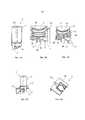
Согласно еще одной форме осуществления настоящего изобретения предусмотрено, что образом крышечный элемент выполнен с возможностью реверсивного соединения с картриджем и, прежде всего, с возможностью фиксации таким образом, что ведущее к емкости отверстие картриджа, по меньшей мере, временно или частично закрыто крышечным элементом, и причем выпускной элемент выполнен с возможностью реверсивного соединения и, прежде всего, с возможностью фиксации с крышечным элементом. Для изготовления этой формы выполнения картриджной системы изготавливают картридж, затем картридж через отверстие картриджа наполняют субстанцией напитка и затем для закрытия отверстия картриджа зажимают приемное устройство картриджа на картридже. В этом случае выпускной элемент имеет, прежде всего, устройство подачи текучей среды, разъем сжатого воздуха, смесительную камеру и выпускное отверстие напитка, в то время как крышечный элемент имеет, прежде всего, выступающий в емкость выпускное отверстие сжатого воздуха для введения сжатого воздуха в емкость. Является возможным, что выпускное отверстие сжатого воздуха содержит полый шип, который находится в действенном соединении с выполненным на крышечном элементе или на впускном элементе разъемом сжатого воздуха.According to a further embodiment of the present invention, it is provided that the lid element is thus reversibly connected to the cartridge and, in particular, is lockable in such a way that the opening of the cartridge leading to the container is at least temporarily or partially covered by the lid element, and moreover, the outlet element is made with the possibility of reversible connection and, above all, with the possibility of fixation with the cover element. To manufacture this embodiment of the cartridge system, a cartridge is made, then the cartridge is filled with a beverage substance through the opening of the cartridge, and then the receptacle of the cartridge is clamped on the cartridge to close the opening of the cartridge. In this case, the outlet element primarily has a fluid supply device, a compressed air connector, a mixing chamber and a beverage outlet, while the lid element primarily has a compressed air outlet protruding into the container for introducing compressed air into the container. ... It is conceivable that the outlet of the compressed air comprises a hollow spike, which is in effective connection with a compressed air connection provided on the cover element or on the inlet element.
Согласно еще одной форме осуществления настоящего изобретения предусмотрено, что посредством вентильного блока является устанавливаемым гидродинамическое соединение между отверстием картриджа и смесительной камерой, причем вентильный блок посредством относительного перемещения между крышечным элементом и выпускным элементом является переводимым из закрытого состояния в открытое состояние для установления гидродинамического соединения. Благоприятным образом, после этого может быть открыт емкость, так что субстанция напитка посредством сжатого воздуха может быть переведена из емкости в смесительную камеру, причем просто реализуется относительное перемещение между крышечным элементом и выпускным элементом. Это относительное перемещение может происходить перед или после вставки картриджной системы в машину приготовления напитков.According to another embodiment of the present invention, it is provided that a fluid connection between the cartridge opening and the mixing chamber is established by means of a valve block, and the valve block, by means of a relative movement between the lid element and the outlet element, is transferred from a closed state to an open state to establish a hydrodynamic connection. Advantageously, the container can then be opened, so that the beverage substance can be transferred by means of compressed air from the container to the mixing chamber, whereby a relative movement between the lid and the outlet is simply realized. This relative movement can occur before or after insertion of the cartridge system into the beverage preparation machine.
Предпочтительно, крышечный элемент имеет ведущее к отверстию картриджа сквозное отверстие, причем вентильный блок образован сквозным отверстием и выступающим в сквозное отверстие выступом выпускного элемента, причем посредством относительного перемещения между крышечным элементом и выпускным элементом выступ перемещается из закрывающего сквозное отверстие положения в частично освобождающее сквозное отверстие положение. Стенка сквозного отверстия снабжена, прежде всего по меньшей мере одним боковым каналом, причем выступ расположен в частично освобождающем сквозное отверстие положении в области по меньшей мере одного бокового канала. Предпочтительно, предусмотрено несколько расположенных параллельно боковых каналов в стенке сквозного отверстия. Боковые каналы проходят вертикально поперечному сечению сквозного отверстия, но при этом простираются в каждом случае только по частичной области стенки. Выступ имеет, прежде всего, внешний обегающий уплотнительный край, который в закрывающем положении прилегает к внутренней стенке сквозного отверстия и, тем самым, закрывает сквозное отверстие. В результате относительного перемещения выступ, предпочтительно, линейно смещается в направлении емкости или от емкости, так что внешний обегающий уплотнительный край попадает в область боковых каналов и теряет свое уплотнительное действие, так как субстанция напитка может обтекать уплотнительный край через боковые каналы.Preferably, the lid element has a through hole leading to the opening of the cartridge, the valve block being formed by a through hole and a protrusion of the outlet element protruding into the through hole, the protrusion being moved from a position covering the through hole to a partially freeing through hole position by relative movement between the lid element and the outlet element ... The wall of the through hole is provided, in particular, with at least one lateral channel, the projection being arranged in a position partially freeing the through hole in the region of the at least one lateral channel. Preferably, a plurality of parallel side channels are provided in the wall of the through hole. The lateral channels extend vertically to the cross-section of the through hole, but in each case only extend over a partial wall region. The protrusion has, in particular, an outer circumferential sealing edge, which in the closing position bears against the inner wall of the through hole and thereby closes the through hole. As a result of the relative movement, the protrusion is preferably displaced linearly in the direction of the container or away from the container, so that the outer circumferential sealing edge enters the region of the side channels and loses its sealing effect, since the beverage substance can flow around the sealing edge through the side channels.
Является возможным, что поперечное сечение боковых каналов и/или количество боковых каналов адаптировано к вязкости субстанции напитка, так что боковые каналы контролируют или же ограничивают поток субстанции напитка в направлении смесительной камеры. При высокой вязкости используется большее число боковых каналов или боковые каналы с большим по размеру поперечным сечением, в то время как при более низкой вязкости предусмотрено меньше боковых каналов или боковые каналы с меньшим поперечным сечением. Из этого следует, что для различных типов субстанций напитков находят применение, предпочтительно, разные крышечные элементы (соответственно с приспособленными боковыми каналами). При этом для каждого картриджа существует подходящий крышечный элемент. Выступ выполнен, прежде всего, в форме наковальни, причем внешний обегающий уплотнительный край образует увеличение поперечного сечения относительно основания наковальни.It is possible that the cross-section of the side channels and / or the number of side channels is adapted to the viscosity of the beverage substance, so that the side channels control or otherwise restrict the flow of the beverage substance towards the mixing chamber. At high viscosities, more side channels or side channels with a larger cross-section are used, while at a lower viscosity there are fewer side channels or side channels with a smaller cross-section. It follows that, for different types of beverage substances, preferably different lid elements (respectively with adapted side channels) are used. In this case, there is a suitable cap element for each cartridge. The protrusion is in particular in the form of an anvil, the outer circumferential sealing edge forming an enlarged cross-section with respect to the base of the anvil.
В описанной выше форме осуществления крышечный элемент и выпускной элемент выполнены как отдельные детали для осуществления относительного перемещение. Относительное перемещение здесь включает в себя, прежде всего, линейное перемещение крышечного элемента и выпускного элемента друг на друга или линейное перемещение крышечного элемента и выпускного элемента друг от друга, чтобы перемещать выступ внутри сквозного отверстия и относительно боковых каналов.In the above-described embodiment, the lid member and the outlet member are formed as separate parts for relative movement. Relative movement here includes primarily linear movement of the lid and outlet against each other, or linear movement of the lid and outlet from each other to move the protrusion within the through hole and relative to the side channels.
Согласно еще одной альтернативной форме осуществления настоящего изобретения предусмотрено, что картридж имеет находящееся в гидродинамическом соединении с емкостью отверстие картриджа, причем отверстие картриджа закрыто уплотнительным элементом, причем уплотнительный элемент содержит, прежде всего, уплотнительную фольгу, которая нанесена и, предпочтительно, напечатана на край отверстия картриджа. В этой форме выполнения приемное устройство картриджа выполнено, прежде всего, неразъемным, то есть отдельные выпускные элементы и крышечные элементы отсутствуют. Для изготовления этой картриджной системы сначала делается картридж с отверстием картриджа, затем картридж через отверстие картриджа наполняется субстанцией напитка, после этого отверстие картриджа закрывается уплотнительным элементом и, наконец, приемное устройство картриджа насаживается зажимом на картридж в области закрытого отверстия картриджа. До, в процессе или после вставки картриджной системы в машину приготовления напитков уплотнительный элемент в области отверстия картриджа должен быть открыт, например, путем перфорации уплотнительной фольги, чтобы субстанция напитка посредством ввода сжатого воздуха могла быть переведена из емкости в смесительную камеру. Предпочтительно, приемное устройство картриджа для этого имеет выступающий в направлении картриджа прокалывающий шип таким образом, что посредством относительного перемещения между приемным устройством картриджа и картриджем прокалывающий шип прокалывает уплотнительный элемент, и образуется гидродинамическое соединение между емкостью и смесительной камерой. Является возможным, что картридж сначала сидит в переднем положении внутри приемного устройства картриджа, в котором прокалывающий шип находится на удалении от уплотнительного элемента, и после введения картриджной системы в машину приготовления напитков переводится из переднего положения в конечное положение, в котором прокалывающий шип пронизывает уплотнительный элемент. При переводе картриджной системы из переднего положения в конечное положение картридж и приемное устройство картриджа, прежде всего, поступательно перемещаются дальше друг к другу, причем уплотнительный элемент при этом перемещении активно прокалывается прокалывающим шипом. Затем прокалывающий шип выступает через уплотнительный элемент в направлении отверстия картриджа. Предпочтительно, в стенке прокалывающего шипа выполняется по меньшей мере один боковой канал для направления субстанции напитка в направлении смесительной камеры, когда проколот уплотнительный элемент. Тогда, по выполненному сбоку на прокалывающем шипе боковому каналу субстанция напитка мимо уплотнительного элемента может течь в направлении смесительной камеры. Предпочтительно, большинство боковых каналов выполнено на прокалывающем шипе. Боковые каналы выполнены, прежде всего, в каждом случае в форме односторонне открытого паза.According to a further alternative embodiment of the present invention, it is provided that the cartridge has an opening of the cartridge which is in fluid communication with the container, the opening of the cartridge being closed by a sealing element, the sealing element comprising primarily a sealing foil which is applied and preferably printed on the edge of the opening cartridge. In this embodiment, the cartridge receptacle is designed in particular one-piece, that is, there are no separate outlet elements and lid elements. For the manufacture of this cartridge system, first a cartridge is made with a cartridge hole, then the cartridge is filled with a beverage substance through the cartridge hole, after which the cartridge hole is closed with a sealing element and, finally, the cartridge receptacle is clamped onto the cartridge in the area of the closed cartridge opening. Before, during or after insertion of the cartridge system into the beverage preparation machine, the sealing element in the area of the cartridge opening must be opened, for example by perforating the sealing foil, so that the beverage substance can be transferred from the container to the mixing chamber by means of compressed air injection. Preferably, the cartridge receptacle for this has a piercing pin protruding in the direction of the cartridge such that, by relative movement between the cartridge receptacle and the cartridge, the piercing pin pierces the sealing element, and a hydrodynamic connection is formed between the container and the mixing chamber. It is possible that the cartridge first sits in a forward position within the cartridge receptacle, in which the piercing pin is at a distance from the sealing element, and, after insertion of the cartridge system into the beverage machine, is moved from the forward position to an end position in which the piercing stud penetrates the sealing element ... When the cartridge system is moved from the forward position to the end position, the cartridge and the cartridge receptacle first of all move further towards each other, the sealing element being actively pierced by a piercing pin during this movement. The piercing pin then protrudes through the sealing member towards the cartridge opening. Preferably, at least one lateral channel is provided in the wall of the piercing bar for directing the beverage substance towards the mixing chamber when the sealing element is punctured. The beverage substance can then flow past the sealing element in the direction of the mixing chamber through a lateral channel formed on the side of the piercing spike. Preferably, most of the side channels are formed on the piercing bar. The side channels are designed primarily in each case in the form of a one-sided open groove.
Является возможным, что поперечное сечение боковых каналов и/или число боковых каналов приведено в соответствие с вязкостью субстанции напитка, так чтобы боковые каналы контролировали или же ограничивали поток субстанции напитка в направлении смесительной камеры. При высокой вязкости используется несколько боковых каналов или боковые каналы с большим поперечным сечением, в то время как при более низкой вязкости предусмотрено меньше боковых каналов или боковые каналы с меньшим поперечным сечением. При этом для каждого картриджа существует подходящее приемное устройство картриджа.It is possible that the cross-section of the side channels and / or the number of side channels is adjusted to the viscosity of the beverage substance so that the side channels control or otherwise restrict the flow of the beverage substance towards the mixing chamber. At high viscosities, several side channels or side channels with a large cross-section are used, while at a lower viscosity there are fewer side channels or side channels with a smaller cross-section. However, there is a suitable cartridge receptacle for each cartridge.
Предпочтительно, прокалывающий шип имеет сквозное отверстие, в котором установлен наконечник сжатого воздуха с возможностью смещения между вдвинутым положением, в котором наконечник сжатого воздуха в направлении емкости не выступает за прокалывающий шип, и выдвинутым положением, в котором наконечник сжатого воздуха выступает за прокалывающий шип в емкость. Предпочтительно, наконечник сжатого воздуха переводится из вдвинутого положения в направлении выдвинутого положения после того, как уплотнительный элемент был перфорирован прокалывающим шипом. Тогда с помощью наконечника сжатого воздуха сжатый воздух вводится в емкость, так что субстанция напитка через пазы вдавливается в смесительную камеру и внутри смесительной камеры с текучей средой образует напиток. Предпочтительно, для этого в наконечник сжатого воздуха интегрирован провод сжатого воздуха. На обращенной, прежде всего, от емкости стороне наконечника сжатого воздуха выполнен разъем для подачи сжатого воздуха, причем разъем для подачи сжатого воздуха, предпочтительно, является доступным снаружи приемного устройства картриджа и таким образом может быть подсоединен к источнику сжатого воздуха машины приготовления напитков. Является возможным, что наконечник сжатого воздуха при вставке картриджной системы в машину приготовления напитков пусковым элементом машины приготовления напитков переводится из вдвинутого положения в выдвинутое положение. Предпочтительно, при этом на наконечник сжатого воздуха уже подается сжатый воздух, чтобы предотвратить какую-либо реконтаминацию. В качестве альтернативы наконечник сжатого воздуха с помощью поданного машиной приготовления напитков сжатого воздуха переводится из вдвинутого положения в выдвинутое положение.Preferably, the piercing pin has a through hole in which the compressed air tip is displaced between a retracted position, in which the compressed air tip does not protrude in the direction of the container from the piercing pin, and an extended position, in which the compressed air tip protrudes beyond the piercing pin into the container ... Preferably, the compressed air tip is moved from the retracted position towards the extended position after the sealing member has been perforated with the piercing pin. Then, by means of a compressed air nozzle, compressed air is introduced into the container, so that the beverage substance is pressed through the grooves into the mixing chamber and forms a beverage with the fluid inside the mixing chamber. Preferably, for this purpose, a compressed air line is integrated into the compressed air tip. On the side of the compressed air tip facing primarily away from the container is a compressed air connector, the compressed air connector preferably being accessible from the outside of the cartridge receptacle and can thus be connected to the compressed air supply of the beverage preparation machine. It is possible that the compressed air tip is moved from the retracted position to the extended position by the trigger element of the beverage preparation machine when the cartridge system is inserted into the beverage preparation machine. Preferably, compressed air is already supplied to the compressed air tip to prevent any recontamination. Alternatively, the compressed air handpiece is moved from the retracted position to the extended position by the compressed air supplied by the beverage preparation machine.
В альтернативном варианте описанной выше формы осуществления прокалывающий шип выполнен не твердым или же цельным на приемном устройстве картриджа, а приемное устройство картриджа вместо этого содержит направляющую шипа и установленный внутри направляющей для шипа с возможностью перемещения прокалывающий шип. Прокалывающий шип расположен с возможностью перемещения относительно направляющей шипа между введенным положением, в котором прокалывающий шип находится на удалении от уплотнительного элемента, и выдвинутым положением, в котором прокалывающий шип прокалывает уплотнительный элемент и выступает в емкость. Внешняя стенка прокалывающего шипа в свою очередь снабжена по меньшей мере одним боковым каналом для направления субстанции напитка в направлении смесительной камеры, когда уплотнительный элемент проколот. По выполненному сбоку на прокалывающем шипе боковому каналу субстанция напитка тогда может течь мимо уплотнительного элемента в направлении смесительной камеры. Предпочтительно, на прокалывающем шипе выполнено несколько боковых каналов. Боковые каналы выполнены, прежде всего, в каждом случае в форме односторонне открытого паза.In an alternative embodiment of the above-described embodiment, the piercing pin is not solid or solid on the cartridge receptacle, but the cartridge receptacle instead comprises a pin guide and a movable piercing pin mounted within the pin guide. The piercing pin is movable relative to the pin guide between an inserted position in which the piercing pin is distant from the sealing member and an extended position in which the piercing pin pierces the sealing member and protrudes into the container. The outer wall of the piercing bar is in turn provided with at least one lateral channel for guiding the beverage substance towards the mixing chamber when the sealing element is punctured. The beverage substance can then flow past the sealing element in the direction of the mixing chamber via a lateral channel formed on the side of the piercing bar. Preferably, a plurality of lateral channels are provided on the piercing pin. The side channels are designed primarily in each case in the form of a one-sided open groove.
Является возможным и при этом выполнении, что поперечное сечение боковых каналов и/или число боковых каналов приспособлено к вязкости субстанции напитка, так что боковые каналы контролируют или же ограничивают поток субстанции напитка в направлении смесительной камеры. При высокой вязкости используют больше боковых каналов или боковые каналы с большим поперечным сечением, в то время как при более низкой вязкости предусмотрено меньше боковых каналов или боковые каналы с меньшим поперечным сечением. При этом для каждого картриджа существует приемное устройство.It is also possible with this embodiment that the cross-section of the side channels and / or the number of side channels is adapted to the viscosity of the beverage substance, so that the side channels control or otherwise restrict the flow of the beverage substance towards the mixing chamber. At high viscosities, more side channels or side channels with a larger cross-section are used, while at a lower viscosity there are fewer side channels or side channels with a smaller cross-section. Moreover, there is a receiving device for each cartridge.
Предпочтительно, и при этом альтернативном выполнении в прокалывающий шип интегрирован трубопровод сжатого воздуха. Правда, прокалывающий шип не имеет подвижного пневмонаконечника, а магистраль сжатого воздуха через неподвижный пневмонаконечник на конце прокалывающего шипа оканчивается в отверстии картриджа. На обращенной, прежде всего, от емкости стороне прокалывающего шипа выполнен разъем сжатого воздуха, причем разъем сжатого воздуха является доступным снаружи приемного устройства картриджа. Предпочтительно, прокалывающий шип при вставке картриджной системы в машину приготовления напитков пусковым элементом машины приготовления напитков переводится из вдвинутого положения в выдвинутое положение. При этом, предпочтительно, уже подается сжатый воздух на пневмонаконечник для предотвращения какой-либо реконтаминации машины приготовления напитков. В качестве альтернативы, пневмонаконечник посредством приложенного машиной приготовления напитков сжатого воздуха перемещается из вдвинутого положения в выдвинутое положение.Preferably, and in this alternative embodiment, a compressed air line is integrated into the piercing pin. True, the piercing pin does not have a movable pneumatic tip, and the compressed air line through the fixed pneumatic tip at the end of the piercing pin ends in the cartridge hole. On the side of the piercing spike facing primarily away from the container, a compressed air connector is provided, the compressed air connector being accessible from the outside of the cartridge receiving device. Preferably, the piercing pin is moved from the retracted position to the extended position by the trigger of the beverage preparation machine when the cartridge system is inserted into the beverage preparation machine. In this case, compressed air is preferably already supplied to the pneumatic handpiece in order to prevent any recontamination of the beverage preparation machine. Alternatively, the pneumatic handpiece is moved from the retracted position to the extended position by the compressed air applied by the beverage preparation machine.
Согласно еще одной предпочтительной форме осуществления настоящего изобретения предусмотрено, что картридж на противолежащей отверстию картриджа стороне имеет другое отверстие картриджа, которое закрыто другим уплотнительным элементом, прежде всего другой уплотнительной фольгой. Благоприятным образом, картридж также может быть изготовлен благоприятным способом литья под давлением.According to a further preferred embodiment of the present invention, it is provided that the cartridge on the side opposite to the opening of the cartridge has another opening of the cartridge, which is covered by another sealing element, in particular another sealing foil. Advantageously, the cartridge can also be manufactured by an advantageous injection molding process.
Согласно одной предпочтительной форме осуществления настоящего изобретения предусмотрено, что картридж и/или приемное устройство картриджа имеет идентификатор продукта, а машина приготовления напитков или приемное устройство картриджа имеет детектор для идентификации идентификатора продукта. Предпочтительно, идентификатор продукта внедрен в штрихкод, RFID-код, QR-код, код матрицы данных, цветовой код, код-голограмму или тому подобное. Благоприятным образом, тем самым становится возможным автоматическое считывание идентификационного кода продукта. Идентификационный детектор содержит, прежде всего, оптический датчик, такой как, например, CCD-камеру, которая автоматически считывает штрихкод или QR-код или код матрицы данных, когда картридж вставлен в машину приготовления напитков. В качестве альтернативы, идентификационный детектор содержит передающую и принимающую антенну для автоматического считывания RFID-кода. Альтернативно является возможным, что код идентификации продукта внедряется и в другие автоматически считываемые компьютерные чипы. Понятие QR-код содержит в смысле настоящего изобретения, прежде всего, любой код матрицы данных. В этом отношении понятия QR-код и код матрицы данных используются синонимично. В качестве альтернативы или дополнительно было бы также возможно, что код идентификации продукта содержит штрихкод, точечный код, бинарный код, код Морзе, код знаков Брайля (шрифт для слепых) или тому подобное. При этом код также может быть внедрен в трехмерную структуру, например, рельеф. Код идентификации продукта содержит, прежде всего, так называемый идентификационный номер продукта, прежде всего универсальный код продукта (UPC), европейский номер изделия (EAN), код GS1, номер изделия глобальной торговли (GTIN) или тому подобное. За счет этого для этого не требуется введение новой кодовой системы. Прежде всего, идентификация продукта происходит под стандартом GS1.According to one preferred embodiment of the present invention, it is provided that the cartridge and / or cartridge receptacle has a product identifier, and the beverage preparation machine or cartridge receptacle has a detector for identifying the product identifier. Preferably, the product identifier is embedded in a barcode, RFID code, QR code, data matrix code, color code, hologram code, or the like. Advantageously, it thereby becomes possible to automatically read the product identification code. The ID detector primarily comprises an optical sensor, such as a CCD camera, which automatically reads a barcode or QR code or data matrix code when the cartridge is inserted into a beverage preparation machine. Alternatively, the ID detector includes a transmitting and receiving antenna for automatically reading the RFID code. Alternatively, it is possible that the product identification code is embedded in other automatically readable computer chips. In the sense of the present invention, the term QR code includes, first of all, any data matrix code. In this regard, the terms QR code and data matrix code are used synonymously. Alternatively or additionally, it would also be possible that the product identification code contains a barcode, a dot code, a binary code, a Morse code, a Braille code (font for the blind), or the like. In this case, the code can also be embedded in a three-dimensional structure, for example, a relief. The product identification code contains primarily a so-called product identification number, primarily a universal product code (UPC), a European product number (EAN), a GS1 code, a global trade product number (GTIN) or the like. This does not require the introduction of a new coding system for this. First of all, the product is identified under the GS1 standard.
Идентификация продукта служит, прежде всего, для того, чтобы указать находящуюся в картридже субстанцию напитка. Во время или перед началом процесса приготовления напитка идентификатор продукта считывается детектором идентификатора. За счет этого со стороны машины приготовления напитка известно, какой вид картриджа вложен в машину приготовления напитков. Является возможным, что блок оценки и управления машины приготовления напитков имеет несколько предварительно заложенных в память программ приготовления напитков, которые предусмотрены для приготовления различных напитков и отличаются друг от друга, например, по подаче, времени подачи, паузам в подаче, температуре, степени карбонизации и/или давлению подводимой текучей среды, отличаются друг от друга. Также является возможным, что при разных программах приготовления напитков находят применение различные подачи сжатого воздуха (например, другое давление). Каждая программа приготовления напитка связана с одним или несколькими идентификаторами продукта. Когда в машину приготовления напитков вводится картридж, идентификатор продукта на картридже считывается детектором идентификатора, а затем сравнивается с предварительно введенными в память данными. Тем самым на основе идентификатора продукта из множества предварительно заложенных в память программ приготовления напитков выбирается программа приготовления напитка, а затем запускается процесс приготовления напитка с помощью выбранной программы приготовления напитка. Такие параметры, как подача, время подачи, паузы в подаче, температура, степень карбонизации и/или давление подводимой текучей среды, задаются или же управляются выбранной программой приготовления напитка, чтобы достигнуть оптимальных результатов для подлежащего приготовлению с соответствующей субстанцией напитка.Product identification primarily serves to indicate the substance of the beverage contained in the cartridge. During or before the start of the beverage preparation process, the product ID is read by the ID detector. As a result, it is known from the side of the beverage preparation machine which type of cartridge is inserted into the beverage preparation machine. It is possible that the evaluation and control unit of the beverage preparation machine has several pre-stored beverage preparation programs that are intended for the preparation of various drinks and differ from each other, for example, in terms of delivery, time of delivery, pauses in delivery, temperature, degree of carbonation and / or the pressure of the supplied fluid differ from each other. It is also possible that different compressed air supplies (eg different pressure) are used for different beverage preparation programs. Each beverage preparation program is associated with one or more product identifiers. When a cartridge is inserted into the beverage preparation machine, the product ID on the cartridge is read by the ID detector and then compared with the previously stored data. This selects a beverage preparation program from a plurality of pre-stored beverage preparation programs based on the product identifier, and then starts the beverage preparation process using the selected beverage preparation program. Parameters such as delivery, delivery time, delivery pauses, temperature, degree of carbonation and / or pressure of the supplied fluid are set or controlled by the selected beverage preparation program in order to achieve optimal results for the beverage to be prepared with the respective beverage substance.
Является возможным, что процесс приготовления напитка не начинается, если не является идентифицируемым код идентификации продукта или идентифицированный код идентификации продукта не подходит ни к какой предварительно заложенной в память программе приготовления напитка. За счет этого предотвращается применение в машине приготовления напитка чуждого системе картриджа, который не сертифицирован для работы в машине для приготовления напитков и при этом существовала бы опасность повреждения машины для приготовления напитков или угрозы пользователю, например, в результате растрескивания картриджа (если он предусмотрен для эксплуатации при меньших давлениях).It is possible that the beverage preparation process does not start if the product identification code is not identifiable or the identified product identification code does not match any pre-stored beverage preparation program. This prevents the use in the beverage preparation machine of a cartridge foreign to the system, which is not certified for operation in the beverage preparation machine, and at the same time there would be a risk of damage to the beverage preparation machine or a threat to the user, for example, by cracking the cartridge (if provided for at lower pressures).
Идентификатор продукта, предпочтительно, наклеен или напечатан на стенку картриджа или на уплотнительный элемент (прежде всего, уплотнительную пленку) для уплотнения отверстия картриджа. Прежде всего, идентификатор продукта позиционирован на картридже таким образом, что идентификатор продукта расположен в пределах области детектирования детектора идентификатора машины приготовления напитков, когда картридж вставлен в машину приготовления напитков. В качестве альтернативы также является возможным, что идентификатор продукта расположен не на картридже, а на внешней стенке приемного устройства картриджа.The product identifier is preferably glued or printed on the wall of the cartridge or on a sealing element (especially a sealing film) to seal the opening of the cartridge. First of all, the product ID is positioned on the cartridge such that the product ID is located within the detection area of the beverage preparation machine ID detector when the cartridge is inserted into the beverage preparation machine. Alternatively, it is also possible that the product identifier is not located on the cartridge, but on the outer wall of the cartridge receptacle.
Еще одним предметом настоящего изобретения для решения поставленной вначале задачи является машина приготовления напитков, в которую является вставляемым картридж согласно изобретению, причем машина приготовления напитков имеет удерживающий блок, в который является вставляемым в соединенное с картриджем приемное устройство картриджа, источник текучей среды для подачи текучей среды в линию для подачи текучей среды, и источник сжатого воздуха для вдувания сжатого воздуха в разъем сжатого воздуха. Предпочтительно, машина приготовления напитков имеет спусковой элемент для перевода наконечника сжатого воздуха или прокалывающего шипа из вдвинутого положения в выдвинутое положение.Another object of the present invention for solving the problem posed at the outset is a beverage preparation machine into which a cartridge according to the invention is inserted, wherein the beverage preparation machine has a holding unit, into which the cartridge receptacle is inserted into the cartridge receptacle connected to the cartridge, a fluid source for supplying fluid into a fluid supply line; and a compressed air source for blowing compressed air into a compressed air connector. Preferably, the beverage preparation machine has a trigger for moving the compressed air tip or piercing pin from a retracted position to an extended position.
Предпочтительно, машина приготовления напитков имеет анализирующий и управляющий блок, который соединен с детектором идентификатора и предусмотрен для определения идентификатора продукта посредством анализа детектированного QR-кода. Предпочтительно, анализирующая электроника определяет из QR-кода GS1 код, который позволяет однозначно идентифицировать расположенный в машине приготовления напитков картридж. Машина приготовления напитков предпочтительно, кроме того, имеет сравнительный блок, который предусмотрен для сравнения определенного идентификатора продукта со списком предварительно заложенных в память идентификаторов продукта и на основе сравнения выбирает программу приготовления напитка. В качестве альтернативы, является возможным, что машина приготовления напитков имеет распознавание алгоритма, которое на основе алгоритма распознает, является ли детектированный QR-код принадлежащим системе (то есть, известным) или чуждым системе. При этом алгоритм функционирует по известным методам криптографического кодирования/декодирования.Preferably, the beverage preparation machine has an analysis and control unit, which is connected to the ID detector and is provided for determining the product ID by analyzing the detected QR code. Preferably, the evaluation electronics determines from the GS1 QR code a code that allows the cartridge located in the beverage preparation machine to be uniquely identified. The beverage preparation machine preferably furthermore has a comparison unit, which is provided for comparing a certain product identifier with a list of pre-stored product identifiers and selects a beverage preparation program based on the comparison. Alternatively, it is possible that the beverage preparation machine has an algorithm recognition which, based on the algorithm, recognizes whether the detected QR code is belonging to the system (ie known) or foreign to the system. In this case, the algorithm functions according to the known methods of cryptographic encoding / decoding.
Еще одним предметом настоящего изобретения для решения поставленной вначале задачи является способ приготовления напитка с помощью соответствующей изобретению картриджной системы, имеющий следующие шаги: вставка картриджной системы в удерживающий блок машины приготовления напитков, перевод субстанции напитка из емкости картриджа в смесительную камеру приемного устройства картриджа посредством устройства опорожнения картриджа, подача текучей среды в смесительную камеру посредством подачи текучей среды, и отвод полученного посредством смешения субстанции напитка с текучей средой напитка через выпускного отверстия напитка. Предпочтительно, при этом субстанция напитка посредством сжатого воздуха переводится из емкости в смесительную камеру.Another object of the present invention for solving the problem posed at the outset is a method for preparing a beverage using the cartridge system according to the invention, having the following steps: inserting the cartridge system into the holding block of the beverage preparation machine, transferring the beverage substance from the cartridge container into the mixing chamber of the cartridge receiving device by means of an emptying device the cartridge, supplying fluid to the mixing chamber by supplying fluid, and discharging the beverage obtained by mixing the beverage substance with the fluid medium through the beverage outlet. Preferably, in this case the beverage substance is transferred from the container to the mixing chamber by means of compressed air.
Предпочтительно, перед подачей в смесительную камеру текучая среда охлаждается и/или насыщается углекислым газом, так что могут изготавливаться прохладительные напитки и газированные безалкогольные напитки.Preferably, the fluid is cooled and / or saturated with carbon dioxide before being fed into the mixing chamber, so that soft drinks and carbonated soft drinks can be prepared.
Согласно еще одной предпочтительной форме осуществления настоящего изобретения предусмотрено, что перед вставкой, при вставке или после вставки картриджной системы в удерживающий блок наконечник сжатого воздуха или прокалывающий шип переводят из вдвинутого положения в выдвинутое положение и перфорируют уплотнительный элемент на отверстии картриджа. Благоприятным образом, при этом емкость автоматически открывается, так что может происходить перевод субстанции напитка в смесительную камеру. Предпочтительно, во время процесса открывания в приемное устройство картриджа уже вводится сжатый воздух и текучая среда, так что предотвращается реконтаминация машины приготовления напитков субстанцией напитка. Перевод наконечника сжатого воздуха и\или прокалывающего шипа происходит, прежде всего, приводным исполнительным органом и/или сжатым воздухом.According to a further preferred embodiment of the present invention, it is provided that before insertion, upon insertion or after insertion of the cartridge system into the holding block, the compressed air tip or piercing pin is moved from the retracted position to the extended position and the sealing element is perforated on the cartridge opening. Advantageously, the container is automatically opened so that the transfer of the beverage substance into the mixing chamber can take place. Preferably, during the opening process, compressed air and fluid are already introduced into the receptacle of the cartridge so that recontamination of the beverage preparation machine with the beverage substance is prevented. The transfer of the compressed air tip and / or the piercing spike takes place, first of all, by the actuator and / or compressed air.
Согласно одной предпочтительной альтернативной форме осуществления настоящего изобретения предусмотрено, что перед вставкой, при вставке или после вставки картриджной системы в удерживающий блок создается гидродинамическое соединение между емкостью и смесительной камерой посредством открывания вентильного блока, вызванного относительным перемещением между крышечным элементом и выпускным элементом. Благоприятным образом, емкость при этом автоматически открывается, так что может происходить перевод субстанции напитка в смесительную камеру. Предпочтительно, во время процесса открывания вентиля в приемное устройство картриджа уже вводится сжатый воздух и текучая среда, так что предотвращается реконтаминация машины приготовления напитков субстанцией напитка. Относительное перемещение вызывается, прежде всего, приводным исполнительным органом или сжатым воздухом.According to one preferred alternative embodiment of the present invention, it is provided that prior to insertion, upon insertion, or after insertion of the cartridge system into the holding block, a fluid connection is created between the container and the mixing chamber by opening the valve block caused by the relative movement between the cover element and the outlet element. Advantageously, the container is then automatically opened so that the transfer of the beverage substance into the mixing chamber can take place. Preferably, during the process of opening the valve, compressed air and fluid are already introduced into the receptacle of the cartridge, so that recontamination of the beverage preparation machine with the beverage substance is prevented. The relative movement is primarily caused by a driven actuator or compressed air.
Дальнейшие детали, признаки и преимущества изобретения вытекают из чертежей, а также из следующего описания предпочтительных форм осуществления на основе чертежей. При этом чертежи иллюстрируют лишь примерные формы осуществления изобретения, которые не ограничивают основную мысль изобретения.Further details, features and advantages of the invention will follow from the drawings and from the following description of preferred embodiments based on the drawings. The drawings illustrate only exemplary embodiments of the invention, which do not limit the basic idea of the invention.
Краткое описание чертежейBrief Description of Drawings
Фиг. 1 показывает основной принцип способа приготовления напитка с приемным устройством картриджа и картриджной системой, вставленной в машину для приготовления напитков согласно примерной форме осуществления настоящего изобретения.FIG. 1 shows the basic principle of a method for preparing a beverage with a cartridge receptacle and a cartridge system inserted into a beverage preparation machine according to an exemplary embodiment of the present invention.
Фиг. 2А-2З показывают схематические виды приемного устройства картриджа и картриджной системы согласно первой форме осуществления настоящего изобретения.FIG. 2A to 2H show schematic views of a cartridge receiver and cartridge system according to a first embodiment of the present invention.
Фиг. 3А-3Ж показывают схематические виды приемного устройства картриджа и картриджной системы согласно о второй форме осуществления настоящего изобретения.FIG. 3A to 3G show schematic views of a cartridge receptacle and cartridge system according to a second embodiment of the present invention.
Фиг. 4А-4В показывают схематические виды приемного устройства картриджа и картриджной системы согласно третьей форме осуществления настоящего изобретения.FIG. 4A-4B show schematic views of a cartridge receiver and cartridge system according to a third embodiment of the present invention.
Фиг. 5А и 5Б показывают схематические виды приемного устройства картриджа и картриджной системы, вставленной в удерживающий блок машины приготовления напитков согласно третьей форме осуществления настоящего изобретения.FIG. 5A and 5B show schematic views of a cartridge receptacle and a cartridge system inserted into a holding block of a beverage preparation machine according to a third embodiment of the present invention.
Формы осуществления изобретенияForms of the invention
На различных фигурах одинаковые детали всегда снабжены одинаковыми ссылочными обозначениями и поэтому, как правило, соответственно называются или же упоминаются только один раз.In the various figures, the same parts are always provided with the same reference numerals and are therefore usually referred to accordingly or referred to only once.
На фиг. 1 показан схематический вид в разрезе соответствующей изобретению картриджной системы 1, которая вставлена в машину 3 приготовления напитков и посредством которой приготавливается напиток 70, чтобы проиллюстрировать общий принцип действия.FIG. 1 shows a schematic sectional view of a
Настоящая система содержит машину 3 приготовления напитков (проиллюстрирована лишь схематически), в которую являются вставляемыми сменные картриджные системы 1. Каждая картриджная система 2 имеет картридж 2, которые наполнены определенной субстанцией 7 напитка. Внутри машины 3 приготовления напитков с помощью субстанции 7 напитка и дополнительного источника воды, в дальнейшем называемого источником 41 текучей среды, производится соответствующий напиток 70. При этом картридж 2, предпочтительно, наполняют предварительно пропорционированным количеством субстанции 7 напитка, которое необходимо для получения целевой питьевой порции, например, стакан желаемого напитка 70. В распоряжении имеется, прежде всего, несколько разных картриджных систем 1, картриджи 2 или же емкости 6 которых для получения различных напитков 70 наполнены разными субстанциями 7 напитков. Если пользователь системы 1 хочет пить определенный напиток 70, ему нужно лишь выбрать из множества различных картриджных систем 1 такую картриджную систему 1, которая содержит соответствующую субстанцию 7 напитка для получения желаемого напитка 70, вставить в удерживающий блок 90 машины 3 приготовления напитков и соответственно запустить процесс приготовления напитка на машине 3 приготовления напитков, например, нажатием пусковой кнопки, соответствующим касанием чувствительного к касанию дисплея, посредством управления жестами или языкового управления или посредством подходящего приложения на мобильном телефоне. Является также возможным, что процесс приготовления напитка начинается автоматически, если опознается вложение новой картриджной системы 1 в удерживающий блок 90. Тогда, в каждом из вышеуказанных случаев желаемый напиток 70 производится автоматически, направляется в питьевой сосуд и обеспечивается пользователю. Затем использованная картриджная система 1 удаляется и утилизируется. Теперь машина 3 приготовления напитков снова готова к наполнению любой новой картриджной системой 1, чтобы изготовить еще один напиток 70.The present system comprises a beverage preparation machine 3 (illustrated only schematically) into which
Субстанция 7 напитка, предпочтительно, содержит жидкие премиксовые компоненты для освежающих напитков, таких как лимонады и соки, содержащие кофеин, углекислоту, фрукты и/или сахар, пивные (смешанные) напитки или прочие алкогольные или неалкогольные (смешанные) напитки.The
Картриджная система 1 содержит картридж 2 в форме цилиндрической емкости с закругленными углами. Емкость полая и при этом содержит емкость 6 для субстанции 7 напитка. Картридж 2 изготовлен, прежде всего, из пластмассы и получен способом дутья в спиртовые формы. Кроме того, картридж 2 имеет отверстие 63 картриджа, через которое емкость 6 наполняется жидкой субстанцией 7 напитка. Дно емкости 6 в данном примере выполнено воронкообразным, причем в центре воронкообразного дна расположено отверстие 63 картриджа. Картридж 2 реверсивно соединен с соответствующим изобретению приемным устройством 10 картриджа, которое после наполнения картриджа 2 в области отверстия 63 картриджа на картридж 2 соединено посредством фиксирующего соединения 50. Для этого приемное устройство 10 картриджа имеет боковые фиксирующие элементы 51 в форме эластичных удерживающих рычажков, которые охватывают расположенный в области отверстия 63 картриджа обегающий удерживающий фланец 52 картриджа 2. Приемное устройство 10 картриджа после наполнения картриджа 2 зажимается на картридже 2.The
Приемное устройство 10 картриджа имеет смесительную камеру 8, которая во время процесса приготовления напитка находится в гидродинамическом соединении с емкостью 6, так что с помощью устройства 34 разгрузки картриджа приемного устройства 10 картриджа субстанция 7 напитка, по меньшей мере, частично может быть переведена из емкости 6 в смесительную камеру 8. Для этой цели устройство 34 разгрузки картриджа содержит магистраль 40 сжатого воздуха. Один конец магистрали 40 сжатого воздуха соединен с разъемом 42 сжатого воздуха, который может быть соединен с источником 41 сжатого воздуха машины 3 приготовления напитков, чтобы вводить сжатый воздух в магистраль 40 сжатого воздуха, в то время как другой конец оканчивается в выпускном отверстии 43 сжатого воздуха, которое открыто в направлении емкости 6 и вводит сжатый воздух в емкость 6. Ввод сжатого воздуха приводит к тому, что субстанция 7 напитка вдавливается в смесительную камеру 8. Далее, в смесительной камере 8 оканчивается устройство 12 подачи текучей среды приемного устройства 10 картриджа, которое питается источником 91 текучей среды машины 3 приготовления напитков. Является возможным, что устройство 12 подачи текучей среды имеет быстродействующую муфту, с помощью которой устройство 12 подачи текучей среды может быть подсоединена к источнику 91 текучей среды машины 3 приготовления напитков. Быстродействующая муфта может быть выполнена, например, так, что при вставке картриджной системы 1 в удерживающий блок 90 автоматически устанавливается гидродинамическое соединение между источником 91 текучей среды и смесительной камерой 8 через устройство 12 подачи текучей среды. Во время процесса приготовления напитков по этой гидродинамической связи текучая среда, прежде всего охлажденная и карбонизированная питьевая вода, попадает из устройства 12 подачи текучей среды в смесительную камеру 8. Кроме того, во время процесса приготовления напитков субстанция 7 напитка попадает из емкости 6 в смесительную камеру 8, как описано выше. В результате смешения субстанции 7 напитка с текучей средой в смесительной камере 8 образуется напиток 70, который затем покидает смесительную камеру 8 через выпускное отверстие 11 напитка.The
Приемное устройство 10 картриджа имеет выпускное отверстие 11 напитка, через который произведенный внутри смесительной камеры 8 напиток 70 покидает смесительную камеру 8 и направляется, прежде всего прямо в питьевой сосуд (не показан), то есть без того, что детали машины 3 приготовления напитков приходят в контакт с напитком 70. За счет этого предотвращается реконтаминация машины 3 приготовления напитков. Питьевой сосуд располагается, прежде всего, прямо под выпускным отверстием 11 напитка.The
После завершения процесса приготовления напитка картриджная система 1 извлекается из удерживающего блока, так что машина 3 приготовления напитка может быть оснащена новой и неиспользованной картриджной системой 1.After the completion of the beverage preparation process, the
Приемное устройство 10 для картриджа может использоваться снова, причем оно отделяется от использованного картриджа 2 путем снятия фиксирующего соединения 50 и крепится зажимом на новом картридже 2.The
В последующем описываются три разных формы выполнения картриджной системы 1. Три разных формы выполнения отличаются, прежде всего, тем, что приемное устройство 10 картриджа выполнено по-разному, и механизм для установления гидродинамического соединения между емкостью 6 и смесительной камерой 8 устроен по-разному, в остальном, все три формы выполнения по существу соответствуют иллюстрированной выше по фиг. 1 картриджной системе 1.In the following, three different embodiments of the
На фиг. 2А-2З иллюстрированы схематические виды приемного устройства 10 картриджа и картриджной системы 1 согласно первой форме осуществления настоящего изобретения.FIG. 2A to 2H illustrate schematic views of a
В этой первой форме осуществления приемное устройство 10 картриджа содержит крышечный элемент 60 и отдельный выпускной элемент 61. Крышечный элемент 60 зажимается прямо на картридже 2 посредством уже поясненного съемного фиксирующего соединения 50. Кроме того, на крышечный элемент 60 зажимается выпускной элемент 61, также с помощью съемного фиксирующего соединения. Смесительная камера 8 и выпускное отверстие 11 напитка интегрированы в выпускной элемент 61. Между крышечным элементом 60 и выпускным элементом 61 выполнен вентильный блок, который закрывает отверстие 63 картриджа и открывается лишь во время процесса приготовления напитка, чтобы сделать возможным перевод субстанции 7 напитка в смесительную камеру 8. Во время процесса приготовления напитка вентильный блок функционирует к тому же как контроль потока, который ограничивает или же управляет потоком субстанции 7 напитка в смесительную камеру 8.In this first embodiment, the
Для выполнения вентильного блока крышечный элемент 60 содержит центральное проходное отверстие 62, которое расположено в области открытого отверстия 63 картриджа и, тем самым, находится в прямой гидродинамической связи с емкостью 6. Выпускной элемент 61 имеет выступ 64, который выступает в проходное отверстие 62. Выступ 64 выполнен в форме наковальни и охватывает внешний обегающий уплотнительный край, который образует увеличение поперечного сечения относительно основания наковальни. За счет относительного перемещения между крышечным элементом 60 и впускным элементом 61 выступ 64 перемещается из закрывающего проходное отверстие 62 положения в частично освобождающее проходное отверстие 62 положение. В закрывающем положении уплотнительный край плотно прилегает к внутренней стенке проходного отверстия 62, так что проходное отверстие 63 закрыто для субстанции 7 напитка. За счет относительного перемещения в данном примере выступ 63 линейно смещается от емкости 6 в направлении смесительной камеры 8, так что внешний обегающий уплотнительный край попадает в область проходного отверстия 63, который снабжен несколькими параллельными боковыми каналами 82. При этом уплотнительное действие уплотнительного края прекращается, так как субстанция 7 напитка теперь может обтекать уплотнительный край через боковые каналы 82 в направлении смесительной камеры 8. Боковые каналы 82 простираются в стенке проходного отверстия 63 в линейном направлении и охватывают соответственно одну односторонне открытую канавку. В соответствии с этим, боковые каналы 82 проходят вертикально поперечному сечению проходного отверстия 63, но при этом простираются в каждом случае только по частичной области стенки, чтобы реализовывалось закрывающее проходное отверстие 62 положение и частично освобождающее проходное отверстие 62 положение.To form the manifold, the lid member 60 comprises a
Поперечное сечение боковых каналов 82 и/или число боковых каналов 82, предпочтительно, адаптировано к вязкости субстанции 7 напитка, так что боковые каналы 82 контролируют или же ограничивают поток субстанции 7 напитка в направлении смесительной камеры 8. При высокой вязкости используются больше боковых каналов 82 и/или боковые каналы 82 с большим поперечным сечением, в то время как при более низкой вязкости предусмотрено меньше боковых каналов 82 и/или боковые каналы 82 с меньшим поперечным сечением.The cross section of the
Относительное перемещение между крышечным элементом 60 и выпускным элементом 61 призводится либо вручную перед вставкой картриджной системы 1 в машину 3 приготовления напитков, либо автоматически во время или после вставки картриджной системы 1 в машину 3 приготовления напитков.The relative movement between the lid member 60 and the outlet member 61 is produced either manually before inserting the
Чтобы процесс приготовления напитков проходил непрерывно, перевод субстанции 7 напитка из емкости 6 в смесительную камеру 8 поддерживается устройством 34 разгрузки картриджа. Устройство 34 разгрузки картриджа в данном примере содержит выпускное отверстие 43 сжатого воздуха, который выполнен в форме выступающего в отверстие 63 картриджа полого шипа. Через этот шип в емкость 6 вдувается сжатый воздух, который вызывает или же ускоряет выход субстанции 7 напитка через боковые каналы 82 в смесительную камеру 8. Сжатый воздух обеспечивается машиной 3 приготовления напитков и через разъем 42 сжатого воздуха вводится в приемное устройство 10 картриджа и посредством магистрали 40 сжатого воздуха направляется на полый шип. Полый шип является частью крышечного элемента 60, в то время как разъем 42 сжатого воздуха и магистраль 40 сжатого воздуха выборочно могут быть выполнены либо в крышечном элементе 60, либо в выпускном элементе 61. За счет этого полый шип как часть крышечного элемента 60 уже находится в гидродинамическом соединении с емкостью 6, прежде чем открывается проходное отверстие 62. К тому же, смесительная камера 8 имеет еще отдельное устройство 12 подачи текучей среды, по которому смесительная камера 8 снабжается, прежде всего, охлажденной и/или карбонизированной питьевой водой. Устройство 12 подачи текучей среды является в данном примере частью выпускного элемента 61.In order for the beverage preparation process to proceed continuously, the transfer of the
Предпочтительно, как источник 91 текучей среды, так и источник 41 сжатого воздуха подсоединяются прямо к устройству устройства 12 подачи текучей среды или же разъему 42 сжатого воздуха, как только картриджная система 1 вставляется в машину 3 приготовления напитков или запускается процесс приготовления напитков и, особенно, прежде чем открывается проходное отверстие 62. За счет этого эффективно предотвращается реконтаминация в направлении машины 3 приготовления напитка, так как устройство 12 подачи текучей среды и устройство 34 разгрузки картриджа сразу при вставке картриджной системы 1 находится под избыточным давлением и, тем самым, предотвращается, что субстанция 7 напитка перемещается в направлении источника 91 текучей среды или же источника 41 сжатого воздуха. За счет этого субстанция 7 напитка, исходя из емкости 6, может двигаться лишь в направлении смесительной камеры 8, как только открывается проходное отверстие 62.Preferably, both the
На фиг. 3А-3Ж иллюстрированы схематические виды приемного устройства 10 картриджа и картриджной системы 1 согласно второй форме осуществления настоящего изобретения.FIG. 3A-3G illustrate schematic views of a
Вторая форма осуществления отличается от первой формы осуществления тем, что приемное устройство 10 картриджа выполнено уже больше не из двух частей (отдельный крышечный элемент 60 и выпускной элемент 61), а состоящим из одной части, то есть крышечный элемент 60 и выпускной элемент 61 выполнены как общая деталь (приемное устройство 10 картриджа), которая зажимается на картридже 2 вышеописанным образом и имеет смесительную камеру 8, выпускное отверстие 11 напитка, устройство 34 опорожнения картриджа и устройство 12 подачи текучей среды. Чтобы во время хранения и транспортировки картриджной системы 1 картридж 2 был герметично закрыт, в настоящей форме осуществления отверстие картриджа 63 закрывается уплотнительным элементом 18 в форме тонкой уплотнительной пленки. После изготовления картриджа 2 способом дутья в распылительные формы уплотнительная пленка наклеивается на край отверстия 63 картриджа или запечатывается (см. фиг. 3А). Лишь после этого приемное устройство 10 картриджа зажимается на картридже 2 (см. фиг. 3Б).The second embodiment differs from the first embodiment in that the
На фиг. 3В показана альтернатива, в которой картридж 2 изготовлен не способом дутья в распылительную форму, а способом формования под давлением. Здесь картридж 2 имеет другое отверстие картриджа, которое закрывается другой уплотнительной пленкой, причем другая уплотнительная пленка 19 аналогично запечатывается на край другого отверстия картриджа. Поскольку здесь необходимы два шага запечатывания, эта альтернатива является менее предпочтительной. Поэтому фиг. 3Г-3Ж опять же основаны на показанном на фиг. 3а и 3Б картридже 2.FIG. 3B shows an alternative in which the
Теперь во второй форме осуществления приемное устройство 10 картриджа имеет жестко стоящий прокалывающий шип 73, который выступает в направлении картриджа 2. В результате относительного перемещения между картриджем 2 и элементом 10 приемного устройства навстречу друг другу прокалывающий шип 73 прокалывает уплотнительный элемент 18. После изготовления картриджной системы 1 сначала картридж 2 сидит в переднем положении внутри приемного устройства 10 картриджа, в котором прокалывающий шип 73 находится на удалении от уплотнительного элемента 18.Now, in the second embodiment, the
Лишь непосредственно перед, во время или сразу после введения картриджной системы 1 в машину 3 приготовления напитков или сразу после ввода процесса приготовления напитка картридж 2 переводится из этого переднего положения в конечное положение, в котором прокалывающий шип 73 пробивает уплотнительный элемент 18. При переводе картриджа 2 из переднего положения в конечное положение картридж 2 и приемное устройство 10 картриджа поступательно перемещаются далее друг к другу, причем уплотнительный элемент 18 при этом перемещении активно прокалывается прокалывающим шипом 73 (ср. фиг. 3Д => фиг. 3Е). Затем прокалывающий шип 73 выступает через уплотнительный элемент 18 в отверстии 63 картриджа в направлении емкости 6. На внешней стороне прокалывающего шипа 73 выполнено несколько боковых каналов, которые выполнены в форме проходящих параллельно друг другу односторонне открытых канавок. После прокалывания уплотнительного элемента 18 боковые каналы 71 попадают в гидродинамическое соединение с емкостью 6, так что субстанция 7 напитка может обтекать края проколотого уплотнительного элемента 18 в направлении смесительной камеры 8.Only immediately before, during or immediately after the introduction of the
Также и при этой форме выполнения поперечное сечение боковых каналов 71 и/или число боковых каналов 71, предпочтительно, адаптировано к вязкости субстанции 7 напитка, так что боковые каналы контролируют или же ограничивают поток субстанции 7 напитка в направлении и смесительной камеры 8. При высокой вязкости используется несколько боковых каналов 71 и/или боковые каналы 71 с большим поперечным сечением, в то время как при меньшей вязкости предусмотрено меньше боковых каналов 71 и/или боковые каналы 71 с меньшим поперечным сечением.Also with this embodiment, the cross-section of the
Прокалывающий шип 73 имеет проходное отверстие, в котором подвижно расположен наконечник 72 сжатого воздуха. Наконечник 72 сжатого воздуха может перемещаться между вдвинутым положением, в котором наконечник 72 сжатого воздуха в направлении емкости 6 не выдается за прокалывающий шип (показан на фиг. 3Е), и выдвинутым положением, в котором наконечник 72 сжатого воздуха выступает за прокалывающий шип 73 вплоть до отверстия 62 картриджа или же в емкость 6 (показан на фиг. 3Ж). В наконечник 72 сжатого воздуха интегрирована магистраль 40 сжатого воздуха, которая соединена с разъемом 42 сжатого воздуха. На обращенной, прежде всего, от емкости 6 стороне наконечника 72 сжатого воздуха выполнен разъем 42 сжатого воздуха, так что он является доступным извне приемного устройства 10 картриджа и может быть подключен прямо к источнику 41 сжатого воздуха машины 3 приготовления напитков.The piercing
Наконечник 72 сжатого воздуха переводится из вдвинутого положения в направлении выдвинутого положения после того, как уплотнительный элемент 18 был перфорирован прокалывающим шипом 73. Затем с помощью наконечника 72 сжатого воздуха в емкость 6 вдувается сжатый воздух, так что субстанция 7 напитка через боковые каналы 71 нагнетается в смесительную камеру 8. Внутри смесительной камеры 8 субстанция 7 напитка смешивается с текучей средой и таким образом образует напиток 70. Является возможным, что наконечник 72 сжатого воздуха при или после вставки картриджной системы 1 в машину 3 приготовления напитков или после запуска процесса приготовления напитка переводится из вдвинутого положения в выдвинутое положение. Это происходит, прежде всего, когда к наконечнику 72 сжатого воздуха прилагается сжатый воздух и таким образом наконечник 72 сжатого воздуха переводится из вдвинутого положения в выдвинутое положение.The
Предпочтительно, как источник 91 текучей среды, так и источник 41 сжатого воздуха подсоединяются прямо к устройству устройства 12 подачи текучей среды или же разъему 42 сжатого воздуха, как только картриджная система 1 вставляется в машину 3 приготовления напитков или запускается процесс приготовления напитка и, прежде всего, перед тем, как прокалывается уплотнительный элемент 18. За счет этого эффективно предотвращается реконтаминация в направлении машины 3 приготовления напитков, так как устройство 12 подачи текучей среды и устройство 34 опорожнения картриджа сразу при вставке картриджной системы 1 находится под избыточным давлением и, тем самым, предотвращается, что субстанция 7 напитка перемещается в направлении источника 91 текучей среды или же источника 41 сжатого воздуха. При этом субстанция 7 напитка, исходя из емкости 6, может двигаться только в направлении смесительной камеры 8, как только открывается уплотнительный элемент 18.Preferably, both the
На фиг. 4А-4В показаны схематические виды приемного устройства 10 картриджа и картриджной системы 1 согласно третьей форме осуществления настоящего изобретения. Третья форма осуществления похожа на показанную на фиг. 3А-3Ж вторую форму осуществления, причем при третьей форме осуществления, в отличие от второй формы осуществления, прокалывающий шип 73 не прочно соединен с приемным устройством 10 картриджа, а вместо этого приемное устройство 10 картриджа имеет направляющую 80 шипа, в которой прокалывающий шип 73 расположен с возможностью перемещения. Уплотнительный элемент 18 здесь открывается не за счет относительного перемещения между картриджем 2 и приемным устройством 10 картриджа, а посредством перевода перемещаемого прокалывающего шипа 73 между вдвинутым положением, в котором прокалывающий шип 73 находится на удалении от уплотнительного элемента (ср. фиг. 4Б) и выдвинутым положением, в котором прокалывающий шип 73 пронизывает уплотнительный элемент 18 (ср. фиг. 4В) и выступает до отверстия 63 картриджа или же в емкость 6.FIG. 4A to 4B show schematic views of a
Внешняя стенка прокалывающего шипа 73 опять же оснащена несколькими боковыми каналами 82 для направления субстанции 7 напитка в направлении смесительной камеры 8, когда проколот уплотнительный элемент 18, как уже было описано при второй форме осуществления. В прокалывающий шип 73, кроме того, интегрирована магистраль 40 сжатого воздуха. Но прокалывающий шип 73 не имеет подвижного наконечника 72 сжатого воздуха, как во второй форме осуществления, а магистраль 40 сжатого воздуха через неподвижно стоящий наконечник 72 сжатого воздуха на конце прокалывающего шипа 73 оканчивается в отверстии 63 картриджа. В этом отношении здесь, в отличие от второй формы осуществления, не требуется смещение наконечника 72 сжатого воздуха относительно прокалывающего шипа 73. Более того, наконечник 72 сжатого воздуха автоматически выступает в проходное отверстие 63, если прокалывающий шип 73 был смещен в выдвинутое положение.The outer wall of the piercing
Снова на обращенной от емкости 6 стороне прокалывающего шипа 73 выполнен разъем 42 сжатого воздуха, который при этом является доступным извне приемного устройства 10 картриджа и подсоединяемым к источнику 41 сжатого воздуха машины 3 приготовления напитков. Предпочтительно, прокалывающий шип 73 при или после вставки картриджной системы 10 в машину 3 приготовления напитков или после запуска процесса приготовления напитка переводится из вдвинутого положения в выдвинутое положение, предпочтительно посредством сжатого воздуха, который при подсоединении источника 41 сжатого воздуха к разъему 42 сжатого воздуха, который выполнен на нижнем конце прокалывающего шипа 73, поступает в устройство 34 опорожнения картриджа.Again, on the side of the piercing
Аналогично второй форме осуществления, и в третьей форме осуществления, предпочтительно, предусмотрено, что как источник 91 текучей среды, так и источник 41 сжатого воздуха подсоединяются прямо к устройству устройства 12 подачи текучей среды или же к разъему 42 сжатого воздуха, как только картриджная система 1 вставляется в машину 3 приготовления напитков или запускается процесс приготовления напитка и, особенно, прежде чем прокалывается уплотнительный элемент 18. За счет этого эффективно предотвращается реконтаминация в направлении машины 3 приготовления напитков, так как устройство 12 подачи текучей среды и устройство 34 опорожнения картриджа сразу при вставке картриджной системы 1 находится под избыточным давлением и, тем самым, предотвращается, что субстанция 7 напитка перемещается в направлении источника 91 текучей среды или же источника 41 сжатого воздуха. При этом субстанция 7 напитка, исходя из емкости 6, может двигаться лишь в направлении смесительной камеры 8, как только открывается уплотнительный элемент 18.Similarly to the second embodiment, and in the third embodiment, it is preferably provided that both the
На фиг. 5А представлен схематический вид приемного устройства 10 картриджа и картриджной системы 1 согласно первой, второй или третьей форме осуществления настоящего изобретения, вставленных в удерживающий блок 90 машины 3 приготовления напитков. На фиг. 5Б показан детальный вид удерживающего блока 90, который по существу состоит из приемного устройства для приемного устройства 10 картриджа, а также содержит идущий к источнику 91 текучей среды машины 3 приготовления напитков провод для присоединения к устройству подачи текучей среды картриджной системы 1.FIG. 5A is a schematic view of a
Далее описываются возможные формы осуществления приемного устройства картриджа согласно изобретению, картриджной системы согласно изобретению, машины приготовления напитков согласно изобретению, а также способа приготовления напитка согласно изобретению.The following describes possible embodiments of a receptacle for a cartridge according to the invention, a cartridge system according to the invention, a beverage preparation machine according to the invention, and a method for preparing a beverage according to the invention.
1 форма осуществления относится к приемному устройству 10 картриджа для приготовления напитка 70 посредством картриджа 2, который содержит наполненную субстанцией 7 напитка емкость 6, причем приемное устройство 10 картриджа выполнено с возможностью вставления в машину 3 приготовления напитков и с возможностью соединения с картриджем 2, причем приемное устройство 10 картриджа имеет выполненную с возможностью приведения в гидродинамическое соединение с емкостью 6 смесительную камеру 8 и оканчивающееся в смесительной камере 8 устройство 12 подачи текучей среды.1 embodiment relates to a receiving
2 форма осуществления относится к приемному устройству 10 картриджа согласно 1 форме осуществления, причем приемное устройство 10 картриджа имеет устройство 34 опорожнения картриджа, которое предусмотрено для, по меньшей мере, частичного перемещения субстанции 7 напитка из емкости 6 в смесительную камеру 8.2, the embodiment relates to a
3 форма осуществления относится к приемному устройству 10 картриджа согласно одной из предшествующих форм осуществления, причем приемное устройство 10 картриджа выполнено с возможностью жесткого или разъемного соединения с картриджем 2 и/или причем смесительная камера 8 в области окончания устройства 12 подачи текучей среды в смесительной камере 8 имеет смесительные структуры.3, the embodiment relates to a
4 форма осуществления относится к приемному устройству 10 картриджа согласно одной из предшествующих форм осуществления, причем устройство 34 опорожнения картриджа содержит разъем 42 сжатого воздуха для подключения к источнику 41 сжатого воздуха и магистраль 40 сжатого воздуха, которая простирается от разъема 42 сжатого воздуха к выпускному отверстию 43 сжатого воздуха, и причем выпускное отверстие 43 сжатого воздуха выступает, прежде всего, в направлении емкости 6 картриджа 2, чтобы вдувать сжатый воздух в емкость 6.4, an embodiment relates to a
5 форма осуществления относится к приемному устройству 10 картриджа согласно 4 форме осуществления, причем устройство 34 опорожнения картриджа выполнено таким образом, что посредством сжатого воздуха субстанция 7 напитка из емкости 6 нагнетается в смесительную камеру 8.5, the embodiment relates to a
6 форма осуществления относится к приемному устройству 10 картриджа согласно одной из предшествующих форм осуществления, причем смесительная камера 8 имеет выпускное отверстие 11 напитка, через который выдается образованный из смеси субстанции 7 напитка с текучей средой напиток, причем приемное устройство 10 картриджа, предпочтительно, выполнено таким образом, что напиток 70 из выпускного отверстия 11 напитка является направляемым прямо в переносимый сосуд.6, the embodiment relates to a
7 форма осуществления относится к приемному устройству 10 картриджа согласно одной из предшествующих форм осуществления, причем приемное устройство 10 картриджа выполнено с возможностью разъемного соединения с картриджем 2 через фиксирующее соединение 50.7, the embodiment relates to a
8 форма осуществления относится к приемному устройству 10 картриджа согласно 7 форме осуществления, причем приемное устройство 10 картриджа имеет эластичные фиксирующие элементы 51, которые захватывают снизу выполненный на картридже 2 удерживающий фланец 52, когда картридж 2 закреплен в приемном устройстве 10 картриджа.
9 форма осуществления относится к приемному устройству 10 картриджа согласно одной из предшествующих форм осуществления, причем приемное устройство 10 картриджа выполнено по существу неразъемным или причем приемное устройство 10 картриджа содержит крышечный элемент 60 и соединенный с крышечным элементом 60 выпускной элемент 61.9, an embodiment relates to a
10 форма осуществления относится к приемному устройству 10 картриджа согласно 9 форме осуществления, причем крышечный элемент 60 выполнен с возможностью реверсивного соединения и, прежде всего, с возможностью фиксации с картриджем 2 таким образом, что ведущее к емкости 6 отверстие 63 картриджа, по меньшей мере, временно или частично закрыто крышечным элементом, и причем выпускной элемент 61 выполнен с возможностью реверсивного соединения и, прежде всего, с возможностью фиксации с крышечным элементом 60.
11 форма осуществления относится к приемному устройству 10 картриджа согласно 10 форме осуществления, причем выпускной элемент 61 имеет устройство 12 подачи текучей среды, разъем 42 сжатого воздуха, смесительную камеру 8 и/или выпускное отверстие 11 напитка.11 the embodiment relates to a
12 форма осуществления относится к приемному устройству 10 картриджа согласно 9 или 11 форм осуществления, причем крышечный элемент 60 имеет выступающее в направлении емкости 6 выпускное отверстие 43 сжатого воздуха, прежде всего в форме полого шипа, который по магистрали 40 сжатого воздуха находится в функциональной связи с выполненным на крышечном элементе 60 или на выпускном элементе 61 разъемом 42 сжатого воздуха.12, the embodiment relates to a
13 форма осуществления относится к приемному устройству 10 картриджа согласно одной из 10-12 форм осуществления, причем посредством вентильного блока является устанавливаемым гидродинамическое соединение между отверстием 63 картриджа и смесительной камерой 8, причем вентильный блок посредством относительного перемещения между крышечным элементом 60 и выпускным элементом 61 является переводимым из закрытого состояния в открытое состояние для установления гидродинамического соединения.13, the embodiment relates to a
14 форма осуществления относится к приемному устройству 10 картриджа согласно одной из 10-13 форм осуществления, причем крышечный элемент 60 имеет ведущее к отверстию 63 картриджа проходное отверстие 62, причем вентильный блок образован проходным отверстием 62 и выступающим через проходное отверстие 62 выступом 64 выпускного элемента 61, причем посредством относительного перемещения между крышечным элементом 60 и выпускным элементом 61 выступ 64 из закрывающего проходное отверстие 62 положения смещается в частично освобождающее проходное отверстие 62 положение.14, the embodiment relates to a
15 форма осуществления относится к приемному устройству 10 картриджа согласно 14 форме осуществления, причем стенка проходного отверстия 62 снабжена по меньшей мере одним боковым каналом 65, и причем выступ 64 расположен в частично освобождающем проходное отверстие 62 положении в области по меньшей мере одного бокового канала 65.15, the embodiment relates to a
16 форма осуществления относится к приемному устройству 10 картриджа согласно одной из 1-9 форм осуществления, причем картридж 2 имеет находящееся в гидродинамическом соединении с емкостью 6 отверстие 63 картриджа, причем отверстие 63 картриджа закрыто уплотнительным элементом 18, причем уплотнительный элемент 18 содержит, прежде всего, уплотнительную пленку, которая нанесена и, предпочтительно, запечатана на край отверстия 63 картриджа.16, the embodiment relates to a
17 форма осуществления относится к приемному устройству 10 картриджа согласно 16 форме осуществления, причем приемное устройство 10 картриджа содержит выступающий в направлении картриджа 2 прокалывающий шип 73 таким образом, что в результате относительного перемещения между приемным устройством 10 картриджа и картриджем 2 прокалывающий шип 73 прокалывает уплотнительный элемент 18, и создается гидродинамическое соединение между емкостью 6 и смесительной камерой 8.17, the embodiment relates to a
18 форма осуществления относится к приемному устройству 10 картриджа согласно 17 форме осуществления, причем в стенке прокалывающего шипа 73 выполнен по меньшей мере один боковой канал 71 для направления субстанции 7 напитка в направлении смесительной камеры 8, когда проколот уплотнительный элемент 18.18, the embodiment relates to a
19 форма осуществления относится к приемному устройству 10 картриджа согласно одной из 16-18 форм осуществления, причем прокалывающий шип 73 имеет проходное отверстие, в котором расположен наконечник 72 сжатого воздуха с возможностью перемещения между вдвинутым положением, в котором наконечник сжатого воздуха не выступает за прокалывающий шип 73 в направлении емкости 6, и выдвинутым положением, в котором наконечник 72 сжатого воздуха выступает за прокалывающий шип 73 в емкость 6.
20 форма осуществления относится к приемному устройству 10 картриджа согласно 19 форме осуществления, причем в наконечник 72 сжатого воздуха интегрирована магистраль 40 сжатого воздуха, и причем на, прежде всего, обращенной от емкости 6 стороне наконечника 72 сжатого воздуха выполнен разъем 42 сжатого воздуха, причем разъем 42 сжатого воздуха является доступным, предпочтительно, извне приемного устройства 10 картриджа.Embodiment 20 relates to a
21 форма осуществления относится к приемному устройству 10 картриджа согласно одной из 19 или 20 форм осуществления, причем наконечник 72 сжатого воздуха при вставке картриджной системы 1 в машину приготовления напитков активирующим элементом машины приготовления напитков переводится из вдвинутого положения выдвинутое положение.Embodiment 21 relates to a
22 форма осуществления относится к приемному устройству 10 картриджа согласно 16 форме осуществления, причем приемное устройство 10 картриджа содержит направляющую 80 шипа и установленный внутри направляющей 80 с возможностью перемещения прокалывающий шип 81, причем прокалывающий шип 81 выполнен с возможностью перемещения между вдвинутым положением, в котором прокалывающий шип 81 находится на удалении от уплотнительного элемента я 19, и выдвинутым положением, в котором прокалывающий шип 81 прокалывает уплотнительный элемент 18 и вдается в емкость 6.22, the embodiment relates to a
23 форма осуществления относится к приемному устройству 10 картриджа согласно 22 форме осуществления, причем во внешней стенке прокалывающего шипа 81 выполнен по меньшей мере один боковой канал 82 для направления субстанции 7 напитка в направлении смесительной камеры 8, когда проколот уплотнительный элемент 18.Embodiment 23 relates to a
24 форма осуществления относится к приемному устройству 10 картриджа согласно одной из 22 или 23 форм осуществления, причем в прокалывающий шип 81 интегрирована магистраль 40 сжатого воздуха, и причем на, прежде всего, обращенной от емкости 6 стороне прокалывающего шипа 81 выполнен разъем 42 сжатого воздуха, причем разъем 42 сжатого воздуха, предпочтительно, является доступным извне приемного устройства 10 картриджа.Embodiment 24 relates to a
25 форма осуществления относится к приемному устройству 10 картриджа согласно одной из 22-24 форм осуществления, причем прокалывающий шип 81 при вставке картриджной системы 1 в машину приготовления напитков активирующим элементом машины приготовления напитков переводится из вдвинутого положения в выдвинутое положение.Embodiment 25 relates to a
26 форма осуществления относится к картриджной системе 1 для приготовления напитка 70, причем картриджная система 1 выполнена с возможностью вставления в машину 3 приготовления напитков, причем картриджная система 1 имеет картридж 2, который содержит наполненную субстанцией 7 напитка емкость 6, и соединенное с картриджем 2 приемное устройство 10 картриджа согласно одной из предшествующих форм осуществления.26, the embodiment relates to a
27 форма осуществления относится к картриджной системе 1 согласно 26 форме осуществления, причем приемное устройство 10 картриджа имеет смесительную камеру 8, устройство 34 опорожнения картриджа, которое предусмотрено для, по меньшей мере, частичного перемещения субстанции 7 напитка из емкости 6 в смесительную камеру 8, и устройство 12 подачи текучей среды, которое оканчивается в смесительной камере 8.Embodiment 27 relates to a
28 форма осуществления относится к картриджной системе 1 согласно 27 форме осуществления, причем картридж 2 жестко или разъемно соединен с приемным устройством 10 картриджа, причем картриджная система 1 выполнена таким образом, что посредством сжатого воздуха субстанция 7 напитка из емкости 6 нагнетается в смесительную камеру 8.Embodiment 28 relates to a
29 форма осуществления относится к картриджной системе 1 согласно 27 или 28 форм осуществления, причем в устройство 12 подачи текучей среды подводится текучая среда, которая охлаждается охлаждающим агрегатом, причем охлаждающий агрегат является частью машины приготовления напитков или находящегося в функциональной связи с машиной приготовления напитков отдельного холодильника.Embodiment 29 relates to a
30 форма осуществления относится к картриджной системе 1 согласно 29 форме осуществления, причем охлаждающий агрегат содержит компрессорный охлаждающий блок, абсорбирующий охлаждающий блок или термоэлектрический охладитель.Embodiment 30 relates to a
31 форма осуществления относится к картриджной системе 1 согласно одной из 27-30 форм осуществления, причем в устройство 12 подачи текучей среды подводится текучая среда, которая посредством карбонизатора смешивается с углекислотой.Embodiment 31 relates to a
32 форма осуществления относится к картриджной системе 1 согласно 31 форме осуществления, причем карбонизатор является частью машины 3 приготовления напитков, и причем карбонизатор имеет приемник для патрона с углекислым газом и подводящее устройство для смешивания текучей среды с углекислым газом из патрона с углекислым газом.Embodiment 32 relates to a
33 форма осуществления относится к картриджной системе 1 согласно одной из 27-32 форм осуществления, причем приемное устройство 10 картриджа разъемно соединено с картриджем 2 посредством фиксирующего соединения 50.Embodiment 33 relates to a
34 форма осуществления относится к картриджной системе 1 согласно 33 форме осуществления, причем приемное устройство 10 картриджа имеет эластичные фиксирующие элементы 51, которые захватывают снизу выполненный на картридже 2 удерживающий фланец 52, когда картридж 2 закреплен в приемном устройстве 10 картриджа.
35 форма осуществления относится к картриджной системе 1 согласно одной из 26-34 форм осуществления, причем картридж 2 имеет находящееся с емкостью 6 в гидродинамическом соединении отверстие 63 картриджа, причем отверстие 63 картриджа закрыто уплотнительным элементом 18, причем уплотнительный элемент 18, прежде всего, содержит уплотнительную пленку, которая нанесена и, предпочтительно, запечатана на край отверстия 63 картриджа.35, the embodiment relates to a
36 форма осуществления относится к картриджной системе 1 согласно одной из 26-35 форм осуществления, причем картридж 2 на противолежащей отверстию 63 картриджа стороне имеет другое отверстие картриджа, которое закрыто другим уплотнительным элементом 10, прежде всего другой уплотнительной пленкой.Embodiment 36 relates to a
37 форма осуществления относится к машине 3 приготовления напитков для приготовления напитка 70, в которую является вставляемой картриджная система 1 согласно одной из форм осуществления 26-36, причем машина 3 приготовления напитков имеет удерживающий блок 90, в который является вставляемым соединенное с картриджем 2 приемное устройство 10 картриджа, источник 91 текучей среды для подачи текучей среды в устройство 12 подачи текучей среды, и источник 41 сжатого воздуха для вдувания сжатого воздуха в разъем 42 сжатого воздуха.37, the embodiment relates to a
38 форма осуществления относится к машине 3 приготовления напитков согласно 37 форме осуществления, причем машина 30 приготовления напитков имеет пусковой элемент для перевода наконечника 72 сжатого воздуха или прокалывающего шипа 81 из вдвинутого положения в выдвинутое положение.Embodiment 38 relates to a
39 форма осуществления относится к способу приготовления напитка 70 с помощью картриджной системы 1 согласно одной из 26-36 форм осуществления, со следующими шагами:Embodiment 39 relates to a method for preparing a
- вставка картриджной системы 1 в удерживающий блок 90 машины 3 приготовления напитков,- inserting the
- перевод субстанции 7 напитка из емкости 6 картриджа 2 в смесительную камеру 8 приемного устройства 10 картриджа посредством устройства 34 опорожнения картриджа,- transfer of the
- подача текучей среды в смесительную камеру 8 посредством устройства 12 подачи текучей среды,- supply of fluid to the mixing
- отвод полученного в смесительной камере 8 путем смешения субстанции 7 напитка с текучей средой напитка 70 посредством выпускного отверстия 11 напитка.- withdrawing obtained in the mixing
40 форма осуществления относится к способу согласно 39 форме осуществления, причем субстанция 7 напитка посредством сжатого воздуха переводится из емкости 6 в смесительную камеру 8.
41 форма осуществления относится к способу согласно 39 или 40 форм осуществления, причем текучая среда перед подачей в смесительную камеру 8 охлаждается и/или насыщается углекислым газом.
42 форма осуществления относится к способу согласно одной из 39-41 форм осуществления, причем перед вставкой, при вставке или после вставки картриджной системы 1 в удерживающий блок 90 наконечник 72 сжатого воздуха или прокалывающий шип 81 переводится из вдвинутого положения в выдвинутое положение и перфорирует уплотнительный элемент 18 на отверстии 63 картриджа.42 embodiment relates to a method according to one of 39-41 embodiments, wherein before insertion, during insertion or after insertion of the
43 форма осуществления относится к способу согласно одной из 39-42 форм осуществления, причем перед вставкой, при вставке или после вставки картриджной системы 1 в удерживающий блок 90 создается гидродинамическое соединение между емкостью 6 и смесительной камерой 8 посредством открытия вентильного блока путем относительного перемещения между крышечным элементом 60 и выпускным элементом 61.43 embodiment relates to a method according to one of 39-42 embodiments, wherein before insertion, upon insertion or after insertion of the
ПЕРЕЧЕНЬ ССЫЛОЧНЫХ ОБОЗНАЧЕНИЙLIST OF REFERENCE SYMBOLS
1 картриджная система1 cartridge system
2 картридж2 cartridge
3 машина приготовления напитков3 beverage preparation machine
6 емкость6 capacity
7 субстанция напитка7 substance of the drink
8 смесительная камера8 mixing chamber
10 приемное устройство картриджа10 cartridge receiver
11 выпускное отверстие напитка11 beverage outlet
12 устройство подачи текучей среды12 fluid supply device
18 уплотнительный элемент18 sealing element
19 другой уплотнительный элемент19 other sealing element
34 устройство опорожнения картриджа34 cartridge emptying device
40 магистраль сжатого воздуха40 compressed air line
41 источник сжатого воздуха41 compressed air sources
42 разъем сжатого воздуха42 compressed air connector
43 выпускное отверстие сжатого воздуха43 compressed air outlet
50 фиксирующее соединение50 locking connection
51 фиксирующие элементы51 fixing elements
52 удерживающий фланец52 holding flange
60 крышечный элемент60 cover element
61 выходной элемент61 output element
62 проходное отверстие62 bore
63 отверстие картриджа63 hole cartridge
64 выступ64 projection
65, 71, 82 боковой канал65, 71, 82 lateral canal
70 напиток70 drink
71 боковой канал71 lateral canal
72 наконечник сжатого воздуха72 compressed air tip
73 прокалывающий шип73 piercing spike
80 направляющая шипа80 stud guide
81 прокалывающий шип81 piercing spike
82 боковой канал82 lateral canal
90 удерживающий блок90 holding block
91 источник текучей среды.91 sources of fluid.
Claims (23)
Translated fromRussianApplications Claiming Priority (12)
| Application Number | Priority Date | Filing Date | Title |
|---|---|---|---|
| DE102016200254 | 2016-01-12 | ||
| DE102016200254.6 | 2016-01-12 | ||
| DE102016212012 | 2016-07-01 | ||
| DE102016212012.3 | 2016-07-01 | ||
| DE102016212013 | 2016-07-01 | ||
| DE102016212013.1 | 2016-07-01 | ||
| DE102016218509.8 | 2016-09-27 | ||
| DE102016218507.1 | 2016-09-27 | ||
| DE102016218509 | 2016-09-27 | ||
| DE102016218507 | 2016-09-27 | ||
| DE102016218884.4 | 2016-09-29 | ||
| DE102016218884 | 2016-09-29 |
Related Parent Applications (1)
| Application Number | Title | Priority Date | Filing Date |
|---|---|---|---|
| RU2018129054ADivisionRU2744424C2 (en) | 2016-01-12 | 2017-01-12 | Cartridge receiving device, cartridge system, beverage-making machine and beverage preparation method |
Publications (1)
| Publication Number | Publication Date |
|---|---|
| RU2739334C1true RU2739334C1 (en) | 2020-12-23 |
Family
ID=57796360
Family Applications (13)
| Application Number | Title | Priority Date | Filing Date |
|---|---|---|---|
| RU2018128360ARU2731493C2 (en) | 2016-01-12 | 2017-01-12 | Cartridge receiving device, cartridge system, beverage preparation machine and beverage preparation method |
| RU2020116542ARU2739371C1 (en) | 2016-01-12 | 2017-01-12 | Beverage preparation system, cartridge and beverage preparation unit |
| RU2018128660ARU2725774C2 (en) | 2016-01-12 | 2017-01-12 | Cartridge receiving device, cartridge system, beverage preparation machine and beverage preparation method |
| RU2020116550ARU2746240C1 (en) | 2016-01-12 | 2017-01-12 | Dispensing apparatus with cartridge holder, system and method of beverage preparation |
| RU2018128570ARU2720570C2 (en) | 2016-01-12 | 2017-01-12 | Cartridge receiving device for beverage cartridge or food product |
| RU2018128718ARU2719693C2 (en) | 2016-01-12 | 2017-01-12 | Cartridge for beverage substrate or food product |
| RU2020116548ARU2755088C1 (en) | 2016-01-12 | 2017-01-12 | Pouring apparatus with cartridge holder, system and method for preparing beverage |
| RU2018128620ARU2742642C2 (en) | 2016-01-12 | 2017-01-12 | Dispensing device with cartridge holder |
| RU2020116554ARU2751585C1 (en) | 2016-01-12 | 2017-01-12 | Pouring apparatus with a cartridge holder |
| RU2018129054ARU2744424C2 (en) | 2016-01-12 | 2017-01-12 | Cartridge receiving device, cartridge system, beverage-making machine and beverage preparation method |
| RU2020117477ARU2741289C1 (en) | 2016-01-12 | 2017-01-12 | Cartridge receiving device with sealing film opened by movable piercing prick equipped with air line |
| RU2018128700ARU2741893C2 (en) | 2016-01-12 | 2017-01-12 | System, cartridge, beverage preparation unit and beverage preparation method |
| RU2020117475ARU2739334C1 (en) | 2016-01-12 | 2017-01-12 | Cartridge receiving device with sealing film opened by relative movement |
Family Applications Before (12)
| Application Number | Title | Priority Date | Filing Date |
|---|---|---|---|
| RU2018128360ARU2731493C2 (en) | 2016-01-12 | 2017-01-12 | Cartridge receiving device, cartridge system, beverage preparation machine and beverage preparation method |
| RU2020116542ARU2739371C1 (en) | 2016-01-12 | 2017-01-12 | Beverage preparation system, cartridge and beverage preparation unit |
| RU2018128660ARU2725774C2 (en) | 2016-01-12 | 2017-01-12 | Cartridge receiving device, cartridge system, beverage preparation machine and beverage preparation method |
| RU2020116550ARU2746240C1 (en) | 2016-01-12 | 2017-01-12 | Dispensing apparatus with cartridge holder, system and method of beverage preparation |
| RU2018128570ARU2720570C2 (en) | 2016-01-12 | 2017-01-12 | Cartridge receiving device for beverage cartridge or food product |
| RU2018128718ARU2719693C2 (en) | 2016-01-12 | 2017-01-12 | Cartridge for beverage substrate or food product |
| RU2020116548ARU2755088C1 (en) | 2016-01-12 | 2017-01-12 | Pouring apparatus with cartridge holder, system and method for preparing beverage |
| RU2018128620ARU2742642C2 (en) | 2016-01-12 | 2017-01-12 | Dispensing device with cartridge holder |
| RU2020116554ARU2751585C1 (en) | 2016-01-12 | 2017-01-12 | Pouring apparatus with a cartridge holder |
| RU2018129054ARU2744424C2 (en) | 2016-01-12 | 2017-01-12 | Cartridge receiving device, cartridge system, beverage-making machine and beverage preparation method |
| RU2020117477ARU2741289C1 (en) | 2016-01-12 | 2017-01-12 | Cartridge receiving device with sealing film opened by movable piercing prick equipped with air line |
| RU2018128700ARU2741893C2 (en) | 2016-01-12 | 2017-01-12 | System, cartridge, beverage preparation unit and beverage preparation method |
Country Status (22)
| Country | Link |
|---|---|
| US (18) | US11148926B2 (en) |
| EP (22) | EP3517494B1 (en) |
| JP (19) | JP6882333B2 (en) |
| KR (18) | KR20180121499A (en) |
| CN (18) | CN110577180A (en) |
| AU (18) | AU2017207774B2 (en) |
| BR (7) | BR112018014087A2 (en) |
| CA (17) | CA3011183A1 (en) |
| DK (9) | DK3517486T3 (en) |
| ES (16) | ES2939370T3 (en) |
| FI (6) | FI3674257T3 (en) |
| HR (3) | HRP20210168T1 (en) |
| HU (14) | HUE061337T2 (en) |
| IL (16) | IL260524B (en) |
| PH (14) | PH12018501482A1 (en) |
| PL (19) | PL3517493T3 (en) |
| PT (9) | PT3402737T (en) |
| RS (3) | RS61386B1 (en) |
| RU (13) | RU2731493C2 (en) |
| SG (18) | SG10202004045YA (en) |
| WO (7) | WO2017121796A1 (en) |
| ZA (17) | ZA201805339B (en) |
Families Citing this family (56)
| Publication number | Priority date | Publication date | Assignee | Title |
|---|---|---|---|---|
| ES2939370T3 (en) | 2016-01-12 | 2023-04-21 | Freezio Ag | Dispensing system with cartridge holder |
| CH712695A1 (en) | 2016-07-07 | 2018-01-15 | Mühlemann Ip Gmbh | One-serving pack for making a beverage from a beverage concentrate. |
| DE112017005622T5 (en)* | 2016-11-08 | 2019-07-25 | Ngk Insulators, Ltd. | Process for drying a separation membrane and process for producing a separation membrane structure |
| CN113859780B (en)* | 2016-12-01 | 2024-03-01 | 贝德福德系统有限责任公司 | System for beverage production |
| US11643269B2 (en) | 2016-12-01 | 2023-05-09 | Bedford Systems, LLC | Container and opening arrangement for beverage production |
| WO2019002293A1 (en)* | 2017-06-26 | 2019-01-03 | Freezio Ag | DEVICE FOR PRODUCING A DRINK |
| HRP20220532T1 (en) | 2017-11-27 | 2022-06-10 | Freezio Ag | Cartridge receptacle, cartridge system, beverage preparation machine, and method for producing a beverage |
| WO2019183474A1 (en)* | 2018-03-22 | 2019-09-26 | Bedford Systems Llc | Reconstitution of independent beverage flows |
| CN112040820A (en)* | 2018-03-22 | 2020-12-04 | 贝德福德系统有限责任公司 | pod assembly for beverage machine |
| CA3094751A1 (en) | 2018-03-22 | 2019-09-26 | Bedford Systems Llc | Puncture mechanism for beverage machine |
| CN108577560B (en)* | 2018-04-30 | 2020-06-26 | 瑞安市捷达机械制造有限公司 | Movable water drinking device for office |
| SG11202102708UA (en)* | 2018-10-25 | 2021-05-28 | Nestle Sa | Pack for preparing food or beverage products |
| WO2020089404A1 (en)* | 2018-11-01 | 2020-05-07 | Société des Produits Nestlé S.A. | Capsule system with recognition means and adaptable opening and injection mechanism |
| WO2020097558A1 (en) | 2018-11-08 | 2020-05-14 | Bedford Systems Llc | Multi-use beverage system |
| CA3147474A1 (en)* | 2019-07-15 | 2021-01-21 | Freezio Ag | Cartridge receptacle, cartridge system, beverage preparation machine, and method for producing a beverage |
| US20220232859A1 (en)* | 2019-07-22 | 2022-07-28 | Good Design, Inc. | Beverage dispensing apparatus and methods for preparing beverages |
| WO2021018760A1 (en) | 2019-07-26 | 2021-02-04 | Freezio Ag | Cartridge system and method for producing a cartridge system |
| GB201912089D0 (en) | 2019-08-22 | 2019-10-09 | Diageo Ireland | A beverage dispense apparatus and method relating to same |
| US20220287495A1 (en) | 2019-08-22 | 2022-09-15 | Freezio Ag | Cartridge System and Method for Producing a Cartridge System |
| US20220297930A1 (en)* | 2019-09-18 | 2022-09-22 | II Angelo PETRINI | Improved capsule for the infusion of drinks |
| AU2020354429A1 (en)* | 2019-09-23 | 2022-03-10 | Carlsberg Breweries A/S | RFID-equipped pressure chamber for keg |
| AU2020383624B2 (en) | 2019-11-14 | 2024-05-02 | Product Ventures, Ltd. | Automated pet food dispenser |
| KR20220108121A (en)* | 2019-12-04 | 2022-08-02 | 소시에떼 데 프로듀이 네슬레 소시에떼아노님 | Fluid handling device for beverage making machine |
| PH12022551128A1 (en)* | 2019-12-04 | 2023-08-23 | SociaTa Des Produits Nestla S A | Beverage preparation machine |
| US11337438B2 (en)* | 2020-01-15 | 2022-05-24 | Coldsnap, Corp. | Rapidly cooling food and drinks |
| EP4188806A1 (en)* | 2020-07-30 | 2023-06-07 | Société des Produits Nestlé S.A. | Beverage preparation system |
| WO2022084475A1 (en) | 2020-10-22 | 2022-04-28 | Freezio Ag | Cartridge system; beverage preparation machine; and process for manufacturing a cartridge system |
| JP7471208B2 (en)* | 2020-12-02 | 2024-04-19 | 株式会社 ゼンショーホールディングス | Juice supplying device, juice supplying method and program |
| CA3202180A1 (en) | 2021-01-07 | 2022-07-14 | Marc Kruger | Cartridge receptacle, cartridge system, beverage preparation system and method for preparing a beverage |
| JP2024510592A (en)* | 2021-03-11 | 2024-03-08 | フリーツィオ、アクチエンゲゼルシャフト | Beverage preparation machines and beverage preparation systems with locking means and coupling elements |
| CN117083240A (en)* | 2021-03-11 | 2023-11-17 | 弗里奇奥股份公司 | Beverage preparation machine with actuator and beverage preparation system |
| GB202104233D0 (en)* | 2021-03-25 | 2021-05-12 | Edwards Harrison | Brewing cartridge |
| HUE070492T2 (en) | 2021-03-25 | 2025-06-28 | Freezio Ag | Cartridge to be inserted in a beverage preparing apparatus, method for using such a cartridge |
| EP4370466A1 (en) | 2021-07-15 | 2024-05-22 | Freezio AG | Cartridge system comprising a cartridge closed by a valve |
| US11647860B1 (en) | 2022-05-13 | 2023-05-16 | Sharkninja Operating Llc | Flavored beverage carbonation system |
| US12096880B2 (en) | 2022-05-13 | 2024-09-24 | Sharkninja Operating Llc | Flavorant for beverage carbonation system |
| US11751585B1 (en) | 2022-05-13 | 2023-09-12 | Sharkninja Operating Llc | Flavored beverage carbonation system |
| AU2022457789A1 (en) | 2022-05-13 | 2024-11-21 | Sharkninja Operating Llc | Agitator for a carbonation system |
| US12213617B2 (en)* | 2022-05-13 | 2025-02-04 | Sharkninja Operating Llc | Flavored beverage carbonation process |
| DE102022115715A1 (en) | 2022-06-23 | 2023-12-28 | Pressure Wave Systems Gmbh | Compressor device and cooling device with compressor device |
| US12005404B2 (en) | 2022-08-22 | 2024-06-11 | Sharkninja Operating Llc | Beverage carbonation system flow control |
| CN218683765U (en)* | 2022-11-01 | 2023-03-24 | 康富(天津)有限公司 | Beverage machine |
| US11745996B1 (en) | 2022-11-17 | 2023-09-05 | Sharkninja Operating Llc | Ingredient containers for use with beverage dispensers |
| US11634314B1 (en) | 2022-11-17 | 2023-04-25 | Sharkninja Operating Llc | Dosing accuracy |
| US12103840B2 (en) | 2022-11-17 | 2024-10-01 | Sharkninja Operating Llc | Ingredient container with sealing valve |
| US11738988B1 (en) | 2022-11-17 | 2023-08-29 | Sharkninja Operating Llc | Ingredient container valve control |
| US12084334B2 (en) | 2022-11-17 | 2024-09-10 | Sharkninja Operating Llc | Ingredient container |
| USD1092208S1 (en) | 2022-12-23 | 2025-09-09 | Sharkninja Operating Llc | Cap of ingredient container |
| USD1091308S1 (en) | 2022-12-23 | 2025-09-02 | Sharkninja Operating Llc | Ingredient container |
| US11871867B1 (en) | 2023-03-22 | 2024-01-16 | Sharkninja Operating Llc | Additive container with bottom cover |
| US12116257B1 (en) | 2023-03-22 | 2024-10-15 | Sharkninja Operating Llc | Adapter for beverage dispenser |
| US11925287B1 (en) | 2023-03-22 | 2024-03-12 | Sharkninja Operating Llc | Additive container with inlet tube |
| US12005408B1 (en) | 2023-04-14 | 2024-06-11 | Sharkninja Operating Llc | Mixing funnel |
| WO2025018455A1 (en)* | 2023-07-19 | 2025-01-23 | 주식회사 만상코리아 | Cup lid capable of keeping beverage concentration constant |
| WO2025045731A1 (en)* | 2023-08-25 | 2025-03-06 | Société des Produits Nestlé S.A. | Piercing and fluid processing device |
| WO2025099239A1 (en)* | 2023-11-09 | 2025-05-15 | Freezio Ag | Piercing spike, cartridge holder, system for preparing a drink, method for preparing a drink, and use of a piercing spike |
Citations (5)
| Publication number | Priority date | Publication date | Assignee | Title |
|---|---|---|---|---|
| US3685694A (en)* | 1969-12-18 | 1972-08-22 | Yan Nell Corp | Liquid dispenser plastic bottle and receptacle with piercing units |
| WO1981000098A1 (en)* | 1979-07-02 | 1981-01-22 | Tannetics Inc | Beverage dispensing device and container therefor |
| WO2007035820A2 (en)* | 2005-09-19 | 2007-03-29 | Jmf Group Llc, D/B/A Al's Beverage Company | Beverage dispensing system and method |
| WO2014200481A1 (en)* | 2013-06-12 | 2014-12-18 | Nestec S.A. | Mixing nozzle |
| WO2015094774A1 (en)* | 2013-12-16 | 2015-06-25 | Bov Solutions, Inc. | Dispenser platform apparatus and method |
Family Cites Families (255)
| Publication number | Priority date | Publication date | Assignee | Title |
|---|---|---|---|---|
| LU57420A1 (en) | 1968-11-02 | 1969-03-04 | ||
| SE378409B (en)* | 1968-12-18 | 1975-09-01 | Kantor Int Sa | |
| US3904083A (en) | 1974-04-19 | 1975-09-09 | Gen Electric | Self-sealing viscous material dispenser loading apparatus |
| US4098434A (en) | 1975-06-20 | 1978-07-04 | Owens-Illinois, Inc. | Fluid product dispenser |
| US4012823A (en)* | 1975-12-08 | 1977-03-22 | American Optical Corporation | Method of making artificial intraocular lenses |
| SU1071220A3 (en) | 1978-05-05 | 1984-01-30 | , Луиджи Гольо и Альдо Бас сети (Итали ) | Device for preparing and dispensing drink |
| US4216885A (en) | 1978-10-20 | 1980-08-12 | The Coca-Cola Company | Disposable package for dispensing liquids with a controlled rate of flow |
| US4306667A (en)* | 1979-10-12 | 1981-12-22 | The Coca-Cola Company | Post-mix beverage dispensing system syrup package, valving system, and carbonator therefor |
| US4376496A (en) | 1979-10-12 | 1983-03-15 | The Coca-Cola Company | Post-mix beverage dispensing system syrup package, valving system, and carbonator therefor |
| US4408701A (en)* | 1980-04-16 | 1983-10-11 | Cadbury Schweppes Plc | Liquid dispensing valve |
| US4363424A (en)* | 1980-10-23 | 1982-12-14 | Cadbury Schweppes Pcl | Quick coupling device for a gas pressurization system |
| DK162369C (en) | 1982-07-19 | 1992-03-23 | Mars G B Ltd | METHOD AND DISPENSES FOR THE PREPARATION OF AN INFUSIONAL BEVERAGE |
| JPS6181991A (en)* | 1984-09-28 | 1986-04-25 | 日世冷機株式会社 | Feeder for drink liquid |
| US4708266A (en) | 1986-03-21 | 1987-11-24 | The Coca-Cola Company | Concentrate dispensing system for a post-mix beverage dispenser |
| CA1280903C (en) | 1987-05-30 | 1991-03-05 | Hirosato Takeuchi | Dispenser |
| JPH0424949Y2 (en)* | 1988-02-29 | 1992-06-12 | ||
| JPH01226387A (en) | 1988-03-07 | 1989-09-11 | Nitto Denko Corp | Thermal recording material and method |
| JP2656935B2 (en)* | 1988-03-08 | 1997-09-24 | キリンビバレッジ株式会社 | Dispenser with bag-in-box |
| GB8806666D0 (en) | 1988-03-21 | 1988-04-20 | Gen Foods Ltd | Method for preparing beverages & beverage preparing machines |
| JPH01254597A (en)* | 1988-04-05 | 1989-10-11 | Sanden Corp | Mixing valve device of post-mix carbonated beverage dispensing device |
| SE462713B (en) | 1988-04-27 | 1990-08-20 | Drinx Productions Ab | DOSAGE AND MIXING DEVICE |
| CN88205971U (en)* | 1988-05-20 | 1988-12-28 | 罗宁 | Bulk beer retail device |
| US4901890A (en)* | 1988-06-24 | 1990-02-20 | Mivelaz Michael B | Watering system automatic additive dispenser kit |
| JPH0279300A (en)* | 1988-09-16 | 1990-03-19 | Sanyo Electric Co Ltd | Sound recording/reproducing device |
| US5025953A (en)* | 1988-10-17 | 1991-06-25 | Doundoulakis George J | Deformable beverage containers for preserving carbonation |
| JPH049360Y2 (en) | 1988-11-30 | 1992-03-09 | ||
| JPH02269696A (en)* | 1989-04-04 | 1990-11-05 | Sanyo Electric Co Ltd | Beverage supply apparatus |
| US4984711A (en)* | 1989-10-23 | 1991-01-15 | Ellis Charles V | Wine dispenser |
| DK533789D0 (en) | 1989-10-26 | 1989-10-26 | Torben Peter Petersen | ICE MACHINE FOR DINING WITH ROTATING MIX ORGAN |
| US6460734B1 (en) | 1990-06-06 | 2002-10-08 | Lancer Partnership | Dispensing apparatus including a pump package system |
| US5842603A (en)* | 1990-06-06 | 1998-12-01 | The Coca-Cola Company | Postmix juice dispenser |
| CN1042415C (en)* | 1990-06-23 | 1999-03-10 | 伊索沃思有限公司 | Apparatus for making or dispensing drinks |
| US5301838A (en) | 1991-01-23 | 1994-04-12 | Continental Pet Technologies, Inc. | Multilayer bottle with separable inner layer and method for forming same |
| US5897899A (en)* | 1991-05-08 | 1999-04-27 | Nestec S.A. | Cartridges containing substances for beverage preparation |
| TW199884B (en) | 1991-05-08 | 1993-02-11 | Sociere Des Produits Nestle S A | |
| JPH05138101A (en)* | 1991-11-21 | 1993-06-01 | Kawasaki Steel Corp | Dropping device for high-viscosity coating material |
| JPH05270592A (en) | 1992-03-25 | 1993-10-19 | Hidefusa Kudo | Cartridge device for liquid |
| JP2591744Y2 (en) | 1993-01-20 | 1999-03-10 | ノードソン株式会社 | Dispenser for liquid discharge with liquid enclosing cartridge storage case |
| US5425404A (en)* | 1993-04-20 | 1995-06-20 | Minnesota Mining And Manufacturing Company | Gravity feed fluid dispensing system |
| US5494194A (en) | 1993-12-10 | 1996-02-27 | White Consolidated Industries, Inc. | Viscous material dispenser |
| JPH07309397A (en)* | 1994-05-12 | 1995-11-28 | Sanyo Electric Co Ltd | Bag-in-box undiluted solution extracting device |
| US5876995A (en) | 1996-02-06 | 1999-03-02 | Bryan; Bruce | Bioluminescent novelty items |
| JPH10245099A (en) | 1997-03-06 | 1998-09-14 | Fuji Electric Co Ltd | Beverage dispenser |
| US5836482A (en)* | 1997-04-04 | 1998-11-17 | Ophardt; Hermann | Automated fluid dispenser |
| US5992685A (en)* | 1998-01-23 | 1999-11-30 | The Coca-Cola Company | Fountain dispensing module |
| GB2335412B (en) | 1998-03-18 | 2003-03-05 | Alan David Somerfield | Improved fluid dispenser |
| DE29825074U1 (en) | 1998-10-08 | 2004-09-09 | Sumitomo Rubber Industries Ltd., Kobe | Sealing equipment, for inflatable object e.g. tyre, has gas source connector, that allows sealant container to be removed |
| US6689108B2 (en) | 1998-11-13 | 2004-02-10 | Elan Pharma International Limited | Device for measuring a volume of drug |
| US6267496B1 (en)* | 1998-12-03 | 2001-07-31 | Bryan Real | Beverage supply apparatus for dispensing machine |
| US6079315A (en) | 1999-01-19 | 2000-06-27 | Keurig, Inc. | Beverage filter cartridge holder |
| AU3666000A (en) | 1999-04-08 | 2000-11-14 | Crossflow International Limited | Method and apparatus for dispensing viscous material |
| US7597922B2 (en) | 1999-05-18 | 2009-10-06 | Nestec S.A. | System for dispensing a liquid beverage concentrate |
| SE515590C2 (en) | 1999-09-24 | 2001-09-03 | Asept Int Ab | Process and apparatus for making beverages on which foam is to be formed |
| DE69910053T2 (en) | 1999-12-01 | 2004-04-15 | The Procter & Gamble Company, Cincinnati | Device for product delivery |
| AUPQ450999A0 (en) | 1999-12-07 | 2000-01-06 | Perna Pty Ltd | Storage and dispensing of carbonated beverages |
| EP1118301A1 (en)* | 2000-01-19 | 2001-07-25 | Cws International Ag | Soap solution dispensing device in a dispenser |
| NL1015368C2 (en)* | 2000-05-31 | 2001-12-12 | Heineken Tech Services | Beverage dispensing assembly as well as container for beverage, in particular carbonated beverage, and beverage dispensing conduit for use in such an assembly. |
| US6896159B2 (en) | 2000-06-08 | 2005-05-24 | Beverage Works, Inc. | Beverage dispensing apparatus having fluid director |
| JP4552969B2 (en)* | 2000-08-24 | 2010-09-29 | 日本軽金属株式会社 | Anaerobic opener for beverage containers |
| US20030036725A1 (en)* | 2000-09-21 | 2003-02-20 | Gilad Lavi | Reconstitution and injection system |
| FR2815328B1 (en) | 2000-10-17 | 2002-12-20 | Biodome | CONNECTION DEVICE BETWEEN A CONTAINER AND A CONTAINER AND READY-TO-USE ASSEMBLY COMPRISING SUCH A DEVICE |
| US6740345B2 (en) | 2000-12-22 | 2004-05-25 | Edward Zhihua Cai | Beverage making cartridge |
| US6554165B2 (en)* | 2001-03-15 | 2003-04-29 | Cactrus Drink Systems Inc. | Beverage dispenser |
| EP1247481B1 (en)* | 2001-04-03 | 2004-11-17 | Societe Des Produits Nestle S.A. | Extraction apparatus with integrated cartridge supply system |
| US6606938B2 (en) | 2001-04-06 | 2003-08-19 | Keurig, Incorporated | Two step puncturing and venting of single serve filter cartridge in a beverage brewer |
| US6655260B2 (en) | 2001-04-11 | 2003-12-02 | Keurig, Incorporated | Beverage filter cartridge holder |
| ITTO20010902A1 (en) | 2001-09-21 | 2003-03-21 | Sgl Italia Srl | COFFEE MACHINE'. |
| NL1019054C2 (en)* | 2001-09-28 | 2003-03-31 | Heineken Tech Services | Beverage dispensing device provided with a double closure. |
| JP2003141625A (en)* | 2001-11-06 | 2003-05-16 | Fuji Electric Co Ltd | Cup-type beverage vending machine |
| CA2421128C (en)* | 2002-03-14 | 2008-05-20 | Robert Hale | Beverage cartridge and filter assembly |
| CA2432814C (en)* | 2003-06-19 | 2012-05-08 | Hygiene-Technik Inc. | Manual or pump assist fluid dispenser |
| CA2484926C (en)* | 2002-05-06 | 2013-07-16 | Bunn-O-Matic Corporation | Spray head |
| CN1313896C (en)* | 2002-06-13 | 2007-05-02 | 荷兰联合利华有限公司 | Beverage dispenser |
| US20040055472A1 (en) | 2002-09-24 | 2004-03-25 | Sto Corporation | One-cup coffee brewer |
| NZ540479A (en) | 2002-11-29 | 2007-03-30 | Interbrew Sa | Beer dispensing system with gas pressure reservoir |
| US7097074B2 (en)* | 2003-01-24 | 2006-08-29 | Kraft Foods R&D, Inc. | Machine for the preparation of beverages |
| US7316178B2 (en) | 2003-01-24 | 2008-01-08 | Kraft Foods R & D, Inc. | Machine for the preparation of beverages |
| CA2513765C (en) | 2003-01-24 | 2012-08-07 | Steven Carter | Cartridge for the preparation of beverages and method of manufacturing a cartridge |
| JP4402687B2 (en) | 2003-01-24 | 2010-01-20 | クラフト・フーヅ・リサーチ・アンド・ディベロップメント・インコーポレイテッド | Machine for preparing beverages |
| MXPA05008160A (en) | 2003-01-31 | 2005-10-06 | Nestec Sa | VISCOSE FOOD AND DRINK DISPENSING SYSTEM. |
| US6959839B2 (en)* | 2003-02-10 | 2005-11-01 | Donna Roth | Flavoring component holding dispenser for use with consumable beverages |
| US6971549B2 (en)* | 2003-04-18 | 2005-12-06 | S.C. Johnson & Son, Inc. | Bottle adapter for dispensing of cleanser from bottle used in an automated cleansing sprayer |
| US20050001095A1 (en)* | 2003-05-05 | 2005-01-06 | Christensen Donald J. | Self-aligning thrust reverser system lock assembly |
| ATE517841T1 (en) | 2003-05-06 | 2011-08-15 | Carlsberg Breweries As | METHOD FOR PRODUCING A BEVERAGE DISPENSER |
| US6955116B2 (en)* | 2003-06-13 | 2005-10-18 | Robert Hale | Beverage dispensing machine including cartridge ejector assembly |
| US8327754B2 (en)* | 2003-07-22 | 2012-12-11 | The Coca-Cola Company | Coffee and tea pod |
| DK1500357T3 (en) | 2003-07-23 | 2006-06-19 | Monodor Sa | Process for preparing a beverage from a capsule and device for initiating the process |
| ATE529027T1 (en)* | 2003-08-25 | 2011-11-15 | Nestec Sa | METHOD AND DEVICE FOR PRODUCING A BEVERAGE FROM A CAPSULE CONTAINING A SUBSTANCE |
| CA2536986C (en) | 2003-08-25 | 2012-11-20 | Henry Macler | Portable water cooler for use with bagged fluids and bagged fluids for use therewith |
| US6983863B2 (en)* | 2003-08-28 | 2006-01-10 | Lancer Partnership, Ltd. | Method and apparatus for beverage dispensing nozzle |
| US7234787B2 (en) | 2004-01-08 | 2007-06-26 | Eastman Kodak Company | Liquid level detection method and apparatus |
| DE102004004314B4 (en) | 2004-01-28 | 2014-05-15 | Tchibo Gmbh | Brewing device for a coffee machine |
| CN1997585B (en) | 2004-02-13 | 2013-11-06 | 美商智高咖啡公司 | Liquid concentrate/extract beverage dispenser with replaceable concentrate/extract cartridge |
| US7651015B2 (en)* | 2004-02-13 | 2010-01-26 | Intelligent Coffee Company, Llc | Liquid concentrate/extract beverage dispenser with replaceable concentrate/extract cartridge |
| GB2413480B (en)* | 2004-02-17 | 2006-08-30 | Kraft Foods R & D Inc | An insert and a system for the preparation of beverages |
| EP1579793B1 (en) | 2004-03-26 | 2007-07-11 | ILLYCAFFE' S.p.A. | Beverage extraction assembly for extracting a beverage from a particulate substance contained in a cartridge |
| JP4727658B2 (en) | 2004-05-05 | 2011-07-20 | コロムブス イー.エーピーエス | Disposable compounding equipment |
| US7347345B2 (en) | 2004-06-02 | 2008-03-25 | Nestec S.A. | Device and method for hygienically delivering a liquid food |
| ES2348020T3 (en)* | 2004-07-09 | 2010-11-26 | Nestec S.A. | SYSTEM AND DEVICE FOR THE PREPARATION AND SUPPLY OF FOOD PRODUCTS FROM A COMPOSITE MIXTURE OF A FOOD LIQUID AND A DILUENT. |
| JP4349985B2 (en) | 2004-07-15 | 2009-10-21 | フジテクノ株式会社 | Beverage server and connection for beverage server |
| GB2416757A (en)* | 2004-08-06 | 2006-02-08 | Imi Vision Ltd | Apparatus for dispensing a flowable foodstuff |
| US20060047250A1 (en) | 2004-08-30 | 2006-03-02 | Hickingbotham Dyson W | Fluid delivery device |
| US7661352B2 (en)* | 2004-08-31 | 2010-02-16 | Nestec S.A. | Method and system for in-cup dispensing, mixing and foaming hot and cold beverages from liquid concentrates |
| NL1029155C2 (en)* | 2004-10-19 | 2006-04-20 | Sara Lee De Nv | System and method for preparing a drink suitable for consumption. |
| CN101080358B (en)* | 2004-10-19 | 2016-02-10 | 皇家戴维艾格伯茨有限公司 | Systems and methods for preparing beverages fit for consumption |
| US20060115570A1 (en)* | 2004-11-30 | 2006-06-01 | Guerrero Arturo F | Beverage dispenser with variable-concentration additive dispensing |
| US7621426B2 (en) | 2004-12-15 | 2009-11-24 | Joseph Kanfer | Electronically keyed dispensing systems and related methods utilizing near field frequency response |
| JP4419854B2 (en)* | 2005-01-21 | 2010-02-24 | 富士電機リテイルシステムズ株式会社 | Drinking water dispenser |
| US20060249536A1 (en) | 2005-05-09 | 2006-11-09 | Hartman Eric E | Device and method for dispensing a food product using a reclosable resilient valve |
| US20060278657A1 (en)* | 2005-06-14 | 2006-12-14 | Roatis Calin V | Concentrate dispensing units and disposable concentrate packages including impeller pumps |
| US7651010B2 (en)* | 2005-09-23 | 2010-01-26 | Nestec S.A. | Food dispenser with pump for dispensing from a plurality of sources |
| EP1806314A1 (en)* | 2006-01-09 | 2007-07-11 | Nestec S.A. | Device for dispensing a beverage with a controlled air inlet, and method therefor |
| NL1033412C2 (en)* | 2006-02-17 | 2007-11-13 | Meccano Asia Ltd | Package for preparation of food product e.g. beverage, includes reservoir and mixing element which are produced monolithically by injection molding |
| NL1031177C2 (en) | 2006-02-17 | 2007-08-20 | Meccano Asia Ltd | Package for preparation of food product e.g. beverage, includes reservoir and mixing element which are produced monolithically by injection molding |
| US7905373B2 (en)* | 2006-03-06 | 2011-03-15 | Deka Products Limited Partnership | System and method for generating a drive signal |
| NL1031622C2 (en)* | 2006-04-19 | 2007-10-22 | Sara Lee De Nv | System for preparing a drink suitable for consumption, as well as an exchangeable holder for such a system. |
| NL1032081C2 (en) | 2006-04-19 | 2007-10-22 | Sara Lee De Nv | Beverage preparation system, container and device. |
| EP1908706B1 (en) | 2006-06-06 | 2009-12-23 | Nestec S.A. | Capsule with reduced dripping |
| JP5012160B2 (en) | 2006-06-13 | 2012-08-29 | 富士電機リテイルシステムズ株式会社 | Beverage extractor |
| DE502007003099D1 (en) | 2006-08-25 | 2010-04-22 | Delica Ag | MEANS FOR PENETRATING A PORTION PACKAGING CONTAINING EXTRACTION GOODS, DEVICE FOR EXTRACTING THE EXTRACTION GUN CONTAINED IN THE PORTION PACKAGING, AND METHOD FOR PRODUCING THE MEDIUM |
| ITMI20061989A1 (en) | 2006-10-17 | 2008-04-18 | Maddalena Ricotti | INFUSION APPARATUS FOR COFFEE MACHINE AND RELATED DRIVING METHOD |
| NL1032893C2 (en)* | 2006-11-17 | 2008-05-20 | Heineken Supply Chain Bv | Container for dispensing liquor. |
| EP2129618A4 (en) | 2006-12-18 | 2011-04-20 | Avishai Hatuka | System for the preparation and distribution of beverages in a transportation unit |
| ES2661027T3 (en)* | 2007-01-15 | 2018-03-27 | Swiss Caffe Asia Ltd. | Capsule, means of penetration of the bottom of a capsule and device for preparing a beverage |
| PL1967099T3 (en) | 2007-03-06 | 2010-06-30 | Nestec Sa | Device for preparing a food liquid from a capsule |
| ATE431712T1 (en) | 2007-03-06 | 2009-06-15 | Nestec Sa | SYSTEM FOR PRODUCING A BEVERAGE FROM A CAPSULE AND METHOD |
| DE602007008214D1 (en) | 2007-06-05 | 2010-09-16 | Criali Invest Sa | Process for the preparation of a drink and device and capsule for the application of this method |
| CN101742918A (en)* | 2007-06-11 | 2010-06-16 | 艾斯普瑞西股份有限公司 | Portable brewing device and method of making and operating same |
| EP2017220B1 (en)* | 2007-07-19 | 2010-09-15 | Nestec, Ltd. | Device for dispensing a liquid |
| EP2017221A1 (en) | 2007-07-19 | 2009-01-21 | Nestec, Ltd. | Device for dispensing a liquid |
| ES2348931T3 (en) | 2007-07-19 | 2010-12-17 | Nestec, Ltd. | DEVICE FOR DISPENSING A LIQUID. |
| DK2181063T3 (en)* | 2007-08-20 | 2012-04-02 | Carlsberg Breweries As | Modular pressure distribution system for beverages and module therefor |
| MX2010002673A (en)* | 2007-09-06 | 2010-06-01 | Deka Products Lp | Product dispensing system. |
| CN201105986Y (en)* | 2007-10-16 | 2008-08-27 | 犍为一中外国语实验学校 | Edible oil quantitative dispenser |
| PT2080454E (en)* | 2008-01-18 | 2010-08-27 | Nestec Sa | Beverage machine and piercing member for an opening device of a beverage machine |
| EP2082975A1 (en)* | 2008-01-23 | 2009-07-29 | Rychiger AG | Capsule for infusion beverages. |
| EP2265156B1 (en) | 2008-03-14 | 2013-05-15 | Mocoffee AG | Apparatus and capsule for making a drink |
| DE102008021778A1 (en)* | 2008-04-30 | 2009-11-05 | Eugster/Frismag Ag | Process for the preparation and administration of milk froth or a beverage, device for carrying out the process, espresso machine with such a device and preparation vessel for use in such a device or espresso machine |
| DE102008021777A1 (en) | 2008-04-30 | 2009-11-05 | Eugster/Frismag Ag | Process for the preparation of a drink and beverage preparation device for carrying out the method |
| US8522841B2 (en)* | 2008-06-11 | 2013-09-03 | Enpulz, L.L.C. | Soft drink container supporting additive containment and selective release |
| EP2837580B1 (en) | 2008-08-29 | 2018-10-10 | PepsiCo, Inc. | Post-mix beverage system comprising a cartridge having two chambers |
| US9272827B2 (en) | 2008-08-29 | 2016-03-01 | Pepsico, Inc. | Post-mix beverage system |
| IT1391885B1 (en)* | 2008-11-03 | 2012-01-27 | Hausbrandt Trieste 1892 Spa | PERFORATOR DEVICE FOR CAPSULES AND MACHINE FOR THE PREPARATION OF DRINKING DRINKS SUCH A DEVICE. |
| EP2184259A1 (en)* | 2008-11-05 | 2010-05-12 | Carlsberg Breweries A/S | Pressure generating device for beverage dispensing system |
| WO2010080707A1 (en)* | 2009-01-09 | 2010-07-15 | Vitality Foodservice, Inc. | Coupling for pump and container |
| PT2210826E (en)* | 2009-01-22 | 2012-09-21 | Nestec Sa | Capsule with integrated piercing member and system for preparing a beverage |
| PT2236437E (en) | 2009-03-31 | 2012-04-13 | Nestec Sa | Capsule with filter for preparing a liquid nutritional or food composition and related beverage production system |
| CA2757509A1 (en) | 2009-04-15 | 2010-10-21 | Luna Technology Systems Lts Gmbh | Device for discharging an extraction product out of a portion packaging; puncturing device and extraction apparatus |
| GB2469873B (en)* | 2009-05-01 | 2011-09-07 | Kraft Foods R & D Inc | Beverage preparation machines |
| SA110310345B1 (en) | 2009-05-05 | 2013-12-30 | Nestec Sa | Capsule for Preparing a Nutritional Product Including a Water Filter |
| PT2966007T (en) | 2009-06-17 | 2017-12-20 | Douwe Egberts Bv | Capsule, system and method for preparing a predetermined quantity of beverage suitable for consumption |
| AU2010297421A1 (en) | 2009-09-23 | 2012-04-12 | Nestec S.A. | Container holding assembly and receiving assembly adapted for connecting a container to a machine |
| AU2010305408B2 (en) | 2009-10-08 | 2016-06-30 | Société des Produits Nestlé S.A. | Portioned system for preparing a nutritional product |
| IT1396016B1 (en) | 2009-10-15 | 2012-11-09 | Swiss Caffe Asia Ltd | INFUSION DEVICE FOR INFUSION AND SIMILAR CAPSULES, PARTICULARLY FOR ESPRESSO AND SIMILAR COFFEE MACHINES. |
| DE102009049945A1 (en)* | 2009-10-19 | 2011-04-21 | Krüger Gmbh & Co. Kg | Brewing device and method for extracting a portion capsule |
| DE102009052513A1 (en)* | 2009-11-11 | 2011-05-12 | K System Gmbh | Brewing device for extracting portion capsule, particularly preparation of hot drinks, has brewing chamber elements, where brewing chamber elements are at distance from each other between loading position and extraction position |
| BR112012011161A8 (en)* | 2009-11-12 | 2019-02-12 | Formulanow Llc | punching, cartridge and mixing equipment and method for combining mixing and liquid |
| GB2475291B (en) | 2009-11-12 | 2012-03-28 | Kraft Foods R & D Inc | Beverage preparation machines |
| AU2010339892A1 (en) | 2009-12-16 | 2012-07-05 | Intelligent Coffee Company, Llc | Pump and appliances containing a pump |
| CN102843938B (en) | 2010-02-01 | 2016-01-20 | 库里格绿山股份有限公司 | Method and apparatus for cartridge-based carbonation of beverages |
| WO2011091542A1 (en)* | 2010-02-01 | 2011-08-04 | Medmix Systems Ag | Device for removing a fluid from a vial |
| US9936834B2 (en) | 2010-02-01 | 2018-04-10 | Bedford Systems Llc | Method and apparatus for cartridge-based carbonation of beverages |
| CN102970906B (en)* | 2010-02-17 | 2017-03-15 | 皇家戴维艾格伯茨有限公司 | Coffee bean packaging cartridge and the coffee beverage system including it |
| ES2398896T3 (en) | 2010-03-30 | 2013-03-22 | Capitani S.R.L. | Capsule or pod for the production of an infused beverage |
| CN101897544B (en) | 2010-03-31 | 2012-02-15 | 宁波西文电器有限公司 | Coffee machine capable of making coffee package fallen off automatically |
| EP2384996A1 (en) | 2010-05-04 | 2011-11-09 | Luna Technology Systems LTS GmbH | Capsule for coffee, method for its production and device for brewing coffee |
| JP2011235905A (en)* | 2010-05-06 | 2011-11-24 | Sakagami Kogyo Kk | Floating prevention device for synthetic resin bottle in drinking water dispenser |
| TW201200433A (en) | 2010-05-06 | 2012-01-01 | Brita Gmbh | Container and device with such a container |
| DK2571405T3 (en) | 2010-05-19 | 2014-06-23 | Nestec Sa | BEVERAGE MAKING CAPSULES |
| DE102010044945A1 (en) | 2010-05-28 | 2011-12-01 | Eugster/Frismag Ag | Brewing device for extracting a portion capsule, method for operating a brewing device, method for producing a brewing device and use of a brewing device |
| GB2481068B (en)* | 2010-06-11 | 2012-06-20 | Kraft Foods R & D Inc | Cartridge for the preparation of beverages |
| ES2907932T3 (en) | 2010-07-16 | 2022-04-27 | Nestle Sa | Device for the preparation of a drink by centrifugation |
| WO2012019903A1 (en) | 2010-08-13 | 2012-02-16 | Sara Lee/De B.V. | Device, system and method for preparing a beverage suitable for consumption from a capsule |
| US8505777B2 (en) | 2010-08-16 | 2013-08-13 | Lancer Corporation | Method and apparatus for a sanitizable mixing nozzle |
| DE102011012881A1 (en)* | 2010-09-22 | 2012-03-22 | Krüger Gmbh & Co. Kg | Portion capsule and method of making a beverage with a portion capsule |
| JP5909494B2 (en)* | 2010-10-08 | 2016-04-26 | コーニンクレッカ フィリップス エヌ ヴェKoninklijke Philips N.V. | Extraction unit using horizontal motion |
| JP3164948U (en)* | 2010-10-12 | 2010-12-24 | 慎一 矢野 | Needle for water server |
| US8646379B2 (en) | 2010-11-15 | 2014-02-11 | Conair Corporation | Brewed beverage appliance and method |
| EP2651270B1 (en) | 2010-12-16 | 2017-02-15 | Briggo, LLC | Apparatus and method for brewed and espresso drink generation |
| CN202186881U (en)* | 2011-01-13 | 2012-04-11 | 阮志燕 | Oil filling device |
| AU2012213611A1 (en) | 2011-01-31 | 2013-07-25 | Nestec S.A. | Beverage production machine comprising features to facilitate capsule loading and unloading |
| US8596498B2 (en) | 2011-05-02 | 2013-12-03 | Mouse Trap Design, Llc | Mixing and dispensing device |
| US20140130678A1 (en) | 2011-06-01 | 2014-05-15 | Alain Frydman | Capsule for pressurized drink extraction |
| CN102838076A (en)* | 2011-06-23 | 2012-12-26 | 可口可乐公司 | Close over assembly and beverage distributor provided with same |
| JP5514777B2 (en)* | 2011-08-03 | 2014-06-04 | 富士山の銘水株式会社 | Punching device for drinking water packaging bag in water server |
| AU2012290003A1 (en) | 2011-08-03 | 2014-02-27 | Keurig Green Mountain, Inc. | Method and apparatus for cartridge-based carbonation of beverages |
| ITRE20110065A1 (en) | 2011-09-05 | 2013-03-06 | Raimondi Spa | LEVELING SPACER DEVICE FOR INSTALLING LASTRIFORM FACTS FOR SURFACE COATING |
| DE102011053294A1 (en) | 2011-09-06 | 2013-03-07 | Eugster/Frismag Ag | Method and device for producing a coffee preparation |
| EP2782485B1 (en) | 2011-09-09 | 2018-10-24 | Fountain Master, LLC | Beverage maker |
| DE102011086420A1 (en) | 2011-11-15 | 2013-05-16 | BSH Bosch und Siemens Hausgeräte GmbH | Cartridge receptacle for a brewing chamber of a hot beverage vending machine based on dimensionally stable beverage cartridges |
| CN103202653B (en)* | 2012-01-17 | 2015-07-15 | 唐锋机电科技(深圳)有限公司 | Jiuce extractor |
| ITTO20120061A1 (en) | 2012-01-25 | 2013-07-26 | Lavazza Luigi Spa | SYSTEM AND MACHINE FOR THE PREPARATION OF DRINKS WITH THE USE OF CAPSULES |
| BR112014018853A8 (en) | 2012-02-02 | 2017-07-11 | Sodastream Ind Ltd | CAPSULE FOR STORING A FIXED AMOUNT OF SYRUP; SYRUP RELEASE METHOD FROM A CAPSULE INTO A BOTTLE OF SOAR WATER |
| GB2499004A (en) | 2012-02-02 | 2013-08-07 | Kraft Foods R & D Inc | Clamping mechanism for a beverage preparation machine |
| AU2013217593B9 (en) | 2012-02-09 | 2017-02-16 | Keurig Green Mountain, Inc. | Beverage forming device and method with moving beverage cartridge holder |
| CN104254268B (en) | 2012-02-09 | 2018-03-20 | 库里格绿山股份有限公司 | Beverage forming apparatus and method with actuation button |
| MY185241A (en) | 2012-02-09 | 2021-04-30 | Keurig Green Mountain Inc | Beverage forming device and method with cartridge retainer |
| US8622246B2 (en)* | 2012-02-13 | 2014-01-07 | Ecolab Usa Inc. | Fluid reservoir docking station |
| US9365405B2 (en)* | 2012-02-17 | 2016-06-14 | Gus Stratton | Beverage dispensing system |
| US20130224340A1 (en) | 2012-02-27 | 2013-08-29 | Hanan BenDavid | Optimal extraction rate coffee capsule with effective seal for diverse group heads |
| EP2819560B1 (en) | 2012-02-29 | 2015-10-07 | Nestec S.A. | Filtration unit for use in machine for preparing ready-to-drink nutritional liquids |
| US9795245B2 (en) | 2012-03-14 | 2017-10-24 | Hamilton Beach Brands, Inc. | Kitchen appliance for preparing a beverage and method of operating same |
| GB201204999D0 (en) | 2012-03-21 | 2012-05-02 | Bacardi & Company Ltd | Method and system for providing drinks, drinks container and drinks device |
| KR102075814B1 (en) | 2012-06-22 | 2020-02-10 | 터치 커피 & 베버리지스, 엘엘씨. | Beverage brewing system |
| US20140079856A1 (en)* | 2012-06-29 | 2014-03-20 | Darren Hatherell | Beverage Carbonating System and Method for Carbonating a Beverage |
| WO2014008926A1 (en)* | 2012-07-10 | 2014-01-16 | Foster Jody James | System for the preparation of nursing bottles |
| US20140013958A1 (en) | 2012-07-12 | 2014-01-16 | Select Brands, Inc. | Hybrid coffee maker with multiple brewing modes |
| DE102012108653A1 (en) | 2012-08-20 | 2014-02-20 | Eugster/Frismag Ag Elektrohaushaltgeräte | Brewing device and method for operating a brewing device |
| WO2014041539A2 (en)* | 2012-09-13 | 2014-03-20 | Strauss Water Ltd. | Beverage dispensing apparatus with a carbonation system |
| JP2014076814A (en)* | 2012-10-09 | 2014-05-01 | Muramoto Kosakusho:Kk | Water server |
| JP2016502414A (en) | 2012-10-12 | 2016-01-28 | ネステク ソシエテ アノニム | Card for containing food or beverage ingredients |
| NL2009864C2 (en)* | 2012-11-22 | 2014-05-27 | Heineken Supply Chain Bv | Beverage dispensing assembly and container for use in a beverage dispensing assembly. |
| ITTO20121076A1 (en)* | 2012-12-14 | 2014-06-15 | Lavazza Luigi Spa | CAPSULE OR POD AND INFUSION GROUP FOR THE PREPARATION OF A BEVERAGE, IN PARTICULAR COFFEE |
| US9415990B2 (en)* | 2013-02-13 | 2016-08-16 | Cryovac, Inc. | Bag-in-box system for use in dispensing a pumpable product |
| NL2011917C2 (en)* | 2013-02-20 | 2014-12-18 | At Venture B V | SYSTEM FOR PREPARING A DRINK AND METHOD FOR THIS. |
| US20140245893A1 (en) | 2013-03-02 | 2014-09-04 | Robert Bao Vu | Methods, apparatus and products for grinding brewable materials into a filter cartridge |
| US10524609B2 (en)* | 2013-03-14 | 2020-01-07 | Altria Client Services Llc | Disposable beverage pod and apparatus for making a beverage |
| CA2905217C (en) | 2013-04-03 | 2016-11-08 | 2266170 Ontario Inc. | Capsule machine and components |
| CN105473031B (en) | 2013-05-10 | 2018-11-02 | 竹斯柔公司 | Juicing system and method |
| US10154752B2 (en)* | 2013-05-23 | 2018-12-18 | 2266170 Ontario Inc. | Capsule housing |
| JP6240006B2 (en) | 2013-06-05 | 2017-11-29 | シャープ株式会社 | Image forming apparatus |
| DE102013110121A1 (en)* | 2013-09-13 | 2015-03-19 | Krones Ag | Disposable emptying system for containers |
| GB201318315D0 (en) | 2013-10-16 | 2013-11-27 | Sab Miller Plc | Dispensing apparatus |
| ZA201409085B (en)* | 2013-12-11 | 2015-11-25 | Bergen Broodryk | Fluid dispensing apparatus and system |
| JP2015134645A (en) | 2013-12-16 | 2015-07-27 | パナソニックIpマネジメント株式会社 | Beverage dispenser |
| JP6150725B2 (en)* | 2013-12-27 | 2017-06-21 | サントリーホールディングス株式会社 | Dilution bottle and beverage delivery device |
| BR112016015443B1 (en) | 2014-01-03 | 2021-09-28 | Koninklijke Douwe Egberts B.V. | SYSTEM FOR PREPARATION OF DRINK CONSUMPTION, DOSING, PARTS KIT, REPLACEABLE REFILLS, AND METHOD FOR POSITIONING AT LEAST ONE REPLACEABLE REFILLS |
| US9474406B2 (en) | 2014-01-17 | 2016-10-25 | Keurig Green Mountain, Inc. | Apparatus with beverage cartridge holder having movable outlet |
| US10136754B2 (en) | 2014-01-17 | 2018-11-27 | Keurig Green Mountain, Inc. | Beverage machine cartridge holder |
| US9462911B2 (en) | 2014-02-03 | 2016-10-11 | Aroma Polti Sa | Coffee machine for preparation of coffee |
| US9788682B2 (en) | 2014-02-25 | 2017-10-17 | Newco Enterprises, Inc. | Beverage brewing device for automatically brewing and dispensing single cup quantities of beverage through a vending machine with minimal manual participation |
| WO2015148710A1 (en) | 2014-03-26 | 2015-10-01 | Secor Water, Llc | Water station with integrated qr code-reading system for user access |
| CA2886358A1 (en)* | 2014-03-28 | 2015-09-28 | C.H. & I. Technologies, Inc. | Aerosol refill cartridge |
| KR101433602B1 (en) | 2014-05-21 | 2014-08-26 | 주식회사 크로버 | Beverage machine with rotatable brew chamber |
| US9521921B2 (en)* | 2014-05-31 | 2016-12-20 | Steven W. Joseph | Integrated hybrid water and beverage dispenser and brewing cups for use therewith |
| GB2527292A (en) | 2014-06-13 | 2015-12-23 | Kraft Foods R&D Inc | Cartridge for the preparation of beverages |
| ES2711854T3 (en) | 2014-09-04 | 2019-05-07 | Nestec Sa | A beverage preparation machine |
| US9327900B2 (en) | 2014-09-09 | 2016-05-03 | Keurig Green Mountain, Inc. | Method and apparatus for cartridge-based carbonation of beverages |
| EP3209952B1 (en) | 2014-10-20 | 2019-12-11 | Bedford Systems LLC | Beverage machine with thermoelectric cooler, heat pipe and heat sink arrangement |
| US10334871B2 (en) | 2014-11-17 | 2019-07-02 | Apiqe Holdings, Llc | System, disposable cartridge, and method for the preparation of a liquid product |
| CN204474309U (en)* | 2015-01-27 | 2015-07-15 | 永骏塑胶制品(深圳)有限公司 | Bidentate list mouth foaming type beer brewing machine |
| BE1022703B1 (en) | 2015-02-10 | 2016-08-17 | CARDIFF GROUP,naamloze vennootschap | Barrel for CO2-containing drinks and their use |
| US9364018B1 (en)* | 2015-02-11 | 2016-06-14 | Keurig Green Mountain, Inc. | Adsorbent particle sizing for gas dissolution in beverages |
| CN107405022B (en) | 2015-03-09 | 2019-11-15 | 雀巢产品有限公司 | Automated fluid injection head for beverage preparation equipment |
| US9346611B1 (en) | 2015-03-20 | 2016-05-24 | Meltz, LLC | Apparatus and processes for creating a consumable liquid food or beverage product from frozen contents |
| US20160338527A1 (en) | 2015-03-20 | 2016-11-24 | Bruce Burrows | Coffee brewing system and method of using the same |
| US9968217B2 (en) | 2015-06-16 | 2018-05-15 | Starbucks Corporation | Beverage preparation systems with brew chamber securing mechanisms |
| EP3322539A1 (en)* | 2015-07-15 | 2018-05-23 | Gary Rayner | Systems and methods for producing a foamable and/or flowable material for consumption |
| CN105110278A (en)* | 2015-08-31 | 2015-12-02 | 成都创想智造科技有限公司 | Intelligent loose-packed white spirit selling machine |
| CN105118175A (en)* | 2015-08-31 | 2015-12-02 | 成都创想智造科技有限公司 | Intelligent self-service bulk liquor vending machine capable of automatically recognizing identity |
| AU2016346005B2 (en) | 2015-10-27 | 2022-05-19 | Koninklijke Douwe Egberts B.V. | Capsule, system and method for preparing a beverage |
| US20170135516A1 (en) | 2015-11-12 | 2017-05-18 | Giancarlo Fantappiè | System for mixing and dispensing a beverage |
| ES2939370T3 (en)* | 2016-01-12 | 2023-04-21 | Freezio Ag | Dispensing system with cartridge holder |
| CN113859780B (en) | 2016-12-01 | 2024-03-01 | 贝德福德系统有限责任公司 | System for beverage production |
| WO2018170054A1 (en) | 2017-03-14 | 2018-09-20 | Saudi Arabian Oil Company | Process for ethylene oligomerization to produce alpha-olefins |
- 2017
- 2017-01-01ESES20157886Tpatent/ES2939370T3/enactiveActive
- 2017-01-12ESES19157804Tpatent/ES3034778T3/enactiveActive
- 2017-01-12CNCN201910730224.0Apatent/CN110577180A/enactivePending
- 2017-01-12JPJP2018554630Apatent/JP6882333B2/ennot_activeExpired - Fee Related
- 2017-01-12HUHUE20157886Apatent/HUE061337T2/enunknown
- 2017-01-12HRHRP20210168TTpatent/HRP20210168T1/enunknown
- 2017-01-12EPEP19157802.0Apatent/EP3517494B1/enactiveActive
- 2017-01-12JPJP2018554628Apatent/JP7190904B2/enactiveActive
- 2017-01-12SGSG10202004045YApatent/SG10202004045YA/enunknown
- 2017-01-12KRKR1020187023016Apatent/KR20180121499A/ennot_activeCeased
- 2017-01-12FIFIEP20157886.1Tpatent/FI3674257T3/enactive
- 2017-01-12EPEP17700344.9Apatent/EP3402738B1/enactiveActive
- 2017-01-12EPEP19157799.8Apatent/EP3517488B1/enactiveActive
- 2017-01-12PTPT177003431Tpatent/PT3402737T/enunknown
- 2017-01-12CNCN201780006595.3Apatent/CN108473298B/enactiveActive
- 2017-01-12CNCN201910280032.4Apatent/CN110127581B/enactiveActive
- 2017-01-12PLPL19157798.0Tpatent/PL3517493T3/enunknown
- 2017-01-12HUHUE19157800Apatent/HUE061789T2/enunknown
- 2017-01-12CNCN201910730225.5Apatent/CN110577181B/enactiveActive
- 2017-01-12FIFIEP19157803.8Tpatent/FI3517489T3/enactive
- 2017-01-12CACA3011183Apatent/CA3011183A1/enactivePending
- 2017-01-12EPEP19157803.8Apatent/EP3517489B1/enactiveActive
- 2017-01-12SGSG10202004416UApatent/SG10202004416UA/enunknown
- 2017-01-12CNCN201910756082.5Apatent/CN110655030B/enactiveActive
- 2017-01-12ESES19157800Tpatent/ES2945420T3/enactiveActive
- 2017-01-12FIFIEP17700803.4Tpatent/FI3402739T3/enactive
- 2017-01-12EPEP17700342.3Apatent/EP3402742B1/enactiveActive
- 2017-01-12RSRS20210122Apatent/RS61386B1/enunknown
- 2017-01-12WOPCT/EP2017/050561patent/WO2017121796A1/ennot_activeCeased
- 2017-01-12KRKR1020197008567Apatent/KR20190034701A/enactivePending
- 2017-01-12KRKR1020197008039Apatent/KR20190033652A/ennot_activeWithdrawn
- 2017-01-12WOPCT/EP2017/050567patent/WO2017121802A1/ennot_activeCeased
- 2017-01-12PLPL17700343Tpatent/PL3402737T3/enunknown
- 2017-01-12ESES19157803Tpatent/ES2939118T3/enactiveActive
- 2017-01-12CACA3038373Apatent/CA3038373A1/ennot_activeAbandoned
- 2017-01-12HUHUE20157882Apatent/HUE065334T2/enunknown
- 2017-01-12RURU2018128360Apatent/RU2731493C2/enactive
- 2017-01-12PLPL17701429.7Tpatent/PL3402740T3/enunknown
- 2017-01-12HUHUE17700341Apatent/HUE051841T2/enunknown
- 2017-01-12CNCN201780007504.8Apatent/CN108495808B/enactiveActive
- 2017-01-12PLPL19157800.4Tpatent/PL3517486T3/enunknown
- 2017-01-12PTPT191578038Tpatent/PT3517489T/enunknown
- 2017-01-12RURU2020116542Apatent/RU2739371C1/enactive
- 2017-01-12ESES19157795Tpatent/ES2966039T3/enactiveActive
- 2017-01-12PLPL17700803.4Tpatent/PL3402739T3/enunknown
- 2017-01-12CACA3038629Apatent/CA3038629C/enactiveActive
- 2017-01-12AUAU2017207774Apatent/AU2017207774B2/ennot_activeCeased
- 2017-01-12CACA3038403Apatent/CA3038403A1/ennot_activeAbandoned
- 2017-01-12ESES20157883Tpatent/ES2939235T3/enactiveActive
- 2017-01-12RURU2018128660Apatent/RU2725774C2/enactive
- 2017-01-12RURU2020116550Apatent/RU2746240C1/enactive
- 2017-01-12CACA3038296Apatent/CA3038296C/enactiveActive
- 2017-01-12EPEP17700340.7Apatent/EP3402736B1/enactiveActive
- 2017-01-12HRHRP20201976TTpatent/HRP20201976T1/enunknown
- 2017-01-12ESES20157884Tpatent/ES2964462T3/enactiveActive
- 2017-01-12HUHUE19157803Apatent/HUE061283T2/enunknown
- 2017-01-12PLPL20157884.6Tpatent/PL3674256T3/enunknown
- 2017-01-12AUAU2017207769Apatent/AU2017207769B2/enactiveActive
- 2017-01-12SGSG10202004046XApatent/SG10202004046XA/enunknown
- 2017-01-12FIFIEP19157799.8Tpatent/FI3517488T3/enactive
- 2017-01-12PLPL19157796.4Tpatent/PL3517491T3/enunknown
- 2017-01-12SGSG11201805979RApatent/SG11201805979RA/enunknown
- 2017-01-12JPJP2018554631Apatent/JP7088845B2/enactiveActive
- 2017-01-12EPEP19157792.3Apatent/EP3517487B1/enactiveActive
- 2017-01-12CNCN201780006520.5Apatent/CN108463426B/ennot_activeExpired - Fee Related
- 2017-01-12EPEP20157883.8Apatent/EP3674255B1/enactiveActive
- 2017-01-12DKDK19157800.4Tpatent/DK3517486T3/enactive
- 2017-01-12DKDK17700340.7Tpatent/DK3402736T3/enactive
- 2017-01-12SGSG10202004417YApatent/SG10202004417YA/enunknown
- 2017-01-12HUHUE19157799Apatent/HUE061284T2/enunknown
- 2017-01-12PTPT177003407Tpatent/PT3402736T/enunknown
- 2017-01-12DKDK19157803.8Tpatent/DK3517489T3/enactive
- 2017-01-12RSRS20230388Apatent/RS64211B1/enunknown
- 2017-01-12EPEP19157794.9Apatent/EP3514107A1/ennot_activeWithdrawn
- 2017-01-12DKDK19157799.8Tpatent/DK3517488T3/enactive
- 2017-01-12USUS16/069,633patent/US11148926B2/enactiveActive
- 2017-01-12CACA3038295Apatent/CA3038295C/enactiveActive
- 2017-01-12AUAU2017207771Apatent/AU2017207771B2/ennot_activeCeased
- 2017-01-12BRBR112018014087-2Apatent/BR112018014087A2/ennot_activeApplication Discontinuation
- 2017-01-12SGSG10202004048TApatent/SG10202004048TA/enunknown
- 2017-01-12WOPCT/EP2017/050565patent/WO2017121800A1/ennot_activeCeased
- 2017-01-12RURU2018128570Apatent/RU2720570C2/enactive
- 2017-01-12ESES17700803Tpatent/ES2937684T3/enactiveActive
- 2017-01-12PLPL17700341Tpatent/PL3402735T3/enunknown
- 2017-01-12EPEP17700343.1Apatent/EP3402737B1/enactiveActive
- 2017-01-12EPEP19157795.6Apatent/EP3517485B1/enactiveActive
- 2017-01-12SGSG11201805982YApatent/SG11201805982YA/enunknown
- 2017-01-12KRKR1020197008235Apatent/KR20190034353A/ennot_activeCeased
- 2017-01-12WOPCT/EP2017/050562patent/WO2017121797A1/ennot_activeCeased
- 2017-01-12CNCN201910279995.2Apatent/CN110028031B/enactiveActive
- 2017-01-12CNCN201910279763.7Apatent/CN110150978A/enactivePending
- 2017-01-12AUAU2017207770Apatent/AU2017207770A1/ennot_activeAbandoned
- 2017-01-12CNCN201910275875.5Apatent/CN110054137B/enactiveActive
- 2017-01-12JPJP2018554634Apatent/JP7015247B2/enactiveActive
- 2017-01-12EPEP17700341.5Apatent/EP3402735B1/enactiveActive
- 2017-01-12USUS16/069,766patent/US10562751B2/enactiveActive
- 2017-01-12EPEP19157804.6Apatent/EP3514106B1/enactiveActive
- 2017-01-12AUAU2017207772Apatent/AU2017207772B2/enactiveActive
- 2017-01-12BRBR122020000674-9Apatent/BR122020000674B1/enactiveIP Right Grant
- 2017-01-12PLPL17700340.7Tpatent/PL3402736T3/enunknown
- 2017-01-12HUHUE20157883Apatent/HUE061196T2/enunknown
- 2017-01-12CACA3038406Apatent/CA3038406C/enactiveActive
- 2017-01-12EPEP17700803.4Apatent/EP3402739B1/enactiveActive
- 2017-01-12ESES17700340Tpatent/ES2936402T3/enactiveActive
- 2017-01-12HUHUE17700340Apatent/HUE060829T2/enunknown
- 2017-01-12SGSG11201805989SApatent/SG11201805989SA/enunknown
- 2017-01-12RURU2018128718Apatent/RU2719693C2/ennot_activeIP Right Cessation
- 2017-01-12CACA3038223Apatent/CA3038223C/enactiveActive
- 2017-01-12CACA3038409Apatent/CA3038409C/enactiveActive
- 2017-01-12WOPCT/EP2017/050564patent/WO2017121799A1/ennot_activeCeased
- 2017-01-12RURU2020116548Apatent/RU2755088C1/enactive
- 2017-01-12HUHUE17700343Apatent/HUE053324T2/enunknown
- 2017-01-12BRBR112018014063-5Apatent/BR112018014063A2/ennot_activeApplication Discontinuation
- 2017-01-12BRBR112018014074-0Apatent/BR112018014074B1/enactiveIP Right Grant
- 2017-01-12FIFIEP20157883.8Tpatent/FI3674255T3/enactive
- 2017-01-12KRKR1020187022818Apatent/KR102522460B1/enactiveActive
- 2017-01-12EPEP20157884.6Apatent/EP3674256B1/enactiveActive
- 2017-01-12KRKR1020197008239Apatent/KR20190034355A/ennot_activeCeased
- 2017-01-12SGSG11201805987XApatent/SG11201805987XA/enunknown
- 2017-01-12HUHUE20157884Apatent/HUE064064T2/enunknown
- 2017-01-12SGSG11201805975YApatent/SG11201805975YA/enunknown
- 2017-01-12CACA3011078Apatent/CA3011078C/enactiveActive
- 2017-01-12ESES19157799Tpatent/ES2939306T3/enactiveActive
- 2017-01-12KRKR1020187022819Apatent/KR102592621B1/enactiveActive
- 2017-01-12PTPT201578861Tpatent/PT3674257T/enunknown
- 2017-01-12RSRS20201495Apatent/RS61240B1/enunknown
- 2017-01-12CNCN201780006605.3Apatent/CN108463429B/enactiveActive
- 2017-01-12CACA3011064Apatent/CA3011064C/enactiveActive
- 2017-01-12ESES17700344Tpatent/ES2969813T3/enactiveActive
- 2017-01-12PLPL19157795.6Tpatent/PL3517485T3/enunknown
- 2017-01-12SGSG10202004042QApatent/SG10202004042QA/enunknown
- 2017-01-12CNCN201780006608.7Apatent/CN108463428B/enactiveActive
- 2017-01-12PLPL19157797.2Tpatent/PL3517492T3/enunknown
- 2017-01-12FIFIEP19157800.4Tpatent/FI3517486T3/enactive
- 2017-01-12PLPL19157799.8Tpatent/PL3517488T3/enunknown
- 2017-01-12KRKR1020197008237Apatent/KR20190034354A/ennot_activeCeased
- 2017-01-12PLPL19157802.0Tpatent/PL3517494T3/enunknown
- 2017-01-12HUHUE17700803Apatent/HUE060969T2/enunknown
- 2017-01-12PLPL19157803.8Tpatent/PL3517489T3/enunknown
- 2017-01-12KRKR1020197008568Apatent/KR102592667B1/enactiveActive
- 2017-01-12RURU2018128620Apatent/RU2742642C2/enactive
- 2017-01-12USUS16/069,752patent/US11518667B2/enactiveActive
- 2017-01-12EPEP20157886.1Apatent/EP3674257B1/enactiveActive
- 2017-01-12RURU2020116554Apatent/RU2751585C1/enactive
- 2017-01-12KRKR1020197008236Apatent/KR20190032663A/ennot_activeCeased
- 2017-01-12CNCN201780006609.1Apatent/CN108463425B/enactiveActive
- 2017-01-12KRKR1020187022817Apatent/KR20180121496A/ennot_activeCeased
- 2017-01-12EPEP19157796.4Apatent/EP3517491B1/enactiveActive
- 2017-01-12PLPL17700344.9Tpatent/PL3402738T3/enunknown
- 2017-01-12CACA3011071Apatent/CA3011071C/enactiveActive
- 2017-01-12SGSG10202006647PApatent/SG10202006647PA/enunknown
- 2017-01-12EPEP20157882.0Apatent/EP3674254B1/enactiveActive
- 2017-01-12KRKR1020197008569Apatent/KR102522464B1/enactiveActive
- 2017-01-12USUS16/069,627patent/US11993505B2/enactiveActive
- 2017-01-12CNCN201910730839.3Apatent/CN110577183A/enactivePending
- 2017-01-12SGSG10202004413SApatent/SG10202004413SA/enunknown
- 2017-01-12KRKR1020197008374Apatent/KR20190034692A/ennot_activeCeased
- 2017-01-12HUHUE19157795Apatent/HUE064622T2/enunknown
- 2017-01-12KRKR1020197008041Apatent/KR102449618B1/enactiveActive
- 2017-01-12RURU2018129054Apatent/RU2744424C2/enactive
- 2017-01-12USUS16/069,771patent/US10968093B2/enactiveActive
- 2017-01-12WOPCT/EP2017/050563patent/WO2017121798A1/ennot_activeCeased
- 2017-01-12PTPT191577998Tpatent/PT3517488T/enunknown
- 2017-01-12JPJP2018554632Apatent/JP6956108B2/enactiveActive
- 2017-01-12AUAU2017207773Apatent/AU2017207773B2/enactiveActive
- 2017-01-12RURU2020117477Apatent/RU2741289C1/enactive
- 2017-01-12SGSG10202004044UApatent/SG10202004044UA/enunknown
- 2017-01-12PTPT177003415Tpatent/PT3402735T/enunknown
- 2017-01-12USUS16/069,817patent/US11021358B2/enactiveActive
- 2017-01-12JPJP2018554633Apatent/JP6823078B2/enactiveActive
- 2017-01-12ESES17701429Tpatent/ES2965724T3/enactiveActive
- 2017-01-12PLPL20157886.1Tpatent/PL3674257T3/enunknown
- 2017-01-12HUHUE17701429Apatent/HUE064626T2/enunknown
- 2017-01-12DKDK17700341.5Tpatent/DK3402735T3/enactive
- 2017-01-12BRBR112018014091-0Apatent/BR112018014091A2/ennot_activeIP Right Cessation
- 2017-01-12SGSG10202004043WApatent/SG10202004043WA/enunknown
- 2017-01-12HUHUE17700344Apatent/HUE065214T2/enunknown
- 2017-01-12CNCN201780006548.9Apatent/CN108463427B/enactiveActive
- 2017-01-12EPEP17701429.7Apatent/EP3402740B1/enactiveActive
- 2017-01-12EPEP19157798.0Apatent/EP3517493B1/enactiveActive
- 2017-01-12BRBR112018014080-5Apatent/BR112018014080B1/enactiveIP Right Grant
- 2017-01-12CNCN201910753977.3Apatent/CN110589747B/enactiveActive
- 2017-01-12PTPT177008034Tpatent/PT3402739T/enunknown
- 2017-01-12BRBR112018014135-6Apatent/BR112018014135B1/enactiveIP Right Grant
- 2017-01-12EPEP19157800.4Apatent/EP3517486B1/enactiveActive
- 2017-01-12RURU2018128700Apatent/RU2741893C2/enactive
- 2017-01-12ESES17700341Tpatent/ES2826329T3/enactiveActive
- 2017-01-12WOPCT/EP2017/050566patent/WO2017121801A1/ennot_activeCeased
- 2017-01-12PLPL20157883.8Tpatent/PL3674255T3/enunknown
- 2017-01-12EPEP19157797.2Apatent/EP3517492B1/enactiveActive
- 2017-01-12ESES20157882Tpatent/ES2969229T3/enactiveActive
- 2017-01-12AUAU2017207768Apatent/AU2017207768B2/enactiveActive
- 2017-01-12PTPT201578838Tpatent/PT3674255T/enunknown
- 2017-01-12CACA3011191Apatent/CA3011191A1/ennot_activeAbandoned
- 2017-01-12ESES17700343Tpatent/ES2846903T3/enactiveActive
- 2017-01-12SGSG11201805976XApatent/SG11201805976XA/enunknown
- 2017-01-12ESES17700342Tpatent/ES2831078T3/enactiveActive
- 2017-01-12DKDK17700343.1Tpatent/DK3402737T3/enactive
- 2017-01-12PTPT191578004Tpatent/PT3517486T/enunknown
- 2017-01-12CNCN201910730818.1Apatent/CN110577182B/ennot_activeExpired - Fee Related
- 2017-01-12KRKR1020187023142Apatent/KR102592645B1/enactiveActive
- 2017-01-12DKDK20157886.1Tpatent/DK3674257T3/enactive
- 2017-01-12HRHRP20230485TTpatent/HRP20230485T1/enunknown
- 2017-01-12KRKR1020187023015Apatent/KR20180121498A/ennot_activeCeased
- 2017-01-12SGSG10202004047VApatent/SG10202004047VA/enunknown
- 2017-01-12USUS16/069,732patent/US10407291B2/enactiveActive
- 2017-01-12CNCN201910753982.4Apatent/CN110615397B/enactiveActive
- 2017-01-12CACA3010898Apatent/CA3010898A1/enactivePending
- 2017-01-12JPJP2018554629Apatent/JP6880066B2/enactiveActive
- 2017-01-12CACA3010892Apatent/CA3010892C/enactiveActive
- 2017-01-12PLPL19157804.6Tpatent/PL3514106T3/enunknown
- 2017-01-12RURU2020117475Apatent/RU2739334C1/enactive
- 2017-01-12PLPL20157882.0Tpatent/PL3674254T3/enunknown
- 2017-01-12CACA3038630Apatent/CA3038630A1/enactivePending
- 2017-01-12SGSG11201805985UApatent/SG11201805985UA/enunknown
- 2017-01-12CACA3038635Apatent/CA3038635C/enactiveActive
- 2017-01-12DKDK20157883.8Tpatent/DK3674255T3/enactive
- 2017-01-12KRKR1020197008038Apatent/KR20190032646A/ennot_activeCeased
- 2017-01-12DKDK17700803.4Tpatent/DK3402739T3/enactive
- 2017-01-12KRKR1020187023145Apatent/KR20180121501A/ennot_activeCeased
- 2018
- 2018-07-10ILIL260524Apatent/IL260524B/enunknown
- 2018-07-10ILIL260533Apatent/IL260533B/enunknown
- 2018-07-10ILIL260520Apatent/IL260520B/enunknown
- 2018-07-10ILIL260527Apatent/IL260527B/enunknown
- 2018-07-11PHPH12018501482Apatent/PH12018501482A1/enunknown
- 2018-07-11PHPH12018501479Apatent/PH12018501479A1/enunknown
- 2018-07-11PHPH12018501478Apatent/PH12018501478A1/enunknown
- 2018-07-11PHPH12018501481Apatent/PH12018501481A1/enunknown
- 2018-07-11PHPH12018501484Apatent/PH12018501484A1/enunknown
- 2018-07-11ILIL260538Apatent/IL260538B2/enunknown
- 2018-07-11PHPH12018501483Apatent/PH12018501483A1/enunknown
- 2018-07-11PHPH12018501480Apatent/PH12018501480A1/enunknown
- 2018-07-11ILIL260535Apatent/IL260535B/enunknown
- 2018-08-10ZAZA201805339Apatent/ZA201805339B/enunknown
- 2018-08-10ZAZA201805343Apatent/ZA201805343B/enunknown
- 2018-08-10ZAZA201805345Apatent/ZA201805345B/enunknown
- 2018-08-10ZAZA201805342Apatent/ZA201805342B/enunknown
- 2018-08-10ZAZA201805341Apatent/ZA201805341B/enunknown
- 2018-08-10ZAZA201805340Apatent/ZA201805340B/enunknown
- 2018-08-10ZAZA201805344Apatent/ZA201805344B/enunknown
- 2019
- 2019-03-07AUAU2019201570Apatent/AU2019201570B2/ennot_activeCeased
- 2019-03-07AUAU2019201571Apatent/AU2019201571B2/ennot_activeCeased
- 2019-03-07AUAU2019201574Apatent/AU2019201574B2/ennot_activeCeased
- 2019-03-07AUAU2019201568Apatent/AU2019201568A1/ennot_activeAbandoned
- 2019-03-07AUAU2019201569Apatent/AU2019201569B2/ennot_activeCeased
- 2019-03-08AUAU2019201605Apatent/AU2019201605B2/enactiveActive
- 2019-03-08AUAU2019201601Apatent/AU2019201601B2/enactiveActive
- 2019-03-08AUAU2019201610Apatent/AU2019201610B2/enactiveActive
- 2019-03-13AUAU2019201727Apatent/AU2019201727B2/ennot_activeCeased
- 2019-03-13AUAU2019201732Apatent/AU2019201732B2/ennot_activeCeased
- 2019-03-13JPJP2019045610Apatent/JP6888040B2/enactiveActive
- 2019-03-13JPJP2019045603Apatent/JP2019116321A/enactivePending
- 2019-03-13AUAU2019201736Apatent/AU2019201736B2/enactiveActive
- 2019-03-13JPJP2019045607Apatent/JP2019116322A/enactivePending
- 2019-03-15JPJP2019047926Apatent/JP7042232B2/enactiveActive
- 2019-03-18JPJP2019050227Apatent/JP2019116324A/ennot_activeWithdrawn
- 2019-03-18JPJP2019050224Apatent/JP6909253B2/ennot_activeExpired - Fee Related
- 2019-03-18JPJP2019050229Apatent/JP6872576B2/enactiveActive
- 2019-03-27USUS16/366,575patent/US10669143B2/enactiveActive
- 2019-03-28JPJP2019062732Apatent/JP6974382B2/ennot_activeExpired - Fee Related
- 2019-03-28JPJP2019062730Apatent/JP7036762B2/enactiveActive
- 2019-03-28JPJP2019062721Apatent/JP6963580B2/ennot_activeExpired - Fee Related
- 2019-03-28JPJP2019062723Apatent/JP7036761B2/enactiveActive
- 2019-03-28USUS16/368,016patent/US11274027B2/enactiveActive
- 2019-03-29USUS16/370,092patent/US11479457B2/enactiveActive
- 2019-03-29USUS16/369,946patent/US11542144B2/enactiveActive
- 2019-04-09USUS16/379,277patent/US20190233274A1/ennot_activeAbandoned
- 2019-04-09USUS16/378,982patent/US11167973B2/enactiveActive
- 2019-04-22USUS16/390,726patent/US20190248640A1/ennot_activeAbandoned
- 2019-04-22USUS16/390,105patent/US11167974B2/enactiveActive
- 2019-04-22USUS16/390,471patent/US11565926B2/enactiveActive
- 2019-04-24USUS16/392,987patent/US11174146B2/enactiveActive
- 2019-04-24USUS16/393,005patent/US11254555B2/enactiveActive
- 2019-08-12ZAZA2019/05299Apatent/ZA201905299B/enunknown
- 2019-08-12ZAZA2019/05301Apatent/ZA201905301B/enunknown
- 2019-08-12ZAZA2019/05304Apatent/ZA201905304B/enunknown
- 2019-08-12ZAZA2019/05298Apatent/ZA201905298B/enunknown
- 2019-08-12ZAZA2019/05300Apatent/ZA201905300B/enunknown
- 2019-08-12ZAZA2019/05295Apatent/ZA201905295B/enunknown
- 2019-08-12ZAZA2019/05294Apatent/ZA201905294B/enunknown
- 2019-08-12ZAZA2019/05303Apatent/ZA201905303B/enunknown
- 2019-08-12ZAZA2019/05296Apatent/ZA201905296B/enunknown
- 2019-08-12ZAZA2019/05302Apatent/ZA201905302B/enunknown
- 2020
- 2020-04-26ILIL274232Apatent/IL274232B/enunknown
- 2020-04-26ILIL274260Apatent/IL274260B/enunknown
- 2020-04-26ILIL274252Apatent/IL274252B/enunknown
- 2020-04-26ILIL274255Apatent/IL274255B/enunknown
- 2020-04-26ILIL274253Apatent/IL274253B/enunknown
- 2020-04-26ILIL274261Apatent/IL274261B/enunknown
- 2020-04-26ILIL274227Apatent/IL274227B/enunknown
- 2020-04-26ILIL274259Apatent/IL274259B2/enunknown
- 2020-04-26ILIL274228Apatent/IL274228B/enunknown
- 2020-04-26ILIL274251Apatent/IL274251B/enunknown
- 2020-04-30PHPH12020550546Apatent/PH12020550546A1/enunknown
- 2020-04-30PHPH12020550545Apatent/PH12020550545A1/enunknown
- 2020-04-30PHPH12020550548Apatent/PH12020550548A1/enunknown
- 2020-05-04PHPH12020550565Apatent/PH12020550565A1/enunknown
- 2020-05-04PHPH12020550559Apatent/PH12020550559A1/enunknown
- 2020-05-04PHPH12020550566Apatent/PH12020550566A1/enunknown
- 2020-05-04PHPH12020550562Apatent/PH12020550562A1/enunknown
- 2023
- 2023-04-28JPJP2023074732Apatent/JP7581414B2/enactiveActive
Patent Citations (5)
| Publication number | Priority date | Publication date | Assignee | Title |
|---|---|---|---|---|
| US3685694A (en)* | 1969-12-18 | 1972-08-22 | Yan Nell Corp | Liquid dispenser plastic bottle and receptacle with piercing units |
| WO1981000098A1 (en)* | 1979-07-02 | 1981-01-22 | Tannetics Inc | Beverage dispensing device and container therefor |
| WO2007035820A2 (en)* | 2005-09-19 | 2007-03-29 | Jmf Group Llc, D/B/A Al's Beverage Company | Beverage dispensing system and method |
| WO2014200481A1 (en)* | 2013-06-12 | 2014-12-18 | Nestec S.A. | Mixing nozzle |
| WO2015094774A1 (en)* | 2013-12-16 | 2015-06-25 | Bov Solutions, Inc. | Dispenser platform apparatus and method |
Also Published As
Similar Documents
| Publication | Publication Date | Title |
|---|---|---|
| RU2739334C1 (en) | Cartridge receiving device with sealing film opened by relative movement |