RU2738981C2 - Design of rotary device and corresponding rotary device, and logging machine - Google Patents
Design of rotary device and corresponding rotary device, and logging machineDownload PDFInfo
- Publication number
- RU2738981C2 RU2738981C2RU2018144353ARU2018144353ARU2738981C2RU 2738981 C2RU2738981 C2RU 2738981C2RU 2018144353 ARU2018144353 ARU 2018144353ARU 2018144353 ARU2018144353 ARU 2018144353ARU 2738981 C2RU2738981 C2RU 2738981C2
- Authority
- RU
- Russia
- Prior art keywords
- rotary device
- body part
- inner body
- outer body
- rotary
- Prior art date
Links
- 239000004020conductorSubstances0.000claimsabstractdescription43
- 239000000725suspensionSubstances0.000claimsabstractdescription11
- 239000012530fluidSubstances0.000claimsdescription25
- 238000003306harvestingMethods0.000claimsdescription17
- 238000010276constructionMethods0.000claimsdescription6
- 230000007246mechanismEffects0.000claimsdescription6
- 239000000126substanceSubstances0.000abstract1
- 239000003795chemical substances by applicationSubstances0.000description8
- 230000033001locomotionEffects0.000description5
- 239000007788liquidSubstances0.000description4
- 230000008901benefitEffects0.000description3
- 230000003449preventive effectEffects0.000description3
- 241000233866FungiSpecies0.000description2
- 210000005069earsAnatomy0.000description2
- 238000007667floatingMethods0.000description2
- 239000004519greaseSubstances0.000description2
- 230000001965increasing effectEffects0.000description2
- 230000001939inductive effectEffects0.000description2
- 238000009413insulationMethods0.000description2
- 239000000314lubricantSubstances0.000description2
- 239000010687lubricating oilSubstances0.000description2
- 230000004048modificationEffects0.000description2
- 238000012986modificationMethods0.000description2
- 230000008054signal transmissionEffects0.000description2
- 229910000906BronzeInorganic materials0.000description1
- RYGMFSIKBFXOCR-UHFFFAOYSA-NCopperChemical compound[Cu]RYGMFSIKBFXOCR-UHFFFAOYSA-N0.000description1
- 208000030852Parasitic diseaseDiseases0.000description1
- 229910000831SteelInorganic materials0.000description1
- XSQUKJJJFZCRTK-UHFFFAOYSA-NUreaChemical compoundNC(N)=OXSQUKJJJFZCRTK-UHFFFAOYSA-N0.000description1
- 230000005540biological transmissionEffects0.000description1
- 230000015572biosynthetic processEffects0.000description1
- 239000010974bronzeSubstances0.000description1
- 239000004202carbamideSubstances0.000description1
- 238000005266castingMethods0.000description1
- 230000008859changeEffects0.000description1
- 239000010949copperSubstances0.000description1
- 229910052802copperInorganic materials0.000description1
- KUNSUQLRTQLHQQ-UHFFFAOYSA-Ncopper tinChemical compound[Cu].[Sn]KUNSUQLRTQLHQQ-UHFFFAOYSA-N0.000description1
- 238000005461lubricationMethods0.000description1
- 238000003754machiningMethods0.000description1
- 239000000463materialSubstances0.000description1
- 238000005259measurementMethods0.000description1
- 230000009347mechanical transmissionEffects0.000description1
- 230000002093peripheral effectEffects0.000description1
- 229920000642polymerPolymers0.000description1
- 230000001681protective effectEffects0.000description1
- 238000007665saggingMethods0.000description1
- 238000007789sealingMethods0.000description1
- 230000035939shockEffects0.000description1
- 230000011664signalingEffects0.000description1
- 239000010959steelSubstances0.000description1
- 239000002023woodSubstances0.000description1
Images


Classifications
- E—FIXED CONSTRUCTIONS
- E02—HYDRAULIC ENGINEERING; FOUNDATIONS; SOIL SHIFTING
- E02F—DREDGING; SOIL-SHIFTING
- E02F9/00—Component parts of dredgers or soil-shifting machines, not restricted to one of the kinds covered by groups E02F3/00 - E02F7/00
- E02F9/20—Drives; Control devices
- E02F9/22—Hydraulic or pneumatic drives
- E02F9/2264—Arrangements or adaptations of elements for hydraulic drives
- E02F9/2271—Actuators and supports therefor and protection therefor
- A—HUMAN NECESSITIES
- A01—AGRICULTURE; FORESTRY; ANIMAL HUSBANDRY; HUNTING; TRAPPING; FISHING
- A01G—HORTICULTURE; CULTIVATION OF VEGETABLES, FLOWERS, RICE, FRUIT, VINES, HOPS OR SEAWEED; FORESTRY; WATERING
- A01G23/00—Forestry
- A01G23/02—Transplanting, uprooting, felling or delimbing trees
- A01G23/08—Felling trees
- A01G23/083—Feller-delimbers
- B—PERFORMING OPERATIONS; TRANSPORTING
- B66—HOISTING; LIFTING; HAULING
- B66C—CRANES; LOAD-ENGAGING ELEMENTS OR DEVICES FOR CRANES, CAPSTANS, WINCHES, OR TACKLES
- B66C13/00—Other constructional features or details
- B66C13/04—Auxiliary devices for controlling movements of suspended loads, or preventing cable slack
- B66C13/08—Auxiliary devices for controlling movements of suspended loads, or preventing cable slack for depositing loads in desired attitudes or positions
- B—PERFORMING OPERATIONS; TRANSPORTING
- B66—HOISTING; LIFTING; HAULING
- B66C—CRANES; LOAD-ENGAGING ELEMENTS OR DEVICES FOR CRANES, CAPSTANS, WINCHES, OR TACKLES
- B66C13/00—Other constructional features or details
- B66C13/12—Arrangements of means for transmitting pneumatic, hydraulic, or electric power to movable parts of devices
- B66C13/14—Arrangements of means for transmitting pneumatic, hydraulic, or electric power to movable parts of devices to load-engaging elements or motors associated therewith
- B—PERFORMING OPERATIONS; TRANSPORTING
- B66—HOISTING; LIFTING; HAULING
- B66C—CRANES; LOAD-ENGAGING ELEMENTS OR DEVICES FOR CRANES, CAPSTANS, WINCHES, OR TACKLES
- B66C3/00—Load-engaging elements or devices attached to lifting or lowering gear of cranes or adapted for connection therewith and intended primarily for transmitting lifting forces to loose materials; Grabs
- B66C3/005—Grab supports, e.g. articulations; Oscillation dampers; Orientation
- E—FIXED CONSTRUCTIONS
- E02—HYDRAULIC ENGINEERING; FOUNDATIONS; SOIL SHIFTING
- E02F—DREDGING; SOIL-SHIFTING
- E02F3/00—Dredgers; Soil-shifting machines
- E02F3/04—Dredgers; Soil-shifting machines mechanically-driven
- E02F3/28—Dredgers; Soil-shifting machines mechanically-driven with digging tools mounted on a dipper- or bucket-arm, i.e. there is either one arm or a pair of arms, e.g. dippers, buckets
- E02F3/36—Component parts
- E02F3/3604—Devices to connect tools to arms, booms or the like
- E02F3/3609—Devices to connect tools to arms, booms or the like of the quick acting type, e.g. controlled from the operator seat
- E02F3/3654—Devices to connect tools to arms, booms or the like of the quick acting type, e.g. controlled from the operator seat with energy coupler, e.g. coupler for hydraulic or electric lines, to provide energy to drive(s) mounted on the tool
- E—FIXED CONSTRUCTIONS
- E02—HYDRAULIC ENGINEERING; FOUNDATIONS; SOIL SHIFTING
- E02F—DREDGING; SOIL-SHIFTING
- E02F3/00—Dredgers; Soil-shifting machines
- E02F3/04—Dredgers; Soil-shifting machines mechanically-driven
- E02F3/28—Dredgers; Soil-shifting machines mechanically-driven with digging tools mounted on a dipper- or bucket-arm, i.e. there is either one arm or a pair of arms, e.g. dippers, buckets
- E02F3/36—Component parts
- E02F3/3604—Devices to connect tools to arms, booms or the like
- E02F3/3677—Devices to connect tools to arms, booms or the like allowing movement, e.g. rotation or translation, of the tool around or along another axis as the movement implied by the boom or arms, e.g. for tilting buckets
- E02F3/3681—Rotators
- E—FIXED CONSTRUCTIONS
- E02—HYDRAULIC ENGINEERING; FOUNDATIONS; SOIL SHIFTING
- E02F—DREDGING; SOIL-SHIFTING
- E02F9/00—Component parts of dredgers or soil-shifting machines, not restricted to one of the kinds covered by groups E02F3/00 - E02F7/00
- E02F9/20—Drives; Control devices
- E02F9/22—Hydraulic or pneumatic drives
- E02F9/2264—Arrangements or adaptations of elements for hydraulic drives
- E02F9/2275—Hoses and supports therefor and protection therefor
- F—MECHANICAL ENGINEERING; LIGHTING; HEATING; WEAPONS; BLASTING
- F16—ENGINEERING ELEMENTS AND UNITS; GENERAL MEASURES FOR PRODUCING AND MAINTAINING EFFECTIVE FUNCTIONING OF MACHINES OR INSTALLATIONS; THERMAL INSULATION IN GENERAL
- F16L—PIPES; JOINTS OR FITTINGS FOR PIPES; SUPPORTS FOR PIPES, CABLES OR PROTECTIVE TUBING; MEANS FOR THERMAL INSULATION IN GENERAL
- F16L39/00—Joints or fittings for double-walled or multi-channel pipes or pipe assemblies
- F16L39/06—Joints or fittings for double-walled or multi-channel pipes or pipe assemblies of the multiline swivel type, e.g. comprising a plurality of axially mounted modules
Landscapes
- Engineering & Computer Science (AREA)
- Mechanical Engineering (AREA)
- General Engineering & Computer Science (AREA)
- Structural Engineering (AREA)
- Civil Engineering (AREA)
- Mining & Mineral Resources (AREA)
- Life Sciences & Earth Sciences (AREA)
- Forests & Forestry (AREA)
- Environmental Sciences (AREA)
- Ecology (AREA)
- Biodiversity & Conservation Biology (AREA)
- Earth Drilling (AREA)
- Joints Allowing Movement (AREA)
- Jib Cranes (AREA)
- Pivots And Pivotal Connections (AREA)
- Harvesting Machines For Root Crops (AREA)
- Connection Of Motors, Electrical Generators, Mechanical Devices, And The Like (AREA)
- Other Liquid Machine Or Engine Such As Wave Power Use (AREA)
- Chemical & Material Sciences (AREA)
- Combustion & Propulsion (AREA)
Abstract
Description
Translated fromRussianИзобретение относится к структуре ротационного устройства, которая включает:The invention relates to the structure of a rotary device, which includes:
- первую внутреннюю корпусную часть, содержащую первые каналы, размещенные в первой внутренней корпусной части, для направления рабочей среды через первую внутреннюю корпусную часть,- a first inner body part containing first channels located in the first inner body part for guiding the working medium through the first inner body part,
- вторую наружную корпусную часть, расположенную по меньшей мере частично вокруг первой внутренней корпусной части с возможностью вращения, содержащую соединения, размещенные во второй наружной корпусной части, для направления рабочей среды через вторую наружную корпусную часть;- a second outer body part rotatably disposed at least partially around the first inner body part, comprising joints located in the second outer body part for guiding a working fluid through the second outer body part;
- вторые каналы, размещенные на наружной поверхности первой внутренней корпусной части или на внутренней поверхности второй наружной корпусной части или на обеих, для направления рабочей среды во всех взаимных расположениях первой внутренней корпусной части и второй наружной корпусной части из первого канала к соединениям;- second channels located on the outer surface of the first inner body part or on the inner surface of the second outer body part or both, for directing the working fluid in all mutual positions of the first inner body part and the second outer body part from the first channel to the connections;
- осевой канал для направления электрических проводников через первую внутреннюю корпусную часть и содержащий два конца,- an axial channel for guiding electrical conductors through the first inner body part and containing two ends,
- опорное средство, предназначенное для обеспечения возможности вращения второй наружной корпусной части относительно первой внутренней корпусной части, и наоборот, при этом опорное средство предназначено для восприятия как осевых, так и радиальных нагрузок.- support means for allowing the second outer body part to rotate relative to the first inner body part, and vice versa, wherein the support means is designed to accommodate both axial and radial loads.
Изобретение относится также к соответствующему ротационному устройству и к лесозаготовительной машине.The invention also relates to a corresponding rotary device and to a forestry machine.
Изобретение относится к ротационным устройствам и к их структурам (конструкциям), в частности, к ротационным устройствам, используемым в лесозаготовительных машинах или в рабочих машинах. В частности, изобретение относится к ротационному устройству и к его структуре, предназначенным для использования между стрелой и головкой лесозаготовительной машины.The invention relates to rotary devices and their structures (structures), in particular, to rotary devices used in forestry machines or in working machines. In particular, the invention relates to a rotary device and its structure for use between the boom and the head of a forestry machine.
В настоящее время в ротационных устройствах, используемых в лесозаготовительных машинах, применяются главным образом лопастные гидравлические двигатели. Один из них раскрыт в ЕР 2460758 В1. В известных решениях гидравлические шланги, проходящие к лесозаготовительной головке, выходят наружу из стрелы или из конца стрелы к ротационному устройству или к лесозаготовительной головке. Прохождение гидравлических шлангов к ротационному устройству или к лесозаготовительной головке ограничивает вращение ротационного устройства и тем самым лесозаготовительной головки, за счет ограниченной длины гидравлических шлангов, поскольку гидравлические шланги должны вращаться при вращении лесозаготовительной головки.Currently, rotary devices used in forestry machines mainly use vane hydraulic motors. One of them is disclosed in EP 2460758 B1. In known solutions, hydraulic hoses leading to the harvesting head extend outward from the boom or the end of the boom to the rotary device or to the harvesting head. The passage of the hydraulic hoses to the rotary head or to the harvester head restricts the rotation of the rotary head and thus the harvester head, due to the limited length of the hydraulic hoses, since the hydraulic hoses must rotate when the harvester head rotates.
Ротационное устройство, в котором образован проход для электрического кабеля, известно из ЕР 2460758 В1. Недостатком этой конструкции является то, что ротационное устройство не может свободно или без ограничения вращаться, поскольку гидравлический поток не проходит через ротационное устройство, и гидравлические шланги прикреплены непосредственно к лесозаготовительной головке. Еще одним недостатком решения является то, что гидравлические шланги проходят снаружи стрелы, что ограничивает вращательное движение лесозаготовительной головки относительно стрелы, и гидравлические шланги и их соединения открыты для внешних ударов и напряжений. На практике максимальный угол вращения лесозаготовительной головки ограничен за счет ограниченной длины гидравлических шлангов. Дополнительно к этому, структура ротационного устройства является высокой, большой и тяжелой. Все указанные выше проблемы делают ротационное устройство непрактичным для использования и уязвимым для повреждений.A rotary device in which an electrical cable passage is formed is known from EP 2460758 B1. The disadvantage of this design is that the rotary device cannot rotate freely or without restriction, since the hydraulic flow does not pass through the rotary device and the hydraulic hoses are attached directly to the harvesting head. Another disadvantage of the solution is that the hydraulic hoses run outside the boom, which limits the rotational movement of the harvesting head relative to the boom, and the hydraulic hoses and their connections are exposed to external shocks and stresses. In practice, the maximum angle of rotation of the harvester head is limited by the limited length of the hydraulic hoses. In addition, the structure of the rotary device is tall, large and heavy. All of the above problems make the rotary device impractical to use and vulnerable to damage.
В WO9937136 приведено описание ротационного устройства с полным вращением, в котором и гидравлические, и электрические каналы могут проходить через ротационное устройство. В данной конструкции, однако, поворотное устройство ротационного устройства интегрировано в боковую сторону ротационного устройства и вращает части тела ротационного устройства относительно друг друга в качестве одностороннего бокового привода. Поэтому очень трудно обеспечить совместимость компонентов различных производителей, что заставляет пользователя ротационным устройством иметь дело с одним поставщиком.WO9937136 describes a full rotation rotary device in which both hydraulic and electrical channels can pass through the rotary device. In this design, however, the rotary device of the rotary device is integrated into the side of the rotary device and rotates the body parts of the rotation device relative to each other as a one-way lateral drive. Therefore, it is very difficult to ensure the compatibility of components from different manufacturers, which forces the user of the rotary device to deal with one supplier.
Задачей изобретения является создание улучшенной структуры ротационного устройства по сравнению с известными из уровня техники, в которой обеспечивается возможность прохождения потока рабочей среды и электрических проводников через ротационное устройство, а также модульный принцип построения так, чтобы структура могла быть совмещена с поворотными устройствами, опорами, адаптерами CAN различных производителей. Отличительные признаки настоящего изобретения приведены в прилагаемом пункте 1 формулы изобретения. Изобретение также предназначено для создания улучшенного по сравнению с известными из уровня техники ротационного устройства, в котором возможно проведение потока рабочей среды и электрических проводников через ротационное устройство, свободное вращение ротационного устройства и возможна модульность конструкции, обеспечивающей комбинирование поворотных устройств, опор и CАN адаптеров различных производителей. Отличительные признаки ротационного устройства по изобретению приведены в прилагаемом пункте 10 формулы, а отличительные признаки применяющей его лесозаготовительной машины - в пункте 14 формулы. Задачей изобретения является также создание улучшенной по сравнению с известными из уровня техники лесозаготовительной машины, в которой обеспечивается возможность прохождения потока рабочей среды и электрических проводников через ротационное устройство и модульность конструкции, позволяющей комбинирование поворотных устройств, опор и CАN адаптеров различных производителей.The objective of the invention is to create an improved structure of a rotary device in comparison with those known from the prior art, in which the flow of the working medium and electrical conductors through the rotary device is possible, as well as a modular construction principle so that the structure can be combined with rotary devices, supports, adapters CAN from various manufacturers. Distinctive features of the present invention are shown in the attached
Поставленная задача решена тем, что ротационное устройство включает первую внутреннюю корпусную часть, содержащую первые каналы, размещенные в первой внутренней корпусной части, для пропуска рабочей среды через первую внутреннюю корпусную часть, вторую наружную корпусную часть, размещенную по меньшей мере частично вокруг первой внутренней корпусной части с возможностью полного вращения, содержащую соединения на второй наружной корпусной части для пропускания рабочей среды через вторую наружную корпусную часть, и вторые каналы, размещенные либо на внешней поверхности первой внутренней корпусной части, либо на внутренней поверхности второй наружной корпусной части, либо на обеих, для пропускания рабочей среды из первых каналов к соединениям при всех возможных ориентациях первой внутренней корпусной части и второй наружной корпусной части. Структура также включает содержащий два конца осевой канал для прокладывания электрических проводников через первую внутреннюю корпусную часть и опорное средство, предназначенное для обеспечения вращения второй наружной корпусной части относительно первой внутренней корпусной части и наоборот, при этом опорное средство воспринимает как осевую, так и радиальную нагрузку. Структура также включает соединительное средство для соединения работающего с помощью сжатой рабочей среды поворотного устройства коаксиально оси вращения между первой внутренней корпусной частью и второй наружной корпусной частью для передачи крутящего момента, при этом конец осевого канала со стороны поворотного устройства, присоединяемый к структуре, коаксиален относительно по существу общей оси вращения между первой внутренней корпусной частью и второй наружной корпусной частью для обеспечения прохождения электрических проводников через поворотное устройство, соединенное со структурой.The problem is solved in that the rotary device includes a first inner body part containing the first channels located in the first inner body part for passing the working medium through the first inner body part, the second outer body part located at least partially around the first inner body part with the possibility of full rotation, containing connections on the second outer body part for passing the working fluid through the second outer body part, and second channels located either on the outer surface of the first inner body part, or on the inner surface of the second outer body part, or on both, for passing the working medium from the first channels to the connections at all possible orientations of the first inner body part and the second outer body part. The structure also includes a two-ended axial channel for routing electrical conductors through the first inner body and support means for rotating the second outer body about the first inner body and vice versa, with the support means taking both axial and radial loads. The structure also includes connecting means for connecting the rotary device operating with the compressed working medium coaxially to the axis of rotation between the first inner housing part and the second outer housing part for transmitting torque, while the end of the axial channel on the side of the rotary device connected to the structure is coaxial with respect to a substantially common axis of rotation between the first inner body portion and the second outer body portion to allow electrical conductors to pass through a pivot device coupled to the structure.
Подвесные устройства структуры предпочтительно прикреплены к первой внутренней корпусной части и предназначены для подвешивания структуры ротационного устройства на стреле. Поэтому можно просто разместить стандартный двигатель под расположенными коаксиально внутренней и наружной корпусными частями, даже если адаптер, обеспечивающий вращение, находится на нижней стороне двигателя. В отличие от гидравлических соединений, обеспечение передачи электрических сигналов с возможностью вращения требует незначительного пространства в радиальном направлении, и электрические проводники могут быть проложены к адаптеру в относительно узком канале.The suspension devices of the structure are preferably attached to the first inner body part and are intended to suspend the structure of the rotary device from the boom. Therefore, it is possible to simply place a standard motor under the coaxial inner and outer housings, even if the adapter allowing rotation is on the underside of the motor. Unlike hydraulic connections, providing rotatable electrical signal transmission requires little radial space and electrical conductors can be routed to the adapter in a relatively narrow channel.
С помощью структуры, согласно изобретению, поток рабочей среды и электрические проводники могут проходить через ротационное устройство так, что обеспечивается свободное полное вращение ротационного устройства. Другими словами, шланги рабочей среды и электрических проводников, проходящие от стрелы к ротационному устройству, прикреплены к не вращающейся верхней части относительно по существу вертикальной оси стрелы, несущей ротационное устройство. При этом иные шланги рабочей среды и электрических проводников и т.д., например, дополнительные шланги, которые физически не прикреплены к верхним шлангам рабочей среды и электрических проводников, а соединены с вращающейся нижней частью ротационного устройства, присоединены посредством ротационного устройства к головке или другому подобному инструменту, прикрепленному к стреле. Образованный в структуре осевой канал обеспечивает прокладывание электрических проводников через ротационное устройство, прикрепленное к структуре, а первые каналы, соединители и вторые каналы, со своей стороны, обеспечивают прохождение потока рабочей среды во всех взаимных положениях первой внутренней корпусной части и второй наружной корпусной части структуры ротационного устройства. Благодаря прокладыванию электрических проводников к структуре через ротационное устройство, прикрепленное непосредственно с помощью средства соединения, со структурой можно совмещать поворотные устройства различных производителей, поскольку валы вращения поворотных устройств обычно полые. Стороны структуры остаются свободными, позволяя использование в структуре различных опорных средств, например, кольцевых подшипников.With the structure according to the invention, the flow of the working medium and the electrical conductors can pass through the rotary device so that the rotary device can completely rotate freely. In other words, the hoses for the fluid and electrical conductors extending from the boom to the rotary device are attached to a non-rotating top about the substantially vertical axis of the boom carrying the rotary device. In this case, other hoses of the working medium and electrical conductors, etc., for example, additional hoses that are not physically attached to the upper hoses of the working medium and electrical conductors, but are connected to the rotating lower part of the rotary device, are connected by means of a rotary device to the head or other a similar tool attached to an arrow. The axial channel formed in the structure provides for the routing of electrical conductors through the rotary device attached to the structure, and the first channels, connectors and second channels, on their part, provide the passage of the working fluid flow in all relative positions of the first inner body part and the second outer body part of the rotary structure. devices. By routing electrical conductors to the structure through a rotary device attached directly by a connecting means, rotary devices from different manufacturers can be aligned with the structure, since the rotation shafts of the rotary devices are usually hollow. The sides of the structure remain free, allowing the use of various support means, such as annular bearings, in the structure.
Первая внутренняя корпусная часть и вторая наружная корпусная часть предпочтительно взаимно радиальны. Это значит, что места установки частей расположены радиально.The first inner body portion and the second outer body portion are preferably mutually radial. This means that the parts are installed radially.
В этой связи следует понимать, что осевой канал является по существу осевым, что означает, что канал может быть несколько отклонен на небольшой угол от оси вращения первой внутренней корпусной части и второй наружной корпусной части.In this regard, it should be understood that the axial channel is substantially axial, which means that the channel can be deflected slightly at a slight angle from the axis of rotation of the first inner body portion and the second outer body portion.
Предпочтительно, имеется три первых канала, соединения и вторые каналы так, что образованы по меньшей мере напорная магистраль, обратная магистраль и дренажная магистраль для напорной сжатой рабочей среды, которая может проводиться раздельно через каждую между стрелой и головкой.Preferably, there are three first channels, connections and second channels so that at least a pressure line, a return line and a drain line for the pressurized working medium are formed, which can be led separately through each between the boom and the head.
Осевой канал предпочтительно коаксиален относительно по существу общей оси вращения первой внутренней корпусной части и второй наружной корпусной части. Осевой канал может быть полностью прямым и коаксиальным.The axial channel is preferably coaxial with respect to the substantially common axis of rotation of the first inner body portion and the second outer body portion. The axial channel can be completely straight and coaxial.
В этой связи следует понимать, что первые каналы и соединения образуют группу каналов, проходящих через структуру ротационного устройства и открытых/доступных при всех ориентациях ротационного устройства. В то же время следует понимать, что термин электропроводник относится к электрическим проводникам, предназначенным для передачи одного или более напряжений, токов или электрических сигналов.In this regard, it should be understood that the first channels and connections form a group of channels passing through the structure of the rotating device and open / accessible in all orientations of the rotating device. At the same time, it should be understood that the term electrical conductor refers to electrical conductors designed to carry one or more voltages, currents, or electrical signals.
Предпочтительно, что одно из следующего: электроснабжение, подшипники и поворотное устройство выполнены модульными. Таким образом, эти компоненты ротационного устройства могут быть легко удалены и/или заменены, т.е., другими словами, они не интегрированы в структуру.It is preferable that one of the following: the power supply, the bearings and the rotary device are modular. Thus, these components of the rotary device can be easily removed and / or replaced, i.e., in other words, they are not integrated into the structure.
Предпочтительно, первая внутренняя корпусная часть или вторая наружная корпусная часть предназначена для подвески на стреле так, что другая из них предназначена для подвески на головке со стороны ротационного устройства. Вместо головки какое-то другое рабочее устройство или инструмент может быть подвешен из ротационного устройства, например, захватное устройство или аналогичное устройство, которое должно вращаться и для которого должно быть обеспечено электрическое управление и поток сжатой среды.Preferably, the first inner body part or the second outer body part is intended to be suspended on a boom such that the other one is intended to be suspended on the head from the side of the rotating device. Instead of a head, some other working device or tool may be suspended from a rotary device, for example a gripper or the like, which must rotate and for which electrical control and flow of the pressurized medium must be provided.
Осевой канал предпочтительно образован отдельным полым валом в первой внутренней корпусной части для прохождения электрических проводников через первую внутреннюю корпусную часть. С помощью полого вала можно использовать, в связи со структурой ротационного устройства, работающее с помощью сжатой рабочей среды поворотное устройство, коаксиальное относительно оси вращения первой внутренней корпусной части и второй наружной корпусной части, поскольку полый вал позволяет размещать поворотное устройство в виде продолжения в продольном направлении первой внутренней корпусной части и второй наружной корпусной части. В дополнение к этому, полый вал позволяет размещать поворотное устройство после первой внутренней корпусной части и второй наружной корпусной части так, что первая внутренняя корпусная часть может быть шире, обеспечивая каналы для снабжения подаваемой к первой внутренней корпусной части сжатой рабочей среды без увеличения общей ширины ротационного устройства и с широким поперечным сечением.The axial bore is preferably formed by a separate hollow shaft in the first inner body portion for passing electrical conductors through the first inner body portion. With the help of the hollow shaft, it is possible to use, in connection with the structure of the rotary device, a rotary device operating with a compressed working medium, coaxial with respect to the axis of rotation of the first inner housing part and the second outer housing part, since the hollow shaft allows the rotary device to be placed in the form of an extension in the longitudinal direction the first inner body part and the second outer body part. In addition, the hollow shaft allows the pivot device to be positioned after the first inner body portion and the second outer body portion so that the first inner body portion can be wider, providing channels for supplying the compressed working fluid supplied to the first inner body portion without increasing the overall width of the rotary devices and with a wide cross-section.
В соответствии с одним вариантом осуществления изобретения осевой канал сформирован как интегральная часть первой внутренней корпусной части. Структура ротационного устройства может быть выполнена без отдельного прикрепления или фиксации между полым валом и корпусной частью, так, что структура является очень прочной и может быть выполнена как одно целое либо посредством машинной обработки, либо литьем.In accordance with one embodiment of the invention, the axial channel is formed as an integral part of the first inner body portion. The structure of the rotary device can be made without separate attachment or fixation between the hollow shaft and the body part, so that the structure is very strong and can be made in one piece either by machining or by casting.
Крепежное средство предпочтительно установлено для соединения поворотного устройства и второй части наружного тела.The fastening means is preferably installed to connect the pivot device and the second outer body part.
В соответствии с другим вариантом выполнения изобретения, полый вал представляет собой отдельную часть, прикрепляемую к первой внутренней корпусной части. Благодаря отдельному полому валу, меняются свойства работающего с помощью сжатой рабочей среды поворотного устройства, поскольку полый вал может быть выполнен совместимым с различными поворотными устройствами без дополнительного адаптера/переходника. Это, в свою очередь, значительно повышает модульность структуры ротационного устройства.In accordance with another embodiment of the invention, the hollow shaft is a separate portion that is attached to the first inner housing portion. Thanks to the separate hollow shaft, the properties of the rotary device working with the compressed medium change, since the hollow shaft can be made compatible with various rotary devices without an additional adapter / adapter. This, in turn, significantly increases the modularity of the structure of the rotary device.
В соответствии с одним вариантом осуществления изобретения вторые каналы являются круглыми кольцевыми каналами, образованными на наружной окружности первой внутренней корпусной части.In accordance with one embodiment of the invention, the second channels are circular annular channels formed on the outer circumference of the first inner body portion.
Структура (конструкция) предпочтительно включает дополнительный канал для пропускания жидкости через структуру. Таким образом, ротационное устройство может быть установлено без необходимых для подачи жидкости шлангов, которые ограничивали бы вращение ротационного устройства. Жидкостью предпочтительно может быть агент для обработки пней или смазывающий агент для централизованного смазочного оборудования, например, смазочное масло или консистентная смазка.The structure (structure) preferably includes an additional channel for passing liquid through the structure. Thus, the rotary device can be installed without the necessary fluid supply hoses that would restrict the rotation of the rotary device. The liquid may preferably be a stump treatment agent or a centralized lubrication equipment lubricant such as lubricating oil or grease.
Дополнительный канал предпочтительно образован либо в наружной поверхности первой внутренней корпусной части, или на внутренней поверхности второй наружной корпусной части, или на обеих. Дополнительный канал может быть кольцевым, который обеспечит передачу агента для обработки пней при всех ориентациях первой внутренней корпусной части и второй наружной корпусной части.The additional channel is preferably formed either on the outer surface of the first inner body part, or on the inner surface of the second outer body part, or both. The additional channel may be annular, which will allow the transfer of the stump treatment agent in all orientations of the first inner body part and the second outer body part.
Сжатой напорной средой предпочтительно является гидравлическая жидкость. Операционные устройства и поворотные устройства современных лесозаготовительных головок чаще всего являются устройствами с гидравлическим управлением.The compressed pressure medium is preferably hydraulic fluid. Operating devices and turning devices of modern harvesting heads are most often hydraulically operated devices.
В соответствии с одним вариантом осуществления изобретения, поворотное устройство может быть электрическим, а необходимая ему энергия может подводиться через осевой канал с помощью электрических проводников.In accordance with one embodiment of the invention, the rotary device can be electrical, and the required energy can be supplied through the axial channel using electrical conductors.
Крепежное средство может размещаться на второй наружной корпусной части. Таким образом, работающее с помощью сжатой рабочей среды поворотное устройство может быть прикреплено ко второй наружной корпусной части, находящейся в ротационной взаимосвязи с первой внутренней корпусной частью.The fastening means can be located on the second outer body part. Thus, the pivoting device operated with the compressed working medium can be attached to the second outer body portion rotationally associated with the first inner body portion.
Опорное средство предпочтительно представляет собой кольцевой подшипник, размещенный между первой внутренней корпусной частью и второй наружной корпусной частью. Кольцевой подшипник можно легко менять, и он предлагается многими производителями. Кольцевой подшипник должен нести осевую и радиальную нагрузку между первой внутренней корпусной частью и второй наружной корпусной частью ротационного устройства.The support means is preferably an annular bearing disposed between the first inner body portion and the second outer body portion. The ring bearing can be easily changed and is offered by many manufacturers. The annular bearing must carry axial and radial loads between the first inner housing and the second outer housing of the rotating device.
Дренажная магистраль может быть сформирована коаксиально вокруг осевого канала для отвода подтеканий или утечек из работающего с помощью сжатой рабочей среды поворотного устройства и операционных устройств лесозаготовительной головки назад к стреле через ротационное устройство. Ротационное устройство может быть установлено без отдельной кольцевой магистрали для утечек. Под утечками понимаются внутренние утечки в двигателе для сжатой среды, в котором сжатая рабочая среда движется с помощью поршня к корпусу двигателя. Эта вытекшая рабочая среда должна выводиться из корпуса с тем, чтобы давление в двигателе для сжатой рабочей среды не оказалось настолько высоким, чтобы вызывать повреждения двигателя.A drainage line can be formed coaxially around the axial channel to drain leaks or leaks from the compressed-medium rotary device and operating devices of the harvesting head back to the boom through the rotary device. The rotary device can be installed without a separate leakage ring line. Leakage refers to internal leaks in a pressurized engine in which the pressurized fluid is moved by a piston to the engine housing. This escaped working fluid must be bled out of the housing so that the pressure in the motor for the compressed fluid is not so high as to cause damage to the motor.
Цель изобретения может быть достигнута с помощью использования ротационного устройства, которое включает в себя структуру в соответствии с изобретением, работающее с помощью сжатой рабочей среды поворотное устройство, прикрепленное к структуре коаксиально относительно оси вращения, и адаптер для осуществления полного вращения электрических проводников, прикрепленных к нижней поверхности поворотного устройства в рабочем положении ротационного устройства. Ротационное устройство, согласно изобретению, может быть выполнено модульным с использованием поворотных устройств и кольцевых подшипников различных производителей, поскольку структура позволяет легко совмещать компоненты различных производителей. Другими словами, каждая характеристика и свойство ротационного устройства могут быть использованы наилучшим способом и с наиболее подходящими компонентами. С помощью адаптера обеспечивается возможность полного вращения электрических проводников.The object of the invention can be achieved by using a rotary device, which includes a structure in accordance with the invention, a rotary device operating with a compressed working medium attached to the structure coaxially with respect to the axis of rotation, and an adapter for realizing full rotation of electrical conductors attached to the bottom surfaces of the rotary device in the working position of the rotary device. The rotary device according to the invention can be modular using rotary devices and annular bearings from different manufacturers, since the structure allows for easy combination of components from different manufacturers. In other words, every characteristic and property of the rotary device can be used in the best way and with the most suitable components. The adapter allows full rotation of the electrical conductors.
В соответствии с одним вариантом осуществления изобретения, работающее с помощью сжатой рабочей среды поворотное устройство ротационного устройства представляет собой радиальный поршневой двигатель. Радиальный поршневой двигатель по сравнению с лопастным двигателем является, например, более точным. В радиальном поршневом двигателе изоляция осуществляется на большей части оболочки цилиндра, благодаря чему, его устойчивость к давлению лучше, чем в лопастном двигателе, в котором изоляция осуществляется только на линии контакта между лопастью и цилиндром. Из-за этого радиальный поршневой двигатель более точен в работе и создает более высокий крутящий момент по сравнению с лопастным двигателем.In accordance with one embodiment of the invention, the pressurized rotating device of the rotary device is a radial piston engine. A radial piston motor is, for example, more precise than a vane motor. In a radial piston engine, insulation is carried out on most of the cylinder shell, so that its pressure resistance is better than in a vane engine, in which insulation is carried out only on the contact line between the blade and the cylinder. Because of this, the radial piston engine is more precise in operation and generates higher torque compared to the vane engine.
В соответствии с другим вариантом осуществления изобретения, работающее с помощью сжатой рабочей среды поворотное устройство представляет собой лопастной двигатель. Лопастной двигатель для осуществления прямого привода тоже может быть установлен на полом валу после структуры так, что ротационное устройство имеет неширокие габариты.In accordance with another embodiment of the invention, the rotating device operated with the compressed working medium is a vane motor. A vane motor for direct drive can also be mounted on a hollow shaft downstream of the structure so that the rotary device has a narrow dimensions.
Поворотное устройство предпочтительно гидравлическое. С помощью гидравлики обеспечивается равномерная выходная мощность.The pivoting device is preferably hydraulic. Consistent power output is ensured by hydraulics.
В другом случае, поворотное устройство может быть электрическим. Электроуправляемое поворотное устройство требует меньшего количества соединений по сравнению с гидравлическим.Alternatively, the rotary device can be electrical. An electrically controlled slewing device requires fewer connections than a hydraulic one.
Предпочтительно, ротор полностью вращаемого CAN или подобного адаптера соединен с осевым каналом первой внутренней корпусной части структуры, обеспечивая неподвижную установку проводника. Таким образом, электрический проводник в осевом канале не может скручиваться. Ротор адаптера прикреплен к окружной части гидравлического мотора. САN можно выбирать из адаптеров различных производителей.Preferably, the rotor of a fully rotatable CAN or similar adapter is coupled to the axial bore of the first inner housing portion of the structure, allowing the conductor to be stationary. Thus, the electrical conductor in the axial channel cannot be twisted. The adapter rotor is attached to the peripheral part of the hydraulic motor. CAN can be selected from adapters from different manufacturers.
Адаптер является индуктивным, емкостным, гальваническим или их комбинацией. Подача энергии может, например, осуществляться посредством гальванического соединения, а передача сигналов - посредством индуктивного соединения.The adapter is inductive, capacitive, galvanic, or a combination of both. The supply of energy can, for example, be via a galvanic connection and the transmission of signals via an inductive connection.
Можно использовать модель ʺCOMPACT SLIP RINGS-SRCO25ʺ фирмы Penlink AB's (SE).Model “COMPACT SLIP RINGS-SRCO25” from Penlink AB's (SE) can be used.
Поворотное устройство ротационного устройства предпочтительно устанавливается между первой внутренней корпусной частью и адаптером электрических проводников.The pivot device of the rotary device is preferably installed between the first inner housing part and the electrical conductor adapter.
Гидравлическая дренажная магистраль предпочтительно сформирована между структурой и поворотным устройством для подсоединения и направления гидравлического дренажного потока, вытекающего из лесозаготовительной головки, к гидравлической дренажной магистрали поворотного устройства. Это позволяет отказаться от необходимости формирования дополнительного кольцевого канала в структуре.A hydraulic drain line is preferably formed between the structure and the pivot device for connecting and directing the hydraulic drainage flow from the harvesting head to the hydraulic drain line of the pivot device. This eliminates the need to form an additional annular channel in the structure.
В этой связи следует понимать, что первая внутренняя корпусная внутренняя корпусная часть и вторая наружная корпусная часть могут состоять из одного или более компонентов.In this regard, it should be understood that the first inner body inner body and the second outer body may be composed of one or more components.
Электрические проводники и каналы, требуемые для гидравлики, агента для обработки пней и шины передачи сигналов (CAN/Arcnet шины), могут быть проведены через проход в центре структуры ротационного устройства, согласно изобретению, к лесозаготовительной головке. В дополнение к шинам передачи сигналов к головке может быть проложена подача электрической мощности/тока/напряжения. Благодаря структуре по изобретению, головка может вращаться без ограничения. Структура также обеспечивает модульность при формировании ротационного устройства, поскольку с использованием той же самой структуры ротационное устройство может быть собрано без изменений или с наименьшими изменениями и быть совместимым с поворотным устройством, CAN адаптерами и ротационными кольцами разных производителей. Другими словами, ротационное устройство может быть выполнено с использованием известных компонентов и/или коммерчески доступных компонентов. Структура по изобретению представляет собой плавающую структуру, где нагрузка не прикладывается к проходам гидравлики или CAN. В этом контексте термин плавающий означает, что первая внутренняя корпусная часть под действием своего веса располагается на поворотном устройстве и первая внутренняя корпусная часть может легко поворачиваться относительно второй наружной корпусной части и ушка ротационного устройства. Структура позволяет компоненту CAN располагаться под ротационным устройством. Преимущество, обеспечиваемое структурой, состоит в том, что ротационное устройство может функционировать без опасности провисания соединительных шлангов, а также без опасности разрезания шлангов в процессе работы при вращении головки. Способность ротационного устройства свободно вращаться создает новые рабочие возможности, ускоряет работу и повышает производительность. С другой стороны, посредством ротационного устройства, согласно изобретению, можно избежать повреждения устройства из-за предварительного ограничения угла вращения, допущенного неопытным оператором. По своим габаритам структура по изобретению короче в продольном направлении, чем ротационные устройства, известные из уровня техники.The electrical conduits and conduits required for the hydraulics, the stump agent and the signaling bus (CAN / Arcnet bus) can be led through a passageway in the center of the rotary device structure according to the invention to the harvesting head. In addition to the signal lines, electrical power / current / voltage can be routed to the head. Thanks to the structure of the invention, the head can be rotated without restriction. The structure also provides modularity in the formation of the rotary device, since using the same structure, the rotary device can be assembled without modification or with the least modification and be compatible with the rotator, CAN adapters and rotary rings from different manufacturers. In other words, the rotary device can be made using known components and / or commercially available components. The structure of the invention is a floating structure where no load is applied to the hydraulic or CAN passages. In this context, the term “floating” means that the first inner body part under the influence of its weight is placed on the pivot device and the first inner body part can be easily pivoted relative to the second outer body part and the lug of the rotary device. The structure allows the CAN component to be positioned under the rotary device. The advantage provided by the structure is that the rotary device can function without the danger of sagging the connecting hoses, as well as the danger of cutting the hoses during operation when the head rotates. The ability of the rotary head to rotate freely creates new working opportunities, speeds up work and increases productivity. On the other hand, by means of the rotary device according to the invention, it is possible to avoid damage to the device due to the preliminary limitation of the rotation angle allowed by an inexperienced operator. In terms of its dimensions, the structure according to the invention is shorter in the longitudinal direction than the rotary devices known from the prior art.
В дополнение к электрическим проводникам, линии с текучей средой под давлением, например гидравлические линии, также могут быть проложены через проходы в центре структуры ротационного устройства согласно изобретению. В рабочем положении ротационного устройства поворотное устройство предпочтительно прикреплено снизу ко второй наружной корпусной части структуры ротационного устройства, к нижней поверхности второй наружной корпусной части. Благодаря этому, крепление поворотного устройства является несложным, и возможно использование поворотных устройств различных производителей.In addition to electrical conductors, pressurized fluid lines, such as hydraulic lines, can also be routed through passages in the center of the structure of the rotary device according to the invention. In the operating position of the rotary device, the pivot device is preferably attached from below to the second outer body portion of the rotary device structure, to the lower surface of the second outer body portion. Thanks to this, the fixing of the rotary device is easy and it is possible to use the rotary devices from different manufacturers.
Одним из предпочтительных поворотных устройств, применяемым в структуре ротационного устройства по изобретению, является поворотное устройство под торговым наименованием MCR5 и MCR10, выпускаемым фирмой Bosch Rexroth AG. В этом контексте термин прямой привод означает, что нет механической трансмиссии между, например, поворотным устройством и первой внутренней корпусной частью, и поворотное устройство непосредственно вращает первую внутреннюю корпусную часть.One of the preferred rotators used in the structure of the rotary device according to the invention is a rotator under the trade names MCR5 and MCR10, available from Bosch Rexroth AG. In this context, the term direct drive means that there is no mechanical transmission between, for example, the pivot device and the first inner housing, and the pivot directly rotates the first inner housing.
Назначение лесозаготовительной машины, согласно изобретению, может быть обеспечено с помощью лесозаготовительной машины, включающей структуру ротационного устройства по любому указанному выше варианту его исполнения.The purpose of the harvester according to the invention can be achieved with a harvester incorporating a rotary device structure according to any of the above-mentioned embodiments.
Лесозаготовительная машина предпочтительно включает лесозаготовительную головку. Головка предназначена для прохождения нескольких потоков сжатой рабочей среды, а также возможно и линий электрических проводников.The harvester preferably includes a harvester head. The head is designed for the passage of several streams of a compressed working medium, as well as possibly lines of electrical conductors.
В ротационном устройстве по изобретению первая внутренняя корпусная часть и вторая наружная корпусная часть вместе образуют вращающееся целое, распределяющее поток рабочей среды из ротационного устройства. Ниже этого целого предпочтительно прикреплено стандартное коаксиальное поворотное устройство, имеющее отверстие для осевого канала, проходящего через поворотное устройство.In the rotary device according to the invention, the first inner body part and the second outer body part together form a rotating unit that distributes the flow of working medium from the rotary device. Below this whole is preferably attached a standard coaxial pivot device having an opening for an axial channel passing through the pivot device.
Адаптер предпочтительно прикреплен к нижней поверхности поворотного устройства для обеспечения полного вращения электрических проводников.The adapter is preferably attached to the bottom surface of the pivot device to allow full rotation of the electrical conductors.
Следует понимать, что структура ротационного устройства и ротационное устройство, согласно изобретению, могут использоваться с любым рабочим устройством с применением сжатой среды, для управления и/или измерения. С точки зрения ротационного устройства по изобретению такими рабочими устройствами, помимо лесозаготовительной головки, могут быть, захватная пила, валочный захват/устройство, устройство для подъема пней или любое другое устройство, подвешенное к стреле или к концу стрелы. Вместо стрелы структура ротационного устройства по изобретению может также подвешиваться к любому подобному устройству подвески.It should be understood that the structure of the rotary device and the rotary device according to the invention can be used with any working device using a compressed medium for control and / or measurement. From the point of view of the rotary device of the invention, such working devices, in addition to the harvesting head, may be a grapple saw, a felling gripper / device, a stump lifter or any other device suspended from a boom or boom end. Instead of a boom, the structure of the rotary device according to the invention can also be suspended from any such suspension device.
Далее приводятся более подробные пояснения изобретения на примере некоторых вариантов выполнения изобретения, со ссылками на прилагаемые чертежи, на которых схематично изображено:The following is a more detailed explanation of the invention by the example of some embodiments of the invention, with reference to the accompanying drawings, which schematically shows:
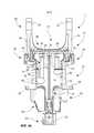
фиг. 1 - ротационное устройство, согласно изобретению, по в комплекте с лесозаготовительной машиной, в изометрической проекции;fig. 1 is a rotary device according to the invention, complete with a forestry machine, in isometric projection;
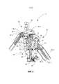
фиг. 2 - ротационное устройство, согласно изобретению, подвешенное к стреле и прикрепленное к лесозаготовительной головке, в изометрической проекции сзади;fig. 2 is a rotary device according to the invention suspended from the boom and attached to the harvesting head, in perspective view from the rear;
фиг. 3а - продольный разрез первого варианта выполнения структуры и ротационного устройства, согласно изобретению;fig. 3a is a longitudinal section of a first embodiment of a structure and a rotary device according to the invention;
фиг. 3b - продольный разрез под углом 900 относительно фиг. 3а первого варианта выполнения структуры и ротационного устройства, согласно изобретению;fig. 3b is a longitudinal section at 90° with respect to FIG. 3a of a first embodiment of a structure and a rotary device according to the invention;
фиг. 4а - продольный разрез второго варианта выполнения структуры и ротационного устройства, согласно изобретению;fig. 4a is a longitudinal section of a second embodiment of a structure and a rotary device according to the invention;
фиг. 4b - продольный разрез под углом 900 относительно фиг. 4а второго варианта выполнения структуры и ротационного устройства, согласно изобретению,fig. 4b is a longitudinal section at 90° with respect to FIG. 4a of a second embodiment of a structure and a rotary device according to the invention,
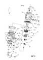
фиг. 5 - отделенное ротационное устройство, согласно изобретению, в изометрической проекции;fig. 5 is an isometric perspective view of a detached rotary device according to the invention;
фиг. 6 - ротационное устройство, согласно изобретению, на виде сбоку в том же направлении, что и на фиг. 3b и 4b;fig. 6 is a side view of the rotary device according to the invention in the same direction as in FIG. 3b and 4b;
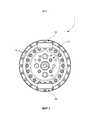
фиг. 7 - ротационное устройство, согласно изобретению, на виде сверху;fig. 7 is a top view of a rotary device according to the invention;
фиг. 8 - третий вариант выполнения ротационного устройства и структуры ротационного устройства, согласно изобретению, в разнесенной изометрической проекции;fig. 8 is an exploded perspective view of a third embodiment of the rotary device and the structure of the rotary device according to the invention;
фиг. 9 - продольный разрез в двух плоскостях четвертого варианта выполнения,fig. 9 is a longitudinal section in two planes of the fourth embodiment,
фиг. 10 - четвертый вариант выполнения ротационного устройства и структуры ротационного устройства, согласно изобретению, в разнесенной изометрической проекции.fig. 10 is an exploded perspective view of a fourth embodiment of the rotary device and the structure of the rotary device according to the invention.
Как показано на фиг. 1, ротационное устройство 1, согласно изобретению, подходит для использования предпочтительно в комплекте с лесозаготовительной машиной 100. Ротационное устройство может именоваться часто используемым в данной области техники термином ротатор. Обычно в лесозаготовительных машинах 100 имеется несколько рабочих стрел 102, из которых к последней стреле 2 прикреплено с возможностью поворота ротационное устройство 1. Как известно из уровня техники, поворот ротационного устройства 1 может обеспечиваться посредством использования двух поперечных шарнирных соединений в разных направлениях относительно друг друга, за счет чего ротационное устройство 1 всегда располагается вертикально независимо от высоты рабочих стрел 102. Ротационное устройство 1 может быть прикреплено к находящейся на головке 3 скобе 5 с возможностью беспрепятственного вращения вокруг оси вращения ротационного устройства 1 с помощью ротационного устройства 1. В соответствии с известным уровнем техники, рабочая среда, необходимая рабочим устройствам головки 3, проходит через ряд рабочих стрел 102 по шлангам от насоса рабочей среды 106 лесозаготовительной машины 100, работающего от двигателя 104 лесозаготовительной машины 100 для создания давления. В соответствии с фиг. 1, ротационное устройство 1 по изобретению пропускает поток рабочей среды, проходящей через ряд рабочих стрел 102, через ротационное устройство 1 к головке 3. Соответственно, электрическое управление головкой 3 также идет от лесозаготовительной машины 100 с помощью ряда рабочих стрел 102 через ротационное устройство 1 к головке 3.As shown in FIG. 1, a
Как показано на фиг. 2, при использовании ротационного устройства 1, согласно изобретению, поток рабочей среды из ротационного устройства 1 проходит по магистралям 60.1-60.3 к клапанному блоку 4 головки 3, откуда далее поток направляется к рабочим механизмам головки 3 и поворотному устройству 24, предназначенному для вращения устройства 1. Рабочими механизмами головок могут быть, например, режущие цилиндры, двигатели подачи, подающие ролики и обдирочные лапы цилиндров. Ротационное устройство по изобретению предпочтительно предназначено для использования в комплекте с лесозаготовительной машиной, в которой рабочей средой является гидравлическая жидкость, но изобретение подходит также для использования с пневматическими потоками рабочей среды. В соответствии с этим, следует понимать, что вместо лесозаготовительной машины ротационное устройство и структура ротационного устройства по изобретению подходят также для использования, например, с экскаваторами и другими рабочими машинами, оборудованными комплектом стрел, в которых рабочий механизм, если имеются рабочие механизмы, такой как ковш или черпак, или что-то подобное, требующее рабочей среды, прикреплен к ряду рабочих стрел.As shown in FIG. 2, when using the
Пропуск рабочей среды от стрелы 2 к ротационному устройству 1, как показано на фиг. 2, может осуществляться различными путями. Соединение магистралей рабочей среды при соединении с крышкой 88 ротационного устройства 1, показанное на фиг. 7, может проходить параллельно оси вращения ротационного устройства и быть под прямым углом к второй оси вращения, поворачивающей ротационное устройство 1 к стреле. Другими словами, соединение соединительных магистралей с ротатором ориентировано в соответствии с фиг. 2 вверх, если рассматривать соединение относительно его продольного направления. Магистрали потока рабочей среды, выходящей из стрелы 2, т.е. в данном случае из конца стрелы, предпочтительно проходят через поворотное соединение между стрелой 2 и ротационным устройством 1 и через его ось вращения. В другом случае, в продольном направлении соединения потоков рабочей среды могут быть под углом 5-850The passage of the working medium from the
относительно плоскости крышки ротационного устройства так, что, другими словами, соединение магистралей располагается под пологим углом к крышке, наиболее предпочтительно, чтобы продольное направление соединения пересекало бы воображаемую ось вращения нижнего соединения вращающихся соединений между ротационным устройством и стрелой. Более того, в другом случае, соединения магистралей потоков рабочей среды могут быть сформированы на стороне ротационного устройства, соседнего со стрелой, и магистрали могут проходить в направлении оси вращения вращающегося соединения на стороне головки, проходящей через это вращающееся соединение, т.е. через первое вращающееся соединение, но огибая конец второго вращающегося соединения, и оттуда к соединениям, закрепленным на стороне лесозаготовительной машины на стороне ротационного устройства. Сказанное выше только иллюстрирует примерные пути прохождения потока рабочей среды к ротационному устройству.relative to the plane of the cover of the rotary device so that, in other words, the line connection is at a gentle angle to the cover, most preferably, the longitudinal direction of the connection intersects the imaginary axis of rotation of the lower connection of the rotating connections between the rotary device and the boom. Moreover, in another case, the fluid line connections may be formed on the side of the rotary device adjacent to the boom, and the lines may extend in the direction of the axis of rotation of the rotary joint on the side of the head passing through the rotary joint, i.e. through the first rotating joint, but skirting the end of the second rotating joint, and from there to the joints fixed on the harvester side on the rotating device side. The above only illustrates exemplary paths for the flow of the working fluid to the rotary device.
На фиг. 3а показан разрез первого примера выполнения ротационного устройства 1 и структуры 10 ротационного устройства по изобретению. Ротационное устройство 1 по изобретению включает ротационное устройство и прикрепленное к нему поворотное устройство 24, а также электрический проводник 96 адаптера 48, показанные на фиг. 9. Адаптер 48 предпочтительно прикреплен к нижней поверхности 94 поворотного устройства 24 (как показано на фиг. 3b и 4b). Поворотное устройство 24 частично предпочтительно присоединено к нижней поверхности 92 второй наружной корпусной части 14. В этой связи, нижняя поверхность представляет собой с учетом ориентации подвески ротационного устройства противоположную средствам подвески сторону структуры ротационного устройства. Структура (конструкция) 10 ротационного устройства 1 включает в качестве принципиальных компонентов первую внутреннюю корпусную часть 12, вторую наружную корпусную часть 14, опорное средство 20, соединительное средство 22, осевой канал 16, имеющий два конца 16.1 и 16.2, первые каналы 26, вторые каналы 30 и соединения 28. Конец 16.1 включает держатель электрического проводника (не показан). Первая внутренняя корпусная часть 12 является цилиндрической, через нее проходит осевой канал 16, предназначенный для электрических проводников, и первый канал 26 для прохождения рабочей среды. Осевой канал 16 образует соединение на том конце цилиндрической первой внутренней корпусной части, который лежит противоположно поворотному устройству 24, соединенному со структурой ротационного устройства 1, и снаружи поворотного устройства 24. Другой конец 16.2 осевого канала 16 является концом, который находится на том конце первой внутренней корпусной части 12, к которому должно прикрепляться поворотное устройство.FIG. 3a shows a section through a first exemplary embodiment of the
В примерах реализации изобретения на фиг. 3a-4b, имеется три первых канала 26 для пропускания трех отдельных потоков рабочей среды через первую внутреннюю корпусную часть 12. Первые каналы 26 предпочтительно являются осевыми относительно первой внутренней корпусной части 12, т.е. параллельны осевому каналу 16, и каждый первый канал 26 имеет два конца. Первый из каждых концов первого канала 26 образует соединение на конце первой цилиндрической внутренней корпусной части 12 противоположно поворотному устройству 24, для присоединения к структуре ротационного устройства 1. Другой конец, в свою очередь, образует соединение радиально стороне первой внутренней корпусной части. Первые каналы 26 могут также быть под небольшим углом относительно продольного направления первой внутренней корпусной части 12, при этом вторые концы первых каналов 26 будут образовывать прямое присоединение к сторонам первой внутренней корпусной части. На фиг. 3а, левосторонний первый канал 26 относительно осевого канала 16 является прямой напорной магистралью сжатой среды, а правосторонний первый канал 26 является обратной магистралью. Первый канал 26 и осевой канал 16 имеют диаметр 2-50 мм и предпочтительно имеют круглое сечение. Каналы 26 и 16 предпочтительно имеют 15-30 мм в диаметре для обеспечения оптимального объема для потока.In the exemplary embodiments of FIG. 3a-4b, there are three
В примерах реализации изобретения на фиг. 1-9 первая внутренняя корпусная часть 12 предназначена для подвешивания ротационного устройства 1 на стреле 2 лесозаготовительной машины с помощью ее подвесного средства 90. В данном примере ушки 54 в качестве части подвесного средства 90 сформированы на первой внутренней корпусной части 12, в данных ушках имеются отверстия 50 для поворота ротационного устройства 1 относительно стрелы 2 лесозаготовительной машины.In the exemplary embodiments of FIG. 1-9, the first
Вторая наружная корпусная часть 14 частично предпочтительно сформирована в виде рукава, который в радиальном направлении размещается на поверхности первой внутренней корпусной части 12. Между первой внутренней корпусной частью 12 и второй наружной корпусной частью 14 имеется опорное средство 20, которое обеспечивают взаимный поворот первой внутренней корпусной части 12 и второй наружной корпусной части 14 относительно друг друга. Если ротационное устройство 1 подвешено, как показано на фиг. 1-7, т.е. от первой внутренней корпусной части 12 к стреле 2, то когда головка 4 поворачивается, первая внутренняя корпусная часть 12 остается на месте, а вторая наружная корпусная часть 14 поворачивается по поверхности первой внутренней корпусной части 12, примыкающей к головке 3. В качестве опорного средства 20 предпочтительно использовать кольцевые подшипники 40, которые имеют то преимущество, что могут легко заменяться, и доступны от многих производителей. Опорное средство предпочтительно содержит подшипники и зубцы, установленные так, чтобы обеспечивать вращение второй наружной корпусной части 14 относительно первой внутренней корпусной части 12. Как указывалось ранее, опорное средство 20 размещено так, чтобы нести осевую и радиальную нагрузку. Осевая нагрузка создается головкой 3 и передается в основном как вертикальная нагрузка через поворотное устройство 24 ко второй наружной корпусной части 14 и через нее к опорным средствам 20. С другой стороны, горизонтальные перемещения головки 3 вызывают усилия, которые передаются через вторую наружную корпусную часть 14, создавая радиальную нагрузку на опорные средства 20.The second
Вторая наружная корпусная часть 14 также включает ее радиальные соединения 28, которые предназначены для пропуска рабочей среды от первой внутренней корпусной части 12 через вторую наружную корпусную часть 14. Предпочтительно, обеспечивается столько соединений 28, сколько имеется первых каналов 26. Для того чтобы обеспечивались соединения при любом положении первой внутренней корпусной части 12 и второй наружной корпусной части 14 относительно друг друга, вторые каналы образованы во внешней поверхности первой внутренней корпусной части 12 или во внутренней поверхности второй наружной корпусной части 14, или в обеих. В примерах реализации изобретения, согласно фиг. 3a-4b, второй канал 30 образован во внешней поверхности 32 первой внутренней корпусной части 12. Внутренняя поверхность второй наружной корпусной части 14 обозначена позицией 34. Каждый второй канал 30 предпочтительно является круглым, что обеспечивает пропуск потока рабочей среды независимо от взаимного расположения первой внутренней корпусной части 12 и второй наружной корпусной части 14. Другими словами, каждый второй канал представляет собой непрерывное кольцевое радиальное углубление в первой внутренней корпусной части 12, во второй наружной корпусной части 14 или в обеих. На фиг. 3а - 4b показано, что предпочтительно иметь столько вторых каналов 30, сколько имеется первых каналов 26 и соединений 28. При осуществлении вращательного перемещения предпочтительно предусмотреть уплотнения для предотвращения подтекания или утечки рабочей среды из второго канала между первой внутренней корпусной частью и второй наружной корпусной частью. В примерах реализации изобретения на фиг. 3a-4b уплотнения 70 для вращательного перемещения сформированы в первой внутренней корпусной части 12.The second
Соединительное средство 22 предназначено для прикрепления поворотного устройства 24 прямого потока сжатой рабочей среды к структуре 10 коаксиально относительно оси вращения первой внутренней корпусной части 12 и второй наружной корпусной части 14 для передачи момента вращения. В этом соединении термин прямой поток рабочей среды означает, что усилие передается непосредственно к первой внутренней корпусной части 12, например, с помощью полого вала 36. Поворотное устройство 24 вместе со структурой 10 образует ротационное устройство 1, согласно изобретению. Соединительное средство 22 предпочтительно предназначено для соединения указанного поворотного устройства 24 со второй наружной корпусной частью 14 так, чтобы поворотное устройство 24 постоянно прилегало ко второй наружной корпусной части 14.The connecting means 22 is intended for attaching the
Структура 10 предпочтительно включает полый вал 36, у которого сформирован передающий усилие элемент 76. Как показано на фиг. 3а и 3b, полый вал 36 может представлять собой отдельный вал, который проходит через первую внутреннюю корпусную часть 12 внутреннего тела и в котором образован упомянутый осевой канал 16. Как показано на фиг. 3а и 3b, полый вал 36 может быть присоединен к первой внутренней корпусной части 12 с использованием соединения с геометрическим замыканием, например, с помощью рифления 74 (более подробно показано на фиг. 8) для того, чтобы передавать момент вращения поворотного устройства 24 непосредственно первой внутренней корпусной части 12, вращая таким образом вторую наружную корпусную часть 14 вокруг первой внутренней корпусной части 12. Также, однако, возможно присоединять полый вал 36 к первой внутренней корпусной части 12 посредством фрикционного соединения, например, термического соединения. Длина полого вала 36 должна быть такой, чтобы он проходил по первой внутренней корпусной части 12 и по меньшей мере частично по поворотному устройству 24, соединенному со структурой 10. Сформированный в полом валу 36 передающий усилие элемент 76 является предпочтительно так же рифленым и передает момент вращения между поворотным устройством 24 и первой внутренней корпусной частью 12.The
Когда ротационное устройство 1 вращается, первая внутренняя корпусная часть 12 и соединенный с ней полый вал 36 остаются неподвижными, а поворотное устройство 24 и соединенная с ней вторая наружная корпусная часть 14 вращаются. Второе соединительное средство 78 сформировано в торце поворотного устройства 24 полого вала 36, благодаря чему обеспечивается соединение адаптера 48 с концом полого вала 36. Как показано на фиг. 4а и 4b, полый вал 36 может быть сформирован в виде фиксированной части первой внутренней корпусной части 12 так, что полый вал 36 выступает из первой внутренней корпусной части 12, в центре которого проходит канал 16 электрических проводников.When the
Осевой канал 16 обеспечивает прохождение выходящих из стрелы электрических проводников через ротационное устройство 1 к концу 16.2 поворотного устройства 24 по меньшей мере в том случае, когда конец 16.2 коаксиален с первой внутренней корпусной частью 12 и через поворотное устройство 24 соединен с ротационным устройством. Вследствие того, что электрические проводники не должны препятствовать полному повороту ротационного устройства, электрические проводники предпочтительно должны быть соединены с адаптером 48 ротационного устройства. Адаптер 48 полностью поворачивается таким образом, что электрические проводники могут быть присоединены с возможностью поворота к верхней части адаптера, а электрический сигнал передается через адаптер к вращаемому в его нижней части соединителю 64, к которому прикреплены проходящие к головке электрические проводники. Адаптер может быть любым коммерчески доступным поворотным адаптером. Предпочтительно электрические проводники, проходящие через ротационное устройство, согласно изобретению, представляют собой шину передачи данных, предпочтительно шину САN или ArcNet, и используется адаптер 48 той же фирмы САN или, соответственно, фирмы ArcNet. С помощью шин САN или ArcNet осуществляется электрическое управление функциями операционных механизмов, измерительных датчиков и клапанного распределения. Могут использоваться более одного электрических проводников. Для адаптера 48 ротационное устройство 1 может также включать защитный кожух 52, который может быть прикреплен к поворотному устройству 24. Размещение адаптера под поворотным устройством 24 делает конструкцию менее сложной, чем описано в ротационных устройствах, известных из уровня техники.The
Используемое в ротационном устройстве по изобретению поворотное устройство предпочтительно представляет собой поворотное устройство, расположенное коаксиально вокруг полого вала так, что осевой канал 16, параллельный оси вращения ротационного устройства, проходит через всю структуру и по меньшей мере частично через поворотное устройство, прикрепленное к структуре. Ротационное устройство может быть выполнено так, что не увеличиваются его радиальные размеры. Поворотное устройство 24, используемое в ротационном устройстве, предпочтительно является гидравлическим радиальным поршневым двигателем 42. Преимуществом радиального поршневого двигателя является его удобство и долговременность в использовании, поскольку в нем уплотнение осуществляется с помощью вращательного движения подшипников. В качестве альтернативы, поворотное устройство может также быть лопастным двигателем, который может быть установлен вокруг полого вала для обеспечения прямого привода.The pivot device used in the rotary device according to the invention is preferably a pivot device arranged coaxially around the hollow shaft such that an
В примерах реализации изобретения согласно фиг. 3a-4b, структура 10 ротатора 1 по изобретению может также включать дополнительный канал 80, образованный дополнительным первым каналом 26, вторым каналом 30 и соединением 28 для направления жидкости через ротационное устройство 1. Жидкостью может быть, например, агент для обработки пней или смазывающий агент, например смазывающее масло или консистентная смазка. Обычно используемая в качестве агента мочевина применяется в лесозаготовительных машинах для обработки пней при рубке дерева. При рубке дерева пень от дерева остается открытым, легко подвергаемым паразитическим инфекциям, например, красный грибок может легко поселиться на открытой поверхности древесины. Красный грибок может легко распространиться от зараженных пней на другие здоровые деревья и в результате уничтожить лесные запасы.In the exemplary embodiments of FIGS. 3a-4b, the
В примерах реализации изобретения на фиг. 3a-3b, в которых полый вал 36 является отдельной частью первой внутренней корпусной части 12, один из первых каналов 26 может быть образован коаксиально полому валу 36 между полым валом 36 и первой внутренней корпусной частью 12. Другими словами, между полым валом 36 и первой внутренней корпусной частью 12 остается свободное пространство, через которое может осуществлять дренаж рабочей среды и от поворотного устройства 24, и от головки через ротационное устройство 1. В этом случае удается избежать использования одного дополнительного канала и двух уплотнений для вращательного движения.In the exemplary embodiments of FIG. 3a-3b, in which the
На фиг. 5 показано ротационное устройство 1, согласно изобретению, отдельно от лесозаготовительной машины. Здесь магистрали рабочей среды 60.1, 60.2 и 60.3, проходящие к головке, присоединены соединителями 28. Среди них магистраль 60.1 является напорной магистралью рабочей среды, магистраль 60.2 - обратной магистралью, а 60.3 - дренажной магистралью. Соединители 62, с помощью которых рабочая среда проходит от головки к поворотному устройству 24, показаны под магистралями 60.1, 60.2 и 60.3. Позицией 46 обозначены отверстия, с помощью которых ротационное устройство 1 прикрепляется болтами к скобе 5 головки 3, как показано на фиг. 1 и 2. На фиг.5 электрические проводники обозначены позицией 56. Шланг 82 является магистралью для агента превентивной обработки пней, представляющего собой дополнительную жидкость.FIG. 5 shows a
На фиг. 6 более подробно показаны соединители 28, к которым крепятся магистрали рабочей среды 60.1, 60.2 и 60.3 (см. фиг. 5). Показаны также соединители 62 поворотного устройства 24, к которым присоединяются магистрали 62.1-62.3 из фиг. 2, при этом магистрали рабочей среды 62.1 и 62.2 являются, соответственно, напорной и обратной магистралями, а средняя магистраль рабочей среды 62.3 является дренажной магистралью. Позицией 86 обозначен соединитель магистрали агента превентивной обработки.FIG. 6 shows in more detail the
На фиг. 7 показано на виде сверху ротационное устройство 1, согласно изобретению. В этом варианте выполнения изобретения в крышке 88 ротационного устройства 1 расположены соединители для первых каналов 26 и осевого канала 16. Здесь первый канал 26 меньшего диаметра с правой стороны от осевого канала 16 является магистралью превентивного агента. В свою очередь, соединитель под осевым каналом 16 предназначен для напорного потока рабочей среды, верхний соединитель - для обратной магистрали, а соединитель с левой стороны - для дренажной магистрали. Однако следует иметь в виду, что другие первые каналы могут использоваться для других целей, т.е. напорная магистраль, обратная магистраль и дренажная магистраль могут быть размещены в другом порядке.FIG. 7 shows a top view of a
На фиг. 8 показано в разнесенной изометрической проекции ротационное устройство 1, согласно изобретению. В соответствии с фиг. 8, первая внутренняя корпусная часть 12 предпочтительно состоит из двух частей 12.1 и 12.2, из которых часть 12.1 включает первые каналы 26, а часть 12.2 - вторые каналы 30. В соответствии с фиг. 8, ротационное устройство 1 также включает крышку 88, которая может быть присоединена к первой внутренней корпусной части 12. В третьем варианте выполнения изобретения ротационного устройства 1 и структуры 10 ротационного устройства 1 по фиг. 8 продолжающие каналы выполнены в крышке 88 как продолжения первых каналов 26, которые поворачивают соединители для шлангов рабочей среды по существу на 900 относительно ориентации первых каналов. Таким образом, шланги выходят из крышки 88 ротационного устройства 1 сбоку в отличие от варианта выполнения изобретения на фиг. 1-7. В соответствии с фиг. 8, несколько частей прикреплены друг к другу с помощью болтов или другого крепежного средства так, что при необходимости ротационное устройство может быть легко демонтировано. На фиг. 8 части кольцевой опоры 40 обозначены позициями 40.1 и 40.2.FIG. 8 is an exploded perspective view of a
В отличие от вариантов выполнения изобретения, согласно фиг. 1-9, ротационное устройство по изобретению может быть выполнено так, что вторая наружная корпусная часть структуры ротационного устройства присоединена к ушкам, а через них, к стреле, при этом головка присоединена к первой внутренней корпусной части.In contrast to the embodiments of the invention, according to FIGS. 1-9, the rotary device according to the invention may be configured such that the second outer housing portion of the structure of the rotary device is connected to the lugs and, through them, to the boom, the head being connected to the first inner housing portion.
На фиг. 9 и 10 показан четвертый вариант выполнения структуры тела ротационного устройства по изобретению. Здесь, в отличие от фиг. 8, внутренняя корпусная часть 12 представляет собой единое целое и не разделена на две части 12.1 и 12.2, как это показано на фиг. 8. Расположение напорной магистрали 60.1, обратной магистрали 60.2 и дренажной магистрали 60.3 изменено на фиг. 9 по отношению к фиг. 8. В соответствии с фиг. 9, дренажная магистраль 60.3 сформирована между первой внутренней корпусной частью 12 и осевым каналом 16. На фиг. 9 показан входной держатель 16.3 кабеля и электрические проводники (кабели)96.FIG. 9 and 10 show a fourth embodiment of the body structure of the rotary device according to the invention. Here, in contrast to FIG. 8, the
Ротационное устройство и структура ротационного устройства, согласно изобретению, за исключением средства уплотнения, предпочтительно выполнены из стали или подобного материала, подходящего для данной цели. Осевая высота осевого канала ротационного устройства по изобретению может быть 300-800 мм, диаметр 200-400 мм, предпочтительно 250-350 мм. Вес ротационного устройства может быть 50-200 кг, предпочтительно 100-150 кг для получения оптимального соотношения мощность-вес. Используемые опоры могут быть известных конструкций, предпочтительно роликовыми подшипниками, например, игольчатым, шариковыми, роликовыми или коническими, или более предпочтительно кольцевыми подшипниками. С другой стороны могут использоваться подшипники скольжения, если они будут нести ту же нагрузку, что и кольцевые, и если будут выполнены из бронзы для подшипников, меди или каких-то полимеров.The rotary device and the structure of the rotary device according to the invention, with the exception of the sealing means, are preferably made of steel or a similar material suitable for this purpose. The axial height of the axial channel of the rotary device according to the invention may be 300-800 mm, diameter 200-400 mm, preferably 250-350 mm. The weight of the rotary device may be 50-200 kg, preferably 100-150 kg, for optimum power-to-weight ratio. The supports used can be of known designs, preferably roller bearings, for example needle, ball, roller or tapered, or more preferably annular bearings. On the other hand, sleeve bearings can be used if they carry the same load as ring bearings and if they are made of bronze for bearings, copper or some kind of polymers.
Вариации решений, показанных на фиг. 3а-3b, (не в соответствии с изобретением) могут быть такими, в которых ни центральный канал, ни адаптер, обеспечивающий вращение, не понадобятся вообще, поскольку требуемая электроэнергия будет вырабатываться в лесозаготовительной машине, передача данных к головке будет беспроводной непосредственно от подвесного устройства или напрямую от базовой машины. Возможно также перемещать адаптер, обеспечивающий вращение, к ротационному устройству, что, однако, представляется сложным, если будут использоваться стандартные компоненты.Variations of the solutions shown in FIG. 3a-3b, (not in accordance with the invention) may be such that neither a center channel nor an adapter for rotation is needed at all, since the required electrical power will be generated in the harvester, data transmission to the head will be wireless directly from the pendant or directly from the base machine. It is also possible to move the rotating adapter towards the rotating device, which however is difficult if standard components are to be used.
Claims (22)
Translated fromRussianApplications Claiming Priority (3)
| Application Number | Priority Date | Filing Date | Title |
|---|---|---|---|
| FI20165437 | 2016-05-25 | ||
| FI20165437AFI127285B (en) | 2016-05-25 | 2016-05-25 | Structure of the rotating device and the corresponding rotating device and forestry machine |
| PCT/FI2017/050397WO2017203107A1 (en) | 2016-05-25 | 2017-05-26 | Structure of a rotation device, and a corresponding rotation device, and a forest machine |
Publications (3)
| Publication Number | Publication Date |
|---|---|
| RU2018144353A RU2018144353A (en) | 2020-06-25 |
| RU2018144353A3 RU2018144353A3 (en) | 2020-06-26 |
| RU2738981C2true RU2738981C2 (en) | 2020-12-21 |
Family
ID=60412725
Family Applications (1)
| Application Number | Title | Priority Date | Filing Date |
|---|---|---|---|
| RU2018144353ARU2738981C2 (en) | 2016-05-25 | 2017-05-26 | Design of rotary device and corresponding rotary device, and logging machine |
Country Status (10)
| Country | Link |
|---|---|
| US (1) | US11365526B2 (en) |
| EP (1) | EP3464153B1 (en) |
| CN (1) | CN109195899B (en) |
| BR (1) | BR112018073998B1 (en) |
| CA (1) | CA3024769A1 (en) |
| DE (1) | DE202017007033U1 (en) |
| FI (3) | FI127285B (en) |
| RU (1) | RU2738981C2 (en) |
| SE (1) | SE543931C2 (en) |
| WO (1) | WO2017203107A1 (en) |
Families Citing this family (7)
| Publication number | Priority date | Publication date | Assignee | Title |
|---|---|---|---|---|
| JP7345197B2 (en)* | 2018-04-04 | 2023-09-15 | カレルボ ケトーネン ラウリ | Fully rotary rotating device |
| US20200080277A1 (en)* | 2018-09-10 | 2020-03-12 | Caterpillar Work Tools B.V. | Excavator split connector |
| CA3210858A1 (en)* | 2021-03-03 | 2022-09-09 | Jason MC NEIL | Material handler skip pan |
| DE202021106382U1 (en)* | 2021-11-23 | 2022-02-23 | Pister Kugelhähne GmbH | Tilt rotator for a working machine |
| WO2023121122A2 (en)* | 2021-12-24 | 2023-06-29 | 주식회사 경원테크 | Excavating apparatus |
| SE546161C2 (en)* | 2022-09-02 | 2024-06-11 | Rottne Ind Ab | Harvester head for forestry and a harvester using such head |
| US20240392539A1 (en)* | 2023-05-22 | 2024-11-28 | Cnh Industrial America Llc | Hydraulic fitting assembly for a construction vehicle |
Citations (6)
| Publication number | Priority date | Publication date | Assignee | Title |
|---|---|---|---|---|
| CN1104282A (en)* | 1992-07-27 | 1995-06-28 | 吉尔摩运输服务有限公司 | Coupling for heavy-duty machine |
| US5632625A (en)* | 1995-05-26 | 1997-05-27 | Apollo Machinery, Ltd. | Rotary electrical coupling with circumferential conductive elastomer brush |
| WO1999037136A1 (en)* | 1998-01-20 | 1999-07-29 | Rotobec Inc. | Continuous rotary link for multifunction head |
| CN2543238Y (en)* | 2002-06-13 | 2003-04-02 | 温州飞龙电器有限公司 | Improved industrial plug and connector thereof |
| EP2460758A1 (en)* | 2010-12-02 | 2012-06-06 | EPSILON Kran GmbH. | Hydraulic rotation drive |
| RU2515637C2 (en)* | 2008-12-16 | 2014-05-20 | Кейтерпиллар Инк. | Motors and devices for working of trees |
Family Cites Families (18)
| Publication number | Priority date | Publication date | Assignee | Title |
|---|---|---|---|---|
| US4009643A (en) | 1975-02-26 | 1977-03-01 | Heinz Thumm | Hydraulic motor for rotating the bucket of an excavating machine |
| DE2838346C2 (en)* | 1978-09-02 | 1985-02-14 | Fa. Heinz Thumm, 7012 Fellbach | Rotating device for an excavator grab or the like. |
| FR2501823B1 (en)* | 1981-03-13 | 1986-09-12 | Ardennes Equipements | DEVICE FOR FIXING AND SUPPLYING HYDRAULIC HANDLING EQUIPMENT TO A LIFTING MACHINE |
| DE3113263C2 (en)* | 1981-04-02 | 1994-04-28 | Thumm Heinz Oelhydraulik | Device for rotating suspended loads |
| US5908060A (en)* | 1998-01-28 | 1999-06-01 | Prenbec Inc. | Tree processing machine |
| JP4678705B2 (en)* | 2000-11-29 | 2011-04-27 | 株式会社小松製作所 | Hydraulically driven work machine |
| CA2353239A1 (en)* | 2001-07-18 | 2003-01-18 | Rotobec Inc. | Motor-driven, boom-mounted rotor assembly |
| SE520498E8 (en) | 2001-11-26 | 2015-10-20 | Komatsu Forest Ab | Device for hanging a rotary working tool |
| SE524754C2 (en)* | 2002-01-21 | 2004-09-28 | Indexator Ab | Rotator with rotary position sensor and method for rotary position determination in a rotator |
| CN2548986Y (en)* | 2002-04-30 | 2003-05-07 | 丁晓东 | Large capacity multi-claw sealed frequency converting hydraulic bucket grab |
| US7735530B1 (en) | 2006-10-20 | 2010-06-15 | Puma, Llc | Rotary dangle head having continuous rotation |
| KR20090110466A (en)* | 2008-04-18 | 2009-10-22 | 이수규 | Hydraulic rotating device with improved fixing unit |
| ATE513125T1 (en) | 2008-08-29 | 2011-07-15 | Baltrotors Sia | PISTON LATHE |
| EP2234213A1 (en)* | 2009-03-26 | 2010-09-29 | Mbd S.R.L. | Joint for transmitting and distributing electric power, electric signals, or several pressurised fluids, particularly adapted for machines for calibrating and smoothing stone materials |
| SE1100099A1 (en)* | 2010-11-15 | 2012-05-16 | Indexator Ab | Procedure and apparatus for a working arm |
| FI123051B (en) | 2011-01-13 | 2012-10-15 | Matti Niemelae | Adapter for attachment to boom attachment and rotator and similar arrangement |
| SE537562C2 (en) | 2011-03-26 | 2015-06-16 | Indexator Rotator Sys Ab | Device at a rotator |
| WO2014133399A1 (en) | 2013-02-28 | 2014-09-04 | Waratah Nz Limited | A rotator for connecting a timber-working implement to a forestry work machine |
- 2016
- 2016-05-25FIFI20165437Apatent/FI127285B/enactiveIP Right Review Request
- 2017
- 2017-05-26CNCN201780032018.1Apatent/CN109195899B/enactiveActive
- 2017-05-26CACA3024769Apatent/CA3024769A1/enactivePending
- 2017-05-26WOPCT/FI2017/050397patent/WO2017203107A1/ennot_activeCeased
- 2017-05-26BRBR112018073998-7Apatent/BR112018073998B1/enactiveIP Right Grant
- 2017-05-26EPEP17802263.8Apatent/EP3464153B1/enactiveActive
- 2017-05-26RURU2018144353Apatent/RU2738981C2/enactive
- 2017-05-26DEDE202017007033.2Upatent/DE202017007033U1/enactiveActive
- 2017-05-26FIFI20186119Apatent/FI131639B1/enactive
- 2017-05-26SESE1851651Apatent/SE543931C2/enunknown
- 2017-05-26FIFIU20184217Upatent/FI12321U1/enactiveIP Right Grant
- 2018
- 2018-11-20USUS16/197,311patent/US11365526B2/enactiveActive
Patent Citations (6)
| Publication number | Priority date | Publication date | Assignee | Title |
|---|---|---|---|---|
| CN1104282A (en)* | 1992-07-27 | 1995-06-28 | 吉尔摩运输服务有限公司 | Coupling for heavy-duty machine |
| US5632625A (en)* | 1995-05-26 | 1997-05-27 | Apollo Machinery, Ltd. | Rotary electrical coupling with circumferential conductive elastomer brush |
| WO1999037136A1 (en)* | 1998-01-20 | 1999-07-29 | Rotobec Inc. | Continuous rotary link for multifunction head |
| CN2543238Y (en)* | 2002-06-13 | 2003-04-02 | 温州飞龙电器有限公司 | Improved industrial plug and connector thereof |
| RU2515637C2 (en)* | 2008-12-16 | 2014-05-20 | Кейтерпиллар Инк. | Motors and devices for working of trees |
| EP2460758A1 (en)* | 2010-12-02 | 2012-06-06 | EPSILON Kran GmbH. | Hydraulic rotation drive |
Also Published As
| Publication number | Publication date |
|---|---|
| WO2017203107A1 (en) | 2017-11-30 |
| RU2018144353A (en) | 2020-06-25 |
| BR112018073998B1 (en) | 2023-01-31 |
| US20190119885A1 (en) | 2019-04-25 |
| EP3464153A4 (en) | 2020-06-03 |
| CA3024769A1 (en) | 2017-11-30 |
| FI127285B (en) | 2018-03-15 |
| BR112018073998A2 (en) | 2019-02-26 |
| EP3464153B1 (en) | 2021-09-22 |
| CN109195899A (en) | 2019-01-11 |
| SE1851651A1 (en) | 2018-12-21 |
| FI12321U1 (en) | 2019-03-15 |
| FI131639B1 (en) | 2025-08-18 |
| CN109195899B (en) | 2020-11-03 |
| SE543931C2 (en) | 2021-09-28 |
| FI20186119A1 (en) | 2018-12-20 |
| DE202017007033U1 (en) | 2019-03-25 |
| FI20165437A7 (en) | 2017-11-26 |
| RU2018144353A3 (en) | 2020-06-26 |
| EP3464153A1 (en) | 2019-04-10 |
| US11365526B2 (en) | 2022-06-21 |
Similar Documents
| Publication | Publication Date | Title |
|---|---|---|
| RU2738981C2 (en) | Design of rotary device and corresponding rotary device, and logging machine | |
| EP1448471B1 (en) | Device for mounting of a turnable implement | |
| KR101024512B1 (en) | Crane arm with fixture for work carryout | |
| US8074681B2 (en) | Swivel and rotator mechanism for fluid controlled machines | |
| US7735530B1 (en) | Rotary dangle head having continuous rotation | |
| CA3027844C (en) | Hose guiding device for a crane tool | |
| US8721248B2 (en) | Rotator | |
| EP3640514B1 (en) | Hydraulic joint and hydraulic boom crane assembly with a hydraulic joint | |
| EP2998609A1 (en) | Hydraulically operated pivotal joint and swing damping device | |
| RU2735391C2 (en) | Rotary device | |
| EP4132876A1 (en) | Rotator for a tool | |
| AU2013204317A1 (en) | A timber-working head and drive wheel arm |