RU2737627C2 - Device for conducting a medical procedure in a fluid medium transfer vessel (versions) - Google Patents
Device for conducting a medical procedure in a fluid medium transfer vessel (versions)Download PDFInfo
- Publication number
- RU2737627C2 RU2737627C2RU2018134785ARU2018134785ARU2737627C2RU 2737627 C2RU2737627 C2RU 2737627C2RU 2018134785 ARU2018134785 ARU 2018134785ARU 2018134785 ARU2018134785 ARU 2018134785ARU 2737627 C2RU2737627 C2RU 2737627C2
- Authority
- RU
- Russia
- Prior art keywords
- balloon
- valve
- fluid flow
- passage
- vessel
- Prior art date
Links
- 239000012530fluidSubstances0.000titleclaimsabstractdescription71
- 238000000034methodMethods0.000titleclaimsabstractdescription29
- 238000012546transferMethods0.000titleabstractdescription6
- 230000010412perfusionEffects0.000claimsabstractdescription31
- 239000000463materialSubstances0.000claimsdescription28
- 230000000903blocking effectEffects0.000abstractdescription4
- 230000000694effectsEffects0.000abstractdescription3
- 230000006835compressionEffects0.000abstractdescription2
- 238000007906compressionMethods0.000abstractdescription2
- 238000004519manufacturing processMethods0.000abstractdescription2
- 239000000126substanceSubstances0.000abstract1
- 210000003739neckAnatomy0.000description15
- 210000001765aortic valveAnatomy0.000description3
- 238000013158balloon valvuloplastyMethods0.000description3
- 230000017531blood circulationEffects0.000description3
- 239000008280bloodSubstances0.000description2
- 210000004369bloodAnatomy0.000description2
- 230000001276controlling effectEffects0.000description2
- 238000013461designMethods0.000description2
- 238000005516engineering processMethods0.000description2
- 239000000835fiberSubstances0.000description2
- 241000894007speciesSpecies0.000description2
- 241000251468ActinopterygiiSpecies0.000description1
- 238000013459approachMethods0.000description1
- 238000000429assemblyMethods0.000description1
- 230000000712assemblyEffects0.000description1
- 238000005452bendingMethods0.000description1
- 230000015572biosynthetic processEffects0.000description1
- 230000008081blood perfusionEffects0.000description1
- 230000004087circulationEffects0.000description1
- 238000004891communicationMethods0.000description1
- 238000010276constructionMethods0.000description1
- 210000002816gillAnatomy0.000description1
- 210000003709heart valveAnatomy0.000description1
- 238000002513implantationMethods0.000description1
- 230000014759maintenance of locationEffects0.000description1
- 238000012986modificationMethods0.000description1
- 230000004048modificationEffects0.000description1
- 230000002093peripheral effectEffects0.000description1
- 230000001105regulatory effectEffects0.000description1
- 230000002966stenotic effectEffects0.000description1
- 239000010409thin filmSubstances0.000description1
- 210000000591tricuspid valveAnatomy0.000description1
- 230000002792vascularEffects0.000description1
Images


Classifications
- A—HUMAN NECESSITIES
- A61—MEDICAL OR VETERINARY SCIENCE; HYGIENE
- A61M—DEVICES FOR INTRODUCING MEDIA INTO, OR ONTO, THE BODY; DEVICES FOR TRANSDUCING BODY MEDIA OR FOR TAKING MEDIA FROM THE BODY; DEVICES FOR PRODUCING OR ENDING SLEEP OR STUPOR
- A61M25/00—Catheters; Hollow probes
- A61M25/10—Balloon catheters
- A61M25/1018—Balloon inflating or inflation-control devices
- A61M25/10184—Means for controlling or monitoring inflation or deflation
- A61M25/10185—Valves
- A—HUMAN NECESSITIES
- A61—MEDICAL OR VETERINARY SCIENCE; HYGIENE
- A61M—DEVICES FOR INTRODUCING MEDIA INTO, OR ONTO, THE BODY; DEVICES FOR TRANSDUCING BODY MEDIA OR FOR TAKING MEDIA FROM THE BODY; DEVICES FOR PRODUCING OR ENDING SLEEP OR STUPOR
- A61M25/00—Catheters; Hollow probes
- A61M25/10—Balloon catheters
- A61M25/1002—Balloon catheters characterised by balloon shape
- A—HUMAN NECESSITIES
- A61—MEDICAL OR VETERINARY SCIENCE; HYGIENE
- A61M—DEVICES FOR INTRODUCING MEDIA INTO, OR ONTO, THE BODY; DEVICES FOR TRANSDUCING BODY MEDIA OR FOR TAKING MEDIA FROM THE BODY; DEVICES FOR PRODUCING OR ENDING SLEEP OR STUPOR
- A61M25/00—Catheters; Hollow probes
- A61M25/10—Balloon catheters
- A61M25/104—Balloon catheters used for angioplasty
- A—HUMAN NECESSITIES
- A61—MEDICAL OR VETERINARY SCIENCE; HYGIENE
- A61M—DEVICES FOR INTRODUCING MEDIA INTO, OR ONTO, THE BODY; DEVICES FOR TRANSDUCING BODY MEDIA OR FOR TAKING MEDIA FROM THE BODY; DEVICES FOR PRODUCING OR ENDING SLEEP OR STUPOR
- A61M29/00—Dilators with or without means for introducing media, e.g. remedies
- A61M29/02—Dilators made of swellable material
- A—HUMAN NECESSITIES
- A61—MEDICAL OR VETERINARY SCIENCE; HYGIENE
- A61M—DEVICES FOR INTRODUCING MEDIA INTO, OR ONTO, THE BODY; DEVICES FOR TRANSDUCING BODY MEDIA OR FOR TAKING MEDIA FROM THE BODY; DEVICES FOR PRODUCING OR ENDING SLEEP OR STUPOR
- A61M25/00—Catheters; Hollow probes
- A61M25/10—Balloon catheters
- A61M25/1011—Multiple balloon catheters
- A61M2025/1013—Multiple balloon catheters with concentrically mounted balloons, e.g. being independently inflatable
- A—HUMAN NECESSITIES
- A61—MEDICAL OR VETERINARY SCIENCE; HYGIENE
- A61M—DEVICES FOR INTRODUCING MEDIA INTO, OR ONTO, THE BODY; DEVICES FOR TRANSDUCING BODY MEDIA OR FOR TAKING MEDIA FROM THE BODY; DEVICES FOR PRODUCING OR ENDING SLEEP OR STUPOR
- A61M25/00—Catheters; Hollow probes
- A61M25/10—Balloon catheters
- A61M2025/1043—Balloon catheters with special features or adapted for special applications
- A61M2025/1081—Balloon catheters with special features or adapted for special applications having sheaths or the like for covering the balloon but not forming a permanent part of the balloon, e.g. retractable, dissolvable or tearable sheaths
- A—HUMAN NECESSITIES
- A61—MEDICAL OR VETERINARY SCIENCE; HYGIENE
- A61M—DEVICES FOR INTRODUCING MEDIA INTO, OR ONTO, THE BODY; DEVICES FOR TRANSDUCING BODY MEDIA OR FOR TAKING MEDIA FROM THE BODY; DEVICES FOR PRODUCING OR ENDING SLEEP OR STUPOR
- A61M25/00—Catheters; Hollow probes
- A61M25/10—Balloon catheters
- A61M2025/1043—Balloon catheters with special features or adapted for special applications
- A61M2025/1097—Balloon catheters with special features or adapted for special applications with perfusion means for enabling blood circulation only while the balloon is in an inflated state, e.g. temporary by-pass within balloon
- A—HUMAN NECESSITIES
- A61—MEDICAL OR VETERINARY SCIENCE; HYGIENE
- A61M—DEVICES FOR INTRODUCING MEDIA INTO, OR ONTO, THE BODY; DEVICES FOR TRANSDUCING BODY MEDIA OR FOR TAKING MEDIA FROM THE BODY; DEVICES FOR PRODUCING OR ENDING SLEEP OR STUPOR
- A61M2210/00—Anatomical parts of the body
- A61M2210/12—Blood circulatory system
- A61M2210/125—Heart
Landscapes
- Health & Medical Sciences (AREA)
- Life Sciences & Earth Sciences (AREA)
- Heart & Thoracic Surgery (AREA)
- Public Health (AREA)
- Animal Behavior & Ethology (AREA)
- Veterinary Medicine (AREA)
- Engineering & Computer Science (AREA)
- Anesthesiology (AREA)
- Biomedical Technology (AREA)
- Hematology (AREA)
- General Health & Medical Sciences (AREA)
- Biophysics (AREA)
- Child & Adolescent Psychology (AREA)
- Pulmonology (AREA)
- Vascular Medicine (AREA)
- Media Introduction/Drainage Providing Device (AREA)
- Infusion, Injection, And Reservoir Apparatuses (AREA)
Abstract
Description
Translated fromRussianВКЛЮЧЕНИЕ В ОПИСАНИЕ ИЗОБРЕТЕНИЯ СВЕДЕНИЙ ПУТЕМ ССЫЛКИINCLUSION IN THE DESCRIPTION OF THE INVENTION BY REFERENCE
[0001]Все публикации и патентные заявки, упомянутые в данном описании, включены в настоящее описание путем ссылки в том же объеме, как если бы указывалось, что каждая отдельная публикация или патентная заявка конкретно и индивидуально включена в настоящий документ путем ссылки.[0001] All publications and patent applications mentioned in this description are incorporated into this description by reference in the same scope, as if it were indicated that each individual publication or patent application specifically and individually incorporated into this document by reference.
УРОВЕНЬ ТЕХНИКИLEVEL OF TECHNOLOGY
[0002]Расширяемые устройства, такие как баллоны, широко используются при проведении медицинских процедур. В случае баллона он вводится в тело, обычно на конце катетера, пока не достигнет зоны интереса. Создание в баллоне дополнительного давления заставляет баллон раздуваться. В одном варианте применения баллон создает пространство внутри тела, когда он раздут.[0002] Expandable devices such as balloons are widely used in medical procedures. In the case of a balloon, it is inserted into the body, usually at the end of the catheter, until it reaches the area of interest. Additional pressure in the balloon causes the balloon to inflate. In one application, the balloon creates space within the body when it is inflated.
[0003]Баллоны могут использоваться в клапанах, связанных с сердцем, в том числе в процессе проведения аортальной баллонной вальвулопластики (BAV) (как описано в работе Hara и др. ʺPercutaneous balloon aortic valvuloplasty revisited: time for a renaissance?ʺCirculation2007;115:e334-8) и транскатетерной имплантации аортального клапана (TAVI)). Для такой процедуры раздутый баллон может быть выполнен с возможностью обеспечения непрерывного кровотока, или перфузии. Однако, когда баллон раздут, клапан сердца неизбежно временно не способен функционировать. Это может приводить к нарушениям кровотока, в том числе образованию нежелательного обратного тока крови.[0003] Balloons can be used in valves associated with the heart, including during aortic balloon valvuloplasty (BAV) (as described in Hara et al. Percutaneous balloon aortic valvuloplasty revisited: time for a renaissance? AnceCirculation 2007; 115 : e334-8) and transcatheter aortic valve implantation (TAVI)). For such a procedure, the inflated balloon may be configured to provide continuous blood flow, or perfusion. However, when the balloon is inflated, the heart valve is inevitably temporarily unable to function. This can lead to disturbances in blood flow, including the formation of unwanted backflow of blood.
[0004]Таким образом, желательно предложить перфузионный баллон, который может использоваться для регулирования потока текучей среды в процессе проведения процедуры, особенно при использовании в связи с процедурой, при которой клапан не способен функционировать в результате проведения этой процедуры или по иной причине.[0004] Thus, it is desirable to provide a perfusion balloon that can be used to regulate fluid flow during a procedure, especially when used in conjunction with a procedure in which the valve is unable to function as a result of the procedure or otherwise.
СУЩНОСТЬ РАСКРЫТИЯESSENCE OF DISCLOSURE
[0005]Технический эффект раскрытых вариантов осуществления может содержать достижение клапанной подачи, являющейся внешней по отношению к перфузионному баллону, которая создает усиленный поток текучей среды в процессе открытия клапана, повышенную блокировку потока в процессе закрытия клапана и/или создает более простой способ изготовления баллона (особенно в случае, когда он включает в себя неподатливую оболочку поверх баллона). В одном варианте осуществления может использоваться одиночный клапан для регулировки потока через весь проход, обеспечивая возможность перфузии, например, путем одновременного блокирования и разблокирования множества входов в проход.[0005] The technical effect of the disclosed embodiments may comprise achieving a valve delivery external to the perfusion balloon that creates increased fluid flow during valve opening, increased flow blockage during valve closure, and / or provides a simpler balloon manufacturing process ( especially in the case where it includes a non-compliant shell over the cylinder). In one embodiment, a single valve may be used to regulate flow through the entire passageway, allowing for perfusion, for example, by simultaneously locking and unlocking multiple entrances to the passageway.
[0006]Согласно одному аспекту данного раскрытия предложено устройство для проведения медицинской процедуры в сосуде для передачи потока текучей среды. Устройство содержит надувной перфузионный баллон, содержащий внутренний проход, имеющий множество входов, чтобы позволить проходить потоку текучей среды в сосуде, когда перфузионный баллон находится в раздутом состоянии. С баллоном связан клапан для управления потоком текучей среды в проходе. Этот клапан предназначен для селективного перекрывания входов в проход с целью управления потоком текучей среды, проходящим в этом проходе. Клапан, таким образом, может принимать первое состояние или положение, разнесенное от входов, чтобы позволить текучей среде поступать во внутренний проход, и второе состояние или положение, более близкое к входам, чем при пребывании в первом состоянии или положении, чтобы ограничивать поток текучей среды, поступающий в проход.[0006] According to one aspect of this disclosure, there is provided an apparatus for performing a medical procedure in a vessel for transmitting a fluid flow. The device comprises an inflatable perfusion balloon having an internal passageway having a plurality of ports to allow fluid flow through the vessel when the perfusion balloon is in an inflated state. A valve is associated with the balloon to control the flow of fluid in the passage. This valve is designed to selectively shut off the entrances to a passage in order to control the flow of fluid through this passage. The valve can thus assume a first state or position spaced apart from the inlets to allow fluid to enter the internal passage, and a second state or position closer to the inlets than in the first state or position to restrict fluid flow. entering the passage.
[0007]В одном варианте осуществления клапан содержит трубку. Трубка может иметь в целом круглое непрерывное сечение. Баллон может содержать в целом конусный участок, при этом трубка продолжается вдоль в целом конусного участка. Баллон может содержать множество ячеек в одном сечении, а также чехол для накрывания ячеек. Трубка может представлять собой продолжение чехла. Каждая ячейка включает в себя шейку, сообщающуюся с просветом для надувания, принадлежащим стержню, поддерживающему баллон, при этом трубка может накладываться на шейки. Трубка может располагаться на проксимальном концевом участке баллона.[0007] In one embodiment, the valve comprises a tube. The tube may have a generally circular continuous cross-section. The balloon may comprise a generally tapered portion, with the tube extending along the generally tapered portion. The balloon can contain many cells in one section, as well as a cover for covering the cells. The tube can be an extension of the sheath. Each cell includes a neck communicating with an inflation lumen belonging to the balloon supporting rod, whereby the tube may overlap the necks. The tube can be located at the proximal end of the balloon.
[0008]Согласно дополнительному аспекту данного раскрытия предложено устройство для проведения медицинской процедуры в сосуде для передачи потока текучей среды. Устройство содержит надувной перфузионный баллон, содержащий внутренний проход, чтобы позволить проходить потоку текучей среды в сосуде, когда перфузионный баллон находится в раздутом состоянии. Предусмотрен клапан, связанный с баллоном, предназначенный для управления потоком текучей среды в проходе. Клапан содержит множество удлиненных створок для перекрывания входа.[0008] According to a further aspect of this disclosure, there is provided an apparatus for performing a medical procedure in a vessel for transmitting a fluid flow. The device comprises an inflatable perfusion balloon having an internal passageway to allow fluid flow through the vessel when the perfusion balloon is in an inflated state. A valve is provided in communication with the balloon to control the flow of fluid in the passage. The valve contains a plurality of elongated flaps to block the entrance.
[0009]В одном варианте осуществления створки закреплены на проксимальном конце (иными словами, на конце, соответствующем стержню, поддерживающему баллон) для селективного перекрывания входа в проход, чтобы управлять в нем потоком текучей среды. Закрепленный проксимальный конец соединен с баллоном, при этом каждая из створок содержит дистальный конец, который не присоединен к баллону. Баллон может содержать в целом конусный участок, при этом створки могут продолжаться вдоль в целом конусного участка. Каждая из створок может содержать дистальный конец, соединенный с баллоном нитью. Створки могут быть более узкими на закрепленном проксимальном конце, чем на дистальном конце. Также может быть предусмотрена оболочка для накрывания любого клапана, раскрытого в настоящем описании, такого как, например, продолжение трубки, множество створок или иного.[0009] In one embodiment, the flaps are secured at the proximal end (ie, the end corresponding to the stem supporting the balloon) to selectively close off the entrance to the passage to control fluid flow therein. The fixed proximal end is connected to the balloon, with each of the flaps having a distal end that is not attached to the balloon. The balloon may comprise a generally tapered portion, with the flaps extending along the generally tapered portion. Each of the flaps may have a distal end connected to the balloon with a thread. The leaflets may be narrower at the fixed proximal end than at the distal end. A shell may also be provided to cover any valve disclosed herein, such as, for example, a tube extension, a plurality of flaps, or the like.
[00010]Еще один аспект данного раскрытия относится к устройству для проведения медицинской процедуры в сосуде для передачи потока текучей среды. Устройство содержит надувной перфузионный баллон, содержащий внутренний проход, чтобы позволить проходить потоку текучей среды в сосуде, когда перфузионный баллон находится в раздутом состоянии. С баллоном связан клапан для управления потоком текучей среды в проходе, при этом клапан содержит спиральную оплетку, выполненную с возможностью сжатия для ограничения потока текучей среды, поступающей в проход или из прохода, а также расширения, чтобы позволить потоку текучей среды поступать в проход или из прохода.[00010] Another aspect of this disclosure relates to an apparatus for performing a medical procedure in a vessel for transferring a fluid flow. The device comprises an inflatable perfusion balloon having an internal passageway to allow fluid flow through the vessel when the perfusion balloon is in an inflated state. Associated with the balloon is a valve for controlling the flow of fluid in the passageway, the valve includes a spiral braid configured to compress to restrict the flow of fluid into or out of the passageway, and expand to allow fluid flow to enter or out of the passageway. passage.
[00011]В одном варианте осуществления спиральная оплетка содержит удлиненный фрагмент материала, намотанный по спирали вокруг баллона. Спиральная оплетка содержит материал, имеющий форму усеченного конуса с образованным в нем спиральным вырезом. Баллон может содержать в целом конусный участок, при этом спиральная оплетка продолжается вдоль в целом конусного участка.[00011] In one embodiment, the spiral braid comprises an elongated piece of material spirally wound around the balloon. The spiral braid comprises a frusto-conical material with a spiral cut formed therein. The balloon may comprise a generally tapered section, with the helical braid extending along the generally tapered section.
[00012]Баллон может содержать множество ячеек в одном сечении, а также чехол для накрывания ячеек, при этом спиральная оплетка является продолжением чехла. Каждая ячейка может иметь шейку, сообщающуюся с просветом для надувания, принадлежащим стержню, поддерживающему баллон, при этом спиральная оплетка накладывается на шейки. Спиральная оплетка может располагаться на проксимальном концевом участке баллона.[00012] The container can contain multiple cells in one section, as well as a cover for covering the cells, while the spiral braid is a continuation of the cover. Each cell may have a neck communicating with an inflation lumen belonging to the balloon supporting rod, with a spiral braid overlaid on the necks. The spiral braid can be positioned at the proximal end of the balloon.
[00013]Еще один аспект данного раскрытия относится к устройству для проведения медицинской процедуры в сосуде для передачи потока текучей среды. Устройство содержит надувной перфузионный баллон, содержащий внутренний проход, чтобы позволить проходить потоку текучей среды в сосуде, когда перфузионный баллон находится в раздутом состоянии. Баллон включает в себя множество ячеек в одном сечении, а также чехол для, по меньшей мере, частичного накрывания ячеек. Клапан, связанный с баллоном, предназначен для управления потоком текучей среды в проходе, при этом клапан расположен внешне по отношению к проходу и отдельно от чехла, который может быть неподатливым.[00013] Another aspect of this disclosure relates to an apparatus for performing a medical procedure in a vessel to transfer a fluid flow. The device comprises an inflatable perfusion balloon having an internal passageway to allow fluid flow through the vessel when the perfusion balloon is in an inflated state. The balloon includes a plurality of cells in one section, as well as a cover for at least partially covering the cells. A valve associated with the bladder is designed to control the flow of fluid in the passageway, the valve being located outwardly of the passageway and separate from the boot, which may be stubborn.
[00014]В одном варианте осуществления клапан содержит материал, имеющий в целом форму усеченного конуса и продолжающийся вдоль конусного участка баллона, при этом материал содержит множество отверстий (например, щелей), чтобы позволить потоку текучей среды поступать в проход или из прохода, которые могут перекрываться створками. Клапан может содержать спиральную оплетку, продолжающуюся вдоль конусного участка баллона. Клапан может содержать множество удлиненных створок для селективного перекрывания входа в проход, чтобы управлять в нем потоком текучей среды, при этом створки имеют закрепленный проксимальный конец. Как уже отмечалось выше, любой вариант осуществления может включать в себя оболочку для, по меньшей мере, частичного накрывания клапана.[00014] In one embodiment, the valve comprises a generally frusto-conical material extending along the tapered portion of the balloon, the material comprising a plurality of openings (eg, slots) to allow fluid flow into or out of the passageway, which may overlap with flaps. The valve may include a spiral braid extending along the tapered portion of the balloon. The valve may include a plurality of elongated flaps for selectively closing off the entrance to the passage to control fluid flow therein, the flaps having a fixed proximal end. As noted above, any embodiment can include a sheath for at least partially covering the valve.
КРАТКОЕ ОПИСАНИЕ ЧЕРТЕЖЕЙBRIEF DESCRIPTION OF DRAWINGS
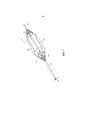
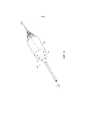
[00015]Фигура 1 - вид в перспективе надувного устройства в расширенном состоянии;[00015] Figure 1 is a perspective view of an inflatable device in an expanded state;
[00016]Фигура 2 - вид в перспективе надувного устройства в расширенном состоянии, содержащего наружный чехол или оболочку;[00016] Figure 2 is a perspective view of an inflatable device in an expanded state containing an outer cover or shell;
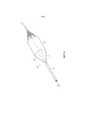
[00017]Фигура 3 - вид в перспективе надувного устройства, включающего в себя продленный чехол или оболочку, образующую клапан;[00017] Figure 3 is a perspective view of an inflatable device including an extended cover or shell defining a valve;
[00018]Фигура 4 - вид в разрезе вдоль линии 4-4, показанной на Фигуре 3, где клапан пребывает в первом положении, чтобы позволить проходить потоку через центральный проход устройства;[00018] Figure 4 is a cross-sectional viewtaken along line 4-4 of Figure 3 where the valve is in the first position to allow flow through the central passage of the device;
[00019]Фигура 5 - вид сбоку в разрезе устройства по Фигуре 4, где клапан пребывает во втором положении для ограничения потока через центральный проход устройства;[00019] Figure 5 is a cross-sectional side view of the device of Figure 4 with the valve in a second position to restrict flow through the central passage of the device;
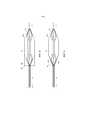
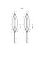
[00020]Фигура 6 - вид в перспективе надувного устройства, содержащего дополнительный вариант осуществления клапана;[00020] Figure 6 is a perspective view of an inflatable device comprising a further embodiment of a valve;
[00021]Фигура 7 - вид в разрезе вдоль линии 7-7, показанной на Фигуре 6, где клапан пребывает в первом положении для ограничения потока через центральный проход устройства;[00021] Figure 7 is a cross-sectional view along line 7-7 of Figure 6 with the valve in a first position to restrict flow through the central passage of the device;
[00022]Фигура 8 - вид сбоку в разрезе устройства по Фигуре 7, где клапан пребывает во втором положении, чтобы позволить проходить потоку через центральный проход устройства;[00022] Figure 8 is a cross-sectional side view of the device of Figure 7 with the valve in a second position to allow flow through the central passage of the device;
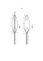
[00023]Фигура 9 - вид в перспективе надувного устройства, содержащего дополнительный вариант осуществления клапана;[00023] Figure 9 is a perspective view of an inflatable device comprising a further embodiment of a valve;
[00024]Фигура 10 - вид в разрезе вдоль линии 10-10, показанной на Фигуре 9, где клапан пребывает в первом положении для ограничения потока через центральный проход устройства;[00024] Figure 10 is a cross-sectional view along line 10-10 of Figure 9 with the valve in a first position to restrict flow through the central passage of the device;
[00025]Фигура 11 - вид сбоку в разрезе устройства по Фигуре 9, где клапан пребывает во втором положении, чтобы позволить проходить потоку через центральный проход устройства;[00025] Figure 11 is a cross-sectional side view of the device of Figure 9 with the valve in a second position to allow flow through the central passage of the device;
[00026]Фигура 12 - вид в перспективе надувного устройства, содержащего дополнительный вариант осуществления клапана;[00026] Figure 12 is a perspective view of an inflatable device comprising a further embodiment of a valve;
[00027]Фигура 13 - вид в разрезе вдоль линии 13-13, показанной на Фигуре 12, где клапан пребывает в первом положении, чтобы позволить проходить потоку через центральный проход устройства;[00027] Figure 13 is a sectional viewtaken along line 13-13 of Figure 12 with the valve in a first position to allow flow through the central passage of the device;
[00028]Фигура 14 - вид сбоку в разрезе устройства по Фигуре 13, где клапан пребывает во втором положении для ограничения потока через центральный проход устройства.[00028] Figure 14 is a cross-sectional side view of the device of Figure 13 with the valve in a second position to restrict flow through the central passage of the device.
ПОДРОБНОЕ ОПИСАНИЕDETAILED DESCRIPTION
[00029]Раскрытое изобретение относится к надувному устройству в виде перфузионного баллона. Элементы новизны изобретения подробно изложены в нижеследующей формуле изобретения. Лучшее понимание отличительных признаков и преимуществ изобретения будет получено из приведенного ниже подробного описания, в котором изложены иллюстративные варианты осуществления, использующие принципы, заложенные в изобретении, а также сопроводительных чертежей.[00029] Thedisclosed invention relates to an inflatable device in the form of a perfusion balloon. The novelties of the invention are set forth in detail in the following claims. A better understanding of the features and advantages of the invention will be obtained from the following detailed description, which sets forth illustrative embodiments employing the principles of the invention, and the accompanying drawings.
[00030]На Фигуре 1 показано надувное устройство 10, включающее в себя перфузионный баллон 12 в раздутом состоянии, готовый к использованию в связи с проведением процедуры (однако этот баллон обычно пребывает в сложенном виде в целях доставки по сосудистому руслу в выбранную область лечения, например, аортальный клапан). Изучив раздутое состояние, можно понять, что баллон 12 устройства 10 может иметь множество надувных ячеек 12a (показано восемь, но может быть создано любое число), по меньшей мере, в одном сечении баллона. Как указано на Фигуре 2, в проиллюстрированном варианте осуществления может быть создано удерживающее приспособление, такое как трубчатая гибкая оболочка или чехол 18, образующий оболочку или кожух поверх центрального участка ячеек 12a для их удерживания с сохранением в целом круговой конфигурации, которое также может служить для защиты ячеек при контакте со стенозированным клапаном и т.п. Чехол 18 может быть неподатливым, чтобы не допускать дополнительного расширения, после того как ячейки 12a полностью раздуты.[00030] Figure 1 shows an
[00031]Ячейки 12a могут представлять собой индивидуальные или дискретные баллоны, раздуваемые по отдельности. Каждая ячейка 12a имеет отдельный просвет для надувания через шейку 12b, как уже отмечалось, а также шейку 12c на дистальном конце, которые образуют в целом конусные участки баллона 12. Ячейки 12a могут быть уплотнены на дистальном кончике (например, на дистальном конце каждой шейки 12c) или могут представлять собой части единого баллона. Последнее может достигаться с помощью сегментированной удлиненной конструкции, сложенной так, чтобы заставить ячейки 12a образовывать проход P, продолжающийся вдоль центральной оси X, вдоль которой текучая среда, такая как кровь, может продолжать совершать течение, даже когда баллон полностью раздут (что может выполняться через единственный просвет для надувания, либо каждый баллон может иметь свой собственный просвет для надувания). Полное описание баллона данного типа можно найти в публикации международной патентной заявки No.WO2012099979A1. Однако могут также использоваться другие формы перфузионных баллонов, например, трубчатый баллон, баллон, имеющий периферийный (например, спиральный) канал, чтобы позволить потоку текучей среды совершать течение в процессе раздувания, либо любое сочетание этих технологий.[00031]
[00032]В любом случае устройство 10 может также включать в себя внутренний стержень или трубку 14, содержащую просвет L, продолжающийся вдоль центральной оси X, который может быть выполнен с возможностью приема проволочного направителя для направления устройства к месту проведения лечения. Внутренняя трубка 14 может образовывать часть стержня катетера или трубки 16, которая включает в себя просвет N, в котором расположена внутренняя трубка 14. Перфузионный баллон 12, в свою очередь, может крепиться к стержню 16 катетера и поддерживаться им, например, на проксимальных шейках 12b или смежно с проксимальными шейками 12b, образующими вход в проход P, который может принимать текучую среду для раздувания через просвет N.[00032] In any event,
[00033]Согласно одному аспекту данного раскрытия баллон 12 выполнен с возможностью селективно регулировать поток текучей среды через проход P. В одном раскрытом варианте осуществления это достигается с помощью клапана 20, являющегося внешним по отношению к баллону 12 (иными словами, не расположенного в проходе P или внутреннем пространстве между шейками 12b, 12c и стержнем или трубкой 14), который селективно приводится в действие пассивным образом, например продолжения 18a чехла 18. Продолжение 18a выполнено с возможностью позволить потоку проходить через проход P в первом положении или состоянии, будучи неактивированным (Фигуры 3 и 4), например, так что единственное продолжение блокирует множество входов в проход. Во втором положении или состоянии клапан 20, образованный продолжением 18a, может перекрывать вход в проход P (иными словами, пространства между шейками 12b ячеек 12a), чтобы по существу заблокировать его (см. продолжение 18a' на Фигуре 5) и тем самым задержать или предотвратить прохождение потока текучей среды, будучи активированным (что может достигаться пассивно в результате прохождения потока текучей среды в соответствующем сосуде вследствие кровообращения). Клапан, таким образом, может многократно и регулярно ограничивать или обеспечивать возможность прохождения потока текучей среды через проход P, когда баллон 12 раздут, например, в пространстве, содержащем аортальный клапан, тем самым имитируя функцию этого клапана, лишенного в этом случае возможности функционировать. Таким образом, продолжение 18a (которое может представлять собой единый элемент в данном варианте осуществления, несмотря на перекрывание одного или нескольких входов в проход P) обеспечивает выполнение функции клапана одностороннего действия в процессе процедуры с применением устройства 10.[00033] In one aspect of this disclosure,
[00034]Продолжение 18a может быть выполнено из гибкого материала, имеющего в целом трубчатую форму, и может иметь в целом круглое сечение. Материал, образующий продолжение 18a, может быть непрерывным, но также может быть создан в виде двух или более сегментов, чтобы достичь выполнения функции клапанной подачи (например, двух сегментов, чтобы смоделировать двустворчатый клапан, трех сегментов, чтобы смоделировать трехстворчатый клапан, и т.д.). Продолжение 18a может образовывать единую структуру с чехлом 18, но может также представлять собой отдельную структуру, прикрепленную к баллону 12 (либо наложенную на чехол, либо в качестве слоя, расположенного выше или ниже него). Длина продолжения 18a может выбираться так, чтобы обеспечить надлежащее перекрывание входа в проход P, будучи в сложенном виде, что, разумеется, будет зависеть от размера и геометрии баллона 12.[00034] The
[00035]Материал, образующий клапан 20, в качестве опции может быть также наделен свойствами способствовать предпочтительному складыванию, когда баллон 12 сжат, а затем расширен. Это может достигаться, например, путем использования разной толщины материала для создания гибкого шарнира или схожей структуры, заставляющей материал складываться определенным образом. Материал тела клапана может быть также снабжен линиями сгиба, складками или опорами, чтобы вызвать складывание или раскладывание предпочтительным образом с целью обеспечения того, чтобы клапан 20 расширялся или сжимался заданным образом для достижения требуемой функции клапанной подачи.[00035] The material forming the
[00036]Как уже отмечалось, внешний клапан 20 также может быть создан в виде структуры, отдельной от кожуха или чехла 18, поверх центрального участка баллона 12. В качестве примера приводится ссылка на Фигуры 6-8, где проиллюстрирован вариант осуществления, в котором клапан 20 содержит множество компонентов, таких как створки 22, для блокирования входа в проход P. Створки 22 могут частично крепиться к баллону 12 (например, к шейкам 12b) или стержню 16, например, путем закрепления на проксимальном конце створок (соответствующем проксимальному концу баллона 12, содержащему соединение со стержнем 16), но остаются незакрепленными на дистальном конце (соответствующем дистальному концу баллона, например, содержащему кончик). Положение может быть изменено на обратное, если створки 22 расположены на дистальном конце баллона 12, либо створки могут быть аналогичным образом установлены на дистальном конце.[00036] As noted, the
[00037]Таким образом, как можно понять, сравнив Фигуры 7 и 8, створки 22 могут перекрывать вход в проход P в неактивированном состоянии, а затем активироваться (22' на Фигуре 8), чтобы позволить текучей среде поступать через проход, создавая тем самым клапан одностороннего действия. Могут быть также предусмотрены один или несколько соединителей, таких как нити 24, чтобы не допустить складывания или инвертирования одной, или нескольких створок 22. Нить 24 может представлять собой тонкую гибкую структуру, такую как проволока, волокно, лента и т.п., чтобы избежать существенной задержки потока текучей среды, когда клапан 20 открыт (что может также достигаться путем прикрепления дистальных концов, например, к шейкам 12b или другому участку баллона 12).[00037] Thus, as can be understood by comparing Figures 7 and 8, the
[00038]Может быть также предусмотрена дополнительная оболочка 26, чтобы способствовать захвату и удерживанию створок 22 в целях извлечения баллона 12, когда он сдут. Такая оболочка 26 может также использоваться применительно к другим раскрытым вариантам осуществления, например, с продолжением 18a, или вариантам осуществления, описанным ниже, в том числе для извлечения клапана 20 и баллона 12, и/или для обеспечения того, чтобы функция клапанной подачи контролировалась или регулировалась.[00038] An
[00039]Другой подход к созданию внешнего клапана 20 проиллюстрирован со ссылкой на Фигуры 9-11. В данной конструкции клапан 20 содержит спиральную оплетку 28. Эта оплетка 28 может представлять собой либо удлиненный фрагмент материала, намотанный по спирали вокруг баллона 12, например, вдоль и поверх проксимальных шеек 12b, либо фрагмент материала в форме в целом усеченного конуса, разрезанного по спирали. Материал, образующий оплетку 28, может соединяться на проксимальном и дистальном концевых участках с баллоном 12 (либо напрямую посредством сцепления, либо посредством соединителя, такого как нить). Проксимальный конец в качестве альтернативы может соединяться со стержнем 16. Материал может также образовывать продолжение чехла 18.[00039] Another approach to creating an
[00040]В любом случае в проиллюстрированном варианте осуществления зазоры или вырезы, созданные указанным образом в результате применения спиральной оплетки 28, позволяют текучей среде поступать из прохода P в проксимальном направлении (см. 28' на Фигуре 11), что также может быть следствием перемещения материала, образующего спиральную оплетку 28, в аксиальном или продольном направлении. Полученные в итоге отверстия затем закрываются, когда направление потока текучей среды изменяется на обратное, чтобы не допустить прохождения потока в противоположном направлении (в том числе, возможно, вследствие сжатия материала, образующего спиральную оплетку, в продольном направлении). Таким образом, образуется клапан одностороннего действия. Вышеупомянутая оболочка (не показана) также может использоваться в данной конструкции, как и соединители или нити.[00040] In either case, in the illustrated embodiment, gaps or notches created in this way by the use of
[00041]Еще одна конструкция проиллюстрирована на Фигурах 12-14. В данном варианте осуществления фрагмент материала 30 в форме усеченного конуса накладывается поверх шеек 12b отдельно от материала, образующего кожух или оплетку. Данный материал 30 снабжен стратегически расположенными отверстиями, связанными с подвижными частями материала, таким как створки 30a. Эти створки 30a могут пассивно открываться (Фигуры 12 и 13), чтобы позволить текучей среде поступать в проход P и из него, а затем закрываться (30a' на Фигуре 14), чтобы ограничить поток. Хотя показано шесть створок 30a, нетрудно понять, что вдоль всей периферии конусного участка баллона 12 может быть обеспечено любое требуемое количество, чтобы достичь конкретной степени выполнения функции клапанной подачи. Створки 18a также могут быть в целом выровнены в продольном и окружном направлениях, как показано, либо могут быть разнесены на неодинаковые расстояния в одном или обоих этих направлениях.[00041] Another design is illustrated in Figures 12-14. In this embodiment, a piece of frusto-
[00042]Створки 30a могут быть образованы путем разрезания материала 30, который может представлять собой тонкую пленку (в противоположность кожуху или чехлу 18, который обычно изготавливается из волокон, причем так, чтобы сделать баллон 12 неподатливым, когда он раздут), так чтобы просто оставался шарнир. Таким образом, створки 30a могут свободно открываться и закрываться в ответ на прохождение потока текучей среды, тем самым по существу блокируя вход, а значит, в конечном счете, регулируя поток через проход P. Открытие и закрытие створок 30a может происходить в любом направлении. Конструкция также может быть создана в виде, моделирующем жабры рыбы, а значит, отверстия могут быть попросту выполнены в виде щелей, которые не накрыты отдельными створками 30a, а просто открываются и закрываются в результате изгибания материала.[00042] The
[00043]Для образования описанных структур могут использоваться различные материалы, в том числе представленные в публикации международной патентной заявки No.WO2012099979A1.[00043] Various materials can be used to form the described structures, including those presented in International Patent Application Publication No.WO2012099979A1 .
[00044]Вышеприведенное описание ставит целью проиллюстрировать идеи изобретения и не направлено на ограничение изобретения каким-либо конкретным типом или формой. Во всех вариантах осуществления местонахождение или ориентационное положение клапана 20 можно изменить на обратное (например, дистальное или проксимальное положение, либо изменить сторону, в которую он обращен) для проведения трансапикальной процедуры. Любые элементы, описанные в настоящем документе как единичные, могут присутствовать во множественном числе (т.е. все, что представлено в виде ʺодногоʺ, может присутствовать в количестве более одного), при этом элементы, присутствующие во множественном числе, могут использоваться по отдельности. Характеристики, раскрытые в отношении одной вариации элемента, устройства, способов или комбинации таковых, могут использоваться или применяться к другим вариациям, например, размерам, значениям разрушающего давления, формам, материалам или комбинации таковых. Любой видовой элемент некоторого класса элементов может иметь характеристики или признаки любого другого видового элемента этого класса. Такие термины, как ʺв целомʺ или ʺпо существуʺ, подразумевают, что величина может варьироваться в зависимости от обстоятельств, например до 10% от заданного значения. Вышеописанные конфигурации, элементы или собранные узлы и способы, а также их элементы для реализации изобретения, также как и вариации аспектов изобретения, могут объединяться друг с другом в любом сочетании и подвергаться изменениям наряду с их очевидными модификациями.[00044] The foregoing description is intended to illustrate the inventive ideas and is not intended to limit the invention to any particular type or form. In all embodiments, the location or orientation of the
Claims (42)
Translated fromRussianApplications Claiming Priority (3)
| Application Number | Priority Date | Filing Date | Title |
|---|---|---|---|
| US15/061,802US10625058B2 (en) | 2016-03-04 | 2016-03-04 | Perfusion balloon with external valve |
| US15/061,802 | 2016-03-04 | ||
| PCT/US2017/019872WO2017151574A1 (en) | 2016-03-04 | 2017-02-28 | Perfusion balloon with external valve |
Publications (3)
| Publication Number | Publication Date |
|---|---|
| RU2018134785A RU2018134785A (en) | 2020-04-06 |
| RU2018134785A3 RU2018134785A3 (en) | 2020-07-02 |
| RU2737627C2true RU2737627C2 (en) | 2020-12-01 |
Family
ID=58489389
Family Applications (1)
| Application Number | Title | Priority Date | Filing Date |
|---|---|---|---|
| RU2018134785ARU2737627C2 (en) | 2016-03-04 | 2017-02-28 | Device for conducting a medical procedure in a fluid medium transfer vessel (versions) |
Country Status (9)
| Country | Link |
|---|---|
| US (2) | US10625058B2 (en) |
| EP (1) | EP3423144A1 (en) |
| JP (1) | JP7197360B2 (en) |
| KR (1) | KR102728364B1 (en) |
| CN (1) | CN108601928B (en) |
| AU (1) | AU2017227554B2 (en) |
| CA (1) | CA3009368A1 (en) |
| RU (1) | RU2737627C2 (en) |
| WO (1) | WO2017151574A1 (en) |
Families Citing this family (13)
| Publication number | Priority date | Publication date | Assignee | Title |
|---|---|---|---|---|
| EP3519033A1 (en) | 2016-09-30 | 2019-08-07 | Boston Scientific Limited | Pouch forming catheter |
| US11077287B2 (en)* | 2017-10-02 | 2021-08-03 | Anlvr, Llc | Non-occluding balloon for cardiovascular drug delivery |
| CN109938893A (en)* | 2017-12-18 | 2019-06-28 | 上海微创医疗器械(集团)有限公司 | Sacculus dilating catheter and its medicinal balloon |
| CN110123489A (en)* | 2018-02-02 | 2019-08-16 | 上海微创心通医疗科技有限公司 | Dilating sacculus and sacculus dilating catheter |
| AU2018406682B2 (en) | 2018-02-05 | 2024-11-14 | Medinotec, Inc. | Airway dilation device and associated method of deployment and retrieval |
| US20210001094A1 (en)* | 2018-03-09 | 2021-01-07 | C.R. Bard, Inc. | Inflatable medical balloon with continuous fiber |
| WO2020033933A1 (en) | 2018-08-10 | 2020-02-13 | The Foundry, Llc | Vascular treatment devices |
| CN112912126A (en)* | 2018-08-29 | 2021-06-04 | 波士顿科学国际有限公司 | Multi-balloon cavity forming device |
| CN109999247A (en)* | 2019-04-26 | 2019-07-12 | 山东省千佛山医院 | A kind of Bidirectional Blood Flow arterial cannulation |
| CN111298274B (en)* | 2020-05-14 | 2020-09-22 | 上海脉全医疗器械有限公司 | Medicine balloon and using method thereof |
| CN112169123B (en)* | 2020-10-29 | 2023-03-10 | 重庆市人民医院 | Tracheal catheter |
| CN113069254A (en)* | 2021-03-30 | 2021-07-06 | 哈尔滨医科大学 | Sacculus and medical intervention apparatus |
| US20230157716A1 (en)* | 2021-11-19 | 2023-05-25 | Accumed Radial Systems, Llc | System, apparatus, and method for creating a lumen |
Citations (5)
| Publication number | Priority date | Publication date | Assignee | Title |
|---|---|---|---|---|
| US5599306A (en)* | 1994-04-01 | 1997-02-04 | Localmed, Inc. | Method and apparatus for providing external perfusion lumens on balloon catheters |
| US20090118681A1 (en)* | 2007-10-30 | 2009-05-07 | William Cook Europe, Aps | Haemostatic valve |
| US20090264820A1 (en)* | 2008-04-16 | 2009-10-22 | Abiomed, Inc. | Method and apparatus for implanting an endoluminal prosthesis such as a prosthetic valve |
| WO2013184945A1 (en)* | 2012-06-06 | 2013-12-12 | Loma Vista Medical, Inc. | Inflatable medical devices |
| WO2014063039A1 (en)* | 2012-10-18 | 2014-04-24 | Loma Vista Medical, Inc. | Reinforced inflatable medical devices |
Family Cites Families (37)
| Publication number | Priority date | Publication date | Assignee | Title |
|---|---|---|---|---|
| US4909252A (en) | 1988-05-26 | 1990-03-20 | The Regents Of The Univ. Of California | Perfusion balloon catheter |
| US5360403A (en) | 1990-05-16 | 1994-11-01 | Lake Region Manufacturing Co., Inc. | Balloon catheter with lumen occluder |
| US5181911A (en) | 1991-04-22 | 1993-01-26 | Shturman Technologies, Inc. | Helical balloon perfusion angioplasty catheter |
| CA2074304C (en) | 1991-08-02 | 1996-11-26 | Cyril J. Schweich, Jr. | Drug delivery catheter |
| US5226888A (en) | 1991-10-25 | 1993-07-13 | Michelle Arney | Coiled, perfusion balloon catheter |
| US5257974A (en)* | 1992-08-19 | 1993-11-02 | Scimed Life Systems, Inc. | Performance enhancement adaptor for intravascular balloon catheter |
| CA2188407A1 (en) | 1994-04-20 | 1995-11-02 | Ronald J. Solar | Active perfusion dilatation catheter |
| US5470314A (en) | 1994-07-22 | 1995-11-28 | Walinsky; Paul | Perfusion balloon catheter with differential compliance |
| WO1999004845A2 (en) | 1997-07-22 | 1999-02-04 | Chase Medical Inc. | Catheter having a lumen occluding balloon and method of use thereof |
| AU5333599A (en)* | 1998-08-06 | 2000-02-28 | Cardeon Corporation | Aortic catheter with porous aortic arch balloon and methods for selective aorticperfusion |
| US6210363B1 (en)* | 1999-02-23 | 2001-04-03 | Cardeon Corporation | Methods and devices for occluding a vessel and performing differential perfusion |
| WO2004026371A2 (en)* | 2002-09-20 | 2004-04-01 | Flowmedica, Inc. | Method and apparatus for selective drug infusion via an intraaortic flow diverter delivery catheter |
| US6945957B2 (en) | 2002-12-30 | 2005-09-20 | Scimed Life Systems, Inc. | Valve treatment catheter and methods |
| US20050015048A1 (en)* | 2003-03-12 | 2005-01-20 | Chiu Jessica G. | Infusion treatment agents, catheters, filter devices, and occlusion devices, and use thereof |
| US7300429B2 (en)* | 2003-03-18 | 2007-11-27 | Catharos Medical Systems, Inc. | Methods and devices for retrieval of a medical agent from a physiological efferent fluid collection site |
| US7744620B2 (en) | 2003-07-18 | 2010-06-29 | Intervalve, Inc. | Valvuloplasty catheter |
| US20050209674A1 (en)* | 2003-09-05 | 2005-09-22 | Kutscher Tuvia D | Balloon assembly (V) |
| US7537580B2 (en) | 2004-06-23 | 2009-05-26 | Boston Scientific Scimed, Inc. | Intravascular dilatation infusion catheter |
| US20060224115A1 (en)* | 2005-03-30 | 2006-10-05 | Boston Scientific Scimed, Inc. | Balloon catheter with expandable wire lumen |
| DE102005034529A1 (en) | 2005-07-23 | 2007-01-25 | Qualimed Innovative Medizinprodukte Gmbh | balloon dilatation catheter |
| US7938799B2 (en)* | 2006-08-10 | 2011-05-10 | Boston Scientific Scimed, Inc. | Medical device for vessel compatibility during high pressure infusion |
| AU2007333731A1 (en) | 2006-12-19 | 2008-06-26 | Cytyc Corporation | Asymmetric radiation dosing devices and methods for brachytherapy |
| US8758386B2 (en) | 2007-11-06 | 2014-06-24 | Daniel Gelbart | In vivo inflatable structures, for example to expand stents |
| EP3912597A1 (en)* | 2008-02-29 | 2021-11-24 | Edwards Lifesciences Corporation | Expandable member for deploying a prosthetic device |
| US7951111B2 (en) | 2008-10-10 | 2011-05-31 | Intervalve, Inc. | Valvuloplasty catheter and methods |
| CN201394277Y (en)* | 2009-02-26 | 2010-02-03 | 黄锦平 | Elastic body anti-slip sleeve for tightening one-way valve on balloon catheter |
| EP2241284B1 (en)* | 2009-04-15 | 2012-09-19 | National University of Ireland, Galway | Intravasculature devices and balloons for use therewith |
| US8828040B2 (en) | 2009-07-07 | 2014-09-09 | Thomas G. Goff | Device and methods for delivery and transfer of temporary radiopaque element |
| CA2784499C (en) | 2009-12-15 | 2017-04-18 | Edwards Lifesciences Corporation | Expansion device for treatment of vascular passageways |
| WO2012009486A2 (en)* | 2010-07-13 | 2012-01-19 | Loma Vista Medical, Inc. | Inflatable medical devices |
| CN201744061U (en)* | 2010-08-20 | 2011-02-16 | 上海中山医疗科技发展公司 | Air sac drainage tube |
| US9895517B2 (en) | 2011-01-18 | 2018-02-20 | Loma Vista Medical, Inc. | Inflatable medical devices |
| US20120209375A1 (en) | 2011-02-11 | 2012-08-16 | Gilbert Madrid | Stability device for use with percutaneous delivery systems |
| US20130226287A1 (en) | 2012-02-23 | 2013-08-29 | Boston Scientific Scimed, Inc. | Valvuloplasty device |
| WO2014179767A2 (en)* | 2013-05-03 | 2014-11-06 | C.R. Bard, Inc. | Peelable protective sheath |
| CN105208943A (en)* | 2013-05-13 | 2015-12-30 | 爱德华兹生命科学公司 | Aortic occlusion device |
| US10561496B2 (en)* | 2015-09-16 | 2020-02-18 | Edwards Lifesciences Corporation | Perfusion balloon designs |
- 2016
- 2016-03-04USUS15/061,802patent/US10625058B2/enactiveActive
- 2017
- 2017-02-28WOPCT/US2017/019872patent/WO2017151574A1/ennot_activeCeased
- 2017-02-28JPJP2018546421Apatent/JP7197360B2/enactiveActive
- 2017-02-28CNCN201780008641.3Apatent/CN108601928B/enactiveActive
- 2017-02-28KRKR1020187019956Apatent/KR102728364B1/enactiveActive
- 2017-02-28RURU2018134785Apatent/RU2737627C2/enactive
- 2017-02-28CACA3009368Apatent/CA3009368A1/enactivePending
- 2017-02-28EPEP17715835.9Apatent/EP3423144A1/enactivePending
- 2017-02-28AUAU2017227554Apatent/AU2017227554B2/enactiveActive
- 2020
- 2020-03-12USUS16/817,016patent/US11517727B2/enactiveActive
Patent Citations (5)
| Publication number | Priority date | Publication date | Assignee | Title |
|---|---|---|---|---|
| US5599306A (en)* | 1994-04-01 | 1997-02-04 | Localmed, Inc. | Method and apparatus for providing external perfusion lumens on balloon catheters |
| US20090118681A1 (en)* | 2007-10-30 | 2009-05-07 | William Cook Europe, Aps | Haemostatic valve |
| US20090264820A1 (en)* | 2008-04-16 | 2009-10-22 | Abiomed, Inc. | Method and apparatus for implanting an endoluminal prosthesis such as a prosthetic valve |
| WO2013184945A1 (en)* | 2012-06-06 | 2013-12-12 | Loma Vista Medical, Inc. | Inflatable medical devices |
| WO2014063039A1 (en)* | 2012-10-18 | 2014-04-24 | Loma Vista Medical, Inc. | Reinforced inflatable medical devices |
Also Published As
| Publication number | Publication date |
|---|---|
| KR102728364B1 (en) | 2024-11-08 |
| CA3009368A1 (en) | 2017-09-08 |
| JP2019506979A (en) | 2019-03-14 |
| CN108601928B (en) | 2022-05-17 |
| JP7197360B2 (en) | 2022-12-27 |
| NZ744538A (en) | 2024-03-22 |
| EP3423144A1 (en) | 2019-01-09 |
| US20200206484A1 (en) | 2020-07-02 |
| WO2017151574A1 (en) | 2017-09-08 |
| KR20180124016A (en) | 2018-11-20 |
| US20170252544A1 (en) | 2017-09-07 |
| AU2017227554A1 (en) | 2018-08-09 |
| CN108601928A (en) | 2018-09-28 |
| AU2017227554B2 (en) | 2021-11-04 |
| RU2018134785A (en) | 2020-04-06 |
| US11517727B2 (en) | 2022-12-06 |
| RU2018134785A3 (en) | 2020-07-02 |
| US10625058B2 (en) | 2020-04-21 |
Similar Documents
| Publication | Publication Date | Title |
|---|---|---|
| RU2737627C2 (en) | Device for conducting a medical procedure in a fluid medium transfer vessel (versions) | |
| JP6868020B2 (en) | Perfusion balloon with selectively actuable valve | |
| RU2739169C2 (en) | Device for carrying out a medical procedure in a fluid medium transfer vessel (versions) | |
| US20180043133A1 (en) | Expandable sheath and methods of use | |
| WO2017013044A1 (en) | Expandable introducer sheath | |
| CN115591087A (en) | Inflatable infusion balloon with external mesh and related methods | |
| ES3015213T3 (en) | Crimping methods | |
| JP7189863B2 (en) | A perfusion balloon having a selectively actuatable valve | |
| WO2024186557A1 (en) | Hemostatic valve for catheter applications | |
| WO2025136695A1 (en) | Guide catheter for an implant delivery apparatus |