RU2736918C1 - Broadband frequency meter for microwave signals with frequency pre-multiplication and one delay line (versions) - Google Patents
Broadband frequency meter for microwave signals with frequency pre-multiplication and one delay line (versions)Download PDFInfo
- Publication number
- RU2736918C1 RU2736918C1RU2020106015ARU2020106015ARU2736918C1RU 2736918 C1RU2736918 C1RU 2736918C1RU 2020106015 ARU2020106015 ARU 2020106015ARU 2020106015 ARU2020106015 ARU 2020106015ARU 2736918 C1RU2736918 C1RU 2736918C1
- Authority
- RU
- Russia
- Prior art keywords
- microwave power
- frequency
- phase
- input
- outputs
- Prior art date
Links
- 238000005259measurementMethods0.000abstractdescription10
- 238000006243chemical reactionMethods0.000abstractdescription8
- 239000000126substanceSubstances0.000abstract1
- 230000003111delayed effectEffects0.000description14
- 238000010586diagramMethods0.000description4
- 230000014509gene expressionEffects0.000description4
- 238000004519manufacturing processMethods0.000description1
- 230000035945sensitivityEffects0.000description1
Images


Classifications
- G—PHYSICS
- G01—MEASURING; TESTING
- G01R—MEASURING ELECTRIC VARIABLES; MEASURING MAGNETIC VARIABLES
- G01R23/00—Arrangements for measuring frequencies; Arrangements for analysing frequency spectra
- G01R23/02—Arrangements for measuring frequency, e.g. pulse repetition rate; Arrangements for measuring period of current or voltage
- G01R23/04—Arrangements for measuring frequency, e.g. pulse repetition rate; Arrangements for measuring period of current or voltage adapted for measuring in circuits having distributed constants
Landscapes
- Physics & Mathematics (AREA)
- General Physics & Mathematics (AREA)
- Radar Systems Or Details Thereof (AREA)
Abstract
Description
Translated fromRussianИзвестно устройство широкополосного измерителя частоты СВЧ сигналов [1]. Широкополосный измеритель частоты СВЧ сигналов состоит из входного широкополосного усилителя, набора линий задержки, фазовых детекторов, аналого-цифровых преобразователей, вычислительного устройства и устройства управления.The known device is a broadband microwave frequency meter [1]. The broadband microwave frequency meter consists of an input broadband amplifier, a set of delay lines, phase detectors, analog-to-digital converters, a computing device and a control device.
Недостатком данного устройства является громоздкость, вызванная необходимостью применения нескольких линий задержки, минимальное и максимальное время задержки которых для достижения заданной точности и диапазона рабочих частот должны отличаться в несколько раз. Другим недостатком указанного устройства является узкий диапазон рабочих частот, который ограничивается сложностью проектирования и изготовления широкополосной линии задержки с большим временем задержки. Еще одним недостатком указанного устройства является невысокая чувствительность устройства, ограничиваемая погонными потерями в длинных линиях задержки.The disadvantage of this device is its cumbersomeness, caused by the need to use several delay lines, the minimum and maximum delay times of which must differ several times to achieve the specified accuracy and operating frequency range. Another disadvantage of this device is the narrow range of operating frequencies, which is limited by the complexity of designing and manufacturing a broadband delay line with a long delay time. Another disadvantage of this device is the low sensitivity of the device, which is limited by linear losses in long delay lines.
Наиболее близким по технической сущности и достигаемому техническому результату к заявляемому изобретению является устройство широкополосного измерителя частоты СВЧ сигналов [2]. Широкополосный измеритель частоты СВЧ сигналов состоит из входного широкополосного усилителя-ограничителя, входного полосового СВЧ фильтра, набора линий задержки, преобразователей частоты (умножителей частоты, делителей частоты, умножителей и делителей частоты в зависимости от варианта) фазовых детекторов, вычислительного устройства.The closest in technical essence and the achieved technical result to the claimed invention is the device of a broadband microwave frequency meter [2]. The broadband frequency meter of microwave signals consists of an input broadband amplifier-limiter, an input bandpass microwave filter, a set of delay lines, frequency converters (frequency multipliers, frequency dividers, multipliers and frequency dividers, depending on the version), phase detectors, and a computing device.
Недостатком данного устройства является громоздкость, вызванная необходимостью применения нескольких линий задержки.The disadvantage of this device is its cumbersomeness, caused by the need to use several delay lines.
Техническим результатом изобретения является уменьшение габаритных размеров и массы устройства.The technical result of the invention is to reduce the overall dimensions and weight of the device.
Целью изобретения является снижение громоздкости устройства за счет использования одной линии задержки с предварительным преобразованием частоты входного сигнала путем деления и/или умножения и последующим частотным разделением сигналов.The aim of the invention is to reduce the bulkiness of the device by using a single delay line with a preliminary conversion of the frequency of the input signal by division and / or multiplication and subsequent frequency division of the signals.
Заявленный результат достигается тем, что в устройство широкополосного измерителя частоты СВЧ сигналов, состоящего из последовательно включенных входного усилителя-ограничителя, полосно-пропускающего СВЧ фильтра, первого делителя СВЧ мощности на N, N умножителей частоты, входы которых соединены с выходами делителя СВЧ мощности на N, N фазовых детекторов, выходы которых подключены к вычислительному устройству, дополнительно введены N-портовый сумматор СВЧ мощности, входы которого соединены с соответствующими выходами умножителей частоты, синфазный делитель СВЧ мощности на два, вход которого соединен с выходом N-портового сумматора СВЧ мощности, при этом один из выходов синфазного делителя СВЧ мощности на два соединен с первым входом синфазного двух-портового сумматора СВЧ мощности, а второй выход с входом линии задержки, выход линии задержки соединен со вторым входом синфазного двух-портового сумматора СВЧ мощности, выход синфазного двух-портового сумматора СВЧ мощности соединен с входом второго делителя СВЧ мощности на N, выходы второго делителя мощности на N соединены с соответствующими полосовыми фильтрами, общее количество которых N, выходы полосовых фильтров соединены с входами соответствующих фазовых детекторов.The claimed result is achieved by the fact that the device of a broadband microwave signal frequency meter, consisting of a series-connected input amplifier-limiter, a bandpass microwave filter, a first microwave power divider by N, N frequency multipliers, the inputs of which are connected to the outputs of the microwave power divider by N , N phase detectors, the outputs of which are connected to the computing device, an N-port microwave power adder is additionally introduced, the inputs of which are connected to the corresponding outputs of the frequency multipliers, an in-phase microwave power divider into two, the input of which is connected to the output of the N-port microwave power adder, when one of the outputs of the in-phase microwave power divider into two is connected to the first input of the in-phase two-port microwave power adder, and the second output to the input of the delay line, the output of the delay line is connected to the second input of the in-phase two-port microwave power adder, the output of the in-phase two-port combiner microwave power is connected to the input ohm of the second divider of microwave power by N, the outputs of the second divider of power by N are connected to the corresponding band-pass filters, the total number of which is N, the outputs of the band-pass filters are connected to the inputs of the corresponding phase detectors.
Заявленный результат также достигается тем, что в устройство широкополосного измерителя частоты СВЧ сигналов, состоящего из последовательно включенных входного усилителя-ограничителя, полосно-пропускающего СВЧ фильтра, первого делителя СВЧ мощности на M, M делителей частоты, входы которых соединены с выходами делителя СВЧ мощности на M, M фазовых детекторов, выходы которых подключены к вычислительному устройству, дополнительно введены M-портовый сумматор СВЧ мощности, входы которого соединены с соответствующими выходами делителей частоты, синфазный делитель СВЧ мощности на два, вход которого соединен с выходом M-портового сумматора СВЧ мощности, при этом один из выходов синфазного делителя СВЧ мощности на два соединен с первым входом синфазного двух-портового сумматора СВЧ мощности, а второй выход с входом линии задержки, выход линии задержки соединен со вторым входом синфазного двух-портового сумматора СВЧ мощности, выход синфазного двух-портового сумматора СВЧ мощности соединен с входом второго делителя СВЧ мощности на M, выходы второго делителя мощности на M соединены с соответствующими полосовыми фильтрами, общее количество которых M, выходы полосовых фильтров соединены с входами соответствующих фазовых детекторов.The claimed result is also achieved by the fact that in the device of a broadband microwave signal frequency meter, consisting of a series-connected input amplifier-limiter, a bandpass microwave filter, a first microwave power divider into M, M frequency dividers, the inputs of which are connected to the outputs of the microwave power divider by M, M phase detectors, the outputs of which are connected to the computing device, an M-port microwave power adder is additionally introduced, the inputs of which are connected to the corresponding outputs of the frequency dividers, an in-phase microwave power divider into two, the input of which is connected to the output of the M-port microwave power adder, wherein one of the outputs of the in-phase microwave power divider into two is connected to the first input of the in-phase two-port microwave power adder, and the second output to the input of the delay line, the output of the delay line is connected to the second input of the in-phase two-port microwave power adder, the output of the in-phase two- of the port combiner of microwave power is connected to the input One of the second microwave power divider by M, the outputs of the second power divider by M are connected to the corresponding band-pass filters, the total number of which is M, the outputs of the band-pass filters are connected to the inputs of the corresponding phase detectors.
Заявленный результат достигается также в устройстве широкополосного измерителя частоты СВЧ сигналов, состоящего из последовательно включенных входного усилителя-ограничителя, полосно-пропускающего СВЧ фильтра, первого синфазного делителя СВЧ мощности на N+M, N умножителей частоты, входы которых соединены с выходами синфазного делителя мощности на N+M, M делителей частоты, входы которых соединены с выходами синфазного делителя мощности на N+M, N+M фазовых детекторов, выходы которых подключены к вычислительному устройству, в которое дополнительно введены N+M портовый сумматор СВЧ мощности, входы которого соединены с соответствующими выходами умножителей частоты и делителей частоты, делитель СВЧ мощности на два, вход которого соединен с выходом N+M портового сумматора СВЧ мощности, при этом один из выходов делителя СВЧ мощности на два соединен с первым входом двух-портового сумматора СВЧ мощности, а второй выход с входом линии задержки, выход линии задержки соединен со вторым входом двух-портового сумматора СВЧ мощности, выход двух-портового сумматора СВЧ мощности соединен с входом второго делителя СВЧ мощности на N+M, выходы второго делителя СВЧ мощности на N+M соединены с соответствующими полосовыми фильтрами, общее количество которых N+M, выходы полосовых фильтров соединены с входами соответствующих фазовых детекторов.The claimed result is also achieved in the device of a broadband microwave signal frequency meter, consisting of a series-connected input limiter amplifier, a bandpass microwave filter, a first in-phase microwave power divider into N + M, N frequency multipliers, the inputs of which are connected to the outputs of the in-phase power divider on N + M, M frequency dividers, the inputs of which are connected to the outputs of the in-phase power divider into N + M, N + M phase detectors, the outputs of which are connected to a computing device, into which an N + M port microwave power adder is additionally introduced, the inputs of which are connected to the corresponding outputs of frequency multipliers and frequency dividers, a microwave power divider into two, the input of which is connected to the output of the N + M port microwave power combiner, while one of the outputs of the microwave power divider into two is connected to the first input of the two-port microwave power combiner, and the second output with delay line input, delay line output is connected to the second input of two -port microwave power adder, the output of the two-port microwave power adder is connected to the input of the second microwave power divider by N + M, the outputs of the second microwave power divider by N + M are connected to the corresponding bandpass filters, the total number of which is N + M, the outputs of the bandpass filters connected to the inputs of the corresponding phase detectors.
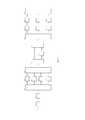
Сущность изобретения поясняется чертежами на фигурах 1,2,3. На фиг.1 представлена структурная схема широкополосного измерителя частоты СВЧ сигналов с умножителями частоты. Широкополосный измеритель частоты СВЧ сигналов содержит: входной широкополосный усилитель-ограничитель 1, полосно-пропускающий СВЧ фильтр 2, делитель 3 СВЧ мощности на N, умножители частоты 4.1…4.N, N портовый сумматор 5 СВЧ мощности, синфазный делитель 6 СВЧ мощности на два, линию 7 задержки, синфазный двух-портовый сумматор 8 СВЧ мощности, делитель 9 СВЧ мощности на N, полосно-пропускающие фильтры 10.1…10.N, фазовые детекторы 11.1…11.N, вычислительное устройство 12.The essence of the invention is illustrated by drawings in figures 1,2,3. Figure 1 shows a block diagram of a broadband frequency meter of microwave signals with frequency multipliers. The broadband microwave frequency meter contains: an input broadband amplifier-
На фиг.2 представлена структурная схема широкополосного измерителя частоты СВЧ сигналов с делителями частоты. Широкополосный измеритель частоты СВЧ сигналов содержит: входной широкополосный усилитель-ограничитель 13, полосно-пропускающий СВЧ фильтр 14, делитель 15 СВЧ мощности на M, делители частоты 16.1…16.M, M портовый сумматор 17 СВЧ мощности, синфазный делитель 18 СВЧ мощности на два, линию 19 задержки, синфазный двух-портовый сумматор 20 СВЧ мощности, делитель 21 СВЧ мощности на M, полосно-пропускающие фильтры 22.1…22.M, фазовые детекторы 23.1…23.M, вычислительное устройство 24.Figure 2 shows a block diagram of a broadband microwave frequency meter with frequency dividers. The broadband frequency meter of microwave signals contains: an input broadband amplifier-
На фиг.3 представлена структурная схема широкополосного измерителя частоты СВЧ сигналов с умножителями и делителями частоты. Широкополосный измеритель частоты СВЧ сигналов содержит: входной широкополосный усилитель-ограничитель 25, полосно-пропускающий СВЧ фильтр 26, делитель 27 СВЧ мощности на N+M, умножители частоты 28.1…28N, делители частоты 29.1…29.M, N+M портовый сумматор 30 СВЧ мощности, синфазный делитель 31 СВЧ мощности на два, линию 32 задержки, синфазный двух портовый сумматор 33 СВЧ мощности, делитель 34 СВЧ мощности на N+M, полосно-пропускающие фильтры 35.1…35.N+M, фазовые детекторы 36.1…36. N+M, вычислительное устройство 37.Figure 3 shows a block diagram of a broadband frequency meter of microwave signals with multipliers and frequency dividers. The broadband microwave frequency meter contains: an input broadband amplifier-
На фиг.4 представлена дискриминационная характеристика фазовых корреляторов.Figure 4 shows the discrimination characteristic of phase correlators.
Для удобства рассмотрим работу широкополосного измерителя частоты, функциональная схема которого представлена на фигуре 1. Широкополосный измеритель частоты СВЧ сигналов работает следующим образом. Входной гармонический СВЧ сигнал с круговой частотой ω0 поступает через усилитель-ограничитель 1 на полосно-пропускающий фильтр 2, ограничивающий входную полосу частот. Полоса пропускания фильтра 2 определяется следующим образом fн…1,9-1,95fн, где fн – нижняя частота измеряемого диапазона частот. Далее сигнал поступает на делитель 3 СВЧ мощности на N, где происходит деление мощности входного сигнала на N равных частей. Умножители частоты 4.1…4.N осуществляют функцию умножения частоты и могут быть выполнены на основе диода или транзистора, работающего в нелинейном режиме, или в виде специализированной микросхемы. Коэффициенты умножения умножителей частоты 4.1…4.N выбраны из ряда 1,2,4…A полностью или с пропусками, где А - конечное число, предельный коэффициент умножения, выбираемый из условия физической реализуемости или заданной точности измерения частоты. При коэффициенте умножения частоты одного из умножителей равном 1 преобразования частоты не происходит, и входной сигнал через делитель мощности поступает на вход N портового сумматора 5 непосредственно. Число умножителей 4.1…4.N, полосовых фильтров 10.1…10.N, фазовых детекторов 11.1…11.N определяется рабочей полосой устройства и требуемой точностью измерения частоты. Предположим, что коэффициент умножения умножителя частоты 4.1 равен n1, умножителя частоты 4.2 равен n2, умножителя частоты 4.3 равен n3, и так далее до nN, причем nN>…>n3>n2>n1. При этом на выходах умножителей 4.1,4.2,…,4.N частоты получим сигналы с частотами n1ω0, n2ω0, n3ω0,…, nNω0 соответственно. N – портовый сумматор 5 СВЧ мощности осуществляет суммирование сигналов с частотами n1ω0, n2ω0, n3ω0,…, nNω0.Двух-портовый делитель СВЧ мощности 6 делит сигналы с частотами n1ω0, n2ω0, n3ω0,…, nNω0 на две равные по мощности части. Одна из частей поступает непосредственно на один из входов синфазного двух-портового сумматора 8 СВЧ-мощности. Вторая часть поступает на вход линии 7 задержки с временем задержки равным τ. Тогда фазовые набеги, приобретаемые сигналами на выходе линии 7 задержки составят: θ1=n1ω0τ, θ2=n2ω0τ, θ3=n3ω0τ,…, θN=nNω0τ. Далее, задержанные и незадержанные сигналы с частотами n1ω0, n2ω0, n3ω0,…, nNω0 поступают на входы синфазного двух-портового сумматора 8 СВЧ мощности, где происходит их суммирование. С выхода синфазного двух-портового сумматора 8 СВЧ мощности сигналы поступают на N-портовый делитель 9 СВЧ мощности, где происходит их деление на N равных частей по мощности. Выходы N-портового делителя 9 СВЧ мощности соединены с соответствующими полосно-пропускающими фильтрами 10.1…10.N, которые осуществляют частотную селекцию задержанных и незадержанных сигналов с частотами n1ω0, n2ω0, n3ω0,…, nNω0 соответственно. Полосы пропускания фильтров 10.1…10.3 задаются выражением n1fн…1,9-1,95n1fн, n2fн…1,9-1,95n2fн, n3fн…1,9-1,95n3fн,…,nNfн…1,9-1,95nNfн. Фазовые детекторы 11.1,11.2,11.3,…,11.N на основе задержанного и незадержанного сигнала формируют следующие передаточные функции, вид которых показан на фигуре 4 (PDn1 – 1, PDn2 – 2, PDn3 - 3):For convenience, let us consider the operation of a broadband frequency meter, the functional diagram of which is shown in figure 1. A broadband microwave frequency meter operates as follows. Input harmonic microwave signal with circular frequency ω0 goes through the amplifier-


......

где An1, An2, An3, AnN – коэффициенты пропорциональности;where An1 , An2 , An3 , AnN - proportionality coefficients;
n1, n2, n3, nN – коэффициенты умножения частоты;n1, n2, n3, nN - frequency multiplication factors;
τ – время задержки линии задержки;τ is the delay time of the delay line;
ω – круговая частота.ω - circular frequency.
Детектор 11.1, имеет в рабочем диапазоне частот однозначную, но относительно пологую дискриминационную характеристику, по этой причине детектор 11.1 служит для грубой оценки частоты входного сигнала. В тоже время фазовые детекторы 11.2, 11.3,…,11.N имеют неоднозначные функции преобразования, крутизна которых выше по сравнению с крутизной передаточной функции детектора 11.1. Детекторы 11.2…11.N служат для повышения точности измерения частоты входного сигнала. Вычислительное устройство 12 предназначено определения частоты входного сигнала по напряжениям от фазовых детекторов 11.1,…,11.N.The detector 11.1 has an unambiguous but relatively flat discrimination characteristic in the operating frequency range, for this reason the detector 11.1 serves for a rough estimate of the frequency of the input signal. At the same time, phase detectors 11.2, 11.3,…, 11.N have ambiguous conversion functions, the slope of which is higher compared to the slope of the transfer function of the detector 11.1. Detectors 11.2 ... 11.N serve to improve the accuracy of measuring the frequency of the input signal.
Широкополосный измеритель частоты также может быть реализован с применением делителей частоты. Широкополосный измеритель частоты СВЧ сигналов работает следующим образом. Входной гармонический СВЧ сигнал с круговой частотой ω0 поступает через усилитель-ограничитель 13 на полосно-пропускающий фильтр 14, ограничивающий входную полосу частот. Полоса пропускания фильтра 14 определяется следующим образом fн…1,9-1,95fн, где fн – нижняя частота измеряемого диапазона частот. Далее сигнал поступает на делитель 15 СВЧ мощности на M, где происходит деление мощности входного сигнала на M равных частей. Делители частоты 16.1…16.M осуществляют функцию деления частоты и могут быть выполнены на основе нелинейных элементов или специализированных микросхем делителей частоты. Коэффициенты деления делителей частоты 16.1…16.M выбраны из ряда 1,2,4…B полностью или с пропусками, где B - конечное число, предельный коэффициент деления, выбираемый из условия физической реализуемости или заданной точности измерения частоты. При коэффициенте деления частоты одного из делителей равном 1 преобразования частоты не происходит, и входной сигнал через делитель мощности поступает на вход M портового сумматора 17 СВЧ мощности непосредственно. Число делителей 16.1…16.M частоты, полосовых фильтров 22.1…22.M, фазовых детекторов 23.1…23.M определяется рабочей полосой устройства и требуемой точностью измерения частоты. Предположим, что коэффициент деления делителя частоты 16.1 равен m1, делителя частоты 16.2 равен m2, делителя частоты 16.3 равен m3, и так далее до mM, причем mM>…>m2>m1. При этом на выходах делителей 16.1,16.2,…,16.M частоты получим сигналы с частотами ω0/m1, ω0/m2,…, ω0/mM. M – портовый сумматор 17 СВЧ мощности осуществляет суммирование сигналов с частотами ω0/m1, ω0/m2,…,ω0/mM.Двух-портовый делитель СВЧ мощности 18 делит сигналы с частотами ω0/m1, ω0/m2, ω0/m3на две равные по мощности части. Одна из частей поступает непосредственно на один из входов синфазного двух-портового сумматора 20 СВЧ-мощности. Вторая часть поступает на вход линии 19 задержки с временем задержки равным τ. Тогда фазовые набеги, приобретаемые сигналами на выходе линии 19 задержки составят: θ1=ω0τ/m1, θ2=ω0τ/m2,…,θM= ω0τ/mM. Далее, задержанные и незадержанные сигналы с частотами ω0/m1, ω0/m2,…,ω0/mM поступают на входы синфазного двух-портового сумматора 20 СВЧ мощности, где происходит их суммирование. С выхода синфазного двух-портового сумматора 20 СВЧ мощности сигналы поступают на M-портовый делитель 21 СВЧ мощности, где происходит их деление на M равных частей по мощности. Выходы M-портового делителя 21 СВЧ мощности соединены с соответствующими полосно-пропускающими фильтрами 22.1…22.M, которые осуществляют частотную селекцию задержанных и незадержанных сигналов с частотами ω0/m1, ω0/m2,…,ω0/mM соответственно. Полосы пропускания фильтров 22.1…22.M задаются выражением fн/m1…1,9-1,95fн/m1, fн/m2…1,9-1,95fн/m2,…, fн/mM…1,9-1,95fн/mM. Фазовые детекторы 23.1, 23.2,…, 23.M формируют следующие передаточные функции, вид которых показан на фигуре 4 (PDm1 – 3, PDm2 – 2, PDm3 - 1):A broadband frequency meter can also be implemented using frequency dividers. Broadband microwave frequency meter works as follows. Input harmonic microwave signal with circular frequency ω0 goes through the amplifier-


......

где Am1, Am2, Am3, AmM – коэффициенты пропорциональности;where Am1 , Am2 , Am3 , AmM - proportionality coefficients;
m1,m2,m3,mM – коэффициенты деления частоты;m1, m2, m3, mM - frequency division factors;
τ – время задержки линии задержки;τ is the delay time of the delay line;
ω – круговая частота.ω - circular frequency.
Детектор 23.M имеет в рабочем диапазоне частот однозначную, но относительно пологую дискриминационную характеристику, по этой причине детектор 23.M служит для грубой оценки частоты входного сигнала. В тоже время фазовые детекторы 23.1…23.M-1 имеют неоднозначные передаточные функции, крутизна которых выше по сравнению с крутизной передаточной функции детектора 23.M. Детекторы 23.1…23.M-1 служат для повышения точности измерения частоты входного сигнала. Вычислительное устройство 24 предназначено для определения частоты входного сигнала по напряжениям от фазовых детекторов 23.1,…,23.M. The 23.M detector has an unambiguous but relatively flat discrimination characteristic in the operating frequency range, for this reason the 23.M detector serves for a rough estimate of the frequency of the input signal. At the same time, phase detectors 23.1 ... 23.M-1 have ambiguous transfer functions, the slope of which is higher compared to the slope of the transfer function of the 23.M. detector. Detectors 23.1 ... 23.M-1 serve to improve the accuracy of measuring the frequency of the input signal. The
Широкополосный измеритель частоты также может быть реализован с применением делителей частоты и умножителей частоты. Входной гармонический СВЧ сигнал с круговой частотой ω0 поступает через усилитель-ограничитель 25 на полосно-пропускающий фильтр 26, ограничивающий входную полосу частот. Полоса пропускания фильтра 26 определяется следующим образом fн…1,9-1,95fн, где fн – нижняя частота измеряемого диапазона частот. Далее сигнал поступает на синфазный делитель 27 СВЧ мощности, где происходит деление мощности входного сигнала на N+M равных частей. Умножители частоты 28.1…28.N осуществляют функцию умножения и могут быть выполнены на основе диода или транзистора, работающего в нелинейном режиме, или в виде специализированной микросхемы. Делители частоты 29.1…29.M осуществляют функцию деления частоты и могут быть выполнены на основе нелинейных элементов или специализированных микросхем. Коэффициенты умножения умножителей частоты 28.1…28.N выбраны из ряда 1,2,4…C полностью или с пропусками, где C - конечное число, предельный коэффициент умножения, выбираемый из условия физической реализуемости или заданной точности измерения частоты. Коэффициенты деления делителей частоты 29.1…29.M выбраны из ряда 1,2,4…D полностью или с пропусками, где D - конечное число, предельный коэффициент деления, выбираемый из условия физической реализуемости или заданной точности измерения частоты. При коэффициенте умножения частоты одного из умножителей или коэффициенте деления одного из делителей частоты равном 1 преобразования частоты не происходит, и входной сигнал поступает на соответствующий вход N+M портового сумматора 30 СВЧ мощности непосредственно. Число умножителей 28.1…28.N частоты, делителей 29.1…29.M частоты, фазовых детекторов 36.1…36.N+M определяется рабочей полосой устройства и требуемой точностью измерения частоты. Предположим, что коэффициент умножения умножителя частоты 28.1 равен n1, умножителя 28.2 частоты равен n2 и так далее до nN, причем nN>…>n3>n2>n1. Коэффициенты деления делителей частоты 29.1…29.M равны m1, m2,… и так далее до mM, причем mM>…>m2>m1.. При этом на выходах умножителей 28.1,…,28.N частоты получим сигналы с частотами n1ω0, n2ω0,…,nNω0 а на выходе делителей 29.1…29.M частоты получим сигнал с частотами ω0/m1, ω0/m2,…,ω0/mM.M+N – портовый сумматор 30 СВЧ мощности осуществляет суммирование сигналов с частотами n1ω0, n2ω0,…,nNω0 и ω0/m1, ω0/m2,…,ω0/mM.Двух-портовый делитель СВЧ мощности 31 делит сигналы с частотами n1ω0, n2ω0,…,nNω0 и ω0/m1, ω0/m2, ω0/m3на две равные по мощности части. Одна из частей поступает непосредственно на один из входов синфазного двух-портового сумматора 33 СВЧ-мощности. Вторая часть поступает на вход линии 32 задержки с временем задержки равным τ. Тогда фазовые набеги, приобретаемые сигналами на выходе линии 32 задержки составят: θ1=n1ω0τ, θ2=n2ω0τ,…, θN=nNω0τ δ1=ω0τ/m1, δ2=ω0τ/m2,…, δM= ω0τ/mM. Далее, задержанные и незадержанные сигналы с частотами n1ω0, n2ω0,…,nNω0 и ω0/m1, ω0/m2,…,ω0/mM поступают на входы синфазного двух-портового сумматора 33 СВЧ мощности, где происходит их суммирование. С выхода синфазного двух-портового сумматора 33 СВЧ мощности сигналы поступают на N+M-портовый делитель 34 СВЧ мощности, где происходит их деление на N+M равных частей по мощности. Выходы N+M-портового делителя 34 СВЧ мощности соединены с соответствующими полосно-пропускающими фильтрами 35.1…35.N+M, которые осуществляют частотную селекцию задержанных и незадержанных сигналов с частотами n1ω0, n2ω0,…,nNω0 и ω0/m1, ω0/m2,…,ω0/mM соответственно. Полосы пропускания фильтров 35.1…35.N задаются выражениями n1fн…1,9-1,95n1fн, n2fн…1,9-1,95n2fн, n3fн…1,9-1,95n3fн,…,nNfн…1,9-1,95nNfн. Полосы пропускания фильтров 35.N+1…35.M задаются выражениями fн/m1…1,9-1,95fн/m1, fн/m2…1,9-1,95fн/m2,…, fн/mM…1,9-1,95fн/mM. Фазовые детекторы 36.1, 36.2,…, 36.N+M формируют следующие передаточные функции, вид которых показан на фигуре 4 (PDnN – 3, PDmM - 1):A broadband frequency meter can also be implemented using frequency dividers and frequency multipliers. Input harmonic microwave signal with circular frequency ω0 goes through the amplifier-
......


......

где An1, ..., AnN, Am1, ..., AmM – коэффициенты пропорциональности;where An1 , ..., AnN , Am1 , ..., AmM are proportionality coefficients;
n1,n2, nN – коэффициенты умножения частоты;n1, n2, nN - frequency multiplication factors;
m1, m2, mM – коэффициенты деления частоты;m1 , m2 , mM - frequency division factors;
τ – время задержки линии задержки;τ is the delay time of the delay line;
ω – круговая частота.ω - circular frequency.
Детектор 36.N+M, имеет в рабочем диапазоне частот однозначную (кривая 1), но относительно пологую передаточную функцию, по этой причине детектор 36.N+M служит для грубой оценки частоты входного сигнала. В тоже время фазовые детекторы 36.1…36.N+M-1 имеют неоднозначные передаточные функции (кривые 2 и 3 соответственно), крутизна которых выше по сравнению с крутизной передаточной функции детектора 36.N+M. Детекоры 36.1…36.N+M-1 служат для повышения точности измерения частоты входного сигнала. Вычислительное устройство 37 предназначено определения частоты входного сигнала по напряжениям от фазовых детекторов 36.1…36.N+M.The 36.N + M detector has an unambiguous (curve 1) but relatively flat transfer function in the operating frequency range, for this reason, the 36.N + M detector serves for a rough estimate of the input signal frequency. At the same time, phase detectors 36.1 ... 36.N + M-1 have ambiguous transfer functions (
Из описанных принципов работы следует, что предварительное преобразование частоты входного сигнала (умножение и/или деление) позволяет использовать частотное уплотнение для сокращения числа линий задержки до одной.From the described operating principles it follows that the preliminary conversion of the input signal frequency (multiplication and / or division) allows the use of frequency division multiplexing to reduce the number of delay lines to one.
Из описанных принципов работы понятно, что число каналов, включающих в себя делитель или умножитель частоты, линию задержки, фазовый детектор, может быть изменено для достижения заданного рабочего диапазона частот и точности измерения частоты.From the described principles of operation, it is clear that the number of channels, including a frequency divider or multiplier, a delay line, a phase detector, can be changed to achieve a given operating frequency range and frequency measurement accuracy.
Список использованных источниковList of sources used
1. Schmidt, R.O. Simultaneous signals IFM receiver using plural delay line correlators. Патент США на изобретение №54402281. Schmidt, R.O. Simultaneous signals IFM receiver using plural delay line correlators. US patent for invention No. 5440228
2. Аткишкин С.Ф., Широкополосный измеритель частоты СВЧ сигналов на линиях задержки с предварительным преобразованием частоты (варианты). Патент РФ на изобретение № RU 2710896 C12. Atkishkin SF, Broadband frequency meter of microwave signals on delay lines with preliminary frequency conversion (options). RF patent for invention No. RU 2710896 C1
Claims (3)
Translated fromRussianPriority Applications (1)
| Application Number | Priority Date | Filing Date | Title |
|---|---|---|---|
| RU2020106015ARU2736918C1 (en) | 2020-02-08 | 2020-02-08 | Broadband frequency meter for microwave signals with frequency pre-multiplication and one delay line (versions) |
Applications Claiming Priority (1)
| Application Number | Priority Date | Filing Date | Title |
|---|---|---|---|
| RU2020106015ARU2736918C1 (en) | 2020-02-08 | 2020-02-08 | Broadband frequency meter for microwave signals with frequency pre-multiplication and one delay line (versions) |
Publications (1)
| Publication Number | Publication Date |
|---|---|
| RU2736918C1true RU2736918C1 (en) | 2020-11-23 |
Family
ID=73543671
Family Applications (1)
| Application Number | Title | Priority Date | Filing Date |
|---|---|---|---|
| RU2020106015ARU2736918C1 (en) | 2020-02-08 | 2020-02-08 | Broadband frequency meter for microwave signals with frequency pre-multiplication and one delay line (versions) |
Country Status (1)
| Country | Link |
|---|---|
| RU (1) | RU2736918C1 (en) |
Citations (4)
| Publication number | Priority date | Publication date | Assignee | Title |
|---|---|---|---|---|
| US5291125A (en)* | 1992-09-14 | 1994-03-01 | The United States Of America As Represented By The Secretary Of The Air Force | Instantaneous frequency measurement (IFM) receiver with two signal capability |
| US5293114A (en)* | 1992-12-24 | 1994-03-08 | The United States Of America As Represented By The Secretary Of The Air Force | Frequency measurement receiver with means to resolve an ambiguity in multiple frequency estimation |
| RU2710096C1 (en)* | 2019-05-19 | 2019-12-24 | Сергей Федорович Аткишкин | Broadband frequency meter for microwave signals with a multitapped delay line |
| RU2710896C1 (en)* | 2019-04-03 | 2020-01-14 | Сергей Федорович Аткишкин | Broadband frequency meter for microwave signals on delay lines with preliminary frequency conversion (versions) |
- 2020
- 2020-02-08RURU2020106015Apatent/RU2736918C1/enactive
Patent Citations (4)
| Publication number | Priority date | Publication date | Assignee | Title |
|---|---|---|---|---|
| US5291125A (en)* | 1992-09-14 | 1994-03-01 | The United States Of America As Represented By The Secretary Of The Air Force | Instantaneous frequency measurement (IFM) receiver with two signal capability |
| US5293114A (en)* | 1992-12-24 | 1994-03-08 | The United States Of America As Represented By The Secretary Of The Air Force | Frequency measurement receiver with means to resolve an ambiguity in multiple frequency estimation |
| RU2710896C1 (en)* | 2019-04-03 | 2020-01-14 | Сергей Федорович Аткишкин | Broadband frequency meter for microwave signals on delay lines with preliminary frequency conversion (versions) |
| RU2710096C1 (en)* | 2019-05-19 | 2019-12-24 | Сергей Федорович Аткишкин | Broadband frequency meter for microwave signals with a multitapped delay line |
Non-Patent Citations (1)
| Title |
|---|
| Статья: "ШИРОКОПОЛОСНЫЙ ИЗМЕРИТЕЛЬ ЧАСТОТЫ СВЧ СИГНАЛОВ С ПРЕДВАРИТЕЛЬНЫМ УМНОЖЕНИЕМ ЧАСТОТЫ", Ж. ПРИБОРЫ И СИСТЕМЫ. УПРАВЛЕНИЕ, КОНТРОЛЬ, ДИАГНОСТИКА, Номер: 10 Год: 2019.* |
Similar Documents
| Publication | Publication Date | Title |
|---|---|---|
| CN107064628B (en) | High-precision frequency measurement system and method | |
| JPH0750136B2 (en) | Frequency measurement method | |
| CN102291192B (en) | Standing-wave ratio acquisition methods and device | |
| CN111766463A (en) | Vector Network Analyzer and Its Spread Spectrum Module | |
| CN212463221U (en) | Vector Network Analyzer and its Spread Spectrum Module | |
| US6208285B1 (en) | Pulse compressor for doppler tolerant radar | |
| CN102324990A (en) | Vector reflection coefficient detection circuit only using amplitude detector and detection method thereof | |
| CA2898640C (en) | Methods and devices for determining root mean square of a delta-sigma modulated signal | |
| CN111510227A (en) | A high-probability wideband signal accurate measurement system and method | |
| RU2710896C1 (en) | Broadband frequency meter for microwave signals on delay lines with preliminary frequency conversion (versions) | |
| Helton et al. | FPGA-based 1.2 GHz bandwidth digital instantaneous frequency measurement receiver | |
| RU2736918C1 (en) | Broadband frequency meter for microwave signals with frequency pre-multiplication and one delay line (versions) | |
| US7564386B2 (en) | Pre-processing data samples from parallelized data converters | |
| RU2582877C1 (en) | Adaptive compensator of passive interference phase | |
| RU2710096C1 (en) | Broadband frequency meter for microwave signals with a multitapped delay line | |
| CN102436365A (en) | Method and device for converting high-speed linear spectrum data into logarithmic data | |
| Liu et al. | A digital correlation receiver for the Mingantu Spectral Radioheliograph | |
| RU2725505C1 (en) | Method for real-time measurement of microwave frequency | |
| CN111698036A (en) | Multi-microwave signal frequency estimation method based on microwave photons | |
| RU2723983C1 (en) | Frequency meter of microwave signals on delay lines with negative time of group delay | |
| RU2747440C1 (en) | Method for quick measurement of the microwave frequency with prior multiplication of the frequency and reduced requirements for the bandwidth of the delay line | |
| Cooper | 3.5. Autocorrelation Spectrometers | |
| CN115276832A (en) | Multi-point bandwidth frequency band microwave diagnosis system based on double comb-shaped frequencies | |
| JPS59116562A (en) | Estimating system of signal incident angle | |
| RU2724127C1 (en) | Method of measuring signal frequency in a device for rapid measurement of interference type on delay lines |