RU2736776C2 - Methods, devices and systems for receiving and decoding signals in the presence of noise using sections and deformation - Google Patents
Methods, devices and systems for receiving and decoding signals in the presence of noise using sections and deformationDownload PDFInfo
- Publication number
- RU2736776C2 RU2736776C2RU2017127771ARU2017127771ARU2736776C2RU 2736776 C2RU2736776 C2RU 2736776C2RU 2017127771 ARU2017127771 ARU 2017127771ARU 2017127771 ARU2017127771 ARU 2017127771ARU 2736776 C2RU2736776 C2RU 2736776C2
- Authority
- RU
- Russia
- Prior art keywords
- frequency
- slices
- slice
- receiver
- signal
- Prior art date
Links
- 238000000034methodMethods0.000titleclaimsdescription90
- 230000006870functionEffects0.000claimsabstractdescription81
- 238000005070samplingMethods0.000claimsdescription26
- 230000001131transforming effectEffects0.000claimsdescription5
- 230000009466transformationEffects0.000claimsdescription4
- 230000003111delayed effectEffects0.000claimsdescription3
- 238000004891communicationMethods0.000abstractdescription9
- 230000000694effectsEffects0.000abstractdescription3
- 230000009467reductionEffects0.000abstractdescription3
- 239000000126substanceSubstances0.000abstract1
- 239000013598vectorSubstances0.000description54
- 238000001514detection methodMethods0.000description24
- 230000000875corresponding effectEffects0.000description13
- 238000004364calculation methodMethods0.000description12
- 230000008569processEffects0.000description11
- 238000012545processingMethods0.000description8
- 238000001914filtrationMethods0.000description7
- 230000010363phase shiftEffects0.000description6
- 238000007906compressionMethods0.000description5
- 230000006835compressionEffects0.000description5
- 238000005314correlation functionMethods0.000description5
- 230000003321amplificationEffects0.000description4
- 230000009286beneficial effectEffects0.000description4
- 230000008901benefitEffects0.000description4
- 239000002609mediumSubstances0.000description4
- 238000003199nucleic acid amplification methodMethods0.000description4
- 238000012360testing methodMethods0.000description4
- 230000005540biological transmissionEffects0.000description3
- 238000010586diagramMethods0.000description3
- 238000007781pre-processingMethods0.000description3
- 230000002829reductive effectEffects0.000description3
- 239000003990capacitorSubstances0.000description2
- 230000008859changeEffects0.000description2
- 230000007423decreaseEffects0.000description2
- 238000013461designMethods0.000description2
- 230000007613environmental effectEffects0.000description2
- 238000009472formulationMethods0.000description2
- 239000000203mixtureSubstances0.000description2
- 238000012986modificationMethods0.000description2
- 230000004048modificationEffects0.000description2
- 230000000737periodic effectEffects0.000description2
- 230000000717retained effectEffects0.000description2
- 210000001015abdomenAnatomy0.000description1
- 238000009825accumulationMethods0.000description1
- 239000000654additiveSubstances0.000description1
- 230000000996additive effectEffects0.000description1
- 230000002411adverseEffects0.000description1
- 238000004458analytical methodMethods0.000description1
- 238000013459approachMethods0.000description1
- 239000012736aqueous mediumSubstances0.000description1
- 238000003491arrayMethods0.000description1
- 230000002238attenuated effectEffects0.000description1
- 230000001427coherent effectEffects0.000description1
- 239000002131composite materialSubstances0.000description1
- 238000012790confirmationMethods0.000description1
- 239000000470constituentSubstances0.000description1
- 238000012937correctionMethods0.000description1
- 230000002596correlated effectEffects0.000description1
- 239000013078crystalSubstances0.000description1
- 230000001186cumulative effectEffects0.000description1
- 238000013144data compressionMethods0.000description1
- 230000003247decreasing effectEffects0.000description1
- 230000001934delayEffects0.000description1
- 230000001419dependent effectEffects0.000description1
- 238000011161developmentMethods0.000description1
- 230000002496gastric effectEffects0.000description1
- 230000010354integrationEffects0.000description1
- 230000009191jumpingEffects0.000description1
- 230000000670limiting effectEffects0.000description1
- 238000004519manufacturing processMethods0.000description1
- 238000012544monitoring processMethods0.000description1
- 238000010606normalizationMethods0.000description1
- 230000004044responseEffects0.000description1
- 230000035945sensitivityEffects0.000description1
- 230000006641stabilisationEffects0.000description1
- 238000011105stabilizationMethods0.000description1
- 230000003068static effectEffects0.000description1
- 230000001629suppressionEffects0.000description1
- 230000001360synchronised effectEffects0.000description1
- 238000012546transferMethods0.000description1
Images


Classifications
- H—ELECTRICITY
- H04—ELECTRIC COMMUNICATION TECHNIQUE
- H04L—TRANSMISSION OF DIGITAL INFORMATION, e.g. TELEGRAPHIC COMMUNICATION
- H04L25/00—Baseband systems
- H04L25/02—Details ; arrangements for supplying electrical power along data transmission lines
- H04L25/08—Modifications for reducing interference; Modifications for reducing effects due to line faults ; Receiver end arrangements for detecting or overcoming line faults
- H—ELECTRICITY
- H04—ELECTRIC COMMUNICATION TECHNIQUE
- H04B—TRANSMISSION
- H04B1/00—Details of transmission systems, not covered by a single one of groups H04B3/00 - H04B13/00; Details of transmission systems not characterised by the medium used for transmission
- H04B1/0003—Software-defined radio [SDR] systems, i.e. systems wherein components typically implemented in hardware, e.g. filters or modulators/demodulators, are implented using software, e.g. by involving an AD or DA conversion stage such that at least part of the signal processing is performed in the digital domain
- H04B1/0007—Software-defined radio [SDR] systems, i.e. systems wherein components typically implemented in hardware, e.g. filters or modulators/demodulators, are implented using software, e.g. by involving an AD or DA conversion stage such that at least part of the signal processing is performed in the digital domain wherein the AD/DA conversion occurs at radiofrequency or intermediate frequency stage
- H04B1/001—Channel filtering, i.e. selecting a frequency channel within the SDR system
- H—ELECTRICITY
- H04—ELECTRIC COMMUNICATION TECHNIQUE
- H04L—TRANSMISSION OF DIGITAL INFORMATION, e.g. TELEGRAPHIC COMMUNICATION
- H04L27/00—Modulated-carrier systems
- H04L27/0014—Carrier regulation
- H—ELECTRICITY
- H04—ELECTRIC COMMUNICATION TECHNIQUE
- H04L—TRANSMISSION OF DIGITAL INFORMATION, e.g. TELEGRAPHIC COMMUNICATION
- H04L27/00—Modulated-carrier systems
- H04L27/10—Frequency-modulated carrier systems, i.e. using frequency-shift keying
- H04L27/14—Demodulator circuits; Receiver circuits
- H04L27/144—Demodulator circuits; Receiver circuits with demodulation using spectral properties of the received signal, e.g. by using frequency selective- or frequency sensitive elements
- H04L27/148—Demodulator circuits; Receiver circuits with demodulation using spectral properties of the received signal, e.g. by using frequency selective- or frequency sensitive elements using filters, including PLL-type filters
- H—ELECTRICITY
- H04—ELECTRIC COMMUNICATION TECHNIQUE
- H04L—TRANSMISSION OF DIGITAL INFORMATION, e.g. TELEGRAPHIC COMMUNICATION
- H04L69/00—Network arrangements, protocols or services independent of the application payload and not provided for in the other groups of this subclass
- H04L69/22—Parsing or analysis of headers
- H—ELECTRICITY
- H04—ELECTRIC COMMUNICATION TECHNIQUE
- H04L—TRANSMISSION OF DIGITAL INFORMATION, e.g. TELEGRAPHIC COMMUNICATION
- H04L7/00—Arrangements for synchronising receiver with transmitter
- H04L7/04—Speed or phase control by synchronisation signals
- H04L7/041—Speed or phase control by synchronisation signals using special codes as synchronising signal
- H04L7/042—Detectors therefor, e.g. correlators, state machines
Landscapes
- Engineering & Computer Science (AREA)
- Computer Networks & Wireless Communication (AREA)
- Signal Processing (AREA)
- Physics & Mathematics (AREA)
- Spectroscopy & Molecular Physics (AREA)
- Power Engineering (AREA)
- Computer Security & Cryptography (AREA)
- Noise Elimination (AREA)
- Measurement And Recording Of Electrical Phenomena And Electrical Characteristics Of The Living Body (AREA)
- Digital Transmission Methods That Use Modulated Carrier Waves (AREA)
- Radar Systems Or Details Thereof (AREA)
- Circuits Of Receivers In General (AREA)
Abstract
Description
Translated fromRussianУровень техникиState of the art
Известны проглатываемые датчики, которые могут содержать средство связи малой мощности для передачи сигналов, принимаемых приемником, который пользователь может носить на теле. Традиционные "системы связи с телом" должны быть способны обрабатывать передаваемые с высокой скоростью необработанные данные за установленный период времени с учетом доступной потребляемой мощности и емкости памяти. В традиционном приемнике поступающий сигнал проходит через аналоговые внешние интерфейсные аппаратные средства, содержащие аналоговые фильтры и аналоговые электронные усилители. Аналоговый фильтр обычно имеет широкую полосу пропускания, позволяющую обнаруживать сигналы, передаваемые на всех возможных частотах в соответствии с допустимым отклонением частоты передатчика. Поскольку аналоговые внешние интерфейсные аппаратные средства обеспечивают ограниченную фильтрацию, они пропускают значительное количество шума вместе с желаемым сигналом. После аналогового усиления и фильтрации сигнал оцифровывается аналого-цифровым преобразователем (АЦП). Остальная часть обработки принимаемого сигнала может осуществляться в цифровых аппаратных средствах, таких как встроенный микропроцессор, конечный автомат, логическая вентильная матрица, среди прочих. Оцифрованный сигнал может проходить через один или несколько узкополосных цифровых фильтров с целью максимального удаления шума до попытки его декодировать.Swallowable sensors are known that may include low power communication means for transmitting signals received by a receiver that the user may wear on the body. Traditional "body-to-body communications" must be able to process raw data transmitted at high speed over a set period of time based on available power consumption and memory capacity. In a traditional receiver, the incoming signal passes through analog external interface hardware containing analog filters and analog electronic amplifiers. An analog filter usually has a wide bandwidth to detect signals transmitted at all possible frequencies according to the transmitter frequency tolerance. Because analog front-end hardware provides limited filtering, it passes a significant amount of noise along with the desired signal. After analog amplification and filtering, the signal is digitized by an analog-to-digital converter (ADC). The rest of the processing of the received signal can be done in digital hardware, such as an embedded microprocessor, state machine, logic gate array, among others. The digitized signal can pass through one or more narrowband digital filters to remove noise as much as possible before attempting to decode it.
В тех случаях, когда приемник рассчитывает несущую частоту со значительной степенью неопределенности, требуется, чтобы приемник начинал прием через более широкополосный цифровой фильтр и, соответственно, принимал большее количество шума. Большее количество шума означает, что слабый сигнал может быть полностью пропущен. Тем не менее, чтобы отбрасывать большую часть шума, в приемнике может применяться цифровой фильтр с узкой полосой пропускания. Однако, если центр полосы пропускания узкополосного фильтра соответствует неверной несущей частоте, поступающий сигнал может быть полностью пропущен. Соответственно, с целью эффективного обнаружения и декодирования поступающего сигнала, необходимо достичь равновесия между узкополосными фильтрами для удаления максимального числа шума и фильтрами с более широкой полосой пропускания для повышения вероятности того, что несущая частота сигнала будет захвачена, когда приемнику точно неизвестна несущая частота поступающего сигнала. Соответственно, приемник может быть сконфигурирован на итерационную корректировку средней частоты узкополосного фильтра, ее перенос в новое положение и затем еще одну попытку обнаружения. Этот процесс поиска несущей частоты с использованием узкополосного фильтра занимает много времени и является энергоемким. Что важно, для повторной фильтрации на новой средней частоте приемник должен сохранять в памяти копию записи исходных данных или при недоступности исходных данных получать запись совершенно новых данных. Этот процесс требует не только значительных ресурсов памяти (в особенности при использовании АЦП с высокой разрешающей способностью), но также затрат значительного ресурса аккумуляторной батареи устройства всего лишь для идентификации несущей частоты поступающего сигнала.In cases where the receiver calculates the carrier frequency with a significant degree of uncertainty, the receiver is required to start receiving through a wider digital filter and thus receive more noise. More noise means that a weak signal can be missed entirely. However, a narrow bandwidth digital filter can be used in the receiver to reject most of the noise. However, if the center of the passband of the notch filter is at the wrong carrier frequency, the incoming signal may be completely missed. Accordingly, in order to efficiently detect and decode the incoming signal, it is necessary to achieve a balance between narrowband filters to remove the maximum amount of noise and filters with a wider bandwidth to increase the likelihood that the signal carrier frequency will be locked when the receiver does not know exactly the carrier frequency of the incoming signal. Accordingly, the receiver can be configured to iteratively adjust the center frequency of the notch filter, move it to a new position, and then try again. This process of searching for the carrier frequency using a notch filter is time consuming and energy intensive. Importantly, in order to re-filter at a new center frequency, the receiver must keep a copy of the original data record in memory, or, if the original data is not available, receive a completely new data record. This process requires not only significant memory resources (especially when using a high-resolution ADC), but also consumes a significant device battery life just to identify the carrier frequency of the incoming signal.
Сущность изобретенияThe essence of the invention
Согласно первой особенности настоящего изобретения предложен способ по п.п. 1-16.According to a first aspect of the present invention, there is provided a method according to claims. 1-16.
Согласно второй особенности настоящего изобретения предложен приемник сигналов по п.п. 17-34.According to a second aspect of the present invention, there is provided a signal receiver according to claims. 17-34.
Согласно третьей особенности настоящего изобретения предложен способ по п.п. 35-39.According to a third aspect of the present invention, a method according to claims. 35-39.
Согласно четвертой особенности настоящего изобретения предложен приемник по п.п. 40-44.According to a fourth aspect of the present invention, there is provided a receiver according to claims. 40-44.
Согласно пятой особенности настоящего изобретения предложен способ по п.п. 45-52.According to the fifth aspect of the present invention, there is provided a method according to claims. 45-52.
Согласно шестой особенности настоящего изобретения предложен способ по п.п. 53-61.According to a sixth aspect of the present invention, there is provided a method according to claims. 53-61.
Согласно седьмой особенности настоящего изобретения предложен способ по п.п. 62-65.According to a seventh aspect of the present invention, there is provided a method according to claims. 62-65.
Согласно восьмой особенности настоящего изобретения предложен способ по п.п. 66 и 67.According to an eighth aspect of the present invention, there is provided a method according to claims. 66 and 67.
Согласно девятой особенности настоящего изобретения предложен способ по п.п. 68-72.According to the ninth aspect of the present invention, there is provided a method according to claims. 68-72.
Согласно десятой особенности настоящего изобретения предложен способ по п.п. 73-79.According to a tenth aspect of the present invention, there is provided a method according to claims. 73-79.
Согласно одной из дополнительных особенностей настоящего изобретения предложена программа. Такая программа может использоваться как таковая или на программоносителе.In accordance with an additional aspect of the present invention, a program is provided. Such a program can be used as such or on a carrier.
Программоносителем может являться среда для записи или другой носитель данных. Передающей средой может являться сигнал.The storage medium can be a recording medium or other storage medium. The transmission medium can be a signal.
В одном из вариантов осуществления способ может включать прием и дискретизацию сигнала. В сигнале может быть закодирован пакет данных. Может генерироваться и сохраняться срез, содержащий пару значений для каждого из заданного числа выборок сигнала. Затем может обнаруживаться присутствие пакета данных, и обнаруженный пакет может декодироваться из сохраненных срезов. Выборки сигнала могут представлять корреляцию сигнала с эталонными функциями в приемнике. Генерирование и сохранение срезов может осуществляться по мере дискретизации принимаемого сигнала. Дискретные значения сигнала могут отбрасываться по мере генерирования и сохранения срезов. Представлением сигнала в виде срезов можно манипулировать с целью генерирования фильтров с гибкой полосой пропускания и средней частотой.In one embodiment, the method may include receiving and sampling a signal. A data packet can be encoded in the signal. A slice can be generated and stored containing a pair of values for each of a given number of signal samples. The presence of a data packet can then be detected and the detected packet can be decoded from the stored slices. The signal samples can represent the correlation of the signal with the reference functions at the receiver. Slices can be generated and saved as the received signal is sampled. Discrete signal values can be discarded as slices are generated and stored. The slice representation of the signal can be manipulated to generate filters with flexible bandwidth and center frequency.
В одном из вариантов осуществления способ обнаружения и декодирования сигнала, поступающего в приемник, может начинаться с приема поступающего сигнала приемником, необязательного выполнения какой-либо предварительной аналоговой обработки (например, усиления и фильтрации) в аналоговых внешних интерфейсных аппаратных средствах, после чего может осуществляться дискретизация предварительно обработанных данных в АЦП. Затем в одном из вариантов осуществления дискретные необработанные данные могут сравниваться с внутренними контрольными шаблонами, хранящимися в памяти, с использованием, например, алгоритма корреляции. Один из типичных методов включает корреляцию дискретизированного поступающего сигнала с заданными контрольными шаблонами на протяжении определенного периода времени.In one embodiment, a method for detecting and decoding a signal arriving at a receiver may begin by receiving the incoming signal at the receiver, optionally performing any analog preprocessing (e.g., amplification and filtering) in the analog external interface hardware, and then sampling pre-processed data in the ADC. Then, in one embodiment, the discrete raw data can be compared to internal reference patterns stored in memory using, for example, a correlation algorithm. One typical technique involves correlating a sampled incoming signal with predetermined pilot patterns over a period of time.
В вариантах осуществления изобретения решены задачи захвата и хранения большого числа поступающих с высокой скоростью дискретизированных сигналов, что создает нагрузку как на вычислительные возможности, так и емкость памяти. Обе эти задачи решены в вариантах осуществления изобретения за счет захвата "срезов". В одном из вариантов осуществления представление данных в виде срезов обеспечивает достаточно информации для эффективного и компактного представления поступающего сигнала и реализации фильтров по большей части с любой полосой пропускания. В одном из вариантов осуществления срезы могут подвергаться операции деформирования, путем которой наборы срезов трансформируются выгодными способами с целью завершения процесса обнаружения. В действительности, в одном из вариантов осуществления срезы могут объединяться с целью создания фильтров с избирательно широкими или узкими полосами пропускания. В вариантах осуществления операция деформирования может быть сконфигурирована на трансформацию срезов, захваченных на одной частоте, в срезы на другой соседней частоте. Эта операция деформирования может осуществляться посредством алгоритма, сконфигурированного на определение несущей частоты поступающего сигнала и обнаружение пакетов данных в зашумленной среде. Представление параметров сигнала в виде срезов в сочетании с функцией деформирования согласно вариантам осуществления обеспечивает новый и эффективный способ выполнения сложных алгоритмов обнаружения с использованием ограниченных ресурсов аппаратных средств и памяти.Embodiments of the invention address the problem of capturing and storing a large number of high-speed, sampled signals, which imposes a load on both computing power and memory capacity. Both of these objectives are achieved in embodiments of the invention by capturing "slices". In one embodiment, the slice representation of the data provides sufficient information to efficiently and compactly represent the incoming signal and implement filters with most of any bandwidth. In one embodiment, the slices may undergo a deformation operation, whereby sets of slices are transformed in beneficial ways to complete the detection process. In fact, in one embodiment, the cuts can be combined to create filters with selectively wide or narrow bandwidths. In embodiments, the deforming operation may be configured to transform slices captured at one frequency into slices at another adjacent frequency. This warping operation can be performed by an algorithm configured to detect the carrier frequency of the incoming signal and detect data packets in a noisy environment. The slice representation of signal parameters in combination with a warp function according to embodiments provides a novel and efficient way of performing complex detection algorithms using limited hardware and memory resources.
Дополнительные признаки настоящего изобретения станут ясны и следующего описания примеров его осуществления со ссылкой на прилагаемые чертежи.Additional features of the present invention will become clear and the following description of examples of its implementation with reference to the accompanying drawings.
Краткое описание чертежейBrief Description of Drawings
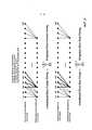
На фиг. 1 показаны различные формы сигналов и типичный срез согласно одному из вариантов осуществления, а также система, в которую входит передатчик и приемник, сконфигурированные согласно одному из вариантов осуществления.FIG. 1 shows various waveforms and a typical slice according to one embodiment, as well as a system that includes a transmitter and a receiver configured according to one embodiment.
На фиг. 2А показана корреляция дискретизированных сигналов двух форм.FIG. 2A shows the correlation of sampled signals of the two waveforms.
На фиг. 2Б показан способ расчета одного члена (в данном случае синусоидального члена) согласно одному из вариантов осуществления.FIG. 2B shows a method for calculating one term (in this case, a sinusoidal term) according to one embodiment.
На фиг. 3 показаны особенности способа расчета члена объединенного среза (в данном случае косинусоидального члена) согласно одному из вариантов осуществления.FIG. 3 shows the features of a method for calculating a merged slice term (in this case, a cosine term) according to one embodiment.
На фиг. 4 показаны особенности способа объединения синусоидального и косинусоидального членов среза с целью формирования более длинной корреляции согласно одному из вариантов осуществления.FIG. 4 illustrates the features of a method for combining sinusoidal and cosine slice terms to generate a longer correlation, according to one embodiment.
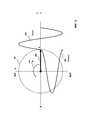
На фиг. 5 показана фаза сигнала, представленного как вращающийся вектор в системе полярных координат.FIG. 5 shows the phase of a signal represented as a rotating vector in a polar coordinate system.
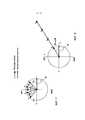
На фиг. 6А показан вращающийся вектор на опорной частоте в системе полярных координат.FIG. 6A shows a rotating vector at a reference frequency in polar coordinates.
На фиг. 6Б показан вращающийся вектор на опорной частоте и вращающийся вектор сигнала на большей, чем опорная частота, частоте в системе полярных координат.FIG. 6B shows a rotating vector at a reference frequency and a rotating signal vector at a frequency greater than the reference frequency in the polar coordinate system.
На фиг. 6В показан вращающийся вектор на опорной частоте и вращающийся вектор сигнала на меньшей, чем опорная частота, частоте в системе полярных координат.FIG. 6B shows a rotating vector at a reference frequency and a rotating signal vector at a frequency lower than the reference frequency in polar coordinates.
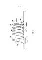
На фиг. 7 показаны особенности деформирования согласно одному из вариантов осуществления.FIG. 7 shows the features of deformation according to one embodiment.
На фиг. 8 показаны деформированные, совмещенные и готовые к объединению срезы согласно одному из вариантов осуществления.FIG. 8 shows warped, aligned, and ready-to-merge slices in accordance with one embodiment.
На фиг. 9 показаны особенности способа поиска несущей частоты и использованием деформирования срезов согласно одному из вариантов осуществления.FIG. 9 shows the features of a method for searching for a carrier frequency and using slice warping according to one embodiment.
На фиг. 10 показаны особенности обнаружения несущей методом частотной манипуляция (ЧМн) согласно одному из вариантов осуществления.FIG. 10 illustrates the features of frequency shift keying (FSK) carrier detection in accordance with one embodiment.
На фиг. 11 показаны особенности обнаружения несущей методом ЧМн с точной настройкой согласно одному из вариантов осуществления.FIG. 11 illustrates features of a finely tuned FSK carrier according to one embodiment.
На фиг. 12 показана логическая блок-схема способа обнаружения сигнала согласно одному из вариантов осуществления.FIG. 12 is a flow chart of a method for detecting a signal in accordance with one embodiment.
На фиг. 13 показана логическая блок-схема способа согласно одному из вариантов осуществления.FIG. 13 shows a flow diagram of a method in accordance with one embodiment.
Подробное описание изобретенияDetailed description of the invention
На фиг. 1 показана система согласно одному из вариантов осуществления, в которую входят маломощный передатчик 102 колебательных сигналов и приемник 104. Показано, что передатчик 102 колебательных сигналов и приемник 104 могут быть разделены каналом 103 связи. Например, передатчик 102 колебательных сигналов может находиться внутри проглатываемого датчика, сигналы 105 которого принимает приемник 104, который пользователь может носить на теле, например, на коже 106. В этом случае каналом 103 связи может являться водная среда тела. Приемник 104 может содержать аналоговые внешние интерфейсные аппаратные средства, в которых принимаемый сигнал может подвергаться предварительной обработке до его ввода в АЦП 110, который может генерировать временной ряд выборок необработанных цифровых данных. Выборки могут быть представлены, например, как 1-24 разрядные двоичные числа. Приемник 104 может содержать контроллер 112, который может быть связан с памятью 114. Память 114 может быть сконфигурирована на хранение, как подробно описано далее, данных в виде срезов, контрольных шаблонов и других временных переменных, необходимых контроллеру 112. Приемник также может содержать связной интерфейс (не показанный), позволяющий передавать во внешний мир декодированную полезную нагрузку пакетов, закодированную в принимаемом сигнале.FIG. 1 illustrates a system in accordance with one embodiment that includes a low
В одном из вариантов осуществления реализованный в компьютере способ обнаружения и декодирования сигнала, поступающего в приемник 104, может начинаться с приема поступающего сигнала 105 приемником 104, выполнения какой-либо предварительной аналоговой обработки (например, усиления и фильтрации) в аналоговых внешних интерфейсных аппаратных средствах 108, после чего может осуществляться дискретизация предварительно обработанных данных в АЦП 110. Затем в одном из вариантов осуществления дискретные необработанные данные могут сравниваться контроллером 112 с внутренними контрольными шаблонами, хранящимися в памяти 114, с использованием алгоритма корреляции. Один из методов включает корреляцию дискретизированного поступающего сигнала с заданными контрольными шаблонами на протяжении определенного периода времени.In one embodiment, a computer-implemented method for detecting and decoding a signal arriving at a
В вариантах осуществления изобретения решены задачи захвата и хранения большого числа поступающих с высокой скоростью дискретизированных сигналов, что создает нагрузку как на вычислительные возможности, так и емкость памяти. Обе эти задачи решены в вариантах осуществления изобретения за счет захвата "срезов". В одном из вариантов осуществления представление данных в виде срезов обеспечивает достаточно информации для эффективного и компактного представления поступающего сигнала и реализации фильтров по большей части с любой полосой пропускания. В одном из вариантов осуществления срезы могут подвергаться операции деформирования, путем которой наборы срезов трансформируются выгодными способами с целью завершения процесса обнаружения. В действительности, в одном из вариантов осуществления срезы могут объединяться с целью создания фильтров с избирательно широкими или узкими полосами пропускания. В вариантах осуществления операция деформирования может быть сконфигурирована на трансформацию срезов, захваченных на одной частоте, в срезы на другой соседней частоте. Эта операция деформирования может осуществляться посредством алгоритма, сконфигурированного на определение несущей частоты поступающего сигнала и обнаружение пакетов данных в зашумленной среде. Представление параметров сигнала в виде срезов в сочетании с функцией деформирования согласно вариантам осуществления обеспечивает новый и эффективный способ выполнения сложных алгоритмов обнаружения с использованием ограниченных ресурсов аппаратных средств и памяти. Например, для выполнения описанной в изобретении обработки может использоваться одна или несколько программируемых пользователем вентильных матриц (FPGA) или специализированных интегральных схем (ASIC). Также с выгодой может использоваться цифровой процессор сигналов (DSP).Embodiments of the invention address the problem of capturing and storing a large number of high-speed, sampled signals, which imposes a load on both computing power and memory capacity. Both of these objectives are achieved in embodiments of the invention by capturing "slices". In one embodiment, the slice representation of the data provides sufficient information to efficiently and compactly represent the incoming signal and implement filters with most of any bandwidth. In one embodiment, the slices may undergo a deformation operation, whereby sets of slices are transformed in beneficial ways to complete the detection process. In fact, in one embodiment, the cuts can be combined to create filters with selectively wide or narrow bandwidths. In embodiments, the deforming operation may be configured to transform slices captured at one frequency into slices at another adjacent frequency. This warping operation can be performed by an algorithm configured to detect the carrier frequency of the incoming signal and detect data packets in a noisy environment. The slice representation of signal parameters in combination with a warp function according to embodiments provides a novel and efficient way of performing complex detection algorithms using limited hardware and memory resources. For example, one or more field programmable gate arrays (FPGAs) or application specific integrated circuits (ASICs) can be used to perform the processing described in the invention. A digital signal processor (DSP) can also be used to advantage.
СрезSlice
В одном из вариантов осуществления предложена конструкция среза. Короткие корреляции, достигаемые в результате корреляции относительно короткого участка поступающего сигнала (например, приблизительно 4-8 циклов), именуются срезами. В одном из вариантов осуществления интервал среза может быть охарактеризован как заданный период времени. На фиг. 1 показаны различные сегменты сигнала с частотой 20000 Гц. Позицией 102 обозначен один цикл такого сигнала, период Т которого равен 1/20000 Гц или 50 мкс. Позицией 104 обозначен один интервал среза, равный 4 циклам сигнала с частотой 20000 Гц или 200 мкс. В данном случае интервал среза произвольно принят за 4 цикла поступающего сигнала. Тем не менее, интервал среза может соответствовать другому временному интервалу или числу циклов. Например, интервал среза может соответствовать периоду времени, равному 8 циклам. Если конкретно не указано иное, далее интервал среза считается содержащим 4 цикла поступающего сигнала, при этом ясно, что могут быть легко реализованы другие интервалы срезов. Например, срез может выражаться в циклах, но необязательно должен содержать множество полных циклов какого-либо сигнала или шаблона. Срез может соответствовать любому заданному количеству времени. Длительность среза может быть при необходимости изменена в приемнике. Например, в приемнике могут быть реализованы две программы одновременного захвата двух потоков срезов, например, одного с частотой 20 кГц и другого с частотой 12,5 кГц. При вычислении обоих срезов могут использоваться две различные длительности срезов, применимые для каждого канала. Как обозначено позицией 106 на фиг.1, четыре интервала срезов могут содержать 16 циклов и иметь длительность 800 мкс. Наконец, 64 цикла опорной частоты могут быть поделены на 16 интервалов срезов, как обозначено позицией 108. Число выборок поступающего сигнала, входящих в один срез, обусловлено определением интервала среза и частотой выборки АЦП:In one embodiment, a slice design is provided. The short correlations achieved by correlating a relatively short portion of the incoming signal (eg, about 4-8 cycles) are called slices. In one embodiment, the slice interval can be characterized as a predetermined period of time. FIG. 1 shows various segments of a 20,000 Hz signal.
число выборок на срез = частота выборки АЦП ⋅ интервал среза.samples per slice = ADC sample rate ⋅ slice interval.
АЦП может иметь частоту выборки, по меньшей мере равную частоте выборки, требуемой согласно теореме Найквиста, а именно, по меньшей мере вдвое превышать частоту интересующего сигнала. В одном из вариантов осуществления может быть выбрана более высокая частота выборки АЦП, такая как в пять или более раз превышающая частоту интересующего поступающего сигнала. Могут использоваться другие частоты выборки. В одном из вариантов осуществления АЦП в приемнике (прикрепленном, например, к животу пациента) может быть сконфигурирован на выполнение 40 или более выборок в секунду. Может преимущественно выбираться периодическое время начала последовательных срезов с определенным, например, фиксированным интервалом. Тем менее, приемлемые результаты также могут быть получены даже в случае коротких промежутков времени, когда выборка не осуществляется.The ADC may have a sampling rate at least equal to the sampling rate required by Nyquist's theorem, namely, at least twice the frequency of the signal of interest. In one embodiment, a higher ADC sampling rate may be selected, such as five or more times the frequency of the input signal of interest. Other sampling rates can be used. In one embodiment, the ADC in the receiver (attached, for example, to the patient's abdomen) can be configured to perform 40 or more samples per second. Advantageously, a periodic start time of successive slices can be selected with a certain, for example, a fixed interval. However, acceptable results can also be obtained even in the case of short periods of time when there is no sampling.
Чтобы определить сходство между оцифрованными выборками поступающего сигнала и контрольным шаблоном, может быть получено скалярное произведение (сумма произведений соответствующих выборок) или выполнена операция корреляции. На фиг. 2А показана такая операция корреляции оцифрованного поступающего сигнала и косинусоидального шаблона. В данном случае, А может означать оцифрованный поступающий сигнал, а В может означать шаблон первой эталонной функции, такой как, например, косинусоидальный шаблон на первой опорной частоте (например, 20000 Гц). Иными словами, в одном из вариантов осуществления косинусоидальный шаблон В является представлением того, как по предположению приемника 104 должен выглядеть косинусоидальный компонент принимаемого сигнала, а операция корреляции определяет степень сходства между сигналом А и косинусоидальным шаблоном В. Как показано, выборки сигнала А умножаются на соответствующие выборки косинусоидального шаблона В, а результаты их сложения суммируются с числом выборок N. Говоря более строго, С является скалярным произведением А и В и может быть выражено следующим уравнением:To determine the similarity between the digitized samples of the input signal and the control pattern, a dot product (the sum of the products of the corresponding samples) can be obtained or a correlation operation performed. FIG. 2A shows such an operation of correlating a digitized input signal and a cosine pattern. In this case, A can denote the digitized input signal, and B can denote the pattern of the first reference function, such as, for example, the cosine pattern at the first reference frequency (eg 20,000 Hz). In other words, in one embodiment, cosine pattern B is a representation of what the


Аналогичным образом, на фиг. 2Б показа корреляция В и синусоидального шаблона. В данном случае А может означать оцифрованный поступающий сигнал, a D может означать шаблон второй эталонной функции со сдвигом по фазе на 90 градусов относительно первой эталонной функции. Например, шаблоном второй эталонной функции может являться, например, синусоидальный шаблон на опорной частоте (например, 20000 Гц). Как показано, выборки сигнала А умножаются на соответствующие выборки синусоидального шаблона D, а результаты их сложения суммируются с числом выборок N. Говоря более строго, S является скалярным произведением А и D и может быть выражено следующим уравнением:Similarly, in FIG. 2B showing the correlation of B and sinusoidal pattern. In this case, A can denote the digitized input signal, and D can denote the pattern of the second reference function with a phase shift of 90 degrees from the first reference function. For example, the pattern of the second reference function may be, for example, a sinusoidal pattern at a reference frequency (eg, 20,000 Hz). As shown, the samples of signal A are multiplied by the corresponding samples of the sinusoidal pattern D, and the results of their addition are summed with the number of samples N. More strictly, S is the dot product of A and D and can be expressed by the following equation:


Ортогональные косинусоидальные и синусоидальные шаблоны сдвинуты по фазе на 90 градусов относительно друг друга. Результаты двух корреляций С и S в сочетании отображают срез. В полярной системе представления комплексных чисел С+j ⋅ S является вектором, угол которого указывает фазу между поступающим сигналом контрольными шаблонами приемника. На практике срез можно считать фильтром 1/(интервала среза).Orthogonal cosine and sinusoidal patterns are 90 degrees out of phase with respect to each other. The results of the two correlations, C and S, combined represent a slice. In a polar complex number system, C + j ⋅ S is a vector whose angle indicates the phase between the incoming signal and the receiver's reference patterns. In practice, the slice can be thought of as a 1 / (slice interval) filter.
В одном из вариантов осуществления скалярные величины С и S могут быть масштабированы с использованием коэффициента масштабирования. Например, С и S быть масштабированы таким образом, что они могут иметь значения в области, например, от 0 до 1. Могут применяться другие коэффициенты масштабирования и области значений.In one embodiment, the scalars C and S may be scaled using a scaling factor. For example, C and S can be scaled such that they can have values in the range, for example, from 0 to 1. Other scaling factors and ranges can be applied.
Как и описано в изобретении, контрольными шаблонами являются синусоидальные шаблоны и косинусоидальные шаблоны. Тем не менее, в качестве контрольных шаблонов могут использоваться другие сигналы периодической формы, такие как, например, сигналы пилообразной, прямоугольной или квадратной формы. При выборе сигналов несинусоидных форм в качестве контрольных шаблонов часть информации может отбрасываться, но из принимаемого сигнала может быть извлечен интересующий сигнал. Кроме того, даже при несовпадении контрольных шаблонов по фазе на 90 градусов могут использоваться контрольные шаблоны с другими фазовыми соотношениями. Например, контрольные шаблоны могут не совпадать по фазе на 89 градусов или 91 градус без существенных неблагоприятных последствий.As described in the invention, the control patterns are sinusoidal patterns and cosine patterns. However, other periodic waveforms such as sawtooth, rectangular or square waveforms can be used as reference patterns. When non-sinusoidal waveforms are selected as reference patterns, some of the information may be discarded, but the signal of interest may be extracted from the received signal. In addition, even if the reference patterns are out of phase by 90 degrees, reference patterns with different phase relationships can be used. For example, reference patterns may be out of phase by 89 degrees or 91 degrees without significant adverse effects.
В одном из вариантов осуществления корреляции срезов (или просто срезы) могут вычисляться на основании необработанных оцифрованных выборок, генерируемых АЦП 110 приемника. Эти необработанные оцифрованные выборки могут сопоставляться с выборками как косинусоидальных, так и синусоидальных контрольных шаблонов на опорной частоте (freqRef), сохраненных в приемнике 104. В одном из вариантов осуществления косинусоидальный член и синусоидальный член среза могут определяться согласно следующим уравнениям:In one embodiment, slice correlations (or simply slices) may be computed based on the raw digitized samples generated by the


в которых N означает число выборок в одном срезе.where N stands for the number of samples in one slice.
Величина вектора среза может быть вычислена путем определения среднеквадратического значения (RMS):The slice vector magnitude can be calculated by determining the root mean square (RMS) value:

Величина среза является скалярной величиной, отображающей величину объединенных срезов.The slice size is a scalar representing the size of the merged slices.
Угол вектора среза (угол среза) задан следующим уравнением:The cut vector angle (cut angle) is given by the following equation:

Объединение срезовMerging slices
На фиг. 3 схематически показано скалярное произведение сигнала А и шаблона В на протяжении двух интервалов срезов (при этом в данном случае интервал среза охватывает один цикл косинусоидального шаблона) и показан аддитивный характер корреляции. Чтобы срезы можно было объединять, в одном из вариантов осуществления все опорные сигналы каждого контрольного шаблона должны являться когерентными, то есть совпадать по фазе друг с другом. Как показано, корреляция или скалярное произведение А и В на протяжении двух интервалов срезов (в этом случае 2N выборок) соответствует простой скалярной сумме (накоплению) корреляции А и В на протяжении первого N цикла и корреляции на протяжении второго N цикла илиFIG. 3 schematically shows the scalar product of signal A and pattern B over two slice intervals (in this case, the slice interval covers one cycle of the cosine pattern) and shows the additive nature of the correlation. In order for the slices to be combined, in one embodiment, all of the reference signals of each pilot pattern must be coherent, that is, in phase with each other. As shown, the correlation or dot product of A and B over two slice intervals (in this


Кроме того, чтобы вычислить корреляцию за временной интервал, соответствующий трем интервалам срезов А и В, не требуется заново вычислять С1 и С2. Достаточно вычислить корреляцию С3 и прибавить результат к С12, чтобы получить корреляцию С13 (скалярное произведение векторов А и В на протяжении отрезка сигнала длиной 3 интервала срезов). Поскольку срез эквивалентен фильтру 1/(интервала среза), при объединении срезов в более длинные корреляции, полоса пропускания фильтра соответствующим образом уменьшается, как подробно описано далее.Moreover, in order to calculate the correlation over a time interval corresponding to the three slice intervals A and B, it is not necessary to recalculate C1 and C2. It is enough to calculate the correlation C3 and add the result to C12 to obtain the correlation C13 (the scalar product of vectors A and B over a signal segment with a length of 3 slice intervals). Since the slice is equivalent to a 1 / (slice spacing) filter, when the slices are combined into longer correlations, the filter bandwidth is appropriately reduced, as detailed below.
В одном из вариантов осуществления со срезами обращаются как с комплексными парами, содержащими как косинусоидальный член, так и синусоидальный член. В одном из вариантов осуществления косинусоидальный член среза отображает корреляцию между дискретизированным поступающим сигналом и косинусоидальным шаблоном, хранящимся в приемнике 104 на опорной частоте (freqRef). Аналогичным образом, в одном из вариантов осуществления синусоидальный член среза отображает корреляцию между дискретизированным поступающим сигналом и синусоидальным шаблоном, хранящимся в приемнике 104 на опорной частоте freqRef. В качестве freqRef может быть установлена расчетная или номинальная частота, на которой должен осуществлять передачу передатчик, но которая может варьировать из-за производственных допусков (как в передатчике, так и приемнике), условий окружающей среды, таких как температура передатчика и приемника, искажения в канале связи (например, в водной и физиологической среде тела человека), например, вследствие солености желудочной среды и окружающих тканей. Другие факторы могут включать, например, отклонения в процессе калибровки частоты в передатчике и приемнике, который может не отличаться высокой точностью или может иметь большие шаги при регулировке частоты.In one embodiment, slices are treated with both complex pairs containing both a cosine term and a sine term. In one embodiment, the cosine slice term represents the correlation between the sampled incoming signal and the cosine pattern stored in the
После выполнения расчетов срезов и сохранения членов срезов в памяти 114 исходные необработанные выборки, генерированные АЦП (на основании которых генерированы срезы), могут быть отброшены, поскольку все последующие шаги обнаружения пакетов, определения частоты и декодирования полезной нагрузки могут выполняться на основании сохраненных в виде срезов данных без необходимости когда-либо обращаться к оцифрованным выборкам, генерированным АЦП, или повторно генерировать их. В вариантах осуществления расчет срезов и сохранение данных в виде срезов в памяти 114 может оперативно осуществляться в реальном времени применимым контроллером, имеющимся в приемнике 104. В одном из вариантов осуществления данные корреляция срезов могут рассчитываться и сохраняться в памяти 114 контроллером 112 приемника на протяжении цикла выполнения команд контроллера между периодами выборок, выполняемых АЦП. Соответственно, может не требоваться сохранять в памяти 114 поток необработанных оцифрованных выборок из АЦП 110, что обеспечивает значительную эффективность.After the slice calculations are performed and the slice members are stored in
В вариантах осуществления может достигаться значительное уменьшение числа данных, сохраняемых приемником 104. Например, опорная несущая частота может составлять 20000 Гц, а частота выборки АЦП может составлять 3,2 миллиона выборок в секунду (выб./сек), что соответствует 160 выборкам АЦП за цикл несущей частоты. Тем не менее частота выборки АЦП может выбираться свободно. Например, может выбираться частота выборки АЦП порядка тысяч выборок в секунду. Например, может выбираться частота выборки АЦП около 200 тысяч выб./сек, что соответствует 10 выборкам АЦП за цикл несущей частоты. Контроллер 112 может быть сконфигурирован на выполнение, например, 16 миллионов команд в секунду. Если интервал среза составляет 4 цикла опорной частоты при частоте выборки 200 тысяч выб./сек, в каждом срезе содержатся 10-4 или 40 выборок АЦП. Между каждым периодом выборки АЦП доступно 16000000/20000 или 80 циклов процессора, что в целом достаточно для генерирования и сохранения записи среза. В одном из вариантов осуществления каждая отдельная новая выборка может включаться в накапливающиеся скалярные произведения косинусоидального и синусоидального членов среза и сохраняться в этих доступных циклах процессора, что позволяет контроллеру 112 генерировать данные в виде срезов, не отставая от выборок, генерируемых АЦП. Результат расчета этой корреляции срезов представляет собой два числа (косинусоидальный член и синусоидальный член) и отображает сжатие 40:2 в пересчете на срез (например, 4 цикла поступающего сигнала) или коэффициент сжатия, равный 20, относительно потока необработанных выборок. В данном конкретном примере это соответствует снижению более, чем на порядок величины требований к памяти. Эта степень сжатия линейно увеличивается в результате увеличения длительности среза или повышения частоты частота выборки. В одном из вариантов осуществления при частоте выборки 760 тысяч выб./сек доступен 21 цикл процессора между выборками, что обеспечивает достаточные вычислительные возможности для генерирования данных в виде срезов без отставания от выборок по мере их поступления. Поскольку каждый цикл представлен 760/20 или 38 выборками, каждый срез отображает 4-38 или 152 выборки поступающего сигнала. Получаемый коэффициент сжатия составляет 152:2 или 71.In embodiments, a significant reduction in the amount of data stored by the
Аналоговая обработка срезовAnalog slice processing
В одном из вариантов осуществления поступающий сигнал может умножаться на два аналоговых множителя (например, квадратурных смесителя) с двумя опорными сигналами. Затем все произведения сигналов за определенный период времени могут быть суммированы (например, путем аналоговой интеграции с использованием конденсатора или активной схеме на основе накопленного заряда конденсатора) и дискретизированы на значительно более низкой частоте. Каждая такая пара выборок отображает пару срезов. При таком аналоговом осуществлении могут быть достигаться выгода с точки зрения потребляемой мощности.In one embodiment, the input signal can be multiplied by two analog multipliers (eg, quadrature mixers) with two reference signals. Then all the products of the signals over a given period of time can be summed (for example, by analog integration using a capacitor or an active circuit based on the accumulated charge of a capacitor) and sampled at a much lower frequency. Each such pair of samples displays a pair of slices. With such an analog implementation, benefits in terms of power consumption can be achieved.
Объединение срезов, фильтрацияMerging slices, filtering
Расчет корреляции срезов, по существу, отображает фильтр с полосой пропускания 1/(интервала среза), или в случае опорной частоты 20000 Гц и 4 циклов на срез 1/200 мкс или 5000 Гц, что является относительно широкой полосой пропускания. В одном из вариантов осуществления составные косинусоидальные компоненты пары срезов и синусоидальные компоненты пары срезов могут быть объединены, за счет чего увеличивается длительность среза и создается фильтр с более узкой полосой пропускания. Поскольку между интервалом среза и полосой пропускания фильтра существует обратная зависимость, в одном из вариантов осуществления более узкая полоса пропускания фильтра может достигаться путем объединения членов срезов. В действительности, корреляции срезов, вычисленная на протяжении коротки периодов времени, может быть распространена на более длинные корреляции путем объединения таких коротких периодов времени, то есть путем объединения срезов. В одном из вариантов осуществления члены срезов могут объединяться путем суммирования последовательных косинусоидальных членов срезов и суммирования такого же числа последовательных синусоидальных членов срезов. Полученные два новых члена в паре образуют объединенный срез, отображающий более длинную корреляцию.The slice correlation calculation essentially displays a filter with a bandwidth of 1 / (slice interval), or in the case of a 20,000 Hz reference and 4 cycles per 1/200 μs or 5000 Hz slice, which is a relatively wide bandwidth. In one embodiment, the composite cosine components of the slice pair and the sinusoidal components of the slice pair may be combined, thereby increasing the slice duration and creating a filter with a narrower bandwidth. Since there is an inverse relationship between the cutoff interval and the filter bandwidth, in one embodiment, a narrower filter bandwidth can be achieved by combining the cutoff terms. In fact, slice correlations computed over short time periods can be extended to longer correlations by combining such short time periods, that is, by combining the slices. In one embodiment, the slice terms can be combined by summing the successive cosine slice terms and adding the same number of successive sinusoidal slice terms. The resulting two new members in a pair form a merged slice showing a longer correlation.
В вариантах осуществления такой расчет объединения срезов может выполняться для каждого номера среза (т.е. без перескакивания к каждому энному номеру среза). На фиг. 4 графически представлено объединение ранее вычисленных и сохраненных пар срезов косинусоидальных и синусоидальных компонентов. Показано, что исходные косинусоидальные компоненты сохраненных в виде срезов данных обозначены как "исходные косинусоидальные члены срезов", а исходные синусоидальные компоненты сохраненных в виде срезов данных обозначены как "исходные синусоидальные члены срезов". Чтобы объединить четыре среза, суммируют первые четыре косинусоидальных члена (i=1, 2, 3, 4) и получают "объединенный косинусоидальный член среза" с номером 1. Аналогичным образом, суммируют первые четыре синусоидальных члена данных в виде срезов и получают "объединенный синусоидальный член среза" с текущим номером 1. Соответственно, в качестве первой итерации суммируют i=1 и ранее вычисленные косинусоидальные члены с номерами i=1, i=2, i=3 и i=4, чтобы получить косинусоидальный член среза SliceCosTerm1, и объединяют ранее вычисленные синусоидальные члены с номерами i=1, i=2, i=3 и i=4, чтобы получить синусоидальный член среза SliceSinTerm1, после чего увеличивают i до 2. Затем может быть получен косинусоидальный член среза SliceCosTerm2 из четырех последовательных косинусоидальных членов среза, начиная с текущего номера среза i=2; а именно, i=2, i=3, i=4 и i=5. Аналогичным образом, путем такого же вычисления может быть получен синусоидальный член среза SliceSinTerm2. Эта операция может выполняться для всей записи среза. Путем варьирования числа объединяемых срезов можно по желанию выбирать полосу пропускания получаемого фильтра. Эта способность быстрым и простым способом генерировать различные фильтры выгодно используется в приемнике. В качестве простого примера, когда приемник 104 ведет поиск несущей частоты принимаемого сигнала, может быть объединено небольшое число косинусоидальных и синусоидальных членов среза, чтобы получить, по существу, фильтр с относительно широкой полосой пропускания, за счет чего повышается вероятность присутствия несущей частоты в пределах диапазона частот, который охватывает широкополосный фильтр. Тем не менее, такой широкополосный фильтр также пропускает соответствующее большое количество шума, что может затруднять обнаружение особо слабых сигналов. В качестве альтернативы, может быть большое число членов среза, чтобы получить по существу, фильтр с соответствующей узкой полосой пропускания. Такой узкополосный фильтр не пропускает большое количество шума, что может облегчать обнаружение несущей частоты.In embodiments, such a slice merge calculation may be performed for each slice number (i.e., without jumping to each nth slice number). FIG. 4 is a graphical representation of the union of previously computed and stored pairs of cosine and sine component slices. It is shown that the original cosine components of the slice-stored data are denoted as the “original slice cosine terms”, and the original sinusoidal components of the slice-saved data are denoted as the “original sine slice terms”. To combine the four slices, add the first four cosine terms (i = 1, 2, 3, 4) to get the "merged cosine slice term"
В вариантах осуществления одним из результатов объединения срезов является цифровой фильтр с уменьшенной полосой пропускания при сохранении разрешения по времени исходных срезов. Следует отметить, что такие фильтры могут конструироваться с использованием только данных в виде срезов, сохраненных в памяти 114, поскольку исходные необработанные данные АЦП могли быть уже отброшены и, соответственно, быть недоступными. В вариантах осуществления может быть предусмотрено объединение большего числа срезов. Кроме того, может многократно осуществляться объединение различного числа срезов (и, следовательно, реализация фильтров с различными полосами пропускания) с использованием данных в виде исходных срезов или записи ранее объединенных срезов без повторного обращения к исходным необработанным выборкам АЦП (которые в любом случае могли быть отброшены) и без повторного захвата поступающего сигнала и повторного генерирования новых необработанных выборок АЦП. Из-за высокой степени сжатия, отображенного данными в виде срезами (т.е. более, чем на порядок величины в рассматриваемом примере), длинные записи данных в виде срезов могут храниться, например, в памяти контроллера даже в случае жестких ограничений на емкость памяти. Память 114, показанная на фиг. 1, может являться внешней или внутренней по отношению к контроллеру 112.In embodiments, one of the effects of slice combining is a digital filter with reduced bandwidth while maintaining the time resolution of the original slices. It should be noted that such filters can be constructed using only the slice data stored in
В одном из вариантов осуществления срезы не требуется объединять, если задан исходный интервал среза такой же длительности, как период времени объединенного среза в случае объединения срезов. Например, в качестве примера рассматриваемой реализации может быть задан интервал среза большей длительности, чем 4 цикла. Это может быть желательным в системах с хорошей кварцевой стабилизацией частоты передатчика и приемника. В таких случаях деформирование (описанное далее) необходимо лишь в узком диапазоне частот для обнаружения несущей частоты и/или присутствия пакета в зашумленной среде. Соответственно, в одном из вариантов осуществления для формирования фильтра может использоваться первоначально захваченный набор срезов без необходимости объединять срезы, как описано в изобретении.In one embodiment, the slices do not need to be merged if the original slice interval is set to the same length as the merged slice time period in the case of slice merging. For example, as an example of the contemplated implementation, a slice interval longer than 4 cycles can be specified. This may be desirable in systems with good crystal stabilization of the transmitter and receiver frequencies. In such cases, warping (described below) is only necessary in a narrow frequency range to detect the carrier frequency and / or the presence of a packet in a noisy environment. Accordingly, in one embodiment, the initially captured set of slices can be used to generate the filter without having to combine the slices as described herein.
Поскольку описанные и проиллюстрированные расчеты объединения срезов главным образом состоят из сложения, такие расчеты объединения могут выполняться эффективным образом. Кроме того, поскольку операция объединения срезов возможна только с пронумерованными синусоидальными и синусоидальными членами срезов, хранящимися в памяти 114, необязательно выполнять ее в реальном времени по мере поступления необработанных выборок, и она может выполняться после того, как на основании необработанных выборок АЦП поступающего сигнала генерированы и сохранены в памяти 114 все пары срезов. Помимо этого, поскольку в одном из вариантов осуществления операции объединения не приводят к изменению сохраненных пронумерованных пар срезов, операции объединения срезов могут повторяться любое число раз в зависимости от потребностей общих алгоритмов обнаружения и декодирования. Иными словами, данные в виде исходных срезов могут по желание использоваться множество раз. В качестве альтернативы, возможна операция объединения срезов, которые сами являются результатом операции объединения. Например, четыре среза могут быть объединены (в 4-срезную запись) путем 1) объединения четырех исходных срезов с целью генерирования 4-срезной записи или 2) объединения двух исходных срезов в 2-срезную запись, а затем объединения двух срезов 2-срезной записи с целью генерирования желаемой 4-срезной записи. Такая гибкость может использоваться, например, для сохранения памяти в процессоре.Since the described and illustrated slice merge calculations mainly consist of addition, such merge calculations can be performed efficiently. In addition, since the slice combining operation is only possible with numbered sinusoidal and sinusoidal slice terms stored in
Краткие выводы: срез и объединение срезовSummary: slicing and merging slices
Из описанного до этого момента представления в виде срезов можно заключить, что поступающий сигнал может захватываться с помощью последовательности коротких корреляций и контрольных шаблонов. Шаблоны могут содержать первую эталонную функцию и вторую эталонную функцию. В одном из вариантов осуществления первая и вторая эталонные функции сдвинуты по фазе на 90 градусов относительно друг друга. Например, первая эталонная функция может представлять собой или содержать косинусоидальную функцию, а вторая эталонная функция может представлять собой или содержать синусоидальную функцию. Может быть удобно выбрана длина корреляции, составляющая несколько периодов (или более) функций шаблона. Результатом корреляции являются два скалярных члена, которые можно считать представляющими комплексное число: costerm+j ⋅ sinterm. Каждый результат корреляция именуется в изобретении срезом, при этом в памяти в записи среза хранится несколько срезов. Одной из операций, которая может применяться к записи среза, является описанное выше объединение срезов. Объединение срезов осуществляется путем простых сложений отдельных членов срезов. Результатом объединения срезов является запись нового среза, отображающая фильтр с более узкой полосой пропускания, чем запись исходного среза. Это очень выгодно при приеме и фильтрации зашумленного сигнала.From the slicing representation described so far, it can be concluded that the incoming signal can be captured using a series of short correlations and test patterns. Templates can contain a first reference function and a second reference function. In one embodiment, the first and second reference functions are 90 degrees out of phase with respect to each other. For example, the first reference function may represent or contain a cosine function, and the second reference function may represent or contain a sinusoidal function. It can be convenient to choose a correlation length of several periods (or more) of the template functions. The result of the correlation is two scalar terms that can be thought of as representing a complex number: costerm + j ⋅ sinterm. Each correlation result is referred to in the invention as a slice, and several slices are stored in memory in the slice record. One of the operations that can be applied to recording a slice is the merging of slices described above. Combining slices is done by simply adding the individual members of the slices. The result of combining slices is a new slice recording, displaying a filter with a narrower bandwidth than the original slice recording. This is very beneficial when receiving and filtering noisy signals.
До этого момента в описании средней частотой полученного путем объединения срезов узкополосного фильтра являлась частота функций контрольного шаблона. Этот выбор всего одной средней частоты в значительной степени ограничивает захват срезов и операции объединения срезов, описанные до сих пор. Далее описан один из вариантов осуществления способа перемещения запись среза на какую-либо соседнюю частоту и тем самым значительного повышения эффективности представления в виде срезов.Until this moment, in the description, the average frequency of the narrowband filter obtained by combining the cuts was the frequency of the functions of the control template. This selection of just one center frequency largely limits the slice capture and slice combining operations described so far. The following describes one embodiment of a method for moving a slice recording to an adjacent frequency and thereby significantly increasing the efficiency of slicing.
ДеформированиеDeformation
Одной из важных функций любого устройства обработки сигналов является способность реагировать на колебания частоты передаваемого сигнала. Это же относится к системам, захватывающим сигнал с описанным выше представлением в виде срезов. После захвата сигнала в форме срезов с использованием корреляции с контрольными шаблонами может быть желательным создание фильтров на других частотах помимо опорной частоты (например, на опорной частоте (freqRef) плюс частота дельта (freqDelta). Частота дельта может иметь положительный или отрицательный сдвиг относительно опорной частоты freqRef. В одном из вариантов осуществления такой новый узкополосный фильтр со средней частотой freqRef+freqDelta может быть создан путем а) захвата записей срезов на опорной частоте (freqRef), б) преобразования (также называемого "деформированием") записи исходного среза в запись нового деформированного среза с использованием операции вращения комплексного вектора, в которой угол вращения обусловлен или определен так называемой функцией деформирования (WF), и в) объединения деформированных срезов с целью генерирования узкополосного фильтра теперь со средней частотой freqRef+freqDelta.One of the important functions of any signal processing device is the ability to respond to fluctuations in the frequency of the transmitted signal. The same applies to systems capturing a signal with the slicing representation described above. After capturing a slice signal using correlation with reference patterns, it may be desirable to create filters at frequencies other than the reference frequency (for example, the reference frequency (freqRef) plus the delta frequency (freqDelta). The delta frequency can be offset positively or negatively from the reference frequency freqRef In one embodiment, such a new mid-frequency narrowband filter freqRef + freqDelta can be created by a) capturing the slice records at the reference frequency (freqRef), b) converting (also called "warping") the original slice record into a new warped record a slice using a complex vector rotation operation in which the angle of rotation is determined or determined by the so-called warp function (WF), and c) combining the warped slices to generate a notch filter now with an average frequency freqRef + freqDelta.
Соответственно, в одном из вариантов осуществления данные в виде срезов, принимаемые на одной частоте (например, freqRef), могут деформироваться в данные в виде срезов на другой частоте, скажем, freqRef+freqDelta. В одном из вариантов осуществления это может происходить без сбора новых данных и без необходимости повторно использовать исходные выборки, генерированные АЦП 110 в аналоговых внешних интерфейсных аппаратных средствах приемника 104, поскольку поток таких исходных данных может отбрасываться или просто никогда не сохраняться. Соответственно, в одном из вариантов осуществления способ деформирования может быть сконфигурирован на сдвиг средней частоты цифрового фильтра без повторного сбора новых данных и повторного использования исходных выборок, генерированных АЦП 110, в который вводится (обработанный) поступающий сигнал.Accordingly, in one embodiment, slice data received at one frequency (eg freqRef) may deform into slice data at a different frequency, say freqRef + freqDelta. In one embodiment, this can happen without acquiring new data and without having to reuse the original samples generated by the
Полярная система представленияPolar presentation system
На фиг. 5 показан вектор 504, имеющий длину 1, в системе 502 полярных координат. Показано, что любая точка в системе 502 полярных координат может быть представлена как комплексная пара, а именно (х, у). Аналогичным образом, любая точка в системе 502 полярных координат, может быть представлена величиной 504 и углом 505 (r, θ), при этом θ означает угол вектора 504 относительно положительной оси х. Точки z в комплексной плоскости могут определяться как точки, удовлетворяющие уравнению z=r cos θ+j ⋅ r sin θ. Координаты любой точки содержат как косинусоидальный член (г cos θ) 508, так и синусоидальный член (r sin θ) 506.FIG. 5 shows a
Как показано на фиг. 6А, опорная частота freqRef, такая как частота контрольного шаблона, используемого в операции корреляции, может быть представлена как вращающийся вектор в системе полярных координат. В идеале сигнал, принимаемый приемником, имеет точно такую же частоту, как частота, на которой он передан, т.е. опорную частоту. Однако на практике это часто не так. Частота принимаемого поступающего сигнала может быть выше, чем опорная частота freqRef. В этом случае при использовании векторного представления с вращением, показанного на фиг. 5, вектор, представляющий поступающий сигнал, будет опережать (вращаться быстрее, чем) вектор, представляющий опорную частоту freqRef, как показано на фиг. 6Б. Аналогичным образом, частота принимаемого поступающего сигнала может быть ниже, чем опорная частота freqRef. В этом случае, вектор, представляющий поступающий сигнал, будет отставать (вращаться медленнее, чем) вектор, представляющий опорную частоту freqRef, как показано на фиг. 6В.As shown in FIG. 6A, the reference frequency freqRef, such as the frequency of the reference pattern used in the correlation operation, can be represented as a rotating vector in a polar coordinate system. Ideally, the signal received by the receiver has exactly the same frequency as the frequency at which it is transmitted, i.e. reference frequency. However, in practice this is often not the case. The frequency of the received incoming signal can be higher than the reference frequency freqRef. In this case, using the rotated vector representation shown in FIG. 5, the vector representing the incoming signal will lead (rotate faster than) the vector representing the reference frequency freqRef as shown in FIG. 6B. Likewise, the frequency of the received incoming signal may be lower than the reference frequency freqRef. In this case, the vector representing the incoming signal will lag behind (rotate slower than) the vector representing the reference frequency freqRef as shown in FIG. 6B.
В примере, проиллюстрированном на фиг. 7, показано, что поступающий сигнал имеет более высокую частоту, чем опорная частота. На фиг. 7 проиллюстрирована система полярных координат, в которой ось х соответствует косинусоидальному члену, а ось у соответствует синусоидальному члену. Сигнал на опорной частоте (freqRef, сплошная линия) показан, как это принято, в виде вектора, проходящего вдоль положительной оси х. Данные в виде срезов, генерируемые на основании поступающего сигнала, показаны в виде пунктирных векторов, представляющих срезы 1, 2, 3, 4 и т.д. На этом статическом представлении можно увидеть, что вектор, представляющий первый срез, образует произвольный (0-2π радиан) фазовый угол α по отношению к вектору опорной частоты. В этом примере векторы последующих срезов с номерами срезов 2, 3, 4 и т.д. опережают (т.е. вращаются быстрее, чем) вектор опорной частоты на все возрастающий угол. В основе концепции деформирования лежит то, что угол каждого последующего среза возрастает на постоянную величину Ф для всех срезов. Иными словами, вектор второго среза находится под углом Ф к вектору первого среза, вектор третьего среза находится под углом Ф к вектору второго среза или 2Ф к вектору первого среза, а вектор четвертого среза находится под углом Ф к вектору третьего среза или 3Ф к вектору первого среза. Соответственно, угол Ф и кратные ему величины можно считать показателем опережения или отставания срезов, при этом кратные ему величины отображают опережения или отставания относительно вектора опорной частоты. На фиг. 7 показано, что в случае, когда частота поступающего сигнала в точности не соответствует опорной частоте, данные в виде срезов все больше не совпадают по фазе (опережают или отстают) с вектором опорной частоты по мере роста числа срезов. Даже очень небольшой исходный угол Ф имеет тенденцию возрастать, в результате чего с течением времени срезы начинают значительно не совпадать по фазе. Угол Ф пропорционален соотношению freqDelta (разности между частотой поступающего сигнала и частотой контрольных шаблонов в приемнике) и частоты freqRef контрольных шаблонов. Угол Ф также пропорционален интервалу среза. В одном из вариантов осуществления угол Ф в радианах может быть задан следующим уравнением:In the example illustrated in FIG. 7, it is shown that the incoming signal has a higher frequency than the reference frequency. FIG. 7, a polar coordinate system is illustrated in which the x-axis corresponds to the cosine term and the y-axis corresponds to the sinusoidal term. The signal at the frequency reference (freqRef, solid line) is shown, as is customary, as a vector along the positive x-axis. The slice data generated from the input signal is shown as dashed
freqDelta = freqSignal - freqRef,freqDelta = freqSignal - freqRef,
в котором freqDelta означает разность между частотой поступающего сигнала (freqSignal) и частотой опорного сигнала (freqRef).where freqDelta means the difference between the frequency of the incoming signal (freqSignal) and the frequency of the reference signal (freqRef).
В случае сигнала с постоянной частотой угловой сдвиг между среза является одинаковым. Как наглядно показано на фиг. 7, угол поворота последовательных срезов не постоянной величиной по отношению к вектору опорной частоты. Напротив, в этом наглядном примере угол сдвига каждого следующего среза относительно первого среза равен целой величине, кратной углу Ф.In the case of a constant frequency signal, the angular shift between the cutoffs is the same. As clearly shown in FIG. 7, the rotation angle of successive slices is not constant with respect to the reference frequency vector. On the contrary, in this illustrative example, the shear angle of each next slice relative to the first slice is an integer multiple of the angle F.
Векторное вращениеVector rotation
Поворот комплексного вектора на угол в может быть представлен в общем виде следующим уравнением матричной формы:The rotation of a complex vector through an angle of θ can be represented in general form by the following matrix-form equation:

в котором х и у означают исходные координаты вектора, а θ означает угол поворота при положительном вращении против часовой стрелки. Получаемый повернутый вектор имеет координаты и х' и у'. Операция вращения может быть выражена в алгебраической форме двумя уравнениями:where x and y denote the original coordinates of the vector, and θ denotes the rotation angle for positive counterclockwise rotation. The resulting rotated vector has coordinates x 'and y'. The rotation operation can be expressed in algebraic form by two equations:


Эта операция может быть неформально представлена следующим образом:This operation can be described informally as follows:
повернутый вектор = вращение вектора (входной вектор, угол)rotated vector = rotated vector (input vector, angle)
В системе представления срезов косинусоидальный член соответствует оси х, а синусоидальный член соответствует оси у.In the slice system, the cosine term corresponds to the x-axis and the sinusoidal term corresponds to the y-axis.
Функция деформированияDeformation function
Комплексное представление позволяет отображать срезы как векторы в комплексной полярной плоскости. Система комплексного представления векторов служит удобным способом иллюстрации операций деформирования при следующем далее описании так называемой функции деформирования (WF). Срезы могут быть представлены как комплексные пары, а именно costerm+j ⋅ sinterm. В одном из вариантов осуществления способ оперирования данными в виде срезов можно охарактеризовать как векторное вращение, угол поворота в котором определяется функцией деформирования (WF). Запись деформирования среза может являться результатом операции вращения комплексного вектора (скажем, VectorRotate) с использованием двух аргументов: записи входных данных в виде срезов (далее - срезы входных данных) и угла поворота (определяемого результатом функции деформирования), на который должен быть повернут каждый срез в записи данных в виде срезов. В более лаконичной форме обобщенная операция деформирования может быть описана следующим образом:Complex view allows slices to be displayed as vectors in the complex polar plane. The vector complex representation system serves as a convenient way to illustrate deformation operations in the following description of the so-called deformation function (WF). Slices can be represented as complex pairs, namely costerm + j ⋅ sinterm. In one embodiment, a method for manipulating sliced data can be characterized as a vector rotation, the rotation angle of which is determined by a warp function (WF). A slice deformation record can be the result of a rotation operation of a complex vector (say, VectorRotate) using two arguments: input data recording as slices (hereinafter - input data slices) and the rotation angle (determined by the result of the deformation function) by which each slice should be rotated in a data record as slices. In a more concise form, the generalized deformation operation can be described as follows:
деформированный срез(i)=вращение вектора (входные срезы(i), WF(θ, i, другие аргументы)),deformed slice (i) = vector rotation (input slices (i), WF (θ, i, other arguments)),
где i означает от 1 до числа срезов в записи срезов. Угол поворота выводится из функции деформирования:where i means from 1 to the number of slices in the slice record. The rotation angle is derived from the deform function:
угол(i) = WF(θ, i, другие аргументы)angle (i) = WF (θ, i, other arguments)
В различных вариантах осуществления выбор функции деформирования (WF) и угла θ в уравнении определяет свойства получаемой записи деформированных срезов.In various embodiments, the choice of the warp function (WF) and angle θ in the equation determines the properties of the resulting warped slice record.
Примеры функции деформированияWarp Function Examples
В этом разделе описан ряд функций деформирования от простого случая до более сложного случая, из которого можно почерпнуть несколько полезных определений.This section describes a number of warp functions from the simple case to the more complex case, from which you can glean some useful definitions.
Начнем с относительно простого примера, в котором функция деформирования может быть задана как
Деформирование с целью настройки срезов на новую среднюю частотуWarping to tune the cuts to a new center frequency
В одном из вариантов осуществления функция деформирования быть задана какIn one embodiment, the deformation function is defined as

где канонический показатель i означает номер номера среза (а не комплексный корень "i") и угол между последовательными срезами. В таком случаеwhere the canonical exponent i means the number of the slice number (not the complex root "i") and the angle between successive slices. In this case

Операция деформирования может выполняться с исходными членами срезов (косинусоидальным членом, синусоидальным членом) с целью генерирования деформированной записи срезов, содержащей деформированные члены срезов (деформированный косинусоидальный член, деформированный синусоидальный член):The deformation operation can be performed with the original slice terms (cosine term, sine term) in order to generate a deformed slice record containing deformed slice members (deformed cosine term, deformed sinusoidal term):


Описанная операция деформирования эффективно перестраивает приемник 104, с использованием сохраненных срезов на новую частоту (freqRef+freqDelta). В вариантах осуществления эта перенастройка достигается путем использования сохраненных в виде срезов данных, а не повторного сбора данных в виде срезов на какой-либо другой частоте (такой как новая частота) или повторно обработки исходных выборок АЦП, которые могли быть отброшены или никогда не сохранялись после их сбора. Кроме того, такая операция является не прямым векторным вращением, а операцией деформирования срезов, в результате которой запись срезов перестраивается с одной частоты (freqRef) на другую частоту (freqRef+freqDelta). Как показано на фиг. 8, срезы 1, 2, 3 и 4,… N совмещены друг с другом. В результате выполнения описанной выше операции объединения срезов с набором деформированных срезов получают максимальный отклик на деформированной частоте freqRef+freqDelta. Это соответствует фильтру, настроенному на эту среднюю частоту. На фиг. 8 показано, как в одном из вариантов осуществления путем объединения срезов (сложения векторов) объединяют векторы совмещенных срезов, полученные в результате операции деформирования. Если поступающий сигнал имеет частоту freqRef+freqDelta, срезы в деформированной записи срезов будут совмещены или преимущественно совмещены друг с другом и объединены, обеспечивая максимально возможную чувствительность фильтра.The described warping operation effectively rebuilds the
Обнаружение несущей частоты путем деформирования и объединения срезовCarrier frequency detection by warping and combining slices
В одном из вариантов осуществления показанные и описанные функции деформирования и объединения срезов могут применяться для обнаружения несущей частоты поступающего сигнала на начальной стадии процесса обнаружения путем поиска несущей частоты передаваемого сигнала в определенном диапазоне частот. Как показано на фиг. 9, freqRef является опорной частотой, такой как, например, номинальная частота передачи, на которую рассчитан передатчик. Фактическая несущая частота 904 может быть заранее не известна приемнику 104, который в таком случае может вести поиск фактической несущей частоты, располагая только знанием опорной частоты и, возможно, некоторыми сведениями о передатчике (например, о том, что отклонение фактической частоты приемника от опорной частоты, вероятно, составляет не боле нескольких герц). В одном из вариантов осуществления с целью обнаружения фактической несущей частоты 904 поступающего сигнала поступающий сигнал может быть дискретизирован и преобразован в цифровую форму (необязательно после определенной предварительной аналоговой обработки) и данные в виде срезов (комплексные пары косинус-синус). Соответственно, принимаемые поступающие данные преобразуются в данные в виде срезов, нумеруются и сохраняются (последовательное сохранение данных в виде срезов, начиная с известной ячейки памяти, по сути, может служить для номерации данных в виде срезов) по мере генерирования АЦП 110 выборок поступающих аналоговых данных, подвергнутых предварительной обработке (например, фильтрации, усилению и/или нормализации помимо других возможных операций). Дискретные поступающие данные (например, выборки, генерированные АЦП 110) не требуется сохранять, а в случае их сохранения они могут отбрасываться после генерирования и сохранения данных в виде срезов. Затем избирательное число срезов может объединяться с целью формирования фильтра 905 с соответствующей избирательной полосой пропускания. Полоса пропускания фильтра может выбираться путем объединения меньшего числа (с получением более широкополосного фильтра) или большего числа (с получением более узкополосного фильтра) срезов. Максимум отфильтрованных данных в виде срезов может служить признаком фактической несущей частоты. Если максимум, служащий признаком присутствия фактической несущей частоты 904 в пределах полосы пропускании фильтра не обнаружен, может применяться показанная и описанная выше функция деформирования исходных срезов (как, например, на фиг.9) с целью их переноса на следующую потенциальную частоту 906 со сдвигом на величину freqDelta на фиг. 9. Деформированные срезы могут быть снова объединены с целью формирования избирательно узкополосного или широкополосного фильтра на новой средней частоте 907, и может проверяться наличие максимума 908, служащего признаком фактической несущей частоты. Этот процесс может часто повторяться до тех пор, пока фактическая несущая частота 904 не окажется в пределах полосы пропускания фильтра 909. Затем путем конструирования одного или нескольких более узкополосных фильтров (путем объединения большего числа срезов) и проверки присутствия фактической несущей частоты 904 могут выполняться все более точные расчеты фактической несущей частоты 904. Такие более узкополосные фильтры могут облегчать процесс обнаружения путем ослабления большого числа шума, в результате чего большая часть энергии в пределах полосы пропускания фильтра приходится на несущую частоту 904. Описанная выше стратегия поиска несущей частоты является одной из простых стратегий обнаружения фактической несущей частоты. В этих же целях могут быть предусмотрены другие стратегии с использованием функция деформирования и объединения срезов.In one embodiment, the warping and combining functions shown and described may be used to locate the carrier frequency of an incoming signal early in the detection process by searching for the carrier frequency of the transmitted signal in a specific frequency range. As shown in FIG. 9, freqRef is a reference frequency such as, for example, the nominal transmit frequency for which the transmitter is rated. The
Использование одной записи среза для обнаружения ЧМнUsing a single slice record for FSK detection
В одном из вариантов осуществления показанная и описанная выше функция деформирования может применяться для эффективного обнаружения модуляции методом частотной манипуляции (ЧМн). Следует отметить, что обнаружение ЧМн также может осуществляться путем выполнения двух параллельных вычислений срезов, одного на частоте freq0, а другого на частоте freq1. Как показано на фиг. 10, поступающие данные могут быть преобразованы в данные в виде срезов на одной опорной частоте (freqRef) 1001, которой в одном из вариантов осуществления может быть выбрана, например, частота примерно посередине между известной или номинальной верхней частотой (freq1) 1002 и номинальной нижней частотой (freq0) 1003 ЧМн. Затем, если это еще не сделано, данные в виде срезов могут нумероваться и сохраняться по мере того, как АЦП 110 генерирует выборки цифровых данных на основе поступающих предварительно обработанных аналоговых данных. Поступающие данные (например, выборки АЦП 110) не требуется сохранять, а в случае их сохранения они могут отбрасываться после сбора и сохранения данных в виде срезов. Затем сохраненные срезы могут избирательно деформироваться на избирательном числе частот и объединяться с целью формирования первого относительно широкополосного фильтра со средней частотой на одной из двух номинальных частот ЧМн, скажем, на частоте freq0 1004. При этом приемник 104 фактически перенастраивается с первой частоты (freqRef в этом примере) на вторую частоту freq0, отстоящую от первой частоты на величину (в герцах), равную разности между freqRef и freq0. Аналогичным образом, исходные сохраненные срезы могут затем избирательно деформироваться на избирательном числе частот и объединяться с целью формирования второго относительно широкополосного фильтра со средней частотой на второй из номинальных частот ЧМн, в этом примере на частоте freq1 1005. Как и в случае перенастройки приемника 104 на частоту freq0, при этом приемник 104 фактически перенастраивается с первой частоты (freqRef в этом примере) на вторую частоту freq1, отстоящую от первой частоты на величину, равную разности между freq1 и freqRef. При перенастройке приемника 104 на freq0 и freq1 полосы пропускания первого фильтра 1004 и второго фильтра 1005 могут конфигурироваться относительно широкими (путем объединения относительно меньшего числа срезов) с целью повышения вероятности того, что в каждом случае фактические частоты ЧМн (предположительно вблизи частот freq0 и freq1) будут находиться в пределах полосы пропускания соответствующего первого и второго фильтров. Функция деформирования может по мере необходимости применяться для поиска фактических частот ЧМн или точной настройки на них. Точность обнаружение может повышаться путем конструирования относительно более узкополосных фильтров (путем объединения относительно большего числа срезов), в результате чего за счет ослабления большего числа шума повышается отношение сигнал-шум выходного сигнала.In one embodiment, the warp function shown and described above may be used to efficiently detect frequency shift keying (FSK) modulation. It should be noted that FSK detection can also be performed by performing two parallel slice computations, one at freq0 and the other at freq1. As shown in FIG. 10, the incoming data can be converted into slice data at a single reference frequency (freqRef) 1001, which in one embodiment can be selected, for example, a frequency approximately halfway between the known or nominal upper frequency (freq1) 1002 and the nominal lower frequency. (freq0) 1003 FSK. Then, if not already done, the slice data can be numbered and stored as the
Если первая и вторая фактические частоты ЧМн (actualfreq0 1104 и actualfreq1 1110) были обнаружены в пределах полосы пропускания широкополосных фильтров, сформированных на основе данных в виде срезов, в одном из вариантов осуществления и, как показано на фиг. 11, функция деформирования может снова использоваться с целью точной идентификации обеих фактических частот actualfreq0 1104 и actualfreq1 1110 ЧМн. Показано, что частоты freq0 1102 и actualfreq0 1104 различаются на величину freqDelta0, обозначенную позицией 1106. Аналогичным образом, частоты freq1 1108 и actualfreq1 1110 различаются на величину freqDelta1, обозначенную позицией 1112. Обе величины, а именно, freqDelta0 1106 и freqDelta 1 1112, отображают степень отклонения обеих частот ЧМн от номинальных частот freq0 1102 и freq1 1108 ЧМн, на которых рассчитан вести передачу передатчик. Такое отклонение может быть вызвано, например, погрешностью калибровки вследствие неточной настройки передатчика на заводе-изготовителе, влиянием температуры или других факторов окружающей среды, таких как локальная проводимость вокруг передатчика, которая влияет на частоту передачи. По существу, частоты freq0 1102 и freq1 1108 можно считать приближением первого порядка местонахождения частот actualfreq0 1104 и actualfreq1 1110, соответственно. Для точной настройки приемника 104 на обе фактические частоты actualfreq0 1104 и actualfreq1 1110 ЧМн и подавления нежелательного сигнала(-ов) (если они имеются) к данным в виде уже деформированных срезов может снова применяться функция деформирования с целью создания методом итераций (если требуется) применимых узкополосных фильтров с различными центральными частотами до появления выраженных максимумов, служащих признаков присутствия фактических частот 1104 и 1110 в полосах пропускания фильтров. Этот процесс может повторно осуществляться до тех достаточной локализации фактических частот 1104 и 1110 и подавления частоты (обычно шума) по обе стороны от созданных таким способом узкополосных фильтров с целью обеспечения надежного обнаружения и декодирования.If the first and second actual FSK frequencies (actualfreq0 1104 and actualfreq1 1110) were detected within the passband of the slice-based broadband filters in one embodiment and as shown in FIG. 11, the warping function can again be used to accurately identify both actual frequencies actualfreq0 1104 and
Как показано на фиг.11, после обнаружении действительных частот ЧМн вблизи номинальных частот freq0 1102 и freq1 1108 может применяться функция деформирования, чтобы перенастроить приемник 104 (если он уже не был перенастроен в результате поиска обеих фактических частот ЧМн) с частоты freq0 1102 на частоту actualfreq0 1104 путем сдвига фильтра на величину freqDelta0 в несколько герц, обозначенную позицией 1106 на фиг. 11. Аналогичным образом, функция деформирования также может применяться, чтобы перенастроить приемник 104 с частоты freq1 1108 на частоту actualfreq1 1110 также путем сдвига фильтра на величину freqDelta1 в несколько герц, обозначенную позицией 1112 на фиг. 11. Соответственно, в результате этой тонкой настройки приемник 104 использует данные в виде срезов, которые собраны на частоте freqRef и перенастроены на первую и вторую фактические частоты ЧМн, а именно, частоту freqwarp0 1114 (равную freq0 - freqRef + freqDelta0) и частоту freqwarp1 1116 (равную freq1 - freqRef + freqDelta1). Поскольку приемнику заранее известна зависимость между обеими частотами ЧМн (такая как известное соотношение), такая зависимость может использоваться приемник при настройке на обе отдельные частоты ЧМн.As shown in FIG. 11, once valid FSK frequencies are found near the nominal frequencies freq0 1102 and
Соответственно, в одном из вариантов осуществления приемник 104 может быть сконфигурирован на настройку на частоту freqRef, которая не является ни первой частотой freq0 ЧМн, ни второй частотой freq1 ЧМн. В таком случае приемник 104 может быть перенастроен с использованием функций деформирования и объединения срезов на первую и вторую частоты freq0 и freq1 ЧМн, а затем на фактические частоты ЧМн путем тонкой настройки, но без повторного сбора данных на какой-либо из этих частот, то есть без повторного сбора новых необработанных данных АЦП на перенастроенной частоте или без считывания ранее сохраненных дискретных необработанных данных из памяти 114. Кроме того, согласно вариантам осуществления такая перенастройка может выполняться путем обработки значительно меньшего числа данных (например, на порядок или более), чем потребовалось бы противном случае в случае сбора новых данных АЦП или манипулирования исходными данными, хранящимися в памяти 114, и их повторной обработки с целью обнаружения частот freq0 и freq1 ЧМн. Так, в одном из вариантов осуществления перенастройка приемника 104 может выполняться исключительно посредством по большей части операций сложения и некоторых операций умножения с ограниченным количеством ранее собранных данных в виде срезов.Accordingly, in one embodiment, the
Деформирование с целью подавления шума, совмещения срезов по оси Как показано на фиг. 8, векторы совмещенных срезов имеют ненулевой косинусоидальный компонент по оси х и ненулевой синусоидальный компонент по оси у. Каждый из этих компонентов может содержать сигнал и шум. Если векторы совмещенных срезов на фиг. 8 принудительно совмещены, например, с осью х (и тем самым их синусоидальный компонент был сведен к нулю), в одном из вариантов осуществления их синусоидальный компонент содержит только нулевой сигнал и шум. Этот можно безопасно игнорировать, поскольку вся энергия среза (и, соответственно, сигнала) теперь совмещена с осью х. Соответственно, в одном из вариантов осуществления функция деформирования (WF) при обнаружении изменена таким образом, чтобы вся энергия срезов находилась в одном из двух измерений. Например, если все срезы были бы направлены вдоль действительной оси х, на мнимой оси у оставался бы только шум без сигнала. Соответственно, в одном из вариантов осуществления деформированные срезы могут совмещаться с осью х или осью путем прибавления постоянного угла (Θ) к деформированным срезам:Deformation for Noise Suppression, Axial Slice Alignment As shown in FIG. 8, aligned slice vectors have a nonzero cosine component along the x axis and a nonzero sinusoidal component along the y axis. Each of these components can contain signal and noise. If the vectors of aligned slices in FIG. 8 are forcibly aligned, for example, with the x-axis (and thus their sinusoidal component has been reduced to zero), in one embodiment, their sinusoidal component contains only zero signal and noise. This can be safely ignored as all the energy of the slice (and thus the signal) is now aligned with the x-axis. Accordingly, in one embodiment, the detection warp function (WF) is changed so that all of the shear energy is in one of the two dimensions. For example, if all slices were directed along the real x-axis, only noise without a signal would remain on the imaginary y-axis. Accordingly, in one embodiment, the deformed cuts can be aligned with the x-axis or axis by adding a constant angle (Θ) to the deformed cuts:

Соответственно, при этой реализации функции деформирования добавляют постоянный угол после масштабирования номера среза на величину i. В результате добавления постоянного угла Θ (который может являться положительным или отрицательным по знаку) выходные срезы совмещаются в выбранном (и предпочтительном) направлении, например, с действительной осью (косинусоидальным компонентом или осью х) или мнимой осью (синусоидальным компонентом или осью у). Тем не менее, деформированные срезы могут совмещаться путем деформирования под любым углом при разумном выборе постоянного угла.Accordingly, with this implementation of the deformation function, a constant angle is added after scaling the slice number by i. Adding a constant angle Θ (which can be positive or negative in sign) aligns the output slices in the chosen (and preferred) direction, such as the real axis (cosine component or x-axis) or imaginary axis (sine component or y-axis). However, warped cuts can be aligned by warping at any angle with a reasonable constant angle.
Деформирование с целью корректировки искажение частотыWarping to correct frequency distortion
В дополнительных вариантах осуществления могут быть предусмотрены функции деформирования на основе более сложных моделей или последовательностей номеров срезов. Например, коэффициентом масштабирования необязательно должно являться целое число. Например, если при передаче пакетов частота передачи снижается (или повышается) с приближением к концу пакета, функция деформирования может быть приспособлена к слежению за снижением частоты с приближением к концу пакета. Например, если допустить, что приемник идентифицировал начальный номер среза в пакете, с целью совмещения всех срезов в пакете к записи срезов может быть применена следующая функция деформирования:In additional embodiments, deformation functions may be provided based on more complex patterns or sequences of slice numbers. For example, the scaling factor does not have to be an integer. For example, if, when transmitting packets, the transmission frequency decreases (or rises) towards the end of the packet, the warp function can be adapted to track the decrease in frequency as the end of the packet approaches. For example, assuming that the receiver has identified the starting slice number in the packet, the following warp function can be applied to the slice record to align all the slices in the packet:

где, например, коэффициент
Например, если поступающий сигнал является сигналом с возрастающей частотой линейной частотной модуляции, данные в виде срезов могут деформироваться под углом, который увеличивается быстрее, чем согласно целочисленной модели, описанной со ссылкой на фиг. 7 и 8. Например, первый срез может быть деформирован под углом с коэффициентом 1 ⋅, второй срез может быть деформирован под углом с коэффициентом 2.2 ⋅, третий срез может быть деформирован под углом с коэффициентом 3.3 ⋅ и т.п. Соответственно, в вариантах осуществления вычисление угла деформирования может представлять собой любую функцию, которая отражает структуру частот ожидаемого поступающего сигнала. Применение срезов в вариантах осуществления обеспечивает эффективное использование ресурсов за счет того, что может достигаться высокая степень сжатия данных путем преобразования потока необработанных выборок АЦП 110 в данные в виде срезов и отбрасывания (или отказа от сохранения) необработанных дискретных данных. Это важно с точки зрения не только требуемого объема памяти 114, но также объема выполняемых позднее расчетов в процессе обнаружения и декодирования. Применение срезов, функций деформирования и объединения срезов функций в вариантах осуществления также придает приемнику 104 высокую степень гибкости во множестве мест в алгоритме обнаружения. Поскольку исходные срезы могут быть иметь относительно широкую полосу пропускания, они могут перенастраиваться/ деформироваться со сдвигом на множество герц в любом направлении. Например, срез с полосой пропускания 5000 Гц в вариантах осуществления может быть деформирован со сдвигом вверх или вниз на 1000-2000 Гц или более без значительной потери силы сигнала.For example, if the incoming signal is a signal with an increasing chirp frequency, the sliced data may warp at an angle that increases faster than the integer model described with reference to FIG. 7 and 8. For example, the first cut can be deformed at an angle by a factor of 1, the second cut can be deformed at an angle by a factor of 2.2, the third cut can be deformed at an angle by a factor of 3.3, etc. Accordingly, in embodiments, the calculation of the warp angle may be any function that reflects the frequency structure of the expected input signal. The use of slices in embodiments provides efficient use of resources in that a high degree of data compression can be achieved by converting the raw sample stream of
Корреляция срезов: обнаружение известной моделиSlice Correlation: Finding a Known Model
В одном из вариантов осуществления может выполняться процедура обнаружения присутствия одного или нескольких пакетов данных в записи срезов. В одном из вариантов осуществления анализу подвергается не поток исходных необработанных данных, выборку которых осуществляет АЦП (которые в любом случае могли быть отброшены ранее), а данные в виде индексированных и сохраненных срезов. В одном из вариантов осуществления к данным в виде срезов может применяться какая-либо функция (например, функция вещественной или комплексной корреляции), чтобы сравнить их с одной или несколькими ранее сохраненными моделями срезов, соответствующими известным моделям срезов в сигнале. В одном из вариантов осуществления пакеты данных, которые должны быть обнаружены (и разбиты на кадры, чтобы определить их границы), могут содержать преамбулу известной длины и конфигурации, за которой следует полезная нагрузка известной длины, из которой путем декодирования может извлекаться полезная информация. Например, каждый искомый пакет данных может содержать преамбулу, содержащую 11 битов. Например, преамбула может содержать известную последовательность, такую как, например, последовательность из 7 нулей, за которой следует 1010 (00000001010). Соответственно, чтобы обнаружить присутствие пакета, в одном из вариантов осуществления может применяться функция вещественной или комплексной корреляции с целью взаимной корреляции данных в виде срезов и модели срезов, соответствующей известной преамбуле. Поскольку в данных в виде срезов закодированы данные, соответствующие одной или нескольким преамбулам одного или нескольких пакетов данных, функция корреляции обеспечивает лучшие результаты, когда преамбула(-ы) поступающих данных в виде срезов и преамбула шаблона совмещены друг с другом, соответственно, худшие результаты, когда преамбулы поступающих данных в виде срезов и преамбула шаблона совмещены только частично, и наихудшие результаты, когда преамбулы поступающих данных в виде срезов и преамбула шаблона не совмещены или поступающие данные в виде срезов не содержат пакетов. Эта операция взаимной корреляции представляет очень узкополосный фильтр, полоса пропускания которого пропорциональна обратному числу срезов в известной преамбуле.In one embodiment, a procedure may be performed to detect the presence of one or more data packets in a slice record. In one embodiment, the analysis is not performed on the raw data stream that the ADC fetches (which may have been discarded earlier anyway), but on the indexed and stored slices. In one embodiment, a function (eg, real or complex correlation function) may be applied to the slice data to compare it to one or more previously stored slice models corresponding to known slice patterns in the signal. In one embodiment, the data packets to be detected (and framed to determine their boundaries) may contain a preamble of known length and configuration, followed by a payload of known length, from which useful information can be extracted by decoding. For example, each data packet to be searched for could contain an 11-bit preamble. For example, a preamble may contain a known sequence such as, for example, a sequence of 7 zeros followed by 1010 (00000001010). Accordingly, to detect the presence of a packet, in one embodiment, a real or complex correlation function may be used to cross-correlate the sliced data and a slicing model corresponding to a known preamble. Since the slice data encodes data corresponding to one or more preambles of one or more data packets, the correlation function provides better results when the incoming slice data preamble (s) and the template preamble are aligned with each other, respectively, worse results. when the incoming slice preambles and the template preamble are only partially aligned, and the worst results are when the incoming slice preambles and the template preamble are not aligned or the incoming slice data contains no packets. This cross-correlation operation represents a very narrow band filter whose bandwidth is proportional to the inverse number of cuts in the known preamble.
В одном из вариантов осуществления корреляция и деформирование срезов могут использоваться в сочетании друг с другом с целью объективного расчета фактической несущей частоты принимаемого сигнала по мере многократной перенастройки приемника 104 посредством деформирования и определения корреляции получаемых деформированных срезов, например, с ожидаемой моделью срезов, используемой для обнаружения присутствия преамбулы и ее границ. Этим способом может достигаться высокая степень корреляции с фактической несущей частотой принимаемого сигнала.In one embodiment, correlation and slice warping may be used in conjunction with each other to objectively calculate the actual carrier frequency of the received signal as the
Корреляция срезов: обнаружение присутствия пакетаSlice correlation: detect packet presence
В одном из вариантов осуществления процедура обнаружения присутствия одного или нескольких пакетов данных в записи срезов может выполняться до определения частоты(частот) несущей(-их). Как и при описанной выше взаимной корреляции с предварительно сохраненным шаблоном, требуется анализ только данных в виде индексированных и сохраненных срезов. В одном из вариантов осуществления к данным в виде срезов может применяться определенная функция (например, функция вещественной или комплексной корреляции) с целью сравнения данных в виде срезов с самими собой (автокорреляции). Это часто полезно для выполнения расчетов корреляции всего при нескольких различных задержках. Например, может быть рассчитана энергия всей записи А срезов на основании корреляции срезов с задержкой=0:In one embodiment, a procedure for detecting the presence of one or more data packets in a slice record may be performed prior to determining the frequency (s) of the carrier (s). As with the previously-stored template cross-correlation described above, only the indexed and stored data slices need to be analyzed. In one embodiment, a specific function (eg, real or complex correlation function) can be applied to the sliced data to compare the sliced data with itself (autocorrelation). This is often useful for performing correlation calculations with just a few different delays. For example, the energy of the entire record A of slices can be calculated based on the correlation of slices with delay = 0:

Автокорреляция AutoCorr(0) отображает исходный уровень энергии записи срезов, с которым могут сравниваться другие автокорреляции.Autocorrelation AutoCorr (0) displays the original recording energy of the slices against which other autocorrelations can be compared.
Для записи срезов, не содержащей пакетов, автокорреляция срезов с задержкой=1:To record slices without bursts, autocorrelation of slices with delay = 1:

В одном из вариантов осуществления до определения частоты(частот) несущей(-их) может выполняться автокорреляция записи А срезов, чтобы определить, присутствует ли в ней пакет. В случае, когда запись срезов содержит один или несколько пакетов, Соrr(1) будет иметь большую величину, чем Соrr(0). Это является показателем присутствия пакета где-либо в записи срезов. В случае записи срезов, не содержащей пакетов, автокорреляция срезов с задержкой = 1 будет иметь очень небольшую величину по сравнению с AutoCorr(0), если в записи среза содержится только некоррелированный шум. В одном из вариантов осуществления пакет может считаться обнаруженным, когда установлено, что член автокорреляций Соrr(1)/Соrr(0) превышает заданный порог.In one embodiment, before the frequency (s) of the carrier (s) are determined, autocorrelation of the slice record A may be performed to determine if a packet is present therein. In the case when the record of slices contains one or several packets, Corr (1) will have a larger value than Corr (0). This is an indication of the presence of the package somewhere in the slice record. In the case of a slice record that does not contain packets, the autocorrelation of slices with delay = 1 will be very small compared to AutoCorr (0) if the slice record contains only uncorrelated noise. In one embodiment, a packet may be considered detected when it is determined that the Corr (1) / Corr (0) autocorrelation term exceeds a predetermined threshold.
Подтверждение присутствия пакета может быть получено, если в записи срезов присутствует множество пакетов с известным интервалом m (измеренным в срезах) между пакетами. Корреляция записи срезов с задержкой lag=m (равной интервалу между пакетами) дает высокий показатель, если пакеты разделены ожидаемым интервалом:A confirmation of the presence of a packet can be obtained if a plurality of packets are present in the slice record with a known interval m (measured in slices) between packets. The correlation of recording slices with a delay of lag = m (equal to the interval between packets) gives a high rate if the packets are separated by the expected interval:

В одном из вариантов осуществления пакет может считаться обнаруженным, когда установлено, что члены корреляции, многократно вычисленные на протяжении определенного диапазона ожидаемых интервалов Corr(m±range) между пакетами, превышают заданный порог относительно Соrr(0). Ожидаемый диапазон интервалов между пакетами возникает вследствие отклонений частоты пакетов, которая еще должна быть определена. Этим способом может осуществляться обнаружение пакетов с использованием данных в виде срезов путем корреляции записи А среза с задержкой и записи А среза и контроля величины получаемых членов корреляции.In one embodiment, a packet may be deemed detected when it is determined that the correlation terms calculated repeatedly over a certain range of expected intervals Corr (m ± range) between packets exceed a predetermined threshold relative to Corr (0). The expected range of intervals between bursts is due to variations in the burst rate, which has yet to be determined. In this way, packet detection using slice data can be performed by correlating the slice record A with the delay and the A slice record and monitoring the magnitude of the resulting correlation terms.
Перекрывающиеся пакетыOverlapping packages
В одном из вариантов осуществления, чем больше число пакетов в записи данных в виде срезов, тем лучшими могут быть результаты автокорреляции. Срезы, представляющие множество предполагаемых пакетов, могут суммироваться друг с другом, чтобы повысить вероятность правильного обнаружения пакетов. Кроме того, путем суммирования двух или более предполагаемых пакетов друг с другом могут определяться границы пакетов. Наибольший результат сложения может быть получен, когда соответствующие пакеты точно совмещены. Предполагаемые пакеты могут иметь сдвиг на один или несколько срезов (в одном из вариантов осуществления на число срезов между пакета), и в этом случае операция сложения может применяться к пакетам со сдвигом для определения границ пакетов. Тем не менее, подразумевается, что существует несколько способов обнаружения пакетов и определения их границ. Подразумевается, что все такие способы предусмотрены вариантами осуществления настоящего изобретения. Также подразумевается, что после обнаружения границ пакетов отношение сигнал-шум повышается при только при рассмотрении пакета, при этом единственным присутствующим шумом является шум внутри пакета, а весь шум вне границ пакета может устраняться или в значительной мере ослабляться.In one embodiment, the greater the number of packets in a slice data record, the better the autocorrelation results can be. Slices, representing multiple candidate packets, can be stacked with each other to increase the likelihood of correct packet detection. In addition, by adding two or more prospective packets to each other, packet boundaries can be determined. The greatest summation result can be obtained when the corresponding packets are precisely aligned. Supposed packets may be offset by one or more slices (in one embodiment, the number of slices between packets), in which case the addition operation can be applied to the offset packets to define packet boundaries. However, it is understood that there are several ways to detect packets and determine their boundaries. All such methods are intended to be provided by the embodiments of the present invention. It is also assumed that once packet boundaries are detected, the signal-to-noise ratio increases when only viewing the packet, with the only noise present being the noise within the packet, and all noise outside the packet boundaries can be eliminated or significantly attenuated.
Схема модуляции: БФМнModulation scheme: BPSK
Пакет необязательно должен кодироваться и декодироваться методом ЧМн. В одном из вариантов осуществления могут использоваться другие формы цифровой модуляции, такие как, например, двухпозиционная фазовая манипуляция (БФМн). При такой схеме кодирования символ 0 может кодироваться с использованием определенного числа циклов синусоидального сигнала, а символ 1 может кодироваться с использованием такого же числа циклов синусоидального сигнала, не совпадающего по фазе на π радиан. Например, пакет, закодированный методом БФМн, может содержать преамбулу и полезную нагрузку. Преамбула может содержать, например, семь нулей, за которыми следуют 1, 0, 1 и 0 (000000001010). Для обнаружения присутствия одного или нескольких пакетов путем сравнения записи срезов с заданной моделью срезов, представляющей преамбулу, могут использоваться описанные выше методы вещественной или комплексной корреляции. Эта операция обеспечивает обнаружение присутствия пакета и синхронизацию приемника 104 со стартовым битом преамбулы. Как отмечено выше, функция корреляции может дополнительно обеспечивать расчет фактической несущей частоты.The packet does not need to be FSK encoded and decoded. In one embodiment, other forms of digital modulation may be used, such as, for example, two-stage phase shift keying (BPSK). With this coding scheme, symbol 0 can be encoded using a certain number of cycles of a sine wave, and
Итерационное декодированиеIterative decoding
В одном из вариантов осуществления биты полезной нагрузки пакета могут по одному последовательно декодироваться в приемнике. Чтобы определить, является ли бит логическим нулем или логической единицей, могут использоваться последовательные корреляции с "нулевым шаблоном" и "единичным шаблоном", при этом лучший из двух результатов корреляции указывает значение бита. В одном из вариантов осуществления такой способ может использоваться для декодирования полезной нагрузки пакета, которая следует за его преамбулой, поскольку последовательность битов в полезной нагрузке чаще всего заранее неизвестна приемнику.In one embodiment, the payload bits of the packet can be decoded one at a time at the receiver. To determine whether a bit is a logical zero or a logical one, sequential “zero pattern” and “one pattern” correlations may be used, with the best of the two correlation results indicating the bit value. In one embodiment, such a technique can be used to decode a packet payload that follows its preamble, since the sequence of bits in the payload is often not known in advance by the receiver.
АрктангенсArctangent
В одном из вариантов осуществления в тех случаях, когда отношение сигнал-шум является приемлемым (например, около 0 дБ или выше), путем использования арктангенса срезов, содержащих предполагаемые пакеты можно обнаруживать присутствие или отсутствии пакета.In one embodiment, in cases where the signal-to-noise ratio is acceptable (eg, about 0 dB or higher), the presence or absence of a packet can be detected by using the arctangent of slices containing suspected packets.
Стратегия поиска несущей частотыCarrier search strategy
В одном из вариантов осуществления после того, как в данных в виде срезов обнаружено присутствие одного или нескольких пакетов, чтобы определить частоту(-ы) модуляции пакетов, закодированных методом ЧМн или БФМн (например) или каким-либо другим методом при известном приблизительном расчете фактической частоты сигнала (скажем, в пределах 20 Гц, например, для типичного сигнала с частотой 20 кГц), величины корреляции преамбулы, например, могут определяться на каждой из 20 различных частот с приращениями 1 Гц (или менее). В одном из вариантов осуществления приблизительно расчетной несущей частотой(-ами) может являться номинальная частота(-ы), на которой рассчитан вести передачу передатчик. Такому обоснованному предположению в отношении диапазона частот, в котором вероятно находится фактический сигнал, могут способствовать определенные сведения о канале связи. В таком случае после того, как вычислена корреляция для каждой частоты в диапазоне частот, за несущую частоту (или одну из несущих частот) может безопасно приниматься частота, соответствующая наибольшей величине корреляции. Постоянное обнаружение путем выравнивания фазыIn one embodiment, after the presence of one or more packets is detected in the sliced data, to determine the modulation frequency (s) of the FSK or QPSK encoded packets (for example) or some other method with a known approximate calculation of the actual signal frequencies (say within 20 Hz, for example for a typical 20 kHz signal), preamble correlation values, for example, can be determined at each of 20 different frequencies in 1 Hz (or less) increments. In one embodiment, the estimated carrier frequency (s) may be the nominal frequency (s) at which the transmitter is designed to transmit. This educated guess as to the frequency range in which the actual signal is likely to be located can be facilitated by certain knowledge of the communication channel. In this case, after the correlation for each frequency in the frequency range is calculated, the frequency corresponding to the highest correlation value can be safely taken as the carrier frequency (or one of the carrier frequencies). Continuous detection by phase alignment
Подразумевается, что могут применяться другие способы определения частоты обнаруженного пакета, не выходящие за объем описанных вариантов осуществления. Например, для каждого бита пакета могут определяться фазовые углы составляющего бит срезов. В одном из вариантов осуществления фазовые углы могут определяться путем использования арктангенса (соотношения синусоидального компонент и косинусоидального компонента) каждого среза. Такой способ может быть лучше всего реализован, когда отношение сигнал-шум превышает заданный порог, такой как, например, около 0 дБ. В случае модуляции методом БФМн такой фазовый угол может составлять от 0 до 2π в виде пилообразной развертки. Присутствие такой пилообразной формы предполагает, что срезы, образующие биты, исследуемые с использованием полярного представления на фиг. 7, не совмещены, как срезы 1, 2, 3 и 4 на фиг. 7. Как показано на фиг. 8, когда углы деформирования образуют более или менее прямую линию (в отличие от пилообразной формы) на тестируемой частоте, эта частота являться фактической частотой интересующего сигнала или близкой к ней частотой. В случае БФМн, например, углы деформирования сдвинуты от одного угла деформирования к другому углу деформирования, который является признаком частоты БФМн, на которой были закодированы данные. В таком случае полученная форма может напоминать меандр, из которого можно легко вывести данные.It is contemplated that other methods for determining the frequency of the detected packet may be employed without departing from the scope of the described embodiments. For example, for each bit of the packet, the phase angles of the constituent bit slices may be determined. In one embodiment, the phase angles can be determined by using the arctangent (the ratio of the sine component to the cosine component) of each slice. This method can be best implemented when the signal-to-noise ratio exceeds a predetermined threshold, such as, for example, about 0 dB. In the case of BPSK modulation, such a phase angle can range from 0 to 2π in the form of a sawtooth sweep. The presence of such a sawtooth shape suggests that the slices forming the bits examined using the polar representation in FIG. 7 are not aligned like
Схема модуляции: МЧМнModulation scheme: MCHMn
При использовании способов, сходных с описанными ранее, можно обнаруживать и декодировать данные, закодированные с использованием других видов модуляции, путем использования только описанных сохраненных срезов и функции деформирования. Например, данные в срезах могут быть закодированы с использованием, например, многопозиционной частотной манипуляции (МЧМн), например, на 4 частотах или, например, 16 частотах, представляющих различные символы. В этом случае каждый символ может содержать информационные биты, закодированные на одной или нескольких частотах (например, одной или двух) из множества (например, 16) частот, и потенциально представляет несколько битов. Данные, закодированные с использованием модуляции других видов, могут декодироваться с использованием только информации о срезах (а не исходных данных из АЦП 110, которые были уже отброшены) и описанных функций деформирования и объединения срезов. Кроме того, данные, закодированные с использованием сочетаний модуляций различных видов, также могут обнаруживаться и декодироваться и в этом случае использованием только информации о срезах и функций деформирования и объединения срезов. Например, закодированные с использованием сочетания МЧМн и БФМн, могут декодироваться из сохраненных данных в виде срезов.Using methods similar to those described previously, it is possible to detect and decode data encoded using other modulations by using only the described stored slices and warp function. For example, the data in the slices can be encoded using, for example, multi-position frequency shift keying (MFSK), for example, on 4 frequencies or, for example, 16 frequencies, representing different symbols. In this case, each symbol may contain information bits encoded at one or more frequencies (eg, one or two) of a plurality (eg, 16) frequencies, and potentially represents several bits. Data encoded using other types of modulation can be decoded using only the slice information (and not the original data from the
В каждом случае вычислительная нагрузка контроллер 112 приемника 104 является меньшей, чем в противном случае, если бы контроллеру 112 пришлось повторно обрабатывать поток исходных необработанных данных. По аналогичным причинам требуемый объем памяти контроллера 112 приемника является на несколько порядком величин меньшим, чем в случае, если бы требовалось сохранять исходные необработанные поступающие данные с целью дальнейшего оперирования с ними во время обнаружения и декодирования.In each case, the computational load on the
Одноразрядный АЦПSingle-bit ADC
В ситуациях особо низкого отношения сигнал-шум может быть выгодным использовать в приемнике 104 аналоговый компаратор или одноразрядный АЦП для квантования сигнала как находящегося ниже или выше заданного порога (закодированного в виде двух величин:+1 и -1). В вариантах осуществления этим способом значительно уменьшается количество данных, которые хранятся в конструкции срезов, по сравнению с сохранением многоразрядных представлений сигнала. Компаратор или одноразрядный АЦП может выгодно использоваться в ситуациях с низким отношением сигнал-шум, поскольку он позволяет осуществлять выборку с очень высокой частотой и при этом вычислять срезы в быстродействующем цикле реального времени на обычном процессоре. В цикле реального времени операции умножения значительно упрощены, поскольку одним из операндов является +1 или -1.In situations of particularly low signal-to-noise ratio, it may be beneficial to use an analog comparator or 1-bit ADC in
На фиг. 12 показана логическая блок-схема способа согласно одному из вариантов осуществления. Показано, что на шаге В121 принимается сигнал, в котором закодирован один или несколько пакетов данных. На шаге В122 принятый сигнал может быть дискретизирован в АЦП с целью получения дискретных значений. На шаге В123 может генерироваться и сохраняться в памяти срез, каждый из которых содержит пару значений, представляющих выбранный временной интервал среза. На шаге В124 в сохраненных срезах обнаруживаются и декодируются пакеты данных с использованием различных сочетаний операций деформирования и объединения срезов.FIG. 12 shows a flow diagram of a method in accordance with one embodiment. It is shown that in step B121, a signal is received in which one or more data packets are encoded. In step B122, the received signal can be sampled in the ADC to obtain discrete values. At step B123, a slice may be generated and stored in memory, each of which contains a pair of values representing a selected slice time interval. In step B124, data packets are detected and decoded in the stored slices using various combinations of warping and merging operations.
На фиг. 13 показана логическая блок-схема способа согласно одному из вариантов осуществления. Показано, что на шаге В131 может приниматься сигнал, в котором закодирован пакет данных на первой частоте. Затем на шаге В132 принятый сигнал может быть дискретизирован в АЦП с целью генерирования дискретных значений. Дискретные значения, запрошенные на шаге В133, могут быть коррелированы с первым и вторым шаблонами значений, полученных на второй частоте, которая может отличаться от частоты, с целью генерирования срезов на второй частоте. Согласно одному из вариантов осуществления и, как описано и проиллюстрировано выше, первый шаблон может генерироваться с использованием первой эталонной функции, а второй шаблон может генерироваться с использованием второй эталонной функции со сдвигом по фазе на 90 градусов относительно первой эталонной функции. На шаге В134 некоторые или все срезы на второй частоте частота могут трансформироваться (и также "деформироваться") в срезы на второй частоте (также частоте "freqRef) плюс или минус сдвиг (также "freqDelta"). На шаге В135 путем объединения трансформированных (деформированных) срезов может генерироваться фильтр со средней частотой на второй частоте плюс или минус сдвиг.FIG. 13 shows a flow diagram of a method in accordance with one embodiment. It is shown that at step B131, a signal can be received that encodes a data packet at a first frequency. Then, in step B132, the received signal can be sampled in the ADC to generate discrete values. The discrete values requested in step B133 may be correlated with the first and second patterns of values obtained at a second frequency, which may be different from the frequency, in order to generate slices at the second frequency. According to one embodiment, and as described and illustrated above, the first pattern may be generated using the first reference function, and the second pattern may be generated using the second reference function with a 90 degree phase shift from the first reference function. In step B134, some or all of the cuts at the second frequency may be transformed (and also "warped") into cuts at the second frequency (also the frequency "freqRef) plus or minus an offset (also" freqDelta "). In step B135, by combining the transformed (deformed) ) cuts can generate a filter with a center frequency at a second frequency plus or minus offset.
В одном из вариантов осуществления затем на шаге В136 может определяться, находится ли первая частота (интересующая частота, на которой закодирован(-ы) пакет(-ы) данных, в полосе пропускания генерированного фильтра. Если первая частота действительно находится в полосе пропускания генерированного таким способом фильтра, могут выполняться дальнейшие шаги, такие как, например, шаги обнаружения и декодирования, подробно описанные в изобретении. Если первая частота не находится в полосе пропускания генерированного фильтра, шаги трансформации (деформирования) и генерирования фильтра (объединения срезов) могут многократно повторяться с использованием соответственно различных сдвигов до тех пор, пока первая частота в действительности не окажется в полосе пропускания фильтра согласно ветви "Нет" шага В136.In one embodiment, it may then be determined in step B136 if the first frequency (the frequency of interest at which the data packet (s) is encoded) is within the bandwidth of the generated filter. If the first frequency is indeed within the bandwidth of the generated filter. filter method, further steps can be performed, such as, for example, the detection and decoding steps detailed in the invention.If the first frequency is not in the passband of the generated filter, the transformation (warping) and filter generation (slice combining) steps can be repeated many times with using respectively different offsets until the first frequency is actually in the filter passband according to the "No" branch of step B136.
Хотя выше описаны некоторые варианты осуществления, они представлены лишь в качестве примера и не имеют целью ограничить объем изобретения. В действительности, новые способы, устройства и системы, описанные в изобретении, могут быть воплощены в разнообразных других формах. Кроме того, различные признаки различные описанных способов и систем могут быть опущены, заменены и изменены в пределах существа изобретения. Подразумевается, что такие разновидности или модификации в пределах объема и существа изобретения входят в сопровождающую формулу изобретения и ее эквиваленты имеют. Например, специалисты в данной области техники учтут, что в различных вариантах осуществления фактические физические и логические структуры могут отличаться от показанных на чертежах. В зависимости от варианта осуществления некоторые шаги, описанные в выше, могут быть исключены, а другие шаги могут быть добавлены. Кроме того, признаки и особенности конкретных описанных выше вариантов осуществления могут сочетаться различными способами, образуя дополнительные варианты осуществления, все из которых входят в объем настоящего изобретения. Хотя в настоящем изобретении предложены некоторые предпочтительные варианты осуществления и применения, в его объем также входят другие варианты осуществления, известные специалистам в данной области техники, включая варианты осуществления, в которых не используются все описанные в изобретении признаки и преимущества. Соответственно, предполагается, что объем настоящего изобретения определяется только прилагаемой формулой изобретения.Although some embodiments have been described above, they are presented by way of example only and are not intended to limit the scope of the invention. In fact, the new methods, devices and systems described in the invention may be embodied in a variety of other forms. In addition, various features of the various methods and systems described may be omitted, substituted, and altered within the spirit of the invention. It is intended that such variations or modifications within the scope and spirit of the invention be included in the accompanying claims and their equivalents have. For example, those skilled in the art will appreciate that in various embodiments, the actual physical and logical structures may differ from those shown in the drawings. Depending on the implementation, some of the steps described in the above may be omitted and other steps may be added. In addition, the features and characteristics of the specific embodiments described above may be combined in various ways to provide additional embodiments, all of which are within the scope of the present invention. While the present invention provides some preferred embodiments and uses, other embodiments known to those skilled in the art are also within its scope, including embodiments that do not exploit all of the features and advantages described herein. Accordingly, it is intended that the scope of the present invention be defined only by the appended claims.
Выше были рассмотрены варианты осуществления настоящего изобретения. Также возможны дополнительные варианты осуществления систем и устройств, считывающих и выполняющих программы, записанные в запоминающем устройстве, с целью осуществления функций описанного варианта(-ов) осуществления, и способа, шаги которого осуществляются, например, путем считывания и выполнения программы, записанной в запоминающем устройстве, с целью осуществления функций описанного варианта(-ов) осуществления. С этой целью система или устройство (например, приемник) могут получать программу, например по сети или с носителя записи различных типов (например, машиночитаемого носителя), служащего запоминающим устройством.The above have discussed the embodiments of the present invention. Additional embodiments of systems and devices that read and execute programs stored in a memory are also possible for the purpose of performing the functions of the described embodiment (s) and a method the steps of which are performed, for example, by reading and executing a program stored in the memory. for the purpose of performing the functions of the described embodiment (s). To this end, a system or device (eg, a receiver) can receive a program, for example, over a network or from various types of recording media (eg, computer-readable media) serving as a storage device.
Настоящее изобретение может быть охарактеризовано следующими пунктами. Подразумевается, что признаки, перечисленные в следующих далее пунктах, являются взаимозаменяемыми. Иными словами, признаки пунктов могут сочетаться с целью определения объема изобретения.The present invention can be characterized by the following points. The features listed in the following paragraphs are intended to be used interchangeably. In other words, the features of the claims may be combined to define the scope of the invention.
ПунктыItems
1. Способ, включающий:1. A method including:
прием сигнала, в котором закодирован пакет данных, дискретизацию принимаемого сигнала, генерирование и сохранение множества срезов, содержащих пары значений для каждого из заданного числа выборок сигнала, и обнаружение присутствия и декодирование пакета данных из сохраненных срезов.receiving a signal in which the data packet is encoded, sampling the received signal, generating and storing a plurality of slices containing value pairs for each of a predetermined number of signal samples, and detecting the presence and decoding of the data packet from the stored slices.
2. Способ по п. 1, в котором генерирование каждого из множества срезов включает: корреляцию выборок сигнала с первым контрольным шаблоном, генерирование первого значения из пары значений, корреляцию заданного числа выборок сигнала со вторым контрольным шаблоном, и генерирование второго значения из пары значений.2. The method of
3. Способ по п. 2, в которой первый контрольный шаблон представляет собой косинусоидальную функцию на опорной частоте, а второй контрольный шаблон представляет собой синусоидальную функцию на опорной частоте.3. The method of
4. Способ по любому из п.п. 1-3, дополнительно включающий формирование фильтра путем объединения определенного числа из множества срезов.4. The method according to any one of claims. 1-3, further comprising forming a filter by combining a certain number from a plurality of slices.
5. Способ по любому из п.п. 1-4, в котором обнаружение присутствия пакета включает обнаружение несущей частоты в полосе пропускания фильтра, сформированного множеством срезов.5. The method according to any one of claims. 1-4, in which detecting the presence of a packet includes detecting a carrier frequency in a passband of a filter formed by a plurality of cuts.
6. Способ по любому из п.п. 1-4, в котором обнаружение присутствия пакета включает обнаружение несущей частоты в полосе пропускания фильтра, сформированного путем объединения срезов.6. The method according to any one of claims. 1-4, in which detecting the presence of a packet includes detecting a carrier frequency in a passband of a filter formed by combining the cuts.
7. Способ по любому из п.п. 4-6, в котором обнаружение дополнительно включает перенастройку средней частоты фильтра с первой средней частоты на вторую среднюю частоту, отличающуюся от первой средней частоты, с использованием сохраненных срезов.7. The method according to any one of claims. 4-6, wherein the detection further comprises re-tuning the filter center from the first center frequency to a second center frequency different from the first center frequency using the stored cuts.
8. Способ по п. 7, в котором перенастройка средняя частота фильтра включает деформирование срезов, из которых сформирован фильтр, путем поворота соответствующих пар их значений на определенную величину.8. The method according to claim 7, in which reconfiguring the average filter frequency includes deforming the cuts from which the filter is formed by rotating the corresponding pairs of their values by a certain amount.
9. Способ по п. 8, в котором величиной является угол поворота, коэффициент масштабирования и номера, присвоенные срезам, из которых сформирован фильтр.9. The method of
10. Способ по п. 8, в котором величиной является сумма фазового угла относительно опорной частоты и произведения угла поворота и номера среза.10. The method of
11. Приемник сигналов, содержащий:11. Signal receiver containing:
аналого-цифровой преобразователь (АЦП), сконфигурированный на дискретизацию принимаемого сигнала,an analog-to-digital converter (ADC) configured to sample the received signal,
память,memory,
контроллер, связанный с памятью и сконфигурированный на:controller linked to memory and configured to:
генерирование и сохранение в памяти среза, содержащего пару значений, заданного числа выборок сигнала,generating and storing in memory a slice containing a pair of values, a given number of signal samples,
обнаружение присутствия и декодирования пакета данных из сохраненных срезов.detecting the presence and decoding of a data packet from the stored slices.
12. Приемник по п. 11, в котором память сконфигурирована на хранение по меньшей мере первого контрольного шаблона и второго контрольного шаблона, а контроллер дополнительно сконфигурирован на корреляцию заданного числа циклов дискретизированного сигнала с первым контрольным шаблоном с целью генерирования первого значения из пары значений и корреляцию заданного числа выборок сигнала со вторым контрольным шаблоном с целью генерирования второго значения из пары значений.12. The receiver of
13. Приемник по п. 11 или 12, в котором контроллер дополнительно сконфигурирован на объединение нескольких срезов с целью формирования фильтра.13. The receiver of
14. Приемник по п. 13, в котором полоса пропускания фильтра зависит от числа объединенных срезов.14. The receiver of claim 13, wherein the filter bandwidth is dependent on the number of combined cuts.
15. Приемник по любому из п.п. 11-14, в котором контроллер дополнительно сконфигурирован на обнаружение присутствия пакета путем обнаружения несущей частоты в полосе пропускания фильтра, сформированного путем объединения срезов.15. The receiver according to any one of paragraphs. 11-14, in which the controller is further configured to detect the presence of a packet by detecting a carrier frequency in the passband of a filter formed by combining slices.
16. Приемник по любому из п.п. 13-15, в котором контроллер дополнительно сконфигурирован на перенастройку с использованием сохраненных срезов средней частоты фильтра с первой средней частоты на вторую среднюю частоту, отличающуюся от первой средней частоты.16. The receiver according to any one of paragraphs. 13-15, in which the controller is further configured to retune using the stored filter center cuts from a first center frequency to a second center frequency other than the first center frequency.
17. Приемник по любому из п.п. 11-16, в котором в сигнале закодированы пакеты данных на первой частоте, а контроллер дополнительно сконфигурирован на:17. The receiver according to any one of paragraphs. 11-16, in which data packets are encoded in the signal at the first frequency, and the controller is additionally configured for:
корреляцию выборок с первым и вторым шаблонами значений, полученных на второй частоте, отличающейся от первой частоты, с целью генерирования множества срезов, каждый из которых содержит пару значений,correlation of samples with the first and second patterns of values obtained at a second frequency different from the first frequency, in order to generate a plurality of slices, each of which contains a pair of values,
трансформацию по меньшей мере некоторых из множества срезов на второй частоте в срезы на второй частоте плюс или минус сдвиг, иtransforming at least some of the plurality of second frequency cuts to second frequency cuts plus or minus an offset, and
генерирование фильтра со средней частотой на второй частоте плюс или минус сдвиг путем объединения трансформированных срезов.generating a filter with a center frequency at the second frequency plus or minus offset by combining the transformed cuts.
18. Способ, включающий:18. A method including:
прием сигнала, в котором закодирован пакет данных на первой частоте,receiving a signal in which a data packet is encoded at the first frequency,
дискретизацию сигнала с целью генерирования дискретных значений,sampling the signal to generate discrete values,
корреляцию дискретных значений с первым и вторым шаблонами значений, полученных на второй частоте, отличающейся от первой частоты, с целью генерирования множество срезов на второй частоте, каждый из которых содержит пару значений,correlation of discrete values with the first and second patterns of values obtained at a second frequency different from the first frequency, with the aim of generating multiple slices at the second frequency, each of which contains a pair of values,
трансформацию по меньшей мере некоторых из множества срезов на второй частоте в срезы на второй частоте плюс или минус сдвиг, иtransforming at least some of the plurality of second frequency cuts to second frequency cuts plus or minus an offset, and
генерирование фильтра со средней частотой на второй частоте плюс или минус сдвиг путем объединения трансформированных срезов.generating a filter with a center frequency at the second frequency plus or minus offset by combining the transformed cuts.
19. Способ по п. 18, дополнительно включающий определение того, находится ли первая частота в полосе пропускания генерированного фильтра.19. The method of claim 18, further comprising determining if the first frequency is within the passband of the generated filter.
20. Способ по п. 19, дополнительно включающий итерационную трансформацию, генерирование и определение с использованием соответственно различных сдвигов до тех пор, пока первая частота не окажется в полосе пропускания фильтра.20. The method of claim 19, further comprising iterative transformation, generation, and determination using respectively different offsets until the first frequency is within the filter passband.
21. Способ, включающий:21. A method including:
прием сигнала, в котором закодирован пакет данных,receiving a signal in which a data packet is encoded,
дискретизацию сигнала с целью генерирования дискретных значений,sampling the signal to generate discrete values,
генерирование записи срезов, содержащей множество срезов, путем корреляции дискретных значений с первым и вторым контрольными шаблонами, при этом первый контрольный шаблон содержит первую эталонную функцию, а второй контрольный шаблон содержит вторую эталонную функцию со сдвигом по фазе на 90 градусов относительно первой эталонной функции,generating a slice record containing a plurality of slices by correlating discrete values with the first and second test patterns, wherein the first test pattern contains the first reference function, and the second test pattern contains a second reference function with a 90 degree phase shift relative to the first reference function,
автокорреляцию части записи срезов с задержанной частью записи срезов с целью генерирования членов автокорреляции, иautocorrelation of the portion of the slice record with the delayed portion of the slice record in order to generate autocorrelation terms, and
определение того, когда величины членов автокорреляции превышают заданный порог для заданного числа членов автокорреляции.determining when the values of the autocorrelation terms exceed a predetermined threshold for a predetermined number of autocorrelation terms.
22. Способ по п. 21, дополнительно включающий определение несущей частоты принимаемого сигнала.22. The method of claim 21, further comprising determining the carrier frequency of the received signal.
23. Способ по п. 22, в котором определение включает:23. The method of claim 22, wherein the definition comprises:
деформирование по меньшей мере некоторых из множества срезов путем сдвига частоты,deforming at least some of the plurality of cuts by frequency shifting,
генерирование фильтра из деформированных срезов, иgenerating a filter from warped slices, and
определение того, находится ли несущая частота в полосе пропускания генерированного фильтра.determining if the carrier frequency is in the bandwidth of the generated filter.
24. Способ, включающий:24. A method including:
прием сигнала, в котором закодирован пакет данных,receiving a signal in which a data packet is encoded,
дискретизацию сигнала с целью генерирования дискретных значений,sampling the signal to generate discrete values,
генерирование из дискретных значений записи срезов, содержащей множество срезов, путем корреляции дискретных значений с первым и вторым контрольными шаблонами, при этом первый контрольный шаблон содержит первую эталонную функцию, а второй контрольный шаблон содержит вторую эталонную функцию со сдвигом по фазе на 90 градусов относительно первой эталонной функции,generating a slice record from discrete values containing multiple slices by correlating discrete values with the first and second reference patterns, the first reference pattern containing the first reference function, and the second reference pattern containing the second reference function with a 90 degree phase shift relative to the first reference functions,
взаимную корреляцию записи срезов с хранящимся шаблоном с целью генерирования членов взаимной корреляции, иcross-correlation of the slice record with the stored template to generate cross-correlation terms, and
определение того, превышает ли величина членов взаимной корреляции заданный порог длительности хранящегося шаблона.determining whether the magnitude of the cross-correlation terms exceeds a predetermined threshold for the duration of the stored template.
25.Способ по п. 24, в котором первый контрольный шаблон представляет собой косинусоидальную функцию, а второй контрольный шаблон представляет собой синусоидальную функцию.25. The method of claim 24, wherein the first control pattern is a cosine function and the second control pattern is a sinusoidal function.
26. Способ по п. 24, дополнительно включающий определение несущей частоты принимаемого сигнала.26. The method of claim 24, further comprising determining the carrier frequency of the received signal.
27. Способ, включающий:27. A method including:
прием сигнала,signal reception,
дискретизацию сигнала с целью генерирования дискретных значений,sampling the signal to generate discrete values,
корреляцию дискретных значений с заданными первым и вторым шаблонами значений, полученных на первой частоте, с целью генерирования множество срезов на первой частоте, трансформацию по меньшей мере некоторых из генерированного множества срезов на первой частоте в срезы на второй частоте, отличающейся от первой частоты, генерирование первого фильтра из срезов на второй частоте, трансформацию по меньшей мере некоторых из генерированного множества срезов на первой частоте в срезы на третьей частоте, отличающейся от первой и второй частот, и генерирование второго фильтра из срезов на третьей частоте.correlation of discrete values with predetermined first and second patterns of values obtained at the first frequency to generate a plurality of slices at the first frequency, transforming at least some of the generated plurality of slices at the first frequency into slices at a second frequency different from the first frequency, generating a first filter from the cuts at a second frequency, transforming at least some of the generated plurality of cuts at the first frequency into cuts at a third frequency different from the first and second frequencies, and generating a second filter from the cuts at the third frequency.
28. Способ по п. 27, дополнительно включающий отбрасывание генерированных дискретных значений принимаемого сигнала после генерирования множества срезов на первой частоте.28. The method of claim 27, further comprising discarding the generated samples of the received signal after generating the plurality of slices at the first frequency.
29. Способ по п. 27 или 28, дополнительно включающий обнаружение первой несущей частоты в полосе пропускания первого фильтра и обнаружение второй несущей частоты в полосе пропускания второго фильтра.29. The method of claim 27 or 28, further comprising detecting a first carrier in the passband of the first filter and detecting a second carrier in the passband of the second filter.
30. Способ, включающий:30. A method including:
прием сигнала, в котором закодирован пакеты данных,receiving a signal in which data packets are encoded,
дискретизацию сигнала с целью генерирования дискретных значений,sampling the signal to generate discrete values,
генерирование из дискретных значений записи срезов, содержащей множество срезов, путем корреляции дискретных значения с первым и вторым контрольными шаблонами, при этом первый контрольный шаблон содержит первую эталонную функцию, а второй контрольный шаблон содержит вторую эталонную функцию со сдвигом по фазе на 90 градусов относительно первой эталонной функции,generating from discrete values a slice record containing a plurality of slices by correlating the discrete values with the first and second reference patterns, the first reference pattern containing the first reference function and the second reference pattern containing the second reference function 90 degrees out of phase with respect to the first reference functions,
автокорреляцию части записи срезов, охватывающей по меньшей мере две преамбулы закодированных пакетов данных, с ее задержанной частью с целью генерирования членов автокорреляции, иautocorrelation of a portion of the slice record covering at least two preambles of the encoded data packets with a delayed portion thereof in order to generate autocorrelation terms, and
определение, когда величины членов автокорреляции превышают заданный порог для заданного числа членов автокорреляции.determining when the values of the autocorrelation terms exceed a predetermined threshold for a predetermined number of autocorrelation terms.
31. Способ по п. 30, дополнительно включающий определение границ пакетов данных на основании величин членов автокорреляции.31. The method of claim 30, further comprising determining the boundaries of the data packets based on the values of the autocorrelation terms.
32. Способ по п. 30 или 31, в котором несущая частота сигнала обнаруживается, когда последовательные фазовые углы на протяжении биток пакета данных в наименьшей степени сходны с первой заданной моделью и в наибольшей степени сходны со второй заданной моделью.32. The method of claim 30 or 31, wherein the signal carrier is detected when successive phase angles throughout the cue ball of the data packet are least similar to the first predetermined model and most similar to the second predetermined model.
33. Программа, при выполнении которой компьютер осуществляет способ по любому из п.п. 1-10 и 18-32.33. A program, when executed, the computer implements the method according to any one of claims. 1-10 and 18-32.
34. Программа, при выполнении которой компьютер действует как приемник по любому из п.п. 11-17.34. The program, when executed, the computer acts as a receiver according to any of paragraphs. 11-17.
35. Носитель данных, на котором хранится программа по п. 33 или 34.35. The data carrier on which the program according to claim 33 or 34 is stored.
Соответственно, выше лишь проиллюстрированы принципы изобретения. Следует учесть, что специалисты в данной области техники могут предложить различные модификации, которые, хотя они в прямой форме не описаны и не проиллюстрированы в изобретении, воплощают его принципы и входят в пределы его сущности и объема. Кроме того, все приведенные примеры и формулировки в основном имеют целью помочь в понимании принципов изобретения и вклада в авторов изобретения в развитие техники и должны считаться не ограничивающими применительно к таким конкретным примерам и формулировкам. Помимо этого, подразумевается, что все упоминания принципов и особенностей изобретения, а также его конкретных примеров включают их как конструктивные, так функциональные эквиваленты. Кроме того, подразумевается, что такие эквиваленты включают как известные в настоящее время эквиваленты, так и эквиваленты, созданные в будущем, т.е. любые созданные элементы, которые выполняют такую же функцию независимо от конструкции. Соответственно, подразумевается, что объем настоящего изобретения не ограничен проиллюстрированными и описанными примерами его особенностей. Напротив, объем и сущность настоящего изобретения воплощены в прилагаемой формуле изобретения.Accordingly, the principles of the invention are only illustrated above. It should be appreciated that those skilled in the art may suggest various modifications which, although not explicitly described or illustrated in the invention, embody its principles and fall within its spirit and scope. In addition, all of the examples and formulations provided are primarily intended to assist in understanding the principles of the invention and the inventors' contributions to the development of the art, and should be considered non-limiting in relation to such specific examples and formulations. In addition, all references to the principles and features of the invention, as well as specific examples thereof, are intended to include both constructive and functional equivalents. In addition, such equivalents are intended to include both currently known equivalents and those created in the future, i.e. any elements created that perform the same function regardless of design. Accordingly, it is intended that the scope of the present invention is not limited to the illustrated and described examples of its features. On the contrary, the scope and spirit of the present invention are embodied in the appended claims.
Claims (37)
Translated fromRussianApplications Claiming Priority (2)
| Application Number | Priority Date | Filing Date | Title |
|---|---|---|---|
| US201361880786P | 2013-09-20 | 2013-09-20 | |
| US61/880,786 | 2013-09-20 |
Related Parent Applications (1)
| Application Number | Title | Priority Date | Filing Date |
|---|---|---|---|
| RU2016105831ADivisionRU2628404C1 (en) | 2013-09-20 | 2014-09-19 | Methods, devices and systems of signals receiving and decoding in the presence of noise using the shears and deformation |
Publications (3)
| Publication Number | Publication Date |
|---|---|
| RU2017127771A RU2017127771A (en) | 2019-02-01 |
| RU2017127771A3 RU2017127771A3 (en) | 2020-09-18 |
| RU2736776C2true RU2736776C2 (en) | 2020-11-20 |
Family
ID=52689448
Family Applications (2)
| Application Number | Title | Priority Date | Filing Date |
|---|---|---|---|
| RU2016105831ARU2628404C1 (en) | 2013-09-20 | 2014-09-19 | Methods, devices and systems of signals receiving and decoding in the presence of noise using the shears and deformation |
| RU2017127771ARU2736776C2 (en) | 2013-09-20 | 2014-09-19 | Methods, devices and systems for receiving and decoding signals in the presence of noise using sections and deformation |
Family Applications Before (1)
| Application Number | Title | Priority Date | Filing Date |
|---|---|---|---|
| RU2016105831ARU2628404C1 (en) | 2013-09-20 | 2014-09-19 | Methods, devices and systems of signals receiving and decoding in the presence of noise using the shears and deformation |
Country Status (11)
| Country | Link |
|---|---|
| US (5) | US9270503B2 (en) |
| EP (1) | EP3047618B1 (en) |
| JP (5) | JP6043023B1 (en) |
| KR (1) | KR101656483B1 (en) |
| CN (2) | CN105556912B (en) |
| AU (2) | AU2014321320B2 (en) |
| CA (2) | CA2965941C (en) |
| MX (2) | MX378002B (en) |
| PH (1) | PH12016500537B1 (en) |
| RU (2) | RU2628404C1 (en) |
| WO (1) | WO2015042411A1 (en) |
Families Citing this family (22)
| Publication number | Priority date | Publication date | Assignee | Title |
|---|---|---|---|---|
| US8730031B2 (en) | 2005-04-28 | 2014-05-20 | Proteus Digital Health, Inc. | Communication system using an implantable device |
| US9439566B2 (en) | 2008-12-15 | 2016-09-13 | Proteus Digital Health, Inc. | Re-wearable wireless device |
| US9659423B2 (en) | 2008-12-15 | 2017-05-23 | Proteus Digital Health, Inc. | Personal authentication apparatus system and method |
| BR112012019212A2 (en) | 2010-02-01 | 2017-06-13 | Proteus Digital Health Inc | data collection system |
| WO2012125425A2 (en) | 2011-03-11 | 2012-09-20 | Proteus Biomedical, Inc. | Wearable personal body associated device with various physical configurations |
| US9756874B2 (en) | 2011-07-11 | 2017-09-12 | Proteus Digital Health, Inc. | Masticable ingestible product and communication system therefor |
| WO2015112603A1 (en) | 2014-01-21 | 2015-07-30 | Proteus Digital Health, Inc. | Masticable ingestible product and communication system therefor |
| JP6498177B2 (en) | 2013-03-15 | 2019-04-10 | プロテウス デジタル ヘルス, インコーポレイテッド | Identity authentication system and method |
| CA2965941C (en) | 2013-09-20 | 2020-01-28 | Proteus Digital Health, Inc. | Methods, devices and systems for receiving and decoding a signal in the presence of noise using slices and warping |
| WO2015044722A1 (en) | 2013-09-24 | 2015-04-02 | Proteus Digital Health, Inc. | Method and apparatus for use with received electromagnetic signal at a frequency not known exactly in advance |
| US10084880B2 (en) | 2013-11-04 | 2018-09-25 | Proteus Digital Health, Inc. | Social media networking based on physiologic information |
| WO2016054079A1 (en) | 2014-09-29 | 2016-04-07 | Zyomed Corp. | Systems and methods for blood glucose and other analyte detection and measurement using collision computing |
| US9554738B1 (en) | 2016-03-30 | 2017-01-31 | Zyomed Corp. | Spectroscopic tomography systems and methods for noninvasive detection and measurement of analytes using collision computing |
| EP3260977B1 (en)* | 2016-06-21 | 2019-02-20 | Stichting IMEC Nederland | A circuit and a method for processing data |
| US9813231B1 (en)* | 2016-08-09 | 2017-11-07 | Movandi Corporation | Wireless phased array receiver using low resolution analog-to-digital converters |
| US20180109272A1 (en)* | 2016-10-18 | 2018-04-19 | GM Global Technology Operations LLC | Dynamic frequency correction in delta-sigma based software defined receiver |
| WO2019089857A1 (en) | 2017-10-31 | 2019-05-09 | Levi Strauss & Co. | Laser finishing design tool |
| US20190137549A1 (en)* | 2017-11-03 | 2019-05-09 | Velodyne Lidar, Inc. | Systems and methods for multi-tier centroid calculation |
| CN109242510A (en)* | 2018-08-21 | 2019-01-18 | 同济大学 | A kind of graphical information decoding method for commodity outer packing |
| WO2022240308A1 (en)* | 2021-05-14 | 2022-11-17 | Limited Liability Company "Topcon Positioning Systems" | Method and apparatus for receiving fsk signals |
| US11901918B2 (en)* | 2021-11-19 | 2024-02-13 | James H. Carmichael | Method of modifying an analog wave or digital pulse to convey additional data with each wave or pulse |
| CN119149879B (en)* | 2024-11-18 | 2025-03-14 | 中汽研(天津)汽车工程研究院有限公司 | A method and device for adaptive steady-state signal acquisition |
Citations (4)
| Publication number | Priority date | Publication date | Assignee | Title |
|---|---|---|---|---|
| US5937059A (en)* | 1995-11-20 | 1999-08-10 | Samsung Electronics Co., Ltd. | DTMF detector for detecting DTMF signals using a digital signal processing chip and method thereof |
| RU2141730C1 (en)* | 1998-10-08 | 1999-11-20 | Закрытое акционерное общество "Кодофон" | Method for detection of wide-band signal with unknown carrier frequency and device which implements said method |
| US20090258669A1 (en)* | 2008-04-15 | 2009-10-15 | Hong Nie | Impulse ultra-wideband radio communication system |
| US20120163426A1 (en)* | 2010-12-23 | 2012-06-28 | Microchip Technology Incorporated | Automatic frequency control under low signal-to-noise conditions |
Family Cites Families (903)
| Publication number | Priority date | Publication date | Assignee | Title |
|---|---|---|---|---|
| US1009738A (en) | 1911-01-30 | 1911-11-28 | Goss Printing Press Co Ltd | Automatic stereotype-plate-finishing machine. |
| DE1220966B (en) | 1958-12-31 | 1966-07-14 | Hans Guenter Noeller Dr | Endoradiosonde |
| US3607788A (en) | 1967-11-20 | 1971-09-21 | Robert J Adolph | Liquid electrode material |
| US3642008A (en) | 1968-09-25 | 1972-02-15 | Medical Plastics Inc | Ground electrode and test circuit |
| US3679480A (en) | 1969-05-08 | 1972-07-25 | Dow Chemical Co | Electrical cell assembly |
| US3682160A (en) | 1969-10-16 | 1972-08-08 | Matsushita Electric Industrial Co Ltd | Physiological signal transmitter for use inside the body |
| US3719183A (en) | 1970-03-05 | 1973-03-06 | H Schwartz | Method for detecting blockage or insufficiency of pancreatic exocrine function |
| US3837339A (en) | 1972-02-03 | 1974-09-24 | Whittaker Corp | Blood glucose level monitoring-alarm system and method therefor |
| US3828766A (en) | 1972-08-14 | 1974-08-13 | Jet Medical Prod Inc | Disposable medical electrode |
| US3989050A (en) | 1972-09-19 | 1976-11-02 | Gilbert Buchalter | Process for utilizing certain gel compositions for electrical stimulation |
| US4121573A (en) | 1973-10-04 | 1978-10-24 | Goebel Fixture Co. | Wireless cardiac monitoring system and electrode-transmitter therefor |
| US4106348A (en) | 1974-02-20 | 1978-08-15 | U.S. Philips Corporation | Device for examination by means of ultrasonic vibrations |
| US4077397A (en) | 1974-10-07 | 1978-03-07 | Baxter Travenol Laboratories, Inc. | Diagnostic electrode assembly |
| US4090752A (en) | 1974-10-07 | 1978-05-23 | Baxter Travenol Laboratories, Inc. | Diagnostic electrode assembly |
| ZA755785B (en) | 1974-10-07 | 1976-08-25 | Baxter Laboratories Inc | Diagnostic electrode assembly |
| US4067014A (en)* | 1976-10-04 | 1978-01-03 | Hazeltine Corporation | Correlation receiver for doppler microwave landing system |
| IT1072242B (en)* | 1976-12-17 | 1985-04-10 | Cselt Centro Studi Lab Telecom | PROCEDURE AND DEVICE FOR THE RECOGNITION OF TELEPHONE SIGNALS IN MULTIFREQUENCY CODE CONVERTED IN NUMERICAL FORM |
| US4185172A (en)* | 1976-12-17 | 1980-01-22 | Cselt - Centro Studi E Laboratori Telecomunicazioni S.P.A. | Method of and means for detecting digitized multi frequency-coded signals |
| US4129125A (en) | 1976-12-27 | 1978-12-12 | Camin Research Corp. | Patient monitoring system |
| GB1594214A (en) | 1977-01-21 | 1981-07-30 | Cardio Tech | Body electrodes |
| US4082087A (en) | 1977-02-07 | 1978-04-04 | Isis Medical Instruments | Body contact electrode structure for deriving electrical signals due to physiological activity |
| US4185175A (en)* | 1977-10-26 | 1980-01-22 | Michael Colombo | Cushioned extension for telephone earpiece |
| US4149168A (en)* | 1977-11-30 | 1979-04-10 | Cubic Corporation | Sequentially balanced modulation tone ranging system and method |
| US4239046A (en) | 1978-09-21 | 1980-12-16 | Ong Lincoln T | Medical electrode |
| US4345588A (en) | 1979-04-23 | 1982-08-24 | Northwestern University | Method of delivering a therapeutic agent to a target capillary bed |
| US4269189A (en) | 1979-07-09 | 1981-05-26 | Consolidated Medical Equipment Inc. | Skin conducting electrode assembly |
| DE2928477C3 (en) | 1979-07-14 | 1982-04-15 | Battelle-Institut E.V., 6000 Frankfurt | Device for the release of substances at defined locations in the digestive tract |
| US4333150A (en)* | 1980-01-28 | 1982-06-01 | Westinghouse Electric Corp. | Signal receiving apparatus and method |
| US4331654A (en) | 1980-06-13 | 1982-05-25 | Eli Lilly And Company | Magnetically-localizable, biodegradable lipid microspheres |
| US4578061A (en) | 1980-10-28 | 1986-03-25 | Lemelson Jerome H | Injection catheter and method |
| US4418697A (en) | 1981-08-17 | 1983-12-06 | Francine Tama | Electrode attachment method |
| US4512385A (en)* | 1982-01-06 | 1985-04-23 | Fmc Corporation | Mold registration apparatus |
| US4494950A (en) | 1982-01-19 | 1985-01-22 | The Johns Hopkins University | Plural module medication delivery system |
| US4513385A (en)* | 1983-01-31 | 1985-04-23 | Motorola, Inc. | Apparatus and method for suppressing side lobe response in a digitally sampled system |
| US4749575A (en) | 1983-10-03 | 1988-06-07 | Bio-Dar Ltd. | Microencapsulated medicament in sweet matrix |
| US4559950A (en) | 1983-11-25 | 1985-12-24 | Graphic Controls Corporation | Disposable biomedical and diagnostic electrode |
| GB8422876D0 (en) | 1984-09-11 | 1984-10-17 | Secr Defence | Silicon implant devices |
| FR2571603B1 (en) | 1984-10-11 | 1989-01-06 | Ascher Gilles | PORTABLE ELECTROCARDIOGRAM RECORDER |
| JPS6172712U (en) | 1984-10-12 | 1986-05-17 | ||
| US4654165A (en) | 1985-04-16 | 1987-03-31 | Micro Tracers, Inc. | Microingredient containing tracer |
| US4669479A (en) | 1985-08-21 | 1987-06-02 | Spring Creek Institute, Inc. | Dry electrode system for detection of biopotentials |
| US4763659A (en) | 1985-08-21 | 1988-08-16 | Spring Creek Institute, Inc. | Dry electrode system for detection of biopotentials |
| US4635641A (en) | 1985-10-16 | 1987-01-13 | Murray Electronics Associates Limited | Multi-element electrode |
| JPS62112529A (en) | 1985-11-11 | 1987-05-23 | 株式会社 メデイツク・インタ−ナシヨナル | Electrocardiograph induction apparatus |
| US4688400A (en) | 1985-12-12 | 1987-08-25 | Montclair Jewelry Corporation | Earring back device |
| JPS62112529U (en) | 1986-01-04 | 1987-07-17 | ||
| US4725997A (en) | 1986-08-22 | 1988-02-16 | Aprex Corporation | Contingent dosing device |
| US4784162A (en) | 1986-09-23 | 1988-11-15 | Advanced Medical Technologies | Portable, multi-channel, physiological data monitoring system |
| US4896261A (en) | 1986-11-24 | 1990-01-23 | Motorola Inc. | System for scheduling serial message transmission on a bus which is adoptable for rescheduling prioritized messages using a doubly-linked list |
| DE3723310A1 (en) | 1987-07-15 | 1989-01-26 | John Urquhart | PHARMACEUTICAL PREPARATION AND METHOD FOR THE PRODUCTION THEREOF |
| US4858617A (en) | 1987-09-10 | 1989-08-22 | Ith, Inc. | Cardiac probe enabling use of personal computer for monitoring heart activity or the like |
| US4975230A (en) | 1988-06-17 | 1990-12-04 | Vapor Technologies Inc. | Method of making an open pore structure |
| US5245332A (en) | 1988-06-22 | 1993-09-14 | Iedsco Oy | Programmable memory for an encoding system |
| US4844076A (en) | 1988-08-26 | 1989-07-04 | The Johns Hopkins University | Ingestible size continuously transmitting temperature monitoring pill |
| DE3831809A1 (en) | 1988-09-19 | 1990-03-22 | Funke Hermann | DEVICE DETERMINED AT LEAST PARTLY IN THE LIVING BODY |
| EP0392032B1 (en) | 1989-04-10 | 1995-01-25 | Pacesetter AB | Medical implantable apparatus with telematic data transmission means |
| US5281287A (en) | 1989-07-21 | 1994-01-25 | Iomed, Inc. | Method of making a hydratable bioelectrode |
| US4987897A (en) | 1989-09-18 | 1991-01-29 | Medtronic, Inc. | Body bus medical device communication system |
| US6359872B1 (en) | 1997-10-28 | 2002-03-19 | Intermec Ip Corp. | Wireless personal local area network |
| US6749122B1 (en) | 1990-05-25 | 2004-06-15 | Broadcom Corporation | Multi-level hierarchial radio-frequency system communication system |
| US5167626A (en) | 1990-10-02 | 1992-12-01 | Glaxo Inc. | Medical capsule device actuated by radio-frequency (RF) signal |
| US6605046B1 (en) | 1991-06-03 | 2003-08-12 | Del Mar Medical Systems, Llc | Ambulatory physio-kinetic monitor with envelope enclosure |
| US5113189A (en)* | 1991-06-21 | 1992-05-12 | Motorola, Inc. | Frequency translating coherent analog to digital conversion system for modulated signals |
| EP0526166A2 (en) | 1991-07-29 | 1993-02-03 | Albert L. Dessertine | Patient compliance monitoring method and system |
| GB9123638D0 (en) | 1991-11-07 | 1992-01-02 | Magill Alan R | Apparel & fabric & devices suitable for health monitoring applications |
| US5176626A (en) | 1992-01-15 | 1993-01-05 | Wilson-Cook Medical, Inc. | Indwelling stent |
| JPH05228128A (en) | 1992-02-25 | 1993-09-07 | Olympus Optical Co Ltd | Capsule for medical treatment |
| JPH07508185A (en) | 1992-04-03 | 1995-09-14 | マイクロメディカル・インダストリーズ・リミテッド | Sensors and systems for physiological monitoring |
| US5263481A (en) | 1992-05-21 | 1993-11-23 | Jens Axelgaard | Electrode system with disposable gel |
| US5283136A (en) | 1992-06-03 | 1994-02-01 | Ramot University Authority For Applied Research And Industrial Development Ltd. | Rechargeable batteries |
| US6033370A (en) | 1992-07-01 | 2000-03-07 | Preventive Medical Technologies, Inc. | Capacitative sensor |
| US5318557A (en) | 1992-07-13 | 1994-06-07 | Elan Medical Technologies Limited | Medication administering device |
| US5261402A (en) | 1992-07-20 | 1993-11-16 | Graphic Controls Corporation | Snapless, tabless, disposable medical electrode with low profile |
| US7758503B2 (en) | 1997-01-27 | 2010-07-20 | Lynn Lawrence A | Microprocessor system for the analysis of physiologic and financial datasets |
| US5288564A (en) | 1992-09-30 | 1994-02-22 | Magnavox Electronic Systems Company | Compact, cylindrical, multi-cell seawater battery |
| US5232383A (en) | 1992-10-21 | 1993-08-03 | Barnick Robert C | Medical snap connector |
| FR2704969B1 (en) | 1993-05-06 | 1995-07-28 | Centre Scient Tech Batiment | Acoustic attenuation device with active double wall. |
| US5406945A (en) | 1993-05-24 | 1995-04-18 | Ndm Acquisition Corp. | Biomedical electrode having a secured one-piece conductive terminal |
| US5394882A (en) | 1993-07-21 | 1995-03-07 | Respironics, Inc. | Physiological monitoring system |
| US5458141A (en) | 1993-08-04 | 1995-10-17 | Quinton Instrument Company | Abrasive skin electrode |
| DE4329898A1 (en) | 1993-09-04 | 1995-04-06 | Marcus Dr Besson | Wireless medical diagnostic and monitoring device |
| JP3222653B2 (en)* | 1993-09-20 | 2001-10-29 | ジーイー横河メディカルシステム株式会社 | Ultrasonic dispersion compression transmission / reception method and ultrasonic dispersion compression transmission / reception device |
| EP0841965B1 (en) | 1994-03-21 | 2002-04-10 | Dusa Pharmaceuticals, Inc. | Patch and controller for the photodynamic therapy of a dermal lesion |
| US5402793A (en) | 1993-11-19 | 1995-04-04 | Advanced Technology Laboratories, Inc. | Ultrasonic transesophageal probe for the imaging and diagnosis of multiple scan planes |
| JPH07193557A (en)* | 1993-12-27 | 1995-07-28 | Sharp Corp | Direct sequence spread spectrum communication system |
| US6206829B1 (en) | 1996-07-12 | 2001-03-27 | First Opinion Corporation | Computerized medical diagnostic and treatment advice system including network access |
| US5551020A (en) | 1994-03-28 | 1996-08-27 | Flextech Systems, Inc. | System for the compacting and logical linking of data blocks in files to optimize available physical storage |
| US5925066A (en) | 1995-10-26 | 1999-07-20 | Galvani, Ltd. | Atrial arrythmia sensor with drug and electrical therapy control apparatus |
| US5623520A (en)* | 1994-06-21 | 1997-04-22 | Northrop Grumman Corporation | Correlation detector employing two level A/D conversion and arithmetic sign control |
| IE70735B1 (en) | 1994-08-15 | 1996-12-11 | Elan Med Tech | Orally administrable delivery device |
| IL111396A (en) | 1994-10-25 | 1997-07-13 | Ness Neuromuscular Electrical Stimulation Systems Ltd | Electrode system |
| US5473612A (en)* | 1994-11-28 | 1995-12-05 | Motorola, Inc. | Method and apparatus for minimizing false detection of packet data in a communication receiver |
| US5485841A (en) | 1995-02-14 | 1996-01-23 | Univ Mcgill | Ultrasonic lung tissue assessment |
| US5778882A (en) | 1995-02-24 | 1998-07-14 | Brigham And Women's Hospital | Health monitoring system |
| US6374670B1 (en) | 1995-03-13 | 2002-04-23 | University Of Washington | Non-invasive gut motility monitor |
| US5845265A (en) | 1995-04-26 | 1998-12-01 | Mercexchange, L.L.C. | Consignment nodes |
| US5645063A (en) | 1995-06-05 | 1997-07-08 | Quinton Instrument Company | Skin electrode having multiple conductive center members |
| US6238338B1 (en) | 1999-07-19 | 2001-05-29 | Altec, Inc. | Biosignal monitoring system and method |
| US5720771A (en) | 1995-08-02 | 1998-02-24 | Pacesetter, Inc. | Method and apparatus for monitoring physiological data from an implantable medical device |
| USD377983S (en) | 1995-09-13 | 1997-02-11 | Mohamed Sabri | Cardiac monitor |
| US5802467A (en) | 1995-09-28 | 1998-09-01 | Innovative Intelcom Industries | Wireless and wired communications, command, control and sensing system for sound and/or data transmission and reception |
| CN1101037C (en) | 1995-10-11 | 2003-02-05 | 摩托罗拉公司 | Remotely powered electronic tags and associated actuator/readers and related methods |
| US6076016A (en) | 1995-10-19 | 2000-06-13 | Feierbach; Gary F. | Galvanic transdermal conduction communication system and method |
| GB9522872D0 (en) | 1995-11-08 | 1996-01-10 | Oxford Medical Ltd | Improvements relating to physiological monitoring |
| US8092224B2 (en) | 1995-11-22 | 2012-01-10 | James A. Jorasch | Systems and methods for improved health care compliance |
| SE9504258D0 (en) | 1995-11-28 | 1995-11-28 | Pacesetter Ab | Device and method for generating a synthesized ECG |
| US5596302A (en) | 1996-01-17 | 1997-01-21 | Lucent Technologies Inc. | Ring oscillator using even numbers of differential stages with current mirrors |
| US5868136A (en) | 1996-02-20 | 1999-02-09 | Axelgaard Manufacturing Co. Ltd. | Medical electrode |
| US20010044588A1 (en) | 1996-02-22 | 2001-11-22 | Mault James R. | Monitoring system |
| US5833603A (en) | 1996-03-13 | 1998-11-10 | Lipomatrix, Inc. | Implantable biosensing transponder |
| US5864578A (en) | 1996-04-29 | 1999-01-26 | Golden Bridge Technology, Inc. | Matched filter-based handoff method and apparatus |
| US5800421A (en) | 1996-06-12 | 1998-09-01 | Lemelson; Jerome H. | Medical devices using electrosensitive gels |
| JP3636826B2 (en) | 1996-07-01 | 2005-04-06 | 積水化学工業株式会社 | Bioelectrical impedance measuring device |
| US6151353A (en)* | 1996-07-12 | 2000-11-21 | General Electric Company | Pre-acquisition frequency offset removal in a GPS receiver |
| WO1998007364A1 (en) | 1996-08-16 | 1998-02-26 | Roche Diagnostics Gmbh | Monitoring system for the regular intake of a medicament |
| US5792048A (en) | 1996-09-03 | 1998-08-11 | Schaefer; Guenter | Indentification pill with integrated microchip: smartpill, smartpill with integrated microchip and microprocessor for medical analyses and a smartpill, smartbox, smartplague, smartbadge or smartplate for luggage control on commercial airliners |
| JP3441311B2 (en)* | 1996-09-13 | 2003-09-02 | 株式会社東芝 | Receiving machine |
| US6394953B1 (en) | 2000-02-25 | 2002-05-28 | Aspect Medical Systems, Inc. | Electrode array system for measuring electrophysiological signals |
| US6364834B1 (en) | 1996-11-13 | 2002-04-02 | Criticare Systems, Inc. | Method and system for remotely monitoring multiple medical parameters in an integrated medical monitoring system |
| US8734339B2 (en) | 1996-12-16 | 2014-05-27 | Ip Holdings, Inc. | Electronic skin patch for real time monitoring of cardiac activity and personal health management |
| US5928142A (en) | 1996-12-17 | 1999-07-27 | Ndm, Inc. | Biomedical electrode having a disposable electrode and a reusable leadwire adapter that interfaces with a standard leadwire connector |
| US6122351A (en) | 1997-01-21 | 2000-09-19 | Med Graph, Inc. | Method and system aiding medical diagnosis and treatment |
| US5974124A (en) | 1997-01-21 | 1999-10-26 | Med Graph | Method and system aiding medical diagnosis and treatment |
| US6317714B1 (en) | 1997-02-04 | 2001-11-13 | Microsoft Corporation | Controller and associated mechanical characters operable for continuously performing received control data while engaging in bidirectional communications over a single communications channel |
| DE69841846D1 (en) | 1997-03-17 | 2010-09-30 | Adidas Ag | INFORMATION RECONDITIONING SYSTEM FOR PHYSIOLOGICAL SIGNALS |
| AU6943698A (en) | 1997-03-31 | 1998-10-22 | Telecom Medical, Inc. | Patient monitoring apparatus |
| DE19717023C2 (en) | 1997-04-23 | 2003-02-06 | Micronas Gmbh | Device for treating malignant, tumorous tissue areas |
| US5981166A (en) | 1997-04-23 | 1999-11-09 | Pharmaseq, Inc. | Screening of soluble chemical compounds for their pharmacological properties utilizing transponders |
| US5921925A (en) | 1997-05-30 | 1999-07-13 | Ndm, Inc. | Biomedical electrode having a disposable electrode and a reusable leadwire adapter that interfaces with a standard leadwire connector |
| US6002352A (en)* | 1997-06-24 | 1999-12-14 | International Business Machines Corporation | Method of sampling, downconverting, and digitizing a bandpass signal using a digital predictive coder |
| GB2327591A (en) | 1997-07-24 | 1999-02-03 | Nestle Sa | Reduced fat chocolate |
| US5909471A (en)* | 1997-08-08 | 1999-06-01 | Arraycomm, Inc. | Method and system for rapid initial control signal detection in a wireless communications system |
| US5984875A (en) | 1997-08-22 | 1999-11-16 | Innotek Pet Products, Inc. | Ingestible animal temperature sensor |
| US5862808A (en) | 1997-08-26 | 1999-01-26 | Cigar Savor Enterprises Llc | Cigar punch |
| US6409674B1 (en) | 1998-09-24 | 2002-06-25 | Data Sciences International, Inc. | Implantable sensor with wireless communication |
| JPH11195415A (en) | 1997-11-05 | 1999-07-21 | Matsushita Electric Ind Co Ltd | Non-aqueous electrolyte battery and its manufacturing method |
| US5948227A (en) | 1997-12-17 | 1999-09-07 | Caliper Technologies Corp. | Methods and systems for performing electrophoretic molecular separations |
| JP3697628B2 (en) | 1999-09-09 | 2005-09-21 | 日本光電工業株式会社 | Biological signal detection device and Holter electrocardiograph |
| US6856832B1 (en) | 1997-12-25 | 2005-02-15 | Nihon Kohden Corporation | Biological signal detection apparatus Holter electrocardiograph and communication system of biological signals |
| US6097927A (en) | 1998-01-27 | 2000-08-01 | Symbix, Incorporated | Active symbolic self design method and apparatus |
| US6038464A (en) | 1998-02-09 | 2000-03-14 | Axelgaard Manufacturing Co., Ltd. | Medical electrode |
| US6275476B1 (en) | 1998-02-19 | 2001-08-14 | Micron Technology, Inc. | Method of addressing messages and communications system |
| US7542878B2 (en) | 1998-03-03 | 2009-06-02 | Card Guard Scientific Survival Ltd. | Personal health monitor and a method for health monitoring |
| US6141592A (en) | 1998-03-06 | 2000-10-31 | Intermedics Inc. | Data transmission using a varying electric field |
| US6579231B1 (en) | 1998-03-27 | 2003-06-17 | Mci Communications Corporation | Personal medical monitoring unit and system |
| US6175752B1 (en) | 1998-04-30 | 2001-01-16 | Therasense, Inc. | Analyte monitoring device and methods of use |
| US6949816B2 (en) | 2003-04-21 | 2005-09-27 | Motorola, Inc. | Semiconductor component having first surface area for electrically coupling to a semiconductor chip and second surface area for electrically coupling to a substrate, and method of manufacturing same |
| DE69910003T2 (en) | 1998-05-13 | 2004-04-22 | Cygnus, Inc., Redwood City | MONITORING PHYSIOLOGICAL ANALYSIS |
| WO1999059465A1 (en) | 1998-05-21 | 1999-11-25 | Telecom Medical, Inc. | Patient monitoring apparatus |
| TW406018B (en) | 1998-05-21 | 2000-09-21 | Elan Corp Plc | Improved adhesive system for medical devices |
| US6477424B1 (en) | 1998-06-19 | 2002-11-05 | Medtronic, Inc. | Medical management system integrated programming apparatus for communication with an implantable medical device |
| US6704602B2 (en) | 1998-07-02 | 2004-03-09 | Medtronic, Inc. | Implanted medical device/external medical instrument communication utilizing surface electrodes |
| US7209787B2 (en) | 1998-08-05 | 2007-04-24 | Bioneuronics Corporation | Apparatus and method for closed-loop intracranial stimulation for optimal control of neurological disease |
| US7548787B2 (en) | 2005-08-03 | 2009-06-16 | Kamilo Feher | Medical diagnostic and communication system |
| US6703047B2 (en) | 2001-02-02 | 2004-03-09 | Incept Llc | Dehydrated hydrogel precursor-based, tissue adherent compositions and methods of use |
| US6558320B1 (en) | 2000-01-20 | 2003-05-06 | Medtronic Minimed, Inc. | Handheld personal data assistant (PDA) with a medical device and method of using the same |
| IL141755A0 (en) | 1998-09-04 | 2002-03-10 | Wolfe Res Pty Ltd | Medical implant system |
| EP1112558A4 (en) | 1998-09-11 | 2002-07-31 | Key Trak Inc | Object tracking system with non-contact object detection and identification |
| FI116957B (en) | 1998-10-29 | 2006-04-13 | Nokia Corp | Method for data transfer between mobile communicator and special device and a data transfer device |
| US6301298B1 (en) | 1998-11-03 | 2001-10-09 | Tektronix, Inc. | Adaptive equalizer with complex signal regeneration and method of operation |
| US6708060B1 (en) | 1998-11-09 | 2004-03-16 | Transpharma Ltd. | Handheld apparatus and method for transdermal drug delivery and analyte extraction |
| AU1832800A (en) | 1998-11-25 | 2000-06-19 | Ball Semiconductor Inc. | Method of and system for identifying medical products |
| US6217744B1 (en) | 1998-12-18 | 2001-04-17 | Peter Crosby | Devices for testing fluid |
| US6663846B1 (en) | 1998-12-21 | 2003-12-16 | Mccombs Candace | Devices and methods for monitoring drug therapy compliance |
| US6115636A (en) | 1998-12-22 | 2000-09-05 | Medtronic, Inc. | Telemetry for implantable devices using the body as an antenna |
| US6117077A (en) | 1999-01-22 | 2000-09-12 | Del Mar Medical Systems, Llc | Long-term, ambulatory physiological recorder |
| US6358202B1 (en) | 1999-01-25 | 2002-03-19 | Sun Microsystems, Inc. | Network for implanted computer devices |
| US8636648B2 (en) | 1999-03-01 | 2014-01-28 | West View Research, Llc | Endoscopic smart probe |
| US6285897B1 (en) | 1999-04-07 | 2001-09-04 | Endonetics, Inc. | Remote physiological monitoring system |
| US6494829B1 (en) | 1999-04-15 | 2002-12-17 | Nexan Limited | Physiological sensor array |
| US6290646B1 (en) | 1999-04-16 | 2001-09-18 | Cardiocom | Apparatus and method for monitoring and communicating wellness parameters of ambulatory patients |
| US6200265B1 (en) | 1999-04-16 | 2001-03-13 | Medtronic, Inc. | Peripheral memory patch and access method for use with an implantable medical device |
| US6755783B2 (en) | 1999-04-16 | 2004-06-29 | Cardiocom | Apparatus and method for two-way communication in a device for monitoring and communicating wellness parameters of ambulatory patients |
| DK1182966T3 (en) | 1999-05-25 | 2004-04-13 | Medicotest As | Electrode for application to the skin |
| EP1246414B1 (en) | 1999-05-26 | 2012-05-23 | Johnson Controls Technology Company | Wireless communications system and method therefor |
| US6366206B1 (en) | 1999-06-02 | 2002-04-02 | Ball Semiconductor, Inc. | Method and apparatus for attaching tags to medical and non-medical devices |
| US6480528B1 (en)* | 1999-06-11 | 2002-11-12 | Qualcomm Incorporated | Automatic gain control for improved decoding of multi-carrier signal |
| EP1060704A3 (en) | 1999-06-18 | 2002-09-18 | Agilent Technologies, Inc. (a Delaware corporation) | Multi-parameter capability transmitter for wireless telemetry systems |
| DE19929328A1 (en) | 1999-06-26 | 2001-01-04 | Daimlerchrysler Aerospace Ag | Device for long-term medical monitoring of people |
| US6287252B1 (en) | 1999-06-30 | 2001-09-11 | Monitrak | Patient monitor |
| US6307468B1 (en) | 1999-07-20 | 2001-10-23 | Avid Identification Systems, Inc. | Impedance matching network and multidimensional electromagnetic field coil for a transponder interrogator |
| US6687190B2 (en) | 1999-07-23 | 2004-02-03 | Robert Momich | Method and apparatus for clinical trials |
| US6428809B1 (en) | 1999-08-18 | 2002-08-06 | Microdose Technologies, Inc. | Metering and packaging of controlled release medication |
| US6206702B1 (en) | 1999-08-24 | 2001-03-27 | Deborah A. Hayden | Methods and devices for treating unilateral neglect |
| US6807438B1 (en) | 1999-08-26 | 2004-10-19 | Riccardo Brun Del Re | Electric field sensor |
| US6526034B1 (en) | 1999-09-21 | 2003-02-25 | Tantivy Communications, Inc. | Dual mode subscriber unit for short range, high rate and long range, lower rate data communications |
| US6533733B1 (en) | 1999-09-24 | 2003-03-18 | Ut-Battelle, Llc | Implantable device for in-vivo intracranial and cerebrospinal fluid pressure monitoring |
| US6990082B1 (en) | 1999-11-08 | 2006-01-24 | Intel Corporation | Wireless apparatus having a transceiver equipped to support multiple wireless communication protocols |
| EP1089572B1 (en) | 1999-09-30 | 2011-09-21 | Sony Corporation | Recording apparatus, recording method, and record medium |
| CA2386673A1 (en) | 1999-10-07 | 2001-04-12 | Anthony R. Montgomery | Physiological signal monitoring apparatus and method |
| US6852084B1 (en) | 2000-04-28 | 2005-02-08 | Peter V. Boesen | Wireless physiological pressure sensor and transmitter with capability of short range radio frequency transmissions |
| US6882881B1 (en) | 1999-10-19 | 2005-04-19 | The Johns Hopkins University | Techniques using heat flow management, stimulation, and signal analysis to treat medical disorders |
| US7076437B1 (en) | 1999-10-29 | 2006-07-11 | Victor Levy | Process for consumer-directed diagnostic and health care information |
| US6336903B1 (en) | 1999-11-16 | 2002-01-08 | Cardiac Intelligence Corp. | Automated collection and analysis patient care system and method for diagnosing and monitoring congestive heart failure and outcomes thereof |
| US6426863B1 (en) | 1999-11-25 | 2002-07-30 | Lithium Power Technologies, Inc. | Electrochemical capacitor |
| US6612984B1 (en) | 1999-12-03 | 2003-09-02 | Kerr, Ii Robert A. | System and method for collecting and transmitting medical data |
| GB9930000D0 (en) | 1999-12-21 | 2000-02-09 | Phaeton Research Ltd | An ingestible device |
| US6294999B1 (en) | 1999-12-29 | 2001-09-25 | Becton, Dickinson And Company | Systems and methods for monitoring patient compliance with medication regimens |
| US8002700B2 (en) | 1999-12-30 | 2011-08-23 | Medtronic, Inc. | Communications system for an implantable medical device and a delivery device |
| EP1246667B1 (en) | 1999-12-30 | 2005-03-23 | Medtronic, Inc. | User authentication in medical device systems |
| US8049597B1 (en) | 2000-01-10 | 2011-11-01 | Ensign Holdings, Llc | Systems and methods for securely monitoring an individual |
| JP4639416B2 (en) | 2000-01-19 | 2011-02-23 | 日本光電工業株式会社 | ECG recording apparatus and electrocardiograph system |
| EP1119137B1 (en) | 2000-01-20 | 2006-08-16 | Lucent Technologies Inc. | Interoperability for bluetooth/IEEE 802.11 |
| US7039453B2 (en) | 2000-02-08 | 2006-05-02 | Tarun Mullick | Miniature ingestible capsule |
| DE20122488U1 (en) | 2000-03-08 | 2005-12-15 | Given Imaging Ltd. | In vivo imaging system for use in applications such as imaging digestive tract, uses camera, illumination source and transmitter enclosed in capsule suitable for insertion into and passing through body lumens or cavities |
| US6526315B1 (en) | 2000-03-17 | 2003-02-25 | Tanita Corporation | Portable bioelectrical impedance measuring instrument |
| GB0007617D0 (en) | 2000-03-29 | 2000-05-17 | Psion Dacom Plc | A short range radio transceiver device |
| US6757523B2 (en) | 2000-03-31 | 2004-06-29 | Zeus Wireless, Inc. | Configuration of transmit/receive switching in a transceiver |
| US6622050B2 (en) | 2000-03-31 | 2003-09-16 | Medtronic, Inc. | Variable encryption scheme for data transfer between medical devices and related data management systems |
| US6922592B2 (en) | 2000-04-04 | 2005-07-26 | Medtronic, Inc. | Implantable medical device controlled by a non-invasive physiological data measurement device |
| US6654638B1 (en) | 2000-04-06 | 2003-11-25 | Cardiac Pacemakers, Inc. | Ultrasonically activated electrodes |
| US6496705B1 (en) | 2000-04-18 | 2002-12-17 | Motorola Inc. | Programmable wireless electrode system for medical monitoring |
| US6441747B1 (en) | 2000-04-18 | 2002-08-27 | Motorola, Inc. | Wireless system protocol for telemetry monitoring |
| US6561975B1 (en) | 2000-04-19 | 2003-05-13 | Medtronic, Inc. | Method and apparatus for communicating with medical device systems |
| US6836862B1 (en) | 2000-04-24 | 2004-12-28 | 3Com Corporation | Method of indicating wireless connection integrity |
| WO2001086894A2 (en) | 2000-05-08 | 2001-11-15 | Transilica, Inc. | Transmit-only and receive-only bluetooth apparatus and method |
| US6432292B1 (en) | 2000-05-16 | 2002-08-13 | Metallic Power, Inc. | Method of electrodepositing metal on electrically conducting particles |
| US6616606B1 (en) | 2000-05-19 | 2003-09-09 | Welch Allyn Protocol, Inc. | Patient monitoring system |
| US6680923B1 (en) | 2000-05-23 | 2004-01-20 | Calypso Wireless, Inc. | Communication system and method |
| EP1284644B1 (en) | 2000-05-29 | 2004-10-20 | Medicotest A/S | An electrode for establishing electrical contact with the skin |
| IL163684A0 (en) | 2000-05-31 | 2005-12-18 | Given Imaging Ltd | Measurement of electrical characteristics of tissue |
| US7285090B2 (en) | 2000-06-16 | 2007-10-23 | Bodymedia, Inc. | Apparatus for detecting, receiving, deriving and displaying human physiological and contextual information |
| US7689437B1 (en) | 2000-06-16 | 2010-03-30 | Bodymedia, Inc. | System for monitoring health, wellness and fitness |
| US6605038B1 (en) | 2000-06-16 | 2003-08-12 | Bodymedia, Inc. | System for monitoring health, wellness and fitness |
| US7261690B2 (en) | 2000-06-16 | 2007-08-28 | Bodymedia, Inc. | Apparatus for monitoring health, wellness and fitness |
| GB0014854D0 (en) | 2000-06-16 | 2000-08-09 | Isis Innovation | System and method for acquiring data |
| US20060122474A1 (en) | 2000-06-16 | 2006-06-08 | Bodymedia, Inc. | Apparatus for monitoring health, wellness and fitness |
| GB0014855D0 (en) | 2000-06-16 | 2000-08-09 | Isis Innovation | Combining measurements from different sensors |
| US7009946B1 (en) | 2000-06-22 | 2006-03-07 | Intel Corporation | Method and apparatus for multi-access wireless communication |
| GB0016561D0 (en) | 2000-07-05 | 2000-08-23 | Rolls Royce Plc | Health monitoring |
| US6961285B2 (en) | 2000-07-07 | 2005-11-01 | Ddms Holdings L.L.C. | Drug delivery management system |
| WO2002005712A1 (en) | 2000-07-19 | 2002-01-24 | Medicotest A/S | A skin electrode with a by-pass element |
| JP2004516863A (en) | 2000-07-24 | 2004-06-10 | モトローラ・インコーポレイテッド | Ingestible electronic capsule |
| US6564079B1 (en) | 2000-07-27 | 2003-05-13 | Ckm Diagnostics, Inc. | Electrode array and skin attachment system for noninvasive nerve location and imaging device |
| JP4428835B2 (en) | 2000-08-09 | 2010-03-10 | 昭和電工株式会社 | Magnetic recording medium and method for manufacturing the same |
| WO2002018936A2 (en) | 2000-08-28 | 2002-03-07 | Cygnus, Inc. | Methods of monitoring glucose levels in a subject and uses thereof |
| US7685005B2 (en) | 2000-08-29 | 2010-03-23 | Medtronic, Inc. | Medical device systems implemented network scheme for remote patient management |
| DE60102331T2 (en) | 2000-09-08 | 2005-03-17 | Matsushita Electric Works, Ltd., Kadoma | Data transmission system using a human body as a signal transmission path |
| US6720923B1 (en) | 2000-09-14 | 2004-04-13 | Stata Labs, Llc | Antenna design utilizing a cavity architecture for global positioning system (GPS) applications |
| US7460130B2 (en) | 2000-09-26 | 2008-12-02 | Advantage 3D Llc | Method and system for generation, storage and distribution of omni-directional object views |
| US7024248B2 (en) | 2000-10-16 | 2006-04-04 | Remon Medical Technologies Ltd | Systems and methods for communicating with implantable devices |
| US7857626B2 (en) | 2000-10-23 | 2010-12-28 | Toly Christopher C | Medical physiological simulator including a conductive elastomer layer |
| WO2002034331A2 (en) | 2000-10-26 | 2002-05-02 | Medtronic, Inc. | Externally worn transceiver for use with an implantable medical device |
| US6929636B1 (en) | 2000-11-08 | 2005-08-16 | Hewlett-Packard Development Company, L.P. | Internal drug dispenser capsule medical device |
| US6632175B1 (en) | 2000-11-08 | 2003-10-14 | Hewlett-Packard Development Company, L.P. | Swallowable data recorder capsule medical device |
| CA2363927C (en)* | 2000-11-28 | 2004-07-06 | Research In Motion Limited | Synchronization signal detector and method |
| ES2177434B1 (en) | 2000-12-05 | 2004-10-16 | Gesimpex Comercial, S.L. | PROCEDURE AND CAPSULE FOR REMOTE IDENTIFICATION AND MONITORING OF BIRDS. |
| US20020128934A1 (en) | 2000-12-11 | 2002-09-12 | Ari Shaer | Interactive event planning and payment method and system |
| US6689117B2 (en) | 2000-12-18 | 2004-02-10 | Cardiac Pacemakers, Inc. | Drug delivery system for implantable medical device |
| US6879810B2 (en) | 2000-12-20 | 2005-04-12 | Nokia Corporation | Control of short range RF communication |
| DE60019773T2 (en)* | 2000-12-20 | 2006-01-19 | Agilent Technologies, Inc. (n.d.Ges.d.Staates Delaware), Palo Alto | Detection of preambles of data packets |
| TW567695B (en) | 2001-01-17 | 2003-12-21 | Ibm | Digital baseband system |
| JP2002224053A (en) | 2001-02-05 | 2002-08-13 | Next:Kk | Telemedicine management system |
| EP1379161B1 (en) | 2001-02-08 | 2006-11-08 | Mini-Mitter Company, Inc | Skin patch including a temperature sensor |
| JP2002282219A (en) | 2001-03-22 | 2002-10-02 | Toshio Chiba | Body capsule |
| JP2002290212A (en) | 2001-03-27 | 2002-10-04 | Nec Corp | Voltage controlled oscillator |
| EP1383575A4 (en) | 2001-03-28 | 2010-01-20 | Televital Inc | System and method for real-time monitoring, assessment, analysis, retrieval, and storage of physiological data over a wide area network |
| JP2002291684A (en) | 2001-03-29 | 2002-10-08 | Olympus Optical Co Ltd | Endoscope for surgical operation, and outer tube |
| EP1379167A1 (en) | 2001-04-06 | 2004-01-14 | Medic4all Inc. | A physiological monitoring system for a computational device of a human subject |
| GR1003802B (en) | 2001-04-17 | 2002-02-08 | Micrel �.�.�. ������� ��������� ��������������� ��������� | Tele-medicine system |
| US6694161B2 (en) | 2001-04-20 | 2004-02-17 | Monsanto Technology Llc | Apparatus and method for monitoring rumen pH |
| US6801137B2 (en) | 2001-04-23 | 2004-10-05 | Cardionet, Inc. | Bidirectional communication between a sensor unit and a monitor unit in patient monitoring |
| US6782290B2 (en) | 2001-04-27 | 2004-08-24 | Medtronic, Inc. | Implantable medical device with rechargeable thin-film microbattery power source |
| EP1385570B1 (en) | 2001-04-30 | 2006-09-13 | Medtronic, Inc. | Implantable medical device and patch system |
| WO2002089667A1 (en) | 2001-05-03 | 2002-11-14 | Telzuit Technologies, Inc. | Wireless medical monitoring apparatus and system |
| US7039033B2 (en) | 2001-05-07 | 2006-05-02 | Ixi Mobile (Israel) Ltd. | System, device and computer readable medium for providing a managed wireless network using short-range radio signals |
| US7117169B2 (en) | 2001-05-10 | 2006-10-03 | Hewlett-Packard Development Company, Lp. | Method for coupling an ordering system to a management system in a data center environment |
| GB0113212D0 (en) | 2001-05-31 | 2001-07-25 | Oxford Biosignals Ltd | Patient condition display |
| US20020192159A1 (en) | 2001-06-01 | 2002-12-19 | Reitberg Donald P. | Single-patient drug trials used with accumulated database: flowchart |
| JP2004538053A (en) | 2001-06-19 | 2004-12-24 | デジタル スポーツ メディア | Physiological monitoring and systems |
| US7160258B2 (en) | 2001-06-26 | 2007-01-09 | Entrack, Inc. | Capsule and method for treating or diagnosing the intestinal tract |
| US7044911B2 (en) | 2001-06-29 | 2006-05-16 | Philometron, Inc. | Gateway platform for biological monitoring and delivery of therapeutic compounds |
| US6889165B2 (en) | 2001-07-02 | 2005-05-03 | Battelle Memorial Institute | Application specific intelligent microsensors |
| EP1414343B1 (en) | 2001-07-11 | 2009-06-03 | CNS Response, Inc. | Method for predicting outcome of treatments |
| US20030017826A1 (en) | 2001-07-17 | 2003-01-23 | Dan Fishman | Short-range wireless architecture |
| US20030208113A1 (en) | 2001-07-18 | 2003-11-06 | Mault James R | Closed loop glycemic index system |
| US7154916B2 (en)* | 2001-07-26 | 2006-12-26 | The Directv Group, Inc. | Method for real-time insertion of auxiliary data packets into DSS bitstream in the presence of one or more service channels |
| US7257438B2 (en) | 2002-07-23 | 2007-08-14 | Datascope Investment Corp. | Patient-worn medical monitoring device |
| FR2827919B1 (en) | 2001-07-26 | 2004-03-05 | Thermodyn | SEALING FOR COMPRESSOR AND CENTRIFUGAL COMPRESSOR PROVIDED WITH SUCH A SEAL |
| US6951536B2 (en) | 2001-07-30 | 2005-10-04 | Olympus Corporation | Capsule-type medical device and medical system |
| US6747556B2 (en) | 2001-07-31 | 2004-06-08 | Medtronic Physio-Control Corp. | Method and system for locating a portable medical device |
| JP2003050867A (en) | 2001-08-08 | 2003-02-21 | Nippon Signal Co Ltd:The | Method for supporting health check of walker or the like and device therefor |
| US20030065536A1 (en) | 2001-08-13 | 2003-04-03 | Hansen Henrik Egesborg | Portable device and method of communicating medical data information |
| JP3962250B2 (en) | 2001-08-29 | 2007-08-22 | 株式会社レアメタル | In vivo information detection system and tag device and relay device used therefor |
| US6650191B2 (en) | 2001-09-07 | 2003-11-18 | Texas Instruments Incorporated | Low jitter ring oscillator architecture |
| US20050137480A1 (en) | 2001-10-01 | 2005-06-23 | Eckhard Alt | Remote control of implantable device through medical implant communication service band |
| US6840904B2 (en) | 2001-10-11 | 2005-01-11 | Jason Goldberg | Medical monitoring device and system |
| US7357891B2 (en) | 2001-10-12 | 2008-04-15 | Monosol Rx, Llc | Process for making an ingestible film |
| US6745082B2 (en) | 2001-10-22 | 2004-06-01 | Jens Axelgaard | Current-controlling electrode with adjustable contact area |
| US20030152622A1 (en) | 2001-10-25 | 2003-08-14 | Jenny Louie-Helm | Formulation of an erodible, gastric retentive oral diuretic |
| US20030083559A1 (en) | 2001-10-31 | 2003-05-01 | Thompson David L. | Non-contact monitor |
| JP2003152814A (en) | 2001-11-14 | 2003-05-23 | Seiko Epson Corp | Multi-level FSK communication method and communication device |
| US6643541B2 (en) | 2001-12-07 | 2003-11-04 | Motorola, Inc | Wireless electromyography sensor and system |
| GB0129390D0 (en) | 2001-12-07 | 2002-01-30 | Clark Terrence D | Electrodynamic sensors and applications thereof |
| US8923956B2 (en) | 2001-12-07 | 2014-12-30 | The University Of Sussex | Electrodynamic sensors and applications thereof |
| US20030107487A1 (en) | 2001-12-10 | 2003-06-12 | Ronen Korman | Method and device for measuring physiological parameters at the wrist |
| GB0130010D0 (en) | 2001-12-14 | 2002-02-06 | Isis Innovation | Combining measurements from breathing rate sensors |
| US7016648B2 (en) | 2001-12-18 | 2006-03-21 | Ixi Mobile (Israel) Ltd. | Method, system and computer readable medium for downloading a software component to a device in a short distance wireless network |
| US7729776B2 (en) | 2001-12-19 | 2010-06-01 | Cardiac Pacemakers, Inc. | Implantable medical device with two or more telemetry systems |
| US7877273B2 (en) | 2002-01-08 | 2011-01-25 | Fredric David Abramson | System and method for evaluating and providing nutrigenomic data, information and advice |
| CA2472226A1 (en) | 2002-01-11 | 2003-07-24 | Hexalog Sa | Systems and methods for medication monitoring |
| US7169107B2 (en) | 2002-01-25 | 2007-01-30 | Karen Jersey-Willuhn | Conductivity reconstruction based on inverse finite element measurements in a tissue monitoring system |
| IL154391A (en) | 2002-02-11 | 2009-05-04 | Given Imaging Ltd | Self propelled device |
| US6935560B2 (en) | 2002-02-26 | 2005-08-30 | Safety Syringes, Inc. | Systems and methods for tracking pharmaceuticals within a facility |
| US20030162556A1 (en) | 2002-02-28 | 2003-08-28 | Libes Michael A. | Method and system for communication between two wireless-enabled devices |
| US8660645B2 (en) | 2002-02-28 | 2014-02-25 | Greatbatch Ltd. | Electronic network components utilizing biocompatible conductive adhesives for direct body fluid exposure |
| US7043305B2 (en) | 2002-03-06 | 2006-05-09 | Cardiac Pacemakers, Inc. | Method and apparatus for establishing context among events and optimizing implanted medical device performance |
| US7468032B2 (en) | 2002-12-18 | 2008-12-23 | Cardiac Pacemakers, Inc. | Advanced patient management for identifying, displaying and assisting with correlating health-related data |
| US6968153B1 (en) | 2002-03-13 | 2005-11-22 | Nokia Corporation | Apparatus, method and system for a Bluetooth repeater |
| US6957107B2 (en) | 2002-03-13 | 2005-10-18 | Cardionet, Inc. | Method and apparatus for monitoring and communicating with an implanted medical device |
| US6760362B2 (en)* | 2002-03-15 | 2004-07-06 | Qualcomm Incorporated | Dynamic pilot filter bandwidth estimation |
| US7188767B2 (en) | 2002-03-18 | 2007-03-13 | Precision Dynamics Corporation | Physical condition or environmental threat detection appliance system |
| US7022070B2 (en) | 2002-03-22 | 2006-04-04 | Mini-Mitter Co., Inc. | Method for continuous monitoring of patients to detect the potential onset of sepsis |
| US6850788B2 (en) | 2002-03-25 | 2005-02-01 | Masimo Corporation | Physiological measurement communications adapter |
| JP3869291B2 (en) | 2002-03-25 | 2007-01-17 | オリンパス株式会社 | Capsule medical device |
| US7376435B2 (en) | 2002-04-01 | 2008-05-20 | Intel Corporation | Transferring multiple data units over a wireless communication link |
| US7797033B2 (en) | 2002-04-08 | 2010-09-14 | Smart Pill Corporation | Method of using, and determining location of, an ingestible capsule |
| JP4347216B2 (en) | 2002-04-22 | 2009-10-21 | マルシオ マルク アブリュー | Biological parameter measuring device |
| EP1356762A1 (en) | 2002-04-22 | 2003-10-29 | UbiCom Gesellschaft für Telekommunikation mbH | Device for remote monitoring of body functions |
| US7424268B2 (en) | 2002-04-22 | 2008-09-09 | Cisco Technology, Inc. | System and method for management of a shared frequency band |
| US20030216622A1 (en) | 2002-04-25 | 2003-11-20 | Gavriel Meron | Device and method for orienting a device in vivo |
| TW553735B (en) | 2002-05-01 | 2003-09-21 | Jin-Shing Luo | Common electrode using human body as common electric reservoir and application thereof |
| JP2003325439A (en) | 2002-05-15 | 2003-11-18 | Olympus Optical Co Ltd | Capsule type medical treatment device |
| US7139332B2 (en) | 2002-05-17 | 2006-11-21 | Broadcom Corporation | Quadrature receiver sampling architecture |
| WO2003099102A2 (en) | 2002-05-20 | 2003-12-04 | Kevin Marchitto | Device and method for wound healing and uses therefor |
| JP3946087B2 (en)* | 2002-05-23 | 2007-07-18 | 三菱電機株式会社 | Communication system, receiver, and communication method |
| JP3576150B2 (en) | 2002-05-31 | 2004-10-13 | 株式会社東芝 | Relay device and power control method |
| US6847844B2 (en) | 2002-06-06 | 2005-01-25 | University Of Pittsburgh Of The Commonwealth System Of Higher Education | Method of data communication with implanted device and associated apparatus |
| EP1519677B9 (en) | 2002-07-01 | 2010-08-25 | LifeSync Corporation | Wireless ecg system |
| US20060129060A1 (en) | 2002-07-02 | 2006-06-15 | Healthpia America | Management method of fat mass and management device of fat mass using mobile phone |
| JP4091360B2 (en)* | 2002-07-02 | 2008-05-28 | 松下電器産業株式会社 | Data slicing apparatus and data slicing method |
| US20040008123A1 (en) | 2002-07-15 | 2004-01-15 | Battelle Memorial Institute | System and method for tracking medical devices |
| US7190729B2 (en)* | 2002-07-26 | 2007-03-13 | Alereon, Inc. | Ultra-wideband high data-rate communications |
| US20040019172A1 (en) | 2002-07-26 | 2004-01-29 | Tou-Hsiung Yang | Biodegradable, water absorbable resin and its preparation method |
| US20060136744A1 (en) | 2002-07-29 | 2006-06-22 | Lange Daniel H | Method and apparatus for electro-biometric identity recognition |
| US20040143182A1 (en) | 2002-08-08 | 2004-07-22 | Pavel Kucera | System and method for monitoring and stimulating gastro-intestinal motility |
| US6909878B2 (en) | 2002-08-20 | 2005-06-21 | Ixi Mobile (Israel) Ltd. | Method, system and computer readable medium for providing an output signal having a theme to a device in a short distance wireless network |
| US7020508B2 (en) | 2002-08-22 | 2006-03-28 | Bodymedia, Inc. | Apparatus for detecting human physiological and contextual information |
| US7294105B1 (en) | 2002-09-03 | 2007-11-13 | Cheetah Omni, Llc | System and method for a wireless medical communication system |
| US7102508B2 (en) | 2002-09-09 | 2006-09-05 | Persephone, Inc. | Method and apparatus for locating and tracking persons |
| US20040049245A1 (en) | 2002-09-09 | 2004-03-11 | Volker Gass | Autonomous patch for communication with an implantable device, and medical kit for using said patch |
| GB2393356B (en) | 2002-09-18 | 2006-02-01 | E San Ltd | Telemedicine system |
| US7388903B2 (en) | 2002-09-18 | 2008-06-17 | Conexant, Inc. | Adaptive transmission rate and fragmentation threshold mechanism for local area networks |
| US7118531B2 (en) | 2002-09-24 | 2006-10-10 | The Johns Hopkins University | Ingestible medical payload carrying capsule with wireless communication |
| US6842636B2 (en) | 2002-09-27 | 2005-01-11 | Axelgaard Manufacturing Co., Ltd. | Medical electrode |
| US7736309B2 (en) | 2002-09-27 | 2010-06-15 | Medtronic Minimed, Inc. | Implantable sensor method and system |
| US7209790B2 (en) | 2002-09-30 | 2007-04-24 | Medtronic, Inc. | Multi-mode programmer for medical device communication |
| US7356706B2 (en) | 2002-09-30 | 2008-04-08 | Intel Corporation | Personal authentication method and apparatus sensing user vicinity |
| US7686762B1 (en) | 2002-10-03 | 2010-03-30 | Integrated Sensing Systems, Inc. | Wireless device and system for monitoring physiologic parameters |
| US20040073454A1 (en) | 2002-10-10 | 2004-04-15 | John Urquhart | System and method of portal-mediated, website-based analysis of medication dosing |
| US20050272989A1 (en) | 2004-06-04 | 2005-12-08 | Medtronic Minimed, Inc. | Analyte sensors and methods for making and using them |
| US6959217B2 (en) | 2002-10-24 | 2005-10-25 | Alfred E. Mann Foundation For Scientific Research | Multi-mode crystal oscillator system selectively configurable to minimize power consumption or noise generation |
| US7027871B2 (en) | 2002-10-31 | 2006-04-11 | Medtronic, Inc. | Aggregation of data from external data sources within an implantable medical device |
| US20030126593A1 (en) | 2002-11-04 | 2003-07-03 | Mault James R. | Interactive physiological monitoring system |
| EP1437784B1 (en) | 2002-11-08 | 2012-05-30 | Honda Motor Co., Ltd. | Electrode for solid polymer fuel cell |
| US20040092801A1 (en) | 2002-11-13 | 2004-05-13 | Budimir Drakulic | System for, and method of, acquiring physiological signals of a patient |
| WO2004049947A2 (en) | 2002-11-29 | 2004-06-17 | Given Imaging Ltd. | Methods device and system for in vivo diagnosis |
| US20040115507A1 (en) | 2002-12-05 | 2004-06-17 | Potter Curtis N | Monolithic fuel cell and method of manufacture |
| US7395105B2 (en) | 2002-12-10 | 2008-07-01 | Koninklijke Philips Electronics, N.V. | Wearable device for bioelectrical interaction with motion artifact correction means |
| KR20050088311A (en) | 2002-12-11 | 2005-09-05 | 화이자 프로덕츠 인크. | Controlled-release of an active substance into a high fat environment |
| WO2004054430A2 (en) | 2002-12-16 | 2004-07-01 | Given Imaging Ltd. | Device, system and method for selective activation of in vivo sensors |
| US20040167226A1 (en) | 2002-12-16 | 2004-08-26 | Serafini Tito A. | Methods for the treatment of pain and traumatic injury using benzamides and compositions containing the same |
| US7009511B2 (en) | 2002-12-17 | 2006-03-07 | Cardiac Pacemakers, Inc. | Repeater device for communications with an implantable medical device |
| EP1590039A1 (en) | 2002-12-19 | 2005-11-02 | Koninklijke Philips Electronics N.V. | An electrode assembly and a system with impedance control |
| US7127300B2 (en) | 2002-12-23 | 2006-10-24 | Cardiac Pacemakers, Inc. | Method and apparatus for enabling data communication between an implantable medical device and a patient management system |
| US7547278B2 (en) | 2002-12-27 | 2009-06-16 | Matsushita Electric Industrial Co., Ltd. | Tele-care monitoring device |
| US6975174B1 (en) | 2002-12-31 | 2005-12-13 | Radioframe Networks, Inc. | Clock oscillator |
| US20060142648A1 (en) | 2003-01-07 | 2006-06-29 | Triage Data Networks | Wireless, internet-based, medical diagnostic system |
| US7396330B2 (en) | 2003-01-07 | 2008-07-08 | Triage Data Networks | Wireless, internet-based medical-diagnostic system |
| US7512448B2 (en) | 2003-01-10 | 2009-03-31 | Phonak Ag | Electrode placement for wireless intrabody communication between components of a hearing system |
| KR100873683B1 (en) | 2003-01-25 | 2008-12-12 | 한국과학기술연구원 | Human Body Communication Method, Human Body Communication System and Capsule Endoscope |
| RU2334506C2 (en) | 2003-01-29 | 2008-09-27 | И-Пилл Фарма Лтд. | Active delivery of medication in gastrointestinal tract |
| EP2374406B1 (en) | 2003-01-30 | 2013-06-05 | Accenture Global Services Limited | Event data acquisition and transmission system |
| US7002476B2 (en) | 2003-01-30 | 2006-02-21 | Leap Of Faith Technologies, Inc. | Medication compliance system |
| US7149581B2 (en) | 2003-01-31 | 2006-12-12 | Medtronic, Inc. | Patient monitoring device with multi-antenna receiver |
| US7392015B1 (en) | 2003-02-14 | 2008-06-24 | Calamp Corp. | Calibration methods and structures in wireless communications systems |
| US7215660B2 (en) | 2003-02-14 | 2007-05-08 | Rearden Llc | Single transceiver architecture for a wireless network |
| JP4158097B2 (en) | 2003-02-27 | 2008-10-01 | ソニー株式会社 | Authentication system |
| US7155232B2 (en) | 2003-03-05 | 2006-12-26 | Conexant Systems, Inc. | Transmit request signaling between transceivers |
| US7653031B2 (en) | 2003-03-05 | 2010-01-26 | Timothy Gordon Godfrey | Advance notification of transmit opportunities on a shared-communications channel |
| AU2004224345B2 (en) | 2003-03-21 | 2010-02-18 | Welch Allyn, Inc. | Personal status physiologic monitor system and architecture and related monitoring methods |
| US7321920B2 (en) | 2003-03-21 | 2008-01-22 | Vocel, Inc. | Interactive messaging system |
| DE10313005B4 (en) | 2003-03-24 | 2007-05-03 | Siemens Ag | Backup battery and method for its manufacture |
| IL161096A (en) | 2003-03-27 | 2008-08-07 | Given Imaging Ltd | Device, system and method for measuring a gradient in-vivo |
| US20040193446A1 (en) | 2003-03-27 | 2004-09-30 | Mayer Steven Lloyd | System and method for managing a patient treatment program including a prescribed drug regimen |
| GB0308114D0 (en) | 2003-04-08 | 2003-05-14 | Glaxo Group Ltd | Novel compounds |
| GB0308467D0 (en) | 2003-04-11 | 2003-05-21 | Rolls Royce Plc | Method and system for analysing tachometer and vibration data from an apparatus having one or more rotary components |
| JP4593083B2 (en) | 2003-04-11 | 2010-12-08 | オリンパス株式会社 | Inspection data management method |
| US6956917B2 (en) | 2003-04-17 | 2005-10-18 | Finisar Corporation | Method and apparatus for reducing interference in an optical data stream using data-independent equalization |
| US7972616B2 (en) | 2003-04-17 | 2011-07-05 | Nanosys, Inc. | Medical device applications of nanostructured surfaces |
| FI116117B (en) | 2003-04-17 | 2005-09-30 | Polar Electro Oy | Measuring device and method for heart rate measurement and method for producing a measuring device |
| JPWO2004096023A1 (en) | 2003-04-25 | 2006-07-13 | オリンパス株式会社 | Wireless in-subject information acquisition system and subject external device |
| US20040218683A1 (en) | 2003-05-01 | 2004-11-04 | Texas Instruments Incorporated | Multi-mode wireless devices having reduced-mode receivers |
| TWI226761B (en) | 2003-05-08 | 2005-01-11 | Ind Tech Res Inst | Dual band transceiver architecture for wireless application |
| US20040225199A1 (en) | 2003-05-08 | 2004-11-11 | Evanyk Shane Walter | Advanced physiological monitoring systems and methods |
| US7031745B2 (en) | 2003-05-12 | 2006-04-18 | Shen Ein-Yiao | Cellular phone combined physiological condition examination and processing device |
| WO2004100776A1 (en) | 2003-05-14 | 2004-11-25 | Olympus Corporation | Capsule medical device |
| US7311665B2 (en) | 2003-05-19 | 2007-12-25 | Alcohol Monitoring Systems, Inc. | Bio-information sensor monitoring system and method |
| US20050010338A1 (en) | 2003-05-22 | 2005-01-13 | Kraeling Mark Bradshaw | Method and system for controlling locomotives |
| KR100542101B1 (en) | 2003-06-02 | 2006-01-11 | 삼성전자주식회사 | Transmission power control method and Bluetooth device using same |
| US7188199B2 (en) | 2003-06-03 | 2007-03-06 | Silicon Labs Cp, Inc. | DMA controller that restricts ADC from memory without interrupting generation of digital words when CPU accesses memory |
| US7725150B2 (en) | 2003-06-04 | 2010-05-25 | Lifewave, Inc. | System and method for extracting physiological data using ultra-wideband radar and improved signal processing techniques |
| US6961601B2 (en) | 2003-06-11 | 2005-11-01 | Quantum Applied Science & Research, Inc. | Sensor system for measuring biopotentials |
| JP3735619B2 (en)* | 2003-06-12 | 2006-01-18 | 株式会社日立国際電気 | Preamble pattern identification method |
| US7476104B2 (en) | 2003-06-17 | 2009-01-13 | Koninklijke Philips Electronics, N.V. | Fabric interconnect |
| US7313163B2 (en) | 2003-06-17 | 2007-12-25 | Motorola, Inc. | Fast synchronization for half duplex digital communications |
| US20040260154A1 (en) | 2003-06-18 | 2004-12-23 | Boris Sidelnik | Human physiological and chemical monitoring system |
| EP2263513B1 (en) | 2003-06-24 | 2013-08-07 | Olympus Corporation | Capsule type medical device communication system, capsule type medical device, and biological information reception device |
| JP4123433B2 (en)* | 2003-07-15 | 2008-07-23 | 学校法人明治大学 | UWB receiving method and UWB receiving apparatus |
| WO2005007223A2 (en) | 2003-07-16 | 2005-01-27 | Sasha John | Programmable medical drug delivery systems and methods for delivery of multiple fluids and concentrations |
| KR20060039900A (en) | 2003-07-16 | 2006-05-09 | 코닌클리케 필립스 일렉트로닉스 엔.브이. | Health care systems arranged to monitor the physiological conditions of portable electronic devices and individuals |
| GB2404122B (en) | 2003-07-18 | 2005-12-21 | Artimi Ltd | Correlating a digitised UWB signal with a reference UWB signal |
| US7554452B2 (en) | 2003-07-18 | 2009-06-30 | Cary Cole | Ingestible tracking and locating device |
| JP4269820B2 (en)* | 2003-07-22 | 2009-05-27 | アイシン精機株式会社 | Digital receiver |
| US7653350B2 (en) | 2003-07-24 | 2010-01-26 | Sony Ericsson Mobile Communications Ab | Wireless terminals and methods for communicating over cellular and enhanced mode bluetooth communication links |
| NZ601772A (en) | 2003-07-29 | 2012-10-26 | Signature R & D Holdings Llc | Amino Acid Prodrugs |
| US7243118B2 (en) | 2003-07-30 | 2007-07-10 | Broadcom Corporation | Method and apparatus for efficient derivation of modulo arithmetic for frequency selection |
| US7591801B2 (en) | 2004-02-26 | 2009-09-22 | Dexcom, Inc. | Integrated delivery device for continuous glucose sensor |
| WO2005016558A2 (en) | 2003-08-04 | 2005-02-24 | Microchips, Inc. | Methods for accelerated release of material from a reservoir device |
| US20050041752A1 (en) | 2003-08-04 | 2005-02-24 | Lowell Rosen | Pulse-shaped holographic communications apparatus and methods |
| EP1670547B1 (en) | 2003-08-18 | 2008-11-12 | Cardiac Pacemakers, Inc. | Patient monitoring system |
| US20050172958A1 (en) | 2003-08-20 | 2005-08-11 | The Brigham And Women's Hospital, Inc. | Inhalation device and system for the remote monitoring of drug administration |
| EP2382920A1 (en) | 2003-08-20 | 2011-11-02 | Philometron, Inc. | Hydration monitoring |
| JP4398204B2 (en) | 2003-08-29 | 2010-01-13 | オリンパス株式会社 | In-subject introduction apparatus and wireless in-subject information acquisition system |
| WO2005024687A1 (en) | 2003-09-02 | 2005-03-17 | Fujitsu Limited | Medicine dosage management method, medicine, and medicine dosage management device |
| US20050062644A1 (en) | 2003-09-08 | 2005-03-24 | Leci Jonathan Ilan | Capsule device to identify the location of an individual |
| KR20140134338A (en) | 2003-09-11 | 2014-11-21 | 테라노스, 인코포레이티드 | Medical device for analyte monitoring and drug delivery |
| US7499674B2 (en) | 2003-09-12 | 2009-03-03 | Nokia Corporation | Method and system for repeat request in hybrid ultra wideband-bluetooth radio |
| KR101084554B1 (en) | 2003-09-12 | 2011-11-17 | 보디미디어 인코퍼레이티드 | Method and apparatus for measuring heart related parameters |
| US7352998B2 (en) | 2003-09-12 | 2008-04-01 | Nokia Corporation | Method and system for establishing a wireless communications link |
| JP4153852B2 (en) | 2003-09-18 | 2008-09-24 | オリンパス株式会社 | Energy supply coil and wireless in-vivo information acquisition system using the same |
| US20090157358A1 (en) | 2003-09-22 | 2009-06-18 | Hyeung-Yun Kim | System for diagnosing and monitoring structural health conditions |
| JP2007521490A (en) | 2003-09-22 | 2007-08-02 | ヒョン−ユン,キム | Structural health monitor sensor and system |
| US7218967B2 (en) | 2003-09-26 | 2007-05-15 | Medtronic, Inc. | System and method for real-time remote monitoring of implantable medical devices |
| JP2005102959A (en) | 2003-09-30 | 2005-04-21 | Seiko Epson Corp | Pulse wave detector and pulse wave detector using the same |
| US8626262B2 (en) | 2003-10-30 | 2014-01-07 | Halthion Medical Technologies, Inc. | Physiological data collection system |
| US8620402B2 (en) | 2003-10-30 | 2013-12-31 | Halthion Medical Technologies, Inc. | Physiological sensor device |
| US20050096514A1 (en) | 2003-11-01 | 2005-05-05 | Medtronic, Inc. | Gastric activity notification |
| ATE482650T1 (en) | 2003-11-03 | 2010-10-15 | Microchips Inc | MEDICAL DEVICE FOR MEASURING GLUCOSE |
| US6892590B1 (en) | 2003-11-04 | 2005-05-17 | Andermotion Technologies Llc | Single-balanced shield electrode configuration for use in capacitive displacement sensing systems and methods |
| US7101343B2 (en) | 2003-11-05 | 2006-09-05 | Temple University Of The Commonwealth System Of Higher Education | Implantable telemetric monitoring system, apparatus, and method |
| US20050101843A1 (en) | 2003-11-06 | 2005-05-12 | Welch Allyn, Inc. | Wireless disposable physiological sensor |
| JP4600916B2 (en) | 2003-11-07 | 2010-12-22 | 株式会社タニタ | Shielded cable and bioelectrical impedance value or biological composition information acquisition device using shielded cable |
| US7415242B1 (en) | 2003-11-10 | 2008-08-19 | Sprint Spectrum L.P. | Method and system for proximity detection for an in-building wireless repeater |
| DE102004032812B4 (en) | 2003-11-11 | 2006-07-20 | Dräger Safety AG & Co. KGaA | Combination sensor for physiological measurements |
| US6987691B2 (en) | 2003-12-02 | 2006-01-17 | International Business Machines Corporation | Easy axis magnetic amplifier |
| CN1625063A (en) | 2003-12-05 | 2005-06-08 | 皇家飞利浦电子股份有限公司 | Band pass sampling receiver and its sampling method |
| US7427266B2 (en) | 2003-12-15 | 2008-09-23 | Hewlett-Packard Development Company, L.P. | Method and apparatus for verification of ingestion |
| US8306592B2 (en) | 2003-12-19 | 2012-11-06 | Olympus Corporation | Capsule medical device |
| JP2005185567A (en) | 2003-12-25 | 2005-07-14 | Olympus Corp | Medical capsule apparatus |
| JP4198045B2 (en) | 2003-12-25 | 2008-12-17 | オリンパス株式会社 | In-subject position detection system |
| US8185191B1 (en) | 2003-12-29 | 2012-05-22 | Michael Evan Shapiro | Pulse monitoring and warning system for infants |
| US7392091B2 (en) | 2003-12-30 | 2008-06-24 | Cochlear Limited | Implanted antenna and radio communications link |
| US7342895B2 (en) | 2004-01-30 | 2008-03-11 | Mark Serpa | Method and system for peer-to-peer wireless communication over unlicensed communication spectrum |
| US7647112B2 (en) | 2004-02-11 | 2010-01-12 | Ethicon, Inc. | System and method for selectively stimulating different body parts |
| US20060154642A1 (en) | 2004-02-20 | 2006-07-13 | Scannell Robert F Jr | Medication & health, environmental, and security monitoring, alert, intervention, information and network system with associated and supporting apparatuses |
| US20050187789A1 (en) | 2004-02-25 | 2005-08-25 | Cardiac Pacemakers, Inc. | Advanced patient and medication therapy management system and method |
| CN100444784C (en) | 2004-02-27 | 2008-12-24 | 皇家飞利浦电子股份有限公司 | Wearable wireless device for monitoring, analyzing and communicating physiological state |
| CN1284505C (en) | 2004-02-28 | 2006-11-15 | 重庆金山科技(集团)有限公司 | Radio capsule like endoscope system for medical use |
| US7406105B2 (en) | 2004-03-03 | 2008-07-29 | Alfred E. Mann Foundation For Scientific Research | System and method for sharing a common communication channel between multiple systems of implantable medical devices |
| EP2143369B1 (en) | 2004-03-04 | 2012-06-27 | Olympus Corporation | Capsule-type medical system |
| GB0405798D0 (en) | 2004-03-15 | 2004-04-21 | E San Ltd | Medical data display |
| US7460624B2 (en)* | 2004-03-18 | 2008-12-02 | Motorola, Inc. | Method and system of reducing collisions in an asynchronous communication system |
| JP4520198B2 (en) | 2004-04-07 | 2010-08-04 | オリンパス株式会社 | In-subject position display system |
| US20050234307A1 (en) | 2004-04-15 | 2005-10-20 | Nokia Corporation | Physiological event handling system and method |
| US8512219B2 (en) | 2004-04-19 | 2013-08-20 | The Invention Science Fund I, Llc | Bioelectromagnetic interface system |
| JP2005304880A (en) | 2004-04-23 | 2005-11-04 | Hitachi Ltd | In-body object management system using non-contact IC tags |
| US8019471B2 (en) | 2004-04-24 | 2011-09-13 | Inrange Systems, Inc. | Integrated, non-sequential, remote medication management and compliance system |
| US20050245794A1 (en) | 2004-04-29 | 2005-11-03 | Medtronic, Inc. | Communication with implantable monitoring probe |
| GB0410248D0 (en) | 2004-05-07 | 2004-06-09 | Isis Innovation | Signal analysis method |
| WO2005110238A1 (en) | 2004-05-16 | 2005-11-24 | Medic4All A.G | Method and device for measuring physiological parameters at the hand |
| US20050261559A1 (en) | 2004-05-18 | 2005-11-24 | Mumford John R | Wireless physiological monitoring system |
| US7575005B2 (en) | 2004-05-18 | 2009-08-18 | Excel-Tech Ltd. | Mask assembly with integrated sensors |
| US7125382B2 (en) | 2004-05-20 | 2006-10-24 | Digital Angel Corporation | Embedded bio-sensor system |
| KR100592934B1 (en) | 2004-05-21 | 2006-06-23 | 한국전자통신연구원 | Wearable biosignal detection module and measuring device including the same |
| US20050259768A1 (en) | 2004-05-21 | 2005-11-24 | Oki Techno Centre (Singapore) Pte Ltd | Digital receiver and method for processing received signals |
| US7653542B2 (en) | 2004-05-26 | 2010-01-26 | Verizon Business Global Llc | Method and system for providing synthesized speech |
| US9082268B2 (en) | 2004-05-28 | 2015-07-14 | Therasolve Nv | Communication unit for a person's skin |
| US20050267556A1 (en) | 2004-05-28 | 2005-12-01 | Allan Shuros | Drug eluting implants to prevent cardiac apoptosis |
| US7289855B2 (en) | 2004-06-09 | 2007-10-30 | Medtronic, Inc. | Implantable medical device package antenna |
| US7239918B2 (en) | 2004-06-10 | 2007-07-03 | Ndi Medical Inc. | Implantable pulse generator for providing functional and/or therapeutic stimulation of muscles and/or nerves and/or central nervous system tissue |
| US7697994B2 (en) | 2004-06-18 | 2010-04-13 | Medtronic, Inc. | Remote scheduling for management of an implantable medical device |
| JP2006003307A (en) | 2004-06-21 | 2006-01-05 | Mitsutoyo Corp | Encoder, and signal regulation method therefor |
| KR100615431B1 (en) | 2004-06-22 | 2006-08-25 | 한국전자통신연구원 | Bio signal detection module, multi-channel connector module and bio signal detection device including the same |
| US20050285746A1 (en) | 2004-06-25 | 2005-12-29 | Sengupta Uttam K | Radio frequency identification based system to track consumption of medication |
| US7206630B1 (en) | 2004-06-29 | 2007-04-17 | Cleveland Medical Devices, Inc | Electrode patch and wireless physiological measurement system and method |
| US20060001496A1 (en) | 2004-07-02 | 2006-01-05 | Abrosimov Igor A | Array oscillator and polyphase clock generator |
| JP4462614B2 (en) | 2004-07-05 | 2010-05-12 | ソニー・エリクソン・モバイルコミュニケーションズ株式会社 | Short-range wireless communication system, portable terminal device, and wireless communication device |
| US7505795B1 (en) | 2004-07-07 | 2009-03-17 | Advanced Micro Devices, Inc. | Power save management with customized range for user configuration and tuning value based upon recent usage |
| US7343186B2 (en) | 2004-07-07 | 2008-03-11 | Masimo Laboratories, Inc. | Multi-wavelength physiological monitor |
| EP1781162A1 (en) | 2004-07-09 | 2007-05-09 | Tadiran Spectralink Ltd. | Wearable device, system and method for measuring vital parameters |
| CN1314134C (en) | 2004-07-15 | 2007-05-02 | 上海交通大学 | Method for preparing silicon thin film heterojunction solar cell |
| US20080027679A1 (en) | 2004-07-21 | 2008-01-31 | Dror Shklarski | Wearable Device, System and Method for Measuring Physiological and/or Environmental Parameters |
| CN100459614C (en) | 2004-07-22 | 2009-02-04 | 华为技术有限公司 | Mobile phone peripheral device and method |
| US7253716B2 (en) | 2004-08-17 | 2007-08-07 | Tagent Corporation | Trackable pills with electronic ID tags |
| US7317378B2 (en) | 2004-08-17 | 2008-01-08 | Tagent Corporation | Product identification tag device and reader |
| EP1789128B1 (en) | 2004-08-27 | 2018-05-09 | STOCO 10 GmbH | Electronically and remotely controlled pill and system for delivering at least one medicament |
| WO2006026748A1 (en) | 2004-08-31 | 2006-03-09 | Lifescan Scotland Limited | Method of manufacturing an auto-calibrating sensor |
| KR100727817B1 (en) | 2004-09-07 | 2007-06-13 | 한국전자통신연구원 | Communication device using the human body as a medium and its method |
| CA2578078A1 (en) | 2004-09-08 | 2006-03-16 | Alertis Medical As | Sensor |
| US9820658B2 (en) | 2006-06-30 | 2017-11-21 | Bao Q. Tran | Systems and methods for providing interoperability among healthcare devices |
| GB2418144A (en) | 2004-09-17 | 2006-03-22 | Psimedica Ltd | Medical device for delivery of beneficial substance |
| US20060065713A1 (en) | 2004-09-24 | 2006-03-30 | John Russell Kingery | System and method for monitored administration of medical products to patients |
| CN101040286B (en) | 2004-09-30 | 2012-10-03 | 皇家飞利浦电子股份有限公司 | System for automatic continuous and reliable patient identification for association of wireless medical devices to patients |
| US7341560B2 (en) | 2004-10-05 | 2008-03-11 | Rader, Fishman & Grauer Pllc | Apparatuses and methods for non-invasively monitoring blood parameters |
| US20060078765A1 (en) | 2004-10-12 | 2006-04-13 | Laixia Yang | Nano-structured ion-conducting inorganic membranes for fuel cell applications |
| JP2008011865A (en) | 2004-10-27 | 2008-01-24 | Sharp Corp | Health management device and program for functioning the same |
| ATE479387T1 (en) | 2004-11-02 | 2010-09-15 | Medtronic Inc | TECHNIQUES FOR USER-ACTIVATED DATA RETENTION IN AN IMPLANTABLE MEDICAL DEVICE |
| US7917199B2 (en) | 2004-11-02 | 2011-03-29 | Medtronic, Inc. | Patient event marking in combination with physiological signals |
| AU2005229684A1 (en) | 2004-11-04 | 2006-05-18 | Given Imaging Ltd | Apparatus and method for receiving device selection and combining |
| KR20060040500A (en) | 2004-11-06 | 2006-05-10 | 삼성전자주식회사 | Biological signal measuring apparatus and method |
| US7414534B1 (en) | 2004-11-09 | 2008-08-19 | Pacesetter, Inc. | Method and apparatus for monitoring ingestion of medications using an implantable medical device |
| JP2006136405A (en) | 2004-11-10 | 2006-06-01 | Harada Denshi Kogyo Kk | Mountable type wireless transmitting electrocardiograph |
| US7930064B2 (en) | 2004-11-19 | 2011-04-19 | Parata Systems, Llc | Automated drug discrimination during dispensing |
| US7214107B2 (en) | 2004-11-22 | 2007-05-08 | Cardiodynamics International Corporation | Electrical connector apparatus and methods |
| US8374693B2 (en) | 2004-12-03 | 2013-02-12 | Cardiac Pacemakers, Inc. | Systems and methods for timing-based communication between implantable medical devices |
| US7154071B2 (en) | 2004-12-07 | 2006-12-26 | Dräger Safety AG & Co. KGaA | Device for transmitting an electric signal detected by contact with the skin surface |
| EP1821432B1 (en) | 2004-12-08 | 2011-07-06 | Seiko Instruments Inc. | Information transmission through-human-body system and transmitter/receiver |
| US7616710B2 (en) | 2004-12-08 | 2009-11-10 | Electronics And Telecommunications Research Institute | Frequency offset estimating method and receiver employing the same |
| US7978063B2 (en) | 2004-12-13 | 2011-07-12 | Koninklijke Philips Electronics N.V. | Wireless network having body coupled communication for mobile patient monitoring |
| JP2008522778A (en) | 2004-12-14 | 2008-07-03 | イー−ピル ファーマ リミティド | Local transport of drugs or substances using increased electrical permeability |
| US20060136266A1 (en) | 2004-12-20 | 2006-06-22 | E-San Limited | Medicinal product order processing system |
| JP4432766B2 (en) | 2004-12-21 | 2010-03-17 | Jfeスチール株式会社 | Electrical resistance measurement method and apparatus |
| US7249212B2 (en) | 2004-12-22 | 2007-07-24 | International Business Machines Corporation | Bluetooth association based on docking connection |
| US7146449B2 (en) | 2004-12-22 | 2006-12-05 | International Business Machines Corporation | Bluetooth association with simple power connection |
| DE102004063249A1 (en) | 2004-12-23 | 2006-07-13 | Fraunhofer-Gesellschaft zur Förderung der angewandten Forschung e.V. | Sensor system and method for the capacitive measurement of electromagnetic signals of biological origin |
| EP1676522B1 (en) | 2004-12-30 | 2008-07-02 | Given Imaging Ltd. | System for locating an in-vivo signal source |
| US20060148254A1 (en) | 2005-01-05 | 2006-07-06 | Mclean George Y | Activated iridium oxide electrodes and methods for their fabrication |
| CN101107025A (en) | 2005-01-17 | 2008-01-16 | 诺和诺德公司 | Fluid delivery device with integrated monitoring of physiological characteristics |
| US20080194912A1 (en) | 2005-01-18 | 2008-08-14 | Koninklijke Philips Electronics, N.V. | Electronically Controlled Ingestible Capsule for Sampling Fluids in Alimentary Tract |
| CN101237903A (en) | 2005-01-18 | 2008-08-06 | 皇家飞利浦电子股份有限公司 | System and method for controlling traversal of an ingested capsule |
| JP4731936B2 (en) | 2005-02-09 | 2011-07-27 | 本田技研工業株式会社 | Rotary variable resistor |
| JP4099484B2 (en) | 2005-02-09 | 2008-06-11 | 株式会社カイザーテクノロジー | Communications system. |
| US7850645B2 (en) | 2005-02-11 | 2010-12-14 | Boston Scientific Scimed, Inc. | Internal medical devices for delivery of therapeutic agent in conjunction with a source of electrical power |
| US20090030293A1 (en) | 2005-02-11 | 2009-01-29 | The University Court Of The University Of Glasgow | Sensing device, apparatus and system, and method for operating the same |
| EP2412306B1 (en) | 2005-03-09 | 2017-08-30 | DELTA, Dansk Elektronik, Lys & Akustik | A three-dimensional adhesive device having a microelectronic system embedded therein |
| US20090076360A1 (en) | 2007-09-13 | 2009-03-19 | Dexcom, Inc. | Transcutaneous analyte sensor |
| US7504954B2 (en) | 2005-03-17 | 2009-03-17 | Spaeder Jeffrey A | Radio frequency identification pharmaceutical tracking system and method |
| JP2008535548A (en) | 2005-03-21 | 2008-09-04 | アボット ダイアビーティーズ ケア インコーポレイテッド | Method and system for providing an integrated pharmaceutical infusion / specimen monitoring system |
| US20060252999A1 (en) | 2005-05-03 | 2006-11-09 | Devaul Richard W | Method and system for wearable vital signs and physiology, activity, and environmental monitoring |
| EP1864473B1 (en) | 2005-03-22 | 2008-09-03 | Koninklijke Philips Electronics N.V. | Addressing scheme for smart wireless medical sensor networks |
| JP2006268614A (en) | 2005-03-25 | 2006-10-05 | Sony Corp | System, apparatus and method for processing information, program, and recording medium |
| US20060216603A1 (en) | 2005-03-26 | 2006-09-28 | Enable Ipc | Lithium-ion rechargeable battery based on nanostructures |
| US20060224326A1 (en) | 2005-03-31 | 2006-10-05 | St Ores John W | Integrated data collection and analysis for clinical study |
| GB0506925D0 (en) | 2005-04-06 | 2005-05-11 | Zarlink Semiconductor Ab | Ultra low power wake-up solution for implantable RF telemetry devices |
| US7848820B2 (en) | 2005-04-07 | 2010-12-07 | St. Jude Medical Ab | System and method for radio communication between an implantable medical device and an external base unit |
| WO2006109072A2 (en) | 2005-04-14 | 2006-10-19 | Hidalgo Limited | Apparatus and system for monitoring |
| US7270633B1 (en) | 2005-04-22 | 2007-09-18 | Cardiac Pacemakers, Inc. | Ambulatory repeater for use in automated patient care and method thereof |
| US20060247505A1 (en) | 2005-04-28 | 2006-11-02 | Siddiqui Waqaas A | Wireless sensor system |
| EP3827747A1 (en) | 2005-04-28 | 2021-06-02 | Otsuka Pharmaceutical Co., Ltd. | Pharma-informatics system |
| US8730031B2 (en) | 2005-04-28 | 2014-05-20 | Proteus Digital Health, Inc. | Communication system using an implantable device |
| US8836513B2 (en) | 2006-04-28 | 2014-09-16 | Proteus Digital Health, Inc. | Communication system incorporated in an ingestible product |
| US9198608B2 (en) | 2005-04-28 | 2015-12-01 | Proteus Digital Health, Inc. | Communication system incorporated in a container |
| US8802183B2 (en) | 2005-04-28 | 2014-08-12 | Proteus Digital Health, Inc. | Communication system with enhanced partial power source and method of manufacturing same |
| US8912908B2 (en) | 2005-04-28 | 2014-12-16 | Proteus Digital Health, Inc. | Communication system with remote activation |
| US7148828B2 (en)* | 2005-05-03 | 2006-12-12 | Agilent Technologies, Inc. | System and method for timing calibration of time-interleaved data converters |
| WO2006122180A2 (en) | 2005-05-10 | 2006-11-16 | Par Technologies Llc | Disposable fluid container with integrated pump motive assembly |
| US7359674B2 (en) | 2005-05-10 | 2008-04-15 | Nokia Corporation | Content distribution & communication system for enhancing service distribution in short range radio environment |
| WO2006122167A2 (en) | 2005-05-10 | 2006-11-16 | Cardinal Health 303, Inc | Medication safety system featuring a multiplexed rfid interrogator panel |
| US20070222556A1 (en) | 2005-05-17 | 2007-09-27 | Robbins Gene A | Tracking system for distributable objects which are marked in single laser shot events with dynamically variable images |
| CN101217945B (en) | 2005-05-20 | 2012-07-11 | 陶氏环球技术有限责任公司 | Oral drug compliance monitoring using radio frequency identification tags |
| US8285205B2 (en) | 2005-05-26 | 2012-10-09 | Broadcom Corporation | Method and system for a single chip integrated Bluetooth and FM transceiver and baseband processor |
| US20060277097A1 (en) | 2005-06-06 | 2006-12-07 | Event Doctors, Llc | Digital marketing and fulfillment system |
| US7387607B2 (en) | 2005-06-06 | 2008-06-17 | Intel Corporation | Wireless medical sensor system |
| KR100695152B1 (en) | 2005-06-07 | 2007-03-14 | 삼성전자주식회사 | Electrocardiogram measuring electrode and electrocardiogram measuring device comprising the same |
| US20060282001A1 (en) | 2005-06-09 | 2006-12-14 | Michel Noel | Physiologic sensor apparatus |
| EP1904173B8 (en) | 2005-06-09 | 2016-06-08 | Medtronic, Inc. | Implantable medical device with electrodes on multiple housing surfaces |
| WO2006130988A1 (en) | 2005-06-10 | 2006-12-14 | Telecommunications Research Laboratories | Wireless communication system |
| ITTO20050407A1 (en) | 2005-06-13 | 2006-12-14 | Ist Superiore Mario Boella | REMOTE MONITORING SYSTEM FOR PHYSIOLOGICAL PARAMETERS OF AN INDIVIDUAL, PROCEDURE AND IT PRODUCT |
| US7782189B2 (en) | 2005-06-20 | 2010-08-24 | Carestream Health, Inc. | System to monitor the ingestion of medicines |
| US7616111B2 (en) | 2005-06-20 | 2009-11-10 | Carestream Health, Inc. | System to monitor the ingestion of medicines |
| US7299034B2 (en) | 2005-06-21 | 2007-11-20 | Lawrence Kates | System and method for wearable electronics |
| US8000302B2 (en)* | 2005-06-23 | 2011-08-16 | Qualcomm Incorporated | Adaptive multi-channel modem |
| US20080262320A1 (en) | 2005-06-28 | 2008-10-23 | Schaefer Timothy M | System for Monitoring a Physical Parameter of a Subject |
| FI20055366A0 (en) | 2005-06-30 | 2005-06-30 | Gen Electric | An electrode for obtaining a biopotential signal |
| US20070016089A1 (en) | 2005-07-15 | 2007-01-18 | Fischell David R | Implantable device for vital signs monitoring |
| JP5341513B2 (en) | 2005-07-20 | 2013-11-13 | ニール・アール.・イウリアーノ | Medication compliance system and related methods |
| EP1909765A1 (en) | 2005-07-22 | 2008-04-16 | Dow Gloval Technologies Inc. | Oral drug compliance monitoring using sound detection |
| CN100471445C (en) | 2005-08-01 | 2009-03-25 | 周常安 | Patch type physiological monitoring device |
| WO2007021496A2 (en) | 2005-08-18 | 2007-02-22 | Walker Digital, Llc | Systems and methods for improved health care compliance |
| US20090124871A1 (en) | 2005-08-22 | 2009-05-14 | Khalil Arshak | Tracking system |
| US8116809B2 (en) | 2005-08-29 | 2012-02-14 | Intel Corporation | Method and apparatus of multiple entity wireless communication adapter |
| US8827904B2 (en) | 2005-08-31 | 2014-09-09 | Medtronic, Inc. | Automatic parameter status on an implantable medical device system |
| US8547248B2 (en) | 2005-09-01 | 2013-10-01 | Proteus Digital Health, Inc. | Implantable zero-wire communications system |
| JP2007068622A (en) | 2005-09-05 | 2007-03-22 | Olympus Corp | Acquisition system for biological information of subject |
| JP2009507617A (en) | 2005-09-14 | 2009-02-26 | ネオガイド システムズ, インコーポレイテッド | Method and apparatus for performing transluminal and other operations |
| US20070196456A1 (en) | 2005-09-15 | 2007-08-23 | Visible Assets, Inc. | Smart patch |
| US7673679B2 (en) | 2005-09-19 | 2010-03-09 | Schlumberger Technology Corporation | Protective barriers for small devices |
| US20080058614A1 (en) | 2005-09-20 | 2008-03-06 | Triage Wireless, Inc. | Wireless, internet-based system for measuring vital signs from a plurality of patients in a hospital or medical clinic |
| GB0519836D0 (en) | 2005-09-29 | 2005-11-09 | Smartlife Technology Ltd | Contact sensors |
| GB0519837D0 (en) | 2005-09-29 | 2005-11-09 | Smartlife Technology Ltd | Knitting techniques |
| GB0519945D0 (en) | 2005-09-30 | 2005-11-09 | Cambridge Silicon Radio Ltd | Communication in dual protocol environments |
| US20070078324A1 (en) | 2005-09-30 | 2007-04-05 | Textronics, Inc. | Physiological Monitoring Wearable Having Three Electrodes |
| CN100466966C (en) | 2005-10-08 | 2009-03-11 | 周常安 | Respiratory airflow physiological signal extraction and monitoring device and system |
| US7733224B2 (en) | 2006-06-30 | 2010-06-08 | Bao Tran | Mesh network personal emergency response appliance |
| US9154616B2 (en) | 2005-10-18 | 2015-10-06 | Oia Intellectuals, Inc. | Wearable capture and communication |
| US7720036B2 (en) | 2005-10-26 | 2010-05-18 | Intel Corporation | Communication within a wireless network using multiple frequency bands |
| US7499739B2 (en) | 2005-10-27 | 2009-03-03 | Smiths Medical Pm, Inc. | Single use pulse oximeter |
| US8515348B2 (en) | 2005-10-28 | 2013-08-20 | Electro Industries/Gauge Tech | Bluetooth-enable intelligent electronic device |
| GB0523447D0 (en) | 2005-11-17 | 2005-12-28 | E San Ltd | System and method for communicating environmentally-based medical support advice |
| US20080288026A1 (en) | 2005-11-30 | 2008-11-20 | Koninklijke Philips Electronics N. V. | Electro-Mechanical Connector for Thin Medical Monitoring Patch |
| US8016776B2 (en) | 2005-12-02 | 2011-09-13 | Medtronic, Inc. | Wearable ambulatory data recorder |
| TWI400800B (en) | 2005-12-02 | 2013-07-01 | Semiconductor Energy Lab | Semiconductor device |
| US8295932B2 (en) | 2005-12-05 | 2012-10-23 | Metacure Limited | Ingestible capsule for appetite regulation |
| US20070180047A1 (en) | 2005-12-12 | 2007-08-02 | Yanting Dong | System and method for providing authentication of remotely collected external sensor measures |
| CN1985752A (en) | 2005-12-19 | 2007-06-27 | 周常安 | Distributed physiological signal monitoring equipment |
| JP2007167448A (en) | 2005-12-22 | 2007-07-05 | Medical Electronic Science Inst Co Ltd | Biological information sensor unit and biological information monitoring system |
| US8725243B2 (en) | 2005-12-28 | 2014-05-13 | Cyberonics, Inc. | Methods and systems for recommending an appropriate pharmacological treatment to a patient for managing epilepsy and other neurological disorders |
| US20070156016A1 (en) | 2005-12-29 | 2007-07-05 | Ido Betesh | Method and system for communication with an ingestible imaging device |
| US7678043B2 (en) | 2005-12-29 | 2010-03-16 | Given Imaging, Ltd. | Device, system and method for in-vivo sensing of a body lumen |
| TWI306023B (en) | 2005-12-30 | 2009-02-11 | Ind Tech Res Inst | Monitoring apparatus for physical movements of a body organ and method for acouiring the same |
| US8301254B2 (en) | 2006-01-09 | 2012-10-30 | Greatbatch Ltd. | Cross-band communications in an implantable device |
| US20070162089A1 (en) | 2006-01-09 | 2007-07-12 | Transoma Medical, Inc. | Cross-band communications in an implantable device |
| US8078278B2 (en) | 2006-01-10 | 2011-12-13 | Remon Medical Technologies Ltd. | Body attachable unit in wireless communication with implantable devices |
| ATE526801T1 (en) | 2006-01-11 | 2011-10-15 | Qualcomm Inc | COMMUNICATION METHOD AND APPARATUS FOR SENDING PRIORITY INFORMATION VIA BEACON SIGNALS |
| CN100571239C (en) | 2006-01-16 | 2009-12-16 | 华为技术有限公司 | Synchronization pilot sequence generation system and method in communication system |
| JP4754361B2 (en) | 2006-01-18 | 2011-08-24 | セイコーインスツル株式会社 | Biological information transmitter |
| TW200728699A (en) | 2006-01-23 | 2007-08-01 | Chang-Ming Yang | Fabric-based strain gauge |
| EP1979040B1 (en) | 2006-01-23 | 2009-09-02 | Koninklijke Philips Electronics N.V. | Improved biomedical electrode for extended patient wear featuring a tap, or snap, which is isolated from the retention seal |
| US7606622B2 (en) | 2006-01-24 | 2009-10-20 | Cardiac Pacemakers, Inc. | Method and device for detecting and treating depression |
| JP2007200739A (en) | 2006-01-27 | 2007-08-09 | Keio Gijuku | Internal swallowable battery |
| US20070185393A1 (en) | 2006-02-03 | 2007-08-09 | Triage Wireless, Inc. | System for measuring vital signs using an optical module featuring a green light source |
| US8160682B2 (en) | 2006-02-06 | 2012-04-17 | The Board Of Trustees Of The Leland Stanford Junior University | Non-invasive cardiac monitor and methods of using continuously recorded cardiac data |
| US7809399B2 (en) | 2006-02-10 | 2010-10-05 | Syntek International Holding Ltd. | Method and device for providing multiple communication protocols with a single transceiver |
| EP1993437A4 (en) | 2006-02-24 | 2014-05-14 | Hmicro Inc | A medical signal processing system with distributed wireless sensors |
| US20090023391A1 (en) | 2006-02-24 | 2009-01-22 | Koninklijke Philips Electronics N. V. | Wireless body sensor network |
| WO2007103835A2 (en) | 2006-03-03 | 2007-09-13 | Physiowave Inc. | Physiologic monitoring systems and methods |
| US8200320B2 (en) | 2006-03-03 | 2012-06-12 | PhysioWave, Inc. | Integrated physiologic monitoring systems and methods |
| US8457798B2 (en) | 2006-03-14 | 2013-06-04 | Jamie Hackett | Long-range radio frequency receiver-controller module and wireless control system comprising same |
| US8920343B2 (en) | 2006-03-23 | 2014-12-30 | Michael Edward Sabatino | Apparatus for acquiring and processing of physiological auditory signals |
| EP2005349A1 (en) | 2006-03-30 | 2008-12-24 | Dow Global Technologies Inc. | Method and system for monitoring and analyzing compliance with internal dosing regimen |
| TW200738212A (en) | 2006-04-12 | 2007-10-16 | Guo Terry Bo Jau | Miniature wireless apparatus for collecting physiological signals of animals |
| WO2007127316A2 (en) | 2006-04-25 | 2007-11-08 | Dow Global Technologies Inc. | Oral drug compliance monitoring using magnetic-field sensors |
| US7912537B2 (en) | 2006-04-27 | 2011-03-22 | Medtronic, Inc. | Telemetry-synchronized physiological monitoring and therapy delivery systems |
| US7715920B2 (en) | 2006-04-28 | 2010-05-11 | Medtronic, Inc. | Tree-based electrical stimulator programming |
| US7942844B2 (en) | 2006-04-28 | 2011-05-17 | Medtronic Minimed, Inc. | Remote monitoring for networked fluid infusion systems |
| JP2009544338A (en) | 2006-05-02 | 2009-12-17 | プロテウス バイオメディカル インコーポレイテッド | Treatment regimen customized to the patient |
| GB0608829D0 (en) | 2006-05-04 | 2006-06-14 | Husheer Shamus L G | In-situ measurement of physical parameters |
| WO2007128165A1 (en) | 2006-05-09 | 2007-11-15 | Fangen Xiong | A short-range wireless networks system and erection method which allot time slots with multi-channel rf transceiver |
| US7558622B2 (en) | 2006-05-24 | 2009-07-07 | Bao Tran | Mesh network stroke monitoring appliance |
| JP5133981B2 (en) | 2006-05-15 | 2013-01-30 | ノキア コーポレイション | Contactless programming and testing of memory elements |
| US7539533B2 (en) | 2006-05-16 | 2009-05-26 | Bao Tran | Mesh network monitoring appliance |
| US20080074307A1 (en) | 2006-05-17 | 2008-03-27 | Olga Boric-Lubecke | Determining presence and/or physiological motion of one or more subjects within a doppler radar system |
| CN101073494B (en) | 2006-05-18 | 2010-09-08 | 周常安 | Non-invasive vital signs monitoring device, system and method |
| WO2007136850A2 (en) | 2006-05-19 | 2007-11-29 | Cvrx, Inc. | Characterization and modulation of physiologic response using baroreflex activation in conjunction with drug therapy |
| US20070279217A1 (en) | 2006-06-01 | 2007-12-06 | H-Micro, Inc. | Integrated mobile healthcare system for cardiac care |
| CN101489478B (en) | 2006-06-01 | 2012-07-04 | 必安康医疗有限公司 | Devices, systems and methods for monitoring physiological symptoms |
| FI120482B (en) | 2006-06-08 | 2009-11-13 | Suunto Oy | Anturointijärjestely |
| US8886281B2 (en) | 2006-06-08 | 2014-11-11 | Suunto Oy | Snap and electrode assembly for a heart rate monitor belt |
| US7346380B2 (en) | 2006-06-16 | 2008-03-18 | Axelgaard Manufacturing Co., Ltd. | Medical electrode |
| WO2008076464A2 (en) | 2006-06-21 | 2008-06-26 | Surgisense Corporation | Wireless medical telemetry system and methods using radio-frequency energized biosensors |
| JP2009540932A (en) | 2006-06-21 | 2009-11-26 | プロテウス バイオメディカル インコーポレイテッド | Implantable medical device with cathodic arc fabrication structure |
| US7949404B2 (en) | 2006-06-26 | 2011-05-24 | Medtronic, Inc. | Communications network for distributed sensing and therapy in biomedical applications |
| US20080046038A1 (en) | 2006-06-26 | 2008-02-21 | Hill Gerard J | Local communications network for distributed sensing and therapy in biomedical applications |
| WO2008002239A1 (en) | 2006-06-28 | 2008-01-03 | Anoto Ab | Operation control and data processing in an electronic pen |
| IL176712A0 (en) | 2006-07-05 | 2007-10-31 | Michael Cohen Alloro | Medication dispenser |
| EP2037999B1 (en) | 2006-07-07 | 2016-12-28 | Proteus Digital Health, Inc. | Smart parenteral administration system |
| US20080015494A1 (en) | 2006-07-11 | 2008-01-17 | Microchips, Inc. | Multi-reservoir pump device for dialysis, biosensing, or delivery of substances |
| US20080020037A1 (en) | 2006-07-11 | 2008-01-24 | Robertson Timothy L | Acoustic Pharma-Informatics System |
| US7962174B2 (en) | 2006-07-12 | 2011-06-14 | Andrew Llc | Transceiver architecture and method for wireless base-stations |
| US20080021521A1 (en) | 2006-07-18 | 2008-01-24 | Cardiac Pacemakers, Inc. | Implantable Medical Device Communication System |
| DE102007020583B4 (en) | 2006-07-19 | 2012-10-11 | Erbe Elektromedizin Gmbh | Electrode device with an impedance measuring device and method for producing such an electrode device |
| EP2051615A4 (en) | 2006-08-10 | 2011-03-23 | Given Imaging Ltd | System and method for in vivo imaging |
| US7940933B2 (en) | 2006-08-18 | 2011-05-10 | Medtronic, Inc. | Secure telemetric link |
| US20080097549A1 (en) | 2006-09-01 | 2008-04-24 | Colbaugh Michael E | Electrode Assembly and Method of Using Same |
| US7756573B2 (en) | 2006-09-05 | 2010-07-13 | Cardiac Pacemakers, Inc. | Implantable medical device diagnostic data acquisition and storage |
| JP4837501B2 (en)* | 2006-09-06 | 2011-12-14 | 浜松ホトニクス株式会社 | AD conversion circuit and photodetector |
| EP2063766B1 (en) | 2006-09-06 | 2017-01-18 | Innurvation, Inc. | Ingestible low power sensor device and system for communicating with same |
| US20080112885A1 (en) | 2006-09-06 | 2008-05-15 | Innurvation, Inc. | System and Method for Acoustic Data Transmission |
| DE102006043172A1 (en) | 2006-09-14 | 2008-03-27 | Siemens Ag | A method for evaluating the behavior of users of a digital Bildinformationenssysstems |
| RU2009114727A (en) | 2006-09-18 | 2010-10-27 | Конинклейке Филипс Электроникс, Н.В. (Nl) | MONITORING AND SIGNALING BASED ON THE INTERNET PROTOCOL |
| US20080077184A1 (en) | 2006-09-27 | 2008-03-27 | Stephen Denker | Intravascular Stimulation System With Wireless Power Supply |
| US20080077028A1 (en) | 2006-09-27 | 2008-03-27 | Biotronic Crm Patent | Personal health monitoring and care system |
| JP2008086390A (en) | 2006-09-29 | 2008-04-17 | Casio Comput Co Ltd | Biological information detection device |
| CN101522094B (en) | 2006-09-29 | 2013-12-18 | 皇家飞利浦电子股份有限公司 | Miniaturized threshold sensor |
| US20080091114A1 (en) | 2006-10-11 | 2008-04-17 | Pacesetter, Inc. | Techniques for Correlating Thoracic Impedance with Physiological Status |
| US20080091089A1 (en) | 2006-10-12 | 2008-04-17 | Kenneth Shane Guillory | Single use, self-contained surface physiological monitor |
| EP2087589B1 (en) | 2006-10-17 | 2011-11-23 | Proteus Biomedical, Inc. | Low voltage oscillator for medical devices |
| US20080097917A1 (en) | 2006-10-24 | 2008-04-24 | Kent Dicks | Systems and methods for wireless processing and medical device monitoring via remote command execution |
| SG175681A1 (en) | 2006-10-25 | 2011-11-28 | Proteus Biomedical Inc | Controlled activation ingestible identifier |
| US8214007B2 (en) | 2006-11-01 | 2012-07-03 | Welch Allyn, Inc. | Body worn physiological sensor device having a disposable electrode module |
| US20080119705A1 (en) | 2006-11-17 | 2008-05-22 | Medtronic Minimed, Inc. | Systems and Methods for Diabetes Management Using Consumer Electronic Devices |
| US8718193B2 (en) | 2006-11-20 | 2014-05-06 | Proteus Digital Health, Inc. | Active signal processing personal health signal receivers |
| RU2009123434A (en) | 2006-11-21 | 2010-12-27 | Конинклейке Филипс Электроникс Н.В. (Nl) | GASTRONIC ELECTRONIC CAPSULE AND DIAGNOSTIC OR DELIVERY SYSTEM OF THE MEDICINE INSIDE THE LIVING ORGANISM |
| US8600467B2 (en) | 2006-11-29 | 2013-12-03 | Cercacor Laboratories, Inc. | Optical sensor including disposable and reusable elements |
| GB0624081D0 (en) | 2006-12-01 | 2007-01-10 | Oxford Biosignals Ltd | Biomedical signal analysis method |
| GB0624085D0 (en) | 2006-12-01 | 2007-01-10 | Oxford Biosignals Ltd | Biomedical signal analysis method |
| US8180425B2 (en) | 2006-12-05 | 2012-05-15 | Tyco Healthcare Group Lp | ECG lead wire organizer and dispenser |
| US20080137566A1 (en) | 2006-12-06 | 2008-06-12 | Bojko Marholev | Method and System for Shared High-Power Transmit Path for a Multi-Protocol Transceiver |
| WO2008068695A1 (en) | 2006-12-07 | 2008-06-12 | Koninklijke Philips Electronics N.V. | Handheld, repositionable ecg detector |
| US20080146889A1 (en) | 2006-12-13 | 2008-06-19 | National Yang-Ming University | Method of monitoring human physiological parameters and safty conditions universally |
| US8157730B2 (en) | 2006-12-19 | 2012-04-17 | Valencell, Inc. | Physiological and environmental monitoring systems and methods |
| US7782991B2 (en) | 2007-01-09 | 2010-08-24 | Freescale Semiconductor, Inc. | Fractionally related multirate signal processor and method |
| BRPI0720856A2 (en) | 2007-01-10 | 2014-03-25 | Camillo Ricordi | MOBILE EMERGENCY ALERT SYSTEM |
| CA2671332A1 (en) | 2007-01-16 | 2008-07-24 | Christopher Michael Jones | Oral drug capsule component incorporating a communication device |
| JP2008181295A (en) | 2007-01-24 | 2008-08-07 | Sony Corp | Authentication system, information processor and method, program and recording medium |
| US20080294020A1 (en) | 2007-01-25 | 2008-11-27 | Demetrios Sapounas | System and method for physlological data readings,transmission and presentation |
| US20080183245A1 (en) | 2007-01-31 | 2008-07-31 | Van Oort Geeske | Telemetry of external physiological sensor data and implantable medical device data to a central processing system |
| CN101686800A (en) | 2007-02-01 | 2010-03-31 | 普罗秋斯生物医学公司 | Ingestible Event Marker System |
| US20080214985A1 (en) | 2007-02-02 | 2008-09-04 | Activatek, Inc. | Active transdermal medicament patch |
| JP4305519B2 (en) | 2007-02-07 | 2009-07-29 | 株式会社デンソー | Two-electrode capacitive sensor, vehicle occupant detection device, and vehicle occupant protection system |
| WO2008097652A2 (en) | 2007-02-08 | 2008-08-14 | Senior Vitals, Inc. | Body patch for none-invasive physiological data readings |
| US8956288B2 (en) | 2007-02-14 | 2015-02-17 | Proteus Digital Health, Inc. | In-body power source having high surface area electrode |
| JP5106886B2 (en) | 2007-03-06 | 2012-12-26 | フクダ電子株式会社 | Biological information measurement electrode |
| EP2063771A1 (en) | 2007-03-09 | 2009-06-03 | Proteus Biomedical, Inc. | In-body device having a deployable antenna |
| EP2124725A1 (en) | 2007-03-09 | 2009-12-02 | Proteus Biomedical, Inc. | In-body device having a multi-directional transmitter |
| US20080303638A1 (en) | 2007-03-24 | 2008-12-11 | Hap Nguyen | Portable patient devices, systems, and methods for providing patient aid and preventing medical errors, for monitoring patient use of ingestible medications, and for preventing distribution of counterfeit drugs |
| WO2008120129A2 (en) | 2007-03-30 | 2008-10-09 | Koninklijke Philips Electronics N.V. | Personal accessory for use with a pill |
| WO2008120128A2 (en) | 2007-03-30 | 2008-10-09 | Koninklijke Philips Electronics N.V. | System and method for pill communication and control |
| JP4920478B2 (en) | 2007-04-05 | 2012-04-18 | 株式会社東芝 | MRI equipment |
| CN101032396A (en) | 2007-04-05 | 2007-09-12 | 上海交通大学 | Brain monitoring system of blood and oxygen lacking based on heart rate variability signals |
| KR100895297B1 (en) | 2007-04-30 | 2009-05-07 | 한국전자통신연구원 | Multi-channel electrode sensor device for simultaneous measurement of various biological signals |
| US20100256461A1 (en) | 2007-05-01 | 2010-10-07 | Urodynamix Technologies Ltd. | Apparatus and methods for evaluating physiological conditions of tissue |
| GB0709248D0 (en) | 2007-05-14 | 2007-06-20 | T & Medical Ltd | System for monitoring chemotherapy associated adverse drug reactions |
| GB0709531D0 (en) | 2007-05-18 | 2007-06-27 | Sensor Technologies & Devices | Sensors |
| US8412293B2 (en) | 2007-07-16 | 2013-04-02 | Optiscan Biomedical Corporation | Systems and methods for determining physiological parameters using measured analyte values |
| US8115618B2 (en) | 2007-05-24 | 2012-02-14 | Proteus Biomedical, Inc. | RFID antenna for in-body device |
| US20080300572A1 (en) | 2007-06-01 | 2008-12-04 | Medtronic Minimed, Inc. | Wireless monitor for a personal medical device system |
| US20080306362A1 (en) | 2007-06-05 | 2008-12-11 | Owen Davis | Device and system for monitoring contents of perspiration |
| US20080311852A1 (en) | 2007-06-15 | 2008-12-18 | Broadcom Corporation | Multiple communication link coordination for shared data transmissions |
| US8060175B2 (en) | 2007-06-15 | 2011-11-15 | General Electric Company | System and apparatus for collecting physiological signals from a plurality of electrodes |
| GB2450517A (en) | 2007-06-27 | 2008-12-31 | Smartlife Technology Ltd | Electrical resistance of yarn or fabric changes with temperature |
| CN201076456Y (en) | 2007-06-29 | 2008-06-25 | 洪金叶 | Clamping type wireless transmission heartbeat detection device |
| US8404275B2 (en) | 2007-07-01 | 2013-03-26 | Vitalis Llc | Combination tablet with chewable outer layer |
| US20090009332A1 (en) | 2007-07-03 | 2009-01-08 | Endotronix, Inc. | System and method for monitoring ingested medication via rf wireless telemetry |
| JP4520491B2 (en) | 2007-07-09 | 2010-08-04 | オリンパス株式会社 | Capsule medical system |
| WO2009009761A1 (en) | 2007-07-11 | 2009-01-15 | Triage Wireless, Inc. | Device for determining respiratory rate and other vital signs |
| US8340750B2 (en) | 2007-07-19 | 2012-12-25 | Medtronic, Inc. | Mechanical function marker channel for cardiac monitoring and therapy control |
| GB0714807D0 (en) | 2007-07-30 | 2007-09-12 | Oxford Biosignals Ltd | Method and apparatus for measuring breathing rate |
| KR101080423B1 (en) | 2007-08-03 | 2011-11-04 | 삼성전자주식회사 | Multi module combination type portable electronic device |
| KR100863064B1 (en) | 2007-08-03 | 2008-10-13 | 한국전자통신연구원 | Clothing for measuring bio-signals and its manufacturing method |
| US9295412B2 (en) | 2007-08-15 | 2016-03-29 | Integrity Tracking, Llc | Wearable health monitoring device and methods for step detection |
| US20090048498A1 (en) | 2007-08-17 | 2009-02-19 | Frank Riskey | System and method of monitoring an animal |
| US8926509B2 (en) | 2007-08-24 | 2015-01-06 | Hmicro, Inc. | Wireless physiological sensor patches and systems |
| US20090062670A1 (en) | 2007-08-30 | 2009-03-05 | Gary James Sterling | Heart monitoring body patch and system |
| US20090062729A1 (en) | 2007-09-01 | 2009-03-05 | Sang Hoon Woo | Controlling body fluid condition using diuretics |
| ES2664239T3 (en) | 2007-09-05 | 2018-04-18 | Sensible Medical Innovations Ltd. | Method and apparatus for using electromagnetic radiation to monitor a user's tissue |
| KR101562807B1 (en) | 2007-09-07 | 2015-11-02 | 플로레, 잉고 | Diagnostic sensor unit |
| WO2009036150A2 (en) | 2007-09-11 | 2009-03-19 | Aid Networks, Llc | Wearable wireless electronic patient data communications and physiological monitoring device |
| US20090076342A1 (en) | 2007-09-14 | 2009-03-19 | Corventis, Inc. | Adherent Multi-Sensor Device with Empathic Monitoring |
| WO2009036327A1 (en) | 2007-09-14 | 2009-03-19 | Corventis, Inc. | Adherent device for respiratory monitoring and sleep disordered breathing |
| US8116841B2 (en) | 2007-09-14 | 2012-02-14 | Corventis, Inc. | Adherent device with multiple physiological sensors |
| WO2009036316A1 (en) | 2007-09-14 | 2009-03-19 | Corventis, Inc. | Energy management, tracking and security for adherent patient monitor |
| US20090076397A1 (en) | 2007-09-14 | 2009-03-19 | Corventis, Inc. | Adherent Emergency Patient Monitor |
| EP3922171A1 (en) | 2007-09-14 | 2021-12-15 | Medtronic Monitoring, Inc. | Adherent cardiac monitor with advanced sensing capabilities |
| US20090076349A1 (en) | 2007-09-14 | 2009-03-19 | Corventis, Inc. | Adherent Multi-Sensor Device with Implantable Device Communication Capabilities |
| DK2192946T3 (en) | 2007-09-25 | 2022-11-21 | Otsuka Pharma Co Ltd | In-body device with virtual dipole signal amplification |
| US20090088618A1 (en) | 2007-10-01 | 2009-04-02 | Arneson Michael R | System and Method for Manufacturing a Swallowable Sensor Device |
| WO2009051965A1 (en) | 2007-10-14 | 2009-04-23 | Board Of Regents, The University Of Texas System | A wireless neural recording and stimulating system for pain management |
| US8134459B2 (en) | 2007-10-19 | 2012-03-13 | Smiths Medical Asd, Inc. | Wireless telecommunications system adaptable for patient monitoring |
| US20090105567A1 (en) | 2007-10-19 | 2009-04-23 | Smiths Medical Pm, Inc. | Wireless telecommunications network adaptable for patient monitoring |
| US8139225B2 (en) | 2007-10-24 | 2012-03-20 | Siemens Medical Solutions Usa, Inc. | System for processing patient monitoring power and data signals |
| GB0721117D0 (en) | 2007-10-26 | 2007-12-05 | T & Medical Ltd | system for assisting in drug dose optimisaion |
| US20090112626A1 (en) | 2007-10-30 | 2009-04-30 | Cary Talbot | Remote wireless monitoring, processing, and communication of patient data |
| FI20075798A0 (en) | 2007-11-12 | 2007-11-12 | Polar Electro Oy | The electrode structure |
| WO2009063377A1 (en) | 2007-11-13 | 2009-05-22 | Koninklijke Philips Electronics N.V. | Ingestible electronic capsule |
| KR101586193B1 (en) | 2007-11-27 | 2016-01-18 | 프로테우스 디지털 헬스, 인코포레이티드 | Transbody communication systems employing communication channels |
| US20090153397A1 (en)* | 2007-12-14 | 2009-06-18 | Mediatek Inc. | Gnss satellite signal interference handling method and correlator implementing the same |
| US20090157113A1 (en) | 2007-12-18 | 2009-06-18 | Ethicon Endo-Surgery, Inc. | Wearable elements for implantable restriction systems |
| US20100036269A1 (en) | 2008-08-07 | 2010-02-11 | Searete Llc, A Limited Liability Corporation Of The State Of Delaware | Circulatory monitoring systems and methods |
| US20090287109A1 (en) | 2008-05-14 | 2009-11-19 | Searete Llc, A Limited Liability Corporation Of The State Of Delaware | Circulatory monitoring systems and methods |
| US9011327B2 (en) | 2007-12-20 | 2015-04-21 | Koninklijke Philips N.V. | Capacitive sensing and communicating |
| JP5091657B2 (en) | 2007-12-21 | 2012-12-05 | 株式会社東芝 | Wireless communication apparatus and wireless communication method |
| WO2009082632A1 (en) | 2007-12-21 | 2009-07-02 | Sony Computer Entertainment America Inc. | Scheme for inserting a mimicked performance into a scene and providing an evaluation of same |
| US20090171180A1 (en) | 2007-12-28 | 2009-07-02 | Trevor Pering | Method and apparatus for configuring wearable sensors |
| JP5052679B2 (en) | 2008-01-15 | 2012-10-17 | カーディアック ペースメイカーズ, インコーポレイテッド | Implantable medical device with antenna |
| US8401659B2 (en) | 2008-01-15 | 2013-03-19 | Cardiac Pacemakers, Inc. | Implantable medical device with wireless communications |
| GB2456567B (en) | 2008-01-18 | 2010-05-05 | Oxford Biosignals Ltd | Novelty detection |
| JP5132335B2 (en) | 2008-01-29 | 2013-01-30 | 富士フイルム株式会社 | Capsule endoscope and capsule endoscope system |
| US8776198B2 (en) | 2008-02-01 | 2014-07-08 | Oracle International Corporation | Techniques for non-unique identity establishment |
| JP5156427B2 (en) | 2008-02-13 | 2013-03-06 | 富士フイルム株式会社 | Capsule endoscope system |
| CN104376659B (en) | 2008-03-05 | 2019-10-25 | 普罗透斯数字保健公司 | The ingestible event flag of multi-modal communications and system, and the method using it |
| RU2499550C2 (en) | 2008-03-10 | 2013-11-27 | Конинклейке Филипс Электроникс Н.В. | System of ecg monitoring with configured limits of switching on alarm signal |
| WO2009112972A2 (en) | 2008-03-10 | 2009-09-17 | Koninklijke Philips Electronics, N.V. | Continuous outpatient ecg monitoring system |
| US7983189B2 (en) | 2008-03-12 | 2011-07-19 | Embarq Holdings Company, Llc | System and method for tracking performance and service level agreement compliance for multipoint packet services |
| US20090243833A1 (en) | 2008-03-31 | 2009-10-01 | Ching Ching Huang | Monitoring system and method for patient care |
| US20110163871A1 (en) | 2008-04-01 | 2011-07-07 | Shmuel Einav | Rfid monitoring of drug regimen compliance |
| ATE542468T1 (en) | 2008-04-03 | 2012-02-15 | Olympus Medical Systems Corp | ANTENNA UNIT AND RECEIVING DEVICE FOR MEDICAL CAPSULE DEVICE |
| WO2009124297A1 (en) | 2008-04-03 | 2009-10-08 | Kai Sensors, Inc. | Non-contact physiologic motion sensors and methods for use |
| US8185646B2 (en) | 2008-11-03 | 2012-05-22 | Veritrix, Inc. | User authentication for social networks |
| US8170515B2 (en) | 2008-05-21 | 2012-05-01 | Medtronic, Inc. | Method and apparatus for the phased detection of a signal including a frequency deviation detection phase |
| US20090292194A1 (en) | 2008-05-23 | 2009-11-26 | Corventis, Inc. | Chiropractic Care Management Systems and Methods |
| US8989837B2 (en) | 2009-12-01 | 2015-03-24 | Kyma Medical Technologies Ltd. | Methods and systems for determining fluid content of tissue |
| JP5290633B2 (en) | 2008-06-13 | 2013-09-18 | セミコンダクター・コンポーネンツ・インダストリーズ・リミテッド・ライアビリティ・カンパニー | Communication system and receiving apparatus used therefor |
| AU2009260834B2 (en) | 2008-06-18 | 2014-10-09 | Covidien Lp | System and method of evaluating a subject with an ingestible capsule |
| US9014778B2 (en) | 2008-06-24 | 2015-04-21 | Biosense Webster, Inc. | Disposable patch and reusable sensor assembly for use in medical device localization and mapping systems |
| CA2729873A1 (en) | 2008-07-07 | 2010-01-14 | Heard Systems Pty Ltd | A system for sensing electrophysiological signals |
| WO2010011833A1 (en) | 2008-07-23 | 2010-01-28 | Alexander Stuck | Secure tracking of tablets |
| MY154217A (en) | 2008-08-13 | 2015-05-15 | Proteus Digital Health Inc | Ingestible circuitry |
| JP2010049490A (en) | 2008-08-21 | 2010-03-04 | Panasonic Electric Works Co Ltd | Authentication system |
| KR101028584B1 (en) | 2008-08-27 | 2011-04-12 | 주식회사 바이오프로테크 | Disposable induction electrode and lead wire connected thereto |
| US20100056878A1 (en) | 2008-08-28 | 2010-03-04 | Partin Dale L | Indirectly coupled personal monitor for obtaining at least one physiological parameter of a subject |
| US9943644B2 (en) | 2008-08-31 | 2018-04-17 | Abbott Diabetes Care Inc. | Closed loop control with reference measurement and methods thereof |
| US20100063841A1 (en) | 2008-09-05 | 2010-03-11 | Vital Data Technology, Llc | System and method of notifying designated entities of access to personal medical records |
| US20100069002A1 (en) | 2008-09-16 | 2010-03-18 | Vcan Sports, Inc. | Method and apparatus for a wireless communication device utilizing bluetooth technology |
| US8615290B2 (en) | 2008-11-05 | 2013-12-24 | Apple Inc. | Seamlessly embedded heart rate monitor |
| US8036748B2 (en) | 2008-11-13 | 2011-10-11 | Proteus Biomedical, Inc. | Ingestible therapy activator system and method |
| JP2012509103A (en) | 2008-11-18 | 2012-04-19 | プロテウス バイオメディカル インコーポレイテッド | Sensing system, device, and method for therapy coordination |
| US8471960B2 (en)* | 2008-11-24 | 2013-06-25 | Mediatek Inc. | Method capable of avoiding data error from incorrect sampling points |
| US8920345B2 (en) | 2008-12-07 | 2014-12-30 | Apdm, Inc. | System and apparatus for continuous monitoring of movement disorders |
| EP2358270A4 (en) | 2008-12-11 | 2014-08-13 | Proteus Digital Health Inc | Evaluation of gastrointestinal function using portable electroviscerography systems and methods of using the same |
| TWI503101B (en) | 2008-12-15 | 2015-10-11 | Proteus Digital Health Inc | Body-associated receiver and method |
| US9439566B2 (en) | 2008-12-15 | 2016-09-13 | Proteus Digital Health, Inc. | Re-wearable wireless device |
| US9659423B2 (en) | 2008-12-15 | 2017-05-23 | Proteus Digital Health, Inc. | Personal authentication apparatus system and method |
| US20100160742A1 (en) | 2008-12-18 | 2010-06-24 | General Electric Company | Telemetry system and method |
| KR20110103446A (en) | 2009-01-06 | 2011-09-20 | 프로테우스 바이오메디컬, 인코포레이티드 | Intake-Related Biofeedback and Individualized Medical Treatment Methods and Systems |
| KR100927471B1 (en) | 2009-01-07 | 2009-11-19 | 주식회사 두성기술 | Detachable wireless heart rate monitor with chest |
| EP2208458A1 (en) | 2009-01-14 | 2010-07-21 | Roche Diagnostics GmbH | Medical monitoring network |
| US8073400B2 (en) | 2009-02-17 | 2011-12-06 | Rfaxis, Inc. | Multi mode radio frequency transceiver front end circuit |
| CA2662431A1 (en) | 2009-02-24 | 2010-08-24 | The Business Accelerators Inc. | Biometric characterizing system and method and apparel linking system and method |
| WO2010099268A1 (en) | 2009-02-25 | 2010-09-02 | Xanthia Global Limited | Wireless physiology monitor |
| US20100218249A1 (en) | 2009-02-25 | 2010-08-26 | Microsoft Corporation | Authentication via a device |
| WO2010105053A2 (en) | 2009-03-13 | 2010-09-16 | Corventis, Inc. | Acute patient management for military and emergency applications |
| US8452366B2 (en) | 2009-03-16 | 2013-05-28 | Covidien Lp | Medical monitoring device with flexible circuitry |
| US20100249541A1 (en) | 2009-03-27 | 2010-09-30 | LifeWatch Corp. | Methods and Apparatus for Processing Physiological Data Acquired from an Ambulatory Physiological Monitoring Unit |
| US8805528B2 (en) | 2009-03-31 | 2014-08-12 | Medtronic, Inc. | Channel assessment and selection for wireless communication between medical devices |
| US20110087076A1 (en) | 2009-04-03 | 2011-04-14 | Intrapace, Inc. | Feedback systems and methods for communicating diagnostic and/or treatment signals to enhance obesity treatments |
| US8140143B2 (en) | 2009-04-16 | 2012-03-20 | Massachusetts Institute Of Technology | Washable wearable biosensor |
| US8396537B2 (en) | 2009-04-20 | 2013-03-12 | Mindray Ds Usa, Inc. | Method and system to measure ECG and respiration |
| US8253586B1 (en) | 2009-04-24 | 2012-08-28 | Mayfonk Art, Inc. | Athletic-wear having integral measuring sensors |
| EP3906845A1 (en) | 2009-04-28 | 2021-11-10 | Otsuka Pharmaceutical Co., Ltd. | Highly reliable ingestible event markers |
| EP2432458A4 (en) | 2009-05-12 | 2014-02-12 | Proteus Digital Health Inc | Ingestible event markers comprising an ingestible component |
| US10973414B2 (en) | 2009-05-20 | 2021-04-13 | Sotera Wireless, Inc. | Vital sign monitoring system featuring 3 accelerometers |
| US8440274B2 (en) | 2009-05-26 | 2013-05-14 | Apple Inc. | Electronic device moisture indicators |
| US20100311482A1 (en) | 2009-05-30 | 2010-12-09 | Lange Daniel H | Electro-Biometric Methods and Apparatus |
| JP2011041060A (en)* | 2009-08-12 | 2011-02-24 | Toshiba Corp | Receiving device |
| US8634838B2 (en) | 2009-08-14 | 2014-01-21 | Telefonaktiebolaget Lm Ericsson (Publ) | Connection set-up between two terminals |
| US20110077719A1 (en) | 2009-09-30 | 2011-03-31 | Broadcom Corporation | Electromagnetic power bio-medical unit |
| US8879994B2 (en) | 2009-10-02 | 2014-11-04 | Blackberry Limited | Methods and devices for facilitating Bluetooth pairing using a camera as a barcode scanner |
| JP2011086027A (en) | 2009-10-14 | 2011-04-28 | Nec Corp | Article-user discrimination system |
| US8838217B2 (en) | 2009-11-10 | 2014-09-16 | Makor Issues And Rights Ltd. | System and apparatus for providing diagnosis and personalized abnormalities alerts and for providing adaptive responses in clinical trials |
| US20110270135A1 (en) | 2009-11-30 | 2011-11-03 | Christopher John Dooley | Augmented reality for testing and training of human performance |
| US20110134906A1 (en) | 2009-12-03 | 2011-06-09 | Qualcomm Incorporated | Method and apparatus for distributed processing for wireless sensors |
| US9451897B2 (en) | 2009-12-14 | 2016-09-27 | Medtronic Monitoring, Inc. | Body adherent patch with electronics for physiologic monitoring |
| EP2515747A2 (en) | 2009-12-23 | 2012-10-31 | DELTA, Dansk Elektronik, Lys & Akustik | A monitoring system |
| US8560040B2 (en) | 2010-01-04 | 2013-10-15 | Koninklijke Philips N.V. | Shielded biomedical electrode patch |
| US20110166937A1 (en) | 2010-01-05 | 2011-07-07 | Searete Llc | Media output with micro-impulse radar feedback of physiological response |
| BR112012019212A2 (en) | 2010-02-01 | 2017-06-13 | Proteus Digital Health Inc | data collection system |
| KR101034998B1 (en) | 2010-02-18 | 2011-05-17 | 대한메디칼시스템(주) | Snapping electrode and wire connection structure |
| US20110208013A1 (en) | 2010-02-24 | 2011-08-25 | Edwards Lifesciences Corporation | Body Parameter Sensor and Monitor Interface |
| US20130238647A1 (en) | 2010-04-21 | 2013-09-12 | Proteus Digital Health, Inc. | Diagnostic System and Method |
| DK2568878T3 (en) | 2010-05-12 | 2018-10-29 | Irhythm Tech Inc | Interior features and design elements for long-term adhesion |
| EP2571420A4 (en) | 2010-05-21 | 2018-04-18 | Medicomp, INC. | Retractable multi-use cardiac monitor |
| US20110301439A1 (en) | 2010-06-08 | 2011-12-08 | AliveUSA LLC | Wireless, ultrasonic personal health monitoring system |
| US8301232B2 (en) | 2010-06-08 | 2012-10-30 | Alivecor, Inc. | Wireless, ultrasonic personal health monitoring system |
| US20130196012A1 (en) | 2010-11-30 | 2013-08-01 | Wellesley Pharmaceuticals, Llc | Extended-release formulation for reducing the frequency of urination and method of use thereof |
| US20120016231A1 (en) | 2010-07-18 | 2012-01-19 | Medical Scan Technologies, Inc. | System and method for three dimensional cosmetology imaging with structured light |
| KR101269616B1 (en) | 2010-07-23 | 2013-06-05 | (주)나노팜 | Mixed micells improving stability of retinyl palmitates, preparation method thereof and cosmetic compositions containing the same |
| US20120029307A1 (en) | 2010-07-27 | 2012-02-02 | Carefusion 303, Inc. | Vital-signs monitor with spaced electrodes |
| US8427366B2 (en) | 2010-07-27 | 2013-04-23 | Texas Instruments Incorporated | Dual frequency receiver with single I/Q IF pair and mixer |
| US9585620B2 (en) | 2010-07-27 | 2017-03-07 | Carefusion 303, Inc. | Vital-signs patch having a flexible attachment to electrodes |
| US20120032816A1 (en) | 2010-08-06 | 2012-02-09 | Cho Jeffrey C | System And Method For Controlling Sport Event Transducers |
| JP2012039370A (en) | 2010-08-06 | 2012-02-23 | Sony Corp | Communication system and communication device |
| US9131888B2 (en) | 2010-09-21 | 2015-09-15 | Alexander B. Grey | Metrics and algorithms for interpretation of muscular use |
| US9167991B2 (en) | 2010-09-30 | 2015-10-27 | Fitbit, Inc. | Portable monitoring devices and methods of operating same |
| USD639437S1 (en) | 2010-10-08 | 2011-06-07 | Cardiac Science Corporation | Wearable ambulatory electrocardiographic monitor |
| US20120089000A1 (en) | 2010-10-08 | 2012-04-12 | Jon Mikalson Bishay | Ambulatory Electrocardiographic Monitor For Providing Ease Of Use In Women And Method Of Use |
| WO2012061420A2 (en) | 2010-11-04 | 2012-05-10 | Proteus Biomedical, Inc. | Networked application with a physiological detector |
| US20130181770A1 (en)* | 2010-11-26 | 2013-07-18 | Eisaku Sasaki | Pll circuit |
| US8514979B2 (en) | 2010-12-16 | 2013-08-20 | Telefonaktiebolaget Lm Ericsson (Publ) | Integrated demodulator, filter and decimator (DFD) for a radio receiver |
| WO2012097505A1 (en) | 2011-01-18 | 2012-07-26 | 北京超思电子技术有限责任公司 | Measuring apparatus |
| US20120197144A1 (en) | 2011-01-27 | 2012-08-02 | Koninklijke Philips Electronics N.V. | Exchangeable electrode and ecg cable snap connector |
| US8515559B2 (en) | 2011-01-28 | 2013-08-20 | Medtronic, Inc. | Communication dipole for implantable medical device |
| GB2487758A (en) | 2011-02-03 | 2012-08-08 | Isansys Lifecare Ltd | Health monitoring electrode assembly |
| WO2012112561A1 (en) | 2011-02-18 | 2012-08-23 | Proteus Biomedical, Inc. | Wearable personal communicator apparatus, system, and method |
| KR101836876B1 (en) | 2011-03-02 | 2018-03-09 | 삼성전자주식회사 | Apparatus and method for performing network connection in portable terminal |
| WO2012125424A2 (en) | 2011-03-11 | 2012-09-20 | Proteus Biomedical, Inc. | Biological sample collection device and system |
| WO2012125425A2 (en) | 2011-03-11 | 2012-09-20 | Proteus Biomedical, Inc. | Wearable personal body associated device with various physical configurations |
| JP2012200309A (en) | 2011-03-24 | 2012-10-22 | Sanou:Kk | Card game apparatus |
| JP2012212362A (en) | 2011-03-31 | 2012-11-01 | Sony Corp | Information processing apparatus, information processing method, and program |
| US9189941B2 (en) | 2011-04-14 | 2015-11-17 | Koninklijke Philips N.V. | Stepped alarm method for patient monitors |
| US8773258B2 (en) | 2011-06-06 | 2014-07-08 | Halthion Medical Technologies, Inc. | Data collection module for a physiological data collection system |
| US20130002435A1 (en) | 2011-06-10 | 2013-01-03 | Aliphcom | Sleep management method and apparatus for a wellness application using data from a data-capable band |
| WO2015112603A1 (en) | 2014-01-21 | 2015-07-30 | Proteus Digital Health, Inc. | Masticable ingestible product and communication system therefor |
| US9756874B2 (en) | 2011-07-11 | 2017-09-12 | Proteus Digital Health, Inc. | Masticable ingestible product and communication system therefor |
| PH12014500174A1 (en) | 2011-07-21 | 2024-02-12 | Proteus Digital Health Inc | Mobile communication device, system, and method |
| US9158890B2 (en) | 2011-07-27 | 2015-10-13 | At&T Mobility Ii Llc | Mobile applications and methods for conveying performance information of a cardiac pacemaker |
| US20130027344A1 (en) | 2011-07-29 | 2013-01-31 | Sim Kok Choon | Apparatus Including a Touch-Sensitive Interface Including a Serpentine Electrode Pattern |
| WO2013096954A1 (en) | 2011-12-23 | 2013-06-27 | The Trustees Of Dartmouth College | Wearable computing device for secure control of physiological sensors and medical devices, with secure storage of medical records, and bioimpedance biometric |
| US20130171596A1 (en) | 2012-01-04 | 2013-07-04 | Barry J. French | Augmented reality neurological evaluation method |
| US20130185228A1 (en) | 2012-01-18 | 2013-07-18 | Steven Dresner | System and Method of Data Collection, Analysis and Distribution |
| US8754799B2 (en)* | 2012-01-27 | 2014-06-17 | Analog Devices, Inc. | Correlated double-sample differencing within an ADC |
| US9211069B2 (en) | 2012-02-17 | 2015-12-15 | Honeywell International Inc. | Personal protective equipment with integrated physiological monitoring |
| US20130275296A1 (en) | 2012-03-16 | 2013-10-17 | esdatanetworks INC | Proximal Customer Transaction Incented By Donation of Auto-Boarded Merchant |
| US8908943B2 (en) | 2012-05-22 | 2014-12-09 | Orca Health, Inc. | Personalized anatomical diagnostics and simulations |
| US9277864B2 (en) | 2012-05-24 | 2016-03-08 | Vital Connect, Inc. | Modular wearable sensor device |
| US8945328B2 (en) | 2012-09-11 | 2015-02-03 | L.I.F.E. Corporation S.A. | Methods of making garments having stretchable and conductive ink |
| JP5977456B2 (en) | 2012-09-21 | 2016-08-24 | プロテウス デジタル ヘルス, インコーポレイテッド | Wireless wearable device, system, and method |
| US8886316B1 (en) | 2012-12-18 | 2014-11-11 | Emc Corporation | Authentication of external devices to implantable medical devices using biometric measurements |
| US20140280125A1 (en) | 2013-03-14 | 2014-09-18 | Ebay Inc. | Method and system to build a time-sensitive profile |
| JP6498177B2 (en) | 2013-03-15 | 2019-04-10 | プロテウス デジタル ヘルス, インコーポレイテッド | Identity authentication system and method |
| US20140308930A1 (en) | 2013-04-12 | 2014-10-16 | Bao Tran | Timely, glanceable information on a wearable device |
| US9529385B2 (en) | 2013-05-23 | 2016-12-27 | Medibotics Llc | Smart watch and human-to-computer interface for monitoring food consumption |
| US10545132B2 (en) | 2013-06-25 | 2020-01-28 | Lifescan Ip Holdings, Llc | Physiological monitoring system communicating with at least a social network |
| US9517012B2 (en) | 2013-09-13 | 2016-12-13 | Welch Allyn, Inc. | Continuous patient monitoring |
| CA2965941C (en) | 2013-09-20 | 2020-01-28 | Proteus Digital Health, Inc. | Methods, devices and systems for receiving and decoding a signal in the presence of noise using slices and warping |
| WO2015044722A1 (en) | 2013-09-24 | 2015-04-02 | Proteus Digital Health, Inc. | Method and apparatus for use with received electromagnetic signal at a frequency not known exactly in advance |
| US10084880B2 (en) | 2013-11-04 | 2018-09-25 | Proteus Digital Health, Inc. | Social media networking based on physiologic information |
| US20150127738A1 (en) | 2013-11-05 | 2015-05-07 | Proteus Digital Health, Inc. | Bio-language based communication system |
| US20150149375A1 (en) | 2013-11-22 | 2015-05-28 | Proteus Digital Health, Inc. | Crowd endorsement system |
| US9226663B2 (en) | 2014-04-07 | 2016-01-05 | Physical Enterprises, Inc. | Systems and methods for optical isolation in measuring physiological parameters |
| US9946297B2 (en) | 2014-09-30 | 2018-04-17 | Apple Inc. | Auxiliary electronic device attachable to a wearable electronic device |
| US20160324442A1 (en) | 2015-05-08 | 2016-11-10 | Proteus Digital Health, Inc. | Loose wearable receiver systems |
- 2014
- 2014-09-19CACA2965941Apatent/CA2965941C/enactiveActive
- 2014-09-19EPEP14845438.2Apatent/EP3047618B1/enactiveActive
- 2014-09-19CNCN201480051986.3Apatent/CN105556912B/enactiveActive
- 2014-09-19KRKR1020167003233Apatent/KR101656483B1/enactiveActive
- 2014-09-19RURU2016105831Apatent/RU2628404C1/enactive
- 2014-09-19RURU2017127771Apatent/RU2736776C2/enactive
- 2014-09-19USUS14/491,447patent/US9270503B2/enactiveActive
- 2014-09-19WOPCT/US2014/056576patent/WO2015042411A1/enactiveApplication Filing
- 2014-09-19CACA2924815Apatent/CA2924815C/enactiveActive
- 2014-09-19MXMX2018007447Apatent/MX378002B/enunknown
- 2014-09-19MXMX2016003659Apatent/MX356850B/enactiveIP Right Grant
- 2014-09-19JPJP2016519881Apatent/JP6043023B1/enactiveActive
- 2014-09-19CNCN201910395896.0Apatent/CN110098914B/enactiveActive
- 2014-09-19AUAU2014321320Apatent/AU2014321320B2/enactiveActive
- 2016
- 2016-01-06USUS14/989,409patent/US9787511B2/enactiveActive
- 2016-03-21PHPH12016500537Apatent/PH12016500537B1/enunknown
- 2016-11-10JPJP2016219456Apatent/JP6273335B2/enactiveActive
- 2017
- 2017-08-16USUS15/678,349patent/US10097388B2/enactiveActive
- 2018
- 2018-01-05JPJP2018000593Apatent/JP6496430B2/enactiveActive
- 2018-09-05USUS16/121,736patent/US10498572B2/enactiveActive
- 2019
- 2019-03-08JPJP2019042240Apatent/JP6683858B2/enactiveActive
- 2019-06-14AUAU2019204197Apatent/AU2019204197B2/enactiveActive
- 2019-10-11USUS16/600,174patent/US11102038B2/enactiveActive
- 2020
- 2020-03-26JPJP2020055511Apatent/JP6893615B2/enactiveActive
Patent Citations (4)
| Publication number | Priority date | Publication date | Assignee | Title |
|---|---|---|---|---|
| US5937059A (en)* | 1995-11-20 | 1999-08-10 | Samsung Electronics Co., Ltd. | DTMF detector for detecting DTMF signals using a digital signal processing chip and method thereof |
| RU2141730C1 (en)* | 1998-10-08 | 1999-11-20 | Закрытое акционерное общество "Кодофон" | Method for detection of wide-band signal with unknown carrier frequency and device which implements said method |
| US20090258669A1 (en)* | 2008-04-15 | 2009-10-15 | Hong Nie | Impulse ultra-wideband radio communication system |
| US20120163426A1 (en)* | 2010-12-23 | 2012-06-28 | Microchip Technology Incorporated | Automatic frequency control under low signal-to-noise conditions |
Also Published As
Similar Documents
| Publication | Publication Date | Title |
|---|---|---|
| RU2736776C2 (en) | Methods, devices and systems for receiving and decoding signals in the presence of noise using sections and deformation | |
| CN106646546B (en) | A kind of satellite-signal multidimensional quick capturing method and system | |
| US9577864B2 (en) | Method and apparatus for use with received electromagnetic signal at a frequency not known exactly in advance | |
| CN112187316A (en) | Signal processing method, signal processing device, receiver and storage medium | |
| CA3059493A1 (en) | Transmitter and receiver and corresponding methods | |
| HK1223752B (en) | Methods, devices and systems for receiving and decoding a signal in the presence of noise using slices and warping | |
| HK40012156A (en) | Methods, devices and systems for receiving and decoding a signal |