RU2727594C2 - Surgical suturing instrument with current mirror motor control - Google Patents
Surgical suturing instrument with current mirror motor controlDownload PDFInfo
- Publication number
- RU2727594C2 RU2727594C2RU2018114665ARU2018114665ARU2727594C2RU 2727594 C2RU2727594 C2RU 2727594C2RU 2018114665 ARU2018114665 ARU 2018114665ARU 2018114665 ARU2018114665 ARU 2018114665ARU 2727594 C2RU2727594 C2RU 2727594C2
- Authority
- RU
- Russia
- Prior art keywords
- circuit
- current
- current mirror
- electrically connected
- bridge
- Prior art date
Links
- 230000009471actionEffects0.000abstractdescription8
- 239000000126substanceSubstances0.000abstractdescription6
- 239000012636effectorSubstances0.000description62
- 238000004891communicationMethods0.000description31
- 230000033001locomotionEffects0.000description30
- 210000001519tissueAnatomy0.000description30
- 238000005520cutting processMethods0.000description28
- 238000010304firingMethods0.000description27
- 238000000034methodMethods0.000description27
- 230000001133accelerationEffects0.000description23
- 230000000875corresponding effectEffects0.000description19
- 230000000712assemblyEffects0.000description14
- 238000000429assemblyMethods0.000description14
- 230000007246mechanismEffects0.000description14
- 230000004913activationEffects0.000description13
- 230000001012protectorEffects0.000description13
- 230000006870functionEffects0.000description12
- 238000007726management methodMethods0.000description12
- 239000000463materialSubstances0.000description12
- 230000001954sterilising effectEffects0.000description12
- 238000004659sterilization and disinfectionMethods0.000description12
- 238000013461designMethods0.000description11
- 230000002596correlated effectEffects0.000description10
- 238000001514detection methodMethods0.000description7
- 238000004140cleaningMethods0.000description6
- 230000000670limiting effectEffects0.000description6
- 230000014759maintenance of locationEffects0.000description6
- 238000010586diagramMethods0.000description5
- 238000001356surgical procedureMethods0.000description5
- 238000012360testing methodMethods0.000description5
- 230000003213activating effectEffects0.000description4
- 230000008859changeEffects0.000description4
- 239000004020conductorSubstances0.000description4
- 238000005516engineering processMethods0.000description4
- 238000003780insertionMethods0.000description4
- 230000013011matingEffects0.000description4
- 230000008569processEffects0.000description4
- 238000011084recoveryMethods0.000description4
- 230000009467reductionEffects0.000description4
- 230000002441reversible effectEffects0.000description4
- 230000005355Hall effectEffects0.000description3
- 239000003990capacitorSubstances0.000description3
- 230000006835compressionEffects0.000description3
- 238000007906compressionMethods0.000description3
- 230000001276controlling effectEffects0.000description3
- 230000000994depressogenic effectEffects0.000description3
- 230000009977dual effectEffects0.000description3
- 239000004744fabricSubstances0.000description3
- 230000005484gravityEffects0.000description3
- 230000006698inductionEffects0.000description3
- 230000037431insertionEffects0.000description3
- 238000012545processingMethods0.000description3
- 230000005855radiationEffects0.000description3
- 230000004044responseEffects0.000description3
- RKUAZJIXKHPFRK-UHFFFAOYSA-N1,3,5-trichloro-2-(2,4-dichlorophenyl)benzeneChemical compoundClC1=CC(Cl)=CC=C1C1=C(Cl)C=C(Cl)C=C1ClRKUAZJIXKHPFRK-UHFFFAOYSA-N0.000description2
- 241000238366CephalopodaSpecies0.000description2
- HBBGRARXTFLTSG-UHFFFAOYSA-NLithium ionChemical compound[Li+]HBBGRARXTFLTSG-UHFFFAOYSA-N0.000description2
- 230000006978adaptationEffects0.000description2
- 230000005540biological transmissionEffects0.000description2
- 239000002131composite materialSubstances0.000description2
- 230000008878couplingEffects0.000description2
- 238000010168coupling processMethods0.000description2
- 238000005859coupling reactionMethods0.000description2
- 239000013078crystalSubstances0.000description2
- 238000011156evaluationMethods0.000description2
- 230000005669field effectEffects0.000description2
- 230000002452interceptive effectEffects0.000description2
- 229910001416lithium ionInorganic materials0.000description2
- 238000012986modificationMethods0.000description2
- 230000004048modificationEffects0.000description2
- 238000012544monitoring processMethods0.000description2
- 239000013307optical fiberSubstances0.000description2
- 230000002829reductive effectEffects0.000description2
- 238000012163sequencing techniqueMethods0.000description2
- 230000001360synchronised effectEffects0.000description2
- 238000011144upstream manufacturingMethods0.000description2
- 238000012795verificationMethods0.000description2
- 230000000007visual effectEffects0.000description2
- 241000894006BacteriaSpecies0.000description1
- 206010011906DeathDiseases0.000description1
- IAYPIBMASNFSPL-UHFFFAOYSA-NEthylene oxideChemical compoundC1CO1IAYPIBMASNFSPL-UHFFFAOYSA-N0.000description1
- 229910000831SteelInorganic materials0.000description1
- 230000003044adaptive effectEffects0.000description1
- 238000007792additionMethods0.000description1
- 238000003491arrayMethods0.000description1
- 230000009286beneficial effectEffects0.000description1
- 230000008901benefitEffects0.000description1
- 229910002056binary alloyInorganic materials0.000description1
- 230000000903blocking effectEffects0.000description1
- 210000000988bone and boneAnatomy0.000description1
- 230000015556catabolic processEffects0.000description1
- 239000003638chemical reducing agentSubstances0.000description1
- 238000010276constructionMethods0.000description1
- 238000013500data storageMethods0.000description1
- 238000006731degradation reactionMethods0.000description1
- 238000006073displacement reactionMethods0.000description1
- 238000010894electron beam technologyMethods0.000description1
- 230000007613environmental effectEffects0.000description1
- 238000007667floatingMethods0.000description1
- 239000003292glueSubstances0.000description1
- 239000000383hazardous chemicalSubstances0.000description1
- 230000002439hemostatic effectEffects0.000description1
- 238000007654immersionMethods0.000description1
- 238000007373indentationMethods0.000description1
- 238000007689inspectionMethods0.000description1
- 238000009434installationMethods0.000description1
- 238000012830laparoscopic surgical procedureMethods0.000description1
- 239000007788liquidSubstances0.000description1
- 239000004973liquid crystal related substanceSubstances0.000description1
- 238000012423maintenanceMethods0.000description1
- 230000007257malfunctionEffects0.000description1
- 238000004519manufacturing processMethods0.000description1
- 229910044991metal oxideInorganic materials0.000description1
- 150000004706metal oxidesChemical class0.000description1
- 238000012978minimally invasive surgical procedureMethods0.000description1
- 238000012806monitoring deviceMethods0.000description1
- 230000037361pathwayEffects0.000description1
- 230000000149penetrating effectEffects0.000description1
- 230000000737periodic effectEffects0.000description1
- 150000002978peroxidesChemical class0.000description1
- 230000000704physical effectEffects0.000description1
- 230000003449preventive effectEffects0.000description1
- 230000001681protective effectEffects0.000description1
- 238000009419refurbishmentMethods0.000description1
- 239000004065semiconductorSubstances0.000description1
- 230000001953sensory effectEffects0.000description1
- 238000000926separation methodMethods0.000description1
- 210000004872soft tissueAnatomy0.000description1
- 239000007787solidSubstances0.000description1
- 230000006641stabilisationEffects0.000description1
- 238000011105stabilizationMethods0.000description1
- 239000007858starting materialSubstances0.000description1
- 239000010959steelSubstances0.000description1
- 238000012414sterilization procedureMethods0.000description1
- 238000003860storageMethods0.000description1
- 239000000758substrateSubstances0.000description1
- 230000036962time dependentEffects0.000description1
- 230000001960triggered effectEffects0.000description1
Images


Classifications
- A—HUMAN NECESSITIES
- A61—MEDICAL OR VETERINARY SCIENCE; HYGIENE
- A61B—DIAGNOSIS; SURGERY; IDENTIFICATION
- A61B17/00—Surgical instruments, devices or methods
- A—HUMAN NECESSITIES
- A61—MEDICAL OR VETERINARY SCIENCE; HYGIENE
- A61B—DIAGNOSIS; SURGERY; IDENTIFICATION
- A61B17/00—Surgical instruments, devices or methods
- A61B17/068—Surgical staplers, e.g. containing multiple staples or clamps
- A61B17/072—Surgical staplers, e.g. containing multiple staples or clamps for applying a row of staples in a single action, e.g. the staples being applied simultaneously
- A61B17/07207—Surgical staplers, e.g. containing multiple staples or clamps for applying a row of staples in a single action, e.g. the staples being applied simultaneously the staples being applied sequentially
- G—PHYSICS
- G01—MEASURING; TESTING
- G01R—MEASURING ELECTRIC VARIABLES; MEASURING MAGNETIC VARIABLES
- G01R19/00—Arrangements for measuring currents or voltages or for indicating presence or sign thereof
- H—ELECTRICITY
- H02—GENERATION; CONVERSION OR DISTRIBUTION OF ELECTRIC POWER
- H02P—CONTROL OR REGULATION OF ELECTRIC MOTORS, ELECTRIC GENERATORS OR DYNAMO-ELECTRIC CONVERTERS; CONTROLLING TRANSFORMERS, REACTORS OR CHOKE COILS
- H02P7/00—Arrangements for regulating or controlling the speed or torque of electric DC motors
- H02P7/06—Arrangements for regulating or controlling the speed or torque of electric DC motors for regulating or controlling an individual DC dynamo-electric motor by varying field or armature current
- H02P7/18—Arrangements for regulating or controlling the speed or torque of electric DC motors for regulating or controlling an individual DC dynamo-electric motor by varying field or armature current by master control with auxiliary power
- H02P7/24—Arrangements for regulating or controlling the speed or torque of electric DC motors for regulating or controlling an individual DC dynamo-electric motor by varying field or armature current by master control with auxiliary power using discharge tubes or semiconductor devices
- H02P7/28—Arrangements for regulating or controlling the speed or torque of electric DC motors for regulating or controlling an individual DC dynamo-electric motor by varying field or armature current by master control with auxiliary power using discharge tubes or semiconductor devices using semiconductor devices
- H02P7/285—Arrangements for regulating or controlling the speed or torque of electric DC motors for regulating or controlling an individual DC dynamo-electric motor by varying field or armature current by master control with auxiliary power using discharge tubes or semiconductor devices using semiconductor devices controlling armature supply only
- H02P7/29—Arrangements for regulating or controlling the speed or torque of electric DC motors for regulating or controlling an individual DC dynamo-electric motor by varying field or armature current by master control with auxiliary power using discharge tubes or semiconductor devices using semiconductor devices controlling armature supply only using pulse modulation
- A—HUMAN NECESSITIES
- A61—MEDICAL OR VETERINARY SCIENCE; HYGIENE
- A61B—DIAGNOSIS; SURGERY; IDENTIFICATION
- A61B17/00—Surgical instruments, devices or methods
- A61B17/04—Surgical instruments, devices or methods for suturing wounds; Holders or packages for needles or suture materials
- A61B17/0469—Suturing instruments for use in minimally invasive surgery, e.g. endoscopic surgery
- A—HUMAN NECESSITIES
- A61—MEDICAL OR VETERINARY SCIENCE; HYGIENE
- A61B—DIAGNOSIS; SURGERY; IDENTIFICATION
- A61B18/00—Surgical instruments, devices or methods for transferring non-mechanical forms of energy to or from the body
- A61B18/04—Surgical instruments, devices or methods for transferring non-mechanical forms of energy to or from the body by heating
- A61B18/12—Surgical instruments, devices or methods for transferring non-mechanical forms of energy to or from the body by heating by passing a current through the tissue to be heated, e.g. high-frequency current
- A61B18/14—Probes or electrodes therefor
- A61B18/1442—Probes having pivoting end effectors, e.g. forceps
- A61B18/1445—Probes having pivoting end effectors, e.g. forceps at the distal end of a shaft, e.g. forceps or scissors at the end of a rigid rod
- A—HUMAN NECESSITIES
- A61—MEDICAL OR VETERINARY SCIENCE; HYGIENE
- A61B—DIAGNOSIS; SURGERY; IDENTIFICATION
- A61B17/00—Surgical instruments, devices or methods
- A61B2017/00017—Electrical control of surgical instruments
- A—HUMAN NECESSITIES
- A61—MEDICAL OR VETERINARY SCIENCE; HYGIENE
- A61B—DIAGNOSIS; SURGERY; IDENTIFICATION
- A61B17/00—Surgical instruments, devices or methods
- A61B2017/00017—Electrical control of surgical instruments
- A61B2017/00137—Details of operation mode
- A—HUMAN NECESSITIES
- A61—MEDICAL OR VETERINARY SCIENCE; HYGIENE
- A61B—DIAGNOSIS; SURGERY; IDENTIFICATION
- A61B17/00—Surgical instruments, devices or methods
- A61B2017/00367—Details of actuation of instruments, e.g. relations between pushing buttons, or the like, and activation of the tool, working tip, or the like
- A61B2017/00398—Details of actuation of instruments, e.g. relations between pushing buttons, or the like, and activation of the tool, working tip, or the like using powered actuators, e.g. stepper motors, solenoids
- A—HUMAN NECESSITIES
- A61—MEDICAL OR VETERINARY SCIENCE; HYGIENE
- A61B—DIAGNOSIS; SURGERY; IDENTIFICATION
- A61B17/00—Surgical instruments, devices or methods
- A61B2017/0046—Surgical instruments, devices or methods with a releasable handle; with handle and operating part separable
- A—HUMAN NECESSITIES
- A61—MEDICAL OR VETERINARY SCIENCE; HYGIENE
- A61B—DIAGNOSIS; SURGERY; IDENTIFICATION
- A61B17/00—Surgical instruments, devices or methods
- A61B2017/00477—Coupling
- A61B2017/00486—Adaptors for coupling parts with incompatible geometries
- A—HUMAN NECESSITIES
- A61—MEDICAL OR VETERINARY SCIENCE; HYGIENE
- A61B—DIAGNOSIS; SURGERY; IDENTIFICATION
- A61B17/00—Surgical instruments, devices or methods
- A61B2017/00681—Aspects not otherwise provided for
- A61B2017/00734—Aspects not otherwise provided for battery operated
- A—HUMAN NECESSITIES
- A61—MEDICAL OR VETERINARY SCIENCE; HYGIENE
- A61B—DIAGNOSIS; SURGERY; IDENTIFICATION
- A61B90/00—Instruments, implements or accessories specially adapted for surgery or diagnosis and not covered by any of the groups A61B1/00 - A61B50/00, e.g. for luxation treatment or for protecting wound edges
- A61B90/08—Accessories or related features not otherwise provided for
- A61B2090/0803—Counting the number of times an instrument is used
- A—HUMAN NECESSITIES
- A61—MEDICAL OR VETERINARY SCIENCE; HYGIENE
- A61B—DIAGNOSIS; SURGERY; IDENTIFICATION
- A61B90/00—Instruments, implements or accessories specially adapted for surgery or diagnosis and not covered by any of the groups A61B1/00 - A61B50/00, e.g. for luxation treatment or for protecting wound edges
- A61B90/08—Accessories or related features not otherwise provided for
- A61B2090/0807—Indication means
- A61B2090/0811—Indication means for the position of a particular part of an instrument with respect to the rest of the instrument, e.g. position of the anvil of a stapling instrument
- A—HUMAN NECESSITIES
- A61—MEDICAL OR VETERINARY SCIENCE; HYGIENE
- A61B—DIAGNOSIS; SURGERY; IDENTIFICATION
- A61B2560/00—Constructional details of operational features of apparatus; Accessories for medical measuring apparatus
- A61B2560/02—Operational features
- A61B2560/0204—Operational features of power management
- H—ELECTRICITY
- H01—ELECTRIC ELEMENTS
- H01M—PROCESSES OR MEANS, e.g. BATTERIES, FOR THE DIRECT CONVERSION OF CHEMICAL ENERGY INTO ELECTRICAL ENERGY
- H01M10/00—Secondary cells; Manufacture thereof
- H01M10/42—Methods or arrangements for servicing or maintenance of secondary cells or secondary half-cells
- H01M10/425—Structural combination with electronic components, e.g. electronic circuits integrated to the outside of the casing
- H—ELECTRICITY
- H01—ELECTRIC ELEMENTS
- H01M—PROCESSES OR MEANS, e.g. BATTERIES, FOR THE DIRECT CONVERSION OF CHEMICAL ENERGY INTO ELECTRICAL ENERGY
- H01M10/00—Secondary cells; Manufacture thereof
- H01M10/42—Methods or arrangements for servicing or maintenance of secondary cells or secondary half-cells
- H01M10/44—Methods for charging or discharging
- H—ELECTRICITY
- H01—ELECTRIC ELEMENTS
- H01M—PROCESSES OR MEANS, e.g. BATTERIES, FOR THE DIRECT CONVERSION OF CHEMICAL ENERGY INTO ELECTRICAL ENERGY
- H01M2220/00—Batteries for particular applications
- H01M2220/30—Batteries in portable systems, e.g. mobile phone, laptop
- H—ELECTRICITY
- H01—ELECTRIC ELEMENTS
- H01M—PROCESSES OR MEANS, e.g. BATTERIES, FOR THE DIRECT CONVERSION OF CHEMICAL ENERGY INTO ELECTRICAL ENERGY
- H01M50/00—Constructional details or processes of manufacture of the non-active parts of electrochemical cells other than fuel cells, e.g. hybrid cells
- H01M50/20—Mountings; Secondary casings or frames; Racks, modules or packs; Suspension devices; Shock absorbers; Transport or carrying devices; Holders
- H01M50/204—Racks, modules or packs for multiple batteries or multiple cells
- H01M50/207—Racks, modules or packs for multiple batteries or multiple cells characterised by their shape
- H01M50/213—Racks, modules or packs for multiple batteries or multiple cells characterised by their shape adapted for cells having curved cross-section, e.g. round or elliptic
- Y—GENERAL TAGGING OF NEW TECHNOLOGICAL DEVELOPMENTS; GENERAL TAGGING OF CROSS-SECTIONAL TECHNOLOGIES SPANNING OVER SEVERAL SECTIONS OF THE IPC; TECHNICAL SUBJECTS COVERED BY FORMER USPC CROSS-REFERENCE ART COLLECTIONS [XRACs] AND DIGESTS
- Y02—TECHNOLOGIES OR APPLICATIONS FOR MITIGATION OR ADAPTATION AGAINST CLIMATE CHANGE
- Y02E—REDUCTION OF GREENHOUSE GAS [GHG] EMISSIONS, RELATED TO ENERGY GENERATION, TRANSMISSION OR DISTRIBUTION
- Y02E60/00—Enabling technologies; Technologies with a potential or indirect contribution to GHG emissions mitigation
- Y02E60/10—Energy storage using batteries
Landscapes
- Health & Medical Sciences (AREA)
- Life Sciences & Earth Sciences (AREA)
- Surgery (AREA)
- Engineering & Computer Science (AREA)
- Medical Informatics (AREA)
- General Health & Medical Sciences (AREA)
- Veterinary Medicine (AREA)
- Public Health (AREA)
- Biomedical Technology (AREA)
- Heart & Thoracic Surgery (AREA)
- Nuclear Medicine, Radiotherapy & Molecular Imaging (AREA)
- Molecular Biology (AREA)
- Animal Behavior & Ethology (AREA)
- Power Engineering (AREA)
- Physics & Mathematics (AREA)
- General Physics & Mathematics (AREA)
- Surgical Instruments (AREA)
- Control Of Direct Current Motors (AREA)
- Control Of Electric Motors In General (AREA)
- Connection Of Motors, Electrical Generators, Mechanical Devices, And The Like (AREA)
- Control Of Multiple Motors (AREA)
Abstract
Description
Translated fromRussianУРОВЕНЬ ТЕХНИКИLEVEL OF TECHNOLOGY
Настоящее изобретение, описанное в настоящем документе, относится к хирургическим инструментам и в различных вариантах осуществления к хирургическим сшивающим и режущим инструментам и предназначенным для применения с ними кассетам со скобами.The present invention described herein relates to surgical instruments and, in various embodiments, to surgical stapling and cutting instruments and staple cassettes for use therewith.
Сшивающий инструмент может содержать две взаимодействующие продолговатые бранши, каждая из которых выполнена с возможностью введения в тело пациента и расположения относительно сшиваемых и/или разрезаемых тканей. В различных вариантах осуществления изобретения одна из браншей может поддерживать кассету со скобами с по меньшей мере двумя содержащимися в ней рядами скоб, расположенными в латеральном направлении, а вторая бранша может поддерживать упор с формирующими скобку углублениями, совмещенными с рядами скоб в кассете со скобами. По существу, сшивающий инструмент может дополнительно содержать стержень-толкатель и лезвие скальпеля, которые выполнены с возможностью скольжения относительно браншей для последовательного выталкивания скоб из кассеты со скобами посредством кулачковых поверхностей на стержне-толкателе и/или кулачковых поверхностей на клиновидных салазках, которые проталкиваются стержнем-толкателем. В по меньшей мере одном варианте осуществления изобретения кулачковые поверхности могут быть выполнены с возможностью приведения в движение множества выталкивателей скоб, находящихся в кассете и связанных со скобами, чтобы проталкивать скобки к упору и формировать расположенные в латеральном направлении ряды изогнутых скоб в тканях, зажатых между браншами. В по меньшей мере одном варианте осуществления изобретения лезвие скальпеля может следовать по кулачковым поверхностям и разрезать ткани вдоль линии между рядами скоб.The stapling instrument may comprise two interacting oblong jaws, each of which is adapted to be inserted into the patient's body and positioned relative to the tissues to be stitched and / or cut. In various embodiments, one of the jaws can support a staple cartridge with at least two rows of staples contained therein, and the second jaw can support an abutment with staple-forming indentations aligned with the rows of staples in the staple cartridge. As such, the stapling tool may further comprise a push rod and a scalpel blade that are slidable relative to the jaws for sequentially pushing the staples out of the staple cassette via cam surfaces on the push rod and / or cam surfaces on wedge-shaped sleds that are pushed by the rod - pusher. In at least one embodiment of the invention, the cam surfaces can be configured to drive a plurality of staple ejectors in the cassette and associated with the staples to push the staples against the stop and form laterally arranged rows of curved staples in the tissues sandwiched between the jaws. ... In at least one embodiment of the invention, the scalpel blade may follow the cam surfaces and cut tissue along the line between the rows of staples.
Изложенное выше описание предназначено лишь для иллюстрации различных аспектов соответствующей технологии в области применения изобретения в настоящее время, и его не следует рассматривать как ограничение объема формулы изобретения.The foregoing description is only intended to illustrate various aspects of the relevant technology in the field of current application of the invention and should not be construed as limiting the scope of the claims.
КРАТКОЕ ОПИСАНИЕ ГРАФИЧЕСКИХ МАТЕРИАЛОВBRIEF DESCRIPTION OF THE GRAPHIC MATERIALS
Различные элементы вариантов осуществления, описанные в настоящем документе, наряду с их преимуществами, могут быть понятны после изучения представленного ниже описания вместе с сопроводительными чертежами, причем:The various elements of the embodiments described herein, along with their advantages, may be understood upon reading the description below in conjunction with the accompanying drawings, wherein:
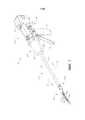
на ФИГ. 1 представлен вид в перспективе хирургического инструмента, который имеет сменный узел ствола, функционально с ним соединенный;in FIG. 1 is a perspective view of a surgical instrument having a replaceable barrel assembly functionally connected thereto;
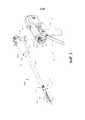
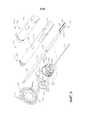
на ФИГ. 2 представлен вид в сборе с пространственным разделением компонентов сменного узла ствола и хирургического инструмента, изображенных на ФИГ. 1;in FIG. 2 is an exploded view of the components of the replacement barrel and surgical instrument assembly shown in FIG. 1;
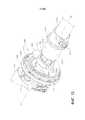
на ФИГ. 3 представлен другой вид в сборе с пространственным разделением компонентов сменного узла ствола и хирургического инструмента, изображенных на ФИГ. 1 и 2;in FIG. 3 is another exploded view of the components of the replacement barrel and surgical instrument assembly shown in FIG. 1 and 2;
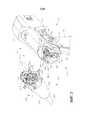
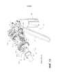
на ФИГ. 4 представлен вид в сборе с пространственным разделением компонентов части хирургического инструмента, показанного на ФИГ. 1-3;in FIG. 4 is an exploded assembled view of a portion of the surgical instrument shown in FIG. 1-3;
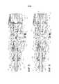
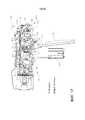
На ФИГ. 5 представлен вид сбоку в поперечном разрезе участка хирургического инструмента, изображенного на ФИГ. 4, с пусковым крючком в полностью активированном положении;FIG. 5 is a cross-sectional side view of a portion of the surgical instrument shown in FIG. 4, with the trigger in a fully activated position;
На ФИГ. 6 представлен другой вид в поперечном разрезе участка хирургического инструмента, изображенного на ФИГ. 5, с пусковым крючком в неактивированном положении;FIG. 6 is another cross-sectional view of a portion of the surgical instrument shown in FIG. 5, with the trigger in the non-activated position;
на ФИГ. 7 представлен вид в сборе с пространственным разделением одной формы сменного узла ствола;in FIG. 7 is an exploded view of one shape of a replaceable barrel assembly;
на ФИГ. 8 представлен другой вид в сборе с пространственным разделением частей сменного узла ствола, показанного на ФИГ. 7;in FIG. 8 is another exploded view of the replaceable barrel assembly shown in FIG. 7;
на ФИГ. 9 представлен другой вид в сборе с пространственным разделением частей сменного узла ствола, показанного на ФИГ. 7 и 8;in FIG. 9 is another exploded view of the replaceable barrel assembly shown in FIG. 7 and 8;
на ФИГ. 10 представлен вид в поперечном сечении части сменного узла ствола, показанного на ФИГ. 7-9;in FIG. 10 is a cross-sectional view of a portion of the replaceable barrel assembly shown in FIG. 7-9;
на ФИГ. 11 представлен вид в перспективе части узла ствола, показанного на ФИГ. 7-10, с барабаном переключателя, исключенным для ясности;in FIG. 11 is a perspective view of a portion of the barrel assembly shown in FIG. 7-10, with the switch drum excluded for clarity;
на ФИГ. 12 представлен другой вид в перспективе части сменного узла ствола, показанного на ФИГ. 11, с барабаном переключателя, установленным на нем;in FIG. 12 is another perspective view of a portion of the replaceable barrel assembly shown in FIG. 11 with a switch drum installed thereon;
на ФИГ. 13 представлен вид в перспективе части сменного узла ствола, показанного на ФИГ. 11, функционально соединенной с частью хирургического инструмента, показанного на ФИГ. 1, с его закрывающим спусковым механизмом в неактивированном положении;in FIG. 13 is a perspective view of a portion of the replaceable barrel assembly shown in FIG. 11 operatively connected to a portion of the surgical instrument shown in FIG. 1, with its closing trigger in an unactivated position;
на ФИГ. 14 представлен вид справа в вертикальной проекции сменного узла ствола и хирургического инструмента, изображенных на ФИГ. 13;in FIG. 14 is a right side elevational view of the replaceable barrel and surgical instrument assembly shown in FIG. 13;
на ФИГ. 15 представлен вид слева в вертикальной проекции сменного узла ствола и хирургического инструмента, изображенных на ФИГ. 13 и 14;in FIG. 15 is a left side elevational view of the replaceable barrel and surgical instrument assembly shown in FIG. 13 and 14;
на ФИГ. 16 представлен вид в перспективе части сменного узла ствола, показанного на ФИГ. 11, функционально соединенной с частью хирургического инструмента, показанного на ФИГ. 1, с его закрывающим спусковым механизмом в активированном положении и пусковым крючком в неактивированном положении;in FIG. 16 is a perspective view of a portion of the replaceable barrel assembly shown in FIG. 11 operatively connected to a portion of the surgical instrument shown in FIG. 1 with its closing trigger in the activated position and the trigger in the non-activated position;
на ФИГ. 17 представлен вид справа в вертикальной проекции сменного узла ствола и хирургического инструмента, изображенных на ФИГ. 16;in FIG. 17 is a right side elevational view of the replacement barrel and surgical instrument assembly shown in FIG. sixteen;
на ФИГ. 18 представлен вид слева в вертикальной проекции сменного узла ствола и хирургического инструмента, изображенных на ФИГ. 16 и 17;in FIG. 18 is a left elevation view of the replaceable barrel and surgical instrument assembly shown in FIG. 16 and 17;
на ФИГ. 18A представлен вид справа в вертикальной проекции сменного узла ствола, показанного на ФИГ. 11, функционально соединенного с частью хирургического инструмента, показанного на ФИГ. 1, с его закрывающим спусковым механизмом в активированном положении и пусковым крючком в неактивированном положении;in FIG. 18A is a right side elevational view of the replaceable barrel assembly shown in FIG. 11 operatively connected to a portion of the surgical instrument shown in FIG. 1 with its closing trigger in the activated position and the trigger in the non-activated position;
на ФИГ. 19 представлена схема системы отключения питания на электрическом разъеме рукоятки хирургического инструмента, когда узел ствола с ней не соединен;in FIG. 19 is a schematic diagram of a power cut-off system at the electrical connector of the handle of a surgical instrument when the barrel assembly is not connected to it;
на ФИГ. 20 представлен вид с пространственным разделением одного компонента концевого эффектора хирургического инструмента, изображенного на ФИГ. 1;in FIG. 20 is an exploded view of one end effector component of the surgical instrument shown in FIG. 1;
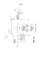
на ФИГ. 21A-21B представлена принципиальная схема цепи хирургического инструмента, показанного на ФИГ. 1, занимающая два листа графических материалов;in FIG. 21A-21B are a circuit diagram of the surgical instrument shown in FIG. 1, occupying two sheets of graphic materials;
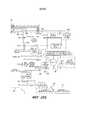
на ФИГ. 22 изображен один вариант узла питания, содержащего цепь цикла использования, выполненную с возможностью подсчета количества циклов использования батарейного блока;in FIG. 22 depicts one embodiment of a power assembly comprising a cycle of use, configured to count the number of cycles of use of a battery pack;
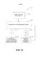
на ФИГ. 23 изображен один аспект процесса для последовательной подачи питания на сегментированную цепь;in FIG. 23 depicts one aspect of a process for sequentially energizing a segmented circuit;
на ФИГ. 24 изображен один аспект сегмента питания, содержащего множество последовательно подключенных преобразователей мощности;in FIG. 24 depicts one aspect of a power segment comprising a plurality of power converters in series;
на ФИГ. 25 изображен один аспект сегментированной цепи, выполненной с возможностью максимального увеличения подачи питания для критических и/или энергоемких функций;in FIG. 25 depicts one aspect of a segmented circuit configured to maximize power delivery for critical and / or power-hungry functions;
на ФИГ. 26 изображен один аспект системы питания, содержащей множество последовательно подключенных преобразователей мощностей, выполненных с возможностью последовательного питания;in FIG. 26 depicts one aspect of a power system comprising a plurality of series-connected power converters configured to be series-powered;
на ФИГ. 27 изображен один аспект сегментированной цепи, содержащей изолированный участок управления;in FIG. 27 depicts one aspect of a segmented circuit containing an isolated control portion;
на ФИГ. 28, которая разделена на ФИГ. 28A и 28B, представлена принципиальная схема цепи хирургического инструмента, показанного на ФИГ. 1;in FIG. 28, which is divided into FIG. 28A and 28B, a circuit diagram of the surgical instrument shown in FIG. 1;
на ФИГ. 29 представлена блок-схема хирургического инструмента, показанного на ФИГ. 1, на которой изображены интерфейсы между узлом 14 рукоятки и узлом питания, а также между узлом 14 рукоятки и сменным узлом ствола;in FIG. 29 is a block diagram of the surgical instrument shown in FIG. 1, which depicts the interfaces between the
на ФИГ. 30 представлено упрощенное изображение различных вариантов осуществления хирургического сшивающего инструмента;in FIG. 30 is a simplified illustration of various embodiments of a surgical stapling instrument;
на ФИГ. 31 представлено более подробное изображение хирургического сшивающего инструмента, показанного на ФИГ. 30, в соответствии с различными вариантами осуществления;in FIG. 31 is a more detailed view of the surgical stapling instrument shown in FIG. 30, in accordance with various embodiments;
на ФИГ. 32 представлено более подробное изображение хирургического сшивающего инструмента, показанного на ФИГ. 30, в соответствии с различными вариантами осуществления;in FIG. 32 is a more detailed view of the surgical stapling instrument shown in FIG. 30, in accordance with various embodiments;
на ФИГ. 33 представлено упрощенное изображение различных вариантов осуществления хирургического сшивающего инструмента; иin FIG. 33 is a simplified illustration of various embodiments of a surgical stapling instrument; and
на ФИГ. 34 представлено более подробное изображение хирургического сшивающего инструмента, показанного на ФИГ. 33, в соответствии с различными вариантами осуществления.in FIG. 34 is a more detailed view of the surgical stapling instrument shown in FIG. 33 in accordance with various embodiments.
Соответствующие элементы на разных видах обозначаются соответствующими условными обозначениями. Иллюстративные примеры, представленные в данном документе, демонстрируют различные варианты осуществления настоящего изобретения в одной из его форм. Эти иллюстративные примеры не должны истолковываться как ограничивающие объем изобретения.Corresponding elements in different views are denoted by corresponding symbols. The illustrative examples provided herein demonstrate various embodiments of the present invention in one of its forms. These illustrative examples should not be construed as limiting the scope of the invention.
ПОДРОБНОЕ ОПИСАНИЕDETAILED DESCRIPTION
Заявителю настоящей заявки принадлежат нижеуказанные заявки на патенты, поданные в тот же день, причем каждая из них полностью включена в настоящий документ путем ссылки:The applicant of this application owns the following patent applications filed on the same day, each of which is incorporated herein by reference in its entirety:
заявка на патент США № __________, озаглавленная SURGICAL STAPLER HAVING DOWNSTREAM CURRENT-BASED MOTOR CONTROL; досье патентного поверенного № END7660USNP/150095;US Patent Application No. __________ entitled SURGICAL STAPLER HAVING DOWNSTREAM CURRENT-BASED MOTOR CONTROL; dossier of patent attorney No. END7660USNP / 150095;
заявка на патент США № __________, озаглавленная SURGICAL STAPLER HAVING MOTOR CONTROL BASED ON A DRIVE SYSTEM COMPONENT; досье патентного поверенного № END7661USNP/150096;U.S. Patent Application No. __________ entitled SURGICAL STAPLER HAVING MOTOR CONTROL BASED ON A DRIVE SYSTEM COMPONENT; dossier of patent attorney No. END7661USNP / 150096;
заявка на патент США № __________, озаглавленная SURGICAL STAPLER HAVING TEMPERATURE-BASED MOTOR CONTROL; досье патентного поверенного № END7662USNP/150097;US Patent Application No. __________ entitled SURGICAL STAPLER HAVING TEMPERATURE-BASED MOTOR CONTROL; dossier of patent attorney No. END7662USNP / 150097;
заявка на патент США № __________, озаглавленная SURGICAL STAPLER HAVING MAGNETIC FIELD-BASED MOTOR CONTROL; досье патентного поверенного № END7663USNP/150098;US Patent Application No. __________ entitled SURGICAL STAPLER HAVING MAGNETIC FIELD-BASED MOTOR CONTROL; dossier of patent attorney No. END7663USNP / 150098;
заявка на патент США № __________, озаглавленная SURGICAL STAPLER HAVING FORCE-BASED MOTOR CONTROL; досье патентного поверенного № END7664USNP/150099; иU.S. Patent Application No. __________ entitled SURGICAL STAPLER HAVING FORCE-BASED MOTOR CONTROL; dossier of patent attorney No. END7664USNP / 150099; and
заявка на патент США № __________, озаглавленная SURGICAL STAPLER HAVING MOTOR CONTROL BASED ON AN ELECTRICAL PARAMETER RELATED TO A MOTOR CURRENT; досье патентного поверенного № END7666USNP/150101.US Patent Application No. __________ entitled SURGICAL STAPLER HAVING MOTOR CONTROL BASED ON AN ELECTRICAL PARAMETER RELATED TO A MOTOR CURRENT; dossier of patent attorney No. END7666USNP / 150101.
Заявителю настоящей заявки принадлежат представленные ниже заявки на патенты, поданные 6 марта 2015 г., каждая из которых полностью включена в настоящий документ путем ссылки:The applicant of this application owns the following patent applications filed March 6, 2015, each of which is incorporated herein by reference in its entirety:
заявка на патент США № 14/640,746, озаглавленная POWERED SURGICAL INSTRUMENT;US patent application No. 14 / 640,746 entitled POWERED SURGICAL INSTRUMENT;
заявка на патент США № 14/640,765, озаглавленная SYSTEM FOR DETECTING THE MIS-INSERTION OF A STAPLE CARTRIDGE INTO A SURGICAL STAPLER;US Patent Application No. 14 / 640,765 entitled SYSTEM FOR DETECTING THE MIS-INSERTION OF A STAPLE CARTRIDGE INTO A SURGICAL STAPLER;
заявка на патент США № 14/640,780, озаглавленная SURGICAL INSTRUMENT COMPRISING A LOCKABLE BATTERY HOUSING;U.S. Patent Application No. 14 / 640,780 entitled SURGICAL INSTRUMENT COMPRISING A LOCKABLE BATTERY HOUSING;
заявка на патент США № 14/640,795, озаглавленная MULTIPLE LEVEL THRESHOLDS TO MODIFY OPERATION OF POWERED SURGICAL INSTRUMENTS;U.S. Patent Application No. 14 / 640,795 entitled MULTIPLE LEVEL THRESHOLDS TO MODIFY OPERATION OF POWERED SURGICAL INSTRUMENTS;
заявка на патент США № 14/640,799, озаглавленная SIGNAL AND POWER COMMUNICATION SYSTEM POSITIONED ON A ROTATABLE SHAFT;U.S. Patent Application No. 14 / 640,799 entitled SIGNAL AND POWER COMMUNICATION SYSTEM POSITIONED ON A ROTATABLE SHAFT;
заявка на патент США № 14/640,817, озаглавленная INTERACTIVE FEEDBACK SYSTEM FOR POWERED SURGICAL INSTRUMENTS;US Patent Application No. 14 / 640,817 entitled INTERACTIVE FEEDBACK SYSTEM FOR POWERED SURGICAL INSTRUMENTS;
заявка на патент США № 14/640,831, озаглавленная MONITORING SPEED CONTROL AND PRECISION INCREMENTING OF MOTOR FOR POWERED SURGICAL INSTRUMENTS;US Patent Application No. 14 / 640,831 entitled MONITORING SPEED CONTROL AND PRECISION INCREMENTING OF MOTOR FOR POWERED SURGICAL INSTRUMENTS;
заявка на патент США № 14/640,832, озаглавленная ADAPTIVE TISSUE COMPRESSION TECHNIQUES TO ADJUST CLOSURE RATES FOR MULTIPLE TISSUE TYPES;US Patent Application No. 14 / 640,832 entitled ADAPTIVE TISSUE COMPRESSION TECHNIQUES TO ADJUST CLOSURE RATES FOR MULTIPLE TISSUE TYPES;
заявка на патент США № 14/640,837, озаглавленная SMART SENSORS WITH LOCAL SIGNAL PROCESSING;U.S. Patent Application No. 14 / 640,837 entitled SMART SENSORS WITH LOCAL SIGNAL PROCESSING;
заявка на патент США № 14/640,844, озаглавленная CONTROL TECHNIQUES AND SUB-PROCESSOR CONTAINED WITHIN MODULAR SHAFT WITH SELECT CONTROL PROCESSING FROM HANDLE;U.S. Patent Application No. 14 / 640,844 entitled CONTROL TECHNIQUES AND SUB-PROCESSOR CONTAINED WITHIN MODULAR SHAFT WITH SELECT CONTROL PROCESSING FROM HANDLE;
заявка на патент США № 14/640,859, озаглавленная TIME DEPENDENT EVALUATION OF SENSOR DATA TO DETERMINE STABILITY, CREEP, AND VISCOELASTIC ELEMENTS OF MEASURES; иUS Patent Application No. 14 / 640,859 entitled TIME DEPENDENT EVALUATION OF SENSOR DATA TO DETERMINE STABILITY, CREEP, AND VISCOELASTIC ELEMENTS OF MEASURES; and
заявка на патент США № 14/640,935, озаглавленная OVERLAID MULTI SENSOR RADIO FREQUENCY (RF) ELECTRODE SYSTEM TO MEASURE TISSUE COMPRESSION.US Patent Application No. 14 / 640,935 entitled OVERLAID MULTI SENSOR RADIO FREQUENCY (RF) ELECTRODE SYSTEM TO MEASURE TISSUE COMPRESSION.
Заявителю настоящей заявки принадлежат представленные ниже заявки на патенты, поданные 27 февраля 2015 г., каждая из которых полностью включена в настоящий документ путем ссылки:The applicant of this application owns the following patent applications filed February 27, 2015, each of which is incorporated herein by reference in its entirety:
заявка на патент США № 14/633,526, озаглавленная ADAPTABLE SURGICAL INSTRUMENT HANDLE;US Patent Application No. 14 / 633,526 entitled ADAPTABLE SURGICAL INSTRUMENT HANDLE;
заявка на патент США № 14/633,541, озаглавленная MODULAR STAPLING ASSEMBLY;US patent application No. 14 / 633,541 entitled MODULAR STAPLING ASSEMBLY;
заявка на патент США № 14/633,542, озаглавленная REINFORCED BATTERY FOR A SURGICAL INSTRUMENT;US patent application No. 14 / 633,542 entitled REINFORCED BATTERY FOR A SURGICAL INSTRUMENT;
заявка на патент США № 14/633,546, озаглавленная SURGICAL APPARATUS CONFIGURED TO ASSESS WHETHER A PERFORMANCE PARAMETER OF THE SURGICAL APPARATUS IS WITHIN AN ACCEPTABLE PERFORMANCE BAND;U.S. Patent Application No. 14 / 633,546 entitled SURGICAL APPARATUS CONFIGURED TO ASSESS WHETHER A PERFORMANCE PARAMETER OF THE SURGICAL APPARATUS IS WITHIN AN ACCEPTABLE PERFORMANCE BAND;
заявка на патент США № 14/633,548, озаглавленная POWER ADAPTER FOR A SURGICAL INSTRUMENT;US patent application No. 14 / 633,548 entitled POWER ADAPTER FOR A SURGICAL INSTRUMENT;
заявка на патент США № 14/633,555, озаглавленная SYSTEM FOR MONITORING WHETHER A SURGICAL INSTRUMENT NEEDS TO BE SERVICED;US Patent Application No. 14 / 633,555 entitled SYSTEM FOR MONITORING WHETHER A SURGICAL INSTRUMENT NEEDS TO BE SERVICED;
заявка на патент США № 14/633 560, озаглавленная SURGICAL CHARGING SYSTEM THAT CHARGES AND/OR CONDITIONS ONE OR MORE BATTERIES;U.S. Patent Application No. 14 / 633,560 entitled SURGICAL CHARGING SYSTEM THAT CHARGES AND / OR CONDITIONS ONE OR MORE BATTERIES;
заявка на патент США № 14/633,562, озаглавленная SURGICAL APPARATUS CONFIGURED TO TRACK AN END-OF-LIFE PARAMETER;US patent application No. 14 / 633,562 entitled SURGICAL APPARATUS CONFIGURED TO TRACK AN END-OF-LIFE PARAMETER;
заявка на патент США № 14/633,566, озаглавленная CHARGING SYSTEM THAT ENABLES EMERGENCY RESOLUTIONS FOR CHARGING A BATTERY; иU.S. Patent Application No. 14 / 633,566 entitled CHARGING SYSTEM THAT ENABLES EMERGENCY RESOLUTIONS FOR CHARGING A BATTERY; and
заявка на патент США № 14/633,576, озаглавленная SURGICAL INSTRUMENT SYSTEM COMPRISING AN INSPECTION STATION.US Patent Application No. 14 / 633,576 entitled SURGICAL INSTRUMENT SYSTEM COMPRISING AN INSPECTION STATION.
Заявителю настоящей заявки принадлежат нижеуказанные заявки на патенты, поданные 18 декабря 2014 г., каждая из которых полностью включена в настоящий документ путем ссылки:The applicant of this application owns the following patent applications, filed December 18, 2014, each of which is incorporated herein by reference in its entirety:
заявка на патент США № 14/574,478, озаглавленная SURGICAL INSTRUMENT SYSTEMS COMPRISING AN ARTICULATABLE END EFFECTOR AND MEANS FOR ADJUSTING THE FIRING STROKE OF A FIRING;U.S. Patent Application No. 14 / 574,478, entitled SURGICAL INSTRUMENT SYSTEMS COMPRISING AN ARTICULATABLE END EFFECTOR AND MEANS FOR ADJUSTING THE FIRING STROKE OF A FIRING;
заявка на патент США № 14/574,483, озаглавленная SURGICAL INSTRUMENT ASSEMBLY COMPRISING LOCKABLE SYSTEMS;US Patent Application No. 14 / 574,483 entitled SURGICAL INSTRUMENT ASSEMBLY COMPRISING LOCKABLE SYSTEMS;
заявка на патент США № 14/574,493, озаглавленная SURGICAL INSTRUMENT ASSEMBLY COMPRISING A FLEXIBLE ARTICULATION SYSTEM;US Patent Application No. 14 / 574,493 entitled SURGICAL INSTRUMENT ASSEMBLY COMPRISING A FLEXIBLE ARTICULATION SYSTEM;
заявка на патент США № 14/574,500, озаглавленная SURGICAL INSTRUMENT ASSEMBLY COMPRISING A LOCKABLE ARTICULATION SYSTEM;US Patent Application No. 14 / 574,500 entitled SURGICAL INSTRUMENT ASSEMBLY COMPRISING A LOCKABLE ARTICULATION SYSTEM;
заявка на патент США № 14/575,117, озаглавленная SURGICAL INSTRUMENTS WITH ARTICULATABLE END EFFECTORS AND MOVABLE FIRING BEAM SUPPORT ARRANGEMENTS;US Patent Application No. 14 / 575,117 entitled SURGICAL INSTRUMENTS WITH ARTICULATABLE END EFFECTORS AND MOVABLE FIRING BEAM SUPPORT ARRANGEMENTS;
заявка на патент США № 14/575,130, озаглавленная SURGICAL INSTRUMENT WITH AN ANVIL THAT IS SELECTIVELY MOVABLE ABOUT A DISCRETE NON-MOVABLE AXIS RELATIVE TO A STAPLE CARTRIDGE;US patent application No. 14 / 575,130 entitled SURGICAL INSTRUMENT WITH AN ANVIL THAT IS SELECTIVELY MOVABLE ABOUT A DISCRETE NON-MOVABLE AXIS RELATIVE TO A STAPLE CARTRIDGE;
заявка на патент США № 14/575,139, озаглавленная DRIVE ARRANGEMENTS FOR ARTICULATABLE SURGICAL INSTRUMENTS;US patent application No. 14 / 575,139 entitled DRIVE ARRANGEMENTS FOR ARTICULATABLE SURGICAL INSTRUMENTS;
заявка на патент США № 14/575,143, озаглавленная SURGICAL INSTRUMENTS WITH IMPROVED CLOSURE ARRANGEMENTS;US patent application No. 14 / 575,143 entitled SURGICAL INSTRUMENTS WITH IMPROVED CLOSURE ARRANGEMENTS;
заявка на патент США № 14/575,148, озаглавленная LOCKING ARRANGEMENTS FOR DETACHABLE SHAFT ASSEMBLIES WITH ARTICULATABLE SURGICAL END EFFECTORS; иU.S. Patent Application No. 14 / 575,148 entitled LOCKING ARRANGEMENTS FOR DETACHABLE SHAFT ASSEMBLIES WITH ARTICULATABLE SURGICAL END EFFECTORS; and
заявка на патент США № 14/575,154, озаглавленная SURGICAL INSTRUMENTS WITH ARTICULATABLE END EFFECTORS AND IMPROVED FIRING BEAM SUPPORT ARRANGEMENTS.U.S. Patent Application No. 14 / 575,154, entitled SURGICAL INSTRUMENTS WITH ARTICULATABLE END EFFECTORS AND IMPROVED FIRING BEAM SUPPORT ARRANGEMENTS.
Заявителю настоящей заявки также принадлежат нижеуказанные заявки на патенты, поданные 5 сентября 2014 г., каждая из которых полностью включена в настоящий документ путем ссылки:The applicant of this application also owns the following patent applications filed on September 5, 2014, each of which is incorporated herein by reference in its entirety:
заявка на патент США № 14/478,895, озаглавленная MULTIPLE SENSORS WITH ONE SENSOR AFFECTING A SECOND SENSOR'S OUTPUT OR INTERPRETATION;US Patent Application No. 14 / 478,895, entitled MULTIPLE SENSORS WITH ONE SENSOR AFFECTING A SECOND SENSOR'S OUTPUT OR INTERPRETATION;
заявка на патент США № 14/478,908, озаглавленная MONITORING DEVICE DEGRADATION BASED ON COMPONENT EVALUATION;US Patent Application No. 14 / 478,908 entitled MONITORING DEVICE DEGRADATION BASED ON COMPONENT EVALUATION;
заявка на патент США № 14/479,098, озаглавленная SMART CARTRIDGE WAKE UP OPERATION AND DATA RETENTION;US Patent Application No. 14 / 479,098 entitled SMART CARTRIDGE WAKE UP OPERATION AND DATA RETENTION;
заявка на патент США № 14/479,103, озаглавленная CIRCUITRY AND SENSORS FOR POWERED MEDICAL DEVICE;US patent application No. 14 / 479,103 entitled CIRCUITRY AND SENSORS FOR POWERED MEDICAL DEVICE;
заявка на патент США № 14/479,108, озаглавленная LOCAL DISPLAY OF TISSUE PARAMETER STABILIZATION;US Patent Application No. 14 / 479,108 entitled LOCAL DISPLAY OF TISSUE PARAMETER STABILIZATION;
заявка на патент США № 14/479,110, озаглавленная USE OF POLARITY OF HALL MAGNET DETECTION TO DETECT MISLOADED CARTRIDGE;US Patent Application No. 14 / 479,110 entitled USE OF POLARITY OF HALL MAGNET DETECTION TO DETECT MISLOADED CARTRIDGE;
заявка на патент США № 14/479,115, озаглавленная MULTIPLE MOTOR CONTROL FOR POWERED MEDICAL DEVICE; иUS patent application No. 14 / 479,115 entitled MULTIPLE MOTOR CONTROL FOR POWERED MEDICAL DEVICE; and
заявка на патент США № 14/479,119, озаглавленная ADJUNCT WITH INTEGRATED SENSORS TO QUANTIFY TISSUE COMPRESSION.US patent application Ser. No. 14 / 479,119 entitled ADJUNCT WITH INTEGRATED SENSORS TO QUANTIFY TISSUE COMPRESSION.
Заявителю настоящей заявки также принадлежат нижеуказанные заявки на патенты, поданные 9 апреля 2014 г., каждая из которых полностью включена в настоящий документ путем ссылки:The applicant of this application also owns the following patent applications filed on April 9, 2014, each of which is incorporated herein by reference in its entirety:
заявка на патент США № 14/248,581, озаглавленная SURGICAL INSTRUMENT COMPRISING A CLOSING DRIVE AND A FIRING DRIVE OPERATED FROM THE SAME ROTATABLE OUTPUT, в настоящее время публикация заявки на патент США № 2014/0305989;US Patent Application No. 14 / 248,581 entitled SURGICAL INSTRUMENT COMPRISING A CLOSING DRIVE AND A FIRING DRIVE OPERATED FROM THE SAME ROTATABLE OUTPUT, now US Patent Application Publication No. 2014/0305989;
заявка на патент США 14/248,584, озаглавленная MODULAR MOTOR DRIVEN SURGICAL INSTRUMENTS WITH ALIGNMENT FEATURES FOR ALIGNING ROTARY DRIVE SHAFTS WITH SURGICAL END EFFECTOR SHAFTS, в настоящее время публикация заявки на патент США № 2014/0305994;
заявка на патент США № 14/248,586, озаглавленная DRIVE SYSTEM DECOUPLING ARRANGEMENT FOR A SURGICAL INSTRUMENT, в настоящее время публикация заявки на патент США № 2014/0305990;US Patent Application No. 14 / 248,586, entitled DRIVE SYSTEM DECOUPLING ARRANGEMENT FOR A SURGICAL INSTRUMENT, currently US Patent Application Publication No. 2014/0305990;
заявка на патент США № 14/248,587, озаглавленная POWERED SURGICAL STAPLER, в настоящее время публикация заявки на патент США № 2014/0309665;US Patent Application No. 14 / 248,587, entitled POWERED SURGICAL STAPLER, currently US Patent Application Publication No. 2014/0309665;
заявка на патент США № 14/248,588, озаглавленная POWERED LINEAR SURGICAL STAPLER, в настоящее время публикация заявки на патент США № 2014/0309666;US Patent Application No. 14 / 248,588, entitled POWERED LINEAR SURGICAL STAPLER, currently US Patent Application Publication No. 2014/0309666;
заявка на патент США № 14/248,590, озаглавленная MOTOR DRIVEN SURGICAL INSTRUMENTS WITH LOCKABLE DUAL DRIVE SHAFTS, в настоящее время публикация заявки на патент США № 2014/0305987;US Patent Application No. 14 / 248,590 entitled MOTOR DRIVEN SURGICAL INSTRUMENTS WITH LOCKABLE DUAL DRIVE SHAFTS, now US Patent Application Publication No. 2014/0305987;
заявка на патент США № 14/248,591, озаглавленная TRANSMISSION ARRANGEMENT FOR A SURGICAL INSTRUMENT, в настоящее время публикация заявки на патент США № 2014/0305991;US Patent Application No. 14 / 248,591, entitled TRANSMISSION ARRANGEMENT FOR A SURGICAL INSTRUMENT, now US Patent Application Publication No. 2014/0305991;
заявка на патент США № 14/248,595, озаглавленная SURGICAL INSTRUMENT SHAFT INCLUDING SWITCHES FOR CONTROLLING THE OPERATION OF THE SURGICAL INSTRUMENT, в настоящее время публикация заявки на патент США № 2014/0305988; иUS Patent Application No. 14 / 248,595, entitled SURGICAL INSTRUMENT SHAFT INCLUDING SWITCHES FOR CONTROLLING THE OPERATION OF THE SURGICAL INSTRUMENT, currently US Patent Application Publication No. 2014/0305988; and
заявка на патент США № 14/248,607, озаглавленная MODULAR MOTOR DRIVEN SURGICAL INSTRUMENTS WITH STATUS INDICATION ARRANGEMENTS, в настоящее время публикация заявки на патент США № 2014/0305992.US Patent Application No. 14 / 248,607, entitled MODULAR MOTOR DRIVEN SURGICAL INSTRUMENTS WITH STATUS INDICATION ARRANGEMENTS, currently US Patent Application Publication No. 2014/0305992.
Заявителю настоящей заявки принадлежат нижеуказанные заявки на патенты, поданные 26 марта 2014 г., каждая из которых полностью включена в настоящий документ путем ссылки:The applicant of this application owns the following patent applications, filed March 26, 2014, each of which is incorporated herein by reference in its entirety:
заявка на патент США № 14/226,071, озаглавленная SURGICAL INSTRUMENT CONTROL CIRCUIT HAVING A SAFETY PROCESSOR;US Patent Application No. 14 / 226,071 entitled SURGICAL INSTRUMENT CONTROL CIRCUIT HAVING A SAFETY PROCESSOR;
заявка на патент США № 14/226,075, озаглавленная MODULAR POWERED SURGICAL INSTRUMENT WITH DETACHABLE SHAFT ASSEMBLIES;US Patent Application No. 14 / 226,075 entitled MODULAR POWERED SURGICAL INSTRUMENT WITH DETACHABLE SHAFT ASSEMBLIES;
заявка на патент США № 14/226,076, озаглавленная POWER MANAGEMENT THROUGH SEGMENTED CIRCUIT AND VARIABLE VOLTAGE PROTECTION;US Patent Application No. 14 / 226,076 entitled POWER MANAGEMENT THROUGH SEGMENTED CIRCUIT AND VARIABLE VOLTAGE PROTECTION;
заявка на патент США № 14/226,081, озаглавленная SYSTEMS AND METHODS FOR CONTROLLING A SEGMENTED CIRCUIT;US patent application No. 14 / 226,081 entitled SYSTEMS AND METHODS FOR CONTROLLING A SEGMENTED CIRCUIT;
заявка на патент США № 14/226,093, озаглавленная FEEDBACK ALGORITHMS FOR MANUAL BAILOUT SYSTEMS FOR SURGICAL INSTRUMENTS;U.S. Patent Application No. 14 / 226,093 entitled FEEDBACK ALGORITHMS FOR MANUAL BAILOUT SYSTEMS FOR SURGICAL INSTRUMENTS;
заявка на патент США № 14/226,094, озаглавленная VERIFICATION OF NUMBER OF BATTERY EXCHANGES/PROCEDURE COUNT;US patent application No. 14 / 226,094 entitled VERIFICATION OF NUMBER OF BATTERY EXCHANGES / PROCEDURE COUNT;
заявка на патент США № 14/226 097, озаглавленная SURGICAL INSTRUMENT COMPRISING INTERACTIVE SYSTEMS;US patent application No. 14/226 097 entitled SURGICAL INSTRUMENT COMPRISING INTERACTIVE SYSTEMS;
заявка на патент США № 14/226,099, озаглавленная STERILIZATION VERIFICATION CIRCUIT;US Patent Application No. 14 / 226,099 entitled STERILIZATION VERIFICATION CIRCUIT;
заявка на патент США № 14/226,106, озаглавленная POWER MANAGEMENT CONTROL SYSTEMS FOR SURGICAL INSTRUMENTS;US patent application No. 14 / 226,106 entitled POWER MANAGEMENT CONTROL SYSTEMS FOR SURGICAL INSTRUMENTS;
заявка на патент США № 14/226,111, озаглавленная SURGICAL STAPLING INSTRUMENT SYSTEM;US patent application No. 14 / 226,111 entitled SURGICAL STAPLING INSTRUMENT SYSTEM;
заявка на патент США № 14/226,116, озаглавленная SURGICAL INSTRUMENT UTILIZING SENSOR ADAPTATION;US patent application Ser. No. 14 / 226,116 entitled SURGICAL INSTRUMENT UTILIZING SENSOR ADAPTATION;
заявка на патент США № 14/226,117, озаглавленная POWER MANAGEMENT THROUGH SLEEP OPTIONS OF SEGMENTED CIRCUIT AND WAKE UP CONTROL;US Patent Application No. 14 / 226,117 entitled POWER MANAGEMENT THROUGH SLEEP OPTIONS OF SEGMENTED CIRCUIT AND WAKE UP CONTROL;
заявка на патент США № 14/226,125, озаглавленная SURGICAL INSTRUMENT COMPRISING A ROTATABLE SHAFT;US Patent Application No. 14 / 226,125 entitled SURGICAL INSTRUMENT COMPRISING A ROTATABLE SHAFT;
заявка на патент США № 14/226,126, озаглавленная INTERFACE SYSTEMS FOR USE WITH SURGICAL INSTRUMENTS; иU.S. Patent Application No. 14 / 226,126 entitled INTERFACE SYSTEMS FOR USE WITH SURGICAL INSTRUMENTS; and
заявка на патент США № 14/226,133, озаглавленная MODULAR SURGICAL INSTRUMENT SYSTEM.US patent application No. 14 / 226,133 entitled MODULAR SURGICAL INSTRUMENT SYSTEM.
Заявителю настоящей заявки принадлежит представленная ниже заявка на патент, поданная 7 марта 2014 г., которая полностью включена в настоящий документ путем ссылки:The applicant of this application belongs to the following patent application filed on March 7, 2014, which is fully incorporated into this document by reference:
заявка на патент США № 14/200,111, озаглавленная CONTROL SYSTEMS FOR SURGICAL INSTRUMENTS, в настоящее время публикация заявки на патент США № 2014/0263539.US Patent Application No. 14 / 200,111, entitled CONTROL SYSTEMS FOR SURGICAL INSTRUMENTS, currently US Patent Application Publication No. 2014/0263539.
Заявителю настоящей заявки также принадлежат нижеуказанные заявки на патенты, поданные 16 апреля 2013 г., каждая из которых полностью включена в настоящий документ путем ссылки:The applicant of this application also owns the following patent applications filed April 16, 2013, each of which is incorporated herein by reference in its entirety:
предварительная заявка на патент США № 61/812,365, озаглавленная SURGICAL INSTRUMENT WITH MULTIPLE FUNCTIONS PERFORMED BY A SINGLE MOTOR;US Provisional Patent Application No. 61 / 812,365 entitled SURGICAL INSTRUMENT WITH MULTIPLE FUNCTIONS PERFORMED BY A SINGLE MOTOR;
предварительная заявка на патент США № 61/812,372, озаглавленная SURGICAL INSTRUMENT WITH MULTIPLE FUNCTIONS PERFORMED BY A SINGLE MOTOR;US Provisional Patent Application No. 61 / 812,372, entitled SURGICAL INSTRUMENT WITH MULTIPLE FUNCTIONS PERFORMED BY A SINGLE MOTOR;
предварительная заявка на патент США № 61/812,376, озаглавленная LINEAR CUTTER WITH POWER;US Provisional Patent Application No. 61 / 812,376, entitled LINEAR CUTTER WITH POWER;
предварительная заявка на патент США № 61/812,382, озаглавленная LINEAR CUTTER WITH MOTOR AND PISTOL GRIP; иUS Provisional Patent Application No. 61 / 812,382 entitled LINEAR CUTTER WITH MOTOR AND PISTOL GRIP; and
предварительная заявка на патент США № 61/812,385, озаглавленная SURGICAL INSTRUMENT HANDLE WITH MULTIPLE ACTUATION MOTORS AND MOTOR CONTROL.US Provisional Patent Application No. 61 / 812,385 entitled SURGICAL INSTRUMENT HANDLE WITH MULTIPLE ACTUATION MOTORS AND MOTOR CONTROL.
Заявителю настоящей заявки также принадлежат нижеуказанные заявки на патенты, поданные 14 марта 2013 г., каждая из которых полностью включена в настоящий документ путем ссылки:The applicant of this application also owns the following patent applications filed March 14, 2013, each of which is incorporated herein by reference in its entirety:
заявка на патент США № 13/803,053, озаглавленная INTERCHANGEABLE SHAFT ASSEMBLIES FOR USE WITH A SURGICAL INSTRUMENT, в настоящее время публикация заявки на патент США № 2014/0263564;US Patent Application No. 13 / 803,053, entitled INTERCHANGEABLE SHAFT ASSEMBLIES FOR USE WITH A SURGICAL INSTRUMENT, currently US Patent Application Publication No. 2014/0263564;
заявка на патент США № 13/803,066, озаглавленная DRIVE SYSTEM LOCKOUT ARRANGEMENTS FOR MODULAR SURGICAL INSTRUMENTS, в настоящее время публикация заявки на патент США № 2014/0263565;US Patent Application No. 13 / 803,066, entitled DRIVE SYSTEM LOCKOUT ARRANGEMENTS FOR MODULAR SURGICAL INSTRUMENTS, currently US Patent Application Publication No. 2014/0263565;
заявка на патент США № 13/803,086, озаглавленная ARTICULATABLE SURGICAL INSTRUMENT COMPRISING AN ARTICULATION LOCK, в настоящее время публикация заявки на патент США № 2014/0263541;US Patent Application No. 13 / 803,086 entitled ARTICULATABLE SURGICAL INSTRUMENT COMPRISING AN ARTICULATION LOCK, currently US Patent Application Publication No. 2014/0263541;
заявка на патент США № 13/803,097, озаглавленная ARTICULATABLE SURGICAL INSTRUMENT COMPRISING A FIRING DRIVE, в настоящее время публикация заявки на патент США № 2014/0263542;US Patent Application No. 13 / 803,097 entitled ARTICULATABLE SURGICAL INSTRUMENT COMPRISING A FIRING DRIVE, currently US Patent Application Publication No. 2014/0263542;
заявка на патент США № 13/803,117, озаглавленная ARTICULATION CONTROL SYSTEM FOR ARTICULATABLE SURGICAL INSTRUMENTS, в настоящее время публикация заявки на патент США № 2014/0263553;US Patent Application No. 13 / 803,117 entitled ARTICULATION CONTROL SYSTEM FOR ARTICULATABLE SURGICAL INSTRUMENTS, currently US Patent Application Publication No. 2014/0263553;
заявка на патент США № 13/803,130, озаглавленная DRIVE TRAIN CONTROL ARRANGEMENTS FOR MODULAR SURGICAL INSTRUMENTS, в настоящее время публикация заявки на патент США № 2014/0263543;US Patent Application No. 13 / 803,130, entitled DRIVE TRAIN CONTROL ARRANGEMENTS FOR MODULAR SURGICAL INSTRUMENTS, currently US Patent Application Publication No. 2014/0263543;
заявка на патент США № 13/803,148, озаглавленная MULTI-FUNCTION MOTOR FOR A SURGICAL INSTRUMENT, в настоящее время публикация заявки на патент США № 2014/0263554;US Patent Application No. 13 / 803,148, entitled MULTI-FUNCTION MOTOR FOR A SURGICAL INSTRUMENT, currently US Patent Application Publication No. 2014/0263554;
заявка на патент США № 13/803,159, озаглавленная METHOD AND SYSTEM FOR OPERATING A SURGICAL INSTRUMENT, в настоящее время публикация заявки на патент США № 2014/0277017;US Patent Application No. 13 / 803,159, entitled METHOD AND SYSTEM FOR OPERATING A SURGICAL INSTRUMENT, now US Patent Application Publication No. 2014/0277017;
заявка на патент США № 13/803,193, озаглавленная CONTROL ARRANGEMENTS FOR A DRIVE MEMBER OF A SURGICAL INSTRUMENT, в настоящее время публикация заявки на патент США № 2014/0263537; иUS Patent Application No. 13 / 803,193 entitled CONTROL ARRANGEMENTS FOR A DRIVE MEMBER OF A SURGICAL INSTRUMENT, now US Patent Application Publication No. 2014/0263537; and
заявка на патент США № 13/803,210, озаглавленная SENSOR ARRANGEMENTS FOR ABSOLUTE POSITIONING SYSTEM FOR SURGICAL INSTRUMENTS, в настоящее время публикация заявки на патент США № 2014/0263538.US Patent Application No. 13 / 803,210 entitled SENSOR ARRANGEMENTS FOR ABSOLUTE POSITIONING SYSTEM FOR SURGICAL INSTRUMENTS, currently US Patent Application Publication No. 2014/0263538.
Заявителю настоящей заявки принадлежат представленные ниже заявки на патенты, поданные 1 марта 2013 г., каждая из которых полностью включена в настоящий документ путем ссылки:The applicant of this application owns the following patent applications filed on March 1, 2013, each of which is incorporated herein by reference in its entirety:
заявка на патент США № 13/782,295, озаглавленная Articulatable Surgical Instruments With Conductive Pathways For Signal Communication, в настоящее время публикация заявки на патент США № 2014/0246471;US Patent Application No. 13 / 782,295, entitled Articulatable Surgical Instruments With Conductive Pathways For Signal Communication, currently US Patent Application Publication No. 2014/0246471;
заявка на патент США № 13/782,323, озаглавленная Rotary Powered Articulation Joints For Surgical Instruments, в настоящее время публикация заявки на патент США № 2014/0246472;US Patent Application No. 13 / 782,323, entitled Rotary Powered Articulation Joints For Surgical Instruments, currently US Patent Application Publication No. 2014/0246472;
заявка на патент США № 13/782,338, озаглавленная Thumbwheel Switch Arrangements For Surgical Instruments, в настоящее время публикация заявки на патент США № 2014/0249557;US Patent Application No. 13 / 782,338 entitled Thumbwheel Switch Arrangements For Surgical Instruments, now US Patent Application Publication No. 2014/0249557;
заявка на патент США № 13/782,358, озаглавленная Joystick Switch Assemblies For Surgical Instruments, в настоящее время патентная публикация США № 2014/0246477;US Patent Application No. 13 / 782,358 entitled Joystick Switch Assemblies For Surgical Instruments, currently US Patent Publication No. 2014/0246477;
заявка на патент США № 13/782,375, озаглавленная Rotary Powered Surgical Instruments With Multiple Degrees of Freedom, в настоящее время публикация заявки на патент США № 2014/0246473;US Patent Application No. 13 / 782,375, entitled Rotary Powered Surgical Instruments With Multiple Degrees of Freedom, now US Patent Application Publication No. 2014/0246473;
заявка на патент США № 13/782,460, озаглавленная Multiple Processor Motor Control for Modular Surgical Instruments, в настоящее время публикация заявки на патент США № 2014/0246478;US Patent Application No. 13 / 782,460, entitled Multiple Processor Motor Control for Modular Surgical Instruments, now US Patent Application Publication No. 2014/0246478;
заявка на патент США № 13/782,481, озаглавленная Sensor Straightened End Effector During Removal Through Trocar, в настоящее время публикация заявки на патент США № 2014/0246479;US Patent Application No. 13 / 782,481, entitled Sensor Straightened End Effector During Removal Through Trocar, currently US Patent Application Publication No. 2014/0246479;
заявка на патент США № 13/782,499, озаглавленная Electromechanical Surgical Device with Signal Relay Arrangement, в настоящее время публикация заявки на патент США № 2014/0246474;US Patent Application No. 13 / 782,499 entitled Electromechanical Surgical Device with Signal Relay Arrangement, currently US Patent Application Publication No. 2014/0246474;
заявка на патент США № 13/782,518, озаглавленная Control Methods for Surgical Instruments with Removable Implement Portions, в настоящее время публикация заявки на патент США № 2014/0246475; иUS Patent Application No. 13 / 782,518 entitled Control Methods for Surgical Instruments with Removable Implement Portions, currently US Patent Application Publication No. 2014/0246475; and
заявка на патент США № 13/782,536, озаглавленная Surgical Instrument Soft Stop, в настоящее время публикация заявки на патент США № 2014/0246476.US Patent Application No. 13 / 782,536 entitled Surgical Instrument Soft Stop, currently US Patent Application Publication No. 2014/0246476.
В настоящем документе приведены подробные сведения, необходимые для понимания общей конструкции, функциональности, особенностей изготовления и применения различных вариантов осуществления, описание которых предоставлено в спецификации и проиллюстрировано сопроводительными чертежами. Хорошо известные принципы работы, компоненты и элементы не получили в настоящем документе подробного описания, чтобы не затруднять понимание вариантов осуществления, описанных в спецификации. Читатель должен понимать, что варианты осуществления, описанные и проиллюстрированные в настоящем документе, являются не имеющими ограничительного характера примерами. Следует понимать, что определенные конструктивные и функциональные особенности, описанные в данном документе, могут иметь показательный или пояснительный характер. Изменения и модификации вариантов осуществления, описанных и проиллюстрированных в данном документе, могут выполняться в пределах объема формулы изобретения.This document provides the details necessary to understand the general design, functionality, manufacturing, and application of the various embodiments described in the specification and illustrated in the accompanying drawings. The well-known principles of operation, components and elements have not been described in detail herein, so as not to obscure the understanding of the embodiments described in the specification. The reader should understand that the embodiments described and illustrated herein are non-limiting examples. It should be understood that certain structural and functional features described in this document may be indicative or explanatory in nature. Variations and modifications to the embodiments described and illustrated herein may be made within the scope of the claims.
Термины «содержать» (и любые его формы, такие как «содержит» и «содержащий»), «иметь» (и любые его формы, такие как «имеет» и «имеющий»), «включать» (и любые его формы, такие как «включает» и «включающий»), «вмещать» (и любые его формы, такие как «вмещает» и «вмещающий») представляют собой неограниченные связующие глаголы. В результате, хирургическая система или устройство, которое «содержит», «имеет», «включает» или «вмещает» один или более элементов, обладает этим одним или более элементами, но обладание не ограничивается только этим одним или более элементами. Аналогично элемент системы или устройства, который «содержит», «имеет», «включает» или «вмещает» один или более элементов, обладает этим одним или более элементами, но обладание не ограничивается только этим одним или более элементами.The terms "comprise" (and any of its forms, such as "contains" and "containing"), "have" (and any of its forms such as "has" and "having"), "include" (and any of its forms, such as "includes" and "inclusive"), "contain" (and any of its forms, such as "contains" and "containing") are unrestricted connecting verbs. As a result, a surgical system or device that “contains,” “has,” “includes,” or “contains” one or more features, possesses the one or more features, but is not limited to only that one or more features. Likewise, an element of a system or device that “contains,” “has,” “includes,” or “contains” one or more elements, possesses that one or more elements, but is not limited to only those one or more elements.
Термины «проксимальный» и «дистальный» в настоящем документе определяются относительно врача, управляющего рукояткой хирургического инструмента. Термин «проксимальный» относится к участку, расположенному ближе всего к врачу, а термин «дистальный» относится к участку, удаленному от врача. Предлагается также для удобства и ясности применительно к рисункам использовать в настоящем документе такие пространственные термины, как «вертикальный», «горизонтальный», «вверх» и «вниз». Тем не менее, поскольку использование хирургических инструментов предполагает множество ориентаций и положений, указанные термины не следует толковать как ограничивающие и (или) абсолютные.The terms "proximal" and "distal" are defined herein in relation to the physician operating the handle of the surgical instrument. The term "proximal" refers to the site closest to the physician, and the term "distal" refers to the site farthest from the physician. It is also suggested that, for convenience and clarity, spatial terms such as "vertical", "horizontal", "up" and "down" are used in this document in relation to figures. However, since the use of surgical instruments involves many orientations and positions, these terms should not be construed as limiting and / or absolute.
Для выполнения лапароскопических и минимально инвазивных хирургических вмешательств предложены различные примеры устройств и способов. Однако читателю будет вполне понятно, что различные способы и устройства, описанные в настоящем документе, можно применять в множестве хирургических вмешательств и сфер применения, включая, например, те, что связаны открытыми оперативными вмешательствами. По ходу данного подробного описания читатель сможет в еще большей мере оценить, что разнообразные инструменты, описанные в данном документе, могут быть введены в тело любым способом - как через естественные отверстия, так и через разрез или пункционное отверстие, проделанное в тканях, и т. п. Рабочая часть или насадки концевых зажимов таких инструментов могут быть введены непосредственно в тело пациента либо через устройство доступа, имеющего рабочий канал, через который можно провести концевой зажим и удлиненный ствол хирургического инструмента.Various examples of devices and methods have been proposed for performing laparoscopic and minimally invasive surgical procedures. However, the reader will be well aware that the various methods and devices described herein can be used in a variety of surgical procedures and applications, including, for example, those associated with open surgery. In the course of this detailed description, the reader will appreciate even more that the various instruments described in this document can be introduced into the body in any way - both through natural openings, and through an incision or puncture made in tissues, etc. n. The working part or attachments of the end clamps of such instruments can be inserted directly into the patient's body or through an access device having a working channel through which the end clamp and the elongated shaft of the surgical instrument can be passed.
Хирургическая сшивающая система может содержать ствол и концевой проходящий от ствола эффектор. Концевой эффектор может включать первую браншу и вторую браншу. Первая бранша содержит кассету со скобами. Кассета со скобами выполнена с возможностью вставки в первую браншу и удаления из нее; однако предусмотрены другие варианты осуществления, в которых кассета со скобами выполнена без возможности извлечения из первой бранши или, по меньшей мере, выполнена с возможностью быстрой замены из первой бранши. Вторая бранша содержит упор, выполненный с возможностью деформации скоб, выталкиваемых из кассеты со скобами. Вторая бранша выполнена с возможностью поворота относительно первой бранши вокруг оси закрытия; однако предусмотрены другие варианты осуществления, в которых первая бранша выполнена с возможностью поворота относительно второй бранши. Хирургическая сшивающая система дополнительно содержит шарнирное сочленение, выполненное с возможностью обеспечения вращения или шарнирного поворота концевого эффектора относительно ствола. Концевой эффектор выполнен с возможностью вращения вокруг оси шарнирного сочленения, проходящей через шарнирное сочленение. Предусмотрены другие варианты осуществления, которые не включают шарнирное сочленение.The surgical stapling system may comprise a stem and an end effector extending from the stem. The end effector may include a first jaw and a second jaw. The first branch contains a staple cassette. The cassette with staples is designed to be inserted into and removed from the first branch; however, other embodiments are contemplated in which the staple cartridge is non-removable from the first jaw, or at least is quick-replaceable from the first jaw. The second branch contains a stop made with the possibility of deformation of the staples ejected from the cassette with staples. The second jaw is made with the possibility of rotation relative to the first jaw about the closing axis; however, other embodiments are contemplated in which the first jaw is rotatable relative to the second jaw. The surgical stapling system further comprises a pivot joint configured to rotate or pivot the end effector relative to the shaft. The end effector is rotatable about an articulation axis passing through the articulation. Other embodiments are contemplated that do not include articulation.
Кассета со скобами содержит корпус кассеты. Корпус кассеты включает проксимальный конец, дистальный конец и платформу, проходящую между проксимальным концом и дистальным концом. В процессе применения кассета со скобами расположена на первой стороне ткани, подлежащей сшиванию, а упор расположен на второй стороне ткани. Упор перемещается к кассете со скобами для сжатия и прижимания ткани к платформе. После этого скобы, хранящиеся в корпусе кассеты с возможностью извлечения, можно размещать в ткани. Корпус кассеты включает сформированные в нем полости для скоб, при этом скобы хранятся в полостях для скоб с возможностью извлечения. Полости для скоб расположены в шесть продольных рядов. Три ряда полостей для скоб расположены на первой стороне продольного паза, и три ряда полостей для скоб расположены на второй стороне продольного паза. Возможны другие конструкции скоб и полостей для скоб.The staple cassette contains the cassette body. The cassette body includes a proximal end, a distal end, and a platform extending between the proximal end and the distal end. In use, the staple cassette is positioned on the first side of the fabric to be stitched and the abutment is positioned on the second side of the fabric. The stop moves to the cassette with staples to compress and press the fabric against the platform. Thereafter, the staples stored in the removable cassette body can be placed in the tissue. The cassette body includes staple cavities formed therein, while the staples are removably stored in the staple cavities. The staple cavities are arranged in six longitudinal rows. Three rows of staple cavities are located on the first side of the longitudinal groove and three rows of staple cavities are located on the second side of the longitudinal groove. Other designs of staples and staple cavities are possible.
В корпусе кассеты скобы поддерживаются с помощью выталкивателей скоб. Выталкиватели выполнены с возможностью перемещения между первым или неактивированным положением и вторым или активированным положением для выталкивания скоб из полостей для скоб. Выталкиватели удерживаются в корпусе кассеты с помощью фиксатора, который проходит вокруг нижней части корпуса кассеты и включает упругие элементы, выполненные с возможностью захвата корпуса кассеты и удерживания фиксатора относительно корпуса кассеты. Выталкиватели выполнены с возможностью перемещения между их неактивированными положениями и активированными положениями с помощью салазок. Салазки выполнены с возможностью перемещения между проксимальным положением, смежным с проксимальным концом, и дистальным положением, смежным с дистальным концом. Салазки содержат множество наклонных поверхностей, выполненных с возможностью скольжения под выталкивателями и подъема выталкивателей и поддерживаемых на них скоб к упору.In the cassette body, the staples are supported by staple ejectors. The ejectors are movable between a first or non-activated position and a second or activated position to push the staples out of the staple cavities. The ejectors are held in the cassette body by a retainer that extends around the lower part of the cassette body and includes elastic elements configured to grip the cassette body and hold the retainer relative to the cassette body. The ejectors are made with the possibility of moving between their non-activated positions and activated positions using a slide. The slide is movable between a proximal position adjacent to the proximal end and a distal position adjacent to the distal end. The slide contains a plurality of inclined surfaces made with the possibility of sliding under the ejectors and lifting the ejectors and the brackets supported on them against the stop.
В дополнение к указанному выше, салазки перемещаются дистально с помощью пускового элемента. Пусковой элемент выполнен с возможностью контакта с салазками и проталкивания салазок к дистальному концу. Продольный паз, сформированный в корпусе кассеты, выполнен с возможностью приема пускового элемента. Упор также включает паз, выполненный с возможностью приема пускового элемента. Пусковой элемент дополнительно содержит первый кулачок, который взаимодействует с первой браншей, и второй кулачок, который взаимодействует со второй браншей. При выдвижении пускового элемента дистально первый кулачок и второй кулачок позволяют контролировать расстояние, или тканевый зазор, между платформой кассеты со скобами и упором. Пусковой элемент также содержит скальпель, выполненный с возможностью рассечения ткани, захваченной между кассетой со скобами и упором. Желательно, по меньшей мере, частично располагать скальпель проксимально по отношению к наклонным поверхностям таким образом, чтобы скобы выталкивались раньше скальпеля.In addition to the above, the slide is moved distally by the trigger. The trigger element is adapted to contact with the slide and push the slide towards the distal end. A longitudinal groove formed in the cassette body is adapted to receive a trigger element. The stop also includes a groove adapted to receive the trigger. The trigger further comprises a first cam that interacts with the first jaws and a second cam that interacts with the second jaws. When the trigger is extended distally, the first cam and the second cam allow control of the distance, or tissue gap, between the platform of the staple cassette and the stop. The trigger also contains a scalpel capable of dissecting tissue captured between the cassette with staples and the stop. It is desirable to at least partially position the scalpel proximal to the ramped surfaces so that the staples are pushed out before the scalpel.
На ФИГ. 1-6 представлен хирургический режущий и сшивающий инструмент с двигателем 10, который может использоваться или не использоваться многократно. В показанных примерах хирургический инструмент 10 имеет корпус 12, который содержит узел 14 рукоятки, выполненный с возможностью захвата, манипулирования и активирования врачом. Корпус 12 выполнен с возможностью функционального прикрепления к сменному узлу 200 ствола, который имеет концевой эффектор 300, функционально соединенный с ним, который выполнен с возможностью выполнения одной или более хирургических задач или процедур. По мере изучения настоящего подробного описания будет понятно, что различные уникальные и инновационные механизмы различных форм сменных узлов ствола, раскрытые в настоящем документе, также могут эффективно применяться в связи с хирургическими системами с роботизированным управлением. Таким образом, термин «корпус» также может охватывать корпус или аналогичную часть роботизированной системы, которая вмещает или иным образом функционально поддерживает по меньшей мере одну приводную систему, выполненную с возможностью генерирования и применения по меньшей мере одного управляющего движения, которое может применяться для приведения в действие сменных узлов ствола, описанных в настоящем документе, и их соответствующих эквивалентов. Термин «рама» может относиться к участку ручного хирургического инструмента. Термин «рама» также может представлять собой часть хирургического инструмента с роботизированным управлением и/или часть роботизированной системы, которая может применяться для функционального управления хирургическим инструментом. Например, сменные узлы стержней, описанные в настоящем документе, могут применяться с различными роботизированными системами, инструментами, компонентами и способами, изложенными в заявке на патент США № 13/118,241, озаглавленной SURGICAL STAPLING INSTRUMENTS WITH ROTATABLE STAPLE DEPLOYMENT ARRANGEMENTS, в настоящее время публикация заявки на патент США № 9 072 535. Заявка на патент США № 13/118,241, озаглавленная SURGICAL STAPLING INSTRUMENTS WITH ROTATABLE STAPLE DEPLOYMENT ARRANGEMENTS, в настоящее время патент США № 9, 072, 535, полностью включена в настоящий документ путем ссылки.FIG. 1-6 show a surgical cutting and stapling instrument with a
Корпус 12, представленный на ФИГ. 1-3, показан в соединении со сменным узлом 200 ствола, который имеет концевой эффектор 300, содержащий хирургическое режущее и сшивающее устройство, которое выполнено с возможностью функциональной поддержки в нем кассеты 304 со скобами. Корпус 12 может быть выполнен с возможностью использования со сменными узлами стержней, которые имеют концевые эффекторы, приспособленные для поддерживания кассет со скобами различных размеров и типов, и обладают разной длиной ствола, размером, типом и т. д. Кроме того, корпус 12 можно эффективно применять с различными сменными узлами стержней, включая те узлы, которые выполнены с возможностью приложения других движений и форм энергии, таких как, например, радиочастотная (РЧ) энергия, ультразвуковая энергия и/или движение, в виде конструкций концевых эффекторов, адаптированных для использования в различных сферах применения и процедурах. Более того, в концевых эффекторах, узлах ствола, рукоятках, хирургических инструментах и/или системах хирургических инструментов для фиксации ткани может использоваться любой подходящий крепежный элемент или крепежные элементы. Например, кассета с крепежными элементами, содержащая множество хранящиеся в ней с возможностью извлечения крепежных элементов, может съемно вводиться и/или прикрепляться к концевому эффектору узла ствола.The
На ФИГ. 1 показан хирургический инструмент 10 с функционально соединенным с ним сменным узлом 200 ствола. На ФИГ. 2 и 3 изображено крепление сменного узла 200 ствола к корпусу 12 или узлу 14 рукоятки. Как показано на ФИГ. 4, узел 14 рукоятки может содержать пару взаимно соединенных корпусных сегментов 16 и 18 ручки, которые могут быть соединены винтами, защелками, клеем и т. п. В показанной конструкции корпусные сегменты 16 и 18 ручки в совокупности образуют участок 19 пистолетной рукоятки, которую можно захватывать рукой и которой может манипулировать врач. Как будет дополнительно более подробно описано ниже, узел 14 рукоятки функционально поддерживает в себе множество приводных систем, которые выполнены с возможностью генерирования и приложения различных управляющих движений к соответствующим частям сменного узла ствола, к которому эти системы функционально прикреплены.FIG. 1 shows a
Как показано на ФИГ. 4, узел 14 рукоятки может дополнительно включать в себя раму 20, функционально поддерживающую множество приводных систем. Например, рама 20 может функционально поддерживать первую систему, или систему закрывающего привода, по существу обозначенную как элемент 30, которая может быть реализована для приложения закрывающих и открывающих движений к сменному узлу 200 ствола, который функционально соединен с ним или прикреплен к нему. В по меньшей мере одной форме система 30 закрывающего привода может включать в себя исполнительный механизм в форме закрывающего спускового механизма 32, который вращательно поддерживается рамой 20. В частности, как показано на ФИГ. 4, закрывающий спусковой механизм 32 связан с возможностью поворота с корпусом 14 с помощью штифта 33. Такая конструкция позволяет врачу манипулировать закрывающим спусковым механизмом 32 так, что, когда врач захватывает участок пистолетной рукоятки 19 узла 14 рукоятки, закрывающий спусковой механизм 32 может быть легко повернут из исходного, или неактивированного, положения в активированное положение, а более конкретно - в полностью нажатое или полностью активированное положение. Закрывающий спусковой механизм 32 может быть смещен в неактивированное положение с помощью пружины или другого смещающего механизма (не показан). В различных формах система закрывающего привода 30 дополнительно включает в себя узел 34 закрывающего звена, который вращательно соединен с закрывающим спусковым механизмом 32. Как показано на ФИГ. 4, узел 34 закрывающего звена может иметь первое закрывающее звено 36 и второе закрывающее звено 38, которые шарнирно соединены с закрывающим спусковым механизмом 32 штифтом 35. Второе закрывающее звено 38 также в настоящем документе может называться крепежным элементом и иметь поперечный крепежный штифт 37.As shown in FIG. 4, the
Как показано на ФИГ. 4, на первом закрывающем звене 36 может присутствовать блокирующая стенка или конец 39, выполненные с возможностью совместной работы с узлом 60 высвобождения закрывающего механизма, связанным с рамой 20 с возможностью поворота. В по меньшей мере одной форме узел 60 высвобождения закрывающего механизма может содержать узел 62 кнопки высвобождения, на котором присутствует выступающая дистально блокирующая собачка 64. Узел кнопки высвобождения 62 может вращаться в направлении против часовой стрелки с помощью пружины высвобождения (не показана). Когда врач нажимает на закрывающий спусковой механизм 32 и выводит его из неактивированного положения к участку пистолетной рукоятки 19 узла 14 рукоятки, первое закрывающее звено 36 вращается вверх до точки, в которой блокирующая собачка 64 входит в удерживающее зацепление с блокирующей стенкой 39 на первом закрывающем звене 36, посредством этого не позволяя закрывающему спусковому механизму 32 вернуться в неактивированное положение. См. ФИГ. 18. Таким образом, узел высвобождения закрывающего механизма 60 служит для блокировки закрывающего спускового механизма 32 в полностью активированном положении. Когда врачу нужно разблокировать закрывающий спусковой механизм 32, чтобы он смог сместиться в неактивированное положение, врач просто вращает узел 62 кнопки высвобождения закрывающего механизма так, чтобы блокирующая собачка 64 вышла из зацепления с блокирующей стенкой 39 на первом закрывающем звене 36. После того как блокирующая собачка 64 вышла из зацепления с первым закрывающим звеном 36, закрывающий спусковой механизм 32 может вращаться назад в неактивированное положение. Также возможна реализация других блокирующих и высвобождающих механизмов закрывающего спускового механизма.As shown in FIG. 4, the
В дополнение к приведенному выше, на ФИГ. 13-15 показан закрывающий спусковой механизм 32 в своем неактивированном положении, которое связано с открытым, или разжатым, положением узла 200 ствола, в котором ткань может быть расположена между браншами узла 200 ствола. На ФИГ. 16-18 показан закрывающий спусковой механизм 32 в своем активированном положении, которое связано с закрытым или сжатым положением узла 200 ствола, в котором ткань зажата между браншами узла 200 ствола. При сравнении ФИГ. 14 и 17, читателю будет понятно, что, когда закрывающий спусковой механизм 32 перемещается из неактивированного положения (ФИГ. 14) в активированное положение (ФИГ. 17), кнопка 62 высвобождения закрывающего механизма поворачивается между первым положением (ФИГ. 14) и вторым положением (ФИГ. 17). Поворот кнопки 62 высвобождения закрывающего механизма можно назвать поворотом вверх; однако по меньшей мере часть кнопки 62 высвобождения закрывающего механизма поворачивается к печатной плате 100. Как показано на ФИГ. 4, кнопка 62 высвобождения закрывающего механизма может включать в себя проходящее от нее ответвление 61 и магнитный элемент 63, такой как, например, постоянный магнит, установленный на ответвлении 61. Когда кнопка 62 высвобождения закрывающего механизма поворачивается из своего первого положение во второе положение, магнитный элемент 63 может перемещаться к печатной плате 100. Печатная плата 100 может включать в себя по меньшей мере один датчик, выполненный с возможностью определения перемещения магнитного элемента 63. В по меньшей мере одном аспекте на нижнюю поверхность печатной платы 100 может быть установлен, например, датчик 65 магнитного поля. Датчик 65 магнитного поля может быть выполнен с возможностью определения изменения магнитного поля, окружающего датчик 65 магнитного поля, вызванного перемещением магнитного элемента 63. Датчик 65 магнитного поля может, например, обмениваться сигналами с микроконтроллером 1500 (ФИГ. 19), который может определять, находится ли кнопка 62 высвобождения закрывающего механизма в первом положении, которое связано с неактивированным положением закрывающего спускового механизма 32 и открытой конфигурацией концевого эффектора, во втором положении, которое связано с активированным положением закрывающего спускового механизма 32 и закрытой конфигурацией концевого эффектора, и/или в любом положении между первым и вторым положением.In addition to the above, in FIG. 13-15 show the
В рамках настоящего описания датчик магнитного поля может представлять собой, помимо прочего, датчик Холла, индукционную катушку, магнитный датчик с оптической накачкой, ядерную прецессию, сверхпроводящий магнитометр (SQUID), эффект Холла, анизотропное магнитосопротивление, гигантское магнитосопротивление, магнитные туннельные переходы, гигантский магнитоимпеданс, магнитострикционные/пьезоэлектрические композиты, магнитодиод, магнитотранзистор, оптоволокно, магнитооптические датчики и магнитные датчики на основе микроэлектромеханических систем.As used herein, a magnetic field sensor may be, but is not limited to, a Hall sensor, an induction coil, an optically pumped magnetic sensor, nuclear precession, a superconducting magnetometer (SQUID), a Hall effect, anisotropic magnetoresistance, giant magnetoresistance, magnetic tunnel junctions, giant magnetoimpedance , magnetostrictive / piezoelectric composites, magnetodiode, magnetotransistor, optical fiber, magneto-optical sensors and magnetic sensors based on microelectromechanical systems.
По меньшей мере, в одной форме узел 14 рукоятки и рама 20 могут функционально поддерживать другую приводную систему, которая в настоящем документе называется системой 80 пускового привода, выполненную с возможностью приложения пусковых движений к соответствующим участкам прикрепленного к нему сменного узла ствола. В настоящем документе система 80 пускового привода также может называться второй приводной системой. В системе 80 пускового привода может применяться электрический двигатель 82, который размещен в участке 19 пистолетной рукоятки узла 14 рукоятки. В различных формах двигатель 82 может представлять собой приводной щеточный двигатель постоянного тока с максимальной скоростью поворота, например, приблизительно 25 000 оборотов в минуту. В других конструкциях двигатель 82 может представлять собой бесщеточный двигатель, беспроводной двигатель, синхронный двигатель, шаговый двигатель или любой другой подходящий электрический двигатель. Двигатель 82 может получать электропитание от источника питания 90, который в одной форме может содержать съемный блок питания 92. Как показано, например, на ФИГ. 4, блок питания 92 может содержать проксимальный участок 94 корпуса, который выполнен с возможностью крепления к дистальному участку 96 корпуса. Проксимальный участок 94 корпуса и дистальный участок 96 корпуса выполнены с возможностью функциональной поддерживания в них множества батарей 98. Каждая батарея 98 может представлять собой, например, литий-ионную («LI») или другую подходящую батарею. Дистальный участок 96 корпуса выполнен с возможностью съемного функционального крепления к узлу 100 управляющей печатной платы, который также функционально связан с двигателем 82. В качестве источника питания хирургического инструмента 10 может применяться ряд последовательно соединенных батарей 98. Кроме того, блок питания 90 может быть сменным и/или перезаряжаемым.In at least one form, the
Как кратко описано выше в отношении различных других форм, электрический двигатель 82 может включать в себя поворачиваемый стержень (не показан), функционально стыкующийся с узлом зубчатого редуктора 84, который монтируется так, что находится в сцепленном зацеплении с набором или рейкой приводных зубцов 122 на выполненном с возможностью продольного перемещения приводном элементе 120. В процессе применения полярность напряжения, обеспечиваемая источником 90 питания, позволяет электрическому двигателю 82 вращаться в направлении по часовой стрелке, причем полярность напряжения, приложенную к электрическому двигателю батареей, можно изменить на обратную для работы электрического двигателя 82 в направлении против часовой стрелки. Когда электрический двигатель 82 поворачивается в одном направлении, приводной элемент 120 будет приводиться в движение в дистальном направлении DD по оси. При приведении двигателя 82 в движение в противоположном направлении вращения приводной элемент 120 будет приводиться в движение по оси в проксимальном направлении PD. Узел 14 рукоятки может иметь переключатель, который может быть выполнен с возможностью изменения на обратную полярности, прилагаемой к электродвигателю 82 блоком питания 90. Как и в других формах, описанных в настоящем документе, узел 14 рукоятки также может включать в себя датчик, выполненный с возможностью обнаружения положения приводного элемента 120 и/или направления, в котором перемещается приводной элемент 120.As briefly described above with respect to various other forms, the
Активацией двигателя 82 можно управлять с помощью пускового крючка 130, вращательно поддерживаемого на узле 14 рукоятки. Пусковой крючок 130 можно вращать между неактивированным положением и активированным положением. Пусковой крючок 130 может смещаться в неактивированное положение с помощью пружины 132 или другого смещающего механизма так, что, когда врач высвобождает пусковой крючок 130, его можно вращать или иным образом возвращать в неактивированное положение с помощью пружины 132 или смещающего механизма. По меньшей мере, в одной форме пусковой крючок 130 может быть расположен на удалении от закрывающего спускового механизма 32, как было описано выше. По меньшей мере, в одной форме к закрывающему спусковому механизму 32 может монтироваться кнопка предохранителя пускового крючка 134 с помощью штифта 35 с возможностью поворота. Кнопка 134 предохранителя может быть расположена между пусковым крючком 130 и закрывающим спусковым механизмом 32 и иметь выступающее поворотное плечо 136. См. ФИГ. 4. Когда закрывающий спусковой механизм 32 находится в неактивированном положении, кнопка 134 предохранителя содержится в узле 14 рукоятки, где врач не может получить к ней простой доступ и переместить ее между безопасным положением, предотвращающим активацию пускового крючка 130, и пусковым положением, в котором пусковой крючок 130 может быть нажат. Когда врач нажимает на закрывающий спусковой механизм 32, кнопка предохранителя 134 и пусковой крючок 130 вращаются вниз, и в этом положении врач может манипулировать ими.Activation of the
Как описано выше, узел 14 рукоятки может включать в себя закрывающий спусковой механизм 32 и пусковой крючок 130. Как показано на ФИГ. 14-18A, пусковой крючок 130 может быть установлен с возможностью поворота на закрывающем спусковом механизме 32. Закрывающий спусковой механизм 32 может содержать проходящее от него ответвление 31 и пусковой крючок 130 может быть установлен на ответвлении 31 с возможностью поворота относительно поворотного штифта 33. Когда закрывающий спусковой механизм 32 перемещается из неактивированного положения (ФИГ. 14) в активированное положение (ФИГ. 17), пусковой крючок 130 может опускаться вниз, как кратко описано выше. После перемещения кнопки 134 предохранителя в пусковое положение, как показано на ФИГ. 18A, можно нажать пусковой крючок 130 для приведения в действие двигателя пусковой системы хирургического инструмента. В различных случаях узел 14 рукоятки может включать в себя систему слежения, такую как, например, система 800, выполненную с возможностью определения положения закрывающего спускового механизма 32 и/или положения пускового крючка 130. Как главным образом показано на ФИГ. 14, 17 и 18A, система 800 слежения может содержать магнитный элемент, такой как постоянный магнит 802, например, который установлен на ответвлении 801, проходящем от пускового крючка 130. Система 800 слежения может содержать один или более датчиков, например, таких как первый датчик 803 магнитного поля и второй датчик 804 магнитного поля, которые могут быть выполнены с возможностью отслеживания положения магнита 802.As described above, the
При сравнении ФИГ. 14 и 17, читателю будет понятно, что, когда закрывающий спусковой механизм 32 перемещается из неактивированного положения в активированное положение, магнит 802 может перемещаться между первым положением рядом с первым датчиком 803 магнитного поля и вторым положением рядом со вторым датчиком 804 магнитного поля.When comparing FIG. 14 and 17, the reader will appreciate that when the
При сравнении ФИГ. 17 и 18A, читателю также будет понятно, что, когда пусковой крючок 130 перемещается из неактивированного положения (ФИГ. 17) в активированное положение (ФИГ. 18A), магнит 802 может перемещаться относительно второго датчика 804 магнитного поля. Датчики 803 и 804 могут отслеживать перемещение магнита 802 и могут обмениваться сигналами с микроконтроллером на печатной плате 100. За счет использования данных от первого датчика 803 и/или второго датчика 804, микроконтроллер может определять положение магнита 802 вдоль заданного пути, и, на основании этого положения, микроконтроллер может определять, находится закрывающий спусковой механизм 32 в неактивированном положении, активированном положении или промежуточном положении. Аналогично, за счет использования данных от первого датчика 803 и/или второго датчика 804, микроконтроллер может определять положение магнита 802 вдоль заданного пути, и, на основании этого положения, микроконтроллер может определять, находится закрывающий спусковой механизм 130 в неактивированном положении, полностью активированном положении или промежуточном положении.When comparing FIG. 17 and 18A, the reader will also appreciate that when the firing
Как указано выше, по меньшей мере, в одной форме выполненный с возможностью продольного перемещения приводной элемент 120 имеет рейку образованных на нем зубцов 122 для сцепленного зацепления с соответствующей приводной шестерней 86 узла зубчатого редуктора 84. По меньшей мере одна форма также включает в себя приводимый в действие вручную аварийный узел 140, выполненный с возможностью того, чтобы врач мог вручную втягивать приводной элемент 120, выполненный с возможностью продольного перемещения, если двигатель 82 становится недоступен. Аварийный узел 140 может включать в себя узел рычага или аварийной рукоятки 142, выполненный с возможностью ручного вращения в храповое зацепление с зубцами 124 приводного элемента 120. Таким образом, врач может вручную оттянуть приводной элемент 120 с помощью узла аварийной рукоятки 142, чтобы передвинуть приводной элемент 120 с помощью храпового механизма в проксимальном направлении PD. В публикации заявки на патент США № 2010/0089970, в настоящее время патент США № 8,608,045, описаны аварийные механизмы и другие компоненты, механизмы и системы, которые также могут применяться с различными инструментами, описанными в настоящем документе. Заявка на патент США с серийным № 12/249,117, озаглавленная POWERED SURGICAL CUTTING AND STAPLING APPARATUS WITH MANUALLY RETRACTABLE FIRING SYSTEM, публикация заявки на патент США № 2010/0089970, теперь патент США № 8,608,045, которая полностью включена в настоящий документ путем ссылки.As indicated above, in at least one shape, the longitudinally
Как показано на ФИГ. 1 и 7, сменный узел 200 ствола имеет хирургический концевой эффектор 300, который содержит удлиненный канал 302, который выполнен с возможностью функциональной поддержки в нем кассеты 304 со скобами. Концевой эффектор 300 может дополнительно включать в себя упор 306, поддерживаемый с возможностью поворота относительно удлиненного канала 302. Сменный узел 200 ствола может дополнительно содержать шарнирное сочленение 270 и фиксатор 350 шарнира (ФИГ. 8), который может быть выполнен с возможностью разъемного удержания концевого эффектора 300 в требуемом положении относительно оси ствола SA-SA. Подробное описание конструкции и работы концевого эффектора 300, шарнирного сочленения 270 и фиксатора 350 шарнира представлено в заявке на патент США № 13/803,086, поданной 14 марта 2013 г., озаглавленной ARTICULATABLE SURGICAL INSTRUMENT COMPRISING AN ARTICULATION LOCK, в настоящее время - публикация заявки на патент США № 2014/0263541. Полное описание заявки на патент США № 13/803,086, поданной 14 марта 2013 г., озаглавленной ARTICULATABLE SURGICAL INSTRUMENT COMPRISING AN ARTICULATION LOCK, в настоящее время - публикация заявки на патент США № 2014/0263541, включено в настоящий документ путем ссылки. Как показано на ФИГ. 7 и 8, сменный узел 200 ствола может дополнительно содержать проксимальный корпус, или конус 201, состоящий из участков 202 и 203 конуса. Сменный узел 200 ствола может дополнительно иметь закрывающую трубку 260, которая может использоваться для закрытия и/или открытия упора 306 концевого эффектора 300. Как показано преимущественно на ФИГ. 8 и 9, узел 200 ствола может включать в себя цапфу 210, которая может быть выполнена с возможностью неподвижной поддержки участка 212 рамы ствола и фиксирующего элемента 350 шарнирного сочленения. См. ФИГ. 8. Цапфа 210 может быть выполнена с возможностью, во-первых, скользящей поддержки пускового элемента 220 в ней, а, во-вторых, скользящей поддержки закрывающей трубки 260, которая проходит вокруг цапфы 210. Цапфа 210 также может быть выполнена с возможностью скользящей поддержки проксимального шкива шарнира 230. Приводной элемент 230 шарнирного сочленения имеет дистальный конец 231, который выполнен с возможностью функционального взаимодействия с фиксирующим элементом 350 шарнирного сочленения. Фиксирующий элемент 350 шарнирного сочленения сопрягается с шарнирной рамой 352, которая выполнена с возможностью функционального взаимодействия с направляющим штифтом (не показан) рамы концевого эффектора (не показана). Как указано выше, дополнительная информация, касающаяся работы фиксирующего элемента 350 шарнирного сочленения и шарнирной рамы, содержится в заявке на патент США № 13/803,086, в настоящее время - публикация заявки на патент США № 2014/0263541. В различных случаях цапфа 210 может содержать проксимальный конец 211, который поддерживается с возможностью поворота на шасси 240. Например, в одной конструкции проксимальный конец 211 цапфы 210 имеет резьбу 214, выполненную на ней для резьбового крепления к опоре 216 цапфы, выполненной с возможностью поддержки на шасси 240. См. ФИГ. 7. Такая конструкция облегчает вращающееся крепление цапфы 210 к шасси 240 таким образом, что цапфа 210 может избирательно поворачиваться вокруг оси SA-SA ствола относительно шасси 240.As shown in FIG. 1 and 7, the
Как показано преимущественно на ФИГ. 7, сменный узел 200 ствола имеет закрывающий челнок 250, который скользящим образом поддерживается в шасси 240 так, что он может перемещаться в осевом направлении относительно него. Как показано на ФИГ. 3 и 7, закрывающий челнок 250 включает в себя пару проксимально выступающих крюков 252, которые выполнены с возможностью крепления к крепежному штифту 37, который присоединен ко второму закрывающему звену 38, как дополнительно будет более подробно описано ниже. Проксимальный конец 261 закрывающей трубки 260 связан с закрывающим челноком 250 для вращения относительно него. Например, U-образный соединитель 263 вставляется в кольцевой паз 262 в проксимальном конце 261 закрывающей трубки 260 и фиксируется внутри вертикальных пазов 253 в закрывающем челноке 250. См. ФИГ. 7. Такая конструкция служит для крепления закрывающей трубки 260 к закрывающему челноку 250 для осевого перемещения с ним, при этом позволяя закрывающей трубке 260 поворачиваться относительно закрывающего челнока 250 вокруг оси SA-SA ствола. Закрывающая пружина 268 опирается на закрывающую трубку 260 и служит для смещения закрывающей трубки 260 в проксимальном направлении PD, которое может служить для поворачивания закрывающего спускового механизма в неактивированное положение, когда узел ствола функционально соединяется с узлом 14 рукоятки.As shown predominantly in FIG. 7, the
В по меньшей мере одной форме сменный узел 200 ствола дополнительно может включать в себя шарнирное сочленение 270. Однако другие сменные узлы ствола могут не осуществлять шарнирный поворот. Как показано на ФИГ. 7, например, шарнирное сочленение 270 включает в себя узел двухшарнирной закрывающей гильзы 271. В соответствии с различными формами узел двухшарнирной закрывающей гильзы 271 включает в себя узел закрывающей гильзы 272 концевого эффектора, который имеет дистально выступающие верхний и нижний хвостовики 273, 274. Узел закрывающей гильзы 272 концевого эффектора включает в себя подковообразное отверстие 275 и язычок 276 для зацепления с открывающим язычком на упоре 306 различными способами, описанными в заявке на патент США № 13/803,086, поданной 14 марта 2013 г., озаглавленной ARTICULATABLE SURGICAL INSTRUMENT COMPRISING AN ARTICULATION LOCK, в настоящее время публикация заявки на патент США № 2014/0263541, которая полностью включена в настоящий документ путем ссылки. Как более подробно описано в этом документе, подковообразное отверстие 275 и язычок 276 зацепляются с язычком на упоре, когда упор 306 открыт. Верхнее двухшарнирное звено 277 включает в себя выступающие вверх дистальный и проксимальный поворотные штифты, которые зацепляются соответственно с верхним дистальным отверстием для штифта в верхнем проксимально выступающем хвостовике 273 и с верхним проксимальным отверстием для штифта в верхнем дистально выступающем хвостовике 264 на закрывающей трубке 260. Нижнее двухшарнирное звено 278 включает в себя выступающие вверх дистальный и проксимальный шарнирные штифты, которые зацепляются соответственно с нижним дистальным штифтовым отверстием в нижнем проксимально выступающем хвостовике 274 и с нижним проксимальным штифтовым отверстием в нижнем дистально выступающем хвостовике 265. См. также ФИГ. 8.In at least one form,
В процессе применения закрывающая трубка 260 поступательно перемещается дистально (в направлении DD) для закрытия упора 306, например, в ответ на приведение в действие закрывающего спускового механизма 32. Упор 306 закрывается путем поступательного перемещения дистально закрывающей трубки 260 и, таким образом, узла закрывающей гильзы ствола 272, в результате чего он ударяется о проксимальную поверхность упора 360 способом, описанным в указанной выше путем ссылки заявке на патент США № 13/803,086, в настоящее время - публикация заявки на патент США № 2014/0263541. Как было подробно описано в этой ссылке, упор 306 открывается путем поступательного перемещения проксимально закрывающей трубки 260 и узла закрывающей гильзы ствола 272, в результате чего язычок 276 и подковообразное отверстие 275 входят в контакт с язычком упора и толкают его, поднимая упор 306. В положении с открытым упором закрывающая трубка ствола 260 перемещается в проксимальное положение.During use, the
Как указано выше, хирургический инструмент 10 может дополнительно содержать фиксирующий элемент 350 шарнирного сочленения типов и конструкции, описанной подробнее в заявке на патент США № 13/803,086, в настоящее время - публикация заявки на патент США № 2014/0263541, который может быть выполнен с возможностью и может работать так, чтобы обеспечивать избирательную блокировку концевого эффектора 300 в положении. Такие конструкции позволяют вращать или шарнирно поворачивать концевой эффектор 300 относительно закрывающей трубки 260 ствола, когда фиксирующий элемент 350 шарнирного сочленения находится в его незаблокированном состоянии. В таком незаблокированном состоянии концевой эффектор 300 может быть расположен и прижат к мягкой ткани и/или кости, например, окружающей операционное поле внутри организма пациента, в результате чего концевой эффектор 300 может шарнирно поворачиваться относительно закрывающей трубки 260. Концевой эффектор 300 также может шарнирно поворачиваться относительно закрывающей трубки 260 посредством приводного элемента шарнирного сочленения 230.As noted above, the
Как также указано выше, сменный узел 200 ствола дополнительно включает в себя пусковой элемент 220, поддерживаемый для осевого перемещения внутри цапфы 210 ствола. Пусковой элемент 220 включает в себя участок 222 промежуточного пускового ствола, выполненный с возможностью прикрепления к дистальному режущему участку или режущему полотну 280. Также в настоящем документе пусковой элемент 220 может называться «вторым узлом» и/или «вторым узлом ствола». Как может быть показано на ФИГ. 8 и 9, промежуточная часть пускового ствола 222 может включать в себя продольную прорезь 223 в ее дистальном конце, которая может быть выполнена с возможностью принимать язычок 284 на проксимальном конце 282 дистального режущего полотна 280. Продольный паз 223 и проксимальный конец 282 могут быть выполнены по форме и размеру таким образом, чтобы обеспечивать относительное перемещение между ними, и могут содержать скользящее сочленение 286. Скользящее сочленение 286 может обеспечивать перемещение промежуточного участка 222 пускового ствола пускового привода 220 для перемещения так, чтобы обеспечить шарнирный поворот концевого эффектора 300 без перемещения или по меньшей мере по существу без перемещения дистальной пусковой штанги 280. После достижения надлежащей ориентации концевого эффектора 300, участок 222 промежуточного пускового ствола можно перемещать дистально, пока проксимальная боковая стенка продольной прорези 223 не войдет в контакт с язычком 284 для продвижения режущего полотна 280 и активации кассеты со скобами, размещенной в канале 302. Как показано на ФИГ. 8 и 9, цапфа 210 ствола содержит удлиненное отверстие или окно 213, упрощающее сборку и вставку промежуточного участка пускового ствола 222 в раму 210 стержня. После вставки промежуточного участка 222 пускового ствола верхний сегмент 215 рамы может зацепляться с рамой 212 ствола, заключая в нее участок 222 промежуточного пускового ствола и режущее полотно 280. Дополнительное описание работы пускового элемента 220 приведено в заявке на патент США № 13/803,086, в настоящее время публикация заявки на патент США № 2014/0263541.As also noted above, the
В дополнение к указанному выше, узел 200 ствола может включать в себя узел сцепления 400, который может быть выполнен с возможностью избирательного и высвобождаемого соединения приводного элемента 230 шарнирного сочленения и пускового элемента 220. В одной форме узел 400 сцепления включает в себя фиксирующее кольцо, или гильзу, 402, расположенное вокруг пускового элемента 220, причем фиксирующая гильза 402 может поворачиваться между зацепленным положением, в котором фиксирующая гильза 402 соединяет приводной элемент 360 шарнирного сочленения с пусковым элементом 220, и расцепленным положением, в котором приводной элемент 360 шарнирного сочленения не связан функционально с пусковым элементом 200. Когда фиксирующая гильза 402 находится в ее зацепленном положении, дистальное перемещение пускового элемента 220 может перемещать приводной элемент 360 шарнирного сочленения дистально, и, соответственно, проксимальное перемещение пускового элемента 220 может перемещать приводной элемент 230 шарнирного сочленения проксимально. Когда фиксирующая гильза 402 находится в ее расцепленном положении, перемещение пускового элемента 220 не передается на приводной элемент 230 шарнирного сочленения, в результате чего пусковой элемент 220 может перемещаться независимо от приводного элемента 230 шарнирного сочленения. В различных обстоятельствах приводной элемент 230 шарнирного сочленения может удерживаться в положении с помощью фиксирующего элемента 350 шарнирного сочленения, когда приводной элемент 230 шарнирного сочленения не перемещается в проксимальное или дистальное направления с помощью пускового элемента 220.In addition to the above, the
Как показано преимущественно на РИС. 9, гильза блокировки 402 может содержать цилиндрический или по меньшей мере по существу цилиндрический корпус, включающий продольное отверстие 403, образованное с возможностью принимать пусковой элемент 220. Фиксирующая гильза 402 может содержать обращенные диаметрально внутрь фиксирующие выступы 404 и обращенный наружу фиксирующий элемент 406. Фиксирующие выступы 404 могут быть выполнены с возможностью избирательного зацепления с пусковым элементом 220. Более конкретно, когда фиксирующая гильза 402 находится в ее зацепленном положении, фиксирующие выступы 404 могут быть расположены внутри приводной прорези 224, образованной в пусковом элементе 220, таким образом, что дистальное толкающее усилие и/или проксимальное вытягивающее усилие может передаваться от пускового элемента 220 к фиксирующей гильзе 402. Когда фиксирующая гильза 402 находится в ее зацепленном положении, второй фиксирующий элемент 406 размещается внутри приводной щели 232, сформированной в приводном элементе 230 шарнирного сочленения таким образом, что дистальное толкающее усилие и/или проксимальное вытягивающее усилие, прикладываемое к фиксирующей гильзе 402, может передаваться к приводному элементу 230 шарнирного сочленения. В результате, когда фиксирующая гильза 402 находится в ее зацепленном положении, пусковой элемент 220, фиксирующая гильза 402 и приводной элемент 230 шарнирного сочленения будут перемещаться вместе. С другой стороны, когда фиксирующая гильза 402 находится в ее расцепленном положении, фиксирующие выступы 404 могут не быть расположены внутри приводной прорези 224 пускового элемента 220, в результате чего дистальное толкающее усилие и/или проксимальное вытягивающее усилие может не передаваться от пускового элемента 220 к фиксирующей гильзе 402. Соответственно, дистальное толкающее усилие и/или проксимальное вытягивающее усилие может не передаваться на приводной элемент 230 шарнирного сочленения. В таких обстоятельствах пусковой элемент 220 может скользить проксимально и/или дистально относительно фиксирующей гильзы 402 и проксимального приводного элемента 230 шарнирного сочленения.As shown primarily in FIG. 9, an
Как показано на ФИГ. 8-12, узел 200 ствола дополнительно имеет барабан 500 переключателя, который размещен с возможностью вращения на закрывающей трубке 260. Барабан 500 переключателя содержит полый сегмент 502 ствола, который имеет втулку 504 ствола, образованную на нем для размещения выступающего наружу приводного штифта 410. В различных обстоятельствах приводной штифт 410 проходит через паз 267 в продольный паз 408, предусмотренный в фиксирующей гильзе 402, чтобы обеспечивать осевое перемещение фиксирующей гильзы 402, когда она входит в зацепление с приводным элементом 230 шарнирного сочленения. Поворотная торсионная пружина 420 выполнена с возможностью вхождения в зацепление с втулкой 504 ствола на барабане 500 переключателя и частью корпуса 203 мундштука, как показано на ФИГ. 10, для приложения к барабану 500 переключателя усилия смещения. Барабан 500 переключателя дополнительно может содержать образованные в нем по меньшей мере частично кольцевые отверстия 506, которые, как показано на ФИГ. 5 и 6, могут быть выполнены с возможностью размещения кольцевых стоек 204, 205, проходящих от половин 202, 203 мундштука, и обеспечения относительного вращения, но не поступательного перемещения, между барабаном 500 переключателя и проксимальным мундштуком 201. Как показано на этих фигурах, стойки 204 и 205 также проходят через отверстия 266 в закрывающей трубке 260 и фиксируются в выемках 209 в цапфе 210 стержня. Однако вращение мундштука 201 до точки, в которой стойки 204, 205 достигают конца их соответствующих пазов 506 в барабане 500 переключателя, приводит к вращению барабана 500 переключателя вокруг оси SA-SA ствола. Вращение барабана 500 переключателя в конечном итоге приводит к повороту приводного штифта 410 и фиксирующей гильзы 402 между зацепленным и расцепленным положением. Таким образом, мундштук 201 можно по существу использовать для функционального взаимодействия и высвобождения системы привода шарнира и системы пускового привода различными способами, подробно описанными в заявке на патент США № 13/803,086, в настоящее время публикация заявки на патент США № 2014/0263541.As shown in FIG. 8-12, the
Как также показано на ФИГ. 8-12, узел 200 ствола может содержать узел токосъемного кольца 600, который может быть выполнен, например, с возможностью проведения электрического питания к концевому эффектору 300 и/или от него и/или сигналов связи к концевому эффектору 300 и/или от него. Узел 600 токосъемного кольца может содержать проксимальный соединительный фланец 604, который установлен на фланец 242 шасси, проходящий от шасси 240, и дистальный соединительный фланец 601, который расположен внутри паза, выполненного в корпусах 202, 203 ствола. Проксимальный соединительный фланец 604 может содержать первую лицевую поверхность, а дистальный соединительный фланец 601 может содержать вторую лицевую поверхность, которая расположена смежно с первой поверхностью и может перемещаться относительно нее. Дистальный соединительный фланец 601 может вращаться относительно проксимального соединительного фланца 604 вокруг оси SA-SA ствола. Проксимальный соединительный фланец 604 может содержать множество концентрических или по меньшей мере по существу концентрических проводников 602, выполненных в его первой лицевой поверхности. Соединитель 607 может быть установлен на проксимальной стороне соединительного фланца 601 и может иметь множество контактов (не показаны), причем каждый контакт соответствует одному из проводников 602 и находится с ним в электрическом контакте. Такая конструкция обеспечивает относительное вращение между проксимальным соединительным фланцем 604 и дистальным соединительным фланцем 601, сохраняя при этом электрический контакт между ними. Проксимальный соединительный фланец 604 может включать в себя электрический соединитель 606, который обеспечивает обмен сигналов между проводниками 602 и печатной платой 610 ствола, например, установленной на шасси 240 ствола. В по меньшей одном случае жгут проводов, состоящий из множества проводников, может проходить между электрическим соединителем 606 и печатной платой 610 ствола. Электрический соединитель 606 может идти проксимально через отверстие 243 для разъема, выполненное в монтажном фланце 242 шасси. См. ФИГ. 7. Заявка на патент США № 13/800,067, озаглавленная STAPLE CARTRIDGE TISSUE THICKNESS SENSOR SYSTEM, поданная 13 марта 2013 г., в настоящее время публикация заявки на патент США № 2014/0263552, полностью включена в настоящий документ путем ссылки. Заявка на патент США № 13/800 025, озаглавленная STAPLE CARTRIDGE TISSUE THICKNESS SENSOR SYSTEM, поданная 13 марта 2013 г., в настоящее время публикация заявки на патент США № 2014/0263551, полностью включена в настоящий документ путем ссылки. Дополнительная информация относительно узла 600 токосъемного кольца представлена в заявке на патент США № 13/803,086, в настоящее время публикация заявки на патент США № 2014/0263541.As also shown in FIG. 8-12,
Как обсуждалось выше, узел 200 ствола может иметь проксимальный участок, который неподвижно установлен на узле 14 рукоятки, и дистальный участок, который может поворачиваться вокруг продольной оси. Поворотный дистальный участок ствола может поворачиваться относительно проксимального участка вокруг узла 600 токосъемного кольца, как описано выше. Дистальный соединительный фланец 601 узла 600 токосъемного кольца может располагаться в поворотном дистальном участке ствола. Кроме того, в дополнение к указанному выше, барабан 500 переключателя также может располагаться в поворотном дистальном участке ствола. При вращении поворотного дистального участка ствола дистальный соединительный фланец 601 и барабан 500 переключателя могут поворачиваться синхронно. Кроме того, барабан 500 переключателя может поворачиваться между первым положением и вторым положением относительно дистального соединительного фланца 601. Когда барабан 500 переключателя находится в своем первом положении, система привода шарнира может быть функционально отсоединена от системы пускового привода и, таким образом, при работе системы пускового привода не происходит поворачивания концевого эффектора 300 узла 200 ствола. Когда барабан 500 переключателя находится в своем втором положении, система привода шарнира может быть функционально соединена с системой пускового привода и, таким образом, при работе системы пускового привода происходит поворачивание концевого эффектора 300 узла 200 ствола. Когда барабан 500 переключателя перемещается между своим первым положением и вторым положением, барабан 500 переключателя перемещается относительно дистального соединительного фланца 601. В различных случаях узел 200 ствола может содержать, по меньшей мере, один датчик, выполненный с возможностью определения положения барабана 500 переключателя. Как показано на ФИГ. 11 и 12, дистальный соединительный фланец 601 может содержать, например, датчик 605 магнитного поля и барабан 500 переключателя может содержать магнитный элемент, например, такой как постоянный магнит 505. Датчик 605 магнитного поля может быть выполнен с возможностью определения положения постоянного магнита 505. Когда барабан 500 переключателя поворачивается между своим первым положением и вторым положением, постоянный магнит 505 может перемещаться относительно датчика 605 магнитного поля. В различных примерах, датчик 605 магнитного поля может обнаруживать изменения в магнитном поле, созданном при перемещении постоянного магнита 505. Датчик 605 магнитного поля может обмениваться сигналами, например, с печатной платой 610 ствола и/или печатной платой 100 рукоятки. На основании сигнала от датчика 605 магнитного поля, микроконтроллер на печатной плате 610 ствола и/или печатной плате 100 рукоятки может определять, находится система привод шарнира в зацеплении с системой пускового привода, или отцеплена от нее.As discussed above, the
Как показано на ФИГ. 3 и 7, шасси 240 включает в себя, по меньшей мере, один, а предпочтительно два конических соединительных участка 244, которые выполнены с возможностью размещения внутри соответствующих пазов типа «ласточкин хвост» 702, образованных внутри дистального участка 700 соединительного фланца рамы 20. Каждый паз типа «ласточкин хвост» 702 может быть коническим или, иначе говоря, несколько V-образным, для размещения в себе соединительных участков 244. Как дополнительно показано на ФИГ. 3 и 7, ушко 226 крепления ствола образовано на проксимальном конце промежуточного пускового ствола 222. Как дополнительно будет более подробно описано ниже, когда сменный узел 200 ствола соединяется с узлом 14 рукоятки, ушко 226 крепления ствола размещено в ложе для крепления пускового ствола 126, образованное на дистальном конце 125 продольного приводного элемента 120, как показано, например, на ФИГ. 3 и 6.As shown in FIG. 3 and 7,
В различных узлах ствола используется система фиксации 710 для съемного соединения узла 200 ствола с корпусом 12 и, в частности, с рамой 20. Как показано на ФИГ. 7, например, по меньшей мере, в одной форме система фиксации 710 содержит в себе элемент блокировки, или блокирующую вилку 712, которая съемно соединена с шасси 240. В показанном примере, например, блокирующая вилка 712 имеет U-образную форму с двумя находящимися на некотором расстоянии ножками 714, направленными вниз. Каждая ножка 714 имеет образованное на ней поворотное ушко 715, которое приспособлено для размещения в соответствующем отверстии 245, образованном на шасси 240. Такая конструкция обеспечивает поворотное крепление блокирующей вилки 712 к шасси 240. Блокирующая вилка 712 может иметь два проксимально выступающих блокирующих ушка 716, которые выполнены с возможностью разъемного зацепления с соответствующими блокирующими углублениями, или канавками 704, в дистальном соединительном фланце 700 рамы 20. См. ФИГ. 3. В различных формах блокирующая вилка 712 смещается в проксимальном направлении с помощью пружины или смещающего элемента (не показан). Блокирующая вилка 712 приводится в действие блокирующей кнопкой 722, которая установлена с возможностью скольжения на узле исполнительного механизма защелки 720, который установлен на шасси 240. Блокирующая кнопка 722 может быть смещена в проксимальном направлении относительно блокирующей вилки 712. Как дополнительно будет более подробно описано ниже, блокирующая вилка 712 может перемещаться в не заблокированное положение путем смещения блокирующей кнопки в дистальном направлении, что также приводит к повороту блокирующей вилки 712 из удерживающего зацепления с дистальным соединительным фланцем 700 рамы 20. Когда блокирующая вилка 712 находится в удерживающем зацеплении с дистальным соединительным фланцем 700 рамы 20, блокирующие ушки 716 зафиксированы в соответствующих блокирующих углублениях, или канавках 704, в дистальном соединительном фланце 700.Various barrel assemblies use a
При использовании сменного узла ствола, который включает в себя концевой эффектор описанного здесь типа, который приспособлен для разрезания и фиксации ткани, а также других типов концевых эффекторов, желательно предотвратить непреднамеренное отсоединение сменного узла ствола от корпуса во время срабатывания концевого эффектора. Например, в процессе применения врач может приводить в действие закрывающий спусковой механизм 32 для захвата и продвижения в требующееся положение целевой ткани. Когда целевая ткань будет расположена в концевом эффекторе 300 в требуемой ориентации, врач может полностью привести в действие закрывающий спусковой механизм 32, чтобы закрыть упор 306 и зажать целевую ткань в положении для разрезания и наложения скоб. В этом случае первая приводная система 30 была полностью приведена в действие. После того как целевая ткань будет зажата в концевом эффекторе 300, желательно предотвратить непреднамеренное отсоединение сменного узла 200 ствола от корпуса 12. Одна форма системы фиксации 710 выполнена с возможностью предотвращения такого непреднамеренного отсоединения.When using a replaceable stem assembly that includes an end effector of the type described herein that is adapted for cutting and fixing tissue, as well as other types of end effectors, it is desirable to prevent unintentional detachment of the replaceable stem assembly from the body during end effector firing. For example, during use, the clinician may actuate the
Как лучше всего показано на ФИГ. 7, фиксирующая скоба 712 включает в себя по меньшей мере один, а предпочтительно два блокирующих крюка 718, которые приспособлены для контакта с соответствующими участками блокирующих ушек 256, которые образованы на закрывающем челноке 250. Как показано на ФИГ. 13-15, когда закрывающий челнок 250 находится в неактивированном положении (т. е. первая приводная система 30 не активирована и упор 306 открыт), блокирующая вилка 712 может поворачиваться в дистальном направлении для разблокирования сменного узла 200 ствола из корпуса 12. В этом положении блокирующие крюки 718 не контактируют с участками блокирующих ушек 256 на закрывающем челноке 250. Однако, когда закрывающий челнок 250 перемещается в активированное положение (т. е. первая приводная система 30 активирована и упор 306 находится в закрытом положении), блокирующая вилка 712 не может поворачиваться в не заблокированное положение. См. ФИГ. 16-18. Иными словами, если врач попытается повернуть блокирующую вилку 712 в незаблокированное положение или, например, блокирующая вилка 712 будет случайно ударена и задета способом, который может привести к ее дистальному повороту, блокирующие крюки 718 на блокирующей вилке 712 войдут в контакт с участками блокирующих ушек 256 на закрывающем челноке 250 и предотвратят перемещение блокирующей вилки 712 в незаблокированное положение.As best shown in FIG. 7, the locking
Прикрепление сменного узла 200 ствола к узлу 14 рукоятки будет описано со ссылкой на ФИГ. 3. Чтобы начать процесс соединения, врач может расположить шасси 240 сменного узла 200 ствола поверх дистального соединительного фланца 700 рамы 20 или смежно с ним так, чтобы конические соединительные участки 244, образованные на шасси 240, были совмещены с соответствующими пазами типа «ласточкин хвост» 702 на раме 20. Затем врач может переместить узел 200 ствола вдоль оси установки IA, которая перпендикулярна оси ствола SA-SA, чтобы установить соединительные участки 244 в функциональное зацепление с соответствующими размещающими пазами типа «ласточкин хвост» 702. Таким образом, ушко 226 крепления ствола на промежуточном пусковом стволе 222 также будет установлено в ложе 126 в выполненный с возможностью продольного перемещения приводной элемент 120, а участки штифта 37 на втором закрывающем звене 38 будут установлены в соответствующие крюки 252 на закрывающей вилке 250. При использовании в настоящем документе термин «функциональное зацепление» применительно к двум компонентам означает, что два компонента находятся в достаточном зацеплении друг с другом так, что после приложения к ним активирующего движения компоненты могут выполнять назначенное действие, функцию и/или процедуру.Attaching the
Как описано выше, по меньшей мере, пять систем сменных узлов 200 ствола могут быть функционально соединены, по меньшей мере, с пятью соответствующими системами узла 14 рукоятки. Первая система может содержать систему рамы, которая соединяет и/или совмещает раму или цапфу узла 200 ствола с рамой 20 узла 14 рукоятки. Другая система может содержать систему закрывающего привода 30, которая может функционально соединять закрывающий спусковой механизм 32 узла 14 рукоятки и закрывающую трубку 260 с упором 306 узла 200 ствола. Как кратко описано выше, направляющая траверса для крепления закрывающей трубки 250 узла 200 ствола может зацепляться со штифтом 37 второго закрывающего звена 38. Другая система может содержать систему 80 пускового привода, которая может функционально соединять пусковой крючок 130 узла 14 рукоятки с промежуточным пусковым узлом 222 узла 200 ствола.As described above, at least five barrel
Как кратко описано выше, ушко 226 крепления ствола может быть функционально соединено с ложем 126 продольного приводного элемента 120. Другая система может содержать электрическую систему, которая может подавать сигнал контроллеру в узле 14 рукоятки, такому как микроконтроллер, о том, что, например, узел ствола, такой как узел 200 ствола, функционально зацепляется с узлом 14 рукоятки, и/или, во-вторых, подавать питание и/или сигналы связи между узлом 200 ствола и узлом 14 рукоятки. Например, узел 200 ствола может включать в себя электрический соединитель 1410, который функционально установлен на печатной плате 610 ствола. Электрический соединитель 1410 выполнен с возможностью парного соединения с соответствующим электрическим соединителем 1400 на плате 100 управления рукояткой. Более подробная информация, касающаяся электронных схем и систем управления, приведена в заявке на патент США № 13/803,086 и в настоящее время публикации заявки на патент США № 2014/0263541, полное описание которой было ранее включено в настоящий документ путем ссылки. Пятая система может состоять из системы фиксации для разъемной блокировки узла 200 ствола на узле 14 рукоятки.As briefly described above,
Как также показано на ФИГ. 2 и 3, узел 14 рукоятки может содержать электрический соединитель 1400, содержащий множество электрических контактов. Как показано на ФИГ. 19, электрический разъем 1400, например, может содержать первый контакт 1401a, второй контакт 1401b, третий контакт 1401c, четвертый контакт 1401d, пятый контакт 1401e и шестой контакт 1401f. Несмотря на то что в показанном примере используются шесть контактов, предусмотрены другие примеры, в которых могут использоваться более шести контактов или менее шести контактов.As also shown in FIG. 2 and 3, handle
Как показано на ФИГ. 19, первый контакт 1401a может находиться в электрической связи с транзистором 1408, контакты 1401b-1401e могут находиться в электрической связи с микроконтроллером 1500, а шестой контакт 1401f может находиться в электрической связи с землей. В некоторых обстоятельствах один или более электрических контактов 1401b-1401e могут находиться в электрической связи с одним или более выходными каналами микроконтроллера 1500, и на них может подаваться питание или к ним может прилагаться потенциал, когда узел 14 рукоятки находится в состоянии с электропитанием. В некоторых обстоятельствах один или более электрических контактов 1401b-1401e могут находиться в электрической связи с одним или более входными каналами микроконтроллера 1500, и когда узел 14 рукоятки находится в состоянии с электропитанием, микроконтроллер 1500 может быть выполнен с возможностью обнаруживать приложение потенциала к таким электрическим контактам. Когда узел ствола, например, такой как узел 200 ствола, собирается с узлом 14 рукоятки, электрические контакты 1401a-1401f могут быть не связаны друг с другом. Однако когда узел ствола не собран с узлом 14 рукоятки, электрические контакты 1401a-1401f электрического разъема 1400 могут быть открыты, и в некоторых обстоятельствах один или более контактов 1401a-1401f могут случайно войти в электрическое соединение друг с другом. Такие ситуации могут быть возможны, например, когда один или более контактов 1401a-1401f входят в контакт с электропроводным материалом. В этом случае микроконтроллер 1500, например, может получить ошибочный входной сигнал, и/или узел 200 ствола может получить ошибочный выходной сигнал. Для решения этой проблемы в различных обстоятельствах узел 14 рукоятки может быть отключен от питания, когда узел ствола, например, такой как узел 200 ствола, не прикреплен к узлу 14 рукоятки.As shown in FIG. 19, the
В других обстоятельствах узел 14 рукоятки может быть подключен к питанию, когда узел ствола, например, такой как узел 200 ствола, не прикреплен к ней. В таких обстоятельствах микроконтроллер 1500 может быть выполнен с возможностью игнорировать входные сигналы или потенциалы, приложенные к контактам, находящимся в электрической связи с микроконтроллером 1500, т. е. контактам 1401b-1401e, например, до тех пор, пока узел ствола не будет прикреплен к узлу 14 рукоятки. Хотя в таких обстоятельствах на микроконтроллер 1500 может подаваться питание для работы других функций узел 14 рукоятки, узел 14 рукоятки может находиться в состоянии с отключенным питанием. В некотором смысле электрический разъем 1400 может находиться в состоянии с отключенным питанием, так как потенциалы, приложенные к электрическим контактам 1401b-1401e, не могут влиять на работу узла 14 рукоятки. Читателю будет понятно, что хотя контакты 1401b-1401e могут находиться в состоянии с отключенным питанием, электрические контакты 1401a и 1401f, которые не находятся в электрической связи с микроконтроллером 1500, могут находиться или могут не находиться в состоянии с отключенным питанием. Например, шестой контакт 1401f может оставаться в электрической связи с землей независимо от того, находится ли узел 14 рукоятки в состоянии с включенным или с отключенным питанием.In other circumstances, the
Более того, транзистор 1408 и/или любая другая подходящая конфигурация транзисторов, например, такая как транзистор 1410, и/или переключателей может быть выполнена с возможностью управлять подачей питания от источника питания 1404, например, такого как батарея 90 внутри узла 14 рукоятки, к первому электрическому контакту 1401a, независимо от того, находится ли узел 14 рукоятки в состоянии со включенным или отключенным питанием. В различных обстоятельствах узел 200 ствола, например, может быть выполнен с возможностью изменять состояние транзистора 1408, когда узел 200 ствола зацепляется с узлом 14 рукоятки. В некоторых обстоятельствах, в дополнение к указанному ниже, датчик 1402 магнитного поля может быть выполнен с возможностью переключать состояние транзистора 1410, который в результате может переключать состояние транзистора 1408 и, в конечном итоге, подавать питание от источника питания 1404 на первый контакт 1401a. Таким образом, как цепи питания, так и сигнальные цепи разъема 1400, могут быть обесточены, когда узел ствола не установлен в узел 14 рукоятки, и могут получать питание, когда узел ствола установлен в узел 14 рукоятки.Moreover,
В различных обстоятельствах, как показано на ФИГ. 19, узел 14 рукоятки может включать в себя, например, датчик 1402 магнитного поля, который может быть выполнен с возможностью обнаруживать обнаружимый элемент, например, такой как магнитный элемент 1407 (ФИГ. 3), на узле ствола, например, таком как узел 200 ствола, когда узел ствола соединен с узлом 14 рукоятки. Датчик 1402 магнитного поля может получать питание от источника питания 1406, например, такого как батарея, которое в результате может усиливать сигнал обнаружения от датчика 1402 магнитного поля и связываться с входным каналом микроконтроллера 1500 через цепь, показанную на ФИГ. 19. После того как микроконтроллер 1500 получил входной сигнал, указывающий на то, что узел ствола был по меньшей мере частично соединен с узлом 14 рукоятки, и что в результате этого электрические контакты 1401a-1401f более не открыты, микроконтроллер 1500 может войти в его нормальное рабочее состояние с питанием. В таком рабочем состоянии микроконтроллер 1500 будет оценивать сигналы, передаваемые на один или более контактов 1401b-1401e от узла ствола, и/или передавать сигналы к узлу ствола через один или более контактов 1401b-1401e в процессе его обычного применения. В различных обстоятельствах может потребоваться, чтобы узел ствола 200 был полностью установлен, прежде чем датчик 1402 магнитного поля сможет обнаружить магнитный элемент 1407. Несмотря на то что датчик 1402 магнитного поля можно использовать для обнаружения наличия узла 200 ствола, для обнаружения того, был ли узел ствола собран с узлом 14 рукоятки, можно использовать любую подходящую систему датчиков и/или переключателей. Таким образом, в дополнение к указанному выше, как цепи питания, так и сигнальные цепи разъема 1400, могут быть обесточены, когда узел ствола не установлен в узле 14 рукоятки, и могут получать питание, когда узел ствола установлен в узел 14 рукоятки.In various circumstances, as shown in FIG. 19,
В различных примерах, в контексте настоящего изобретения, например, может использоваться любой подходящий датчик магнитного поля для определения того, был собран узел ствола с узлом 14 рукоятки. Например, технологии, применяемые для обнаружения магнитного поля, включают в себя, помимо прочего, датчик Холла, индукционную катушку, магнитный датчик с оптической накачкой, ядерную прецессию, сверхпроводящий магнитометр (SQUID), эффект Холла, анизотропное магнитосопротивление, гигантское магнитосопротивление, магнитные туннельные переходы, гигантский магнитоимпеданс, магнитострикционные/пьезоэлектрические композиты, магнитодиод, магнитотранзистор, оптоволокно, магнитооптические датчики и магнитные датчики на основе микроэлектромеханических систем.In various examples, in the context of the present invention, for example, any suitable magnetic field sensor may be used to determine whether the barrel assembly with the
Как показано на ФИГ. 19, микроконтроллер 1500 в целом микропроцессор («процессор») и один или более блоков памяти, функционально соединенных с процессором. Путем исполнения кодовой инструкции, которая хранится в памяти, процессор может управлять различными компонентами хирургического инструмента, например, такими как двигатель, различные приводные системы и/или пользовательский дисплей. Микроконтроллер 1500 может быть реализован с применением интегрированных и/или отдельных аппаратных элементов, программных элементов и/или их комбинации. Примеры интегрированных аппаратных элементов могут включать в себя процессоры, микропроцессоры, микроконтроллеры, интегральные схемы, специализированные интегральные схемы (СИС), программируемые логические устройства (ПЛУ), процессоры для обработки цифровых сигналов (DSP), программируемые пользователем вентильные матрицы (ППВМ), логические вентили, регистры, полупроводниковые устройства, кристаллы, микрокристаллы, наборы кристаллов, микроконтроллер, система на кристалле (SoC) и/или система в пакете (SIP). Примеры отдельных аппаратных элементов могут включать в себя схемы и/или элементы схемы, например, логические вентили, полевые транзисторы, биполярные транзисторы, резисторы, конденсаторы, индукционные катушки и/или реле. В некоторых примерах микроконтроллер 1500 может включать в себя гибридную схему, содержащую, например, отдельные или интегрированные элементы схемы или компоненты на одной или более подложках.As shown in FIG. 19, a
Как показано на ФИГ. 19, микроконтроллер 1500 может представлять собой, например, LM 4F230H5QR производства компании Texas Instruments. В некоторых примерах Texas Instruments LM4F230H5QR представляет собой процессорное ядро ARM Cortex-M4F, содержащее однотактную флеш-память на кристалле объемом 256 Кб или другую энергонезависимую память с частотой максимум 40 МГц, буфер предвыборки для повышения производительности выше 40 МГц, однотактную последовательную память с произвольным доступом (SRAM) объемом 32 Кб, внутреннее постоянное запоминающее устройство (ПЗУ) с загруженным программным обеспечением StellarisWare®, электрически стираемую программируемую постоянную память (ЭСППЗУ) объемом 2 Кб, один или более модулей широтно-импульсной модуляции (ШИМ), один или более аналогов импульсных датчиков положения (QEI), один или более 12-битных аналогово-цифровых преобразователей (АЦП) с 12 аналоговыми входными каналами, помимо других элементов, которые находятся в доступе. В настоящем изобретении в качестве замены могут применяться другие микроконтроллеры. Соответственно, настоящее описание не должно быть ограничено в этом контексте.As shown in FIG. 19,
Как описано выше, узел 14 рукоятки и/или узел 200 ствола может включать системы и конфигурации, предназначенные для предотвращения или, по меньшей мере, снижения вероятности короткого замыкания контактов электрического соединителя 1400 рукоятки и/или контактов электрического соединителя 1410 ствола, когда узел 200 ствола не собран, или полностью собран, с узлом 14 рукоятки. Как показано на ФИГ. 3, электрический соединитель 1400 рукоятки может быть по меньшей мере частично утоплен в полости 1409, образованной в раме 20 рукоятки. Шесть контактов 1401a-1401f электрического соединителя 1400 могут быть полностью утоплены в полости 1409. Такие варианты расположения могут снижать вероятность случайного контакта с объектом одного или более контактов 1401a-1401f. Аналогично, электрический соединитель 1410 ствола может быть расположен в углублении, образованном в шасси 240 ствола, что может снижать вероятность случайного контакта с объектом одного или более контактов 1411a-1411f электрического соединителя 1410 ствола. Как показано на конкретном примере по ФИГ. 3, контакты 1411a-1411f ствола могут представлять собой штыревые контакты. В по меньшей мере одном примере, каждый контакт 1411a-1411f ствола может содержать гибкий выступ, проходящий из него, который может быть выполнен с возможностью зацепления, например, с соответствующим контактом 1401a-1401f рукоятки. Контакты 1401a-1401f рукоятки могут представлять собой гнездовые контакты. В по меньшей мере одном примере, каждый контакт рукоятки 1401a-1401f может содержать плоскую поверхность, например, об которую штыревые контакты 1401a-1401f ствола могут тереться, или по которой они могут скользить, для поддержания электропроводящей поверхности раздела между ними. В различных примерах направление, в котором узел 200 ствола собирают с узлом 14 рукоятки, может быть параллельным или, по меньшей мере, по существу параллельным контактам 1401a-1401f рукоятки, вследствие чего контакты 1411a-1411f ствола скользят по контактам 1401a-1401f рукоятки, когда узел 200 ствола собран с узлом 14 рукоятки. В различных альтернативных примерах контакты 1401a-1401f рукоятки могут представлять собой штыревые контакты и контакты 1411a-1411f ствола могут представлять собой гнездовые контакты. В определенных альтернативных примерах, контакты 1401a-1401f рукоятки и контакты 1411a-1411f ствола могут характеризоваться любым подходящим расположением.As described above, the
В различных примерах узел 14 рукоятки может содержать защитный элемент соединителя, выполненный с возможностью, по меньшей мере, частично закрывать электрический соединитель 1400 рукоятки, и/или защитный элемент соединителя выполнен с возможностью, по меньшей мере, частично закрывать электрический соединитель 1410 ствола. Защитный элемент соединителя может предотвращать или по меньшей мере снижать вероятность случайного касания объектом контактов электрического соединителя, когда узел ствола не собран с рукояткой, или только частично собран с ней. Защитный элемент соединителя может быть подвижным. Например, защитный элемент соединителя может быть перемещен между закрытым положением, в котором он по меньшей мере частично защищает соединитель, и открытым положением, в котором он не защищает соединитель, или по меньшей мере защищает меньшую его часть. В по меньшей мере одном примере защитный элемент соединителя можно сместить при сборке узла ствола с рукояткой. Например, если рукоятка содержит a защитный элемент соединителя рукоятки, узел ствола может контактировать и смещать защитный элемент соединителя рукоятки при сборке узла ствола с рукояткой. Аналогично, если узел ствола содержит защитный элемент соединителя ствола, рукоятка может контактировать и смещать защитный элемент соединителя ствола при сборке узла ствола с рукояткой. В различных примерах защитный элемент соединителя может содержать, например, дверцу. В по меньшей мере одном примере дверца может иметь скошенную поверхность, которая, при контакте с рукояткой или стержнем, может способствовать смещению дверцы в определенном направлении. В различных примерах защитный элемент соединителя, например, можно приводит в поступательное перемещение и/или вращение. В некоторых примерах защитный элемент соединителя может содержать по меньшей мере одну пленку, которая закрывает контакты электрического соединителя. Когда узел ствола собран с рукояткой, пленка может порваться. В по меньшей мере одном случае штыревые контакты соединителя могут проникать в пленку перед тем, как входить в зацепление с соответствующими контактами, расположенными под пленкой.In various examples, the
Как описано выше, хирургический инструмент может содержать систему, которая может избирательно включать, или активировать, контакты электрического соединителя, такого как, например, электрический соединитель 1400. В различных примерах, контакты могут быть переведены между неактивированным состоянием и активированным состоянием. В некоторых примерах контакты могут быть переведены между отслеживаемым состоянием, деактивированным состоянием и активированным состоянием. Например, микроконтроллер 1500, например, может отслеживать контакты 1401a-1401f, когда узел ствола не был собран с узлом 14 рукоятки для определения того, не было ли короткого замыкания одного или более контактов 1401a-1401f. Микроконтроллер 1500 может быть выполнен с возможностью подачи низкого потенциала напряжения на каждый из контактов 1401a-1401f и оценки, присутствует ли только минимальное сопротивление на каждом из контактов. Такое рабочее состояние может предусматривать отслеживаемое состояние. В случае, если определенное сопротивление на контакте является высоким, или оно выше порогового сопротивления, микроконтроллер 1500 может деактивировать этот контакт, несколько контактов, или, альтернативно, все контакты. Такое рабочее состояние может предусматривать деактивированное состояние. Если узел ствола собран с узлом 14 рукоятки и это определено микроконтроллером 1500, как описано выше, микроконтроллер 1500 может повышать потенциал напряжения, который подается на контакты 1401a-1401f. Такое рабочее состояние может предусматривать активированное состояние.As described above, the surgical instrument can include a system that can selectively turn on, or activate, contacts of an electrical connector, such as, for example,
В различных узлах ствола, описанных в настоящем документе, могут использоваться датчики и различные другие компоненты, которые требуют наличия электрической связи с контроллером в корпусе. Эти узлы ствола обычно выполнены с возможностью вращения относительно корпуса, что делает неизбежным наличие соединения, которое упрощает такую электрическую связь между двумя или более компонентами, которые могут вращаться друг относительно друга. При использовании концевых эффекторов типов, описанных в настоящем документе, конструкции соединителей должны быть относительно прочными, но при этом также компактным для установки в часть для соединителя узла ствола.The various barrel assemblies described herein may use sensors and various other components that require electrical communication with the controller in the housing. These barrel assemblies are typically rotatable relative to the housing, making it unavoidable for a connection that facilitates such electrical communication between two or more components that can rotate relative to each other. When using end effectors of the types described herein, the connector designs must be relatively robust yet also compact to fit into the connector portion of the barrel assembly.
На ФИГ. 20 изображена неограничивающая форма концевого эффектора 300. Как описано выше, концевой эффектор 300 может содержать упор 306 и кассету 304 со скобами. В данном не имеющем ограничительного характера примере упор 306 соединен с удлиненным каналом 198. Например, в удлиненном канале 198 могут быть образованы отверстия 199, которые могут принимать штифты 152, направленные от упора 306, и позволяют упору 306 вращаться из открытого положения в закрытое положение относительно удлиненного канала 198 и кассеты со скобами 304. Кроме того, на ФИГ. 20 показан пусковой стержень 172, выполненный с возможностью продольного поступательного перемещения в концевой эффектор 300. Пусковой стержень 172 может быть изготовлен из одной сплошной секции или, в различных примерах, может включать в себя многослойный материал, содержащий, например, комплект стальных пластин. Дистально выступающий конец пускового стержня 172 может быть прикреплен к трехрогому элементу 178, который может, помимо прочего, помогать в разнесении упора 306 и кассеты 304 со скобами, расположенной в удлиненном канале 198, когда упор 306 находится в закрытом положении. Трехрогий элемент 178 также может включать в себя заостренный режущий край 182, который может применяться для рассечения ткани по мере продвижения трехрогого элемента 178 дистально пусковым стержнем 172. При эксплуатации трехрогий элемент 178 также может активировать или обеспечивать срабатывание кассеты 304 со скобами. Кассета 304 со скобами может включать в себя формованный корпус 194 кассеты, который удерживает множество скоб 191, уложенных на выталкиватели 192 скоб внутри соответствующих открытых вверх гнезд 195 для скоб. Трехрогий элемент 178 дистально выталкивает клиновидные салазки 190, которые скользят по лотку 196 кассеты, удерживающему вместе различные компоненты сменной кассеты 304 со скобами. Клиновидные салазки 190 поднимают вверх выталкиватели 192 скоб для выталкивания скоб 191 в деформирующий контакт с упором 306, в то время как режущая поверхность 182 трехрогого элемента 178 рассекает зажатую ткань.FIG. 20 depicts a non-limiting shape of
В дополнение к указанному выше, трехрогий элемент 178 может включать в себя верхние штифты 180, которые зацепляют упор 306 во время активации. Трехрогий элемент 178 дополнительно может включать в себя средние штифты 184 и пятку 186, которые могут зацеплять различные части корпуса кассеты 194, лотка кассеты 196 и удлиненного канала 198. Когда кассета 304 со скобами расположена внутри удлиненного канала 198, паз 193, образованный в корпусе кассеты 194, может быть совмещен с пазом 197, образованным в лотке 196 кассеты, и пазом 189, образованным в удлиненном канале 198. При применении трехрогий элемент 178 может скользить по совмещенным пазам 193, 197 и 189, причем, как показано на ФИГ. 20, пятка 186 трехрогого элемента 178 может зацеплять канавку, проходящую вдоль нижней поверхности канала 198 вдоль длины паза 189, средние штифты 184 могут зацеплять верхние поверхности лотка 196 кассеты вдоль длины продольного паза 197, а верхние штифты 180 могут зацеплять упор 306. В таких обстоятельствах трехрогий элемент 178 может отделять или ограничивать относительное перемещение между упором 306 и кассетой 304 со скобами по мере перемещения пускового стержня 172 дистально для наложения скоб из кассеты 304 со скобами и/или рассечения ткани, захваченной между упором 306 и кассетой 304 со скобами. После этого пусковой стержень 172 и трехрогий элемент 178 можно оттянуть проксимально, что позволяет упору 306 открыться, чтобы высвободить две сшитые скобами и рассеченные части ткани (не показаны).In addition to the above, the three-
После общего описания хирургического инструмента 10 (ФИГ. 1-4), далее приводится подробное описание различных электрических/электронных компонентов хирургического инструмента 10. На ФИГ. 21A-21B изображен один пример сегментированной цепи 2000, содержащей множество сегментов 2002a-2002g. Сегментированная цепь 2000, содержащая множество сегментов 2002a-2002g цепи, выполнена с возможностью управления хирургическим инструментом с электроприводом, таким как, например, хирургический инструмент 10, изображенный на ФИГ. 1-18A, без ограничения. Множество сегментов 2002a-2002g цепи выполнены с возможностью управления одной или более операциями хирургического инструмента 10 с электроприводом. Сегмент 2002a процессора обеспечения безопасности (сегмент 1) содержит процессор 2004 обеспечения безопасности. Сегмент 2002b главного процессора (сегмент 2) содержит главный или основной процессор 2006. Процессор 2004 обеспечения безопасности и/или главный процессор 2006 выполнены с возможностью взаимодействия с одним или более дополнительными сегментами 2002c-2002g цепи для управления работой хирургического инструмента 10 с электроприводом. Главный процессор 2006 содержит множество вводов, соединенных, например, с одним или более сегментами 2002c-2002g цепи, батареей 2008 и/или множеством переключателей 2056-2070. Сегментированная цепь 2000 может быть реализована в виде любой подходящей цепи, такой как, например, блок печатных плат (PCBA) в хирургическом инструменте 10 с электроприводом. Следует понимать, что термин «процессор» в контексте настоящего документа включает любой микропроцессор, микроконтроллер или другое базовое вычислительное устройство, которое имеет функции центрального процессора (ЦП) компьютера на интегральной схеме или не более, чем на нескольких интегральных схемах. Процессор представляет собой многозадачное программируемое устройство, которое принимает цифровые данные в качестве входных данных, обрабатывает их в соответствии с командами, хранящимися в памяти, и выдает результат в виде выходных данных. Он представляет собой пример последовательной цифровой логики, поскольку имеет внутреннюю память. Процессоры выполняют операции над числами и символами, имеющимися в двоичной системе исчисления.After a general description of the surgical instrument 10 (FIGS. 1-4), the following is a detailed description of the various electrical / electronic components of the
В одном аспекте основной процессор 2006 может представлять собой любой одноядерный или многоядерный процессор, такой как известный под торговым названием ARM Cortex от Texas Instruments. В одном примере процессор 2004 обеспечения безопасности может представлять собой микроконтроллерную платформу обеспечения безопасности, содержащую два семейства микроконтроллеров, таких как TMS570 и RM4x, известные под торговым названием Hercules ARM Cortex R4, также от Texas Instruments. Тем не менее, могут использоваться другие подходящие эквиваленты микроконтроллеров и процессоров обеспечения безопасности, без ограничения. В одном примере процессор 2004 обеспечения безопасности может быть специально разработан под приложения с особыми требованиями по безопасности IEC 61508 и ISO 26262, среди прочего, для обеспечения усовершенствованных интегрированных функций обеспечения безопасности, при этом обеспечивая настраиваемые технические характеристики, возможность подключения и хранения данных.In one aspect, the
В некоторых примерах основной процессор 2006 может представлять собой, например, LM 4F230H5QR производства компании Texas Instruments. В по меньшей мере одном примере Texas Instruments LM4F230H5QR представляет собой процессорное ядро ARM Cortex-M4F, содержащее однотактную флеш-память на кристалле объемом 256 Кб или другую энергонезависимую память с частотой максимум 40 МГц, буфер предвыборки для повышения производительности выше 40 МГц, однотактную SRAM объемом 32 Кб, внутреннее ПЗУ с загруженным программным обеспечением StellarisWare®, ЭСППЗУ объемом 2 Кб, один или более модулей ШИМ, один или более аналогов QEI, один или более 12-битных АЦП с 12 аналоговыми входными каналами, помимо других элементов, информацию о которых можно получить из паспорта изделия. В качестве замены могут использоваться другие процессоры и, соответственно, настоящее описание не должно быть ограничено в этом контексте.In some examples, the
В одном аспекте сегментированная цепь 2000 содержит сегмент 2002c ускорения (сегмент 3). Сегмент 2002c ускорения содержит датчик 2022 ускорения. Датчик 2022 ускорения может представлять собой, например, акселерометр. Датчик 2022 ускорения выполнен с возможностью определения движения или ускорения хирургического инструмента 10 с электроприводом. В некоторых примерах входные данные от датчика 2022 ускорения используются, например, для перехода в спящий режим или из него, определения ориентации хирургического инструмента с электроприводом и/или определения того, когда хирургический инструмент был сброшен. В некоторых примерах сегмент 2002c ускорения соединен с процессором 2004 обеспечения безопасности и/или главным процессором 2006.In one aspect, the
В некоторых аспектах сегментированная цепь 2000 содержит сегмент 2002d дисплея (сегмент 4). В соответствии с различными вариантами осуществления сегмент 2002d дисплея содержит соединитель дисплея (не показан), который соединен с главным процессором 2006, одну или более интегральных схем драйвера дисплея (не показаны), которые соединены с соединителем дисплея, и дисплей 2028, который соединен с одной или более интегральными схемами драйвера дисплея. Соединитель дисплея и одна или более интегральных схем драйвера дисплея показаны, например, на ФИГ. 4B в заявке на патент США № 14/226,076, содержание которой полностью включено в настоящий документ с помощью ссылки. Интегральные схемы драйвера дисплея могут быть встроены в дисплей 2028 и/или могут быть расположены отдельно от дисплея 2028. Дисплей 2028 может представлять собой любой подходящий дисплей, такой как, например, дисплей на основе органических светодиодов (OLED), жидкокристаллический дисплей (ЖКД) и/или любой другой подходящий дисплей. В некоторых примерах сегмент 2002d дисплея соединен с процессором 2004 обеспечения безопасности.In some aspects, the
В некоторых аспектах сегментированная цепь 2000 содержит сегмент 2002e ствола (сегмент 5). Сегмент 2002e ствола содержит одно или более средств управления узлом ствола (например, узлом 200 ствола), соединенных с хирургическим инструментом 10, и/или одно или более средств управления концевым эффектором (например, концевым эффектором 300), соединенных со стволом 200. В соответствии с различными вариантами осуществления сегмент 2002e ствола содержит соединитель 2030 ствола и блок печатных плат (PCBA) 2031 ствола. Соединитель 2030 ствола выполнен с возможностью обеспечения связи PCBA 2031 ствола с главным процессором 2006. В соответствии с различными вариантами осуществления PCBA 2031 ствола содержит первый переключатель шарнирного соединения (не показан), второй переключатель шарнирного соединения (не показан) и ЭСППЗУ PCBA ствола (не показано). В некоторых примерах ЭСППЗУ PCBA ствола имеет один или более параметров, режимов и/или программ, характерных для узла 200 ствола и/или PCBA 2031 ствола. PCBA 2031 ствола может быть соединен с узлом 200 ствола и/или выполнен как одно целое с хирургическим инструментом 10. В некоторых примерах сегмент 2002e ствола содержит второе ЭСППЗУ ствола (не показано). Второе ЭСППЗУ ствола имеет множество алгоритмов, режимов, параметров и/или других данных, соответствующих одному или более узлам 200 ствола и/или концевым эффекторам 300, которые могут взаимодействовать с хирургическим инструментом 10 с электроприводом. Первый переключатель шарнирного соединения, второй переключатель шарнирного соединения и ЭСППЗУ PCBA ствола показаны, например, на ФИГ. 4A в заявке на патент США № 14/226,076, содержание которой полностью включено в настоящий документ с помощью ссылки. В соответствии с другими вариантами осуществления, как показано на ФИГ. 21A, сегмент 2002e ствола содержит PCBA 2031 стержня, датчик 2070 Холла и соединитель 2025 стержня. PCBA 2031 ствола содержит микропроцессор 2090 с низким энергопотреблением с технологией ферроэлектрического оперативного запоминающего устройства (FRAM), механический переключатель 2092 шарнирного сочленения, переключатель 2094 разблокировки ствола на эффекте Холла и флеш-память 2034. Датчик 2070 Холла используется для указания зацепления узла 200 ствола и, таким образом, может рассматриваться как датчик зацепления стержня.In some aspects, the
В некоторых аспектах сегментированная цепь 2000 содержит сегмент 2002f кодового датчика положения (сегмент 6). Сегмент 2002f кодового датчика положения содержит один или более магнитных кодовых датчиков 2040a-2040b углового положения. Один или более магнитных кодовых датчиков 2040a-2040b углового положения выполнены с возможностью определения углового положения двигателя 2048, узла 200 ствола и/или концевого эффектора 300 хирургического инструмента 10. В некоторых примерах магнитные кодовые датчики 2040a-2040b углового положения могут быть соединены с процессором 2004 обеспечения безопасности и/или главным процессором 2006.In some aspects, segmented
В некоторых аспектах сегментированная цепь 2000 содержит сегмент 2002g двигателя (сегмент 7). Сегмент 2002g двигателя содержит двигатель 2048, такой как, например, щеточный двигатель постоянного тока, выполненныйс возможностью управления одним или более движениями хирургического инструмента 10 с электроприводом. Двигатель 2048 соединен с главным процессором 2006 посредством контроллера 2043 двигателя, множества приводов 2042 с мостовой схемой управления и множества полевых транзисторов с мостовой схемой управления (не показаны). В соответствии с различными вариантами осуществления полевые транзисторы (FET) с мостовой схемой управления соединены с процессором 2004 обеспечения безопасности. FET с мостовой схемой управления показаны, например, на ФИГ. 4B в заявке на патент США № 14/226,076, содержание которой полностью включено в настоящий документ с помощью ссылки. Контроллер 2043 двигателя управляет первым флажковым указателем 2074a двигателя и вторым флажковым указателем 2074b двигателя для указания состояния и положения двигателя 2048 главному процессору 2006. Главный процессор 2006 подает высокий сигнал 2076a широтно-импульсной модуляции (ШИМ), низкий сигнал 2076b ШИМ, сигнал 2078 направления, сигнал 2080 синхронизации и сигнал 2082 сброса двигателя на контроллер 2043 двигателя через буфер 2084. Датчик 2046 тока двигателя последовательно соединен с двигателем 2048 для измерения потребления тока двигателя 2048. Датчик 2046 тока двигателя обменивается сигналами с главным процессором 2006 и/или процессором 2004 обеспечения безопасности. В некоторых примерах двигатель 2048 соединен с фильтром подавления электромагнитных помех (EMI) двигателя (не показан). Фильтр EMI показан, например, на ФИГ. 3B в заявке на патент США № 14/226,076, содержание которой полностью включено в настоящий документ с помощью ссылки.In some aspects, the segmented
В некоторых аспектах сегментированная цепь 2000 содержит сегмент 2002h питания (сегмент 8), выполненный с возможностью подачи сегмента напряжения на каждый из сегментов 1102a-1102g цепи. Батарея 2008 соединена с процессором 2004 обеспечения безопасности, главным процессором 2006 и одним или более дополнительными сегментами 2002c-2002g цепи. Батарея 2008 соединена с сегментированной цепью 2000 посредством соединителя 2010 батареи и датчика 2012 тока. Датчик 2012 тока выполнен с возможностью измерения общего потребления тока сегментированной цепи 2000. В некоторых примерах один или более преобразователей 2014a, 2014b, 2016 напряжения выполнены с возможностью подачи заданных величин напряжения на один или более сегментов 2002a-2002g цепи. Например, в некоторых примерах сегментированная цепь 2000 может содержать преобразователи 2014a-2014b напряжения на 3,3 В и/или преобразователи 2016 напряжения на 5 В. Повышающий преобразователь 2018 выполнен с возможностью обеспечения повышения напряжения до заданной величины, такой как, например, до 13 В. Повышающий преобразователь 2018 выполнен с возможностью подачи дополнительного напряжения и/или тока во время энергоемких операций и предотвращения понижения напряжения или снижения энергопотребления. Транзисторный переключатель (например, n-канальный MOSFET) 2015 соединен с преобразователями 2014B, 2016 мощности.In some aspects, the segmented
В некоторых аспектах сегмент 2002a обеспечения безопасности содержит выключатель 2020 питания двигателя. Выключатель 2020 питания двигателя подключен между сегментом 2002h питания и сегментом 2002g двигателя. Транзисторный переключатель (например, n-канальный MOSFET) 2057 соединен с выключателем 2020 питания двигателя. Сегмент 2002a обеспечения безопасности выполнен с возможностью прекращения подачи питания на сегмент 2002g двигателя, когда процессор 2004 обеспечения безопасности и/или главный процессор 2006 определяет сбой или отказ, что описано подробно в настоящем документе. Хотя сегменты 2002a-2002g цепи изображены так, что все компоненты сегментов 2002a-2002h цепи расположены физически близко друг к другу, специалисту в области техники будет понятно, что сегмент 2002a-2002h цепи может содержать компоненты, которые находятся физически и/или электрически отдельно от других компонентов того же сегмента 2002a-2002g цепи. В некоторых примерах один или более компонентов могут быть общими для двух или более сегментов 2002a-2002g цепи.In some aspects, the safety segment 2002a includes an
В некоторых аспектах множество переключателей 2056-2070 соединены с процессором 2004 обеспечения безопасности и/или главным процессором 2006. Множество переключателей 2056-2070 могут быть выполнены с возможностью управления одной или более операциями хирургического инструмента 10, управления одной или более операциями сегментированной цепи 2000, и/или указания состояния хирургического инструмента 10. Например, переключатель 2056 аварийной дверцы выполнен с возможностью указания состояния аварийной дверцы. Множество переключателей шарнирного соединения, такие как, например, левый переключатель 2058a левого шарнирного соединения, правый переключатель 2060a левого шарнирного соединения, центральный переключатель 2062a левого шарнирного соединения, левый переключатель 2058b правого шарнирного соединения, правый переключатель 2060b правого шарнирного соединения центральный переключатель 2062b правого шарнирного соединения выполнены с возможностью управления шарнирным соединением узла 200 ствола и/или концевого эффектора 300. Левый реверсирующий переключатель 2064a и правый реверсирующий переключатель 2064b соединены с главным процессором 2006. В некоторых примерах левые переключатели, включая левый переключатель 2058a левого шарнирного соединения, правый переключатель 2060a левого шарнирного соединения, центральный переключатель 2062a левого шарнирного соединения и левый реверсирующий переключатель 2064a, соединены с главным процессором 2006 посредством левого изогнутого соединителя (не показан). Правые переключатели, включая левый переключатель 2058b правого шарнирного соединения, правый переключатель 2060b правого шарнирного соединения, центральный переключатель 2062b правого шарнирного соединения и правый реверсирующий переключатель 2064b, соединены с главным процессором 2006 посредством правого изогнутого соединителя (не показан). Левый изогнутый соединитель и правый изогнутый соединитель показаны, например, на ФИГ. 3A в заявке на патент США № 14/226,076, содержание которой полностью включено в настоящий документ с помощью ссылки. В некоторых примерах пусковой переключатель 2066, переключатель 2068 размыкания зажима и датчик Холла/датчик 2070 зацепления ствола соединены с главным процессором 2006.In some aspects, a plurality of switches 2056-2070 are coupled to a
В некоторых аспектах множество переключателей 2056-2070 могут содержать, например, множество средств управления рукояткой, установленных в рукоятке хирургического инструмента 10, множество переключателей индикатора, и/или любую их комбинацию. В различных примерах множество переключателей 2056-2070 позволяют хирургу совершать манипуляции хирургическим инструментом, обеспечивать обратную связь для сегментированной цепи 2000 в отношении положения и/или работы хирургического инструмента и/или указывать небезопасную операцию хирургического инструмента 10. В некоторых примерах большее или меньшее количество переключателей может быть соединено с сегментированной цепью 2000, причем один или более переключателей 2056-2070 могут быть объединены в один переключатель и/или выполнены в виде нескольких переключателей. Например, в одном примере один или более из переключателей 2058a-2064b левого и/или правого шарнирного соединения могут быть объединены в один многопозиционный переключатель.In some aspects, the plurality of switches 2056-2070 may comprise, for example, a plurality of handle controls mounted in the handle of the
В одном аспекте процессор 2004 обеспечения безопасности выполнен с возможностью реализации предохранительной функции, среди других операций обеспечения безопасности. Процессор 2004 обеспечения безопасности и главный процессор 2006 сегментированной цепи 2000 обмениваются сигналами. Главный процессор 2006 также соединен с флеш-памятью 2086. Постоянный heartbeat-сигнал микропроцессора подается на выход 2096. Сегмент 2002c ускорения содержит акселерометр 2022, выполненный с возможностью отслеживания движения хирургического инструмента 10. В различных примерах акселерометр 2022 может представлять собой одно-, двух- или трехосный акселерометр. Акселерометр 2022 может использоваться для измерения надлежащего ускорения, которое не обязательно представляет собой ускорение в системе координат (быстрота изменения скорости). Вместо этого, акселерометр определяет ускорение, связанное с явлением силы тяжести, действующей на контрольную массу в состоянии покоя в системе координат акселерометра 2022. Например, акселерометр 2022 в состоянии покоя на поверхности земли измерит ускорение g=9,8 м/с2 (ускорение свободного падения) при вертикальном движении вверх, за счет силы тяжести. Другой тип ускорения, которое может измерить акселерометр 2022, представляет собой ускорение силы тяжести. В различных других примерах акселерометр 2022 может содержать одно-, двух- или трехосный акселерометр. Кроме того, сегмент 2002c ускорения может содержать один или более инерционных датчиков для определения и измерения ускорения, наклона, силы удара, вибрации, вращения и множества степеней свободы (DoF). Подходящий инерционный датчик может представлять собой акселерометр (одно-, двух- или трехосный), магнитометр для измерения магнитного поля в пространстве, таком как магнитное поле земли, и/или гироскоп для измерения угловой скорости.In an aspect, the
В одном аспекте процессор 2004 обеспечения безопасности выполнен с возможностью реализации предохранительной функции в отношении одного или более сегментов 2002c-2002h цепи, таких как, например, сегмент 2002g двигателя. В этом отношении процессор 2004 обеспечения безопасности реализует предохранительную функцию в целях обнаружения и устранения неисправностей главного процессора 2006. Во время нормальной работы, процессор 2004 обеспечения безопасности следит за работой главного процессора 2006 на предмет отказов аппаратной части или программных ошибок и инициирует выполнение корректирующего действия или действий. Корректирующие действия могут включать перевод главного процессора 2006 в безопасный режим и восстановление нормальной работы системы. В одном примере процессор 2004 обеспечения безопасности соединен по меньшей мере с первым датчиком. Первый датчик измеряет первое свойство хирургического инструмента 10 (ФИГ. 1-4). В некоторых примерах процессор 2004 обеспечения безопасности выполнен с возможностью сравнения измеренного свойства хирургического инструмента 10 с заданной величиной. Например, в одном примере датчик 2040a двигателя (например, магнитный кодовый датчик углового положения) соединен с процессором 2004 обеспечения безопасности. Датчик 2040a двигателя подает информацию о скорости и положении двигателя на процессор 2004 обеспечения безопасности. Процессор 2004 обеспечения безопасности контролирует показания датчика 2040a двигателя и сравнивает указанную величину с максимальной величиной скорости и/или положения, а также предотвращает работу двигателя 2048 при превышении заданных величин. В некоторых примерах заданные величины вычисляют на основании скорости и/или положения двигателя 2048 в режиме реального времени, вычисленных из величин, поданных вторым датчиком 2040b двигателя (например, магнитным кодовым датчиком углового положения), находящимся в связи с главным процессором 2006, и/или поданных на процессор 2004 обеспечения безопасности от, например, модуля памяти, соединенного с процессором 2004 обеспечения безопасности.In one aspect, the
В некоторых аспектах второй датчик соединен с главным процессором 2006. Второй датчик выполнен с возможностью измерения первого физического свойства. Процессор 2004 обеспечения безопасности и главный процессор 2006 выполнены с возможностью подачи сигнала, указывающего величину от первого датчика и второго датчика соответственно. Когда процессор 2004 обеспечения безопасности или главный процессор 2006 указывает величину, которая находится за пределами приемлемого диапазона, сегментированная цепь 2000 предотвращает работу по меньшей мере одного из сегментов 2002c-2002h цепи, такого как, например, сегмент 2002g двигателя. Например, в примере, изображенном на ФИГ. 21A-21B, процессор 2004 обеспечения безопасности соединен с первым датчиком 2040a положения двигателя, а главный процессор 2006 соединен со вторым датчиком 2040b положения двигателя. Датчики 2040a, 2040b положение двигателя могут представлять собой любой подходящий датчик положения двигателя, такой как, например, магнитный вход углового положения, содержащий выход синус-косинус. Датчики 2040a, 2040b положения двигателя подают соответствующие сигналы на процессор 2004 обеспечения безопасности и главный процессор 2006, которые указывают положение двигателя 2048.In some aspects, the second sensor is coupled to the
Процессор 2004 обеспечения безопасности и главный процессор 2006 генерируют сигнал активации, когда величины от первого датчика 2040a двигателя и второго датчика 2040b двигателя находятся в пределах заданного диапазона. Когда главный процессор 2006 или процессор 2004 обеспечения безопасности обнаруживают величину, находящуюся в заданном диапазоне, сигнал активации прекращается и работа по меньшей мере одного сегмента 2002c-2002h цепи, такого как, например, сегмент 2002g двигателя, прерывается и/или предотвращается. Например, в некоторых примерах сигнал активации от главного процессора 2006 и сигнал активации от процессора 2004 обеспечения безопасности соединены с элементом И 2059. Элемент И 2059 соединен с переключателем 2020 питания двигателя. Элемент И 2059 поддерживает переключатель 2020 питания двигателя в замкнутом, или включенном, положении, когда сигнал активации как от процессора 2004 обеспечения безопасности, так и от главного процессора 2006 является высоким, что указывает, что величина от датчиков 2040a, 2040b двигателя находится в заданном диапазоне. Когда любой из датчиков 2040a, 2040b двигатель обнаруживает величину, находящуюся за пределами заданного диапазона, сигнал активации от этого датчика 2040a, 2040b двигателя устанавливается низким, и выход элемента И 2059 устанавливается низким, что приводит к размыканию переключателя 2020 питания двигателя. В некоторых примерах величины от первого датчика 2040a и второго датчика 2040b сравниваются, например, процессором 2004 обеспечения безопасности и/или главным процессором 2006. Если величины от первого датчика и второго датчика отличаются, процессор 2004 обеспечения безопасности и/или главный процессор 2006 могут предотвращать работу сегмента 2002g двигателя.The
В некоторых аспектах процессор 2004 обеспечения безопасности принимает сигнал, который указывает величину от второго датчика 2040b, и сравнивает величину от второго датчика с величиной от первого датчика. Например, в одном аспекте процессор 2004 обеспечения безопасности соединен непосредственно с первым датчиком 2040a двигателя. Второй датчик 2040b двигателя соединен с главным процессором 2006, который подает величину от второго датчика 2040b двигателя на процессор 2004 обеспечения безопасности, и/или соединен непосредственно с процессором 2004 обеспечения безопасности. Процессор 2004 обеспечения безопасности сравнивает величину от первого датчика 2040 двигателя с величиной от второго датчика 2040b двигателя. Если процессор 2004 обеспечения безопасности обнаруживает несоответствие величин от первого датчика 2040a двигателя и второго датчика 2040b двигателя, процессор 2004 обеспечения безопасности может прекращать работу сегмент 2002g двигателя, например, путем прекращения подачи питания на сегмент 2002g двигателя.In some aspects, the
В некоторых аспектах процессор 2004 обеспечения безопасности и/или главный процессор 2006 соединены с первым датчиком 2040a, выполненным с возможностью измерения первого свойства хирургического инструмента, и вторым датчиком 2040b, выполненным с возможностью измерения второго свойства хирургического инструмента. Первое свойство и второе свойство характеризуются заданным взаимоотношением, когда хирургический инструмент работает в нормальном режиме. Процессор 2004 обеспечения безопасности контролирует первое свойство и второе свойство. Если обнаруживают, что величина первого свойства и/или второго свойства не соответствует заданному взаимоотношению, происходит отказ. Когда происходит отказ, процессор 2004 обеспечения безопасности предпринимает по меньшей мере одно действие, такое как, например, предотвращение работы по меньшей мере одного из сегментов цепи, выполнение заданной операции и/или сброс главного процессора 2006. Например, процессор 2004 обеспечения безопасности может размыкать переключатель 2020 питания двигателя для прекращения подачи питания на сегмент 2002g цепи двигателя, когда обнаружен отказ.In some aspects, the
В одном аспекте процессор 2004 обеспечения безопасности выполнен с возможностью выполнения независимого алгоритма управления. При работе, процессор 2004 обеспечения безопасности контролирует сегментированную цепь 2000 и выполнен с возможностью управления и/или игнорирования сигналов от других компонентов цепи, таких как, например, главный процессор 2006, независимым образом. Процессор 2004 обеспечения безопасности может выполнять предварительно запрограммированный алгоритм и/или может быть обновлен или запрограммирован в реальном времени в течение работы на основании одного или более действий и/или положений хирургического инструмента 10. Например, в одном примере процессор 2004 обеспечения безопасности повторно программируется с новыми параметрами и/или алгоритмами обеспечения безопасности каждый раз, когда новый ствол и/или концевой эффектор соединяют с хирургическим инструментом 10. В некоторых примерах одна или более величин обеспечения безопасности, хранящихся в процессоре 2004 обеспечения безопасности, дублируются главным процессором 2006. Двухстороннее обнаружение ошибок выполняется для проверки правильности величин и/или параметров, хранящихся в любом из процессоров 2004, 2006.In one aspect, the
В некоторых аспектах процессор 2004 обеспечения безопасности и главный процессор 2006 осуществляют избыточную проверку безопасности. Процессор 2004 обеспечения безопасности и главный процессор 2006 подают периодические сигналы, указывающие нормальную работу. Например, во время работы, процессор 2004 обеспечения безопасности может указывать главному процессору 2006, что процессор 2004 обеспечения безопасности исполняет код и работает в нормальном режиме. Главный процессор 2006 может, аналогичным образом, указывать процессору 2004 обеспечения безопасности, что главный процессор 2006 исполняет код и работает в нормальном режиме. В некоторых примерах связь между процессором 2004 обеспечения безопасности и главным процессором 2006 происходит через заданные интервалы времени. Заданный интервал времени может быть постоянным или переменным в зависимости от состояния цепи и/или работы хирургического инструмента 10.In some aspects, the
На ФИГ. 22 изображен один пример узла 2100 питания, содержащий цепь 2102 цикла использования, выполненную с возможностью контроля количества циклов использования узла 2100 питания. Узел 2100 питания может быть соединен с хирургическим инструментом 2110. Цепь 2102 цикла использования содержит процессор 2104 и индикатор 2106 использования. Индикатор 2106 использования выполнен с возможностью подачи сигнала на процессор 2104 для указания использования батарейного блока 2100 и/или хирургического инструмента 2110, соединенного с узлом 2100 питания. Термин «использование» может предусматривать любое подходящее действие, состояние и/или параметр, такой как, например, смена модульного компонента хирургического инструмента 2110, приведение в рабочее состояние или пуск одноразового компонента, соединенного с хирургическим инструментом 2110, подача электрохирургической энергии от хирургического инструмента 2110, восстановление хирургического инструмента 2110 и/или узла 2100 питания, замена узла 2100 питания, перезарядка узла 2100 питания и/или превышение предела безопасности хирургического инструмента 2110 и/или батарейного блока 2100.FIG. 22 depicts one example of a
В некоторых примерах цикл использования, или использование, определяется одним или более параметрами узла 2100 питания. Например, в одном примере цикл использования предусматривает использование более 5% от общей энергии, доступной от узла 2100 питания, когда узел 2100 питания полностью заряжен. В другом примере цикл использования предусматривает постоянное потребление энергии от узла 2100 питания с превышением заданного ограничения по времени. Например, цикл использования может соответствовать пяти минутам постоянного и/или общего потребления энергии от узла 2100 питания. В некоторых примерах узел 2100 питания содержит цепь 2102 цикла использования с постоянным энергопотреблением для поддержания одного или более компонентов цепи 2102 цикла использования, таких как, например, индикатор 2106 использования и/или счетчик 2108, в активном состоянии.In some examples, the cycle of use, or use, is determined by one or more parameters of the
Процессор 2104 осуществляет подсчет циклов использования. Подсчет циклов использования указывает количество использований, определенных индикатором 2106 использования, узла 2100 питания и/или хирургического инструмента 2110. Процессор 2104 может увеличивать и/или уменьшать количество циклов использования на основании входных данных от индикатора 2106 использования. Подсчет циклов использования применяется для управления одной или более операциями узла 2100 питания и/или хирургического инструмента 2110. Например, в некоторых примерах узел 2100 питания отключается, когда количество циклов использования превышает заданный предел использований. Хотя примеры, описанные в настоящем документе, приводятся в отношении увеличения количества циклов использования свыше заданного предела использований, специалистам в данной области техники будет понятно, что количество циклов использования может начинаться с заданной величины и уменьшаться процессором 2104. В этом примере процессор 2104 инициирует и/или предотвращает одну или более операций узла 2100 питания, когда количество циклов использования падает ниже заданного предела использований.The
Подсчет циклов использования осуществляется счетчиком 2108. Счетчик 2108 содержит любую подходящую цепь, такую как, например, модуль памяти, аналоговый счетчик и/или любую цепь, выполненную с возможностью осуществления подсчета циклов использования. В некоторых примерах счетчик 2108 выполнен как единое целое с процессором 2104. В других примерах счетчик 2108 содержит отдельный компонент, такой как, например, твердотельный модуль памяти. В некоторых примерах количество циклов использования подается на удаленную систему, такую как, например, центральная база данных. Количество циклов использования передается модулем 2112 связи на удаленную систему. Модуль 2112 связи выполнен с возможностью использования любой подходящей среды связи, такой как, например, проводная и/или беспроводная связь. В некоторых примерах модуль 2112 связи выполнен с возможностью приема одной или более команд от удаленной системы, таких как, например, сигнал управления, когда количество циклов использования превышает заданный предел использований.Counting of use cycles is performed by
В некоторых примерах индикатор 2106 использования выполнен с возможностью контроля количества модульных компонентов, используемых с хирургическим инструментом 2110, соединенным с узлом 2100 питания. Модульный компонент может представлять собой, например, модульный стержень, модульный концевой эффектор и/или любой другой модульный компонент. В некоторых примерах индикатор 2106 использования контролирует использование одного или более одноразовых компонентов, такое как, например, вставка и/или приведение в действие кассеты со скобами в концевом эффекторе, соединенном с хирургическим инструментом 2110. Индикатор 2106 использования содержит один или более датчиков для определения замены одного или более модульных и/или одноразовых компонентов хирургического инструмента 2110.In some examples, the
В некоторых примерах индикатор 2106 использования выполнен с возможностью контроля хирургических процедур для одного пациента, выполняемых при установленном узле 2100 питания. Например, индикатор 2106 использования может быть выполнен с возможностью контроля операций пуска хирургического инструмента 2110, когда узел 2100 питания соединен с хирургическим инструментом 2110. Операция пуска может соответствовать приведению в действие кассеты со скобами, подаче электрохирургической энергии и/или любому другому подходящему хирургическому событию. Индикатор 2106 использования может содержать одну или более цепей для измерения количества операций пуска, когда узел 2100 питания установлен. Индикатор 2106 использования подает сигнал на процессор 2104, когда выполняется процедура для одного пациента, а процессор 2104 увеличивает количество циклов использования.In some examples, the
В некоторых примерах индикатор 2106 использования содержит цепь, выполненную с возможностью контроля одного или более параметров источника 2114 питания, таких как, например, потребление тока источника 2114 питания. Один или более параметров источника 2114 питания соответствуют одной или более операциям, выполняемым хирургическим инструментом 2110, таким как, например, операция рассечения и ушивания. Индикатор 2106 использования подает один или более параметров на процессор 2104, который увеличивает количество циклов использования, когда один или более параметров указывают, что процедура была выполнена.In some examples, the
В некоторых примерах индикатор 2106 использования содержит цепь синхронизации, выполненную с возможностью увеличения количества циклов использования после истечения заданного периода времени. Заданный период времени соответствует времени процедуры для одного пациента, которое представляет собой время, необходимое оператору для выполнения процедуры, такой как, например, процедура рассечения и ушивания. Когда узел 2100 питания соединен с хирургическим инструментом 2110, процессор 2104 отправляет запрос на индикатор 2106 использования для определения того, истекло ли время процедуры для одного пациента. После истечения заданного периода времени, процессор 2104 увеличивает количество циклов использования. После увеличения количества циклов использования, процессор 2104 сбрасывает цепь синхронизации индикатора 2106 использования.In some examples, the
В некоторых примерах индикатор 2106 использования содержит постоянную времени, которая приблизительно соответствует времени процедуры для одного пациента. В одном примере цепь 2102 цикла использования содержит резистивно-емкостную (RC) цепь 2506 синхронизации. RC цепь синхронизации содержит постоянную времени, определенную парой резистор-конденсатор. Постоянная времени определена величинами резистора и конденсатора. В одном примере цепь 2552 цикла использования содержит перезаряжаемую батарею и тактовый генератор. Когда узел 2100 питания установлен в хирургическом инструменте, перезаряжаемая батарея заряжается от источника питания. Перезаряжаемая батарея содержит достаточно энергии, чтобы запустить тактовый генератор, по меньшей мере на время процедуры для одного пациента. Тактовый генератор может представлять собой тактовый генератор реального времени, процессор, выполненный с возможностью реализации временной функции, или любую другую подходящую цепь синхронизации.In some examples, the
Как показано на ФИГ. 22, в некоторых примерах индикатор 2106 использования содержит датчик, выполненный с возможностью контроля одного или более условий окружающей среды, воздействующих на узел 2100 питания. Например, индикатор 2106 использования может содержать акселерометр. Акселерометр выполнен с возможностью контроля ускорения узла 2100 питания. Узел 2100 питания имеет максимальное допустимое ускорение. Ускорение свыше заданного порогового значения указывает, например, что узел 2100 питания был сброшен. Когда индикатор 2106 использования обнаруживает, что ускорение превышает максимальное допустимое ускорение, процессор 2104 увеличивает количество циклов использования. В некоторых примерах индикатор 2106 использования содержит датчик влажности. Датчик влажности выполнен с возможностью указания, когда узел 2100 питания был подвергнут воздействию влажности. Датчик влажности может представлять собой, например, погружной датчик, выполненный с возможностью указаний того, когда узел 2100 питания был полностью погружен в чистящую жидкость, причем датчик влажности выполнен с возможностью указания того, когда влага находится в контакте с узлом 2100 питания во время использования, и/или любой другой подходящий датчик влажности.As shown in FIG. 22, in some examples, the
В некоторых примерах индикатор 2106 использования содержит датчик химического воздействия. Датчик химического воздействия выполнен с возможностью указания того, когда узел 2100 питания вошел в контакт с вредными и/или опасными химическими веществами. Например, во время процедуры стерилизации может использоваться неподходящее химическое вещество, которое приводит к ухудшению свойств узла 2100 питания. Процессор 2104 увеличивает количество циклов использования, когда индикатор 2106 использования обнаруживает наличие неподходящего химического вещества.In some examples, the
В некоторых примерах цепь 2102 цикла использования выполнена с возможностью контроля количества циклов восстановления, которые проходил узел 2100 питания. Цикл восстановления может представлять собой, например, цикл чистки, цикл стерилизации, цикл зарядки, плановое и/или профилактическое техобслуживание и/или любой другой подходящий цикл восстановления. Индикатор 2106 использования выполнен с возможностью обнаружения цикла восстановления. Например, индикатор 2106 использования может содержать датчик влажности для обнаружения цикла чистки и/или стерилизации. В некоторых примерах цепь 2102 цикла использования контролирует количество циклов восстановления, которые проходит узел 2100 питания, и отключает узел 2100 питания после того, как количество циклов восстановления превышает заданное пороговое значение.In some examples,
Цепь 2102 цикла использования может быть выполнена с возможностью контроля количества замен узла 2100 питания. Цепь 2102 цикла использования увеличивает количество циклов использования при каждой замене узла 2100 питания. После превышения максимального количества замен, цепь 2102 цикла использования блокирует узел 2100 питания и/или хирургический инструмент 2110. В некоторых примерах, когда узел 2100 питания соединен с хирургическим инструментом 2110, цепь 2102 цикла использования определяет серийный номер узла 2100 питания и блокирует узел 2100 питания таким образом, что узел 2100 питания можно использовать только с хирургическим инструментом 2110. В некоторых примерах цепь 2102 цикла использования увеличивает количество циклов использования при каждом отсоединении узла 2100 питания от хирургического инструмента 2110 и/или присоединении к нему.The
В некоторых примерах количество циклов использования соответствует стерилизации узла 2100 питания. Индикатор 2106 использования содержит датчик, выполненный с возможностью определения одного или более параметров цикла стерилизации, таких как, например, температурный параметр, химический параметр, влажностный параметр и/или любой другой подходящий параметр. Процессор 2104 увеличивает количество циклов использования при определении параметра стерилизации. Цепь 2102 цикла использования отключает узел 2100 питания после заданного количества стерилизаций. В некоторых примерах цепь 2102 цикла использования сбрасывается во время цикла стерилизации, или используется датчик напряжения для определения цикла перезарядки и/или любой подходящий датчик. Процессор 2104 увеличивает количество циклов использования при определении цикла восстановления. Цепь 2102 цикла использования отключается при определении цикла стерилизации. Цепь 2102 цикла использования повторно активируется и/или сбрасывается, когда узел 2100 питания соединен с хирургическим инструментом 2110. В некоторых примерах индикатор использования содержит индикатор нулевой мощности. Индикатор нулевой мощности меняет состояние во время цикла стерилизации и проверяется процессором 2104, когда узел 2100 питания соединен с хирургическим инструментом 2110. Когда индикатор нулевой мощности указывает, что произошел цикл стерилизации, процессор 2104 увеличивает количество циклов использования.In some examples, the number of cycles of use corresponds to sterilization of the
Счетчик 2108 осуществляет подсчет циклов использования. В некоторых примерах счетчик 2108 содержит энергонезависимый модуль памяти. Процессор 2104 увеличивает количество циклов использования, хранящееся в энергонезависимом модуле памяти, при каждом определении цикла использования. К модулю памяти может обращаться процессор 2104 и/или цепь управления, такую как, например, цепь 2000 управления. Когда количество циклов использования превышает заданное пороговое значение, процессор 2104 отключает узел 2100 питания. В некоторых примерах подсчет циклов использования осуществляется множество компонентов цепи. Например, в одном примере счетчик 2108 содержит блок резисторов (или плавких предохранителей). После каждого использования узла 2100 питания, резистор (или плавкий предохранитель) сгорает с переходом в разомкнутое положение, в результате чего сопротивление блока резисторов меняется. Узел 2100 питания и/или хирургический инструмент 2110 характеризуется оставшимся сопротивлением. После сгорания последнего резистора из блока резисторов, блок резисторов имеет заданное сопротивление, такое как, например, конечное сопротивление, соответствующее разомкнутой цепи, которое указывает, что узел 2100 питания достиг предела использований. В некоторых примерах сопротивление блока резисторов используется для определения количества оставшихся использований.
В некоторых примерах цепь 2102 цикла использования предотвращает последующее использование узла 2100 питания и/или хирургического инструмента 2110, когда количество циклов использования превышает заданный предел использований. В одном примере количество циклов использования, связанное с узлом 2100 питания, предоставляется оператору, например, с использованием экрана, выполненного как одно целое с хирургическим инструментом 2110. Хирургический инструмент 2110 предоставляет оператору указание о том, что количество циклов использования превысило заданный предел для узла 2100 питания, и дальнейшая работа хирургическим инструментом 2110 предотвращается.In some examples, the
В некоторых примерах цепь 2102 цикла использования выполнена с возможностью физического предотвращения работа после достижения заданного предела использований. Например, узел 2100 питания может содержать предохранительный элемент, выполненный с возможностью развертывания поверх контактов узла 2100 питания, когда количество циклов использования превышает заданный предел использований. Предохранительный элемент предотвращает перезарядку и использование узла 2100 питания за счет закрывания электрических соединений узла 2100 питания.In some examples, the
В некоторых примерах цепь 2102 цикла использования расположена по меньшей мере частично в хирургическом инструменте 2110 и выполнена с возможностью подсчета циклов использования хирургического инструмента 2110. На ФИГ. 22 изображен один или более компонентов цепи 2102 цикла использования в хирургическом инструменте 2110 пунктирными линиями, с изображением альтернативного размещения цепи 2102 цикла использования. После превышения заданного предела использований хирургического инструмента 2110, цепь 2102 цикла использования отключает и/или предотвращает работу хирургического инструмента 2110. Количество циклов использования увеличивается цепью 2102 цикла использования, когда индикатор 2106 использования определяет наличие характерного события и/или требования, такого как, например, спуск хирургического инструмента 2110, истечение заданного периода времени, соответствующего времени процедуры для одного пациента, на основании одного или более параметров двигателя хирургического инструмента 2110, в ответ на диагностическую информацию системы, которая указывает достижение одного или более заданных пороговых значений, и/или любое другой подходящее требование. Как описано выше, в некоторых примерах индикатор 2106 использования содержит цепь синхронизации, соответствующую времени процедуры для одного пациента. В других примерах индикатор 2106 использования содержит один или более датчиков, выполненных с возможностью определения наличия характерного события и/или состояния хирургического инструмента 2110.In some examples, the
В некоторых примерах цепь 2102 цикла использования выполнена с возможностью предотвращения работы хирургического инструмента 2110 после достижения заданного предела использований. В некоторых примерах хирургический инструмент 2110 содержит видимый индикатор, указывающий достижение и/или превышение заданного предела использований. Например, флажковый указатель, такой как красный флажковый указатель, может появляться на хирургическом инструменте 2110, например, на рукоятке, для предоставления визуального указания оператору о превышении хирургическим инструментом 2110 заданного предела использований. В другом примере цепь 2102 цикла использования может быть соединена с дисплеем, выполненным как единое целое с хирургическим инструментом 2110. Цепь 2102 цикла использования отображает сообщение, указывающее превышение заданного предела использований. Хирургический инструмент 2110 может предоставлять звуковое указание оператору о превышении заданного предела использований. Например, в одном примере хирургический инструмент 2110 выдает слышимый звуковой сигнал при превышении заданного предела использований, после чего узел 2100 питания отсоединяется от хирургического инструмента 2110. Слышимый звуковой сигнал указывает последнее использование хирургического инструмента 2110 и указывает, что хирургический инструмент 2110 следует подвергнуть утилизации или восстановлению.In some examples, the
В некоторых примерах цепь 2102 цикла использования выполнена с возможностью передачи количества циклов использования хирургического инструмента 2110 в удаленный пункт, такой как, например, центральная база данных. Цепь 2102 цикла использования содержит модуль 2112 связи, выполненный с возможностью передачи количества циклов использования в удаленный пункт. Модуль 2112 связи может использовать любую подходящую систему связи, такую как, например, система проводной или беспроводной связи. Удаленный пункт может представлять собой центральную базу данных, выполненную с возможностью хранения информации об использовании. В некоторых примерах, когда узел 2100 питания соединен с хирургическим инструментом 2110, узел 2100 питания записывает серийный номер хирургического инструмента 2110. Серийный номер передается в центральную базу данных, например, когда узел 2100 питания соединен с зарядным устройством. В некоторых примерах центральная база данных хранит число, соответствующее каждому использованию хирургического инструмента 2110. Например, может осуществляться сканирование штрихового кода, связанного с хирургическим инструментом 2110, при каждом использовании хирургического инструмента 2110. Когда количество использований превышает заданный предел использований, центральная база данных подает сигнал на хирургический инструмент 2110, который указывает, что хирургический инструмент 2110 необходимо выбросить.In some examples, the
Хирургический инструмент 2110 может быть выполнен с возможностью блокирования и/или предотвращения работы хирургического инструмента 2110, когда количество циклов использования превышает заданный предел использований. В некоторых примерах хирургический инструмент 2110 представляет собой одноразовый инструмент и выбрасывается после того, как количество циклов использования превышает заданный предел использований. В других примерах хирургический инструмент 2110 представляет собой многоразовый хирургический инструмент, который может быть восстановлен после того, как количество циклов использования превышает заданный предел использований. Хирургический инструмент 2110 инициирует обратимую блокировку после достижения заданного предела использований. Технический специалист восстанавливает хирургический инструмент 2110 и сбрасывает блокировку, например, с использованием специализированного ключа технического специалиста, выполненного с возможностью сброса цепи 2102 цикла использования.The
В некоторых аспектах сегментированная цепь 2000 выполнена с возможностью последовательного запуска. Проверка ошибок выполняется каждым сегментом 2002a-2002g цепи перед подачей питания на следующий последовательный сегмент 2002a-2002g цепи. На ФИГ. 23 изображен один пример процесса последовательной подачи питания на сегментированную цепь 2270, такую как, например, сегментированная цепь 2000. Когда батарея 2008 соединена с сегментированной цепью 2000, процессор 2004 обеспечения безопасности приводится в действие 2272. Процессор 2004 обеспечения безопасности выполняет самопроверку ошибок 2274. Если ошибка обнаружена 2276a, процессор обеспечения безопасности прекращает подавать питание на сегментированную цепь 2000 и генерирует код ошибки 2278a. Если ошибки не обнаружены 2276b, процессор 2004 обеспечения безопасности инициирует 2278b включение главного процессора 2006. Главный процессор 2006 выполняет самопроверку ошибок. Если ошибки не обнаружены, главный процессор 2006 начинает последовательное включение каждого из оставшихся сегментов 2278b цепи. На каждый сегмент цепи подается питание, а ошибки проверяются главным процессором 2006. Если ошибки не обнаружены, питание подается на следующий сегмент цепи 2278b. Если ошибка обнаружена, процессор 2004 обеспечения безопасности и/или главный процессор прекращает подавать питание на текущий сегмент и генерирует ошибку 2278a. Последовательное приведение в действие продолжается до тех пор, пока питание не будет подано на все сегменты 2002a-2002g цепи.In some aspects, the segmented
На ФИГ. 24 изображен один аспект сегмента 2302 питания, содержащего множество последовательно подключенных преобразователей 2314, 2316, 2318 мощности. Сегмент 2302 питания содержит батарею 2308. Батарея 2308 выполнен с возможностью подачи напряжения питания, такого как, например, 12 В. Датчик 2312 тока соединен с батареей 2308 для контроля потребления тока сегментированной цепи и/или одного или более сегментов цепи. Датчик 2312 тока соединен с переключателем на FET 2313. Батарея 2308 соединена с одним или более преобразователями 2309, 2314, 2316 напряжения. Постоянно включенный преобразователь 2309 подает постоянное напряжение на один или более компонентов цепи, таких как, например, датчик 2322 движения. Постоянно включенный преобразователь 2309 представляет собой, например, преобразователь на 3,3 В. Постоянно включенный преобразователь 2309 может подавать постоянное напряжение на дополнительные компоненты цепи, такие как, например, процессор обеспечения безопасности (не показан). Батарея 2308 соединена с повышающим преобразователем 2318. Повышающий преобразователь 2318 выполнен с возможностью подачи повышенного напряжения, превышающего напряжение, которое подается от батареи 2308. Например, в изображенном примере батарея 2308 подает напряжение 12 В. Повышающий преобразователь 2318 выполнен с возможностью повышения напряжения до 13 В. Повышающий преобразователь 2318 выполнен с возможностью поддержания минимального напряжения во время работы хирургического инструмента, например, хирургического инструмента 10 (ФИГ. 1-4). Работа двигателя может приводить к падению питания, подаваемого на главный процессор 2306, ниже минимального порогового значения и понижению напряжения или сбросу главного процессора 2306. Повышающий преобразователь 2318 гарантирует подачу достаточного питания на главный процессор 2306 и/или другие компоненты цепи, такие как контроллер 2343 двигателя, во время работы хирургического инструмента 10. В некоторых примерах повышающий преобразователь 2318 соединен непосредственно с одним или более компонентами цепи, такими как, например, дисплей на OLED 2388.FIG. 24 depicts one aspect of a
Повышающий преобразователь 2318 соединен с одним или более понижающими преобразователями для подачи напряжений ниже уровня повышенного напряжения. Первый преобразователь 2316 напряжения соединен с повышающим преобразователем 2318 и подает первое пониженное напряжение на один или более компонентов цепи. В изображенном примере первый преобразователь 2316 напряжения подает напряжение 5 В. Первый преобразователь 2316 напряжения соединен с кодовым датчиком 2340 углового положения. Переключатель на FET 2317 подключен между первым преобразователем 2316 напряжения и кодовым датчиком 2340 углового положения. Переключатель на FET 2317 управляется процессором 2306. Процессор 2306 размыкает переключатель на FET 2317 для деактивации кодового датчика 2340 положения, например, во время энергоемких операций. Первый преобразователь 2316 напряжения соединен со вторым преобразователем 2314 напряжения, выполненным с возможностью подачи второго пониженного напряжения. Второе пониженное напряжение составляет, например, 3,3 В. Второй преобразователь 2314 напряжения соединен с процессором 2306. В некоторых примерах повышающий преобразователь 2318, первый преобразователь 2316 напряжения и второй преобразователь 2314 напряжения подключены последовательно. Последовательное подключение позволяет использовать более компактные и эффективные преобразователи для генерирования уровней напряжения ниже уровня повышенного напряжения. Однако примеры не ограничены конкретным диапазоном (диапазонами) напряжения, описанными в контексте настоящего изобретения.A
На ФИГ. 25 изображен один аспект сегментированной цепи 2400, выполненной с возможностью максимального увеличения подачи питания для критических и/или энергоемких функций. Сегментированная цепь 2400 содержит батарею 2408. Батарея 2408 выполнена с возможностью подачи напряжения питания, такого как, например, 12 В. Напряжение питания подается на множество преобразователей 2409, 2418 напряжения. Постоянно включенный преобразователь 2409 напряжения подает постоянное напряжение на один или более компонентов цепи, например, датчик 2422 движения и процессор 2404 обеспечения безопасности. Постоянно включенный преобразователь 2409 напряжения непосредственно соединен с батареей 2408. Постоянно включенный преобразователь 2409 подает напряжение, например, 3,3 В. Однако примеры не ограничены конкретным диапазоном (диапазонами) напряжения, описанными в контексте настоящего изобретения.FIG. 25 depicts one aspect of a
Сегментированная цепь 2400 содержит повышающий преобразователь 2418. Повышающий преобразователь 2418 подает повышенное напряжение, превышающее напряжение питания, подаваемое от батареи 2408, такое как, например, 13 В. Повышающий преобразователь 2418 подает повышенное напряжение непосредственно на один или более компонентов цепи, таких как, например, дисплей на OLED 2488 и контроллер 2443 двигателя. За счет подключения дисплея на OLED 2488 непосредственно к повышающему преобразователю 2418, в сегментированной цепи 2400 устраняется необходимость в преобразователе мощности, выделенном для дисплея на OLED 2488. Повышающий преобразователь 2418 подает повышенное напряжение на контроллер 2443 двигателя и двигатель 2448 во время одной или более энергоемких операций двигателя 2448, таких как, например, операция рассечения. Повышающий преобразователь 2418 соединен с понижающим преобразователем 2416. Понижающий преобразователь 2416 выполнен с возможностью подачи напряжения, которое ниже повышенного напряжения, на один или более компонентов цепи, такого как, например, 5 В. Понижающий преобразователь 2416 соединен с, например, переключателем на FET 2451 и кодовым датчиком 2440 положения. Переключатель на FET 2451 соединен с главным процессором 2406. Главный процессор 2406 размыкает переключатель на FET 2451 при переводе сегментированной цепи 2400 в спящий режим и/или во время энергоемких операций, требующих подачи дополнительного напряжения на двигатель 2448. В результате размыкания переключателя на FET 2451 происходит деактивация кодового датчика 2440 положения и устраняется потребление мощности кодового датчика 2440 положения. Однако примеры не ограничены конкретным диапазоном (диапазонами) напряжения, описанными в контексте настоящего изобретения.
Понижающий преобразователь 2416 соединен с линейным преобразователем 2414. Линейный преобразователь 2414 выполнен с возможностью подачи напряжения, например, 3,3 В. Линейный преобразователь 2414 соединен с главным процессором 2406. Линейный преобразователь 2414 подает рабочее напряжение на главный процессор 2406. Линейный преобразователь 2414 может быть соединен с одним или более дополнительными компонентами цепи. Однако примеры не ограничены конкретным диапазоном (диапазонами) напряжения, описанными в контексте настоящего изобретения.Down
Сегментированная цепь 2400 содержит аварийный переключатель 2456. Аварийный переключатель 2456 соединен с аварийной дверцей на хирургическом инструменте 10. Аварийный переключатель 2456 и процессор 2404 обеспечения безопасности соединены с элементом И 2419. Элемент И 2419 обеспечивает входное воздействие на переключатель на FET 2413. Когда аварийный переключатель 2456 обнаруживает аварийное состояние, аварийный переключатель 2456 подает сигнал аварийного отключения на элемент И 2419. Когда процессор 2404 обеспечения безопасности обнаруживает небезопасное состояние, такое как, например, вызванное несоответствием величин от датчиков, процессор 2404 обеспечения безопасности подает сигнал отключения на элемент И 2419. В некоторых примерах как сигнал аварийного отключения, так и сигнал отключения являются высокими во время нормальной работы и низкими при обнаружении аварийного состояния или небезопасного состояния. Когда выходной сигнал от элемента И 2419 является низким, переключатель на FET 2413 размыкается, и работа двигателя 2448 предотвращается. В некоторых примерах процессор 2404 обеспечения безопасности использует сигнал отключения для перевода двигателя 2448 в выключенное состояние в спящем режиме. Третий выходной сигнал на переключатель на FET 2413 подается от датчика 2412 тока, соединенного с батареей 2408. Датчик 2412 тока контролирует потребление тока цепью 2400 и размыкает переключатель на FET 2413 для прекращения подачи питания на двигатель 2448, когда обнаруживается, что электрический ток превышает заданное пороговое значение. Переключатель на FET 2413 и контроллер 2443 двигателя соединены с блоком переключателей на FET 2445, выполненным с возможностью управления работой двигателя 2448.The segmented
Датчик 2446 тока двигателя последовательно соединен с двигателем 2448 для подачи величины от датчика тока двигателя на устройство 2447 контроля тока. Устройство 2447 контроля тока соединено с главным процессором 2406. Устройство 2447 контроля тока подает сигнал, указывающий потребление тока двигателя 2448. Главный процессор 2406 может использовать сигнал от устройства контроля 2447 тока двигателя для управления работой двигателя, например, для обеспечения того, что потребление тока двигателя 2448 находится в пределах допустимого диапазона, для сравнения потребления тока двигателя 2448 с одним или более другими параметрами цепи 2400, такими как, например, кодовый датчик 2440 положения, и/или определения одного или более параметров области лечения. В некоторых примерах устройство 2447 контроля тока может быть соединено с процессором 2404 обеспечения безопасности.Motor
В некоторых аспектах активация одного или более средств управления рукояткой, таких как, например, пусковой крючок, приводит к снижению подачи питания главным процессором 2406 на один или более компонентов, когда средство управления рукояткой активировано. Например, в одном примере пусковой крючок управляет пусковым ходом разрезающего элемента. Разрезающий элемент приводится в действие двигателем 2448. Активация пускового крючка приводит к срабатыванию двигателя 2448 и продвижению разрезающего элемента. Во время пуска главный процессор 2406 размыкает переключатель на FET 2451 для прекращения подачи питания на кодовый датчик 2440 положения. Деактивация одного или более компонентов цепи позволяет подать больше питания на двигатель 2448. Когда пусковой крючок высвобожден, вся энергия возвращается на деактивированные компоненты, например, путем замыкания переключателя на FET 2451 и повторной активации кодового датчика 2440 положения.In some aspects, activation of one or more grip controls, such as, for example, a trigger, results in a decrease in power from the
В некоторых аспектах процессор 2404 обеспечения безопасности управляет работой сегментированной цепи 2400. Например, процессор 2404 обеспечения безопасности может инициировать последовательное включение сегментированной цепи 2400, перевод сегментированной цепи 2400 в спящий режим и из него и/или может игнорировать один или более сигналов управления от главного процессора 2406. Например, в изображенном примере процессор 2404 обеспечения безопасности соединен с понижающим преобразователем 2416. Процессор 2404 обеспечения безопасности управляет работой сегментированной цепи 2400 путем активации или деактивации понижающего преобразователя 2416 для подачи питания на оставшиеся сегменты сегментированной цепи 2400.In some aspects,
На ФИГ. 26 изображен один аспект системы 2500 питания, содержащей множество последовательно подключенных преобразователей 2514, 2516, 2518 мощности, выполненных с возможностью последовательного питания. Множество последовательно подключенных преобразователей 2514, 2516, 2518 мощности могут быть последовательно активированы, например, процессором обеспечения безопасности во время первоначального включения и/или перевода из спящего режима. На процессор обеспечения безопасности питание может подаваться независимым преобразователем мощности (не показан). Например, в одном примере, когда напряжение батареи VBATT связано с системой 2500 питания и/или акселерометр обнаруживает движение в спящем режиме, процессор обеспечения безопасности инициирует последовательный запуск последовательно подключенных преобразователей 2514, 2516, 2518 мощности. Процессор обеспечения безопасности активирует повышающий участок 2518 на 13 В. На повышающий участок 2518 подается питание и он выполняет самопроверку. В некоторых примерах повышающий участок 2518 содержит интегральную схему 2520, выполненную с возможностью повышения напряжения питания и выполнения самопроверки. Диод D предотвращает включение участка 2516 подачи питания на 5 В до тех пор, пока повышающий участок 2518 не завершит самопроверку и не подаст сигнал на диод D, указывающий, что повышающий участок 2518 не нашел ошибок. В некоторых примерах этот сигнал подается процессором обеспечения безопасности. Однако примеры не ограничены конкретным диапазоном (диапазонами) напряжения, описанными в контексте настоящего изобретения.FIG. 26 depicts one aspect of a
Участок 2516 подачи питания на 5 B последовательно приводится в действие после повышающего участка 2518. Участок 2516 подачи питания на 5 В выполняет самопроверку во время включения для определения наличия ошибок в участке 2516 подачи питания на 5 В. Участок 2516 подачи питания на 5 В содержит интегральную схему 2515, выполненную с возможностью подачи пониженного напряжения относительно повышенного напряжения и выполнения проверки ошибок. Если ошибки не обнаружены, участок 2516 подачи питания на 5 В осуществляет последовательное включение и подает сигнал активации на участок 2514 подачи питания на 3,3 В. В некоторых примерах процессор обеспечения безопасности подает сигнал активации на участок 2514 подачи питания на 3,3 В. Участок подачи питания на 3,3 В содержит интегральную схему 2513, выполненную с возможностью подачи понижающего напряжения от участка 2516 подачи питания на 5 В и выполнения самопроверки ошибок во время включения. Если во время самопроверки ошибки не обнаружены, участок 2514 подачи питания на 3,3 В подает питание на главный процессор. Главный процессор выполнен с возможностью последовательной подачи питания на каждый из оставшихся сегментов цепи. Путем последовательной подачи питания на систему 2500 питания и/или оставшиеся сегменты сегментированной цепи, система питания 2500 снижает вероятность возникновения ошибок, обеспечивает стабилизацию уровней напряжения перед приложением нагрузок и предотвращает значительное потребление тока от всех аппаратных компонентов, включаемых одновременно неуправляемым образом. Однако примеры не ограничены конкретным диапазоном (диапазонами) напряжения, описанными в контексте настоящего изобретения.The 5
В одном аспекте система 2500 питания содержит цепь определения и снижения перенапряжения. Цепь определения и снижения перенапряжения выполнена с возможностью обнаружения однополярного обратного тока в хирургическом инструменте и прекращения подачи питания от сегмента питания, когда однополярный обратный ток обнаружен. Цепь определения и снижения перенапряжения выполнена с возможностью определения плавающего заземления системы питания. Цепь определения и снижения перенапряжения содержит металлооксидный варистор. Цепь определения и снижения перенапряжения содержит по меньшей мере один защитный диод.In one aspect,
На ФИГ. 27 изображен один аспект сегментированной цепи 2600, содержащей изолированный участок 2602 управления. Изолированный участок 2602 управления изолирует аппаратные средства управления сегментированной цепи 2600 от участка питания (не показан) сегментированной цепи 2600. Участок 2602 управления содержит, например, главный процессор 2606, процессор обеспечения безопасности (не показан) и/или дополнительные аппаратные средства управления, например, переключатель на FET 2617. Участок управления содержит, например, двигатель, драйвер двигателя и/или множество MOSFET двигателя. Изолированный участок 2602 управления содержит цепь 2603 зарядки и перезаряжаемую батарею 2608, соединенную с преобразователем 2616 мощности на 5 В. Цепь 2603 зарядки и перезаряжаемая батарея 2608 изолируют главный процессор 2606 от участка питания. В некоторых примерах перезаряжаемая батарея 2608 соединена с процессором обеспечения безопасности и любым дополнительным вспомогательным аппаратным средством. За счет изоляции участка 2602 управления от участка питания, участок 2602 управления, например, главный процессор 2606, может оставаться активным даже когда подача основного питания прекращена, предоставляется фильтр, посредством перезаряжаемой батареи 2608, для предохранения участка 2602 управления от шума, обеспечивается изоляция участка 2602 управления от больших перепадов напряжения батареи для обеспечения правильной работы даже при высоких нагрузках на двигатель и/или допускается возможность использования операционной системы реального времени (RTOS) сегментированной цепью 2600. В некоторых примерах перезаряжаемая батарея 2608 подает пониженное напряжение на главный процессор, такое как, например, 3,3 В. Однако примеры не ограничены конкретным диапазоном (диапазонами) напряжения, описанными в контексте настоящего изобретения.FIG. 27 depicts one aspect of a
На ФИГ. 28A и 28B изображен другой аспект цепи 3000 управления, выполненный с возможностью управления хирургическим инструментом 10 с электроприводом, изображенным на ФИГ. 1-18A. Как показано на ФИГ. 18A, 28B, узел 14 рукоятки может содержать двигатель 3014, который может управляться драйвером 3015 двигателя и может использоваться пусковой системой хирургического инструмента 10. В различных формах двигатель 3014 может представлять собой приводной щеточный двигатель постоянного тока с максимальной скоростью вращения, например, приблизительно 25 000 оборотов в минуту. В других конструкциях двигатель 3014 может представлять собой бесщеточный двигатель, беспроводной двигатель, синхронный двигатель, шаговый двигатель или любой другой подходящий электрический двигатель. В некоторых обстоятельствах драйвер 3015 двигателя может содержать, например, несколько FET 3019 с мостовым управлением, как изображено на ФИГ. 28B. Питание на двигатель 3014 может подаваться от узла 3006 питания, который может быть установлен с возможностью отсоединения на узле 14 рукоятки. Узел 3006 питания выполнен с возможностью подачи управляющего питания на хирургический инструмент 10. Узел 3006 питания может содержать батарею, которая может содержать некоторое количество элементов батареи, соединенных последовательно, которые могут использоваться в качестве источника питания для питания хирургического инструмента 10. В такой конфигурации узел 3006 питания может называться батарейный блоком. В некоторых обстоятельствах элементы батареи узла 3006 питания могут быть заменяемыми и/или перезаряжаемыми. В по меньшей мере одном примере элементы батареи могут представлять собой литий-ионные батареи, которые могут быть по отдельности подключены к узлу 3006 питания.FIG. 28A and 28B depict another aspect of the
Примеры приводных систем и закрывающих систем, подходящих для использования с хирургическим инструментом 10, описаны в предварительной заявке на патент США № 61/782,866, озаглавленной CONTROL SYSTEM OF A SURGICAL INSTRUMENT и поданной 14 марта 2013 г., содержание которой полностью включено в настоящий документ посредством ссылки. Например, электрический двигатель 3014 может содержать вращающийся вал (не показан), функционально стыкующийся с узлом зубчатого редуктора, который монтируется так, что находится в зубчатом зацеплении с набором или рейкой приводных зубцов на выполненном с возможностью продольного перемещения приводном элементе. При использовании полярность напряжения, обеспечиваемая батареей, может заставлять электрический двигатель 3014 активировать выполненный с возможностью продольного перемещения приводной элемент для приведения в действие концевого эффектора 300. Например, двигатель 3014 может быть выполнен с возможностью приведения в действие выполненного с возможностью продольного перемещения приводного элемента, например, для продвижения пускового механизма для выпускания скоб в ткань, захваченную концевым эффектором 300, из кассеты со скобами, собранной с концевым эффектором 300, и/или продвигать разрезающий элемент для разрезания ткани, захваченной концевым эффектором 300.Examples of drive systems and closure systems suitable for use with
Как изображено на ФИГ. 28A и 28B и как описано подробнее ниже, узел 3006 питания может содержать контроллер 3016 управления питанием, который может быть выполнен с возможностью модуляции выходной мощности узла 3006 питания, например, для подачи первой выходной мощности на двигатель 3014 для продвижения разрезающего элемента, когда сменный узел 200 ствола соединен с узлом 14 рукоятки, и подачи второй выходной мощности для питания двигателя 3014 для продвижения разрезающего элемента, когда сменный узел 200 ствола соединен с узлом 14 рукоятки. Такая модуляция может быть преимущественной при предотвращении передачи избыточной энергии на двигатель 3014, превышающей требования сменного узла ствола, который соединен с узлом 14 рукоятки.As depicted in FIG. 28A and 28B, and as described in more detail below, the
Узел 200 ствола может содержать PCBA 3031 стержня, который содержит контроллер 3022 узла ствола, который может связываться с контроллером 3016 управления питанием через интерфейс (например, интерфейс 3024 на ФИГ. 29), когда узел 200 ствола и узел 3006 питания соединены с узлом 14 рукоятки. Например, интерфейс может содержать первую часть 3025 интерфейса, которая может содержать один или более электрических соединителей для соединительного зацепления с соответствующими электрическими соединителями узла ствола, и вторую часть 3027 интерфейса, которая может содержать один или более электрических соединителей для соединительного зацепления с соответствующими электрическими соединителями узла питания для обеспечения электрической связи между контроллером 3022 узла ствола и контроллером 3016 управления питанием, когда узел 200 ствола и узел 3006 питания соединены с узлом 14 рукоятки. Один или более сигналов связи могут быть переданы через интерфейс для сообщения одного или более требований к питанию прикрепленного сменного узла 200 ствола контроллеру 3016 управления питанием. В ответ, контроллер 3016 управления питанием может модулировать выходную мощность батареи узла 3006 питания, как описано подробнее ниже, в соответствии с требованиями к питанию прикрепленного узла 200 ствола. В некоторых обстоятельствах, один или более электрических соединителей могут содержать переключатели, которые могут быть активированы после механического соединительного зацепления узла 14 рукоятки с узлом 200 ствола и/или узлом 3006 питания для обеспечения электрической связи между контроллером 3022 узла ствола и контроллером 3016 управления питанием.The
В некоторых обстоятельствах интерфейс может способствовать передачи одного или более сигналов связи между контроллером 3016 управления питанием и контроллером 3022 узла ствола, например, за счет обеспечения маршрутизации таких сигналов связи через основной контроллер 3017, находящийся в узле 14 рукоятки. В других обстоятельствах интерфейс может обеспечивать непосредственную линию связи между контроллером 3016 управления питанием и контроллером 3022 узла ствола через узел 14 рукоятки, когда узел 200 ствола и узел 3006 питания соединены с узлом 14 рукоятки.In some circumstances, the interface can facilitate the transmission of one or more communication signals between the
В одном примере основной микроконтроллер 3017 может представлять собой любой одноядерный или многоядерный процессор, такой как известный под торговым названием ARM Cortex от Texas Instruments. В одном примере хирургический инструмент 10 (ФИГ. 1-4) может содержать контроллер 3016 управления питанием, такой как, например, микроконтроллерная платформа обеспечения безопасности, содержащая два семейства микроконтроллеров, таких как TMS570 и RM4x, известные под торговым названием Hercules ARM Cortex R4, также от Texas Instruments. Тем не менее, могут использоваться другие подходящие эквиваленты микроконтроллеров и процессоров обеспечения безопасности, без ограничения. В одном примере процессор 2004 обеспечения безопасности (ФИГ. 21A) может быть специально разработан под приложения с особыми требованиями по безопасности IEC 61508 и ISO 26262, среди прочего, для обеспечения усовершенствованных интегрированных функций обеспечения безопасности, при этом обеспечивая настраиваемые технические характеристики, возможность подключения и хранения данных.In one example, the
В некоторых примерах микроконтроллер 3017 может представлять собой, например, LM 4F230H5QR производства компании Texas Instruments. В по меньшей мере одном примере Texas Instruments LM4F230H5QR представляет собой процессорное ядро ARM Cortex-M4F, содержащее однотактную флеш-память на кристалле объемом 256 Кб или другую энергонезависимую память с частотой максимум 40 МГц, буфер предвыборки для повышения производительности выше 40 МГц, однотактную последовательную память с произвольным доступом (SRAM) объемом 32 Кб, внутреннее постоянное запоминающее устройство (ПЗУ) с загруженным программным обеспечением StellarisWare®, электрически стираемую программируемую постоянную память (ЭСППЗУ) объемом 2 Кб, один или более модулей широтно-импульсной модуляции (ШИМ), один или более аналогов импульсных датчиков положения (QEI), один или более 12-битных аналогово-цифровых преобразователей (АЦП) с 12 аналоговыми входными каналами, помимо других элементов, информацию о которых можно получить из паспорта изделия. Настоящее описание не должно быть ограничено в этом контексте.In some examples,
Узел 3006 питания может содержать цепь управления питанием, которая может содержать контроллер 3016 управления питанием, модулятор 3038 мощности и цепь 3036 измерения тока. Цепь управления питанием может быть выполнена с возможностью модуляции выходной мощности батареи на основании требований к питанию узла 200 ствола, когда узел 200 ствола и узел 3006 питания соединены с узлом 14 рукоятки. Например, контроллер 3016 управления питанием может быть запрограммирован на управление модулятором 3038 выходной мощности узла 3006 питания, и цепь 3036 измерения тока может использоваться для контроля выходной мощности узла 3006 питания для обеспечения обратной связи с контроллером 3016 управления питанием в отношении выходной мощности батареи, вследствие чего контроллер 3016 управления питанием может регулировать выходную мощность узла 3006 питания для поддержания необходимого выходного значения.
Следует отметить, что каждый из контроллера 3016 управления питанием и/или контроллера 3022 узла ствола может содержать один или более процессоров и/или блоков памяти, в которых может храниться некоторое количество модулей программного обеспечения. Хотя некоторые модули и/или блоки хирургического инструмента 10 могут быть описаны в качестве примера, понятно, что может быть использовано большее или меньшее количество модулей и/или блоков. Кроме того, хотя различные примеры могут быть описаны в терминах модулей и/или блоков, чтобы облегчить описание, такие модули и/или блоки могут быть реализованы с помощью одного или большего количества компонентов аппаратных средств, например процессоров, цифровых сигнальных процессоров (ЦСП), программируемых логических устройств (ПЛУ), специализированных интегральных схем (СИС), схем, регистров и (или) компонентов программного обеспечения, например программ, подпрограмм, логических блоков и (или) комбинаций аппаратных компонентов и компонентов программного обеспечения.It should be noted that each of the
В некоторых примерах хирургический инструмент 10 может содержать устройство 3042 вывода, которое может содержать одно или более устройств для предоставления сенсорной обратной связи для пользователя. Такие устройства могут содержать, например, визуальные устройства обратной связи (например, ЖК-дисплей, светодиодные индикаторы), звуковые устройства обратной связи (например, громкоговоритель, зуммер) или тактильные устройства обратной связи (например, тактильные приводы). В некоторых обстоятельствах устройство 3042 вывода может содержать дисплей 3043, который может быть включен в узел 14 рукоятки. Контроллер 3022 узла ствола и/или контроллер 3016 управления питанием могут обеспечивать обратную связь пользователю хирургического инструмента 10 через устройство 3042 вывода. Интерфейс (например, интерфейс 3024 по ФИГ. 29) может быть выполнен с возможностью соединения контроллера 3022 узла ствола и/или контроллера 3016 управления питанием с устройством 3042 вывода. Читателю будет понятно, что устройство 3042 вывода может, вместо этого, быть встроено в узел 3006 питания. В таких обстоятельствах связь между устройством 3042 вывода и контроллером 3022 узла ствола может быть реализована посредством интерфейса, когда узел 200 ствола соединен с узлом 14 рукоятки.In some examples,
На ФИГ. 29 представлена блок-схема хирургического инструмента, показанного на ФИГ. 1, на которой изображены интерфейсы (совместно обозначенные 3024) между узлом 14 рукоятки и узлом 3006 питания, а также между узлом 14 рукоятки и сменным узлом 200 ствола. Как показано на ФИГ. 29, узел 3006 питания может содержать цепь 3034 управления питанием, которая может содержать контроллер 3016 управления питанием, модулятор 3038 мощности, цепь 3036 измерения тока и соединитель 3032 узла питания. Цепь 3034 управления питанием может быть выполнена с возможностью модуляции выходной мощности батареи 3007 на основании требований к питанию узла 200 ствола, когда узел 200 ствола и узел 3006 питания соединены с узлом 14 рукоятки. Например, контроллер 3016 управления питанием может быть запрограммирован на управление модулятором 3038 выходной мощности узла 3006 питания, и цепь 3036 измерения тока может использоваться для контроля выходной мощности узла 3006 питания для обеспечения обратной связи с контроллером 3016 управления питанием в отношении выходной мощности батареи 3007, вследствие чего контроллер 3016 управления питанием может регулировать выходную мощность узла 3006 питания для поддержания необходимого выходного значения. Соединитель 3032 узла питания выполнен с возможностью соединения с соединителем 3030 узла питания узла 14 рукоятки на интерфейсе 3027 для соединения узла 3006 питания с узлом 14 рукоятки.FIG. 29 is a block diagram of the surgical instrument shown in FIG. 1, which depicts the interfaces (collectively referred to as 3024) between the
Узел 200 ствола содержит контроллер 3022 узла ствола и соединитель 3028 узла ствола. Соединитель 3028 узла ствола выполнен с возможностью соединения с соединителем 3026 узла ствола узла 14 рукоятки на интерфейсе 3025 для соединения узла 200 ствола с узлом 14 рукоятки. Как показано на ФИГ. 29, узел 14 рукоятки может содержать основной микроконтроллер 3017 и устройство 3042 вывода, которое содержит дисплей 3043.The
Как описано выше, различные компоненты могут взаимодействовать для способствования в управлении двигателем хирургического инструмента с электроприводом. Например, для хирургического инструмента 10 с электроприводом, датчик 2046 тока двигателя измеряет ток, подаваемый на двигатель 2048, и подает входной сигнал, указывающий измеренный ток, на основной процессор 2006, который, в свою очередь, подает сигналы широтно-импульсной модуляции на контроллер 2043 двигателя, который, в свою очередь, подает сигналы управления на выводы затвора нескольких FET 2044 для управления величиной тока, подаваемого на двигатель 2048 с течением времени от батареи 2008, а также направлением вращения двигателя 2048. Один датчик 2046 тока двигателя может использоваться для измерения тока, подаваемого на двигатель 2048, когда двигатель вращается в первом направлении, а другой датчик 2046 тока двигателя может использоваться для измерения тока, подаваемого на двигатель 2048, когда двигатель вращается во втором направлении. Совместно такие компоненты могут рассматриваться, как образующие часть цепи/системы управления или цепи/системы управления двигателем. В различных вариантах осуществления для измерения тока, подаваемого на двигатель 2048, датчик 2046 тока двигателя расположен для измерения тока, проходящего в цепи с мостовым управлением (цепь с мостовым управлением содержит несколько FET 2044 и позволяет подавать напряжение на двигатель 2048 в любом направлении для обеспечения вращения двигателя 2048 в первом направлении и втором направлении), между двигателем 2048 и FET 2044, который расположен по схеме перед двигателем 2048. Измеренный ток может использоваться для управления двигателем 2048 и, в более широком смысле, для управления усилием, прикладываемым к пусковой приводной системе 80 хирургического инструмента 10 с электроприводом.As described above, various components can interact to aid in motor control of a powered surgical instrument. For example, for a motorized
На практике относительно сложно разместить датчик 2046 тока двигателя так, чтобы измерить ток, проходящий по цепи с мостовым управлением, между двигателем 2048 и FET 2044, который расположен по схеме перед двигателем 2048. Таким образом, в соответствии с различными вариантами осуществления желательно использовать ток, отличающийся от тока, измеряемого в цепи с мостовым управлением, для управления двигателем 2048. Например, вместо использования тока, измеряемого в цепи с мостовым управлением, как описано выше, можно использовать ток, измеренный в другой точке в хирургическом инструменте 10, для управления двигателем 2048.In practice, it is relatively difficult to position the
На ФИГ. 30 представлено упрощенное изображение различных вариантов осуществления хирургического сшивающего инструмента 3100. В соответствии с различными вариантами осуществления хирургический сшивающий инструмент 3100 содержит приводную систему, электрический двигатель 3102, батарею 3104 и систему управления. Приводная система, которая не показана на ФИГ. 30 в целях упрощения, может быть подобной или идентичной пусковой приводной системе 80. Электрический двигатель 3102 механически соединен с приводной системой, и может быть подобен или идентичен двигателю 2048. Батарея 3104 является электрически подключаемой к электрическому двигателю 3102 и может быть подобной или идентичной батарее 2008. Система управления электрически соединена с электрическим двигателем 3102 и содержит цепь с мостовым управлением, первую цепь с токовым зеркалом 3106 и вторую цепь с токовым зеркалом 3108. Цепь с мостовым управлением содержит первое переключающее устройство 3110, второе переключающее устройство 3112, третье переключающее устройство 3114 и четвертое переключающее устройство 3116. Первое, второе, третье и четвертое переключающие устройства 3110-3116 могут представлять собой любой подходящий тип переключающих устройств и могут быть подобны или идентичны нескольким FET 2044. Цепь с мостовым управлением также имеет высокую сторону и низкую сторону относительно электрического двигателя 3102. Высокая сторона содержит первое и второе плечи, причем первое переключающее устройство 3110 является частью первого плеча, а второе переключающее устройство 3112 является частью второго плеча. Низкая сторона содержит третье и четвертое плечи, причем третье переключающее устройство 3114 является частью третьего плеча, а четвертое переключающее устройство 3116 является частью четвертого плеча. Высокая сторона цепи с мостовым управлением считается верхней стороной цепи с мостовым управлением, а низкая сторона цепи с мостовым управлением считается нижней стороной цепи с мостовым управлением. Электрический двигатель 3102 является электрически подключаемым к батарее 3104 посредством цепи с мостовым управлением.FIG. 30 is a simplified depiction of various embodiments of a
При работе, когда первое и четвертое переключающие устройства 3110, 3116 «замкнуты», а второе и третье переключающие устройства 3112, 3114 «разомкнуты», электрический двигатель 3102 может потреблять ток от батареи 3104 и вращаться в первом направлении (например, направлении, которое вызывает перемещение компонента приводной системы в дистальном направлении). В этом состоянии ток проходит от положительной клеммы батареи 3104, через первое переключающее устройство 3110, через электрический двигатель 3102, через четвертое переключающее устройство 3116, через первую цепь с токовым зеркалом 3106 и возвращается на отрицательную клемму батареи 3104. Аналогично, когда второе и третье переключающие устройства 3112, 3114 «замкнуты» и первое и четвертое переключающие устройства 3110, 3116 «разомкнуты», электрический двигатель 3102 может потреблять ток от батареи 3104 и вращаться во втором направлении (например, направлении, которое вызывает втягивание компонента приводной системы в проксимальном направлении). В этом состоянии ток проходит от положительной клеммы батареи 3104, через второе переключающее устройство 3112, через электрический двигатель 3102, через третье переключающее устройство 3114, через вторую цепь с токовым зеркалом 3108 и возвращается на отрицательную клемму батареи 3104.In operation, when the first and
Первая цепь с токовым зеркалом 3106 электрически соединена с плечом низкой стороны цепи с мостовым управлением (например, четвертым плечом) и включает в себя узлы A и B. Узел A считается электрически соединенным последовательно с цепью с мостовым управлением, а узел B считается электрически соединенным параллельно с цепью с мостовым управлением и последовательно с батареей 3104. Как известно в данной области, цепь с токовым зеркалом представляет собой цепь, предназначенную для копирования тока через одно активное устройство путем управления током в другом активном устройстве цепи, сохраняя постоянную величину выходного тока независимо от нагрузки. Когда первое и четвертое переключающие устройства 3110, 3116 «замкнуты», а второе и третье переключающие устройства 3112, 3114 «разомкнуты», на основании тока в узле A, первая цепь с токовым зеркалом 3106 может быть выполнена с возможностью поддержания тока в узле B, который эквивалентен по величине току в узле A. Ток в узле B первой цепи 3106 с токовым зеркалом может быть зарегистрирован/измерен датчиком 3118 тока. В соответствии с зарегистрированным током, датчик 3118 тока может выдавать сигнал, показывающий величину зарегистрированного тока (а также указывать на ток, проходящий дальше по цепи от цепи с мостовым управлением в узле A). Выходной сигнал от датчика 3118 тока может быть входным сигналом для основного процессора 2006 для управления электрическим двигателем 3102, и, в более широком смысле, для управления усилием, прикладываемым к приводной системе хирургического сшивающего инструмента 3100, когда электрический двигатель 3102 работает в первом направлении. Датчик тока 3118 можно считать частью системы управления. В соответствии с другими вариантами осуществления первая цепь 3106 с токовым зеркалом может быть выполнена с возможностью поддержания тока в узле B, который коррелирует, но не обязательно эквивалентен по величине току в узле A. Для таких вариантов осуществления, один или более резистивных элементов (например, резисторов) могут быть включены в «плечо» первой цепи 3106 с токовым зеркалом.The first
Вторая цепь 3108 с токовым зеркалом электрически соединена со вторым плечом низкой стороны цепи с мостовым управлением (например, третьим плечом) и включает в себя узлы C и D. Узел C считается электрически соединенным последовательно с цепью с мостовым управлением, а узел D считается электрически соединенным параллельно с цепью с мостовым управлением и последовательно с батареей 3104. Когда второе и третье переключающие устройства 3112, 3114 «замкнуты», а первое и четвертое переключающие устройства 3110, 3116 «разомкнуты», на основании тока в узле C, вторая цепь с токовым зеркалом 3108 поддерживает ток в узле D, который эквивалентен по величине току в узле C. Ток в узле D второй цепи 3108 с токовым зеркалом может быть зарегистрирован/измерен датчиком 3120 тока. В соответствии с зарегистрированным током, датчик 3120 тока может выдавать сигнал, показывающий величину зарегистрированного тока (а также указывать на ток, проходящий дальше по цепи от цепи с мостовым управлением в узле C). Выходной сигнал от датчика 3120 тока может быть входным сигналом для основного процессора 2006 для управления электрическим двигателем 3102, и, в более широком смысле, для управления усилием, прикладываемым к приводной системе хирургического сшивающего инструмента 3100, когда электрический двигатель 3102 работает во втором направлении. Датчик тока 3120 можно считать частью системы управления. В соответствии с другими вариантами осуществления вторая цепь 3108 с токовым зеркалом может быть выполнена с возможностью поддержания тока в узле D, который коррелирует, но не обязательно эквивалентен по величине току в узле C. Для таких вариантов осуществления, один или более резистивных элементов (например, резисторов) могут быть включены в «плечо» первой цепи 3108 с токовым зеркалом.The second
Первая и вторая цепи 3106, 3108 с токовым зеркалом могут быть одинаковыми или различными и могут быть реализованы в виде любого подходящего типа цепей с токовым зеркалом. Например, как более подробно описано ниже в соответствии с различными вариантами осуществления, первая цепь 3106 с токовым зеркалом может быть выполнена в виде трехтранзисторного токового зеркала Уилсона, четырехтранзисторного токового зеркала Уилсона и т. д., и вторая цепь 3108 с токовым зеркалом может быть выполнена в виде трехтранзисторного токового зеркала Уилсона, четырехтранзисторного токового зеркала Уилсона и т. д. В целях упрощения, каждая цепь с токовым зеркалом, описанная ниже, будет описана в контексте токового зеркала Уилсона. Однако следует понимать, что первая и вторая цепи 3106, 3108 с токовым зеркалом и любые цепи с токовым зеркалом, описанные ниже, могут быть выполнены в виде любого подходящего типа цепи с токовым зеркалом.The first and second
Хотя хирургический сшивающий инструмент 3100, показанный на ФИГ. 30, имеет две цепи 3106, 3108 с токовым зеркалом, каждая из которых расположена на нижней стороне цепи с мостовым управлением, следует понимать, что в других вариантах осуществления хирургический сшивающий инструмент 3100 может включать в себя одну цепь с токовым зеркалом, электрически соединенную с третьим либо четвертым плечом цепи с мостовым управлением, как описано выше.Although the
На ФИГ. 31 представлено более подробное изображение хирургического сшивающего инструмента 3100, в соответствии с различными вариантами осуществления. Как показано на ФИГ. 31, первая и вторая цепи 3106, 3108 с токовым зеркалом выполнены в виде трехтранзисторных токовых зеркал Уилсона. Первое трехтранзисторное токовое зеркало 3106 Уилсона электрически соединено с первым плечом низкой стороны цепи с мостовым управлением (например, четвертым плечом) и включает в себя узлы A и B. Второе трехтранзисторное токовое зеркало 3108 Уилсона электрически соединено со вторым плечом низкой стороны цепи с мостовым управлением (например, третьим плечом) и включает в себя узлы C и D. Для первого трехтранзисторного токового зеркала 3106 Уилсона, на основании тока в узле A, первое трехтранзисторное токовое зеркало 3106 Уилсона поддерживает ток в узле B, который эквивалентен по величине току в узле A. Ток в узле B первого трехтранзисторного токового зеркала 3106 Уилсона может быть зарегистрирован/измерен датчиком 3118 тока. В соответствии с зарегистрированным током, датчик 3118 тока может выдавать сигнал, показывающий величину зарегистрированного тока (а также указывать на ток, проходящий дальше по цепи от цепи с мостовым управлением в узле A). Выходной сигнал от датчика 3118 тока может быть входным сигналом для основного процессора 2006 для управления электрическим двигателем 3102, и, в более широком смысле, для управления усилием, прикладываемым к приводной системе хирургического сшивающего инструмента 3100, когда электрический двигатель 3102 работает в первом направлении. В соответствии с другими вариантами осуществления первое трехтранзисторное токовое зеркало 3106 Уилсона может быть выполнено с возможностью поддержания тока в узле B, который коррелирует, но не обязательно эквивалентен по величине току в узле A. Для таких вариантов осуществления, один или более резистивных элементов (не показаны) могут быть включены в «плечо» первого трехтранзисторного токового зеркала 3106 Уилсона.FIG. 31 is a more detailed view of a
Для второго трехтранзисторного токового зеркала 3108 Уилсона, на основании тока в узле C, второе трехтранзисторное токовое зеркало 3108 Уилсона поддерживает ток в узле D, который эквивалентен по величине току в узле C. Ток в узле D второго трехтранзисторного токового зеркала 3108 Уилсона может быть зарегистрирован/измерен датчиком 3120 тока. В соответствии с зарегистрированным током, датчик 3120 тока может выдавать сигнал, показывающий величину зарегистрированного тока (а также указывать на ток, проходящий дальше по цепи от цепи с мостовым управлением в узле C). Выходной сигнал от датчика 3120 тока может быть входным сигналом для основного процессора 2006 для управления электрическим двигателем 3102, и, в более широком смысле, для управления усилием, прикладываемым к приводной системе хирургического сшивающего инструмента 3100, когда электрический двигатель 3102 работает во втором направлении. В соответствии с другими вариантами осуществления второе трехтранзисторное токовое зеркало 3108 Уилсона может быть выполнено с возможностью поддержания тока в узле D, который коррелирует, но не обязательно эквивалентен по величине току в узле C. Для таких вариантов осуществления, один или более резистивных элементов (не показаны) могут быть включены в «плечо» второго трехтранзисторного токового зеркала 3108 Уилсона.For the second three-
Хотя хирургический сшивающий инструмент 3100, показанный на ФИГ. 31, имеет два трехтранзисторных токовых зеркала Уилсона, каждое из которых расположено на нижней стороне цепи с мостовым управлением, следует понимать, что в других вариантах осуществления хирургический сшивающий инструмент 3100 может включать в себя одно трехтранзисторное токовое зеркало Уилсона, электрически соединенное с третьим либо четвертым плечом цепи с мостовым управлением, как описано выше.Although the
На ФИГ. 32 представлено более подробное изображение хирургического сшивающего инструмента 3100, в соответствии с различными вариантами осуществления. Как показано на ФИГ. 31, первая и вторая цепи 3106, 3108 с токовым зеркалом выполнены в виде четырехтранзисторных токовых зеркал Уилсона. Первое четырехтранзисторное токовое зеркало 3106 Уилсона электрически соединено с первым плечом низкой стороны цепи с мостовым управлением (например, четвертым плечом) и включает в себя узлы A и B. Второе четырехтранзисторное токовое зеркало 3108 Уилсона электрически соединено со вторым плечом низкой стороны цепи с мостовым управлением (например, третьим плечом) и включает в себя узлы C и D. Для первого четырехтранзисторного токового зеркала 3106 Уилсона, на основании тока в узле A, первое четырехтранзисторное токовое зеркало 3106 Уилсона поддерживает ток в узле B, который эквивалентен по величине току в узле A. Ток в узле B первого четырехтранзисторного токового зеркала 3106 Уилсона может быть зарегистрирован/измерен датчиком 3118 тока. В соответствии с зарегистрированным током, датчик 3118 тока может выдавать сигнал, показывающий величину зарегистрированного тока (а также указывать на ток, проходящий дальше по цепи от цепи с мостовым управлением в узле A). Выходной сигнал от датчика 3118 тока может быть входным сигналом для основного процессора 2006 для управления электрическим двигателем 3102, и, в более широком смысле, для управления усилием, прикладываемым к приводной системе хирургического сшивающего инструмента 3100, когда электрический двигатель 3102 работает в первом направлении. В соответствии с другими вариантами осуществления первое четырехтранзисторное токовое зеркало 3106 Уилсона может быть выполнено с возможностью поддержания тока в узле B, который коррелирует, но не обязательно эквивалентен по величине току в узле A. Для таких вариантов осуществления, один или более резистивных элементов (не показаны) могут быть включены в «плечо» первого четырехтранзисторного токового зеркала 3106 Уилсона.FIG. 32 is a more detailed view of a
Для второго четырехтранзисторного токового зеркала 3108 Уилсона, на основании тока в узле C, второе четырехтранзисторное токовое зеркало 3108 Уилсона поддерживает ток в узле D, который эквивалентен по величине току в узле C. Ток в узле D второго четырехтранзисторного токового зеркала 3108 Уилсона может быть зарегистрирован/измерен датчиком 3120 тока. В соответствии с зарегистрированным током, датчик 3120 тока может выдавать сигнал, показывающий величину зарегистрированного тока (а также указывать на ток, проходящий дальше по цепи от цепи с мостовым управлением в узле C). Выходной сигнал от датчика 3120 тока может быть входным сигналом для основного процессора 2006 для управления электрическим двигателем 3102, и, в более широком смысле, для управления усилием, прикладываемым к приводной системе хирургического сшивающего инструмента 3100, когда электрический двигатель 3102 работает во втором направлении. В соответствии с другими вариантами осуществления второе четырехтранзисторное токовое зеркало 3108 Уилсона может быть выполнено с возможностью поддержания тока в узле D, который коррелирует, но не обязательно эквивалентен по величине току в узле C. Для таких вариантов осуществления, один или более резистивных элементов (не показаны) могут быть включены в «плечо» второго четырехтранзисторного токового зеркала 3108 Уилсона.For the second four-
Хотя хирургический сшивающий инструмент 3100, показанный на ФИГ. 32, имеет два четырехтранзисторных токовых зеркала Уилсона, каждое из которых расположено на нижней стороне цепи с мостовым управлением, следует понимать, что в других вариантах осуществления хирургический сшивающий инструмент 3100 может включать в себя одно четырехтранзисторное токовое зеркало Уилсона, электрически соединенное с третьим либо четвертым плечом цепи с мостовым управлением, как описано выше.Although the
В вариантах осуществления хирургического сшивающего инструмента 3100, которые включают в себя две цепи с токовым зеркалом (каждая из которых расположена на нижней стороне цепи с мостовым управлением), две цепи с токовым зеркалом могут быть одинаковыми или разными. Таким образом, хотя на ФИГ. 31 показаны обе цепи с токовым зеркалом в виде трехтранзисторных токовых зеркал Уилсона, а на ФИГ. 32 показаны обе цепи с токовым зеркалом в виде четырехтранзисторных токовых зеркал Уилсона, следует понимать, что в других вариантах осуществления две цепи с токовым зеркалом могут быть разными. Например, одна из цепей с токовым зеркалом может представлять собой трехтранзисторное токовое зеркало Уилсона, а другая из цепей с токовым зеркалом может представлять собой четырехтранзисторное токовое зеркало Уилсона.In embodiments of the
На ФИГ. 33 представлена упрощенная версия различных вариантов осуществления хирургического сшивающего инструмента 3300. Хирургический сшивающий инструмент 3300 подобен хирургическому сшивающему инструменту 3100, но отличается от него. В соответствии с различными вариантами осуществления хирургический сшивающий инструмент 3300 содержит приводную систему, электрический двигатель 3102, батарею 3104 и систему управления. Приводная система, которая не показана на ФИГ. 33 в целях упрощения, может быть подобной или идентичной пусковой приводной системе 80. Система управления электрически соединена с электрическим двигателем 3102 и содержит зеркальную мостовую цепь. Зеркальная мостовая цепь включает в себя цепь с мостовым управлением, которая включает в себя первое переключающее устройство 3110, второе переключающее устройство 3112, третье переключающее устройство 3114, четвертое переключающее устройство 3116, первую цепь 3306 с токовым зеркалом и вторую цепь 3308 с токовым зеркалом. Цепь с мостовым управлением также имеет высокую сторону и низкую сторону относительно электрического двигателя 3102. Высокая сторона содержит первое и второе плечи, причем первое переключающее устройство 3110 является частью первого плеча, а второе переключающее устройство 3112 является частью второго плеча. Низкая сторона содержит третье и четвертое плечи, причем третье переключающее устройство 3114 является частью третьего плеча, а четвертое переключающее устройство 3116 является частью четвертого плеча. Высокая сторона цепи с мостовым управлением считается верхней стороной цепи с мостовым управлением, а низкая сторона цепи с мостовым управлением считается нижней стороной цепи с мостовым управлением. Электрический двигатель 3102 является электрически подключаемым к батарее 3104 посредством цепи с мостовым управлением.FIG. 33 depicts a simplified version of various embodiments of
Первая цепь 3306 с токовым зеркалом электрически соединена с плечом низкой стороны цепи с мостовым управлением (например, четвертым плечом) между электрическим двигателем 3102 и четвертым переключающим устройством 3116, а также электрически соединена с батареей 3322. Батарея 3322 может представлять собой батарею 3104 или может быть дополнением к батареи 3104. Первая цепь 3406 с токовым зеркалом включает в себя узлы A и B. Узел A считается электрически соединенным последовательно с электрическим двигателем 3102 и четвертым переключающим устройством 3116, а узел B считается внешним по отношению к цепи с мостовым управлением. Когда первое и четвертое переключающие устройства 3110, 3116 «замкнуты», а второе и третье переключающие устройства 3112, 3114 «разомкнуты», ток проходит от положительной клеммы батареи 3104, через первое переключающее устройство 3110, через электрический двигатель 3102, через плечо первой цепи 3406 с токовым зеркалом, через четвертое переключающее устройство 3116 и возвращается на отрицательную клемму батареи 3104. На основании тока в узле A, первая цепь 3306 с токовым зеркалом поддерживает ток в узле B, который эквивалентен по величине току в узле A. Ток в узле B первой цепи 3306 с токовым зеркалом может быть зарегистрирован/измерен датчиком 3118 тока. В соответствии с зарегистрированным током, датчик 3118 тока может выдавать сигнал, показывающий величину зарегистрированного тока (а также указывать на ток, проходящий дальше по цепи от электрического двигателя 3102 в узле A). Выходной сигнал от датчика 3118 тока может быть входным сигналом для основного процессора 2006 для управления электрическим двигателем 3102, и, в более широком смысле, для управления усилием, прикладываемым к приводной системе хирургического сшивающего инструмента 3100, когда электрический двигатель 3102 работает в первом направлении. В соответствии с другими вариантами осуществления первая цепь с токовым зеркалом 3306 может быть выполнена с возможностью поддержания тока в узле B, который коррелирует, но не обязательно эквивалентен по величине току в узле A. Для таких вариантов осуществления, один или более резистивных элементов (например, резисторов) могут быть включены в «плечо» первой цепи 3306 с токовым зеркалом.The first
Вторая цепь 3308 с токовым зеркалом электрически соединена с плечом низкой стороны цепи с мостовым управлением (например, третьим плечом) между электрическим двигателем 3102 и третьим переключающим устройством 3114, а также электрически соединена с батареей 3324. Вторая цепь с токовым зеркалом 3308 включает в себя узлы C и D. Узел C считается электрически соединенным последовательно с электрическим двигателем 3102 и третьим переключающим устройством 3114, а узел D считается внешним по отношению к цепи с мостовым управлением. Когда второе и третье переключающие устройства 3112, 3114 «замкнуты», а первое и четвертое переключающие устройства 3110, 3116 «разомкнуты», ток проходит от положительной клеммы батареи 3104, через второе переключающее устройство 3112, через электрический двигатель 3102, через плечо второй цепи 3308 с токовым зеркалом, через третье переключающее устройство 3114 и возвращается на отрицательную клемму батареи 3104. На основании тока в узле C, вторая цепь 3308 с токовым зеркалом поддерживает ток в узле D, который эквивалентен по величине току в узле C. Ток в узле D второй цепи 3308 с токовым зеркалом может быть зарегистрирован/измерен датчиком 3120 тока. В соответствии с зарегистрированным током, датчик 3120 тока может выдавать сигнал, показывающий величину зарегистрированного тока (а также указывать на ток, проходящий дальше по цепи от электрического двигателя 3102 в узле C). Выходной сигнал от датчика 3120 тока может быть входным сигналом для основного процессора 2006 для управления электрическим двигателем 3102, и, в более широком смысле, для управления усилием, прикладываемым к приводной системе хирургического сшивающего инструмента 3100, когда электрический двигатель 3102 работает во втором направлении. В соответствии с другими вариантами осуществления вторая цепь 3308 с токовым зеркалом может быть выполнена с возможностью поддержания тока в узле D, который коррелирует, но не обязательно эквивалентен по величине току в узле C. Для таких вариантов осуществления, один или более резистивных элементов (например, резисторов) могут быть включены в «плечо» второй цепи 3308 с токовым зеркалом.The second
Первая и вторая цепи 3306, 3308 с токовым зеркалом зеркальной мостовой цепи могут быть одинаковыми или различными и могут быть реализованы в виде любого подходящего типа цепей с токовым зеркалом. Например, как более подробно описано ниже со ссылкой на ФИГ. 34, в соответствии с различными вариантами осуществления первая и вторая цепи 3306, 3308 с токовым зеркалом могут быть выполнены в виде четырехтранзисторных токовых зеркал Уилсона. Однако следует понимать, что первая и вторая цепи 3306, 3308 с токовым зеркалом зеркальной мостовой цепи могут быть выполнены в виде любого подходящего типа цепи с токовым зеркалом. Также, хотя зеркальная мостовая цепь, показанная на ФИГ. 33, имеет две цепи 3306, 3308 с токовым зеркалом, каждая из которых расположена на нижней стороне цепи с мостовым управлением, следует понимать, что в других вариантах осуществления хирургический сшивающий инструмент 3300 может включать в себя одну цепь с токовым зеркалом, электрически соединенную с третьим либо четвертым плечом цепи с мостовым управлением, как описано выше.The first and second
На ФИГ. 34 представлено более подробное изображение хирургического сшивающего инструмента 3300, в соответствии с различными вариантами осуществления. Как показано на ФИГ. 34, первая и вторая цепи 3306, 3308 с токовым зеркалом выполнены в виде четырехтранзисторных токовых зеркал Уилсона. Первое четырехтранзисторное токовое зеркало 3306 электрически соединено с плечом низкой стороны цепи с мостовым управлением (например, четвертым плечом) между электрическим двигателем 302 и четвертым переключающим устройством 3116, а также электрически соединено с батареей 3322. Первое токовое зеркало включает в себя узлы A и B. Узел A считается электрически соединенным последовательно с электрическим двигателем 3102 и четвертым переключающим устройством 3116, а узел B считается внешним по отношению к цепи с мостовым управлением. Когда первое и четвертое переключающие устройства 3110, 3116 «замкнуты», а второе и третье переключающие устройства 3112, 3114 «разомкнуты», ток проходит от положительной клеммы батареи 3102, через первое переключающее устройство 3110, через электрический двигатель 3102, через плечо первого четырехтранзисторного токового зеркала 3306, через четвертое переключающее устройство 3116 и возвращается на отрицательную клемму батареи 3104. На основании тока в узле A, первое четырехтранзисторное токовое зеркало 3306 поддерживает ток в узле B, который эквивалентен по величине току в узле A. Ток в узле B первого четырехтранзисторного токового зеркала 3306 может быть зарегистрирован/измерен датчиком 3118 тока. В соответствии с зарегистрированным током, датчик 3118 тока может выдавать сигнал, показывающий величину зарегистрированного тока (а также указывать на ток, проходящий дальше по цепи от электрического двигателя 3102 в узле A). Выходной сигнал от датчика 3118 тока может быть входным сигналом для основного процессора 2006 для управления электрическим двигателем 3102, и, в более широком смысле, для управления усилием, прикладываемым к приводной системе хирургического сшивающего инструмента 3100, когда электрический двигатель 3102 работает в первом направлении. В соответствии с другими вариантами осуществления первое четырехтранзисторное токовое зеркало 3306 Уилсона может быть выполнено с возможностью поддержания тока в узле B, который коррелирует, но не обязательно эквивалентен по величине току в узле A. Для таких вариантов осуществления, один или более резистивных элементов (не показаны) могут быть включены в «плечо» первого четырехтранзисторного токового зеркала 3306 Уилсона.FIG. 34 is a more detailed view of a
Второе четырехтранзисторное токовое зеркало 3308 электрически соединено с плечом низкой стороны цепи с мостовым управлением (например, третьим плечом) между электрическим двигателем 3102 и третьим переключающим устройством 3114, а также электрически соединено с батареей 3324. Второе четырехтранзисторное токовое зеркало 3308 включает в себя узлы C и D. Узел C считается электрически соединенным последовательно с электрическим двигателем 3102 и третьим переключающим устройством 3114, а узел D считается внешним по отношению к цепи с мостовым управлением. Когда второе и третье переключающие устройства 3112, 3114 «замкнуты», а первое и четвертое переключающие устройства 3110, 3116 «разомкнуты», ток проходит от положительной клеммы батареи 3104, через второе переключающее устройство 3112, через электрический двигатель 3102, через плечо второго четырехтранзисторного токового зеркала 3308, через третье переключающее устройство 3114 и возвращается на отрицательную клемму батареи 3104. На основании тока в узле C, второе четырехтранзисторное токовое зеркало 3308 поддерживает ток в узле D, который эквивалентен по величине току в узле C. Ток в узле D второго четырехтранзисторного токового зеркала 3308 может быть зарегистрирован/измерен датчиком 3120 тока. В соответствии с зарегистрированным током, датчик 3120 тока может выдавать сигнал, показывающий величину зарегистрированного тока (а также указывать на ток, проходящий дальше по цепи от электрического двигателя 3102 в узле C). Выходной сигнал от датчика 3120 тока может быть входным сигналом для основного процессора 2006 для управления электрическим двигателем 3102, и, в более широком смысле, для управления усилием, прикладываемым к приводной системе хирургического сшивающего инструмента 3100, когда электрический двигатель 3102 работает во втором направлении. В соответствии с другими вариантами осуществления второе четырехтранзисторное токовое зеркало 3308 Уилсона может быть выполнено с возможностью поддержания тока в узле D, который коррелирует, но не обязательно эквивалентен по величине току в узле C. Для таких вариантов осуществления, один или более резистивных элементов (не показаны) могут быть включены в «плечо» второго четырехтранзисторного токового зеркала 3308 Уилсона.The second four-
ПримерыExamples of
Пример 1. Предлагается хирургический сшивающий инструмент. Хирургический сшивающий инструмент содержит приводную систему, электрический двигатель, механически соединенный с приводной системой, батарею, электрически подключаемую к электрическому двигателю, и систему управления, электрически соединенную с электрическим двигателем. Система управления содержит цепь с мостовым управлением и цепь с токовым зеркалом, электрически соединенную с цепью с мостовым управлением. Цепь с мостовым управлением содержит множество переключающих устройств. Система управления выполнена с возможностью управления усилием, прикладываемым к приводной системе, на основании тока, измеренного в узле цепи с токовым зеркалом, причем узел электрически соединен параллельно с цепью с мостовым управлением.Example 1. A surgical stapling instrument is provided. The surgical stapling instrument comprises a drive system, an electric motor mechanically connected to the drive system, a battery electrically connected to an electric motor, and a control system electrically connected to an electric motor. The control system comprises a bridge controlled circuit and a current mirror circuit, electrically connected to the bridge controlled circuit. A bridge-controlled circuit contains many switching devices. The control system is configured to control the force applied to the drive system based on the current measured at the node of the current mirror circuit, the node being electrically connected in parallel with the bridge controlled circuit.
Пример 2. Хирургический сшивающий инструмент по примеру 1, в котором цепь с мостовым управлением содержит высокую сторону и низкую сторону, а цепь с токовым зеркалом электрически соединена с низкой стороной цепи с мостовым управлением.Example 2 The surgical stapling instrument of Example 1, wherein the bridged circuit has a high side and a low side, and the current mirror circuit is electrically connected to the low side of the bridged circuit.
Пример 3. Хирургический сшивающий инструмент по примеру 2, в котором низкая сторона цепи с мостовым управлением содержит первое и второе плечи, а цепь с токовым зеркалом электрически соединена с одним из первого и второго плеч цепи с мостовым управлением.Example 3 The surgical stapling instrument of Example 2, wherein the low side of the bridged circuit contains first and second arms, and the current mirror circuit is electrically connected to one of the first and second arms of the bridged circuit.
Пример 4. Хирургический сшивающий инструмент по примерам 1, 2 или 3, в которых цепь с токовым зеркалом содержит трехтранзисторное токовое зеркало Уилсона.Example 4 The surgical stapling instrument of Examples 1, 2, or 3, in which the current mirror circuit comprises a Wilson three-transistor current mirror.
Пример 5. Хирургический сшивающий инструмент по примерам 1, 2, 3 или 4, в котором система управления дополнительно содержит датчик тока, выполненный с возможностью измерения тока.Example 5. Surgical stapling instrument according to examples 1, 2, 3 or 4, in which the control system further comprises a current sensor configured to measure current.
Пример 6. Хирургический сшивающий инструмент по примерам 1, 2, 3, 4 или 5, в котором система управления дополнительно содержит вторую цепь с токовым зеркалом, электрически соединенную с цепью с мостовым управлением, и система управления дополнительно выполнена с возможностью управления вторым усилием, прикладываемым к приводной системе, на основании второго тока, измеренного в узле второй цепи с токовым зеркалом. Узел второго токового зеркала электрически соединен параллельно с цепью с мостовым управлением.Example 6. Surgical suturing instrument according to examples 1, 2, 3, 4 or 5, in which the control system additionally contains a second circuit with a current mirror, electrically connected to the bridge control circuit, and the control system is additionally configured to control the second force applied to the drive system, based on the second current measured at the second circuit node with the current mirror. The second current mirror assembly is electrically connected in parallel with the bridge-controlled circuit.
Пример 7. Хирургический сшивающий инструмент по примеру 6, в котором цепь с мостовым управлением содержит высокую сторону и низкую сторону, а цепь с токовым зеркалом и вторая цепь с токовым зеркалом электрически соединены с низкой стороной цепи с мостовым управлением.Example 7 The surgical stapling instrument of Example 6, wherein the bridged circuit has a high side and a low side, and the current mirror circuit and the second current mirror circuit are electrically connected to the low side of the bridged circuit.
Пример 8. Хирургический сшивающий инструмент по примеру 6 или 7, в котором низкая сторона цепи с мостовым управлением содержит первое и второе плечи, цепь с токовым зеркалом электрически соединена с первым плечом цепи с мостовым управлением, а вторая цепь с токовым зеркалом электрически соединена со вторым плечом цепи с мостовым управлением.Example 8. Surgical stapling instrument according to example 6 or 7, in which the low side of the bridge-controlled circuit contains the first and second arms, the current mirror circuit is electrically connected to the first arm of the bridge-controlled circuit, and the second current mirror circuit is electrically connected to the second chain shoulder with bridge control.
Пример 9. Хирургический сшивающий инструмент по примерам 6, 7 или 8, в котором система управления дополнительно содержит второй датчик тока, причем второй датчик тока выполнен с возможностью измерения второго тока.Example 9. Surgical stapling instrument according to examples 6, 7 or 8, in which the control system further comprises a second current sensor, and the second current sensor is configured to measure the second current.
Пример 10. Предлагается хирургический сшивающий инструмент. Хирургический сшивающий инструмент содержит приводную систему, электрический двигатель, механически соединенный с приводной системой, батарею, электрически подключаемую к электрическому двигателю, и систему управления, электрически соединенную с электрическим двигателем. Система управления содержит цепь с мостовым управлением, первую цепь с токовым зеркалом, электрически соединенную с цепью с мостовым управлением, и вторую цепь с токовым зеркалом, электрически соединенную с цепью с мостовым управлением. Цепь с мостовым управлением содержит множество переключающих устройств. Система управления выполнена с возможностью, во-первых, управления усилием, прикладываемым к приводной системе, на основании первого тока, измеренного в узле первой цепи с токовым зеркалом, причем узел электрически соединен параллельно с цепью с мостовым управлением и, во-вторых, управления вторым усилием, прикладываемым к приводной системе, на основании второго тока, измеренного в узле второй цепи с токовым зеркалом, причем узел второй цепи с токовым зеркалом электрически соединен параллельно с цепью с мостовым управлением.Example 10. A surgical stapling instrument is provided. The surgical stapling instrument comprises a drive system, an electric motor mechanically connected to the drive system, a battery electrically connected to an electric motor, and a control system electrically connected to an electric motor. The control system comprises a bridge controlled circuit, a first current mirror circuit electrically connected to a bridge controlled circuit, and a second current mirror circuit electrically connected to a bridge controlled circuit. A bridge-controlled circuit contains many switching devices. The control system is configured, firstly, to control the force applied to the drive system based on the first current measured in the node of the first circuit with a current mirror, and the node is electrically connected in parallel with the bridge controlled circuit and, secondly, to control the second a force applied to the drive system based on the second current measured at the second current mirror circuit assembly, the second current mirror circuit assembly being electrically connected in parallel with the bridge controlled circuit.
Пример 11. Хирургический сшивающий инструмент по примеру 10, в котором цепь с мостовым управлением содержит высокую сторону и низкую сторону, а первая и вторая цепи с токовым зеркалом электрически соединены с низкой стороной цепи с мостовым управлением.Example 11 The surgical stapling instrument of Example 10, wherein the bridged circuit comprises a high side and a low side, and the first and second current mirror circuits are electrically connected to the low side of the bridged circuit.
Пример 12. Хирургический сшивающий инструмент по примеру 11, в котором низкая сторона цепи с мостовым управлением содержит первое и второе плечи, причем первое токовое зеркало электрически соединено с первым плечом цепи с мостовым управлением, а второе токовое зеркало электрически соединено со вторым плечом цепи с мостовым управлением.Example 12 Surgical stapling instrument of example 11, in which the low side of the bridged circuit contains first and second arms, the first current mirror is electrically connected to the first arm of the bridge controlled circuit, and the second current mirror is electrically connected to the second arm of the bridge circuit management.
Пример 13. Хирургический сшивающий инструмент по примерам 10, 11 или 12, в котором по меньшей мере одна из первой и второй цепей с токовым зеркалом является трехтранзисторным токовым зеркалом Уилсона.Example 13 The surgical stapling instrument of Examples 10, 11, or 12, wherein at least one of the first and second current mirror circuits is a Wilson three-transistor current mirror.
Пример 14. Хирургический сшивающий инструмент по примерам 10, 11, 12 или 13, в котором система управления дополнительно содержит первый датчик тока, выполненный с возможностью измерения первого тока, и второй датчик тока, выполненный с возможностью измерения второго тока.Example 14 The surgical stapling instrument of Examples 10, 11, 12, or 13, wherein the control system further comprises a first current sensor configured to measure a first current and a second current sensor configured to measure a second current.
Пример 15. Предлагается хирургический сшивающий инструмент. Хирургический сшивающий инструмент содержит приводную систему, электрический двигатель, механически соединенный с приводной системой, батарею, электрически подключаемую к электрическому двигателю, и систему управления, электрически соединенную с электрическим двигателем. Система управления содержит зеркальную мостовую цепь. Зеркальная мостовая цепь содержит цепь с мостовым управлением. Цепь с мостовым управлением содержит множество переключающих устройств и цепь с токовым зеркалом, электрически соединенную последовательно с электрическим двигателем. Система управления выполнена с возможностью управления усилием, прикладываемым к приводной системе, на основании тока, измеренного в узле цепи с токовым зеркалом. Узел находится вне цепи с мостовым управлением.Example 15. A surgical stapling instrument is provided. The surgical stapling instrument comprises a drive system, an electric motor mechanically connected to the drive system, a battery electrically connected to an electric motor, and a control system electrically connected to an electric motor. The control system contains a mirror bridge circuit. The mirror bridge circuit contains a bridge controlled circuit. The bridge control circuit contains a plurality of switching devices and a current mirror circuit electrically connected in series with an electric motor. The control system is configured to control the force applied to the drive system based on the current measured at the node of the current mirror circuit. The node is out of the bridged chain.
Пример 16. Хирургический сшивающий инструмент по примеру 15, в котором цепь с мостовым управлением содержит высокую сторону и низкую сторону, а низкая сторона цепи с мостовым управлением содержит цепь с токовым зеркалом.Example 16 The surgical suturing instrument of Example 15, wherein the bridged circuit comprises a high side and a low side, and the low side of the bridged circuit contains a current mirror circuit.
Пример 17. Хирургический сшивающий инструмент по примеру 16, в котором низкая сторона цепи с мостовым управлением содержит первое и второе плечи, а одно из первого и второго плеч цепи с мостовым управлением содержит цепь с токовым зеркалом.Example 17 The surgical stapling instrument of Example 16, wherein the low side of the bridged chain comprises first and second arms, and one of the first and second arms of the bridged chain comprises a current mirror circuit.
Пример 18. Хирургический сшивающий инструмент по примерам 16 или 17, в котором низкая сторона цепи с мостовым управлением дополнительно содержит вторую цепь с токовым зеркалом, а система управления дополнительно выполнена с возможностью управления вторым усилием, прикладываемым к приводной системе, на основании второго тока, измеренного в узле второй цепи с токовым зеркалом. Узел второй цепи с токовым зеркалом находится вне цепи с мостовым управлением.Example 18 Surgical suturing instrument of Examples 16 or 17, wherein the low side of the bridge-controlled circuit further comprises a second circuit with a current mirror, and the control system is further configured to control a second force applied to the drive system based on the second current measured in the node of the second circuit with the current mirror. The node of the second current mirror circuit is outside the bridge circuit.
Пример 19. Хирургический сшивающий инструмент по примеру 18, в котором по меньшей мере одна из первой и второй цепей с токовым зеркалом представляет собой четырехтранзисторное токовое зеркало Уилсона.Example 19 The surgical stapling instrument of Example 18, wherein at least one of the first and second current mirror circuits is a four transistor Wilson current mirror.
Пример 20. Хирургический сшивающий инструмент по примерам 18 или 19, в котором система управления дополнительно содержит первый датчик тока, выполненный с возможностью измерения тока, и второй датчик тока, выполненный с возможностью измерения второго тока.Example 20 The surgical stapling instrument of examples 18 or 19, wherein the control system further comprises a first current sensor configured to measure current and a second current sensor configured to measure a second current.
Пример 21. Предлагается хирургический сшивающий инструмент. Хирургический сшивающий инструмент содержит приводную систему, электрический двигатель, механически соединенный с приводной системой, батарею, электрически подключаемую к электрическому двигателю, и систему управления, электрически соединенную с электрическим двигателем. Система управления содержит цепь с мостовым управлением и электрическую цепь, электрически соединенную с цепью с мостовым управлением. Цепь с мостовым управлением содержит множество переключающих устройств. Система управления выполнена с возможностью управления электрическим двигателем на основании тока, измеренного в электрической цепи.Example 21 A surgical suturing instrument is provided. The surgical stapling instrument comprises a drive system, an electric motor mechanically connected to the drive system, a battery electrically connected to an electric motor, and a control system electrically connected to an electric motor. The control system comprises a bridge controlled circuit and an electrical circuit electrically connected to the bridge controlled circuit. A bridge-controlled circuit contains many switching devices. The control system is configured to control the electric motor based on the current measured in the electric circuit.
Полное описание:Full description:
патента США № 5,403,312, озаглавленного ELECTROSURGICAL HEMOSTATIC DEVICE, выданного 4 апреля 1995 г.;U.S. Patent No. 5,403,312, entitled ELECTROSURGICAL HEMOSTATIC DEVICE, issued April 4, 1995;
патента США № 7,000,818, озаглавленного SURGICAL STAPLING INSTRUMENT HAVING SEPARATE DISTINCT CLOSING AND FIRING SYSTEMS, выданного 21 февраля 2006 г.;U.S. Patent No. 7,000,818 entitled SURGICAL STAPLING INSTRUMENT HAVING SEPARATE DISTINCT CLOSING AND FIRING SYSTEMS, issued February 21, 2006;
патента США № 7,422,139, озаглавленного MOTOR-DRIVEN SURGICAL CUTTING AND FASTENING INSTRUMENT WITH TACTILE POSITION FEEDBACK, выданного 9 сентября 2008 г.;US Patent No. 7,422,139 entitled MOTOR-DRIVEN SURGICAL CUTTING AND FASTENING INSTRUMENT WITH TACTILE POSITION FEEDBACK, issued September 9, 2008;
патента США № 7,464,849, озаглавленного ELECTRO-MECHANICAL SURGICAL INSTRUMENT WITH CLOSURE SYSTEM AND ANVIL ALIGNMENT COMPONENTS, выданного 16 декабря 2008 г.;US Patent No. 7,464,849 entitled ELECTRO-MECHANICAL SURGICAL INSTRUMENT WITH CLOSURE SYSTEM AND ANVIL ALIGNMENT COMPONENTS, issued December 16, 2008;
патента США № 7,670,334, озаглавленного SURGICAL INSTRUMENT HAVING AN ARTICULATING END EFFECTOR, выданного 2 марта 2010 г.;US Patent No. 7,670,334 entitled SURGICAL INSTRUMENT HAVING AN ARTICULATING END EFFECTOR, issued March 2, 2010;
патента США № 7,753,245, озаглавленного SURGICAL STAPLING INSTRUMENTS, выданного 13 июля 2010 г.;U.S. Patent No. 7,753,245 entitled SURGICAL STAPLING INSTRUMENTS, issued July 13, 2010;
патента США № 8,393,514, озаглавленного SELECTIVELY ORIENTABLE IMPLANTABLE FASTENER CARTRIDGE, выданного 12 марта 2013 г.;US Patent No. 8,393,514 entitled SELECTIVELY ORIENTABLE IMPLANTABLE FASTENER CARTRIDGE, issued March 12, 2013;
заявки на патент США № 11/343,803, озаглавленной SURGICAL INSTRUMENT HAVING RECORDING CAPABILITIES; в настоящее время патент США № 7,845,537;U.S. Patent Application No. 11 / 343,803 entitled SURGICAL INSTRUMENT HAVING RECORDING CAPABILITIES; currently US patent No. 7,845,537;
заявки на патент США № 12/031,573, озаглавленной SURGICAL CUTTING AND FASTENING INSTRUMENT HAVING RF ELECTRODES, поданной 14 февраля 2008 г.;U.S. Patent Application No. 12 / 031,573, entitled SURGICAL CUTTING AND FASTENING INSTRUMENT HAVING RF ELECTRODES, filed February 14, 2008;
заявки на патент США № 12/031,873, озаглавленной END EFFECTORS FOR A SURGICAL CUTTING AND STAPLING INSTRUMENT, поданной 15 февраля 2008 г., в настоящее время патент США № 7,980,443;US Patent Application No. 12 / 031,873, entitled END EFFECTORS FOR A SURGICAL CUTTING AND STAPLING INSTRUMENT, filed Feb. 15, 2008, now US Patent No. 7,980,443;
заявки на патент США № 12/235,782, озаглавленной MOTOR-DRIVEN SURGICAL CUTTING INSTRUMENT, в настоящее время патента США № 8210411;US Patent Application No. 12 / 235,782 entitled MOTOR-DRIVEN SURGICAL CUTTING INSTRUMENT, currently US Patent No. 8,210,411;
заявки на патент США № 12/249,117, озаглавленной POWERED SURGICAL CUTTING AND STAPLING APPARATUS WITH MANUALLY RETRACTABLE FIRING SYSTEM, в настоящее время патента США № 8608045;US Patent Application No. 12 / 249,117, entitled POWERED SURGICAL CUTTING AND STAPLING APPARATUS WITH MANUALLY RETRACTABLE FIRING SYSTEM, now US Patent No. 8608045;
заявки на патент США № 12/647,100, озаглавленной MOTOR-DRIVEN SURGICAL CUTTING INSTRUMENT WITH ELECTRIC ACTUATOR DIRECTIONAL CONTROL ASSEMBLY, поданной 24 декабря 2009 г.; в настоящее время патент США № 8,220,688;U.S. Patent Application No. 12 / 647,100, entitled MOTOR-DRIVEN SURGICAL CUTTING INSTRUMENT WITH ELECTRIC ACTUATOR DIRECTIONAL CONTROL ASSEMBLY, filed December 24, 2009; currently US patent No. 8,220,688;
заявки на патент США № 12/893,461, озаглавленной STAPLE CARTRIDGE, поданной 29 сентября 2012 г., в настоящее время патент США № 8,733,613;US Patent Application No. 12 / 893,461, entitled STAPLE CARTRIDGE, filed September 29, 2012; now US Patent No. 8,733,613;
заявки на патент США № 13/036,647, озаглавленной SURGICAL STAPLING INSTRUMENT, поданной 28 февраля 2011 г., в настоящее время патент США № 8,561,870;US Patent Application No. 13 / 036,647, entitled SURGICAL STAPLING INSTRUMENT, filed Feb. 28, 2011, now US Patent No. 8,561,870;
заявки на патент США № 13/118,241, озаглавленной SURGICAL STAPLING INSTRUMENTS WITH ROTATABLE STAPLE DEPLOYMENT ARRANGEMENTS, в настоящее время патент США № 9072535;U.S. Patent Application No. 13 / 118,241, entitled SURGICAL STAPLING INSTRUMENTS WITH ROTATABLE STAPLE DEPLOYMENT ARRANGEMENTS, now U.S. Patent No. 9072535;
заявки на патент США № 13/524,049, озаглавленной ARTICULATABLE SURGICAL INSTRUMENT COMPRISING A FIRING DRIVE; поданной 15 июня 2012 г.; существующего патента США № 9101358;US Patent Application No. 13 / 524,049 entitled ARTICULATABLE SURGICAL INSTRUMENT COMPRISING A FIRING DRIVE; filed June 15, 2012; existing US patent No. 9101358;
заявки на патент США № 13/800,025, озаглавленной STAPLE CARTRIDGE TISSUE THICKNESS SENSOR SYSTEM, поданной 13 марта 2013 г., в настоящее время публикации заявки на патент США № 2014/0263551;US Patent Application No. 13 / 800,025, entitled STAPLE CARTRIDGE TISSUE THICKNESS SENSOR SYSTEM, filed March 13, 2013, currently US Patent Application Publication No. 2014/0263551;
заявки на патент США № 13/800,067, озаглавленной STAPLE CARTRIDGE TISSUE THICKNESS SENSOR SYSTEM, поданной 13 марта 2013 г., в настоящее время публикации заявки на патент США № 2014/0263552;US Patent Application No. 13 / 800,067, entitled STAPLE CARTRIDGE TISSUE THICKNESS SENSOR SYSTEM, filed March 13, 2013, currently US Patent Application Publication No. 2014/0263552;
опубликованной заявки на патент США № 2007/0175955, озаглавленной SURGICAL CUTTING AND FASTENING INSTRUMENT WITH CLOSURE TRIGGER LOCKING MECHANISM, поданной 31 января 2006 г.; иPublished US Patent Application No. 2007/0175955 entitled SURGICAL CUTTING AND FASTENING INSTRUMENT WITH CLOSURE TRIGGER LOCKING MECHANISM, filed January 31, 2006; and
опубликованной заявки на патент США № 2010/0264194, озаглавленной SURGICAL STAPLING INSTRUMENT WITH AN ARTICULATABLE END EFFECTOR, поданной 22 апреля 2010 г., в настоящее время патент США № 8,308,040; включены в настоящий документ путем ссылки.Published US Patent Application No. 2010/0264194, entitled SURGICAL STAPLING INSTRUMENT WITH AN ARTICULATABLE END EFFECTOR, filed April 22, 2010, now US Patent No. 8,308,040; incorporated herein by reference.
Несмотря на то, что в настоящем документе описаны различные варианты осуществления изобретения устройств в их связи с определенными описанными вариантами осуществления изобретения, в отношении устройств могут быть реализованы различные модификации и изменения. Также для некоторых компонентов, для которых раскрыты материалы, можно применять другие материалы. Кроме того, в соответствии с различными вариантами осуществления один компонент может быть заменен несколькими компонентами, а несколько компонентов - одним компонентом (для выполнения определенных функций). Представленное выше описание и приложенная формула изобретения охватывают все указанные изменения и дополнения.Although various embodiments of the invention have been described herein in relation to certain described embodiments of the invention, various modifications and variations may be made to the devices. Also, for some components for which materials are disclosed, you can use other materials. In addition, according to various embodiments, one component may be replaced by several components and several components by one component (to perform certain functions). The above description and the appended claims cover all such changes and additions.
Устройства, описанные в настоящем документе, могут быть выполнены с возможностью утилизации после однократного применения или они могут быть выполнены с возможностью применения множество раз. Однако в любом случае устройство можно восстановить для повторного применения после, по меньшей мере, одного применения. Восстановление может включать в себя любую комбинацию этапов разборки устройства, последующей очистки или замены конкретных частей и последующей повторной сборки. В частности, устройство можно разобрать и любое число конкретных деталей или частей устройства можно селективно заменить или удалить в любой комбинации. После очистки и/или замены конкретных частей устройство можно снова собрать для последующего применения либо в мастерской по восстановлению, либо силами хирургической бригады непосредственно перед хирургическим вмешательством. Специалистам в данной области будет очевидно, что для восстановления устройства можно использовать различные методики разборки, очистки, замены и повторной сборки. Применение таких методик, а также полученное восстановленное устройство входят в объем настоящей заявки.The devices described herein can be configured to be recycled after a single use, or they can be configured to be used multiple times. However, in any case, the device can be restored for reuse after at least one use. Refurbishment can include any combination of the steps of disassembling the device, then cleaning or replacing specific parts, and then reassembling. In particular, the device can be disassembled and any number of specific parts or parts of the device can be selectively replaced or removed in any combination. After cleaning and / or replacing specific parts, the device can be reassembled for later use, either in a refurbishing workshop or by the surgical team just prior to surgery. It will be apparent to those skilled in the art that various disassembly, cleaning, replacement and reassembly techniques can be used to rebuild a device. The use of such techniques, as well as the resulting reconditioned device, are within the scope of this application.
Только в качестве примера, описанные в настоящем документе версии могут пройти обработку до операции. Во-первых, новый или использованный инструмент может быть получен и при необходимости обработан. Затем инструмент можно стерилизовать. Согласно одному способу стерилизации инструмент помещают в закрытый и герметичный контейнер, например пластиковый пакет или пакет (доступный в продаже от компании E. I. du Pont de Nemours and Company). Затем контейнер с инструментом можно поместить в поле действия излучения, способного проникнуть в контейнер, такого как гамма-излучение, рентгеновское излучение или пучок быстрых электронов. Излучение может убить бактерии на поверхности инструмента и в контейнере. После этого стерилизованный инструмент можно хранить в стерильном контейнере. Герметичный контейнер может держать инструмент стерильным, пока не возникнет необходимость его использования в медицинском учреждении. Устройство также можно стерилизовать с применением любой другой методики, известной в данной области, включая, без ограничений, бета- или гамма-излучение, этиленоксид, плазму пероксида или пар.By way of example only, the versions described in this document may be processed prior to surgery. First, a new or used instrument can be obtained and repaired if necessary. The instrument can then be sterilized. In one sterilization method, the instrument is placed in a closed and sealed container such as a plastic bag or pouch (commercially available from E. I. du Pont de Nemours and Company). The instrument container can then be placed in a field of radiation capable of penetrating the container, such as gamma rays, X-rays, or a fast electron beam. Radiation can kill bacteria on the surface of the instrument and in the container. The sterilized instrument can then be stored in a sterile container. The sealed container can keep the instrument sterile until a medical facility requires it. The device can also be sterilized using any other technique known in the art including, but not limited to, beta or gamma radiation, ethylene oxide, plasma peroxide, or steam.
Хотя настоящее изобретение описано как имеющее примеры конфигураций, настоящее изобретение можно дополнительно модифицировать в пределах сущности и объема описания. Следовательно, предполагается, что настоящая заявка охватывает все возможные вариации, способы применения или адаптации изобретения с применением его общих принципов.Although the present invention has been described as having exemplary configurations, the present invention may be further modified within the spirit and scope of the description. Therefore, it is assumed that the present application covers all possible variations, methods of application or adaptation of the invention by applying its general principles.
Любой патент, публикация или другой материал описания, полностью или частично, который указан как включенный в настоящий документ путем ссылки, включен в настоящий документ только в той степени, в какой включенный материал не противоречит существующим определениям, положениям и другому материалу описания, представленному в настоящем описании. Таким образом, описание, в прямой форме изложенное в настоящем документе, в той мере, в которой это необходимо, превалирует над любым противоречащим материалом, включенным в настоящий документ путем ссылки. Любой материал или его часть, указанный как включенный в настоящий документ путем ссылки, но противоречащий существующим определениям, положениям или другим материалам описания, изложенным в настоящем документе, будет включен только в той мере, в которой между включенным материалом и существующим материалом описания не возникает противоречий.Any patent, publication or other disclosure material, in whole or in part, which is indicated as incorporated herein by reference, is incorporated herein only to the extent that the incorporated material does not contradict existing definitions, provisions and other disclosure material presented herein. description. Thus, the description expressly set forth herein, to the extent necessary, prevails over any conflicting material incorporated herein by reference. Any material or part thereof indicated as incorporated herein by reference, but contrary to existing definitions, provisions or other disclosure materials set forth herein, will be included only to the extent that no conflict arises between the included material and the existing disclosure material. ...
Claims (76)
Translated fromRussianApplications Claiming Priority (3)
| Application Number | Priority Date | Filing Date | Title |
|---|---|---|---|
| US14/862,455 | 2015-09-23 | ||
| US14/862,455US10076326B2 (en) | 2015-09-23 | 2015-09-23 | Surgical stapler having current mirror-based motor control |
| PCT/US2016/052576WO2017053257A1 (en) | 2015-09-23 | 2016-09-20 | Surgical stapler having current mirror-based motor control |
Publications (3)
| Publication Number | Publication Date |
|---|---|
| RU2018114665A RU2018114665A (en) | 2019-10-25 |
| RU2018114665A3 RU2018114665A3 (en) | 2020-02-14 |
| RU2727594C2true RU2727594C2 (en) | 2020-07-22 |
Family
ID=56985554
Family Applications (1)
| Application Number | Title | Priority Date | Filing Date |
|---|---|---|---|
| RU2018114665ARU2727594C2 (en) | 2015-09-23 | 2016-09-20 | Surgical suturing instrument with current mirror motor control |
Country Status (9)
| Country | Link |
|---|---|
| US (1) | US10076326B2 (en) |
| EP (1) | EP3154188B1 (en) |
| JP (1) | JP6862455B2 (en) |
| CN (1) | CN108141164B (en) |
| BR (1) | BR112018005606B1 (en) |
| MA (1) | MA41330A (en) |
| MX (1) | MX378811B (en) |
| RU (1) | RU2727594C2 (en) |
| WO (1) | WO2017053257A1 (en) |
Families Citing this family (565)
| Publication number | Priority date | Publication date | Assignee | Title |
|---|---|---|---|---|
| US9060770B2 (en) | 2003-05-20 | 2015-06-23 | Ethicon Endo-Surgery, Inc. | Robotically-driven surgical instrument with E-beam driver |
| US20070084897A1 (en) | 2003-05-20 | 2007-04-19 | Shelton Frederick E Iv | Articulating surgical stapling instrument incorporating a two-piece e-beam firing mechanism |
| US9072535B2 (en) | 2011-05-27 | 2015-07-07 | Ethicon Endo-Surgery, Inc. | Surgical stapling instruments with rotatable staple deployment arrangements |
| US8215531B2 (en) | 2004-07-28 | 2012-07-10 | Ethicon Endo-Surgery, Inc. | Surgical stapling instrument having a medical substance dispenser |
| US11890012B2 (en) | 2004-07-28 | 2024-02-06 | Cilag Gmbh International | Staple cartridge comprising cartridge body and attached support |
| US11998198B2 (en) | 2004-07-28 | 2024-06-04 | Cilag Gmbh International | Surgical stapling instrument incorporating a two-piece E-beam firing mechanism |
| US11291443B2 (en)* | 2005-06-03 | 2022-04-05 | Covidien Lp | Surgical stapler with timer and feedback display |
| US7669746B2 (en) | 2005-08-31 | 2010-03-02 | Ethicon Endo-Surgery, Inc. | Staple cartridges for forming staples having differing formed staple heights |
| US11246590B2 (en) | 2005-08-31 | 2022-02-15 | Cilag Gmbh International | Staple cartridge including staple drivers having different unfired heights |
| US10159482B2 (en) | 2005-08-31 | 2018-12-25 | Ethicon Llc | Fastener cartridge assembly comprising a fixed anvil and different staple heights |
| US9237891B2 (en) | 2005-08-31 | 2016-01-19 | Ethicon Endo-Surgery, Inc. | Robotically-controlled surgical stapling devices that produce formed staples having different lengths |
| US7934630B2 (en) | 2005-08-31 | 2011-05-03 | Ethicon Endo-Surgery, Inc. | Staple cartridges for forming staples having differing formed staple heights |
| US11484312B2 (en) | 2005-08-31 | 2022-11-01 | Cilag Gmbh International | Staple cartridge comprising a staple driver arrangement |
| US20070106317A1 (en) | 2005-11-09 | 2007-05-10 | Shelton Frederick E Iv | Hydraulically and electrically actuated articulation joints for surgical instruments |
| US11793518B2 (en) | 2006-01-31 | 2023-10-24 | Cilag Gmbh International | Powered surgical instruments with firing system lockout arrangements |
| US7753904B2 (en) | 2006-01-31 | 2010-07-13 | Ethicon Endo-Surgery, Inc. | Endoscopic surgical instrument with a handle that can articulate with respect to the shaft |
| US8186555B2 (en) | 2006-01-31 | 2012-05-29 | Ethicon Endo-Surgery, Inc. | Motor-driven surgical cutting and fastening instrument with mechanical closure system |
| US11278279B2 (en) | 2006-01-31 | 2022-03-22 | Cilag Gmbh International | Surgical instrument assembly |
| US20120292367A1 (en) | 2006-01-31 | 2012-11-22 | Ethicon Endo-Surgery, Inc. | Robotically-controlled end effector |
| US20110295295A1 (en) | 2006-01-31 | 2011-12-01 | Ethicon Endo-Surgery, Inc. | Robotically-controlled surgical instrument having recording capabilities |
| US8820603B2 (en) | 2006-01-31 | 2014-09-02 | Ethicon Endo-Surgery, Inc. | Accessing data stored in a memory of a surgical instrument |
| US11224427B2 (en) | 2006-01-31 | 2022-01-18 | Cilag Gmbh International | Surgical stapling system including a console and retraction assembly |
| US7845537B2 (en) | 2006-01-31 | 2010-12-07 | Ethicon Endo-Surgery, Inc. | Surgical instrument having recording capabilities |
| US20110024477A1 (en) | 2009-02-06 | 2011-02-03 | Hall Steven G | Driven Surgical Stapler Improvements |
| US8708213B2 (en) | 2006-01-31 | 2014-04-29 | Ethicon Endo-Surgery, Inc. | Surgical instrument having a feedback system |
| US8992422B2 (en) | 2006-03-23 | 2015-03-31 | Ethicon Endo-Surgery, Inc. | Robotically-controlled endoscopic accessory channel |
| US8322455B2 (en) | 2006-06-27 | 2012-12-04 | Ethicon Endo-Surgery, Inc. | Manually driven surgical cutting and fastening instrument |
| US7506791B2 (en) | 2006-09-29 | 2009-03-24 | Ethicon Endo-Surgery, Inc. | Surgical stapling instrument with mechanical mechanism for limiting maximum tissue compression |
| US10568652B2 (en) | 2006-09-29 | 2020-02-25 | Ethicon Llc | Surgical staples having attached drivers of different heights and stapling instruments for deploying the same |
| US11980366B2 (en) | 2006-10-03 | 2024-05-14 | Cilag Gmbh International | Surgical instrument |
| US11291441B2 (en) | 2007-01-10 | 2022-04-05 | Cilag Gmbh International | Surgical instrument with wireless communication between control unit and remote sensor |
| US8632535B2 (en) | 2007-01-10 | 2014-01-21 | Ethicon Endo-Surgery, Inc. | Interlock and surgical instrument including same |
| US8684253B2 (en) | 2007-01-10 | 2014-04-01 | Ethicon Endo-Surgery, Inc. | Surgical instrument with wireless communication between a control unit of a robotic system and remote sensor |
| US8652120B2 (en) | 2007-01-10 | 2014-02-18 | Ethicon Endo-Surgery, Inc. | Surgical instrument with wireless communication between control unit and sensor transponders |
| US11039836B2 (en) | 2007-01-11 | 2021-06-22 | Cilag Gmbh International | Staple cartridge for use with a surgical stapling instrument |
| US20080169333A1 (en) | 2007-01-11 | 2008-07-17 | Shelton Frederick E | Surgical stapler end effector with tapered distal end |
| US7673782B2 (en) | 2007-03-15 | 2010-03-09 | Ethicon Endo-Surgery, Inc. | Surgical stapling instrument having a releasable buttress material |
| US8893946B2 (en) | 2007-03-28 | 2014-11-25 | Ethicon Endo-Surgery, Inc. | Laparoscopic tissue thickness and clamp load measuring devices |
| US8931682B2 (en) | 2007-06-04 | 2015-01-13 | Ethicon Endo-Surgery, Inc. | Robotically-controlled shaft based rotary drive systems for surgical instruments |
| US11564682B2 (en) | 2007-06-04 | 2023-01-31 | Cilag Gmbh International | Surgical stapler device |
| US7753245B2 (en) | 2007-06-22 | 2010-07-13 | Ethicon Endo-Surgery, Inc. | Surgical stapling instruments |
| US11849941B2 (en) | 2007-06-29 | 2023-12-26 | Cilag Gmbh International | Staple cartridge having staple cavities extending at a transverse angle relative to a longitudinal cartridge axis |
| US8636736B2 (en) | 2008-02-14 | 2014-01-28 | Ethicon Endo-Surgery, Inc. | Motorized surgical cutting and fastening instrument |
| US7819298B2 (en) | 2008-02-14 | 2010-10-26 | Ethicon Endo-Surgery, Inc. | Surgical stapling apparatus with control features operable with one hand |
| US11986183B2 (en) | 2008-02-14 | 2024-05-21 | Cilag Gmbh International | Surgical cutting and fastening instrument comprising a plurality of sensors to measure an electrical parameter |
| US7866527B2 (en) | 2008-02-14 | 2011-01-11 | Ethicon Endo-Surgery, Inc. | Surgical stapling apparatus with interlockable firing system |
| JP5410110B2 (en) | 2008-02-14 | 2014-02-05 | エシコン・エンド−サージェリィ・インコーポレイテッド | Surgical cutting / fixing instrument with RF electrode |
| US8758391B2 (en) | 2008-02-14 | 2014-06-24 | Ethicon Endo-Surgery, Inc. | Interchangeable tools for surgical instruments |
| US8573465B2 (en) | 2008-02-14 | 2013-11-05 | Ethicon Endo-Surgery, Inc. | Robotically-controlled surgical end effector system with rotary actuated closure systems |
| US9179912B2 (en) | 2008-02-14 | 2015-11-10 | Ethicon Endo-Surgery, Inc. | Robotically-controlled motorized surgical cutting and fastening instrument |
| US11272927B2 (en) | 2008-02-15 | 2022-03-15 | Cilag Gmbh International | Layer arrangements for surgical staple cartridges |
| US9585657B2 (en) | 2008-02-15 | 2017-03-07 | Ethicon Endo-Surgery, Llc | Actuator for releasing a layer of material from a surgical end effector |
| US11648005B2 (en) | 2008-09-23 | 2023-05-16 | Cilag Gmbh International | Robotically-controlled motorized surgical instrument with an end effector |
| US9005230B2 (en) | 2008-09-23 | 2015-04-14 | Ethicon Endo-Surgery, Inc. | Motorized surgical instrument |
| US9386983B2 (en) | 2008-09-23 | 2016-07-12 | Ethicon Endo-Surgery, Llc | Robotically-controlled motorized surgical instrument |
| US8210411B2 (en) | 2008-09-23 | 2012-07-03 | Ethicon Endo-Surgery, Inc. | Motor-driven surgical cutting instrument |
| US8608045B2 (en) | 2008-10-10 | 2013-12-17 | Ethicon Endo-Sugery, Inc. | Powered surgical cutting and stapling apparatus with manually retractable firing system |
| US8517239B2 (en) | 2009-02-05 | 2013-08-27 | Ethicon Endo-Surgery, Inc. | Surgical stapling instrument comprising a magnetic element driver |
| RU2525225C2 (en) | 2009-02-06 | 2014-08-10 | Этикон Эндо-Серджери, Инк. | Improvement of drive surgical suturing instrument |
| US8444036B2 (en) | 2009-02-06 | 2013-05-21 | Ethicon Endo-Surgery, Inc. | Motor driven surgical fastener device with mechanisms for adjusting a tissue gap within the end effector |
| US8851354B2 (en) | 2009-12-24 | 2014-10-07 | Ethicon Endo-Surgery, Inc. | Surgical cutting instrument that analyzes tissue thickness |
| US8220688B2 (en) | 2009-12-24 | 2012-07-17 | Ethicon Endo-Surgery, Inc. | Motor-driven surgical cutting instrument with electric actuator directional control assembly |
| US8783543B2 (en) | 2010-07-30 | 2014-07-22 | Ethicon Endo-Surgery, Inc. | Tissue acquisition arrangements and methods for surgical stapling devices |
| US9016542B2 (en) | 2010-09-30 | 2015-04-28 | Ethicon Endo-Surgery, Inc. | Staple cartridge comprising compressible distortion resistant components |
| US11298125B2 (en) | 2010-09-30 | 2022-04-12 | Cilag Gmbh International | Tissue stapler having a thickness compensator |
| US9232941B2 (en) | 2010-09-30 | 2016-01-12 | Ethicon Endo-Surgery, Inc. | Tissue thickness compensator comprising a reservoir |
| US9386988B2 (en) | 2010-09-30 | 2016-07-12 | Ethicon End-Surgery, LLC | Retainer assembly including a tissue thickness compensator |
| US9351730B2 (en) | 2011-04-29 | 2016-05-31 | Ethicon Endo-Surgery, Llc | Tissue thickness compensator comprising channels |
| US9629814B2 (en) | 2010-09-30 | 2017-04-25 | Ethicon Endo-Surgery, Llc | Tissue thickness compensator configured to redistribute compressive forces |
| US10945731B2 (en) | 2010-09-30 | 2021-03-16 | Ethicon Llc | Tissue thickness compensator comprising controlled release and expansion |
| US11925354B2 (en) | 2010-09-30 | 2024-03-12 | Cilag Gmbh International | Staple cartridge comprising staples positioned within a compressible portion thereof |
| US11812965B2 (en) | 2010-09-30 | 2023-11-14 | Cilag Gmbh International | Layer of material for a surgical end effector |
| US9788834B2 (en) | 2010-09-30 | 2017-10-17 | Ethicon Llc | Layer comprising deployable attachment members |
| US9364233B2 (en) | 2010-09-30 | 2016-06-14 | Ethicon Endo-Surgery, Llc | Tissue thickness compensators for circular surgical staplers |
| US12213666B2 (en) | 2010-09-30 | 2025-02-04 | Cilag Gmbh International | Tissue thickness compensator comprising layers |
| US8695866B2 (en) | 2010-10-01 | 2014-04-15 | Ethicon Endo-Surgery, Inc. | Surgical instrument having a power control circuit |
| AU2012250197B2 (en) | 2011-04-29 | 2017-08-10 | Ethicon Endo-Surgery, Inc. | Staple cartridge comprising staples positioned within a compressible portion thereof |
| US11207064B2 (en) | 2011-05-27 | 2021-12-28 | Cilag Gmbh International | Automated end effector component reloading system for use with a robotic system |
| US9044230B2 (en) | 2012-02-13 | 2015-06-02 | Ethicon Endo-Surgery, Inc. | Surgical cutting and fastening instrument with apparatus for determining cartridge and firing motion status |
| BR112014024098B1 (en) | 2012-03-28 | 2021-05-25 | Ethicon Endo-Surgery, Inc. | staple cartridge |
| MX358135B (en) | 2012-03-28 | 2018-08-06 | Ethicon Endo Surgery Inc | Tissue thickness compensator comprising a plurality of layers. |
| JP6224070B2 (en) | 2012-03-28 | 2017-11-01 | エシコン・エンド−サージェリィ・インコーポレイテッドEthicon Endo−Surgery,Inc. | Retainer assembly including tissue thickness compensator |
| US11871901B2 (en) | 2012-05-20 | 2024-01-16 | Cilag Gmbh International | Method for situational awareness for surgical network or surgical network connected device capable of adjusting function based on a sensed situation or usage |
| US9101358B2 (en) | 2012-06-15 | 2015-08-11 | Ethicon Endo-Surgery, Inc. | Articulatable surgical instrument comprising a firing drive |
| US9282974B2 (en) | 2012-06-28 | 2016-03-15 | Ethicon Endo-Surgery, Llc | Empty clip cartridge lockout |
| US9289256B2 (en) | 2012-06-28 | 2016-03-22 | Ethicon Endo-Surgery, Llc | Surgical end effectors having angled tissue-contacting surfaces |
| US9408606B2 (en) | 2012-06-28 | 2016-08-09 | Ethicon Endo-Surgery, Llc | Robotically powered surgical device with manually-actuatable reversing system |
| US20140005718A1 (en) | 2012-06-28 | 2014-01-02 | Ethicon Endo-Surgery, Inc. | Multi-functional powered surgical device with external dissection features |
| US11278284B2 (en) | 2012-06-28 | 2022-03-22 | Cilag Gmbh International | Rotary drive arrangements for surgical instruments |
| BR112014032776B1 (en) | 2012-06-28 | 2021-09-08 | Ethicon Endo-Surgery, Inc | SURGICAL INSTRUMENT SYSTEM AND SURGICAL KIT FOR USE WITH A SURGICAL INSTRUMENT SYSTEM |
| US20140001231A1 (en) | 2012-06-28 | 2014-01-02 | Ethicon Endo-Surgery, Inc. | Firing system lockout arrangements for surgical instruments |
| US12383267B2 (en) | 2012-06-28 | 2025-08-12 | Cilag Gmbh International | Robotically powered surgical device with manually-actuatable reversing system |
| JP6290201B2 (en) | 2012-06-28 | 2018-03-07 | エシコン・エンド−サージェリィ・インコーポレイテッドEthicon Endo−Surgery,Inc. | Lockout for empty clip cartridge |
| RU2672520C2 (en) | 2013-03-01 | 2018-11-15 | Этикон Эндо-Серджери, Инк. | Hingedly turnable surgical instruments with conducting ways for signal transfer |
| BR112015021082B1 (en) | 2013-03-01 | 2022-05-10 | Ethicon Endo-Surgery, Inc | surgical instrument |
| US9629629B2 (en) | 2013-03-14 | 2017-04-25 | Ethicon Endo-Surgey, LLC | Control systems for surgical instruments |
| US9808244B2 (en) | 2013-03-14 | 2017-11-07 | Ethicon Llc | Sensor arrangements for absolute positioning system for surgical instruments |
| US9826976B2 (en) | 2013-04-16 | 2017-11-28 | Ethicon Llc | Motor driven surgical instruments with lockable dual drive shafts |
| BR112015026109B1 (en) | 2013-04-16 | 2022-02-22 | Ethicon Endo-Surgery, Inc | surgical instrument |
| US9775609B2 (en) | 2013-08-23 | 2017-10-03 | Ethicon Llc | Tamper proof circuit for surgical instrument battery pack |
| MX369362B (en) | 2013-08-23 | 2019-11-06 | Ethicon Endo Surgery Llc | Firing member retraction devices for powered surgical instruments. |
| US9962161B2 (en) | 2014-02-12 | 2018-05-08 | Ethicon Llc | Deliverable surgical instrument |
| JP6462004B2 (en) | 2014-02-24 | 2019-01-30 | エシコン エルエルシー | Fastening system with launcher lockout |
| US10004497B2 (en) | 2014-03-26 | 2018-06-26 | Ethicon Llc | Interface systems for use with surgical instruments |
| US12232723B2 (en) | 2014-03-26 | 2025-02-25 | Cilag Gmbh International | Systems and methods for controlling a segmented circuit |
| BR112016021943B1 (en) | 2014-03-26 | 2022-06-14 | Ethicon Endo-Surgery, Llc | SURGICAL INSTRUMENT FOR USE BY AN OPERATOR IN A SURGICAL PROCEDURE |
| US20150272580A1 (en) | 2014-03-26 | 2015-10-01 | Ethicon Endo-Surgery, Inc. | Verification of number of battery exchanges/procedure count |
| US10013049B2 (en) | 2014-03-26 | 2018-07-03 | Ethicon Llc | Power management through sleep options of segmented circuit and wake up control |
| BR112016023825B1 (en) | 2014-04-16 | 2022-08-02 | Ethicon Endo-Surgery, Llc | STAPLE CARTRIDGE FOR USE WITH A SURGICAL STAPLER AND STAPLE CARTRIDGE FOR USE WITH A SURGICAL INSTRUMENT |
| US10470768B2 (en) | 2014-04-16 | 2019-11-12 | Ethicon Llc | Fastener cartridge including a layer attached thereto |
| CN106456176B (en) | 2014-04-16 | 2019-06-28 | 伊西康内外科有限责任公司 | Fastener Cartridge Including Extensions With Different Configurations |
| US20150297225A1 (en) | 2014-04-16 | 2015-10-22 | Ethicon Endo-Surgery, Inc. | Fastener cartridges including extensions having different configurations |
| US10327764B2 (en) | 2014-09-26 | 2019-06-25 | Ethicon Llc | Method for creating a flexible staple line |
| CN106456159B (en) | 2014-04-16 | 2019-03-08 | 伊西康内外科有限责任公司 | Fastener Cartridge Assembly and Nail Retainer Cover Arrangement |
| US9730694B2 (en)* | 2014-07-01 | 2017-08-15 | Covidien Lp | Loading unit including shipping assembly |
| BR112017004361B1 (en) | 2014-09-05 | 2023-04-11 | Ethicon Llc | ELECTRONIC SYSTEM FOR A SURGICAL INSTRUMENT |
| US10135242B2 (en) | 2014-09-05 | 2018-11-20 | Ethicon Llc | Smart cartridge wake up operation and data retention |
| US11311294B2 (en) | 2014-09-05 | 2022-04-26 | Cilag Gmbh International | Powered medical device including measurement of closure state of jaws |
| US10105142B2 (en) | 2014-09-18 | 2018-10-23 | Ethicon Llc | Surgical stapler with plurality of cutting elements |
| US11523821B2 (en) | 2014-09-26 | 2022-12-13 | Cilag Gmbh International | Method for creating a flexible staple line |
| CN107427300B (en) | 2014-09-26 | 2020-12-04 | 伊西康有限责任公司 | Surgical suture buttresses and auxiliary materials |
| US10076325B2 (en) | 2014-10-13 | 2018-09-18 | Ethicon Llc | Surgical stapling apparatus comprising a tissue stop |
| US9924944B2 (en) | 2014-10-16 | 2018-03-27 | Ethicon Llc | Staple cartridge comprising an adjunct material |
| US11141153B2 (en) | 2014-10-29 | 2021-10-12 | Cilag Gmbh International | Staple cartridges comprising driver arrangements |
| US10517594B2 (en) | 2014-10-29 | 2019-12-31 | Ethicon Llc | Cartridge assemblies for surgical staplers |
| US11504192B2 (en) | 2014-10-30 | 2022-11-22 | Cilag Gmbh International | Method of hub communication with surgical instrument systems |
| US9844376B2 (en) | 2014-11-06 | 2017-12-19 | Ethicon Llc | Staple cartridge comprising a releasable adjunct material |
| US10736636B2 (en) | 2014-12-10 | 2020-08-11 | Ethicon Llc | Articulatable surgical instrument system |
| US9844374B2 (en) | 2014-12-18 | 2017-12-19 | Ethicon Llc | Surgical instrument systems comprising an articulatable end effector and means for adjusting the firing stroke of a firing member |
| US9987000B2 (en) | 2014-12-18 | 2018-06-05 | Ethicon Llc | Surgical instrument assembly comprising a flexible articulation system |
| US9844375B2 (en) | 2014-12-18 | 2017-12-19 | Ethicon Llc | Drive arrangements for articulatable surgical instruments |
| US10188385B2 (en) | 2014-12-18 | 2019-01-29 | Ethicon Llc | Surgical instrument system comprising lockable systems |
| US10117649B2 (en) | 2014-12-18 | 2018-11-06 | Ethicon Llc | Surgical instrument assembly comprising a lockable articulation system |
| MX389118B (en) | 2014-12-18 | 2025-03-20 | Ethicon Llc | SURGICAL INSTRUMENT WITH AN ANVIL THAT CAN BE SELECTIVELY MOVED ON A DISCRETE, NON-MOBILE AXIS RELATIVE TO A STAPLE CARTRIDGE. |
| US9943309B2 (en) | 2014-12-18 | 2018-04-17 | Ethicon Llc | Surgical instruments with articulatable end effectors and movable firing beam support arrangements |
| US10085748B2 (en) | 2014-12-18 | 2018-10-02 | Ethicon Llc | Locking arrangements for detachable shaft assemblies with articulatable surgical end effectors |
| US10159483B2 (en) | 2015-02-27 | 2018-12-25 | Ethicon Llc | Surgical apparatus configured to track an end-of-life parameter |
| US10180463B2 (en) | 2015-02-27 | 2019-01-15 | Ethicon Llc | Surgical apparatus configured to assess whether a performance parameter of the surgical apparatus is within an acceptable performance band |
| US11154301B2 (en) | 2015-02-27 | 2021-10-26 | Cilag Gmbh International | Modular stapling assembly |
| US9924961B2 (en) | 2015-03-06 | 2018-03-27 | Ethicon Endo-Surgery, Llc | Interactive feedback system for powered surgical instruments |
| US9901342B2 (en) | 2015-03-06 | 2018-02-27 | Ethicon Endo-Surgery, Llc | Signal and power communication system positioned on a rotatable shaft |
| US10548504B2 (en) | 2015-03-06 | 2020-02-04 | Ethicon Llc | Overlaid multi sensor radio frequency (RF) electrode system to measure tissue compression |
| US9993248B2 (en) | 2015-03-06 | 2018-06-12 | Ethicon Endo-Surgery, Llc | Smart sensors with local signal processing |
| US10245033B2 (en) | 2015-03-06 | 2019-04-02 | Ethicon Llc | Surgical instrument comprising a lockable battery housing |
| US10617412B2 (en) | 2015-03-06 | 2020-04-14 | Ethicon Llc | System for detecting the mis-insertion of a staple cartridge into a surgical stapler |
| JP2020121162A (en) | 2015-03-06 | 2020-08-13 | エシコン エルエルシーEthicon LLC | Time dependent evaluation of sensor data to determine stability element, creep element and viscoelastic element of measurement |
| US10687806B2 (en) | 2015-03-06 | 2020-06-23 | Ethicon Llc | Adaptive tissue compression techniques to adjust closure rates for multiple tissue types |
| US10441279B2 (en) | 2015-03-06 | 2019-10-15 | Ethicon Llc | Multiple level thresholds to modify operation of powered surgical instruments |
| US9808246B2 (en) | 2015-03-06 | 2017-11-07 | Ethicon Endo-Surgery, Llc | Method of operating a powered surgical instrument |
| US10433844B2 (en) | 2015-03-31 | 2019-10-08 | Ethicon Llc | Surgical instrument with selectively disengageable threaded drive systems |
| US10154841B2 (en) | 2015-06-18 | 2018-12-18 | Ethicon Llc | Surgical stapling instruments with lockout arrangements for preventing firing system actuation when a cartridge is spent or missing |
| US10835249B2 (en) | 2015-08-17 | 2020-11-17 | Ethicon Llc | Implantable layers for a surgical instrument |
| US10980538B2 (en) | 2015-08-26 | 2021-04-20 | Ethicon Llc | Surgical stapling configurations for curved and circular stapling instruments |
| US10238386B2 (en) | 2015-09-23 | 2019-03-26 | Ethicon Llc | Surgical stapler having motor control based on an electrical parameter related to a motor current |
| US10327769B2 (en)* | 2015-09-23 | 2019-06-25 | Ethicon Llc | Surgical stapler having motor control based on a drive system component |
| US10085751B2 (en) | 2015-09-23 | 2018-10-02 | Ethicon Llc | Surgical stapler having temperature-based motor control |
| US10105139B2 (en) | 2015-09-23 | 2018-10-23 | Ethicon Llc | Surgical stapler having downstream current-based motor control |
| US10363036B2 (en)* | 2015-09-23 | 2019-07-30 | Ethicon Llc | Surgical stapler having force-based motor control |
| US10299878B2 (en) | 2015-09-25 | 2019-05-28 | Ethicon Llc | Implantable adjunct systems for determining adjunct skew |
| US10478188B2 (en) | 2015-09-30 | 2019-11-19 | Ethicon Llc | Implantable layer comprising a constricted configuration |
| US10980539B2 (en) | 2015-09-30 | 2021-04-20 | Ethicon Llc | Implantable adjunct comprising bonded layers |
| US10433846B2 (en) | 2015-09-30 | 2019-10-08 | Ethicon Llc | Compressible adjunct with crossing spacer fibers |
| US11890015B2 (en) | 2015-09-30 | 2024-02-06 | Cilag Gmbh International | Compressible adjunct with crossing spacer fibers |
| US10368865B2 (en) | 2015-12-30 | 2019-08-06 | Ethicon Llc | Mechanisms for compensating for drivetrain failure in powered surgical instruments |
| US10265068B2 (en) | 2015-12-30 | 2019-04-23 | Ethicon Llc | Surgical instruments with separable motors and motor control circuits |
| US10292704B2 (en) | 2015-12-30 | 2019-05-21 | Ethicon Llc | Mechanisms for compensating for battery pack failure in powered surgical instruments |
| US11213293B2 (en) | 2016-02-09 | 2022-01-04 | Cilag Gmbh International | Articulatable surgical instruments with single articulation link arrangements |
| US10413291B2 (en) | 2016-02-09 | 2019-09-17 | Ethicon Llc | Surgical instrument articulation mechanism with slotted secondary constraint |
| BR112018016098B1 (en) | 2016-02-09 | 2023-02-23 | Ethicon Llc | SURGICAL INSTRUMENT |
| US10258331B2 (en) | 2016-02-12 | 2019-04-16 | Ethicon Llc | Mechanisms for compensating for drivetrain failure in powered surgical instruments |
| US11224426B2 (en) | 2016-02-12 | 2022-01-18 | Cilag Gmbh International | Mechanisms for compensating for drivetrain failure in powered surgical instruments |
| US10448948B2 (en) | 2016-02-12 | 2019-10-22 | Ethicon Llc | Mechanisms for compensating for drivetrain failure in powered surgical instruments |
| US10617413B2 (en) | 2016-04-01 | 2020-04-14 | Ethicon Llc | Closure system arrangements for surgical cutting and stapling devices with separate and distinct firing shafts |
| US10413297B2 (en) | 2016-04-01 | 2019-09-17 | Ethicon Llc | Surgical stapling system configured to apply annular rows of staples having different heights |
| US10335145B2 (en) | 2016-04-15 | 2019-07-02 | Ethicon Llc | Modular surgical instrument with configurable operating mode |
| US10492783B2 (en) | 2016-04-15 | 2019-12-03 | Ethicon, Llc | Surgical instrument with improved stop/start control during a firing motion |
| US11607239B2 (en) | 2016-04-15 | 2023-03-21 | Cilag Gmbh International | Systems and methods for controlling a surgical stapling and cutting instrument |
| US11179150B2 (en) | 2016-04-15 | 2021-11-23 | Cilag Gmbh International | Systems and methods for controlling a surgical stapling and cutting instrument |
| US10828028B2 (en) | 2016-04-15 | 2020-11-10 | Ethicon Llc | Surgical instrument with multiple program responses during a firing motion |
| US10405859B2 (en) | 2016-04-15 | 2019-09-10 | Ethicon Llc | Surgical instrument with adjustable stop/start control during a firing motion |
| US10426467B2 (en) | 2016-04-15 | 2019-10-01 | Ethicon Llc | Surgical instrument with detection sensors |
| US10357247B2 (en) | 2016-04-15 | 2019-07-23 | Ethicon Llc | Surgical instrument with multiple program responses during a firing motion |
| US10456137B2 (en) | 2016-04-15 | 2019-10-29 | Ethicon Llc | Staple formation detection mechanisms |
| US20170296173A1 (en) | 2016-04-18 | 2017-10-19 | Ethicon Endo-Surgery, Llc | Method for operating a surgical instrument |
| US10363037B2 (en) | 2016-04-18 | 2019-07-30 | Ethicon Llc | Surgical instrument system comprising a magnetic lockout |
| US11317917B2 (en) | 2016-04-18 | 2022-05-03 | Cilag Gmbh International | Surgical stapling system comprising a lockable firing assembly |
| US10500000B2 (en) | 2016-08-16 | 2019-12-10 | Ethicon Llc | Surgical tool with manual control of end effector jaws |
| US10485543B2 (en) | 2016-12-21 | 2019-11-26 | Ethicon Llc | Anvil having a knife slot width |
| US10568625B2 (en) | 2016-12-21 | 2020-02-25 | Ethicon Llc | Staple cartridges and arrangements of staples and staple cavities therein |
| US10813638B2 (en) | 2016-12-21 | 2020-10-27 | Ethicon Llc | Surgical end effectors with expandable tissue stop arrangements |
| US10542982B2 (en) | 2016-12-21 | 2020-01-28 | Ethicon Llc | Shaft assembly comprising first and second articulation lockouts |
| US10426471B2 (en) | 2016-12-21 | 2019-10-01 | Ethicon Llc | Surgical instrument with multiple failure response modes |
| CN110087565A (en) | 2016-12-21 | 2019-08-02 | 爱惜康有限责任公司 | Surgical stapling system |
| US10898186B2 (en) | 2016-12-21 | 2021-01-26 | Ethicon Llc | Staple forming pocket arrangements comprising primary sidewalls and pocket sidewalls |
| US10695055B2 (en) | 2016-12-21 | 2020-06-30 | Ethicon Llc | Firing assembly comprising a lockout |
| JP7010957B2 (en) | 2016-12-21 | 2022-01-26 | エシコン エルエルシー | Shaft assembly with lockout |
| US11090048B2 (en) | 2016-12-21 | 2021-08-17 | Cilag Gmbh International | Method for resetting a fuse of a surgical instrument shaft |
| JP7010956B2 (en) | 2016-12-21 | 2022-01-26 | エシコン エルエルシー | How to staple tissue |
| MX2019007295A (en) | 2016-12-21 | 2019-10-15 | Ethicon Llc | Surgical instrument system comprising an end effector lockout and a firing assembly lockout. |
| JP2020501815A (en) | 2016-12-21 | 2020-01-23 | エシコン エルエルシーEthicon LLC | Surgical stapling system |
| US20180168615A1 (en) | 2016-12-21 | 2018-06-21 | Ethicon Endo-Surgery, Llc | Method of deforming staples from two different types of staple cartridges with the same surgical stapling instrument |
| US11419606B2 (en) | 2016-12-21 | 2022-08-23 | Cilag Gmbh International | Shaft assembly comprising a clutch configured to adapt the output of a rotary firing member to two different systems |
| US20180168625A1 (en) | 2016-12-21 | 2018-06-21 | Ethicon Endo-Surgery, Llc | Surgical stapling instruments with smart staple cartridges |
| US11134942B2 (en) | 2016-12-21 | 2021-10-05 | Cilag Gmbh International | Surgical stapling instruments and staple-forming anvils |
| JP6983893B2 (en) | 2016-12-21 | 2021-12-17 | エシコン エルエルシーEthicon LLC | Lockout configuration for surgical end effectors and replaceable tool assemblies |
| US10980536B2 (en) | 2016-12-21 | 2021-04-20 | Ethicon Llc | No-cartridge and spent cartridge lockout arrangements for surgical staplers |
| US10758229B2 (en) | 2016-12-21 | 2020-09-01 | Ethicon Llc | Surgical instrument comprising improved jaw control |
| US10973516B2 (en) | 2016-12-21 | 2021-04-13 | Ethicon Llc | Surgical end effectors and adaptable firing members therefor |
| US10582928B2 (en) | 2016-12-21 | 2020-03-10 | Ethicon Llc | Articulation lock arrangements for locking an end effector in an articulated position in response to actuation of a jaw closure system |
| US11517325B2 (en) | 2017-06-20 | 2022-12-06 | Cilag Gmbh International | Closed loop feedback control of motor velocity of a surgical stapling and cutting instrument based on measured displacement distance traveled over a specified time interval |
| US10327767B2 (en) | 2017-06-20 | 2019-06-25 | Ethicon Llc | Control of motor velocity of a surgical stapling and cutting instrument based on angle of articulation |
| US10881396B2 (en) | 2017-06-20 | 2021-01-05 | Ethicon Llc | Surgical instrument with variable duration trigger arrangement |
| US10888321B2 (en) | 2017-06-20 | 2021-01-12 | Ethicon Llc | Systems and methods for controlling velocity of a displacement member of a surgical stapling and cutting instrument |
| USD879809S1 (en) | 2017-06-20 | 2020-03-31 | Ethicon Llc | Display panel with changeable graphical user interface |
| US10813639B2 (en) | 2017-06-20 | 2020-10-27 | Ethicon Llc | Closed loop feedback control of motor velocity of a surgical stapling and cutting instrument based on system conditions |
| US11090046B2 (en) | 2017-06-20 | 2021-08-17 | Cilag Gmbh International | Systems and methods for controlling displacement member motion of a surgical stapling and cutting instrument |
| US10307170B2 (en) | 2017-06-20 | 2019-06-04 | Ethicon Llc | Method for closed loop control of motor velocity of a surgical stapling and cutting instrument |
| US10368864B2 (en) | 2017-06-20 | 2019-08-06 | Ethicon Llc | Systems and methods for controlling displaying motor velocity for a surgical instrument |
| USD879808S1 (en) | 2017-06-20 | 2020-03-31 | Ethicon Llc | Display panel with graphical user interface |
| US11382638B2 (en) | 2017-06-20 | 2022-07-12 | Cilag Gmbh International | Closed loop feedback control of motor velocity of a surgical stapling and cutting instrument based on measured time over a specified displacement distance |
| US10646220B2 (en) | 2017-06-20 | 2020-05-12 | Ethicon Llc | Systems and methods for controlling displacement member velocity for a surgical instrument |
| US11071554B2 (en) | 2017-06-20 | 2021-07-27 | Cilag Gmbh International | Closed loop feedback control of motor velocity of a surgical stapling and cutting instrument based on magnitude of velocity error measurements |
| US10779820B2 (en) | 2017-06-20 | 2020-09-22 | Ethicon Llc | Systems and methods for controlling motor speed according to user input for a surgical instrument |
| US10980537B2 (en) | 2017-06-20 | 2021-04-20 | Ethicon Llc | Closed loop feedback control of motor velocity of a surgical stapling and cutting instrument based on measured time over a specified number of shaft rotations |
| US10624633B2 (en) | 2017-06-20 | 2020-04-21 | Ethicon Llc | Systems and methods for controlling motor velocity of a surgical stapling and cutting instrument |
| USD890784S1 (en) | 2017-06-20 | 2020-07-21 | Ethicon Llc | Display panel with changeable graphical user interface |
| US10881399B2 (en) | 2017-06-20 | 2021-01-05 | Ethicon Llc | Techniques for adaptive control of motor velocity of a surgical stapling and cutting instrument |
| US10390841B2 (en) | 2017-06-20 | 2019-08-27 | Ethicon Llc | Control of motor velocity of a surgical stapling and cutting instrument based on angle of articulation |
| US11653914B2 (en) | 2017-06-20 | 2023-05-23 | Cilag Gmbh International | Systems and methods for controlling motor velocity of a surgical stapling and cutting instrument according to articulation angle of end effector |
| USD835785S1 (en) | 2017-06-27 | 2018-12-11 | Ethicon Llc | Handle for surgical stapler |
| US10856869B2 (en) | 2017-06-27 | 2020-12-08 | Ethicon Llc | Surgical anvil arrangements |
| US11324503B2 (en) | 2017-06-27 | 2022-05-10 | Cilag Gmbh International | Surgical firing member arrangements |
| US11090049B2 (en) | 2017-06-27 | 2021-08-17 | Cilag Gmbh International | Staple forming pocket arrangements |
| US11266405B2 (en) | 2017-06-27 | 2022-03-08 | Cilag Gmbh International | Surgical anvil manufacturing methods |
| US10993716B2 (en) | 2017-06-27 | 2021-05-04 | Ethicon Llc | Surgical anvil arrangements |
| US10772629B2 (en) | 2017-06-27 | 2020-09-15 | Ethicon Llc | Surgical anvil arrangements |
| US10211586B2 (en) | 2017-06-28 | 2019-02-19 | Ethicon Llc | Surgical shaft assemblies with watertight housings |
| USD851762S1 (en) | 2017-06-28 | 2019-06-18 | Ethicon Llc | Anvil |
| US10903685B2 (en) | 2017-06-28 | 2021-01-26 | Ethicon Llc | Surgical shaft assemblies with slip ring assemblies forming capacitive channels |
| US10765427B2 (en) | 2017-06-28 | 2020-09-08 | Ethicon Llc | Method for articulating a surgical instrument |
| US10716614B2 (en) | 2017-06-28 | 2020-07-21 | Ethicon Llc | Surgical shaft assemblies with slip ring assemblies with increased contact pressure |
| US11484310B2 (en) | 2017-06-28 | 2022-11-01 | Cilag Gmbh International | Surgical instrument comprising a shaft including a closure tube profile |
| EP3420947B1 (en) | 2017-06-28 | 2022-05-25 | Cilag GmbH International | Surgical instrument comprising selectively actuatable rotatable couplers |
| US11259805B2 (en) | 2017-06-28 | 2022-03-01 | Cilag Gmbh International | Surgical instrument comprising firing member supports |
| USD906355S1 (en) | 2017-06-28 | 2020-12-29 | Ethicon Llc | Display screen or portion thereof with a graphical user interface for a surgical instrument |
| USD854151S1 (en) | 2017-06-28 | 2019-07-16 | Ethicon Llc | Surgical instrument shaft |
| USD869655S1 (en) | 2017-06-28 | 2019-12-10 | Ethicon Llc | Surgical fastener cartridge |
| US11246592B2 (en) | 2017-06-28 | 2022-02-15 | Cilag Gmbh International | Surgical instrument comprising an articulation system lockable to a frame |
| US11564686B2 (en) | 2017-06-28 | 2023-01-31 | Cilag Gmbh International | Surgical shaft assemblies with flexible interfaces |
| US10758232B2 (en) | 2017-06-28 | 2020-09-01 | Ethicon Llc | Surgical instrument with positive jaw opening features |
| US11007022B2 (en) | 2017-06-29 | 2021-05-18 | Ethicon Llc | Closed loop velocity control techniques based on sensed tissue parameters for robotic surgical instrument |
| US10398434B2 (en) | 2017-06-29 | 2019-09-03 | Ethicon Llc | Closed loop velocity control of closure member for robotic surgical instrument |
| US10932772B2 (en) | 2017-06-29 | 2021-03-02 | Ethicon Llc | Methods for closed loop velocity control for robotic surgical instrument |
| US10258418B2 (en) | 2017-06-29 | 2019-04-16 | Ethicon Llc | System for controlling articulation forces |
| US10898183B2 (en) | 2017-06-29 | 2021-01-26 | Ethicon Llc | Robotic surgical instrument with closed loop feedback techniques for advancement of closure member during firing |
| US11944300B2 (en) | 2017-08-03 | 2024-04-02 | Cilag Gmbh International | Method for operating a surgical system bailout |
| US11304695B2 (en) | 2017-08-03 | 2022-04-19 | Cilag Gmbh International | Surgical system shaft interconnection |
| US11471155B2 (en) | 2017-08-03 | 2022-10-18 | Cilag Gmbh International | Surgical system bailout |
| US11974742B2 (en) | 2017-08-03 | 2024-05-07 | Cilag Gmbh International | Surgical system comprising an articulation bailout |
| USD917500S1 (en) | 2017-09-29 | 2021-04-27 | Ethicon Llc | Display screen or portion thereof with graphical user interface |
| US10743872B2 (en) | 2017-09-29 | 2020-08-18 | Ethicon Llc | System and methods for controlling a display of a surgical instrument |
| US11399829B2 (en) | 2017-09-29 | 2022-08-02 | Cilag Gmbh International | Systems and methods of initiating a power shutdown mode for a surgical instrument |
| USD907647S1 (en) | 2017-09-29 | 2021-01-12 | Ethicon Llc | Display screen or portion thereof with animated graphical user interface |
| US10729501B2 (en) | 2017-09-29 | 2020-08-04 | Ethicon Llc | Systems and methods for language selection of a surgical instrument |
| USD907648S1 (en) | 2017-09-29 | 2021-01-12 | Ethicon Llc | Display screen or portion thereof with animated graphical user interface |
| US10796471B2 (en) | 2017-09-29 | 2020-10-06 | Ethicon Llc | Systems and methods of displaying a knife position for a surgical instrument |
| US10765429B2 (en) | 2017-09-29 | 2020-09-08 | Ethicon Llc | Systems and methods for providing alerts according to the operational state of a surgical instrument |
| US11291510B2 (en) | 2017-10-30 | 2022-04-05 | Cilag Gmbh International | Method of hub communication with surgical instrument systems |
| US11229436B2 (en) | 2017-10-30 | 2022-01-25 | Cilag Gmbh International | Surgical system comprising a surgical tool and a surgical hub |
| US11925373B2 (en) | 2017-10-30 | 2024-03-12 | Cilag Gmbh International | Surgical suturing instrument comprising a non-circular needle |
| EP3477654B1 (en)* | 2017-10-30 | 2025-06-25 | Ethicon LLC | Electrical power output control based on mechanical forces |
| US11317919B2 (en) | 2017-10-30 | 2022-05-03 | Cilag Gmbh International | Clip applier comprising a clip crimping system |
| US11311342B2 (en) | 2017-10-30 | 2022-04-26 | Cilag Gmbh International | Method for communicating with surgical instrument systems |
| US10932804B2 (en) | 2017-10-30 | 2021-03-02 | Ethicon Llc | Surgical instrument with sensor and/or control systems |
| US11090075B2 (en) | 2017-10-30 | 2021-08-17 | Cilag Gmbh International | Articulation features for surgical end effector |
| US10736616B2 (en) | 2017-10-30 | 2020-08-11 | Ethicon Llc | Surgical instrument with remote release |
| US11129634B2 (en) | 2017-10-30 | 2021-09-28 | Cilag Gmbh International | Surgical instrument with rotary drive selectively actuating multiple end effector functions |
| US11510741B2 (en) | 2017-10-30 | 2022-11-29 | Cilag Gmbh International | Method for producing a surgical instrument comprising a smart electrical system |
| US11911045B2 (en) | 2017-10-30 | 2024-02-27 | Cllag GmbH International | Method for operating a powered articulating multi-clip applier |
| US11134944B2 (en) | 2017-10-30 | 2021-10-05 | Cilag Gmbh International | Surgical stapler knife motion controls |
| US11801098B2 (en) | 2017-10-30 | 2023-10-31 | Cilag Gmbh International | Method of hub communication with surgical instrument systems |
| US11564756B2 (en) | 2017-10-30 | 2023-01-31 | Cilag Gmbh International | Method of hub communication with surgical instrument systems |
| US11026687B2 (en) | 2017-10-30 | 2021-06-08 | Cilag Gmbh International | Clip applier comprising clip advancing systems |
| WO2019089305A1 (en)* | 2017-10-30 | 2019-05-09 | Ethicon Llc | Surgical suturing instrument configured to manipulate tissue using mechanical and electrical power |
| US10779903B2 (en) | 2017-10-31 | 2020-09-22 | Ethicon Llc | Positive shaft rotation lock activated by jaw closure |
| US10842490B2 (en) | 2017-10-31 | 2020-11-24 | Ethicon Llc | Cartridge body design with force reduction based on firing completion |
| US10869666B2 (en) | 2017-12-15 | 2020-12-22 | Ethicon Llc | Adapters with control systems for controlling multiple motors of an electromechanical surgical instrument |
| US11033267B2 (en) | 2017-12-15 | 2021-06-15 | Ethicon Llc | Systems and methods of controlling a clamping member firing rate of a surgical instrument |
| US11197670B2 (en) | 2017-12-15 | 2021-12-14 | Cilag Gmbh International | Surgical end effectors with pivotal jaws configured to touch at their respective distal ends when fully closed |
| US10743874B2 (en) | 2017-12-15 | 2020-08-18 | Ethicon Llc | Sealed adapters for use with electromechanical surgical instruments |
| US11071543B2 (en) | 2017-12-15 | 2021-07-27 | Cilag Gmbh International | Surgical end effectors with clamping assemblies configured to increase jaw aperture ranges |
| US10779826B2 (en) | 2017-12-15 | 2020-09-22 | Ethicon Llc | Methods of operating surgical end effectors |
| US10687813B2 (en) | 2017-12-15 | 2020-06-23 | Ethicon Llc | Adapters with firing stroke sensing arrangements for use in connection with electromechanical surgical instruments |
| US11006955B2 (en) | 2017-12-15 | 2021-05-18 | Ethicon Llc | End effectors with positive jaw opening features for use with adapters for electromechanical surgical instruments |
| US10743875B2 (en) | 2017-12-15 | 2020-08-18 | Ethicon Llc | Surgical end effectors with jaw stiffener arrangements configured to permit monitoring of firing member |
| US10828033B2 (en) | 2017-12-15 | 2020-11-10 | Ethicon Llc | Handheld electromechanical surgical instruments with improved motor control arrangements for positioning components of an adapter coupled thereto |
| US10966718B2 (en) | 2017-12-15 | 2021-04-06 | Ethicon Llc | Dynamic clamping assemblies with improved wear characteristics for use in connection with electromechanical surgical instruments |
| US10779825B2 (en) | 2017-12-15 | 2020-09-22 | Ethicon Llc | Adapters with end effector position sensing and control arrangements for use in connection with electromechanical surgical instruments |
| US10716565B2 (en) | 2017-12-19 | 2020-07-21 | Ethicon Llc | Surgical instruments with dual articulation drivers |
| US10729509B2 (en) | 2017-12-19 | 2020-08-04 | Ethicon Llc | Surgical instrument comprising closure and firing locking mechanism |
| USD910847S1 (en) | 2017-12-19 | 2021-02-16 | Ethicon Llc | Surgical instrument assembly |
| US11045270B2 (en) | 2017-12-19 | 2021-06-29 | Cilag Gmbh International | Robotic attachment comprising exterior drive actuator |
| US10835330B2 (en) | 2017-12-19 | 2020-11-17 | Ethicon Llc | Method for determining the position of a rotatable jaw of a surgical instrument attachment assembly |
| US11020112B2 (en) | 2017-12-19 | 2021-06-01 | Ethicon Llc | Surgical tools configured for interchangeable use with different controller interfaces |
| US11129680B2 (en) | 2017-12-21 | 2021-09-28 | Cilag Gmbh International | Surgical instrument comprising a projector |
| US12336705B2 (en) | 2017-12-21 | 2025-06-24 | Cilag Gmbh International | Continuous use self-propelled stapling instrument |
| US11076853B2 (en) | 2017-12-21 | 2021-08-03 | Cilag Gmbh International | Systems and methods of displaying a knife position during transection for a surgical instrument |
| US11179151B2 (en) | 2017-12-21 | 2021-11-23 | Cilag Gmbh International | Surgical instrument comprising a display |
| US11311290B2 (en) | 2017-12-21 | 2022-04-26 | Cilag Gmbh International | Surgical instrument comprising an end effector dampener |
| US12376855B2 (en) | 2017-12-28 | 2025-08-05 | Cilag Gmbh International | Safety systems for smart powered surgical stapling |
| US11464559B2 (en) | 2017-12-28 | 2022-10-11 | Cilag Gmbh International | Estimating state of ultrasonic end effector and control system therefor |
| US11234756B2 (en) | 2017-12-28 | 2022-02-01 | Cilag Gmbh International | Powered surgical tool with predefined adjustable control algorithm for controlling end effector parameter |
| US11266468B2 (en) | 2017-12-28 | 2022-03-08 | Cilag Gmbh International | Cooperative utilization of data derived from secondary sources by intelligent surgical hubs |
| US11304763B2 (en) | 2017-12-28 | 2022-04-19 | Cilag Gmbh International | Image capturing of the areas outside the abdomen to improve placement and control of a surgical device in use |
| US11786245B2 (en) | 2017-12-28 | 2023-10-17 | Cilag Gmbh International | Surgical systems with prioritized data transmission capabilities |
| US12096916B2 (en) | 2017-12-28 | 2024-09-24 | Cilag Gmbh International | Method of sensing particulate from smoke evacuated from a patient, adjusting the pump speed based on the sensed information, and communicating the functional parameters of the system to the hub |
| US11424027B2 (en) | 2017-12-28 | 2022-08-23 | Cilag Gmbh International | Method for operating surgical instrument systems |
| US10987178B2 (en) | 2017-12-28 | 2021-04-27 | Ethicon Llc | Surgical hub control arrangements |
| US11937769B2 (en) | 2017-12-28 | 2024-03-26 | Cilag Gmbh International | Method of hub communication, processing, storage and display |
| US11419630B2 (en) | 2017-12-28 | 2022-08-23 | Cilag Gmbh International | Surgical system distributed processing |
| US11864728B2 (en) | 2017-12-28 | 2024-01-09 | Cilag Gmbh International | Characterization of tissue irregularities through the use of mono-chromatic light refractivity |
| US20190201142A1 (en) | 2017-12-28 | 2019-07-04 | Ethicon Llc | Automatic tool adjustments for robot-assisted surgical platforms |
| US12127729B2 (en) | 2017-12-28 | 2024-10-29 | Cilag Gmbh International | Method for smoke evacuation for surgical hub |
| US12062442B2 (en) | 2017-12-28 | 2024-08-13 | Cilag Gmbh International | Method for operating surgical instrument systems |
| US11464535B2 (en) | 2017-12-28 | 2022-10-11 | Cilag Gmbh International | Detection of end effector emersion in liquid |
| US11202570B2 (en) | 2017-12-28 | 2021-12-21 | Cilag Gmbh International | Communication hub and storage device for storing parameters and status of a surgical device to be shared with cloud based analytics systems |
| US11132462B2 (en) | 2017-12-28 | 2021-09-28 | Cilag Gmbh International | Data stripping method to interrogate patient records and create anonymized record |
| US11896322B2 (en) | 2017-12-28 | 2024-02-13 | Cilag Gmbh International | Sensing the patient position and contact utilizing the mono-polar return pad electrode to provide situational awareness to the hub |
| US11069012B2 (en) | 2017-12-28 | 2021-07-20 | Cilag Gmbh International | Interactive surgical systems with condition handling of devices and data capabilities |
| US11998193B2 (en) | 2017-12-28 | 2024-06-04 | Cilag Gmbh International | Method for usage of the shroud as an aspect of sensing or controlling a powered surgical device, and a control algorithm to adjust its default operation |
| US10892995B2 (en) | 2017-12-28 | 2021-01-12 | Ethicon Llc | Surgical network determination of prioritization of communication, interaction, or processing based on system or device needs |
| US11818052B2 (en) | 2017-12-28 | 2023-11-14 | Cilag Gmbh International | Surgical network determination of prioritization of communication, interaction, or processing based on system or device needs |
| US11284936B2 (en) | 2017-12-28 | 2022-03-29 | Cilag Gmbh International | Surgical instrument having a flexible electrode |
| US11304745B2 (en) | 2017-12-28 | 2022-04-19 | Cilag Gmbh International | Surgical evacuation sensing and display |
| US11376002B2 (en) | 2017-12-28 | 2022-07-05 | Cilag Gmbh International | Surgical instrument cartridge sensor assemblies |
| US11666331B2 (en) | 2017-12-28 | 2023-06-06 | Cilag Gmbh International | Systems for detecting proximity of surgical end effector to cancerous tissue |
| US10758310B2 (en) | 2017-12-28 | 2020-09-01 | Ethicon Llc | Wireless pairing of a surgical device with another device within a sterile surgical field based on the usage and situational awareness of devices |
| US11559307B2 (en) | 2017-12-28 | 2023-01-24 | Cilag Gmbh International | Method of robotic hub communication, detection, and control |
| US10695081B2 (en) | 2017-12-28 | 2020-06-30 | Ethicon Llc | Controlling a surgical instrument according to sensed closure parameters |
| US11147607B2 (en) | 2017-12-28 | 2021-10-19 | Cilag Gmbh International | Bipolar combination device that automatically adjusts pressure based on energy modality |
| US10892899B2 (en) | 2017-12-28 | 2021-01-12 | Ethicon Llc | Self describing data packets generated at an issuing instrument |
| US11056244B2 (en) | 2017-12-28 | 2021-07-06 | Cilag Gmbh International | Automated data scaling, alignment, and organizing based on predefined parameters within surgical networks |
| US11253315B2 (en) | 2017-12-28 | 2022-02-22 | Cilag Gmbh International | Increasing radio frequency to create pad-less monopolar loop |
| US10849697B2 (en) | 2017-12-28 | 2020-12-01 | Ethicon Llc | Cloud interface for coupled surgical devices |
| US11832840B2 (en) | 2017-12-28 | 2023-12-05 | Cilag Gmbh International | Surgical instrument having a flexible circuit |
| US11160605B2 (en) | 2017-12-28 | 2021-11-02 | Cilag Gmbh International | Surgical evacuation sensing and motor control |
| US12396806B2 (en) | 2017-12-28 | 2025-08-26 | Cilag Gmbh International | Adjustment of a surgical device function based on situational awareness |
| US11696760B2 (en) | 2017-12-28 | 2023-07-11 | Cilag Gmbh International | Safety systems for smart powered surgical stapling |
| US11179175B2 (en) | 2017-12-28 | 2021-11-23 | Cilag Gmbh International | Controlling an ultrasonic surgical instrument according to tissue location |
| US11076921B2 (en) | 2017-12-28 | 2021-08-03 | Cilag Gmbh International | Adaptive control program updates for surgical hubs |
| US11969216B2 (en) | 2017-12-28 | 2024-04-30 | Cilag Gmbh International | Surgical network recommendations from real time analysis of procedure variables against a baseline highlighting differences from the optimal solution |
| US11179208B2 (en) | 2017-12-28 | 2021-11-23 | Cilag Gmbh International | Cloud-based medical analytics for security and authentication trends and reactive measures |
| US11540855B2 (en) | 2017-12-28 | 2023-01-03 | Cilag Gmbh International | Controlling activation of an ultrasonic surgical instrument according to the presence of tissue |
| US10932872B2 (en) | 2017-12-28 | 2021-03-02 | Ethicon Llc | Cloud-based medical analytics for linking of local usage trends with the resource acquisition behaviors of larger data set |
| US11410259B2 (en) | 2017-12-28 | 2022-08-09 | Cilag Gmbh International | Adaptive control program updates for surgical devices |
| US10966791B2 (en) | 2017-12-28 | 2021-04-06 | Ethicon Llc | Cloud-based medical analytics for medical facility segmented individualization of instrument function |
| US11576677B2 (en) | 2017-12-28 | 2023-02-14 | Cilag Gmbh International | Method of hub communication, processing, display, and cloud analytics |
| US11096693B2 (en) | 2017-12-28 | 2021-08-24 | Cilag Gmbh International | Adjustment of staple height of at least one row of staples based on the sensed tissue thickness or force in closing |
| US11832899B2 (en) | 2017-12-28 | 2023-12-05 | Cilag Gmbh International | Surgical systems with autonomously adjustable control programs |
| US11273001B2 (en) | 2017-12-28 | 2022-03-15 | Cilag Gmbh International | Surgical hub and modular device response adjustment based on situational awareness |
| US11304699B2 (en) | 2017-12-28 | 2022-04-19 | Cilag Gmbh International | Method for adaptive control schemes for surgical network control and interaction |
| US11311306B2 (en) | 2017-12-28 | 2022-04-26 | Cilag Gmbh International | Surgical systems for detecting end effector tissue distribution irregularities |
| US11432885B2 (en) | 2017-12-28 | 2022-09-06 | Cilag Gmbh International | Sensing arrangements for robot-assisted surgical platforms |
| US11602393B2 (en) | 2017-12-28 | 2023-03-14 | Cilag Gmbh International | Surgical evacuation sensing and generator control |
| US11100631B2 (en) | 2017-12-28 | 2021-08-24 | Cilag Gmbh International | Use of laser light and red-green-blue coloration to determine properties of back scattered light |
| US11896443B2 (en) | 2017-12-28 | 2024-02-13 | Cilag Gmbh International | Control of a surgical system through a surgical barrier |
| US11308075B2 (en) | 2017-12-28 | 2022-04-19 | Cilag Gmbh International | Surgical network, instrument, and cloud responses based on validation of received dataset and authentication of its source and integrity |
| US11969142B2 (en) | 2017-12-28 | 2024-04-30 | Cilag Gmbh International | Method of compressing tissue within a stapling device and simultaneously displaying the location of the tissue within the jaws |
| US11423007B2 (en) | 2017-12-28 | 2022-08-23 | Cilag Gmbh International | Adjustment of device control programs based on stratified contextual data in addition to the data |
| US11419667B2 (en) | 2017-12-28 | 2022-08-23 | Cilag Gmbh International | Ultrasonic energy device which varies pressure applied by clamp arm to provide threshold control pressure at a cut progression location |
| US11364075B2 (en) | 2017-12-28 | 2022-06-21 | Cilag Gmbh International | Radio frequency energy device for delivering combined electrical signals |
| US11589888B2 (en) | 2017-12-28 | 2023-02-28 | Cilag Gmbh International | Method for controlling smart energy devices |
| US11529187B2 (en) | 2017-12-28 | 2022-12-20 | Cilag Gmbh International | Surgical evacuation sensor arrangements |
| US11109866B2 (en) | 2017-12-28 | 2021-09-07 | Cilag Gmbh International | Method for circular stapler control algorithm adjustment based on situational awareness |
| US11013563B2 (en) | 2017-12-28 | 2021-05-25 | Ethicon Llc | Drive arrangements for robot-assisted surgical platforms |
| US11903601B2 (en) | 2017-12-28 | 2024-02-20 | Cilag Gmbh International | Surgical instrument comprising a plurality of drive systems |
| US11678881B2 (en) | 2017-12-28 | 2023-06-20 | Cilag Gmbh International | Spatial awareness of surgical hubs in operating rooms |
| US11659023B2 (en) | 2017-12-28 | 2023-05-23 | Cilag Gmbh International | Method of hub communication |
| US20190206569A1 (en) | 2017-12-28 | 2019-07-04 | Ethicon Llc | Method of cloud based data analytics for use with the hub |
| US10943454B2 (en) | 2017-12-28 | 2021-03-09 | Ethicon Llc | Detection and escalation of security responses of surgical instruments to increasing severity threats |
| US11051876B2 (en) | 2017-12-28 | 2021-07-06 | Cilag Gmbh International | Surgical evacuation flow paths |
| US11304720B2 (en) | 2017-12-28 | 2022-04-19 | Cilag Gmbh International | Activation of energy devices |
| US11257589B2 (en) | 2017-12-28 | 2022-02-22 | Cilag Gmbh International | Real-time analysis of comprehensive cost of all instrumentation used in surgery utilizing data fluidity to track instruments through stocking and in-house processes |
| US11324557B2 (en) | 2017-12-28 | 2022-05-10 | Cilag Gmbh International | Surgical instrument with a sensing array |
| US11446052B2 (en) | 2017-12-28 | 2022-09-20 | Cilag Gmbh International | Variation of radio frequency and ultrasonic power level in cooperation with varying clamp arm pressure to achieve predefined heat flux or power applied to tissue |
| US11026751B2 (en) | 2017-12-28 | 2021-06-08 | Cilag Gmbh International | Display of alignment of staple cartridge to prior linear staple line |
| US20190201090A1 (en) | 2017-12-28 | 2019-07-04 | Ethicon Llc | Capacitive coupled return path pad with separable array elements |
| US11559308B2 (en) | 2017-12-28 | 2023-01-24 | Cilag Gmbh International | Method for smart energy device infrastructure |
| US10755813B2 (en) | 2017-12-28 | 2020-08-25 | Ethicon Llc | Communication of smoke evacuation system parameters to hub or cloud in smoke evacuation module for interactive surgical platform |
| US11389164B2 (en) | 2017-12-28 | 2022-07-19 | Cilag Gmbh International | Method of using reinforced flexible circuits with multiple sensors to optimize performance of radio frequency devices |
| US11786251B2 (en) | 2017-12-28 | 2023-10-17 | Cilag Gmbh International | Method for adaptive control schemes for surgical network control and interaction |
| US11291495B2 (en) | 2017-12-28 | 2022-04-05 | Cilag Gmbh International | Interruption of energy due to inadvertent capacitive coupling |
| WO2019133144A1 (en) | 2017-12-28 | 2019-07-04 | Ethicon Llc | Detection and escalation of security responses of surgical instruments to increasing severity threats |
| US11633237B2 (en) | 2017-12-28 | 2023-04-25 | Cilag Gmbh International | Usage and technique analysis of surgeon / staff performance against a baseline to optimize device utilization and performance for both current and future procedures |
| US11857152B2 (en) | 2017-12-28 | 2024-01-02 | Cilag Gmbh International | Surgical hub spatial awareness to determine devices in operating theater |
| US11278281B2 (en) | 2017-12-28 | 2022-03-22 | Cilag Gmbh International | Interactive surgical system |
| US11612444B2 (en) | 2017-12-28 | 2023-03-28 | Cilag Gmbh International | Adjustment of a surgical device function based on situational awareness |
| US11317937B2 (en) | 2018-03-08 | 2022-05-03 | Cilag Gmbh International | Determining the state of an ultrasonic end effector |
| US10918310B2 (en) | 2018-01-03 | 2021-02-16 | Biosense Webster (Israel) Ltd. | Fast anatomical mapping (FAM) using volume filling |
| US10944728B2 (en) | 2017-12-28 | 2021-03-09 | Ethicon Llc | Interactive surgical systems with encrypted communication capabilities |
| US20190201112A1 (en) | 2017-12-28 | 2019-07-04 | Ethicon Llc | Computer implemented interactive surgical systems |
| US11166772B2 (en) | 2017-12-28 | 2021-11-09 | Cilag Gmbh International | Surgical hub coordination of control and communication of operating room devices |
| US20190201039A1 (en) | 2017-12-28 | 2019-07-04 | Ethicon Llc | Situational awareness of electrosurgical systems |
| US10898622B2 (en) | 2017-12-28 | 2021-01-26 | Ethicon Llc | Surgical evacuation system with a communication circuit for communication between a filter and a smoke evacuation device |
| US11744604B2 (en) | 2017-12-28 | 2023-09-05 | Cilag Gmbh International | Surgical instrument with a hardware-only control circuit |
| US11571234B2 (en) | 2017-12-28 | 2023-02-07 | Cilag Gmbh International | Temperature control of ultrasonic end effector and control system therefor |
| US11986233B2 (en) | 2018-03-08 | 2024-05-21 | Cilag Gmbh International | Adjustment of complex impedance to compensate for lost power in an articulating ultrasonic device |
| US12303159B2 (en) | 2018-03-08 | 2025-05-20 | Cilag Gmbh International | Methods for estimating and controlling state of ultrasonic end effector |
| US11534196B2 (en) | 2018-03-08 | 2022-12-27 | Cilag Gmbh International | Using spectroscopy to determine device use state in combo instrument |
| US11259830B2 (en) | 2018-03-08 | 2022-03-01 | Cilag Gmbh International | Methods for controlling temperature in ultrasonic device |
| US11096688B2 (en) | 2018-03-28 | 2021-08-24 | Cilag Gmbh International | Rotary driven firing members with different anvil and channel engagement features |
| US11219453B2 (en) | 2018-03-28 | 2022-01-11 | Cilag Gmbh International | Surgical stapling devices with cartridge compatible closure and firing lockout arrangements |
| US11471156B2 (en) | 2018-03-28 | 2022-10-18 | Cilag Gmbh International | Surgical stapling devices with improved rotary driven closure systems |
| US11278280B2 (en) | 2018-03-28 | 2022-03-22 | Cilag Gmbh International | Surgical instrument comprising a jaw closure lockout |
| US10973520B2 (en) | 2018-03-28 | 2021-04-13 | Ethicon Llc | Surgical staple cartridge with firing member driven camming assembly that has an onboard tissue cutting feature |
| US11090047B2 (en) | 2018-03-28 | 2021-08-17 | Cilag Gmbh International | Surgical instrument comprising an adaptive control system |
| US11213294B2 (en) | 2018-03-28 | 2022-01-04 | Cilag Gmbh International | Surgical instrument comprising co-operating lockout features |
| US11589865B2 (en) | 2018-03-28 | 2023-02-28 | Cilag Gmbh International | Methods for controlling a powered surgical stapler that has separate rotary closure and firing systems |
| US11207067B2 (en) | 2018-03-28 | 2021-12-28 | Cilag Gmbh International | Surgical stapling device with separate rotary driven closure and firing systems and firing member that engages both jaws while firing |
| US20200054321A1 (en) | 2018-08-20 | 2020-02-20 | Ethicon Llc | Surgical instruments with progressive jaw closure arrangements |
| US11253256B2 (en) | 2018-08-20 | 2022-02-22 | Cilag Gmbh International | Articulatable motor powered surgical instruments with dedicated articulation motor arrangements |
| US10912559B2 (en) | 2018-08-20 | 2021-02-09 | Ethicon Llc | Reinforced deformable anvil tip for surgical stapler anvil |
| US11207065B2 (en) | 2018-08-20 | 2021-12-28 | Cilag Gmbh International | Method for fabricating surgical stapler anvils |
| USD914878S1 (en) | 2018-08-20 | 2021-03-30 | Ethicon Llc | Surgical instrument anvil |
| US10856870B2 (en) | 2018-08-20 | 2020-12-08 | Ethicon Llc | Switching arrangements for motor powered articulatable surgical instruments |
| US11039834B2 (en) | 2018-08-20 | 2021-06-22 | Cilag Gmbh International | Surgical stapler anvils with staple directing protrusions and tissue stability features |
| US11291440B2 (en) | 2018-08-20 | 2022-04-05 | Cilag Gmbh International | Method for operating a powered articulatable surgical instrument |
| US11324501B2 (en) | 2018-08-20 | 2022-05-10 | Cilag Gmbh International | Surgical stapling devices with improved closure members |
| US11045192B2 (en) | 2018-08-20 | 2021-06-29 | Cilag Gmbh International | Fabricating techniques for surgical stapler anvils |
| US10779821B2 (en) | 2018-08-20 | 2020-09-22 | Ethicon Llc | Surgical stapler anvils with tissue stop features configured to avoid tissue pinch |
| US10842492B2 (en) | 2018-08-20 | 2020-11-24 | Ethicon Llc | Powered articulatable surgical instruments with clutching and locking arrangements for linking an articulation drive system to a firing drive system |
| US11083458B2 (en) | 2018-08-20 | 2021-08-10 | Cilag Gmbh International | Powered surgical instruments with clutching arrangements to convert linear drive motions to rotary drive motions |
| US11369377B2 (en) | 2019-02-19 | 2022-06-28 | Cilag Gmbh International | Surgical stapling assembly with cartridge based retainer configured to unlock a firing lockout |
| US11331100B2 (en) | 2019-02-19 | 2022-05-17 | Cilag Gmbh International | Staple cartridge retainer system with authentication keys |
| US11357503B2 (en) | 2019-02-19 | 2022-06-14 | Cilag Gmbh International | Staple cartridge retainers with frangible retention features and methods of using same |
| US11317915B2 (en) | 2019-02-19 | 2022-05-03 | Cilag Gmbh International | Universal cartridge based key feature that unlocks multiple lockout arrangements in different surgical staplers |
| US11464511B2 (en) | 2019-02-19 | 2022-10-11 | Cilag Gmbh International | Surgical staple cartridges with movable authentication key arrangements |
| US11147553B2 (en) | 2019-03-25 | 2021-10-19 | Cilag Gmbh International | Firing drive arrangements for surgical systems |
| US11696761B2 (en) | 2019-03-25 | 2023-07-11 | Cilag Gmbh International | Firing drive arrangements for surgical systems |
| US11172929B2 (en) | 2019-03-25 | 2021-11-16 | Cilag Gmbh International | Articulation drive arrangements for surgical systems |
| US11147551B2 (en) | 2019-03-25 | 2021-10-19 | Cilag Gmbh International | Firing drive arrangements for surgical systems |
| US11432816B2 (en) | 2019-04-30 | 2022-09-06 | Cilag Gmbh International | Articulation pin for a surgical instrument |
| US11471157B2 (en) | 2019-04-30 | 2022-10-18 | Cilag Gmbh International | Articulation control mapping for a surgical instrument |
| US11253254B2 (en) | 2019-04-30 | 2022-02-22 | Cilag Gmbh International | Shaft rotation actuator on a surgical instrument |
| US11426251B2 (en) | 2019-04-30 | 2022-08-30 | Cilag Gmbh International | Articulation directional lights on a surgical instrument |
| US11452528B2 (en) | 2019-04-30 | 2022-09-27 | Cilag Gmbh International | Articulation actuators for a surgical instrument |
| US11648009B2 (en) | 2019-04-30 | 2023-05-16 | Cilag Gmbh International | Rotatable jaw tip for a surgical instrument |
| US11903581B2 (en) | 2019-04-30 | 2024-02-20 | Cilag Gmbh International | Methods for stapling tissue using a surgical instrument |
| USD964564S1 (en) | 2019-06-25 | 2022-09-20 | Cilag Gmbh International | Surgical staple cartridge retainer with a closure system authentication key |
| USD952144S1 (en) | 2019-06-25 | 2022-05-17 | Cilag Gmbh International | Surgical staple cartridge retainer with firing system authentication key |
| USD950728S1 (en) | 2019-06-25 | 2022-05-03 | Cilag Gmbh International | Surgical staple cartridge |
| US12004740B2 (en) | 2019-06-28 | 2024-06-11 | Cilag Gmbh International | Surgical stapling system having an information decryption protocol |
| US11497492B2 (en) | 2019-06-28 | 2022-11-15 | Cilag Gmbh International | Surgical instrument including an articulation lock |
| US11224497B2 (en) | 2019-06-28 | 2022-01-18 | Cilag Gmbh International | Surgical systems with multiple RFID tags |
| US11291451B2 (en) | 2019-06-28 | 2022-04-05 | Cilag Gmbh International | Surgical instrument with battery compatibility verification functionality |
| US11051807B2 (en) | 2019-06-28 | 2021-07-06 | Cilag Gmbh International | Packaging assembly including a particulate trap |
| US11638587B2 (en) | 2019-06-28 | 2023-05-02 | Cilag Gmbh International | RFID identification systems for surgical instruments |
| US11219455B2 (en) | 2019-06-28 | 2022-01-11 | Cilag Gmbh International | Surgical instrument including a lockout key |
| US11660163B2 (en) | 2019-06-28 | 2023-05-30 | Cilag Gmbh International | Surgical system with RFID tags for updating motor assembly parameters |
| US11376098B2 (en) | 2019-06-28 | 2022-07-05 | Cilag Gmbh International | Surgical instrument system comprising an RFID system |
| US11553971B2 (en) | 2019-06-28 | 2023-01-17 | Cilag Gmbh International | Surgical RFID assemblies for display and communication |
| US11478241B2 (en) | 2019-06-28 | 2022-10-25 | Cilag Gmbh International | Staple cartridge including projections |
| US11241235B2 (en) | 2019-06-28 | 2022-02-08 | Cilag Gmbh International | Method of using multiple RFID chips with a surgical assembly |
| US11399837B2 (en) | 2019-06-28 | 2022-08-02 | Cilag Gmbh International | Mechanisms for motor control adjustments of a motorized surgical instrument |
| US11298132B2 (en) | 2019-06-28 | 2022-04-12 | Cilag GmbH Inlernational | Staple cartridge including a honeycomb extension |
| US11246678B2 (en) | 2019-06-28 | 2022-02-15 | Cilag Gmbh International | Surgical stapling system having a frangible RFID tag |
| US11426167B2 (en) | 2019-06-28 | 2022-08-30 | Cilag Gmbh International | Mechanisms for proper anvil attachment surgical stapling head assembly |
| US11523822B2 (en) | 2019-06-28 | 2022-12-13 | Cilag Gmbh International | Battery pack including a circuit interrupter |
| US11771419B2 (en) | 2019-06-28 | 2023-10-03 | Cilag Gmbh International | Packaging for a replaceable component of a surgical stapling system |
| US11684434B2 (en) | 2019-06-28 | 2023-06-27 | Cilag Gmbh International | Surgical RFID assemblies for instrument operational setting control |
| US11464601B2 (en) | 2019-06-28 | 2022-10-11 | Cilag Gmbh International | Surgical instrument comprising an RFID system for tracking a movable component |
| US11298127B2 (en) | 2019-06-28 | 2022-04-12 | Cilag GmbH Interational | Surgical stapling system having a lockout mechanism for an incompatible cartridge |
| US11259803B2 (en) | 2019-06-28 | 2022-03-01 | Cilag Gmbh International | Surgical stapling system having an information encryption protocol |
| US11627959B2 (en) | 2019-06-28 | 2023-04-18 | Cilag Gmbh International | Surgical instruments including manual and powered system lockouts |
| US11677230B2 (en) | 2019-08-30 | 2023-06-13 | Eaton Intelligent Power Limited | Motor protection relay interface using magnetometer-based sensors |
| TWI709389B (en)* | 2019-12-12 | 2020-11-11 | 台灣先進手術醫療器材股份有限公司 | Handle with slide-opening structure |
| US11464512B2 (en) | 2019-12-19 | 2022-10-11 | Cilag Gmbh International | Staple cartridge comprising a curved deck surface |
| US11234698B2 (en) | 2019-12-19 | 2022-02-01 | Cilag Gmbh International | Stapling system comprising a clamp lockout and a firing lockout |
| US11291447B2 (en) | 2019-12-19 | 2022-04-05 | Cilag Gmbh International | Stapling instrument comprising independent jaw closing and staple firing systems |
| US11701111B2 (en) | 2019-12-19 | 2023-07-18 | Cilag Gmbh International | Method for operating a surgical stapling instrument |
| US11446029B2 (en) | 2019-12-19 | 2022-09-20 | Cilag Gmbh International | Staple cartridge comprising projections extending from a curved deck surface |
| US12035913B2 (en) | 2019-12-19 | 2024-07-16 | Cilag Gmbh International | Staple cartridge comprising a deployable knife |
| US11504122B2 (en) | 2019-12-19 | 2022-11-22 | Cilag Gmbh International | Surgical instrument comprising a nested firing member |
| US11304696B2 (en) | 2019-12-19 | 2022-04-19 | Cilag Gmbh International | Surgical instrument comprising a powered articulation system |
| US11529137B2 (en) | 2019-12-19 | 2022-12-20 | Cilag Gmbh International | Staple cartridge comprising driver retention members |
| US11931033B2 (en) | 2019-12-19 | 2024-03-19 | Cilag Gmbh International | Staple cartridge comprising a latch lockout |
| US11529139B2 (en) | 2019-12-19 | 2022-12-20 | Cilag Gmbh International | Motor driven surgical instrument |
| US11559304B2 (en) | 2019-12-19 | 2023-01-24 | Cilag Gmbh International | Surgical instrument comprising a rapid closure mechanism |
| US11607219B2 (en) | 2019-12-19 | 2023-03-21 | Cilag Gmbh International | Staple cartridge comprising a detachable tissue cutting knife |
| US11911032B2 (en) | 2019-12-19 | 2024-02-27 | Cilag Gmbh International | Staple cartridge comprising a seating cam |
| US11576672B2 (en) | 2019-12-19 | 2023-02-14 | Cilag Gmbh International | Surgical instrument comprising a closure system including a closure member and an opening member driven by a drive screw |
| US11844520B2 (en) | 2019-12-19 | 2023-12-19 | Cilag Gmbh International | Staple cartridge comprising driver retention members |
| USD974560S1 (en) | 2020-06-02 | 2023-01-03 | Cilag Gmbh International | Staple cartridge |
| USD966512S1 (en) | 2020-06-02 | 2022-10-11 | Cilag Gmbh International | Staple cartridge |
| USD975278S1 (en) | 2020-06-02 | 2023-01-10 | Cilag Gmbh International | Staple cartridge |
| USD975851S1 (en) | 2020-06-02 | 2023-01-17 | Cilag Gmbh International | Staple cartridge |
| USD967421S1 (en) | 2020-06-02 | 2022-10-18 | Cilag Gmbh International | Staple cartridge |
| USD975850S1 (en) | 2020-06-02 | 2023-01-17 | Cilag Gmbh International | Staple cartridge |
| USD976401S1 (en) | 2020-06-02 | 2023-01-24 | Cilag Gmbh International | Staple cartridge |
| JP7537152B2 (en)* | 2020-07-17 | 2024-08-21 | セイコーエプソン株式会社 | Overshoot amount detection method and robot system |
| US11871925B2 (en) | 2020-07-28 | 2024-01-16 | Cilag Gmbh International | Surgical instruments with dual spherical articulation joint arrangements |
| US12053175B2 (en) | 2020-10-29 | 2024-08-06 | Cilag Gmbh International | Surgical instrument comprising a stowed closure actuator stop |
| US11534259B2 (en) | 2020-10-29 | 2022-12-27 | Cilag Gmbh International | Surgical instrument comprising an articulation indicator |
| US11717289B2 (en) | 2020-10-29 | 2023-08-08 | Cilag Gmbh International | Surgical instrument comprising an indicator which indicates that an articulation drive is actuatable |
| US11452526B2 (en) | 2020-10-29 | 2022-09-27 | Cilag Gmbh International | Surgical instrument comprising a staged voltage regulation start-up system |
| US11617577B2 (en) | 2020-10-29 | 2023-04-04 | Cilag Gmbh International | Surgical instrument comprising a sensor configured to sense whether an articulation drive of the surgical instrument is actuatable |
| US11931025B2 (en) | 2020-10-29 | 2024-03-19 | Cilag Gmbh International | Surgical instrument comprising a releasable closure drive lock |
| US11779330B2 (en) | 2020-10-29 | 2023-10-10 | Cilag Gmbh International | Surgical instrument comprising a jaw alignment system |
| US11844518B2 (en) | 2020-10-29 | 2023-12-19 | Cilag Gmbh International | Method for operating a surgical instrument |
| USD980425S1 (en) | 2020-10-29 | 2023-03-07 | Cilag Gmbh International | Surgical instrument assembly |
| US11517390B2 (en) | 2020-10-29 | 2022-12-06 | Cilag Gmbh International | Surgical instrument comprising a limited travel switch |
| US11896217B2 (en) | 2020-10-29 | 2024-02-13 | Cilag Gmbh International | Surgical instrument comprising an articulation lock |
| USD1013170S1 (en) | 2020-10-29 | 2024-01-30 | Cilag Gmbh International | Surgical instrument assembly |
| US11653920B2 (en) | 2020-12-02 | 2023-05-23 | Cilag Gmbh International | Powered surgical instruments with communication interfaces through sterile barrier |
| US11944296B2 (en) | 2020-12-02 | 2024-04-02 | Cilag Gmbh International | Powered surgical instruments with external connectors |
| US11849943B2 (en) | 2020-12-02 | 2023-12-26 | Cilag Gmbh International | Surgical instrument with cartridge release mechanisms |
| US11627960B2 (en) | 2020-12-02 | 2023-04-18 | Cilag Gmbh International | Powered surgical instruments with smart reload with separately attachable exteriorly mounted wiring connections |
| US11737751B2 (en) | 2020-12-02 | 2023-08-29 | Cilag Gmbh International | Devices and methods of managing energy dissipated within sterile barriers of surgical instrument housings |
| US11890010B2 (en) | 2020-12-02 | 2024-02-06 | Cllag GmbH International | Dual-sided reinforced reload for surgical instruments |
| US11744581B2 (en) | 2020-12-02 | 2023-09-05 | Cilag Gmbh International | Powered surgical instruments with multi-phase tissue treatment |
| US11653915B2 (en) | 2020-12-02 | 2023-05-23 | Cilag Gmbh International | Surgical instruments with sled location detection and adjustment features |
| US11678882B2 (en) | 2020-12-02 | 2023-06-20 | Cilag Gmbh International | Surgical instruments with interactive features to remedy incidental sled movements |
| US11751869B2 (en) | 2021-02-26 | 2023-09-12 | Cilag Gmbh International | Monitoring of multiple sensors over time to detect moving characteristics of tissue |
| US11730473B2 (en) | 2021-02-26 | 2023-08-22 | Cilag Gmbh International | Monitoring of manufacturing life-cycle |
| US12108951B2 (en) | 2021-02-26 | 2024-10-08 | Cilag Gmbh International | Staple cartridge comprising a sensing array and a temperature control system |
| US11812964B2 (en) | 2021-02-26 | 2023-11-14 | Cilag Gmbh International | Staple cartridge comprising a power management circuit |
| US12324580B2 (en) | 2021-02-26 | 2025-06-10 | Cilag Gmbh International | Method of powering and communicating with a staple cartridge |
| US11793514B2 (en) | 2021-02-26 | 2023-10-24 | Cilag Gmbh International | Staple cartridge comprising sensor array which may be embedded in cartridge body |
| US11701113B2 (en) | 2021-02-26 | 2023-07-18 | Cilag Gmbh International | Stapling instrument comprising a separate power antenna and a data transfer antenna |
| US11950779B2 (en) | 2021-02-26 | 2024-04-09 | Cilag Gmbh International | Method of powering and communicating with a staple cartridge |
| US11696757B2 (en) | 2021-02-26 | 2023-07-11 | Cilag Gmbh International | Monitoring of internal systems to detect and track cartridge motion status |
| US11744583B2 (en) | 2021-02-26 | 2023-09-05 | Cilag Gmbh International | Distal communication array to tune frequency of RF systems |
| US11980362B2 (en) | 2021-02-26 | 2024-05-14 | Cilag Gmbh International | Surgical instrument system comprising a power transfer coil |
| US11749877B2 (en) | 2021-02-26 | 2023-09-05 | Cilag Gmbh International | Stapling instrument comprising a signal antenna |
| US11950777B2 (en) | 2021-02-26 | 2024-04-09 | Cilag Gmbh International | Staple cartridge comprising an information access control system |
| US11723657B2 (en) | 2021-02-26 | 2023-08-15 | Cilag Gmbh International | Adjustable communication based on available bandwidth and power capacity |
| US11925349B2 (en) | 2021-02-26 | 2024-03-12 | Cilag Gmbh International | Adjustment to transfer parameters to improve available power |
| US11759202B2 (en) | 2021-03-22 | 2023-09-19 | Cilag Gmbh International | Staple cartridge comprising an implantable layer |
| US11806011B2 (en) | 2021-03-22 | 2023-11-07 | Cilag Gmbh International | Stapling instrument comprising tissue compression systems |
| US11826042B2 (en) | 2021-03-22 | 2023-11-28 | Cilag Gmbh International | Surgical instrument comprising a firing drive including a selectable leverage mechanism |
| US11737749B2 (en) | 2021-03-22 | 2023-08-29 | Cilag Gmbh International | Surgical stapling instrument comprising a retraction system |
| US11717291B2 (en) | 2021-03-22 | 2023-08-08 | Cilag Gmbh International | Staple cartridge comprising staples configured to apply different tissue compression |
| US11723658B2 (en) | 2021-03-22 | 2023-08-15 | Cilag Gmbh International | Staple cartridge comprising a firing lockout |
| US11826012B2 (en) | 2021-03-22 | 2023-11-28 | Cilag Gmbh International | Stapling instrument comprising a pulsed motor-driven firing rack |
| US11857183B2 (en) | 2021-03-24 | 2024-01-02 | Cilag Gmbh International | Stapling assembly components having metal substrates and plastic bodies |
| US11896219B2 (en) | 2021-03-24 | 2024-02-13 | Cilag Gmbh International | Mating features between drivers and underside of a cartridge deck |
| US11786239B2 (en) | 2021-03-24 | 2023-10-17 | Cilag Gmbh International | Surgical instrument articulation joint arrangements comprising multiple moving linkage features |
| US12102323B2 (en) | 2021-03-24 | 2024-10-01 | Cilag Gmbh International | Rotary-driven surgical stapling assembly comprising a floatable component |
| US11793516B2 (en) | 2021-03-24 | 2023-10-24 | Cilag Gmbh International | Surgical staple cartridge comprising longitudinal support beam |
| US11832816B2 (en) | 2021-03-24 | 2023-12-05 | Cilag Gmbh International | Surgical stapling assembly comprising nonplanar staples and planar staples |
| US11944336B2 (en) | 2021-03-24 | 2024-04-02 | Cilag Gmbh International | Joint arrangements for multi-planar alignment and support of operational drive shafts in articulatable surgical instruments |
| US11903582B2 (en) | 2021-03-24 | 2024-02-20 | Cilag Gmbh International | Leveraging surfaces for cartridge installation |
| US11849944B2 (en) | 2021-03-24 | 2023-12-26 | Cilag Gmbh International | Drivers for fastener cartridge assemblies having rotary drive screws |
| US11744603B2 (en) | 2021-03-24 | 2023-09-05 | Cilag Gmbh International | Multi-axis pivot joints for surgical instruments and methods for manufacturing same |
| US11896218B2 (en) | 2021-03-24 | 2024-02-13 | Cilag Gmbh International | Method of using a powered stapling device |
| US11786243B2 (en) | 2021-03-24 | 2023-10-17 | Cilag Gmbh International | Firing members having flexible portions for adapting to a load during a surgical firing stroke |
| US11849945B2 (en) | 2021-03-24 | 2023-12-26 | Cilag Gmbh International | Rotary-driven surgical stapling assembly comprising eccentrically driven firing member |
| US11826047B2 (en) | 2021-05-28 | 2023-11-28 | Cilag Gmbh International | Stapling instrument comprising jaw mounts |
| US11877745B2 (en) | 2021-10-18 | 2024-01-23 | Cilag Gmbh International | Surgical stapling assembly having longitudinally-repeating staple leg clusters |
| US12239317B2 (en) | 2021-10-18 | 2025-03-04 | Cilag Gmbh International | Anvil comprising an arrangement of forming pockets proximal to tissue stop |
| US11980363B2 (en) | 2021-10-18 | 2024-05-14 | Cilag Gmbh International | Row-to-row staple array variations |
| US11957337B2 (en) | 2021-10-18 | 2024-04-16 | Cilag Gmbh International | Surgical stapling assembly with offset ramped drive surfaces |
| US11937816B2 (en) | 2021-10-28 | 2024-03-26 | Cilag Gmbh International | Electrical lead arrangements for surgical instruments |
| US12089841B2 (en) | 2021-10-28 | 2024-09-17 | Cilag CmbH International | Staple cartridge identification systems |
| US12432790B2 (en) | 2021-10-28 | 2025-09-30 | Cilag Gmbh International | Method and device for transmitting UART communications over a security short range wireless communication |
Citations (3)
| Publication number | Priority date | Publication date | Assignee | Title |
|---|---|---|---|---|
| JPH05226945A (en)* | 1991-04-09 | 1993-09-03 | Olympus Optical Co Ltd | Voltage current conversion circuit and differential amplifier circuit having same circuit |
| EP2724674A2 (en)* | 2012-10-23 | 2014-04-30 | Covidien LP | Surgical instrument with rapid post event detection |
| RU2525740C2 (en)* | 2009-02-05 | 2014-08-20 | Этикон Эндо-Серджери, Инк. | Surgical suturing instrument |
Family Cites Families (3124)
| Publication number | Priority date | Publication date | Assignee | Title |
|---|---|---|---|---|
| US66052A (en) | 1867-06-25 | smith | ||
| DE273689C (en) | 1913-08-07 | 1914-05-08 | ||
| US1314601A (en) | 1919-09-02 | Flexible shaft | ||
| US1306107A (en) | 1919-06-10 | Assigotob to amebxcak | ||
| US662587A (en) | 1900-05-18 | 1900-11-27 | Charles Chandler Blake | Insulated support for electric conductors. |
| US670748A (en) | 1900-10-25 | 1901-03-26 | Paul Weddeler | Flexible shafting. |
| US951393A (en) | 1909-04-06 | 1910-03-08 | John N Hahn | Staple. |
| FR459743A (en) | 1912-09-14 | 1913-11-12 | Bariquant Et Marre Des Atel | Flexible transmission |
| US1677337A (en) | 1924-09-27 | 1928-07-17 | Thomas E Grove | Antrum drill |
| US1794907A (en) | 1929-07-19 | 1931-03-03 | Joseph N Kelly | Worm and gear |
| US2037727A (en) | 1934-12-27 | 1936-04-21 | United Shoe Machinery Corp | Fastening |
| US2132295A (en) | 1937-05-05 | 1938-10-04 | Hawkins Earl | Stapling device |
| US2211117A (en) | 1937-09-06 | 1940-08-13 | Rieter Joh Jacob & Cie Ag | Device for drawing rovings in speeders and spinning machines |
| US2161632A (en) | 1937-12-20 | 1939-06-06 | Martin L Nattenheimer | Fastening device |
| US2214870A (en) | 1938-08-10 | 1940-09-17 | William J West | Siding cutter |
| US2329440A (en) | 1941-04-02 | 1943-09-14 | Bocjl Corp | Fastener |
| US2318379A (en) | 1941-04-17 | 1943-05-04 | Walter S Davis | Suture package |
| US2441096A (en) | 1944-09-04 | 1948-05-04 | Singer Mfg Co | Control means for portable electric tools |
| US2448741A (en) | 1945-04-25 | 1948-09-07 | American Cystoscope Makers Inc | Endoscopic surgical instrument |
| US2450527A (en) | 1945-10-27 | 1948-10-05 | P & V Quicklocking Co | Semiautomatic coupling |
| US2526902A (en) | 1947-07-31 | 1950-10-24 | Norman C Rublee | Insulating staple |
| US2527256A (en) | 1947-11-07 | 1950-10-24 | Earle R Jackson | Connector for brushes, brooms, and the like |
| US2578636A (en) | 1948-03-17 | 1951-12-11 | Equipment Dev Co Inc | Tube thickener |
| FR999646A (en) | 1949-11-16 | 1952-02-04 | Cable clamp device | |
| US2674149A (en) | 1952-03-01 | 1954-04-06 | Jerry S Benson | Multiple pronged fastener device with spreading means |
| US2711461A (en) | 1953-12-24 | 1955-06-21 | Singer Mfg Co | Portable electric tool handle assemblies |
| US2804848A (en) | 1954-09-30 | 1957-09-03 | Chicago Pneumatic Tool Co | Drilling apparatus |
| FR1112936A (en) | 1954-10-20 | 1956-03-20 | Electric motor and three-speed control enclosed in a sheath | |
| US2887004A (en) | 1954-11-04 | 1959-05-19 | William H Stewart | Staple having flat depressed head with reinforcing ridge |
| US2808482A (en) | 1956-04-12 | 1957-10-01 | Miniature Switch Corp | Toggle switch construction |
| US2853074A (en) | 1956-06-15 | 1958-09-23 | Edward A Olson | Stapling instrument for surgical purposes |
| US2959974A (en) | 1958-05-28 | 1960-11-15 | Melvin H Emrick | Forward and reverse friction drive tapping attachment |
| US3032769A (en) | 1959-08-18 | 1962-05-08 | John R Palmer | Method of making a bracket |
| US3078465A (en) | 1959-09-09 | 1963-02-26 | Bobrov Boris Sergueevitch | Instrument for stitching gastric stump |
| GB939929A (en) | 1959-10-30 | 1963-10-16 | Vasilii Fedotovich Goodov | Instrument for stitching blood vessels, intestines, bronchi and other soft tissues |
| US3079606A (en) | 1960-01-04 | 1963-03-05 | Bobrov Boris Sergeevich | Instrument for placing lateral gastrointestinal anastomoses |
| US3075062A (en) | 1960-02-02 | 1963-01-22 | J B T Instr Inc | Toggle switch |
| US3204731A (en) | 1961-05-26 | 1965-09-07 | Gardner Denver Co | Positive engaging jaw clutch or brake |
| US3157308A (en) | 1961-09-05 | 1964-11-17 | Clark Mfg Co J L | Canister type container and method of making the same |
| US3196869A (en) | 1962-06-13 | 1965-07-27 | William M Scholl | Buttress pad and method of making the same |
| US3166072A (en) | 1962-10-22 | 1965-01-19 | Jr John T Sullivan | Barbed clips |
| US3266494A (en) | 1963-08-26 | 1966-08-16 | Possis Machine Corp | Powered forceps |
| US3317105A (en) | 1964-03-25 | 1967-05-02 | Niiex Khirurgicheskoi Apparatu | Instrument for placing lateral intestinal anastomoses |
| US3269630A (en) | 1964-04-30 | 1966-08-30 | Fleischer Harry | Stapling instrument |
| US3317103A (en) | 1965-05-03 | 1967-05-02 | Cullen | Apparatus for handling hose or similar elongate members |
| US3275211A (en) | 1965-05-10 | 1966-09-27 | United States Surgical Corp | Surgical stapler with replaceable cartridge |
| US3357296A (en) | 1965-05-14 | 1967-12-12 | Keuneth W Lefever | Staple fastener |
| US3494533A (en) | 1966-10-10 | 1970-02-10 | United States Surgical Corp | Surgical stapler for stitching body organs |
| GB1210522A (en) | 1966-10-10 | 1970-10-28 | United States Surgical Corp | Instrument for placing lateral gastro-intestinal anastomoses |
| US3490675A (en) | 1966-10-10 | 1970-01-20 | United States Surgical Corp | Instrument for placing lateral gastrointestinal anastomoses |
| US3499591A (en) | 1967-06-23 | 1970-03-10 | United States Surgical Corp | Instrument for placing lateral gastro-intestinal anastomoses |
| US3503396A (en) | 1967-09-21 | 1970-03-31 | American Hospital Supply Corp | Atraumatic surgical clamp |
| GB1217159A (en) | 1967-12-05 | 1970-12-31 | Coventry Gauge & Tool Co Ltd | Torque limiting device |
| US3583393A (en) | 1967-12-26 | 1971-06-08 | Olympus Optical Co | Bendable tube assembly |
| JPS4711908Y1 (en) | 1968-01-18 | 1972-05-02 | ||
| DE1775926A1 (en) | 1968-08-28 | 1972-01-27 | Ver Deutsche Metallwerke Ag | Verfaerkungen for plastic Bowden cable guide hoses without wire reinforcement |
| US3568675A (en) | 1968-08-30 | 1971-03-09 | Clyde B Harvey | Fistula and penetrating wound dressing |
| US3551987A (en) | 1968-09-12 | 1971-01-05 | Jack E Wilkinson | Stapling clamp for gastrointestinal surgery |
| US3640317A (en) | 1969-03-21 | 1972-02-08 | Jack Panfili | Clip for closing fragile stuffed casings |
| US3572159A (en) | 1969-06-12 | 1971-03-23 | Teleflex Inc | Motion transmitting remote control assembly |
| US3643851A (en) | 1969-08-25 | 1972-02-22 | United States Surgical Corp | Skin stapler |
| US3709221A (en) | 1969-11-21 | 1973-01-09 | Pall Corp | Microporous nonadherent surgical dressing |
| US3598943A (en) | 1969-12-01 | 1971-08-10 | Illinois Tool Works | Actuator assembly for toggle switch |
| US3744495A (en) | 1970-01-02 | 1973-07-10 | M Johnson | Method of securing prolapsed vagina in cattle |
| US3608549A (en) | 1970-01-15 | 1971-09-28 | Merrill Edward Wilson | Method of administering drugs and capsule therefor |
| US3662939A (en) | 1970-02-26 | 1972-05-16 | United States Surgical Corp | Surgical stapler for skin and fascia |
| FR2084475A5 (en) | 1970-03-16 | 1971-12-17 | Brumlik George | |
| US3695646A (en) | 1970-06-18 | 1972-10-03 | Metal Matic Inc | Ball and socket pipe joint with clip spring |
| US3661666A (en) | 1970-08-06 | 1972-05-09 | Philip Morris Inc | Method for making swab applicators |
| US3740994A (en) | 1970-10-13 | 1973-06-26 | Surgical Corp | Three stage medical instrument |
| US3717294A (en) | 1970-12-14 | 1973-02-20 | Surgical Corp | Cartridge and powering instrument for stapling skin and fascia |
| US3799151A (en) | 1970-12-21 | 1974-03-26 | Olympus Optical Co | Controllably bendable tube of an endoscope |
| US3746002A (en) | 1971-04-29 | 1973-07-17 | J Haller | Atraumatic surgical clamp |
| CA960189A (en) | 1971-07-12 | 1974-12-31 | Hilti Aktiengesellschaft | Nail holder assembly |
| US3851196A (en) | 1971-09-08 | 1974-11-26 | Xynetics Inc | Plural axis linear motor structure |
| US3734207A (en) | 1971-12-27 | 1973-05-22 | M Fishbein | Battery powered orthopedic cutting tool |
| US3751902A (en) | 1972-02-22 | 1973-08-14 | Emhart Corp | Apparatus for installing insulation on a staple |
| US3940844A (en) | 1972-02-22 | 1976-03-02 | Pci Group, Inc. | Method of installing an insulating sleeve on a staple |
| US4198734A (en) | 1972-04-04 | 1980-04-22 | Brumlik George C | Self-gripping devices with flexible self-gripping means and method |
| GB1339394A (en) | 1972-04-06 | 1973-12-05 | Vnii Khirurgicheskoi Apparatur | Dies for surgical stapling instruments |
| US3819100A (en) | 1972-09-29 | 1974-06-25 | United States Surgical Corp | Surgical stapling instrument |
| USRE28932E (en) | 1972-09-29 | 1976-08-17 | United States Surgical Corporation | Surgical stapling instrument |
| US3892228A (en) | 1972-10-06 | 1975-07-01 | Olympus Optical Co | Apparatus for adjusting the flexing of the bending section of an endoscope |
| US3821919A (en) | 1972-11-10 | 1974-07-02 | Illinois Tool Works | Staple |
| SU511939A1 (en) | 1973-07-13 | 1976-04-30 | Центральная Научно-Исследовательская Лаборатория При 4-М Главном Управлении | Apparatus for imposing arcuate suture on the greater curvature of the stomach |
| JPS5033988U (en) | 1973-07-21 | 1975-04-11 | ||
| US3885491A (en) | 1973-12-21 | 1975-05-27 | Illinois Tool Works | Locking staple |
| JPS543B2 (en) | 1974-02-28 | 1979-01-05 | ||
| US4169990A (en) | 1974-06-24 | 1979-10-02 | General Electric Company | Electronically commutated motor |
| US3894174A (en) | 1974-07-03 | 1975-07-08 | Emhart Corp | Insulated staple and method of making the same |
| US3955581A (en) | 1974-10-18 | 1976-05-11 | United States Surgical Corporation | Three-stage surgical instrument |
| US4129059A (en) | 1974-11-07 | 1978-12-12 | Eck William F Van | Staple-type fastener |
| US3950686A (en) | 1974-12-11 | 1976-04-13 | Trw Inc. | Series redundant drive system |
| SU566574A1 (en) | 1975-05-04 | 1977-07-30 | Всесоюзный научно-исследовательский и испытательный институт медицинской техники | Apparatus for applying linear agraffe suture on organs and tissue |
| US4060089A (en) | 1975-09-03 | 1977-11-29 | United States Surgical Corporation | Surgical fastening method and device therefor |
| US4054108A (en) | 1976-08-02 | 1977-10-18 | General Motors Corporation | Internal combustion engine |
| US4226242A (en) | 1977-09-13 | 1980-10-07 | United States Surgical Corporation | Repeating hemostatic clip applying instruments and multi-clip cartridges therefor |
| SU674747A1 (en) | 1976-11-24 | 1979-07-25 | Всесоюзный научно-исследовательский и испытательный институт медицинской техники | Apparatus for mechanical suturing of tissues |
| FR2446509A1 (en) | 1977-04-29 | 1980-08-08 | Garret Roger | PROGRAMMER |
| US4573468A (en) | 1977-05-26 | 1986-03-04 | United States Surgical Corporation | Hollow body organ stapling instrument and disposable cartridge employing relief vents |
| US4304236A (en) | 1977-05-26 | 1981-12-08 | United States Surgical Corporation | Stapling instrument having an anvil-carrying part of particular geometric shape |
| CA1124605A (en) | 1977-08-05 | 1982-06-01 | Charles H. Klieman | Surgical stapler |
| US4900303A (en) | 1978-03-10 | 1990-02-13 | Lemelson Jerome H | Dispensing catheter and method |
| US4321002A (en) | 1978-03-27 | 1982-03-23 | Minnesota Mining And Manufacturing Company | Medical stapling device |
| US4207898A (en) | 1978-03-27 | 1980-06-17 | Senco Products, Inc. | Intralumenal anastomosis surgical stapling instrument |
| US4274304A (en) | 1978-03-29 | 1981-06-23 | Cooper Industries, Inc. | In-line reversing mechanism |
| SU1036324A1 (en) | 1978-03-31 | 1983-08-23 | Всесоюзный научно-исследовательский и испытательный институт медицинской техники | Surgical suturing device |
| US4198982A (en) | 1978-03-31 | 1980-04-22 | Memorial Hospital For Cancer And Allied Diseases | Surgical stapling instrument and method |
| GB2024012B (en) | 1978-04-10 | 1982-07-28 | Johnson & Johnson | Oxygen-generating surgical dressing |
| US4180285A (en) | 1978-05-11 | 1979-12-25 | Reneau Bobby J | Articulated ball connector for use with pipeline |
| DE2839990C2 (en) | 1978-09-14 | 1980-05-14 | Audi Nsu Auto Union Ag, 7107 Neckarsulm | Method for remelt hardening the surface of a workpiece rotating about its axis of rotation, which surface is at a different distance from the axis of rotation |
| SE419421B (en) | 1979-03-16 | 1981-08-03 | Ove Larson | RESIDENTIAL ARM IN SPECIAL ROBOT ARM |
| US4340331A (en) | 1979-03-26 | 1982-07-20 | Savino Dominick J | Staple and anviless stapling apparatus therefor |
| SU886900A1 (en) | 1979-03-26 | 1981-12-07 | Всесоюзный научно-исследовательский и испытательный институт медицинской техники | Surgical apparatus for applying line sutures |
| US4512038A (en) | 1979-04-27 | 1985-04-23 | University Of Medicine And Dentistry Of New Jersey | Bio-absorbable composite tissue scaffold |
| US4261244A (en) | 1979-05-14 | 1981-04-14 | Senco Products, Inc. | Surgical staple |
| US4272662A (en) | 1979-05-21 | 1981-06-09 | C & K Components, Inc. | Toggle switch with shaped wire spring contact |
| US4275813A (en) | 1979-06-04 | 1981-06-30 | United States Surgical Corporation | Coherent surgical staple array |
| US4272002A (en) | 1979-07-23 | 1981-06-09 | Lawrence M. Smith | Internal surgical stapler |
| US4296654A (en) | 1979-08-20 | 1981-10-27 | Mercer Albert E | Adjustable angled socket wrench extension |
| US4250436A (en) | 1979-09-24 | 1981-02-10 | The Singer Company | Motor braking arrangement and method |
| SU1022703A1 (en) | 1979-12-20 | 1983-06-15 | Всесоюзный научно-исследовательский и испытательный институт медицинской техники | Device for correcting and fixing vertebral column of patients ill with scoliosis surgical apparatus for applying compression sutures |
| AU534210B2 (en) | 1980-02-05 | 1984-01-12 | United States Surgical Corporation | Surgical staples |
| US4429695A (en) | 1980-02-05 | 1984-02-07 | United States Surgical Corporation | Surgical instruments |
| JPS56112235A (en) | 1980-02-07 | 1981-09-04 | Vnii Ispytatel Med Tech | Surgical suturing implement for suturing staple |
| US4396139A (en) | 1980-02-15 | 1983-08-02 | Technalytics, Inc. | Surgical stapling system, apparatus and staple |
| US4317451A (en) | 1980-02-19 | 1982-03-02 | Ethicon, Inc. | Plastic surgical staple |
| US4289133A (en) | 1980-02-28 | 1981-09-15 | Senco Products, Inc. | Cut-through backup washer for the scalpel of an intraluminal surgical stapling instrument |
| US4428376A (en) | 1980-05-02 | 1984-01-31 | Ethicon Inc. | Plastic surgical staple |
| US4331277A (en) | 1980-05-23 | 1982-05-25 | United States Surgical Corporation | Self-contained gas powered surgical stapler |
| US4380312A (en) | 1980-07-17 | 1983-04-19 | Minnesota Mining And Manufacturing Company | Stapling tool |
| US4606343A (en) | 1980-08-18 | 1986-08-19 | United States Surgical Corporation | Self-powered surgical fastening instrument |
| US4328839A (en) | 1980-09-19 | 1982-05-11 | Drilling Development, Inc. | Flexible drill pipe |
| US4353371A (en) | 1980-09-24 | 1982-10-12 | Cosman Eric R | Longitudinally, side-biting, bipolar coagulating, surgical instrument |
| DE3036217C2 (en) | 1980-09-25 | 1986-12-18 | Siemens AG, 1000 Berlin und 8000 München | Remote-controlled medical device |
| US4349028A (en) | 1980-10-03 | 1982-09-14 | United States Surgical Corporation | Surgical stapling apparatus having self-contained pneumatic system for completing manually initiated motion sequence |
| AU542936B2 (en) | 1980-10-17 | 1985-03-28 | United States Surgical Corporation | Self centering staple |
| JPS5778844A (en) | 1980-11-04 | 1982-05-17 | Kogyo Gijutsuin | Lasre knife |
| US4500024A (en) | 1980-11-19 | 1985-02-19 | Ethicon, Inc. | Multiple clip applier |
| US4347450A (en) | 1980-12-10 | 1982-08-31 | Colligan Wallace M | Portable power tool |
| US4451743A (en) | 1980-12-29 | 1984-05-29 | Citizen Watch Company Limited | DC-to-DC Voltage converter |
| US4382326A (en) | 1981-01-19 | 1983-05-10 | Minnesota Mining & Manufacturing Company | Staple supporting and staple removing strip |
| US4409057A (en) | 1981-01-19 | 1983-10-11 | Minnesota Mining & Manufacturing Company | Staple supporting and removing strip |
| US4379457A (en) | 1981-02-17 | 1983-04-12 | United States Surgical Corporation | Indicator for surgical stapler |
| SU1009439A1 (en) | 1981-03-24 | 1983-04-07 | Предприятие П/Я Р-6094 | Surgical suturing device for application of anastomosis on digestive tract |
| US4526174A (en) | 1981-03-27 | 1985-07-02 | Minnesota Mining And Manufacturing Company | Staple and cartridge for use in a tissue stapling device and a tissue closing method |
| SU982676A1 (en) | 1981-04-07 | 1982-12-23 | Всесоюзный научно-исследовательский и испытательный институт медицинской техники | Surgical cramp |
| DE3115192C2 (en) | 1981-04-15 | 1983-05-19 | Christian Prof. Dr.med. 2400 Lübeck Krüger | Medical instrument |
| US4383634A (en) | 1981-05-26 | 1983-05-17 | United States Surgical Corporation | Surgical stapler apparatus with pivotally mounted actuator assemblies |
| US4485816A (en) | 1981-06-25 | 1984-12-04 | Alchemia | Shape-memory surgical staple apparatus and method for use in surgical suturing |
| US4486928A (en) | 1981-07-09 | 1984-12-11 | Magnavox Government And Industrial Electronics Company | Apparatus for tool storage and selection |
| FR2509490B1 (en) | 1981-07-09 | 1985-02-22 | Tractel Sa | RELEASE MECHANISM FOR TRACTION EQUIPMENT ACTING ON A CABLE THROUGH IT |
| US4373147A (en) | 1981-07-23 | 1983-02-08 | General Signal Corporation | Torque compensated electric motor |
| US4475679A (en) | 1981-08-07 | 1984-10-09 | Fleury Jr George J | Multi-staple cartridge for surgical staplers |
| US4632290A (en) | 1981-08-17 | 1986-12-30 | United States Surgical Corporation | Surgical stapler apparatus |
| US4576167A (en) | 1981-09-03 | 1986-03-18 | United States Surgical Corporation | Surgical stapler apparatus with curved shaft |
| JPS5844033A (en) | 1981-09-11 | 1983-03-14 | 富士写真光機株式会社 | Adaptor type treating tool introducing apparatus for endoscope |
| US4402445A (en) | 1981-10-09 | 1983-09-06 | United States Surgical Corporation | Surgical fastener and means for applying same |
| JPS5861747A (en) | 1981-10-08 | 1983-04-12 | 馬渕 健一 | Beauty tool |
| EP0077526B1 (en) | 1981-10-15 | 1987-09-16 | Olympus Optical Co., Ltd. | Endoscope system with an electric bending mechanism |
| US4809695A (en) | 1981-10-21 | 1989-03-07 | Owen M. Gwathmey | Suturing assembly and method |
| US4416276A (en) | 1981-10-26 | 1983-11-22 | Valleylab, Inc. | Adaptive, return electrode monitoring system |
| US4415112A (en) | 1981-10-27 | 1983-11-15 | United States Surgical Corporation | Surgical stapling assembly having resiliently mounted anvil |
| US4442964A (en) | 1981-12-07 | 1984-04-17 | Senco Products, Inc. | Pressure sensitive and working-gap controlled surgical stapling instrument |
| US4448194A (en) | 1982-02-03 | 1984-05-15 | Ethicon, Inc. | Full stroke compelling mechanism for surgical instrument with drum drive |
| DE3204532C2 (en) | 1982-02-10 | 1983-12-08 | B. Braun Melsungen Ag, 3508 Melsungen | Surgical skin staple |
| SU1114405A1 (en) | 1982-02-23 | 1984-09-23 | Всесоюзный научно-исследовательский и испытательный институт медицинской техники | Surgical suturing apparatus for placing compression anastomoses on the organs of digestive tract |
| DE3210466A1 (en) | 1982-03-22 | 1983-09-29 | Peter Dipl.-Kfm. Dr. 6230 Frankfurt Gschaider | Method and device for carrying out handling processes |
| US4408692A (en) | 1982-04-12 | 1983-10-11 | The Kendall Company | Sterile cover for instrument |
| US4664305A (en) | 1982-05-04 | 1987-05-12 | Blake Joseph W Iii | Surgical stapler |
| US4485817A (en) | 1982-05-28 | 1984-12-04 | United States Surgical Corporation | Surgical stapler apparatus with flexible shaft |
| US4473077A (en) | 1982-05-28 | 1984-09-25 | United States Surgical Corporation | Surgical stapler apparatus with flexible shaft |
| US4467805A (en) | 1982-08-25 | 1984-08-28 | Mamoru Fukuda | Skin closure stapling device for surgical procedures |
| US4488523A (en) | 1982-09-24 | 1984-12-18 | United States Surgical Corporation | Flexible, hydraulically actuated device for applying surgical fasteners |
| US4604786A (en) | 1982-11-05 | 1986-08-12 | The Grigoleit Company | Method of making a composite article including a body having a decorative metal plate attached thereto |
| US4790225A (en) | 1982-11-24 | 1988-12-13 | Panduit Corp. | Dispenser of discrete cable ties provided on a continuous ribbon of cable ties |
| US4676245A (en) | 1983-02-09 | 1987-06-30 | Mamoru Fukuda | Interlocking surgical staple assembly |
| JPS59163608A (en) | 1983-03-08 | 1984-09-14 | Hitachi Koki Co Ltd | jigsaw |
| JPS59168848A (en) | 1983-03-11 | 1984-09-22 | エチコン・インコ−ポレ−テツド | Antiseptic surgical apparatus made of nonmetal having affinity to organism |
| US4652820A (en) | 1983-03-23 | 1987-03-24 | North American Philips Corporation | Combined position sensor and magnetic motor or bearing |
| US4506671A (en) | 1983-03-30 | 1985-03-26 | United States Surgical Corporation | Apparatus for applying two-part surgical fasteners |
| GB2138298B (en) | 1983-04-21 | 1986-11-05 | Hundon Forge Ltd | Pellet implanter |
| US4522327A (en) | 1983-05-18 | 1985-06-11 | United States Surgical Corporation | Surgical fastener applying apparatus |
| US4527724A (en) | 1983-06-10 | 1985-07-09 | Senmed, Inc. | Disposable linear surgical stapling instrument |
| US4573469A (en) | 1983-06-20 | 1986-03-04 | Ethicon, Inc. | Two-piece tissue fastener with coinable leg staple and retaining receiver and method and instrument for applying same |
| US4548202A (en) | 1983-06-20 | 1985-10-22 | Ethicon, Inc. | Mesh tissue fasteners |
| GR81919B (en) | 1983-06-20 | 1984-12-12 | Ethicon Inc | |
| US4693248A (en) | 1983-06-20 | 1987-09-15 | Ethicon, Inc. | Two-piece tissue fastener with deformable retaining receiver |
| US4532927A (en) | 1983-06-20 | 1985-08-06 | Ethicon, Inc. | Two-piece tissue fastener with non-reentry bent leg staple and retaining receiver |
| US4531522A (en) | 1983-06-20 | 1985-07-30 | Ethicon, Inc. | Two-piece tissue fastener with locking top and method for applying same |
| SU1175891A1 (en) | 1983-08-16 | 1985-08-30 | Предприятие П/Я А-7840 | Device for moulding articles |
| US4944443A (en) | 1988-04-22 | 1990-07-31 | Innovative Surgical Devices, Inc. | Surgical suturing instrument and method |
| US4669647A (en) | 1983-08-26 | 1987-06-02 | Technalytics, Inc. | Surgical stapler |
| US4530453A (en) | 1983-10-04 | 1985-07-23 | United States Surgical Corporation | Surgical fastener applying apparatus |
| US4667674A (en) | 1983-10-04 | 1987-05-26 | United States Surgical Corporation | Surgical fastener exhibiting improved hemostasis |
| US4589416A (en) | 1983-10-04 | 1986-05-20 | United States Surgical Corporation | Surgical fastener retainer member assembly |
| US4505414A (en) | 1983-10-12 | 1985-03-19 | Filipi Charles J | Expandable anvil surgical stapler |
| US4610383A (en) | 1983-10-14 | 1986-09-09 | Senmed, Inc. | Disposable linear surgical stapler |
| US4571213A (en) | 1983-11-17 | 1986-02-18 | Nikko Co., Ltd. | Direction-converting device for a toy car |
| US4565109A (en) | 1983-12-27 | 1986-01-21 | Tsay Chi Chour | Instantaneous direction changing rotation mechanism |
| JPS60137406U (en) | 1984-02-24 | 1985-09-11 | シ−アイ化成株式会社 | magnetic sheet |
| US4600037A (en) | 1984-03-19 | 1986-07-15 | Texas Eastern Drilling Systems, Inc. | Flexible drill pipe |
| US4612933A (en) | 1984-03-30 | 1986-09-23 | Senmed, Inc. | Multiple-load cartridge assembly for a linear surgical stapling instrument |
| US4619391A (en) | 1984-04-18 | 1986-10-28 | Acme United Corporation | Surgical stapling instrument |
| US4607638A (en) | 1984-04-20 | 1986-08-26 | Design Standards Corporation | Surgical staples |
| US5002553A (en) | 1984-05-14 | 1991-03-26 | Surgical Systems & Instruments, Inc. | Atherectomy system with a clutch |
| US5464013A (en) | 1984-05-25 | 1995-11-07 | Lemelson; Jerome H. | Medical scanning and treatment system and method |
| GB8417562D0 (en) | 1984-07-10 | 1984-08-15 | Surgical Design Services | Fasteners |
| US4605004A (en) | 1984-07-16 | 1986-08-12 | Ethicon, Inc. | Surgical instrument for applying fasteners said instrument including force supporting means (case IV) |
| IN165375B (en) | 1984-07-16 | 1989-10-07 | Ethicon Inc | |
| US4591085A (en) | 1984-07-16 | 1986-05-27 | Ethicon, Inc. | Surgical instrument for applying fasteners, said instrument having an improved trigger interlocking mechanism (Case VI) |
| US4585153A (en) | 1984-07-16 | 1986-04-29 | Ethicon, Inc. | Surgical instrument for applying two-piece fasteners comprising frictionally held U-shaped staples and receivers (Case III) |
| US4655222A (en) | 1984-07-30 | 1987-04-07 | Ethicon, Inc. | Coated surgical staple |
| US4754909A (en) | 1984-08-09 | 1988-07-05 | Barker John M | Flexible stapler |
| US4671445A (en) | 1984-08-09 | 1987-06-09 | Baxter Travenol Laboratories, Inc. | Flexible surgical stapler assembly |
| IL73079A (en) | 1984-09-26 | 1989-01-31 | Porat Michael | Gripper means for medical instruments |
| US4573622A (en) | 1984-10-19 | 1986-03-04 | United States Surgical Corporation | Surgical fastener applying apparatus with variable fastener arrays |
| US4633874A (en) | 1984-10-19 | 1987-01-06 | Senmed, Inc. | Surgical stapling instrument with jaw latching mechanism and disposable staple cartridge |
| US4608981A (en) | 1984-10-19 | 1986-09-02 | Senmed, Inc. | Surgical stapling instrument with staple height adjusting mechanism |
| US4566620A (en) | 1984-10-19 | 1986-01-28 | United States Surgical Corporation | Articulated surgical fastener applying apparatus |
| US4605001A (en) | 1984-10-19 | 1986-08-12 | Senmed, Inc. | Surgical stapling instrument with dual staple height mechanism |
| US4580712A (en) | 1984-10-19 | 1986-04-08 | United States Surgical Corporation | Surgical fastener applying apparatus with progressive application of fastener |
| US4767044A (en) | 1984-10-19 | 1988-08-30 | United States Surgical Corporation | Surgical fastener applying apparatus |
| US4787387A (en) | 1984-11-08 | 1988-11-29 | American Cyanamid Company | Surgical closure element |
| US4646722A (en) | 1984-12-10 | 1987-03-03 | Opielab, Inc. | Protective endoscope sheath and method of installing same |
| SU1271497A1 (en) | 1985-01-07 | 1986-11-23 | Научно-производственное объединение "Мединструмент" | Apparatus for bringing together the wound edges |
| US4641076A (en) | 1985-01-23 | 1987-02-03 | Hall Surgical-Division Of Zimmer, Inc. | Method and apparatus for sterilizing and charging batteries |
| US4705038A (en) | 1985-01-23 | 1987-11-10 | Dyonics, Inc. | Surgical system for powered instruments |
| US4569469A (en) | 1985-02-15 | 1986-02-11 | Minnesota Mining And Manufacturing Company | Bone stapler cartridge |
| JPS635697Y2 (en) | 1985-04-04 | 1988-02-17 | ||
| SU1377052A1 (en) | 1985-04-17 | 1988-02-28 | Всесоюзный онкологический научный центр | Arrangement for connecting hollow organs |
| US5012411A (en) | 1985-07-23 | 1991-04-30 | Charles J. Policastro | Apparatus for monitoring, storing and transmitting detected physiological information |
| US4665916A (en) | 1985-08-09 | 1987-05-19 | United States Surgical Corporation | Surgical stapler apparatus |
| US4643731A (en) | 1985-08-16 | 1987-02-17 | Alza Corporation | Means for providing instant agent from agent dispensing system |
| US4750488A (en) | 1986-05-19 | 1988-06-14 | Sonomed Technology, Inc. | Vibration apparatus preferably for endoscopic ultrasonic aspirator |
| US4750902A (en) | 1985-08-28 | 1988-06-14 | Sonomed Technology, Inc. | Endoscopic ultrasonic aspirators |
| US4728020A (en) | 1985-08-30 | 1988-03-01 | United States Surgical Corporation | Articulated surgical fastener applying apparatus |
| CH670753A5 (en) | 1985-09-10 | 1989-07-14 | Vnii Ispytatel Med Tech | |
| SU1377053A1 (en) | 1985-10-02 | 1988-02-28 | В. Г. Сахаутдинов, Р. А. Талипов, Р. М. Халиков и 3. X. Гарифуллин | Surgical suturing apparatus |
| US4610250A (en) | 1985-10-08 | 1986-09-09 | United States Surgical Corporation | Two-part surgical fastener for fascia wound approximation |
| US4715520A (en) | 1985-10-10 | 1987-12-29 | United States Surgical Corporation | Surgical fastener applying apparatus with tissue edge control |
| US4729260A (en) | 1985-12-06 | 1988-03-08 | Desoutter Limited | Two speed gearbox |
| SU1333319A2 (en) | 1985-12-10 | 1987-08-30 | Петрозаводский государственный университет им.О.В.Куусинена | Suture appliance for hollow organs |
| US4634419A (en) | 1985-12-13 | 1987-01-06 | Cooper Lasersonics, Inc. | Angulated ultrasonic surgical handpieces and method for their production |
| FR2593905B1 (en) | 1986-02-03 | 1990-05-25 | France Etat Armement | DESTRUCTIBLE IGNITER FOR PROPELLANT CHARGES |
| US4728876A (en) | 1986-02-19 | 1988-03-01 | Minnesota Mining And Manufacturing Company | Orthopedic drive assembly |
| US4662555A (en) | 1986-03-11 | 1987-05-05 | Edward Weck & Company, Inc. | Surgical stapler |
| US4700703A (en) | 1986-03-27 | 1987-10-20 | Semion Resnick | Cartridge assembly for a surgical stapling instrument |
| US4903697A (en) | 1986-03-27 | 1990-02-27 | Semion Resnick | Cartridge assembly for a surgical stapling instrument |
| US4827911A (en) | 1986-04-02 | 1989-05-09 | Cooper Lasersonics, Inc. | Method and apparatus for ultrasonic surgical fragmentation and removal of tissue |
| US4988334A (en) | 1986-04-09 | 1991-01-29 | Valleylab, Inc. | Ultrasonic surgical system with aspiration tubulation connector |
| US4747820A (en) | 1986-04-09 | 1988-05-31 | Cooper Lasersonics, Inc. | Irrigation/aspiration manifold and fittings for ultrasonic surgical aspiration system |
| JPS62170011U (en) | 1986-04-16 | 1987-10-28 | ||
| US4817847A (en) | 1986-04-21 | 1989-04-04 | Finanzaktiengesellschaft Globe Control | Instrument and a procedure for performing an anastomosis |
| SU1561964A1 (en) | 1986-04-24 | 1990-05-07 | Благовещенский государственный медицинский институт | Surgical suturing apparatus |
| US4691703A (en) | 1986-04-25 | 1987-09-08 | Board Of Regents, University Of Washington | Thermal cautery system |
| US4709120A (en) | 1986-06-06 | 1987-11-24 | Pearson Dean C | Underground utility equipment vault |
| US5190544A (en) | 1986-06-23 | 1993-03-02 | Pfizer Hospital Products Group, Inc. | Modular femoral fixation system |
| DE8620714U1 (en) | 1986-08-01 | 1986-11-20 | C. & E. Fein GmbH & Co KG, 70176 Stuttgart | Sterilizable battery |
| US4727308A (en) | 1986-08-28 | 1988-02-23 | International Business Machines Corporation | FET power converter with reduced switching loss |
| US4743214A (en) | 1986-09-03 | 1988-05-10 | Tai Cheng Yang | Steering control for toy electric vehicles |
| US4875486A (en) | 1986-09-04 | 1989-10-24 | Advanced Techtronics, Inc. | Instrument and method for non-invasive in vivo testing for body fluid constituents |
| US4830015A (en) | 1986-09-16 | 1989-05-16 | Kabushiki Kaisha Toshiba | Method and system for measuring an ultrasound tissue characterization |
| US4890613A (en) | 1986-09-19 | 1990-01-02 | Ethicon, Inc. | Two piece internal organ fastener |
| US4893622A (en) | 1986-10-17 | 1990-01-16 | United States Surgical Corporation | Method of stapling tubular body organs |
| US4752024A (en) | 1986-10-17 | 1988-06-21 | Green David T | Surgical fastener and surgical stapling apparatus |
| US4933843A (en) | 1986-11-06 | 1990-06-12 | Storz Instrument Company | Control system for ophthalmic surgical instruments |
| JPH0755222B2 (en) | 1986-12-12 | 1995-06-14 | オリンパス光学工業株式会社 | Treatment tool |
| SE457680B (en) | 1987-01-15 | 1989-01-16 | Toecksfors Verkstads Ab | ELECTRONIC SWITCH INCLUDING ONE IN A MUCH MOVABLE MANUAL |
| US4865030A (en) | 1987-01-21 | 1989-09-12 | American Medical Systems, Inc. | Apparatus for removal of objects from body passages |
| CA1322314C (en) | 1987-02-10 | 1993-09-21 | Paul Mulhauser | Venous cuff applicator |
| US4873977A (en) | 1987-02-11 | 1989-10-17 | Odis L. Avant | Stapling method and apparatus for vesicle-urethral re-anastomosis following retropubic prostatectomy and other tubular anastomosis |
| US4719917A (en) | 1987-02-17 | 1988-01-19 | Minnesota Mining And Manufacturing Company | Surgical staple |
| US5217478A (en) | 1987-02-18 | 1993-06-08 | Linvatec Corporation | Arthroscopic surgical instrument drive system |
| DE3709067A1 (en) | 1987-03-19 | 1988-09-29 | Ewald Hensler | Medical, especially surgical, instrument |
| US4730726A (en) | 1987-04-21 | 1988-03-15 | United States Surgical Corporation | Sealed sterile package |
| US4777780A (en) | 1987-04-21 | 1988-10-18 | United States Surgical Corporation | Method for forming a sealed sterile package |
| SU1443874A1 (en) | 1987-04-23 | 1988-12-15 | Всесоюзный научно-исследовательский и испытательный институт медицинской техники | Surgical apparatus for applying compression anastomoses |
| US4941623A (en) | 1987-05-12 | 1990-07-17 | United States Surgical Corporation | Stapling process and device for use on the mesentery of the abdomen |
| US5542949A (en) | 1987-05-14 | 1996-08-06 | Yoon; Inbae | Multifunctional clip applier instrument |
| US5285944A (en) | 1987-05-26 | 1994-02-15 | United States Surgical Corporation | Surgical stapler apparatus |
| US4844068A (en) | 1987-06-05 | 1989-07-04 | Ethicon, Inc. | Bariatric surgical instrument |
| US4930503A (en) | 1987-06-11 | 1990-06-05 | Pruitt J Crayton | Stapling process and device for use on the mesenteries of the abdomen |
| US5027834A (en) | 1987-06-11 | 1991-07-02 | United States Surgical Corporation | Stapling process for use on the mesenteries of the abdomen |
| US4848637A (en) | 1987-06-11 | 1989-07-18 | Pruitt J Crayton | Staple device for use on the mesenteries of the abdomen |
| US4773420A (en) | 1987-06-22 | 1988-09-27 | U.S. Surgical Corporation | Purse string applicator |
| DE3723310A1 (en) | 1987-07-15 | 1989-01-26 | John Urquhart | PHARMACEUTICAL PREPARATION AND METHOD FOR THE PRODUCTION THEREOF |
| US4821939A (en) | 1987-09-02 | 1989-04-18 | United States Surgical Corporation | Staple cartridge and an anvilless surgical stapler |
| US5158567A (en) | 1987-09-02 | 1992-10-27 | United States Surgical Corporation | One-piece surgical staple |
| SU1509051A1 (en) | 1987-09-14 | 1989-09-23 | Институт прикладной физики АН СССР | Appliance for suturing organs |
| US4931047A (en) | 1987-09-30 | 1990-06-05 | Cavitron, Inc. | Method and apparatus for providing enhanced tissue fragmentation and/or hemostasis |
| US5015227A (en) | 1987-09-30 | 1991-05-14 | Valleylab Inc. | Apparatus for providing enhanced tissue fragmentation and/or hemostasis |
| US4805617A (en) | 1987-11-05 | 1989-02-21 | Ethicon, Inc. | Surgical fastening systems made from polymeric materials |
| US4830855A (en) | 1987-11-13 | 1989-05-16 | Landec Labs, Inc. | Temperature-controlled active agent dispenser |
| US5106627A (en) | 1987-11-17 | 1992-04-21 | Brown University Research Foundation | Neurological therapy devices |
| US5018515A (en) | 1987-12-14 | 1991-05-28 | The Kendall Company | See through absorbent dressing |
| US4834720A (en) | 1987-12-24 | 1989-05-30 | Becton, Dickinson And Company | Implantable port septum |
| US4951860A (en) | 1987-12-28 | 1990-08-28 | Edward Weck & Co. | Method and apparatus for storing, dispensing and applying surgical staples |
| US4819853A (en) | 1987-12-31 | 1989-04-11 | United States Surgical Corporation | Surgical fastener cartridge |
| US5084057A (en) | 1989-07-18 | 1992-01-28 | United States Surgical Corporation | Apparatus and method for applying surgical clips in laparoscopic or endoscopic procedures |
| US5383881A (en) | 1989-07-18 | 1995-01-24 | United States Surgical Corporation | Safety device for use with endoscopic instrumentation |
| US5100420A (en) | 1989-07-18 | 1992-03-31 | United States Surgical Corporation | Apparatus and method for applying surgical clips in laparoscopic or endoscopic procedures |
| GB8800909D0 (en) | 1988-01-15 | 1988-02-17 | Ethicon Inc | Gas powered surgical stapler |
| JPH01182196A (en) | 1988-01-18 | 1989-07-20 | Sanshin Ind Co Ltd | Auxiliary shift device |
| FR2628488B1 (en) | 1988-03-14 | 1990-12-28 | Ecia Equip Composants Ind Auto | QUICK ATTACHMENT OF THE IMPROVED BAYONET TYPE |
| US4805823A (en) | 1988-03-18 | 1989-02-21 | Ethicon, Inc. | Pocket configuration for internal organ staplers |
| US4856078A (en) | 1988-03-23 | 1989-08-08 | Zenith Electronics Corporation | DC fan speed control |
| US5185717A (en) | 1988-08-05 | 1993-02-09 | Ryoichi Mori | Tamper resistant module having logical elements arranged in multiple layers on the outer surface of a substrate to protect stored information |
| US5444113A (en) | 1988-08-08 | 1995-08-22 | Ecopol, Llc | End use applications of biodegradable polymers |
| US5024671A (en) | 1988-09-19 | 1991-06-18 | Baxter International Inc. | Microporous vascular graft |
| US5071052A (en) | 1988-09-22 | 1991-12-10 | United States Surgical Corporation | Surgical fastening apparatus with activation lockout |
| US4869415A (en) | 1988-09-26 | 1989-09-26 | Ethicon, Inc. | Energy storage means for a surgical stapler |
| CA1308782C (en) | 1988-10-13 | 1992-10-13 | Gyrus Medical Limited | Screening and monitoring instrument |
| US4892244A (en) | 1988-11-07 | 1990-01-09 | Ethicon, Inc. | Surgical stapler cartridge lockout device |
| DE68924692T2 (en) | 1988-11-11 | 1996-04-25 | United States Surgical Corp | Surgical instrument. |
| US5197648A (en) | 1988-11-29 | 1993-03-30 | Gingold Bruce S | Surgical stapling apparatus |
| US4915100A (en) | 1988-12-19 | 1990-04-10 | United States Surgical Corporation | Surgical stapler apparatus with tissue shield |
| US4978333A (en) | 1988-12-20 | 1990-12-18 | Valleylab, Inc. | Resonator for surgical handpiece |
| US4986808A (en) | 1988-12-20 | 1991-01-22 | Valleylab, Inc. | Magnetostrictive transducer |
| US5098360A (en) | 1988-12-26 | 1992-03-24 | Tochigifujisangyo Kabushiki Kaisha | Differential gear with limited slip and locking mechanism |
| US5108368A (en) | 1990-01-04 | 1992-04-28 | Pilot Cardiovascular System, Inc. | Steerable medical device |
| US5111987A (en) | 1989-01-23 | 1992-05-12 | Moeinzadeh Manssour H | Semi-disposable surgical stapler |
| US5061269A (en) | 1989-02-07 | 1991-10-29 | Joseph J. Berke | Surgical rongeur power grip structure and method |
| EP0389102B1 (en) | 1989-02-22 | 1995-05-10 | United States Surgical Corporation | Skin fastener |
| US4930674A (en) | 1989-02-24 | 1990-06-05 | Abiomed, Inc. | Surgical stapler |
| US5186711A (en) | 1989-03-07 | 1993-02-16 | Albert Einstein College Of Medicine Of Yeshiva University | Hemostasis apparatus and method |
| US5522817A (en) | 1989-03-31 | 1996-06-04 | United States Surgical Corporation | Absorbable surgical fastener with bone penetrating elements |
| US5062563A (en) | 1989-04-10 | 1991-11-05 | United States Surgical Corporation | Fascia stapler |
| US5104397A (en) | 1989-04-14 | 1992-04-14 | Codman & Shurtleff, Inc. | Multi-position latching mechanism for forceps |
| US5009661A (en) | 1989-04-24 | 1991-04-23 | Michelson Gary K | Protective mechanism for surgical rongeurs |
| SU1708312A1 (en) | 1989-05-16 | 1992-01-30 | Всесоюзный научно-исследовательский и испытательный институт медицинской техники | Surgical apparatus for suturing bone tissue |
| US5222976A (en) | 1989-05-16 | 1993-06-29 | Inbae Yoon | Suture devices particularly useful in endoscopic surgery |
| US5318221A (en) | 1989-05-26 | 1994-06-07 | United States Surgical Corporation | Apparatus and method for placing staples in laparoscopic or endoscopic procedures |
| US4955959A (en) | 1989-05-26 | 1990-09-11 | United States Surgical Corporation | Locking mechanism for a surgical fastening apparatus |
| US4978049A (en) | 1989-05-26 | 1990-12-18 | United States Surgical Corporation | Three staple drive member |
| US5505363A (en) | 1989-05-26 | 1996-04-09 | United States Surgical Corporation | Surgical staples with plated anvils |
| US5031814A (en) | 1989-05-26 | 1991-07-16 | United States Surgical Corporation | Locking mechanism for surgical fastening apparatus |
| US5413268A (en) | 1989-05-26 | 1995-05-09 | United States Surgical Corporation | Apparatus and method for placing stables in laparoscopic or endoscopic procedures |
| US5040715B1 (en) | 1989-05-26 | 1994-04-05 | United States Surgical Corp | Apparatus and method for placing staples in laparoscopic or endoscopic procedures |
| US5106008A (en) | 1989-05-26 | 1992-04-21 | United States Surgical Corporation | Locking mechanism for a surgical fastening apparatus |
| US5035040A (en) | 1989-05-30 | 1991-07-30 | Duo-Fast Corporation | Hog ring fastener, tool and methods |
| JPH034831A (en) | 1989-06-01 | 1991-01-10 | Toshiba Corp | endoscope equipment |
| US4932960A (en) | 1989-09-01 | 1990-06-12 | United States Surgical Corporation | Absorbable surgical fastener |
| US5155941A (en) | 1989-09-18 | 1992-10-20 | Olympus Optical Co., Ltd. | Industrial endoscope system having a rotary treatment member |
| US4965709A (en) | 1989-09-25 | 1990-10-23 | General Electric Company | Switching converter with pseudo-resonant DC link |
| CH677728A5 (en) | 1989-10-17 | 1991-06-28 | Bieffe Medital Sa | |
| US5264218A (en) | 1989-10-25 | 1993-11-23 | C. R. Bard, Inc. | Modifiable, semi-permeable, wound dressing |
| US5239981A (en) | 1989-11-16 | 1993-08-31 | Effner Biomet Gmbh | Film covering to protect a surgical instrument and an endoscope to be used with the film covering |
| JPH0737603Y2 (en) | 1989-11-30 | 1995-08-30 | 晴夫 高瀬 | Surgical suture instrument |
| JPH0527929Y2 (en) | 1989-12-19 | 1993-07-16 | ||
| US5156609A (en) | 1989-12-26 | 1992-10-20 | Nakao Naomi L | Endoscopic stapling device and method |
| US5195968A (en) | 1990-02-02 | 1993-03-23 | Ingemar Lundquist | Catheter steering mechanism |
| US6033378A (en) | 1990-02-02 | 2000-03-07 | Ep Technologies, Inc. | Catheter steering mechanism |
| AU7082091A (en) | 1990-02-13 | 1991-08-15 | Ethicon Inc. | Rotating head skin stapler |
| US5100042A (en) | 1990-03-05 | 1992-03-31 | United States Surgical Corporation | Surgical fastener apparatus |
| US5217457A (en) | 1990-03-15 | 1993-06-08 | Valleylab Inc. | Enhanced electrosurgical apparatus |
| US5244462A (en) | 1990-03-15 | 1993-09-14 | Valleylab Inc. | Electrosurgical apparatus |
| US5088997A (en) | 1990-03-15 | 1992-02-18 | Valleylab, Inc. | Gas coagulation device |
| US5014899A (en) | 1990-03-30 | 1991-05-14 | United States Surgical Corporation | Surgical stapling apparatus |
| SU1722476A1 (en) | 1990-04-02 | 1992-03-30 | Свердловский Филиал Научно-Производственного Объединения "Фтизиопульмонология" | Appliance for temporary occlusion of tubular organs |
| US5005754A (en) | 1990-04-04 | 1991-04-09 | Ethicon, Inc. | Bladder and mandrel for use with surgical stapler |
| US5002543A (en) | 1990-04-09 | 1991-03-26 | Bradshaw Anthony J | Steerable intramedullary fracture reduction device |
| US5343391A (en) | 1990-04-10 | 1994-08-30 | Mushabac David R | Device for obtaining three dimensional contour data and for operating on a patient and related method |
| US5124990A (en) | 1990-05-08 | 1992-06-23 | Caterpillar Inc. | Diagnostic hardware for serial datalink |
| US5454378A (en) | 1993-02-11 | 1995-10-03 | Symbiosis Corporation | Biopsy forceps having a detachable proximal handle and distal jaws |
| US5086401A (en) | 1990-05-11 | 1992-02-04 | International Business Machines Corporation | Image-directed robotic system for precise robotic surgery including redundant consistency checking |
| US5290271A (en) | 1990-05-14 | 1994-03-01 | Jernberg Gary R | Surgical implant and method for controlled release of chemotherapeutic agents |
| US5116349A (en) | 1990-05-23 | 1992-05-26 | United States Surgical Corporation | Surgical fastener apparatus |
| US5074454A (en) | 1990-06-04 | 1991-12-24 | Peters Ronald L | Surgical stapler |
| US5342395A (en) | 1990-07-06 | 1994-08-30 | American Cyanamid Co. | Absorbable surgical repair devices |
| SU1752361A1 (en) | 1990-07-10 | 1992-08-07 | Производственное Объединение "Челябинский Тракторный Завод Им.В.И.Ленина" | Surgical sutural material |
| RU2008830C1 (en) | 1990-07-13 | 1994-03-15 | Константин Алексеевич Додонов | Electrosurgical apparatus |
| US5163598A (en) | 1990-07-23 | 1992-11-17 | Rudolph Peters | Sternum stapling apparatus |
| US5234447A (en) | 1990-08-28 | 1993-08-10 | Robert L. Kaster | Side-to-end vascular anastomotic staple apparatus |
| US5094247A (en) | 1990-08-31 | 1992-03-10 | Cordis Corporation | Biopsy forceps with handle having a flexible coupling |
| US5389102A (en) | 1990-09-13 | 1995-02-14 | United States Surgical Corporation | Apparatus and method for subcuticular stapling of body tissue |
| US5653373A (en) | 1990-09-17 | 1997-08-05 | United States Surgical Corporation | Arcuate apparatus for applying two-part surgical fasteners |
| US5156614A (en) | 1990-09-17 | 1992-10-20 | United States Surgical Corporation | Apparatus for applying two-part surgical fasteners |
| US5253793A (en) | 1990-09-17 | 1993-10-19 | United States Surgical Corporation | Apparatus for applying two-part surgical fasteners |
| US5156315A (en) | 1990-09-17 | 1992-10-20 | United States Surgical Corporation | Arcuate apparatus for applying two-part surgical fasteners |
| US5080556A (en) | 1990-09-28 | 1992-01-14 | General Electric Company | Thermal seal for a gas turbine spacer disc |
| US5104025A (en) | 1990-09-28 | 1992-04-14 | Ethicon, Inc. | Intraluminal anastomotic surgical stapler with detached anvil |
| EP0484677B2 (en) | 1990-10-05 | 2000-07-05 | United States Surgical Corporation | Apparatus for placing staples in laparoscopic or endoscopic procedures |
| US5088979A (en) | 1990-10-11 | 1992-02-18 | Wilson-Cook Medical Inc. | Method for esophageal invagination and devices useful therein |
| US5042707A (en) | 1990-10-16 | 1991-08-27 | Taheri Syde A | Intravascular stapler, and method of operating same |
| USD330699S (en) | 1990-10-19 | 1992-11-03 | W. W. Cross, Inc. | Insulated staple |
| FR2668361A1 (en) | 1990-10-30 | 1992-04-30 | Mai Christian | OSTEOSYNTHESIS CLIP AND PLATE WITH SELF-RETENTIVE DYNAMIC COMPRESSION. |
| US5344454A (en) | 1991-07-24 | 1994-09-06 | Baxter International Inc. | Closed porous chambers for implanting tissue in a host |
| US5658307A (en) | 1990-11-07 | 1997-08-19 | Exconde; Primo D. | Method of using a surgical dissector instrument |
| US5129570A (en) | 1990-11-30 | 1992-07-14 | Ethicon, Inc. | Surgical stapler |
| CA2055943C (en) | 1990-12-06 | 2003-09-23 | Daniel P. Rodak | Surgical fastening apparatus with locking mechanism |
| US5470009A (en) | 1990-12-06 | 1995-11-28 | United States Surgical Corporation | Surgical fastening apparatus with locking mechanism |
| USRE36720E (en) | 1990-12-13 | 2000-05-30 | United States Surgical Corporation | Apparatus and method for applying latchless surgical clips |
| US5209747A (en) | 1990-12-13 | 1993-05-11 | Knoepfler Dennis J | Adjustable angle medical forceps |
| US7384417B2 (en) | 1990-12-14 | 2008-06-10 | Cucin Robert L | Air-powered tissue-aspiration instrument system employing curved bipolar-type electro-cauterizing dual cannula assembly |
| US5122156A (en) | 1990-12-14 | 1992-06-16 | United States Surgical Corporation | Apparatus for securement and attachment of body organs |
| US5141144A (en) | 1990-12-18 | 1992-08-25 | Minnesota Mining And Manufacturing Company | Stapler and firing device |
| BR9107241A (en) | 1990-12-18 | 1994-02-16 | Minnesota Mining & Mfg | CLAMP CARTRIDGE SET ADAPTED FOR USE IN A SURGICAL STAPLER |
| US5083695A (en) | 1990-12-18 | 1992-01-28 | Minnesota Mining And Manufacturing Company | Stapler and firing device |
| CA2055985A1 (en) | 1990-12-20 | 1992-06-21 | Daniel Shichman | Fascia clip |
| US5354303A (en) | 1991-01-09 | 1994-10-11 | Endomedix Corporation | Devices for enclosing, manipulating, debulking and removing tissue through minimal incisions |
| US5222963A (en) | 1991-01-17 | 1993-06-29 | Ethicon, Inc. | Pull-through circular anastomosic intraluminal stapler with absorbable fastener means |
| US5188111A (en) | 1991-01-18 | 1993-02-23 | Catheter Research, Inc. | Device for seeking an area of interest within a body |
| CA2060635A1 (en) | 1991-02-12 | 1992-08-13 | Keith D'alessio | Bioabsorbable medical implants |
| DE4104755A1 (en) | 1991-02-15 | 1992-08-20 | Heidmueller Harald | SURGICAL INSTRUMENT |
| AU1102192A (en) | 1991-02-19 | 1992-08-27 | Ethicon Inc. | Surgical staple for insertion into tissue |
| US5571285A (en) | 1991-02-19 | 1996-11-05 | Ethicon, Inc. | Surgical staple for insertion into tissue |
| US5219111A (en) | 1991-03-11 | 1993-06-15 | Ethicon, Inc. | Pneumatically actuated linear stapling device |
| US5445155A (en) | 1991-03-13 | 1995-08-29 | Scimed Life Systems Incorporated | Intravascular imaging apparatus and methods for use and manufacture |
| US5336232A (en) | 1991-03-14 | 1994-08-09 | United States Surgical Corporation | Approximating apparatus for surgical jaw structure and method of using the same |
| CA2061885A1 (en) | 1991-03-14 | 1992-09-15 | David T. Green | Approximating apparatus for surgical jaw structure |
| US5170925A (en) | 1991-03-18 | 1992-12-15 | Ethicon, Inc. | Laparoscopic stapler with knife means |
| US5217453A (en) | 1991-03-18 | 1993-06-08 | Wilk Peter J | Automated surgical system and apparatus |
| SU1814161A1 (en) | 1991-03-19 | 1993-05-07 | Penzen Nii Elektronno Mekh Pri | Electric motor |
| US5171253A (en) | 1991-03-22 | 1992-12-15 | Klieman Charles H | Velcro-like closure system with absorbable suture materials for absorbable hemostatic clips and surgical strips |
| US5065929A (en) | 1991-04-01 | 1991-11-19 | Ethicon, Inc. | Surgical stapler with locking means |
| US5246156A (en) | 1991-09-12 | 1993-09-21 | Ethicon, Inc. | Multiple fire endoscopic stapling mechanism |
| US5171247A (en) | 1991-04-04 | 1992-12-15 | Ethicon, Inc. | Endoscopic multiple ligating clip applier with rotating shaft |
| US5470010A (en) | 1991-04-04 | 1995-11-28 | Ethicon, Inc. | Multiple fire endoscopic stapling mechanism |
| US5171249A (en) | 1991-04-04 | 1992-12-15 | Ethicon, Inc. | Endoscopic multiple ligating clip applier |
| JPH05208014A (en) | 1991-04-10 | 1993-08-20 | Olympus Optical Co Ltd | Treating tool |
| US5297714A (en) | 1991-04-17 | 1994-03-29 | Ethicon, Inc. | Surgical staple with modified "B" shaped configuration |
| US5339799A (en) | 1991-04-23 | 1994-08-23 | Olympus Optical Co., Ltd. | Medical system for reproducing a state of contact of the treatment section in the operation unit |
| US5257713A (en) | 1991-05-07 | 1993-11-02 | United States Surgical Corporation | Surgical fastening device |
| US5413267A (en) | 1991-05-14 | 1995-05-09 | United States Surgical Corporation | Surgical stapler with spent cartridge sensing and lockout means |
| US5137198A (en) | 1991-05-16 | 1992-08-11 | Ethicon, Inc. | Fast closure device for linear surgical stapling instrument |
| DE4116343A1 (en) | 1991-05-18 | 1992-11-19 | Bosch Gmbh Robert | HAND-MADE ELECTRIC TOOL, ESPECIALLY DRILLING MACHINE |
| FI93607C (en) | 1991-05-24 | 1995-05-10 | John Koivukangas | Cutting Remedy |
| JP2581082Y2 (en) | 1991-05-24 | 1998-09-17 | 三洋電機株式会社 | Battery device |
| US5190517A (en) | 1991-06-06 | 1993-03-02 | Valleylab Inc. | Electrosurgical and ultrasonic surgical system |
| US5221036A (en) | 1991-06-11 | 1993-06-22 | Haruo Takase | Surgical stapler |
| US5190560A (en) | 1991-06-20 | 1993-03-02 | Woods John B | Instrument for ligation and castration |
| US5262678A (en) | 1991-06-21 | 1993-11-16 | Lutron Electronics Co., Inc. | Wallbox-mountable switch and dimmer |
| US5268622A (en) | 1991-06-27 | 1993-12-07 | Stryker Corporation | DC powered surgical handpiece having a motor control circuit |
| US5207697A (en) | 1991-06-27 | 1993-05-04 | Stryker Corporation | Battery powered surgical handpiece |
| US5735290A (en) | 1993-02-22 | 1998-04-07 | Heartport, Inc. | Methods and systems for performing thoracoscopic coronary bypass and other procedures |
| US5383888A (en) | 1992-02-12 | 1995-01-24 | United States Surgical Corporation | Articulating endoscopic surgical apparatus |
| US5391180A (en) | 1991-08-05 | 1995-02-21 | United States Surgical Corporation | Articulating endoscopic surgical apparatus |
| AU2063592A (en) | 1991-08-09 | 1993-02-11 | Emerson Electric Co. | Cordless power tool |
| US5282829A (en) | 1991-08-15 | 1994-02-01 | United States Surgical Corporation | Hollow body implants |
| US5333773A (en) | 1991-08-23 | 1994-08-02 | Ethicon, Inc. | Sealing means for endoscopic surgical anastomosis stapling instrument |
| GR920100358A (en) | 1991-08-23 | 1993-06-07 | Ethicon Inc | Surgical anastomosis stapling instrument. |
| US5350104A (en) | 1991-08-23 | 1994-09-27 | Ethicon, Inc. | Sealing means for endoscopic surgical anastomosis stapling instrument |
| US5259835A (en) | 1991-08-29 | 1993-11-09 | Tri-Point Medical L.P. | Wound closure means and method using flowable adhesive |
| US5263973A (en) | 1991-08-30 | 1993-11-23 | Cook Melvin S | Surgical stapling method |
| US5142932A (en) | 1991-09-04 | 1992-09-01 | The United States Of America As Represented By The Administrator Of The National Aeronautics And Space Administration | Flexible robotic arm |
| US5200280A (en) | 1991-09-05 | 1993-04-06 | Black & Decker Inc. | Terminal cover for a battery pack |
| IT1251206B (en) | 1991-09-18 | 1995-05-04 | Magneti Marelli Spa | ELECTRICAL SYSTEM OF A MOTOR VEHICLE, INCLUDING AT LEAST A SUPER CAPACITOR. |
| US5476479A (en) | 1991-09-26 | 1995-12-19 | United States Surgical Corporation | Handle for endoscopic surgical instruments and jaw structure |
| US5431654A (en) | 1991-09-30 | 1995-07-11 | Stryker Corporation | Bone cement injector |
| US5697909A (en) | 1992-01-07 | 1997-12-16 | Arthrocare Corporation | Methods and apparatus for surgical cutting |
| US5275608A (en) | 1991-10-16 | 1994-01-04 | Implemed, Inc. | Generic endoscopic instrument |
| CA2075141C (en) | 1991-10-17 | 1998-06-30 | Donald A. Morin | Anvil for surgical staplers |
| US5478003A (en) | 1991-10-18 | 1995-12-26 | United States Surgical Corporation | Surgical apparatus |
| US5431322A (en) | 1991-10-18 | 1995-07-11 | United States Surgical Corporation | Self contained gas powered surgical apparatus |
| AU660712B2 (en) | 1991-10-18 | 1995-07-06 | United States Surgical Corporation | Apparatus for applying surgical fasteners |
| CA2078794C (en) | 1991-10-18 | 1998-10-06 | Frank J. Viola | Locking device for an apparatus for applying surgical fasteners |
| US5364001A (en) | 1991-10-18 | 1994-11-15 | United States Surgical Corporation | Self contained gas powered surgical apparatus |
| CA2075227C (en) | 1991-10-18 | 2004-02-10 | Robert J. Geiste | Surgical fastening apparatus with shipping interlock |
| US6250532B1 (en) | 1991-10-18 | 2001-06-26 | United States Surgical Corporation | Surgical stapling apparatus |
| US5289963A (en) | 1991-10-18 | 1994-03-01 | United States Surgical Corporation | Apparatus and method for applying surgical staples to attach an object to body tissue |
| US5307976A (en) | 1991-10-18 | 1994-05-03 | Ethicon, Inc. | Linear stapling mechanism with cutting means |
| AU657364B2 (en) | 1991-10-18 | 1995-03-09 | United States Surgical Corporation | Self contained gas powered surgical apparatus |
| US5497933A (en) | 1991-10-18 | 1996-03-12 | United States Surgical Corporation | Apparatus and method for applying surgical staples to attach an object to body tissue |
| US5366134A (en) | 1991-10-18 | 1994-11-22 | United States Surgical Corporation | Surgical fastening apparatus |
| US5312023A (en) | 1991-10-18 | 1994-05-17 | United States Surgical Corporation | Self contained gas powered surgical apparatus |
| US5397046A (en) | 1991-10-18 | 1995-03-14 | United States Surgical Corporation | Lockout mechanism for surgical apparatus |
| US5443198A (en) | 1991-10-18 | 1995-08-22 | United States Surgical Corporation | Surgical fastener applying apparatus |
| US5579978A (en) | 1991-10-18 | 1996-12-03 | United States Surgical Corporation | Apparatus for applying surgical fasteners |
| CA2079756A1 (en) | 1991-10-18 | 1993-04-19 | David T. Green | Apparatus for applying surgical fasteners |
| US5474223A (en) | 1991-10-18 | 1995-12-12 | United States Surgical Corporation | Surgical fastener applying apparatus |
| US5395312A (en) | 1991-10-18 | 1995-03-07 | Desai; Ashvin | Surgical tool |
| US5711472A (en) | 1991-10-18 | 1998-01-27 | United States Surgical Corporation | Self contained gas powered surgical apparatus |
| US5326013A (en) | 1991-10-18 | 1994-07-05 | United States Surgical Corporation | Self contained gas powered surgical apparatus |
| US5332142A (en) | 1991-10-18 | 1994-07-26 | Ethicon, Inc. | Linear stapling mechanism with cutting means |
| EP0540461A1 (en) | 1991-10-29 | 1993-05-05 | SULZER Medizinaltechnik AG | Sterile puncturing apparatus for blood vessels with non-sterile ultrasound probe and device for preparing the apparatus |
| US5197649A (en) | 1991-10-29 | 1993-03-30 | The Trustees Of Columbia University In The City Of New York | Gastrointestinal endoscoptic stapler |
| US5350400A (en) | 1991-10-30 | 1994-09-27 | American Cyanamid Company | Malleable, bioabsorbable, plastic staple; and method and apparatus for deforming such staple |
| US5240163A (en) | 1991-10-30 | 1993-08-31 | American Cyanamid Company | Linear surgical stapling instrument |
| JPH05123325A (en) | 1991-11-01 | 1993-05-21 | Olympus Optical Co Ltd | Treating tool |
| US5531744A (en) | 1991-11-01 | 1996-07-02 | Medical Scientific, Inc. | Alternative current pathways for bipolar surgical cutting tool |
| US5713896A (en) | 1991-11-01 | 1998-02-03 | Medical Scientific, Inc. | Impedance feedback electrosurgical system |
| US5665085A (en) | 1991-11-01 | 1997-09-09 | Medical Scientific, Inc. | Electrosurgical cutting tool |
| GB2282424B (en) | 1991-11-07 | 1995-09-20 | Daimler Benz Ag | A method of determining a brake pressure ratio between a tractor and a trailer or semitrailer |
| US5395034A (en) | 1991-11-07 | 1995-03-07 | American Cyanamid Co. | Linear surgical stapling instrument |
| CA2106410C (en) | 1991-11-08 | 2004-07-06 | Stuart D. Edwards | Ablation electrode with insulated temperature sensing elements |
| US5439467A (en) | 1991-12-03 | 1995-08-08 | Vesica Medical, Inc. | Suture passer |
| US5458579A (en) | 1991-12-31 | 1995-10-17 | Technalytics, Inc. | Mechanical trocar insertion apparatus |
| WO1993013704A1 (en) | 1992-01-09 | 1993-07-22 | Endomedix Corporation | Bi-directional miniscope |
| US5433721A (en) | 1992-01-17 | 1995-07-18 | Ethicon, Inc. | Endoscopic instrument having a torsionally stiff drive shaft for applying fasteners to tissue |
| US5383880A (en) | 1992-01-17 | 1995-01-24 | Ethicon, Inc. | Endoscopic surgical system with sensing means |
| DE9290164U1 (en) | 1992-01-21 | 1994-09-15 | Valleylab, Inc., Boulder, Col. | Electrosurgical control for a trocar |
| US6963792B1 (en) | 1992-01-21 | 2005-11-08 | Sri International | Surgical method |
| CA2128606C (en) | 1992-01-21 | 2008-07-22 | Philip S. Green | Teleoperator system and method with telepresence |
| US5284128A (en) | 1992-01-24 | 1994-02-08 | Applied Medical Resources Corporation | Surgical manipulator |
| DE9290173U1 (en) | 1992-02-07 | 1994-10-27 | Valleylab, Inc., Boulder, Col. | Ultrasonic surgical device |
| WO1993015648A1 (en) | 1992-02-07 | 1993-08-19 | Wilk Peter J | Endoscope with disposable insertion member |
| US5271543A (en) | 1992-02-07 | 1993-12-21 | Ethicon, Inc. | Surgical anastomosis stapling instrument with flexible support shaft and anvil adjusting mechanism |
| US5348259A (en) | 1992-02-10 | 1994-09-20 | Massachusetts Institute Of Technology | Flexible, articulable column |
| US5514157A (en) | 1992-02-12 | 1996-05-07 | United States Surgical Corporation | Articulating endoscopic surgical apparatus |
| US5626595A (en) | 1992-02-14 | 1997-05-06 | Automated Medical Instruments, Inc. | Automated surgical instrument |
| US5282806A (en) | 1992-08-21 | 1994-02-01 | Habley Medical Technology Corporation | Endoscopic surgical instrument having a removable, rotatable, end effector assembly |
| CA2089999A1 (en) | 1992-02-24 | 1993-08-25 | H. Jonathan Tovey | Resilient arm mesh deployer |
| US5658238A (en) | 1992-02-25 | 1997-08-19 | Olympus Optical Co., Ltd. | Endoscope apparatus capable of being switched to a mode in which a curvature operating lever is returned and to a mode in which the curvature operating lever is not returned |
| US5352235A (en) | 1992-03-16 | 1994-10-04 | Tibor Koros | Laparoscopic grasper and cutter |
| GR1002537B (en) | 1992-03-30 | 1997-01-27 | Ethicon Inc. | Surgical staple for insertion into tissue. |
| US5484095A (en) | 1992-03-31 | 1996-01-16 | United States Surgical Corporation | Apparatus for endoscopically applying staples individually to body tissue |
| US5281216A (en) | 1992-03-31 | 1994-01-25 | Valleylab, Inc. | Electrosurgical bipolar treating apparatus |
| US5223675A (en) | 1992-04-02 | 1993-06-29 | Taft Anthony W | Cable fastener |
| US5314424A (en) | 1992-04-06 | 1994-05-24 | United States Surgical Corporation | Surgical instrument locking mechanism |
| US5411481A (en) | 1992-04-08 | 1995-05-02 | American Cyanamid Co. | Surgical purse string suturing instrument and method |
| US5314466A (en) | 1992-04-13 | 1994-05-24 | Ep Technologies, Inc. | Articulated unidirectional microwave antenna systems for cardiac ablation |
| WO1993020886A1 (en) | 1992-04-13 | 1993-10-28 | Ep Technologies, Inc. | Articulated systems for cardiac ablation |
| FR2689749B1 (en) | 1992-04-13 | 1994-07-22 | Toledano Haviv | FLEXIBLE SURGICAL STAPLING INSTRUMENT FOR CIRCULAR ANASTOMOSES. |
| US5563481A (en) | 1992-04-13 | 1996-10-08 | Smith & Nephew Endoscopy, Inc. | Brushless motor |
| US5236440A (en) | 1992-04-14 | 1993-08-17 | American Cyanamid Company | Surgical fastener |
| US5355897A (en) | 1992-04-16 | 1994-10-18 | Ethicon, Inc. | Method of performing a pyloroplasty/pylorectomy using a stapler having a shield |
| US5417203A (en) | 1992-04-23 | 1995-05-23 | United States Surgical Corporation | Articulating endoscopic surgical apparatus |
| GR1002336B (en) | 1992-05-06 | 1996-05-21 | Ethicon Inc. | Endoscopic surgical apparatus capable of ligation and division. |
| US5484451A (en) | 1992-05-08 | 1996-01-16 | Ethicon, Inc. | Endoscopic surgical instrument and staples for applying purse string sutures |
| US5211655A (en) | 1992-05-08 | 1993-05-18 | Hasson Harrith M | Multiple use forceps for endoscopy |
| US5242457A (en) | 1992-05-08 | 1993-09-07 | Ethicon, Inc. | Surgical instrument and staples for applying purse string sutures |
| US5389098A (en) | 1992-05-19 | 1995-02-14 | Olympus Optical Co., Ltd. | Surgical device for stapling and/or fastening body tissues |
| JPH0630945A (en) | 1992-05-19 | 1994-02-08 | Olympus Optical Co Ltd | Suturing apparatus |
| US5344059A (en) | 1992-05-19 | 1994-09-06 | United States Surgical Corporation | Surgical apparatus and anvil delivery system therefor |
| US5197966A (en) | 1992-05-22 | 1993-03-30 | Sommerkamp T Greg | Radiodorsal buttress blade plate implant for repairing distal radius fractures |
| US5192288A (en) | 1992-05-26 | 1993-03-09 | Origin Medsystems, Inc. | Surgical clip applier |
| US5658300A (en) | 1992-06-04 | 1997-08-19 | Olympus Optical Co., Ltd. | Tissue fixing surgical instrument, tissue-fixing device, and method of fixing tissues |
| US5906625A (en) | 1992-06-04 | 1999-05-25 | Olympus Optical Co., Ltd. | Tissue-fixing surgical instrument, tissue-fixing device, and method of fixing tissue |
| JPH0647050A (en) | 1992-06-04 | 1994-02-22 | Olympus Optical Co Ltd | Tissue suture and ligature device |
| JP3442423B2 (en) | 1992-06-05 | 2003-09-02 | 積水化学工業株式会社 | Simple corset and simple corset stuck body |
| US5279416A (en) | 1992-06-05 | 1994-01-18 | Edward Weck Incorporated | Ligating device cartridge with separable retainer |
| US7928281B2 (en) | 1992-06-19 | 2011-04-19 | Arizant Technologies Llc | Wound covering |
| US5263629A (en) | 1992-06-29 | 1993-11-23 | Ethicon, Inc. | Method and apparatus for achieving hemostasis along a staple line |
| US5221281A (en) | 1992-06-30 | 1993-06-22 | Valleylab Inc. | Electrosurgical tubular trocar |
| US5258009A (en) | 1992-06-30 | 1993-11-02 | American Cyanamid Company | Malleable, bioabsorbable,plastic staple having a knotted configuration; and method and apparatus for deforming such staple |
| US5258012A (en) | 1992-06-30 | 1993-11-02 | Ethicon, Inc. | Surgical fasteners |
| US5368606A (en) | 1992-07-02 | 1994-11-29 | Marlow Surgical Technologies, Inc. | Endoscopic instrument system |
| US5222975A (en) | 1992-07-13 | 1993-06-29 | Lawrence Crainich | Surgical staples |
| US5360428A (en) | 1992-07-22 | 1994-11-01 | Hutchinson Jr William B | Laparoscopic instrument with electrical cutting wires |
| US5511564A (en) | 1992-07-29 | 1996-04-30 | Valleylab Inc. | Laparoscopic stretching instrument and associated method |
| US5657429A (en) | 1992-08-10 | 1997-08-12 | Computer Motion, Inc. | Automated endoscope system optimal positioning |
| US5762458A (en) | 1996-02-20 | 1998-06-09 | Computer Motion, Inc. | Method and apparatus for performing minimally invasive cardiac procedures |
| DE4228909C2 (en) | 1992-08-28 | 1994-06-09 | Ethicon Gmbh | Endoscopic instrument for the application of ligature binders and ligature binders |
| JP3421038B2 (en) | 1992-09-01 | 2003-06-30 | エドウィン エル アデアー, | Sterilizable endoscope having a detachable disposable tube assembly |
| US5630782A (en) | 1992-09-01 | 1997-05-20 | Adair; Edwin L. | Sterilizable endoscope with separable auxiliary assembly |
| CA2104345A1 (en) | 1992-09-02 | 1994-03-03 | David T. Green | Surgical clamp apparatus |
| US5368215A (en) | 1992-09-08 | 1994-11-29 | United States Surgical Corporation | Surgical apparatus and detachable anvil rod therefor |
| US5285381A (en) | 1992-09-09 | 1994-02-08 | Vanderbilt University | Multiple control-point control system and method of use |
| US5485952A (en) | 1992-09-23 | 1996-01-23 | United States Surgical Corporation | Apparatus for applying surgical fasteners |
| US5465819A (en) | 1992-09-29 | 1995-11-14 | Borg-Warner Automotive, Inc. | Power transmitting assembly |
| US5423471A (en) | 1992-10-02 | 1995-06-13 | United States Surgical Corporation | Apparatus for applying two-part surgical fasteners in laparoscopic or endoscopic procedures |
| US5569161A (en) | 1992-10-08 | 1996-10-29 | Wendell V. Ebling | Endoscope with sterile sleeve |
| US5626587A (en) | 1992-10-09 | 1997-05-06 | Ethicon Endo-Surgery, Inc. | Method for operating a surgical instrument |
| US5662662A (en) | 1992-10-09 | 1997-09-02 | Ethicon Endo-Surgery, Inc. | Surgical instrument and method |
| US5330502A (en) | 1992-10-09 | 1994-07-19 | Ethicon, Inc. | Rotational endoscopic mechanism with jointed drive mechanism |
| US5431323A (en) | 1992-10-09 | 1995-07-11 | Ethicon, Inc. | Endoscopic surgical instrument with pivotable and rotatable staple cartridge |
| US5381943A (en) | 1992-10-09 | 1995-01-17 | Ethicon, Inc. | Endoscopic surgical stapling instrument with pivotable and rotatable staple cartridge |
| US5601224A (en) | 1992-10-09 | 1997-02-11 | Ethicon, Inc. | Surgical instrument |
| US5374277A (en) | 1992-10-09 | 1994-12-20 | Ethicon, Inc. | Surgical instrument |
| US5350391A (en) | 1992-10-19 | 1994-09-27 | Benedetto Iacovelli | Laparoscopic instruments |
| US5718548A (en) | 1992-10-20 | 1998-02-17 | Clipmaster Corporation Pty Ltd | Staple assembly |
| CA2108605A1 (en) | 1992-10-21 | 1994-04-22 | Nagabhushanam Totakura | Bioabsorbable foam pledget |
| US5309927A (en) | 1992-10-22 | 1994-05-10 | Ethicon, Inc. | Circular stapler tissue retention spring method |
| US5259366A (en) | 1992-11-03 | 1993-11-09 | Boris Reydel | Method of using a catheter-sleeve assembly for an endoscope |
| US5409498A (en) | 1992-11-05 | 1995-04-25 | Ethicon, Inc. | Rotatable articulating endoscopic fastening instrument |
| GB2272159A (en) | 1992-11-10 | 1994-05-11 | Andreas G Constantinides | Surgical/diagnostic aid |
| IL103737A (en) | 1992-11-13 | 1997-02-18 | Technion Res & Dev Foundation | Stapler device particularly useful in medical suturing |
| US5441483A (en) | 1992-11-16 | 1995-08-15 | Avitall; Boaz | Catheter deflection control |
| US5389104A (en) | 1992-11-18 | 1995-02-14 | Symbiosis Corporation | Arthroscopic surgical instruments |
| US5346504A (en) | 1992-11-19 | 1994-09-13 | Ethicon, Inc. | Intraluminal manipulator with a head having articulating links |
| US5372602A (en) | 1992-11-30 | 1994-12-13 | Device For Vascular Intervention, Inc. | Method of removing plaque using catheter cutter with torque control |
| AU672227B2 (en) | 1992-11-30 | 1996-09-26 | Sherwood Services Ag | An ultrasonic surgical handpiece and an energy initiator to maintain the vibration and linear dynamics |
| US5333422A (en) | 1992-12-02 | 1994-08-02 | The United States Of America As Represented By The United States Department Of Energy | Lightweight extendable and retractable pole |
| US5400267A (en) | 1992-12-08 | 1995-03-21 | Hemostatix Corporation | Local in-device memory feature for electrically powered medical equipment |
| US5356006A (en) | 1992-12-16 | 1994-10-18 | Ethicon, Inc. | Sterile package for surgical devices |
| US5330487A (en) | 1992-12-17 | 1994-07-19 | Tfi Acquistion Corp. | Drive mechanism for surgical instruments |
| US5403312A (en) | 1993-07-22 | 1995-04-04 | Ethicon, Inc. | Electrosurgical hemostatic device |
| US5807393A (en) | 1992-12-22 | 1998-09-15 | Ethicon Endo-Surgery, Inc. | Surgical tissue treating device with locking mechanism |
| US5558671A (en) | 1993-07-22 | 1996-09-24 | Yates; David C. | Impedance feedback monitor for electrosurgical instrument |
| FR2699806B1 (en) | 1992-12-30 | 1995-03-24 | Duthoit Francois | Instrument, intended in particular to allow the extraction of pathological venous sections such as varicose veins. |
| US5468253A (en) | 1993-01-21 | 1995-11-21 | Ethicon, Inc. | Elastomeric medical device |
| US5358510A (en) | 1993-01-26 | 1994-10-25 | Ethicon, Inc. | Two part surgical fastener |
| CA2114282A1 (en) | 1993-01-28 | 1994-07-29 | Lothar Schilder | Multi-layered implant |
| US5304204A (en) | 1993-02-09 | 1994-04-19 | Ethicon, Inc. | Receiverless surgical fasteners |
| US5336229A (en) | 1993-02-09 | 1994-08-09 | Laparomed Corporation | Dual ligating and dividing apparatus |
| US5383895A (en) | 1993-02-10 | 1995-01-24 | Unisurge, Inc. | Endoscopic surgical grasper and method |
| US5342381A (en) | 1993-02-11 | 1994-08-30 | Everest Medical Corporation | Combination bipolar scissors and forceps instrument |
| JPH06237937A (en) | 1993-02-12 | 1994-08-30 | Olympus Optical Co Ltd | Suturing device for surgery |
| JPH08502438A (en) | 1993-02-22 | 1996-03-19 | ヴァリーラブ・インコーポレーテッド | Laparoscopic distraction tension retractor device and method |
| JP2672713B2 (en) | 1993-03-02 | 1997-11-05 | ホロビーム インコーポレイティド | Surgical equipment |
| US5342396A (en) | 1993-03-02 | 1994-08-30 | Cook Melvin S | Staples |
| DE4306786C1 (en) | 1993-03-04 | 1994-02-10 | Wolfgang Daum | Hand-type surgical manipulator for areas hard to reach - has distal components actuated by fingers via Bowden cables |
| US5397324A (en) | 1993-03-10 | 1995-03-14 | Carroll; Brendan J. | Surgical stapler instrument and method for vascular hemostasis |
| US5360305A (en) | 1993-03-19 | 1994-11-01 | Duo-Fast Corporation | Clinch staples and method of manufacturing and applying clinch staples |
| US5312329A (en) | 1993-04-07 | 1994-05-17 | Valleylab Inc. | Piezo ultrasonic and electrosurgical handpiece |
| US5370645A (en) | 1993-04-19 | 1994-12-06 | Valleylab Inc. | Electrosurgical processor and method of use |
| USD352780S (en) | 1993-04-19 | 1994-11-22 | Valleylab Inc. | Combined suction, irrigation and electrosurgical handle |
| US5540375A (en) | 1993-04-20 | 1996-07-30 | United States Surgical Corporation | Endoscopic stapler |
| DE69406845T2 (en) | 1993-04-20 | 1998-04-09 | United States Surgical Corp | Surgical stapling instrument |
| US5467911A (en) | 1993-04-27 | 1995-11-21 | Olympus Optical Co., Ltd. | Surgical device for stapling and fastening body tissues |
| DE69403271T2 (en) | 1993-04-27 | 1997-09-18 | American Cyanamid Co | Automatic laparoscopic applicator for ligation clips |
| US5431668A (en) | 1993-04-29 | 1995-07-11 | Ethicon, Inc. | Ligating clip applier |
| US5464300A (en) | 1993-04-29 | 1995-11-07 | Crainich; Lawrence | Medical instrument and coupling apparatus for same |
| US5407293A (en) | 1993-04-29 | 1995-04-18 | Crainich; Lawrence | Coupling apparatus for medical instrument |
| US6716232B1 (en) | 1993-04-30 | 2004-04-06 | United States Surgical Corporation | Surgical instrument having an articulated jaw structure and a detachable knife |
| ES2122282T3 (en) | 1993-04-30 | 1998-12-16 | United States Surgical Corp | SURGICAL INSTRUMENT THAT HAS AN ARTICULATED JAW STRUCTURE. |
| US5447265A (en) | 1993-04-30 | 1995-09-05 | Minnesota Mining And Manufacturing Company | Laparoscopic surgical instrument with a mechanism for preventing its entry into the abdominal cavity once it is depleted and removed from the abdominal cavity |
| GB9309142D0 (en) | 1993-05-04 | 1993-06-16 | Gyrus Medical Ltd | Laparoscopic instrument |
| US5415334A (en) | 1993-05-05 | 1995-05-16 | Ethicon Endo-Surgery | Surgical stapler and staple cartridge |
| US5364003A (en) | 1993-05-05 | 1994-11-15 | Ethicon Endo-Surgery | Staple cartridge for a surgical stapler |
| US5449370A (en) | 1993-05-12 | 1995-09-12 | Ethicon, Inc. | Blunt tipped ultrasonic trocar |
| US5352229A (en) | 1993-05-12 | 1994-10-04 | Marlowe Goble E | Arbor press staple and washer and method for its use |
| US6406472B1 (en) | 1993-05-14 | 2002-06-18 | Sri International, Inc. | Remote center positioner |
| EP0699053B1 (en) | 1993-05-14 | 1999-03-17 | Sri International | Surgical apparatus |
| US5549621A (en) | 1993-05-14 | 1996-08-27 | Byron C. Sutherland | Apparatus and method for performing vertical banded gastroplasty |
| JPH06327684A (en) | 1993-05-19 | 1994-11-29 | Olympus Optical Co Ltd | Surgical suture instrument |
| CA2124109A1 (en) | 1993-05-24 | 1994-11-25 | Mark T. Byrne | Endoscopic surgical instrument with electromagnetic sensor |
| US5381649A (en) | 1993-06-04 | 1995-01-17 | Webb; Stephen A. | Medical staple forming die and punch |
| RU2066128C1 (en) | 1993-06-21 | 1996-09-10 | Иван Александрович Корольков | Surgical suture appliance |
| US5341724A (en) | 1993-06-28 | 1994-08-30 | Bronislav Vatel | Pneumatic telescoping cylinder and method |
| GB9314391D0 (en) | 1993-07-12 | 1993-08-25 | Gyrus Medical Ltd | A radio frequency oscillator and an electrosurgical generator incorporating such an oscillator |
| US5478354A (en) | 1993-07-14 | 1995-12-26 | United States Surgical Corporation | Wound closing apparatus and method |
| DE4323815C2 (en) | 1993-07-15 | 1997-09-25 | Siemens Ag | Method and device for the hygienic preparation of medical, in particular dental, instruments |
| DE9310601U1 (en) | 1993-07-15 | 1993-09-02 | Siemens AG, 80333 München | Cassette for holding medical, in particular dental, instruments |
| US5501654A (en) | 1993-07-15 | 1996-03-26 | Ethicon, Inc. | Endoscopic instrument having articulating element |
| US5805140A (en) | 1993-07-16 | 1998-09-08 | Immersion Corporation | High bandwidth force feedback interface using voice coils and flexures |
| US5792165A (en) | 1993-07-21 | 1998-08-11 | Charles H. Klieman | Endoscopic instrument with detachable end effector |
| ATE209875T1 (en) | 1993-07-21 | 2001-12-15 | Charles H Klieman | SURGICAL INSTRUMENT FOR ENDOSCOPIC AND GENERAL OPERATIONS |
| US5582617A (en) | 1993-07-21 | 1996-12-10 | Charles H. Klieman | Surgical instrument for endoscopic and general surgery |
| US5709680A (en) | 1993-07-22 | 1998-01-20 | Ethicon Endo-Surgery, Inc. | Electrosurgical hemostatic device |
| US5688270A (en) | 1993-07-22 | 1997-11-18 | Ethicon Endo-Surgery,Inc. | Electrosurgical hemostatic device with recessed and/or offset electrodes |
| GR940100335A (en) | 1993-07-22 | 1996-05-22 | Ethicon Inc. | Electrosurgical device for placing staples. |
| US5693051A (en) | 1993-07-22 | 1997-12-02 | Ethicon Endo-Surgery, Inc. | Electrosurgical hemostatic device with adaptive electrodes |
| US5810811A (en) | 1993-07-22 | 1998-09-22 | Ethicon Endo-Surgery, Inc. | Electrosurgical hemostatic device |
| US5817093A (en) | 1993-07-22 | 1998-10-06 | Ethicon Endo-Surgery, Inc. | Impedance feedback monitor with query electrode for electrosurgical instrument |
| US5372596A (en) | 1993-07-27 | 1994-12-13 | Valleylab Inc. | Apparatus for leakage control and method for its use |
| JPH079622U (en) | 1993-07-27 | 1995-02-10 | 和光化成工業株式会社 | Vehicle sun visor holder structure |
| US5441494A (en) | 1993-07-29 | 1995-08-15 | Ethicon, Inc. | Manipulable hand for laparoscopy |
| US5503320A (en) | 1993-08-19 | 1996-04-02 | United States Surgical Corporation | Surgical apparatus with indicator |
| US5447417A (en) | 1993-08-31 | 1995-09-05 | Valleylab Inc. | Self-adjusting pump head and safety manifold cartridge for a peristaltic pump |
| US5441193A (en) | 1993-09-23 | 1995-08-15 | United States Surgical Corporation | Surgical fastener applying apparatus with resilient film |
| US5405344A (en) | 1993-09-30 | 1995-04-11 | Ethicon, Inc. | Articulable socket joint assembly for an endoscopic instrument for surgical fastner track therefor |
| CA2133159A1 (en) | 1993-09-30 | 1995-03-31 | Eric J. Butterfield | Surgical instrument having improved manipulating means |
| US5542594A (en) | 1993-10-06 | 1996-08-06 | United States Surgical Corporation | Surgical stapling apparatus with biocompatible surgical fabric |
| CA2132917C (en) | 1993-10-07 | 2004-12-14 | John Charles Robertson | Circular anastomosis device |
| US5439155A (en) | 1993-10-07 | 1995-08-08 | United States Surgical Corporation | Cartridge for surgical fastener applying apparatus |
| US5496312A (en) | 1993-10-07 | 1996-03-05 | Valleylab Inc. | Impedance and temperature generator control |
| US6210403B1 (en) | 1993-10-07 | 2001-04-03 | Sherwood Services Ag | Automatic control for energy from an electrosurgical generator |
| US5562682A (en) | 1993-10-08 | 1996-10-08 | Richard-Allan Medical Industries, Inc. | Surgical Instrument with adjustable arms |
| US5487499A (en) | 1993-10-08 | 1996-01-30 | United States Surgical Corporation | Surgical apparatus for applying surgical fasteners including a counter |
| US5560532A (en) | 1993-10-08 | 1996-10-01 | United States Surgical Corporation | Apparatus and method for applying surgical staples to body tissue |
| US5725554A (en) | 1993-10-08 | 1998-03-10 | Richard-Allan Medical Industries, Inc. | Surgical staple and stapler |
| RU2098025C1 (en) | 1993-10-11 | 1997-12-10 | Аркадий Вениаминович Дубровский | Rotary device |
| US5556416A (en) | 1993-10-12 | 1996-09-17 | Valleylab, Inc. | Endoscopic instrument |
| GB9322464D0 (en) | 1993-11-01 | 1993-12-22 | Gyrus Medical Ltd | Electrosurgical apparatus |
| US5571100B1 (en) | 1993-11-01 | 1998-01-06 | Gyrus Medical Ltd | Electrosurgical apparatus |
| JP3414455B2 (en) | 1993-11-02 | 2003-06-09 | オリンパス光学工業株式会社 | Suture device |
| US5376095A (en) | 1993-11-04 | 1994-12-27 | Ethicon Endo-Surgery | Endoscopic multi-fire flat stapler with low profile |
| US5531305A (en) | 1993-11-05 | 1996-07-02 | Borg-Warner Automotive, Inc. | Synchronizer clutch assembly for multiple ratio gearing |
| US5562690A (en) | 1993-11-12 | 1996-10-08 | United States Surgical Corporation | Apparatus and method for performing compressional anastomoses |
| US5503635A (en) | 1993-11-12 | 1996-04-02 | United States Surgical Corporation | Apparatus and method for performing compressional anastomoses |
| US5449355A (en) | 1993-11-24 | 1995-09-12 | Valleylab Inc. | Retrograde tissue splitter and method |
| DE4340707C2 (en) | 1993-11-30 | 1997-03-27 | Wolf Gmbh Richard | manipulator |
| US5514129A (en) | 1993-12-03 | 1996-05-07 | Valleylab Inc. | Automatic bipolar control for an electrosurgical generator |
| US5405073A (en) | 1993-12-06 | 1995-04-11 | Ethicon, Inc. | Flexible support shaft assembly |
| US5465894A (en) | 1993-12-06 | 1995-11-14 | Ethicon, Inc. | Surgical stapling instrument with articulated stapling head assembly on rotatable and flexible support shaft |
| US5743456A (en) | 1993-12-16 | 1998-04-28 | Stryker Corporation | Hand actuable surgical handpiece |
| US5422567A (en) | 1993-12-27 | 1995-06-06 | Valleylab Inc. | High frequency power measurement |
| US5441191A (en) | 1993-12-30 | 1995-08-15 | Linden; Gerald E. | Indicating "staples low" in a paper stapler |
| WO1995017855A1 (en) | 1993-12-30 | 1995-07-06 | Valleylab, Inc. | Bipolar ultrasonic surgery |
| US5782397A (en) | 1994-01-04 | 1998-07-21 | Alpha Surgical Technologies, Inc. | Stapling device |
| US5437681A (en) | 1994-01-13 | 1995-08-01 | Suturtek Inc. | Suturing instrument with thread management |
| US5452837A (en) | 1994-01-21 | 1995-09-26 | Ethicon Endo-Surgery, Inc. | Surgical stapler with tissue gripping ridge |
| US5382247A (en) | 1994-01-21 | 1995-01-17 | Valleylab Inc. | Technique for electrosurgical tips and method of manufacture and use |
| JP2925036B2 (en) | 1994-01-31 | 1999-07-26 | ヴァリーラブ・インコーポレーテッド | Telescopic telescopic bipolar electrode for non-invasive therapy |
| US5487500A (en) | 1994-02-03 | 1996-01-30 | Ethicon Endo-Surgery, Inc. | Surgical stapler instrument |
| US5465895A (en) | 1994-02-03 | 1995-11-14 | Ethicon Endo-Surgery, Inc. | Surgical stapler instrument |
| US5597107A (en) | 1994-02-03 | 1997-01-28 | Ethicon Endo-Surgery, Inc. | Surgical stapler instrument |
| US5452836A (en) | 1994-02-07 | 1995-09-26 | Ethicon Endo-Surgery, Inc. | Surgical stapling instrument with improved jaw closure and staple firing actuator mechanism |
| US5503638A (en) | 1994-02-10 | 1996-04-02 | Bio-Vascular, Inc. | Soft tissue stapling buttress |
| US5527320A (en) | 1994-02-10 | 1996-06-18 | Pilling Weck Inc. | Surgical clip applying instrument |
| US5413107A (en) | 1994-02-16 | 1995-05-09 | Tetrad Corporation | Ultrasonic probe having articulated structure and rotatable transducer head |
| US5507773A (en) | 1994-02-18 | 1996-04-16 | Ethicon Endo-Surgery | Cable-actuated jaw assembly for surgical instruments |
| JPH0833642A (en) | 1994-02-25 | 1996-02-06 | Ethicon Endo Surgery Inc | Improved anvil receiving port for surgical stapler |
| WO1995023557A1 (en) | 1994-03-01 | 1995-09-08 | United States Surgical Corporation | Surgical stapler with anvil sensor and lockout |
| CA2143560C (en) | 1994-03-02 | 2007-01-16 | Mark Fogelberg | Sterile occlusion fasteners and instrument and method for their placement |
| CA2144211C (en) | 1994-03-16 | 2005-05-24 | David T. Green | Surgical instruments useful for endoscopic spinal procedures |
| DE9404459U1 (en) | 1994-03-16 | 1994-07-14 | Chr. Renz GmbH & Co, 73540 Heubach | Device for packaging binding elements |
| JP3421117B2 (en) | 1994-03-17 | 2003-06-30 | テルモ株式会社 | Surgical instruments |
| US5484398A (en) | 1994-03-17 | 1996-01-16 | Valleylab Inc. | Methods of making and using ultrasonic handpiece |
| US5561881A (en) | 1994-03-22 | 1996-10-08 | U.S. Philips Corporation | Electric toothbrush |
| RU2052979C1 (en) | 1994-03-22 | 1996-01-27 | Товарищество с ограниченной ответственностью "Дипы" ЛТД | Apparatus for application of clamping clips and magazine for suturing staples or clamping clips |
| US5472442A (en) | 1994-03-23 | 1995-12-05 | Valleylab Inc. | Moveable switchable electrosurgical handpiece |
| US5860581A (en) | 1994-03-24 | 1999-01-19 | United States Surgical Corporation | Anvil for circular stapler |
| US5541376A (en) | 1994-03-28 | 1996-07-30 | Valleylab Inc | Switch and connector |
| CA2145723A1 (en) | 1994-03-30 | 1995-10-01 | Steven W. Hamblin | Surgical stapling instrument with remotely articulated stapling head assembly on rotatable support shaft |
| US5695524A (en) | 1994-04-05 | 1997-12-09 | Tracor Aerospace, Inc. | Constant width, adjustable grip, staple apparatus and method |
| US5715987A (en) | 1994-04-05 | 1998-02-10 | Tracor Incorporated | Constant width, adjustable grip, staple apparatus and method |
| CA2144818C (en) | 1994-04-07 | 2006-07-11 | Henry Bolanos | Graduated anvil for surgical stapling instruments |
| US5415335A (en) | 1994-04-07 | 1995-05-16 | Ethicon Endo-Surgery | Surgical stapler cartridge containing lockout mechanism |
| US5653677A (en) | 1994-04-12 | 1997-08-05 | Fuji Photo Optical Co. Ltd | Electronic endoscope apparatus with imaging unit separable therefrom |
| JPH07285089A (en) | 1994-04-14 | 1995-10-31 | Mitsubishi Heavy Ind Ltd | Pentadactylic hand arm mechanism |
| US5529235A (en) | 1994-04-28 | 1996-06-25 | Ethicon Endo-Surgery, Inc. | Identification device for surgical instrument |
| US5489058A (en) | 1994-05-02 | 1996-02-06 | Minnesota Mining And Manufacturing Company | Surgical stapler with mechanisms for reducing the firing force |
| US5470007A (en) | 1994-05-02 | 1995-11-28 | Minnesota Mining And Manufacturing Company | Laparoscopic stapler with overload sensor and interlock |
| US5474566A (en) | 1994-05-05 | 1995-12-12 | United States Surgical Corporation | Self-contained powered surgical apparatus |
| CA2148667A1 (en) | 1994-05-05 | 1995-11-06 | Carlo A. Mililli | Self-contained powered surgical apparatus |
| US5628446A (en) | 1994-05-05 | 1997-05-13 | United States Surgical Corporation | Self-contained powered surgical apparatus |
| US5843021A (en) | 1994-05-09 | 1998-12-01 | Somnus Medical Technologies, Inc. | Cell necrosis apparatus |
| US5480409A (en) | 1994-05-10 | 1996-01-02 | Riza; Erol D. | Laparoscopic surgical instrument |
| US5782749A (en) | 1994-05-10 | 1998-07-21 | Riza; Erol D. | Laparoscopic surgical instrument with adjustable grip |
| US6704210B1 (en) | 1994-05-20 | 2004-03-09 | Medtronic, Inc. | Bioprothesis film strip for surgical stapler and method of attaching the same |
| US5454827A (en) | 1994-05-24 | 1995-10-03 | Aust; Gilbert M. | Surgical instrument |
| USRE38335E1 (en) | 1994-05-24 | 2003-11-25 | Endius Incorporated | Surgical instrument |
| ES2135012T3 (en) | 1994-05-30 | 1999-10-16 | Canon Kk | RECHARGEABLE BATTERIES. |
| US5814057A (en) | 1994-06-03 | 1998-09-29 | Gunze Limited | Supporting element for staple region |
| GB9411429D0 (en) | 1994-06-08 | 1994-07-27 | Seton Healthcare Group Plc | Wound dressings |
| US5553675A (en) | 1994-06-10 | 1996-09-10 | Minnesota Mining And Manufacturing Company | Orthopedic surgical device |
| US5522831A (en) | 1994-06-13 | 1996-06-04 | Dennis R. Sleister | Incising trocar and cannula assembly |
| US5473204A (en) | 1994-06-16 | 1995-12-05 | Temple; Thomas D. | Time delay switch |
| US5732872A (en) | 1994-06-17 | 1998-03-31 | Heartport, Inc. | Surgical stapling instrument |
| US5807376A (en) | 1994-06-24 | 1998-09-15 | United States Surgical Corporation | Apparatus and method for performing surgical tasks during laparoscopic procedures |
| US5558665A (en) | 1994-06-24 | 1996-09-24 | Archimedes Surgical, Inc. | Surgical instrument and method for intraluminal retraction of an anatomic structure |
| US5746224A (en) | 1994-06-24 | 1998-05-05 | Somnus Medical Technologies, Inc. | Method for ablating turbinates |
| DE4422621C1 (en) | 1994-06-28 | 1995-08-31 | Aesculap Ag | Surgical instrument for gripping, transporting or fixing objects |
| GB9413070D0 (en) | 1994-06-29 | 1994-08-17 | Gyrus Medical Ltd | Electrosurgical apparatus |
| US5833695A (en) | 1994-07-13 | 1998-11-10 | Yoon; Inbae | Surgical stapling system and method of applying staples from multiple staple cartridges |
| US5551622A (en) | 1994-07-13 | 1996-09-03 | Yoon; Inbae | Surgical stapler |
| US5623582A (en) | 1994-07-14 | 1997-04-22 | Immersion Human Interface Corporation | Computer interface or control input device for laparoscopic surgical instrument and other elongated mechanical objects |
| US5533521A (en) | 1994-07-15 | 1996-07-09 | United States Surgical Corporation | Interchangeable tissue measuring device |
| US5629577A (en) | 1994-07-15 | 1997-05-13 | Micro Medical Devices | Miniature linear motion actuator |
| US5712460A (en) | 1994-07-19 | 1998-01-27 | Linvatec Corporation | Multi-function surgical device control system |
| DE9412228U1 (en) | 1994-07-28 | 1994-09-22 | Loctite Europa E.E.I.G. (E.W.I.V.), 85748 Garching | Peristaltic pump for precise dosing of small amounts of liquid |
| AU694225B2 (en) | 1994-08-02 | 1998-07-16 | Ethicon Endo-Surgery, Inc. | Ultrasonic hemostatic and cutting instrument |
| US5779130A (en) | 1994-08-05 | 1998-07-14 | United States Surgical Corporation | Self-contained powered surgical apparatus |
| EP0699418A1 (en) | 1994-08-05 | 1996-03-06 | United States Surgical Corporation | Self-contained powered surgical apparatus |
| US5507426A (en) | 1994-08-05 | 1996-04-16 | United States Surgical Corporation | Apparatus for applying surgical fasteners |
| US5509916A (en) | 1994-08-12 | 1996-04-23 | Valleylab Inc. | Laser-assisted electrosurgery system |
| US5480089A (en) | 1994-08-19 | 1996-01-02 | United States Surgical Corporation | Surgical stapler apparatus with improved staple pockets |
| CA2146508C (en) | 1994-08-25 | 2006-11-14 | Robert H. Schnut | Anvil for circular stapler |
| US6120433A (en) | 1994-09-01 | 2000-09-19 | Olympus Optical Co., Ltd. | Surgical manipulator system |
| US5609601A (en) | 1994-09-23 | 1997-03-11 | United States Surgical Corporation | Endoscopic surgical apparatus with rotation lock |
| US5569284A (en) | 1994-09-23 | 1996-10-29 | United States Surgical Corporation | Morcellator |
| US5916225A (en) | 1994-09-29 | 1999-06-29 | Surgical Sense, Inc. | Hernia mesh patch |
| DE4434864C2 (en) | 1994-09-29 | 1997-06-19 | United States Surgical Corp | Surgical staple applicator with interchangeable staple magazine |
| US5571116A (en) | 1994-10-02 | 1996-11-05 | United States Surgical Corporation | Non-invasive treatment of gastroesophageal reflux disease |
| US5797538A (en) | 1994-10-05 | 1998-08-25 | United States Surgical Corporation | Articulating apparatus for applying surgical fasteners to body tissue |
| US5901895A (en) | 1994-10-05 | 1999-05-11 | United States Surgical Corporation | Articulating apparatus for applying surgical fasteners to body tissue |
| US5540374A (en) | 1994-10-06 | 1996-07-30 | Minnesota Mining And Manufacturing Company | Bone stapler cartridge |
| US5571090A (en) | 1994-10-07 | 1996-11-05 | United States Surgical Corporation | Vascular suturing apparatus |
| US5575805A (en) | 1994-10-07 | 1996-11-19 | Li Medical Technologies, Inc. | Variable tip-pressure surgical grasper |
| EP0705571A1 (en) | 1994-10-07 | 1996-04-10 | United States Surgical Corporation | Self-contained powered surgical apparatus |
| CN1163558A (en) | 1994-10-11 | 1997-10-29 | 查尔斯·H·克利曼 | Endoscopic instrument with detachable end effector |
| US5718714A (en) | 1994-10-11 | 1998-02-17 | Circon Corporation | Surgical instrument with removable shaft assembly |
| US5591170A (en) | 1994-10-14 | 1997-01-07 | Genesis Orthopedics | Intramedullary bone cutting saw |
| US5599852A (en) | 1994-10-18 | 1997-02-04 | Ethicon, Inc. | Injectable microdispersions for soft tissue repair and augmentation |
| US5549627A (en) | 1994-10-21 | 1996-08-27 | Kieturakis; Maciej J. | Surgical instruments and method for applying progressive intracorporeal traction |
| AU706434B2 (en) | 1994-10-18 | 1999-06-17 | Ethicon Inc. | Injectable liquid copolymers for soft tissue repair and augmentation |
| US5575789A (en) | 1994-10-27 | 1996-11-19 | Valleylab Inc. | Energizable surgical tool safety device and method |
| US5549637A (en) | 1994-11-10 | 1996-08-27 | Crainich; Lawrence | Articulated medical instrument |
| US5891558A (en) | 1994-11-22 | 1999-04-06 | Tissue Engineering, Inc. | Biopolymer foams for use in tissue repair and reconstruction |
| US6206897B1 (en) | 1994-12-02 | 2001-03-27 | Ethicon, Inc. | Enhanced visualization of the latching mechanism of latching surgical devices |
| US7235089B1 (en) | 1994-12-07 | 2007-06-26 | Boston Scientific Corporation | Surgical apparatus and method |
| US5868760A (en) | 1994-12-07 | 1999-02-09 | Mcguckin, Jr.; James F. | Method and apparatus for endolumenally resectioning tissue |
| JPH08164141A (en) | 1994-12-13 | 1996-06-25 | Olympus Optical Co Ltd | Treating tool |
| US5569270A (en) | 1994-12-13 | 1996-10-29 | Weng; Edward E. | Laparoscopic surgical instrument |
| US5988479A (en) | 1994-12-13 | 1999-11-23 | United States Surgical Corporation | Apparatus for applying surgical fasteners |
| US5636779A (en) | 1994-12-13 | 1997-06-10 | United States Surgical Corporation | Apparatus for applying surgical fasteners |
| US5704534A (en) | 1994-12-19 | 1998-01-06 | Ethicon Endo-Surgery, Inc. | Articulation assembly for surgical instruments |
| US5713505A (en) | 1996-05-13 | 1998-02-03 | Ethicon Endo-Surgery, Inc. | Articulation transmission mechanism for surgical instruments |
| US5632432A (en) | 1994-12-19 | 1997-05-27 | Ethicon Endo-Surgery, Inc. | Surgical instrument |
| GB9425781D0 (en) | 1994-12-21 | 1995-02-22 | Gyrus Medical Ltd | Electrosurgical instrument |
| US5628743A (en) | 1994-12-21 | 1997-05-13 | Valleylab Inc. | Dual mode ultrasonic surgical apparatus |
| US5613966A (en) | 1994-12-21 | 1997-03-25 | Valleylab Inc | System and method for accessory rate control |
| US5620452A (en) | 1994-12-22 | 1997-04-15 | Yoon; Inbae | Surgical clip with ductile tissue penetrating members |
| US5695494A (en) | 1994-12-22 | 1997-12-09 | Valleylab Inc | Rem output stage topology |
| AU701320B2 (en) | 1994-12-22 | 1999-01-28 | Ethicon Endo-Surgery, Inc. | Impedance feedback monitor with query electrode for electrosurgical instrument |
| US5713895A (en) | 1994-12-30 | 1998-02-03 | Valleylab Inc | Partially coated electrodes |
| US5466020A (en) | 1994-12-30 | 1995-11-14 | Valleylab Inc. | Bayonet connector for surgical handpiece |
| US6430298B1 (en) | 1995-01-13 | 2002-08-06 | Lonnie Joe Kettl | Microphone mounting structure for a sound amplifying respirator and/or bubble suit |
| CA2210517A1 (en) | 1995-02-03 | 1996-08-08 | Valleylab, Inc. | Electrosurgical aspirator combined with a pencil |
| USD372086S (en) | 1995-02-03 | 1996-07-23 | Valleylab Inc. | Aspirator attachment for a surgical device |
| US5669907A (en) | 1995-02-10 | 1997-09-23 | Valleylab Inc. | Plasma enhanced bipolar electrosurgical system |
| US5695504A (en) | 1995-02-24 | 1997-12-09 | Heartport, Inc. | Devices and methods for performing a vascular anastomosis |
| US5735445A (en) | 1995-03-07 | 1998-04-07 | United States Surgical Corporation | Surgical stapler |
| US6213999B1 (en) | 1995-03-07 | 2001-04-10 | Sherwood Services Ag | Surgical gas plasma ignition apparatus and method |
| US5669904A (en) | 1995-03-07 | 1997-09-23 | Valleylab Inc. | Surgical gas plasma ignition apparatus and method |
| DE19509116C2 (en) | 1995-03-16 | 2000-01-05 | Deutsch Zentr Luft & Raumfahrt | Flexible structure |
| DE19509115C2 (en) | 1995-03-16 | 1997-11-27 | Deutsche Forsch Luft Raumfahrt | Surgical device for preparing an anastomosis using minimally invasive surgical techniques |
| US5575799A (en) | 1995-03-30 | 1996-11-19 | United States Surgical Corporation | Articulating surgical apparatus |
| US5599350A (en) | 1995-04-03 | 1997-02-04 | Ethicon Endo-Surgery, Inc. | Electrosurgical clamping device with coagulation feedback |
| US5618307A (en) | 1995-04-03 | 1997-04-08 | Heartport, Inc. | Clamp assembly and method of use |
| US5619992A (en) | 1995-04-06 | 1997-04-15 | Guthrie; Robert B. | Methods and apparatus for inhibiting contamination of reusable pulse oximetry sensors |
| US6056735A (en) | 1996-04-04 | 2000-05-02 | Olympus Optical Co., Ltd. | Ultrasound treatment system |
| US5624452A (en) | 1995-04-07 | 1997-04-29 | Ethicon Endo-Surgery, Inc. | Hemostatic surgical cutting or stapling instrument |
| JPH10513390A (en) | 1995-04-21 | 1998-12-22 | ダブリュ.エル.ゴア アンド アソシエイツ,インコーポレイティド | Surgical pledget dispensing and feeding system |
| JPH08289895A (en) | 1995-04-21 | 1996-11-05 | Olympus Optical Co Ltd | Suture device |
| US5553765A (en) | 1995-04-28 | 1996-09-10 | Ethicon Endo-Surgery, Inc. | Surgical stapler with improved operating lever mounting arrangement |
| JP3526487B2 (en) | 1995-05-08 | 2004-05-17 | 株式会社伊垣医療設計 | Medical sutures |
| JP3795100B2 (en) | 1995-05-08 | 2006-07-12 | 株式会社伊垣医療設計 | Medical suture material |
| AU5741296A (en) | 1995-05-12 | 1996-11-29 | Rodney C. Perkins | Translumenal circumferential injector |
| US6123241A (en) | 1995-05-23 | 2000-09-26 | Applied Tool Development Corporation | Internal combustion powered tool |
| US5678748A (en) | 1995-05-24 | 1997-10-21 | Vir Engineering | Surgical stapler with improved safety mechanism |
| US5630540A (en) | 1995-05-24 | 1997-05-20 | United States Surgical Corporation | Surgical staple and staple drive member |
| JPH10506564A (en) | 1995-06-06 | 1998-06-30 | ヴァリーラブ・インコーポレーテッド | Digital waveform generation for electrosurgical generators |
| US5720744A (en) | 1995-06-06 | 1998-02-24 | Valleylab Inc | Control system for neurosurgery |
| WO1996039086A1 (en) | 1995-06-06 | 1996-12-12 | Valleylab Inc. | Power control for an electrosurgical generator |
| US5628745A (en) | 1995-06-06 | 1997-05-13 | Bek; Robin B. | Exit spark control for an electrosurgical generator |
| US5599344A (en) | 1995-06-06 | 1997-02-04 | Valleylab Inc. | Control apparatus for electrosurgical generator power output |
| US5814038A (en) | 1995-06-07 | 1998-09-29 | Sri International | Surgical manipulator for a telerobotic system |
| US5649956A (en) | 1995-06-07 | 1997-07-22 | Sri International | System and method for releasably holding a surgical instrument |
| FR2735350B1 (en) | 1995-06-15 | 1997-12-26 | Maurice Lanzoni | DEVICE FOR DEVELOPING EFFORTS OF A CUTTER |
| US5849011A (en) | 1995-06-19 | 1998-12-15 | Vidamed, Inc. | Medical device with trigger actuation assembly |
| KR19990028365A (en) | 1995-06-23 | 1999-04-15 | 니겔 마크 고블 | Electrosurgical surgical instruments |
| US6015406A (en) | 1996-01-09 | 2000-01-18 | Gyrus Medical Limited | Electrosurgical instrument |
| EP1025807B1 (en) | 1995-06-23 | 2004-12-08 | Gyrus Medical Limited | An electrosurgical instrument |
| US6293942B1 (en) | 1995-06-23 | 2001-09-25 | Gyrus Medical Limited | Electrosurgical generator method |
| GB9604770D0 (en) | 1995-06-23 | 1996-05-08 | Gyrus Medical Ltd | An electrosurgical generator and system |
| US6780180B1 (en) | 1995-06-23 | 2004-08-24 | Gyrus Medical Limited | Electrosurgical instrument |
| GB9526627D0 (en) | 1995-12-29 | 1996-02-28 | Gyrus Medical Ltd | An electrosurgical instrument and an electrosurgical electrode assembly |
| GB9600377D0 (en) | 1996-01-09 | 1996-03-13 | Gyrus Medical Ltd | Electrosurgical instrument |
| US5902312A (en) | 1995-07-03 | 1999-05-11 | Frater; Dirk A. | System for mounting bolster material on tissue staplers |
| US5878607A (en) | 1995-07-06 | 1999-03-09 | Johnson & Johnson Professional, Inc. | Surgical cast cutter |
| USRE38708E1 (en) | 1995-07-11 | 2005-03-01 | United States Surgical Corporation | Disposable loading unit for surgical stapler |
| US5752644A (en) | 1995-07-11 | 1998-05-19 | United States Surgical Corporation | Disposable loading unit for surgical stapler |
| US5591187A (en) | 1995-07-14 | 1997-01-07 | Dekel; Moshe | Laparoscopic tissue retrieval device and method |
| US5706998A (en) | 1995-07-17 | 1998-01-13 | United States Surgical Corporation | Surgical stapler with alignment pin locking mechanism |
| AU6499596A (en) | 1995-07-18 | 1997-02-18 | Edwards, Garland U. | Flexible shaft |
| US6447518B1 (en) | 1995-07-18 | 2002-09-10 | William R. Krause | Flexible shaft components |
| US5702409A (en) | 1995-07-21 | 1997-12-30 | W. L. Gore & Associates, Inc. | Device and method for reinforcing surgical staples |
| US5810855A (en) | 1995-07-21 | 1998-09-22 | Gore Enterprise Holdings, Inc. | Endoscopic device and method for reinforcing surgical staples |
| US6023638A (en) | 1995-07-28 | 2000-02-08 | Scimed Life Systems, Inc. | System and method for conducting electrophysiological testing using high-voltage energy pulses to stun tissue |
| US5810846A (en) | 1995-08-03 | 1998-09-22 | United States Surgical Corporation | Vascular hole closure |
| US5549583A (en) | 1995-08-04 | 1996-08-27 | Adam Spence Corporation | Surgical connector |
| US5611709A (en) | 1995-08-10 | 1997-03-18 | Valleylab Inc | Method and assembly of member and terminal |
| US5715988A (en) | 1995-08-14 | 1998-02-10 | United States Surgical Corporation | Surgical stapler with lockout mechanism |
| US5718359A (en) | 1995-08-14 | 1998-02-17 | United States Of America Surgical Corporation | Surgical stapler with lockout mechanism |
| US5839639A (en) | 1995-08-17 | 1998-11-24 | Lasersurge, Inc. | Collapsible anvil assembly and applicator instrument |
| US5931853A (en) | 1995-08-25 | 1999-08-03 | Mcewen; James A. | Physiologic tourniquet with safety circuit |
| US6032849A (en) | 1995-08-28 | 2000-03-07 | United States Surgical | Surgical stapler |
| US5762256A (en) | 1995-08-28 | 1998-06-09 | United States Surgical Corporation | Surgical stapler |
| US5782396A (en) | 1995-08-28 | 1998-07-21 | United States Surgical Corporation | Surgical stapler |
| US5574431A (en) | 1995-08-29 | 1996-11-12 | Checkpoint Systems, Inc. | Deactivateable security tag |
| US5630932A (en) | 1995-09-06 | 1997-05-20 | Molecular Imaging Corporation | Tip etching system and method for etching platinum-containing wire |
| US5667526A (en) | 1995-09-07 | 1997-09-16 | Levin; John M. | Tissue retaining clamp |
| DE19534043A1 (en) | 1995-09-14 | 1997-03-20 | Carisius Christensen Gmbh Dr | Surgical machine with inductively stored electric energy driven electric motor |
| DE19534112A1 (en) | 1995-09-14 | 1997-03-20 | Wolf Gmbh Richard | Endoscopic instrument with steerable distal end |
| US5776130A (en) | 1995-09-19 | 1998-07-07 | Valleylab, Inc. | Vascular tissue sealing pressure control |
| US5814055A (en) | 1995-09-19 | 1998-09-29 | Ethicon Endo-Surgery, Inc. | Surgical clamping mechanism |
| US5662667A (en) | 1995-09-19 | 1997-09-02 | Ethicon Endo-Surgery, Inc. | Surgical clamping mechanism |
| US5704087A (en) | 1995-09-19 | 1998-01-06 | Strub; Richard | Dental care apparatus and technique |
| US5827271A (en) | 1995-09-19 | 1998-10-27 | Valleylab | Energy delivery system for vessel sealing |
| US5797959A (en) | 1995-09-21 | 1998-08-25 | United States Surgical Corporation | Surgical apparatus with articulating jaw structure |
| US5772659A (en) | 1995-09-26 | 1998-06-30 | Valleylab Inc. | Electrosurgical generator power control circuit and method |
| US5702387A (en) | 1995-09-27 | 1997-12-30 | Valleylab Inc | Coated electrosurgical electrode |
| US5732821A (en) | 1995-09-28 | 1998-03-31 | Biomet, Inc. | System for sterilizing medical devices |
| US5707392A (en) | 1995-09-29 | 1998-01-13 | Symbiosis Corporation | Hermaphroditic stamped forceps jaw for disposable endoscopic biopsy forceps and method of making the same |
| US5796188A (en) | 1995-10-05 | 1998-08-18 | Xomed Surgical Products, Inc. | Battery-powered medical instrument with power booster |
| US5697542A (en) | 1995-10-19 | 1997-12-16 | Ethicon Endo-Surgery, Inc. | Endoscopic surgical stapler with compact profile |
| US5653721A (en) | 1995-10-19 | 1997-08-05 | Ethicon Endo-Surgery, Inc. | Override mechanism for an actuator on a surgical instrument |
| US5809441A (en) | 1995-10-19 | 1998-09-15 | Case Corporation | Apparatus and method of neutral start control of a power transmission |
| US5700270A (en) | 1995-10-20 | 1997-12-23 | United States Surgical Corporation | Surgical clip applier |
| US5997552A (en) | 1995-10-20 | 1999-12-07 | United States Surgical Corporation | Meniscal fastener applying device |
| GB9521772D0 (en) | 1995-10-24 | 1996-01-03 | Gyrus Medical Ltd | An electrosurgical instrument |
| US5941442A (en) | 1995-10-27 | 1999-08-24 | United States Surgical | Surgical stapler |
| US5651491A (en) | 1995-10-27 | 1997-07-29 | United States Surgical Corporation | Surgical stapler having interchangeable loading units |
| CA2188738A1 (en) | 1995-10-27 | 1997-04-28 | Lisa W. Heaton | Surgical stapler having interchangeable loading units |
| US5827298A (en) | 1995-11-17 | 1998-10-27 | Innovasive Devices, Inc. | Surgical fastening system and method for using the same |
| US5860953A (en) | 1995-11-21 | 1999-01-19 | Catheter Imaging Systems, Inc. | Steerable catheter having disposable module and sterilizable handle and method of connecting same |
| US5658281A (en) | 1995-12-04 | 1997-08-19 | Valleylab Inc | Bipolar electrosurgical scissors and method of manufacture |
| US5971916A (en) | 1995-12-27 | 1999-10-26 | Koren; Arie | Video camera cover |
| BR9612395A (en) | 1995-12-29 | 1999-07-13 | Gyrus Medical Ltd | Electrosurgical instrument and an electrosurgical electrode set |
| US6090106A (en) | 1996-01-09 | 2000-07-18 | Gyrus Medical Limited | Electrosurgical instrument |
| GB9600354D0 (en) | 1996-01-09 | 1996-03-13 | Gyrus Medical Ltd | Electrosurgical instrument |
| US6013076A (en) | 1996-01-09 | 2000-01-11 | Gyrus Medical Limited | Electrosurgical instrument |
| US5755717A (en) | 1996-01-16 | 1998-05-26 | Ethicon Endo-Surgery, Inc. | Electrosurgical clamping device with improved coagulation feedback |
| US5738648A (en) | 1996-01-23 | 1998-04-14 | Valleylab Inc | Method and apparatus for a valve and irrigator |
| US6015417A (en) | 1996-01-25 | 2000-01-18 | Reynolds, Jr.; Walker | Surgical fastener |
| DE19603889C2 (en) | 1996-02-03 | 1999-05-06 | Aesculap Ag & Co Kg | Surgical application device |
| US5624398A (en) | 1996-02-08 | 1997-04-29 | Symbiosis Corporation | Endoscopic robotic surgical tools and methods |
| GB9602580D0 (en) | 1996-02-08 | 1996-04-10 | Dual Voltage Ltd | Plastics flexible core |
| US5620289A (en) | 1996-02-09 | 1997-04-15 | Curry; Rinda M. | Colored staples |
| WO1997029680A1 (en) | 1996-02-13 | 1997-08-21 | Imagyn Medical, Inc. | Surgical access device and method of constructing same |
| US5749889A (en) | 1996-02-13 | 1998-05-12 | Imagyn Medical, Inc. | Method and apparatus for performing biopsy |
| US5713128A (en) | 1996-02-16 | 1998-02-03 | Valleylab Inc | Electrosurgical pad apparatus and method of manufacture |
| US5820009A (en) | 1996-02-20 | 1998-10-13 | Richard-Allan Medical Industries, Inc. | Articulated surgical instrument with improved jaw closure mechanism |
| US5855583A (en) | 1996-02-20 | 1999-01-05 | Computer Motion, Inc. | Method and apparatus for performing minimally invasive cardiac procedures |
| US6010054A (en) | 1996-02-20 | 2000-01-04 | Imagyn Medical Technologies | Linear stapling instrument with improved staple cartridge |
| US5725536A (en) | 1996-02-20 | 1998-03-10 | Richard-Allen Medical Industries, Inc. | Articulated surgical instrument with improved articulation control mechanism |
| US5762255A (en) | 1996-02-20 | 1998-06-09 | Richard-Allan Medical Industries, Inc. | Surgical instrument with improvement safety lockout mechanisms |
| US5797537A (en) | 1996-02-20 | 1998-08-25 | Richard-Allan Medical Industries, Inc. | Articulated surgical instrument with improved firing mechanism |
| US6436107B1 (en) | 1996-02-20 | 2002-08-20 | Computer Motion, Inc. | Method and apparatus for performing minimally invasive surgical procedures |
| US5894843A (en) | 1996-02-20 | 1999-04-20 | Cardiothoracic Systems, Inc. | Surgical method for stabilizing the beating heart during coronary artery bypass graft surgery |
| US6063095A (en) | 1996-02-20 | 2000-05-16 | Computer Motion, Inc. | Method and apparatus for performing minimally invasive surgical procedures |
| US5891160A (en) | 1996-02-23 | 1999-04-06 | Cardiovascular Technologies, Llc | Fastener delivery and deployment mechanism and method for placing the fastener in minimally invasive surgery |
| US5716370A (en) | 1996-02-23 | 1998-02-10 | Williamson, Iv; Warren | Means for replacing a heart valve in a minimally invasive manner |
| US5800379A (en) | 1996-02-23 | 1998-09-01 | Sommus Medical Technologies, Inc. | Method for ablating interior sections of the tongue |
| US6099537A (en) | 1996-02-26 | 2000-08-08 | Olympus Optical Co., Ltd. | Medical treatment instrument |
| US5810721A (en) | 1996-03-04 | 1998-09-22 | Heartport, Inc. | Soft tissue retractor and method for providing surgical access |
| US5673842A (en) | 1996-03-05 | 1997-10-07 | Ethicon Endo-Surgery | Surgical stapler with locking mechanism |
| US5605272A (en) | 1996-03-12 | 1997-02-25 | Ethicon Endo-Surgery, Inc. | Trigger mechanism for surgical instruments |
| US5697543A (en) | 1996-03-12 | 1997-12-16 | Ethicon Endo-Surgery, Inc. | Linear stapler with improved firing stroke |
| US5810240A (en) | 1996-03-15 | 1998-09-22 | United States Surgical Corporation | Surgical fastener applying device |
| IL117607A0 (en) | 1996-03-21 | 1996-07-23 | Dev Of Advanced Medical Produc | Surgical stapler and method of surgical fastening |
| WO1997035533A1 (en) | 1996-03-25 | 1997-10-02 | Enrico Nicolo | Surgical mesh prosthetic material and methods of use |
| US5747953A (en) | 1996-03-29 | 1998-05-05 | Stryker Corporation | Cordless, battery operated surical tool |
| US5728121A (en) | 1996-04-17 | 1998-03-17 | Teleflex Medical, Inc. | Surgical grasper devices |
| US5785232A (en) | 1996-04-17 | 1998-07-28 | Vir Engineering | Surgical stapler |
| US6149660A (en) | 1996-04-22 | 2000-11-21 | Vnus Medical Technologies, Inc. | Method and apparatus for delivery of an appliance in a vessel |
| US5836503A (en) | 1996-04-22 | 1998-11-17 | United States Surgical Corporation | Insertion device for surgical apparatus |
| US6050472A (en) | 1996-04-26 | 2000-04-18 | Olympus Optical Co., Ltd. | Surgical anastomosis stapler |
| JP3791856B2 (en) | 1996-04-26 | 2006-06-28 | オリンパス株式会社 | Medical suture device |
| US5928137A (en) | 1996-05-03 | 1999-07-27 | Green; Philip S. | System and method for endoscopic imaging and endosurgery |
| US5741305A (en) | 1996-05-06 | 1998-04-21 | Physio-Control Corporation | Keyed self-latching battery pack for a portable defibrillator |
| DE19618291A1 (en) | 1996-05-07 | 1998-01-29 | Storz Karl Gmbh & Co | Instrument with a bendable handle |
| US5823066A (en) | 1996-05-13 | 1998-10-20 | Ethicon Endo-Surgery, Inc. | Articulation transmission mechanism for surgical instruments |
| US5792135A (en) | 1996-05-20 | 1998-08-11 | Intuitive Surgical, Inc. | Articulated surgical instrument for performing minimally invasive surgery with enhanced dexterity and sensitivity |
| US5772379A (en) | 1996-05-24 | 1998-06-30 | Evensen; Kenneth | Self-filling staple fastener |
| US6119913A (en) | 1996-06-14 | 2000-09-19 | Boston Scientific Corporation | Endoscopic stapler |
| GB2314274A (en) | 1996-06-20 | 1997-12-24 | Gyrus Medical Ltd | Electrode construction for an electrosurgical instrument |
| US5735874A (en) | 1996-06-21 | 1998-04-07 | Ethicon Endo-Surgery, Inc. | Variable position handle locking mechanism |
| US6911916B1 (en) | 1996-06-24 | 2005-06-28 | The Cleveland Clinic Foundation | Method and apparatus for accessing medical data over a network |
| US5782748A (en) | 1996-07-10 | 1998-07-21 | Symbiosis Corporation | Endoscopic surgical instruments having detachable proximal and distal portions |
| US5702408A (en) | 1996-07-17 | 1997-12-30 | Ethicon Endo-Surgery, Inc. | Articulating surgical instrument |
| US6024748A (en) | 1996-07-23 | 2000-02-15 | United States Surgical Corporation | Singleshot anastomosis instrument with detachable loading unit and method |
| US6440146B2 (en) | 1996-07-23 | 2002-08-27 | United States Surgical Corporation | Anastomosis instrument and method |
| US5785647A (en) | 1996-07-31 | 1998-07-28 | United States Surgical Corporation | Surgical instruments useful for spinal surgery |
| US5830598A (en) | 1996-08-15 | 1998-11-03 | Ericsson Inc. | Battery pack incorporating battery pack contact assembly and method |
| US6017354A (en)* | 1996-08-15 | 2000-01-25 | Stryker Corporation | Integrated system for powered surgical tools |
| USD393067S (en) | 1996-08-27 | 1998-03-31 | Valleylab Inc. | Electrosurgical pencil |
| US5997528A (en) | 1996-08-29 | 1999-12-07 | Bausch & Lomb Surgical, Inc. | Surgical system providing automatic reconfiguration |
| US5873885A (en) | 1996-08-29 | 1999-02-23 | Storz Instrument Company | Surgical handpiece |
| US6065679A (en) | 1996-09-06 | 2000-05-23 | Ivi Checkmate Inc. | Modular transaction terminal |
| US6364888B1 (en) | 1996-09-09 | 2002-04-02 | Intuitive Surgical, Inc. | Alignment of master and slave in a minimally invasive surgical apparatus |
| US5730758A (en) | 1996-09-12 | 1998-03-24 | Allgeyer; Dean O. | Staple and staple applicator for use in skin fixation of catheters |
| US20050143769A1 (en) | 2002-08-19 | 2005-06-30 | White Jeffrey S. | Ultrasonic dissector |
| US5833696A (en) | 1996-10-03 | 1998-11-10 | United States Surgical Corporation | Apparatus for applying surgical clips |
| US6109500A (en) | 1996-10-04 | 2000-08-29 | United States Surgical Corporation | Lockout mechanism for a surgical stapler |
| US5843132A (en) | 1996-10-07 | 1998-12-01 | Ilvento; Joseph P. | Self-contained, self-powered temporary intravenous pacing catheter assembly |
| US5904647A (en) | 1996-10-08 | 1999-05-18 | Asahi Kogyo Kabushiki Kaisha | Treatment accessories for an endoscope |
| JP3091420B2 (en) | 1996-10-18 | 2000-09-25 | 株式会社貝印刃物開発センター | Endoscope treatment tool |
| US5752965A (en) | 1996-10-21 | 1998-05-19 | Bio-Vascular, Inc. | Apparatus and method for producing a reinforced surgical fastener suture line |
| US5769892A (en) | 1996-10-22 | 1998-06-23 | Mitroflow International Inc. | Surgical stapler sleeve for reinforcing staple lines |
| US6162537A (en) | 1996-11-12 | 2000-12-19 | Solutia Inc. | Implantable fibers and medical articles |
| US6165184A (en) | 1996-11-18 | 2000-12-26 | Smith & Nephew, Inc. | Systems methods and instruments for minimally invasive surgery |
| BR9714740A (en) | 1996-11-18 | 2002-01-02 | Univ Massachusetts | Systems, methods and instruments for minimized penetration surgery |
| US6159224A (en) | 1996-11-27 | 2000-12-12 | Yoon; Inbae | Multiple needle suturing instrument and method |
| US5899915A (en) | 1996-12-02 | 1999-05-04 | Angiotrax, Inc. | Apparatus and method for intraoperatively performing surgery |
| US6165188A (en) | 1996-12-02 | 2000-12-26 | Angiotrax, Inc. | Apparatus for percutaneously performing myocardial revascularization having controlled cutting depth and methods of use |
| US6162211A (en) | 1996-12-05 | 2000-12-19 | Thermolase Corporation | Skin enhancement using laser light |
| CA2224366C (en) | 1996-12-11 | 2006-10-31 | Ethicon, Inc. | Meniscal repair device |
| US6331181B1 (en) | 1998-12-08 | 2001-12-18 | Intuitive Surgical, Inc. | Surgical robotic tools, data architecture, and use |
| US6132368A (en) | 1996-12-12 | 2000-10-17 | Intuitive Surgical, Inc. | Multi-component telepresence system and method |
| US9050119B2 (en) | 2005-12-20 | 2015-06-09 | Intuitive Surgical Operations, Inc. | Cable tensioning in a robotic surgical system |
| GB9626512D0 (en) | 1996-12-20 | 1997-02-05 | Gyrus Medical Ltd | An improved electrosurgical generator and system |
| US6063098A (en) | 1996-12-23 | 2000-05-16 | Houser; Kevin | Articulable ultrasonic surgical apparatus |
| US5849023A (en) | 1996-12-27 | 1998-12-15 | Mericle; Robert William | Disposable remote flexible drive cutting apparatus |
| US5931847A (en) | 1997-01-09 | 1999-08-03 | Ethicon Endo-Surgery, Inc. | Surgical cutting instrument with improved cutting edge |
| US6074401A (en) | 1997-01-09 | 2000-06-13 | Coalescent Surgical, Inc. | Pinned retainer surgical fasteners, instruments and methods for minimally invasive vascular and endoscopic surgery |
| US5769748A (en) | 1997-01-16 | 1998-06-23 | Hughes Electronics Corporation | Gimbal employing differential combination of offset drives |
| US6485667B1 (en) | 1997-01-17 | 2002-11-26 | Rayonier Products And Financial Services Company | Process for making a soft, strong, absorbent material for use in absorbent articles |
| US5784934A (en) | 1997-01-30 | 1998-07-28 | Shinano Pneumatic Industries, Inc. | Ratchet wrench with pivotable head |
| US5908402A (en) | 1997-02-03 | 1999-06-01 | Valleylab | Method and apparatus for detecting tube occlusion in argon electrosurgery system |
| US6376971B1 (en) | 1997-02-07 | 2002-04-23 | Sri International | Electroactive polymer electrodes |
| US6545384B1 (en) | 1997-02-07 | 2003-04-08 | Sri International | Electroactive polymer devices |
| DE19707373C1 (en) | 1997-02-25 | 1998-02-05 | Storz Karl Gmbh & Co | Releasable connection of two tube shaft instruments or instrument parts |
| CA2283392C (en) | 1997-03-05 | 2009-06-30 | The Trustees Of Columbia University In The City Of New York | Electrothermal device for sealing and joining or cutting tissue |
| US5810821A (en) | 1997-03-28 | 1998-09-22 | Biomet Inc. | Bone fixation screw system |
| WO1998043543A1 (en) | 1997-03-31 | 1998-10-08 | Kabushikikaisha Igaki Iryo Sekkei | Suture retaining member for use in medical treatment |
| US6050172A (en) | 1997-04-04 | 2000-04-18 | Emhart Glass S.A. | Pneumatically operated mechanism |
| US5843169A (en) | 1997-04-08 | 1998-12-01 | Taheri; Syde A. | Apparatus and method for stapling graft material to a blood vessel wall while preserving the patency of orifices |
| US5846254A (en) | 1997-04-08 | 1998-12-08 | Ethicon Endo-Surgery, Inc. | Surgical instrument for forming a knot |
| US6033399A (en) | 1997-04-09 | 2000-03-07 | Valleylab, Inc. | Electrosurgical generator with adaptive power control |
| RU2144791C1 (en) | 1997-04-14 | 2000-01-27 | Дубровский Аркадий Вениаминович | Gently sloping turning device |
| TW473600B (en) | 1997-04-15 | 2002-01-21 | Swagelok Co | Tube fitting, rear ferrule for a two ferrule tube fitting and ferrule for a tube fitting and a non-flared tube fitting |
| US5919198A (en) | 1997-04-17 | 1999-07-06 | Ethicon Endo-Surgery, Inc. | Disposable cartridge with drivers |
| GB9708268D0 (en) | 1997-04-24 | 1997-06-18 | Gyrus Medical Ltd | An electrosurgical instrument |
| US5893878A (en) | 1997-04-24 | 1999-04-13 | Pierce; Javin | Micro traumatic tissue manipulator apparatus |
| JPH10296660A (en) | 1997-04-25 | 1998-11-10 | Hitachi Koki Co Ltd | Battery-powered portable tools |
| US6017358A (en) | 1997-05-01 | 2000-01-25 | Inbae Yoon | Surgical instrument with multiple rotatably mounted offset end effectors |
| US6037724A (en) | 1997-05-01 | 2000-03-14 | Osteomed Corporation | Electronic controlled surgical power tool |
| US6867248B1 (en) | 1997-05-12 | 2005-03-15 | Metabolix, Inc. | Polyhydroxyalkanoate compositions having controlled degradation rates |
| USH2037H1 (en) | 1997-05-14 | 2002-07-02 | David C. Yates | Electrosurgical hemostatic device including an anvil |
| USH1904H (en) | 1997-05-14 | 2000-10-03 | Ethicon Endo-Surgery, Inc. | Electrosurgical hemostatic method and device |
| DE19721076A1 (en) | 1997-05-20 | 1998-11-26 | Trw Repa Gmbh | Method for producing a rope section with a fastening element for a vehicle occupant restraint system, and rope section produced with this method |
| US5817091A (en) | 1997-05-20 | 1998-10-06 | Medical Scientific, Inc. | Electrosurgical device having a visible indicator |
| US5899914A (en) | 1997-06-11 | 1999-05-04 | Endius Incorporated | Surgical instrument |
| US6231565B1 (en) | 1997-06-18 | 2001-05-15 | United States Surgical Corporation | Robotic arm DLUs for performing surgical tasks |
| US5947996A (en) | 1997-06-23 | 1999-09-07 | Medicor Corporation | Yoke for surgical instrument |
| US5951552A (en) | 1997-06-30 | 1999-09-14 | Ethicon Endo-Surgery, Inc. | Capacitively coupled cordless electrosurgical instrument |
| US7021878B1 (en) | 1997-07-03 | 2006-04-04 | Trackers Company | Categorizing fasteners and construction connectors using visual identifiers |
| US6049145A (en) | 1997-07-07 | 2000-04-11 | Motorola, Inc. | Tamper proof safety circuit |
| FR2765794B1 (en) | 1997-07-11 | 1999-09-03 | Joel Bardeau | DRAINAGE DEVICE, PARTICULARLY FOR COVERING |
| US6338737B1 (en) | 1997-07-17 | 2002-01-15 | Haviv Toledano | Flexible annular stapler for closed surgery of hollow organs |
| US5937951A (en) | 1997-07-18 | 1999-08-17 | Ethicon Endo-Surgery, Inc. | Skin stapler with rack and pinion staple feed mechanism |
| WO1999003408A1 (en) | 1997-07-18 | 1999-01-28 | Gyrus Medical Limited | An electrosurgical instrument |
| GB9900964D0 (en) | 1999-01-15 | 1999-03-10 | Gyrus Medical Ltd | An electrosurgical system |
| US7278994B2 (en) | 1997-07-18 | 2007-10-09 | Gyrus Medical Limited | Electrosurgical instrument |
| AU731398B2 (en) | 1997-07-18 | 2001-03-29 | Gyrus Medical Limited | An electrosurgical instrument |
| US6923803B2 (en) | 1999-01-15 | 2005-08-02 | Gyrus Medical Limited | Electrosurgical system and method |
| GB2327352A (en) | 1997-07-18 | 1999-01-27 | Gyrus Medical Ltd | Electrosurgical instrument |
| WO1999003409A1 (en) | 1997-07-18 | 1999-01-28 | Gyrus Medical Limited | An electrosurgical instrument |
| US5948030A (en) | 1997-07-25 | 1999-09-07 | General Motors Corporation | Steering angle determaination method and apparatus |
| AU8586298A (en) | 1997-07-25 | 1999-02-16 | University Of Massachusetts | Designed protein pores as components for biosensors |
| JP3418317B2 (en) | 1997-07-28 | 2003-06-23 | アルプス電気株式会社 | IC card connector |
| DE69824545T2 (en) | 1997-07-29 | 2005-06-16 | Thomas & Betts International, Inc., Wilmington | DEVICE FOR DISTRIBUTING CABLE TIES |
| JP3811291B2 (en) | 1998-07-02 | 2006-08-16 | オリンパス株式会社 | Endoscope system |
| US5878938A (en) | 1997-08-11 | 1999-03-09 | Ethicon Endo-Surgery, Inc. | Surgical stapler with improved locking mechanism |
| US5904702A (en) | 1997-08-14 | 1999-05-18 | University Of Massachusetts | Instrument for thoracic surgical procedures |
| US6024764A (en) | 1997-08-19 | 2000-02-15 | Intermedics, Inc. | Apparatus for imparting physician-determined shapes to implantable tubular devices |
| AUPO889497A0 (en) | 1997-09-01 | 1997-09-25 | N.J. Phillips Pty. Limited | An applicator |
| US6267761B1 (en) | 1997-09-09 | 2001-07-31 | Sherwood Services Ag | Apparatus and method for sealing and cutting tissue |
| WO1999012488A1 (en) | 1997-09-10 | 1999-03-18 | Sherwood Services Ag | Bipolar instrument for vessel fusion |
| AU9478498A (en) | 1997-09-11 | 1999-03-29 | Genzyme Corporation | Articulating endoscopic implant rotator surgical apparatus and method for using same |
| KR19990029749A (en) | 1997-09-17 | 1999-04-26 | 미우라 아끼라 | Divalent reactive water soluble polymer derivatives and composites containing them |
| EP2362286B1 (en) | 1997-09-19 | 2015-09-02 | Massachusetts Institute Of Technology | Robotic apparatus |
| US6017356A (en) | 1997-09-19 | 2000-01-25 | Ethicon Endo-Surgery Inc. | Method for using a trocar for penetration and skin incision |
| US20040236352A1 (en) | 1997-09-22 | 2004-11-25 | Yulun Wang | Method and apparatus for performing minimally invasive cardiac procedures |
| US5865361A (en) | 1997-09-23 | 1999-02-02 | United States Surgical Corporation | Surgical stapling apparatus |
| US5921956A (en) | 1997-09-24 | 1999-07-13 | Smith & Nephew, Inc. | Surgical instrument |
| GB2329840C (en) | 1997-10-03 | 2007-10-05 | Johnson & Johnson Medical | Biopolymer sponge tubes |
| US5984949A (en) | 1997-10-06 | 1999-11-16 | Levin; John M. | Tissue hooks and tools for applying same |
| US6293941B1 (en) | 1997-10-06 | 2001-09-25 | Somnus Medical Technologies, Inc. | Method and apparatus for impedance measurement in a multi-channel electro-surgical generator |
| US5944172A (en) | 1997-10-06 | 1999-08-31 | Allen-Bradley Company, Llc | Biasing assembly for a switching device |
| US5893835A (en) | 1997-10-10 | 1999-04-13 | Ethicon Endo-Surgery, Inc. | Ultrasonic clamp coagulator apparatus having dual rotational positioning |
| US5947984A (en) | 1997-10-10 | 1999-09-07 | Ethicon Endo-Surger, Inc. | Ultrasonic clamp coagulator apparatus having force limiting clamping mechanism |
| US6171316B1 (en) | 1997-10-10 | 2001-01-09 | Origin Medsystems, Inc. | Endoscopic surgical instrument for rotational manipulation |
| US6241723B1 (en) | 1997-10-15 | 2001-06-05 | Team Medical Llc | Electrosurgical system |
| US6511468B1 (en) | 1997-10-17 | 2003-01-28 | Micro Therapeutics, Inc. | Device and method for controlling injection of liquid embolic composition |
| US6117148A (en) | 1997-10-17 | 2000-09-12 | Ravo; Biagio | Intraluminal anastomotic device |
| US6224617B1 (en) | 1997-10-17 | 2001-05-01 | Angiotrax, Inc. | Methods and apparatus for defibrillating a heart refractory to electrical stimuli |
| US5903117A (en) | 1997-10-28 | 1999-05-11 | Xomed Surgical Products, Inc. | Method and adaptor for connecting a powered surgical instrument to a medical console |
| JP4121615B2 (en) | 1997-10-31 | 2008-07-23 | オリンパス株式会社 | Endoscope |
| US6187003B1 (en) | 1997-11-12 | 2001-02-13 | Sherwood Services Ag | Bipolar electrosurgical instrument for sealing vessels |
| US6050996A (en) | 1997-11-12 | 2000-04-18 | Sherwood Services Ag | Bipolar electrosurgical instrument with replaceable electrodes |
| US6228083B1 (en) | 1997-11-14 | 2001-05-08 | Sherwood Services Ag | Laparoscopic bipolar electrosurgical instrument |
| US6010513A (en) | 1997-11-26 | 2000-01-04 | Bionx Implants Oy | Device for installing a tissue fastener |
| US6273876B1 (en) | 1997-12-05 | 2001-08-14 | Intratherapeutics, Inc. | Catheter segments having circumferential supports with axial projection |
| US6068627A (en) | 1997-12-10 | 2000-05-30 | Valleylab, Inc. | Smart recognition apparatus and method |
| US6171330B1 (en) | 1997-12-15 | 2001-01-09 | Sofradim Production | Pneumatic surgical instrument for the distribution and placement of connecting or fastening means |
| ES2227877T3 (en) | 1997-12-16 | 2005-04-01 | B. Braun Celsa | MEDICAL SET FOR THE TREATMENT OF AN ANATOMICAL CONDUCT AFFECTION. |
| US6472784B2 (en) | 1997-12-16 | 2002-10-29 | Fred N. Miekka | Methods and apparatus for increasing power of permanent magnet motors |
| EP0923907A1 (en) | 1997-12-19 | 1999-06-23 | Gyrus Medical Limited | An electrosurgical instrument |
| US6154946A (en) | 1998-01-05 | 2000-12-05 | Elmhurst Research, Inc. | Method for the manufacture of very high pressure vessels to survive high cycle fatigue loading |
| US6033427A (en) | 1998-01-07 | 2000-03-07 | Lee; Benjamin I. | Method and device for percutaneous sealing of internal puncture sites |
| US6245081B1 (en) | 1998-01-09 | 2001-06-12 | Steven M. Bowman | Suture buttress |
| US6156056A (en) | 1998-01-09 | 2000-12-05 | Ethicon, Inc. | Suture buttress |
| US6620166B1 (en) | 1998-01-09 | 2003-09-16 | Ethicon, Inc. | Suture buttress system |
| GB2336214A (en) | 1998-01-16 | 1999-10-13 | David William Taylor | Preventionof multiple use of limited use devices |
| US6036544A (en) | 1998-01-16 | 2000-03-14 | Molex Incorporated | Coupled electrical connector assembly |
| US6096074A (en) | 1998-01-27 | 2000-08-01 | United States Surgical | Stapling apparatus and method for heart valve replacement |
| US6228454B1 (en) | 1998-02-02 | 2001-05-08 | Fort James Corporation | Sheet material having weakness zones and a system for dispensing the material |
| US6165175A (en) | 1999-02-02 | 2000-12-26 | Ethicon Endo-Surgery, Inc. | RF bipolar mesentery takedown device including improved bipolar end effector |
| US6296640B1 (en) | 1998-02-06 | 2001-10-02 | Ethicon Endo-Surgery, Inc. | RF bipolar end effector for use in electrosurgical instruments |
| US7052499B2 (en) | 1998-02-18 | 2006-05-30 | Walter Lorenz Surgical, Inc. | Method and apparatus for bone fracture fixation |
| US6645201B1 (en) | 1998-02-19 | 2003-11-11 | Curon Medical, Inc. | Systems and methods for treating dysfunctions in the intestines and rectum |
| US6033234A (en) | 1998-02-19 | 2000-03-07 | Packard Hughes Interconnect Company | Printed circuit board to flexible printed circuit connection system |
| US7789875B2 (en) | 1998-02-24 | 2010-09-07 | Hansen Medical, Inc. | Surgical instruments |
| US20020095175A1 (en) | 1998-02-24 | 2002-07-18 | Brock David L. | Flexible instrument |
| US20020128661A1 (en) | 1998-02-24 | 2002-09-12 | Brock David L. | Surgical instrument |
| US7090683B2 (en) | 1998-02-24 | 2006-08-15 | Hansen Medical, Inc. | Flexible instrument |
| US7713190B2 (en)* | 1998-02-24 | 2010-05-11 | Hansen Medical, Inc. | Flexible instrument |
| RU2141279C1 (en) | 1998-03-11 | 1999-11-20 | Кондратюк Георгий Константинович | Multipurpose attachment |
| US6099551A (en) | 1998-03-12 | 2000-08-08 | Shelhigh, Inc. | Pericardial strip and stapler assembly for dividing and sealing visceral tissues and method of use thereof |
| US6042601A (en) | 1998-03-18 | 2000-03-28 | United States Surgical Corporation | Apparatus for vascular hole closure |
| US6592538B1 (en) | 1998-03-20 | 2003-07-15 | New York Society For The Ruptured And Crippled Maintaining The Hospital For Special Surgery | Dynamic orthopedic braces |
| GB9807303D0 (en) | 1998-04-03 | 1998-06-03 | Gyrus Medical Ltd | An electrode assembly for an electrosurgical instrument |
| AU3157599A (en) | 1998-03-26 | 1999-10-18 | Gyrus Medical Limited | An electrosurgical instrument |
| GB2335858A (en) | 1998-04-03 | 1999-10-06 | Gyrus Medical Ltd | Resectoscope having pivoting electrode assembly |
| US6249076B1 (en) | 1998-04-14 | 2001-06-19 | Massachusetts Institute Of Technology | Conducting polymer actuator |
| US6047861A (en) | 1998-04-15 | 2000-04-11 | Vir Engineering, Inc. | Two component fluid dispenser |
| US6450989B2 (en) | 1998-04-27 | 2002-09-17 | Artemis Medical, Inc. | Dilating and support apparatus with disease inhibitors and methods for use |
| US6003517A (en) | 1998-04-30 | 1999-12-21 | Ethicon Endo-Surgery, Inc. | Method for using an electrosurgical device on lung tissue |
| US6558378B2 (en) | 1998-05-05 | 2003-05-06 | Cardiac Pacemakers, Inc. | RF ablation system and method having automatic temperature control |
| US6171305B1 (en) | 1998-05-05 | 2001-01-09 | Cardiac Pacemakers, Inc. | RF ablation apparatus and method having high output impedance drivers |
| US6517566B1 (en) | 1998-05-11 | 2003-02-11 | Surgical Connections, Inc. | Devices and methods for treating e.g. urinary stress incontinence |
| US6062360A (en) | 1998-05-13 | 2000-05-16 | Brunswick Corporation | Synchronizer for a gear shift mechanism for a marine propulsion system |
| US6165929A (en) | 1998-05-18 | 2000-12-26 | Phillips Petroleum Company | Compositions that can produce polymers |
| US20050283188A1 (en) | 1998-05-29 | 2005-12-22 | By-Pass, Inc. | Vascular closure device |
| US6309403B1 (en) | 1998-06-01 | 2001-10-30 | Board Of Trustees Operating Michigan State University | Dexterous articulated linkage for surgical applications |
| US6036600A (en) | 1998-06-02 | 2000-03-14 | Kruckman; Harold D. | Combine dust eliminator |
| JP3331172B2 (en) | 1998-06-12 | 2002-10-07 | 旭光学工業株式会社 | Endoscope foreign matter collection tool |
| US6126058A (en) | 1998-06-19 | 2000-10-03 | Scimed Life Systems, Inc. | Method and device for full thickness resectioning of an organ |
| US6629630B2 (en) | 1998-06-19 | 2003-10-07 | Scimed Life Systems, Inc. | Non-circular resection device and endoscope |
| US6478210B2 (en) | 2000-10-25 | 2002-11-12 | Scimed Life Systems, Inc. | Method and device for full thickness resectioning of an organ |
| US6601749B2 (en) | 1998-06-19 | 2003-08-05 | Scimed Life Systems, Inc. | Multi fire full thickness resectioning device |
| US6585144B2 (en) | 1998-06-19 | 2003-07-01 | Acimed Life Systems, Inc. | Integrated surgical staple retainer for a full thickness resectioning device |
| US6018227A (en) | 1998-06-22 | 2000-01-25 | Stryker Corporation | Battery charger especially useful with sterilizable, rechargeable battery packs |
| US5941890A (en) | 1998-06-26 | 1999-08-24 | Ethicon Endo-Surgery, Inc. | Implantable surgical marker |
| US6066132A (en) | 1998-06-30 | 2000-05-23 | Ethicon, Inc. | Articulating endometrial ablation device |
| US6228098B1 (en) | 1998-07-10 | 2001-05-08 | General Surgical Innovations, Inc. | Apparatus and method for surgical fastening |
| US6352503B1 (en) | 1998-07-17 | 2002-03-05 | Olympus Optical Co., Ltd. | Endoscopic surgery apparatus |
| JP3806518B2 (en) | 1998-07-17 | 2006-08-09 | オリンパス株式会社 | Endoscopic treatment device |
| US5977746A (en) | 1998-07-21 | 1999-11-02 | Stryker Corporation | Rechargeable battery pack and method for manufacturing same |
| JP2000055752A (en) | 1998-08-03 | 2000-02-25 | Kayaba Ind Co Ltd | Torque detector |
| WO2000007503A1 (en) | 1998-08-04 | 2000-02-17 | Intuitive Surgical, Inc. | Manipulator positioning linkage for robotic surgery |
| US6818018B1 (en) | 1998-08-14 | 2004-11-16 | Incept Llc | In situ polymerizable hydrogels |
| DE19836950B4 (en) | 1998-08-17 | 2004-09-02 | Deutsches Zentrum für Luft- und Raumfahrt e.V. | Surgical instrument in the form of a suturing device |
| US6554798B1 (en) | 1998-08-18 | 2003-04-29 | Medtronic Minimed, Inc. | External infusion device with remote programming, bolus estimator and/or vibration alarm capabilities |
| US6131790A (en) | 1998-09-02 | 2000-10-17 | Piraka; Hadi A. | Surgical stapler and cartridge |
| FR2783429B1 (en) | 1998-09-18 | 2002-04-12 | Imedex Biomateriaux | BICOMPOSITE COLLAGENIC MATERIAL, ITS OBTAINING PROCESS AND ITS THERAPEUTIC APPLICATIONS |
| JP3766552B2 (en) | 1998-10-01 | 2006-04-12 | 富士写真フイルム株式会社 | Film unit with lens with data imprinting device |
| US6245084B1 (en) | 1998-10-20 | 2001-06-12 | Promex, Inc. | System for controlling a motor driven surgical cutting instrument |
| US5951574A (en) | 1998-10-23 | 1999-09-14 | Ethicon Endo-Surgery, Inc. | Multiple clip applier having a split feeding mechanism |
| US7137980B2 (en) | 1998-10-23 | 2006-11-21 | Sherwood Services Ag | Method and system for controlling output of RF medical generator |
| WO2000024322A1 (en) | 1998-10-23 | 2000-05-04 | Applied Medical Resources Corporation | Surgical grasper with inserts and method of using same |
| JP4164235B2 (en) | 1998-10-23 | 2008-10-15 | コビディエン アクチェンゲゼルシャフト | Endoscopic bipolar electrosurgical forceps |
| AU756626B2 (en) | 1998-10-23 | 2003-01-16 | Covidien Ag | Open vessel sealing forceps with disposable electrodes |
| US6270508B1 (en) | 1998-10-26 | 2001-08-07 | Charles H. Klieman | End effector and instrument for endoscopic and general surgery needle control |
| DE19851291A1 (en) | 1998-11-06 | 2000-01-05 | Siemens Ag | Data input unit suitable for use in operating theatre |
| US6249105B1 (en) | 1998-11-13 | 2001-06-19 | Neal Andrews | System and method for detecting performance components of a battery pack |
| US6659939B2 (en) | 1998-11-20 | 2003-12-09 | Intuitive Surgical, Inc. | Cooperative minimally invasive telesurgical system |
| US6459926B1 (en) | 1998-11-20 | 2002-10-01 | Intuitive Surgical, Inc. | Repositioning and reorientation of master/slave relationship in minimally invasive telesurgery |
| US6398726B1 (en) | 1998-11-20 | 2002-06-04 | Intuitive Surgical, Inc. | Stabilizer for robotic beating-heart surgery |
| US6102271A (en) | 1998-11-23 | 2000-08-15 | Ethicon Endo-Surgery, Inc. | Circular stapler for hemorrhoidal surgery |
| US6200330B1 (en) | 1998-11-23 | 2001-03-13 | Theodore V. Benderev | Systems for securing sutures, grafts and soft tissue to bone and periosteum |
| JP2000171730A (en) | 1998-12-08 | 2000-06-23 | Olympus Optical Co Ltd | Battery type portable endoscopic device |
| JP4233656B2 (en) | 1998-12-11 | 2009-03-04 | ジョンソン・エンド・ジョンソン株式会社 | Automatic anastomosis instrument and guide balloon attachable to the anastomosis instrument |
| US6828902B2 (en) | 1998-12-14 | 2004-12-07 | Soundcraft, Inc. | Wireless data input to RFID reader |
| US6126670A (en) | 1998-12-16 | 2000-10-03 | Medtronic, Inc. | Cordless surgical handpiece with disposable battery; and method |
| DE19858512C1 (en) | 1998-12-18 | 2000-05-25 | Storz Karl Gmbh & Co Kg | Bipolar medical instrument for minimally invasive surgery for endoscopic operations; has mutually insulated leads passing through tubular shaft to conductor elements on linked jaw parts |
| US20040030333A1 (en) | 1999-01-15 | 2004-02-12 | Gyrus Medical Ltd. | Electrosurgical system and method |
| US7001380B2 (en) | 1999-01-15 | 2006-02-21 | Gyrus Medical Limited | Electrosurgical system and method |
| US6554861B2 (en) | 1999-01-19 | 2003-04-29 | Gyrus Ent L.L.C. | Otologic prosthesis |
| US6394998B1 (en) | 1999-01-22 | 2002-05-28 | Intuitive Surgical, Inc. | Surgical tools for use in minimally invasive telesurgical applications |
| US8529588B2 (en) | 1999-01-25 | 2013-09-10 | Applied Medical Resources Corporation | Multiple clip applier apparatus and method |
| DE19905085A1 (en) | 1999-01-29 | 2000-08-03 | Black & Decker Inc N D Ges D S | Battery operated, hand-held power tool |
| US6387113B1 (en) | 1999-02-02 | 2002-05-14 | Biomet, Inc. | Method and apparatus for repairing a torn meniscus |
| US6174309B1 (en) | 1999-02-11 | 2001-01-16 | Medical Scientific, Inc. | Seal & cut electrosurgical instrument |
| DE19906191A1 (en) | 1999-02-15 | 2000-08-17 | Ingo F Herrmann | Mouldable endoscope for transmitting light and images with supplementary device has non-round cross section along longitudinal section for inserting in human or animal body opening |
| US6295888B1 (en) | 1999-02-16 | 2001-10-02 | Shimano Inc. | Gear indicator for a bicycle |
| US6065919A (en) | 1999-02-18 | 2000-05-23 | Peck; Philip D. | Self-tapping screw with an improved thread design |
| US6806808B1 (en) | 1999-02-26 | 2004-10-19 | Sri International | Wireless event-recording device with identification codes |
| US6582427B1 (en) | 1999-03-05 | 2003-06-24 | Gyrus Medical Limited | Electrosurgery system |
| US20020022836A1 (en) | 1999-03-05 | 2002-02-21 | Gyrus Medical Limited | Electrosurgery system |
| US6666875B1 (en) | 1999-03-05 | 2003-12-23 | Olympus Optical Co., Ltd. | Surgical apparatus permitting recharge of battery-driven surgical instrument in noncontact state |
| US6398781B1 (en) | 1999-03-05 | 2002-06-04 | Gyrus Medical Limited | Electrosurgery system |
| GB9905209D0 (en) | 1999-03-05 | 1999-04-28 | Gyrus Medical Ltd | Electrosurgery system |
| GB9905210D0 (en) | 1999-03-05 | 1999-04-28 | Gyrus Medical Ltd | Electrosurgical system |
| GB9905211D0 (en) | 1999-03-05 | 1999-04-28 | Gyrus Medical Ltd | Electrosurgery system and instrument |
| US6190386B1 (en) | 1999-03-09 | 2001-02-20 | Everest Medical Corporation | Electrosurgical forceps with needle electrodes |
| US6179776B1 (en) | 1999-03-12 | 2001-01-30 | Scimed Life Systems, Inc. | Controllable endoscopic sheath apparatus and related method of use |
| US6159146A (en) | 1999-03-12 | 2000-12-12 | El Gazayerli; Mohamed Mounir | Method and apparatus for minimally-invasive fundoplication |
| US6512360B1 (en) | 1999-03-15 | 2003-01-28 | Amiteq Co., Ltd | Self-induction-type stroke sensor |
| DE19912038C1 (en) | 1999-03-17 | 2001-01-25 | Storz Karl Gmbh & Co Kg | Handle for a medical instrument |
| CA2368470C (en) | 1999-03-25 | 2011-05-17 | Metabolix, Inc. | Medical devices and applications of polyhydroxyalkanoate polymers |
| AU4187800A (en) | 1999-03-31 | 2000-10-16 | Peter L. Rosenblatt | Systems and methods for soft tissue reconstruction |
| US6120462A (en) | 1999-03-31 | 2000-09-19 | Ethicon Endo-Surgery, Inc. | Control method for an automated surgical biopsy device |
| US6416486B1 (en) | 1999-03-31 | 2002-07-09 | Ethicon Endo-Surgery, Inc. | Ultrasonic surgical device having an embedding surface and a coagulating surface |
| JP2000287987A (en) | 1999-04-01 | 2000-10-17 | Olympus Optical Co Ltd | Chargeable battery type medical treatment apparatus |
| DE19915291A1 (en) | 1999-04-03 | 2000-10-05 | Gardena Kress & Kastner Gmbh | Pipe connector comprises two connecting sections and locking sleeve which can be slid back to undo joint, sleeve and one part of the coupling having stops which fit into sockets on other part to lock connector together |
| US6228084B1 (en) | 1999-04-06 | 2001-05-08 | Kirwan Surgical Products, Inc. | Electro-surgical forceps having recessed irrigation channel |
| US6182673B1 (en) | 1999-04-12 | 2001-02-06 | Mike Kindermann Marketing/Vertriebs Gmbh | Dump facility for cassette sewage tanks |
| US6308089B1 (en) | 1999-04-14 | 2001-10-23 | O.B. Scientific, Inc. | Limited use medical probe |
| US6689153B1 (en) | 1999-04-16 | 2004-02-10 | Orthopaedic Biosystems Ltd, Inc. | Methods and apparatus for a coated anchoring device and/or suture |
| US6248117B1 (en) | 1999-04-16 | 2001-06-19 | Vital Access Corp | Anastomosis apparatus for use in intraluminally directed vascular anastomosis |
| US6319510B1 (en) | 1999-04-20 | 2001-11-20 | Alayne Yates | Gum pad for delivery of medication to mucosal tissues |
| US6325805B1 (en) | 1999-04-23 | 2001-12-04 | Sdgi Holdings, Inc. | Shape memory alloy staple |
| US6181105B1 (en) | 1999-04-26 | 2001-01-30 | Exonix Corporation | Self contained transportable power source maintenance and charge |
| US6383201B1 (en) | 1999-05-14 | 2002-05-07 | Tennison S. Dong | Surgical prosthesis for repairing a hernia |
| JP4503725B2 (en) | 1999-05-17 | 2010-07-14 | オリンパス株式会社 | Endoscopic treatment device |
| US6921412B1 (en) | 1999-05-18 | 2005-07-26 | Cryolife, Inc. | Self-supporting, shaped, three-dimensional biopolymeric materials and methods |
| US6547786B1 (en) | 1999-05-21 | 2003-04-15 | Gyrus Medical | Electrosurgery system and instrument |
| US6762339B1 (en) | 1999-05-21 | 2004-07-13 | 3M Innovative Properties Company | Hydrophilic polypropylene fibers having antimicrobial activity |
| GB9911954D0 (en) | 1999-05-21 | 1999-07-21 | Gyrus Medical Ltd | Electrosurgery system and instrument |
| GB9911956D0 (en) | 1999-05-21 | 1999-07-21 | Gyrus Medical Ltd | Electrosurgery system and method |
| US6454781B1 (en) | 1999-05-26 | 2002-09-24 | Ethicon Endo-Surgery, Inc. | Feedback control in an ultrasonic surgical instrument for improved tissue effects |
| DE19924311A1 (en) | 1999-05-27 | 2000-11-30 | Walter A Rau | Clip cutting device to cut body tissue and place staple on at least one side of cut line; has clamp head with staples and pressure plate part, with collagen and fibrin fleece underlay covering staples |
| GB9912625D0 (en) | 1999-05-28 | 1999-07-28 | Gyrus Medical Ltd | An electrosurgical generator and system |
| US6409724B1 (en) | 1999-05-28 | 2002-06-25 | Gyrus Medical Limited | Electrosurgical instrument |
| GB9912627D0 (en) | 1999-05-28 | 1999-07-28 | Gyrus Medical Ltd | An electrosurgical instrument |
| US6491201B1 (en) | 2000-02-22 | 2002-12-10 | Power Medical Interventions, Inc. | Fluid delivery mechanism for use with anastomosing, stapling, and resecting instruments |
| US7695485B2 (en) | 2001-11-30 | 2010-04-13 | Power Medical Interventions, Llc | Surgical device |
| US8241322B2 (en) | 2005-07-27 | 2012-08-14 | Tyco Healthcare Group Lp | Surgical device |
| US6981941B2 (en) | 1999-06-02 | 2006-01-03 | Power Medical Interventions | Electro-mechanical surgical device |
| US6264087B1 (en) | 1999-07-12 | 2001-07-24 | Powermed, Inc. | Expanding parallel jaw device for use with an electromechanical driver device |
| US8025199B2 (en) | 2004-02-23 | 2011-09-27 | Tyco Healthcare Group Lp | Surgical cutting and stapling device |
| US6315184B1 (en) | 1999-06-02 | 2001-11-13 | Powermed, Inc. | Stapling device for use with an electromechanical driver device for use with anastomosing, stapling, and resecting instruments |
| US7951071B2 (en) | 1999-06-02 | 2011-05-31 | Tyco Healthcare Group Lp | Moisture-detecting shaft for use with an electro-mechanical surgical device |
| US6517565B1 (en) | 1999-06-02 | 2003-02-11 | Power Medical Interventions, Inc. | Carriage assembly for controlling a steering wire steering mechanism within a flexible shaft |
| US6716233B1 (en) | 1999-06-02 | 2004-04-06 | Power Medical Interventions, Inc. | Electromechanical driver and remote surgical instrument attachment having computer assisted control capabilities |
| US6443973B1 (en) | 1999-06-02 | 2002-09-03 | Power Medical Interventions, Inc. | Electromechanical driver device for use with anastomosing, stapling, and resecting instruments |
| US7032798B2 (en) | 1999-06-02 | 2006-04-25 | Power Medical Interventions, Inc. | Electro-mechanical surgical device |
| US6793652B1 (en) | 1999-06-02 | 2004-09-21 | Power Medical Interventions, Inc. | Electro-mechanical surgical device |
| US6223833B1 (en) | 1999-06-03 | 2001-05-01 | One World Technologies, Inc. | Spindle lock and chipping mechanism for hammer drill |
| GB9913652D0 (en) | 1999-06-11 | 1999-08-11 | Gyrus Medical Ltd | An electrosurgical generator |
| SE519023C2 (en) | 1999-06-21 | 2002-12-23 | Micromuscle Ab | Catheter-borne microsurgical tool kit |
| FR2795301B1 (en) | 1999-06-25 | 2001-08-31 | Prec | ENDOSCOPIC SURGERY INSTRUMENT |
| US7637905B2 (en) | 2003-01-15 | 2009-12-29 | Usgi Medical, Inc. | Endoluminal tool deployment system |
| US6257351B1 (en) | 1999-06-29 | 2001-07-10 | Microaire Surgical Instruments, Inc. | Powered surgical instrument having locking systems and a clutch mechanism |
| US6175290B1 (en) | 1999-06-30 | 2001-01-16 | Gt Development Corporation | Contactless stalk mounted control switch |
| US6488196B1 (en) | 1999-06-30 | 2002-12-03 | Axya Medical, Inc. | Surgical stapler and method of applying plastic staples to body tissue |
| US6355699B1 (en) | 1999-06-30 | 2002-03-12 | Ethicon, Inc. | Process for manufacturing biomedical foams |
| US6333029B1 (en) | 1999-06-30 | 2001-12-25 | Ethicon, Inc. | Porous tissue scaffoldings for the repair of regeneration of tissue |
| US6325810B1 (en) | 1999-06-30 | 2001-12-04 | Ethicon, Inc. | Foam buttress for stapling apparatus |
| US6104304A (en) | 1999-07-06 | 2000-08-15 | Conexant Systems, Inc. | Self-test and status reporting system for microcontroller-controlled devices |
| JP3293802B2 (en) | 1999-07-07 | 2002-06-17 | エスエムシー株式会社 | Chuck with position detection function |
| US6117158A (en) | 1999-07-07 | 2000-09-12 | Ethicon Endo-Surgery, Inc. | Ratchet release mechanism for hand held instruments |
| US6168605B1 (en) | 1999-07-08 | 2001-01-02 | Ethicon Endo-Surgery, Inc. | Curved laparoscopic scissor having arcs of curvature |
| JP2001035827A (en) | 1999-07-16 | 2001-02-09 | Memc Kk | High concentration ozone water, preparation method thereof and cleaning method using the same |
| US6436110B2 (en) | 1999-07-23 | 2002-08-20 | Ethicon, Inc. | Method of securing a graft using a graft fixation device |
| US6402766B2 (en) | 1999-07-23 | 2002-06-11 | Ethicon, Inc. | Graft fixation device combination |
| US7285131B1 (en) | 1999-07-28 | 2007-10-23 | Cardica, Inc. | System for performing anastomosis |
| US7303570B2 (en) | 1999-07-28 | 2007-12-04 | Cardica, Inc. | Anastomosis tool having a connector holder |
| US7682368B1 (en) | 1999-07-28 | 2010-03-23 | Cardica, Inc. | Anastomosis tool actuated with stored energy |
| US7766924B1 (en) | 1999-07-28 | 2010-08-03 | Cardica, Inc. | System for performing anastomosis |
| US6391038B2 (en) | 1999-07-28 | 2002-05-21 | Cardica, Inc. | Anastomosis system and method for controlling a tissue site |
| US7063712B2 (en) | 2001-04-27 | 2006-06-20 | Cardica, Inc. | Anastomosis method |
| DE19935904C1 (en) | 1999-07-30 | 2001-07-12 | Karlsruhe Forschzent | Applicator tip of a surgical applicator for placing clips / clips for the connection of tissue |
| CA2380111A1 (en) | 1999-08-03 | 2001-02-08 | Smith & Nephew, Inc. | Controlled release implantable devices |
| US6527785B2 (en) | 1999-08-03 | 2003-03-04 | Onux Medical, Inc. | Surgical suturing instrument and method of use |
| US6788018B1 (en) | 1999-08-03 | 2004-09-07 | Intuitive Surgical, Inc. | Ceiling and floor mounted surgical robot set-up arms |
| AU6519100A (en) | 1999-08-05 | 2001-03-05 | Biocardia, Inc. | A system and method for delivering thermally sensitive and reverse-thermal gelation matrials |
| IT1307263B1 (en) | 1999-08-05 | 2001-10-30 | Sorin Biomedica Cardio Spa | ANGIOPLASTIC STENT WITH RESTENOSIS ANTAGONIST ACTION, RELATED KIT AND COMPONENTS. |
| EP1206254A1 (en) | 1999-08-06 | 2002-05-22 | The Board Of Regents, The University Of Texas System | Drug releasing biodegradable fiber implant |
| US6611793B1 (en) | 1999-09-07 | 2003-08-26 | Scimed Life Systems, Inc. | Systems and methods to identify and disable re-use single use devices based on detecting environmental changes |
| DE50014373D1 (en) | 1999-09-09 | 2007-07-12 | Tuebingen Scient Medical Gmbh | SURGICAL INSTRUMENT FOR MINIMALLY INVASIVE INTERVENTIONS |
| US7267679B2 (en) | 1999-09-13 | 2007-09-11 | Rex Medical, L.P | Vascular hole closure device |
| US7662161B2 (en) | 1999-09-13 | 2010-02-16 | Rex Medical, L.P | Vascular hole closure device |
| US6636412B2 (en) | 1999-09-17 | 2003-10-21 | Taser International, Inc. | Hand-held stun gun for incapacitating a human target |
| US7075770B1 (en) | 1999-09-17 | 2006-07-11 | Taser International, Inc. | Less lethal weapons and methods for halting locomotion |
| JP2001087272A (en) | 1999-09-24 | 2001-04-03 | Motoko Iwabuchi | Automatic suturing unit for excising living body tissue |
| US6358224B1 (en) | 1999-09-24 | 2002-03-19 | Tyco Healthcare Group Lp | Irrigation system for endoscopic surgery |
| US6356072B1 (en) | 1999-09-24 | 2002-03-12 | Jacob Chass | Hall effect sensor of displacement of magnetic core |
| CA2322061A1 (en) | 1999-10-05 | 2001-04-05 | Anil K. Nalagatla | Stapling instrument having two staple forming surfaces |
| US7887535B2 (en) | 1999-10-18 | 2011-02-15 | Covidien Ag | Vessel sealing wave jaw |
| US6320123B1 (en) | 1999-10-20 | 2001-11-20 | Steven S. Reimers | System and method for shielding electrical components from electromagnetic waves |
| US6749560B1 (en) | 1999-10-26 | 2004-06-15 | Circon Corporation | Endoscope shaft with slotted tube |
| US6780151B2 (en) | 1999-10-26 | 2004-08-24 | Acmi Corporation | Flexible ureteropyeloscope |
| EP1095627A1 (en) | 1999-10-27 | 2001-05-02 | Everest Medical Corporation | Electrosurgical probe for surface treatment |
| US6471659B2 (en) | 1999-12-27 | 2002-10-29 | Neothermia Corporation | Minimally invasive intact recovery of tissue |
| DE19951940C2 (en) | 1999-10-28 | 2001-11-29 | Karlsruhe Forschzent | Clamping device that can be used endoscopically |
| DE19954497C1 (en) | 1999-11-11 | 2001-04-19 | Norbert Lemke | Electrical apparatus operating device for use in sterile area uses magnetic field device within sterile device cooperating with magnetic field sensor outside sterile area |
| US6666846B1 (en) | 1999-11-12 | 2003-12-23 | Edwards Lifesciences Corporation | Medical device introducer and obturator and methods of use |
| GB9927338D0 (en) | 1999-11-18 | 2000-01-12 | Gyrus Medical Ltd | Electrosurgical system |
| US6324339B1 (en) | 1999-11-29 | 2001-11-27 | Eveready Battery Company, Inc. | Battery pack including input and output waveform modification capability |
| US6494896B1 (en) | 1999-11-30 | 2002-12-17 | Closure Medical Corporation | Applicator for laparoscopic or endoscopic surgery |
| US6184655B1 (en) | 1999-12-10 | 2001-02-06 | Stryker Corporation | Battery charging system with internal power manager |
| US6352532B1 (en) | 1999-12-14 | 2002-03-05 | Ethicon Endo-Surgery, Inc. | Active load control of ultrasonic surgical instruments |
| US6736825B2 (en) | 1999-12-14 | 2004-05-18 | Integrated Vascular Interventional Technologies, L C (Ivit Lc) | Paired expandable anastomosis devices and related methods |
| US6428487B1 (en) | 1999-12-17 | 2002-08-06 | Ethicon Endo-Surgery, Inc. | Surgical biopsy system with remote control for selecting an operational mode |
| TW429637B (en) | 1999-12-17 | 2001-04-11 | Synergy Scientech Corp | Electrical energy storage device |
| US6432065B1 (en) | 1999-12-17 | 2002-08-13 | Ethicon Endo-Surgery, Inc. | Method for using a surgical biopsy system with remote control for selecting and operational mode |
| US6942674B2 (en) | 2000-01-05 | 2005-09-13 | Integrated Vascular Systems, Inc. | Apparatus and methods for delivering a closure device |
| US6197042B1 (en) | 2000-01-05 | 2001-03-06 | Medical Technology Group, Inc. | Vascular sheath with puncture site closure apparatus and methods of use |
| RU2181566C2 (en) | 2000-01-10 | 2002-04-27 | Дубровский Аркадий Вениаминович | Controllable pivoting mechanism |
| US20030205029A1 (en) | 2000-01-20 | 2003-11-06 | Chapolini Robert J. | Method and apparatus for introducing a non-sterile component into a sterile device |
| HU225908B1 (en) | 2000-01-24 | 2007-12-28 | Ethicon Endo Surgery Europe | Surgical circular stapling head |
| US6193129B1 (en) | 2000-01-24 | 2001-02-27 | Ethicon Endo-Surgery, Inc. | Cutting blade for a surgical anastomosis stapling instrument |
| DE10003020C2 (en) | 2000-01-25 | 2001-12-06 | Aesculap Ag & Co Kg | Bipolar barrel instrument |
| US6429611B1 (en) | 2000-01-28 | 2002-08-06 | Hui Li | Rotary and linear motor |
| DE10004264C2 (en) | 2000-02-01 | 2002-06-13 | Storz Karl Gmbh & Co Kg | Device for the intracorporeal, minimally invasive treatment of a patient |
| KR20020081295A (en) | 2000-02-04 | 2002-10-26 | 이매진 메디칼 테크놀로지즈 캘리포니아, 인코포레이티드. | Surgical clip applier |
| GB0223348D0 (en) | 2002-10-08 | 2002-11-13 | Gyrus Medical Ltd | A surgical instrument |
| GB0002849D0 (en) | 2000-02-08 | 2000-03-29 | Gyrus Medical Ltd | An electrosurgical instrument and an electosurgery system including such an instrument |
| US20040181219A1 (en) | 2000-02-08 | 2004-09-16 | Gyrus Medical Limited | Electrosurgical instrument and an electrosugery system including such an instrument |
| US6758846B2 (en) | 2000-02-08 | 2004-07-06 | Gyrus Medical Limited | Electrosurgical instrument and an electrosurgery system including such an instrument |
| US20040068307A1 (en) | 2000-02-08 | 2004-04-08 | Gyrus Medical Limited | Surgical instrument |
| US7963964B2 (en) | 2000-02-10 | 2011-06-21 | Santilli Albert N | Surgical clamp assembly with electrodes |
| US6306149B1 (en) | 2000-02-15 | 2001-10-23 | Microline, Inc. | Medical clip device with cyclical pusher mechanism |
| US6569171B2 (en) | 2001-02-28 | 2003-05-27 | Microline, Inc. | Safety locking mechanism for a medical clip device |
| US6589164B1 (en) | 2000-02-15 | 2003-07-08 | Transvascular, Inc. | Sterility barriers for insertion of non-sterile apparatus into catheters or other medical devices |
| US6911033B2 (en) | 2001-08-21 | 2005-06-28 | Microline Pentax Inc. | Medical clip applying device |
| DE10007919C2 (en) | 2000-02-21 | 2003-07-17 | Wolf Gmbh Richard | Forceps for free preparation of tissue in a body cavity |
| US7335199B2 (en) | 2000-02-22 | 2008-02-26 | Rhytec Limited | Tissue resurfacing |
| US8016855B2 (en) | 2002-01-08 | 2011-09-13 | Tyco Healthcare Group Lp | Surgical device |
| US6488197B1 (en) | 2000-02-22 | 2002-12-03 | Power Medical Interventions, Inc. | Fluid delivery device for use with anastomosing resecting and stapling instruments |
| US6629974B2 (en) | 2000-02-22 | 2003-10-07 | Gyrus Medical Limited | Tissue treatment method |
| JP4447196B2 (en) | 2000-02-22 | 2010-04-07 | パワー メディカル インターベンションズ, エルエルシー | Telesurgical instrument attachment with electromechanical driver and computer control capability |
| US6533157B1 (en) | 2000-02-22 | 2003-03-18 | Power Medical Interventions, Inc. | Tissue stapling attachment for use with an electromechanical driver device |
| GB0004179D0 (en) | 2000-02-22 | 2000-04-12 | Gyrus Medical Ltd | Tissue resurfacing |
| US6723091B2 (en) | 2000-02-22 | 2004-04-20 | Gyrus Medical Limited | Tissue resurfacing |
| US7770773B2 (en) | 2005-07-27 | 2010-08-10 | Power Medical Interventions, Llc | Surgical device |
| US6582441B1 (en) | 2000-02-24 | 2003-06-24 | Advanced Bionics Corporation | Surgical insertion tool |
| US6273897B1 (en) | 2000-02-29 | 2001-08-14 | Ethicon, Inc. | Surgical bettress and surgical stapling apparatus |
| DE60136862D1 (en) | 2000-03-06 | 2009-01-15 | Tyco Healthcare | DEVICE FOR IMPLEMENTING A BYPASS IN THE DIGESTING SYSTEM |
| US6423079B1 (en) | 2000-03-07 | 2002-07-23 | Blake, Iii Joseph W | Repeating multi-clip applier |
| US6663623B1 (en) | 2000-03-13 | 2003-12-16 | Olympus Optical Co., Ltd. | Electric surgical operation apparatus |
| JP4477280B2 (en) | 2000-03-16 | 2010-06-09 | メディガス リミテッド | Gastric fistula wall forming device |
| US7819799B2 (en) | 2000-03-16 | 2010-10-26 | Immersion Medical, Inc. | System and method for controlling force applied to and manipulation of medical instruments |
| US6510854B2 (en) | 2000-03-16 | 2003-01-28 | Gyrus Medical Limited | Method of treatment of prostatic adenoma |
| IL139788A (en) | 2000-11-20 | 2006-10-05 | Minelu Zonnenschein | Stapler for endoscopes |
| US6770070B1 (en) | 2000-03-17 | 2004-08-03 | Rita Medical Systems, Inc. | Lung treatment apparatus and method |
| JP2001276091A (en) | 2000-03-29 | 2001-10-09 | Toshiba Corp | Medical manipulator |
| JP4723156B2 (en) | 2000-03-31 | 2011-07-13 | アンジオ ダイナミクス インコーポレイテッド | Tissue biopsy and treatment equipment |
| US8888688B2 (en) | 2000-04-03 | 2014-11-18 | Intuitive Surgical Operations, Inc. | Connector device for a controllable instrument |
| US6984203B2 (en) | 2000-04-03 | 2006-01-10 | Neoguide Systems, Inc. | Endoscope with adjacently positioned guiding apparatus |
| WO2005018428A2 (en) | 2000-04-03 | 2005-03-03 | Neoguide Systems, Inc. | Activated polymer articulated instruments and methods of insertion |
| US6837846B2 (en) | 2000-04-03 | 2005-01-04 | Neo Guide Systems, Inc. | Endoscope having a guide tube |
| US6858005B2 (en) | 2000-04-03 | 2005-02-22 | Neo Guide Systems, Inc. | Tendon-driven endoscope and methods of insertion |
| US6517528B1 (en) | 2000-04-13 | 2003-02-11 | Scimed Life Systems, Inc. | Magnetic catheter drive shaft clutch |
| US6264037B1 (en) | 2000-04-27 | 2001-07-24 | R. H. Murphy Co., Inc. | Tray for ball grid array integrated circuit |
| US6905498B2 (en) | 2000-04-27 | 2005-06-14 | Atricure Inc. | Transmural ablation device with EKG sensor and pacing electrode |
| RU2187249C2 (en) | 2000-04-27 | 2002-08-20 | Общество с ограниченной ответственностью "ЭНДОМЕДИУМ+" | Surgical instrument |
| DE60111517T2 (en) | 2000-04-27 | 2006-05-11 | Medtronic, Inc., Minneapolis | VIBRATION-SENSITIVE ABLATION DEVICE |
| US6387114B2 (en) | 2000-04-28 | 2002-05-14 | Scimed Life Systems, Inc. | Gastrointestinal compression clips |
| DE10058796A1 (en) | 2000-05-09 | 2001-11-15 | Heidelberger Druckmasch Ag | Saddle stitcher with separate drives |
| US6305891B1 (en) | 2000-05-15 | 2001-10-23 | Mark S. Burlingame | Fastening device and a spacer, and a method of using the same |
| US7510566B2 (en) | 2000-05-19 | 2009-03-31 | Coapt Systems, Inc. | Multi-point tissue tension distribution device and method, a chin lift variation |
| US6485503B2 (en) | 2000-05-19 | 2002-11-26 | Coapt Systems, Inc. | Multi-point tissue tension distribution device, a brow and face lift variation, and a method of tissue approximation using the device |
| US6419695B1 (en) | 2000-05-22 | 2002-07-16 | Shlomo Gabbay | Cardiac prosthesis for helping improve operation of a heart valve |
| US6805273B2 (en) | 2002-11-04 | 2004-10-19 | Federico Bilotti | Surgical stapling instrument |
| DE10026683C2 (en) | 2000-05-30 | 2003-07-10 | Ethicon Endo Surgery Europe | Surgical stapling device |
| US6602262B2 (en) | 2000-06-02 | 2003-08-05 | Scimed Life Systems, Inc. | Medical device having linear to rotation control |
| AU2001275511A1 (en) | 2000-06-07 | 2001-12-17 | Stereotaxis, Inc. | Guide for medical devices |
| US6492785B1 (en) | 2000-06-27 | 2002-12-10 | Deere & Company | Variable current limit control for vehicle electric drive system |
| DE10031436A1 (en) | 2000-06-28 | 2002-01-10 | Alexander Von Fuchs | Anti-slip protection for a housing head of medical instruments |
| US6863694B1 (en) | 2000-07-03 | 2005-03-08 | Osteotech, Inc. | Osteogenic implants derived from bone |
| JP3789733B2 (en) | 2000-07-06 | 2006-06-28 | アルプス電気株式会社 | Compound operation switch |
| JP3897962B2 (en) | 2000-07-19 | 2007-03-28 | 株式会社モリタ製作所 | Identification-type instrument body, identification-type adapter, identification-type tube, and medical device using these |
| EP2005914B1 (en) | 2000-07-20 | 2012-04-04 | CareFusion 2200, Inc. | Hand-actuated articulating surgical tool |
| EP1303222A1 (en) | 2000-07-21 | 2003-04-23 | Atropos Limited | A cannula |
| US6494882B1 (en) | 2000-07-25 | 2002-12-17 | Verimetra, Inc. | Cutting instrument having integrated sensors |
| JP2004520865A (en) | 2000-07-25 | 2004-07-15 | リタ メディカル システムズ インコーポレイテッド | Apparatus for tumor detection and treatment using localized impedance measurements |
| US6392854B1 (en) | 2000-07-27 | 2002-05-21 | Motorola, Inc. | Method and system for testing continuity of a motor and associated drive circuitry |
| US6585664B2 (en)* | 2000-08-02 | 2003-07-01 | Ethicon Endo-Surgery, Inc. | Calibration method for an automated surgical biopsy device |
| US8366787B2 (en) | 2000-08-04 | 2013-02-05 | Depuy Products, Inc. | Hybrid biologic-synthetic bioabsorbable scaffolds |
| JP2002051974A (en) | 2000-08-14 | 2002-02-19 | Fuji Photo Optical Co Ltd | Endoscope manipulator |
| GB0020461D0 (en) | 2000-08-18 | 2000-10-11 | Oliver Crispin Consulting Ltd | Improvements in and relating to the robotic positioning of a work tool to a sensor |
| AU2001288462A1 (en) | 2000-08-30 | 2002-03-13 | Cerebral Vascular Applications Inc. | Medical instrument |
| US20040093024A1 (en) | 2000-09-01 | 2004-05-13 | James Lousararian | Advanced wound site management systems and methods |
| US6767356B2 (en) | 2000-09-01 | 2004-07-27 | Angiolink Corporation | Advanced wound site management systems and methods |
| GB0021799D0 (en) | 2000-09-05 | 2000-10-18 | Gyrus Medical Ltd | Electrosurgery system |
| AU2001288945A1 (en) | 2000-09-07 | 2002-03-22 | Eva Arkin | Fluorescent surgical device |
| JP2002078674A (en) | 2000-09-08 | 2002-03-19 | Fuji Photo Optical Co Ltd | Curved surface structure of endoscope |
| DE60144328D1 (en) | 2000-09-08 | 2011-05-12 | Abbott Vascular Inc | Surgical clamp |
| US6712773B1 (en) | 2000-09-11 | 2004-03-30 | Tyco Healthcare Group Lp | Biopsy system |
| JP4297603B2 (en) | 2000-09-19 | 2009-07-15 | 株式会社トップ | Surgical stapler |
| WO2002026143A1 (en) | 2000-09-27 | 2002-04-04 | Applied Medical Resources | Surgical apparatus with detachable handle assembly |
| BR0017336B1 (en) | 2000-10-04 | 2008-11-18 | device for supplying electric power to an electric pen, electric pen for use with such a device as well as device with such an electric pen. | |
| US6817508B1 (en) | 2000-10-13 | 2004-11-16 | Tyco Healthcare Group, Lp | Surgical stapling device |
| US7334717B2 (en) | 2001-10-05 | 2008-02-26 | Tyco Healthcare Group Lp | Surgical fastener applying apparatus |
| US7407076B2 (en) | 2000-10-13 | 2008-08-05 | Tyco Healthcare Group Lp | Surgical stapling device |
| WO2003079909A2 (en) | 2002-03-19 | 2003-10-02 | Tyco Healthcare Group, Lp | Surgical fastener applying apparatus |
| US7055730B2 (en) | 2000-10-13 | 2006-06-06 | Tyco Healthcare Group Lp | Surgical fastener applying apparatus |
| US6773438B1 (en) | 2000-10-19 | 2004-08-10 | Ethicon Endo-Surgery | Surgical instrument having a rotary lockout mechanism |
| US7485124B2 (en) | 2000-10-19 | 2009-02-03 | Ethicon Endo-Surgery, Inc. | Surgical instrument having a fastener delivery mechanism |
| US6551333B2 (en) | 2000-10-19 | 2003-04-22 | Ethicon Endo-Surgery, Inc. | Method for attaching hernia mesh |
| US6908472B2 (en) | 2000-10-20 | 2005-06-21 | Ethicon Endo-Surgery, Inc. | Apparatus and method for altering generator functions in an ultrasonic surgical system |
| AU2002234140A1 (en) | 2000-10-20 | 2002-05-06 | Onux Medical, Inc. | Surgical suturing instrument and method of use |
| US20040267310A1 (en) | 2000-10-20 | 2004-12-30 | Racenet David C | Directionally biased staple and anvil assembly for forming the staple |
| US6945981B2 (en) | 2000-10-20 | 2005-09-20 | Ethicon-Endo Surgery, Inc. | Finger operated switch for controlling a surgical handpiece |
| US7273483B2 (en) | 2000-10-20 | 2007-09-25 | Ethicon Endo-Surgery, Inc. | Apparatus and method for alerting generator functions in an ultrasonic surgical system |
| US6656177B2 (en) | 2000-10-23 | 2003-12-02 | Csaba Truckai | Electrosurgical systems and techniques for sealing tissue |
| US6913608B2 (en) | 2000-10-23 | 2005-07-05 | Viacor, Inc. | Automated annular plication for mitral valve repair |
| US6500176B1 (en) | 2000-10-23 | 2002-12-31 | Csaba Truckai | Electrosurgical systems and techniques for sealing tissue |
| US6605090B1 (en) | 2000-10-25 | 2003-08-12 | Sdgi Holdings, Inc. | Non-metallic implant devices and intra-operative methods for assembly and fixation |
| US6793661B2 (en) | 2000-10-30 | 2004-09-21 | Vision Sciences, Inc. | Endoscopic sheath assemblies having longitudinal expansion inhibiting mechanisms |
| US20030139741A1 (en) | 2000-10-31 | 2003-07-24 | Gyrus Medical Limited | Surgical instrument |
| GB0026586D0 (en) | 2000-10-31 | 2000-12-13 | Gyrus Medical Ltd | An electrosurgical system |
| FR2815842B1 (en) | 2000-10-31 | 2003-05-09 | Assist Publ Hopitaux De Paris | MECHANICAL STAPLER FOR RECTUM SURGERY |
| US6893435B2 (en) | 2000-10-31 | 2005-05-17 | Gyrus Medical Limited | Electrosurgical system |
| US6843789B2 (en) | 2000-10-31 | 2005-01-18 | Gyrus Medical Limited | Electrosurgical system |
| JP2002143078A (en) | 2000-11-08 | 2002-05-21 | Olympus Optical Co Ltd | Outside tube for endoscope |
| US6498480B1 (en) | 2000-11-22 | 2002-12-24 | Wabash Technologies, Inc. | Magnetic non-contacting rotary transducer |
| US6821282B2 (en) | 2000-11-27 | 2004-11-23 | Scimed Life Systems, Inc. | Full thickness resection device control handle |
| US8286845B2 (en) | 2000-11-27 | 2012-10-16 | Boston Scientific Scimed, Inc. | Full thickness resection device control handle |
| JP2002159500A (en) | 2000-11-28 | 2002-06-04 | Koseki Ika Kk | Ligament fixing system |
| US7081114B2 (en) | 2000-11-29 | 2006-07-25 | St. Jude Medical, Atrial Fibrillation Division, Inc. | Electrophysiology/ablation catheter having lariat configuration of variable radius |
| US6398795B1 (en) | 2000-11-30 | 2002-06-04 | Scimed Life Systems, Inc. | Stapling and cutting in resectioning for full thickness resection devices |
| JP2002170622A (en) | 2000-11-30 | 2002-06-14 | Sumitomo Wiring Syst Ltd | Connector |
| US6439446B1 (en) | 2000-12-01 | 2002-08-27 | Stephen J. Perry | Safety lockout for actuator shaft |
| US6569085B2 (en) | 2001-08-16 | 2003-05-27 | Syntheon, Llc | Methods and apparatus for delivering a medical instrument over an endoscope while the endoscope is in a body lumen |
| US6588931B2 (en) | 2000-12-07 | 2003-07-08 | Delphi Technologies, Inc. | Temperature sensor with flexible circuit substrate |
| ES2326467T3 (en) | 2000-12-08 | 2009-10-13 | Osteotech, Inc. | IMPLANT FOR ORTHOPEDIC APPLICATIONS. |
| US6406440B1 (en) | 2000-12-21 | 2002-06-18 | Ethicon Endo-Surgery, Inc. | Specimen retrieval bag |
| US20020127265A1 (en) | 2000-12-21 | 2002-09-12 | Bowman Steven M. | Use of reinforced foam implants with enhanced integrity for soft tissue repair and regeneration |
| US6503259B2 (en) | 2000-12-27 | 2003-01-07 | Ethicon, Inc. | Expandable anastomotic device |
| US6840938B1 (en) | 2000-12-29 | 2005-01-11 | Intuitive Surgical, Inc. | Bipolar cauterizing instrument |
| US7041868B2 (en) | 2000-12-29 | 2006-05-09 | Kimberly-Clark Worldwide, Inc. | Bioabsorbable wound dressing |
| US6482200B2 (en) | 2001-01-03 | 2002-11-19 | Ronald D. Shippert | Cautery apparatus and method |
| DE60218814T2 (en) | 2001-01-03 | 2007-12-06 | Santa Fe Science and Technology, Inc., Santa Fe | STABLE, CONJUGATED POLYMER-CONTAINING ELECTROCHROMIC DEVICES WITH IONIC LIQUIDS |
| US20020133131A1 (en) | 2001-01-09 | 2002-09-19 | Krishnakumar Rangachari | Absorbent material incorporating synthetic fibers and process for making the material |
| IL156876A0 (en) | 2001-01-11 | 2004-02-08 | Given Imaging Ltd | Device and system for in-vivo procedures |
| US6439439B1 (en) | 2001-01-12 | 2002-08-27 | Telios Orthopedic Systems, Inc. | Bone cement delivery apparatus and hand-held fluent material dispensing apparatus |
| JP4121730B2 (en) | 2001-01-19 | 2008-07-23 | 富士通コンポーネント株式会社 | Pointing device and portable information device |
| US6695774B2 (en) | 2001-01-19 | 2004-02-24 | Endactive, Inc. | Apparatus and method for controlling endoscopic instruments |
| EP1357844B1 (en) | 2001-01-24 | 2008-06-25 | Tyco Healthcare Group Lp | Anastomosis instrument and method for performing same |
| US6626834B2 (en) | 2001-01-25 | 2003-09-30 | Shane Dunne | Spiral scanner with electronic control |
| US20020134811A1 (en) | 2001-01-29 | 2002-09-26 | Senco Products, Inc. | Multi-mode power tool utilizing attachment |
| US6835199B2 (en) | 2001-01-31 | 2004-12-28 | Rex Medical, L.P. | Apparatus and method for resectioning gastro-esophageal tissue |
| US20020103494A1 (en) | 2001-01-31 | 2002-08-01 | Pacey John Allen | Percutaneous cannula delvery system for hernia patch |
| US8313496B2 (en) | 2001-02-02 | 2012-11-20 | Lsi Solutions, Inc. | System for endoscopic suturing |
| US6997931B2 (en) | 2001-02-02 | 2006-02-14 | Lsi Solutions, Inc. | System for endoscopic suturing |
| JP3939158B2 (en) | 2001-02-06 | 2007-07-04 | オリンパス株式会社 | Endoscope device |
| US6723109B2 (en) | 2001-02-07 | 2004-04-20 | Karl Storz Endoscopy-America, Inc. | Deployable surgical clamp with delivery/retrieval device and actuator |
| US20030135204A1 (en) | 2001-02-15 | 2003-07-17 | Endo Via Medical, Inc. | Robotically controlled medical instrument with a flexible section |
| US7766894B2 (en) | 2001-02-15 | 2010-08-03 | Hansen Medical, Inc. | Coaxial catheter system |
| US7699835B2 (en) | 2001-02-15 | 2010-04-20 | Hansen Medical, Inc. | Robotically controlled surgical instruments |
| AU2002251958A1 (en) | 2001-02-15 | 2002-09-04 | Brock Rogers Surgical, Inc. | Surgical master/slave system |
| EP2298220B1 (en) | 2001-02-15 | 2016-06-08 | Hansen Medical, Inc. | Flexible instrument |
| DE10108732A1 (en) | 2001-02-23 | 2002-09-05 | Philips Corp Intellectual Pty | Device with a magnetic position sensor |
| US6533784B2 (en) | 2001-02-24 | 2003-03-18 | Csaba Truckai | Electrosurgical working end for transecting and sealing tissue |
| WO2002067798A1 (en) | 2001-02-26 | 2002-09-06 | Ntero Surgical, Inc. | System and method for reducing post-surgical complications |
| DE60224990T2 (en) | 2001-02-27 | 2009-02-05 | Tyco Healthcare Group Lp, Norwalk | EXTERNAL MIXING ARRANGEMENT |
| US7139016B2 (en) | 2001-02-28 | 2006-11-21 | Eastman Kodak Company | Intra-oral camera system with chair-mounted display |
| US6682527B2 (en) | 2001-03-13 | 2004-01-27 | Perfect Surgical Techniques, Inc. | Method and system for heating tissue with a bipolar instrument |
| US20020135474A1 (en) | 2001-03-21 | 2002-09-26 | Sylliassen Douglas G. | Method and device for sensor-based power management of a consumer electronic device |
| US6802844B2 (en) | 2001-03-26 | 2004-10-12 | Nuvasive, Inc | Spinal alignment apparatus and methods |
| JP2002282269A (en) | 2001-03-28 | 2002-10-02 | Gc Corp | Pin for fixing dental tissue regenerated membrane |
| US20030181900A1 (en) | 2002-03-25 | 2003-09-25 | Long Gary L. | Endoscopic ablation system with a plurality of electrodes |
| US7097644B2 (en) | 2001-03-30 | 2006-08-29 | Ethicon Endo-Surgery, Inc. | Medical device with improved wall construction |
| US6769590B2 (en) | 2001-04-02 | 2004-08-03 | Susan E. Vresh | Luminal anastomotic device and method |
| US6605669B2 (en) | 2001-04-03 | 2003-08-12 | E. I. Du Pont De Nemours And Company | Radiation-curable coating compounds |
| EP2397080B1 (en) | 2001-04-03 | 2018-08-01 | Covidien LP | Surgical stapling device |
| US7090673B2 (en) | 2001-04-06 | 2006-08-15 | Sherwood Services Ag | Vessel sealer and divider |
| ES2262639T3 (en) | 2001-04-06 | 2006-12-01 | Sherwood Services Ag | SHUTTER AND DIVIDER OF GLASSES WITH BUMPER MEMBERS N OCONDUCTIVES. |
| DE10117597C1 (en) | 2001-04-07 | 2002-11-28 | Itt Mfg Enterprises Inc | Switch |
| US6638285B2 (en) | 2001-04-16 | 2003-10-28 | Shlomo Gabbay | Biological tissue strip and system and method to seal tissue |
| JP2002314298A (en) | 2001-04-18 | 2002-10-25 | Matsushita Electric Ind Co Ltd | Electronic component mounting equipment |
| US6783524B2 (en) | 2001-04-19 | 2004-08-31 | Intuitive Surgical, Inc. | Robotic surgical tool with ultrasound cauterizing and cutting instrument |
| US6994708B2 (en) | 2001-04-19 | 2006-02-07 | Intuitive Surgical | Robotic tool with monopolar electro-surgical scissors |
| US7824401B2 (en) | 2004-10-08 | 2010-11-02 | Intuitive Surgical Operations, Inc. | Robotic tool with wristed monopolar electrosurgical end effectors |
| US20040110439A1 (en) | 2001-04-20 | 2004-06-10 | Chaikof Elliot L | Native protein mimetic fibers, fiber networks and fabrics for medical use |
| ATE551955T1 (en) | 2001-04-20 | 2012-04-15 | Tyco Healthcare | SURGICAL DEVICE HAVING BIPOLAR OR ULTRASONIC FEATURES |
| WO2002085254A1 (en) | 2001-04-20 | 2002-10-31 | The Research Foundation Of State University Of Newyork | Apparatus and method for fixation of vascular grafts |
| IL158527A0 (en) | 2001-04-26 | 2004-05-12 | Control Delivery Sys Inc | Sustained release drug delivery system containing codrugs |
| US20020188170A1 (en) | 2001-04-27 | 2002-12-12 | Santamore William P. | Prevention of myocardial infarction induced ventricular expansion and remodeling |
| US6535764B2 (en) | 2001-05-01 | 2003-03-18 | Intrapace, Inc. | Gastric treatment and diagnosis device and method |
| US6913579B2 (en) | 2001-05-01 | 2005-07-05 | Surgrx, Inc. | Electrosurgical working end and method for obtaining tissue samples for biopsy |
| DE10121305A1 (en) | 2001-05-02 | 2002-12-12 | Ethicon Endo Surgery Europe | Surgical instrument |
| US6656193B2 (en) | 2001-05-07 | 2003-12-02 | Ethicon Endo-Surgery, Inc. | Device for attachment of buttress material to a surgical fastening device |
| US6503257B2 (en) | 2001-05-07 | 2003-01-07 | Ethicon Endo-Surgery, Inc. | Method for releasing buttress material attached to a surgical fastening device |
| US6827725B2 (en) | 2001-05-10 | 2004-12-07 | Gyrus Medical Limited | Surgical instrument |
| US7160296B2 (en) | 2001-05-10 | 2007-01-09 | Rita Medical Systems, Inc. | Tissue ablation apparatus and method |
| US6630047B2 (en) | 2001-05-21 | 2003-10-07 | 3M Innovative Properties Company | Fluoropolymer bonding composition and method |
| US20050010158A1 (en) | 2001-05-24 | 2005-01-13 | Brugger James M. | Drop-in blood treatment cartridge with filter |
| US8740987B2 (en) | 2001-06-04 | 2014-06-03 | Warsaw Orthopedic, Inc. | Tissue-derived mesh for orthopedic regeneration |
| DE50214070D1 (en) | 2001-06-07 | 2010-01-21 | Kaltenbach & Voigt | MEDICAL OR DENTAL MEDICINE INSTRUMENT AND / OR SUPPLY APPARATUS AND / OR CARE INSTRUMENT FOR THE MEDICAL OR DENTAL MEDICINE INSTRUMENT |
| IES20010547A2 (en) | 2001-06-07 | 2002-12-11 | Christy Cummins | Surgical Staple |
| US7371403B2 (en) | 2002-06-14 | 2008-05-13 | Providence Health System-Oregon | Wound dressing and method for controlling severe, life-threatening bleeding |
| DE20121753U1 (en) | 2001-06-15 | 2003-04-17 | BEMA GmbH + Co. KG Endochirurgische Instrumente, 78576 Emmingen-Liptingen | Handle for a surgical instrument comprises a locking device having a sliding element attached to one handle part and axially moving in a clamping housing attached to the other handle part |
| AU2002315397A1 (en) | 2001-06-20 | 2003-01-08 | Power Medical Interventions, Inc. | A method and system for integrated medical tracking |
| CA2814279C (en) | 2001-06-22 | 2015-12-29 | Tyco Healthcare Group Lp | Electro-mechanical surgical device with data memory unit |
| US6726706B2 (en) | 2001-06-26 | 2004-04-27 | Steven Dominguez | Suture tape and method for use |
| AU2002322374B2 (en) | 2001-06-29 | 2006-10-26 | Intuitive Surgical, Inc. | Platform link wrist mechanism |
| US20050182298A1 (en) | 2002-12-06 | 2005-08-18 | Intuitive Surgical Inc. | Cardiac tissue ablation instrument with flexible wrist |
| US20060178556A1 (en) | 2001-06-29 | 2006-08-10 | Intuitive Surgical, Inc. | Articulate and swapable endoscope for a surgical robot |
| US6817974B2 (en) | 2001-06-29 | 2004-11-16 | Intuitive Surgical, Inc. | Surgical tool having positively positionable tendon-actuated multi-disk wrist joint |
| US20040243147A1 (en) | 2001-07-03 | 2004-12-02 | Lipow Kenneth I. | Surgical robot and robotic controller |
| CN2488482Y (en) | 2001-07-05 | 2002-05-01 | 天津市华志计算机应用有限公司 | Joint locking mechanism for mechanical arm |
| CA2451102C (en) | 2001-07-09 | 2009-09-15 | Tyco Healthcare Group Lp | Right angle clip applier apparatus and method |
| AU2002313694B2 (en) | 2001-07-16 | 2007-08-30 | Depuy Products, Inc. | Cartilage repair apparatus and method |
| DE50109817D1 (en) | 2001-07-19 | 2006-06-22 | Hilti Ag | Bolt setting tool with setting depth control |
| IL144446A0 (en) | 2001-07-19 | 2002-05-23 | Prochon Biotech Ltd | Plasma protein matrices and methods for their preparation |
| JP3646163B2 (en) | 2001-07-31 | 2005-05-11 | 国立大学法人 東京大学 | Active forceps |
| DE20112837U1 (en) | 2001-08-02 | 2001-10-04 | Aesculap AG & Co. KG, 78532 Tuttlingen | Forceps or tweezers shaped surgical instrument |
| WO2003013374A1 (en) | 2001-08-06 | 2003-02-20 | Penn State Research Foundation | Multifunctional tool and method for minimally invasive surgery |
| DE60216676T2 (en) | 2001-08-07 | 2007-10-04 | Universitair Medisch Centrum Utrecht | Device for connecting a surgical device with a stable base |
| JP4235105B2 (en) | 2001-08-07 | 2009-03-11 | 並木精密宝石株式会社 | Magnetic microencoder and micromotor |
| EP2314233B1 (en) | 2001-08-08 | 2013-06-12 | Stryker Corporation | A surgical tool system with an intermediate attachment located between the handpiece and an accessory or an implant, the attachment able to transmit energy from the handpiece to the accessory or the implant and the transmission of data signals from the accessory or implant to the handpiece |
| DE10139153A1 (en) | 2001-08-09 | 2003-02-27 | Ingo F Herrmann | Disposable endoscope sheath |
| US6592608B2 (en) | 2001-12-07 | 2003-07-15 | Biopsy Sciences, Llc | Bioabsorbable sealant |
| IES20010748A2 (en) | 2001-08-09 | 2003-02-19 | Christy Cummins | Surgical Stapling Device and Method |
| JP3926119B2 (en) | 2001-08-10 | 2007-06-06 | 株式会社東芝 | Medical manipulator |
| US6705503B1 (en) | 2001-08-20 | 2004-03-16 | Tricord Solutions, Inc. | Electrical motor driven nail gun |
| US6692507B2 (en) | 2001-08-23 | 2004-02-17 | Scimed Life Systems, Inc. | Impermanent biocompatible fastener |
| US7563862B2 (en) | 2001-08-24 | 2009-07-21 | Neuren Pharmaceuticals Limited | Neural regeneration peptides and methods for their use in treatment of brain damage |
| US6808525B2 (en) | 2001-08-27 | 2004-10-26 | Gyrus Medical, Inc. | Bipolar electrosurgical hook probe for cutting and coagulating tissue |
| US6929641B2 (en) | 2001-08-27 | 2005-08-16 | Gyrus Medical Limited | Electrosurgical system |
| WO2004078051A2 (en) | 2001-08-27 | 2004-09-16 | Gyrus Medial Limited | Electrosurgical system |
| US7282048B2 (en) | 2001-08-27 | 2007-10-16 | Gyrus Medical Limited | Electrosurgical generator and system |
| EP1287788B1 (en) | 2001-08-27 | 2011-04-20 | Gyrus Medical Limited | Electrosurgical system |
| GB0425051D0 (en) | 2004-11-12 | 2004-12-15 | Gyrus Medical Ltd | Electrosurgical generator and system |
| US6966907B2 (en) | 2001-08-27 | 2005-11-22 | Gyrus Medical Limited | Electrosurgical generator and system |
| US7344532B2 (en) | 2001-08-27 | 2008-03-18 | Gyrus Medical Limited | Electrosurgical generator and system |
| US6629988B2 (en) | 2001-08-28 | 2003-10-07 | Ethicon, Inc. | Composite staple for completing an anastomosis |
| US6755338B2 (en) | 2001-08-29 | 2004-06-29 | Cerebral Vascular Applications, Inc. | Medical instrument |
| NL1018874C2 (en) | 2001-09-03 | 2003-03-05 | Michel Petronella Hub Vleugels | Surgical instrument. |
| JP2003070804A (en) | 2001-09-05 | 2003-03-11 | Olympus Optical Co Ltd | Remote medical support system |
| US6747121B2 (en) | 2001-09-05 | 2004-06-08 | Synthes (Usa) | Poly(L-lactide-co-glycolide) copolymers, methods for making and using same, and devices containing same |
| US6802843B2 (en) | 2001-09-13 | 2004-10-12 | Csaba Truckai | Electrosurgical working end with resistive gradient electrodes |
| US6773409B2 (en) | 2001-09-19 | 2004-08-10 | Surgrx Llc | Surgical system for applying ultrasonic energy to tissue |
| GB2379878B (en) | 2001-09-21 | 2004-11-10 | Gyrus Medical Ltd | Electrosurgical system and method |
| DE10147145C2 (en) | 2001-09-25 | 2003-12-18 | Kunz Reiner | Multi-function instrument for micro-invasive surgery |
| US6587750B2 (en) | 2001-09-25 | 2003-07-01 | Intuitive Surgical, Inc. | Removable infinite roll master grip handle and touch sensor for robotic surgery |
| US6578751B2 (en) | 2001-09-26 | 2003-06-17 | Scimed Life Systems, Inc. | Method of sequentially firing staples using springs and a rotary or linear shutter |
| JP3557186B2 (en) | 2001-09-26 | 2004-08-25 | 三洋電機株式会社 | DC-DC converter |
| US7108701B2 (en) | 2001-09-28 | 2006-09-19 | Ethicon, Inc. | Drug releasing anastomosis devices and methods for treating anastomotic sites |
| JP4450622B2 (en) | 2001-09-28 | 2010-04-14 | アンジオ ダイナミクス インコーポレイテッド | Impedance-controlled tissue peeling device and method |
| SE523684C2 (en) | 2001-10-04 | 2004-05-11 | Isaberg Rapid Ab | Control device for a drive motor in a stapler |
| JP4245480B2 (en) | 2001-10-05 | 2009-03-25 | タイコ ヘルスケア グループ エルピー | Surgical stapling apparatus and method |
| US6770027B2 (en) | 2001-10-05 | 2004-08-03 | Scimed Life Systems, Inc. | Robotic endoscope with wireless interface |
| EP1434571B1 (en) | 2001-10-05 | 2005-05-11 | SurModics, Inc. | Particle immobilized coatings and uses thereof |
| EP1432358B1 (en) | 2001-10-05 | 2015-08-12 | Covidien LP | Surgical stapling device |
| US6835173B2 (en) | 2001-10-05 | 2004-12-28 | Scimed Life Systems, Inc. | Robotic endoscope |
| US6929644B2 (en) | 2001-10-22 | 2005-08-16 | Surgrx Inc. | Electrosurgical jaw structure for controlled energy delivery |
| US7070597B2 (en) | 2001-10-18 | 2006-07-04 | Surgrx, Inc. | Electrosurgical working end for controlled energy delivery |
| US7464847B2 (en) | 2005-06-03 | 2008-12-16 | Tyco Healthcare Group Lp | Surgical stapler with timer and feedback display |
| US10285694B2 (en) | 2001-10-20 | 2019-05-14 | Covidien Lp | Surgical stapler with timer and feedback display |
| US6905497B2 (en) | 2001-10-22 | 2005-06-14 | Surgrx, Inc. | Jaw structure for electrosurgical instrument |
| US6770072B1 (en) | 2001-10-22 | 2004-08-03 | Surgrx, Inc. | Electrosurgical jaw structure for controlled energy delivery |
| US20030216732A1 (en) | 2002-05-20 | 2003-11-20 | Csaba Truckai | Medical instrument with thermochromic or piezochromic surface indicators |
| US6926716B2 (en) | 2001-11-09 | 2005-08-09 | Surgrx Inc. | Electrosurgical instrument |
| US7125409B2 (en) | 2001-10-22 | 2006-10-24 | Surgrx, Inc. | Electrosurgical working end for controlled energy delivery |
| US7083619B2 (en) | 2001-10-22 | 2006-08-01 | Surgrx, Inc. | Electrosurgical instrument and method of use |
| US7041102B2 (en) | 2001-10-22 | 2006-05-09 | Surgrx, Inc. | Electrosurgical working end with replaceable cartridges |
| US7011657B2 (en) | 2001-10-22 | 2006-03-14 | Surgrx, Inc. | Jaw structure for electrosurgical instrument and method of use |
| US20060020336A1 (en) | 2001-10-23 | 2006-01-26 | Liddicoat John R | Automated annular plication for mitral valve repair |
| WO2003054849A1 (en) | 2001-10-23 | 2003-07-03 | Immersion Corporation | Method of using tactile feedback to deliver silent status information to a user of an electronic device |
| FR2831417B1 (en) | 2001-10-30 | 2004-08-06 | Eurosurgical | SURGICAL INSTRUMENT |
| JP2003135473A (en) | 2001-11-01 | 2003-05-13 | Mizuho Co Ltd | Active forceps for endoscopic surgery |
| US6716223B2 (en) | 2001-11-09 | 2004-04-06 | Micrus Corporation | Reloadable sheath for catheter system for deploying vasoocclusive devices |
| US8089509B2 (en) | 2001-11-09 | 2012-01-03 | Karl Storz Imaging, Inc. | Programmable camera control unit with updatable program |
| US6471106B1 (en) | 2001-11-15 | 2002-10-29 | Intellectual Property Llc | Apparatus and method for restricting the discharge of fasteners from a tool |
| US6997935B2 (en)* | 2001-11-20 | 2006-02-14 | Advanced Medical Optics, Inc. | Resonant converter tuning for maintaining substantially constant phaco handpiece power under increased load |
| JP2003164066A (en) | 2001-11-21 | 2003-06-06 | Hitachi Koki Co Ltd | Battery pack |
| US6605078B2 (en) | 2001-11-26 | 2003-08-12 | Scimed Life Systems, Inc. | Full thickness resection device |
| DE10158246C1 (en) | 2001-11-28 | 2003-08-21 | Ethicon Endo Surgery Europe | Surgical stapling instrument |
| US6671185B2 (en) | 2001-11-28 | 2003-12-30 | Landon Duval | Intelligent fasteners |
| DE60238362D1 (en) | 2001-11-29 | 2010-12-30 | Max Co Ltd | Electric stapler |
| US7591818B2 (en) | 2001-12-04 | 2009-09-22 | Endoscopic Technologies, Inc. | Cardiac ablation devices and methods |
| EP1453432B1 (en) | 2001-12-04 | 2012-08-01 | Tyco Healthcare Group LP | System and method for calibrating a surgical instrument |
| US7542807B2 (en) | 2001-12-04 | 2009-06-02 | Endoscopic Technologies, Inc. | Conduction block verification probe and method of use |
| US7331968B2 (en) | 2004-06-14 | 2008-02-19 | Ethicon Endo-Surgery, Inc. | Endoscopic clip applier with threaded clip |
| US7918867B2 (en) | 2001-12-07 | 2011-04-05 | Abbott Laboratories | Suture trimmer |
| US20030114851A1 (en) | 2001-12-13 | 2003-06-19 | Csaba Truckai | Electrosurgical jaws for controlled application of clamping pressure |
| GB2383006A (en) | 2001-12-13 | 2003-06-18 | Black & Decker Inc | Mechanism for use in a power tool and a power tool including such a mechanism |
| US6723087B2 (en) | 2001-12-14 | 2004-04-20 | Medtronic, Inc. | Apparatus and method for performing surgery on a patient |
| US7122028B2 (en) | 2001-12-19 | 2006-10-17 | Allegiance Corporation | Reconfiguration surgical apparatus |
| US6974462B2 (en) | 2001-12-19 | 2005-12-13 | Boston Scientific Scimed, Inc. | Surgical anchor implantation device |
| US6939358B2 (en) | 2001-12-20 | 2005-09-06 | Gore Enterprise Holdings, Inc. | Apparatus and method for applying reinforcement material to a surgical stapler |
| EP1465555B1 (en) | 2001-12-21 | 2015-05-06 | QuickRing Medical Technologies Ltd. | Implantation system for annuloplasty rings |
| US7729742B2 (en) | 2001-12-21 | 2010-06-01 | Biosense, Inc. | Wireless position sensor |
| RU2225170C2 (en) | 2001-12-25 | 2004-03-10 | Дубровский Аркадий Вениаминович | Instrument having rotation device |
| US20060264929A1 (en) | 2001-12-27 | 2006-11-23 | Gyrus Group Plc | Surgical system |
| GB0425842D0 (en) | 2004-11-24 | 2004-12-29 | Gyrus Group Plc | An electrosurgical instrument |
| GB0130975D0 (en) | 2001-12-27 | 2002-02-13 | Gyrus Group Plc | A surgical instrument |
| US6942662B2 (en) | 2001-12-27 | 2005-09-13 | Gyrus Group Plc | Surgical Instrument |
| JP4313205B2 (en) | 2001-12-27 | 2009-08-12 | ジラス メディカル リミティド | Surgical instruments |
| US6729119B2 (en) | 2001-12-28 | 2004-05-04 | The Schnipke Family Limited Liability Company | Robotic loader for surgical stapling cartridge |
| US6913594B2 (en) | 2001-12-31 | 2005-07-05 | Biosense Webster, Inc. | Dual-function catheter handle |
| US6602252B2 (en) | 2002-01-03 | 2003-08-05 | Starion Instruments Corporation | Combined dissecting, cauterizing, and stapling device |
| US6740030B2 (en) | 2002-01-04 | 2004-05-25 | Vision Sciences, Inc. | Endoscope assemblies having working channels with reduced bending and stretching resistance |
| DE60335080D1 (en) | 2002-01-16 | 2011-01-05 | Toyota Motor Co Ltd | TESTING PROCEDURE, STORAGE MEDIUM, PROGRAM, DRIVE |
| AU2003205148A1 (en) | 2002-01-16 | 2003-09-02 | Eva Corporation | Catheter hand-piece apparatus and method of using the same |
| US6869435B2 (en) | 2002-01-17 | 2005-03-22 | Blake, Iii John W | Repeating multi-clip applier |
| US6676660B2 (en) | 2002-01-23 | 2004-01-13 | Ethicon Endo-Surgery, Inc. | Feedback light apparatus and method for use with an electrosurgical instrument |
| DE10203282A1 (en) | 2002-01-29 | 2003-08-21 | Behrens Ag Friedrich Joh | Fasteners and process for its manufacture |
| EP1478263B1 (en) | 2002-01-30 | 2011-03-09 | Tyco Healthcare Group LP | Surgical imaging device |
| US7530985B2 (en) | 2002-01-30 | 2009-05-12 | Olympus Corporation | Endoscopic suturing system |
| US7501198B2 (en) | 2002-02-07 | 2009-03-10 | Linvatec Corporation | Sterile transfer battery container |
| JP2005516714A (en) | 2002-02-13 | 2005-06-09 | アプライド メディカル リソーシーズ コーポレイション | Tissue melting / welding apparatus and method |
| EP1336392A1 (en) | 2002-02-14 | 2003-08-20 | John S. Geis | Body vessel support and catheter system |
| US7494499B2 (en) | 2002-02-15 | 2009-02-24 | Olympus Corporation | Surgical therapeutic instrument |
| US7427607B2 (en) | 2002-02-20 | 2008-09-23 | Next21 K.K. | Drug administration method |
| US6646307B1 (en) | 2002-02-21 | 2003-11-11 | Advanced Micro Devices, Inc. | MOSFET having a double gate |
| US7400752B2 (en) | 2002-02-21 | 2008-07-15 | Alcon Manufacturing, Ltd. | Video overlay system for surgical apparatus |
| US7831292B2 (en) | 2002-03-06 | 2010-11-09 | Mako Surgical Corp. | Guidance system and method for surgical procedures with improved feedback |
| US7289139B2 (en) | 2002-03-12 | 2007-10-30 | Karl Storz Imaging, Inc. | Endoscope reader |
| GB0206208D0 (en) | 2002-03-15 | 2002-05-01 | Gyrus Medical Ltd | A surgical instrument |
| USD484243S1 (en) | 2002-03-22 | 2003-12-23 | Gyrus Ent L.L.C. | Surgical tool blade holder |
| US7247161B2 (en) | 2002-03-22 | 2007-07-24 | Gyrus Ent L.L.C. | Powered surgical apparatus, method of manufacturing powered surgical apparatus, and method of using powered surgical apparatus |
| USD484977S1 (en) | 2002-03-22 | 2004-01-06 | Gyrus Ent L.L.C. | Surgical tool blade holder |
| USD478665S1 (en) | 2002-03-22 | 2003-08-19 | Gyrus Ent L.L.C. | Disposable trigger |
| USD484595S1 (en) | 2002-03-22 | 2003-12-30 | Gyrus Ent L.L.C. | Surgical tool blade holder |
| USD484596S1 (en) | 2002-03-22 | 2003-12-30 | Gyrus Ent L.L.C. | Surgical tool blade holder |
| USD478986S1 (en) | 2002-03-22 | 2003-08-26 | Gyrus Ent L.L.C. | Surgical tool |
| US7137981B2 (en) | 2002-03-25 | 2006-11-21 | Ethicon Endo-Surgery, Inc. | Endoscopic ablation system with a distally mounted image sensor |
| JP4071642B2 (en) | 2002-03-25 | 2008-04-02 | 株式会社リコー | Paper processing apparatus and image forming system |
| US7128748B2 (en) | 2002-03-26 | 2006-10-31 | Synovis Life Technologies, Inc. | Circular stapler buttress combination |
| JP3580297B2 (en)* | 2002-04-01 | 2004-10-20 | 日産自動車株式会社 | Semiconductor device with current detection function |
| JP2003300416A (en) | 2002-04-10 | 2003-10-21 | Kyowa Sangyo Kk | Sun visor for vehicles |
| US7070083B2 (en) | 2002-04-11 | 2006-07-04 | Tyco Healthcare Group Lp | Surgical stapling apparatus including an anvil and cartridge each having cooperating mating surfaces |
| WO2003088854A1 (en) | 2002-04-15 | 2003-10-30 | Tyco Healthcare Group, Lp | Instrument introducer |
| CA2479765C (en) | 2002-04-15 | 2009-01-27 | Cook Biotech Incorporated | Apparatus and method for producing a reinforced surgical staple line |
| EP2298187B1 (en) | 2002-04-16 | 2017-06-07 | Covidien LP | Surgical stapler and method |
| US8241308B2 (en) | 2002-04-24 | 2012-08-14 | Boston Scientific Scimed, Inc. | Tissue fastening devices and processes that promote tissue adhesion |
| WO2003090630A2 (en) | 2002-04-25 | 2003-11-06 | Tyco Healthcare Group, Lp | Surgical instruments including micro-electromechanical systems (mems) |
| US6692692B2 (en) | 2002-04-29 | 2004-02-17 | Eric J. Stetzel | Dental drill sterilization through application of high amperage current |
| US7101394B2 (en) | 2002-05-02 | 2006-09-05 | Boston Scientific Scimed, Inc. | Energetically-controlled delivery of biologically active material from an implanted medical device |
| US7674270B2 (en) | 2002-05-02 | 2010-03-09 | Laparocision, Inc | Apparatus for positioning a medical instrument |
| CN1457139A (en) | 2002-05-08 | 2003-11-19 | 精工爱普生株式会社 | Stabilized voltage swtich supply with overpressure output protective circuit and electronic device |
| AU2003224567A1 (en) | 2002-05-08 | 2003-11-11 | Radi Medical Systems Ab | Dissolvable medical sealing device |
| US7044350B2 (en) | 2002-05-09 | 2006-05-16 | Toshiyuki Kameyama | Cartridge for stapler and stapler |
| JP4316491B2 (en) | 2002-05-10 | 2009-08-19 | タイコ ヘルスケア グループ エルピー | Wound closure material applicator and stapler |
| EP2292151B1 (en) | 2002-05-10 | 2014-08-27 | Covidien LP | Surgical stapling apparatus having a wound closure material applicator assembly |
| US6736854B2 (en) | 2002-05-10 | 2004-05-18 | C. R. Bard, Inc. | Prosthetic repair fabric with erosion resistant edge |
| AU2003230359B2 (en) | 2002-05-10 | 2008-11-13 | Covidien Lp | Electrosurgical stapling apparatus |
| AU2003234551A1 (en) | 2002-05-13 | 2003-11-11 | Tyco Healthcare Group, Lp | Surgical stapler and disposable loading unit having different size staples |
| US20040254455A1 (en) | 2002-05-15 | 2004-12-16 | Iddan Gavriel J. | Magneic switch for use in a system that includes an in-vivo device, and method of use thereof |
| US7967839B2 (en) | 2002-05-20 | 2011-06-28 | Rocky Mountain Biosystems, Inc. | Electromagnetic treatment of tissues and cells |
| US6638297B1 (en) | 2002-05-30 | 2003-10-28 | Ethicon Endo-Surgery, Inc. | Surgical staple |
| US6769594B2 (en) | 2002-05-31 | 2004-08-03 | Tyco Healthcare Group, Lp | End-to-end anastomosis instrument and method for performing same |
| US7056330B2 (en) | 2002-05-31 | 2006-06-06 | Ethicon Endo-Surgery, Inc. | Method for applying tissue fastener |
| US7004174B2 (en) | 2002-05-31 | 2006-02-28 | Neothermia Corporation | Electrosurgery with infiltration anesthesia |
| US6543456B1 (en) | 2002-05-31 | 2003-04-08 | Ethicon Endo-Surgery, Inc. | Method for minimally invasive surgery in the digestive system |
| US6861142B1 (en) | 2002-06-06 | 2005-03-01 | Hills, Inc. | Controlling the dissolution of dissolvable polymer components in plural component fibers |
| US6790173B2 (en) | 2002-06-13 | 2004-09-14 | Usgi Medical, Inc. | Shape lockable apparatus and method for advancing an instrument through unsupported anatomy |
| US7166133B2 (en) | 2002-06-13 | 2007-01-23 | Kensey Nash Corporation | Devices and methods for treating defects in the tissue of a living being |
| US20050137454A1 (en) | 2002-06-13 | 2005-06-23 | Usgi Medical Corp. | Shape lockable apparatus and method for advancing an instrument through unsupported anatomy |
| CA2489727C (en) | 2002-06-14 | 2011-04-26 | Power Medical Interventions, Inc. | Surgical device |
| EP1719461B1 (en) | 2002-06-17 | 2009-06-03 | Tyco Healthcare Group Lp | Annular support structures |
| EP1515645B1 (en) | 2002-06-17 | 2006-08-16 | Tyco Healthcare Group Lp | Annular support structures |
| US7063671B2 (en) | 2002-06-21 | 2006-06-20 | Boston Scientific Scimed, Inc. | Electronically activated capture device |
| US6635838B1 (en) | 2002-06-24 | 2003-10-21 | Brent A. Kornelson | Switch actuating device and method of mounting same |
| US7112214B2 (en) | 2002-06-25 | 2006-09-26 | Incisive Surgical, Inc. | Dynamic bioabsorbable fastener for use in wound closure |
| US7699856B2 (en) | 2002-06-27 | 2010-04-20 | Van Wyk Robert A | Method, apparatus, and kit for thermal suture cutting |
| GB2390024B (en) | 2002-06-27 | 2005-09-21 | Gyrus Medical Ltd | Electrosurgical system |
| US9126317B2 (en) | 2002-06-27 | 2015-09-08 | Snap-On Incorporated | Tool apparatus system and method of use |
| US7220260B2 (en) | 2002-06-27 | 2007-05-22 | Gyrus Medical Limited | Electrosurgical system |
| US8287561B2 (en) | 2002-06-28 | 2012-10-16 | Boston Scientific Scimed, Inc. | Balloon-type actuator for surgical applications |
| US20040006340A1 (en) | 2002-07-02 | 2004-01-08 | Gyrus Medical, Inc. | Bipolar electrosurgical instrument for cutting, desiccating and sealing tissue |
| US7033356B2 (en) | 2002-07-02 | 2006-04-25 | Gyrus Medical, Inc. | Bipolar electrosurgical instrument for cutting desiccating and sealing tissue |
| US6932218B2 (en) | 2002-07-03 | 2005-08-23 | Monica Rich Kosann Photography Llc | Folding photo case |
| EP1646320B1 (en) | 2002-07-03 | 2009-02-25 | Abbott Vascular Inc | Surgical stapling device |
| US20040006335A1 (en) | 2002-07-08 | 2004-01-08 | Garrison Lawrence L. | Cauterizing surgical saw |
| US7029439B2 (en) | 2002-07-09 | 2006-04-18 | Welch Allyn, Inc. | Medical diagnostic instrument |
| US20060089535A1 (en) | 2002-07-11 | 2006-04-27 | Dan Raz | Piston-actuated endoscopic steering system |
| US20040006860A1 (en) | 2002-07-15 | 2004-01-15 | Haytayan Harry M. | Method and apparatus for attaching structural components with fasteners |
| US7769427B2 (en) | 2002-07-16 | 2010-08-03 | Magnetics, Inc. | Apparatus and method for catheter guidance control and imaging |
| IL150853A0 (en) | 2002-07-22 | 2003-02-12 | Niti Medical Technologies Ltd | Imppoved intussusception and anastomosis apparatus |
| US7074880B2 (en) | 2002-07-22 | 2006-07-11 | Aspen Aerogels, Inc. | Polyimide aerogels, carbon aerogels, and metal carbide aerogels and methods of making same |
| JP4046569B2 (en) | 2002-07-30 | 2008-02-13 | オリンパス株式会社 | Surgical instrument |
| WO2004011037A2 (en) | 2002-07-31 | 2004-02-05 | Tyco Heathcare Group, Lp | Tool member cover and cover deployment device |
| US8016881B2 (en) | 2002-07-31 | 2011-09-13 | Icon Interventional Systems, Inc. | Sutures and surgical staples for anastamoses, wound closures, and surgical closures |
| US7179223B2 (en) | 2002-08-06 | 2007-02-20 | Olympus Optical Co., Ltd. | Endoscope apparatus having an internal channel |
| US6969395B2 (en) | 2002-08-07 | 2005-11-29 | Boston Scientific Scimed, Inc. | Electroactive polymer actuated medical devices |
| US9271753B2 (en) | 2002-08-08 | 2016-03-01 | Atropos Limited | Surgical device |
| AU2003257309A1 (en) | 2002-08-13 | 2004-02-25 | Microbotics Corporation | Microsurgical robot system |
| US6866173B2 (en) | 2002-08-15 | 2005-03-15 | Robert Haber | Backpack for carrying an umbrella and/or child hands free |
| EP1531750B1 (en) | 2002-08-28 | 2014-08-27 | Heribert Schmid | Dental treatment system |
| US20040044364A1 (en) | 2002-08-29 | 2004-03-04 | Devries Robert | Tissue fasteners and related deployment systems and methods |
| US6981978B2 (en) | 2002-08-30 | 2006-01-03 | Satiety, Inc. | Methods and devices for maintaining a space occupying device in a relatively fixed location within a stomach |
| US7223230B2 (en) | 2002-09-06 | 2007-05-29 | C. R. Bard, Inc. | External endoscopic accessory control system |
| US8298161B2 (en) | 2002-09-12 | 2012-10-30 | Intuitive Surgical Operations, Inc. | Shape-transferring cannula system and method of use |
| GB0221707D0 (en) | 2002-09-18 | 2002-10-30 | Gyrus Medical Ltd | Electrical system |
| US8454628B2 (en) | 2002-09-20 | 2013-06-04 | Syntheon, Llc | Surgical fastener aligning instrument particularly for transoral treatment of gastroesophageal reflux disease |
| US7001408B2 (en) | 2002-09-20 | 2006-02-21 | Ethicon Endo-Surgery,Inc. | Surgical device with expandable member |
| US7256695B2 (en) | 2002-09-23 | 2007-08-14 | Microstrain, Inc. | Remotely powered and remotely interrogated wireless digital sensor telemetry system |
| WO2004028402A2 (en) | 2002-09-26 | 2004-04-08 | Bioaccess, Inc. | Orthopedic medical device with unitary components |
| AU2002368279A1 (en) | 2002-09-27 | 2004-05-04 | Aesculap Ag And Co. Kg | Set of instruments for performing a surgical operation |
| WO2004028585A2 (en) | 2002-09-30 | 2004-04-08 | Sightline Technologies Ltd. | Piston-actuated endoscopic tool |
| US7326203B2 (en) | 2002-09-30 | 2008-02-05 | Depuy Acromed, Inc. | Device for advancing a functional element through tissue |
| US7087054B2 (en) | 2002-10-01 | 2006-08-08 | Surgrx, Inc. | Electrosurgical instrument and method of use |
| US20040068161A1 (en) | 2002-10-02 | 2004-04-08 | Couvillon Lucien Alfred | Thrombolysis catheter |
| JP4049217B2 (en) | 2002-10-02 | 2008-02-20 | イーメックス株式会社 | Conductive polymer molded article and apparatus using laminate |
| US20040068224A1 (en) | 2002-10-02 | 2004-04-08 | Couvillon Lucien Alfred | Electroactive polymer actuated medication infusion pumps |
| JP4422027B2 (en) | 2002-10-04 | 2010-02-24 | タイコ ヘルスケア グループ エルピー | Surgical stapling device |
| ES2730694T3 (en) | 2002-10-04 | 2019-11-12 | Covidien Lp | Surgical stapler with universal joint and prior tissue support |
| CA2500785C (en) | 2002-10-04 | 2011-04-26 | Philip C. Roy | Pneumatic powered surgical stapling device |
| ES2289334T3 (en) | 2002-10-04 | 2008-02-01 | Tyco Healthcare Group Lp | TOOL ASSEMBLY FOR SURGICAL STAPLING DEVICE. |
| AU2003279854B2 (en) | 2002-10-04 | 2008-12-18 | Covidien Lp | Tool assembly for a surgical stapling device |
| US20040070369A1 (en) | 2002-10-11 | 2004-04-15 | Makita Corporation | Adapters for battery chargers |
| KR100860523B1 (en) | 2002-10-11 | 2008-09-26 | 엘지디스플레이 주식회사 | Transverse electric field liquid crystal display device and manufacturing method thereof |
| US6958035B2 (en) | 2002-10-15 | 2005-10-25 | Dusa Pharmaceuticals, Inc | Medical device sheath apparatus and method of making and using same |
| US7023159B2 (en) | 2002-10-18 | 2006-04-04 | Black & Decker Inc. | Method and device for braking a motor |
| US8100872B2 (en) | 2002-10-23 | 2012-01-24 | Tyco Healthcare Group Lp | Medical dressing containing antimicrobial agent |
| JP4086621B2 (en) | 2002-10-28 | 2008-05-14 | 株式会社トップ | Surgical instrument handle structure |
| US6923093B2 (en) | 2002-10-29 | 2005-08-02 | Rizwan Ullah | Tool drive system |
| US7083620B2 (en) | 2002-10-30 | 2006-08-01 | Medtronic, Inc. | Electrosurgical hemostat |
| US8070743B2 (en) | 2002-11-01 | 2011-12-06 | Valentx, Inc. | Devices and methods for attaching an endolumenal gastrointestinal implant |
| US20090149871A9 (en) | 2002-11-01 | 2009-06-11 | Jonathan Kagan | Devices and methods for treating morbid obesity |
| US7037344B2 (en) | 2002-11-01 | 2006-05-02 | Valentx, Inc. | Apparatus and methods for treatment of morbid obesity |
| CA2505743A1 (en) | 2002-11-14 | 2004-06-03 | Ethicon Endo-Surgery, Inc. | Methods and devices for detecting tissue cells |
| US20050256452A1 (en) | 2002-11-15 | 2005-11-17 | Demarchi Thomas | Steerable vascular sheath |
| DE10253572A1 (en) | 2002-11-15 | 2004-07-29 | Vega Grieshaber Kg | Wireless communication |
| US7211092B2 (en) | 2002-11-19 | 2007-05-01 | Pilling Weck Incorporated | Automated-feed surgical clip applier and related methods |
| CN1486667A (en) | 2002-11-22 | 2004-04-07 | Endoscope system with disposable sheath | |
| US20040101822A1 (en) | 2002-11-26 | 2004-05-27 | Ulrich Wiesner | Fluorescent silica-based nanoparticles |
| DE10257760A1 (en) | 2002-11-26 | 2004-06-17 | Stefan Koscher | Surgical instrument |
| US20040102783A1 (en) | 2002-11-27 | 2004-05-27 | Sutterlin Chester E. | Powered Kerrison-like Rongeur system |
| CA2507803C (en) | 2002-11-29 | 2012-12-04 | John R. Liddicoat | Apparatus and method for manipulating tissue |
| KR100486596B1 (en) | 2002-12-06 | 2005-05-03 | 엘지전자 주식회사 | Apparatus and control method for driving of reciprocating compressor |
| KR100803798B1 (en) | 2002-12-16 | 2008-02-14 | 군제 가부시키가이샤 | Medical film |
| EP1572009A2 (en) | 2002-12-17 | 2005-09-14 | Applied Medical Resources Corporation | Surgical staple-clip and applier |
| US7119534B2 (en) | 2002-12-18 | 2006-10-10 | Koninklijke Philips Electronics N.V. | Magnetic position sensor |
| US20040147909A1 (en) | 2002-12-20 | 2004-07-29 | Gyrus Ent L.L.C. | Surgical instrument |
| US7343920B2 (en) | 2002-12-20 | 2008-03-18 | Toby E Bruce | Connective tissue repair system |
| US7348763B1 (en) | 2002-12-20 | 2008-03-25 | Linvatec Corporation | Method for utilizing temperature to determine a battery state |
| US7249267B2 (en) | 2002-12-21 | 2007-07-24 | Power-One, Inc. | Method and system for communicating filter compensation coefficients for a digital power control system |
| US7131445B2 (en) | 2002-12-23 | 2006-11-07 | Gyrus Medical Limited | Electrosurgical method and apparatus |
| US6931830B2 (en) | 2002-12-23 | 2005-08-23 | Chase Liao | Method of forming a wire package |
| GB0230055D0 (en) | 2002-12-23 | 2003-01-29 | Gyrus Medical Ltd | Electrosurgical method and apparatus |
| GB0426648D0 (en) | 2004-12-03 | 2005-01-05 | Gyrus Medical Ltd | An electrosurgical generator |
| CN1323649C (en) | 2003-01-09 | 2007-07-04 | 盖拉斯医疗有限公司 | electrosurgical generator |
| US7195627B2 (en) | 2003-01-09 | 2007-03-27 | Gyrus Medical Limited | Electrosurgical generator |
| US7287682B1 (en) | 2003-01-20 | 2007-10-30 | Hazem Ezzat | Surgical device and method |
| US20040143297A1 (en) | 2003-01-21 | 2004-07-22 | Maynard Ramsey | Advanced automatic external defibrillator powered by alternative and optionally multiple electrical power sources and a new business method for single use AED distribution and refurbishment |
| US6960220B2 (en) | 2003-01-22 | 2005-11-01 | Cardia, Inc. | Hoop design for occlusion device |
| US6821284B2 (en) | 2003-01-22 | 2004-11-23 | Novare Surgical Systems, Inc. | Surgical clamp inserts with micro-tractive surfaces |
| US20040225186A1 (en) | 2003-01-29 | 2004-11-11 | Horne Guy E. | Composite flexible endoscope insertion shaft with tubular substructure |
| US7341591B2 (en) | 2003-01-30 | 2008-03-11 | Depuy Spine, Inc. | Anterior buttress staple |
| EP1442720A1 (en) | 2003-01-31 | 2004-08-04 | Tre Esse Progettazione Biomedica S.r.l | Apparatus for the maneuvering of flexible catheters in the human cardiovascular system |
| JP2004229976A (en) | 2003-01-31 | 2004-08-19 | Nippon Zeon Co Ltd | Forceps type electric treatment instrument |
| US7067038B2 (en) | 2003-02-06 | 2006-06-27 | The Procter & Gamble Company | Process for making unitary fibrous structure comprising randomly distributed cellulosic fibers and non-randomly distributed synthetic fibers |
| US7041196B2 (en) | 2003-02-06 | 2006-05-09 | The Procter & Gamble Company | Process for making a fibrous structure comprising cellulosic and synthetic fibers |
| DE602004015729D1 (en) | 2003-02-11 | 2008-09-25 | Olympus Corp | ABOUT TUBE |
| CN100442622C (en) | 2003-02-18 | 2008-12-10 | 美商波特-凯博公司 | Over current protective amperage control for battery of electric tool |
| US20040167572A1 (en) | 2003-02-20 | 2004-08-26 | Roth Noah M. | Coated medical devices |
| US7083615B2 (en) | 2003-02-24 | 2006-08-01 | Intuitive Surgical Inc | Surgical tool having electrocautery energy supply conductor with inhibited current leakage |
| EP2604216B1 (en) | 2003-02-25 | 2018-08-22 | Tria Beauty, Inc. | Self-contained, diode-laser-based dermatologic treatment apparatus |
| JP4231707B2 (en) | 2003-02-25 | 2009-03-04 | オリンパス株式会社 | Capsule medical device |
| US7476237B2 (en) | 2003-02-27 | 2009-01-13 | Olympus Corporation | Surgical instrument |
| WO2004078236A2 (en) | 2003-03-04 | 2004-09-16 | Norton Healthcare Limited | Medicament dispensing device with a display indicative of the state of an internal medicament reservoir |
| AU2004216886B9 (en) | 2003-03-05 | 2010-02-25 | Gyrus Medical Limited | Electrosurgical generator and system |
| IL154814A0 (en) | 2003-03-09 | 2003-10-31 | Edward G Shifrin | Sternal closure system, method and apparatus therefor |
| US7126879B2 (en) | 2003-03-10 | 2006-10-24 | Healthtrac Systems, Inc. | Medication package and method |
| US20060064086A1 (en) | 2003-03-13 | 2006-03-23 | Darren Odom | Bipolar forceps with multiple electrode array end effector assembly |
| EP1603452B1 (en) | 2003-03-17 | 2017-05-17 | Covidien LP | Endoscopic tissue removal apparatus |
| US20040193189A1 (en) | 2003-03-25 | 2004-09-30 | Kortenbach Juergen A. | Passive surgical clip |
| US20060041188A1 (en) | 2003-03-25 | 2006-02-23 | Dirusso Carlo A | Flexible endoscope |
| US7559449B2 (en) | 2003-03-26 | 2009-07-14 | Tyco Healthcare Group Lp | Energy stored in spring with controlled release |
| DE10314072B4 (en) | 2003-03-28 | 2009-01-15 | Aesculap Ag | Surgical instrument |
| US7295893B2 (en) | 2003-03-31 | 2007-11-13 | Kabushiki Kaisha Toshiba | Manipulator and its control apparatus and method |
| JP3944108B2 (en) | 2003-03-31 | 2007-07-11 | 株式会社東芝 | Power transmission mechanism and manipulator for medical manipulator |
| JP3752494B2 (en) | 2003-03-31 | 2006-03-08 | 株式会社東芝 | Master-slave manipulator, control device and control method thereof |
| US7591783B2 (en) | 2003-04-01 | 2009-09-22 | Boston Scientific Scimed, Inc. | Articulation joint for video endoscope |
| DE10314827B3 (en) | 2003-04-01 | 2004-04-22 | Tuebingen Scientific Surgical Products Gmbh | Surgical instrument used in minimal invasive surgery comprises an effector-operating gear train having a push bar displaceably arranged in a tubular shaft and lying in contact with a push bolt interacting with an engaging element |
| DE10324844A1 (en) | 2003-04-01 | 2004-12-23 | Tuebingen Scientific Surgical Products Gmbh | Surgical instrument with instrument handle and zero point adjustment |
| DE10330604A1 (en) | 2003-04-01 | 2004-10-28 | Tuebingen Scientific Surgical Products Gmbh | Surgical instrument |
| US20040199181A1 (en) | 2003-04-02 | 2004-10-07 | Knodel Bryan D. | Surgical device for anastomosis |
| US20040243163A1 (en) | 2003-04-02 | 2004-12-02 | Gyrus Ent L.L.C | Surgical instrument |
| US20070010702A1 (en) | 2003-04-08 | 2007-01-11 | Xingwu Wang | Medical device with low magnetic susceptibility |
| US20050116673A1 (en) | 2003-04-18 | 2005-06-02 | Rensselaer Polytechnic Institute | Methods and systems for controlling the operation of a tool |
| US8377029B2 (en) | 2003-04-23 | 2013-02-19 | Otsuka Pharmaceutical Factory, Inc. | Drug solution filling plastic ampoule and process for producing the same |
| CA2523270A1 (en) | 2003-04-25 | 2004-11-11 | Applied Medical Resources Corporation | Steerable kink-resistant sheath |
| US20040243151A1 (en) | 2003-04-29 | 2004-12-02 | Demmy Todd L. | Surgical stapling device with dissecting tip |
| US8714429B2 (en) | 2003-04-29 | 2014-05-06 | Covidien Lp | Dissecting tip for surgical stapler |
| RU32984U1 (en) | 2003-04-30 | 2003-10-10 | Институт экспериментальной ветеринарии Сибири и Дальнего Востока СО РАСХН | CUTIMETER |
| US8128624B2 (en) | 2003-05-01 | 2012-03-06 | Covidien Ag | Electrosurgical instrument that directs energy delivery and protects adjacent tissue |
| US7160299B2 (en) | 2003-05-01 | 2007-01-09 | Sherwood Services Ag | Method of fusing biomaterials with radiofrequency energy |
| JP4391762B2 (en) | 2003-05-08 | 2009-12-24 | オリンパス株式会社 | Surgical instrument |
| AU2003243219B2 (en) | 2003-05-09 | 2009-10-29 | Covidien Lp | Anastomotic staple with fluid dispensing capillary |
| US7431694B2 (en) | 2003-05-16 | 2008-10-07 | Ethicon Endo-Surgery, Inc. | Method of guiding medical devices |
| US7815565B2 (en) | 2003-05-16 | 2010-10-19 | Ethicon Endo-Surgery, Inc. | Endcap for use with an endoscope |
| US7615003B2 (en) | 2005-05-13 | 2009-11-10 | Ethicon Endo-Surgery, Inc. | Track for medical devices |
| US7380696B2 (en) | 2003-05-20 | 2008-06-03 | Ethicon Endo-Surgery, Inc. | Articulating surgical stapling instrument incorporating a two-piece E-beam firing mechanism |
| US20070084897A1 (en) | 2003-05-20 | 2007-04-19 | Shelton Frederick E Iv | Articulating surgical stapling instrument incorporating a two-piece e-beam firing mechanism |
| US7140528B2 (en) | 2003-05-20 | 2006-11-28 | Ethicon Endo-Surgery, Inc. | Surgical stapling instrument having an electroactive polymer actuated single lockout mechanism for prevention of firing |
| US7286850B2 (en) | 2003-05-20 | 2007-10-23 | Agere Systems Inc. | Wireless communication module system and method for performing a wireless communication |
| US7044352B2 (en) | 2003-05-20 | 2006-05-16 | Ethicon Endo-Surgery, Inc. | Surgical stapling instrument having a single lockout mechanism for prevention of firing |
| US6988649B2 (en) | 2003-05-20 | 2006-01-24 | Ethicon Endo-Surgery, Inc. | Surgical stapling instrument having a spent cartridge lockout |
| US20070010838A1 (en) | 2003-05-20 | 2007-01-11 | Shelton Frederick E Iv | Surgical stapling instrument having a firing lockout for an unclosed anvil |
| US9060770B2 (en) | 2003-05-20 | 2015-06-23 | Ethicon Endo-Surgery, Inc. | Robotically-driven surgical instrument with E-beam driver |
| US7143923B2 (en) | 2003-05-20 | 2006-12-05 | Ethicon Endo-Surgery, Inc. | Surgical stapling instrument having a firing lockout for an unclosed anvil |
| US6978921B2 (en) | 2003-05-20 | 2005-12-27 | Ethicon Endo-Surgery, Inc. | Surgical stapling instrument incorporating an E-beam firing mechanism |
| US7380695B2 (en) | 2003-05-20 | 2008-06-03 | Ethicon Endo-Surgery, Inc. | Surgical stapling instrument having a single lockout mechanism for prevention of firing |
| US8100824B2 (en) | 2003-05-23 | 2012-01-24 | Intuitive Surgical Operations, Inc. | Tool with articulation lock |
| US7410483B2 (en) | 2003-05-23 | 2008-08-12 | Novare Surgical Systems, Inc. | Hand-actuated device for remote manipulation of a grasping tool |
| US7090637B2 (en) | 2003-05-23 | 2006-08-15 | Novare Surgical Systems, Inc. | Articulating mechanism for remote manipulation of a surgical or diagnostic tool |
| US7583063B2 (en) | 2003-05-27 | 2009-09-01 | Pratt & Whitney Canada Corp. | Architecture for electric machine |
| US6965183B2 (en) | 2003-05-27 | 2005-11-15 | Pratt & Whitney Canada Corp. | Architecture for electric machine |
| US7413563B2 (en) | 2003-05-27 | 2008-08-19 | Cardia, Inc. | Flexible medical device |
| US6921397B2 (en) | 2003-05-27 | 2005-07-26 | Cardia, Inc. | Flexible delivery device |
| US6865093B2 (en) | 2003-05-27 | 2005-03-08 | Power Integrations, Inc. | Electronic circuit control element with tap element |
| DE10325393B3 (en) | 2003-05-28 | 2005-01-05 | Karl Storz Gmbh & Co. Kg | retractor |
| JP3521910B1 (en) | 2003-05-29 | 2004-04-26 | 清輝 司馬 | External forceps channel device for endoscope |
| US7346344B2 (en) | 2003-05-30 | 2008-03-18 | Aol Llc, A Delaware Limited Liability Company | Identity-based wireless device configuration |
| US20040247415A1 (en) | 2003-06-04 | 2004-12-09 | Mangone Peter G. | Slotted fastener and fastening method |
| US8007511B2 (en) | 2003-06-06 | 2011-08-30 | Hansen Medical, Inc. | Surgical instrument design |
| US7043852B2 (en) | 2003-06-09 | 2006-05-16 | Mitutoyo Corporation | Measuring instrument |
| DE10326677A1 (en) | 2003-06-13 | 2005-01-20 | Zf Friedrichshafen Ag | planetary gear |
| US7597693B2 (en) | 2003-06-13 | 2009-10-06 | Covidien Ag | Vessel sealer and divider for use with small trocars and cannulas |
| US7905902B2 (en) | 2003-06-16 | 2011-03-15 | Ethicon Endo-Surgery, Inc. | Surgical implant with preferential corrosion zone |
| US20060052825A1 (en) | 2003-06-16 | 2006-03-09 | Ransick Mark H | Surgical implant alloy |
| US20040254590A1 (en) | 2003-06-16 | 2004-12-16 | Hoffman Gary H. | Method and instrument for the performance of stapled anastamoses |
| US20040260315A1 (en) | 2003-06-17 | 2004-12-23 | Dell Jeffrey R. | Expandable tissue support member and method of forming the support member |
| EP2474272B1 (en) | 2003-06-17 | 2020-11-04 | Covidien LP | Surgical stapling device |
| US7494039B2 (en) | 2003-06-17 | 2009-02-24 | Tyco Healthcare Group Lp | Surgical stapling device |
| WO2004112652A2 (en) | 2003-06-20 | 2004-12-29 | Medtronic Vascular, Inc. | Device, system, and method for contracting tissue in a mammalian body |
| EP1635712B1 (en) | 2003-06-20 | 2015-09-30 | Covidien LP | Surgical stapling device |
| SE526852C2 (en) | 2003-06-26 | 2005-11-08 | Kongsberg Automotive Ab | Method and arrangement for controlling DC motor |
| DE10328934B4 (en) | 2003-06-27 | 2005-06-02 | Christoph Zepf | Motor drive for surgical instruments |
| JP2005013573A (en) | 2003-06-27 | 2005-01-20 | Olympus Corp | Electronic endoscope system |
| US6998816B2 (en) | 2003-06-30 | 2006-02-14 | Sony Electronics Inc. | System and method for reducing external battery capacity requirement for a wireless card |
| US8226715B2 (en) | 2003-06-30 | 2012-07-24 | Depuy Mitek, Inc. | Scaffold for connective tissue repair |
| US20050010213A1 (en) | 2003-07-08 | 2005-01-13 | Depuy Spine, Inc. | Attachment mechanism for surgical instrument |
| US7126303B2 (en) | 2003-07-08 | 2006-10-24 | Board Of Regents Of The University Of Nebraska | Robot for surgical applications |
| US6964363B2 (en) | 2003-07-09 | 2005-11-15 | Ethicon Endo-Surgery, Inc. | Surgical stapling instrument having articulation joint support plates for supporting a firing bar |
| US7111769B2 (en) | 2003-07-09 | 2006-09-26 | Ethicon Endo-Surgery, Inc. | Surgical instrument incorporating an articulation mechanism having rotation about the longitudinal axis |
| US7055731B2 (en) | 2003-07-09 | 2006-06-06 | Ethicon Endo-Surgery Inc. | Surgical stapling instrument incorporating a tapered firing bar for increased flexibility around the articulation joint |
| US7213736B2 (en) | 2003-07-09 | 2007-05-08 | Ethicon Endo-Surgery, Inc. | Surgical stapling instrument incorporating an electroactive polymer actuated firing bar track through an articulation joint |
| US6786382B1 (en) | 2003-07-09 | 2004-09-07 | Ethicon Endo-Surgery, Inc. | Surgical stapling instrument incorporating an articulation joint for a firing bar track |
| US6981628B2 (en) | 2003-07-09 | 2006-01-03 | Ethicon Endo-Surgery, Inc. | Surgical instrument with a lateral-moving articulation control |
| US7066879B2 (en) | 2003-07-15 | 2006-06-27 | The Trustees Of Columbia University In The City Of New York | Insertable device and system for minimal access procedure |
| US7931695B2 (en) | 2003-07-15 | 2011-04-26 | Kensey Nash Corporation | Compliant osteosynthesis fixation plate |
| CA2531909C (en) | 2003-07-16 | 2011-02-15 | Tyco Healthcare Group Lp | Surgical stapling device with tissue tensioner |
| US7183737B2 (en) | 2003-07-17 | 2007-02-27 | Asmo Co., Ltd. | Motor control device and motor control method |
| ATE482656T1 (en) | 2003-07-17 | 2010-10-15 | Gunze Kk | SEAM REINFORCEMENT MATERIAL FOR AN AUTOMATIC SEWING DEVICE |
| US7712182B2 (en) | 2003-07-25 | 2010-05-11 | Milwaukee Electric Tool Corporation | Air flow-producing device, such as a vacuum cleaner or a blower |
| US20050032511A1 (en) | 2003-08-07 | 2005-02-10 | Cardiac Pacemakers, Inc. | Wireless firmware download to an external device |
| DE10337489B4 (en) | 2003-08-14 | 2007-04-19 | P & L Gmbh & Co. Kg | Method for automatic tool wear correction |
| FI120333B (en) | 2003-08-20 | 2009-09-30 | Bioretec Oy | Porous medical agent and process for its manufacture |
| US7686201B2 (en) | 2003-09-01 | 2010-03-30 | Tyco Healthcare Group Lp | Circular stapler for hemorrhoid operations |
| CA2439536A1 (en) | 2003-09-04 | 2005-03-04 | Jacek Krzyzanowski | Variations of biopsy jaw and clevis and method of manufacture |
| JP4190983B2 (en) | 2003-09-04 | 2008-12-03 | ジョンソン・エンド・ジョンソン株式会社 | Staple device |
| US20050058890A1 (en) | 2003-09-15 | 2005-03-17 | Kenneth Brazell | Removable battery pack for a portable electric power tool |
| US20050059997A1 (en) | 2003-09-17 | 2005-03-17 | Bauman Ann M. | Circular stapler buttress |
| US7547312B2 (en) | 2003-09-17 | 2009-06-16 | Gore Enterprise Holdings, Inc. | Circular stapler buttress |
| US6959852B2 (en) | 2003-09-29 | 2005-11-01 | Ethicon Endo-Surgery, Inc. | Surgical stapling instrument with multistroke firing incorporating an anti-backup mechanism |
| US7364061B2 (en) | 2003-09-29 | 2008-04-29 | Ethicon Endo-Surgery, Inc. | Surgical stapling instrument incorporating a multistroke firing position indicator and retraction mechanism |
| US7083075B2 (en) | 2003-09-29 | 2006-08-01 | Ethicon Endo-Surgery, Inc. | Multi-stroke mechanism with automatic end of stroke retraction |
| US7434715B2 (en) | 2003-09-29 | 2008-10-14 | Ethicon Endo-Surgery, Inc. | Surgical stapling instrument having multistroke firing with opening lockout |
| US6905057B2 (en) | 2003-09-29 | 2005-06-14 | Ethicon Endo-Surgery, Inc. | Surgical stapling instrument incorporating a firing mechanism having a linked rack transmission |
| US7094202B2 (en) | 2003-09-29 | 2006-08-22 | Ethicon Endo-Surgery, Inc. | Method of operating an endoscopic device with one hand |
| US7303108B2 (en) | 2003-09-29 | 2007-12-04 | Ethicon Endo-Surgery, Inc. | Surgical stapling instrument incorporating a multi-stroke firing mechanism with a flexible rack |
| US7000819B2 (en) | 2003-09-29 | 2006-02-21 | Ethicon Endo-Surgery, Inc. | Surgical stapling instrument having multistroke firing incorporating a traction-biased ratcheting mechanism |
| US20050070929A1 (en) | 2003-09-30 | 2005-03-31 | Dalessandro David A. | Apparatus and method for attaching a surgical buttress to a stapling apparatus |
| US20050075561A1 (en) | 2003-10-01 | 2005-04-07 | Lucent Medical Systems, Inc. | Method and apparatus for indicating an encountered obstacle during insertion of a medical device |
| US7556647B2 (en) | 2003-10-08 | 2009-07-07 | Arbor Surgical Technologies, Inc. | Attachment device and methods of using the same |
| US7097650B2 (en) | 2003-10-14 | 2006-08-29 | Satiety, Inc. | System for tissue approximation and fixation |
| US7533906B2 (en) | 2003-10-14 | 2009-05-19 | Water Pik, Inc. | Rotatable and pivotable connector |
| US7914543B2 (en) | 2003-10-14 | 2011-03-29 | Satiety, Inc. | Single fold device for tissue fixation |
| US7029435B2 (en) | 2003-10-16 | 2006-04-18 | Granit Medical Innovation, Llc | Endoscope having multiple working segments |
| US20090090763A1 (en) | 2007-10-05 | 2009-04-09 | Tyco Healthcare Group Lp | Powered surgical stapling device |
| US10105140B2 (en) | 2009-11-20 | 2018-10-23 | Covidien Lp | Surgical console and hand-held surgical device |
| US10588629B2 (en) | 2009-11-20 | 2020-03-17 | Covidien Lp | Surgical console and hand-held surgical device |
| EP1680028B1 (en) | 2003-10-17 | 2012-01-25 | Tyco Healthcare Group LP | Surgical stapling device |
| US7296722B2 (en) | 2003-10-17 | 2007-11-20 | Tyco Healthcare Group Lp | Surgical fastener applying apparatus with controlled beam deflection |
| US8968276B2 (en) | 2007-09-21 | 2015-03-03 | Covidien Lp | Hand held surgical handle assembly, surgical adapters for use between surgical handle assembly and surgical end effectors, and methods of use |
| US9055943B2 (en) | 2007-09-21 | 2015-06-16 | Covidien Lp | Hand held surgical handle assembly, surgical adapters for use between surgical handle assembly and surgical end effectors, and methods of use |
| US8770459B2 (en) | 2003-10-17 | 2014-07-08 | Covidien Lp | Surgical stapling device with independent tip rotation |
| US8806973B2 (en) | 2009-12-02 | 2014-08-19 | Covidien Lp | Adapters for use between surgical handle assembly and surgical end effector |
| US9113880B2 (en) | 2007-10-05 | 2015-08-25 | Covidien Lp | Internal backbone structural chassis for a surgical device |
| US20050090817A1 (en) | 2003-10-22 | 2005-04-28 | Scimed Life Systems, Inc. | Bendable endoscopic bipolar device |
| US20050214318A1 (en) | 2003-10-23 | 2005-09-29 | Nmk Research, Llc | Immunogenic composition and method of developing a vaccine based on fusion protein |
| CA2542849C (en) | 2003-10-23 | 2013-08-20 | Sherwood Services Ag | Redundant temperature monitoring in electrosurgical systems for safety mitigation |
| DE602004015134D1 (en) | 2003-10-30 | 2008-08-28 | Mcneil Ppc Inc | VACUUM ARTICLES WITH METAL-LOADED NANOTEILES |
| US7338513B2 (en) | 2003-10-30 | 2008-03-04 | Cambridge Endoscopic Devices, Inc. | Surgical instrument |
| US7842028B2 (en) | 2005-04-14 | 2010-11-30 | Cambridge Endoscopic Devices, Inc. | Surgical instrument guide device |
| US7686826B2 (en) | 2003-10-30 | 2010-03-30 | Cambridge Endoscopic Devices, Inc. | Surgical instrument |
| US7147650B2 (en) | 2003-10-30 | 2006-12-12 | Woojin Lee | Surgical instrument |
| JP2005131212A (en) | 2003-10-31 | 2005-05-26 | Olympus Corp | External channel for endoscope and endoscope device |
| JP2005131173A (en) | 2003-10-31 | 2005-05-26 | Olympus Corp | Externally mounted channel for endoscope |
| JP2005131164A (en) | 2003-10-31 | 2005-05-26 | Olympus Corp | External channel for endoscope |
| JP2005131163A (en) | 2003-10-31 | 2005-05-26 | Olympus Corp | External channel for endoscope |
| JP2005131211A (en) | 2003-10-31 | 2005-05-26 | Olympus Corp | Externally mounted channel for endoscope |
| US20050096683A1 (en) | 2003-11-01 | 2005-05-05 | Medtronic, Inc. | Using thinner laminations to reduce operating temperature in a high speed hand-held surgical power tool |
| JP2005137423A (en) | 2003-11-04 | 2005-06-02 | Olympus Corp | External channel for endoscope and branch member for external channel |
| US7397364B2 (en) | 2003-11-11 | 2008-07-08 | Biosense Webster, Inc. | Digital wireless position sensor |
| JP4614965B2 (en) | 2003-11-12 | 2011-01-19 | アプライド メディカル リソーシーズ コーポレイション | Overmold gripping jaw |
| US7030769B2 (en) | 2003-11-13 | 2006-04-18 | Eaton Corporation | Monitor providing cause of trip indication and circuit breaker incorporating the same |
| DE10353846A1 (en) | 2003-11-18 | 2005-06-16 | Maquet Gmbh & Co. Kg | Method of preparation of equipment intended for the performance of medical or surgical procedures |
| US8122128B2 (en) | 2003-11-18 | 2012-02-21 | Burke Ii Robert M | System for regulating access to and distributing content in a network |
| JP4594612B2 (en) | 2003-11-27 | 2010-12-08 | オリンパス株式会社 | Insertion aid |
| GB0327904D0 (en) | 2003-12-02 | 2004-01-07 | Qinetiq Ltd | Gear change mechanism |
| US8389588B2 (en) | 2003-12-04 | 2013-03-05 | Kensey Nash Corporation | Bi-phasic compressed porous reinforcement materials suitable for implant |
| GB2408936B (en) | 2003-12-09 | 2007-07-18 | Gyrus Group Plc | A surgical instrument |
| US7439354B2 (en) | 2003-12-11 | 2008-10-21 | E.I. Du Pont De Nemours And Company | Process for preparing amide acetals |
| MXPA06006362A (en) | 2003-12-12 | 2006-08-23 | Automated Merchandising System | Adjustable storage rack for a vending machine. |
| EP1723475A4 (en) | 2003-12-12 | 2009-03-25 | Dce Aprilis Inc | Methods and apparatus for the fixing of holographic media in holographic data storage systems |
| US20050131457A1 (en) | 2003-12-15 | 2005-06-16 | Ethicon, Inc. | Variable stiffness shaft |
| US8221424B2 (en) | 2004-12-20 | 2012-07-17 | Spinascope, Inc. | Surgical instrument for orthopedic surgery |
| JP4552435B2 (en) | 2003-12-22 | 2010-09-29 | 住友化学株式会社 | Oxime production method |
| US7742036B2 (en) | 2003-12-22 | 2010-06-22 | Immersion Corporation | System and method for controlling haptic devices having multiple operational modes |
| JP4398716B2 (en) | 2003-12-24 | 2010-01-13 | 呉羽テック株式会社 | Highly stretchable nonwoven fabric provided with a clear embossed pattern and method for producing the same |
| US8590764B2 (en) | 2003-12-24 | 2013-11-26 | Boston Scientific Scimed, Inc. | Circumferential full thickness resectioning device |
| CN1634601A (en) | 2003-12-26 | 2005-07-06 | 吉林省中立实业有限公司 | Method for sterilizing medical appliance |
| US20050143759A1 (en) | 2003-12-30 | 2005-06-30 | Kelly William D. | Curved cutter stapler shaped for male pelvis |
| US7207472B2 (en) | 2003-12-30 | 2007-04-24 | Ethicon Endo-Surgery, Inc. | Cartridge with locking knife for a curved cutter stapler |
| US7147140B2 (en) | 2003-12-30 | 2006-12-12 | Ethicon Endo - Surgery, Inc. | Cartridge retainer for a curved cutter stapler |
| US6988650B2 (en) | 2003-12-30 | 2006-01-24 | Ethicon Endo-Surgery, Inc. | Retaining pin lever advancement mechanism for a curved cutter stapler |
| US20050139636A1 (en) | 2003-12-30 | 2005-06-30 | Schwemberger Richard F. | Replaceable cartridge module for a surgical stapling and cutting instrument |
| US7204404B2 (en) | 2003-12-30 | 2007-04-17 | Ethicon Endo-Surgery, Inc. | Slotted pins guiding knife in a curved cutter stapler |
| US7147139B2 (en) | 2003-12-30 | 2006-12-12 | Ethicon Endo-Surgery, Inc | Closure plate lockout for a curved cutter stapler |
| US7549563B2 (en) | 2003-12-30 | 2009-06-23 | Ethicon Endo-Surgery, Inc. | Rotating curved cutter stapler |
| US7766207B2 (en) | 2003-12-30 | 2010-08-03 | Ethicon Endo-Surgery, Inc. | Articulating curved cutter stapler |
| US7134587B2 (en) | 2003-12-30 | 2006-11-14 | Ethicon Endo-Surgery, Inc. | Knife retraction arm for a curved cutter stapler |
| US6995729B2 (en) | 2004-01-09 | 2006-02-07 | Biosense Webster, Inc. | Transponder with overlapping coil antennas on a common core |
| TWI228850B (en) | 2004-01-14 | 2005-03-01 | Asia Optical Co Inc | Laser driver circuit for burst mode and making method thereof |
| US7146191B2 (en) | 2004-01-16 | 2006-12-05 | United States Thermoelectric Consortium | Wireless communications apparatus and method |
| GB2410161B (en) | 2004-01-16 | 2008-09-03 | Btg Int Ltd | Method and system for calculating and verifying the integrity of data in data transmission system |
| US7219980B2 (en) | 2004-01-21 | 2007-05-22 | Silverbrook Research Pty Ltd | Printhead assembly with removable cover |
| US20050171522A1 (en) | 2004-01-30 | 2005-08-04 | Christopherson Mark A. | Transurethral needle ablation system with needle position indicator |
| US7204835B2 (en) | 2004-02-02 | 2007-04-17 | Gyrus Medical, Inc. | Surgical instrument |
| DE102004005709A1 (en) | 2004-02-05 | 2005-08-25 | Polydiagnost Gmbh | Endoscope with a flexible probe |
| GB0403020D0 (en) | 2004-02-11 | 2004-03-17 | Pa Consulting Services | Portable charging device |
| US7886952B2 (en) | 2004-02-17 | 2011-02-15 | Tyco Healthcare Group Lp | Surgical stapling apparatus with locking mechanism |
| ES2285586T3 (en) | 2004-02-17 | 2007-11-16 | Tyco Healthcare Group Lp | SURGICAL ENGRAVING DEVICE WITH LOCKING MECHANISM. |
| GB2429651C (en) | 2004-02-17 | 2009-03-25 | Cook Biotech Inc | Medical devices and methods useful for applying bolster material |
| US7097089B2 (en) | 2004-02-17 | 2006-08-29 | Tyco Healthcare Group Lp | Surgical stapling apparatus with locking mechanism |
| ES2285587T3 (en) | 2004-02-17 | 2007-11-16 | Tyco Healthcare Group Lp | SURGICAL ENGRAVING DEVICE WITH LOCKING MECHANISM. |
| US20100191292A1 (en) | 2004-02-17 | 2010-07-29 | Demeo Joseph | Oriented polymer implantable device and process for making same |
| DE602005001328T2 (en) | 2004-02-17 | 2008-02-14 | Tyco Healthcare Group Lp, Norwalk | Surgical stapler |
| US6953138B1 (en) | 2004-02-18 | 2005-10-11 | Frank W. Dworak | Surgical stapler anvil with nested staple forming pockets |
| US20050187545A1 (en) | 2004-02-20 | 2005-08-25 | Hooven Michael D. | Magnetic catheter ablation device and method |
| US8046049B2 (en) | 2004-02-23 | 2011-10-25 | Biosense Webster, Inc. | Robotically guided catheter |
| GB2411527B (en) | 2004-02-26 | 2006-06-28 | Itt Mfg Enterprises Inc | Electrical connector |
| JP2005279253A (en) | 2004-03-02 | 2005-10-13 | Olympus Corp | Endoscope |
| US20060100610A1 (en) | 2004-03-05 | 2006-05-11 | Wallace Daniel T | Methods using a robotic catheter system |
| WO2005087128A1 (en) | 2004-03-05 | 2005-09-22 | Hansen Medical, Inc. | Robotic catheter system |
| JP4610934B2 (en) | 2004-06-03 | 2011-01-12 | オリンパス株式会社 | Surgical instrument |
| WO2005084556A1 (en) | 2004-03-10 | 2005-09-15 | Olympus Corporation | Treatment tool for surgery |
| US7066944B2 (en) | 2004-03-11 | 2006-06-27 | Laufer Michael D | Surgical fastening system |
| JP4368702B2 (en) | 2004-03-11 | 2009-11-18 | 株式会社リコー | Charging device, process cartridge, image forming apparatus |
| JP2005261134A (en)* | 2004-03-12 | 2005-09-22 | Denso Corp | Motor rotation information detecting apparatus |
| GB2412232A (en) | 2004-03-15 | 2005-09-21 | Ims Nanofabrication Gmbh | Particle-optical projection system |
| US8181840B2 (en) | 2004-03-19 | 2012-05-22 | Tyco Healthcare Group Lp | Tissue tensioner assembly and approximation mechanism for surgical stapling device |
| ES2400050T3 (en) | 2004-03-19 | 2013-04-05 | Covidien Lp | Anvil set with improved cutting ring |
| JP4727158B2 (en) | 2004-03-23 | 2011-07-20 | オリンパス株式会社 | Endoscope system |
| TWI234339B (en) | 2004-03-25 | 2005-06-11 | Richtek Techohnology Corp | High-efficiency voltage transformer |
| US7036680B1 (en) | 2004-04-07 | 2006-05-02 | Avery Dennison Corporation | Device for dispensing plastic fasteners |
| JP2005296412A (en) | 2004-04-13 | 2005-10-27 | Olympus Corp | Endoscopic treatment apparatus |
| WO2006033671A2 (en) | 2004-04-15 | 2006-03-30 | Wilson-Cook Medical Inc. | Endoscopic surgical access devices and methods of articulating an external accessory channel |
| US6960107B1 (en) | 2004-04-16 | 2005-11-01 | Brunswick Corporation | Marine transmission with a cone clutch used for direct transfer of torque |
| US7758612B2 (en) | 2004-04-27 | 2010-07-20 | Tyco Healthcare Group Lp | Surgery delivery device and mesh anchor |
| US7377918B2 (en) | 2004-04-28 | 2008-05-27 | Gyrus Medical Limited | Electrosurgical method and apparatus |
| US7098794B2 (en) | 2004-04-30 | 2006-08-29 | Kimberly-Clark Worldwide, Inc. | Deactivating a data tag for user privacy or tamper-evident packaging |
| CA2562096A1 (en) | 2004-05-03 | 2005-11-24 | Ams Research Corporation | Surgical implants and related methods |
| CA2563426C (en) | 2004-05-05 | 2013-12-24 | Direct Flow Medical, Inc. | Unstented heart valve with formed in place support structure |
| US7736374B2 (en) | 2004-05-07 | 2010-06-15 | Usgi Medical, Inc. | Tissue manipulation and securement system |
| US8333764B2 (en) | 2004-05-12 | 2012-12-18 | Medtronic, Inc. | Device and method for determining tissue thickness and creating cardiac ablation lesions |
| JP2005328882A (en) | 2004-05-18 | 2005-12-02 | Olympus Corp | Treatment instrument for endoscope, and endoscopic system |
| GB2414185A (en) | 2004-05-20 | 2005-11-23 | Gyrus Medical Ltd | Morcellating device using cutting electrodes on end-face of tube |
| US7260431B2 (en) | 2004-05-20 | 2007-08-21 | Cardiac Pacemakers, Inc. | Combined remodeling control therapy and anti-remodeling therapy by implantable cardiac device |
| JP2005335432A (en) | 2004-05-24 | 2005-12-08 | Nissan Motor Co Ltd | Rear wheel steering control device |
| IES20040368A2 (en) | 2004-05-25 | 2005-11-30 | James E Coleman | Surgical stapler |
| US7828808B2 (en) | 2004-06-07 | 2010-11-09 | Novare Surgical Systems, Inc. | Link systems and articulation mechanisms for remote manipulation of surgical or diagnostic tools |
| DE102004027850A1 (en) | 2004-06-08 | 2006-01-05 | Henke-Sass Wolf Gmbh | Bendable section of an introducer tube of an endoscope and method for its manufacture |
| GB2415140A (en) | 2004-06-18 | 2005-12-21 | Gyrus Medical Ltd | A surgical instrument |
| US7059508B2 (en) | 2004-06-30 | 2006-06-13 | Ethicon Endo-Surgery, Inc. | Surgical stapling instrument incorporating an uneven multistroke firing mechanism having a rotary transmission |
| EP1614394A3 (en) | 2004-07-02 | 2006-11-02 | Discus Dental Impressions Inc. | Support system for dentistry |
| US7443547B2 (en) | 2004-07-03 | 2008-10-28 | Science Forge, Inc. | Portable electronic faxing, scanning, copying, and printing device |
| US7485133B2 (en) | 2004-07-14 | 2009-02-03 | Warsaw Orthopedic, Inc. | Force diffusion spinal hook |
| US20060020258A1 (en) | 2004-07-20 | 2006-01-26 | Medtronic, Inc. | Surgical apparatus with a manually actuatable assembly and a method of operating same |
| US20090078736A1 (en) | 2004-07-26 | 2009-03-26 | Van Lue Stephen J | Surgical stapler with magnetically secured components |
| RU42750U1 (en) | 2004-07-26 | 2004-12-20 | Альбертин Сергей Викторович | DEVICE FOR DOSED SUBMISSION OF SUBSTANCES |
| US7143925B2 (en) | 2004-07-28 | 2006-12-05 | Ethicon Endo-Surgery, Inc. | Surgical instrument incorporating EAP blocking lockout mechanism |
| US7513408B2 (en) | 2004-07-28 | 2009-04-07 | Ethicon Endo-Surgery, Inc. | Multiple firing stroke surgical instrument incorporating electroactive polymer anti-backup mechanism |
| US20060025812A1 (en) | 2004-07-28 | 2006-02-02 | Ethicon Endo-Surgery, Inc. | Surgical instrument incorporating an electrically actuated pivoting articulation mechanism |
| US8215531B2 (en) | 2004-07-28 | 2012-07-10 | Ethicon Endo-Surgery, Inc. | Surgical stapling instrument having a medical substance dispenser |
| US9072535B2 (en) | 2011-05-27 | 2015-07-07 | Ethicon Endo-Surgery, Inc. | Surgical stapling instruments with rotatable staple deployment arrangements |
| US7506790B2 (en) | 2004-07-28 | 2009-03-24 | Ethicon Endo-Surgery, Inc. | Surgical instrument incorporating an electrically actuated articulation mechanism |
| US8057508B2 (en) | 2004-07-28 | 2011-11-15 | Ethicon Endo-Surgery, Inc. | Surgical instrument incorporating an electrically actuated articulation locking mechanism |
| US7487899B2 (en) | 2004-07-28 | 2009-02-10 | Ethicon Endo-Surgery, Inc. | Surgical instrument incorporating EAP complete firing system lockout mechanism |
| US8905977B2 (en) | 2004-07-28 | 2014-12-09 | Ethicon Endo-Surgery, Inc. | Surgical stapling instrument having an electroactive polymer actuated medical substance dispenser |
| US7879070B2 (en) | 2004-07-28 | 2011-02-01 | Ethicon Endo-Surgery, Inc. | Electroactive polymer-based actuation mechanism for grasper |
| US7407074B2 (en) | 2004-07-28 | 2008-08-05 | Ethicon Endo-Surgery, Inc. | Electroactive polymer-based actuation mechanism for multi-fire surgical fastening instrument |
| US7407077B2 (en) | 2004-07-28 | 2008-08-05 | Ethicon Endo-Surgery, Inc. | Electroactive polymer-based actuation mechanism for linear surgical stapler |
| CA2512948C (en) | 2004-07-28 | 2013-10-01 | Ethicon Endo-Surgery, Inc. | Surgical stapling instrument having an electroactive polymer actuated medical substance dispenser |
| US7147138B2 (en) | 2004-07-28 | 2006-12-12 | Ethicon Endo-Surgery, Inc. | Surgical stapling instrument having an electroactive polymer actuated buttress deployment mechanism |
| US7410086B2 (en) | 2004-07-28 | 2008-08-12 | Ethicon Endo-Surgery, Inc. | Electroactive polymer-based actuation mechanism for circular stapler |
| AU2005203215B2 (en) | 2004-07-28 | 2011-06-09 | Ethicon Endo-Surgery, Inc. | Surgical instrument incorporating an electrically actuated pivoting articulation mechanism |
| US7143926B2 (en) | 2005-02-07 | 2006-12-05 | Ethicon Endo-Surgery, Inc. | Surgical stapling instrument incorporating a multi-stroke firing mechanism with return spring rotary manual retraction system |
| US7354447B2 (en) | 2005-11-10 | 2008-04-08 | Ethicon Endo-Surgery, Inc. | Disposable loading unit and surgical instruments including same |
| US7857183B2 (en) | 2004-07-28 | 2010-12-28 | Ethicon Endo-Surgery, Inc. | Surgical instrument incorporating an electrically actuated articulation mechanism |
| US7210609B2 (en) | 2004-07-30 | 2007-05-01 | Tools For Surgery, Llc | Stapling apparatus having a curved anvil and driver |
| DE202004012389U1 (en) | 2004-07-30 | 2004-09-30 | Aesculap Ag & Co. Kg | Surgical machine has brushless electric motor with space vector pulse width modulation control using rotor position sensing by reverse EMF during coil disconnection |
| EP1774037B1 (en) | 2004-08-06 | 2011-05-11 | Genentech, Inc. | Assays and methods using biomarkers |
| CN2716900Y (en) | 2004-08-09 | 2005-08-10 | 陈永 | Novel feeling mouse |
| AU2005277448B2 (en) | 2004-08-17 | 2011-04-21 | Covidien Lp | Stapling support structures |
| EP1778752B1 (en) | 2004-08-19 | 2012-02-15 | Tyco Healthcare Group LP | Water-swellable copolymers and articles and coating made therefrom |
| US7182239B1 (en) | 2004-08-27 | 2007-02-27 | Myers Stephan R | Segmented introducer device for a circular surgical stapler |
| JP4733373B2 (en) | 2004-08-30 | 2011-07-27 | 保土谷化学工業株式会社 | High concentration pesticide water dispersion or high concentration pesticide oil dispersion |
| WO2006026520A2 (en) | 2004-08-31 | 2006-03-09 | Surgical Solutions Llc | Medical device with articulating shaft |
| DE102004042886A1 (en) | 2004-09-04 | 2006-03-30 | Roche Diagnostics Gmbh | Lancet device for creating a puncture wound |
| US7128254B2 (en) | 2004-09-07 | 2006-10-31 | Ethicon Endo-Surgery, Inc. | Surgical stapling instrument incorporating a multistroke firing mechanism having a rotary slip-clutch transmission |
| KR100646762B1 (en) | 2004-09-10 | 2006-11-23 | 인하대학교 산학협력단 | Surgical staples and surgical anastomosis device having the same |
| CA2579606C (en) | 2004-09-10 | 2012-04-17 | Ethicon Endo-Surgery, Inc. | Surgical stapling instrument |
| US7391164B2 (en) | 2004-09-15 | 2008-06-24 | Research In Motion Limited | Visual notification methods for candy-bar type cellphones |
| JP2006081687A (en) | 2004-09-15 | 2006-03-30 | Max Co Ltd | Medical stapler |
| GB0519252D0 (en) | 2005-09-21 | 2005-10-26 | Dezac Ltd | Laser hair removal device |
| US7336184B2 (en) | 2004-09-24 | 2008-02-26 | Intel Corporation | Inertially controlled switch and RFID tag |
| JP5047797B2 (en) | 2004-09-30 | 2012-10-10 | コヴァロン・テクノロジーズ・インコーポレーテッド | Non-adhesive elastic gelatin matrix |
| US20120016239A1 (en) | 2004-10-06 | 2012-01-19 | Guided Therapy Systems, Llc | Systems for cosmetic treatment |
| FR2876020B1 (en) | 2004-10-06 | 2007-03-09 | Sofradim Production Sa | APPARATUS FOR STORAGE, DISTRIBUTION AND INSTALLATION OF SURGICAL ATTACHES |
| US8409222B2 (en) | 2004-10-08 | 2013-04-02 | Covidien Lp | Endoscopic surgical clip applier |
| CA2809110A1 (en) | 2004-10-08 | 2006-04-20 | Tyco Healthcare Group Lp | Apparatus for applying surgical clips |
| US7819886B2 (en) | 2004-10-08 | 2010-10-26 | Tyco Healthcare Group Lp | Endoscopic surgical clip applier |
| WO2006044581A2 (en) | 2004-10-13 | 2006-04-27 | Medtronic, Inc. | Single-use transurethral needle ablation device |
| US8257356B2 (en) | 2004-10-15 | 2012-09-04 | Baxano, Inc. | Guidewire exchange systems to treat spinal stenosis |
| US7857813B2 (en) | 2006-08-29 | 2010-12-28 | Baxano, Inc. | Tissue access guidewire system and method |
| US8372094B2 (en) | 2004-10-15 | 2013-02-12 | Covidien Lp | Seal element for anastomosis |
| ES2748926T3 (en) | 2004-10-18 | 2020-03-18 | Covidien Lp | Surgical fixings coated with wound treatment materials |
| US7823592B2 (en) | 2004-10-18 | 2010-11-02 | Tyco Healthcare Group Lp | Annular adhesive structure |
| US7717313B2 (en) | 2004-10-18 | 2010-05-18 | Tyco Healthcare Group Lp | Surgical apparatus and structure for applying sprayable wound treatment material |
| US7845536B2 (en) | 2004-10-18 | 2010-12-07 | Tyco Healthcare Group Lp | Annular adhesive structure |
| US7455682B2 (en) | 2004-10-18 | 2008-11-25 | Tyco Healthcare Group Lp | Structure containing wound treatment material |
| CA2583800C (en) | 2004-10-18 | 2013-12-10 | Tyco Healthcare Group Lp | Apparatus for applying wound treatment material using tissue-penetrating needles |
| US7922743B2 (en) | 2004-10-18 | 2011-04-12 | Tyco Healthcare Group Lp | Structure for applying sprayable wound treatment material |
| US7938307B2 (en) | 2004-10-18 | 2011-05-10 | Tyco Healthcare Group Lp | Support structures and methods of using the same |
| CN201515238U (en) | 2004-10-18 | 2010-06-23 | 布莱克和戴克公司 | Cordless power tool system and battery pack for cordless power tool system |
| WO2006044799A2 (en) | 2004-10-18 | 2006-04-27 | Tyco Healthcare Group, Lp | Extraluminal sealant applicator and method |
| CN101137402B (en) | 2004-10-20 | 2012-01-11 | 伊西康公司 | Reinforced absorbable multilayered fabric for use in medical devices and its preparation thereof |
| US20060087746A1 (en) | 2004-10-22 | 2006-04-27 | Kenneth Lipow | Remote augmented motor-sensory interface for surgery |
| US20060086032A1 (en) | 2004-10-27 | 2006-04-27 | Joseph Valencic | Weapon and input device to record information |
| ATE479387T1 (en) | 2004-11-02 | 2010-09-15 | Medtronic Inc | TECHNIQUES FOR USER-ACTIVATED DATA RETENTION IN AN IMPLANTABLE MEDICAL DEVICE |
| KR20060046933A (en) | 2004-11-12 | 2006-05-18 | 노틸러스효성 주식회사 | Pinpad module protector |
| US7774462B2 (en) | 2004-11-12 | 2010-08-10 | International Business Machines Corporation | Apparatus, system, and method for establishing an agency relationship to perform delegated computing tasks |
| CN2738962Y (en) | 2004-11-15 | 2005-11-09 | 胡建坤 | Electric shaver and electric shaver with charger |
| US7182763B2 (en) | 2004-11-23 | 2007-02-27 | Instrasurgical, Llc | Wound closure device |
| EP1838223A2 (en) | 2004-11-23 | 2007-10-03 | Novare Surgical Systems, Inc. | Articulating mechanisms and link systems with torque transmission in remote manipulation of instruments and tools |
| GB0425843D0 (en) | 2004-11-24 | 2004-12-29 | Gyrus Group Plc | An electrosurgical instrument |
| CA2526541C (en) | 2004-12-01 | 2013-09-03 | Tyco Healthcare Group Lp | Novel biomaterial drug delivery and surface modification compositions |
| US7328829B2 (en) | 2004-12-13 | 2008-02-12 | Niti Medical Technologies Ltd. | Palm size surgical stapler for single hand operation |
| US7121446B2 (en) | 2004-12-13 | 2006-10-17 | Niti Medical Technologies Ltd. | Palm-size surgical stapler for single hand operation |
| US7568619B2 (en) | 2004-12-15 | 2009-08-04 | Alcon, Inc. | System and method for identifying and controlling ophthalmic surgical devices and components |
| US20060142772A1 (en) | 2004-12-29 | 2006-06-29 | Ralph James D | Surgical fasteners and related implant devices having bioabsorbable components |
| US7611474B2 (en) | 2004-12-29 | 2009-11-03 | Ethicon Endo-Surgery, Inc. | Core sampling biopsy device with short coupled MRI-compatible driver |
| US7896869B2 (en) | 2004-12-29 | 2011-03-01 | Depuy Products, Inc. | System and method for ensuring proper medical instrument use in an operating room |
| US7419321B2 (en) | 2005-01-05 | 2008-09-02 | Misha Tereschouk | Hand applicator of encapsulated liquids |
| US7686804B2 (en) | 2005-01-14 | 2010-03-30 | Covidien Ag | Vessel sealer and divider with rotating sealer and cutter |
| US20060161185A1 (en) | 2005-01-14 | 2006-07-20 | Usgi Medical Inc. | Methods and apparatus for transmitting force to an end effector over an elongate member |
| EP1847225B1 (en) | 2005-01-26 | 2011-12-21 | Suzhou Touchstone International Medical Science Co., Ltd. | Surgical stapler having a stapling head with a rotatable cutter |
| US20060167471A1 (en) | 2005-01-27 | 2006-07-27 | Vector Surgical | Surgical marker |
| US20060173470A1 (en) | 2005-01-31 | 2006-08-03 | Oray B N | Surgical fastener buttress material |
| EP1690638A1 (en) | 2005-02-09 | 2006-08-16 | BLACK & DECKER INC. | Power tool gear-train and torque overload clutch therefor |
| WO2006085389A1 (en) | 2005-02-09 | 2006-08-17 | Johnson & Johnson Kabushiki Kaisha | Stapling instrument |
| JP2006218129A (en) | 2005-02-10 | 2006-08-24 | Olympus Corp | Surgery supporting system |
| GB2423199B (en) | 2005-02-11 | 2009-05-13 | Pa Consulting Services | Power supply systems for electrical devices |
| US7336365B2 (en) | 2005-02-11 | 2008-02-26 | Optoplan As | Method and apparatus for suppression of crosstalk and noise in time-division multiplexed interferometric sensor systems |
| JP2006218228A (en) | 2005-02-14 | 2006-08-24 | Olympus Corp | Battery unit, battery device having the same, medical instrument and endoscope |
| US7780054B2 (en) | 2005-02-18 | 2010-08-24 | Ethicon Endo-Surgery, Inc. | Surgical instrument with laterally moved shaft actuator coupled to pivoting articulation joint |
| US7654431B2 (en) | 2005-02-18 | 2010-02-02 | Ethicon Endo-Surgery, Inc. | Surgical instrument with guided laterally moving articulation member |
| US7559450B2 (en) | 2005-02-18 | 2009-07-14 | Ethicon Endo-Surgery, Inc. | Surgical instrument incorporating a fluid transfer controlled articulation mechanism |
| US7784662B2 (en) | 2005-02-18 | 2010-08-31 | Ethicon Endo-Surgery, Inc. | Surgical instrument with articulating shaft with single pivot closure and double pivot frame ground |
| US20060289602A1 (en) | 2005-06-23 | 2006-12-28 | Ethicon Endo-Surgery, Inc. | Surgical instrument with articulating shaft with double pivot closure and single pivot frame ground |
| US7559452B2 (en) | 2005-02-18 | 2009-07-14 | Ethicon Endo-Surgery, Inc. | Surgical instrument having fluid actuated opposing jaws |
| US7674263B2 (en) | 2005-03-04 | 2010-03-09 | Gyrus Ent, L.L.C. | Surgical instrument and method |
| US7699846B2 (en) | 2005-03-04 | 2010-04-20 | Gyrus Ent L.L.C. | Surgical instrument and method |
| US20060206100A1 (en) | 2005-03-09 | 2006-09-14 | Brasseler Usa Medical Llc | Surgical apparatus and power module for same, and a method of preparing a surgical apparatus |
| US20060217729A1 (en) | 2005-03-09 | 2006-09-28 | Brasseler Usa Medical Llc | Surgical apparatus and tools for same |
| US20060201989A1 (en) | 2005-03-11 | 2006-09-14 | Ojeda Herminio F | Surgical anvil and system for deploying the same |
| AU2012200178B2 (en) | 2005-03-15 | 2013-07-11 | Covidien Lp | Anastomosis composite gasket |
| US20070203510A1 (en) | 2006-02-28 | 2007-08-30 | Bettuchi Michael J | Annular disk for reduction of anastomotic tension and methods of using the same |
| US7942890B2 (en) | 2005-03-15 | 2011-05-17 | Tyco Healthcare Group Lp | Anastomosis composite gasket |
| US9364229B2 (en) | 2005-03-15 | 2016-06-14 | Covidien Lp | Circular anastomosis structures |
| US7784663B2 (en) | 2005-03-17 | 2010-08-31 | Ethicon Endo-Surgery, Inc. | Surgical stapling instrument having load sensing control circuitry |
| WO2006100658A2 (en) | 2005-03-22 | 2006-09-28 | Atropos Limited | A surgical instrument |
| US20060252993A1 (en) | 2005-03-23 | 2006-11-09 | Freed David I | Medical devices and systems |
| US7918848B2 (en) | 2005-03-25 | 2011-04-05 | Maquet Cardiovascular, Llc | Tissue welding and cutting apparatus and method |
| ATE543455T1 (en) | 2005-03-29 | 2012-02-15 | Toshiba Kk | MANIPULATOR |
| US9138226B2 (en) | 2005-03-30 | 2015-09-22 | Covidien Lp | Cartridge assembly for a surgical stapling device |
| JP4857585B2 (en) | 2005-04-04 | 2012-01-18 | 日立工機株式会社 | Cordless power tool |
| US7780055B2 (en) | 2005-04-06 | 2010-08-24 | Tyco Healthcare Group Lp | Loading unit having drive assembly locking mechanism |
| US7211979B2 (en) | 2005-04-13 | 2007-05-01 | The Broad Of Trustees Of The Leland Stanford Junior University | Torque-position transformer for task control of position controlled robots |
| US7699860B2 (en) | 2005-04-14 | 2010-04-20 | Ethicon Endo-Surgery, Inc. | Surgical clip |
| US8038686B2 (en) | 2005-04-14 | 2011-10-18 | Ethicon Endo-Surgery, Inc. | Clip applier configured to prevent clip fallout |
| US7731724B2 (en) | 2005-04-14 | 2010-06-08 | Ethicon Endo-Surgery, Inc. | Surgical clip advancement and alignment mechanism |
| US7297149B2 (en) | 2005-04-14 | 2007-11-20 | Ethicon Endo-Surgery, Inc. | Surgical clip applier methods |
| US9204830B2 (en) | 2005-04-15 | 2015-12-08 | Surgisense Corporation | Surgical instruments with sensors for detecting tissue properties, and system using such instruments |
| US7837694B2 (en) | 2005-04-28 | 2010-11-23 | Warsaw Orthopedic, Inc. | Method and apparatus for surgical instrument identification |
| US20060244460A1 (en) | 2005-04-29 | 2006-11-02 | Weaver Jeffrey S | System and method for battery management |
| US8084001B2 (en) | 2005-05-02 | 2011-12-27 | Cornell Research Foundation, Inc. | Photoluminescent silica-based sensors and methods of use |
| DE102005020377B4 (en) | 2005-05-02 | 2021-08-12 | Robert Bosch Gmbh | Method for operating an electric machine tool |
| US20100100124A1 (en) | 2005-05-05 | 2010-04-22 | Tyco Healthcare Group Lp | Bioabsorbable surgical composition |
| US20090177226A1 (en) | 2005-05-05 | 2009-07-09 | Jon Reinprecht | Bioabsorbable Surgical Compositions |
| US20100016888A1 (en) | 2005-05-05 | 2010-01-21 | Allison Calabrese | Surgical Gasket |
| US20060252990A1 (en) | 2005-05-06 | 2006-11-09 | Melissa Kubach | Systems and methods for endoscope integrity testing |
| US7418078B2 (en) | 2005-05-06 | 2008-08-26 | Siemens Medical Solutions Usa, Inc. | Spot-size effect reduction |
| US7806871B2 (en) | 2005-05-09 | 2010-10-05 | Boston Scientific Scimed, Inc. | Method and device for tissue removal and for delivery of a therapeutic agent or bulking agent |
| US20060258904A1 (en) | 2005-05-13 | 2006-11-16 | David Stefanchik | Feeding tube and track |
| US7648457B2 (en) | 2005-05-13 | 2010-01-19 | Ethicon Endo-Surgery, Inc. | Method of positioning a device on an endoscope |
| US8108072B2 (en) | 2007-09-30 | 2012-01-31 | Intuitive Surgical Operations, Inc. | Methods and systems for robotic instrument tool tracking with adaptive fusion of kinematics information and image information |
| SG127831A1 (en) | 2005-05-17 | 2006-12-29 | Ethicon Endo Surgery Inc | Surgical stapler having a plastic closure plate |
| US8157815B2 (en) | 2005-05-20 | 2012-04-17 | Neotract, Inc. | Integrated handle assembly for anchor delivery system |
| US20060265031A1 (en) | 2005-05-20 | 2006-11-23 | Medtronic, Inc. | Operation indicator for a portable therapy delivery device |
| EP1883358B1 (en) | 2005-05-25 | 2009-12-02 | Gyrus Medical, Inc. | A surgical instrument |
| US20060271042A1 (en) | 2005-05-26 | 2006-11-30 | Gyrus Medical, Inc. | Cutting and coagulating electrosurgical forceps having cam controlled jaw closure |
| JP2006334029A (en) | 2005-05-31 | 2006-12-14 | Olympus Medical Systems Corp | Surgical surgical device |
| US20060291981A1 (en) | 2005-06-02 | 2006-12-28 | Viola Frank J | Expandable backspan staple |
| CA2549209C (en) | 2005-06-02 | 2014-03-25 | Tyco Healthcare Group Lp | Multiple coil staple and staple applier |
| US7909191B2 (en) | 2005-06-03 | 2011-03-22 | Greatbatch Ltd. | Connectable instrument trays for creating a modular case |
| CA2609970C (en) | 2005-06-03 | 2014-08-12 | Tyco Healthcare Group Lp | Battery powered surgical instrument |
| US7717312B2 (en) | 2005-06-03 | 2010-05-18 | Tyco Healthcare Group Lp | Surgical instruments employing sensors |
| AU2006344427B2 (en) | 2005-06-03 | 2012-03-01 | Covidien Lp | Surgical stapler with timer and feedback display |
| MX2007015387A (en) | 2005-06-06 | 2008-02-19 | Lutron Electronics Co | Method and apparatus for quiet variable motor speed control. |
| US7265374B2 (en) | 2005-06-10 | 2007-09-04 | Arima Computer Corporation | Light emitting semiconductor device |
| US7295907B2 (en) | 2005-06-14 | 2007-11-13 | Trw Automotive U.S. Llc | Recovery of calibrated center steering position after loss of battery power |
| EP1736112B1 (en) | 2005-06-20 | 2011-08-17 | Heribert Schmid | Medical device |
| EP2241270B1 (en) | 2005-06-28 | 2012-10-10 | Stryker Corporation | Control assembly for a motorized surgical tool that contains a sensor that monitors the state of the motor rotor |
| US20070005002A1 (en) | 2005-06-30 | 2007-01-04 | Intuitive Surgical Inc. | Robotic surgical instruments for irrigation, aspiration, and blowing |
| US8627995B2 (en) | 2006-05-19 | 2014-01-14 | Ethicon Endo-Sugery, Inc. | Electrically self-powered surgical instrument with cryptographic identification of interchangeable part |
| US7479608B2 (en) | 2006-05-19 | 2009-01-20 | Ethicon Endo-Surgery, Inc. | Force switch |
| US8573462B2 (en) | 2006-05-19 | 2013-11-05 | Ethicon Endo-Surgery, Inc. | Electrical surgical instrument with optimized power supply and drive |
| US7959050B2 (en) | 2005-07-26 | 2011-06-14 | Ethicon Endo-Surgery, Inc | Electrically self-powered surgical instrument with manual release |
| US8679154B2 (en) | 2007-01-12 | 2014-03-25 | Ethicon Endo-Surgery, Inc. | Adjustable compression staple and method for stapling with adjustable compression |
| JP4336386B2 (en) | 2005-07-26 | 2009-09-30 | エシコン エンド−サージェリー,インク. | Surgical stapling and cutting device and method of using the device |
| US8579176B2 (en) | 2005-07-26 | 2013-11-12 | Ethicon Endo-Surgery, Inc. | Surgical stapling and cutting device and method for using the device |
| US8627993B2 (en) | 2007-02-12 | 2014-01-14 | Ethicon Endo-Surgery, Inc. | Active braking electrical surgical instrument and method for braking such an instrument |
| WO2007014354A2 (en) | 2005-07-27 | 2007-02-01 | Power Medical Interventions, Inc. | Staple pocket arrangement for surgical stapler |
| CN101495046B (en) | 2005-07-27 | 2012-12-12 | Tyco医疗健康集团 | e.g. shafts for electromechanical surgical equipment |
| US7655584B2 (en) | 2005-07-29 | 2010-02-02 | Gore Enterprise Holdings, Inc. | Highly porous self-cohered web materials |
| US20070155010A1 (en) | 2005-07-29 | 2007-07-05 | Farnsworth Ted R | Highly porous self-cohered fibrous tissue engineering scaffold |
| US20070026040A1 (en) | 2005-07-29 | 2007-02-01 | Crawley Jerald M | Composite self-cohered web materials |
| US20070026039A1 (en) | 2005-07-29 | 2007-02-01 | Drumheller Paul D | Composite self-cohered web materials |
| US20070027551A1 (en) | 2005-07-29 | 2007-02-01 | Farnsworth Ted R | Composite self-cohered web materials |
| US7655288B2 (en) | 2005-07-29 | 2010-02-02 | Gore Enterprise Holdings, Inc. | Composite self-cohered web materials |
| US8048503B2 (en) | 2005-07-29 | 2011-11-01 | Gore Enterprise Holdings, Inc. | Highly porous self-cohered web materials |
| US20070027468A1 (en) | 2005-08-01 | 2007-02-01 | Wales Kenneth S | Surgical instrument with an articulating shaft locking mechanism |
| US7641092B2 (en) | 2005-08-05 | 2010-01-05 | Ethicon Endo - Surgery, Inc. | Swing gate for device lockout in a curved cutter stapler |
| US7559937B2 (en) | 2005-08-09 | 2009-07-14 | Towertech Research Group | Surgical fastener apparatus and reinforcing material |
| US7407075B2 (en) | 2005-08-15 | 2008-08-05 | Tyco Healthcare Group Lp | Staple cartridge having multiple staple sizes for a surgical stapling instrument |
| US8579178B2 (en) | 2005-08-15 | 2013-11-12 | Covidien Lp | Surgical stapling instruments including a cartridge having multiple staples sizes |
| US7401721B2 (en) | 2005-08-15 | 2008-07-22 | Tyco Healthcare Group Lp | Surgical stapling instruments including a cartridge having multiple staple sizes |
| US7398908B2 (en) | 2005-08-15 | 2008-07-15 | Tyco Healthcare Group Lp | Surgical stapling instruments including a cartridge having multiple staple sizes |
| US7388484B2 (en) | 2005-08-16 | 2008-06-17 | Honeywell International Inc. | Conductive tamper switch for security devices |
| DE102005038919A1 (en) | 2005-08-17 | 2007-03-15 | BSH Bosch und Siemens Hausgeräte GmbH | Electric motor kitchen appliance with electrical or electronic interlock |
| US7448505B2 (en) | 2005-08-22 | 2008-11-11 | Kastalon, Inc. | Support cradle for rolled coils and other cylindrical objects |
| US8657814B2 (en) | 2005-08-22 | 2014-02-25 | Medtronic Ablation Frontiers Llc | User interface for tissue ablation system |
| US7828794B2 (en) | 2005-08-25 | 2010-11-09 | Covidien Ag | Handheld electrosurgical apparatus for controlling operating room equipment |
| US20070049950A1 (en) | 2005-08-25 | 2007-03-01 | Microline Pentax Inc. | Medical clip applying device |
| US9237891B2 (en) | 2005-08-31 | 2016-01-19 | Ethicon Endo-Surgery, Inc. | Robotically-controlled surgical stapling devices that produce formed staples having different lengths |
| US7669746B2 (en) | 2005-08-31 | 2010-03-02 | Ethicon Endo-Surgery, Inc. | Staple cartridges for forming staples having differing formed staple heights |
| US7673781B2 (en) | 2005-08-31 | 2010-03-09 | Ethicon Endo-Surgery, Inc. | Surgical stapling device with staple driver that supports multiple wire diameter staples |
| US7500979B2 (en) | 2005-08-31 | 2009-03-10 | Ethicon Endo-Surgery, Inc. | Surgical stapling device with multiple stacked actuator wedge cams for driving staple drivers |
| US10159482B2 (en) | 2005-08-31 | 2018-12-25 | Ethicon Llc | Fastener cartridge assembly comprising a fixed anvil and different staple heights |
| US8800838B2 (en) | 2005-08-31 | 2014-08-12 | Ethicon Endo-Surgery, Inc. | Robotically-controlled cable-based surgical end effectors |
| US7934630B2 (en) | 2005-08-31 | 2011-05-03 | Ethicon Endo-Surgery, Inc. | Staple cartridges for forming staples having differing formed staple heights |
| US20070051375A1 (en) | 2005-09-06 | 2007-03-08 | Milliman Keith L | Instrument introducer |
| US7778004B2 (en) | 2005-09-13 | 2010-08-17 | Taser International, Inc. | Systems and methods for modular electronic weaponry |
| JP2009507617A (en) | 2005-09-14 | 2009-02-26 | ネオガイド システムズ, インコーポレイテッド | Method and apparatus for performing transluminal and other operations |
| US7467740B2 (en) | 2005-09-21 | 2008-12-23 | Ethicon Endo-Surgery, Inc. | Surgical stapling instruments having flexible channel and anvil features for adjustable staple heights |
| US7407078B2 (en) | 2005-09-21 | 2008-08-05 | Ehthicon Endo-Surgery, Inc. | Surgical stapling instrument having force controlled spacing end effector |
| EP1767163A1 (en) | 2005-09-22 | 2007-03-28 | Sherwood Services AG | Bipolar forceps with multiple electrode array end effector assembly |
| US7691106B2 (en) | 2005-09-23 | 2010-04-06 | Synvasive Technology, Inc. | Transverse acting surgical saw blade |
| US7451904B2 (en) | 2005-09-26 | 2008-11-18 | Ethicon Endo-Surgery, Inc. | Surgical stapling instrument having end effector gripping surfaces |
| US7357287B2 (en) | 2005-09-29 | 2008-04-15 | Ethicon Endo-Surgery, Inc. | Surgical stapling instrument having preloaded firing assistance mechanism |
| US8079950B2 (en) | 2005-09-29 | 2011-12-20 | Intuitive Surgical Operations, Inc. | Autofocus and/or autoscaling in telesurgery |
| US7722607B2 (en) | 2005-09-30 | 2010-05-25 | Covidien Ag | In-line vessel sealer and divider |
| AU2006222753B2 (en) | 2005-09-30 | 2012-09-27 | Ethicon Endo-Surgery, Inc. | Electroactive polymer-based actuation mechanism for linear surgical stapler |
| US9055942B2 (en) | 2005-10-03 | 2015-06-16 | Boston Scienctific Scimed, Inc. | Endoscopic plication devices and methods |
| US20070078484A1 (en) | 2005-10-03 | 2007-04-05 | Joseph Talarico | Gentle touch surgical instrument and method of using same |
| US20080190989A1 (en) | 2005-10-03 | 2008-08-14 | Crews Samuel T | Endoscopic plication device and method |
| US7635074B2 (en) | 2005-10-04 | 2009-12-22 | Tyco Healthcare Group Lp | Staple drive assembly |
| US7641091B2 (en) | 2005-10-04 | 2010-01-05 | Tyco Healthcare Group Lp | Staple drive assembly |
| CA2563147C (en) | 2005-10-14 | 2014-09-23 | Tyco Healthcare Group Lp | Surgical stapling device |
| US20070244471A1 (en) | 2005-10-21 | 2007-10-18 | Don Malackowski | System and method for managing the operation of a battery powered surgical tool and the battery used to power the tool |
| DE602006018510D1 (en) | 2005-10-21 | 2011-01-05 | Stryker Corp | SYSTEM AND METHOD FOR RECHARGING A HARSH ENVIRONMENT EXPOSED BATTERY |
| US8080004B2 (en) | 2005-10-26 | 2011-12-20 | Earl Downey | Laparoscopic surgical instrument |
| EP2919295B1 (en) | 2005-10-31 | 2018-08-29 | Black & Decker, Inc. | Method of arranging the components of a battery pack |
| US7656131B2 (en) | 2005-10-31 | 2010-02-02 | Black & Decker Inc. | Methods of charging battery packs for cordless power tool systems |
| CN101030709A (en) | 2005-11-01 | 2007-09-05 | 布莱克和戴克公司 | Recharging battery group and operation system |
| US20070102472A1 (en) | 2005-11-04 | 2007-05-10 | Ethicon Endo-Surgery, Inc. | Electrosurgical stapling instrument with disposable severing / stapling unit |
| US7607557B2 (en) | 2005-11-04 | 2009-10-27 | Ethicon Endo-Surgery, Inc. | Surgical stapling instruments structured for pump-assisted delivery of medical agents |
| US7673783B2 (en) | 2005-11-04 | 2010-03-09 | Ethicon Endo-Surgery, Inc. | Surgical stapling instruments structured for delivery of medical agents |
| US7328828B2 (en) | 2005-11-04 | 2008-02-12 | Ethicon Endo-Surgery, Inc, | Lockout mechanisms and surgical instruments including same |
| US20070106113A1 (en) | 2005-11-07 | 2007-05-10 | Biagio Ravo | Combination endoscopic operative delivery system |
| US7799039B2 (en) | 2005-11-09 | 2010-09-21 | Ethicon Endo-Surgery, Inc. | Surgical instrument having a hydraulically actuated end effector |
| US20070106317A1 (en) | 2005-11-09 | 2007-05-10 | Shelton Frederick E Iv | Hydraulically and electrically actuated articulation joints for surgical instruments |
| CN2868212Y (en) | 2005-11-11 | 2007-02-14 | 钟李宽 | Random-replaceable laparoscope surgical forceps |
| CN101351236B (en) | 2005-11-15 | 2013-05-29 | 约翰霍普金斯大学 | An active sleeve for biosensing and surgery |
| US7651017B2 (en) | 2005-11-23 | 2010-01-26 | Ethicon Endo-Surgery, Inc. | Surgical stapler with a bendable end effector |
| US7896895B2 (en) | 2005-11-23 | 2011-03-01 | Ethicon Endo-Surgery, Inc. | Surgical clip and applier device and method of use |
| US7246734B2 (en) | 2005-12-05 | 2007-07-24 | Ethicon Endo-Surgery, Inc. | Rotary hydraulic pump actuated multi-stroke surgical instrument |
| US20070135686A1 (en) | 2005-12-14 | 2007-06-14 | Pruitt John C Jr | Tools and methods for epicardial access |
| RU61114U1 (en) | 2005-12-23 | 2007-02-27 | Мирзакарим Санакулович Норбеков | DEVICE FOR THE DEVELOPMENT OF BRAIN ACTIVITY |
| US20100145146A1 (en) | 2005-12-28 | 2010-06-10 | Envisionier Medical Technologies, Inc. | Endoscopic digital recording system with removable screen and storage device |
| WO2007074430A1 (en) | 2005-12-28 | 2007-07-05 | Given Imaging Ltd. | Device, system and method for activation of an in vivo device |
| US8628518B2 (en) | 2005-12-30 | 2014-01-14 | Intuitive Surgical Operations, Inc. | Wireless force sensor on a distal portion of a surgical instrument and method |
| US7930065B2 (en) | 2005-12-30 | 2011-04-19 | Intuitive Surgical Operations, Inc. | Robotic surgery system including position sensors using fiber bragg gratings |
| US7481824B2 (en) | 2005-12-30 | 2009-01-27 | Ethicon Endo-Surgery, Inc. | Surgical instrument with bending articulation controlled articulation pivot joint |
| US7553173B2 (en) | 2005-12-30 | 2009-06-30 | Click, Inc. | Vehicle connector lockout apparatus and method of using same |
| US7955257B2 (en) | 2006-01-05 | 2011-06-07 | Depuy Spine, Inc. | Non-rigid surgical retractor |
| US7670334B2 (en) | 2006-01-10 | 2010-03-02 | Ethicon Endo-Surgery, Inc. | Surgical instrument having an articulating end effector |
| US20120064483A1 (en) | 2010-09-13 | 2012-03-15 | Kevin Lint | Hard-wired and wireless system with footswitch for operating a dental or medical treatment apparatus |
| US8147485B2 (en) | 2006-01-24 | 2012-04-03 | Covidien Ag | System and method for tissue sealing |
| US20070173813A1 (en) | 2006-01-24 | 2007-07-26 | Sherwood Services Ag | System and method for tissue sealing |
| CA2574934C (en) | 2006-01-24 | 2015-12-29 | Sherwood Services Ag | System and method for closed loop monitoring of monopolar electrosurgical apparatus |
| CA2854625C (en) | 2006-01-27 | 2017-01-24 | Suturtek Incorporated | Apparatus and method for tissue closure |
| US20070198039A1 (en) | 2006-01-27 | 2007-08-23 | Wilson-Cook Medical, Inc. | Intragastric device for treating obesity |
| US7568603B2 (en) | 2006-01-31 | 2009-08-04 | Ethicon Endo-Surgery, Inc. | Motor-driven surgical cutting and fastening instrument with articulatable end effector |
| US8763879B2 (en) | 2006-01-31 | 2014-07-01 | Ethicon Endo-Surgery, Inc. | Accessing data stored in a memory of surgical instrument |
| US7770775B2 (en) | 2006-01-31 | 2010-08-10 | Ethicon Endo-Surgery, Inc. | Motor-driven surgical cutting and fastening instrument with adaptive user feedback |
| US8161977B2 (en) | 2006-01-31 | 2012-04-24 | Ethicon Endo-Surgery, Inc. | Accessing data stored in a memory of a surgical instrument |
| US20110024477A1 (en) | 2009-02-06 | 2011-02-03 | Hall Steven G | Driven Surgical Stapler Improvements |
| US20070175951A1 (en) | 2006-01-31 | 2007-08-02 | Shelton Frederick E Iv | Gearing selector for a powered surgical cutting and fastening instrument |
| US7845537B2 (en) | 2006-01-31 | 2010-12-07 | Ethicon Endo-Surgery, Inc. | Surgical instrument having recording capabilities |
| US8186555B2 (en) | 2006-01-31 | 2012-05-29 | Ethicon Endo-Surgery, Inc. | Motor-driven surgical cutting and fastening instrument with mechanical closure system |
| US7464846B2 (en) | 2006-01-31 | 2008-12-16 | Ethicon Endo-Surgery, Inc. | Surgical instrument having a removable battery |
| US20120292367A1 (en) | 2006-01-31 | 2012-11-22 | Ethicon Endo-Surgery, Inc. | Robotically-controlled end effector |
| US20110295295A1 (en) | 2006-01-31 | 2011-12-01 | Ethicon Endo-Surgery, Inc. | Robotically-controlled surgical instrument having recording capabilities |
| US20070175950A1 (en) | 2006-01-31 | 2007-08-02 | Shelton Frederick E Iv | Disposable staple cartridge having an anvil with tissue locator for use with a surgical cutting and fastening instrument and modular end effector system therefor |
| US7644848B2 (en) | 2006-01-31 | 2010-01-12 | Ethicon Endo-Surgery, Inc. | Electronic lockouts and surgical instrument including same |
| US8820603B2 (en) | 2006-01-31 | 2014-09-02 | Ethicon Endo-Surgery, Inc. | Accessing data stored in a memory of a surgical instrument |
| US7575144B2 (en) | 2006-01-31 | 2009-08-18 | Ethicon Endo-Surgery, Inc. | Surgical fastener and cutter with single cable actuator |
| US20070175955A1 (en) | 2006-01-31 | 2007-08-02 | Shelton Frederick E Iv | Surgical cutting and fastening instrument with closure trigger locking mechanism |
| US7766210B2 (en) | 2006-01-31 | 2010-08-03 | Ethicon Endo-Surgery, Inc. | Motor-driven surgical cutting and fastening instrument with user feedback system |
| US7753904B2 (en) | 2006-01-31 | 2010-07-13 | Ethicon Endo-Surgery, Inc. | Endoscopic surgical instrument with a handle that can articulate with respect to the shaft |
| US8708213B2 (en) | 2006-01-31 | 2014-04-29 | Ethicon Endo-Surgery, Inc. | Surgical instrument having a feedback system |
| US7891531B1 (en) | 2006-01-31 | 2011-02-22 | Ward Gary L | Sub-miniature surgical staple cartridge |
| US7464849B2 (en) | 2006-01-31 | 2008-12-16 | Ethicon Endo-Surgery, Inc. | Electro-mechanical surgical instrument with closure system and anvil alignment components |
| US7416101B2 (en) | 2006-01-31 | 2008-08-26 | Ethicon Endo-Surgery, Inc. | Motor-driven surgical cutting and fastening instrument with loading force feedback |
| US7422139B2 (en) | 2006-01-31 | 2008-09-09 | Ethicon Endo-Surgery, Inc. | Motor-driven surgical cutting fastening instrument with tactile position feedback |
| US7422138B2 (en) | 2006-02-01 | 2008-09-09 | Ethicon Endo-Surgery, Inc. | Elliptical intraluminal surgical stapler for anastomosis |
| US9629626B2 (en) | 2006-02-02 | 2017-04-25 | Covidien Lp | Mechanically tuned buttress material to assist with proper formation of surgical element in diseased tissue |
| EP1815950A1 (en) | 2006-02-03 | 2007-08-08 | The European Atomic Energy Community (EURATOM), represented by the European Commission | Robotic surgical system for performing minimally invasive medical procedures |
| EP1837041A1 (en) | 2006-03-20 | 2007-09-26 | Tissuemed Limited | Tissue-adhesive materials |
| US20070185545A1 (en) | 2006-02-06 | 2007-08-09 | Medtronic Emergency Response Systems, Inc. | Post-download patient data protection in a medical device |
| WO2007095005A1 (en) | 2006-02-10 | 2007-08-23 | Z-Medica Corporation | Agents and devices for providing blood clotting functions to wounds |
| CN201263101Y (en) | 2006-02-20 | 2009-06-24 | 布莱克和戴克公司 | DC motor with double commutator strip set and selectable series/parallel connection adjacent coil |
| US7955380B2 (en) | 2006-03-17 | 2011-06-07 | Medtronic Vascular, Inc. | Prosthesis fixation apparatus and methods |
| US7771396B2 (en) | 2006-03-22 | 2010-08-10 | Ethicon Endo-Surgery, Inc. | Intubation device for enteral feeding |
| US20110163146A1 (en) | 2006-03-23 | 2011-07-07 | Ortiz Mark S | Surgical Stapling And Cuttting Device |
| US8236010B2 (en) | 2006-03-23 | 2012-08-07 | Ethicon Endo-Surgery, Inc. | Surgical fastener and cutter with mimicking end effector |
| US8721630B2 (en) | 2006-03-23 | 2014-05-13 | Ethicon Endo-Surgery, Inc. | Methods and devices for controlling articulation |
| US8992422B2 (en) | 2006-03-23 | 2015-03-31 | Ethicon Endo-Surgery, Inc. | Robotically-controlled endoscopic accessory channel |
| JP4689511B2 (en) | 2006-03-24 | 2011-05-25 | 株式会社エヌ・ティ・ティ・ドコモ | Portable base station equipment |
| US9675375B2 (en) | 2006-03-29 | 2017-06-13 | Ethicon Llc | Ultrasonic surgical system and method |
| US7748567B2 (en) | 2006-03-29 | 2010-07-06 | Nordson Corporation | Single dose dual fluid cartridge for use with hand-held applicators |
| US20090020958A1 (en) | 2006-03-31 | 2009-01-22 | Soul David F | Methods and apparatus for operating an internal combustion engine |
| US7836400B2 (en) | 2006-03-31 | 2010-11-16 | Research In Motion Limited | Snooze support for event reminders |
| EP2007466A4 (en) | 2006-03-31 | 2012-01-18 | Automated Medical Instr Inc | System and method for advancing, orienting, and immobilizing on internal body tissue a catheter or other therapeutic device |
| JP4102409B2 (en) | 2006-04-03 | 2008-06-18 | オリンパス株式会社 | Suture and ligature applier |
| US20100081883A1 (en) | 2008-09-30 | 2010-04-01 | Ethicon Endo-Surgery, Inc. | Methods and devices for performing gastroplasties using a multiple port access device |
| MX2008012555A (en) | 2006-04-11 | 2008-10-14 | Tyco Healthcare | Wound dressings with anti-microbial and zinc-containing agents. |
| US7741273B2 (en) | 2006-04-13 | 2010-06-22 | Warsaw Orthopedic, Inc. | Drug depot implant designs |
| US20070243227A1 (en) | 2006-04-14 | 2007-10-18 | Michael Gertner | Coatings for surgical staplers |
| US20070246505A1 (en) | 2006-04-24 | 2007-10-25 | Medical Ventures Inc. | Surgical buttress assemblies and methods of uses thereof |
| US7650185B2 (en) | 2006-04-25 | 2010-01-19 | Cardiac Pacemakers, Inc. | System and method for walking an implantable medical device from a sleep state |
| US7278563B1 (en) | 2006-04-25 | 2007-10-09 | Green David T | Surgical instrument for progressively stapling and incising tissue |
| JP4566943B2 (en) | 2006-04-26 | 2010-10-20 | 株式会社マキタ | Charger |
| JP2009535161A (en) | 2006-04-29 | 2009-10-01 | ボード・オブ・リージエンツ,ザ・ユニバーシテイ・オブ・テキサス・システム | Device for use in transmural and intraluminal surgery |
| EP2015681B1 (en) | 2006-05-03 | 2018-03-28 | Datascope Corp. | Tissue closure device |
| WO2007129121A1 (en) | 2006-05-08 | 2007-11-15 | Tayside Health Board | Device and method for improved surgical suturing |
| JP4829005B2 (en) | 2006-05-12 | 2011-11-30 | テルモ株式会社 | manipulator |
| EP2486862B1 (en) | 2006-05-19 | 2019-03-27 | Ethicon Endo-Surgery, Inc. | Electrical surgical instrument |
| EP2018248B1 (en) | 2006-05-19 | 2015-11-04 | Applied Medical Resources Corporation | Surgical stapler |
| US8105350B2 (en) | 2006-05-23 | 2012-01-31 | Cambridge Endoscopic Devices, Inc. | Surgical instrument |
| US20070275035A1 (en) | 2006-05-24 | 2007-11-29 | Microchips, Inc. | Minimally Invasive Medical Implant Devices for Controlled Drug Delivery |
| US20070276409A1 (en) | 2006-05-25 | 2007-11-29 | Ethicon Endo-Surgery, Inc. | Endoscopic gastric restriction methods and devices |
| WO2007138571A2 (en) | 2006-06-01 | 2007-12-06 | Mor Research Applications Ltd. | Membrane augmentation, such as of for treatment of cardiac valves, and fastening devices for membrane augmentation |
| IL176133A0 (en) | 2006-06-05 | 2006-10-05 | Medigus Ltd | Stapler |
| US7530984B2 (en) | 2006-06-05 | 2009-05-12 | Medigus Ltd. | Transgastric method for carrying out a partial fundoplication |
| US7615067B2 (en) | 2006-06-05 | 2009-11-10 | Cambridge Endoscopic Devices, Inc. | Surgical instrument |
| KR101477133B1 (en) | 2006-06-13 | 2014-12-29 | 인튜어티브 서지컬 인코포레이티드 | Minimally invasive surgical system |
| US9561045B2 (en) | 2006-06-13 | 2017-02-07 | Intuitive Surgical Operations, Inc. | Tool with rotation lock |
| DE202007003114U1 (en) | 2006-06-13 | 2007-06-21 | Olympus Winter & Ibe Gmbh | Medical forceps has a removable tool that fits into a retaining sleeve that has a snap action element that prevents rotation |
| US20070286892A1 (en) | 2006-06-13 | 2007-12-13 | Uri Herzberg | Compositions and methods for preventing or reducing postoperative ileus and gastric stasis in mammals |
| US8551076B2 (en) | 2006-06-13 | 2013-10-08 | Intuitive Surgical Operations, Inc. | Retrograde instrument |
| EP2040635A1 (en) | 2006-06-14 | 2009-04-01 | MacDonald Dettwiler & Associates Inc. | Surgical manipulator with right-angle pulley drive mechanisms |
| EP2035723A4 (en) | 2006-06-20 | 2011-11-30 | Aortx Inc | Torque shaft and torque drive |
| DE502006006482C5 (en) | 2006-06-21 | 2017-08-17 | Steffpa Gmbh | DEVICE FOR INTRODUCING AND POSITIONING SURGICAL INSTRUMENTS |
| US8322455B2 (en) | 2006-06-27 | 2012-12-04 | Ethicon Endo-Surgery, Inc. | Manually driven surgical cutting and fastening instrument |
| US20080003196A1 (en) | 2006-06-30 | 2008-01-03 | Jonn Jerry Y | Absorbable cyanoacrylate compositions |
| US20080200835A1 (en) | 2006-06-30 | 2008-08-21 | Monson Gavin M | Energy Biopsy Device for Tissue Penetration and Hemostasis |
| US7391173B2 (en) | 2006-06-30 | 2008-06-24 | Intuitive Surgical, Inc | Mechanically decoupled capstan drive |
| CN101500630B (en) | 2006-07-03 | 2012-05-30 | 诺沃-诺迪斯克有限公司 | Coupling for an injection device |
| DE602006010845D1 (en) | 2006-07-07 | 2010-01-14 | Ethicon Endo Surgery Inc | Surgical stapling device |
| US7776037B2 (en) | 2006-07-07 | 2010-08-17 | Covidien Ag | System and method for controlling electrode gap during tissue sealing |
| US7993360B2 (en) | 2006-07-11 | 2011-08-09 | Arthrex, Inc. | Rotary shaver with improved connection between flexible and rigid rotatable tubes |
| CA2592221C (en) | 2006-07-11 | 2014-10-07 | Tyco Healthcare Group Lp | Skin staples with thermal properties |
| DE102006031971A1 (en) | 2006-07-11 | 2008-01-17 | Karl Storz Gmbh & Co. Kg | Medical instrument |
| IL176889A0 (en) | 2006-07-16 | 2006-10-31 | Medigus Ltd | Devices and methods for treating morbid obesity |
| US7431189B2 (en) | 2006-08-02 | 2008-10-07 | Ethicon Endo-Surgery, Inc. | Pneumatically powered surgical cutting and fastening instrument with mechanical linkage coupling end effector and trigger motion |
| US20080029574A1 (en) | 2006-08-02 | 2008-02-07 | Shelton Frederick E | Pneumatically powered surgical cutting and fastening instrument with actuator at distal end |
| US7740159B2 (en) | 2006-08-02 | 2010-06-22 | Ethicon Endo-Surgery, Inc. | Pneumatically powered surgical cutting and fastening instrument with a variable control of the actuating rate of firing with mechanical power assist |
| US20080030170A1 (en) | 2006-08-03 | 2008-02-07 | Bruno Dacquay | Safety charging system for surgical hand piece |
| JP4755047B2 (en) | 2006-08-08 | 2011-08-24 | テルモ株式会社 | Working mechanism and manipulator |
| WO2008021969A2 (en) | 2006-08-09 | 2008-02-21 | Coherex Medical, Inc. | Methods, systems and devices for reducing the size of an internal tissue opening |
| US8271179B2 (en) | 2006-08-14 | 2012-09-18 | Honeywell International Inc. | System and method for aiding airdrop computations |
| US7708758B2 (en) | 2006-08-16 | 2010-05-04 | Cambridge Endoscopic Devices, Inc. | Surgical instrument |
| US20080042861A1 (en) | 2006-08-16 | 2008-02-21 | Bruno Dacquay | Safety battery meter system for surgical hand piece |
| US7674253B2 (en) | 2006-08-18 | 2010-03-09 | Kensey Nash Corporation | Catheter for conducting a procedure within a lumen, duct or organ of a living being |
| US20080051833A1 (en) | 2006-08-25 | 2008-02-28 | Vincent Gramuglia | Suture passer and method of passing suture material |
| US20080125749A1 (en) | 2006-08-29 | 2008-05-29 | Boston Scientific Scimed, Inc. | Self-powered medical devices |
| DE102006041951B4 (en) | 2006-08-30 | 2022-05-05 | Deltatech Controls Usa, Llc | Switch |
| US8323789B2 (en) | 2006-08-31 | 2012-12-04 | Cambridge Enterprise Limited | Nanomaterial polymer compositions and uses thereof |
| US20080071328A1 (en) | 2006-09-06 | 2008-03-20 | Medtronic, Inc. | Initiating medical system communications |
| US8982195B2 (en) | 2006-09-07 | 2015-03-17 | Abbott Medical Optics Inc. | Digital video capture system and method with customizable graphical overlay |
| US20080065153A1 (en) | 2006-09-08 | 2008-03-13 | Warsaw Orthopedic, Inc. | Surgical staple |
| CN100464715C (en) | 2006-09-11 | 2009-03-04 | 苏州天臣国际医疗科技有限公司 | Surgical binding instrument binding mechanism |
| US8794496B2 (en) | 2006-09-11 | 2014-08-05 | Covidien Lp | Rotating knob locking mechanism for surgical stapling device |
| US7648519B2 (en) | 2006-09-13 | 2010-01-19 | Cambridge Endoscopic Devices, Inc. | Surgical instrument |
| US7780663B2 (en) | 2006-09-22 | 2010-08-24 | Ethicon Endo-Surgery, Inc. | End effector coatings for electrosurgical instruments |
| US20110087276A1 (en) | 2009-10-09 | 2011-04-14 | Ethicon Endo-Surgery, Inc. | Method for forming a staple |
| US10568652B2 (en) | 2006-09-29 | 2020-02-25 | Ethicon Llc | Surgical staples having attached drivers of different heights and stapling instruments for deploying the same |
| US20100133317A1 (en) | 2006-09-29 | 2010-06-03 | Shelton Iv Frederick E | Motor-Driven Surgical Cutting And Fastening Instrument with Tactile Position Feedback |
| US10130359B2 (en) | 2006-09-29 | 2018-11-20 | Ethicon Llc | Method for forming a staple |
| US20080082114A1 (en) | 2006-09-29 | 2008-04-03 | Mckenna Robert H | Adhesive Mechanical Fastener for Lumen Creation Utilizing Tissue Necrosing Means |
| US7506791B2 (en) | 2006-09-29 | 2009-03-24 | Ethicon Endo-Surgery, Inc. | Surgical stapling instrument with mechanical mechanism for limiting maximum tissue compression |
| US8708210B2 (en) | 2006-10-05 | 2014-04-29 | Covidien Lp | Method and force-limiting handle mechanism for a surgical instrument |
| JP5481194B2 (en) | 2006-10-05 | 2014-04-23 | コヴィディエン リミテッド パートナーシップ | Flexible endoscopic suturing device |
| US8475453B2 (en) | 2006-10-06 | 2013-07-02 | Covidien Lp | Endoscopic vessel sealer and divider having a flexible articulating shaft |
| US8584921B2 (en) | 2006-10-06 | 2013-11-19 | Covidien Lp | Surgical instrument with articulating tool assembly |
| US8807414B2 (en) | 2006-10-06 | 2014-08-19 | Covidien Lp | System and method for non-contact electronic articulation sensing |
| US20080086078A1 (en) | 2006-10-06 | 2008-04-10 | Powell Darrel M | Devices for reduction of post operative ileus |
| US20080085296A1 (en) | 2006-10-06 | 2008-04-10 | Powell Darrel M | Methods for reduction of post operative ileus. |
| JP5225996B2 (en) | 2006-10-06 | 2013-07-03 | タイコ ヘルスケア グループ リミテッド パートナーシップ | Endoscopic vessel sealer and divider with flexible articulation shaft |
| US7967178B2 (en) | 2006-10-06 | 2011-06-28 | Tyco Healthcare Group Lp | Grasping jaw mechanism |
| EP1908422B1 (en) | 2006-10-06 | 2009-07-08 | Ethicon Endo-Surgery, Inc. | Improvements relating to an anastomotic ring applier |
| US7866525B2 (en) | 2006-10-06 | 2011-01-11 | Tyco Healthcare Group Lp | Surgical instrument having a plastic surface |
| US7481348B2 (en) | 2006-10-06 | 2009-01-27 | Tyco Healthcare Group Lp | Surgical instrument with articulating tool assembly |
| US8733614B2 (en) | 2006-10-06 | 2014-05-27 | Covidien Lp | End effector identification by mechanical features |
| DE102006047882B3 (en) | 2006-10-10 | 2007-08-02 | Rasmussen Gmbh | Pluggable connection arrangement for hose and pipe or tube, uses leaf-spring ring for latching into annular groove |
| US7857135B2 (en) | 2006-10-12 | 2010-12-28 | Mckee Foods Kingman, Inc. | Flexible composite snack package |
| ATE470399T1 (en) | 2006-10-13 | 2010-06-15 | Terumo Corp | MANIPULATOR |
| CA2605135C (en) | 2006-10-17 | 2014-12-30 | Tyco Healthcare Group Lp | Apparatus for applying surgical clips |
| US8226635B2 (en) | 2006-10-23 | 2012-07-24 | Boston Scientific Scimed, Inc. | Device for circulating heated fluid |
| JP5085996B2 (en) | 2006-10-25 | 2012-11-28 | テルモ株式会社 | Manipulator system |
| US8157793B2 (en) | 2006-10-25 | 2012-04-17 | Terumo Kabushiki Kaisha | Manipulator for medical use |
| JP5198014B2 (en) | 2006-10-25 | 2013-05-15 | テルモ株式会社 | Medical manipulator |
| US7845533B2 (en) | 2007-06-22 | 2010-12-07 | Tyco Healthcare Group Lp | Detachable buttress material retention systems for use with a surgical stapling device |
| US8028883B2 (en) | 2006-10-26 | 2011-10-04 | Tyco Healthcare Group Lp | Methods of using shape memory alloys for buttress attachment |
| US7828854B2 (en) | 2006-10-31 | 2010-11-09 | Ethicon, Inc. | Implantable repair device |
| US8822934B2 (en) | 2006-11-03 | 2014-09-02 | Accuray Incorporated | Collimator changer |
| US20080129253A1 (en) | 2006-11-03 | 2008-06-05 | Advanced Desalination Inc. | Battery energy reclamation apparatus and method thereby |
| JP2008114339A (en) | 2006-11-06 | 2008-05-22 | Terumo Corp | manipulator |
| US7708180B2 (en) | 2006-11-09 | 2010-05-04 | Ethicon Endo-Surgery, Inc. | Surgical fastening device with initiator impregnation of a matrix or buttress to improve adhesive application |
| US7946453B2 (en) | 2006-11-09 | 2011-05-24 | Ethicon Endo-Surgery, Inc. | Surgical band fluid media dispenser |
| US7780685B2 (en) | 2006-11-09 | 2010-08-24 | Ethicon Endo-Surgery, Inc. | Adhesive and mechanical fastener |
| US20080114250A1 (en) | 2006-11-10 | 2008-05-15 | Penrith Corporation | Transducer array imaging system |
| US7721930B2 (en) | 2006-11-10 | 2010-05-25 | Thicon Endo-Surgery, Inc. | Disposable cartridge with adhesive for use with a stapling device |
| US8834498B2 (en) | 2006-11-10 | 2014-09-16 | Ethicon Endo-Surgery, Inc. | Method and device for effecting anastomosis of hollow organ structures using adhesive and fasteners |
| US8114100B2 (en) | 2006-12-06 | 2012-02-14 | Ethicon Endo-Surgery, Inc. | Safety fastener for tissue apposition |
| US20080140159A1 (en) | 2006-12-06 | 2008-06-12 | Transoma Medical, Inc. | Implantable device for monitoring biological signals |
| WO2008073362A2 (en) | 2006-12-08 | 2008-06-19 | Bovie Medical | Forceps for performing endoscopic surgery |
| CN200991269Y (en) | 2006-12-20 | 2007-12-19 | 张红 | Reload-unit structure of alimentary tract stapler |
| PL2094173T3 (en) | 2006-12-21 | 2016-09-30 | Disposable vitrectomy handpiece | |
| US7434716B2 (en) | 2006-12-21 | 2008-10-14 | Tyco Healthcare Group Lp | Staple driver for articulating surgical stapler |
| CN201001747Y (en) | 2006-12-25 | 2008-01-09 | 苏州天臣国际医疗科技有限公司 | Illuminated round tube surgical stapler |
| WO2008083266A2 (en) | 2006-12-28 | 2008-07-10 | Union Rich Usa | Drill holder tool belt |
| CN201029899Y (en) | 2007-01-05 | 2008-03-05 | 苏州天臣国际医疗科技有限公司 | Minimally Invasive Surgery Side-to-Side Binding Instruments |
| US7721936B2 (en) | 2007-01-10 | 2010-05-25 | Ethicon Endo-Surgery, Inc. | Interlock and surgical instrument including same |
| US7954682B2 (en) | 2007-01-10 | 2011-06-07 | Ethicon Endo-Surgery, Inc. | Surgical instrument with elements to communicate between control unit and end effector |
| US7738971B2 (en) | 2007-01-10 | 2010-06-15 | Ethicon Endo-Surgery, Inc. | Post-sterilization programming of surgical instruments |
| US8652120B2 (en) | 2007-01-10 | 2014-02-18 | Ethicon Endo-Surgery, Inc. | Surgical instrument with wireless communication between control unit and sensor transponders |
| US7721931B2 (en) | 2007-01-10 | 2010-05-25 | Ethicon Endo-Surgery, Inc. | Prevention of cartridge reuse in a surgical instrument |
| US7900805B2 (en) | 2007-01-10 | 2011-03-08 | Ethicon Endo-Surgery, Inc. | Surgical instrument with enhanced battery performance |
| US20110174861A1 (en) | 2007-01-10 | 2011-07-21 | Shelton Iv Frederick E | Surgical Instrument With Wireless Communication Between Control Unit and Remote Sensor |
| US8684253B2 (en) | 2007-01-10 | 2014-04-01 | Ethicon Endo-Surgery, Inc. | Surgical instrument with wireless communication between a control unit of a robotic system and remote sensor |
| US8632535B2 (en) | 2007-01-10 | 2014-01-21 | Ethicon Endo-Surgery, Inc. | Interlock and surgical instrument including same |
| US8459520B2 (en) | 2007-01-10 | 2013-06-11 | Ethicon Endo-Surgery, Inc. | Surgical instrument with wireless communication between control unit and remote sensor |
| US20080169328A1 (en) | 2007-01-11 | 2008-07-17 | Shelton Frederick E | Buttress material for use with a surgical stapler |
| US20080169333A1 (en) | 2007-01-11 | 2008-07-17 | Shelton Frederick E | Surgical stapler end effector with tapered distal end |
| WO2008089404A2 (en) | 2007-01-19 | 2008-07-24 | Synovis Life Technologies, Inc. | Circular stapler anvil introducer |
| US7753246B2 (en) | 2007-01-31 | 2010-07-13 | Tyco Healthcare Group Lp | Surgical instrument with replaceable loading unit |
| US7789883B2 (en) | 2007-02-14 | 2010-09-07 | Olympus Medical Systems Corp. | Curative treatment system, curative treatment device, and treatment method for living tissue using energy |
| US20080249536A1 (en) | 2007-02-15 | 2008-10-09 | Hansen Medical, Inc. | Interface assembly for controlling orientation of robotically controlled medical instrument |
| US20080200933A1 (en) | 2007-02-15 | 2008-08-21 | Bakos Gregory J | Surgical devices and methods for forming an anastomosis between organs by gaining access thereto through a natural orifice in the body |
| US20080200762A1 (en) | 2007-02-16 | 2008-08-21 | Stokes Michael J | Flexible endoscope shapelock |
| US7682367B2 (en) | 2007-02-28 | 2010-03-23 | Tyco Healthcare Group Lp | Surgical stapling apparatus |
| US8011555B2 (en) | 2007-03-06 | 2011-09-06 | Tyco Healthcare Group Lp | Surgical stapling apparatus |
| EP3087929B1 (en) | 2007-03-06 | 2020-04-29 | Covidien LP | Surgical stapling apparatus |
| US9888924B2 (en) | 2007-03-06 | 2018-02-13 | Covidien Lp | Wound closure material |
| CA2678889A1 (en) | 2007-03-06 | 2008-09-12 | Tyco Healthcare Group Lp | Wound closure material |
| US8011550B2 (en) | 2009-03-31 | 2011-09-06 | Tyco Healthcare Group Lp | Surgical stapling apparatus |
| US20100076489A1 (en) | 2007-03-06 | 2010-03-25 | Joshua Stopek | Wound closure material |
| US20110016960A1 (en) | 2007-03-13 | 2011-01-27 | Franck Debrailly | Device For Detecting Angular Position, Electric Motor, Steering Column And Reduction Gear |
| US20100318085A1 (en) | 2007-03-13 | 2010-12-16 | Smith & Nephew, Inc. | Internal fixation devices |
| US7422136B1 (en) | 2007-03-15 | 2008-09-09 | Tyco Healthcare Group Lp | Powered surgical stapling device |
| US7673782B2 (en) | 2007-03-15 | 2010-03-09 | Ethicon Endo-Surgery, Inc. | Surgical stapling instrument having a releasable buttress material |
| US7431188B1 (en) | 2007-03-15 | 2008-10-07 | Tyco Healthcare Group Lp | Surgical stapling apparatus with powered articulation |
| US7776065B2 (en) | 2007-03-20 | 2010-08-17 | Symmetry Medical New Bedford Inc | End effector mechanism for a surgical instrument |
| CA2681186C (en) | 2007-03-22 | 2015-07-21 | Tyco Healthcare Group Lp | Apparatus for forming variable height surgical fasteners |
| US8608745B2 (en) | 2007-03-26 | 2013-12-17 | DePuy Synthes Products, LLC | System, apparatus, and method for cutting bone during an orthopaedic surgical procedure |
| EP2157920B1 (en) | 2007-03-26 | 2017-09-27 | Covidien LP | Endoscopic surgical clip applier |
| US7490749B2 (en) | 2007-03-28 | 2009-02-17 | Ethicon Endo-Surgery, Inc. | Surgical stapling and cutting instrument with manually retractable firing member |
| US8056787B2 (en) | 2007-03-28 | 2011-11-15 | Ethicon Endo-Surgery, Inc. | Surgical stapling and cutting instrument with travel-indicating retraction member |
| EP1975161A1 (en) | 2007-03-28 | 2008-10-01 | Laboratorios del Dr. Esteve S.A. | Heterocyclyl-substituted- tetrahydro-napthalen-amine derivatives, their preparation and use as medicaments |
| US8893946B2 (en) | 2007-03-28 | 2014-11-25 | Ethicon Endo-Surgery, Inc. | Laparoscopic tissue thickness and clamp load measuring devices |
| US8377044B2 (en) | 2007-03-30 | 2013-02-19 | Ethicon Endo-Surgery, Inc. | Detachable end effectors |
| US7923144B2 (en) | 2007-03-31 | 2011-04-12 | Tesla Motors, Inc. | Tunable frangible battery pack system |
| JP5006093B2 (en) | 2007-04-03 | 2012-08-22 | テルモ株式会社 | Manipulator system and control device |
| US20080249608A1 (en) | 2007-04-04 | 2008-10-09 | Vipul Dave | Bioabsorbable Polymer, Bioabsorbable Composite Stents |
| FR2914554B1 (en) | 2007-04-05 | 2009-07-17 | Germitec Soc Par Actions Simpl | METHOD OF MONITORING THE USE OF A MEDICAL DEVICE. |
| US8951274B2 (en) | 2007-04-06 | 2015-02-10 | Hologic, Inc. | Methods of high rate, low profile tissue removal |
| US8006885B2 (en) | 2007-04-09 | 2011-08-30 | Tyco Healthcare Group Lp | Surgical stapling apparatus with powered retraction |
| EP2144660A4 (en) | 2007-04-09 | 2016-05-04 | Creative Surgical Llc | FRAME DEVICE |
| CN102327136B (en) | 2007-04-11 | 2014-04-23 | 柯惠Lp公司 | Surgical clip applier |
| US8800837B2 (en) | 2007-04-13 | 2014-08-12 | Covidien Lp | Powered surgical instrument |
| US20080255413A1 (en) | 2007-04-13 | 2008-10-16 | Michael Zemlok | Powered surgical instrument |
| US7950560B2 (en) | 2007-04-13 | 2011-05-31 | Tyco Healthcare Group Lp | Powered surgical instrument |
| US7708182B2 (en) | 2007-04-17 | 2010-05-04 | Tyco Healthcare Group Lp | Flexible endoluminal surgical instrument |
| CN101765414B (en) | 2007-04-20 | 2013-09-25 | 多汉尼眼科研究所 | Independent surgical center |
| EP1986123A1 (en) | 2007-04-27 | 2008-10-29 | Italdata Ingegneria Dell'Idea S.p.A. | Data survey device, integrated with an anti-tamper system |
| US7823760B2 (en) | 2007-05-01 | 2010-11-02 | Tyco Healthcare Group Lp | Powered surgical stapling device platform |
| US20080281171A1 (en) | 2007-05-08 | 2008-11-13 | Abbott Diabetes Care, Inc. | Analyte monitoring system and methods |
| US7931660B2 (en) | 2007-05-10 | 2011-04-26 | Tyco Healthcare Group Lp | Powered tacker instrument |
| JP4348714B2 (en) | 2007-05-10 | 2009-10-21 | シャープ株式会社 | Data transmission system and data transmission method |
| CA2691269C (en) | 2007-05-12 | 2016-04-12 | Barosense, Inc. | Devices and methods for stomach partitioning |
| US7832611B2 (en) | 2007-05-16 | 2010-11-16 | The Invention Science Fund I, Llc | Steerable surgical stapler |
| US7810691B2 (en) | 2007-05-16 | 2010-10-12 | The Invention Science Fund I, Llc | Gentle touch surgical stapler |
| US7823761B2 (en) | 2007-05-16 | 2010-11-02 | The Invention Science Fund I, Llc | Maneuverable surgical stapler |
| US9545258B2 (en) | 2007-05-17 | 2017-01-17 | Boston Scientific Scimed, Inc. | Tissue aperture securing and sealing apparatuses and related methods of use |
| US8910846B2 (en) | 2007-05-17 | 2014-12-16 | Covidien Lp | Gear driven knife drive mechanism |
| US8038045B2 (en) | 2007-05-25 | 2011-10-18 | Tyco Healthcare Group Lp | Staple buttress retention system |
| US7549564B2 (en) | 2007-06-22 | 2009-06-23 | Ethicon Endo-Surgery, Inc. | Surgical stapling instrument with an articulating end effector |
| US20080297287A1 (en) | 2007-05-30 | 2008-12-04 | Magnetecs, Inc. | Magnetic linear actuator for deployable catheter tools |
| US7798386B2 (en) | 2007-05-30 | 2010-09-21 | Ethicon Endo-Surgery, Inc. | Surgical instrument articulation joint cover |
| US7810693B2 (en) | 2007-05-30 | 2010-10-12 | Ethicon Endo-Surgery, Inc. | Surgical stapling and cutting instrument with articulatable end effector |
| US20080296346A1 (en) | 2007-05-31 | 2008-12-04 | Shelton Iv Frederick E | Pneumatically powered surgical cutting and fastening instrument with electrical control and recording mechanisms |
| US8157145B2 (en) | 2007-05-31 | 2012-04-17 | Ethicon Endo-Surgery, Inc. | Pneumatically powered surgical cutting and fastening instrument with electrical feedback |
| US8931682B2 (en) | 2007-06-04 | 2015-01-13 | Ethicon Endo-Surgery, Inc. | Robotically-controlled shaft based rotary drive systems for surgical instruments |
| US7819299B2 (en) | 2007-06-04 | 2010-10-26 | Ethicon Endo-Surgery, Inc. | Surgical instrument having a common trigger for actuating an end effector closing system and a staple firing system |
| US7905380B2 (en) | 2007-06-04 | 2011-03-15 | Ethicon Endo-Surgery, Inc. | Surgical instrument having a multiple rate directional switching mechanism |
| US7832408B2 (en) | 2007-06-04 | 2010-11-16 | Ethicon Endo-Surgery, Inc. | Surgical instrument having a directional switching mechanism |
| US8534528B2 (en) | 2007-06-04 | 2013-09-17 | Ethicon Endo-Surgery, Inc. | Surgical instrument having a multiple rate directional switching mechanism |
| US8657803B2 (en) | 2007-06-13 | 2014-02-25 | Carmel Pharma Ab | Device for providing fluid to a receptacle |
| US9096033B2 (en) | 2007-06-13 | 2015-08-04 | Intuitive Surgical Operations, Inc. | Surgical system instrument sterile adapter |
| US7731072B2 (en) | 2007-06-18 | 2010-06-08 | Ethicon Endo-Surgery, Inc. | Surgical stapling and cutting instrument with improved anvil opening features |
| US7665646B2 (en) | 2007-06-18 | 2010-02-23 | Tyco Healthcare Group Lp | Interlocking buttress material retention system |
| US7950561B2 (en) | 2007-06-18 | 2011-05-31 | Tyco Healthcare Group Lp | Structure for attachment of buttress material to anvils and cartridges of surgical staplers |
| US7658311B2 (en) | 2007-06-22 | 2010-02-09 | Ethicon Endo-Surgery, Inc. | Surgical stapling instrument with a geared return mechanism |
| US7753245B2 (en) | 2007-06-22 | 2010-07-13 | Ethicon Endo-Surgery, Inc. | Surgical stapling instruments |
| US8408439B2 (en) | 2007-06-22 | 2013-04-02 | Ethicon Endo-Surgery, Inc. | Surgical stapling instrument with an articulatable end effector |
| US7441685B1 (en) | 2007-06-22 | 2008-10-28 | Ethicon Endo-Surgery, Inc. | Surgical stapling instrument with a return mechanism |
| US7604150B2 (en) | 2007-06-22 | 2009-10-20 | Ethicon Endo-Surgery, Inc. | Surgical stapling instrument with an anti-back up mechanism |
| US7597229B2 (en) | 2007-06-22 | 2009-10-06 | Ethicon Endo-Surgery, Inc. | End effector closure system for a surgical stapling instrument |
| US20090004455A1 (en) | 2007-06-27 | 2009-01-01 | Philippe Gravagna | Reinforced composite implant |
| US8062330B2 (en) | 2007-06-27 | 2011-11-22 | Tyco Healthcare Group Lp | Buttress and surgical stapling apparatus |
| CN101873834B (en) | 2007-06-29 | 2012-12-05 | 伊西康内外科公司 | Washer for use with a surgical stapling instrument |
| DE102007031008A1 (en) | 2007-07-04 | 2009-01-08 | Braun Gmbh | Device with electrical device and charging station |
| US7600663B2 (en) | 2007-07-05 | 2009-10-13 | Green David T | Apparatus for stapling and incising tissue |
| US8758366B2 (en) | 2007-07-09 | 2014-06-24 | Neotract, Inc. | Multi-actuating trigger anchor delivery system |
| US9492278B2 (en) | 2007-07-10 | 2016-11-15 | Warsaw Orthopedic, Inc. | Delivery system |
| US8348972B2 (en) | 2007-07-11 | 2013-01-08 | Covidien Lp | Surgical staple with augmented compression area |
| JP2009028157A (en) | 2007-07-25 | 2009-02-12 | Terumo Corp | Medical manipulator system |
| US8430898B2 (en) | 2007-07-31 | 2013-04-30 | Ethicon Endo-Surgery, Inc. | Ultrasonic surgical instruments |
| US7787256B2 (en) | 2007-08-10 | 2010-08-31 | Gore Enterprise Holdings, Inc. | Tamper respondent system |
| WO2009023745A1 (en) | 2007-08-14 | 2009-02-19 | The Regents Of The University Of California | Mesocellular oxide foams as hemostatic compositions and methods of use |
| US20090048589A1 (en) | 2007-08-14 | 2009-02-19 | Tomoyuki Takashino | Treatment device and treatment method for living tissue |
| EP2626030A3 (en) | 2007-08-14 | 2017-03-08 | Koninklijke Philips N.V. | Robotic instrument systems and methods utilizing optical fiber sensors |
| CA2695619C (en) | 2007-08-15 | 2015-11-24 | Board Of Regents Of The University Of Nebraska | Modular and cooperative medical devices and related systems and methods |
| US7556185B2 (en) | 2007-08-15 | 2009-07-07 | Tyco Healthcare Group Lp | Surgical instrument with flexible drive mechanism |
| KR100905784B1 (en) | 2007-08-16 | 2009-07-02 | 주식회사 하이닉스반도체 | Through-electrode for semiconductor package and semiconductor package having same |
| US9005238B2 (en) | 2007-08-23 | 2015-04-14 | Covidien Lp | Endoscopic surgical devices |
| US7967181B2 (en) | 2007-08-29 | 2011-06-28 | Tyco Healthcare Group Lp | Rotary knife cutting systems |
| US8061576B2 (en) | 2007-08-31 | 2011-11-22 | Tyco Healthcare Group Lp | Surgical instrument |
| US8579897B2 (en) | 2007-11-21 | 2013-11-12 | Ethicon Endo-Surgery, Inc. | Bipolar forceps |
| US8262655B2 (en) | 2007-11-21 | 2012-09-11 | Ethicon Endo-Surgery, Inc. | Bipolar forceps |
| US7624902B2 (en) | 2007-08-31 | 2009-12-01 | Tyco Healthcare Group Lp | Surgical stapling apparatus |
| US7988026B2 (en) | 2007-09-06 | 2011-08-02 | Cardica, Inc. | Endocutter with staple feed |
| US8257386B2 (en) | 2007-09-11 | 2012-09-04 | Cambridge Endoscopic Devices, Inc. | Surgical instrument |
| US8556151B2 (en) | 2007-09-11 | 2013-10-15 | Covidien Lp | Articulating joint for surgical instruments |
| US8317790B2 (en) | 2007-09-14 | 2012-11-27 | W. L. Gore & Associates, Inc. | Surgical staple line reinforcements |
| EP2039302A3 (en) | 2007-09-18 | 2009-06-10 | Ethicon Endo-Surgery, Inc. | Devices for reduction of post operative ileus |
| US20090076506A1 (en) | 2007-09-18 | 2009-03-19 | Surgrx, Inc. | Electrosurgical instrument and method |
| CN102793571B (en) | 2007-09-21 | 2014-12-17 | 柯惠Lp公司 | Surgical device |
| AU2008302043B2 (en) | 2007-09-21 | 2013-06-27 | Covidien Lp | Surgical device |
| US9023014B2 (en) | 2007-09-21 | 2015-05-05 | Covidien Lp | Quick connect assembly for use between surgical handle assembly and surgical accessories |
| US8678263B2 (en) | 2007-09-24 | 2014-03-25 | Covidien Lp | Materials delivery system for stapling device |
| US9597080B2 (en) | 2007-09-24 | 2017-03-21 | Covidien Lp | Insertion shroud for surgical instrument |
| US8721666B2 (en) | 2007-09-26 | 2014-05-13 | Ethicon, Inc. | Method of facial reconstructive surgery using a self-anchoring tissue lifting device |
| US20090088659A1 (en) | 2007-09-27 | 2009-04-02 | Immersion Corporation | Biological Sensing With Haptic Feedback |
| US7703653B2 (en) | 2007-09-28 | 2010-04-27 | Tyco Healthcare Group Lp | Articulation mechanism for surgical instrument |
| US9050120B2 (en) | 2007-09-30 | 2015-06-09 | Intuitive Surgical Operations, Inc. | Apparatus and method of user interface with alternate tool mode for robotic surgical tools |
| US8285367B2 (en) | 2007-10-05 | 2012-10-09 | The Invention Science Fund I, Llc | Vasculature and lymphatic system imaging and ablation associated with a reservoir |
| US8012170B2 (en) | 2009-04-27 | 2011-09-06 | Tyco Healthcare Group Lp | Device and method for controlling compression of tissue |
| US10500309B2 (en) | 2007-10-05 | 2019-12-10 | Cook Biotech Incorporated | Absorbable adhesives and their formulation for use in medical applications |
| US20110022032A1 (en) | 2007-10-05 | 2011-01-27 | Tyco Healthcare Group Lp | Battery ejection design for a surgical device |
| US8517241B2 (en) | 2010-04-16 | 2013-08-27 | Covidien Lp | Hand-held surgical devices |
| EP2044888B1 (en) | 2007-10-05 | 2016-12-07 | Covidien LP | Articulation mechanism for a surgical instrument |
| US8960520B2 (en) | 2007-10-05 | 2015-02-24 | Covidien Lp | Method and apparatus for determining parameters of linear motion in a surgical instrument |
| US20130214025A1 (en) | 2007-10-05 | 2013-08-22 | Covidien Lp | Powered surgical stapling device |
| US8967443B2 (en) | 2007-10-05 | 2015-03-03 | Covidien Lp | Method and apparatus for determining parameters of linear motion in a surgical instrument |
| US20120289979A1 (en) | 2007-10-08 | 2012-11-15 | Sherif Eskaros | Apparatus for Supplying Surgical Staple Line Reinforcement |
| AU2008311321B2 (en) | 2007-10-08 | 2012-11-08 | W. L. Gore & Associates, Inc. | Apparatus for supplying surgical staple line reinforcement |
| US8044536B2 (en) | 2007-10-10 | 2011-10-25 | Ams Research Corporation | Powering devices having low and high voltage circuits |
| US20090099579A1 (en) | 2007-10-16 | 2009-04-16 | Tyco Healthcare Group Lp | Self-adherent implants and methods of preparation |
| US7945792B2 (en) | 2007-10-17 | 2011-05-17 | Spansion Llc | Tamper reactive memory device to secure data from tamper attacks |
| EP2995276B1 (en) | 2007-10-17 | 2017-07-05 | Davol, Inc. | Fixating means between a mesh and mesh deployment means especially useful for hernia repair surgeries |
| US8142425B2 (en) | 2007-10-30 | 2012-03-27 | Hemostatix Medical Techs, LLC | Hemostatic surgical blade, system and method of blade manufacture |
| JP5364255B2 (en) | 2007-10-31 | 2013-12-11 | テルモ株式会社 | Medical manipulator |
| AU2008318560B2 (en) | 2007-10-31 | 2014-12-04 | Cardinal Health 529, Llc | Method of making a vascular closure device |
| US7922063B2 (en) | 2007-10-31 | 2011-04-12 | Tyco Healthcare Group, Lp | Powered surgical instrument |
| US7954687B2 (en) | 2007-11-06 | 2011-06-07 | Tyco Healthcare Group Lp | Coated surgical staples and an illuminated staple cartridge for a surgical stapling instrument |
| JP2009115640A (en) | 2007-11-07 | 2009-05-28 | Honda Motor Co Ltd | Navigation device |
| RU2010123052A (en) | 2007-11-08 | 2011-12-20 | Сеапро Инк. (Ca) | AVENANTRAMID COMPOSITIONS |
| US8425600B2 (en) | 2007-11-14 | 2013-04-23 | G. Patrick Maxwell | Interfaced medical implant assembly |
| US8125168B2 (en) | 2007-11-19 | 2012-02-28 | Honeywell International Inc. | Motor having controllable torque |
| EP2214612B1 (en) | 2007-11-21 | 2019-05-01 | Smith & Nephew PLC | Wound dressing |
| WO2009067649A2 (en) | 2007-11-21 | 2009-05-28 | Ethicon Endo-Surgery, Inc. | Bipolar forceps having a cutting element |
| ES2715605T3 (en) | 2007-11-21 | 2019-06-05 | Smith & Nephew | Wound dressing |
| GB0722820D0 (en) | 2007-11-21 | 2008-01-02 | Smith & Nephew | Vacuum assisted wound dressing |
| US8457757B2 (en) | 2007-11-26 | 2013-06-04 | Micro Transponder, Inc. | Implantable transponder systems and methods |
| US20090143855A1 (en) | 2007-11-29 | 2009-06-04 | Boston Scientific Scimed, Inc. | Medical Device Including Drug-Loaded Fibers |
| JP5377944B2 (en) | 2007-11-30 | 2013-12-25 | 住友ベークライト株式会社 | Gastrostomy sheath, sheathed dilator, gastrostomy sheath with insertion aid, gastrostomy catheter kit |
| US9314261B2 (en) | 2007-12-03 | 2016-04-19 | Covidien Ag | Battery-powered hand-held ultrasonic surgical cautery cutting device |
| US7772720B2 (en) | 2007-12-03 | 2010-08-10 | Spx Corporation | Supercapacitor and charger for secondary power |
| US8425545B2 (en) | 2007-12-03 | 2013-04-23 | Covidien Ag | Cordless hand-held ultrasonic cautery cutting device and method |
| US8663262B2 (en) | 2007-12-03 | 2014-03-04 | Covidien Ag | Battery assembly for battery-powered surgical instruments |
| US9107690B2 (en) | 2007-12-03 | 2015-08-18 | Covidien Ag | Battery-powered hand-held ultrasonic surgical cautery cutting device |
| US8334468B2 (en) | 2008-11-06 | 2012-12-18 | Covidien Ag | Method of switching a cordless hand-held ultrasonic cautery cutting device |
| US8061014B2 (en) | 2007-12-03 | 2011-11-22 | Covidien Ag | Method of assembling a cordless hand-held ultrasonic cautery cutting device |
| US20090143800A1 (en) | 2007-12-03 | 2009-06-04 | Derek Dee Deville | Cordless Hand-Held Ultrasonic Cautery Cutting Device |
| JP2009142015A (en)* | 2007-12-04 | 2009-06-25 | Canon Inc | Recording device |
| JP5235394B2 (en) | 2007-12-06 | 2013-07-10 | 株式会社ハーモニック・エイディ | Switchable rotary drive |
| WO2009073815A1 (en) | 2007-12-06 | 2009-06-11 | Cpair, Inc. | Cpr system with feed back instruction |
| US8319002B2 (en) | 2007-12-06 | 2012-11-27 | Nanosys, Inc. | Nanostructure-enhanced platelet binding and hemostatic structures |
| US8180458B2 (en) | 2007-12-17 | 2012-05-15 | Thermage, Inc. | Method and apparatus for digital signal processing for radio frequency surgery measurements |
| US20090171147A1 (en) | 2007-12-31 | 2009-07-02 | Woojin Lee | Surgical instrument |
| TWI348086B (en) | 2008-01-02 | 2011-09-01 | Mstar Semiconductor Inc | Dc power converter and mode-switching method |
| US8727199B2 (en) | 2008-01-03 | 2014-05-20 | Covidien Lp | Surgical stapler |
| US8647258B2 (en) | 2008-01-10 | 2014-02-11 | Covidien Lp | Apparatus for endoscopic procedures |
| EP2240083B8 (en) | 2008-01-10 | 2015-08-19 | Covidien LP | Imaging system for a surgical device |
| US8031069B2 (en) | 2008-01-14 | 2011-10-04 | Oded Yair Cohn | Electronic security seal and system |
| WO2009091497A2 (en) | 2008-01-16 | 2009-07-23 | John Hyoung Kim | Minimally invasive surgical instrument |
| US20110287082A1 (en) | 2008-01-25 | 2011-11-24 | Jennifer Margaret Smith | Multilayer Scaffold |
| WO2009097468A2 (en) | 2008-01-29 | 2009-08-06 | Kliman Gilbert H | Drug delivery devices, kits and methods therefor |
| US8006365B2 (en) | 2008-01-30 | 2011-08-30 | Easylap Ltd. | Device and method for applying rotary tacks |
| CN101219648B (en) | 2008-01-31 | 2010-12-08 | 北京经纬恒润科技有限公司 | Car lamp steering driving mechanism |
| US20090198272A1 (en) | 2008-02-06 | 2009-08-06 | Lawrence Kerver | Method and apparatus for articulating the wrist of a laparoscopic grasping instrument |
| US7766209B2 (en) | 2008-02-13 | 2010-08-03 | Ethicon Endo-Surgery, Inc. | Surgical stapling instrument with improved firing trigger arrangement |
| US8540133B2 (en) | 2008-09-19 | 2013-09-24 | Ethicon Endo-Surgery, Inc. | Staple cartridge |
| US8561870B2 (en) | 2008-02-13 | 2013-10-22 | Ethicon Endo-Surgery, Inc. | Surgical stapling instrument |
| US8453908B2 (en) | 2008-02-13 | 2013-06-04 | Ethicon Endo-Surgery, Inc. | Surgical stapling instrument with improved firing trigger arrangement |
| US8758391B2 (en) | 2008-02-14 | 2014-06-24 | Ethicon Endo-Surgery, Inc. | Interchangeable tools for surgical instruments |
| US7793812B2 (en) | 2008-02-14 | 2010-09-14 | Ethicon Endo-Surgery, Inc. | Disposable motor-driven loading unit for use with a surgical cutting and stapling apparatus |
| US8657174B2 (en) | 2008-02-14 | 2014-02-25 | Ethicon Endo-Surgery, Inc. | Motorized surgical cutting and fastening instrument having handle based power source |
| JP5496520B2 (en) | 2008-02-14 | 2014-05-21 | エシコン・エンド−サージェリィ・インコーポレイテッド | Motorized cutting and fastening device with control circuit to optimize battery use |
| US8573465B2 (en) | 2008-02-14 | 2013-11-05 | Ethicon Endo-Surgery, Inc. | Robotically-controlled surgical end effector system with rotary actuated closure systems |
| US7819296B2 (en) | 2008-02-14 | 2010-10-26 | Ethicon Endo-Surgery, Inc. | Surgical stapling apparatus with retractable firing systems |
| US8622274B2 (en) | 2008-02-14 | 2014-01-07 | Ethicon Endo-Surgery, Inc. | Motorized cutting and fastening instrument having control circuit for optimizing battery usage |
| US7913891B2 (en) | 2008-02-14 | 2011-03-29 | Ethicon Endo-Surgery, Inc. | Disposable loading unit with user feedback features and surgical instrument for use therewith |
| US8636736B2 (en) | 2008-02-14 | 2014-01-28 | Ethicon Endo-Surgery, Inc. | Motorized surgical cutting and fastening instrument |
| US7819298B2 (en) | 2008-02-14 | 2010-10-26 | Ethicon Endo-Surgery, Inc. | Surgical stapling apparatus with control features operable with one hand |
| US7866527B2 (en) | 2008-02-14 | 2011-01-11 | Ethicon Endo-Surgery, Inc. | Surgical stapling apparatus with interlockable firing system |
| JP5410110B2 (en) | 2008-02-14 | 2014-02-05 | エシコン・エンド−サージェリィ・インコーポレイテッド | Surgical cutting / fixing instrument with RF electrode |
| US20090206133A1 (en) | 2008-02-14 | 2009-08-20 | Ethicon Endo-Surgery, Inc. | Articulatable loading units for surgical stapling and cutting instruments |
| US7819297B2 (en) | 2008-02-14 | 2010-10-26 | Ethicon Endo-Surgery, Inc. | Surgical stapling apparatus with reprocessible handle assembly |
| US8459525B2 (en) | 2008-02-14 | 2013-06-11 | Ethicon Endo-Sugery, Inc. | Motorized surgical cutting and fastening instrument having a magnetic drive train torque limiting device |
| US8752749B2 (en) | 2008-02-14 | 2014-06-17 | Ethicon Endo-Surgery, Inc. | Robotically-controlled disposable motor-driven loading unit |
| US7861906B2 (en) | 2008-02-14 | 2011-01-04 | Ethicon Endo-Surgery, Inc. | Surgical stapling apparatus with articulatable components |
| US8584919B2 (en) | 2008-02-14 | 2013-11-19 | Ethicon Endo-Sugery, Inc. | Surgical stapling apparatus with load-sensitive firing mechanism |
| US9179912B2 (en) | 2008-02-14 | 2015-11-10 | Ethicon Endo-Surgery, Inc. | Robotically-controlled motorized surgical cutting and fastening instrument |
| US7810692B2 (en) | 2008-02-14 | 2010-10-12 | Ethicon Endo-Surgery, Inc. | Disposable loading unit with firing indicator |
| US11272927B2 (en) | 2008-02-15 | 2022-03-15 | Cilag Gmbh International | Layer arrangements for surgical staple cartridges |
| JP5507093B2 (en) | 2008-02-15 | 2014-05-28 | エシコン・エンド−サージェリィ・インコーポレイテッド | Surgical end effector with support retention feature |
| US9585657B2 (en) | 2008-02-15 | 2017-03-07 | Ethicon Endo-Surgery, Llc | Actuator for releasing a layer of material from a surgical end effector |
| US7980443B2 (en) | 2008-02-15 | 2011-07-19 | Ethicon Endo-Surgery, Inc. | End effectors for a surgical cutting and stapling instrument |
| US20090206131A1 (en) | 2008-02-15 | 2009-08-20 | Ethicon Endo-Surgery, Inc. | End effector coupling arrangements for a surgical cutting and stapling instrument |
| US8398673B2 (en) | 2008-02-15 | 2013-03-19 | Surgical Innovations V.O.F. | Surgical instrument for grasping and cutting tissue |
| US20090206141A1 (en) | 2008-02-15 | 2009-08-20 | Ethicon Endo-Surgery, Inc. | Buttress material having an activatable adhesive |
| US20090206137A1 (en) | 2008-02-15 | 2009-08-20 | Ethicon Endo-Surgery, Inc. | Disposable loading units for a surgical cutting and stapling instrument |
| US7959051B2 (en) | 2008-02-15 | 2011-06-14 | Ethicon Endo-Surgery, Inc. | Closure systems for a surgical cutting and stapling instrument |
| US8608044B2 (en) | 2008-02-15 | 2013-12-17 | Ethicon Endo-Surgery, Inc. | Feedback and lockout mechanism for surgical instrument |
| DE102008009993B4 (en) | 2008-02-19 | 2016-01-28 | Hof Sonderanlagenbau Gmbh | A method for serially separating a number of vials from a plurality of multi-row vials and apparatus therefor |
| US20090234273A1 (en) | 2008-03-17 | 2009-09-17 | Alfred Intoccia | Surgical trocar with feedback |
| US8020741B2 (en) | 2008-03-18 | 2011-09-20 | Barosense, Inc. | Endoscopic stapling devices and methods |
| US8491581B2 (en) | 2008-03-19 | 2013-07-23 | Covidien Ag | Method for powering a surgical instrument |
| US8328802B2 (en) | 2008-03-19 | 2012-12-11 | Covidien Ag | Cordless medical cauterization and cutting device |
| US8197501B2 (en) | 2008-03-20 | 2012-06-12 | Medtronic Xomed, Inc. | Control for a powered surgical instrument |
| US20090247901A1 (en) | 2008-03-25 | 2009-10-01 | Brian Zimmer | Latching side removal spacer |
| US8136713B2 (en) | 2008-03-25 | 2012-03-20 | Tyco Healthcare Group Lp | Surgical stapling instrument having transducer effecting vibrations |
| US20090242610A1 (en) | 2008-03-26 | 2009-10-01 | Shelton Iv Frederick E | Disposable loading unit and surgical instruments including same |
| US8317744B2 (en) | 2008-03-27 | 2012-11-27 | St. Jude Medical, Atrial Fibrillation Division, Inc. | Robotic catheter manipulator assembly |
| ES2442241T3 (en) | 2008-03-31 | 2014-02-10 | Applied Medical Resources Corporation | Electrosurgical system with a switching mechanism |
| US9895813B2 (en) | 2008-03-31 | 2018-02-20 | Intuitive Surgical Operations, Inc. | Force and torque sensing in a surgical robot setup arm |
| US7886743B2 (en) | 2008-03-31 | 2011-02-15 | Intuitive Surgical Operations, Inc. | Sterile drape interface for robotic surgical instrument |
| US20090247368A1 (en) | 2008-03-31 | 2009-10-01 | Boson Technology Co., Ltd. | Sports health care apparatus with physiological monitoring function |
| JP5301867B2 (en) | 2008-04-07 | 2013-09-25 | オリンパスメディカルシステムズ株式会社 | Medical manipulator system |
| DE102008018158A1 (en) | 2008-04-10 | 2009-10-15 | Aesculap Ag | Ligature clip magazine and bearing body for use in this |
| US20090255974A1 (en) | 2008-04-14 | 2009-10-15 | Tyco Healthcare Group Lp | Single loop surgical fastener apparatus for applying variable compression |
| US8231040B2 (en) | 2008-04-14 | 2012-07-31 | Tyco Healthcare Group Lp | Variable compression surgical fastener cartridge |
| US7926691B2 (en) | 2008-04-14 | 2011-04-19 | Tyco Healthcare Group, L.P. | Variable compression surgical fastener cartridge |
| US8100310B2 (en) | 2008-04-14 | 2012-01-24 | Tyco Healthcare Group Lp | Variable compression surgical fastener apparatus |
| US8231041B2 (en) | 2008-04-14 | 2012-07-31 | Tyco Healthcare Group Lp | Variable compression surgical fastener cartridge |
| US8170241B2 (en) | 2008-04-17 | 2012-05-01 | Intouch Technologies, Inc. | Mobile tele-presence system with a microphone system |
| US20090262078A1 (en) | 2008-04-21 | 2009-10-22 | David Pizzi | Cellular phone with special sensor functions |
| US8021375B2 (en) | 2008-04-21 | 2011-09-20 | Conmed Corporation | Surgical clip applicator |
| US8028884B2 (en) | 2008-04-22 | 2011-10-04 | Tyco Healthcare Group Lp | Cartridge for applying varying amounts of tissue compression |
| US7997468B2 (en) | 2008-05-05 | 2011-08-16 | Tyco Healthcare Group Lp | Surgical instrument with clamp |
| EP2502595B1 (en) | 2008-05-05 | 2014-10-01 | Stryker Corporation | Control console for a surgical tool, the console capable of reading data from a memory integral with the tool from the console terminals over which power is sourced to the tool |
| US9016541B2 (en) | 2008-05-09 | 2015-04-28 | Covidien Lp | Varying tissue compression with an anvil configuration |
| US8091756B2 (en) | 2008-05-09 | 2012-01-10 | Tyco Healthcare Group Lp | Varying tissue compression using take-up component |
| JP5267288B2 (en) | 2008-05-09 | 2013-08-21 | 横浜ゴム株式会社 | Tire noise reduction device |
| US8308659B2 (en) | 2008-05-09 | 2012-11-13 | Greatbatch Ltd. | Bi-directional sheath deflection mechanism |
| US8795308B2 (en) | 2008-05-09 | 2014-08-05 | Elmer Valin | Laparoscopic gastric and intestinal trocar |
| US8967446B2 (en) | 2008-05-09 | 2015-03-03 | Covidien Lp | Variable compression surgical fastener cartridge |
| US8464922B2 (en) | 2008-05-09 | 2013-06-18 | Covidien Lp | Variable compression surgical fastener cartridge |
| US8186556B2 (en) | 2008-05-09 | 2012-05-29 | Tyco Healthcare Group Lp | Variable compression surgical fastener apparatus |
| US8409079B2 (en) | 2008-05-14 | 2013-04-02 | Olympus Medical Systems Corp. | Electric bending operation device and medical treatment system including electric bending operation device |
| US8273404B2 (en) | 2008-05-19 | 2012-09-25 | Cordis Corporation | Extraction of solvents from drug containing polymer reservoirs |
| US20090290016A1 (en) | 2008-05-20 | 2009-11-26 | Hoya Corporation | Endoscope system |
| DE112009001239T5 (en) | 2008-05-21 | 2011-04-07 | Cook Biotech, Inc., West Lafayette | Apparatus and methods for attaching reinforcing materials to surgical fasteners |
| US7922061B2 (en) | 2008-05-21 | 2011-04-12 | Ethicon Endo-Surgery, Inc. | Surgical instrument with automatically reconfigurable articulating end effector |
| US8179705B2 (en) | 2008-05-27 | 2012-05-15 | Power-One, Inc. | Apparatus and method of optimizing power system efficiency using a power loss model |
| US8016176B2 (en) | 2008-06-04 | 2011-09-13 | Tyco Healthcare Group, Lp | Surgical stapling instrument with independent sequential firing |
| US7942303B2 (en) | 2008-06-06 | 2011-05-17 | Tyco Healthcare Group Lp | Knife lockout mechanisms for surgical instrument |
| US8701959B2 (en) | 2008-06-06 | 2014-04-22 | Covidien Lp | Mechanically pivoting cartridge channel for surgical instrument |
| US20090306639A1 (en) | 2008-06-06 | 2009-12-10 | Galil Medical Ltd. | Cryoprobe incorporating electronic module, and system utilizing same |
| BRPI0915375B8 (en) | 2008-06-12 | 2021-06-22 | Ethicon Endo Surgery Inc | surgical stapler for installing staples in fabrics |
| US8267951B2 (en) | 2008-06-12 | 2012-09-18 | Ncontact Surgical, Inc. | Dissecting cannula and methods of use thereof |
| US8007513B2 (en) | 2008-06-12 | 2011-08-30 | Ethicon Endo-Surgery, Inc. | Partially reusable surgical stapler |
| EP2303353B1 (en) | 2008-06-12 | 2018-01-10 | Ramot at Tel-Aviv University Ltd. | Drug-eluting medical devices |
| US8628545B2 (en) | 2008-06-13 | 2014-01-14 | Covidien Lp | Endoscopic stitching devices |
| US20140100558A1 (en) | 2012-10-05 | 2014-04-10 | Gregory P. Schmitz | Micro-articulated surgical instruments using micro gear actuation |
| US8011551B2 (en) | 2008-07-01 | 2011-09-06 | Tyco Healthcare Group Lp | Retraction mechanism with clutch-less drive for use with a surgical apparatus |
| JP2011527611A (en) | 2008-07-08 | 2011-11-04 | パワー メディカル インターベンションズ, エルエルシー | Surgical attachment for use with robotic surgical systems |
| US8888792B2 (en) | 2008-07-14 | 2014-11-18 | Ethicon Endo-Surgery, Inc. | Tissue apposition clip application devices and methods |
| US9204923B2 (en) | 2008-07-16 | 2015-12-08 | Intuitive Surgical Operations, Inc. | Medical instrument electronically energized using drive cables |
| US8074858B2 (en) | 2008-07-17 | 2011-12-13 | Tyco Healthcare Group Lp | Surgical retraction mechanism |
| US20100023024A1 (en) | 2008-07-25 | 2010-01-28 | Zeiner Mark S | Reloadable laparoscopic fastener deploying device with disposable cartridge for use in a gastric volume reduction procedure |
| US20110088921A1 (en) | 2008-07-25 | 2011-04-21 | Sylvain Forgues | Pneumatic hand tool rotational speed control method and portable apparatus |
| US8968355B2 (en) | 2008-08-04 | 2015-03-03 | Covidien Lp | Articulating surgical device |
| US8801752B2 (en) | 2008-08-04 | 2014-08-12 | Covidien Lp | Articulating surgical device |
| US8058771B2 (en) | 2008-08-06 | 2011-11-15 | Ethicon Endo-Surgery, Inc. | Ultrasonic device for cutting and coagulating with stepped output |
| US20100036370A1 (en) | 2008-08-07 | 2010-02-11 | Al Mirel | Electrosurgical instrument jaw structure with cutting tip |
| US8109426B2 (en) | 2008-08-12 | 2012-02-07 | Tyco Healthcare Group Lp | Surgical tilt anvil assembly |
| US8211125B2 (en) | 2008-08-15 | 2012-07-03 | Ethicon Endo-Surgery, Inc. | Sterile appliance delivery device for endoscopic procedures |
| US8465475B2 (en) | 2008-08-18 | 2013-06-18 | Intuitive Surgical Operations, Inc. | Instrument with multiple articulation locks |
| US8532747B2 (en) | 2008-08-22 | 2013-09-10 | Devicor Medical Products, Inc. | Biopsy marker delivery device |
| US8465502B2 (en) | 2008-08-25 | 2013-06-18 | Covidien Lp | Surgical clip applier and method of assembly |
| US9358015B2 (en) | 2008-08-29 | 2016-06-07 | Covidien Lp | Endoscopic surgical clip applier with wedge plate |
| US8409223B2 (en) | 2008-08-29 | 2013-04-02 | Covidien Lp | Endoscopic surgical clip applier with clip retention |
| US8113405B2 (en) | 2008-09-03 | 2012-02-14 | Tyco Healthcare Group, Lp | Surgical instrument with indicator |
| US20100051668A1 (en) | 2008-09-03 | 2010-03-04 | Milliman Keith L | Surgical instrument with indicator |
| WO2010028332A2 (en) | 2008-09-08 | 2010-03-11 | Mayo Foundation For Medical Education And Research | Devices, kits and methods for surgical fastening |
| US8808294B2 (en) | 2008-09-09 | 2014-08-19 | William Casey Fox | Method and apparatus for a multiple transition temperature implant |
| CN101669833A (en) | 2008-09-11 | 2010-03-17 | 苏州天臣国际医疗科技有限公司 | Automatic purse-string device |
| US8047236B2 (en) | 2008-09-12 | 2011-11-01 | Boston Scientific Scimed, Inc. | Flexible conduit with locking element |
| US8083120B2 (en) | 2008-09-18 | 2011-12-27 | Ethicon Endo-Surgery, Inc. | End effector for use with a surgical cutting and stapling instrument |
| US20100069942A1 (en) | 2008-09-18 | 2010-03-18 | Ethicon Endo-Surgery, Inc. | Surgical instrument with apparatus for measuring elapsed time between actions |
| US7837080B2 (en) | 2008-09-18 | 2010-11-23 | Ethicon Endo-Surgery, Inc. | Surgical stapling instrument with device for indicating when the instrument has cut through tissue |
| US7954686B2 (en) | 2008-09-19 | 2011-06-07 | Ethicon Endo-Surgery, Inc. | Surgical stapler with apparatus for adjusting staple height |
| BRPI0903919B8 (en) | 2008-09-19 | 2021-06-22 | Ethicon Endo Surgery Inc | staple cartridge and surgical stapler |
| BRPI0904975B1 (en) | 2008-09-19 | 2019-09-10 | Ethicon Endo Surgery Inc | surgical stapler |
| US9050083B2 (en) | 2008-09-23 | 2015-06-09 | Ethicon Endo-Surgery, Inc. | Motorized surgical instrument |
| US8360298B2 (en) | 2008-09-23 | 2013-01-29 | Covidien Lp | Surgical instrument and loading unit for use therewith |
| US7896214B2 (en) | 2008-09-23 | 2011-03-01 | Tyco Healthcare Group Lp | Tissue stop for surgical instrument |
| US9386983B2 (en) | 2008-09-23 | 2016-07-12 | Ethicon Endo-Surgery, Llc | Robotically-controlled motorized surgical instrument |
| US8215532B2 (en) | 2008-09-23 | 2012-07-10 | Tyco Healthcare Group Lp | Tissue stop for surgical instrument |
| US9005230B2 (en) | 2008-09-23 | 2015-04-14 | Ethicon Endo-Surgery, Inc. | Motorized surgical instrument |
| US8210411B2 (en) | 2008-09-23 | 2012-07-03 | Ethicon Endo-Surgery, Inc. | Motor-driven surgical cutting instrument |
| US7988028B2 (en) | 2008-09-23 | 2011-08-02 | Tyco Healthcare Group Lp | Surgical instrument having an asymmetric dynamic clamping member |
| JP2010075242A (en) | 2008-09-24 | 2010-04-08 | Terumo Corp | Medical manipulator |
| US9259274B2 (en) | 2008-09-30 | 2016-02-16 | Intuitive Surgical Operations, Inc. | Passive preload and capstan drive for surgical instruments |
| JP5475262B2 (en) | 2008-10-01 | 2014-04-16 | テルモ株式会社 | Medical manipulator |
| US8608045B2 (en)* | 2008-10-10 | 2013-12-17 | Ethicon Endo-Sugery, Inc. | Powered surgical cutting and stapling apparatus with manually retractable firing system |
| US8808308B2 (en) | 2008-10-13 | 2014-08-19 | Alcon Research, Ltd. | Automated intraocular lens injector device |
| US20100094340A1 (en) | 2008-10-15 | 2010-04-15 | Tyco Healthcare Group Lp | Coating compositions |
| US8020743B2 (en) | 2008-10-15 | 2011-09-20 | Ethicon Endo-Surgery, Inc. | Powered articulatable surgical cutting and fastening instrument with flexible drive member |
| US7918377B2 (en) | 2008-10-16 | 2011-04-05 | Ethicon Endo-Surgery, Inc. | Surgical stapling instrument with apparatus for providing anvil position feedback |
| JP2010098844A (en) | 2008-10-16 | 2010-04-30 | Toyota Motor Corp | Power supply system of vehicle |
| US9889230B2 (en) | 2008-10-17 | 2018-02-13 | Covidien Lp | Hemostatic implant |
| US8063619B2 (en) | 2008-10-20 | 2011-11-22 | Dell Products L.P. | System and method for powering an information handling system in multiple power states |
| US8996165B2 (en) | 2008-10-21 | 2015-03-31 | Intouch Technologies, Inc. | Telepresence robot with a camera boom |
| US9370341B2 (en) | 2008-10-23 | 2016-06-21 | Covidien Lp | Surgical retrieval apparatus |
| US8561617B2 (en) | 2008-10-30 | 2013-10-22 | Ethicon, Inc. | Implant systems and methods for treating obstructive sleep apnea |
| KR101075363B1 (en) | 2008-10-31 | 2011-10-19 | 정창욱 | Surgical Robot System Having Tool for Minimally Invasive Surgery |
| US8231042B2 (en) | 2008-11-06 | 2012-07-31 | Tyco Healthcare Group Lp | Surgical stapler |
| US9119898B2 (en) | 2008-11-07 | 2015-09-01 | Sofradim Production | Medical implant including a 3D mesh of oxidized cellulose and a collagen sponge |
| US7934631B2 (en) | 2008-11-10 | 2011-05-03 | Barosense, Inc. | Multi-fire stapling systems and methods for delivering arrays of staples |
| US8657821B2 (en) | 2008-11-14 | 2014-02-25 | Revascular Therapeutics Inc. | Method and system for reversibly controlled drilling of luminal occlusions |
| EP2355720A4 (en)* | 2008-11-14 | 2015-11-11 | Cole Isolation Tech Llc | Follicular dissection device and method |
| US7886951B2 (en) | 2008-11-24 | 2011-02-15 | Tyco Healthcare Group Lp | Pouch used to deliver medication when ruptured |
| GB0822110D0 (en) | 2008-12-03 | 2009-01-07 | Angiomed Ag | Catheter sheath for implant delivery |
| US8034363B2 (en) | 2008-12-11 | 2011-10-11 | Advanced Technologies And Regenerative Medicine, Llc. | Sustained release systems of ascorbic acid phosphate |
| US20100331856A1 (en) | 2008-12-12 | 2010-12-30 | Hansen Medical Inc. | Multiple flexible and steerable elongate instruments for minimally invasive operations |
| US8060250B2 (en) | 2008-12-15 | 2011-11-15 | GM Global Technology Operations LLC | Joint-space impedance control for tendon-driven manipulators |
| US20100147921A1 (en) | 2008-12-16 | 2010-06-17 | Lee Olson | Surgical Apparatus Including Surgical Buttress |
| US8245594B2 (en) | 2008-12-23 | 2012-08-21 | Intuitive Surgical Operations, Inc. | Roll joint and method for a surgical apparatus |
| US8770460B2 (en) | 2008-12-23 | 2014-07-08 | George E. Belzer | Shield for surgical stapler and method of use |
| US8281974B2 (en) | 2009-01-14 | 2012-10-09 | Tyco Healthcare, Group LP | Surgical stapler with suture locator |
| US20100180711A1 (en) | 2009-01-19 | 2010-07-22 | Comau, Inc. | Robotic end effector system and method |
| US20110278343A1 (en) | 2009-01-29 | 2011-11-17 | Cardica, Inc. | Clamping of Hybrid Surgical Instrument |
| US8228048B2 (en) | 2009-01-30 | 2012-07-24 | Hewlett-Packard Development Company, L.P. | Method and system of regulating voltages |
| US8037591B2 (en) | 2009-02-02 | 2011-10-18 | Ethicon Endo-Surgery, Inc. | Surgical scissors |
| US8523900B2 (en) | 2009-02-03 | 2013-09-03 | Terumo Kabushiki Kaisha | Medical manipulator |
| US8485413B2 (en) | 2009-02-05 | 2013-07-16 | Ethicon Endo-Surgery, Inc. | Surgical stapling instrument comprising an articulation joint |
| US8414577B2 (en) | 2009-02-05 | 2013-04-09 | Ethicon Endo-Surgery, Inc. | Surgical instruments and components for use in sterile environments |
| US8397971B2 (en) | 2009-02-05 | 2013-03-19 | Ethicon Endo-Surgery, Inc. | Sterilizable surgical instrument |
| US8517239B2 (en) | 2009-02-05 | 2013-08-27 | Ethicon Endo-Surgery, Inc. | Surgical stapling instrument comprising a magnetic element driver |
| US8444036B2 (en) | 2009-02-06 | 2013-05-21 | Ethicon Endo-Surgery, Inc. | Motor driven surgical fastener device with mechanisms for adjusting a tissue gap within the end effector |
| RU2525225C2 (en) | 2009-02-06 | 2014-08-10 | Этикон Эндо-Серджери, Инк. | Improvement of drive surgical suturing instrument |
| US8245899B2 (en) | 2009-02-06 | 2012-08-21 | Ethicon Endo-Surgery, Inc. | Driven surgical stapler improvements |
| US20110024478A1 (en) | 2009-02-06 | 2011-02-03 | Shelton Iv Frederick E | Driven Surgical Stapler Improvements |
| US8453907B2 (en) | 2009-02-06 | 2013-06-04 | Ethicon Endo-Surgery, Inc. | Motor driven surgical fastener device with cutting member reversing mechanism |
| EP2395941B1 (en) | 2009-02-11 | 2017-01-11 | Nanyang Technological University | Multi-layered surgical prosthesis |
| US20100204717A1 (en) | 2009-02-12 | 2010-08-12 | Cardica, Inc. | Surgical Device for Multiple Clip Application |
| US8708211B2 (en) | 2009-02-12 | 2014-04-29 | Covidien Lp | Powered surgical instrument with secondary circuit board |
| US20100298636A1 (en) | 2009-02-19 | 2010-11-25 | Salvatore Castro | Flexible rigidizing instruments |
| US8393516B2 (en) | 2009-02-26 | 2013-03-12 | Covidien Lp | Surgical stapling apparatus with curved cartridge and anvil assemblies |
| US20130066304A1 (en) | 2009-02-27 | 2013-03-14 | Modular Surgical, Inc. | Apparatus and methods for hybrid endoscopic and laparoscopic surgery |
| US8356740B1 (en) | 2009-03-09 | 2013-01-22 | Cardica, Inc. | Controlling compression applied to tissue by surgical tool |
| US7918376B1 (en) | 2009-03-09 | 2011-04-05 | Cardica, Inc. | Articulated surgical instrument |
| US8317071B1 (en) | 2009-03-09 | 2012-11-27 | Cardica, Inc. | Endocutter with auto-feed buttress |
| DE102009013034B4 (en) | 2009-03-16 | 2015-11-19 | Olympus Winter & Ibe Gmbh | Autoclavable charging device for an energy store of a surgical instrument and method for charging a rechargeable energy store in an autoclaved surgical instrument or for an autoclaved surgical instrument |
| US8066167B2 (en) | 2009-03-23 | 2011-11-29 | Ethicon Endo-Surgery, Inc. | Circular surgical stapling instrument with anvil locking system |
| US8110208B1 (en) | 2009-03-30 | 2012-02-07 | Biolife, L.L.C. | Hemostatic compositions for arresting blood flow from an open wound or surgical site |
| US20100249497A1 (en) | 2009-03-30 | 2010-09-30 | Peine William J | Surgical instrument |
| US8092443B2 (en) | 2009-03-30 | 2012-01-10 | Medtronic, Inc. | Element for implantation with medical device |
| US7988027B2 (en) | 2009-03-31 | 2011-08-02 | Tyco Healthcare Group Lp | Crimp and release of suture holding buttress material |
| US8016178B2 (en) | 2009-03-31 | 2011-09-13 | Tyco Healthcare Group Lp | Surgical stapling apparatus |
| US7967179B2 (en) | 2009-03-31 | 2011-06-28 | Tyco Healthcare Group Lp | Center cinch and release of buttress material |
| US8348126B2 (en) | 2009-03-31 | 2013-01-08 | Covidien Lp | Crimp and release of suture holding buttress material |
| US8945163B2 (en) | 2009-04-01 | 2015-02-03 | Ethicon Endo-Surgery, Inc. | Methods and devices for cutting and fastening tissue |
| KR101132659B1 (en) | 2009-04-02 | 2012-04-02 | 한국과학기술원 | A Laparoscopic Surgical Instrument with 4 Degree of Freedom |
| AU2010232921B2 (en) | 2009-04-03 | 2016-04-28 | The Board Of Trustees Of The Leland Stanford Junior University | Surgical device and method |
| US8257251B2 (en) | 2009-04-08 | 2012-09-04 | Ethicon Endo-Surgery, Inc. | Methods and devices for providing access into a body cavity |
| US8444549B2 (en) | 2009-04-16 | 2013-05-21 | Covidien Lp | Self-steering endoscopic device |
| US20100274160A1 (en) | 2009-04-22 | 2010-10-28 | Chie Yachi | Switching structure and surgical equipment |
| WO2010121356A1 (en) | 2009-04-24 | 2010-10-28 | Storefront.Com Online Inc. | Automated battery and data delivery system |
| EP2424448A4 (en) | 2009-04-27 | 2015-03-04 | Intersect Ent Inc | Devices and methods for treating pain associated with tonsillectomies |
| US8167898B1 (en) | 2009-05-05 | 2012-05-01 | Cardica, Inc. | Flexible cutter for surgical stapler |
| US8365975B1 (en) | 2009-05-05 | 2013-02-05 | Cardica, Inc. | Cam-controlled knife for surgical instrument |
| US8328064B2 (en) | 2009-05-06 | 2012-12-11 | Covidien Lp | Pin locking mechanism for a surgical instrument |
| US8523881B2 (en) | 2010-07-26 | 2013-09-03 | Valtech Cardio, Ltd. | Multiple anchor delivery tool |
| US8127976B2 (en) | 2009-05-08 | 2012-03-06 | Tyco Healthcare Group Lp | Stapler cartridge and channel interlock |
| US20100292540A1 (en) | 2009-05-12 | 2010-11-18 | Hess Christopher J | Surgical retractor and method |
| US8308043B2 (en) | 2009-05-19 | 2012-11-13 | Covidien Lp | Recognition of interchangeable component of a device |
| US8418909B2 (en) | 2009-06-02 | 2013-04-16 | Covidien Lp | Surgical instrument and method for performing a resection |
| US8056789B1 (en) | 2009-06-03 | 2011-11-15 | Cardica, Inc. | Staple and feeder belt configurations for surgical stapler |
| US9086875B2 (en) | 2009-06-05 | 2015-07-21 | Qualcomm Incorporated | Controlling power consumption of a mobile device based on gesture recognition |
| US8132706B2 (en) | 2009-06-05 | 2012-03-13 | Tyco Healthcare Group Lp | Surgical stapling apparatus having articulation mechanism |
| CH701320B1 (en) | 2009-06-16 | 2013-10-15 | Frii S A | A device for resection treatments / endoscopic tissue removal. |
| US8827134B2 (en) | 2009-06-19 | 2014-09-09 | Covidien Lp | Flexible surgical stapler with motor in the head |
| US8784404B2 (en) | 2009-06-29 | 2014-07-22 | Carefusion 2200, Inc. | Flexible wrist-type element and methods of manufacture and use thereof |
| US9463260B2 (en) | 2009-06-29 | 2016-10-11 | Covidien Lp | Self-sealing compositions |
| KR101180665B1 (en) | 2009-07-03 | 2012-09-07 | 주식회사 이턴 | Hybrid surgical robot system and control method thereof |
| CN101940844A (en) | 2009-07-03 | 2011-01-12 | 林翠琼 | Analog dog tail oscillator |
| US8146790B2 (en) | 2009-07-11 | 2012-04-03 | Tyco Healthcare Group Lp | Surgical instrument with safety mechanism |
| US8276802B2 (en) | 2009-07-11 | 2012-10-02 | Tyco Healthcare Group Lp | Surgical instrument with double cartridge and anvil assemblies |
| CN102497827B (en) | 2009-07-15 | 2016-06-01 | 伊西康内外科公司 | Electrosurgical generator for ultrasonic surgical instrument |
| US20110011916A1 (en) | 2009-07-16 | 2011-01-20 | New York University | Anastomosis device |
| US8328062B2 (en) | 2009-07-21 | 2012-12-11 | Covidien Lp | Surgical instrument with curvilinear tissue-contacting surfaces |
| US8205779B2 (en) | 2009-07-23 | 2012-06-26 | Tyco Healthcare Group Lp | Surgical stapler with tactile feedback system |
| US20110021871A1 (en) | 2009-07-27 | 2011-01-27 | Gerry Berkelaar | Laparoscopic surgical instrument |
| US20110025311A1 (en) | 2009-07-29 | 2011-02-03 | Logitech Europe S.A. | Magnetic rotary system for input devices |
| FR2948594B1 (en) | 2009-07-31 | 2012-07-20 | Dexterite Surgical | ERGONOMIC AND SEMI-AUTOMATIC MANIPULATOR AND INSTRUMENT APPLICATIONS FOR MINI-INVASIVE SURGERY |
| US8968358B2 (en) | 2009-08-05 | 2015-03-03 | Covidien Lp | Blunt tissue dissection surgical instrument jaw designs |
| US10383629B2 (en) | 2009-08-10 | 2019-08-20 | Covidien Lp | System and method for preventing reprocessing of a powered surgical instrument |
| US8360299B2 (en) | 2009-08-11 | 2013-01-29 | Covidien Lp | Surgical stapling apparatus |
| US8955732B2 (en) | 2009-08-11 | 2015-02-17 | Covidien Lp | Surgical stapling apparatus |
| US20110036891A1 (en) | 2009-08-11 | 2011-02-17 | Tyco Healthcare Group Lp | Surgical stapler with visual positional indicator |
| US8276801B2 (en) | 2011-02-01 | 2012-10-02 | Tyco Healthcare Group Lp | Surgical stapling apparatus |
| US8342378B2 (en) | 2009-08-17 | 2013-01-01 | Covidien Lp | One handed stapler |
| US20110046667A1 (en) | 2009-08-17 | 2011-02-24 | Patrick John Culligan | Apparatus for housing a plurality of needles and method of use therefor |
| US8733612B2 (en) | 2009-08-17 | 2014-05-27 | Covidien Lp | Safety method for powered surgical instruments |
| US9265500B2 (en) | 2009-08-19 | 2016-02-23 | Covidien Lp | Surgical staple |
| US8387848B2 (en) | 2009-08-20 | 2013-03-05 | Covidien Lp | Surgical staple |
| US8162965B2 (en) | 2009-09-09 | 2012-04-24 | Tyco Healthcare Group Lp | Low profile cutting assembly with a return spring |
| US8258745B2 (en) | 2009-09-10 | 2012-09-04 | Syntheon, Llc | Surgical sterilizer with integrated battery charging device |
| US9168144B2 (en) | 2009-09-14 | 2015-10-27 | Evgeny Rivin | Prosthesis for replacement of cartilage |
| DE102009041329A1 (en) | 2009-09-15 | 2011-03-24 | Celon Ag Medical Instruments | Combined Ultrasonic and HF Surgical System |
| US8470355B2 (en) | 2009-10-01 | 2013-06-25 | Covidien Lp | Mesh implant |
| WO2011041571A2 (en) | 2009-10-01 | 2011-04-07 | Kardium Inc. | Medical device, kit and method for constricting tissue or a bodily orifice, for example, a mitral valve |
| US8970507B2 (en) | 2009-10-02 | 2015-03-03 | Blackberry Limited | Method of waking up and a portable electronic device configured to perform the same |
| US8430892B2 (en) | 2009-10-06 | 2013-04-30 | Covidien Lp | Surgical clip applier having a wireless clip counter |
| US9168054B2 (en) | 2009-10-09 | 2015-10-27 | Ethicon Endo-Surgery, Inc. | Surgical generator for ultrasonic and electrosurgical devices |
| WO2011044343A2 (en) | 2009-10-09 | 2011-04-14 | Ethicon Endo-Surgery, Inc. | Surgical instrument |
| US8152041B2 (en) | 2009-10-14 | 2012-04-10 | Tyco Healthcare Group Lp | Varying tissue compression aided by elastic members |
| US20150231409A1 (en) | 2009-10-15 | 2015-08-20 | Covidien Lp | Buttress brachytherapy and integrated staple line markers for margin identification |
| US8157151B2 (en) | 2009-10-15 | 2012-04-17 | Tyco Healthcare Group Lp | Staple line reinforcement for anvil and cartridge |
| US9610080B2 (en) | 2009-10-15 | 2017-04-04 | Covidien Lp | Staple line reinforcement for anvil and cartridge |
| US9693772B2 (en) | 2009-10-15 | 2017-07-04 | Covidien Lp | Staple line reinforcement for anvil and cartridge |
| US8413872B2 (en) | 2009-10-28 | 2013-04-09 | Covidien Lp | Surgical fastening apparatus |
| US8322590B2 (en) | 2009-10-28 | 2012-12-04 | Covidien Lp | Surgical stapling instrument |
| US8430292B2 (en) | 2009-10-28 | 2013-04-30 | Covidien Lp | Surgical fastening apparatus |
| JPWO2011052391A1 (en) | 2009-10-28 | 2013-03-21 | オリンパスメディカルシステムズ株式会社 | Medical device |
| US8398633B2 (en) | 2009-10-30 | 2013-03-19 | Covidien Lp | Jaw roll joint |
| US20110112517A1 (en) | 2009-11-06 | 2011-05-12 | Peine Willliam J | Surgical instrument |
| US20110112530A1 (en) | 2009-11-06 | 2011-05-12 | Keller Craig A | Battery Powered Electrosurgery |
| US8162138B2 (en) | 2009-11-09 | 2012-04-24 | Containmed, Inc. | Universal surgical fastener sterilization caddy |
| EP2498710B1 (en) | 2009-11-13 | 2018-05-16 | Intuitive Surgical Operations, Inc. | Motor interface for parallel drive shafts within an independently rotating member |
| EP2467065B1 (en) | 2009-11-13 | 2020-01-08 | Intuitive Surgical Operations, Inc. | End effector with redundant closing mechanisms |
| US20110114697A1 (en) | 2009-11-19 | 2011-05-19 | Ethicon Endo-Surgery, Inc. | Circular stapler introducer with multi-lumen sheath |
| US8136712B2 (en) | 2009-12-10 | 2012-03-20 | Ethicon Endo-Surgery, Inc. | Surgical stapler with discrete staple height adjustment and tactile feedback |
| US8220688B2 (en) | 2009-12-24 | 2012-07-17 | Ethicon Endo-Surgery, Inc. | Motor-driven surgical cutting instrument with electric actuator directional control assembly |
| US8851354B2 (en) | 2009-12-24 | 2014-10-07 | Ethicon Endo-Surgery, Inc. | Surgical cutting instrument that analyzes tissue thickness |
| US8267300B2 (en) | 2009-12-30 | 2012-09-18 | Ethicon Endo-Surgery, Inc. | Dampening device for endoscopic surgical stapler |
| US8714430B2 (en) | 2009-12-31 | 2014-05-06 | Covidien Lp | Indicator for surgical stapler |
| US8608046B2 (en) | 2010-01-07 | 2013-12-17 | Ethicon Endo-Surgery, Inc. | Test device for a surgical tool |
| US8313509B2 (en) | 2010-01-19 | 2012-11-20 | Covidien Lp | Suture and retainer assembly and SULU |
| AU2011341678B2 (en) | 2010-01-21 | 2014-12-11 | OrthAlign, Inc. | Systems and methods for joint replacement |
| CN102811675B (en) | 2010-01-22 | 2016-01-20 | 奥林巴斯株式会社 | Treatment instrument for treatment, treatment device for treatment, and treatment method for treatment |
| ES2662543T3 (en) | 2010-01-26 | 2018-04-06 | Artack Medical (2013) Ltd. | Articulated medical instrument |
| US9510925B2 (en) | 2010-02-02 | 2016-12-06 | Covidien Lp | Surgical meshes |
| US8328061B2 (en) | 2010-02-02 | 2012-12-11 | Covidien Lp | Surgical instrument for joining tissue |
| WO2011097634A1 (en) | 2010-02-08 | 2011-08-11 | On Demand Therapeutics, Inc. | Low-permeability, laser-activated drug delivery device |
| JP5432761B2 (en) | 2010-02-12 | 2014-03-05 | 株式会社マキタ | Electric tool powered by multiple battery packs |
| US20110199225A1 (en) | 2010-02-15 | 2011-08-18 | Honeywell International Inc. | Use of token switch to indicate unauthorized manipulation of a protected device |
| US8403945B2 (en) | 2010-02-25 | 2013-03-26 | Covidien Lp | Articulating endoscopic surgical clip applier |
| CN101779977B (en) | 2010-02-25 | 2011-12-14 | 上海创亿医疗器械技术有限公司 | Nail bin for surgical linear cut stapler |
| US8403832B2 (en) | 2010-02-26 | 2013-03-26 | Covidien Lp | Drive mechanism for articulation of a surgical instrument |
| US20110218550A1 (en) | 2010-03-08 | 2011-09-08 | Tyco Healthcare Group Lp | System and method for determining and adjusting positioning and orientation of a surgical device |
| AU2011200961B2 (en) | 2010-03-12 | 2014-05-29 | Covidien Lp | Method and apparatus for determining parameters of linear motion in a surgical instrument |
| US8575880B2 (en) | 2010-03-17 | 2013-11-05 | Alan Lyndon Grantz | Direct current motor with independently driven and switchable stators |
| US8696665B2 (en) | 2010-03-26 | 2014-04-15 | Ethicon Endo-Surgery, Inc. | Surgical cutting and sealing instrument with reduced firing force |
| DE102010013150A1 (en) | 2010-03-27 | 2011-09-29 | Volkswagen Ag | Device for thermal insulation of e.g. lead acid battery utilized in engine component of hybrid car, has battery arranged at distance from inner surfaces of base part, side panel and upper part of housing |
| US20110241597A1 (en) | 2010-03-30 | 2011-10-06 | Lin Engineering | H-bridge drive circuit for step motor control |
| CN102834064B (en) | 2010-03-30 | 2016-01-27 | 卡尔·施托尔茨两合公司 | Medical manipulator system |
| US8894654B2 (en) | 2010-03-31 | 2014-11-25 | Smart Medical Devices, Inc. | Depth controllable and measurable medical driver devices and methods of use |
| US20120265220A1 (en) | 2010-04-06 | 2012-10-18 | Pavel Menn | Articulating Steerable Clip Applier for Laparoscopic Procedures |
| US8348127B2 (en) | 2010-04-07 | 2013-01-08 | Covidien Lp | Surgical fastener applying apparatus |
| US8662370B2 (en) | 2010-04-08 | 2014-03-04 | Hidehisa Thomas Takei | Introducer system and assembly for surgical staplers |
| US8961504B2 (en) | 2010-04-09 | 2015-02-24 | Covidien Lp | Optical hydrology arrays and system and method for monitoring water displacement during treatment of patient tissue |
| EP2377477B1 (en) | 2010-04-14 | 2012-05-30 | Tuebingen Scientific Medical GmbH | Surgical instrument with elastically moveable instrument head |
| CA2797582C (en) | 2010-04-29 | 2018-04-10 | Ethicon, Llc | High-density self-retaining sutures, manufacturing equipment and methods |
| US20110276083A1 (en) | 2010-05-07 | 2011-11-10 | Ethicon Endo-Surgery, Inc. | Bendable shaft for handle positioning |
| US20110275901A1 (en) | 2010-05-07 | 2011-11-10 | Ethicon Endo-Surgery, Inc. | Laparoscopic devices with articulating end effectors |
| US8464925B2 (en) | 2010-05-11 | 2013-06-18 | Ethicon Endo-Surgery, Inc. | Methods and apparatus for delivering tissue treatment compositions to stapled tissue |
| US8646674B2 (en) | 2010-05-11 | 2014-02-11 | Ethicon Endo-Surgery, Inc. | Methods and apparatus for delivering tissue treatment compositions to stapled tissue |
| CN101828940A (en) | 2010-05-12 | 2010-09-15 | 苏州天臣国际医疗科技有限公司 | Flexural linear closed cutter |
| US8685020B2 (en) | 2010-05-17 | 2014-04-01 | Ethicon Endo-Surgery, Inc. | Surgical instruments and end effectors therefor |
| US8958860B2 (en) | 2010-05-17 | 2015-02-17 | Covidien Lp | Optical sensors for intraoperative procedures |
| US20110293690A1 (en) | 2010-05-27 | 2011-12-01 | Tyco Healthcare Group Lp | Biodegradable Polymer Encapsulated Microsphere Particulate Film and Method of Making Thereof |
| US9144455B2 (en)* | 2010-06-07 | 2015-09-29 | Just Right Surgical, Llc | Low power tissue sealing device and method |
| KR101095099B1 (en) | 2010-06-07 | 2011-12-16 | 삼성전기주식회사 | Flat vibration motor |
| US8795276B2 (en) | 2010-06-09 | 2014-08-05 | Ethicon Endo-Surgery, Inc. | Electrosurgical instrument employing a plurality of electrodes |
| US8825164B2 (en) | 2010-06-11 | 2014-09-02 | Enteromedics Inc. | Neural modulation devices and methods |
| US8596515B2 (en) | 2010-06-18 | 2013-12-03 | Covidien Lp | Staple position sensor system |
| US20110313894A1 (en) | 2010-06-18 | 2011-12-22 | Dye Alan W | System and Method for Surgical Pack Manufacture, Monitoring, and Tracking |
| US8302323B2 (en) | 2010-06-21 | 2012-11-06 | Confluent Surgical, Inc. | Hemostatic patch |
| US8366559B2 (en) | 2010-06-23 | 2013-02-05 | Lenkbar, Llc | Cannulated flexible drive shaft |
| US9028495B2 (en) | 2010-06-23 | 2015-05-12 | Covidien Lp | Surgical instrument with a separable coaxial joint |
| US20110315413A1 (en) | 2010-06-25 | 2011-12-29 | Mako Surgical Corp. | Kit-Of Parts for Multi-Functional Tool, Drive Unit, and Operating Members |
| US20120004636A1 (en) | 2010-07-02 | 2012-01-05 | Denny Lo | Hemostatic fibrous material |
| WO2012006306A2 (en) | 2010-07-08 | 2012-01-12 | Ethicon Endo-Surgery, Inc. | Surgical instrument comprising an articulatable end effector |
| US9149324B2 (en) | 2010-07-08 | 2015-10-06 | Ethicon Endo-Surgery, Inc. | Surgical instrument comprising an articulatable end effector |
| US8453906B2 (en) | 2010-07-14 | 2013-06-04 | Ethicon Endo-Surgery, Inc. | Surgical instruments with electrodes |
| US20120016413A1 (en) | 2010-07-14 | 2012-01-19 | Ethicon Endo-Surgery, Inc. | Surgical fastening devices comprising rivets |
| US8439246B1 (en) | 2010-07-20 | 2013-05-14 | Cardica, Inc. | Surgical stapler with cartridge-adjustable clamp gap |
| US8840609B2 (en) | 2010-07-23 | 2014-09-23 | Conmed Corporation | Tissue fusion system and method of performing a functional verification test |
| US8968337B2 (en) | 2010-07-28 | 2015-03-03 | Covidien Lp | Articulating clip applier |
| US8783543B2 (en) | 2010-07-30 | 2014-07-22 | Ethicon Endo-Surgery, Inc. | Tissue acquisition arrangements and methods for surgical stapling devices |
| US8801734B2 (en) | 2010-07-30 | 2014-08-12 | Ethicon Endo-Surgery, Inc. | Circular stapling instruments with secondary cutting arrangements and methods of using same |
| US8789740B2 (en) | 2010-07-30 | 2014-07-29 | Ethicon Endo-Surgery, Inc. | Linear cutting and stapling device with selectively disengageable cutting member |
| US8852199B2 (en) | 2010-08-06 | 2014-10-07 | Abyrx, Inc. | Method and device for handling bone adhesives |
| CN102378503A (en) | 2010-08-06 | 2012-03-14 | 鸿富锦精密工业(深圳)有限公司 | Electronic device combination |
| CN101912284B (en) | 2010-08-13 | 2012-07-18 | 李东瑞 | Arc-shaped cutting anastomat |
| US8360296B2 (en) | 2010-09-09 | 2013-01-29 | Ethicon Endo-Surgery, Inc. | Surgical stapling head assembly with firing lockout for a surgical stapler |
| US9289212B2 (en) | 2010-09-17 | 2016-03-22 | Ethicon Endo-Surgery, Inc. | Surgical instruments and batteries for surgical instruments |
| US8632525B2 (en) | 2010-09-17 | 2014-01-21 | Ethicon Endo-Surgery, Inc. | Power control arrangements for surgical instruments and batteries |
| US20120078244A1 (en) | 2010-09-24 | 2012-03-29 | Worrell Barry C | Control features for articulating surgical device |
| US9220559B2 (en) | 2010-09-24 | 2015-12-29 | Ethicon Endo-Surgery, Inc. | Articulation joint features for articulating surgical device |
| US20130131651A1 (en) | 2010-09-24 | 2013-05-23 | Ethicon Endo-Surgery, Inc. | Features providing linear actuation through articulation joint in surgical instrument |
| DK2621339T3 (en) | 2010-09-29 | 2020-02-24 | Dexcom Inc | ADVANCED SYSTEM FOR CONTINUOUS ANALYTICAL MONITORING |
| US8733613B2 (en) | 2010-09-29 | 2014-05-27 | Ethicon Endo-Surgery, Inc. | Staple cartridge |
| US9277919B2 (en) | 2010-09-30 | 2016-03-08 | Ethicon Endo-Surgery, Llc | Tissue thickness compensator comprising fibers to produce a resilient load |
| US8893949B2 (en) | 2010-09-30 | 2014-11-25 | Ethicon Endo-Surgery, Inc. | Surgical stapler with floating anvil |
| US9220501B2 (en) | 2010-09-30 | 2015-12-29 | Ethicon Endo-Surgery, Inc. | Tissue thickness compensators |
| US9301753B2 (en) | 2010-09-30 | 2016-04-05 | Ethicon Endo-Surgery, Llc | Expandable tissue thickness compensator |
| CN102440813B (en) | 2010-09-30 | 2013-05-08 | 上海创亿医疗器械技术有限公司 | Endoscopic surgical cutting anastomat with chain joints |
| RU2013119928A (en) | 2010-09-30 | 2014-11-10 | Этикон Эндо-Серджери, Инк. | A STAPLING SYSTEM CONTAINING A RETAINING MATRIX AND A LEVELING MATRIX |
| US9351730B2 (en) | 2011-04-29 | 2016-05-31 | Ethicon Endo-Surgery, Llc | Tissue thickness compensator comprising channels |
| US9314246B2 (en) | 2010-09-30 | 2016-04-19 | Ethicon Endo-Surgery, Llc | Tissue stapler having a thickness compensator incorporating an anti-inflammatory agent |
| US9364233B2 (en) | 2010-09-30 | 2016-06-14 | Ethicon Endo-Surgery, Llc | Tissue thickness compensators for circular surgical staplers |
| US9113862B2 (en) | 2010-09-30 | 2015-08-25 | Ethicon Endo-Surgery, Inc. | Surgical stapling instrument with a variable staple forming system |
| US9016542B2 (en) | 2010-09-30 | 2015-04-28 | Ethicon Endo-Surgery, Inc. | Staple cartridge comprising compressible distortion resistant components |
| US9332974B2 (en) | 2010-09-30 | 2016-05-10 | Ethicon Endo-Surgery, Llc | Layered tissue thickness compensator |
| US9788834B2 (en) | 2010-09-30 | 2017-10-17 | Ethicon Llc | Layer comprising deployable attachment members |
| US9386988B2 (en) | 2010-09-30 | 2016-07-12 | Ethicon End-Surgery, LLC | Retainer assembly including a tissue thickness compensator |
| US20120248169A1 (en) | 2010-09-30 | 2012-10-04 | Ethicon Endo-Surgery, Inc. | Methods for forming tissue thickness compensator arrangements for surgical staplers |
| US9232941B2 (en) | 2010-09-30 | 2016-01-12 | Ethicon Endo-Surgery, Inc. | Tissue thickness compensator comprising a reservoir |
| US9055941B2 (en) | 2011-09-23 | 2015-06-16 | Ethicon Endo-Surgery, Inc. | Staple cartridge including collapsible deck |
| US9307989B2 (en) | 2012-03-28 | 2016-04-12 | Ethicon Endo-Surgery, Llc | Tissue stapler having a thickness compensator incorportating a hydrophobic agent |
| US9301752B2 (en) | 2010-09-30 | 2016-04-05 | Ethicon Endo-Surgery, Llc | Tissue thickness compensator comprising a plurality of capsules |
| US9629814B2 (en) | 2010-09-30 | 2017-04-25 | Ethicon Endo-Surgery, Llc | Tissue thickness compensator configured to redistribute compressive forces |
| EP2621390A2 (en) | 2010-10-01 | 2013-08-07 | Ethicon Endo-Surgery, Inc. | Surgical instrument with jaw member |
| US8979890B2 (en) | 2010-10-01 | 2015-03-17 | Ethicon Endo-Surgery, Inc. | Surgical instrument with jaw member |
| US8695866B2 (en) | 2010-10-01 | 2014-04-15 | Ethicon Endo-Surgery, Inc. | Surgical instrument having a power control circuit |
| USD650074S1 (en) | 2010-10-01 | 2011-12-06 | Ethicon Endo-Surgery, Inc. | Surgical instrument |
| JP5636247B2 (en) | 2010-10-06 | 2014-12-03 | Hoya株式会社 | Electronic endoscope processor and electronic endoscope apparatus |
| US9039694B2 (en)* | 2010-10-22 | 2015-05-26 | Just Right Surgical, Llc | RF generator system for surgical vessel sealing |
| US20120109186A1 (en) | 2010-10-29 | 2012-05-03 | Parrott David A | Articulating laparoscopic surgical instruments |
| US8568425B2 (en) | 2010-11-01 | 2013-10-29 | Covidien Lp | Wire spool for passing of wire through a rotational coupling |
| US8292150B2 (en) | 2010-11-02 | 2012-10-23 | Tyco Healthcare Group Lp | Adapter for powered surgical devices |
| US9161803B2 (en) | 2010-11-05 | 2015-10-20 | Ethicon Endo-Surgery, Inc. | Motor driven electrosurgical device with mechanical and electrical feedback |
| US9072523B2 (en) | 2010-11-05 | 2015-07-07 | Ethicon Endo-Surgery, Inc. | Medical device with feature for sterile acceptance of non-sterile reusable component |
| US20120116265A1 (en) | 2010-11-05 | 2012-05-10 | Houser Kevin L | Surgical instrument with charging devices |
| US9597143B2 (en) | 2010-11-05 | 2017-03-21 | Ethicon Endo-Surgery, Llc | Sterile medical instrument charging device |
| US9039720B2 (en) | 2010-11-05 | 2015-05-26 | Ethicon Endo-Surgery, Inc. | Surgical instrument with ratcheting rotatable shaft |
| US9510895B2 (en) | 2010-11-05 | 2016-12-06 | Ethicon Endo-Surgery, Llc | Surgical instrument with modular shaft and end effector |
| US9782214B2 (en) | 2010-11-05 | 2017-10-10 | Ethicon Llc | Surgical instrument with sensor and powered control |
| US9011471B2 (en) | 2010-11-05 | 2015-04-21 | Ethicon Endo-Surgery, Inc. | Surgical instrument with pivoting coupling to modular shaft and end effector |
| EP2640301B1 (en) | 2010-11-15 | 2016-03-30 | Intuitive Surgical Operations, Inc. | Decoupling instrument shaft roll and end effector actuation in a surgical instrument |
| US8480703B2 (en) | 2010-11-19 | 2013-07-09 | Covidien Lp | Surgical device |
| US20120175398A1 (en) | 2010-11-22 | 2012-07-12 | Mayo Foundation For Medical Education And Research | Stapling apparatus and methods of assembling or operating the same |
| US8679093B2 (en) | 2010-11-23 | 2014-03-25 | Microchips, Inc. | Multi-dose drug delivery device and method |
| CN102038532A (en) | 2010-12-07 | 2011-05-04 | 苏州天臣国际医疗科技有限公司 | Nail bin assembly |
| US8523043B2 (en) | 2010-12-07 | 2013-09-03 | Immersion Corporation | Surgical stapler having haptic feedback |
| CN201949071U (en) | 2010-12-10 | 2011-08-31 | 苏州天臣国际医疗科技有限公司 | Linear type cutting suturing device |
| US8348130B2 (en) | 2010-12-10 | 2013-01-08 | Covidien Lp | Surgical apparatus including surgical buttress |
| US8540735B2 (en) | 2010-12-16 | 2013-09-24 | Apollo Endosurgery, Inc. | Endoscopic suture cinch system |
| US8936614B2 (en) | 2010-12-30 | 2015-01-20 | Covidien Lp | Combined unilateral/bilateral jaws on a surgical instrument |
| DE102011002404A1 (en) | 2011-01-03 | 2012-07-05 | Robert Bosch Gmbh | Hand machine tool power supply unit |
| DE102012100086A1 (en) | 2011-01-07 | 2012-08-02 | Z-Medical Gmbh & Co. Kg | Surgical instrument |
| WO2012097342A1 (en) | 2011-01-14 | 2012-07-19 | Transenterix, Inc. | Surgical stapling device and method |
| US8603089B2 (en) | 2011-01-19 | 2013-12-10 | Covidien Lp | Surgical instrument including inductively coupled accessory |
| US9084602B2 (en) | 2011-01-26 | 2015-07-21 | Covidien Lp | Buttress film with hemostatic action for surgical stapling apparatus |
| US9730717B2 (en) | 2011-02-03 | 2017-08-15 | Karl Storz Gmbh & Co. Kg | Medical manipulator system |
| US8336754B2 (en) | 2011-02-04 | 2012-12-25 | Covidien Lp | Locking articulation mechanism for surgical stapler |
| US9393017B2 (en) | 2011-02-15 | 2016-07-19 | Intuitive Surgical Operations, Inc. | Methods and systems for detecting staple cartridge misfire or failure |
| US9216062B2 (en) | 2011-02-15 | 2015-12-22 | Intuitive Surgical Operations, Inc. | Seals and sealing methods for a surgical instrument having an articulated end effector actuated by a drive shaft |
| KR102359695B1 (en) | 2011-02-15 | 2022-02-09 | 인튜어티브 서지컬 오퍼레이션즈 인코포레이티드 | Systems for detecting clamping or firing failure |
| BR112013021042B1 (en) | 2011-02-18 | 2021-08-17 | DePuy Synthes Products, LLC | MANUAL TOOL |
| JP6518403B2 (en) | 2011-02-18 | 2019-05-22 | インテュイティブ サージカル オペレーションズ, インコーポレイテッド | Fusion and cutting surgical instruments and related methods |
| US8968340B2 (en) | 2011-02-23 | 2015-03-03 | Covidien Lp | Single actuating jaw flexible endolumenal stitching device |
| US8479968B2 (en) | 2011-03-10 | 2013-07-09 | Covidien Lp | Surgical instrument buttress attachment |
| US9211122B2 (en) | 2011-03-14 | 2015-12-15 | Ethicon Endo-Surgery, Inc. | Surgical access devices with anvil introduction and specimen retrieval structures |
| US8857693B2 (en) | 2011-03-15 | 2014-10-14 | Ethicon Endo-Surgery, Inc. | Surgical instruments with lockable articulating end effector |
| US20120234895A1 (en) | 2011-03-15 | 2012-09-20 | Ethicon Endo-Surgery, Inc. | Surgical staple cartridges and end effectors with vessel measurement arrangements |
| US8800841B2 (en) | 2011-03-15 | 2014-08-12 | Ethicon Endo-Surgery, Inc. | Surgical staple cartridges |
| US9044229B2 (en) | 2011-03-15 | 2015-06-02 | Ethicon Endo-Surgery, Inc. | Surgical fastener instruments |
| US8926598B2 (en) | 2011-03-15 | 2015-01-06 | Ethicon Endo-Surgery, Inc. | Surgical instruments with articulatable and rotatable end effector |
| US8540131B2 (en) | 2011-03-15 | 2013-09-24 | Ethicon Endo-Surgery, Inc. | Surgical staple cartridges with tissue tethers for manipulating divided tissue and methods of using same |
| WO2012127462A1 (en) | 2011-03-22 | 2012-09-27 | Human Extensions Ltd. | Motorized surgical instruments |
| US8136555B1 (en) | 2011-03-23 | 2012-03-20 | Ribbon Webbing Corp. | Abrasion resistant product and method of fabricating an abrasion resistant product |
| US10729458B2 (en) | 2011-03-30 | 2020-08-04 | Covidien Lp | Ultrasonic surgical instruments |
| US20120251861A1 (en) | 2011-03-31 | 2012-10-04 | De Poan Pneumatic Corp. | Shock proof structure of battery pack for receiving battery cell |
| WO2012141679A1 (en) | 2011-04-11 | 2012-10-18 | Hassan Chandra | Surgical technique(s) and/or device(s) |
| CA2774751C (en) | 2011-04-15 | 2018-11-06 | Covidien Ag | Battery powered hand-held ultrasonic surgical cautery cutting device |
| US9655615B2 (en) | 2011-04-19 | 2017-05-23 | Dextera Surgical Inc. | Active wedge and I-beam for surgical stapler |
| US20140039549A1 (en) | 2011-04-21 | 2014-02-06 | Novogate Medical Ltd | Tissue closure device and method of deliver and uses thereof |
| US8789737B2 (en) | 2011-04-27 | 2014-07-29 | Covidien Lp | Circular stapler and staple line reinforcement material |
| AU2012250197B2 (en) | 2011-04-29 | 2017-08-10 | Ethicon Endo-Surgery, Inc. | Staple cartridge comprising staples positioned within a compressible portion thereof |
| AU2012201645B2 (en) | 2011-04-29 | 2015-04-16 | Covidien Lp | Surgical stapling apparatus |
| HK1198738A1 (en) | 2011-05-03 | 2015-06-05 | Endosee股份有限公司 | Method and apparatus for hysteroscopy and endometrial biopsy |
| US9820741B2 (en) | 2011-05-12 | 2017-11-21 | Covidien Lp | Replaceable staple cartridge |
| US8852185B2 (en) | 2011-05-19 | 2014-10-07 | Covidien Lp | Apparatus for performing an electrosurgical procedure |
| FR2975534B1 (en) | 2011-05-19 | 2013-06-28 | Electricite De France | METAL-AIR ACCUMULATOR WITH PROTECTION DEVICE FOR THE AIR ELECTRODE |
| WO2012160163A1 (en) | 2011-05-25 | 2012-11-29 | Sanofi-Aventis Deutschland Gmbh | Medicament delivery device with cap |
| US10542978B2 (en) | 2011-05-27 | 2020-01-28 | Covidien Lp | Method of internally potting or sealing a handheld medical device |
| WO2012166817A2 (en) | 2011-05-31 | 2012-12-06 | Intuitive Surgical Operations, Inc. | Surgical instrument with single drive input for two end effector mechanisms |
| KR102109615B1 (en) | 2011-05-31 | 2020-05-12 | 인튜어티브 서지컬 오퍼레이션즈 인코포레이티드 | Positive control of robotic surgical instrument end effector |
| US9913694B2 (en) | 2011-05-31 | 2018-03-13 | Intuitive Surgical Operations, Inc. | Grip force control in a robotic surgical instrument |
| CN102835977A (en) | 2011-06-21 | 2012-12-26 | 达华国际股份有限公司 | Minimally invasive medical device |
| US8963714B2 (en) | 2011-06-24 | 2015-02-24 | Abbvie Inc. | Tamper-evident packaging |
| US20130012983A1 (en) | 2011-07-08 | 2013-01-10 | Tyco Healthcare Group Lp | Surgical Instrument with Flexible Shaft |
| WO2013009252A2 (en) | 2011-07-11 | 2013-01-17 | Medical Vision Research & Development Ab | Status control for electrically powered surgical tool systems |
| EP2734121A2 (en) | 2011-07-11 | 2014-05-28 | Agile Endosurgery, Inc. | Articulated surgical tool |
| US8758235B2 (en) | 2011-07-13 | 2014-06-24 | Cook Medical Technologies Llc | Foldable surgical retractor |
| US8960521B2 (en) | 2011-07-15 | 2015-02-24 | Covidien Lp | Loose staples removal system |
| US8574263B2 (en) | 2011-07-20 | 2013-11-05 | Covidien Lp | Coaxial coil lock |
| US8603135B2 (en) | 2011-07-20 | 2013-12-10 | Covidien Lp | Articulating surgical apparatus |
| TWI485572B (en) | 2011-07-26 | 2015-05-21 | 睿能創意公司 | Apparatus, method and article for physical preservation of power storage devices in vehicles |
| CN103891089B (en) | 2011-07-26 | 2016-10-12 | 睿能创意公司 | Apparatus, method and article for authentication, security and control of electric power storage devices such as batteries |
| US10512459B2 (en) | 2011-07-27 | 2019-12-24 | William Casey Fox | Bone staple, instrument and method of use and manufacturing |
| US8998059B2 (en) | 2011-08-01 | 2015-04-07 | Ethicon Endo-Surgery, Inc. | Adjunct therapy device having driver with cavity for hemostatic agent |
| US9492170B2 (en) | 2011-08-10 | 2016-11-15 | Ethicon Endo-Surgery, Inc. | Device for applying adjunct in endoscopic procedure |
| KR20130017624A (en) | 2011-08-11 | 2013-02-20 | 주식회사 모바수 | Apparatus for holding articulative structure |
| JP5859650B2 (en) | 2011-08-25 | 2016-02-10 | アンドコントロルEndocontrol | Surgical instrument with disengageable handle |
| US8956342B1 (en) | 2011-09-01 | 2015-02-17 | Microaire Surgical Instruments Llc | Method and device for ergonomically and ambidextrously operable surgical device |
| US9707043B2 (en) | 2011-09-02 | 2017-07-18 | Stryker Corporation | Surgical instrument including housing, a cutting accessory that extends from the housing and actuators that establish the position of the cutting accessory relative to the housing |
| US8833632B2 (en) | 2011-09-06 | 2014-09-16 | Ethicon Endo-Surgery, Inc. | Firing member displacement system for a stapling instrument |
| US9099863B2 (en) | 2011-09-09 | 2015-08-04 | Covidien Lp | Surgical generator and related method for mitigating overcurrent conditions |
| EP2755549A1 (en) | 2011-09-13 | 2014-07-23 | Dose Medical Corporation | Intraocular physiological sensor |
| US8679098B2 (en) | 2011-09-13 | 2014-03-25 | Covidien Lp | Rotation knobs for surgical instruments |
| US9999408B2 (en) | 2011-09-14 | 2018-06-19 | Ethicon Endo-Surgery, Inc. | Surgical instrument with fluid fillable buttress |
| US20130068816A1 (en) | 2011-09-15 | 2013-03-21 | Venkataramanan Mandakolathur Vasudevan | Surgical instrument and buttress material |
| US8814025B2 (en) | 2011-09-15 | 2014-08-26 | Ethicon Endo-Surgery, Inc. | Fibrin pad matrix with suspended heat activated beads of adhesive |
| US9393018B2 (en) | 2011-09-22 | 2016-07-19 | Ethicon Endo-Surgery, Inc. | Surgical staple assembly with hemostatic feature |
| US9050084B2 (en) | 2011-09-23 | 2015-06-09 | Ethicon Endo-Surgery, Inc. | Staple cartridge including collapsible deck arrangement |
| US8899464B2 (en) | 2011-10-03 | 2014-12-02 | Ethicon Endo-Surgery, Inc. | Attachment of surgical staple buttress to cartridge |
| US9089326B2 (en) | 2011-10-07 | 2015-07-28 | Ethicon Endo-Surgery, Inc. | Dual staple cartridge for surgical stapler |
| US8585721B2 (en) | 2011-10-12 | 2013-11-19 | Covidien Lp | Mesh fixation system |
| DE102011084499A1 (en) | 2011-10-14 | 2013-04-18 | Robert Bosch Gmbh | tool attachment |
| US9333025B2 (en) | 2011-10-24 | 2016-05-10 | Ethicon Endo-Surgery, Llc | Battery initialization clip |
| US8657177B2 (en) | 2011-10-25 | 2014-02-25 | Covidien Lp | Surgical apparatus and method for endoscopic surgery |
| US9480492B2 (en) | 2011-10-25 | 2016-11-01 | Covidien Lp | Apparatus for endoscopic procedures |
| US20130098970A1 (en) | 2011-10-25 | 2013-04-25 | David Racenet | Surgical Apparatus and Method for Endoluminal Surgery |
| US9016539B2 (en) | 2011-10-25 | 2015-04-28 | Covidien Lp | Multi-use loading unit |
| US8672206B2 (en) | 2011-10-25 | 2014-03-18 | Covidien Lp | Apparatus for endoscopic procedures |
| US9675351B2 (en) | 2011-10-26 | 2017-06-13 | Covidien Lp | Buttress release from surgical stapler by knife pushing |
| US9364231B2 (en) | 2011-10-27 | 2016-06-14 | Covidien Lp | System and method of using simulation reload to optimize staple formation |
| WO2013063674A1 (en) | 2011-11-04 | 2013-05-10 | Titan Medical Inc. | Apparatus and method for controlling an end-effector assembly |
| US8584920B2 (en) | 2011-11-04 | 2013-11-19 | Covidien Lp | Surgical stapling apparatus including releasable buttress |
| US9486213B2 (en) | 2011-11-14 | 2016-11-08 | Thd Lap Ltd. | Drive mechanism for articulating tacker |
| CN111281457B (en) | 2011-11-15 | 2023-10-20 | 直观外科手术操作公司 | Surgical instrument with retracting blade |
| WO2013074694A1 (en) | 2011-11-15 | 2013-05-23 | Oneeros, Inc. | Pulse oximetry system |
| US8968312B2 (en) | 2011-11-16 | 2015-03-03 | Covidien Lp | Surgical device with powered articulation wrist rotation |
| US8967448B2 (en) | 2011-12-14 | 2015-03-03 | Covidien Lp | Surgical stapling apparatus including buttress attachment via tabs |
| US9010608B2 (en) | 2011-12-14 | 2015-04-21 | Covidien Lp | Releasable buttress retention on a surgical stapler |
| US9113885B2 (en) | 2011-12-14 | 2015-08-25 | Covidien Lp | Buttress assembly for use with surgical stapling device |
| US9237892B2 (en) | 2011-12-14 | 2016-01-19 | Covidien Lp | Buttress attachment to the cartridge surface |
| US9351731B2 (en) | 2011-12-14 | 2016-05-31 | Covidien Lp | Surgical stapling apparatus including releasable surgical buttress |
| CN202426586U (en) | 2011-12-22 | 2012-09-12 | 苏州天臣国际医疗科技有限公司 | Nail cabinet for surgical suture cutter |
| CA2796525A1 (en) | 2011-12-23 | 2013-06-23 | Covidien Lp | Apparatus for endoscopic procedures |
| US9220502B2 (en) | 2011-12-28 | 2015-12-29 | Covidien Lp | Staple formation recognition for a surgical device |
| CN202397539U (en) | 2011-12-29 | 2012-08-29 | 瑞奇外科器械(中国)有限公司 | Surgical suturing machine and suturing nail drive thereof |
| US9186148B2 (en) | 2012-01-05 | 2015-11-17 | Ethicon Endo-Surgery, Inc. | Tissue stapler anvil feature to prevent premature jaw opening |
| US8894647B2 (en) | 2012-01-13 | 2014-11-25 | Covidien Lp | System and method for performing surgical procedures with a reusable instrument module |
| US8864010B2 (en) | 2012-01-20 | 2014-10-21 | Covidien Lp | Curved guide member for articulating instruments |
| WO2013116869A1 (en) | 2012-02-02 | 2013-08-08 | Transenterix, Inc. | Mechanized multi-instrument surgical system |
| WO2013119545A1 (en) | 2012-02-10 | 2013-08-15 | Ethicon-Endo Surgery, Inc. | Robotically controlled surgical instrument |
| US9044230B2 (en) | 2012-02-13 | 2015-06-02 | Ethicon Endo-Surgery, Inc. | Surgical cutting and fastening instrument with apparatus for determining cartridge and firing motion status |
| US8820606B2 (en) | 2012-02-24 | 2014-09-02 | Covidien Lp | Buttress retention system for linear endostaplers |
| US20130231661A1 (en) | 2012-03-01 | 2013-09-05 | Hasan M. Sh. Sh. Alshemari | Electrosurgical midline clamping scissors |
| ES2422332B1 (en) | 2012-03-05 | 2014-07-01 | Iv�n Jes�s ARTEAGA GONZ�LEZ | Surgical device |
| KR101965892B1 (en) | 2012-03-05 | 2019-04-08 | 삼성디스플레이 주식회사 | DC-DC Converter and Organic Light Emitting Display Device Using the same |
| US8752264B2 (en) | 2012-03-06 | 2014-06-17 | Covidien Lp | Surgical tissue sealer |
| US9078653B2 (en) | 2012-03-26 | 2015-07-14 | Ethicon Endo-Surgery, Inc. | Surgical stapling device with lockout system for preventing actuation in the absence of an installed staple cartridge |
| BR112014024098B1 (en) | 2012-03-28 | 2021-05-25 | Ethicon Endo-Surgery, Inc. | staple cartridge |
| JP6224070B2 (en) | 2012-03-28 | 2017-11-01 | エシコン・エンド−サージェリィ・インコーポレイテッドEthicon Endo−Surgery,Inc. | Retainer assembly including tissue thickness compensator |
| US9198662B2 (en) | 2012-03-28 | 2015-12-01 | Ethicon Endo-Surgery, Inc. | Tissue thickness compensator having improved visibility |
| US20130256373A1 (en) | 2012-03-28 | 2013-10-03 | Ethicon Endo-Surgery, Inc. | Devices and methods for attaching tissue thickness compensating materials to surgical stapling instruments |
| CA2809613C (en) | 2012-04-09 | 2019-11-12 | Covidien Lp | Surgical fastener applying apparatus |
| US9113887B2 (en) | 2012-04-10 | 2015-08-25 | Covidien Lp | Electrosurgical generator |
| AU2013201994B2 (en) | 2012-04-11 | 2017-09-07 | Covidien Lp | Apparatus for endoscopic procedures |
| DE102012207707A1 (en) | 2012-05-09 | 2013-11-28 | Deutsches Zentrum für Luft- und Raumfahrt e.V. | Minimally invasive instrument for robotic surgery |
| US9868198B2 (en) | 2012-06-01 | 2018-01-16 | Covidien Lp | Hand held surgical handle assembly, surgical adapters for use between surgical handle assembly and surgical loading units, and methods of use |
| US9597104B2 (en) | 2012-06-01 | 2017-03-21 | Covidien Lp | Handheld surgical handle assembly, surgical adapters for use between surgical handle assembly and surgical end effectors, and methods of use |
| US9101358B2 (en) | 2012-06-15 | 2015-08-11 | Ethicon Endo-Surgery, Inc. | Articulatable surgical instrument comprising a firing drive |
| US9364220B2 (en) | 2012-06-19 | 2016-06-14 | Covidien Lp | Apparatus for endoscopic procedures |
| US20140005640A1 (en) | 2012-06-28 | 2014-01-02 | Ethicon Endo-Surgery, Inc. | Surgical end effector jaw and electrode configurations |
| US20140005718A1 (en) | 2012-06-28 | 2014-01-02 | Ethicon Endo-Surgery, Inc. | Multi-functional powered surgical device with external dissection features |
| US9101385B2 (en) | 2012-06-28 | 2015-08-11 | Ethicon Endo-Surgery, Inc. | Electrode connections for rotary driven surgical tools |
| US9289256B2 (en) | 2012-06-28 | 2016-03-22 | Ethicon Endo-Surgery, Llc | Surgical end effectors having angled tissue-contacting surfaces |
| US8747238B2 (en) | 2012-06-28 | 2014-06-10 | Ethicon Endo-Surgery, Inc. | Rotary drive shaft assemblies for surgical instruments with articulatable end effectors |
| US9561038B2 (en) | 2012-06-28 | 2017-02-07 | Ethicon Endo-Surgery, Llc | Interchangeable clip applier |
| US9408606B2 (en) | 2012-06-28 | 2016-08-09 | Ethicon Endo-Surgery, Llc | Robotically powered surgical device with manually-actuatable reversing system |
| US9282974B2 (en) | 2012-06-28 | 2016-03-15 | Ethicon Endo-Surgery, Llc | Empty clip cartridge lockout |
| US20140001231A1 (en) | 2012-06-28 | 2014-01-02 | Ethicon Endo-Surgery, Inc. | Firing system lockout arrangements for surgical instruments |
| US9119657B2 (en) | 2012-06-28 | 2015-09-01 | Ethicon Endo-Surgery, Inc. | Rotary actuatable closure arrangement for surgical end effector |
| US9125662B2 (en) | 2012-06-28 | 2015-09-08 | Ethicon Endo-Surgery, Inc. | Multi-axis articulating and rotating surgical tools |
| US9028494B2 (en) | 2012-06-28 | 2015-05-12 | Ethicon Endo-Surgery, Inc. | Interchangeable end effector coupling arrangement |
| US9072536B2 (en) | 2012-06-28 | 2015-07-07 | Ethicon Endo-Surgery, Inc. | Differential locking arrangements for rotary powered surgical instruments |
| US9226767B2 (en) | 2012-06-29 | 2016-01-05 | Ethicon Endo-Surgery, Inc. | Closed feedback control for electrosurgical device |
| US9820768B2 (en) | 2012-06-29 | 2017-11-21 | Ethicon Llc | Ultrasonic surgical instruments with control mechanisms |
| US20140005702A1 (en) | 2012-06-29 | 2014-01-02 | Ethicon Endo-Surgery, Inc. | Ultrasonic surgical instruments with distally positioned transducers |
| US9283045B2 (en) | 2012-06-29 | 2016-03-15 | Ethicon Endo-Surgery, Llc | Surgical instruments with fluid management system |
| US9408622B2 (en) | 2012-06-29 | 2016-08-09 | Ethicon Endo-Surgery, Llc | Surgical instruments with articulating shafts |
| JP6235008B2 (en) | 2012-07-02 | 2017-11-22 | ボストン サイエンティフィック サイムド,インコーポレイテッドBoston Scientific Scimed,Inc. | Stapling apparatus and staple cartridge assembly |
| US9955965B2 (en) | 2012-07-09 | 2018-05-01 | Covidien Lp | Switch block control assembly of a medical device |
| US10492814B2 (en) | 2012-07-09 | 2019-12-03 | Covidien Lp | Apparatus for endoscopic procedures |
| US9839480B2 (en) | 2012-07-09 | 2017-12-12 | Covidien Lp | Surgical adapter assemblies for use between surgical handle assembly and surgical end effectors |
| WO2014010998A1 (en) | 2012-07-13 | 2014-01-16 | Samsung Electronics Co., Ltd. | Method for transmitting and receiving data between memo layer and application and electronic device using the same |
| AU2013206807A1 (en) | 2012-07-18 | 2014-02-06 | Covidien Lp | Apparatus for endoscopic procedures |
| US9402604B2 (en) | 2012-07-20 | 2016-08-02 | Covidien Lp | Apparatus for endoscopic procedures |
| KR101359053B1 (en) | 2012-08-14 | 2014-02-06 | 정창욱 | Apparatus for holding articulative structure |
| US9468447B2 (en) | 2012-08-14 | 2016-10-18 | Insurgical, LLC | Limited-use tool system and method of reprocessing |
| US20140048580A1 (en) | 2012-08-20 | 2014-02-20 | Covidien Lp | Buttress attachment features for surgical stapling apparatus |
| US9131957B2 (en) | 2012-09-12 | 2015-09-15 | Gyrus Acmi, Inc. | Automatic tool marking |
| US9526564B2 (en) | 2012-10-08 | 2016-12-27 | Covidien Lp | Electric stapler device |
| US9161753B2 (en) | 2012-10-10 | 2015-10-20 | Covidien Lp | Buttress fixation for a circular stapler |
| US9386985B2 (en) | 2012-10-15 | 2016-07-12 | Ethicon Endo-Surgery, Llc | Surgical cutting instrument |
| US9421014B2 (en) | 2012-10-18 | 2016-08-23 | Covidien Lp | Loading unit velocity and position feedback |
| US10201365B2 (en) | 2012-10-22 | 2019-02-12 | Ethicon Llc | Surgeon feedback sensing and display methods |
| US9192384B2 (en) | 2012-11-09 | 2015-11-24 | Covidien Lp | Recessed groove for better suture retention |
| WO2014080862A1 (en) | 2012-11-20 | 2014-05-30 | オリンパスメディカルシステムズ株式会社 | Tissue ablation apparatus |
| US9038831B2 (en) | 2012-11-27 | 2015-05-26 | Oracle International Corporation | Disaster resistant system for maintaining operation of computing devices mounted within storage racks during water and other related contaminating events |
| US9289207B2 (en) | 2012-11-29 | 2016-03-22 | Ethicon Endo-Surgery, Llc | Surgical staple with integral pledget for tip deflection |
| US9295466B2 (en) | 2012-11-30 | 2016-03-29 | Covidien Lp | Surgical apparatus including surgical buttress |
| US20140158747A1 (en) | 2012-12-06 | 2014-06-12 | Ethicon Endo-Surgery, Inc. | Surgical stapler with varying staple widths along different circumferences |
| US9050100B2 (en) | 2012-12-10 | 2015-06-09 | Ethicon Endo-Surgery, Inc. | Surgical instrument with feedback at end effector |
| CN102973300B (en) | 2012-12-13 | 2014-10-15 | 常州市新能源吻合器总厂有限公司 | Tissue clamping piece of linear cutting anastomat and nail bin seat thereof |
| US9470297B2 (en) | 2012-12-19 | 2016-10-18 | Covidien Lp | Lower anterior resection 90 degree instrument |
| CN103908313A (en) | 2012-12-29 | 2014-07-09 | 苏州天臣国际医疗科技有限公司 | Surgical operating instrument |
| GB2509523A (en) | 2013-01-07 | 2014-07-09 | Anish Kumar Mampetta | Surgical instrument with flexible members and a motor |
| US9345480B2 (en) | 2013-01-18 | 2016-05-24 | Covidien Lp | Surgical instrument and cartridge members for use therewith |
| US9433420B2 (en) | 2013-01-23 | 2016-09-06 | Covidien Lp | Surgical apparatus including surgical buttress |
| US10918364B2 (en) | 2013-01-24 | 2021-02-16 | Covidien Lp | Intelligent adapter assembly for use with an electromechanical surgical system |
| US9149325B2 (en) | 2013-01-25 | 2015-10-06 | Ethicon Endo-Surgery, Inc. | End effector with compliant clamping jaw |
| US9386984B2 (en) | 2013-02-08 | 2016-07-12 | Ethicon Endo-Surgery, Llc | Staple cartridge comprising a releasable cover |
| CN105120771B (en) | 2013-02-08 | 2018-07-24 | 伊西康内外科公司 | Multi-thickness for surgical stapling device can plant layer |
| US20140224857A1 (en) | 2013-02-08 | 2014-08-14 | Ethicon Endo-Surgery, Inc. | Staple cartridge comprising a compressible portion |
| US9421003B2 (en) | 2013-02-18 | 2016-08-23 | Covidien Lp | Apparatus for endoscopic procedures |
| US9839421B2 (en) | 2013-02-28 | 2017-12-12 | Ethicon Llc | Jaw closure feature for end effector of surgical instrument |
| US9795379B2 (en) | 2013-02-28 | 2017-10-24 | Ethicon Llc | Surgical instrument with multi-diameter shaft |
| US9468438B2 (en) | 2013-03-01 | 2016-10-18 | Eticon Endo-Surgery, LLC | Sensor straightened end effector during removal through trocar |
| BR112015021082B1 (en) | 2013-03-01 | 2022-05-10 | Ethicon Endo-Surgery, Inc | surgical instrument |
| US9492189B2 (en) | 2013-03-13 | 2016-11-15 | Covidien Lp | Apparatus for endoscopic procedures |
| US9668729B2 (en) | 2013-03-13 | 2017-06-06 | Covidien Lp | Surgical stapling apparatus |
| US9345481B2 (en) | 2013-03-13 | 2016-05-24 | Ethicon Endo-Surgery, Llc | Staple cartridge tissue thickness sensor system |
| EP2967564B1 (en) | 2013-03-14 | 2018-09-12 | Applied Medical Resources Corporation | Surgical stapler with partial pockets |
| US9808244B2 (en) | 2013-03-14 | 2017-11-07 | Ethicon Llc | Sensor arrangements for absolute positioning system for surgical instruments |
| US9629629B2 (en) | 2013-03-14 | 2017-04-25 | Ethicon Endo-Surgey, LLC | Control systems for surgical instruments |
| US20140276730A1 (en) | 2013-03-14 | 2014-09-18 | Ethicon Endo-Surgery, Inc. | Surgical instrument with reinforced articulation section |
| KR102526549B1 (en) | 2013-03-15 | 2023-04-27 | 어플라이드 메디컬 리소시스 코포레이션 | Surgical stapler having actuation mechanism with rotatable shaft |
| US20140263558A1 (en) | 2013-03-15 | 2014-09-18 | Cardica, Inc. | Extended curved tip for surgical apparatus |
| US9283028B2 (en)* | 2013-03-15 | 2016-03-15 | Covidien Lp | Crest-factor control of phase-shifted inverter |
| US9332984B2 (en) | 2013-03-27 | 2016-05-10 | Ethicon Endo-Surgery, Llc | Fastener cartridge assemblies |
| US9795384B2 (en) | 2013-03-27 | 2017-10-24 | Ethicon Llc | Fastener cartridge comprising a tissue thickness compensator and a gap setting element |
| US9572577B2 (en) | 2013-03-27 | 2017-02-21 | Ethicon Endo-Surgery, Llc | Fastener cartridge comprising a tissue thickness compensator including openings therein |
| US20140291379A1 (en) | 2013-03-27 | 2014-10-02 | Ethicon Endo-Surgery, Inc. | Tissue thickness compensator comprising a cutting member path |
| US9775610B2 (en) | 2013-04-09 | 2017-10-03 | Covidien Lp | Apparatus for endoscopic procedures |
| US9826976B2 (en) | 2013-04-16 | 2017-11-28 | Ethicon Llc | Motor driven surgical instruments with lockable dual drive shafts |
| ES2799580T3 (en) | 2013-05-15 | 2020-12-18 | Aesculap Ag | Stapling and cutting surgical apparatus |
| US9574644B2 (en) | 2013-05-30 | 2017-02-21 | Ethicon Endo-Surgery, Llc | Power module for use with a surgical instrument |
| US20140367445A1 (en) | 2013-06-18 | 2014-12-18 | Covidien Lp | Emergency retraction for electro-mechanical surgical devices and systems |
| TWM473838U (en) | 2013-06-19 | 2014-03-11 | Mouldex Co Ltd | Rotary medical connector |
| US9757129B2 (en) | 2013-07-08 | 2017-09-12 | Covidien Lp | Coupling member configured for use with surgical devices |
| CN104337556B (en) | 2013-08-09 | 2016-07-13 | 瑞奇外科器械(中国)有限公司 | Curved rotation control apparatus and surgical operating instrument |
| WO2015025493A1 (en) | 2013-08-23 | 2015-02-26 | 日本電産コパル電子株式会社 | Damping mechanism |
| US9775609B2 (en) | 2013-08-23 | 2017-10-03 | Ethicon Llc | Tamper proof circuit for surgical instrument battery pack |
| US9662108B2 (en) | 2013-08-30 | 2017-05-30 | Covidien Lp | Surgical stapling apparatus |
| WO2015032797A1 (en) | 2013-09-03 | 2015-03-12 | Frank Wenger | Intraluminal stapler |
| US20140018832A1 (en) | 2013-09-13 | 2014-01-16 | Ethicon Endo-Surgery, Inc. | Method For Applying A Surgical Clip Having A Compliant Portion |
| CN203564287U (en) | 2013-09-23 | 2014-04-30 | 瑞奇外科器械(中国)有限公司 | End effector, surgical operating instrument and purse-string forceps |
| CN203564285U (en) | 2013-09-23 | 2014-04-30 | 瑞奇外科器械(中国)有限公司 | End effector, surgical operating instrument and purse-string clamp |
| US20140175150A1 (en) | 2013-10-01 | 2014-06-26 | Ethicon Endo-Surgery, Inc. | Providing Near Real Time Feedback To A User of A Surgical Instrument |
| CN203597997U (en) | 2013-10-31 | 2014-05-21 | 山东威瑞外科医用制品有限公司 | Nail bin of anastomat and anastomat |
| US20150173756A1 (en) | 2013-12-23 | 2015-06-25 | Ethicon Endo-Surgery, Inc. | Surgical cutting and stapling methods |
| US20150173789A1 (en) | 2013-12-23 | 2015-06-25 | Ethicon Endo-Surgery, Inc. | Surgical instruments with articulatable shaft arrangements |
| US9642620B2 (en) | 2013-12-23 | 2017-05-09 | Ethicon Endo-Surgery, Llc | Surgical cutting and stapling instruments with articulatable end effectors |
| US9681870B2 (en) | 2013-12-23 | 2017-06-20 | Ethicon Llc | Articulatable surgical instruments with separate and distinct closing and firing systems |
| US20150173749A1 (en) | 2013-12-23 | 2015-06-25 | Ethicon Endo-Surgery, Inc. | Surgical staples and staple cartridges |
| US9724092B2 (en) | 2013-12-23 | 2017-08-08 | Ethicon Llc | Modular surgical instruments |
| US9839428B2 (en) | 2013-12-23 | 2017-12-12 | Ethicon Llc | Surgical cutting and stapling instruments with independent jaw control features |
| CN203736251U (en) | 2013-12-30 | 2014-07-30 | 瑞奇外科器械(中国)有限公司 | Support of flexible driving element, end effector and surgical operating instrument |
| CN103750872B (en) | 2013-12-31 | 2016-05-11 | 苏州天臣国际医疗科技有限公司 | Straight line stitching instrument cutter sweep |
| US9962161B2 (en) | 2014-02-12 | 2018-05-08 | Ethicon Llc | Deliverable surgical instrument |
| US20140166724A1 (en) | 2014-02-24 | 2014-06-19 | Ethicon Endo-Surgery, Inc. | Staple cartridge including a barbed staple |
| US9913642B2 (en) | 2014-03-26 | 2018-03-13 | Ethicon Llc | Surgical instrument comprising a sensor system |
| US20150272580A1 (en) | 2014-03-26 | 2015-10-01 | Ethicon Endo-Surgery, Inc. | Verification of number of battery exchanges/procedure count |
| US10013049B2 (en) | 2014-03-26 | 2018-07-03 | Ethicon Llc | Power management through sleep options of segmented circuit and wake up control |
| US10004497B2 (en) | 2014-03-26 | 2018-06-26 | Ethicon Llc | Interface systems for use with surgical instruments |
| CN106163445B (en) | 2014-03-31 | 2019-11-29 | 直观外科手术操作公司 | Surgical instruments with switchable drives |
| US20150297225A1 (en) | 2014-04-16 | 2015-10-22 | Ethicon Endo-Surgery, Inc. | Fastener cartridges including extensions having different configurations |
| US10470768B2 (en) | 2014-04-16 | 2019-11-12 | Ethicon Llc | Fastener cartridge including a layer attached thereto |
| US10327764B2 (en) | 2014-09-26 | 2019-06-25 | Ethicon Llc | Method for creating a flexible staple line |
| US9936954B2 (en) | 2014-06-10 | 2018-04-10 | Ethicon Llc | Devices and methods for sealing staples in tissue |
| US10045781B2 (en) | 2014-06-13 | 2018-08-14 | Ethicon Llc | Closure lockout systems for surgical instruments |
| US10135242B2 (en)* | 2014-09-05 | 2018-11-20 | Ethicon Llc | Smart cartridge wake up operation and data retention |
| US20160069449A1 (en) | 2014-09-08 | 2016-03-10 | Nidec Copal Electronics Corporation | Thin-type gear motor and muscle force assisting device using thin-type gear motor |
| US10076325B2 (en) | 2014-10-13 | 2018-09-18 | Ethicon Llc | Surgical stapling apparatus comprising a tissue stop |
| US9974539B2 (en)* | 2014-10-15 | 2018-05-22 | Ethicon Llc | Surgical instrument battery pack with voltage polling |
| US9924944B2 (en) | 2014-10-16 | 2018-03-27 | Ethicon Llc | Staple cartridge comprising an adjunct material |
| US11141153B2 (en) | 2014-10-29 | 2021-10-12 | Cilag Gmbh International | Staple cartridges comprising driver arrangements |
| US10517594B2 (en) | 2014-10-29 | 2019-12-31 | Ethicon Llc | Cartridge assemblies for surgical staplers |
| US9844376B2 (en) | 2014-11-06 | 2017-12-19 | Ethicon Llc | Staple cartridge comprising a releasable adjunct material |
| US10736636B2 (en) | 2014-12-10 | 2020-08-11 | Ethicon Llc | Articulatable surgical instrument system |
| US9844374B2 (en) | 2014-12-18 | 2017-12-19 | Ethicon Llc | Surgical instrument systems comprising an articulatable end effector and means for adjusting the firing stroke of a firing member |
| US9844375B2 (en) | 2014-12-18 | 2017-12-19 | Ethicon Llc | Drive arrangements for articulatable surgical instruments |
| US10117649B2 (en) | 2014-12-18 | 2018-11-06 | Ethicon Llc | Surgical instrument assembly comprising a lockable articulation system |
| US10085748B2 (en) | 2014-12-18 | 2018-10-02 | Ethicon Llc | Locking arrangements for detachable shaft assemblies with articulatable surgical end effectors |
| US9943309B2 (en) | 2014-12-18 | 2018-04-17 | Ethicon Llc | Surgical instruments with articulatable end effectors and movable firing beam support arrangements |
| US10188385B2 (en) | 2014-12-18 | 2019-01-29 | Ethicon Llc | Surgical instrument system comprising lockable systems |
| US9987000B2 (en) | 2014-12-18 | 2018-06-05 | Ethicon Llc | Surgical instrument assembly comprising a flexible articulation system |
| US9993258B2 (en) | 2015-02-27 | 2018-06-12 | Ethicon Llc | Adaptable surgical instrument handle |
| US10159483B2 (en) | 2015-02-27 | 2018-12-25 | Ethicon Llc | Surgical apparatus configured to track an end-of-life parameter |
| US10180463B2 (en) | 2015-02-27 | 2019-01-15 | Ethicon Llc | Surgical apparatus configured to assess whether a performance parameter of the surgical apparatus is within an acceptable performance band |
| US9924961B2 (en) | 2015-03-06 | 2018-03-27 | Ethicon Endo-Surgery, Llc | Interactive feedback system for powered surgical instruments |
| US10548504B2 (en) | 2015-03-06 | 2020-02-04 | Ethicon Llc | Overlaid multi sensor radio frequency (RF) electrode system to measure tissue compression |
| US9808246B2 (en) | 2015-03-06 | 2017-11-07 | Ethicon Endo-Surgery, Llc | Method of operating a powered surgical instrument |
| US10687806B2 (en) | 2015-03-06 | 2020-06-23 | Ethicon Llc | Adaptive tissue compression techniques to adjust closure rates for multiple tissue types |
| US10045776B2 (en) | 2015-03-06 | 2018-08-14 | Ethicon Llc | Control techniques and sub-processor contained within modular shaft with select control processing from handle |
| US9895148B2 (en) | 2015-03-06 | 2018-02-20 | Ethicon Endo-Surgery, Llc | Monitoring speed control and precision incrementing of motor for powered surgical instruments |
| US9901342B2 (en) | 2015-03-06 | 2018-02-27 | Ethicon Endo-Surgery, Llc | Signal and power communication system positioned on a rotatable shaft |
| US10245033B2 (en) | 2015-03-06 | 2019-04-02 | Ethicon Llc | Surgical instrument comprising a lockable battery housing |
| US10617412B2 (en) | 2015-03-06 | 2020-04-14 | Ethicon Llc | System for detecting the mis-insertion of a staple cartridge into a surgical stapler |
| US9993248B2 (en) | 2015-03-06 | 2018-06-12 | Ethicon Endo-Surgery, Llc | Smart sensors with local signal processing |
| US10441279B2 (en) | 2015-03-06 | 2019-10-15 | Ethicon Llc | Multiple level thresholds to modify operation of powered surgical instruments |
| US10433844B2 (en) | 2015-03-31 | 2019-10-08 | Ethicon Llc | Surgical instrument with selectively disengageable threaded drive systems |
| US10154841B2 (en) | 2015-06-18 | 2018-12-18 | Ethicon Llc | Surgical stapling instruments with lockout arrangements for preventing firing system actuation when a cartridge is spent or missing |
| US10085751B2 (en) | 2015-09-23 | 2018-10-02 | Ethicon Llc | Surgical stapler having temperature-based motor control |
| US20170079642A1 (en) | 2015-09-23 | 2017-03-23 | Ethicon Endo-Surgery, Llc | Surgical stapler having magnetic field-based motor control |
| US10363036B2 (en) | 2015-09-23 | 2019-07-30 | Ethicon Llc | Surgical stapler having force-based motor control |
| US10238386B2 (en) | 2015-09-23 | 2019-03-26 | Ethicon Llc | Surgical stapler having motor control based on an electrical parameter related to a motor current |
| US10105139B2 (en) | 2015-09-23 | 2018-10-23 | Ethicon Llc | Surgical stapler having downstream current-based motor control |
- 2015
- 2015-09-23USUS14/862,455patent/US10076326B2/enactiveActive
- 2016
- 2016-09-20RURU2018114665Apatent/RU2727594C2/enactive
- 2016-09-20WOPCT/US2016/052576patent/WO2017053257A1/ennot_activeCeased
- 2016-09-20BRBR112018005606-5Apatent/BR112018005606B1/enactiveIP Right Grant
- 2016-09-20CNCN201680055839.2Apatent/CN108141164B/enactiveActive
- 2016-09-20JPJP2018534478Apatent/JP6862455B2/enactiveActive
- 2016-09-20MXMX2018003575Apatent/MX378811B/enunknown
- 2016-09-22MAMA041330Apatent/MA41330A/enunknown
- 2016-09-22EPEP16190223.4Apatent/EP3154188B1/enactiveActive
Patent Citations (3)
| Publication number | Priority date | Publication date | Assignee | Title |
|---|---|---|---|---|
| JPH05226945A (en)* | 1991-04-09 | 1993-09-03 | Olympus Optical Co Ltd | Voltage current conversion circuit and differential amplifier circuit having same circuit |
| RU2525740C2 (en)* | 2009-02-05 | 2014-08-20 | Этикон Эндо-Серджери, Инк. | Surgical suturing instrument |
| EP2724674A2 (en)* | 2012-10-23 | 2014-04-30 | Covidien LP | Surgical instrument with rapid post event detection |
Also Published As
| Publication number | Publication date |
|---|---|
| US20170079650A1 (en) | 2017-03-23 |
| JP2018534092A (en) | 2018-11-22 |
| JP6862455B2 (en) | 2021-04-21 |
| RU2018114665A (en) | 2019-10-25 |
| RU2018114665A3 (en) | 2020-02-14 |
| BR112018005606A2 (en) | 2018-10-02 |
| WO2017053257A1 (en) | 2017-03-30 |
| EP3154188B1 (en) | 2022-05-25 |
| CN108141164A (en) | 2018-06-08 |
| CN108141164B (en) | 2022-04-15 |
| US10076326B2 (en) | 2018-09-18 |
| MX378811B (en) | 2025-03-10 |
| MA41330A (en) | 2021-06-02 |
| EP3154188A1 (en) | 2017-04-12 |
| BR112018005606B1 (en) | 2023-04-18 |
| MX2018003575A (en) | 2018-08-24 |
Similar Documents
| Publication | Publication Date | Title |
|---|---|---|
| RU2727594C2 (en) | Surgical suturing instrument with current mirror motor control | |
| RU2731308C2 (en) | Surgical stapling tool with engine control based on current measured further along chain | |
| RU2732986C2 (en) | Surgical stapling tool with engine control based on drive system component | |
| RU2728896C2 (en) | Surgical stapling instrument with force-measuring motor control | |
| RU2731410C2 (en) | Surgical stapling tool with engine control based on electrical parameter associated with motor current | |
| RU2714880C2 (en) | Surgical stapling instrument with engine control based on temperature readings | |
| CN107567311B (en) | Signal and power communication system positioned on a rotatable shaft | |
| CN107530080B (en) | System for detecting erroneous insertion of a staple cartridge in a surgical stapler | |
| US20170079642A1 (en) | Surgical stapler having magnetic field-based motor control | |
| CN107530082A (en) | Monitor speed control and the precision increase of the motor of Motorized surgical instrument |