RU2725114C1 - Method of testing performance of gas reducers of aircrafts and pneumatic test bench for its implementation - Google Patents
Method of testing performance of gas reducers of aircrafts and pneumatic test bench for its implementationDownload PDFInfo
- Publication number
- RU2725114C1 RU2725114C1RU2019134063ARU2019134063ARU2725114C1RU 2725114 C1RU2725114 C1RU 2725114C1RU 2019134063 ARU2019134063 ARU 2019134063ARU 2019134063 ARU2019134063 ARU 2019134063ARU 2725114 C1RU2725114 C1RU 2725114C1
- Authority
- RU
- Russia
- Prior art keywords
- tank
- aircraft
- test object
- pressure
- pneumatic
- Prior art date
Links
- 238000012360testing methodMethods0.000titleclaimsabstractdescription74
- 239000003638chemical reducing agentSubstances0.000titleclaimsabstractdescription24
- 238000010998test methodMethods0.000titledescription3
- 230000007613environmental effectEffects0.000claimsabstractdescription10
- 238000000034methodMethods0.000claimsabstractdescription10
- 239000012530fluidSubstances0.000claimsdescription20
- 238000004088simulationMethods0.000claims1
- 230000000694effectsEffects0.000abstractdescription3
- 239000000126substanceSubstances0.000abstract1
- 238000009434installationMethods0.000description2
- 239000002245particleSubstances0.000description2
- 239000007787solidSubstances0.000description2
- 230000001755vocal effectEffects0.000description2
- 230000001276controlling effectEffects0.000description1
- 238000013016dampingMethods0.000description1
- 238000010586diagramMethods0.000description1
- -1for exampleSubstances0.000description1
- 238000010438heat treatmentMethods0.000description1
- 230000001105regulatory effectEffects0.000description1
- 230000003068static effectEffects0.000description1
Images
Classifications
- B—PERFORMING OPERATIONS; TRANSPORTING
- B64—AIRCRAFT; AVIATION; COSMONAUTICS
- B64F—GROUND OR AIRCRAFT-CARRIER-DECK INSTALLATIONS SPECIALLY ADAPTED FOR USE IN CONNECTION WITH AIRCRAFT; DESIGNING, MANUFACTURING, ASSEMBLING, CLEANING, MAINTAINING OR REPAIRING AIRCRAFT, NOT OTHERWISE PROVIDED FOR; HANDLING, TRANSPORTING, TESTING OR INSPECTING AIRCRAFT COMPONENTS, NOT OTHERWISE PROVIDED FOR
- B64F5/00—Designing, manufacturing, assembling, cleaning, maintaining or repairing aircraft, not otherwise provided for; Handling, transporting, testing or inspecting aircraft components, not otherwise provided for
- B64F5/60—Testing or inspecting aircraft components or systems
- G—PHYSICS
- G01—MEASURING; TESTING
- G01M—TESTING STATIC OR DYNAMIC BALANCE OF MACHINES OR STRUCTURES; TESTING OF STRUCTURES OR APPARATUS, NOT OTHERWISE PROVIDED FOR
- G01M15/00—Testing of engines
- G01M15/02—Details or accessories of testing apparatus
Landscapes
- Engineering & Computer Science (AREA)
- Manufacturing & Machinery (AREA)
- Transportation (AREA)
- Aviation & Aerospace Engineering (AREA)
- Physics & Mathematics (AREA)
- General Physics & Mathematics (AREA)
- Testing Of Devices, Machine Parts, Or Other Structures Thereof (AREA)
Abstract
Description
Translated fromRussianИзобретение относится к области испытаний летательных аппаратов, а именно к методам проверки работоспособности газовых редукторов на пневматических стендах.The invention relates to the field of testing aircraft, and in particular to methods for verifying the operability of gas gears on pneumatic stands.
Из уровня техники известен способ проведения пневмоиспытаний, который осуществляют с помощью установки для пневмоиспытаний, состоящей из перепускного клапана, фильтров, манометров, редуктора, перепускного крана, испытуемого объекта, при этом устанавливают нужное для испытаний пробное давление с помощью редуктора, а после окончания снижают давление до атмосферного при помощи перепускного крана (Завгороднев П.И., Болотников Б.М. «Медницко-жестяницкие работы» учебник для средних профессионально-технических училищ (М., Высшая школа, 1978., 352 с., ил.), рисунок 248, ссылка на публикацию в Internet: delta-grup.ru/bibliot/38/182.html).The prior art method of conducting pneumatic tests, which is carried out using the installation for pneumatic testing, consisting of a bypass valve, filters, pressure gauges, gearbox, bypass valve, test object, at the same time set the test pressure necessary for testing using a gearbox, and then reduce the pressure to atmospheric with the help of an overflow crane (Zavgorodnev PI, Bolotnikov BM “Mednitsko-tinsmith works” textbook for secondary vocational schools (M., Higher School, 1978., 352 pp., ill.), drawing 248, link to a publication on the Internet: delta-grup.ru/bibliot/38/182.html).
Также из уровня техники известен способ испытаний систем регулирования давления газа (авторское свидетельство №405448, дата приоритета 25.04.1980, МПК G01M 19/00, B64D 37/24), наиболее близкий к предлагаемому изобретению и выбранный в качестве прототипа. Способ испытаний систем регулирования давления газа осуществляют с помощью испытательного стенда, в котором оба отсека барокамеры соединены трубопроводом с установленными в ним дроссельной заслонкой и расходомером, и все магистрали испытуемой системы сообщены с отсеком, имитирующим объект регулирования посредством коллектора наддува, при этом регулируют давление рабочей среды в различных элементах испытательного стенда в зависимости от режима проведения испытаний с помощью каналов наддува и дренажа.Also known from the prior art is a method of testing gas pressure control systems (copyright certificate No. 405448, priority date 04.25.1980, IPC G01M 19/00, B64D 37/24), which is closest to the proposed invention and selected as a prototype. The method of testing gas pressure control systems is carried out using a test bench in which both pressure chamber compartments are connected by a pipe to a throttle valve and a flow meter installed in it, and all the lines of the test system are connected to a compartment simulating an object of regulation by means of a boost manifold, while regulating the working medium pressure in various elements of the test bench, depending on the test mode using the boost and drain channels.
К недостаткам аналога и прототипа следует отнести отсутствие возможности регулирования температуры рабочей среды, что снижает достоверность результатов испытаний.The disadvantages of the analogue and prototype include the lack of the ability to control the temperature of the working environment, which reduces the reliability of the test results.
Изобретение направлено на решение следующей технической проблемы: обеспечение проверки работоспособности газовых редукторов летательного аппарата при требуемых параметрах окружающей среды, включая пониженные и повышенные температуры.The invention is aimed at solving the following technical problem: providing a test of the operability of gas reducers of the aircraft at the required environmental parameters, including low and high temperatures.
Техническая проблема решается за счет того, что при осуществлении способа проверки работоспособности газовых редукторов летательных аппаратов имитируют воздействие окружающей среды на летательный аппарат и воздействие систем летательного аппарата на объект испытаний, контролируют уровень давления рабочего тела, для имитации воздействия окружающей среды на летательный аппарат используют термобарокамеру, для имитации систем летательного аппарата, воздействующих на объект испытаний, используют емкость, имитирующую штатный накопитель давления и компенсирующую емкость, располагают в термобарокамере емкость, имитирующую штатный накопитель давления, электропневмоклапан, объект испытаний, компенсирующую емкость и дроссельную шайбу, в указанной последовательности соединенные с помощью трубопроводов, и предохранительный клапан, с помощью трубопровода соединенный с компенсирующей емкостью, перед началом проверки закачивают рабочее тело в емкость, имитирующую штатный накопитель давления, до требуемой величины давления, устанавливают требуемый режим термобарокамеры, проводят термостатическую выдержку объекта испытаний, включают электропневмоклапан, за счет чего подают рабочее тело в объект испытаний, а через объект испытаний - в компенсирующую емкость и через дросселирующее устройство, контролируют давление рабочего тела, поступающего в емкость, имитирующую штатный накопитель давления, объект испытаний и компенсирующую емкость с помощью манометров.The technical problem is solved due to the fact that when implementing the method of checking the operability of gas reducers of aircraft, they simulate the environmental impact on the aircraft and the effects of the aircraft systems on the test object, control the pressure level of the working fluid, use a thermal pressure chamber to simulate the environmental impact on the aircraft, To simulate the aircraft systems acting on the test object, a tank simulating a standard pressure storage device and compensating capacity is used, a tank simulating a standard pressure storage device, an electro-pneumatic valve, a test object, compensating capacity and a throttle washer are connected in the indicated sequence using pipelines , and the safety valve, using a pipeline connected to a compensating tank, before starting the test, pump the working fluid into a tank that simulates a standard pressure accumulator, to the required my pressure values, establish the required mode of the pressure chamber, conduct thermostatic exposure of the test object, turn on the electro-pneumatic valve, whereby the working fluid is supplied to the test object, and through the test object to the compensating tank and through the throttling device, the pressure of the working fluid entering the tank is controlled, simulating a standard pressure accumulator, test object and compensating capacity using pressure gauges.
Способ проверки работоспособности газовых редукторов летательных аппаратов обеспечивает достижение следующего технического результата: повышение достоверности проверки работоспособности газовых редукторов летательных аппаратов за счет осуществления проверки при требуемых параметрах окружающей среды, включая не только давление окружающей среды, но и температуру, как повышенную, так и пониженную.The method of verifying the operability of gas reducers of aircraft ensures the achievement of the following technical result: increasing the reliability of verifying the operability of gas reducers of aircraft by checking at the required environmental parameters, including not only the ambient pressure, but also the temperature, both elevated and lowered.
Из уровня техники известна универсальная установка для проведения пневмоиспытаний, пневматическая схема которой состоит из перепускного клапана, первичного фильтра, аварийного крана, манометров, масловодоотделителя, осушителя, фильтра, редуктора, воздушных фильтров, перепускного крана, испытуемого объекта (Завгороднев П.И., Болотников Б.М. «Медницко-жестяницкие работы» учебник для средних профессионально-технических училищ (М., Высшая школа, 1978., 352 с., ил.), рисунок 248, ссылка на публикацию в Internet: delta-grup.ru/bibliot/3 8/182.html).A universal installation for conducting pneumatic tests is known from the prior art, the pneumatic circuit of which consists of a bypass valve, a primary filter, an emergency valve, pressure gauges, an oil separator, a dehumidifier, a filter, a reducer, air filters, an overflow valve, and a test object (Zavgorodnev P.I., Bolotnikov BM “Mednitsko-tin works” textbook for secondary vocational schools (M., Higher School, 1978., 352 pp., Ill.), Figure 248, link to an Internet publication: delta-grup.ru/ bibliot / 3 8 / 182.html).
Также из уровня техники известен испытательный стенд для систем регулирования давления газа (авторское свидетельство №405448, дата приоритета 25.04.1980, МПК G01M 19/00, B64D 37/24), наиболее близкий к предлагаемому изобретению и выбранный в качестве прототипа. Испытательный стенд содержит барокамеру, оба отсека которой соединены трубопроводом с установленными в ним дроссельной заслонкой и расходомером, все магистрали испытуемой системы сообщены с отсеком, имитирующим объект регулирования посредством коллектора наддува, в котором установлена дроссельная заслонка, магистрали наддува испытуемой системы сообщены с атмосферой посредством снабженного дроссельной заслонкой коллектора, соединенного с источником разрежения трубопроводом с дроссельной заслонкой, приборная линия статики испытуемой системы соединена с отсеком, имитирующим давление окружающей среды, через последовательно соединенные демпфирующую емкость и регулируемый дроссель, параллельно которым подключен дифференциальный манометр, а приборная линия динамики соединена с отсеком, имитирующим объект регулирования, при помощи трубопровода подключаемого к отводам в стенке этого отсека или коллектора наддува.Also known from the prior art is a test bench for gas pressure control systems (copyright certificate No. 405448, priority date 04.25.1980, IPC G01M 19/00, B64D 37/24), closest to the proposed invention and selected as a prototype. The test bench contains a pressure chamber, both compartments of which are connected by a pipeline with a throttle valve and a flowmeter installed in it, all the lines of the tested system are connected to a compartment simulating an object of regulation by means of a boost manifold in which a throttle valve is installed, and the pressurization lines of the tested system are connected to the atmosphere by means of a throttle damper of the collector connected to the rarefaction source by a pipeline with a throttle damper, the instrument line of the statics of the test system is connected to the compartment simulating the ambient pressure, through a damping tank and an adjustable throttle connected in series, in parallel with which a differential pressure gauge is connected, and the instrument instrument line is connected to the compartment simulating object of regulation, using a pipeline connected to the bends in the wall of this compartment or boost manifold.
К недостаткам аналога и прототипа следует отнести отсутствие возможности регулирования температуры рабочей среды, что снижает достоверность результатов испытаний.The disadvantages of the analogue and prototype include the lack of the ability to control the temperature of the working environment, which reduces the reliability of the test results.
Изобретение направлено на решение следующей технической проблемы: обеспечение проверки работоспособности газовых редукторов летательного аппарата при требуемых параметрах окружающей среды, включая пониженные и повышенные температуры.The invention is aimed at solving the following technical problem: providing a test of the operability of gas reducers of the aircraft at the required environmental parameters, including low and high temperatures.
Техническая проблема решается за счет того, что пневматический испытательный стенд содержит герметичную емкость, выполненную в виде термобарокамеры, соединительные трубопроводы, емкость, имитирующую штатный накопитель давления, электропневмоклапан, компенсирующую емкость, дросселирующее устройство, манометры, при этом емкость, имитирующая штатный накопитель давления, электропневмоклапан, соединенные с помощью трубопроводов, а также компенсирующая емкость, соединенная с помощью трубопроводов с предохранительным клапаном и дроссельной шайбой, расположены в термобарокамере, электропневмоклапан выполнен с возможностью соединения с входом объекта испытаний с помощью трубопровода, компенсирующая емкость выполнена с возможностью соединения с выходом объекта испытаний с помощью трубопровода, а емкость, имитирующая штатный накопитель давления, снабжена впускным краном.The technical problem is solved due to the fact that the pneumatic test bench contains a sealed container made in the form of a pressure chamber, connecting pipelines, a tank simulating a standard pressure accumulator, an electro-pneumatic valve, a compensating capacity, a throttling device, pressure gauges, and a container simulating a standard pressure accumulator, an electro-pneumatic valve connected by pipelines, as well as a compensating capacitance connected by pipelines with a safety valve and a throttle washer, are located in the thermal chamber, the electro-pneumatic valve is made with the ability to connect to the input of the test object using the pipeline, the compensating capacity is made to connect to the output of the test object with using a pipeline, and a container that simulates a standard pressure accumulator is equipped with an inlet valve.
Пневматический испытательный стенд для проверки работоспособности газовых редукторов летательных аппаратов обеспечивает достижение следующего технического результата: повышение достоверности проверки работоспособности газовых редукторов летательных аппаратов за счет осуществления проверки при требуемых параметрах окружающей среды, включая не только давление окружающей среды, но и температуру, как повышенную, так и пониженную.The pneumatic test bench for verifying the operability of gas reducers of aircraft ensures the achievement of the following technical result: increasing the reliability of verifying the operability of gas reducers of aircraft by checking at the required environmental parameters, including not only the ambient pressure, but also the temperature, both elevated and lowered.
Сущность предлагаемого изобретения поясняется чертежами:The essence of the invention is illustrated by drawings:
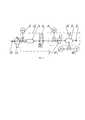
На фиг. 1 изображена схема пневматического испытательного стенда для проверки работоспособности газовых редукторов летательных аппаратов.In FIG. 1 shows a diagram of a pneumatic test bench for verifying the operability of gas reducers of aircraft.
На фиг. 1 позициями обозначены:In FIG. 1 positions marked:
1 - кран впускной;1 - intake valve;
2 - манометр высокого давления;2 - pressure gauge;
3 - емкость, имитирующая штатный накопитель давления;3 - capacity simulating a standard pressure accumulator;
4 - электропневмоклапан;4 - electro-pneumatic valve;
5 - фильтр тонкой очистки;5 - fine filter;
6 - манометр входного давления;6 - input pressure gauge;
7 - объект испытаний;7 - test object;
8 - компенсирующая емкость;8 - compensating capacity;
9 - дроссельная шайба постоянного сечения;9 - throttle washer of constant cross section;
10 - манометр самопишущий;10 - self-recording manometer;
11 - предохранительный клапан;11 - safety valve;
12 - манометр выходного давления;12 - outlet pressure gauge;
13 - термобарокамера.13 - thermal pressure chamber.
Способ проверки работоспособности газовых редукторов летательных аппаратов состоит в следующем:The method of checking the performance of gas reducers of aircraft consists in the following:
Располагают в термобарокамере 13 емкость, имитирующую штатный накопитель давления 3 летательного аппарата (далее емкость 3), электропневмоклапан 4, объект испытаний 7 - газовый редуктор, компенсирующую емкость 8 и дроссельную шайбу 9, в указанной последовательности соединенные с помощью трубопроводов, и предохранительный клапан 11, с помощью трубопровода соединенный с компенсирующей емкостью 8, при этом устанавливают манометр высокого давления 2 перед входом в емкость 3, манометр входного давления 6 перед входом в объект испытаний 7, а манометр самопишущий 10 и манометр выходного давления 12 соединяют с компенсирующей емкостью 8.In a pressure chamber 13 a container is simulated that simulates a
Перед началом работы, в нормальных условиях, открывают впускной кран 1 и в емкость 3 через фильтр тонкой очистки 5 подают рабочее тело, например, воздух, до необходимой величины давления, которую контролируют манометром высокого давления 2. При этом рабочее тело, поступающее в фильтр тонкой очистки 5, уже соответствует техническим требованиям по чистоте от масла, твердых частиц размером более 40 мкм и заданной точке росы. При достижении необходимого давления в емкости 3 закрывают впускной кран 1. Включают термобарокамеру на требуемый режим и производят термостатическую выдержку объекта испытаний 7 в течение заданного времени. С помощью температуры рабочей среды внутри термобарокамеры, определяемой требуемым режимом, имитируют воздействие окружающей среды на летательный аппарат, при этом температура может быть пониженной или повышенной в зависимости от условий, имитируемых при испытаниях. Например, устанавливают пониженную температуру при необходимости имитации условий полета летательного аппарата на определенной высоте (согласно ГОСТ 4401-81 «Атмосфера стандартная. Параметры» температура воздуха на высоте 11000 м, стандартной для полета, например, пассажирских самолетов, составляет -56,5°С), или повышенную - при учете аэродинамического нагрева летательного аппарата. Рабочее тело в емкости 3 и объекте испытаний 7 принимает температуру, установленную внутри термобарокамеры 13. Включают электропневмоклапан 4, и рабочее тело, прошедшее через фильтр тонкой очистки 5, очищенное от твердых частиц размером более 5 мкм, попадает в объект испытаний 7. Давление рабочего тела перед входом в объект испытаний 7 контролируют по манометру входного давления 6. После выхода из объекта испытаний 7 рабочее тело попадает в компенсирующую емкость 8, имитирующую элементы пневмосистемы летательного аппарата, и выходит через дросселирующее устройство, в качестве которого используют дроссельную шайбу постоянного сечения 9. Давление рабочего тела в компенсирующей емкости 8 контролируют по манометру выходного давления 12 и записывают с помощью манометра самопишущего 10. В случае критичного превышения выходного давления рабочего тела над допустимым срабатывает предохранительный клапан 11. После проверки на работоспособность объект испытаний 7 демонтируют из пневматической схемы стенда, а на его место ставят другой и повторяют цикл.Before starting work, under normal conditions, open the
Пневматический испытательный стенд для проверки работоспособности газовых редукторов летательных аппаратов содержит кран впускной 1, манометры 2, 6 и 12, емкость, имитирующую штатный накопитель давления 3 (далее емкость 3), электропневмоклапан 4, фильтр тонкой очистки 5, компенсирующую емкость 8, имитирующую элементы пневмосистемы летательного аппарата, а именно пневматическую схему летательного аппарата, расположенную за редуктором, дросселирующее устройство, выполненное в виде дроссельной шайбы 9 с постоянным сечением, манометр самопишущий 10, предохранительный клапан 11.The pneumatic test bench for checking the operability of gas reducers of aircraft contains an
Кран впускной 1, емкость 3, электропневмоклапан 4, объект испытаний 7 - газовый редуктор, компенсирующая емкость 8 и дроссельная шайба 9 соединены в такой последовательности с помощью трубопроводов, при этом электропневмоклапан 4 соединен с входом объекта испытаний 7, а компенсирующая емкость 8 соединена с выходом объекта испытаний 7. Предохранительный клапан 11 с помощью трубопровода соединен с компенсирующей емкостью 8.
Емкость 3 имитирует накопитель давления летательного аппарата, например, пневмоблок. Компенсирующая емкость 8 имитирует потребители давления, такие, как пневматические средства управления положением аэродинамических поверхностей летательного аппарата.
Манометр высокого давления 2 установлен перед входом в емкость 3. Манометр входного давления 6 установлен перед входом в объект испытаний 7. Манометр самопишущий 10 и манометр выходного давления 12 соединены с компенсирующей емкостью 8.A high pressure gauge 2 is installed in front of the entrance to the
Все элементы данного пневматического стенда, кроме манометров 2, 6 и 12, манометра самопишущего 10 и крана впускного 1, находятся в герметичной емкости, в качестве которой используют термобарокамеру 13.All elements of this pneumatic stand, except for
Пневматический испытательный стенд для проверки работоспособности газовых редукторов летательных аппаратов работает следующим образом:Pneumatic test bench for checking the performance of gas gears of aircraft operates as follows:
Перед началом работы, в нормальных условиях, открывают впускной кран 1 и закачивают рабочее тело в емкость 3 через фильтр тонкой очистки 5 до требуемой величины давления, затем закрывают впускной кран 1 по достижении требуемой величины давления. Включают термобарокамеру 13 на требуемый режим работы, включая требуемую величину температуры и давления внутри термобарокамеры 13, и производят термостатическую выдержку объекта испытаний 7. Включают (открывают) электропневмоклапан 4, за счет чего рабочее тело из емкости 3 попадает в объект испытаний 7, а из объекта испытаний 7 попадает в компенсирующую емкость 8 и далее выходит через дроссельную шайбу 9. Контролируют давление рабочего тела в элементах испытательного стенда с помощью манометров 2, 6 и 12. Записывают давление рабочего тела в компенсирующей емкости 8 с помощью манометра самопишущего 10.Before starting work, under normal conditions, open the
Способ проверки работоспособности газовых редукторов летательных аппаратов и пневматический стенд для его осуществления предназначены для применения в области испытаний элементов летательных аппаратов, а именно методам проверки газовых редукторов летательных аппаратов на пневматических стендах. Способ проверки работоспособности газовых редукторов летательных аппаратов и пневматический стенд для его осуществления позволяют проводить проверку работоспособности газовых редукторов летательного аппарата при требуемых параметрах окружающей среды, включая пониженные и повышенные температуры.A method for verifying the operability of gas reducers of aircraft and a pneumatic stand for its implementation are intended for use in the field of testing elements of aircraft, namely, methods for testing gas reducers of aircraft on pneumatic stands. The method for verifying the operability of gas reducers of aircraft and the pneumatic stand for its implementation make it possible to verify the operability of gas reducers of an aircraft at the required environmental parameters, including low and high temperatures.
Claims (2)
Translated fromRussianPriority Applications (1)
| Application Number | Priority Date | Filing Date | Title |
|---|---|---|---|
| RU2019134063ARU2725114C1 (en) | 2019-10-24 | 2019-10-24 | Method of testing performance of gas reducers of aircrafts and pneumatic test bench for its implementation |
Applications Claiming Priority (1)
| Application Number | Priority Date | Filing Date | Title |
|---|---|---|---|
| RU2019134063ARU2725114C1 (en) | 2019-10-24 | 2019-10-24 | Method of testing performance of gas reducers of aircrafts and pneumatic test bench for its implementation |
Publications (1)
| Publication Number | Publication Date |
|---|---|
| RU2725114C1true RU2725114C1 (en) | 2020-06-29 |
Family
ID=71510163
Family Applications (1)
| Application Number | Title | Priority Date | Filing Date |
|---|---|---|---|
| RU2019134063ARU2725114C1 (en) | 2019-10-24 | 2019-10-24 | Method of testing performance of gas reducers of aircrafts and pneumatic test bench for its implementation |
Country Status (1)
| Country | Link |
|---|---|
| RU (1) | RU2725114C1 (en) |
Cited By (2)
| Publication number | Priority date | Publication date | Assignee | Title |
|---|---|---|---|---|
| CN114459742A (en)* | 2022-01-04 | 2022-05-10 | 西安航天动力试验技术研究所 | Pressure reducer performance test system and multi-mode dynamic performance test method |
| CN119756835A (en)* | 2025-03-05 | 2025-04-04 | 南京自控仪表有限公司 | Pressure reducer reliability testing device |
Citations (5)
| Publication number | Priority date | Publication date | Assignee | Title |
|---|---|---|---|---|
| SU405448A1 (en)* | 1972-02-09 | 1980-04-25 | Mikhajlov V A | Stand for testing gas pressure control systems |
| CN101598635A (en)* | 2009-05-31 | 2009-12-09 | 广州飞机维修工程有限公司 | A kind of test device of oxygen regulator for aircraft passengers |
| RU2467302C1 (en)* | 2011-05-19 | 2012-11-20 | Федеральное государственное унитарное предприятие "Центральный институт авиационного моторостроения имени П.И. Баранова" | Altitude test bench for double-flow jet turbine engines, and its operating method (versions) |
| US20140053641A1 (en)* | 2011-03-29 | 2014-02-27 | Florida Turbine Technologies, Inc. | Apparatus and process for testing an industrial gas turbine engine and components thereof |
| RU167179U1 (en)* | 2016-04-14 | 2016-12-27 | Публичное акционерное общество "КАМАЗ" | STAND OF NON-MOTOR TESTS OF COMPONENTS OF GAS ENGINES |
- 2019
- 2019-10-24RURU2019134063Apatent/RU2725114C1/enactive
Patent Citations (6)
| Publication number | Priority date | Publication date | Assignee | Title |
|---|---|---|---|---|
| SU405448A1 (en)* | 1972-02-09 | 1980-04-25 | Mikhajlov V A | Stand for testing gas pressure control systems |
| CN101598635A (en)* | 2009-05-31 | 2009-12-09 | 广州飞机维修工程有限公司 | A kind of test device of oxygen regulator for aircraft passengers |
| CN101598635B (en)* | 2009-05-31 | 2011-07-20 | 广州飞机维修工程有限公司 | Test device of oxygen regulator for aircraft passengers |
| US20140053641A1 (en)* | 2011-03-29 | 2014-02-27 | Florida Turbine Technologies, Inc. | Apparatus and process for testing an industrial gas turbine engine and components thereof |
| RU2467302C1 (en)* | 2011-05-19 | 2012-11-20 | Федеральное государственное унитарное предприятие "Центральный институт авиационного моторостроения имени П.И. Баранова" | Altitude test bench for double-flow jet turbine engines, and its operating method (versions) |
| RU167179U1 (en)* | 2016-04-14 | 2016-12-27 | Публичное акционерное общество "КАМАЗ" | STAND OF NON-MOTOR TESTS OF COMPONENTS OF GAS ENGINES |
Cited By (3)
| Publication number | Priority date | Publication date | Assignee | Title |
|---|---|---|---|---|
| CN114459742A (en)* | 2022-01-04 | 2022-05-10 | 西安航天动力试验技术研究所 | Pressure reducer performance test system and multi-mode dynamic performance test method |
| CN114459742B (en)* | 2022-01-04 | 2024-05-03 | 西安航天动力试验技术研究所 | Pressure reducer performance test system and multi-mode dynamic performance test method |
| CN119756835A (en)* | 2025-03-05 | 2025-04-04 | 南京自控仪表有限公司 | Pressure reducer reliability testing device |
Similar Documents
| Publication | Publication Date | Title |
|---|---|---|
| CN104990669B (en) | Surge pressure sensor field calibration device | |
| RU2725114C1 (en) | Method of testing performance of gas reducers of aircrafts and pneumatic test bench for its implementation | |
| CN208653782U (en) | Liquid flow test device for liquid rocket engine thrust chamber | |
| CN110926731B (en) | A high-pressure gas leakage and diffusion linkage measurement test system | |
| CN106200668A (en) | Outer loop energy resource system and test method thereof for semi-physical simulation | |
| CN110455519A (en) | A lateral stiffness test system for high-temperature internal pressure shear deformation of piping systems | |
| CN104089765B (en) | Valve hot test device | |
| CN202003552U (en) | Pipeline water hammer demonstrating and measuring device | |
| US8413530B2 (en) | Use of buoyant gases for the simulation of real fire sources | |
| CN205327441U (en) | Aircraft fuel oil system's testing arrangement under simulated high -altitude environment | |
| CN105352735A (en) | Engine plateau air inlet simulation device | |
| CN103792082A (en) | Safety return valve detecting device and method | |
| CN203688224U (en) | Engine driven air pressure system high altitude simulation tester | |
| CN118794698A (en) | A lubricating oil tank test system and method under simulated overload conditions | |
| CN108801579A (en) | Dynamic pressure quick response balance system and its application | |
| RU2693053C1 (en) | Apparatus for testing hydraulic fluids | |
| CN112557045A (en) | Diesel engine box body simulation test bench system for simulating plateau altitude climate and test method thereof | |
| CN203444329U (en) | Air leakage testing stand | |
| CN110895202A (en) | A test device to study the influence of environmental factors on flow measurement | |
| CN114486274B (en) | Device and method for verifying decompression system of nacelle of aircraft engine | |
| Moruzzi et al. | Liquid rocket engine component water-flow test stand | |
| CN204788788U (en) | On --spot calibrating device of surge pressure sensor | |
| Scroggins | A streamlined approach to venturi sizing | |
| RU2232701C2 (en) | Method of monitoring quality of manufacture of direct-acting thermo-regulator and device for realization of this method | |
| CN106441910B (en) | Solid engines High Voltage cold air quick washing load test system and method |