RU2724011C1 - Automated device for injections - Google Patents
Automated device for injectionsDownload PDFInfo
- Publication number
- RU2724011C1 RU2724011C1RU2019115809ARU2019115809ARU2724011C1RU 2724011 C1RU2724011 C1RU 2724011C1RU 2019115809 ARU2019115809 ARU 2019115809ARU 2019115809 ARU2019115809 ARU 2019115809ARU 2724011 C1RU2724011 C1RU 2724011C1
- Authority
- RU
- Russia
- Prior art keywords
- main body
- cartridge
- cartridge holder
- drug
- dose
- Prior art date
Links
- 238000002347injectionMethods0.000titleclaimsabstractdescription29
- 239000007924injectionSubstances0.000titleclaimsabstractdescription29
- 239000003814drugSubstances0.000claimsabstractdescription40
- 229940079593drugDrugs0.000claimsabstractdescription35
- 239000007788liquidSubstances0.000claimsabstractdescription12
- 238000007689inspectionMethods0.000claimsabstractdescription5
- 230000000007visual effectEffects0.000claimsdescription30
- 239000000463materialSubstances0.000claimsdescription8
- 239000003086colorantSubstances0.000claimsdescription2
- 239000000126substanceSubstances0.000abstract1
- NOESYZHRGYRDHS-UHFFFAOYSA-NinsulinChemical compoundN1C(=O)C(NC(=O)C(CCC(N)=O)NC(=O)C(CCC(O)=O)NC(=O)C(C(C)C)NC(=O)C(NC(=O)CN)C(C)CC)CSSCC(C(NC(CO)C(=O)NC(CC(C)C)C(=O)NC(CC=2C=CC(O)=CC=2)C(=O)NC(CCC(N)=O)C(=O)NC(CC(C)C)C(=O)NC(CCC(O)=O)C(=O)NC(CC(N)=O)C(=O)NC(CC=2C=CC(O)=CC=2)C(=O)NC(CSSCC(NC(=O)C(C(C)C)NC(=O)C(CC(C)C)NC(=O)C(CC=2C=CC(O)=CC=2)NC(=O)C(CC(C)C)NC(=O)C(C)NC(=O)C(CCC(O)=O)NC(=O)C(C(C)C)NC(=O)C(CC(C)C)NC(=O)C(CC=2NC=NC=2)NC(=O)C(CO)NC(=O)CNC2=O)C(=O)NCC(=O)NC(CCC(O)=O)C(=O)NC(CCCNC(N)=N)C(=O)NCC(=O)NC(CC=3C=CC=CC=3)C(=O)NC(CC=3C=CC=CC=3)C(=O)NC(CC=3C=CC(O)=CC=3)C(=O)NC(C(C)O)C(=O)N3C(CCC3)C(=O)NC(CCCCN)C(=O)NC(C)C(O)=O)C(=O)NC(CC(N)=O)C(O)=O)=O)NC(=O)C(C(C)CC)NC(=O)C(CO)NC(=O)C(C(C)O)NC(=O)C1CSSCC2NC(=O)C(CC(C)C)NC(=O)C(NC(=O)C(CCC(N)=O)NC(=O)C(CC(N)=O)NC(=O)C(NC(=O)C(N)CC=1C=CC=CC=1)C(C)C)CC1=CN=CN1NOESYZHRGYRDHS-UHFFFAOYSA-N0.000description6
- 101000579646Penaeus vannamei Penaeidin-1Proteins0.000description4
- 102000004877InsulinHuman genes0.000description3
- 108090001061InsulinProteins0.000description3
- 229940125396insulinDrugs0.000description3
- 238000012986modificationMethods0.000description2
- 230000004048modificationEffects0.000description2
- -1for exampleSubstances0.000description1
- 238000000034methodMethods0.000description1
- 230000000149penetrating effectEffects0.000description1
- 230000002265preventionEffects0.000description1
- 238000005096rolling processMethods0.000description1
- 239000012780transparent materialSubstances0.000description1
Images


Classifications
- A—HUMAN NECESSITIES
- A61—MEDICAL OR VETERINARY SCIENCE; HYGIENE
- A61M—DEVICES FOR INTRODUCING MEDIA INTO, OR ONTO, THE BODY; DEVICES FOR TRANSDUCING BODY MEDIA OR FOR TAKING MEDIA FROM THE BODY; DEVICES FOR PRODUCING OR ENDING SLEEP OR STUPOR
- A61M5/00—Devices for bringing media into the body in a subcutaneous, intra-vascular or intramuscular way; Accessories therefor, e.g. filling or cleaning devices, arm-rests
- A61M5/178—Syringes
- A61M5/24—Ampoule syringes, i.e. syringes with needle for use in combination with replaceable ampoules or carpules, e.g. automatic
- A—HUMAN NECESSITIES
- A61—MEDICAL OR VETERINARY SCIENCE; HYGIENE
- A61M—DEVICES FOR INTRODUCING MEDIA INTO, OR ONTO, THE BODY; DEVICES FOR TRANSDUCING BODY MEDIA OR FOR TAKING MEDIA FROM THE BODY; DEVICES FOR PRODUCING OR ENDING SLEEP OR STUPOR
- A61M5/00—Devices for bringing media into the body in a subcutaneous, intra-vascular or intramuscular way; Accessories therefor, e.g. filling or cleaning devices, arm-rests
- A61M5/178—Syringes
- A61M5/20—Automatic syringes, e.g. with automatically actuated piston rod, with automatic needle injection, filling automatically
- A—HUMAN NECESSITIES
- A61—MEDICAL OR VETERINARY SCIENCE; HYGIENE
- A61M—DEVICES FOR INTRODUCING MEDIA INTO, OR ONTO, THE BODY; DEVICES FOR TRANSDUCING BODY MEDIA OR FOR TAKING MEDIA FROM THE BODY; DEVICES FOR PRODUCING OR ENDING SLEEP OR STUPOR
- A61M5/00—Devices for bringing media into the body in a subcutaneous, intra-vascular or intramuscular way; Accessories therefor, e.g. filling or cleaning devices, arm-rests
- A61M5/178—Syringes
- A61M5/31—Details
- A61M5/315—Pistons; Piston-rods; Guiding, blocking or restricting the movement of the rod or piston; Appliances on the rod for facilitating dosing ; Dosing mechanisms
- A61M5/31533—Dosing mechanisms, i.e. setting a dose
- A61M5/31545—Setting modes for dosing
- A61M5/31548—Mechanically operated dose setting member
- A61M5/3155—Mechanically operated dose setting member by rotational movement of dose setting member, e.g. during setting or filling of a syringe
- A—HUMAN NECESSITIES
- A61—MEDICAL OR VETERINARY SCIENCE; HYGIENE
- A61M—DEVICES FOR INTRODUCING MEDIA INTO, OR ONTO, THE BODY; DEVICES FOR TRANSDUCING BODY MEDIA OR FOR TAKING MEDIA FROM THE BODY; DEVICES FOR PRODUCING OR ENDING SLEEP OR STUPOR
- A61M5/00—Devices for bringing media into the body in a subcutaneous, intra-vascular or intramuscular way; Accessories therefor, e.g. filling or cleaning devices, arm-rests
- A61M5/178—Syringes
- A61M5/20—Automatic syringes, e.g. with automatically actuated piston rod, with automatic needle injection, filling automatically
- A61M2005/2006—Having specific accessories
- A—HUMAN NECESSITIES
- A61—MEDICAL OR VETERINARY SCIENCE; HYGIENE
- A61M—DEVICES FOR INTRODUCING MEDIA INTO, OR ONTO, THE BODY; DEVICES FOR TRANSDUCING BODY MEDIA OR FOR TAKING MEDIA FROM THE BODY; DEVICES FOR PRODUCING OR ENDING SLEEP OR STUPOR
- A61M5/00—Devices for bringing media into the body in a subcutaneous, intra-vascular or intramuscular way; Accessories therefor, e.g. filling or cleaning devices, arm-rests
- A61M5/178—Syringes
- A61M5/24—Ampoule syringes, i.e. syringes with needle for use in combination with replaceable ampoules or carpules, e.g. automatic
- A61M2005/2403—Ampoule inserted into the ampoule holder
- A—HUMAN NECESSITIES
- A61—MEDICAL OR VETERINARY SCIENCE; HYGIENE
- A61M—DEVICES FOR INTRODUCING MEDIA INTO, OR ONTO, THE BODY; DEVICES FOR TRANSDUCING BODY MEDIA OR FOR TAKING MEDIA FROM THE BODY; DEVICES FOR PRODUCING OR ENDING SLEEP OR STUPOR
- A61M5/00—Devices for bringing media into the body in a subcutaneous, intra-vascular or intramuscular way; Accessories therefor, e.g. filling or cleaning devices, arm-rests
- A61M5/178—Syringes
- A61M5/24—Ampoule syringes, i.e. syringes with needle for use in combination with replaceable ampoules or carpules, e.g. automatic
- A61M2005/2485—Ampoule holder connected to rest of syringe
- A61M2005/2488—Ampoule holder connected to rest of syringe via rotation, e.g. threads or bayonet
- A—HUMAN NECESSITIES
- A61—MEDICAL OR VETERINARY SCIENCE; HYGIENE
- A61M—DEVICES FOR INTRODUCING MEDIA INTO, OR ONTO, THE BODY; DEVICES FOR TRANSDUCING BODY MEDIA OR FOR TAKING MEDIA FROM THE BODY; DEVICES FOR PRODUCING OR ENDING SLEEP OR STUPOR
- A61M5/00—Devices for bringing media into the body in a subcutaneous, intra-vascular or intramuscular way; Accessories therefor, e.g. filling or cleaning devices, arm-rests
- A61M5/178—Syringes
- A61M5/31—Details
- A61M2005/3125—Details specific display means, e.g. to indicate dose setting
- A61M2005/3126—Specific display means related to dosing
- A—HUMAN NECESSITIES
- A61—MEDICAL OR VETERINARY SCIENCE; HYGIENE
- A61M—DEVICES FOR INTRODUCING MEDIA INTO, OR ONTO, THE BODY; DEVICES FOR TRANSDUCING BODY MEDIA OR FOR TAKING MEDIA FROM THE BODY; DEVICES FOR PRODUCING OR ENDING SLEEP OR STUPOR
- A61M2205/00—General characteristics of the apparatus
- A61M2205/58—Means for facilitating use, e.g. by people with impaired vision
- A61M2205/583—Means for facilitating use, e.g. by people with impaired vision by visual feedback
- A61M2205/585—Means for facilitating use, e.g. by people with impaired vision by visual feedback having magnification means, e.g. magnifying glasses
Landscapes
- Health & Medical Sciences (AREA)
- Vascular Medicine (AREA)
- Engineering & Computer Science (AREA)
- Anesthesiology (AREA)
- Biomedical Technology (AREA)
- Heart & Thoracic Surgery (AREA)
- Hematology (AREA)
- Life Sciences & Earth Sciences (AREA)
- Animal Behavior & Ethology (AREA)
- General Health & Medical Sciences (AREA)
- Public Health (AREA)
- Veterinary Medicine (AREA)
- Infusion, Injection, And Reservoir Apparatuses (AREA)
- Ink Jet (AREA)
Abstract
Description
Translated fromRussianОбласть техники, к которой относится изобретениеFIELD OF THE INVENTION
Настоящее изобретение относится в целом к автоматизированным устройствам для инъекций. Более конкретно, настоящее изобретение относится к шприц-ручке для инъекций лекарственных средств, снабженной визуальным индикатором дозы и, в частности, индикатором правильности соединения ее основных компонентов.The present invention relates generally to automated injection devices. More specifically, the present invention relates to a syringe pen for injection of drugs, equipped with a visual dose indicator and, in particular, an indicator of the correct connection of its main components.
Для настоящей заявки испрашивается конвенционный приоритет по заявке US 61/624,218, поданной 13 апреля 2012 г., полное содержание которой вводится здесь ссылкой.For this application claims the convention priority for the application US 61 / 624,218, filed April 13, 2012, the full contents of which are introduced here by reference.
Уровень техникиState of the art
Инсулин и другие впрыскиваемые лекарственные средства обычно вводят с помощью шприц-ручек, которые прикрепляют к контейнерам (картриджам) для подачи лекарственного средства из контейнера через иглу шприц-ручки в организм пациента.Insulin and other injectable drugs are usually administered using syringe pens that are attached to containers (cartridges) to deliver the drug from the container through the needle of the syringe pen to the patient.
Конструкция и действие типичной шприц-ручки для введения лекарственных средств описаны в публикации заявки US 2006/0229562 (заявители Marsh и др.) от 12.10.2006, полное содержание которой вводится здесь ссылкой. Такие шприц-ручки обычно имеют регулятор, с помощью которого можно задавать точное количество лекарственного средства, которое должно быть введено. Однако точность дозирования основывается на предположении надлежащего соединения основных компонентов шприц-ручки, а именно основного корпуса с задающим регулятором и держателя картриджа с жидким лекарственным средством. Из основного корпуса выдвигается приводной механизм, такой как поршень, которые давит на картридж с лекарственным средством, помещенный в держатель, и его перемещение зависит от правильности прикрепления основного корпуса к держателю картриджа. Однако надлежащее соединение между основным корпусом и держателем картриджа может быть нарушено из-за ошибки пользователя, или из-за вибрации, или из-за непредусмотренного механического воздействия, в результате чего может произойти частичное рассоединение основного корпуса и держателя картриджа.The design and operation of a typical syringe pen for administering drugs are described in the publication of application US 2006/0229562 (applicants Marsh et al.) Dated 12/10/2006, the full contents of which are incorporated herein by reference. Such syringe pens usually have a regulator with which you can specify the exact amount of drug that must be administered. However, the dosing accuracy is based on the assumption that the main components of the syringe pen are properly connected, namely the main body with the master regulator and the cartridge holder with the liquid drug. A drive mechanism, such as a piston, extends from the main body, which presses on the drug cartridge placed in the holder, and its movement depends on the correct attachment of the main body to the cartridge holder. However, the proper connection between the main body and the cartridge holder may be broken due to a user error, or due to vibration, or due to unintended mechanical stress, which may result in partial disconnection of the main body and the cartridge holder.
Соответственно, существует потребность в улучшенной шприц-ручке, в которой обеспечивается индикация для пользователя дозы и ненадлежащего соединении основных компонентов шприц-ручки, для избежания потенциальных возможностей введения в организм пациента неправильной дозы лекарственного средства.Accordingly, there is a need for an improved syringe pen, which provides an indication to the user of the dose and improper connection of the main components of the syringe pen, in order to avoid the potential for introducing the wrong dose of the drug into the patient.
Раскрытие изобретенияDisclosure of invention
В настоящем изобретении предлагается автоматизированное устройство для инъекций (шприц-ручка) с визуальным индикатором дозы для наблюдения пользователем и предупреждения введения в организм пользователя неверной дозы лекарственного средства.The present invention provides an automated injection device (pen-syringe) with a visual dose indicator for user observation and prevention of the introduction of an incorrect dose of a drug into the user's body.
А именно, предлагается автоматизированное устройство для инъекций, содержащее:Namely, an automated injection device is proposed comprising:
основной корпус с проемом, содержащий задающий регулятор дозы;the main body with an opening containing a master dose adjuster;
держатель картриджа для удерживания картриджа с жидким лекарственным средством, прикрепляемый к основному корпусу, причем по меньшей мере один из держателя картриджа и картриджа с лекарственным средством содержит приемную часть для иглы;a cartridge holder for holding a liquid drug cartridge attached to the main body, at least one of the cartridge holder and drug cartridge containing a receptacle for a needle;
приводной механизм для воздействия с усилием на картридж с лекарственным средством и вытеснения жидкого лекарственного средства из картриджа; иa drive mechanism for exposing the cartridge to the drug with force and displacing the liquid drug from the cartridge; and
индикатор дозы, имеющий указатель для индикации дозы, которая должна быть введена, и формируемый концевой накладкой со смотровым окошком, закрывающей часть корпуса, при этом смотровое окошко обеспечивает возможность обзора сквозь него части корпуса вокруг проема корпуса.a dose indicator having a pointer to indicate the dose to be administered, and formed by an end plate with a viewing window covering part of the housing, while the viewing window allows for viewing through it of the housing around the opening of the housing.
В вариантах выполнения накладка включает первый визуально наблюдаемый (далее - визуальный) материал, а основной корпус включает второй визуальный материал, причем первый и второй визуальные материалы имеют разные цвета.In embodiments, the overlay includes a first visually observable (hereinafter, visual) material, and the main body includes a second visual material, the first and second visual materials having different colors.
Указатель расположен в центральной части смотрового окошка и проема корпуса.The pointer is located in the central part of the inspection window and the opening of the housing.
Смотровое окошко имеет по существу круговую или эллиптическую форму.The viewing window has a substantially circular or elliptical shape.
Автоматизированное устройство дополнительно содержит колпачок, закрывающий часть держателя картриджа с возможностью снятия.The automated device further comprises a cap that can be removed to cover a portion of the cartridge holder.
Шприц-ручка может дополнительно иметь визуальный индикатор для индикации надлежащего соединения основного корпуса и держателя картриджа и предупреждения пользователя о ненадлежащем соединении основных компонентов шприц-ручки, что также может приводить к введению в организм пользователя неверной дозы лекарственного средства. В различных вариантах выполнения такой визуальный индикатор включает первую визуальную отметку на держателе картриджа и вторую визуальную отметку на основном корпусе, так что когда держатель картриджа и основной корпус соединены надлежащим образом, визуальные отметки совмещены. Визуальные отметки могут представлять собой возвышения на держателе картриджа и на основном корпусе. Визуальные отметки могут быть идентичны или различны. Отметка на основном корпусе может представлять собой возвышение и содержать удлиненный выступ.The syringe pen may additionally have a visual indicator to indicate the proper connection of the main body and the cartridge holder and warn the user about the improper connection of the main components of the syringe pen, which can also lead to the introduction of the wrong dose of the drug into the user's body. In various embodiments, such a visual indicator includes a first visual mark on the cartridge holder and a second visual mark on the main body, so that when the cartridge holder and the main body are connected properly, the visual marks are aligned. Visual marks may represent elevations on the cartridge holder and on the main body. Visual marks can be identical or different. The mark on the main body may be an elevation and comprise an elongated protrusion.
Основной корпус может иметь окошко задающего регулятора для визуальной индикации пользователю величины дозы, которую задают с помощью задающего регулятора. Дополнительно может иметься отметка индикатора на основном корпусе, совмещаемая с задаваемой дозой лекарственного средства, для помощи пользователю в задании необходимой дозы лекарственного средства. Основной корпус может дополнительно содержать накладку, охватывающую периферию окошка задающего регулятора и указатель, отходящий от накладки в направлении окошка задающего регулятора для помощи пользователю в задании необходимой дозы лекарственного средства.The main body may have a window adjusting the regulator for visual indication to the user of the dose that is set using the adjusting regulator. Additionally, there may be an indicator mark on the main body, combined with a preset dose of the drug, to assist the user in setting the required dose of the drug. The main body may further comprise an overlay covering the periphery of the window of the master regulator and a pointer extending from the overlay in the direction of the window of the master regulator to assist the user in setting the required dose of the drug.
Задающий регулятор может быть выполнен в виде головки.The master controller may be made in the form of a head.
Приводной механизм может содержать винт подачи, расположенный внутри картриджа с возможностью перемещения и присоединенный к задающему регулятору с возможностью перемещения.The drive mechanism may include a feed screw located within the cartridge with the possibility of movement and attached to the master controller with the possibility of movement.
В одном из вариантов лекарственное средство содержит инсулин.In one embodiment, the drug comprises insulin.
Визуальный индикатор надлежащего соединения может включать первую визуальную отметку на держателе картриджа и вторую визуальную отметку на основном корпусе, так что когда держатель картриджа и основной корпус соединены надлежащим образом, визуальные отметки совмещены.The proper connection visual indicator may include a first visual mark on the cartridge holder and a second visual mark on the main body, so that when the cartridge holder and the main body are connected properly, the visual marks are aligned.
Колпачок может быть выполнен из прозрачного или полупрозрачного материала, так что видна отметка на держателе картриджа, когда к нему прикреплен колпачок.The cap may be made of a transparent or translucent material, so that the mark on the cartridge holder is visible when the cap is attached to it.
Целью настоящего изобретения является создание различных вариантов визуальных индикаторов, которые могут использоваться для вышеуказанных целей.The aim of the present invention is to provide various options for visual indicators that can be used for the above purposes.
Эти и другие цели в целом достигаются в предложенном автоматизированном устройстве для инъекций в форме шприц-ручки, имеющей основной корпус с задающим регулятором дозы и держатель картриджа.These and other goals are generally achieved in the proposed automated device for injection in the form of a syringe pen having a main body with a master dose regulator and a cartridge holder.
Краткое описание чертежейBrief Description of the Drawings
Различные цели, достоинства и новые признаки иллюстративных вариантов осуществления изобретения можно будет лучше понять из нижеприведенного подробного описания со ссылками на прилагаемые чертежи, на которых показано:Various objectives, advantages and new features of illustrative embodiments of the invention can be better understood from the following detailed description with reference to the accompanying drawings, which show:
на фиг. 1 вид в перспективе шприц-ручки в соответствии с одним из вариантов осуществления настоящего изобретения;in FIG. 1 is a perspective view of a syringe pen in accordance with one embodiment of the present invention;
на фиг. 2 вид в перспективе шприц-ручки фиг. 1 со снятым колпачком;in FIG. 2 is a perspective view of the syringe pen of FIG. 1 with cap removed;
на фиг. 3 - увеличенный вид визуального индикатора, показывающего надлежащее прикрепление держателя картриджа с лекарственным средством к основному корпусу шприц-ручки фиг. 1;in FIG. 3 is an enlarged view of a visual indicator showing proper attachment of the drug cartridge holder to the main body of the syringe pen of FIG. 1;
на фиг. 4 увеличенный вид окошка индикатора дозы лекарственного средства, которая должна быть введена шприц-ручкой фиг. 1;in FIG. 4 is an enlarged view of the drug dose indicator window to be inserted by the syringe pen of FIG. 1;
на фиг. 5 вид в перспективе шприц-ручки в соответствии с другим вариантом осуществления настоящего изобретения;in FIG. 5 is a perspective view of a pen in accordance with another embodiment of the present invention;
на фиг. 6 вид в перспективе шприц-ручки фиг. 5 со снятым колпачком;in FIG. 6 is a perspective view of the syringe pen of FIG. 5 with the cap removed;
на фиг. 7 - увеличенный вид визуального индикатора, показывающего надлежащее прикрепление держателя картриджа с лекарственным средством к основному корпусу шприц-ручки фиг. 5;in FIG. 7 is an enlarged view of a visual indicator showing proper attachment of the drug cartridge holder to the main body of the syringe pen of FIG. five;
на фиг. 8 увеличенный вид окошка индикатора дозы лекарственного средства, которая должна быть введена шприц-ручкой фиг. 5;in FIG. 8 is an enlarged view of the drug dose indicator window to be inserted by the syringe pen of FIG. five;
на фиг. 9 - вид в перспективе шприц-ручки в соответствии еще с одним вариантом осуществления настоящего изобретения;in FIG. 9 is a perspective view of a syringe pen in accordance with yet another embodiment of the present invention;
на фиг. 10 вид в перспективе шприц-ручки фиг. 9 со снятым колпачком;in FIG. 10 is a perspective view of the syringe pen of FIG. 9 with the cap removed;
на фиг. 11 увеличенный вид визуального индикатора, показывающего надлежащее прикрепление держателя картриджа с лекарственным средством к основному корпусу шприц-ручки фиг. 9;in FIG. 11 is an enlarged view of a visual indicator showing proper attachment of the drug cartridge holder to the main body of the syringe pen of FIG. nine;
на фиг. 12 - увеличенный вид окошка индикатора дозы лекарственного средства, которая должна быть введена шприц-ручкой фиг. 9.in FIG. 12 is an enlarged view of a window of a drug dose indicator to be inserted by the syringe pen of FIG. nine.
Осуществление изобретенияThe implementation of the invention
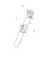
На фиг. 1-4 представлен один из вариантов автоматизированного устройства для инъекций по настоящему изобретению. Автоматизированное устройство 1 для инъекций включает основной корпус 2, держатель 3 картриджа и колпачок 4. В держателе 3 картриджа устанавливают разовый картридж (не показан), содержащий жидкое лекарственное средство, такое как, например, инсулин. Держатель 3 картриджа крепится к основному корпусу 2, предпочтительно с помощью внешней резьбы на основном корпусе 2 и внутренней резьбы на держателе 3 картриджа. Основной корпус 2 содержит задающий регулятор 29 (дозы), предпочтительно в форме поворотной головки. Пользователь вращает головку задающего регулятора 29 для задания соответствующей дозы лекарственного средства, которая должна быть введена, путем установки необходимой величины в окошке/проеме 24 и затем нажимает на головку задающего регулятора 29, в результате чего приводной механизм, такой как поршень (не показан), будет воздействовать на картридж, соединенный с иглой, для подачи необходимого количества жидкого лекарственного средства под кожу пользователя.In FIG. 1-4 show one embodiment of an automated injection device of the present invention. The
Задающий регулятор 29 откалиброван в предположении, что держатель 3 картриджа надлежащим образом прикреплен к основному корпусу 2. Однако, если держатель 3 картриджа и основной корпус 2 соединены ненадлежащим образом, пользователь может не получить точную дозу лекарственного средства. Например, если держатель 3 картриджа находится на большем расстоянии от основного корпуса 2, чем оно должно быть в расчетном положении их соединения, поршень (не показан), приводимый в действие задающим регулятором 29, может перемещаться на заданную длину, которая может быть недостаточна для доставки необходимой дозы из-за неправильного прикрепления держателя 3 картриджа к основному корпусу 2.The
На фиг. 1 показана шприц-ручка 1 для инъекций с колпачком 4, прикрепленным к держателю 3 картриджа, который надлежащим образом соединен с основным корпусом 2. Индикация надлежащего соединения между основным корпусом 2 и держателем 3 картриджа происходит, когда метка 21 индикатора на основном корпусе 2 и метка 31 индикатора на держателе 3 картриджа вращательно (при их вращении относительно друг друга) совмещаются в продольном направлении или вдоль оси автоматизированного устройства 1 для инъекций. На фиг. 1, видна только часть держателя 3 картриджа, а остальная ее часть закрыта колпачком 4, надетым на держатель 3.In FIG. 1 shows an
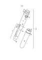
На фиг. 2 показана шприц-ручка 1 фиг. 1 с колпачком 4, снятым с держателя 3 картриджа. Держатель 3 картриджа имеет окошко 33, через которое можно видеть картридж с жидким лекарственным средством (когда он установлен). Держатель 3 картриджа имеет на открытом конце приемную часть 35 для инъекционной иглы, к которой может быть прикреплена втулка с проникающей канюлей иглы для прокалывания картриджа и иглой для прокалывания кожи пользователя перед инъекцией. На держателе 3 картриджа имеется внешний кольцевой выступ 36, и на колпачке 4 имеется внутренний кольцевой выступ 46. При надвигании колпачка 4 на держатель 3 картриджа соответствующие кольцевые выступы 36, 46 входят в зацепление, предотвращая дальнейшее перемещение колпачка 4 относительно держателя 3 картриджа. Колпачок 4 может быть снабжен внешним кольцевым выступом 42, который помогает пользователю удерживать колпачок в процессе его надевания на держатель 3 картриджа и снятия с него.In FIG. 2 shows the
Шприц-ручка 1 для инъекций включает визуальные индикаторы 21, 22 и
31, 32 для индикации надлежащего соединения держателя 3 картриджа и основного корпуса 2. Как показано на фиг. 2 и 3, держатель 3 картриджа снабжен визуальным индикатором в форме указателя 31 и продольного выступа31, 32 to indicate proper connection of the
32, на котором расположен указатель 31. Продольный выступ 32 также предотвращает перекатывание шприц-ручки 1 для инъекций, когда она лежит на плоской поверхности (например, на столе). Основной корпус 2 снабжен визуальным индикатором в форме указателя 21, расположенного на выступающей части 22. Если держатель 3 картриджа и основной корпус 2 соединены надлежащим образом, предпочтительно путем свинчивания вместе этих частей, указатели 21 и 31, а также выступающая часть 22 и удлиненный выступ 32 будут находиться на одной линии в продольном направлении автоматизированного устройства для инъекций, как это показано на фиг. 1-3. Если держатель 3 картриджа и основной корпус 2 прикреплены друг к другу ненадлежащим образом, визуальные индикаторы 21, 22 и 31, 32 не будут находиться на одной линии, как это показано на фиг. 2 (то есть они могут быть смещены относительно друг друга в продольном направлении и/или по углу). Продольный выступ 32 и выступающая часть 22 могут помогать плохо видящим пользователям в определении состояния соединения держателя 3 картриджа и основного корпуса 2.32, on which the
Линия 7 на фиг. 1-3 показывает границу соединения между держателем 3 картриджа и основным корпусом 2. Линия 8 на фиг. 1 и 3, показывает границу соединения между колпачком 4 и держателем 3 картриджа.
На фиг. 3 приведен увеличенный вид автоматизированного устройства 1 для инъекций, на котором колпачок 4 прикреплен к держателю 3 картриджа, который надлежащим образом прикреплен к основному корпусу 2. Как показано, визуальные индикаторы надлежащего положения в форме указателей 21, 31, а также выступающих частей 22, 32, указывают пользователю, что держатель 3 картриджа надлежащим образом прикреплен к основному корпусу 2, и пользователь может определить это визуально или на ощупь.In FIG. 3 is an enlarged view of an
На фиг. 4 приведен увеличенный вид окошка 24 основного корпуса 2 автоматизированного устройства 1 для инъекций, показанного на фиг. 1. В окошке 24 индицируется величина дозы жидкого лекарственного средства, задаваемой пользователем с помощью головки задающего регулятора 29. Окошко 24 визуально выделяется накладкой 26 его, охватывающей его со всех сторон. Накладка 26 имеет указатель 27, указывающий на численную величину количества жидкого лекарственного средства, соответствующего дозе, задаваемой головкой задающего регулятора 29. Регулятор 29 предпочтительно представляет собой поворотную шкалу или головку, на которой имеются лунки или небольшие выступы, обеспечивающие пользователю надежный захват устройства.In FIG. 4 is an enlarged view of the
Накладка 26 окошка 24, показанная на фиг. 4, может быть элементом, отдельным от основного корпуса 2, или же может быть наплавлена на него. В другом варианте накладка 26 окошка 24 может быть нанесена на основной корпус 2 способом печати. В любом случае предпочтительно, чтобы накладка 26 окошка 24 имела такой же цвет, что и задающий регулятор 29. Кроме того, предпочтительно, чтобы проем/окошко 260 в накладке 26 имел такие размеры, чтобы он был больше, чем проем 200 в основном корпусе, для показа части 201. В предпочтительных вариантах проем 200 в основном корпусе имеет такую форму, чтобы он соответствовал винтовой линии, по которой нанесены численные величины, соответствующие дозам, задаваемым с помощью задающего регулятора 29. Более предпочтительно, чтобы проем 200 в основном корпусе представлял собой удлиненный вырез, ориентированный в направлении винтовой линии численных величин, для их показа в проеме 200.The
В одном из вариантов, показанном на фиг. 4, проем 260 накладки представляет собой по существу круговое отверстие с указателем 27, проходящим над частями проема 200 основного корпуса и проема 260. Достоинство такого устройства заключается в том, часть 201 может быть видна для выделения численных величин внутри проема 200 основного корпуса за счет обеспечения контрастного переднего плана.In one embodiment shown in FIG. 4, the
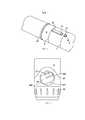
На фиг. 5-8 представлен другой вариант автоматизированного устройства для инъекций по настоящему изобретению. В этом варианте метка индикатора на держателе 3 картриджа представляет собой цилиндр 310 с указателем 31а, проходящим в продольном направлении автоматизированного устройства 1 для инъекций. Если держатель 3 картриджа надлежащим образом прикреплен к основному корпусу 2, указатель 31а держателя 3 картриджа находится напротив указателя 21а основного корпуса 2, как это показано на фиг. 6 и 7. В этом варианте на основном корпусе 2 и колпачке 4, соответственно, выполнены части 28, 48 для захвата пользователем, которые обеспечивают визуальное выделение автоматизированного устройства 1 для инъекций. В предпочтительном варианте части 28, 48 для захвата пользователем выполнены из прозрачного материала. Вариант, представленный на фиг. 5-8, аналогичен варианту, представленному на фиг. 1-4, в части прикрепления друг к другу основного корпуса 2, держателя 3 картриджа и колпачка 4.In FIG. 5-8 show another embodiment of the automated injection device of the present invention. In this embodiment, the indicator mark on the
На фиг. 9-12 представлен вариант автоматизированного устройства для инъекций, который отличается от вышеописанных вариантов несколькими особенностями. В этом варианте держатель 3 картриджа полностью закрыт колпачком 4, когда держатель 3 надлежащим образом прикреплен к основному корпусу 2, как показано на фиг. 9. Как показано на фиг. 10, указатель 31b на держателе 3 картриджа, имеющий форму стрелки, выравнивается с указателем 21b на основном корпусе 2, в форме удлиненного выступа, указывая на надлежащее соединение двух частей. Колпачок 4 выполнен, по меньшей мере частично из прозрачного или полупрозрачного материала, так что когда колпачок 4 прикреплен к держателю 3 картриджа, можно видеть указатель 31b на держателе 3. Линия или зазор 9 указывает границу соединения между колпачком 4 и основным корпусом 2.In FIG. 9-12 show a variant of an automated injection device, which differs from the above options by several features. In this embodiment, the
В варианте, представленном на фиг. 9-12, колпачок 4 полностью закрывает держатель 3 картриджа. Накладка 26 окошка основного корпуса 2, охватывающая окошко 24, может быть элементом, отдельным от основного корпуса 2, или же может быть наплавлена на него. В другом варианте накладка 26 окошка 24 может быть нанесена на основной корпус 2 способом печати. В любом случае предпочтительно, чтобы накладка 26 окошка 24 имела такой же цвет, что и задающий регулятор 29. Кроме того, как показано на фиг. 12, предпочтительно, чтобы проем 260 в накладке 26 имел такие размеры, чтобы он был больше, чем проем 200 в основном корпусе, для показа части 201. В предпочтительных вариантах проем 200 в основном корпусе имеет такую форму, чтобы он соответствовал винтовой траектории численных величин, соответствующих дозам, задаваемым с помощью задающего регулятора 29. Более предпочтительно, как это иллюстрируется на фиг. 9-12, чтобы проем 200 в основном корпусе представлял собой удлиненный вырез с закругленными краями, ориентированный в направлении винтовой линии численных величин, для их показа в проеме 200. В этом варианте проем 260 накладки представляет собой по существу овальное отверстие с указателем 27, проходящим над частями проема 200 основного корпуса и проема 260. Достоинство такого устройства заключается в том, часть 201 может быть показана для выделения численных величин внутри проема 200 основного корпуса за счет обеспечения контрастного переднего плана.In the embodiment of FIG. 9-12,
Хотя выше были описаны подробно только несколько вариантов осуществления настоящего изобретения, однако специалистам в данной области техники будет понятно, что возможны различные модификации этих вариантов без существенного выхода за пределы идеи и преимуществ изобретения. Соответственно, предполагается, что все такие модификации включаются в объем охраны изобретения, определяемый прилагаемой формулой и эквивалентами его пунктов.Although only a few embodiments of the present invention have been described in detail above, it will be understood by those skilled in the art that various modifications of these options are possible without substantially going beyond the scope and advantages of the invention. Accordingly, it is assumed that all such modifications are included in the scope of protection of the invention, determined by the attached claims and equivalents of its paragraphs.
Claims (10)
Translated fromRussianApplications Claiming Priority (2)
| Application Number | Priority Date | Filing Date | Title |
|---|---|---|---|
| US201261624218P | 2012-04-13 | 2012-04-13 | |
| US61/624,218 | 2012-04-13 |
Related Parent Applications (1)
| Application Number | Title | Priority Date | Filing Date |
|---|---|---|---|
| RU2014145426ADivisionRU2690742C2 (en) | 2012-04-13 | 2013-04-12 | Automated device for injection with indication of correct connection of components |
Publications (1)
| Publication Number | Publication Date |
|---|---|
| RU2724011C1true RU2724011C1 (en) | 2020-06-18 |
Family
ID=49328207
Family Applications (2)
| Application Number | Title | Priority Date | Filing Date |
|---|---|---|---|
| RU2019115809ARU2724011C1 (en) | 2012-04-13 | 2013-04-12 | Automated device for injections |
| RU2014145426ARU2690742C2 (en) | 2012-04-13 | 2013-04-12 | Automated device for injection with indication of correct connection of components |
Family Applications After (1)
| Application Number | Title | Priority Date | Filing Date |
|---|---|---|---|
| RU2014145426ARU2690742C2 (en) | 2012-04-13 | 2013-04-12 | Automated device for injection with indication of correct connection of components |
Country Status (8)
| Country | Link |
|---|---|
| US (1) | US10004851B2 (en) |
| EP (2) | EP2836256B1 (en) |
| JP (1) | JP6693740B2 (en) |
| CN (1) | CN104321095B (en) |
| ES (1) | ES2740550T3 (en) |
| IN (1) | IN2014DN08681A (en) |
| RU (2) | RU2724011C1 (en) |
| WO (1) | WO2013155435A1 (en) |
Families Citing this family (27)
| Publication number | Priority date | Publication date | Assignee | Title |
|---|---|---|---|---|
| USD752211S1 (en)* | 2012-08-01 | 2016-03-22 | Sanofi-Aventis Deutschland Gmbh | Injection device |
| USD752738S1 (en)* | 2013-09-20 | 2016-03-29 | Sanofi-Aventis Deutschland Gmbh | Injection device |
| JP6543250B2 (en)* | 2013-12-05 | 2019-07-10 | ノボ・ノルデイスク・エー/エス | Housing for medical injection device |
| USD743538S1 (en)* | 2014-01-17 | 2015-11-17 | Sanofi-Aventis Deutschland Gmbh | Injection device |
| USD770611S1 (en)* | 2014-03-07 | 2016-11-01 | Aptar France Sas | Medicine injector |
| JP1532502S (en)* | 2014-07-11 | 2015-08-31 | ||
| JP1532501S (en)* | 2014-07-11 | 2015-08-31 | ||
| USD773647S1 (en)* | 2014-08-27 | 2016-12-06 | Merck Sharp & Dohme Corp. | Medical injector pen |
| WO2016091554A1 (en)* | 2014-12-12 | 2016-06-16 | Carebay Europe Ltd | Dose setting mechanism and medicament delivery device comprising the dose setting mechanism |
| WO2016110561A1 (en)* | 2015-01-08 | 2016-07-14 | Novo Nordisk A/S | Drug injection device with visual end-of-contents indicator system |
| US10799644B2 (en) | 2015-06-01 | 2020-10-13 | Novo Nordisk A/S | Method for moulding a polymeric housing for a medical injection device |
| FR3043562B1 (en)* | 2015-11-13 | 2022-01-21 | Aptar France Sas | AUTOINJECTOR. |
| USD820438S1 (en) | 2016-06-13 | 2018-06-12 | Carebay Europe Ltd. | Medicament delivery device |
| USD820439S1 (en) | 2016-06-13 | 2018-06-12 | Carebay Europe Ltd. | Medicament delivery device |
| US10857343B2 (en)* | 2017-04-06 | 2020-12-08 | Becton, Dickinson And Company | Medical devices with visual and tactile indicators |
| KR20240055848A (en) | 2017-06-30 | 2024-04-29 | 리제너론 파아마슈티컬스, 인크. | Auto-injector with anti-roll features |
| US10688247B2 (en) | 2017-07-13 | 2020-06-23 | Haselmeier Ag | Injection device with flexible dose selection |
| JP1629334S (en) | 2017-10-25 | 2019-04-15 | ||
| WO2019141573A1 (en)* | 2018-01-17 | 2019-07-25 | Haselmeier Ag | Clipless drug delivery device |
| CN108904925A (en)* | 2018-05-04 | 2018-11-30 | 青岛大学 | A kind of solvent soln filtering injection device of Parkinson medicinal |
| US11844914B2 (en)* | 2018-06-05 | 2023-12-19 | Edwards Lifesciences Corporation | Removable volume indicator for syringe |
| USD932006S1 (en) | 2018-11-21 | 2021-09-28 | Regeneron Pharmaceuticals, Inc. | Auto-injector cap |
| USD903856S1 (en) | 2018-06-29 | 2020-12-01 | Regeneron Pharmaceuticals, Inc. | Auto-injector |
| US11969583B2 (en) | 2018-07-17 | 2024-04-30 | Medmix Switzerland Ag | Injection device with dose interruption fail safe |
| CN112955196A (en)* | 2018-08-29 | 2021-06-11 | 斯塔卢米奈有限责任公司 | System for medical indicator with multi-sensory, multi-purpose, and multi-functional features |
| AU2019466785A1 (en) | 2019-09-19 | 2022-03-31 | Cc Biotechnology Corporation | Common injection device |
| EP4126127A1 (en)* | 2020-04-03 | 2023-02-08 | Sanofi | Injector device |
Citations (3)
| Publication number | Priority date | Publication date | Assignee | Title |
|---|---|---|---|---|
| US6001082A (en)* | 1998-02-20 | 1999-12-14 | Becton Dickinson And Company | Medication delivery pen with an integral magnifying pocket clip |
| US20090157041A1 (en)* | 2001-09-12 | 2009-06-18 | Pettis Ronald J | Microneedel-based pen device for drug delivery and method for using same |
| US20100160894A1 (en)* | 2006-06-30 | 2010-06-24 | Julian Joseph F | Automatic injection device |
Family Cites Families (27)
| Publication number | Priority date | Publication date | Assignee | Title |
|---|---|---|---|---|
| US4020839A (en)* | 1976-02-26 | 1977-05-03 | Parke, Davis & Company | Medicament-dispensing package |
| US5873861A (en) | 1996-11-12 | 1999-02-23 | Medrad, Inc. | Plunger systems |
| WO1999030759A2 (en)* | 1997-12-16 | 1999-06-24 | Meridian Medical Technologies, Inc. | Automatic injector for administrating a medicament |
| CZ297361B6 (en)* | 1998-01-30 | 2006-11-15 | Novo Nordisk A/S | Injection syringe |
| GB9812472D0 (en)* | 1998-06-11 | 1998-08-05 | Owen Mumford Ltd | A dose setting device for medical injectors |
| ES2365807T3 (en)* | 2001-05-16 | 2011-10-11 | ELI LILLY & COMPANY | MEDICATION INJECTOR DEVICE WITH MOTOR ASSEMBLY THAT FACILITATES REARME. |
| US7645264B2 (en) | 2005-04-11 | 2010-01-12 | Becton, Dickinson And Company | Injection device with secondary reservoir |
| DE102005023823B4 (en) | 2005-05-24 | 2022-11-17 | Tecpharma Licensing Ag | Dosing device for an injection device and injection device with such a dosing device |
| US20080269688A1 (en)* | 2005-12-08 | 2008-10-30 | Jose Colucci | Dose Indicating Assembly of a Pharmaceutical Injection Device |
| WO2007107431A1 (en) | 2006-03-21 | 2007-09-27 | Shl Medical Ab | Dose information device |
| DE102007018696A1 (en) | 2007-04-18 | 2008-10-23 | Sanofi-Aventis Deutschland Gmbh | Injection device for dispensing a medicament |
| DE102007026083A1 (en)* | 2007-05-25 | 2008-11-27 | Haselmeier S.A.R.L. | injection device |
| CA2639323C (en)* | 2007-09-07 | 2016-03-15 | Becton, Dickinson And Company | Pen needle assembly outer cover having a breakaway flange |
| DE202008011175U1 (en) | 2008-08-18 | 2010-01-07 | Haselmeier Gmbh | injection device |
| CA2753138C (en)* | 2009-02-27 | 2017-11-14 | Lifescan, Inc. | Medical module for drug delivery pen |
| WO2010112558A1 (en)* | 2009-03-31 | 2010-10-07 | Sanofi-Aventis Deutschland Gmbh | Drug delivery device with dose indication window |
| US8672896B2 (en)* | 2009-06-01 | 2014-03-18 | Sanofi-Aventis Deutschland Gmbh | Inner housing for a drug delivery device |
| US9950116B2 (en) | 2009-06-01 | 2018-04-24 | Sanofi-Aventis Deutschland Gmbh | Dose setting mechanism for priming a drug delivery device |
| IN2012DN00919A (en)* | 2009-07-15 | 2015-04-03 | Becton Dickinson Co | |
| WO2011039209A1 (en)* | 2009-09-30 | 2011-04-07 | Sanofi-Aventis Deutschland Gmbh | Assembly and piston rod for a drug delivery device |
| JP2013506460A (en)* | 2009-09-30 | 2013-02-28 | サノフィ−アベンティス・ドイチュラント・ゲゼルシャフト・ミット・ベシュレンクテル・ハフツング | Methods and assemblies for drug delivery devices |
| CA2772984A1 (en)* | 2009-09-30 | 2011-04-07 | Sanofi-Aventis Deutschland Gmbh | Drug delivery device, assembly for a drug delivery device and method for setting up a drug delivery device |
| WO2011039211A1 (en)* | 2009-09-30 | 2011-04-07 | Sanofi-Aventis Deutschland Gmbh | Button member for operating a drive assembly |
| ES2484266T3 (en)* | 2010-03-01 | 2014-08-11 | Eli Lilly And Company | Automatic injection device with delay mechanism including a double function thrust element |
| CN102946927B (en)* | 2010-04-23 | 2015-01-21 | 赛诺菲-安万特德国有限公司 | Labeled Cartridge Components |
| CN103458943A (en)* | 2011-01-31 | 2013-12-18 | Shl集团有限责任公司 | Coupling arrangement |
| EP2774640B1 (en) | 2013-03-08 | 2014-12-31 | Teva Pharmaceutical Industries, Ltd. | Re-useable injector device for syringe |
- 2013
- 2013-04-12RURU2019115809Apatent/RU2724011C1/enactive
- 2013-04-12ININ8681DEN2014patent/IN2014DN08681A/enunknown
- 2013-04-12USUS14/394,039patent/US10004851B2/enactiveActive
- 2013-04-12EPEP13775472.7Apatent/EP2836256B1/enactiveActive
- 2013-04-12RURU2014145426Apatent/RU2690742C2/enactive
- 2013-04-12CNCN201380026298.7Apatent/CN104321095B/enactiveActive
- 2013-04-12JPJP2015505949Apatent/JP6693740B2/enactiveActive
- 2013-04-12EPEP19168374.7Apatent/EP3533483A1/enactivePending
- 2013-04-12ESES13775472Tpatent/ES2740550T3/enactiveActive
- 2013-04-12WOPCT/US2013/036405patent/WO2013155435A1/enactiveApplication Filing
Patent Citations (3)
| Publication number | Priority date | Publication date | Assignee | Title |
|---|---|---|---|---|
| US6001082A (en)* | 1998-02-20 | 1999-12-14 | Becton Dickinson And Company | Medication delivery pen with an integral magnifying pocket clip |
| US20090157041A1 (en)* | 2001-09-12 | 2009-06-18 | Pettis Ronald J | Microneedel-based pen device for drug delivery and method for using same |
| US20100160894A1 (en)* | 2006-06-30 | 2010-06-24 | Julian Joseph F | Automatic injection device |
Also Published As
| Publication number | Publication date |
|---|---|
| EP3533483A1 (en) | 2019-09-04 |
| US20150080807A1 (en) | 2015-03-19 |
| WO2013155435A1 (en) | 2013-10-17 |
| ES2740550T3 (en) | 2020-02-05 |
| JP6693740B2 (en) | 2020-05-13 |
| JP2015512760A (en) | 2015-04-30 |
| RU2690742C2 (en) | 2019-06-05 |
| IN2014DN08681A (en) | 2015-05-22 |
| CN104321095B (en) | 2018-07-24 |
| US10004851B2 (en) | 2018-06-26 |
| EP2836256A1 (en) | 2015-02-18 |
| EP2836256A4 (en) | 2016-08-24 |
| RU2014145426A (en) | 2016-06-10 |
| EP2836256B1 (en) | 2019-06-05 |
| CN104321095A (en) | 2015-01-28 |
Similar Documents
| Publication | Publication Date | Title |
|---|---|---|
| RU2724011C1 (en) | Automated device for injections | |
| US9272094B2 (en) | Drug delivery device | |
| US20120089098A1 (en) | Drug Delivery Device | |
| EP2397174B1 (en) | Adjustable plunger dose stop | |
| EP0378305A1 (en) | Multi-dose syringe | |
| CN108366908B (en) | Medical delivery device | |
| US10632263B2 (en) | Apparatus and method for improved medication dosing | |
| US20130219710A1 (en) | Assembly Device for Injection Needles | |
| PL234202B1 (en) | Safety needle device | |
| US9440031B2 (en) | Drug delivery device | |
| JP2016179281A (en) | Reversible cap for pen needle outer cover | |
| EP3275487A1 (en) | Injection needle assembly and drug injection device | |
| EP3275489A1 (en) | Injection needle assembly and drug injection device | |
| JP2018516686A (en) | A housing for mounting a container on an injection pen, an assembly for forming an injection reservoir for the injection pen, and an injection pen comprising the assembly | |
| JP2016521167A (en) | Drug administration device and assembly method thereof | |
| JP3131804U (en) | Injection needle packaging container | |
| JPH05161713A (en) | Medicine quantitative dosing device | |
| HK1161853A (en) | Drug delivery device with piston rod carrying dose markings |