RU2721646C2 - Surgical end effector with structures for forced opening of branches - Google Patents
Surgical end effector with structures for forced opening of branchesDownload PDFInfo
- Publication number
- RU2721646C2 RU2721646C2RU2018101707ARU2018101707ARU2721646C2RU 2721646 C2RU2721646 C2RU 2721646C2RU 2018101707 ARU2018101707 ARU 2018101707ARU 2018101707 ARU2018101707 ARU 2018101707ARU 2721646 C2RU2721646 C2RU 2721646C2
- Authority
- RU
- Russia
- Prior art keywords
- end effector
- surgical
- articulated
- distal
- jaw
- Prior art date
Links
- 239000012636effectorSubstances0.000titleclaimsabstractdescription582
- 230000033001locomotionEffects0.000claimsabstractdescription265
- 230000004044responseEffects0.000claimsabstractdescription23
- 230000003993interactionEffects0.000claimsdescription23
- 238000005452bendingMethods0.000claimsdescription15
- 238000005520cutting processMethods0.000abstractdescription29
- 230000000694effectsEffects0.000abstractdescription4
- 238000009825accumulationMethods0.000abstractdescription2
- 239000012530fluidSubstances0.000abstractdescription2
- 230000002265preventionEffects0.000abstractdescription2
- 239000000126substanceSubstances0.000abstract1
- 238000013461designMethods0.000description123
- 238000000034methodMethods0.000description45
- 230000006835compressionEffects0.000description40
- 238000007906compressionMethods0.000description40
- 210000002105tongueAnatomy0.000description32
- 239000000463materialSubstances0.000description23
- 230000007246mechanismEffects0.000description21
- 238000010304firingMethods0.000description17
- 239000004744fabricSubstances0.000description15
- 230000005540biological transmissionEffects0.000description12
- 239000002648laminated materialSubstances0.000description11
- 230000036961partial effectEffects0.000description11
- 230000007935neutral effectEffects0.000description10
- 230000000712assemblyEffects0.000description9
- 238000000429assemblyMethods0.000description9
- 238000010276constructionMethods0.000description9
- 210000005069earsAnatomy0.000description8
- 230000000903blocking effectEffects0.000description7
- 239000004020conductorSubstances0.000description7
- 229910001220stainless steelInorganic materials0.000description7
- 239000010935stainless steelSubstances0.000description7
- 239000012190activatorSubstances0.000description6
- 239000007787solidSubstances0.000description6
- 244000273256Phragmites communisSpecies0.000description5
- 235000014676Phragmites communisNutrition0.000description5
- 230000009471actionEffects0.000description5
- 230000005855radiationEffects0.000description5
- 229920006362Teflon®Polymers0.000description4
- RTAQQCXQSZGOHL-UHFFFAOYSA-NTitaniumChemical compound[Ti]RTAQQCXQSZGOHL-UHFFFAOYSA-N0.000description4
- 239000013060biological fluidSubstances0.000description4
- 238000003780insertionMethods0.000description4
- 230000000670limiting effectEffects0.000description4
- 239000000203mixtureSubstances0.000description4
- 230000035515penetrationEffects0.000description4
- 239000007858starting materialSubstances0.000description4
- 239000010936titaniumSubstances0.000description4
- 229910052719titaniumInorganic materials0.000description4
- 230000004913activationEffects0.000description3
- 229910052782aluminiumInorganic materials0.000description3
- XAGFODPZIPBFFR-UHFFFAOYSA-NaluminiumChemical compound[Al]XAGFODPZIPBFFR-UHFFFAOYSA-N0.000description3
- 230000008901benefitEffects0.000description3
- 238000004140cleaningMethods0.000description3
- 238000002788crimpingMethods0.000description3
- 238000006073displacement reactionMethods0.000description3
- 230000009977dual effectEffects0.000description3
- 239000003292glueSubstances0.000description3
- 230000037431insertionEffects0.000description3
- 239000004033plasticSubstances0.000description3
- 229920003023plasticPolymers0.000description3
- 230000003449preventive effectEffects0.000description3
- 238000012545processingMethods0.000description3
- 238000011477surgical interventionMethods0.000description3
- 238000001356surgical procedureMethods0.000description3
- VCGRFBXVSFAGGA-UHFFFAOYSA-N(1,1-dioxo-1,4-thiazinan-4-yl)-[6-[[3-(4-fluorophenyl)-5-methyl-1,2-oxazol-4-yl]methoxy]pyridin-3-yl]methanoneChemical compoundCC=1ON=C(C=2C=CC(F)=CC=2)C=1COC(N=C1)=CC=C1C(=O)N1CCS(=O)(=O)CC1VCGRFBXVSFAGGA-UHFFFAOYSA-N0.000description2
- ABDDQTDRAHXHOC-QMMMGPOBSA-N1-[(7s)-5,7-dihydro-4h-thieno[2,3-c]pyran-7-yl]-n-methylmethanamineChemical compoundCNC[C@@H]1OCCC2=C1SC=C2ABDDQTDRAHXHOC-QMMMGPOBSA-N0.000description2
- HCDMJFOHIXMBOV-UHFFFAOYSA-N3-(2,6-difluoro-3,5-dimethoxyphenyl)-1-ethyl-8-(morpholin-4-ylmethyl)-4,7-dihydropyrrolo[4,5]pyrido[1,2-d]pyrimidin-2-oneChemical compoundC=1C2=C3N(CC)C(=O)N(C=4C(=C(OC)C=C(OC)C=4F)F)CC3=CN=C2NC=1CN1CCOCC1HCDMJFOHIXMBOV-UHFFFAOYSA-N0.000description2
- CYJRNFFLTBEQSQ-UHFFFAOYSA-N8-(3-methyl-1-benzothiophen-5-yl)-N-(4-methylsulfonylpyridin-3-yl)quinoxalin-6-amineChemical compoundCS(=O)(=O)C1=C(C=NC=C1)NC=1C=C2N=CC=NC2=C(C=1)C=1C=CC2=C(C(=CS2)C)C=1CYJRNFFLTBEQSQ-UHFFFAOYSA-N0.000description2
- RYGMFSIKBFXOCR-UHFFFAOYSA-NCopperChemical compound[Cu]RYGMFSIKBFXOCR-UHFFFAOYSA-N0.000description2
- 229910000639Spring steelInorganic materials0.000description2
- 239000004809TeflonSubstances0.000description2
- 238000004891communicationMethods0.000description2
- 229910052802copperInorganic materials0.000description2
- 239000010949copperSubstances0.000description2
- 230000008878couplingEffects0.000description2
- 238000010168coupling processMethods0.000description2
- 238000005859coupling reactionMethods0.000description2
- 238000011156evaluationMethods0.000description2
- 230000002452interceptive effectEffects0.000description2
- 238000012986modificationMethods0.000description2
- 230000004048modificationEffects0.000description2
- 238000012544monitoring processMethods0.000description2
- 230000002829reductive effectEffects0.000description2
- 230000001954sterilising effectEffects0.000description2
- 238000004659sterilization and disinfectionMethods0.000description2
- WFKWXMTUELFFGS-UHFFFAOYSA-NtungstenChemical compound[W]WFKWXMTUELFFGS-UHFFFAOYSA-N0.000description2
- 229910052721tungstenInorganic materials0.000description2
- 239000010937tungstenSubstances0.000description2
- 238000012795verificationMethods0.000description2
- 238000003466weldingMethods0.000description2
- MOWXJLUYGFNTAL-DEOSSOPVSA-N(s)-[2-chloro-4-fluoro-5-(7-morpholin-4-ylquinazolin-4-yl)phenyl]-(6-methoxypyridazin-3-yl)methanolChemical compoundN1=NC(OC)=CC=C1[C@@H](O)C1=CC(C=2C3=CC=C(C=C3N=CN=2)N2CCOCC2)=C(F)C=C1ClMOWXJLUYGFNTAL-DEOSSOPVSA-N0.000description1
- WNEODWDFDXWOLU-QHCPKHFHSA-N3-[3-(hydroxymethyl)-4-[1-methyl-5-[[5-[(2s)-2-methyl-4-(oxetan-3-yl)piperazin-1-yl]pyridin-2-yl]amino]-6-oxopyridin-3-yl]pyridin-2-yl]-7,7-dimethyl-1,2,6,8-tetrahydrocyclopenta[3,4]pyrrolo[3,5-b]pyrazin-4-oneChemical compoundC([C@@H](N(CC1)C=2C=NC(NC=3C(N(C)C=C(C=3)C=3C(=C(N4C(C5=CC=6CC(C)(C)CC=6N5CC4)=O)N=CC=3)CO)=O)=CC=2)C)N1C1COC1WNEODWDFDXWOLU-QHCPKHFHSA-N0.000description1
- KVCQTKNUUQOELD-UHFFFAOYSA-N4-amino-n-[1-(3-chloro-2-fluoroanilino)-6-methylisoquinolin-5-yl]thieno[3,2-d]pyrimidine-7-carboxamideChemical compoundN=1C=CC2=C(NC(=O)C=3C4=NC=NC(N)=C4SC=3)C(C)=CC=C2C=1NC1=CC=CC(Cl)=C1FKVCQTKNUUQOELD-UHFFFAOYSA-N0.000description1
- 241000894006BacteriaSpecies0.000description1
- 206010011906DeathDiseases0.000description1
- IAYPIBMASNFSPL-UHFFFAOYSA-NEthylene oxideChemical compoundC1CO1IAYPIBMASNFSPL-UHFFFAOYSA-N0.000description1
- 206010051602LazinessDiseases0.000description1
- HBBGRARXTFLTSG-UHFFFAOYSA-NLithium ionChemical compound[Li+]HBBGRARXTFLTSG-UHFFFAOYSA-N0.000description1
- AYCPARAPKDAOEN-LJQANCHMSA-NN-[(1S)-2-(dimethylamino)-1-phenylethyl]-6,6-dimethyl-3-[(2-methyl-4-thieno[3,2-d]pyrimidinyl)amino]-1,4-dihydropyrrolo[3,4-c]pyrazole-5-carboxamideChemical compoundC1([C@H](NC(=O)N2C(C=3NN=C(NC=4C=5SC=CC=5N=C(C)N=4)C=3C2)(C)C)CN(C)C)=CC=CC=C1AYCPARAPKDAOEN-LJQANCHMSA-N0.000description1
- 239000004677NylonSubstances0.000description1
- 239000004698PolyethyleneSubstances0.000description1
- 239000004775TyvekSubstances0.000description1
- 229920000690TyvekPolymers0.000description1
- LXRZVMYMQHNYJB-UNXOBOICSA-N[(1R,2S,4R)-4-[[5-[4-[(1R)-7-chloro-1,2,3,4-tetrahydroisoquinolin-1-yl]-5-methylthiophene-2-carbonyl]pyrimidin-4-yl]amino]-2-hydroxycyclopentyl]methyl sulfamateChemical compoundCC1=C(C=C(S1)C(=O)C1=C(N[C@H]2C[C@H](O)[C@@H](COS(N)(=O)=O)C2)N=CN=C1)[C@@H]1NCCC2=C1C=C(Cl)C=C2LXRZVMYMQHNYJB-UNXOBOICSA-N0.000description1
- 239000004676acrylonitrile butadiene styreneSubstances0.000description1
- 230000006978adaptationEffects0.000description1
- 230000003044adaptive effectEffects0.000description1
- 238000007792additionMethods0.000description1
- 230000015572biosynthetic processEffects0.000description1
- 230000015556catabolic processEffects0.000description1
- 239000003638chemical reducing agentSubstances0.000description1
- 230000000295complement effectEffects0.000description1
- 239000002131composite materialSubstances0.000description1
- 238000006880cross-coupling reactionMethods0.000description1
- 238000006731degradation reactionMethods0.000description1
- 238000001514detection methodMethods0.000description1
- 238000002224dissectionMethods0.000description1
- 238000005516engineering processMethods0.000description1
- 238000000605extractionMethods0.000description1
- 230000006870functionEffects0.000description1
- 230000002439hemostatic effectEffects0.000description1
- 238000007689inspectionMethods0.000description1
- 238000009434installationMethods0.000description1
- 239000004973liquid crystal related substanceSubstances0.000description1
- 229910001416lithium ionInorganic materials0.000description1
- 230000014759maintenance of locationEffects0.000description1
- 238000004519manufacturing processMethods0.000description1
- 229910052751metalInorganic materials0.000description1
- 239000002184metalSubstances0.000description1
- 150000002739metalsChemical class0.000description1
- 238000012806monitoring deviceMethods0.000description1
- HLXZNVUGXRDIFK-UHFFFAOYSA-Nnickel titaniumChemical compound[Ti].[Ti].[Ti].[Ti].[Ti].[Ti].[Ti].[Ti].[Ti].[Ti].[Ti].[Ni].[Ni].[Ni].[Ni].[Ni].[Ni].[Ni].[Ni].[Ni].[Ni].[Ni].[Ni].[Ni].[Ni]HLXZNVUGXRDIFK-UHFFFAOYSA-N0.000description1
- 229910001000nickel titaniumInorganic materials0.000description1
- 229920001778nylonPolymers0.000description1
- 230000037361pathwayEffects0.000description1
- 230000000149penetrating effectEffects0.000description1
- 150000002978peroxidesChemical class0.000description1
- -1polyethylenePolymers0.000description1
- 229920000573polyethylenePolymers0.000description1
- 238000003825pressingMethods0.000description1
- 230000008569processEffects0.000description1
- 238000011084recoveryMethods0.000description1
- 230000009467reductionEffects0.000description1
- 238000007789sealingMethods0.000description1
- 238000000926separation methodMethods0.000description1
- XGVXKJKTISMIOW-ZDUSSCGKSA-NsimurosertibChemical compoundN1N=CC(C=2SC=3C(=O)NC(=NC=3C=2)[C@H]2N3CCC(CC3)C2)=C1CXGVXKJKTISMIOW-ZDUSSCGKSA-N0.000description1
- 230000006641stabilisationEffects0.000description1
- 238000011105stabilizationMethods0.000description1
- 230000001360synchronised effectEffects0.000description1
- 230000036962time dependentEffects0.000description1
Images


Classifications
- A—HUMAN NECESSITIES
- A61—MEDICAL OR VETERINARY SCIENCE; HYGIENE
- A61B—DIAGNOSIS; SURGERY; IDENTIFICATION
- A61B17/00—Surgical instruments, devices or methods
- A61B17/10—Surgical instruments, devices or methods for applying or removing wound clamps, e.g. containing only one clamp or staple; Wound clamp magazines
- A61B17/105—Wound clamp magazines
- A—HUMAN NECESSITIES
- A61—MEDICAL OR VETERINARY SCIENCE; HYGIENE
- A61B—DIAGNOSIS; SURGERY; IDENTIFICATION
- A61B17/00—Surgical instruments, devices or methods
- A61B17/068—Surgical staplers, e.g. containing multiple staples or clamps
- A61B17/072—Surgical staplers, e.g. containing multiple staples or clamps for applying a row of staples in a single action, e.g. the staples being applied simultaneously
- A—HUMAN NECESSITIES
- A61—MEDICAL OR VETERINARY SCIENCE; HYGIENE
- A61B—DIAGNOSIS; SURGERY; IDENTIFICATION
- A61B17/00—Surgical instruments, devices or methods
- A61B17/068—Surgical staplers, e.g. containing multiple staples or clamps
- A—HUMAN NECESSITIES
- A61—MEDICAL OR VETERINARY SCIENCE; HYGIENE
- A61B—DIAGNOSIS; SURGERY; IDENTIFICATION
- A61B17/00—Surgical instruments, devices or methods
- A61B17/068—Surgical staplers, e.g. containing multiple staples or clamps
- A61B17/072—Surgical staplers, e.g. containing multiple staples or clamps for applying a row of staples in a single action, e.g. the staples being applied simultaneously
- A61B17/07207—Surgical staplers, e.g. containing multiple staples or clamps for applying a row of staples in a single action, e.g. the staples being applied simultaneously the staples being applied sequentially
- A—HUMAN NECESSITIES
- A61—MEDICAL OR VETERINARY SCIENCE; HYGIENE
- A61B—DIAGNOSIS; SURGERY; IDENTIFICATION
- A61B18/00—Surgical instruments, devices or methods for transferring non-mechanical forms of energy to or from the body
- A61B18/04—Surgical instruments, devices or methods for transferring non-mechanical forms of energy to or from the body by heating
- A61B18/12—Surgical instruments, devices or methods for transferring non-mechanical forms of energy to or from the body by heating by passing a current through the tissue to be heated, e.g. high-frequency current
- A—HUMAN NECESSITIES
- A61—MEDICAL OR VETERINARY SCIENCE; HYGIENE
- A61B—DIAGNOSIS; SURGERY; IDENTIFICATION
- A61B34/00—Computer-aided surgery; Manipulators or robots specially adapted for use in surgery
- A61B34/70—Manipulators specially adapted for use in surgery
- A61B34/71—Manipulators operated by drive cable mechanisms
- A—HUMAN NECESSITIES
- A61—MEDICAL OR VETERINARY SCIENCE; HYGIENE
- A61B—DIAGNOSIS; SURGERY; IDENTIFICATION
- A61B17/00—Surgical instruments, devices or methods
- A61B17/00234—Surgical instruments, devices or methods for minimally invasive surgery
- A61B2017/00292—Surgical instruments, devices or methods for minimally invasive surgery mounted on or guided by flexible, e.g. catheter-like, means
- A61B2017/003—Steerable
- A61B2017/00318—Steering mechanisms
- A61B2017/00323—Cables or rods
- A61B2017/00327—Cables or rods with actuating members moving in opposite directions
- A—HUMAN NECESSITIES
- A61—MEDICAL OR VETERINARY SCIENCE; HYGIENE
- A61B—DIAGNOSIS; SURGERY; IDENTIFICATION
- A61B17/00—Surgical instruments, devices or methods
- A61B2017/00367—Details of actuation of instruments, e.g. relations between pushing buttons, or the like, and activation of the tool, working tip, or the like
- A61B2017/00398—Details of actuation of instruments, e.g. relations between pushing buttons, or the like, and activation of the tool, working tip, or the like using powered actuators, e.g. stepper motors, solenoids
- A—HUMAN NECESSITIES
- A61—MEDICAL OR VETERINARY SCIENCE; HYGIENE
- A61B—DIAGNOSIS; SURGERY; IDENTIFICATION
- A61B17/00—Surgical instruments, devices or methods
- A61B2017/0046—Surgical instruments, devices or methods with a releasable handle; with handle and operating part separable
- A—HUMAN NECESSITIES
- A61—MEDICAL OR VETERINARY SCIENCE; HYGIENE
- A61B—DIAGNOSIS; SURGERY; IDENTIFICATION
- A61B17/00—Surgical instruments, devices or methods
- A61B2017/00681—Aspects not otherwise provided for
- A61B2017/00734—Aspects not otherwise provided for battery operated
- A—HUMAN NECESSITIES
- A61—MEDICAL OR VETERINARY SCIENCE; HYGIENE
- A61B—DIAGNOSIS; SURGERY; IDENTIFICATION
- A61B17/00—Surgical instruments, devices or methods
- A61B17/068—Surgical staplers, e.g. containing multiple staples or clamps
- A61B17/072—Surgical staplers, e.g. containing multiple staples or clamps for applying a row of staples in a single action, e.g. the staples being applied simultaneously
- A61B2017/07214—Stapler heads
- A61B2017/07271—Stapler heads characterised by its cartridge
- A—HUMAN NECESSITIES
- A61—MEDICAL OR VETERINARY SCIENCE; HYGIENE
- A61B—DIAGNOSIS; SURGERY; IDENTIFICATION
- A61B17/00—Surgical instruments, devices or methods
- A61B17/068—Surgical staplers, e.g. containing multiple staples or clamps
- A61B17/072—Surgical staplers, e.g. containing multiple staples or clamps for applying a row of staples in a single action, e.g. the staples being applied simultaneously
- A61B2017/07214—Stapler heads
- A61B2017/07278—Stapler heads characterised by its sled or its staple holder
- A—HUMAN NECESSITIES
- A61—MEDICAL OR VETERINARY SCIENCE; HYGIENE
- A61B—DIAGNOSIS; SURGERY; IDENTIFICATION
- A61B17/00—Surgical instruments, devices or methods
- A61B17/068—Surgical staplers, e.g. containing multiple staples or clamps
- A61B17/072—Surgical staplers, e.g. containing multiple staples or clamps for applying a row of staples in a single action, e.g. the staples being applied simultaneously
- A61B2017/07214—Stapler heads
- A61B2017/07285—Stapler heads characterised by its cutter
- A—HUMAN NECESSITIES
- A61—MEDICAL OR VETERINARY SCIENCE; HYGIENE
- A61B—DIAGNOSIS; SURGERY; IDENTIFICATION
- A61B17/00—Surgical instruments, devices or methods
- A61B17/28—Surgical forceps
- A61B17/29—Forceps for use in minimally invasive surgery
- A61B2017/2901—Details of shaft
- A61B2017/2902—Details of shaft characterized by features of the actuating rod
- A—HUMAN NECESSITIES
- A61—MEDICAL OR VETERINARY SCIENCE; HYGIENE
- A61B—DIAGNOSIS; SURGERY; IDENTIFICATION
- A61B17/00—Surgical instruments, devices or methods
- A61B17/28—Surgical forceps
- A61B17/29—Forceps for use in minimally invasive surgery
- A61B2017/2926—Details of heads or jaws
- A61B2017/2927—Details of heads or jaws the angular position of the head being adjustable with respect to the shaft
- A61B2017/2929—Details of heads or jaws the angular position of the head being adjustable with respect to the shaft with a head rotatable about the longitudinal axis of the shaft
- A—HUMAN NECESSITIES
- A61—MEDICAL OR VETERINARY SCIENCE; HYGIENE
- A61B—DIAGNOSIS; SURGERY; IDENTIFICATION
- A61B17/00—Surgical instruments, devices or methods
- A61B17/28—Surgical forceps
- A61B17/29—Forceps for use in minimally invasive surgery
- A61B2017/2926—Details of heads or jaws
- A61B2017/2932—Transmission of forces to jaw members
- A61B2017/2933—Transmission of forces to jaw members camming or guiding means
- A61B2017/2936—Pins in guiding slots
- A—HUMAN NECESSITIES
- A61—MEDICAL OR VETERINARY SCIENCE; HYGIENE
- A61B—DIAGNOSIS; SURGERY; IDENTIFICATION
- A61B17/00—Surgical instruments, devices or methods
- A61B17/28—Surgical forceps
- A61B17/29—Forceps for use in minimally invasive surgery
- A61B2017/2926—Details of heads or jaws
- A61B2017/2932—Transmission of forces to jaw members
- A61B2017/2939—Details of linkages or pivot points
- A—HUMAN NECESSITIES
- A61—MEDICAL OR VETERINARY SCIENCE; HYGIENE
- A61B—DIAGNOSIS; SURGERY; IDENTIFICATION
- A61B17/00—Surgical instruments, devices or methods
- A61B17/28—Surgical forceps
- A61B17/29—Forceps for use in minimally invasive surgery
- A61B2017/2926—Details of heads or jaws
- A61B2017/2932—Transmission of forces to jaw members
- A61B2017/2943—Toothed members, e.g. rack and pinion
- A—HUMAN NECESSITIES
- A61—MEDICAL OR VETERINARY SCIENCE; HYGIENE
- A61B—DIAGNOSIS; SURGERY; IDENTIFICATION
- A61B17/00—Surgical instruments, devices or methods
- A61B17/28—Surgical forceps
- A61B17/29—Forceps for use in minimally invasive surgery
- A61B2017/2946—Locking means
- A—HUMAN NECESSITIES
- A61—MEDICAL OR VETERINARY SCIENCE; HYGIENE
- A61B—DIAGNOSIS; SURGERY; IDENTIFICATION
- A61B90/00—Instruments, implements or accessories specially adapted for surgery or diagnosis and not covered by any of the groups A61B1/00 - A61B50/00, e.g. for luxation treatment or for protecting wound edges
- A61B90/08—Accessories or related features not otherwise provided for
- A61B2090/0818—Redundant systems, e.g. using two independent measuring systems and comparing the signals
- A—HUMAN NECESSITIES
- A61—MEDICAL OR VETERINARY SCIENCE; HYGIENE
- A61B—DIAGNOSIS; SURGERY; IDENTIFICATION
- A61B34/00—Computer-aided surgery; Manipulators or robots specially adapted for use in surgery
- A61B34/30—Surgical robots
- A—HUMAN NECESSITIES
- A61—MEDICAL OR VETERINARY SCIENCE; HYGIENE
- A61B—DIAGNOSIS; SURGERY; IDENTIFICATION
- A61B90/00—Instruments, implements or accessories specially adapted for surgery or diagnosis and not covered by any of the groups A61B1/00 - A61B50/00, e.g. for luxation treatment or for protecting wound edges
- A61B90/30—Devices for illuminating a surgical field, the devices having an interrelation with other surgical devices or with a surgical procedure
Landscapes
- Health & Medical Sciences (AREA)
- Surgery (AREA)
- Life Sciences & Earth Sciences (AREA)
- Engineering & Computer Science (AREA)
- Molecular Biology (AREA)
- Public Health (AREA)
- Heart & Thoracic Surgery (AREA)
- Medical Informatics (AREA)
- Nuclear Medicine, Radiotherapy & Molecular Imaging (AREA)
- Animal Behavior & Ethology (AREA)
- General Health & Medical Sciences (AREA)
- Biomedical Technology (AREA)
- Veterinary Medicine (AREA)
- Robotics (AREA)
- Physics & Mathematics (AREA)
- Plasma & Fusion (AREA)
- Otolaryngology (AREA)
- Surgical Instruments (AREA)
Abstract
Description
Translated fromRussianПРЕДПОСЫЛКИ СОЗДАНИЯ ИЗОБРЕТЕНИЯBACKGROUND OF THE INVENTION
Настоящее изобретение относится к хирургическим инструментам и в различных вариантах осуществления к хирургическим сшивающим и режущим инструментам и предназначенным для применения с ними кассетам со скобами.The present invention relates to surgical instruments and, in various embodiments, to surgical stapling and cutting instruments and cassettes with brackets for use with them.
Сшивающий инструмент может включать в себя две взаимодействующие удлиненные бранши, каждая из которых выполнена с возможностью введения в тело пациента и расположения относительно сшиваемой и/или разрезаемой ткани. В различных вариантах осуществления одна из браншей может поддерживать кассету со скобами с, по меньшей мере, двумя содержащимися в ней рядами скоб, расположенными в боковом направлении, и вторая бранша может поддерживать упор с формирующими скобу углублениями, совмещенными с рядами скоб в кассете со скобами. По существу, сшивающий инструмент может дополнительно включать в себя стержень-толкатель и лезвие скальпеля, которые выполнены с возможностью перемещения относительно браншей для последовательного выталкивания скоб из кассеты со скобами посредством кулачковых поверхностей на стержне-толкателе и/или кулачковых поверхностей на клиновидных салазках, которые проталкиваются стержнем-толкателем. По меньшей мере, в одном варианте осуществления кулачковые поверхности выполнены с возможностью приведения в движение множества выталкивателей скоб, находящихся в кассете и связанных со скобами, чтобы проталкивать скобы к упору и формировать расположенные в боковом направлении ряды деформированных скоб в ткани, зажатой между браншами. По меньшей мере, в одном варианте осуществления лезвие скальпеля может следовать по кулачковым поверхностям и разрезать ткань вдоль линии между рядами скоб.The stapling instrument may include two interacting elongated branches, each of which is adapted to be inserted into the patient's body and positioned relative to the stitched and / or cut tissue. In various embodiments, one of the jaws can support the cassette with brackets with at least two rows of staples contained therein, located in the lateral direction, and the second jaw can support the stop with the recesses forming the bracket, aligned with the rows of staples in the cassette with brackets. Essentially, the stapling tool may further include a pusher bar and a scalpel blade that are movable relative to the jaws for sequentially pushing the staples from the cassette with the cam surfaces on the push rod and / or cam surfaces on the wedge-shaped rails that are pushed pusher rod. In at least one embodiment, the cam surfaces are configured to drive a plurality of staple ejectors located in the cassette and connected to the staples to push the staples to the stop and form laterally rows of deformed staples in the fabric sandwiched between the jaws. In at least one embodiment, the scalpel blade may follow cam surfaces and cut tissue along a line between rows of staples.
Изложенное выше описание предназначено лишь для иллюстрации различных аспектов соответствующей технологии в области применения изобретения в настоящее время, и его не следует рассматривать как ограничение объема формулы изобретения.The foregoing description is intended only to illustrate various aspects of the relevant technology in the field of application of the invention at present, and should not be construed as limiting the scope of the claims.
КРАТКОЕ ОПИСАНИЕ ГРАФИЧЕСКИХ МАТЕРИАЛОВBRIEF DESCRIPTION OF GRAPHIC MATERIALS
Различные элементы вариантов осуществления, описанные в настоящем документе, наряду с их преимуществами, могут быть понятны после изучения представленного ниже описания вместе с сопроводительными чертежами, причем:The various elements of the embodiments described herein, along with their advantages, can be understood after studying the following description together with the accompanying drawings, moreover:
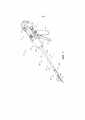
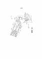
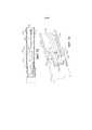
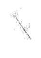
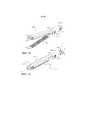
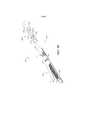
на ФИГ. 1 представлен вид в перспективе варианта осуществления хирургического инструмента и узла удлиненного ствола;in FIG. 1 is a perspective view of an embodiment of a surgical instrument and an elongated trunk assembly;
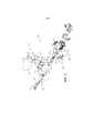
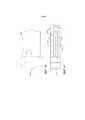
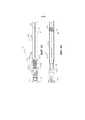
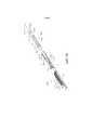
на ФИГ. 2 представлен вид в сборе с пространственным разделением компонентов ручки или участка корпуса хирургического инструмента, показанного на ФИГ. 1;in FIG. 2 is an exploded view of the components of a handle or portion of a surgical instrument body shown in FIG. 1;
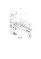
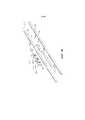
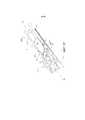
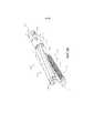
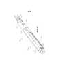
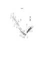
на ФИГ. 3 представлен вид в сборе с пространственным разделением компонентов части узла удлиненного ствола;in FIG. 3 is an exploded view of the components of a portion of an elongated barrel assembly;
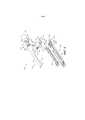
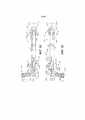
на ФИГ. 4 представлен другой вид в сборе с пространственным разделением компонентов другой части узла удлиненного ствола, показанного на ФИГ. 3;in FIG. 4 is a different exploded view of the components of another part of the elongated barrel assembly shown in FIG. 3;
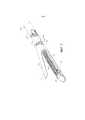
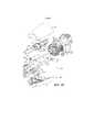
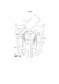
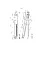
на ФИГ. 5 представлен вид в сборе с пространственным разделением компонентов варианта осуществления части хирургического концевого эффектора и варианта осуществления закрывающей гильзы;in FIG. 5 is an exploded view of the components of an embodiment of a portion of a surgical end effector and an embodiment of a closure sleeve;
на ФИГ. 6 представлен частичный вид в поперечном сечении части конструкции хирургического концевого эффектора и закрывающей гильзы, показанных на ФИГ. 5;in FIG. 6 is a partial cross-sectional view of a portion of the construction of the surgical end effector and the closure sleeve shown in FIG. 5;
на ФИГ. 7 представлен вид в перспективе конструкции хирургического концевого эффектора и закрывающей гильзы, показанных на ФИГ. 5 и 6, с упором в открытом положении или конфигурации;in FIG. 7 is a perspective view of the construction of the surgical end effector and closure sleeve shown in FIG. 5 and 6, with emphasis in the open position or configuration;
на ФИГ. 8 представлен другой вид в перспективе конструкции хирургического концевого эффектора и закрывающей гильзы, показанных на ФИГ. 5-7, с упором в закрытом положении или конфигурации;in FIG. 8 is another perspective view of the construction of the surgical end effector and closure sleeve shown in FIG. 5-7, with emphasis in the closed position or configuration;
На ФИГ. 9 представлен вид в перспективе варианта осуществления хирургического концевого эффектора и узла удлиненного ствола, причем его участки не показаны для ясности;In FIG. 9 is a perspective view of an embodiment of a surgical end effector and an elongated trunk assembly, with portions thereof not shown for clarity;
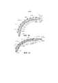
на ФИГ. 10 представлен вид сверху варианта осуществления частей хирургического концевого эффектора и узла удлиненного ствола, показанных на ФИГ. 9, причем хирургический концевой эффектор находится в шарнирно повернутом положении или конфигурации;in FIG. 10 is a top view of an embodiment of parts of a surgical end effector and an elongated trunk assembly shown in FIG. 9, wherein the surgical end effector is in a pivotally rotated position or configuration;
на ФИГ. 11 представлен частичный вид в сборе с пространственным разделением компонентов варианта осуществления частей концевого эффектора и узла удлиненного ствола, показанных на ФИГ. 9 и 10;in FIG. 11 is a partial exploded view of the components of an embodiment of portions of the end effector and the elongated barrel assembly shown in FIG. 9 and 10;
на ФИГ. 12 представлен вид сверху частей хирургического концевого эффектора и узла удлиненного ствола, показанных на ФИГ. 9-11;in FIG. 12 is a plan view of parts of a surgical end effector and an elongated trunk assembly shown in FIG. 9-11;
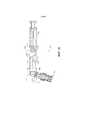
на ФИГ. 13 представлен вид в перспективе варианта осуществления частей хирургического концевого эффектора и узла удлиненного ствола, показанных на ФИГ. 9-12, с хирургическим концевым эффектором в шарнирно повернутом положении или конфигурации;in FIG. 13 is a perspective view of an embodiment of parts of a surgical end effector and an elongated trunk assembly shown in FIG. 9-12, with a surgical end effector in an articulated position or configuration;
на ФИГ. 14 представлен вид сверху варианта осуществления частей хирургического концевого эффектора и узла удлиненного ствола, показанных на ФИГ. 9-13, с хирургическим концевым эффектором в шарнирно повернутой конфигурации, причем некоторые их компоненты для ясности показаны в поперечном сечении;in FIG. 14 is a top view of an embodiment of parts of a surgical end effector and an elongated trunk assembly shown in FIG. 9-13, with a surgical end effector in a pivotally rotated configuration, some of their components are shown in cross section for clarity;
на ФИГ. 15 представлен вид в перспективе другого варианта осуществления части узла удлиненного ствола;in FIG. 15 is a perspective view of another embodiment of a portion of an elongated barrel assembly;
на ФИГ. 16 представлен другой вид в перспективе варианта осуществления узла удлиненного ствола, показанного на ФИГ. 15, причем компоненты закрывающей трубки и закрывающей гильзы не показаны для ясности;in FIG. 16 is another perspective view of an embodiment of an elongated barrel assembly shown in FIG. 15, wherein the components of the closure tube and closure sleeve are not shown for clarity;
на ФИГ. 17 представлен вид сверху варианта осуществления частей узла удлиненного ствола, показанного на ФИГ. 15 и 16;in FIG. 17 is a top view of an embodiment of parts of an elongated barrel assembly shown in FIG. 15 and 16;
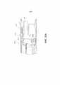
на ФИГ. 18 представлен вид сбоку в вертикальной проекции в поперечном сечении варианта осуществления узла удлиненного ствола, показанного на ФИГ. 15-17, с установленной в участке хирургического концевого эффектора кассетой с хирургическими скобами;in FIG. 18 is a side elevational view in cross section of an embodiment of an elongated barrel assembly shown in FIG. 15-17, with a cassette with surgical staples installed in the area of the surgical end effector;
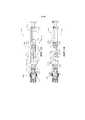
на ФИГ. 19 представлен другой вид сбоку в вертикальной проекции в поперечном сечении узла удлиненного ствола, показанного на ФИГ. 15-18, с установленной в участке хирургического концевого эффектора кассетой с хирургическими скобами;in FIG. 19 is another side elevational view in cross section of an elongated barrel assembly shown in FIG. 15-18, with a cassette with surgical staples installed in the area of the surgical end effector;
на ФИГ. 20 представлен вид сверху частей хирургического концевого эффектора и узла удлиненного ствола, показанных на ФИГ. 15-19, с хирургическим концевым эффектором в шарнирно повернутом положении или конфигурации;in FIG. 20 is a plan view of parts of a surgical end effector and an elongated trunk assembly shown in FIG. 15-19, with a surgical end effector in an articulated position or configuration;
на ФИГ. 20A представлен вид сбоку в вертикальной проекции части другого варианта осуществления хирургического концевого эффектора и закрывающей гильзы;in FIG. 20A is a side elevational view of a portion of another embodiment of a surgical end effector and closure sleeve;
на ФИГ. 21 представлен вид в перспективе другого варианта осуществления хирургического концевого эффектора и узла удлиненного ствола, причем их части не показаны для ясности;in FIG. 21 is a perspective view of another embodiment of a surgical end effector and an elongated trunk assembly, parts thereof not shown for clarity;
на ФИГ. 22 представлен вид в сборе с пространственным разделением компонентов варианта осуществления частей хирургического концевого эффектора и узла удлиненного ствола, показанных на ФИГ. 21;in FIG. 22 is an exploded view of the components of an embodiment of the surgical end effector parts and the elongated trunk assembly shown in FIG. 21;
на ФИГ. 23 представлен вид сверху варианта осуществления частей хирургического концевого эффектора и узла удлиненного ствола, показанных на ФИГ. 21 и 22;in FIG. 23 is a top view of an embodiment of parts of a surgical end effector and an elongated trunk assembly shown in FIG. 21 and 22;
на ФИГ. 24 представлен другой вид сверху варианта осуществления частей хирургического концевого эффектора и узла удлиненного ствола, показанных на ФИГ. 21-23, причем их части не показаны для ясности;in FIG. 24 is another top view of an embodiment of parts of a surgical end effector and an elongated trunk assembly shown in FIG. 21-23, and parts thereof are not shown for clarity;
на ФИГ. 25 представлен другой вид сверху варианта осуществления частей хирургического концевого эффектора и узла удлиненного ствола, показанных на ФИГ. 21-24, с хирургическим концевым эффектором в шарнирно повернутом положении или конфигурации;in FIG. 25 is another top view of an embodiment of parts of a surgical end effector and elongated trunk assembly shown in FIG. 21-24, with a surgical end effector in an articulated position or configuration;
на ФИГ. 26 представлен вид в перспективе с пространственным разделением компонентов другого варианта осуществления части узла удлиненного ствола;in FIG. 26 is an exploded perspective view of another embodiment of a portion of an elongated barrel assembly;
на ФИГ. 27 представлен вид в сборе с пространственным разделением компонентов варианта осуществления частей другого хирургического концевого эффектора и узла удлиненного ствола;in FIG. 27 is an exploded view of the components of an embodiment of parts of another surgical end effector and elongated trunk assembly;
на ФИГ. 28 представлен частичный вид в перспективе варианта осуществления части узла удлиненного ствола, показанного на ФИГ. 27, причем его части не показаны для ясности;in FIG. 28 is a partial perspective view of an embodiment of a portion of the elongated barrel assembly shown in FIG. 27, parts thereof not shown for clarity;
на ФИГ. 29 представлен другой частичный вид в перспективе варианта осуществления частей узла удлиненного ствола, показанного на ФИГ. 27 и 28, причем его части не показаны для ясности;in FIG. 29 is another partial perspective view of an embodiment of parts of an elongated barrel assembly shown in FIG. 27 and 28, parts thereof not shown for clarity;
на ФИГ. 30 представлен другой частичный вид в перспективе варианта осуществления частей узла удлиненного ствола, показанного на ФИГ. 27-29, причем его части не показаны для ясности;in FIG. 30 is another partial perspective view of an embodiment of parts of an elongated barrel assembly shown in FIG. 27-29, with parts thereof not shown for clarity;
на ФИГ. 31 представлен вид сверху варианта осуществления частей хирургического концевого эффектора и узла удлиненного ствола, показанных на ФИГ. 27-30, причем их части не показаны для ясности;in FIG. 31 is a plan view of an embodiment of parts of a surgical end effector and an elongated trunk assembly shown in FIG. 27-30, with parts thereof not shown for clarity;
на ФИГ. 32 представлен другой вид сверху варианта осуществления частей хирургического концевого эффектора и узла удлиненного ствола, показанных на ФИГ. 27-31, причем их части не показаны для ясности, и при этом хирургический концевой эффектор находится в шарнирно повернутом положении или конфигурации;in FIG. 32 is another top view of an embodiment of parts of a surgical end effector and an elongated trunk assembly shown in FIG. 27-31, and parts thereof are not shown for clarity, and wherein the surgical end effector is in an articulated position or configuration;
на ФИГ. 33 представлен вид сбоку в вертикальной проекции варианта осуществления частей хирургического концевого эффектора и узла удлиненного ствола, показанных на ФИГ. 27-32, причем их части не показаны для ясности;in FIG. 33 is a side elevational view of an embodiment of the surgical end effector parts and the elongated trunk assembly shown in FIG. 27-32, and parts thereof are not shown for clarity;
на ФИГ. 34 представлен вид в перспективе варианта осуществления частей хирургического концевого эффектора и узла удлиненного ствола, показанных на ФИГ. 27-33, причем их части не показаны для ясности;in FIG. 34 is a perspective view of an embodiment of parts of a surgical end effector and an elongated trunk assembly shown in FIG. 27-33, and parts thereof are not shown for clarity;
на ФИГ. 35 представлен другой частичный вид в перспективе варианта осуществления частей хирургического концевого эффектора и узла удлиненного ствола, показанных на ФИГ. 27-34, причем их части не показаны для ясности;in FIG. 35 is another partial perspective view of an embodiment of parts of a surgical end effector and an elongated trunk assembly shown in FIG. 27-34, with parts thereof not shown for clarity;
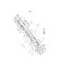
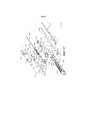
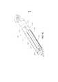
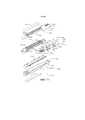
на ФИГ. 36 представлен вид в сборе с пространственным разделением компонентов варианта осуществления частей узла дистальной пусковой штанги и вариантов осуществления бокового несущего элемента;in FIG. 36 is an exploded view of the components of an embodiment of parts of a distal launch rod assembly and embodiments of a lateral carrier;
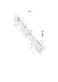
на ФИГ. 37 представлен вид в перспективе узла дистальной пусковой штанги и боковых несущих элементов, показанных на ФИГ. 36;in FIG. 37 is a perspective view of a distal launch rod assembly and side load-bearing elements shown in FIG. 36;
на ФИГ. 38 представлен увеличенный вид в поперечном сечении частей узла дистальной пусковой штанги и боковых несущих элементов, показанных на ФИГ. 36 и 37;in FIG. 38 is an enlarged cross-sectional view of parts of a distal launch rod assembly and side load-bearing elements shown in FIG. 36 and 37;
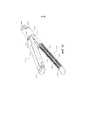
на ФИГ. 39 представлен другой вид в поперечном сечении узла дистальной пусковой штанги и боковых несущих элементов, показанных на ФИГ. 36-38;in FIG. 39 is another cross-sectional view of a distal launch rod assembly and side load-bearing elements shown in FIG. 36-38;
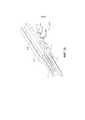
на ФИГ. 40 представлен вид сбоку в вертикальной проекции варианта осуществления части узла дистальной пусковой штанги, прикрепленной к варианту осуществления пускового элемента;in FIG. 40 is a side elevational view of an embodiment of a portion of a distal launch rod assembly attached to an embodiment of a launch element;
на ФИГ. 41 представлен вид сверху варианта осуществления части узла дистальной пусковой штанги и варианта осуществления пускового элемента, показанных на ФИГ. 40;in FIG. 41 is a top view of an embodiment of a portion of a distal launch rod assembly and an embodiment of the launch element shown in FIG. 40;
на ФИГ. 42 представлен вид в поперечном сечении варианта осуществления части узла дистальной пусковой штанги, показанного на ФИГ. 40 и 41, с установленными на него боковыми несущими элементами, причем вариант осуществления узла дистальной пусковой штанги находится в согнутом положении или конфигурации;in FIG. 42 is a cross-sectional view of an embodiment of a portion of a distal launch rod assembly shown in FIG. 40 and 41, with lateral load-bearing elements mounted on it, the embodiment of the distal launch rod assembly being in a bent position or configuration;
на ФИГ. 43 представлен вид в перспективе варианта осуществления узла дистальной пусковой штанги и вариантов осуществления боковых несущих элементов, показанных на ФИГ. 42;in FIG. 43 is a perspective view of an embodiment of a distal launch rod assembly and embodiments of the side load-bearing elements shown in FIG. 42;
на ФИГ. 44 представлен вид в перспективе варианта осуществления частей другого хирургического концевого эффектора и варианта осуществления узла удлиненного ствола, причем их части не показаны для ясности, и при этом хирургический концевой эффектор находится в шарнирно повернутом положении или конфигурации;in FIG. 44 is a perspective view of an embodiment of parts of another surgical end effector and an embodiment of an elongated barrel assembly, parts thereof not shown for clarity, and wherein the surgical end effector is in an articulated position or configuration;
на ФИГ. 45 представлен вид сверху варианта осуществления хирургического концевого эффектора и варианта осуществления узла удлиненного ствола, показанных на ФИГ. 44;in FIG. 45 is a plan view of an embodiment of a surgical end effector and an embodiment of an elongated trunk assembly shown in FIG. 44;
на ФИГ. 46 представлен другой вид сверху варианта осуществления хирургического концевого эффектора и варианта осуществления узла удлиненного ствола, показанных на ФИГ. 45, причем части их шарнирного звена показаны в поперечном сечении;in FIG. 46 is another top view of an embodiment of a surgical end effector and an embodiment of an elongated stem assembly shown in FIG. 45, wherein parts of their articulated link are shown in cross section;
на ФИГ. 47 представлен частичный вид в перспективе другого варианта осуществления частей хирургического концевого эффектора и варианта осуществления узла удлиненного ствола, причем их части не показаны для ясности;in FIG. 47 is a partial perspective view of another embodiment of parts of a surgical end effector and an embodiment of an elongated trunk assembly, parts thereof not shown for clarity;
на ФИГ. 48 представлен вид сверху варианта осуществления частей хирургического концевого эффектора и варианта осуществления узла удлиненного ствола, показанных на ФИГ. 47, причем их части не показаны для ясности;in FIG. 48 is a plan view of an embodiment of parts of a surgical end effector and an embodiment of an elongated trunk assembly shown in FIG. 47, parts thereof not shown for clarity;
на ФИГ. 49 представлен другой вид сверху варианта осуществления хирургического концевого эффектора и варианта осуществления узла удлиненного ствола, показанных на ФИГ. 48;in FIG. 49 is another top view of an embodiment of a surgical end effector and an embodiment of an elongated stem assembly shown in FIG. 48;
на ФИГ. 50 представлен вид сверху в перспективе варианта осуществления частей хирургического концевого эффектора и варианта осуществления узла удлиненного ствола, показанных на ФИГ. 47-49, причем их части не показаны для ясности, и при этом хирургический концевой эффектор находится в шарнирно повернутом положении или конфигурации;in FIG. 50 is a top perspective view of an embodiment of parts of a surgical end effector and an embodiment of an elongated stem assembly shown in FIG. 47-49, their parts not shown for clarity, and the surgical end effector is in a pivotally rotated position or configuration;
на ФИГ. 51 представлен другой вид сверху в перспективе варианта осуществления частей хирургического концевого эффектора и варианта осуществления узла удлиненного ствола, показанных на ФИГ. 50;in FIG. 51 is another top perspective view of an embodiment of surgical end effector parts and an embodiment of an elongated trunk assembly shown in FIG. fifty;
на ФИГ. 52 представлен увеличенный вид в перспективе варианта осуществления частей хирургического концевого эффектора и варианта осуществления узла удлиненного ствола, показанных на ФИГ. 51;in FIG. 52 is an enlarged perspective view of an embodiment of parts of a surgical end effector and an embodiment of an elongated stem assembly shown in FIG. 51;
на ФИГ. 53 представлен вид сверху другого варианта осуществления частей хирургического концевого эффектора и варианта осуществления узла удлиненного ствола, причем их части не показаны для ясности, и при этом хирургический концевой эффектор показан в шарнирно неповернутом положении или конфигурации и в шарнирно повернутом положении или конфигурации;in FIG. 53 is a top view of another embodiment of parts of a surgical end effector and an embodiment of a node of an elongated barrel, parts thereof not shown for clarity, and wherein the surgical end effector is shown in an articulated non-rotated position or configuration and in an articulated rotated position or configuration;
на ФИГ. 54 представлен вид сверху части варианта осуществления узла удлиненного ствола, показанного на ФИГ. 53, с системой шарнирного сочленения в нейтральном или шарнирно не повернутом положении или конфигурации, причем части узла удлиненного ствола удалены для ясности;in FIG. 54 is a plan view of a portion of an embodiment of an elongated barrel assembly shown in FIG. 53, with an articulated joint system in a neutral or pivotally rotated position or configuration, wherein portions of the elongated barrel assembly are removed for clarity;
на ФИГ. 55 представлен другой вид сверху варианта осуществления части узла удлиненного ствола, показанного на ФИГ. 54, с системой шарнирного сочленения в первом шарнирно повернутом положении или конфигурации;in FIG. 55 is another top view of an embodiment of a portion of an elongated stem assembly shown in FIG. 54, with an articulation system in a first articulated position or configuration;
на ФИГ. 56 представлен другой вид сверху варианта осуществления части узла удлиненного ствола, показанного на ФИГ. 54 и 55, с системой шарнирного сочленения во втором шарнирно повернутом положении или конфигурации;in FIG. 56 is another top view of an embodiment of a portion of an elongated stem assembly shown in FIG. 54 and 55, with articulation system in a second articulated position or configuration;
на ФИГ. 57 представлен частичный вид в перспективе другого варианта осуществления частей узла удлиненного ствола, показанного на ФИГ. 53-56, и варианта осуществления частей хирургического концевого эффектора в шарнирно неповернутом положении или конфигурации, причем его части не показаны для ясности;in FIG. 57 is a partial perspective view of another embodiment of parts of an elongated barrel assembly shown in FIG. 53-56, and an embodiment of parts of a surgical end effector in a pivotally untwisted position or configuration, parts thereof not shown for clarity;
на ФИГ. 58 представлен другой частичный вид в перспективе варианта осуществления хирургического концевого эффектора и варианта осуществления узла удлиненного ствола, показанных на ФИГ. 57, причем их части не показаны для ясности;in FIG. 58 is another partial perspective view of an embodiment of a surgical end effector and an embodiment of an elongated stem assembly shown in FIG. 57, parts thereof not shown for clarity;
на ФИГ. 59 представлен вид сверху варианта осуществления части другого узла удлиненного ствола, причем его части не показаны для ясности;in FIG. 59 is a plan view of an embodiment of a portion of another elongated barrel assembly, parts thereof not shown for clarity;
на ФИГ. 60 представлен вид сверху варианта осуществления частей другой системы шарнирного сочленения в нейтральном или шарнирно неповернутом положении;in FIG. 60 is a plan view of an embodiment of parts of another articulation system in a neutral or articulated non-rotated position;
на ФИГ. 61 представлен вид сверху варианта осуществления ведущего диска шарнирного сочленения системы шарнирного сочленения, показанной на ФИГ. 60;in FIG. 61 is a plan view of an embodiment of the articulated drive disc of the articulated system shown in FIG. 60;
на ФИГ. 62 представлен вид сверху варианта осуществления ведомого диска шарнирного сочленения системы шарнирного сочленения, показанной на ФИГ. 60;in FIG. 62 is a plan view of an embodiment of an articulated driven disc of the articulated system shown in FIG. 60;
на ФИГ. 63 представлен другой вид сверху варианта осуществления системы шарнирного сочленения, показанной на ФИГ. 60, в положении или конфигурации после того, как к ней изначально было приложено управляющее движение шарнирного поворота;in FIG. 63 is another top view of an embodiment of the articulation system shown in FIG. 60, in a position or configuration after the control movement of the articulated rotation has been initially applied to it;
на ФИГ. 64 представлен другой вид в поперечном сечении системы шарнирного сочленения, показанной на ФИГ. 63, в шарнирно повернутом положении или конфигурации;in FIG. 64 is another cross-sectional view of the articulation system shown in FIG. 63, in a pivotally rotated position or configuration;
на ФИГ. 65 представлен другой вид сверху варианта осуществления системы шарнирного сочленения, показанной на ФИГ. 63 и 64, во втором шарнирно повернутом положении или конфигурации;in FIG. 65 is another top view of an embodiment of the articulation system shown in FIG. 63 and 64, in a second articulated position or configuration;
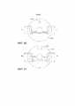
на ФИГ. 66 представлен вид в перспективе другого варианта осуществления хирургического концевого эффектора и закрывающей гильзы с браншами в закрытом положении или конфигурации;in FIG. 66 is a perspective view of another embodiment of a surgical end effector and closure sleeve with branches in a closed position or configuration;
на ФИГ. 67 представлен другой вид в перспективе варианта осуществления хирургического концевого эффектора и закрывающей гильзы, показанных на ФИГ. 66, с браншами в открытом положении или конфигурации;in FIG. 67 is another perspective view of an embodiment of a surgical end effector and closure sleeve shown in FIG. 66, with branches in an open position or configuration;
на ФИГ. 68 представлен вид сбоку в вертикальной проекции варианта осуществления хирургического концевого эффектора и закрывающей гильзы, показанных на ФИГ. 66 и 67, причем закрывающая гильза показана в поперечном сечении, а бранши - в открытом положении или конфигурации;in FIG. 68 is a side elevational view of an embodiment of a surgical end effector and closure sleeve shown in FIG. 66 and 67, the closing sleeve being shown in cross section and the branches in the open position or configuration;
на ФИГ. 69 представлен вид сбоку в вертикальной проекции варианта осуществления хирургического концевого эффектора и закрывающей гильзы, показанных на ФИГ. 66-68, в поперечном сечении и с браншами в открытом положении или конфигурации;in FIG. 69 is a side elevational view of an embodiment of a surgical end effector and closure sleeve shown in FIG. 66-68, in cross section and with branches in an open position or configuration;
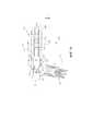
на ФИГ. 70 представлен вид в сборе с пространственным разделением компонентов варианта осуществления хирургического концевого эффектора и закрывающей гильзы, показанных на ФИГ. 66-69;in FIG. 70 is an exploded view of the components of an embodiment of a surgical end effector and closure sleeve shown in FIG. 66-69;
на ФИГ. 71 представлен вид в сборе с пространственным разделением компонентов другого варианта осуществления хирургического концевого эффектора и закрывающей гильзы;in FIG. 71 is an exploded view of the components of another embodiment of a surgical end effector and closure sleeve;
на ФИГ. 72 представлен вид в перспективе другого варианта осуществления хирургического концевого эффектора и закрывающей гильзы с браншами в открытом положении или конфигурации;in FIG. 72 is a perspective view of another embodiment of a surgical end effector and closure sleeve with branches in an open position or configuration;
на ФИГ. 73 представлен другой вид в перспективе варианта осуществления хирургического концевого эффектора и закрывающей гильзы, показанных на ФИГ. 72, с браншами в закрытом положении или конфигурации;in FIG. 73 is another perspective view of an embodiment of a surgical end effector and closure sleeve shown in FIG. 72, with branches in a closed position or configuration;
на ФИГ. 74 представлен вид в перспективе в сборе с пространственным разделением компонентов варианта осуществления хирургического концевого эффектора и закрывающей гильзы, показанных на ФИГ. 72 и 73;in FIG. 74 is an exploded perspective view of the components of an embodiment of a surgical end effector and closure sleeve shown in FIG. 72 and 73;
на ФИГ. 75 представлен вид сбоку в вертикальной проекции варианта осуществления хирургического концевого эффектора и закрывающей гильзы, показанных на ФИГ. 72-74, с браншами в закрытом положении или конфигурации;in FIG. 75 is a side elevational view of an embodiment of a surgical end effector and closure sleeve shown in FIG. 72-74, with branches in a closed position or configuration;
на ФИГ. 76 представлен вид сзади в перспективе варианта осуществления хирургического концевого эффектора, показанного на ФИГ. 72-75, причем вариант осуществления закрывающей гильзы показан для ясности штрих-пунктирными линиями;in FIG. 76 is a rear perspective view of an embodiment of the surgical end effector shown in FIG. 72-75, wherein an embodiment of the closure sleeve is shown for clarity in dashed lines;
на ФИГ. 77 представлен вид сбоку в поперечном сечении варианта осуществления хирургического концевого эффектора и закрывающей гильзы, показанных на ФИГ. 72-76, с браншами в закрытом положении или конфигурации;in FIG. 77 is a side cross-sectional view of an embodiment of a surgical end effector and closure sleeve shown in FIG. 72-76, with branches in a closed position or configuration;
на ФИГ. 78 представлен другой вид сбоку в поперечном сечении, включающий один из вариантов осуществления кулачковых шайб хирургического концевого эффектора и закрывающей гильзы, показанных на ФИГ. 72-77, с браншами в закрытом положении или конфигурации;in FIG. 78 is another cross-sectional side view, including one embodiment of a cam washer of a surgical end effector and a closure sleeve shown in FIG. 72-77, with branches in a closed position or configuration;
на ФИГ. 79 представлен другой вид сбоку в поперечном сечении, включающий один из вариантов осуществления кулачковых шайб хирургического концевого эффектора и закрывающей гильзы, показанных на ФИГ. 72-78, с браншами в открытом положении или конфигурации;in FIG. 79 is another cross-sectional side view, including one embodiment of a cam washer of a surgical end effector and a closure sleeve shown in FIG. 72-78, with branches in the open position or configuration;
на ФИГ. 80 представлен частичный вид в перспективе другого варианта осуществления хирургического концевого эффектора и закрывающей гильзы с браншами в открытом положении или конфигурации;in FIG. 80 is a partial perspective view of another embodiment of a surgical end effector and closure sleeve with branches in an open position or configuration;
на ФИГ. 81 представлен частичный вид в перспективе варианта осуществления хирургического концевого эффектора и закрывающей гильзы, показанных на ФИГ. 80, с браншами в закрытом положении или конфигурации;in FIG. 81 is a partial perspective view of an embodiment of a surgical end effector and closure sleeve shown in FIG. 80, with branches in a closed position or configuration;
на ФИГ. 82 представлен вид в перспективе в сборе хирургического концевого эффектора и варианта осуществления закрывающей гильзы, показанных на ФИГ. 80 и 81;in FIG. 82 is a perspective view of an assembly of a surgical end effector and an embodiment of a closure sleeve shown in FIG. 80 and 81;
на ФИГ. 83 представлен вид сбоку в вертикальной проекции хирургического концевого эффектора и варианта осуществления закрывающей гильзы, показанных на ФИГ. 80-82, с браншами на них в закрытом положении или конфигурации;in FIG. 83 is a side elevational view of a surgical end effector and an embodiment of a closure sleeve shown in FIG. 80-82, with branches on them in the closed position or configuration;
на ФИГ. 84 представлен вид сбоку в вертикальной проекции варианта осуществления хирургического концевого эффектора и закрывающей гильзы, показанных на ФИГ. 80-83, причем часть закрывающей гильзы показана в поперечном сечении, а ее бранши - в открытом положении или конфигурации;in FIG. 84 is a side elevational view of an embodiment of a surgical end effector and closure sleeve shown in FIG. 80-83, with part of the closing sleeve shown in cross section, and its branches in the open position or configuration;
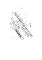
на ФИГ. 85 представлен вид в перспективе в сборе с пространственным разделением компонентов другого варианта осуществления хирургического концевого эффектора и закрывающей гильзы;in FIG. 85 is an exploded perspective view of another embodiment of a surgical end effector and closure sleeve;
на ФИГ. 86 представлен вид сбоку в вертикальной проекции варианта осуществления хирургического концевого эффектора и закрывающей гильзы, показанных на ФИГ. 85, с браншами в закрытом положении или конфигурации;in FIG. 86 is a side elevational view of an embodiment of a surgical end effector and closure sleeve shown in FIG. 85, with branches in a closed position or configuration;
на ФИГ. 87 представлен вид сбоку в вертикальной проекции варианта осуществления хирургического концевого эффектора и закрывающей гильзы, показанных на ФИГ. 85 и 86, с браншами в открытом положении или конфигурации, причем часть закрывающей гильзы показана в поперечном сечении;in FIG. 87 is a side elevational view of an embodiment of a surgical end effector and closure sleeve shown in FIG. 85 and 86, with branches in an open position or configuration, wherein a portion of the closure sleeve is shown in cross section;
на ФИГ. 88 представлен вид в перспективе части другого варианта осуществления узла удлиненного ствола;in FIG. 88 is a perspective view of part of another embodiment of an elongated barrel assembly;
на ФИГ. 89 представлен другой вид в перспективе варианта осуществления узла удлиненного ствола, показанного на ФИГ. 88, с некоторыми компонентами, которые не показаны для ясности;in FIG. 89 is another perspective view of an embodiment of an elongated barrel assembly shown in FIG. 88, with some components that are not shown for clarity;
на ФИГ. 90 представлен другой вид в перспективе узла удлиненного ствола, показанного на ФИГ. 88 и 89, с хирургическим концевым эффектором в шарнирно повернутом положении или конфигурации;in FIG. 90 is another perspective view of an elongated barrel assembly shown in FIG. 88 and 89, with a surgical end effector in an articulated position or configuration;
на ФИГ. 91 представлен вид в сборе с пространственным разделением компонентов узла удлиненного ствола, показанного на ФИГ. 88-90;in FIG. 91 is an exploded perspective view of the components of the elongated barrel assembly shown in FIG. 88-90;
на ФИГ. 92 представлен вид сверху узла удлиненного ствола, показанного на ФИГ. 88-91, причем некоторые компоненты не показаны для ясности, а хирургический концевой эффектор шарнирно повернут в одном направлении;in FIG. 92 is a plan view of an elongated barrel assembly shown in FIG. 88-91, with some components not shown for clarity, and the surgical end effector pivotally rotated in one direction;
на ФИГ. 93 представлен другой вид сверху узла удлиненного ствола, показанного на ФИГ. 88-92, причем некоторые компоненты не показаны для ясности, а хирургический концевой эффектор шарнирно повернут в другом направлении;in FIG. 93 is another top view of an elongated barrel assembly shown in FIG. 88-92, with some components not shown for clarity, and the surgical end effector pivotally rotated in the other direction;
на Фиг. 94 представлен вид в перспективе варианта осуществления кассеты с хирургическими скобами; иin FIG. 94 is a perspective view of an embodiment of a cassette with surgical staples; and
на Фиг. 95 представлен вид в перспективе другого варианта осуществления кассеты с хирургическими скобами.in FIG. 95 is a perspective view of another embodiment of a cassette with surgical staples.
Соответствующие элементы на разных видах обозначаются соответствующими условными обозначениями. Иллюстративные примеры, представленные в данном документе, демонстрируют различные варианты осуществления настоящего изобретения в одной из его форм. Эти иллюстративные примеры не должны истолковываться как ограничивающие объем изобретения.Corresponding elements in different views are indicated by the corresponding symbols. The illustrative examples presented herein demonstrate various embodiments of the present invention in one of its forms. These illustrative examples should not be construed as limiting the scope of the invention.
ПОДРОБНОЕ ОПИСАНИЕDETAILED DESCRIPTION
Заявителю настоящей заявки принадлежат нижеуказанные заявки на патенты, поданные в тот же день, причем каждая из них полностью включена в настоящий документ путем ссылки:The applicant of this application owns the following patent applications filed on the same day, each of which is fully incorporated into this document by reference:
- заявка на патент США № __________, озаглавленная END EFFECTORS WITH DUAL CAM ACTUATED JAW CLOSING FEATURES, досье патентного поверенного № END7677USNP/150112;- US Patent Application No. __________, entitled END EFFECTORS WITH DUAL CAM ACTUATED JAW CLOSING FEATURES, Patent Attorney File No. END7677USNP / 150112;
- заявка на патент США № __________, озаглавленная SURGICAL STAPLING INSTRUMENTS WITH LOCKOUT ARRANGEMENTS FOR PREVENTING FIRING SYSTEM ACTUATION WHEN A CARTRIDGE IS SPENT OR MISSING;досье патентного поверенного № END7676USNP/150111;- US Patent Application No. __________, entitled SURGICAL STAPLING INSTRUMENTS WITH LOCKOUT ARRANGEMENTS FOR PREVENTING FIRING SYSTEM ACTUATION WHEN A CARTRIDGE IS SPENT OR MISSING; Patent Attorney Dossier No. END7676USNP / 150111;
- заявка на патент США № __________, озаглавленная MOVABLE FIRING BEAM SUPPORT ARRANGEMENTS FOR ARTICULATABLE SURGICAL INSTRUMENTS, досье патентного поверенного № END7674USNP/150109;- US Patent Application No. __________ entitled MOVABLE FIRING BEAM SUPPORT ARRANGEMENTS FOR ARTICULATABLE SURGICAL INSTRUMENTS, Patent Attorney Dossier No. END7674USNP / 150109;
- заявка на патент США № __________, озаглавленная ARTICULATABLE SURGICAL INSTRUMENTS WITH COMPOSITE FIRING BEAM STRUCTURES WITH CENTER FIRING SUPPORT MEMBER FOR ARTICULATION SUPPORT, досье патентного поверенного № END7673USNP/150108;- US Patent Application No. __________ entitled ARTICULATABLE SURGICAL INSTRUMENTS WITH COMPOSITE FIRING BEAM STRUCTURES WITH CENTER FIRING SUPPORT MEMBER FOR ARTICULATION SUPPORT, Attorney Dossier No. END7673USNP / 150108;
- заявка на патент США № __________, озаглавленная DUAL ARTICULATION DRIVE SYSTEM ARRANGEMENTS FOR ARTICULATABLE SURGICAL INSTRUMENTS, досье патентного поверенного № END7672USNP/150107; и- US Patent Application No. __________, entitled DUAL ARTICULATION DRIVE SYSTEM ARRANGEMENTS FOR ARTICULATABLE SURGICAL INSTRUMENTS, Patent Attorney File No. END7672USNP / 150107; and
- заявка на патент США № __________, озаглавленная PUSH/PULL ARTICULATION DRIVE SYSTEMS FOR ARTICULATABLE SURGICAL INSTRUMENTS, досье патентного поверенного № END7671USNP/150106.- US Patent Application No. __________, entitled PUSH / PULL ARTICULATION DRIVE SYSTEMS FOR ARTICULATABLE SURGICAL INSTRUMENTS, Patent Attorney Dossier No. END7671USNP / 150106.
Заявителю настоящей заявки принадлежат представленные ниже заявки на патенты, поданные 6 марта 2015 г., каждая из которых полностью включена в настоящий документ путем ссылки:The applicant of this application owns the following patent applications filed March 6, 2015, each of which is fully incorporated into this document by reference:
- заявка на патент США № 14/640,746, озаглавленная POWERED SURGICAL INSTRUMENT;- US patent application No. 14 / 640,746, entitled POWERED SURGICAL INSTRUMENT;
- заявка на патент США № 14/640,795, озаглавленная MULTIPLE LEVEL THRESHOLDS TO MODIFY OPERATION OF POWERED SURGICAL INSTRUMENTS;- US Patent Application No. 14 / 640,795, entitled MULTIPLE LEVEL THRESHOLDS TO MODIFY OPERATION OF POWERED SURGICAL INSTRUMENTS;
- заявка на патент США № 14/640,832, озаглавленная ADAPTIVE TISSUE COMPRESSION TECHNIQUES TO ADJUST CLOSURE RATES FOR MULTIPLE TISSUE TYPES; досье патентного поверенного № END7557USNP/140482;- US Patent Application No. 14 / 640,832, entitled ADAPTIVE TISSUE COMPRESSION TECHNIQUES TO ADJUST CLOSURE RATES FOR MULTIPLE TISSUE TYPES; dossier of the patent attorney No. END7557USNP / 140482;
- заявка на патент США № 14/640,935, озаглавленная OVERLAID MULTI SENSOR RADIO FREQUENCY (RF) ELECTRODE SYSTEM TO MEASURE TISSUE COMPRESSION;U.S. Patent Application No. 14 / 640,935 entitled OVERLAID MULTI SENSOR RADIO FREQUENCY (RF) ELECTRODE SYSTEM TO MEASURE TISSUE COMPRESSION;
- заявка на патент США № 14/640,831, озаглавленная MONITORING SPEED CONTROL AND PRECISION INCREMENTING OF MOTOR FOR POWERED SURGICAL INSTRUMENTS;U.S. Patent Application No. 14 / 640,831, entitled MONITORING SPEED CONTROL AND PRECISION INCREMENTING OF MOTOR FOR POWERED SURGICAL INSTRUMENTS;
- заявка на патент США № 14/640,859, озаглавленная TIME DEPENDENT EVALUATION OF SENSOR DATA TO DETERMINE STABILITY, CREEP, AND VISCOELASTIC ELEMENTS OF MEASURES;U.S. Patent Application No. 14 / 640,859 entitled TIME DEPENDENT EVALUATION OF SENSOR DATA TO DETERMINE STABILITY, CREEP, AND VISCOELASTIC ELEMENTS OF MEASURES;
- заявка на патент США № 14/640,817, озаглавленная INTERACTIVE FEEDBACK SYSTEM FOR POWERED SURGICAL INSTRUMENTS;- US Patent Application No. 14 / 640,817, entitled INTERACTIVE FEEDBACK SYSTEM FOR POWERED SURGICAL INSTRUMENTS;
- заявка на патент США № 14/640,844, озаглавленная CONTROL TECHNIQUES AND SUB-PROCESSOR CONTAINED WITHIN MODULAR SHAFT WITH SELECT CONTROL PROCESSING FROM HANDLE;U.S. Patent Application No. 14 / 640,844, entitled CONTROL TECHNIQUES AND SUB-PROCESSOR CONTAINED WITHIN MODULAR SHAFT WITH SELECT CONTROL PROCESSING FROM HANDLE;
- заявка на патент США № 14/640,837, озаглавленная SMART SENSORS WITH LOCAL SIGNAL PROCESSING;U.S. Patent Application No. 14 / 640,837, entitled SMART SENSORS WITH LOCAL SIGNAL PROCESSING;
- заявка на патент США № 14/640,765, озаглавленная SYSTEM FOR DETECTING THE MIS-INSERTION OF A STAPLE CARTRIDGE INTO A SURGICAL STAPLER;- US Patent Application No. 14 / 640,765 entitled SYSTEM FOR DETECTING THE MIS-INSERTION OF A STAPLE CARTRIDGE INTO A SURGICAL STAPLER;
- заявка на патент США № 14/640,799, озаглавленная SIGNAL AND POWER COMMUNICATION SYSTEM POSITIONED ON A ROTATABLE SHAFT; иU.S. Patent Application No. 14 / 640,799 entitled SIGNAL AND POWER COMMUNICATION SYSTEM POSITIONED ON A ROTATABLE SHAFT; and
- заявка на патент США № 14/640,780, озаглавленная SURGICAL INSTRUMENT COMPRISING A LOCKABLE BATTERY HOUSING.U.S. Patent Application No. 14 / 640,780, entitled SURGICAL INSTRUMENT COMPRISING A LOCKABLE BATTERY HOUSING.
Заявителю настоящей заявки принадлежат представленные ниже заявки на патенты, поданные 27 февраля 2015 г., каждая из которых полностью включена в настоящий документ путем ссылки:The applicant of this application owns the following patent applications filed February 27, 2015, each of which is fully incorporated into this document by reference:
- заявка на патент США № 14/633,576, озаглавленная SURGICAL INSTRUMENT SYSTEM COMPRISING AN INSPECTION STATION;- US patent application No. 14 / 633,576, entitled SURGICAL INSTRUMENT SYSTEM COMPRISING AN INSPECTION STATION;
- заявка на патент США № 14/633,546, озаглавленная SURGICAL APPARATUS CONFIGURED TO ASSESS WHETHER A PERFORMANCE PARAMETER OF THE SURGICAL APPARATUS IS WITHIN AN ACCEPTABLE PERFORMANCE BAND;U.S. Patent Application No. 14 / 633,546, entitled SURGICAL APPARATUS CONFIGURED TO ASSESS WHETHER A PERFORMANCE PARAMETER OF THE SURGICAL APPARATUS IS WITHIN AN ACCEPTABLE PERFORMANCE BAND;
- заявка на патент США № 14/633,576, озаглавленная SURGICAL CHARGING SYSTEM THAT CHARGES AND/OR CONDITIONS ONE OR MORE BATTERIES;U.S. Patent Application No. 14 / 633,576, entitled SURGICAL CHARGING SYSTEM THAT CHARGES AND / OR CONDITIONS ONE OR MORE BATTERIES;
- заявка на патент США № 14/633,566, озаглавленная CHARGING SYSTEM THAT ENABLES EMERGENCY RESOLUTIONS FOR CHARGING A BATTERY;U.S. Patent Application No. 14 / 633,566 entitled CHARGING SYSTEM THAT ENABLES EMERGENCY RESOLUTIONS FOR CHARGING A BATTERY;
- заявка на патент США № 14/633,555, озаглавленная SYSTEM FOR MONITORING WHETHER A SURGICAL INSTRUMENT NEEDS TO BE SERVICED;- US Patent Application No. 14 / 633,555, entitled SYSTEM FOR MONITORING WHETHER A SURGICAL INSTRUMENT NEEDS TO BE SERVICED;
- заявка на патент США № 14/633,542, озаглавленная REINFORCED BATTERY FOR A SURGICAL INSTRUMENT;- US patent application No. 14 / 633,542, entitled REINFORCED BATTERY FOR A SURGICAL INSTRUMENT;
- заявка на патент США № 14/633,548, озаглавленная POWER ADAPTER FOR A SURGICAL INSTRUMENT;- US patent application No. 14 / 633,548, entitled POWER ADAPTER FOR A SURGICAL INSTRUMENT;
- заявка на патент США № 14/633,526, озаглавленная ADAPTABLE SURGICAL INSTRUMENT HANDLE;- US Patent Application No. 14 / 633,526, entitled ADAPTABLE SURGICAL INSTRUMENT HANDLE;
- заявка на патент США № 14/633,541, озаглавленная MODULAR STAPLING ASSEMBLY; и- US patent application No. 14 / 633,541, entitled MODULAR STAPLING ASSEMBLY; and
- заявка на патент США № 14/633,562, озаглавленная SURGICAL APPARATUS CONFIGURED TO TRACK AN END-OF-LIFE PARAMETER.- US patent application No. 14 / 633,562, entitled SURGICAL APPARATUS CONFIGURED TO TRACK AN END-OF-LIFE PARAMETER.
Заявителю настоящей заявки принадлежат нижеуказанные заявки на патенты, поданные 18 декабря 2014 г., каждая из которых полностью включена в настоящий документ путем ссылки:The applicant of this application owns the following patent applications filed December 18, 2014, each of which is fully incorporated into this document by reference:
- заявка на патент США № 14/574,478, озаглавленная SURGICAL INSTRUMENT SYSTEMS COMPRISING AN ARTICULATABLE END EFFECTOR AND MEANS FOR ADJUSTING THE FIRING STROKE OF A FIRING;U.S. Patent Application No. 14 / 574,478 entitled SURGICAL INSTRUMENT SYSTEMS COMPRISING AN ARTICULATABLE END EFFECTOR AND MEANS FOR ADJUSTING THE FIRING STROKE OF A FIRING;
- заявка на патент США № 14/574,483, озаглавленная SURGICAL INSTRUMENT ASSEMBLY COMPRISING LOCKABLE SYSTEMS;- US Patent Application No. 14 / 574,483, entitled SURGICAL INSTRUMENT ASSEMBLY COMPRISING LOCKABLE SYSTEMS;
- заявка на патент США № 14/575,139, озаглавленная DRIVE ARRANGEMENTS FOR ARTICULATABLE SURGICAL INSTRUMENTS;- US patent application No. 14 / 575,139, entitled DRIVE ARRANGEMENTS FOR ARTICULATABLE SURGICAL INSTRUMENTS;
- заявка на патент США № 14/575,148, озаглавленная LOCKING ARRANGEMENTS FOR DETACHABLE SHAFT ASSEMBLIES WITH ARTICULATABLE SURGICAL END EFFECTORS;U.S. Patent Application No. 14 / 575,148 entitled LOCKING ARRANGEMENTS FOR DETACHABLE SHAFT ASSEMBLIES WITH ARTICULATABLE SURGICAL END EFFECTORS;
- заявка на патент США № 14/575,130, озаглавленная SURGICAL INSTRUMENT WITH AN ANVIL THAT IS SELECTIVELY MOVABLE ABOUT A DISCRETE NON-MOVABLE AXIS RELATIVE TO A STAPLE CARTRIDGE;- US Patent Application No. 14 / 575,130, entitled SURGICAL INSTRUMENT WITH AN ANVIL THAT IS SELECTIVELY MOVABLE ABOUT A DISCRETE NON-MOVABLE AXIS RELATIVE TO A STAPLE CARTRIDGE;
- заявка на патент США № 14/575,143, озаглавленная SURGICAL INSTRUMENTS WITH IMPROVED CLOSURE ARRANGEMENTS;U.S. Patent Application No. 14 / 575,143 entitled SURGICAL INSTRUMENTS WITH IMPROVED CLOSURE ARRANGEMENTS;
- заявка на патент США № 14/575,117, озаглавленная SURGICAL INSTRUMENTS WITH ARTICULATABLE END EFFECTORS AND MOVABLE FIRING BEAM SUPPORT ARRANGEMENTS;U.S. Patent Application No. 14 / 575,117, entitled SURGICAL INSTRUMENTS WITH ARTICULATABLE END EFFECTORS AND MOVABLE FIRING BEAM SUPPORT ARRANGEMENTS;
- заявка на патент США № 14/575,154, озаглавленная SURGICAL INSTRUMENTS WITH ARTICULATABLE END EFFECTORS AND IMPROVED FIRING BEAM SUPPORT ARRANGEMENTS;U.S. Patent Application No. 14 / 575,154, entitled SURGICAL INSTRUMENTS WITH ARTICULATABLE END EFFECTORS AND IMPROVED FIRING BEAM SUPPORT ARRANGEMENTS;
- заявка на патент США № 14/574,493, озаглавленная SURGICAL INSTRUMENT ASSEMBLY COMPRISING A FLEXIBLE ARTICULATION SYSTEM; иU.S. Patent Application No. 14 / 574,493 entitled SURGICAL INSTRUMENT ASSEMBLY COMPRISING A FLEXIBLE ARTICULATION SYSTEM; and
- заявка на патент США № 14/574,500, озаглавленная SURGICAL INSTRUMENT ASSEMBLY COMPRISING A LOCKABLE ARTICULATION SYSTEM.- US Patent Application No. 14 / 574,500 entitled SURGICAL INSTRUMENT ASSEMBLY COMPRISING A LOCKABLE ARTICULATION SYSTEM.
Заявителю настоящей заявки принадлежат нижеуказанные заявки на патенты, поданные 1 марта 2013 г., каждая из которых полностью включена в настоящий документ путем ссылки:The applicant of this application owns the following patent applications filed March 1, 2013, each of which is fully incorporated into this document by reference:
- заявка на патент США № 13/782,295, озаглавленная Articulatable Surgical Instruments With Conductive Pathways For Signal Communication, в настоящее время публикация заявки на патент США № 2014/0246471;- US patent application No. 13 / 782,295, entitled Articulatable Surgical Instruments With Conductive Pathways For Signal Communication, currently published US patent application No. 2014/0246471;
- заявка на патент США № 13/782,323, озаглавленная Rotary Powered Articulation Joints For Surgical Instruments, в настоящее время публикация заявки на патент США № 2014/0246472;- US patent application No. 13 / 782,323, entitled Rotary Powered Articulation Joints For Surgical Instruments, currently published US patent application No. 2014/0246472;
- заявка на патент США № 13/782,338, озаглавленная Thumbwheel Switch Arrangements For Surgical Instruments, в настоящее время публикация заявки на патент США № 2014/0249557;- US patent application No. 13 / 782,338, entitled Thumbwheel Switch Arrangements For Surgical Instruments, currently published US patent application No. 2014/0249557;
- заявка на патент США № 13/782,499, озаглавленная Electromechanical Surgical Device with Signal Relay Arrangement, в настоящее время публикация заявки на патент США № 2014/0246474;- US patent application No. 13 / 782,499, entitled Electromechanical Surgical Device with Signal Relay Arrangement, currently publishing US patent application No. 2014/0246474;
- заявка на патент США № 13/782,460, озаглавленная Multiple Processor Motor Control for Modular Surgical Instruments, в настоящее время публикация заявки на патент США № 2014/0246478;- US patent application No. 13 / 782,460, entitled Multiple Processor Motor Control for Modular Surgical Instruments, currently published US patent application No. 2014/0246478;
- заявка на патент США № 13/782,358, озаглавленная Joystick Switch Assemblies For Surgical Instruments, в настоящее время патентная публикация США № 2014/0246477;- US patent application No. 13 / 782,358, entitled Joystick Switch Assemblies For Surgical Instruments, currently US patent publication No. 2014/0246477;
- заявка на патент США № 13/782,481, озаглавленная Sensor Straightened End Effector During Removal Through Trocar, в настоящее время публикация заявки на патент США № 2014/0246479;- US patent application No. 13 / 782,481, entitled Sensor Straightened End Effector During Removal Through Trocar, currently published US patent application No. 2014/0246479;
- заявка на патент США № 13/782,518, озаглавленная Control Methods for Surgical Instruments with Removable Implement Portions, в настоящее время публикация заявки на патент США № 2014/0246475;- US patent application No. 13 / 782,518, entitled Control Methods for Surgical Instruments with Removable Implement Portions, currently published US patent application No. 2014/0246475;
- заявка на патент США № 13/782,375, озаглавленная Rotary Powered Surgical Instruments With Multiple Degrees of Freedom, в настоящее время публикация заявки на патент США № 2014/0246473; и- US patent application No. 13 / 782,375, entitled Rotary Powered Surgical Instruments With Multiple Degrees of Freedom, currently published US patent application No. 2014/0246473; and
- заявка на патент США № 13/782,536, озаглавленная Surgical Instrument Soft Stop, в настоящее время публикация заявки на патент США № 2014/0246476.- US patent application No. 13 / 782,536, entitled Surgical Instrument Soft Stop, currently published US patent application No. 2014/0246476.
Заявителю настоящей заявки также принадлежат нижеуказанные заявки на патенты, поданные 14 марта 2013 г., каждая из которых полностью включена в настоящий документ путем ссылки:The applicant of this application also owns the following patent applications filed March 14, 2013, each of which is fully incorporated into this document by reference:
- заявка на патент США № 13/803,097, озаглавленная ARTICULATABLE SURGICAL INSTRUMENT COMPRISING A FIRING DRIVE, в настоящее время публикация заявки на патент США № 2014/0263542;- US patent application No. 13 / 803,097, entitled ARTICULATABLE SURGICAL INSTRUMENT COMPRISING A FIRING DRIVE, currently published US patent application No. 2014/0263542;
- заявка на патент США № 13/803,193, озаглавленная CONTROL ARRANGEMENTS FOR A DRIVE MEMBER OF A SURGICAL INSTRUMENT, в настоящее время публикация заявки на патент США № 2014/0263537;- US patent application No. 13 / 803,193, entitled CONTROL ARRANGEMENTS FOR A DRIVE MEMBER OF A SURGICAL INSTRUMENT, currently published US patent application No. 2014/0263537;
- заявка на патент США № 13/803,053, озаглавленная INTERCHANGEABLE SHAFT ASSEMBLIES FOR USE WITH A SURGICAL INSTRUMENT, в настоящее время публикация заявки на патент США № 2014/0263564;- US patent application No. 13 / 803,053, entitled INTERCHANGEABLE SHAFT ASSEMBLIES FOR USE WITH A SURGICAL INSTRUMENT, currently published US patent application No. 2014/0263564;
- заявка на патент США № 13/803,086, озаглавленная ARTICULATABLE SURGICAL INSTRUMENT COMPRISING AN ARTICULATION LOCK, в настоящее время публикация заявки на патент США № 2014/0263541;- US patent application No. 13 / 803,086, entitled ARTICULATABLE SURGICAL INSTRUMENT COMPRISING AN ARTICULATION LOCK, currently published US patent application No. 2014/0263541;
- заявка на патент США № 13/803,210, озаглавленная SENSOR ARRANGEMENTS FOR ABSOLUTE POSITIONING SYSTEM FOR SURGICAL INSTRUMENTS, в настоящее время публикация заявки на патент США № 2014/0263538;- US patent application No. 13 / 803,210 entitled SENSOR ARRANGEMENTS FOR ABSOLUTE POSITIONING SYSTEM FOR SURGICAL INSTRUMENTS, currently published US patent application No. 2014/0263538;
- заявка на патент США № 13/803,148, озаглавленная MULTI-FUNCTION MOTOR FOR A SURGICAL INSTRUMENT, в настоящее время публикация заявки на патент США № 2014/0263554;- US patent application No. 13 / 803,148, entitled MULTI-FUNCTION MOTOR FOR A SURGICAL INSTRUMENT, currently published US patent application No. 2014/0263554;
- заявка на патент США № 13/803,066, озаглавленная DRIVE SYSTEM LOCKOUT ARRANGEMENTS FOR MODULAR SURGICAL INSTRUMENTS, в настоящее время публикация заявки на патент США № 2014/0263565;- US patent application No. 13 / 803,066, entitled DRIVE SYSTEM LOCKOUT ARRANGEMENTS FOR MODULAR SURGICAL INSTRUMENTS, currently published US patent application No. 2014/0263565;
- заявка на патент США № 13/803,117, озаглавленная ARTICULATION CONTROL SYSTEM FOR ARTICULATABLE SURGICAL INSTRUMENTS, в настоящее время публикация заявки на патент США № 2014/0263553;- US patent application No. 13 / 803,117, entitled ARTICULATION CONTROL SYSTEM FOR ARTICULATABLE SURGICAL INSTRUMENTS, currently published US patent application No. 2014/0263553;
- заявка на патент США № 13/803,130, озаглавленная DRIVE TRAIN CONTROL ARRANGEMENTS FOR MODULAR SURGICAL INSTRUMENTS, в настоящее время публикация заявки на патент США № 2014/0263543; и- US patent application No. 13 / 803,130, entitled DRIVE TRAIN CONTROL ARRANGEMENTS FOR MODULAR SURGICAL INSTRUMENTS, currently published US patent application No. 2014/0263543; and
- заявка на патент США № 13/803,159, озаглавленная METHOD AND SYSTEM FOR OPERATING A SURGICAL INSTRUMENT, в настоящее время публикация заявки на патент США № 2014/0277017.- US patent application No. 13 / 803,159, entitled METHOD AND SYSTEM FOR OPERATING A SURGICAL INSTRUMENT, currently published US patent application No. 2014/0277017.
Заявителю настоящей заявки принадлежит представленная ниже заявка на патент, поданная 7 марта 2014 г., которая полностью включена в настоящий документ путем ссылки:The applicant of this application owns the patent application below, filed March 7, 2014, which is fully incorporated herein by reference:
- заявка на патент США № 14/200,111, озаглавленная CONTROL SYSTEMS FOR SURGICAL INSTRUMENTS, в настоящее время публикация заявки на патент США № 2014/0263539.- US patent application No. 14 / 200,111, entitled CONTROL SYSTEMS FOR SURGICAL INSTRUMENTS, currently published US patent application No. 2014/0263539.
Заявителю настоящей заявки принадлежат нижеуказанные заявки на патенты, поданные 26 марта 2014 г., каждая из которых полностью включена в настоящий документ путем ссылки:The applicant of the present application owns the following patent applications filed March 26, 2014, each of which is fully incorporated into this document by reference:
- заявка на патент США № 14/226,106, озаглавленная POWER MANAGEMENT CONTROL SYSTEMS FOR SURGICAL INSTRUMENTS;- US Patent Application No. 14 / 226.106, entitled POWER MANAGEMENT CONTROL SYSTEMS FOR SURGICAL INSTRUMENTS;
- заявка на патент США № 14/226,099, озаглавленная STERILIZATION VERIFICATION CIRCUIT;U.S. Patent Application No. 14 / 226,099, entitled STERILIZATION VERIFICATION CIRCUIT;
- заявка на патент США № 14/226,094, озаглавленная VERIFICATION OF NUMBER OF BATTERY EXCHANGES/PROCEDURE COUNT;U.S. Patent Application No. 14 / 226,094, entitled VERIFICATION OF NUMBER OF BATTERY EXCHANGES / PROCEDURE COUNT;
- заявка на патент США № 14/226,117, озаглавленная POWER MANAGEMENT THROUGH SLEEP OPTIONS OF SEGMENTED CIRCUIT AND WAKE UP CONTROL;U.S. Patent Application No. 14 / 226,117 entitled POWER MANAGEMENT THROUGH SLEEP OPTIONS OF SEGMENTED CIRCUIT AND WAKE UP CONTROL;
- заявка на патент США № 14/226,075, озаглавленная MODULAR POWERED SURGICAL INSTRUMENT WITH DETACHABLE SHAFT ASSEMBLIES;U.S. Patent Application No. 14 / 226,075 entitled MODULAR POWERED SURGICAL INSTRUMENT WITH DETACHABLE SHAFT ASSEMBLIES;
- заявка на патент США № 14/226,093, озаглавленная FEEDBACK ALGORITHMS FOR MANUAL BAILOUT SYSTEMS FOR SURGICAL INSTRUMENTS;U.S. Patent Application No. 14 / 226,093, entitled FEEDBACK ALGORITHMS FOR MANUAL BAILOUT SYSTEMS FOR SURGICAL INSTRUMENTS;
- заявка на патент США № 14/226,116, озаглавленная SURGICAL INSTRUMENT UTILIZING SENSOR ADAPTATION;- US Patent Application No. 14 / 226,116, entitled SURGICAL INSTRUMENT UTILIZING SENSOR ADAPTATION;
- заявка на патент США № 14/226,071, озаглавленная SURGICAL INSTRUMENT CONTROL CIRCUIT HAVING A SAFETY PROCESSOR;U.S. Patent Application No. 14 / 226,071 entitled SURGICAL INSTRUMENT CONTROL CIRCUIT HAVING A SAFETY PROCESSOR;
- заявка на патент США № 14/226,097, озаглавленная SURGICAL INSTRUMENT COMPRISING INTERACTIVE SYSTEMS;- US Patent Application No. 14 / 226,097, entitled SURGICAL INSTRUMENT COMPRISING INTERACTIVE SYSTEMS;
- заявка на патент США № 14/226,126, озаглавленная INTERFACE SYSTEMS FOR USE WITH SURGICAL INSTRUMENTS;U.S. Patent Application No. 14 / 226,126 entitled INTERFACE SYSTEMS FOR USE WITH SURGICAL INSTRUMENTS;
- заявка на патент США № 14/226,133, озаглавленная MODULAR SURGICAL INSTRUMENT SYSTEM;- US Patent Application No. 14 / 226,133, entitled MODULAR SURGICAL INSTRUMENT SYSTEM;
- заявка на патент США № 14/226,081, озаглавленная SYSTEMS AND METHODS FOR CONTROLLING A SEGMENTED CIRCUIT;U.S. Patent Application No. 14 / 226,081 entitled SYSTEMS AND METHODS FOR CONTROLLING A SEGMENTED CIRCUIT;
- заявка на патент США № 14/226,076, озаглавленная POWER MANAGEMENT THROUGH SEGMENTED CIRCUIT AND VARIABLE VOLTAGE PROTECTION;U.S. Patent Application No. 14 / 226.076 entitled POWER MANAGEMENT THROUGH SEGMENTED CIRCUIT AND VARIABLE VOLTAGE PROTECTION;
- заявка на патент США № 14/226,111, озаглавленная SURGICAL STAPLING INSTRUMENT SYSTEM; и- US Patent Application No. 14 / 226,111, entitled SURGICAL STAPLING INSTRUMENT SYSTEM; and
- заявка на патент США № 14/226,125, озаглавленная SURGICAL INSTRUMENT COMPRISING A ROTATABLE SHAFT.- US patent application No. 14 / 226,125, entitled SURGICAL INSTRUMENT COMPRISING A ROTATABLE SHAFT.
Заявителю настоящей заявки также принадлежат нижеуказанные заявки на патенты, поданные 5 сентября 2014 г., каждая из которых полностью включена в настоящий документ путем ссылки:The applicant of this application also owns the following patent applications filed September 5, 2014, each of which is fully incorporated into this document by reference:
- заявка на патент США № 14/479,103, озаглавленная CIRCUITRY AND SENSORS FOR POWERED MEDICAL DEVICE;U.S. Patent Application No. 14 / 479,103 entitled CIRCUITRY AND SENSORS FOR POWERED MEDICAL DEVICE;
- заявка на патент США № 14/479,119, озаглавленная ADJUNCT WITH INTEGRATED SENSORS TO QUANTIFY TISSUE COMPRESSION;- US patent application No. 14 / 479,119, entitled ADJUNCT WITH INTEGRATED SENSORS TO QUANTIFY TISSUE COMPRESSION;
- заявка на патент США № 14/478,908, озаглавленная MONITORING DEVICE DEGRADATION BASED ON COMPONENT EVALUATION;- US patent application No. 14 / 478,908, entitled MONITORING DEVICE DEGRADATION BASED ON COMPONENT EVALUATION;
- заявка на патент США № 14/478,895, озаглавленная MULTIPLE SENSORS WITH ONE SENSOR AFFECTING A SECOND SENSOR'S OUTPUT OR INTERPRETATION;- US Patent Application No. 14 / 478,895, entitled MULTIPLE SENSORS WITH ONE SENSOR AFFECTING A SECOND SENSOR'S OUTPUT OR INTERPRETATION;
- заявка на патент США № 14/479,110, озаглавленная USE OF POLARITY OF HALL MAGNET DETECTION TO DETECT MISLOADED CARTRIDGE;U.S. Patent Application No. 14 / 479,110 entitled USE OF POLARITY OF HALL MAGNET DETECTION TO DETECT MISLOADED CARTRIDGE;
- заявка на патент США № 14/479,098, озаглавленная SMART CARTRIDGE WAKE UP OPERATION AND DATA RETENTION;U.S. Patent Application No. 14 / 479,098 entitled SMART CARTRIDGE WAKE UP OPERATION AND DATA RETENTION;
- заявка на патент США № 14/479,115, озаглавленная MULTIPLE MOTOR CONTROL FOR POWERED MEDICAL DEVICE; иU.S. Patent Application No. 14 / 479,115 entitled MULTIPLE MOTOR CONTROL FOR POWERED MEDICAL DEVICE; and
- заявка на патент США № 14/479,108, озаглавленная LOCAL DISPLAY OF TISSUE PARAMETER STABILIZATION.- US Patent Application No. 14 / 479.108 entitled LOCAL DISPLAY OF TISSUE PARAMETER STABILIZATION.
Заявителю настоящей заявки также принадлежат нижеуказанные заявки на патенты, поданные 9 апреля 2014 г., каждая из которых полностью включена в настоящий документ путем ссылки:The applicant of this application also owns the following patent applications filed April 9, 2014, each of which is fully incorporated into this document by reference:
- заявка на патент США № 14/248,590, озаглавленная MOTOR DRIVEN SURGICAL INSTRUMENTS WITH LOCKABLE DUAL DRIVE SHAFTS, в настоящее время публикация заявки на патент США № 2014/0305987;- US patent application No. 14 / 248,590, entitled MOTOR DRIVEN SURGICAL INSTRUMENTS WITH LOCKABLE DUAL DRIVE SHAFTS, currently published US patent application No. 2014/0305987;
- заявка на патент США № 14/248,581, озаглавленная SURGICAL INSTRUMENT COMPRISING A CLOSING DRIVE AND A FIRING DRIVE OPERATED FROM THE SAME ROTATABLE OUTPUT, в настоящее время публикация заявки на патент США № 2014/0305989;- US Patent Application No. 14 / 248,581, entitled SURGICAL INSTRUMENT COMPRISING A CLOSING DRIVE AND A FIRING DRIVE OPERATED FROM THE SAME ROTATABLE OUTPUT, currently published US patent application No. 2014/0305989;
- заявка на патент США № 14/248,595, озаглавленная SURGICAL INSTRUMENT SHAFT INCLUDING SWITCHES FOR CONTROLLING THE OPERATION OF THE SURGICAL INSTRUMENT, в настоящее время публикация заявки на патент США № 2014/0305988;- US patent application No. 14 / 248,595, entitled SURGICAL INSTRUMENT SHAFT INCLUDING SWITCHES FOR CONTROLLING THE OPERATION OF THE SURGICAL INSTRUMENT, currently published US patent application No. 2014/0305988;
- заявка на патент США № 14/248,588, озаглавленная POWERED LINEAR SURGICAL STAPLER, в настоящее время публикация заявки на патент США № 2014/0309666;- US patent application No. 14 / 248,588, entitled POWERED LINEAR SURGICAL STAPLER, currently published US patent application No. 2014/0309666;
- заявка на патент США № 14/248,591, озаглавленная TRANSMISSION ARRANGEMENT FOR A SURGICAL INSTRUMENT, в настоящее время публикация заявки на патент США № 2014/0305991;- US patent application No. 14 / 248,591, entitled TRANSMISSION ARRANGEMENT FOR A SURGICAL INSTRUMENT, currently published US patent application No. 2014/0305991;
- заявка на патент США 14/248,584, озаглавленная MODULAR MOTOR DRIVEN SURGICAL INSTRUMENTS WITH ALIGNMENT FEATURES FOR ALIGNING ROTARY DRIVE SHAFTS WITH SURGICAL END EFFECTOR SHAFTS, в настоящее время публикация заявки на патент США № 2014/0305994;-
- заявка на патент США № 14/248,587, озаглавленная POWERED SURGICAL STAPLER, в настоящее время публикация заявки на патент США № 2014/0309665;- US patent application No. 14 / 248,587, entitled POWERED SURGICAL STAPLER, currently published US patent application No. 2014/0309665;
- заявка на патент США № 14/248,586, озаглавленная DRIVE SYSTEM DECOUPLING ARRANGEMENT FOR A SURGICAL INSTRUMENT, в настоящее время публикация заявки на патент США № 2014/0305990; и- US patent application No. 14 / 248,586, entitled DRIVE SYSTEM DECOUPLING ARRANGEMENT FOR A SURGICAL INSTRUMENT, currently published US patent application No. 2014/0305990; and
- заявка на патент США № 14/248,607, озаглавленная MODULAR MOTOR DRIVEN SURGICAL INSTRUMENTS WITH STATUS INDICATION ARRANGEMENTS, в настоящее время публикация заявки на патент США № 2014/0305992.U.S. Patent Application No. 14 / 248,607 entitled MODULAR MOTOR DRIVEN SURGICAL INSTRUMENTS WITH STATUS INDICATION ARRANGEMENTS, currently published U.S. Patent Application No. 2014/0305992.
Заявителю настоящей заявки также принадлежат нижеуказанные заявки на патенты, поданные 16 апреля 2013 г., каждая из которых полностью включена в настоящий документ путем ссылки:The applicant of this application also owns the following patent applications filed April 16, 2013, each of which is fully incorporated into this document by reference:
- предварительная заявка на патент США № 61/812,365, озаглавленная SURGICAL INSTRUMENT WITH MULTIPLE FUNCTIONS PERFORMED BY A SINGLE MOTOR;- provisional application for US patent No. 61 / 812,365, entitled SURGICAL INSTRUMENT WITH MULTIPLE FUNCTIONS PERFORMED BY A SINGLE MOTOR;
- предварительная заявка на патент США № 61/812,376, озаглавленная LINEAR CUTTER WITH POWER;- provisional application for US patent No. 61 / 812,376, entitled LINEAR CUTTER WITH POWER;
- предварительная заявка на патент США № 61/812,382, озаглавленная LINEAR CUTTER WITH MOTOR AND PISTOL GRIP;- provisional application for US patent No. 61 / 812,382, entitled LINEAR CUTTER WITH MOTOR AND PISTOL GRIP;
- предварительная заявка на патент США № 61/812,385, озаглавленная SURGICAL INSTRUMENT HANDLE WITH MULTIPLE ACTUATION MOTORS AND MOTOR CONTROL; и- provisional application for US patent No. 61 / 812,385, entitled SURGICAL INSTRUMENT HANDLE WITH MULTIPLE ACTUATION MOTORS AND MOTOR CONTROL; and
- предварительная заявка на патент США № 61/812,372, озаглавленная SURGICAL INSTRUMENT WITH MULTIPLE FUNCTIONS PERFORMED BY A SINGLE MOTOR.- provisional application for US patent No. 61 / 812,372, entitled SURGICAL INSTRUMENT WITH MULTIPLE FUNCTIONS PERFORMED BY A SINGLE MOTOR.
В настоящем документе приведены подробные сведения, необходимые для понимания общей конструкции, функциональности, особенностей изготовления и применения различных вариантов осуществления, описание которых предоставлено в спецификации и проиллюстрировано сопроводительными чертежами. Хорошо известные принципы работы, компоненты и элементы не получили в настоящем документе подробного описания, чтобы не затруднять понимание вариантов осуществления, описанных в спецификации. Читатель должен понимать, что варианты осуществления, описанные и проиллюстрированные в настоящем документе, являются не имеющими ограничительного характера примерами. Следует понимать, что определенные конструктивные и функциональные особенности, описанные в данном документе, могут иметь показательный или пояснительный характер. Изменения и модификации вариантов осуществления, описанных и проиллюстрированных в данном документе, могут выполняться в пределах объема формулы изобретения.This document provides the detailed information necessary to understand the overall design, functionality, manufacturing features and application of various embodiments, the description of which is provided in the specification and illustrated in the accompanying drawings. Well-known operating principles, components, and elements have not received a detailed description in this document so as not to obscure the embodiments described in the specification. The reader should understand that the embodiments described and illustrated herein are non-limiting examples. It should be understood that certain design and functional features described in this document may be indicative or explanatory. Changes and modifications to the embodiments described and illustrated herein may be made within the scope of the claims.
Термины «содержать» (и любые его формы, такие как «содержит» и «содержащий»), «иметь» (и любые его формы, такие как «имеет» и «имеющий»), «включать» (и любые его формы, такие как «включает» и «включающий»), «вмещать» (и любые его формы, такие как «вмещает» и «вмещающий») представляют собой неограниченные связующие глаголы. В результате, хирургическая система или устройство, которое «содержит», «имеет», «включает» или «вмещает» один или более элементов, обладает этим одним или более элементами, но обладание не ограничивается только этим одним или более элементами. Аналогично элемент системы или устройства, который «содержит», «имеет», «включает» или «вмещает» один или более элементов, обладает этим одним или более элементами, но обладание не ограничивается только этим одним или более элементами.The terms “contain” (and any of its forms, such as “contains” and “containing”), “have” (and any of its forms, such as “has” and “having”), “include” (and any of its forms, such as “includes” and “including”), “contain” (and any of its forms, such as “holds” and “containing”) are unlimited connecting verbs. As a result, a surgical system or device that "contains," "has," "includes," or "accommodates" one or more elements has this one or more elements, but possession is not limited to only one or more elements. Similarly, an element of a system or device that “contains”, “has”, “includes” or “accommodates” one or more elements has this one or more elements, but possession is not limited to only one or more elements.
Термины «проксимальный» и «дистальный» в настоящем документе определяются относительно врача, управляющего рукояткой хирургического инструмента. Термин «проксимальный» относится к участку, расположенному ближе всего к врачу, а термин «дистальный» относится к участку, удаленному от врача. Предлагается также для удобства и ясности применительно к рисункам использовать в настоящем документе такие пространственные термины, как «вертикальный», «горизонтальный», «вверх» и «вниз». Тем не менее, поскольку использование хирургических инструментов предполагает множество ориентаций и положений, указанные термины не следует толковать как ограничивающие и (или) абсолютные.The terms “proximal” and “distal” are used herein to refer to the physician controlling the handle of a surgical instrument. The term "proximal" refers to the area closest to the doctor, and the term "distal" refers to the area remote from the doctor. It is also proposed to use spatial terms such as “vertical”, “horizontal”, “up” and “down” in relation to the drawings for convenience and clarity. However, since the use of surgical instruments involves many orientations and provisions, these terms should not be interpreted as limiting and (or) absolute.
Для выполнения лапароскопических и минимально инвазивных хирургических вмешательств предложены различные примеры устройств и способов. Однако читателю будет вполне понятно, что различные способы и устройства, описанные в настоящем документе, можно применять в множестве хирургических вмешательств и сфер применения, включая, например, те, что связаны открытыми оперативными вмешательствами. По ходу данного подробного описания читатель сможет дополнительно оценить, что разнообразные инструменты, описанные в данном документе, можно вводить в тело любым способом - как через естественные отверстия, так и через разрез или пункционное отверстие, проделанное в тканях, и т.п. Рабочие части или части концевых эффекторов таких инструментов можно вводить непосредственно в тело пациента или через устройство доступа, которое имеет рабочий канал, через который можно проводить концевой эффектор и удлиненный ствол хирургического инструмента.To perform laparoscopic and minimally invasive surgical interventions, various examples of devices and methods have been proposed. However, the reader will be quite clear that the various methods and devices described herein can be used in many surgical interventions and fields of application, including, for example, those associated with open surgical interventions. In the course of this detailed description, the reader will be able to further appreciate that the various tools described in this document can be introduced into the body in any way - either through natural openings, or through an incision or a puncture hole made in the tissues, etc. The working parts or parts of the end effectors of such instruments can be inserted directly into the patient’s body or through an access device that has a working channel through which the end effector and the elongated shaft of the surgical instrument can be passed.
Хирургическая сшивающая система может содержать ствол и концевой проходящий от ствола эффектор. Концевой эффектор может включать первую браншу и вторую браншу. Первая бранша содержит кассету со скобами. Кассета со скобами выполнена с возможностью вставки в первую браншу и удаления из нее; однако предусмотрены другие варианты осуществления, в которых кассета со скобами выполнена без возможности извлечения из первой бранши или, по меньшей мере, выполнена с возможностью быстрой замены из первой бранши. Вторая бранша содержит упор, выполненный с возможностью деформации скоб, выталкиваемых из кассеты со скобами. Вторая бранша выполнена с возможностью поворота относительно первой бранши вокруг оси закрытия; однако предусмотрены другие варианты осуществления, в которых первая бранша выполнена с возможностью поворота относительно второй бранши. Хирургическая сшивающая система дополнительно содержит шарнирное сочленение, выполненное с возможностью обеспечения вращения или шарнирного поворота концевого эффектора относительно ствола. Концевой эффектор выполнен с возможностью вращения вокруг оси шарнирного сочленения, проходящей через шарнирное сочленение. Предусмотрены другие варианты осуществления, которые не включают шарнирное сочленение.A surgical stapling system may include a trunk and an end effector extending from the trunk. The end effector may include a first branch and a second branch. The first branch contains a cassette with staples. The cassette with brackets is configured to be inserted into the first jaw and removed from it; however, other embodiments are provided in which the cassette with brackets is made without being able to be removed from the first jaw, or at least configured to be quickly replaced from the first jaw. The second branch contains an emphasis made with the possibility of deformation of the brackets ejected from the cartridge with brackets. The second jaw is rotatable relative to the first jaw around the axis of closure; however, other embodiments are provided in which the first jaw is rotatable relative to the second jaw. The surgical stapling system further comprises an articulation configured to provide rotation or articulation of the end effector relative to the barrel. The end effector is rotatable around the axis of the articulation passing through the articulation. Other embodiments are provided that do not include articulation.
Кассета со скобами содержит корпус кассеты. Корпус кассеты включает проксимальный конец, дистальный конец и платформу, проходящую между проксимальным концом и дистальным концом. В процессе применения кассета со скобами расположена на первой стороне ткани, подлежащей сшиванию, а упор расположен на второй стороне ткани. Упор перемещается к кассете со скобами для сжатия и прижимания ткани к платформе. После этого скобы, хранящиеся в корпусе кассеты с возможностью извлечения, можно размещать в ткани. Корпус кассеты включает сформированные в нем полости для скоб, при этом скобы хранятся в полостях для скоб с возможностью извлечения. Полости для скоб расположены в шесть продольных рядов. Три ряда полостей для скоб расположены на первой стороне продольного паза, и три ряда полостей для скоб расположены на второй стороне продольного паза. Возможны другие конструкции скоб и полостей для скоб.The cassette with brackets contains the cassette body. The cartridge case includes a proximal end, a distal end and a platform extending between the proximal end and the distal end. During use, the cassette with staples is located on the first side of the fabric to be stitched, and the emphasis is located on the second side of the fabric. The emphasis moves to the cartridge with brackets for compression and pressing of fabric to a platform. After that, the staples stored in the cassette with the possibility of extraction can be placed in the fabric. The cassette body includes the brackets formed in it, while the brackets are stored in the brackets for retrieval. Cavities for brackets are located in six longitudinal rows. Three rows of cavity for the brackets are located on the first side of the longitudinal groove, and three rows of cavity for the brackets are located on the second side of the longitudinal groove. Other constructions of staples and cavities for staples are possible.
В корпусе кассеты скобы поддерживаются с помощью выталкивателей скоб. Выталкиватели выполнены с возможностью перемещения между первым или неактивированным положением и вторым или активированным положением для выталкивания скоб из полостей для скоб. Выталкиватели удерживаются в корпусе кассеты с помощью фиксатора, который проходит вокруг нижней части корпуса кассеты и включает упругие элементы, выполненные с возможностью захвата корпуса кассеты и удерживания фиксатора относительно корпуса кассеты. Выталкиватели выполнены с возможностью перемещения между их неактивированными положениями и активированными положениями с помощью салазок. Салазки выполнены с возможностью перемещения между проксимальным положением, смежным с проксимальным концом, и дистальным положением, смежным с дистальным концом. Салазки содержат множество наклонных поверхностей, выполненных с возможностью скольжения под выталкивателями и подъема выталкивателей и поддерживаемых на них скоб к упору.In the cassette case, the brackets are supported using ejector brackets. The ejectors are arranged to move between the first or inactive position and the second or activated position to eject the brackets from the cavity for the brackets. The pushers are held in the cassette body by means of a latch that extends around the lower part of the cassette body and includes elastic elements capable of gripping the cassette body and holding the latch relative to the cassette body. The pushers are arranged to move between their inactive positions and activated positions using a slide. The slide is movable between a proximal position adjacent to the proximal end and a distal position adjacent to the distal end. The slide contains many inclined surfaces made with the possibility of sliding under the ejectors and lifting the ejectors and the brackets supported on them to the stop.
В дополнение к указанному выше, салазки перемещаются дистально с помощью пускового элемента. Пусковой элемент выполнен с возможностью контакта с салазками и проталкивания салазок к дистальному концу. Продольный паз, сформированный в корпусе кассеты, выполнен с возможностью приема пускового элемента. Упор также включает паз, выполненный с возможностью приема пускового элемента. Пусковой элемент дополнительно содержит первый кулачок, который взаимодействует с первой браншей, и второй кулачок, который взаимодействует со второй браншей. При выдвижении пускового элемента дистально первый кулачок и второй кулачок позволяют контролировать расстояние, или тканевый зазор, между платформой кассеты со скобами и упором. Пусковой элемент также содержит скальпель, выполненный с возможностью рассечения ткани, захваченной между кассетой со скобами и упором. Желательно, по меньшей мере, частично располагать скальпель проксимально по отношению к наклонным поверхностям таким образом, чтобы скобы выталкивались раньше скальпеля.In addition to the above, the slide moves distally with a trigger element. The trigger element is made with the possibility of contact with the slide and pushing the slide to the distal end. A longitudinal groove formed in the cassette body is configured to receive a trigger element. The emphasis also includes a groove configured to receive a trigger element. The trigger element further comprises a first cam that interacts with the first jaw and a second cam that interacts with the second jaw. When extending the trigger element distally, the first cam and the second cam allow you to control the distance, or tissue gap, between the cassette platform with brackets and emphasis. The trigger element also contains a scalpel, made with the possibility of dissection of tissue captured between the cassette with brackets and emphasis. It is desirable to at least partially position the scalpel proximal to the inclined surfaces so that the braces are pushed out before the scalpel.
На ФИГ. 1-4 представлен хирургический режущий и сшивающий инструмент с двигателем 10, который может использоваться или не использоваться многократно. В показанном варианте осуществления хирургический инструмент 10 имеет корпус 12, который содержит ручку 14, выполненную с возможностью захвата, манипулирования и активирования врачом. Корпус 12 выполнен с возможностью функционального крепления к узлу 200 удлиненного ствола, который имеет функционально связанный с ним концевой эффектор 300, который выполнен с возможностью выполнения одной или более хирургических задач или вмешательств. Узел 200 удлиненного ствола может быть взаимозаменяемым с другими узлами ствола в различных способах, описанных, например, в заявке на патент США № 14/226,075, озаглавленной MODULAR POWERED SURGICAL INSTRUMENT WITH DETACHABLE SHAFT ASSEMBLIES, содержание которой полностью включено в настоящий документ путем ссылки. В других конструкциях узел удлиненного ствола может не быть взаимозаменяемым с другими узлами ствола и по существу представляет собой специальную несъемную часть инструмента.In FIG. 1-4, a surgical cutting and stapling instrument with an
По мере изучения настоящего подробного описания будет понятно, что формы сменных узлов ствола, описанные в настоящем документе, также могут эффективно применяться в связи с хирургическими системами с роботизированным управлением. Таким образом, термин «корпус» также может охватывать корпус или аналогичную часть роботизированной системы, которая вмещает или иным образом функционально поддерживает по меньшей мере одну приводную систему, выполненную с возможностью генерирования и применения по меньшей мере одного управляющего движения, которое может применяться для приведения в действие узлов удлиненного ствола, описанных в настоящем документе, и их соответствующих эквивалентов. Термин «рама» может относиться к участку ручного хирургического инструмента. Термин «рама» также может представлять собой участок хирургического инструмента с роботизированным управлением и/или участок роботизированной системы, которая может применяться для функционального управления хирургическим инструментом. Например, узлы ствола, описанные в настоящем документе, могут применяться с различными роботизированными системами, инструментами, компонентами и способами, описанными в заявке на патент США № 13/118,241, озаглавленной SURGICAL STAPLING INSTRUMENTS WITH ROTATABLE STAPLE DEPLOYMENT ARRANGEMENTS, в настоящее время публикация заявки на патент США № 2012/0298719, которая полностью включена в настоящий документ путем ссылки.As you study this detailed description, it will be understood that the shapes of the interchangeable shaft assemblies described herein can also be effectively applied in connection with robotic control surgical systems. Thus, the term “housing” can also encompass a housing or similar part of a robotic system that accommodates or otherwise functionally supports at least one drive system configured to generate and apply at least one control motion that can be used to bring in the effect of the elongated stem nodes described herein and their corresponding equivalents. The term “frame” may refer to a portion of a hand-held surgical instrument. The term “frame” may also be a portion of a robotic control surgical instrument and / or a portion of a robotic system that can be used to functionally control a surgical instrument. For example, the stem assemblies described herein can be used with various robotic systems, tools, components, and methods described in US Patent Application No. 13 / 118,241, entitled SURGICAL STAPLING INSTRUMENTS WITH ROTATABLE STAPLE DEPLOYMENT ARRANGEMENTS, which is currently publishing an application for US patent No. 2012/0298719, which is fully incorporated herein by reference.
В настоящем изобретении раскрыт хирургический сшивающий инструмент, содержащий: хирургический концевой эффектор, содержащий: первую браншу; и вторую браншу, удерживаемую с возможностью перемещения относительно первой бранши для избирательного перемещения относительно нее между открытым положением и закрытыми положениями, и при этом хирургический инструмент дополнительно содержит закрывающий элемент, выполненный с возможностью осевого перемещения в ответ на прикладывание к нему закрывающего и открывающего движений, при этом закрывающий элемент, содержит по меньшей мере, один открывающий кулачок, выступающий из него, для зацепления с возможностью перемещения с соответствующей щелевой криволинейной поверхностью на второй бранше таким образом, что при прикладывании открывающего движения к закрывающему элементу, по меньшей мере, один открывающий кулачок входит в зацепление с возможностью перемещения с соответствующей щелевой криволиненйной поверхностью для перемещения второй бранши в открытое положение и при прикладывании закрывающего движения к закрывающему элементу закрывающий элемент выполнен с возможностью вхождения в зацепление со второй браншей для перемещения второй бранши в одно из закрытых положений, причем по меньшей мере, один открывающий кулачок содержит: первый открывающий кулачок, проходящий в боковом направлении внутрь от закрывающего элемента и входящий в зацепление с первой одной из соответствующих криволинейных поверхностей с пазами; и второй открывающий кулачок, проходящий в боковом направлении внутрь от закрывающего элемента и входящий в зацепление со второй одной из соответствующих криволонейных щелевых поверхностей.The present invention discloses a surgical stapling instrument comprising: a surgical end effector, comprising: a first jaw; and a second jaw, held movably relative to the first jaw to selectively move relative to it between the open position and the closed positions, and the surgical instrument further comprises a closure element configured to axially move in response to applying closing and opening movements to it, this closing element contains at least one opening cam protruding from it, for engagement with the possibility of movement with the corresponding slotted curved surface on the second jaw so that when applying the opening movement to the closing element, at least one opening cam enters meshing with the ability to move with the corresponding slotted curved surface to move the second jaw to the open position and when applying the closing movement to the closing element, the closing element is adapted to engage lining with a second jaw to move the second jaw to one of the closed positions, at least one opening cam comprising: a first opening cam extending laterally inward from the closing element and engaged with the first one of the corresponding curved surfaces with grooves; and a second opening cam extending laterally inward from the closing element and engaged with the second one of the corresponding curved slotted surfaces.
Корпус 12, представленный на ФИГ. 1, показан в соединении с узлом 200 удлиненного ствола, который включает в себя хирургический концевой эффектор 300, содержащий хирургическое режущее и сшивающее устройство, которое выполнено с возможностью функциональной поддержки в нем кассеты 304 со скобами. Корпус 12 может быть выполнен с возможностью применения с узлами стволов, которые включают в себя концевые эффекторы, приспособленные для поддержки кассет со скобами различных размеров и типов, обладают разной длиной ствола, размером, типом и т. д. Кроме того, корпус 12 можно эффективно применять с различными узлами стволов, включая те узлы, которые выполнены с возможностью приложения других движений и форм энергии, таких как, например, радиочастотная (РЧ) энергия, ультразвуковая энергия и/или движение, в виде конструкций концевых эффекторов, адаптированных для применения в различных сферах применения и процедурах. Более того, в концевых эффекторах, узлах стержня, рукоятках, хирургических инструментах и/или системах хирургических инструментов для фиксации ткани может использоваться любой подходящий крепежный элемент или крепежные элементы. Например, кассета с крепежными элементами, содержащая множество хранящиеся в ней с возможностью извлечения крепежных элементов, может съемно вводиться и/или прикрепляться к концевому эффектору узла стержня.The
На ФИГ. 1 показан корпус 12 или ручка 14 хирургического инструмента 10 с функционально связанным с ним сменным узлом 200 удлиненного ствола. Как показано на ФИГ. 1, ручка 14 может содержать пару взаимно соединенных корпусных сегментов 16 и 18 ручки, которые могут быть соединены винтами, защелками, клеем и т. п. В показанной конструкции корпусные сегменты 16 и 18 ручки в совокупности образуют участок 19 пистолетной рукоятки, которую можно захватывать рукой и которой может манипулировать врач. Как будет дополнительно более подробно описано ниже, ручка 14 функционально поддерживает в себе множество приводных систем, которые выполнены с возможностью генерирования и приложения различных управляющих движений к соответствующим участкам сменного узла стержня, к которому эти системы функционально прикреплены.In FIG. 1 shows a
Как показано на ФИГ. 2, ручка 14 может дополнительно включать в себя раму 20, функционально поддерживающую множество приводных систем. Например, рама 20 может функционально поддерживать первую систему, или систему закрывающего привода, по существу обозначенную как элемент 30, которая может быть реализована для приложения закрывающих и открывающих движений к узлу 200 удлиненного ствола, который функционально связан с ним или прикреплен к нему. По меньшей мере, в одной форме система 30 закрывающего привода может включать в себя исполнительный механизм в форме закрывающего спускового механизма 32, который вращательно поддерживается рамой 20. В частности, как показано на ФИГ. 2, закрывающий спусковой механизм 32 соединен шарнирным штифтом 33 с корпусом 14. Такая конструкция позволяет врачу манипулировать закрывающим спусковым механизмом 32 так, что, когда врач захватывает участок пистолетной рукоятки 19 ручки 14, закрывающий спусковой механизм 32 может быть легко повернут из исходного, или неактивированного, положения в активированное положение, а более конкретно - в полностью нажатое или полностью активированное положение. Закрывающий спусковой механизм 32 может быть смещен в неактивированное положение с помощью пружины или другого смещающего механизма (не показан). В различных формах система закрывающего привода 30 дополнительно включает в себя узел 34 закрывающего звена, который вращательно соединен с закрывающим спусковым механизмом 32. Как показано на ФИГ. 2, узел 34 закрывающего звена может иметь первое закрывающее звено 36 и второе закрывающее звено 38, которые шарнирно соединены с закрывающим спусковым механизмом 32 штифтом 35. Второе закрывающее звено 38 также в настоящем документе может называться крепежным элементом и иметь поперечный крепежный штифт 37.As shown in FIG. 2, the
Как показано на ФИГ. 2, на первом закрывающем звене 36 может иметься блокирующая стенка, или конец 39, выполненный с возможностью совместной работы с узлом высвобождения закрывающего механизма 60, шарнирно соединенным с рамой 20. По меньшей мере, в одной форме узел 60 высвобождения закрывающего механизма может содержать узел 62 кнопки высвобождения, на котором присутствует выступающая дистально блокирующая собачка 64. Узел кнопки высвобождения 62 может вращаться в направлении против часовой стрелки с помощью пружины высвобождения (не показана). Когда врач нажимает на закрывающий спусковой механизм 32 и выводит его из неактивированного положения к участку пистолетной рукоятки 19 ручки 14, первое закрывающее звено 36 вращается вверх до точки, в которой блокирующая собачка 64 входит в удерживающее зацепление с блокирующей стенкой 39 на первом закрывающем звене 36, посредством этого не позволяя закрывающему спусковому механизму 32 вернуться в неактивированное положение. Таким образом, узел высвобождения закрывающего механизма 60 служит для блокировки закрывающего спускового механизма 32 в полностью активированном положении. Когда врачу нужно разблокировать закрывающий спусковой механизм 32, чтобы он смог сместиться в неактивированное положение, врач просто вращает узел 62 кнопки высвобождения закрывающего механизма так, чтобы блокирующая собачка 64 вышла из зацепления с блокирующей стенкой 39 на первом закрывающем звене 36. После того как блокирующая собачка 64 вышла из зацепления с первым закрывающим звеном 36, закрывающий спусковой механизм 32 может вращаться назад в неактивированное положение. Также возможна реализация других блокирующих и высвобождающих механизмов закрывающего спускового механизма.As shown in FIG. 2, the
Когда закрывающий спусковой механизм 32 перемещается из неактивированного положения в активированное положение, кнопка 62 высвобождения закрывающего механизма поворачивается между первым положением и вторым положением. Поворот кнопки 62 высвобождения закрывающего механизма можно назвать поворотом вверх; однако по меньшей мере часть кнопки 62 высвобождения закрывающего механизма поворачивается к печатной плате 100. Как показано на ФИГ. 2, кнопка 62 высвобождения закрывающего механизма может включать в себя проходящее от нее ответвление 61 и магнитный элемент 63, такой как, например, постоянный магнит, установленный на ответвлении 61. Когда кнопка 62 высвобождения закрывающего механизма поворачивается из своего первого положение во второе положение, магнитный элемент 63 может перемещаться к печатной плате 100. Печатная плата 100 может включать в себя, по меньшей мере, один датчик, который выполнен с возможностью определения перемещения магнитного элемента 63. По меньшей мере в одном варианте осуществления на нижнюю поверхность печатной платы 100 может быть установлен датчик Холла. Датчик Холла может быть выполнен с возможностью определения изменений магнитного поля, окружающего датчик Холла, вызванного перемещением магнитного элемента 63. Датчик Холла может, например, обмениваться сигналами с микроконтроллером, который может определять, находится ли кнопка 62 высвобождения закрывающего механизма в первом положении, которое связано с неактивированным положением закрывающего спускового механизма 32 и открытой конфигурацией концевого эффектора, во втором положении, которое связано с активированным положением закрывающего спускового механизма 32 и закрытой конфигурацией концевого эффектора, и/или в любом положении между первым и вторым положением.When the
В показанной конструкции ручка 14 и рама 20 также могут функционально поддерживать другую приводную систему, которая в настоящем документе называется системой 80 пускового привода, выполненную с возможностью приложения пусковых движений к соответствующим участкам прикрепленного к нему сменного узла ствола. В настоящем документе система 80 пускового привода также может называться второй приводной системой. В системе 80 пускового привода может применяться электрический двигатель 82, который размещен в участке 19 пистолетной рукоятки ручки 14. В различных формах двигатель 82 может представлять собой приводной щеточный двигатель постоянного тока с максимальной скоростью поворота, например, приблизительно 25 000 оборотов в минуту. В других конструкциях двигатель может включать в себя бесщеточный двигатель, беспроводной двигатель, синхронный двигатель, шаговый двигатель или любой другой подходящий электрический двигатель. Электродвигатель 82 может получать электропитание от источника питания 90, который в одной форме может содержать съемный блок питания 92. Как показано, например, на ФИГ. 2, блок питания 92 может содержать проксимальный участок 94 корпуса, который выполнен с возможностью крепления к дистальному участку 96 корпуса. Проксимальный участок 94 корпуса и дистальный участок 96 корпуса выполнены с возможностью функциональной поддерживания в них множества батарей 98. Каждая батарея 98 может представлять собой, например, литий-ионную («LI») или другую подходящую батарею. Дистальный участок 96 корпуса выполнен с возможностью съемного функционального крепления к узлу 100 управляющей печатной платы, который также функционально связан с двигателем 82. В качестве источника питания хирургического инструмента 10 может применяться ряд последовательно подсоединенных батарей 98. Кроме того, блок питания 90 может быть сменным и/или перезаряжаемым.In the design shown, the
Как кратко описано выше в отношении различных других форм, электрический двигатель 82 включает в себя поворачиваемый ствол (не показан), функционально взаимодействующий с узлом 84 зубчатого редуктора, который монтируется так, что находится в зубчатом зацеплении с набором или рейкой приводных зубцов 122 на выполненном с возможностью продольного перемещения приводном элементе 120. В процессе применения полярность напряжения, обеспечиваемая источником 90 питания, позволяет электрическому двигателю 82 вращаться в направлении по часовой стрелке, причем полярность напряжения, приложенную к электрическому двигателю батареей, можно изменить на обратную для работы электрического двигателя 82 в направлении против часовой стрелки. Когда электрический двигатель 82 поворачивается в одном направлении, приводной элемент 120 будет приводиться в движение в дистальном направлении DD по оси. При приведении двигателя 82 в движение в противоположном направлении вращения приводной элемент 120 будет приводиться в движение по оси в проксимальном направлении PD. Ручка 14 может иметь переключатель, который может быть выполнен с возможностью изменения на обратную полярности, прилагаемой к электродвигателю 82 блоком питания 90. Как и в других формах, описанных в настоящем документе, ручка 14 также может включать в себя датчик, выполненный с возможностью обнаружения положения приводного элемента 120 и/или направления, в котором перемещается приводной элемент 120.As briefly described above in relation to various other forms, the
Приведением в действие двигателя 82 управляют с помощью пускового крючка 130, вращательно поддерживаемого на ручке 14. Пусковой крючок 130 можно вращать между неактивированным положением и активированным положением. Пусковой крючок 130 может смещаться в неактивированное положение с помощью пружины 132 или другого смещающего механизма так, что, когда врач высвобождает пусковой крючок 130, его можно вращать или иным образом возвращать в неактивированное положение с помощью пружины 132 или смещающего механизма. По меньшей мере, в одной форме пусковой крючок 130 может быть расположен на удалении от закрывающего спускового механизма 32, как было описано выше. По меньшей мере, в одной форме к закрывающему спусковому механизму 32 может шарнирно монтироваться кнопка предохранителя пускового крючка 134 с помощью штифта 35. Кнопка 134 предохранителя может быть расположена между пусковым крючком 130 и закрывающим спусковым механизмом 32 и иметь выступающее поворотное плечо 136. См. ФИГ. 2. Когда закрывающий спусковой механизм 32 находится в неактивированном положении, кнопка 134 предохранителя содержится в ручке 14, где врач не может получить к ней простой доступ и переместить ее между безопасным положением, предотвращающим активацию пускового крючка 130, и пусковым положением, в котором пусковой крючок 130 может быть нажат. Когда врач нажимает на закрывающий спусковой механизм 32, кнопка предохранителя 134 и пусковой крючок 130 вращаются вниз, и в этом положении врач может манипулировать ими.The actuation of the
Как описано выше, ручка 14 включает в себя закрывающий спусковой механизм 32 и пусковой крючок 130. Пусковой крючок 130 может быть установлен с возможностью поворота на закрывающем спусковом механизме 32. Когда закрывающий спусковой механизм 32 перемещается из неактивированного положения в активированное положение, пусковой крючок 130 может опускаться вниз, как кратко описано выше. После перемещения кнопки 134 предохранителя в пусковое положение можно нажать пусковой крючок 130 для приведения в действие двигателя пусковой системы хирургического инструмента. В различных случаях ручка 14 может включать в себя систему слежения, выполненную с возможностью определения положения закрывающего спускового механизма 32 и/или положения пускового крючка 130.As described above, the
Как указано выше, по меньшей мере в одной форме выполненный с возможностью продольного перемещения приводной элемент 120 имеет рейку образованных на нем приводных зубцов 122 для зубчатого зацепления с соответствующей ведущей шестерней 86 узла 84 зубчатого редуктора. По меньшей мере одна форма также включает в себя приводимый в действие вручную аварийный узел 140, выполненный с возможностью того, чтобы врач мог вручную втягивать приводной элемент 120, выполненный с возможностью продольного перемещения, если двигатель 82 становится недоступен. Аварийный узел 140 может включать в себя узел рычага или аварийной рукоятки 142, выполненный с возможностью ручного вращения в храповое зацепление с зубцами 124 приводного элемента 120. Таким образом, врач может вручную оттянуть приводной элемент 120 с помощью узла аварийной рукоятки 142, чтобы передвинуть приводной элемент 120 с помощью храпового механизма в проксимальном направлении PD. В публикации заявки на патент США № 2010/0089970 раскрыты аварийные механизмы и другие компоненты, механизмы и системы, которые также могут применяться с различными инструментами, раскрытыми в настоящем документе. Заявка на патент США № 12/249,117, озаглавленная POWERED SURGICAL CUTTING AND STAPLING APPARATUS WITH MANUALLY RETRACTABLE FIRING SYSTEM, в настоящее время патент США № 8,608,045, полностью включена путем ссылки.As indicated above, in at least one form, the longitudinally
Как показано на ФИГ. 1 и 3, узел 200 удлиненного ствола включает в себя хирургический концевой эффектор 300, который содержит удлиненный канал 302, который выполнен с возможностью функциональной поддержки в нем кассеты 304 со скобами. Концевой эффектор 300 может дополнительно включать в себя упор 310, который поддерживается с возможностью поворота относительно удлиненного канала 302. Как будет более подробно описано ниже, хирургический концевой эффектор 300 может быть шарнирно повернут относительно узла удлиненного ствола вокруг шарнирного сочленения 270. Как показано на ФИГ. 3 и 4, узел 200 ствола может дополнительно включать в себя проксимальный корпус или мундштук 201, состоящий из участков 202 и 203 мундштука. Узел 200 ствола дополнительно включает в себя закрывающую трубку 260, которую можно использовать для закрытия и/или открытия упора 310 концевого эффектора 300. Как показано на ФИГ. 4, узел 200 ствола включает в себя стержень 210, который может быть выполнен с возможностью неподвижной поддержки участка 212 рамы ствола и фиксирующего элемента 350 шарнирного сочленения. Более подробная информация о конструкции и работе фиксирующего элемента 350 шарнирного сочленения приведена в заявке на патент США № 13/803,086, озаглавленной ARTICULATABLE SURGICAL INSTRUMENT COMPRISING AN ARTICULATION LOCK, в настоящее время публикация заявки на патент США № 2014/0263541, содержание которой полностью включено в настоящий документ путем ссылки. Стержень 210 может быть выполнен с возможностью, во-первых, скользящей поддержки в нем пускового элемента 220, а во-вторых, скользящей поддержки закрывающей трубки 260, которая проходит вокруг стержня 210. Стержень 210 также скользящим образом поддерживает проксимальный приводной элемент 230 шарнирного сочленения. Проксимальный приводной элемент 230 шарнирного сочленения имеет дистальный конец 231, который выполнен с возможностью функционального взаимодействия с фиксирующим элементом 350 шарнирного сочленения. В одной конструкции фиксирующий элемент 350 шарнирного сочленения сопрягается с шарнирной рамой 352, которая выполнена с возможностью функционального взаимодействия с направляющим штифтом (не показан) рамы концевого эффектора (не показана).As shown in FIG. 1 and 3, the
В показанной конструкции стержень 210 содержит проксимальный конец 211, который поддерживается с возможностью поворота в шасси 240. Например, в одной конструкции проксимальный конец 211 стержня 210 имеет резьбу 214, выполненную на нем для резьбового крепления к опоре 216 стержня, выполненной с возможностью поддержки на шасси 240. См. ФИГ. 3. Такая конструкция облегчает вращающееся крепление стержня 210 к шасси 240 таким образом, что стержень 210 может избирательно поворачиваться вокруг оси SA-SA ствола относительно шасси 240. Узел 200 ствола также включает в себя закрывающий челнок 250, который с возможностью скольжения поддерживается в шасси 240 таким образом, что он может перемещаться относительно него по оси. Как показано на ФИГ. 3, закрывающий челнок 250 включает в себя пару проксимально выступающих крюков 252, которые выполнены с возможностью крепления к крепежному штифту 37, который присоединен ко второму закрывающему звену 38, как дополнительно будет более подробно описано ниже. См. ФИГ. 2. Проксимальный конец 261 закрывающей трубки 260 связан с закрывающим челноком 250 для вращения относительно него. Например, U-образный соединитель 263 вставляется в кольцевой паз 262 в проксимальном конце 261 закрывающей трубки 260 и удерживается внутри вертикальных пазов 253 в закрывающем челноке 250. См. ФИГ. 3. Такая конструкция служит для крепления закрывающей трубки 260 к закрывающему челноку 250 для осевого перемещения с ним, при этом позволяя закрывающей трубке 260 поворачиваться относительно закрывающего челнока 250 вокруг оси SA-SA ствола. Закрывающая пружина 268 опирается на закрывающую трубку 260 и служит для смещения закрывающей трубки 260 в проксимальном направлении PD, которое может служить для поворота закрывающего спускового механизма в неактивированное положение, когда узел 200 ствола функционально связан с ручкой 14.In the shown construction, the
Как также указано выше, узел 200 ствола дополнительно включает в себя пусковой элемент 220, который поддерживается для осевого перемещения внутри стержня 210 ствола. Пусковой элемент 220 включает в себя промежуточный участок 222 пускового ствола, выполненную с возможностью крепления к дистальному режущему участку пусковой штанги 280. В настоящем документе пусковой элемент 220 также может называться «вторым стволом» и/или «вторым узлом ствола». Как может быть показано на ФИГ. 4, промежуточный участок 222 пускового ствола может включать в себя продольную прорезь 223 в ее дистальном конце, которая может быть выполнена с возможностью размещения язычка 284 проксимального конца 282 дистальной пусковой штанги 280. Продольный паз 223 и проксимальный конец 282 могут быть выполнены по форме и размеру таким образом, чтобы обеспечивать относительное перемещение между ними, и могут содержать скользящее сочленение 286. Скользящее сочленение 286 может обеспечивать перемещение промежуточного участка 222 пускового ствола пускового привода 220 для перемещения так, чтобы обеспечить шарнирный поворот хирургического концевого эффектора 300 без перемещения или по меньшей мере, по существу без перемещения дистальной пусковой штанги 280. После того как хирургический концевой эффектор 300 приобрел приемлемую ориентацию, промежуточный участок 222 пускового ствола можно продвигать дистально до тех пор, пока проксимальная боковая стенка продольного паза 223 не войдет в контакт с язычком 284 для продвижения пусковой штанги 280 и не обеспечит расположение скобы из кассеты, которая может поддерживаться концевым эффектором 300. Как дополнительно показано на ФИГ. 4, стержень 210 ствола имеет удлиненное отверстие или окно 213, упрощающее сборку и вставку промежуточного участка 222 пускового ствола в раму 210 ствола. После вставки промежуточного участка 222 пускового ствола верхний сегмент 215 рамы может зацепляться с рамой 212 ствола, заключая в нее промежуточный участок 222 пускового ствола и пусковую штангу 280. Дополнительное описание работы пускового элемента 220 приведено в заявке на патент США № 13/803,086, в настоящее время публикация заявки на патент США № 2014/0263541.As also indicated above, the
В дополнение к указанному выше, показанный узел 200 ствола включает в себя узел 400 сцепления, который может быть выполнен с возможностью избирательного и высвобождаемого соединения приводного элемента 230 шарнирного сочленения и пускового элемента 220. В одной форме узел 400 сцепления включает в себя фиксирующее кольцо, или гильзу, 402, расположенное вокруг пускового элемента 220, причем фиксирующая гильза 402 может поворачиваться между зацепленным положением, в котором фиксирующая гильза 402 соединяет приводной элемент 360 шарнирного сочленения с пусковым элементом 220, и расцепленным положением, в котором приводной элемент 360 шарнирного сочленения не связан функционально с пусковым элементом 200. Когда фиксирующая гильза 402 находится в ее зацепленном положении, дистальное перемещение пускового элемента 220 может перемещать приводной элемент 360 шарнирного сочленения дистально, и, соответственно, проксимальное перемещение пускового элемента 220 может перемещать проксимальный приводной элемент 230 шарнирного сочленения проксимально. Когда фиксирующая гильза 402 находится в ее расцепленном положении, перемещение пускового элемента 220 не передается на проксимальный приводной элемент 230 шарнирного сочленения, в результате чего пусковой элемент 220 может перемещаться независимо от проксимального приводного элемента 230 шарнирного сочленения. В различных обстоятельствах проксимальный приводной элемент 230 шарнирного сочленения может удерживаться в положении с помощью фиксирующего элемента 350 шарнирного сочленения, когда проксимальный приводной элемент 230 шарнирного сочленения не перемещается в проксимальное или дистальное направления с помощью пускового элемента 220.In addition to the above, the shown
Как показано на ФИГ. 4, фиксирующая гильза 402 может содержать цилиндрический или по меньшей мере, по существу цилиндрический корпус, включающий продольное отверстие 403, образованное с возможностью размещения пускового элемента 220. Фиксирующая гильза 402 может содержать обращенные диаметрально внутрь фиксирующие выступы 404 и обращенный наружу фиксирующий элемент 406. Фиксирующие выступы 404 могут быть выполнены с возможностью избирательного зацепления с пусковым элементом 220. Более конкретно, когда фиксирующая гильза 402 находится в ее зацепленном положении, фиксирующие выступы 404 могут быть расположены внутри приводной прорези 224, образованной в пусковом элементе 220, таким образом, что дистальное толкающее усилие и/или проксимальное вытягивающее усилие может передаваться от пускового элемента 220 к фиксирующей гильзе 402. Когда фиксирующая гильза 402 находится в ее зацепленном положении, второй фиксирующий элемент 406 размещается внутри приводной прорези 232, образованной в проксимальном приводном элементе 230 шарнирного сочленения, таким образом, что дистальное толкающее усилие и/или проксимальное вытягивающее усилие, приложенное к фиксирующей гильзе 402, может передаваться проксимальному приводному элементу 230 шарнирного сочленения. В результате, когда фиксирующая гильза 402 находится в ее зацепленном положении, пусковой элемент 220, фиксирующая гильза 402 и проксимальный приводной элемент 230 шарнирного сочленения будут перемещаться вместе. С другой стороны, когда фиксирующая гильза 402 находится в ее расцепленном положении, фиксирующие выступы 404 могут не быть расположены внутри приводной прорези 224 пускового элемента 220, в результате чего дистальное толкающее усилие и/или проксимальное вытягивающее усилие может не передаваться от пускового элемента 220 к фиксирующей гильзе 402. Соответственно, дистальное толкающее усилие и/или проксимальное вытягивающее усилие может не передаваться на проксимальный приводной элемент 230 шарнирного сочленения. В таких обстоятельствах пусковой элемент 220 может скользить проксимально и/или дистально относительно гильзы блокировки 402 и проксимального шкива шарнира 230.As shown in FIG. 4, the retaining sleeve 402 may comprise a cylindrical or at least substantially cylindrical body including a
Как также показано на ФИГ. 4, узел 200 удлиненного ствола дополнительно включает в себя барабан 500 переключателя, который размещен с возможностью вращения на закрывающей трубке 260. Барабан 500 переключателя содержит полый сегмент 502 ствола, который имеет втулку 504 ствола, выполненную на нем для размещения выступающего наружу приводного штифта 410. В различных обстоятельствах приводной штифт 410 проходит через паз 267 в продольный паз 408, предусмотренный в фиксирующей гильзе 402, чтобы обеспечивать осевое перемещение фиксирующей гильзы 402, когда она входит в зацепление с проксимальным приводным элементом 230 шарнирного сочленения. Поворотная торсионная пружина 420 выполнена с возможностью вхождения в зацепление с втулкой 504 ствола на барабане 500 переключателя и частью корпуса 203 мундштука для приложения к барабану 500 переключателя усилия смещения. Барабан 500 переключателя дополнительно может содержать образованные в нем по меньшей мере частично кольцевые отверстия 506, которые, как показано на ФИГ. 5 и 6, могут быть выполнены с возможностью размещения кольцевых стоек, проходящих от частей 202, 203 мундштука, и обеспечения относительного вращения, но не поступательного перемещения, между барабаном 500 переключателя и проксимальным мундштуком 201. Стойки также проходят через отверстия 266 в закрывающей трубке 260 и фиксируются в выемках в стержне 210 ствола. Однако вращение мундштука 201 до точки, в которой стойки достигают конца их соответствующих пазов 506 в барабане 500 переключателя, приводит к вращению барабана 500 переключателя вокруг оси SA-SA ствола. Вращение барабана 500 переключателя в конечном итоге приводит к повороту приводного штифта 410 и фиксирующей гильзы 402 между зацепленным и расцепленным положением. Таким образом, мундштук 201 можно по существу использовать для функционального взаимодействия и высвобождения системы привода шарнира и системы пускового привода различными способами, подробно описанными в заявке на патент США № 13/803,086, в настоящее время публикация заявки на патент США № 2014/0263541.As also shown in FIG. 4, the
Как также показано на ФИГ. 3 и 4, узел 200 удлиненного ствола может содержать узел 600 токосъемного кольца, который может быть выполнен, например, с возможностью проведения электрического питания к концевому эффектору 300 и/или от него и/или передачи сигналов к хирургическому концевому эффектору 300 и/или от него. Узел 600 токосъемного кольца может содержать проксимальный соединительный фланец 604, который установлен на фланец 242 шасси, проходящий от шасси 240, и дистальный соединительный фланец 601, который расположен внутри паза, выполненного в корпусах 202, 203 ствола. Проксимальный соединительный фланец 604 может содержать первую лицевую поверхность, а дистальный соединительный фланец 601 может содержать вторую лицевую поверхность, которая расположена смежно с первой поверхностью и может перемещаться относительно нее. Дистальный соединительный фланец 601 может вращаться относительно проксимального соединительного фланца 604 вокруг оси SA-SA ствола. Проксимальный соединительный фланец 604 может содержать множество концентрических или, по меньшей мере, по существу концентрических проводников 602, выполненных в его первой лицевой поверхности. Соединитель 607 может быть установлен на проксимальной стороне дистального соединительного фланца 601 и может иметь множество контактов (не показаны), причем каждый контакт соответствует одному из проводников 602 и находится с ним в электрическом контакте. Такая конструкция обеспечивает относительное вращение между проксимальным соединительным фланцем 604 и дистальным соединительным фланцем 601, сохраняя при этом электрический контакт между ними. Проксимальный соединительный фланец 604 может включать в себя электрический соединитель 606, который обеспечивает обмен сигналов между проводниками 602 и печатной платой 610 ствола, например, установленной на шасси 240 ствола. По меньшей мере, в одном случае жгут проводов, состоящий из множества проводников, может проходить между электрическим соединителем 606 и печатной платой 610 ствола. Электрический соединитель 606 может идти проксимально через отверстие 243 для разъема, выполненное в монтажном фланце 242 шасси. См. ФИГ. 7. Заявка на патент США № 13/800,067, озаглавленная STAPLE CARTRIDGE TISSUE THICKNESS SENSOR SYSTEM, поданная 13 марта 2013 г., в настоящее время публикация заявки на патент США № 2014/0263552, полностью включена в настоящий документ путем ссылки. Заявка на патент США № 13/800,025, озаглавленная STAPLE CARTRIDGE TISSUE THICKNESS SENSOR SYSTEM, поданная 13 марта 2013 г., в настоящее время публикация заявки на патент США № 2014/0263551, полностью включена в настоящий документ путем ссылки. Дополнительная информация относительно узла 600 токосъемного кольца представлена в заявке на патент США № 13/803,086, в настоящее время публикация заявки на патент США № 2014/0263541.As also shown in FIG. 3 and 4, the
Как описано выше, узел 200 удлиненного ствола может включать в себя проксимальный участок, который неподвижно установлен на ручке 14, и дистальный участок, который может поворачиваться вокруг продольной оси SA-SA ствола. Поворотный дистальный участок ствола может поворачиваться относительно проксимального участка вокруг узла 600 токосъемного кольца, как описано выше. Дистальный соединительный фланец 601 узла 600 токосъемного кольца может располагаться в поворотном дистальном участке ствола. Кроме того, в дополнение к указанному выше, барабан 500 переключателя также может располагаться в поворотном дистальном участке ствола. При вращении поворотного дистального участка ствола дистальный соединительный фланец 601 и барабан 500 переключателя могут поворачиваться синхронно. Кроме того, барабан 500 переключателя может поворачиваться между первым положением и вторым положением относительно дистального соединительного фланца 601. Когда барабан 500 переключателя находится в своем первом положении, система привода шарнира (например, проксимальный приводной элемент 230 шарнирного сочленения) может быть функционально отсоединена от системы пускового привода, и, таким образом, при работе системы пускового привода может не происходит поворот концевого эффектора 300 узла 200 ствола. Когда барабан 500 переключателя находится в своем втором положении, система привода шарнира (например, проксимальный приводной элемент 230 шарнирного сочленения) может функционально взаимодействовать с системой пускового привода, и, таким образом, при работе системы пускового привода может происходить поворот концевого эффектора 300 узла 200 ствола. Когда барабан 500 переключателя перемещается между своим первым положением и вторым положением, барабан 500 переключателя перемещается относительно дистального соединительного фланца 601. В различных случаях узел 200 ствола может содержать по меньшей мере один датчик, выполненный с возможностью определения положения барабана 500 переключателя.As described above, the
Как также показано на ФИГ. 4, узел 260 закрывающей трубки включает в себя узел двухшарнирный узел 271 закрывающей гильзы. В соответствии с различными формами двухшарнирный узел 271 закрывающей гильзы включает в себя закрывающую гильзу 272 концевого эффектора, которая включает в себя выступающие дистально верхний и нижний хвостовики 273, 274. Верхнее двухшарнирное звено 277 включает в себя выступающие вверх дистальный и проксимальный поворотные штифты, которые зацепляются соответственно с верхним дистальным отверстием для штифта в верхнем проксимально выступающем хвостовике 273 и с верхним проксимальным отверстием для штифта в верхнем дистально выступающем хвостовике 264 на закрывающей трубке 260. Нижнее двухшарнирное звено 278 включает в себя выступающие вверх дистальный и проксимальный шарнирные штифты, которые зацепляются соответственно с нижним дистальным штифтовым отверстием в нижнем проксимально выступающем хвостовике 274 и с нижним проксимальным штифтовым отверстием в нижнем дистально выступающем хвостовике 265. См. также ФИГ. 6.As also shown in FIG. 4, the
На ФИГ. 5-8 показана одна форма хирургического концевого эффектора 300, выполненного с возможностью функционального крепления к узлу удлиненного ствола хирургического инструмента описанного выше типа или хирургического инструмента других конструкций, который включает в себя закрывающую систему, выполненную с возможностью генерирования управляющих движений для осевого перемещения закрывающего элемента, выполненного с возможностью приложения закрывающих и открывающих движений к участкам хирургического концевого эффектора. В показанном примере, как будет дополнительно более подробно описано ниже, хирургический концевой эффектор выполнен с возможностью шарнирного поворота относительно проксимального участка узла удлиненного ствола вокруг шарнирного сочленения, по существу обозначенного как элемент 339. В других конструкциях сменные узлы ствола не могут совершать шарнирный поворот. Как показано на ФИГ. 6, шарнирное сочленение 339 определяет ось B-B шарнирного поворота, вокруг которой может осуществляться избирательный шарнирный поворот хирургического концевого эффектора 300. В показанном примере ось B-B шарнирного поворота расположена по существу поперечно оси SA-SA ствола узла удлиненного ствола.In FIG. 5-8 show one form of a
Показанный хирургический концевой эффектор 300 включает в себя первую браншу 308 и вторую браншу 309, выполненную с возможностью избирательного перемещения относительно первой бранши 308 между открытым положением (ФИГ. 7) и различными закрытыми положениями (ФИГ. 8). В показанном варианте осуществления первая бранша 308 содержит удлиненный канал 302, который выполнен с возможностью функциональной поддержки в нем кассеты 304 с хирургическими скобами, а вторая бранша 309 содержит упор 310. Однако можно использовать другие конструкции хирургических браншей без отступления от сущности и объема настоящего изобретения. Как показано на ФИГ. 5, к кассете 304 с хирургическими скобами может быть прикреплен поддерживающий поддон 305 для обеспечения дополнительной опоры, а также для предотвращения выпадения выталкивателей скоб (не показаны), которые удерживаются в углублениях 306 для скобы, сформированных в кассете 304 с хирургическими скобами, перед применением из кассеты с хирургическими скобами. Как показано на ФИГ. 5, удлиненный канал 302 имеет проксимальный концевой участок 320, который включает в себя две вертикальные боковые стенки 322. Упор 310 включает в себя корпус 312 упора, на котором образована формирующая скобу поверхность 313. Проксимальный конец 314 корпуса упора раздваивается около паза 315 пускового элемента, который формирует пару крепежных ответвлений 316 упора. Каждое крепежное ответвление 316 упора включает в себя наклонную верхнюю поверхность 321, а также включает в себя выступающую в боковом направлении цапфу 317 упора и паз 318 для кулачка, который формирует кулачковую поверхность или «кулачковую поверхность 319 с пазами». См. ФИГ. 5. Один из пазов 318 для кулачка может называться в настоящем документе «первым пазом для кулачка», причем его кулачковая поверхность называется «первой кулачковой поверхностью». Аналогично другой паз 318 для кулачка может называться «вторым пазом для кулачка», причем его кулачковая поверхность в настоящем документе называется «второй кулачковой поверхностью». В каждой боковой стенке 322 удлиненного канала 302 обеспечено гнездо 324 цапфы для размещения в нем соответствующей одной из цапф 317 упора. Такая конструкция служит для присоединения с возможностью перемещения упора 310 к удлиненному каналу 302 для избирательного прохождения с возможностью поворота вокруг оси A-A упора, ограниченной гнездами 324 цапфы и проходящей поперечно относительно оси SA-SA ствола. См. ФИГ. 6.The
В показанной конструкции упор 310 перемещается с возможностью поворота относительно удлиненного канала 302 и удерживаемой в нем кассеты 304 с хирургическими скобами в открытое положение посредством пары открывающих кулачков 354, которые могут разъемно удерживаться в элементе исполнительного механизма упора, или разъемно прикрепляться, или постоянно прикрепляться, или могут быть выполнены с ним за одно целое. В показанном варианте осуществления элемент исполнительного механизма упора содержит закрывающую гильзу 272 концевого эффектора. См. ФИГ. 5. Каждый открывающий кулачок 354 включает в себя наружный участок 356 корпуса, который имеет выступающий от него внутрь кулачковый язычок 358. Наружный участок 356 корпуса по меньшей мере в одной конструкции выполнен с возможностью защелкивания в разъемное зацепление внутри соответствующего кулачкового отверстия 355, образованного в закрывающей гильзе 272 концевого эффектора. Например, наружный участок 356 корпуса может включать в себя скошенный участок 357 ограничителя, который выполнен с возможностью защелкивающегося зацепления с соответствующим участком стенки закрывающей гильзы концевого эффектора, которая формирует кулачковое отверстие 355. Другая часть наружного участка 356 корпуса может иметь образованный на ней элемент 359 с резким изгибом, который выполнен с возможностью размещения внутри части закрывающей гильзы 272 концевого эффектора, смежного с кулачковым отверстием 355. Для разъемного присоединения наружного участка 356 корпуса к закрывающей гильзе 272 концевого эффектора также можно использовать другие конструкции защелкивающегося язычка. Например, в других конструкциях наружный участок корпуса может быть выполнен без возможности защелкивающегося зацепления с закрывающей гильзой 272 концевого эффектора. В таких конструкциях наружные участки корпуса могут удерживаться в определенном положении посредством кругового обжимного кольца, которое проходит вокруг наружной окружности закрывающей гильзы концевого эффектора над наружными участками корпуса открывающих кулачков и обжимаются на месте. Обжимное кольцо служит для захвата наружных участков корпуса у наружной поверхности закрывающей гильзы концевого эффектора. Для обеспечения закрывающей гильзы концевого эффектора с относительно гладкой или непрерывной наружной поверхностью, которая может преимущественно предотвращать повреждение смежной ткани и/или накопление ткани/текучей среды и т.п. между такими компонентами, обжимное кольцо может фактически быть обжато в кольцевой выемке, образованной в закрывающей гильзе концевого эффектора.In the design shown, the
При установке открывающих кулачков 350 в закрывающей гильзе 272 концевого эффектора каждый кулачковый язычок 358 проходит через удлиненный паз 326 в соответствующей боковой стенке 322 удлиненного канала 302 для размещения внутри соответствующего паза 318 для кулачка в упоре 310. См. ФИГ. 6. В такой конструкции открывающие кулачки 350 диаметрально противоположны друг другу в закрывающей гильзе концевого эффектора. В процессе применения закрывающая трубка 260 поступательно перемещается дистально (в направлении DD) для закрытия упора 310, например, в ответ на приведение в действие закрывающего спускового механизма 32. Когда закрывающая трубка 260 поступательно перемещается в дистальном направлении DD так, чтобы привести дистальный конец 275 закрывающей гильзы 272 концевого эффектора в контакт с закрывающим краем 311 на корпусе 312 упора, упор 310 закрыт. В частности, дистальный конец 275 закрывающей гильзы 272 концевого эффектора проходит по верхним поверхностям 321 крепежных ответвлений 316 упора по мере того, как закрывающая трубка 260 перемещается дистально, чтобы начать поворот упора 310 в закрытое положение. В одной конструкции, например, закрытие упора 310 вызвано исключительно контактом закрывающей гильзы 272 концевого эффектора с упором 310 и при этом не вызвано взаимодействием открывающих кулачков с упором. Однако в других конструкциях открывающие кулачки могут быть расположены так, чтобы по мере перемещения закрывающей трубки 260 дистально также прикладывать к упору закрывающие движения. Упор 310 открывается посредством проксимального поступательного перемещения закрывающей трубки 260 в проксимальном направлении PD, что вызывает перемещение кулачковых язычков 358 в проксимальном направлении PD внутри пазов 318 для кулачков на кулачковых поверхностях 319 для поворота упора 310 в открытое положение, как показано на ФИГ. 6 и 7.When the
В варианте осуществления 300 хирургического концевого эффектора используют два открывающих кулачка для осуществления положительного открытия браншей концевого эффектора, даже при нахождении под нагрузкой. В других конструкциях можно, вероятно, использовать только один открывающий кулачок или более двух открывающих кулачков без отхода от сущности и объема настоящего изобретения. В показанном примере открывающие кулачки разъемно присоединены к закрывающей гильзе концевого эффектора, что способствует легкой сборке или креплению компонентов хирургического концевого эффектора к узлу удлиненного ствола, а также их разборке. Такие конфигурации также позволяют применять более компактные или более короткие конструкции шарнирного сочленения, которые дополнительно облегчают более эффективное манипулирование хирургическим концевым эффектором в пределах ограниченного пространства внутри пациента. Для облегчения отсоединения тех открывающих кулачков, которые защелкиваются на месте, в закрывающей гильзе концевого эффектора могут быть обеспечены дополнительные стратегически размещенные отверстия, чтобы позволить введение через них рычажного элемента для приподнимания открывающих кулачков с выводом за пределы закрывающей гильзы концевого эффектора. В других конструкциях открывающий(-ие) кулачок(-и) может (могут) быть выполнен(-ы) за одно целое с элементом исполнительного механизма упора или закрывающей гильзой концевого эффектора. Например, каждый из открывающих кулачков может содержать язычок, вырезанный или иным образом сформированный в стенке элемента исполнительного механизма упора или в закрывающей гильзе концевого эффектора, который впоследствии изгибается, обжимается или постоянно деформируется вовнутрь так, чтобы находиться в зацеплении с соответствующей кулачковой поверхностью на второй бранше. Например, язычок может быть согнут вовнутрь на девяносто градусов относительно внешней стенки закрывающей гильзы концевого эффектора. Такие конструкции позволяют избежать необходимости в отдельных компонентах открывающего кулачка. В других вариантах можно использовать штифт или штифты, прикрепленные ко второй бранше и выполненные с возможностью прохождения по соответствующим кулачковым поверхностям на первой бранше. Штифт или штифты могут быть, например, вдавлены в первую браншу, надсечены и впоследствии вдавлены и/или приварены к первой бранше. Хотя описанные выше конструкции открывающего кулачка были описаны в контексте хирургического концевого эффектора, который выполнен с возможностью поддержания кассеты с хирургическими скобами и включает в себя упор, выполненный с возможностью перемещения относительно кассеты с хирургическими скобами, читателю будет понятно, что конструкции открывающего кулачка также можно использовать с другими конструкциями концевого эффектора, которые имеют браншу(-и), выполненную(-ые) с возможностью перемещения относительно друг друга.In an
На ФИГ. 9 и 10 показан узел удлиненного ствола, обозначенный как элемент 200', в котором используется много элементов узла 200 удлиненного ствола, описанного выше. В показанном примере узел 200' удлиненного ствола включает в себя конструкцию двойного шарнирного звена, обозначенную как элемент 800, в которой используется фиксирующий элемент 810 шарнирного сочленения, аналогичный описанному выше фиксирующему элементу 350 шарнирного сочленения. Те компоненты фиксирующего элемента 810 шарнирного сочленения, которые отличаются от компонентов фиксирующего элемента 350 шарнирного сочленения и которые могут быть необходимы для понимания работы фиксирующего элемента 350 шарнирного сочленения, будут более подробно рассмотрены ниже. Дополнительную информацию относительно фиксирующего элемента 350 шарнирного сочленения можно найти в заявке на патент США № 13/803,086, озаглавленной ARTICULATABLE SURGICAL INSTRUMENT COMPRISING AN ARTICULATION LOCK, в настоящее время публикация заявки на патент США № 2014/0263541, содержание которой полностью включено в настоящий документ путем ссылки. Фиксирующий элемент 810 шарнирного сочленения может быть выполнен с возможностью и работать так, чтобы избирательно фиксировать хирургический концевой эффектор 300 в различных шарнирно повернутых положениях. Такая конструкция позволяет вращать или шарнирно поворачивать хирургический концевой эффектор 300 относительно закрывающей трубки 260 ствола, когда фиксирующий элемент 810 шарнирного сочленения находится в его незаблокированном состоянии.In FIG. 9 and 10 show an elongated stem assembly designated as an element 200 'in which many elements of the
Как описано выше, когда проксимальный приводной элемент 230 шарнирного сочленения функционально зацеплен с пусковым элементом 220 с помощью системы 400 сцепления, пусковой элемент 220 может перемещать проксимальный приводной элемент 230 шарнирного сочленения проксимально и/или дистально. Например, проксимальное перемещение пускового элемента 220 может перемещать проксимальный приводной элемент 230 шарнирного сочленения проксимально, и аналогичным образом дистальное перемещение пускового элемента 220 может перемещать проксимальный приводной элемент 230 шарнирного сочленения дистально. Перемещение проксимального приводного элемента 230 шарнирного сочленения (проксимальное или дистальное) может разблокировать фиксирующий элемент 810 шарнирного сочленения, как дополнительно более подробно описано ниже. Как показано, например, на ФИГ. 9, узел 200' удлиненного ствола включает в себя раму 812 ствола, которая в некоторой степени соразмерна первому дистальному приводному элементу 820 шарнирного сочленения. Первый дистальный приводной элемент 820 шарнирного сочленения поддерживается внутри узла 200' удлиненного ствола для избирательного продольного перемещения в дистальном направлении DD и проксимальном направлении PD в ответ на приложенные к нему соответствующие управляющие движения шарнирного поворота. Рама 812 ствола включает в себя дистальный концевой участок 814, который имеет выступающий вниз поворотный штифт (не показан), выполненный с возможностью размещения при повороте внутрь отверстия 328 для поворотного штифта, образованного в проксимальном концевом участке 320 удлиненного канала 302. См., например, аналогичные конструкции, представленные на ФИГ. 5. Такая конструкция облегчает шарнирное прохождение удлиненного канала 302 хирургического концевого эффектора 300 относительно рамы 812 ствола вокруг оси B-B шарнирного поворота, ограниченной отверстием 328 для поворотного штифта. Как указано выше, ось B-B шарнирного поворота расположена поперечно оси SA-SA ствола, образованной узлом 200' удлиненного ствола.As described above, when the articulated proximal articulated
Как показано на ФИГ. 9, первый приводной элемент 820 шарнирного сочленения включает в себя образованную в нем первую, или дистальную, фиксирующую полость 822 и вторую, или проксимальную, фиксирующую полость 824, причем первая фиксирующая полость 822 и вторая фиксирующая полость 824 могут быть отделены промежуточным элементом 825 рамы. Фиксирующий элемент 810 шарнирного сочленения дополнительно может включать в себя по меньшей мере один первый фиксирующий элемент 826, по меньшей мере частично расположенный внутри первой фиксирующей полости 822, которая может быть выполнена с возможностью затруднения или предотвращения проксимального перемещения первого приводного элемента 820 шарнирного сочленения. В варианте осуществления, показанном, например, на ФИГ. 9, доступны три первых фиксирующих элемента 826, расположенных внутри первой фиксирующей полости 822, которые вместе действуют аналогичным параллельным способом и могут в совокупности действовать как единый фиксирующий элемент. Предусмотрены другие варианты осуществления, в которых можно использовать более трех или менее трех первых фиксирующих элементов 826. Аналогичным образом фиксирующий элемент 810 шарнирного сочленения дополнительно может включать в себя по меньшей мере один второй фиксирующий элемент 828, по меньшей мере частично расположенный внутри второй фиксирующей полости 824, которая может быть выполнена с возможностью затруднения или предотвращения дистального перемещения первого дистального приводного элемента 820 шарнирного сочленения. В отношении конкретного варианта осуществления, показанного на ФИГ. 9, доступны три вторых фиксирующих элемента 828, расположенных внутри второй фиксирующей полости 824, все из которых могут действовать аналогичным параллельным способом и могут в совокупности действовать как единый фиксирующий элемент. Предусмотрены другие варианты осуществления, в которых можно использовать более трех или менее трех вторых фиксирующих элементов 828.As shown in FIG. 9, the first articulated
В дополнение к указанному выше, как показано преимущественно на ФИГ. 9, каждый первый фиксирующий элемент 826 поддерживается с возможностью скольжения на каркасной направляющей 830 и включает в себя фиксирующий хвостовик 827. Каждый из первых фиксирующий элементов 826 имеет фиксирующее отверстие (не показано), образованное для размещения через него каркасной направляющей 830. Фиксирующий хвостовик 827 может быть расположен внутри первой фиксирующей полости 822, а фиксирующее отверстие может зацепляться с возможностью скольжения с каркасной направляющей 830, установленной на раме 812 ствола. Первые фиксирующие элементы 826 не ориентированы в перпендикулярной конструкции относительно каркасной направляющей 830; скорее первые фиксирующие элементы 826 расположены и совмещены под непрямым углом по отношению к каркасной направляющей 830 таким образом, что края или боковые стенки фиксирующих отверстий зацепляются с каркасной направляющей 830. Более того, взаимодействие между боковыми стенками фиксирующих отверстий и каркасной направляющей 830 может создавать усилие сопротивления или фрикционное усилие между ними, что может затруднять относительное перемещение между первыми фиксирующими элементами 826 и каркасной направляющей 830 и, в результате, обеспечивать сопротивление проксимальному толкающему усилию P, приложенному к первому дистальному приводному элементу 820 шарнирного сочленения. Иными словами, первые фиксирующие элементы 826 могут предотвращать или по меньшей мере, затруднять поворот хирургического концевого эффектора 300 в направлении, указанном стрелкой 821. При приложении к концевому эффектору 300 крутящего момента в направлении, указанном стрелкой 821, проксимальное толкающее усилие P будет передаваться на дистальный приводной элемент 820 шарнирного сочленения. Проксимальное толкающее усилие P будет использоваться только для стимулирования блокирующего зацепления между первыми фиксирующими элементами 826 и каркасной направляющей 830. Более конкретно, проксимальное толкающее усилие P может быть передано на хвостовики 827 первых фиксирующих элементов 826, что может привести к тому, что первые фиксирующие элементы 826 поворачиваются и уменьшают угол, образованный между первыми фиксирующими элементами 826 и каркасной направляющей 830, в результате чего увеличивается сцепление между боковыми стенками фиксирующих отверстий и каркасной направляющей 830. Впоследствии в конечном счете первые фиксирующие элементы 826 могут блокировать перемещение первого дистального приводного элемента 820 шарнирного сочленения в одном направлении.In addition to the above, as shown primarily in FIG. 9, each first locking
Для высвобождения первых фиксирующих элементов 826 и обеспечения возможности поворота хирургического концевого эффектора 300 в направлении, указанном стрелкой 821, проксимальный приводной элемент 230 шарнирного сочленения можно вытянуть проксимально, чтобы распрямить или, по меньшей мере, по существу распрямить первые фиксирующие элементы 826 в перпендикулярное или, по меньшей мере, по существу перпендикулярное положение. В таком положении сцепление или усилие сопротивления между боковыми стенками фиксирующих отверстий и каркасной направляющей 830 можно в достаточной степени снизить или устранить таким образом, что дистальный приводной элемент 820 шарнирного сочленения можно будет перемещать проксимально. Для выпрямления первых фиксирующих элементов 826 проксимальный приводной элемент 230 шарнирного сочленения можно вытянуть проксимально таким образом, что дистальное ответвление 233 проксимального приводного элемента 230 шарнирного сочленения войдет в контакт с первыми фиксирующими элементами 826, вытянув и повернув первые фиксирующие элементы 826 в их выпрямленное положение. В различных обстоятельствах проксимальный приводной элемент 230 шарнирного сочленения можно продолжать вытягивать проксимально до тех пор, пока проходящее от него проксимальное ответвление 235 не пойдет в контакт или не упрется в проксимальную стенку 832 привода первого дистального приводного элемента 820 шарнирного сочленения и не вытянет дистальный приводной элемент 820 шарнирного сочленения проксимально для шарнирного поворота хирургического концевого эффектора 300. По существу можно приложить проксимальное вытягивающее усилие от проксимального приводного элемента 230 шарнирного сочленения к дистальному приводному элементу 820 шарнирного сочленения путем взаимодействия между проксимальным сочленением 235 и проксимальной стенкой привода 832, причем такое вытягивающее усилие может передаваться через первый дистальный приводной элемент 820 к концевому эффектору 300, как будет дополнительно описано ниже, для шарнирного поворота концевого эффектора 300 в направлении, указанном стрелкой 821. После шарнирного поворота хирургического концевого эффектора 300 приемлемым образом в направлении, указанном стрелкой 821, первый дистальный приводной элемент 820 шарнирного сочленения в различных обстоятельствах можно высвободить, что позволит фиксирующему элементу 810 шарнирного сочленения повторно заблокировать первый дистальный приводной элемент 820 шарнирного сочленения и концевой эффектор 300 в положении.In order to release the
Одновременно с указанным выше, как также показано на ФИГ. 9, вторые фиксирующие элементы 828 могут оставаться в угловом положении, в то время как первые фиксирующие элементы 826 блокируются и разблокируются, как описано выше. Читателю будет понятно, что, хотя вторые фиксирующие элементы 828 расположены и совмещены в угловом положении относительно направляющей 830 ствола, вторые фиксирующие элементы 828 не выполнены с возможностью препятствия или, по меньшей мере, по существу препятствия проксимальному движению первого дистального приводного элемента 820 шарнирного сочленения. Когда первый дистальный приводной элемент 820 шарнирного сочленения и фиксирующий элемент 810 шарнирного сочленения скользят проксимально, как описано выше, вторые фиксирующие элементы 828 могут скользить дистально вдоль каркасной направляющей 830, в различных обстоятельствах без изменения или, по меньшей мере, без изменения по существу их углового совмещения относительно каркасной направляющей 830. Хотя вторые фиксирующие элементы 828 допускают проксимальное перемещение первого дистального приводного элемента 820 шарнирного сочленения и фиксирующего элемента 810 шарнирного сочленения, вторые фиксирующие элементы 828 могут быть выполнены с возможностью избирательного предотвращения или по меньшей мере, затруднения дистального перемещения дистального приводного элемента 820 шарнирного сочленения, как дополнительно более подробно описано ниже.Simultaneously with the above, as also shown in FIG. 9, the
Каждый второй фиксирующий элемент 828 может содержать фиксирующее отверстие (не показано) и фиксирующий хвостовик 829. Фиксирующие хвостовик 829 может быть размещен внутри второй фиксирующей полости 824, а фиксирующее отверстие может быть зацеплено с возможностью скольжения с каркасной направляющей 830, установленной на раме 812 ствола. Каркасная направляющая 830 проходит через отверстия во вторых фиксирующих элементах 828. Вторые фиксирующие элементы 828 не ориентированы в перпендикулярной конструкции относительно каркасной направляющей 830; скорее вторые фиксирующие элементы 828 расположены и совмещены под непрямым углом по отношению к каркасной направляющей 830 таким образом, что края или боковые стенки фиксирующих отверстий зацепляются с каркасной направляющей 830. Более того, взаимодействие между боковыми стенками фиксирующих отверстий и каркасной направляющей 830 может создавать усилие сопротивления или фрикционное усилие между ними, которое может затруднять относительное перемещение между вторыми фиксирующими элементами 828 и каркасной направляющей 830 и, в результате, обеспечивать сопротивление дистальному усилию D, приложенному к первому дистальному приводному элементу 820 шарнирного сочленения. Иными словами, вторые фиксирующие элементы 828 могут предотвращать или по меньшей мере затруднять поворот хирургического концевого эффектора 300 в направлении, указанном стрелкой 823. При приложении к концевому эффектору 300 крутящего момента в направлении, указанном стрелкой 823, дистальное вытягивающее усилие D будет передаваться на первый дистальный приводной элемент 820 шарнирного сочленения. Дистальное вытягивающее усилие D будет использоваться только для стимуляции блокирующего зацепления между вторыми фиксирующими элементами 828 и каркасной направляющей 830. Более конкретно, дистальное вытягивающее усилие D может быть передано хвостовикам 829 вторых фиксирующих элементов 828, что может привести к тому, что вторые фиксирующие элементы 828 поворачиваются и уменьшают угол, образованный между вторыми фиксирующими элементами 828 и каркасной направляющей 830, и в результате чего увеличивается сцепление между боковыми стенками фиксирующих отверстий и каркасной направляющей 830. Впоследствии в конечном итоге вторые фиксирующие элементы 828 могут блокировать перемещение первого дистального приводного элемента 820 шарнирного сочленения в одном направлении.Each
Для высвобождения вторых фиксирующих элементов 828 и обеспечения возможности поворота хирургического концевого эффектора 300 в направлении, указанном стрелкой 823, проксимальный приводной элемент 230 шарнирного сочленения можно протолкнуть дистально, чтобы распрямить или, по меньшей мере, по существу распрямить вторые фиксирующие элементы 828 в перпендикулярное или, по меньшей мере, по существу перпендикулярное положение. В таком положении сцепление или усилие сопротивления между боковыми стенками фиксирующих отверстий и каркасной направляющей 830 можно в достаточной степени уменьшить или устранить таким образом, что первый дистальный приводной элемент 820 шарнирного сочленения можно переместить дистально. Чтобы выпрямить вторые фиксирующие элементы 828, проксимальный приводной элемент 230 шарнирного сочленения можно протолкнуть дистально так, что проксимальное сочленение 235 проксимального приводного элемента 230 шарнирного сочленения войдет в контакт со вторыми фиксирующими элементами 828, протолкнув и повернув вторые фиксирующие элементы 828 в их выпрямленное положение. В различных обстоятельствах проксимальный приводной элемент 230 шарнирного сочленения можно продолжать толкать дистально до тех пор, пока проходящее от него дистальное сочленение 233 не войдет в контакт или не упрется в дистальную приводную стенку 833 на первом дистальном приводном элементе 820 шарнирного сочленения и не толкнет первый дистальный приводной элемент 820 шарнирного сочленения дистально для шарнирного поворота концевого эффектора 300. По существу можно приложить дистальное толкающее усилие от проксимального приводного элемента 230 шарнирного сочленения к первому дистальному приводному элементу 820 шарнирного сочленения с помощью взаимодействия между дистальным сочленением 233 и дистальной приводной стенкой 833, причем такое толкающее усилие может передаваться через первый дистальный приводной элемент 820 шарнирного сочленения с шарнирным поворотом концевого эффектора 300 в направлении, указанном стрелкой 823. После шарнирного поворота хирургического концевого эффектора 300 соответствующим образом в направлении, указанном стрелкой 823, первый дистальный приводной элемент 820 шарнирного сочленения в различных обстоятельствах можно высвободить, что позволит фиксирующему элементу шарнирного сочленения 810 повторно заблокировать первый дистальный приводной элемент 820 шарнирного сочленения и хирургический концевой эффектор 300 в определенном положении.In order to release the
Одновременно с указанным выше первые фиксирующие элементы 826 могут оставаться в угловом положении, в то время как вторые фиксирующие элементы 828 блокируются и разблокируются, как описано выше. Читателю будет понятно, что хотя первые фиксирующие элементы 826 расположены и совмещены в угловом положении относительно направляющей 830 ствола, первые фиксирующие элементы 826 не выполнены с возможностью того, чтобы препятствовать или, по меньшей мере, по существу препятствовать дистальному движению первого дистального приводного элемента 820 шарнирного сочленения. Когда первый дистальный приводной элемент 820 шарнирного сочленения и фиксирующий элемент 810 шарнирного сочленения скользят дистально, как описано выше, первые фиксирующие элементы 826 могут скользить дистально вдоль каркасной направляющей 830, в различных обстоятельствах без изменения или, по меньшей мере, без изменения по существу их углового совмещения в отношении каркасной направляющей 830. Хотя первые фиксирующие элементы 826 допускают дистальное перемещение первого дистального приводного элемента 820 шарнирного сочленения и фиксирующего элемента 810 шарнирного сочленения, первые фиксирующие элементы 826 могут быть выполнены с возможностью избирательного предотвращения или, по меньшей мере, затруднения проксимального перемещения первого дистального приводного элемента 820 шарнирного сочленения, как описано выше.Simultaneously with the above, the
В свете указанного выше, фиксирующий элемент 810 шарнирного сочленения в заблокированном состоянии может быть выполнен с возможностью сопротивления проксимальным и дистальным перемещениям первого дистального приводного элемента 820 шарнирного сочленения. В том, что касается сопротивления, фиксирующий элемент 810 шарнирного сочленения может быть выполнен с возможностью предотвращения или, по меньшей мере, по существу предотвращения проксимального и дистального перемещений первого дистального приводного элемента 820 шарнирного сочленения. В совокупности сопротивление проксимальному движению первого дистального приводного элемента 820 шарнирного сочленения оказывают первые фиксирующие элементы 826, когда первые фиксирующие элементы 826 находятся в их заблокированной ориентации, а сопротивление дистальному движению первого дистального приводного элемента 820 шарнирного сочленения оказывают вторые фиксирующие элементы 828, когда вторые фиксирующие элементы 828 находятся в их заблокированной ориентации, как описано выше. Иными словами, первые фиксирующие элементы 826 содержат первую одностороннюю блокировку, а вторые фиксирующие элементы 828 содержат вторую одностороннюю блокировку, которая осуществляет блокировку в противоположном направлении.In light of the above, the locking
Как описано в связи с примером осуществления, показанным на ФИГ. 9 и 10, исходное проксимальное перемещение проксимального приводного элемента 230 шарнирного сочленения может разблокировать проксимальное перемещение первого дистального приводного элемента 820 шарнирного сочленения и фиксирующего элемента 810 шарнирного сочленения, в то время как дополнительно проксимальное перемещение проксимального приводного элемента 230 шарнирного сочленения может привести в действие первый дистальный приводной элемент 820 шарнирного сочленения и фиксирующий элемент 810 шарнирного сочленения проксимально. Аналогично исходное дистальное перемещение проксимального приводного элемента 230 шарнирного сочленения может разблокировать дистальное перемещение первого дистального приводного элемента 820 шарнирного сочленения и фиксирующего элемента 810 шарнирного сочленения, в то время как дополнительное дистальное перемещение проксимального приводного элемента 230 шарнирного сочленения может привести в действие первый дистальный приводной элемент 820 шарнирного сочленения и фиксирующий элемент 810 шарнирного сочленения дистально. Такой общий принцип описан в связи с несколькими дополнительными примерами осуществления, раскрытыми ниже. Если такое описание является дублирующим или по существу дополняющим приведенное выше описание, такое описание для краткости не будет приведено повторно.As described in connection with the embodiment shown in FIG. 9 and 10, the initial proximal movement of the proximal articulated
Как показано на ФИГ. 9 и 10, конструкция 800 двойного шарнирного звена выполнена с возможностью создания «двухтактной» конструкции при приложении к ней усилия для шарнирного поворота через первый дистальный приводной элемент 820 шарнирного сочленения. Как показано на этих фигурах, первый дистальный приводной элемент 820 шарнирного сочленения имеет образованную в нем первую приводную рейку 842. Первый шток 844 шарнирного сочленения выступает дистально из первого дистального приводного элемента 820 шарнирного сочленения и прикреплен к первому соединителю 850, выполненному с возможностью перемещения, который прикреплен к первому дистальному приводному элементу 820 шарнирного сочленения посредством первого шарового шарнира 852. Первый соединитель 850 также прикреплен с возможностью поворота к проксимальному концевому участку 320 удлиненного канала 302 посредством первого штифта 854, как показано на ФИГ. 9. Конструкция 800 двойного шарнирного звена дополнительно содержит второй дистальный приводной элемент 860 шарнирного сочленения, на котором образована вторая приводная рейка 862. Второй дистальный приводной элемент 860 шарнирного сочленения удерживается с возможностью перемещения внутри узла 200' удлиненного ствола для продольного перемещения в дистальном направлении DD и проксимальном направлении PD. Второй шток 864 шарнирного сочленения выступает дистально из второго дистального приводного элемента 860 шарнирного сочленения и прикреплен ко второму соединителю 870, выполненному с возможностью перемещения, который прикреплен ко второму дистальному приводному элементу 860 шарнирного сочленения посредством второго шарового шарнира 872. Второй соединитель 870 также прикреплен с возможностью поворота к проксимальному концевому участку 320 удлиненного канала 302 посредством второго штифта 874, как показано на ФИГ. 9. Как показано на ФИГ. 9, первый соединитель 850 прикреплен к удлиненному каналу 302 с одной боковой стороны от оси SA ствола, а второй соединитель 870 прикреплен к удлиненному каналу 302 с противоположной боковой стороны оси ствола. Таким образом, посредством одновременного вытягивания одного из соединителей 850, 870 и проталкивания другого соединителя 850, 870 хирургический концевой эффектор 300 будет выполнять шарнирный поворот вокруг оси B-B шарнирного поворота относительно узла 200' удлиненного ствола. Хотя в показанных конструкциях соединители 850, 870, которые облегчают относительное перемещение между первым и вторым дистальными приводными элементами 820, 860 шарнирного сочленения соответственно и удлиненным каналом 302, изготовлены из относительно жестких компонентов, в других конструкциях можно использовать относительно «гибкие» конструкции соединителей. Например, кабель(-и) и т.п. может (могут) проходить через один или оба дистальных приводных элемента 820, 860 шарнирного сочленения, соединители 850, 870 и шаровые шарниры 852, 872 для соединения с удлиненным каналом, чтобы облегчать передачу на него движений шарнирного поворота.As shown in FIG. 9 and 10, the double articulated
Как показано также на ФИГ. 9 и 10, проксимальное зубчатое колесо 880 и дистальное зубчатое колесо 882 расположены центрально между первой приводной рейкой 842 и второй приводной рейкой 862 и находятся с ними в зубчатом зацеплении. В альтернативных вариантах осуществления можно использовать только одно зубчатое колесо или более двух зубчатых колес. Таким образом, используется по меньшей мере одно зубчатое колесо. Проксимальное зубчатое колесо 880 и дистальное зубчатое колесо 882 поддерживаются с возможностью поворота в раме 812 ствола для свободного поворота относительно нее так, чтобы при перемещении первого дистального приводного элемента 820 шарнирного сочленения в дистальном направлении DD зубчатые колеса 870, 872 служили для приведения в движение второго дистального приводного элемента 860 шарнирного сочленения в проксимальном направлении PD. Аналогично при вытягивании первого дистального приводного элемента 820 шарнирного сочленения в проксимальном направлении PD зубчатые колеса 880, 882 приводят в движение второй дистальный приводной элемент 860 шарнирного сочленения в дистальном направлении DD. Таким образом, для шарнирного поворота концевого эффектора 300 вокруг оси B-B шарнирного поворота в направлении, указанном стрелкой 821, приводной элемент 230 шарнирного сочленения входит в функциональное зацепление с пусковым элементом 220 посредством системы 400 сцепления таким образом, что пусковой элемент 220 перемещает или выталкивает проксимальный приводной элемент 230 шарнирного сочленения в проксимальном направлении PD. Перемещение проксимального приводного элемента 230 шарнирного сочленения в проксимальном направлении также перемещает первый дистальный приводной элемент 820 шарнирного сочленения в проксимальном направлении. При перемещении первого дистального приводного элемента 820 шарнирного сочленения в проксимальном направлении зубчатые колеса 880, 882 служат для приведения в движение второго дистального приводного элемента 860 шарнирного сочленения в дистальном направлении DD. Такое перемещение первого и второго дистальных приводных элементов 820, 860 шарнирного сочленения вызывает поворот хирургического концевого эффектора 300, и более конкретно удлиненного канала 302 хирургического концевого эффектора 300, вокруг оси B-B шарнирного поворота в направлении шарнирного поворота, показанном стрелкой 821. И наоборот, для шарнирного поворота концевого эффектора 300 в направлении, указанном стрелкой, 823 приводят в действие пусковой элемент 220, чтобы вытолкнуть первый дистальный приводной элемент 820 шарнирного сочленения в дистальном направлении DD. При перемещении первого дистального приводного элемента 820 шарнирного сочленения в дистальном направлении зубчатые колеса 880, 882 служат для приведения в движение второго дистального приводного элемента 860 шарнирного сочленения в проксимальном направлении PD. Такое перемещение первого и второго дистальных приводных элементов 820, 860 шарнирного сочленения вызывает поворот хирургического концевого эффектора 300, и более конкретно удлиненного канала 302 хирургического концевого эффектора 300, вокруг оси B-B шарнирного поворота в направлении шарнирного поворота, показанном стрелкой 823.As shown also in FIG. 9 and 10, the
Конструкция 800 сплошного двухшарнирного звена и ее варианты могут обеспечить больший диапазон шарнирного поворота для хирургического концевого эффектора по сравнению с другими конфигурациями хирургического концевого эффектора, выполненного с возможностью шарнирного поворота. В частности, описанные в настоящем документе конструкции сплошного шарнирного звена могут облегчать шарнирный поворот в диапазонах, превышающих 45-50 градусов, которые обычно достигаются другими конструкциями концевого эффектора, выполненного с возможностью шарнирного поворота. Применение по меньшей мере одного зубчатого колеса для взаимодействия между дистальными приводными элементами шарнирного сочленения обеспечивает «выталкивание» и «втягивание» концевого эффектора в положение и также может уменьшить степень «проскальзывания» концевого эффектора или его нежелательное или непреднамеренное перемещение в процессе применения. Конструкции сплошного двухшарнирного звена, описанные в настоящем документе, также содержат систему шарнирного сочленения, которая имеет улучшенные характеристики прочности по сравнению с другими конструкциями системы шарнирного сочленения.The solid double-
Как было кратко описано выше, промежуточный участок 222 пускового ствола выполнен с возможностью функционального взаимодействия с дистальной режущей или пусковой штангой 280. Дистальная пусковая штанга 280 может иметь многослойную структуру. Такая конструкция позволяет дистальной пусковой штанге 280 в достаточной степени сгибаться при шарнирном повороте хирургического концевого эффектора 300 вокруг оси B-B шарнирного поворота. Дистальная пусковая штанга 280 поддерживается для осевого перемещения внутри узла 200' ствола и поддерживается с возможностью скольжения двумя вертикальными боковыми опорными стенками 330, образованными на проксимальном конце удлиненного канала 302. Как показано на ФИГ. 11, дистальная пусковая штанга 280 прикреплена к пусковому элементу 900, который включает в себя проходящий вертикально корпус 902 пускового элемента, имеющий режущую ткань поверхность или лезвие 904. Кроме того, внутри кассеты 304 с хирургическими скобами могут быть установлены клиновидные салазки 910 для контакта с пусковым элементом 900 с приведением его в движение. При приведении пускового элемента 900 в движение дистально через корпус 304 кассеты скошенные поверхности 912 на клиновидных салазках 910 контактируют с выталкивателями скоб для приведения в действие удерживаемых выталкивателей и хирургических скоб вверх в кассету 304 с хирургическими скобами.As was briefly described above, the
При работе с концевыми эффекторами, в которых применяются пусковые штанги или пусковые элементы и которые выполнены с возможностью шарнирного поворота в диапазоне, например, сорока пяти градусов, может возникнуть ряд трудностей. Для облегчения функционального шарнирного поворота таких концевых эффекторов пусковой элемент или пусковая штанга должны быть достаточно гибкими, чтобы обеспечивать такой диапазон шарнирного поворота. Однако пусковая штанга или пусковой элемент также не должны деформироваться под действием сжимающих пусковых нагрузок. Для обеспечения дополнительной поддержки пусковой штанги или пускового элемента разработаны различные конструкции опорных или предохранительных пластин. Некоторые из таких конструкций описаны в патенте США № 6,964,363, озаглавленном SURGICAL STAPLING INSTRUMENT HAVING ARTICULATION JOINT SUPPORT PLATES FOR SUPPORTING A FIRING BAR, и патенте США № 7,213,736, озаглавленном SURGICAL STAPLING INSTRUMENT INCORPORATING AN ELECTROACTIVE POLYMER ACTUATED FIRING BAR TRACK THROUGH AN ARTICULATION JOINT, описание которых полностью включено в настоящий документ путем ссылки. Предохранительные пластины, обеспечивающие по существу сопротивление деформации, в целом тяжело гнутся, что способствует увеличению сил, которые необходимо преодолевать системе шарнирного сочленения. Другие конструкции поддержания пусковой штанги описаны в заявке на патент США № 14/575,117, озаглавленной SURGICAL INSTRUMENTS WITH ARTICULATABLE END EFFECTORS AND MOVABLE FIRING BEAM SUPPORT ARRANGEMENTS, содержание которой полностью включено в настоящий документ путем ссылки.When working with end effectors in which trigger rods or trigger elements are used and which are capable of pivotally turning in the range of, for example, forty-five degrees, a number of difficulties may arise. In order to facilitate the functional articulation of such end effectors, the launch element or the launch rod must be flexible enough to provide such a range of articulation. However, the launch rod or the launch element must also not deform under the action of compressive starting loads. To provide additional support for the launch rod or trigger element, various designs of support or safety plates have been developed. Some of these constructs are described in US Pat. No. 6,964,363, entitled SURGICAL STAPLING INSTRUMENT HAVING ARTICULATION JOINT SUPPORT PLATES FOR SUPPORTING A FIRING BAR, and US Pat. which are incorporated herein by reference in their entirety. The safety plates, which provide essentially resistance to deformation, are generally bent heavily, which contributes to an increase in the forces that must be overcome by the articulation system. Other trigger support structures are described in US Patent Application No. 14 / 575,117, entitled SURGICAL INSTRUMENTS WITH ARTICULATABLE END EFFECTORS AND MOVABLE FIRING BEAM SUPPORT ARRANGEMENTS, the contents of which are incorporated herein by reference in their entirety.
Как показано на ФИГ. 11-15, узел 200' удлиненного ствола дополнительно содержит узел 920 множества опорных звеньев для обеспечения боковой опоры дистальной пусковой штанге 280 при шарнирном повороте хирургического концевого эффектора 300 вокруг оси B-B шарнирного поворота. Как показано на ФИГ. 11, узел 920 множества опорных звеньев содержит средний опорный элемент 922, который связан с возможностью перемещения с хирургическим концевым эффекторов 300, а также узлом 200' удлиненного ствола. Например, средний опорный элемент 922 прикреплен с возможностью поворота к проксимальному концу 320 удлиненного канала 302 таким образом, что он может поворачиваться относительно него вокруг оси PA поворота. Как показано на ФИГ. 11, средний опорный элемент 922 включает в себя дистально выступающий язычок 923, который имеет дистальное отверстие 924 для поворотного штифта для размещения вертикального опорного штифта 332, образованного на проксимальном концевом участке 320 удлиненного канала 302. Как дополнительно показано на ФИГ. 11, средний опорный элемент 922 дополнительно включает в себя проксимально выступающий язычок 926, имеющий удлиненный проксимальный паз 928. Проксимальный паз 928 выполнен с возможностью размещения с возможностью скольжения среднего опорного штифта 816, образованного на участке 812 рамы. Такая конструкция позволяет среднему опорному элементу 922 поворачиваться и перемещаться, например, по оси, относительно узла 200' удлиненного ствола. Как показано на ФИГ. 11-13, средний опорный элемент 922 дополнительно включает в себя центрально расположенный паз 930 для размещения с возможностью перемещения через него дистальной пусковой штанги 280.As shown in FIG. 11-15, the
Как показано на ФИГ. 11-15, узел 920 множества опорных звеньев дополнительно содержит проксимальное опорное звено 940 и дистальное опорное звено 950. Проксимальное опорное звено 940 включает в себя удлиненный проксимальный корпус 942, который имеет закругленный проксимальный носовой участок 943 и закругленный дистальный носовой участок 944. Проксимальное опорное звено 940 дополнительно включает в себя пару выступающих вниз противоположных проксимальных опорных стенок 945, 946, между которыми образован проксимальный паз 947. Аналогично дистальное опорное звено 950 включает в себя удлиненный дистальный корпус 952, который имеет закругленный проксимальный носовой участок 953 и закругленный дистальный носовой участок 954. Дистальное опорное звено 950 дополнительно включает в себя пару выступающих вниз противоположных дистальных опорных стенок 955, 956, между которыми образован дистальный паз 957. Как показано на ФИГ. 14, гибкая дистальная пусковая штанга 280 выполнена с возможностью прохождения между проксимальными опорными стенками 945, 946 проксимального опорного звена 940 и дистальными опорными стенками 955, 956 дистального опорного звена 950. Проксимальная опорная стенка 945 включает в себя обращенную внутрь проксимальную дугообразную поверхность 948, а проксимальная опорная стенка 946 включает в себя обращенную внутрь проксимальную дугообразную опорную поверхность 949, противостоящую обращенной внутрь проксимальной дугообразной поверхности 948. Проксимальные дугообразные опорные поверхности 948, 949 служат для обеспечения боковой опоры участкам боковой стороны проксимального участка гибкой дистальной пусковой штанги 280 при ее сгибании во время шарнирного поворота концевого эффектора и перемещения шарнирного сочленения. Закругленные по радиусу поверхности могут соответствовать внешнему радиусу дистальной пусковой штанги 280 в зависимости от направления шарнирного поворота. Аналогично дистальная опорная стенка 955 включает в себя обращенную внутрь дистальную дугообразную поверхность 958, а дистальная опорная стенка 956 включает в себя обращенную внутрь дистальную дугообразную опорную поверхность 959, противостоящую указанной дистальной дугообразной поверхности 958. Дистальные дугообразные опорные поверхности 958, 959 служат для обеспечения боковой опоры участкам боковой стороны дистального участка дистальной пусковой штанги 280 при ее сгибании во время шарнирного поворота хирургического концевого эффектора 300 и перемещения шарнирного сочленения. Дистальные дугообразные поверхности 958, 959 могут соответствовать внешнему радиусу дистальной пусковой штанги 280 в зависимости от направления шарнирного поворота. Как показано на ФИГ. 12 и 13, дистальный конец 217 стержня 210 ствола включает в себя обращенное дистально дугообразное углубление 218 для стержня, в которое проходит закругленный проксимальный носовой участок 943 проксимального опорного звена 940. Закругленный дистальный носовой участок 944 проксимального опорного звена 940 размещается с возможностью поворота в дугообразном проксимальном углублении 932 в среднем опорном элементе 922. Кроме того, закругленный проксимальный носовой участок 953 дистального опорного звена размещается в дугообразном дистальном углублении 934 для опорного элемента в дистальном конце среднего опорного элемента 922. Закругленный дистальный носовой участок 954 дистального опорного звена 950 размещается с возможностью перемещения внутри V-образной полости 334 канала, образованной в вертикальных боковых опорных стенках 330, которые образованы на проксимальном конце 320 удлиненного канала 302.As shown in FIG. 11-15, the plurality of
Узел множества опорных звеньев может обеспечивать более высокую боковую опору для гибких многослойных пусковых штанг при сгибании штанги через большие углы шарнирного поворота. Такие конструкции также предотвращают искривление пусковой штанги при высоких нагрузках и относительно больших углах шарнирного поворота. Удлиненные опорные звенья в соединении со средним опорным элементом служат для обеспечения улучшенной боковой опоры для пусковой штанги по всей зоне шарнирного поворота по сравнению со многими предшествующими конструкциями опоры. В альтернативных конструкциях опорные звенья могут быть выполнены с возможностью фактического взаимодействия со средним опорным элементом при разных углах шарнирного поворота. U-образные опорные звенья облегчают установку и служат для обеспечения поддержки гибких опорных штанг на каждой боковой стороне, а также на верхней части штанги, чтобы предотвратить отклонение пусковой штанги вверх во время пуска при шарнирном повороте.A node of a plurality of support links can provide a higher lateral support for flexible multi-layer launch rods when bending the rod through large angles of articulation. Such designs also prevent the launch bar from bending at high loads and relatively large articulation angles. The elongated support links in conjunction with the middle support element serve to provide an improved lateral support for the launch rod throughout the articulated rotation area compared to many previous support structures. In alternative designs, support links may be configured to actually interact with the middle support member at different angles of articulation. U-shaped support links facilitate installation and serve to support flexible support rods on each side as well as on the top of the rod to prevent the trigger rod from tilting up during start-up during pivoting.
В тех вариантах осуществления, в которых пусковой элемент включает в себя режущую ткань поверхность, может быть желательно, чтобы узел удлиненного ствола был выполнен с возможностью предотвращения непреднамеренного выдвижения пускового элемента, если неизрасходованная кассета со скобами не поддерживается надлежащим образом в удлиненном канале 302 хирургического концевого эффектора 300. Например, если кассета со скобами вообще отсутствует, а пусковой элемент продвигают через концевой эффектор дистально, ткань будет разрезана, но не сшита скобами. Аналогично, если в концевом эффекторе присутствует израсходованная кассета со скобами (т.е. кассета со скобами, из которой уже были активированы по меньшей мере некоторые скобы) и пусковой элемент продвигают, ткань будет разрезана, но может быть не полностью сшита скобами (или может быть вообще не сшита). Следует понимать, что такие случаи могут привести к нежелательным катастрофическим результатам во время хирургического вмешательства. В каждом из патента США № 6,988,649, озаглавленного SURGICAL STAPLING INSTRUMENT HAVING A SPENT CARTRIDGE LOCKOUT, патента США № 7,044,352, озаглавленного SURGICAL STAPLING INSTRUMENT HAVING A SINGLE LOCKOUT MECHANISM FOR PREVENTION OF FIRING, и патента США № 7,380,695, озаглавленного SURGICAL STAPLING INSTRUMENT HAVING A SINGLE LOCKOUT MECHANISM FOR PREVENTION OF FIRING, описаны различные конструкции блокировки пускового элемента. Каждый из указанных патентов США полностью включен в настоящий документ путем ссылки.In those embodiments in which the trigger includes a tissue cutting surface, it may be desirable for the elongated barrel assembly to be able to prevent the trigger from being unintentionally extended if the unspent cassette with brackets is not properly supported in the
Такие конструкции блокировки можно эффективно использовать с различными хирургическими сшивающими инструментами. Однако эти конструкции, в частности, могут не подходить для применения в сочетании с различными хирургическими сшивающими инструментами, описанными в настоящем документе, в которых используются относительно компактные и короткие конфигурации шарнирного сочленения. Например, на ФИГ. 15-19 показан хирургический концевой эффектор 300, который функционально прикреплен к узлу 200' удлиненного ствола посредством шарнирного сочленения 270'. Узел 200' удлиненного ствола формирует ось SA-SA ствола, и шарнирное сочленение 270' облегчает избирательный шарнирный поворот хирургического концевого эффектора 300 относительно узла 200' удлиненного ствола вокруг оси B--B шарнирного поворота, которая поперечна оси SA-SA ствола. В показанном варианте осуществления для избирательного приложения движений шарнирного поворота к хирургическому концевому эффектору 300 можно использовать конструкцию 800 сплошного двухшарнирного звена (которая описана выше). Узел 200' удлиненного ствола содержит дистальную пусковую штангу 280 описанного выше типа, выполненную с возможностью избирательного осевого перемещения внутри хирургического концевого эффектора 300 от исходного положения до конечного положения при приложении к ней пусковых движений. Дистальная пусковая штанга 280 проходит через шарнирное сочленение 270' и выполнена с возможностью сгибания вокруг оси B-B шарнирного поворота для приспособления к шарнирному повороту хирургического концевого эффектора 300 различными способами, описанными в настоящем документе. В показанном варианте осуществления шарнирное сочленение 270' включает в себя средний опорный элемент 922, который прикреплен с возможностью перемещения к дистальному концу 814 рамы 812 ствола и проксимальному концу 320 удлиненного канала 302. Как описано выше, средний опорный элемент 922 включает в себя дистально выступающий язычок 923, который имеет дистальное отверстие 924 для поворотного штифта для размещения вертикального опорного штифта 332, образованного на проксимальном концевом участке 320 удлиненного канала 302. Средний опорный элемент 922 дополнительно включает в себя проксимально выступающий язычок 926, имеющий удлиненный проксимальный паз 928. Проксимальный паз 928 выполнен с возможностью размещения с возможностью скольжения среднего опорного штифта 816, образованного на участке 812 рамы. Средний опорный элемент 922 дополнительно включает в себя центрально расположенный паз 930 для осевого размещения через него дистальной пусковой штанги 280. Средний опорный элемент 922 обеспечивает боковую опору дистальной пусковой штанге 280 во время шарнирного поворота хирургического концевого эффектора 300 вокруг оси B-B шарнирного поворота, в то же время облегчая осевое перемещение через него дистальной пусковой штанги 280 во время пуска.Such interlock designs can be effectively used with various surgical stapling instruments. However, these designs, in particular, may not be suitable for use in combination with the various surgical stapling instruments described herein, which use relatively compact and short articulation configurations. For example, in FIG. 15-19 show a
В показанном варианте осуществления узел 980 блокировки пусковой штанги используется для предотвращения непреднамеренного продвижения дистальной пусковой штанги 280 от исходного положения до конечного положения, если неактивированная кассета 304 с хирургическими скобами не была функционально размещена в опорном элементе кассеты или в удлиненном канале 302. Как показано на ФИГ. 15-19, узел 980 блокировки пусковой штанги в одной форме включает в себя фиксирующий кулачок или фиксатор 281, сформированный в дистальной пусковой штанге 280 таким образом, что он выступает вверх от ее верхней поверхности. Смещающий элемент 984 поддерживается на среднем опорном элементе 922 и прикреплен к нему. Как показано, например, на ФИГ. 16, смещающий элемент 984 является по существу плоским и включает в себя окно 985, выполненное с возможностью вмещения фиксирующего кулачка 281 во время шарнирного поворота хирургического концевого эффектора 300. Таким образом, при выполнении хирургическим концевым эффектором 300 шарнирного поворота вокруг оси B-B шарнирного поворота смещающий элемент 984 не прикладывает к дистальной пусковой штанге 280 никакого усилия смещения или нагрузки. С этой особенностью можно избежать дополнительного количества усилий для шарнирного поворота, которые необходимо создавать для выполнения шарнирного поворота хирургического концевого эффектора 300 вокруг оси B-B шарнирного поворота. Смещающий элемент 984 может быть приварен прихваточными швами к среднему опорному элементу 922 или может быть прикреплен к нему другими способами крепления, такими как винты, штифты, клей и т.п. Окно 985 может также формировать фиксирующую ленту или участок 986, который служит для контакта с фиксирующим кулачком 281, когда дистальная пусковая штанга 280 находится в исходном положении. Фиксирующий кулачок 281 может быть образован с обращенной дистально наклонной поверхностью 283 и обращенной проксимально наклонной поверхностью 285, чтобы уменьшить величину пусковой силы и силы втягивания для осевого перемещения дистальной пусковой штанги 280. См. ФИГ. 19.In the shown embodiment, the
Как описано выше, дистальная пусковая штанга 280 функционально прикреплена к пусковому элементу 900, который включает в себя режущую ткань поверхность 904 на корпусе 902 пускового элемента. В альтернативных конструкциях режущая ткань поверхность может быть прикреплена или иным способом образована на дистальной пусковой штанге 280 или может непосредственно поддерживаться частью дистальной пусковой штанги. В показанной конструкции на нижней части корпуса 902 пускового элемента образована проходящая в боковом направлении лапка 905. Корпус 902 пускового элемента дополнительно включает в себя элемент 906 зацепления клиновидных салазок, который выполнен с возможностью зацепления клиновидных салазок в кассете 304 с хирургическими скобами, как будет дополнительно более подробно описано ниже.As described above, the
На ФИГ. 18 показана «неизрасходованная» или «неактивированная» кассета 304 с хирургическими скобами, которая была установлена в удлиненном канале 302 надлежащим образом. Как показано на этой фигуре, клиновидные салазки 910 размещены в кассете 304 с хирургическими скобами в «неактивированном» (самом проксимальном) положении. Клиновидные салазки 910 включают в себя обращенную проксимально наклонную поверхность 914, выполненную с возможностью зацепления с элементом 906 зацепления клиновидных салазок на пусковом элементе 900, чтобы таким образом сместить пусковой элемент 900 в направлении вверх, показанном стрелкой 988, таким образом, что нижний участок и лапка 905 пускового элемента 900 могут легко освобождать фиксирующую стенку 307, образованную фиксирующим отверстием 303 на нижней части удлиненного канала 302. В этом положении дистальную пусковую штангу 280 и пусковой элемент 900 можно выдвигать дистально внутри удлиненного канала 302, а точнее - установленной в нем кассеты 304 с хирургическими скобами, из исходного положения, показанного на ФИГ. 18, в конечное положение вместе с кассетой 304 с хирургическими скобами, причем клиновидные салазки 910 вытолкнули все хирургические скобы, которые функционально поддерживались в кассете 304 с хирургическими скобами. В таких конструкциях после полного пуска пускового элемента 900 (т.е. после полного выдвижения из его исходного положения в конечное положение внутри кассеты 304 с хирургическими скобами) пусковой элемент 900 втягивается назад в исходное положение, показанное на ФИГ. 19. Поскольку в кассете 304 со скобами клиновидные салазки 910 были выдвинуты пусковым элементом 900 дистально в конечное положение, а пусковой элемент 900 при этом не прикреплен к клиновидным салазкам 910, при втягивании пускового элемента 900 назад в исходное положение клиновидные салазки 910 остаются в конечном положении внутри кассеты 304 с хирургическими скобами и не возвращаются вместе с пусковым элементом 900 назад в исходное положение. Таким образом, говорят, что кассета 304 с хирургическими скобами находится в «использованном», «израсходованном» или «активированном» состоянии. Как показано на ФИГ. 19, при отсутствии клиновидных салазок в неактивированном состоянии нижняя часть участка 902 корпуса, а также лапка 905 пускового элемента 900 проходят в фиксирующее отверстие 303 в нижней части удлиненного канала 302 из-за смещающего движения, прилагаемого фиксирующей лентой 986 смещающего элемента 984 к фиксирующему кулачку 281 на дистальной пусковой штанге 280. Если в этом положении врач непреднамеренно попытается повторно использовать израсходованную кассету с хирургическими скобами, участок 902 корпуса и/или лапка 905 вступит в контакт со стенкой 307 в удлиненном канале 302, и будет предотвращено перемещение из исходного положения в конечное положение. Таким образом, узел 980 блокировки пусковой штанги предотвращает выдвижение дистальной пусковой штанги 280, а также пускового элемента 900 из исходного положения в конечное положение, если в удлиненный канал хирургического концевого эффектора не была надлежащим образом/функционально вставлена неактивированная или неизрасходованная кассета с хирургическими скобами. Следует также понимать, что узел 980 блокировки пусковой штанги также предотвращает выдвижение дистальной пусковой штанги 280, если в удлиненный канал 302 вообще не была вставлена кассета со скобами. Помимо размещения шарнирного поворота хирургического концевого эффектора 300 вокруг оси B-B шарнирного поворота без приложения дополнительной нагрузки к дистальной пусковой штанге, которая может привести к необходимости увеличения усилий для шарнирного поворота для шарнирного поворота хирургического концевого эффектора, узел 980 блокировки пусковой штанги не прикладывает дополнительной нагрузки к пусковому элементу и/или дистальной пусковой штанге после дистального выдвижения за фиксирующей стенкой, независимо от того, открыты или закрыты бранши концевого эффектора.In FIG. 18 shows an “unspent" or "inactive" surgical
На ФИГ. 20A показан другой вариант осуществления хирургического концевого эффектора 300', выполненного с возможностью шарнирного поворота, в котором используется узел 980' блокировки пусковой штанги, содержащий смещающий элемент 984', установленный внутри закрывающей гильзы 272 концевого эффектора. Как показано, например, на этой фигуре, смещающий элемент 984' прикладывает усилие смещения к наклонному или сужающемуся участку 283' дистальной пусковой штанги 280'. Узел 980' блокировки пусковой штанги в ином случае работает таким же образом, как описано выше в отношении узла 980 блокировки пусковой штанги. Более конкретно, смещающий элемент 984' прикладывает усилие смещения к дистальной пусковой штанге 280', которое принудительно перемещает дистальную пусковую штангу 280' и прикрепленный к ней пусковой элемент вниз внутри удлиненного канала. Если внутрь удлиненного канала или опорного элемента кассеты не была надлежащим образом вставлена неизрасходованная кассета с хирургическими скобами с клиновидными салазками или другим элементом выталкивания скоб в неактивированном положении так, чтобы функционально взаимодействовать с пусковым элементом или пусковой штангой для перемещения пускового элемента/пусковой штанги из зацепления с фиксирующей стенкой, то будет предотвращаться осевое выдвижение пускового элемента/пусковой штанги из исходного в конечное положение.In FIG. 20A shows another embodiment of a pivotable
На ФИГ. 21-25 показана часть другого узла 1200 удлиненного ствола, аналогичного описанному выше узлу 200 удлиненного ствола, за исключением разнообразных отличий, которые более подробно описаны ниже. Те компоненты узла 1200 удлиненного ствола, которые подробно описаны выше, имеют подобные ссылочные номера элементов и для краткости не будут описаны более подробно, чем это может быть необходимо для понимания работы узла 1200 ствола, например, при использовании с участками хирургического инструмента 10, как описано выше. Как показано на ФИГ. 21, узел 1200 удлиненного ствола включает в себя фиксирующий элемент 1810 шарнирного сочленения, который по существу аналогичен фиксирующему элементу 810 шарнирного сочленения и работает по существу таким же образом. Как показано на ФИГ. 22, узел 1200 удлиненного ствола включает в себя раму 1812 ствола, которая имеет проксимальную полость 1815, выполненную с возможностью поддержания в ней с возможностью перемещения проксимального участка 1821 первого дистального приводного элемента 1820 шарнирного сочленения. Первый дистальный приводной элемент 1820 шарнирного сочленения поддерживается с возможностью перемещения внутри узла 1200 удлиненного ствола для избирательного продольного перемещения в дистальном направлении DD и проксимальном направлении PD в ответ на приложенные к нему управляющие движения шарнирного поворота. Рама 1812 ствола дополнительно включает в себя дистальный концевой участок 1814, имеющий образованный на нем поворотный штифт 1818. Поворотный штифт 1818 выполнен с возможностью поворотного размещения внутри отверстия для поворотного штифта (не показано) в проксимальном концевом участке 1320 удлиненного канала 1302 хирургического концевого эффектора 1300. Такая конструкция облегчает прохождение удлиненного канала 1302 относительно рамы 1812 ствола с поворотом (т.е. шарнирным поворотом) вокруг оси B-B шарнирного поворота, ограниченной отверстием для поворотного штифта и штифтом 1818. Рама 1812 ствола дополнительно включает в себя центрально расположенную полость 1817 и дистальную прорезь 1819, размещенную между дистальным концом 1814 и центрально расположенной полостью 1817.In FIG. 21-25 show a portion of another
Узел 1200 ствола дополнительно включает в себя второй дистальный приводной элемент 1860 шарнирного сочленения, который содержит бесконечный элемент 1862, установленный с возможностью поворота на проксимальный ролик 1840 и дистальный ролик 1340. Как показано на ФИГ. 22, проксимальный ролик 1840 установлен с возможностью поворота на шпинделе 1842 ролика, который установлен внутри центрально расположенной полости 1817 в пределах рамы 1812 ствола. Дистальный ролик 1340 удерживается без возможности вращения на проксимальном конце 1320 удлиненного канала 1302 хирургического концевого эффектора 1300 или образован на нем. В одной форме бесконечный элемент 1862 представляет собой кабель, который изготовлен, например, из нержавеющей стали, вольфрама, алюминия, титана и т.п. Кабель может иметь плетеную или многожильную конструкцию с различным количеством жил для достижения желаемых уровней прочности на растяжение и гибкости. В различных конструкциях, например, кабель 2382 может иметь диаметр в диапазоне от 0,08 сантиметра до 0,2 сантиметра (0,03 дюйма до 0,08 дюйма) и более предпочтительно в диапазоне 0,1-0,2 сантиметра (0,05-0,08 дюйма). Например, предпочтительный кабель может быть изготовлен из нержавеющей стали серии 300, от полутвердой до полностью твердой. В различных конструкциях кабель также можно покрыть, например, тефлоном (Teflon®), медью и т.п., например, для улучшения смазочной способности и/или для уменьшения растяжения. К одному концу кабеля прикреплено первое ушко 1863, а ко второму концу кабеля прикреплено второе ушко 1864, например, посредством обжатия. Кабель растянут при натяжении, в то время как концы и/или ушки 1863, 1864 приварены, склеены или скреплены друг с другом механическими средствами с образованием бесконечного элемента 1862. Шпиндель 1842 может содержать кулачковое крепление, которое приводит в зацепление проксимальный ролик 1840 так, чтобы перемещать ролик 1840 проксимально. Для натяжения бесконечного элемента 1862 можно также использовать другие виды натяжных конструкций, такие как ременные натяжные устройства, стяжные конструкции и т.п.The
Как показано на ФИГ. 22, бесконечный элемент 1862 связан с дистальным концом 1821 первого дистального приводного элемента 1820 шарнирного сочленения посредством узла 1830 соединителя. Узел 1830 соединителя содержит верхний участок 1832 соединителя, образованный на дистальном конце 1822 первого дистального приводного элемента 1820 шарнирного сочленения, и нижний участок 1834 соединителя. Нижний участок 1834 соединителя образован с двумя ложами 1835, выполненными с возможностью размещения в них ушек 1862, 1864. Пара крепежных штифтов 1836 выполнена с возможностью вдавливания в отверстия 1837 в верхнем участке 1832 соединителя для скрепления двух участков 1832 и 1834 соединителя друг с другом. Можно использовать другие конструкции крепежных элементов, винты, заклепки, клей. Когда бесконечный элемент 1862 установлен на ролики 1840 и 1340, узел 1830 соединителя может свободно перемещаться по оси внутри дистальной прорези 1819 в раме 1812 ствола в ответ на осевое перемещение первого дистального приводного элемента 1820 шарнирного сочленения. Движения шарнирного поворота, создаваемые осевым перемещением первого дистального приводного элемента 1820 шарнирного сочленения, передаются на второй дистальный приводной элемент шарнирного сочленения 1860 или на бесконечный элемент 1862. К бесконечному элементу 1862 прикреплен крепежный шар или ушко 1866, которые размещаются в канавке или углублении 1342, образованном в дистальном ролике 1340. Таким образом, перемещение бесконечного элемента 1862 передается на хирургический концевой эффектор 1300 и, более конкретно, на удлиненный канал 1302 хирургического концевого эффектора 1300 для шарнирного поворота концевого эффектора вокруг оси B-B шарнирного поворота. Таким образом, когда первый дистальный приводной элемент 1820 шарнирного сочленения перемещается в дистальном направлении DD, бесконечный элемент 1862 вызывает шарнирный поворот хирургического концевого эффектора 1300 вокруг оси B-B шарнирного поворота в направлении шарнирного поворота, представленном стрелкой 823. См. ФИГ. 21. Аналогично, когда первый дистальный приводной элемент 1820 шарнирного сочленения перемещается в проксимальном направлении PD, бесконечный элемент 1862 вызывает шарнирный поворот хирургического концевого эффектора 1300 вокруг оси B-B шарнирного поворота в направлении шарнирного поворота, представленном стрелкой 821. См. Фиг. 21 и 25. Как показано на ФИГ. 21, направление 823 шарнирного поворота противоположно направлению 821 шарнирного поворота.As shown in FIG. 22, an
На ФИГ. 26-31 показаны части другого узла 2200 удлиненного ствола, аналогичного описанному выше узлу 200 удлиненного ствола, за исключением разнообразных отличий, которые более подробно описаны ниже. Те компоненты узла 2200 удлиненного ствола, которые подробно описаны выше, имеют те же ссылочные номера элементов и для краткости не будут описаны более подробно, чем это может быть необходимо для понимания работы узла 2200 удлиненного ствола, например, при использовании с участками хирургического инструмента 10, как описано выше. Как показано на ФИГ. 26, узел 2200 удлиненного ствола включает в себя проксимальный корпус, или мундштук 201, состоящий из участков 202 и 203 мундштука. Узел 2200 удлиненного ствола дополнительно включает в себя элемент исполнительного механизма упора в виде закрывающей трубки 2260, которую можно использовать для того, чтобы закрывать и/или открывать функционально прикрепленный к ней упор 2310 хирургического концевого эффектора 2300. Как показано на ФИГ. 26, узел 2200 удлиненного ствола включает в себя проксимальный стержень 2210, выполненный с возможностью функционального взаимодействия с фиксирующим элементом 2350 шарнирного сочленения. Проксимальный стержень 2210 может быть выполнен с возможностью, во-первых, скользящей поддержки в нем пускового элемента 2220, а во-вторых, скользящей поддержки закрывающей трубки 2260, которая проходит вокруг проксимального стержня 2210. Проксимальный стержень 2210 также поддерживает с возможностью скольжения проксимальный приводной элемент 2230 шарнирного сочленения. Проксимальный приводной элемент 2230 шарнирного сочленения имеет дистальный конец 2231, который выполнен с возможностью функционального взаимодействия с фиксирующим элементом 2350 шарнирного сочленения.In FIG. 26-31 show portions of another
В показанной конструкции проксимальный стержень 2210 содержит проксимальный конец 2211, который поддерживается с возможностью поворота на шасси 240. Например, в одной конструкции проксимальный конец 2211 проксимального стержня 2210 имеет сформированную на нем резьбу 2214 для резьбового прикрепления к опоре стержня, выполненного с возможностью поддержки на шасси 240. Такая конструкция облегчает вращающееся прикрепление проксимального стержня 2210 к шасси 240 таким образом, что проксимальный стержень 2210 может избирательно поворачиваться вокруг оси SA-SA ствола относительно шасси 240. Проксимальный конец закрывающей трубки 2260 прикреплен к закрывающему челноку, поддерживаемому на шасси, как было подробно описано выше. При функциональном соединении узла 2200 удлиненного ствола с ручкой или корпусом хирургического инструмента 10 работа закрывающего спускового механизма выдвигает закрывающую трубку 2260 дистально.In the design shown, the
Как также указано выше, узел 2200 удлиненного ствола дополнительно включает в себя пусковой элемент 2220, который поддерживается для осевого перемещения внутри проксимального стержня 2210. Пусковой элемент 2220 включает в себя промежуточный участок 2222 пускового ствола, выполненный с возможностью прикрепления к узлу 2280 дистальной режущей или пусковой штанги. См. ФИГ. 27. Промежуточный участок 2222 пускового ствола может включать в себя продольный паз 2223 в его дистальном конце, который может быть выполнен с возможностью размещения язычка на проксимальном конце узла 2280 дистальной пусковой штанги. Продольный паз 2223 и проксимальный конец узла 2280 дистальной пусковой штанги могут быть выполнены по форме и размеру с возможностью того, чтобы позволять относительное перемещение между ними, и могут содержать скользящее сочленение. Скользящее сочленение может обеспечивать перемещение промежуточного участка 2222 пускового ствола пускового привода 2220 для перемещения так, чтобы обеспечить шарнирный поворот концевого эффектора 300 без перемещения или, по меньшей мере, по существу без перемещения узла 2280 дистальной пусковой штанги. После того как хирургический концевой эффектор 2300 приобрел приемлемую ориентацию, промежуточный участок 2222 пускового ствола можно выдвигать дистально до тех пор, пока проксимальная боковая стенка продольного паза 2223 не войдет в контакт с язычком для выдвижения узла 2280 дистальной пусковой штанги и не обеспечит расположение скобы из кассеты, которая может поддерживаться в концевом эффекторе 300. Проксимальный стержень 2210 также связан с дистальным стержнем 2212.As also indicated above, the
Аналогично узлу 2200 удлиненного ствола показанный узел 200 удлиненного ствола включает в себя узел 2400 сцепления, который может быть выполнен с возможностью избирательного и высвобождаемого соединения проксимального приводного элемента 2230 шарнирного сочленения и пускового элемента 2220. В одной форме узел 2400 сцепления включает в себя фиксирующее кольцо, или гильзу, 2402, расположенное вокруг пускового элемента 2220, причем фиксирующая гильза 2402 может поворачиваться между зацепленным положением, в котором фиксирующая гильза 2402 соединяет проксимальный приводной элемент 2230 шарнирного сочленения с пусковым элементом 2220, и расцепленным положением, в котором проксимальный приводной элемент 2230 шарнирного сочленения не связан функционально с пусковым элементом 2220. Когда фиксирующая гильза 2402 находится в ее зацепленном положении, в дополнение к указанному выше, дистальное перемещение пускового элемента 2220 может перемещать проксимальный приводной элемент 2230 шарнирного сочленения дистально, и, соответственно, проксимальное перемещение пускового элемента 2220 может перемещать проксимальный приводной элемент 2230 шарнирного сочленения проксимально. Когда фиксирующая гильза 2402 находится в ее расцепленном положении, перемещение пускового элемента 2220 не передается на проксимальный приводной элемент 2230 шарнирного сочленения, в результате чего пусковой элемент 2220 может перемещаться независимо от проксимального приводного элемента 2230 шарнирного сочленения. В различных обстоятельствах проксимальный шкив шарнира 2230 может удерживаться в положении с помощью блокировки шарнира 2350, когда проксимальный шкив шарнира 2230 не перемещается в проксимальное или дистальное направления с помощью пускового элемента 2220.Similar to the
Как описано выше, фиксирующая гильза 2402 может содержать цилиндрический или, по меньшей мере, по существу цилиндрический корпус, включающий продольное отверстие 2403, образованное с возможностью размещения пускового элемента 2220. Фиксирующая гильза 2402 может содержать обращенные диаметрально внутрь фиксирующие выступы 2404 и обращенный наружу фиксирующий элемент 2406. Фиксирующие выступы 2404 могут быть выполнены с возможностью избирательного зацепления с пусковым элементом 2220. Более конкретно, когда фиксирующая гильза 2402 находится в ее зацепленном положении, фиксирующие выступы 2404 могут быть расположены внутри приводной прорези 2224, образованной в пусковом элементе 2220, таким образом, что дистальное толкающее усилие и/или проксимальное вытягивающее усилие может передаваться от пускового элемента 2220 к фиксирующей гильзе 2402. Когда фиксирующая гильза 2402 находится в ее зацепленном положении, второй фиксирующий элемент 2406 размещается внутри приводной щели 2232, сформированной в приводном элементе 2230 шарнирного сочленения таким образом, что дистальное толкающее усилие и/или проксимальное вытягивающее усилие, приложенное к фиксирующей гильзе 2402, может передаваться к проксимальному приводному элементу 2230 шарнирного сочленения. В результате этого когда гильза блокировки 2402 находится в ее зацепленном положении, пусковой элемент 2220, гильза блокировки 2402 и проксимальный шкив шарнира 2230 будут перемещаться вместе. С другой стороны, когда фиксирующая гильза 2402 находится в ее расцепленном положении, фиксирующие выступы 2404 могут не быть расположены внутри приводной прорези 2224 пускового элемента 2220, в результате чего дистальное толкающее усилие и/или проксимальное вытягивающее усилие может не передаваться от пускового элемента 2220 к фиксирующей гильзе 2402. Соответственно, дистальное толкающее усилие и/или проксимальное вытягивающее усилие может не передаваться на проксимальный шкив шарнира 2230. В таких обстоятельствах пусковой элемент 2220 может скользить проксимально и/или дистально относительно гильзы блокировки 2402 и проксимального шкива шарнира 2230.As described above, the retaining
Как также описано выше, узел 2200 удлиненного ствола дополнительно включает в себя барабан 2500 переключателя, который размещен с возможностью вращения на закрывающей трубке 2260. Барабан 2500 переключателя содержит полый сегмент 2502 ствола, который имеет втулку 2504 ствола, выполненную на нем для размещения выступающего наружу приводного штифта 2410. В различных обстоятельствах приводной штифт 2410 проходит через паз в продольный паз, предусмотренный в фиксирующей гильзе 2402, для обеспечения осевого перемещения фиксирующей гильзы 2402, когда она входит в зацепление с приводным элементом 2230 шарнирного сочленения. Поворотная торсионная пружина 2420 выполнена с возможностью вхождения в зацепление с втулкой 2504 на барабане 2500 переключателя и частью корпуса 203 мундштука для приложения к барабану 2500 переключателя усилия смещения. Барабан 2500 переключателя дополнительно может содержать сформированные в нем по меньшей мере частично кольцевые отверстия 2506, которые могут быть выполнены с возможностью размещения кольцевых стоек, проходящих от половинок 202, 203 мундштука, и обеспечения относительного вращения, но не поступательного перемещения, между барабаном 2500 переключателя и проксимальным мундштуком 201. Как описано выше, вращение барабана 2500 переключателя в конечном итоге приводит к повороту приводного штифта 2410 и фиксирующей гильзы 2402 между зацепленным и расцепленным положениями. Таким образом, мундштук 201 по существу можно использовать для функционального взаимодействия и высвобождения системы привода шарнира и системы пускового привода различными способами, описанными выше, а также в заявке на патент США № 13/803,086, в настоящее время публикация заявки на патент США № 2014/0263541.As also described above, the
Как также показано на ФИГ. 27, узел 2260 закрывающей трубки включает в себя двухшарнирный узел 2271 закрывающей гильзы. В соответствии с различными формами двухшарнирный узел 2271 закрывающей гильзы включает в себя закрывающую гильзу 2272 концевого эффектора с дистально выступающими верхним и нижним хвостовиками. Верхнее двухшарнирное звено 2277 включает в себя выступающие вверх дистальный и проксимальный поворотные штифты, которые зацепляются соответственно с верхним дистальным отверстием для штифта в верхнем проксимально выступающем хвостовике и с верхним проксимальным отверстием для штифта в верхнем дистально выступающем хвостовике на закрывающей трубке 2260. Нижнее двухшарнирное звено 2278 включает в себя выступающие вверх дистальный и проксимальный поворотные штифты, которые зацепляются соответственно с нижним дистальным отверстием для штифта в нижнем проксимально выступающем хвостовике и с нижним проксимальным отверстием для штифта в нижнем дистально выступающем хвостовике.As also shown in FIG. 27, the
Узел 2200 удлиненного ствола также включает в себя хирургический концевой эффектор 2300, аналогичный описанному выше хирургическому концевому эффектору 300. Как показано на ФИГ. 27, хирургический концевой эффектор 2300 включает в себя удлиненный канал 2302, выполненный с возможностью функциональной поддержки кассеты 2304 с хирургическими скобами. Удлиненный канал 2302 имеет проксимальный концевой участок 2320, который включает в себя две вертикальные боковые стенки 2322. Хирургический концевой эффектор 2300 дополнительно включает в себя упор 2310, который имеет корпус 2312 упора, на котором образована нижняя формирующая скобы поверхность 2313. Проксимальный конец 2314 корпуса 2312 упора раздваивается около паза 2315 пускового элемента с образованием двух крепежных ответвлений 2316 упора. Каждое крепежное ответвление 2316 упора включает в себя выступающую в боковом направлении цапфу 2317 упора. Паз 2324 цапфы обеспечен в каждой боковой стенке 2322 удлиненного канала 2302 для размещения соответствующей одной из цапф 2317 упора. Такая конструкция служит для прикрепления с возможностью перемещения упора 2310 к удлиненному каналу 2302 для избирательного перемещения с возможностью поворота между открытым и закрытым (или зажатым) положениями. Упор 2310 перемещается в закрытое положение посредством выдвижения дистально закрывающей трубки 2260, и более конкретно закрывающей гильзы 2272, концевого эффектора вверх к сужающимся крепежным ответвлениям 2316, которые заставляют упор 2310 перемещаться дистально во время поворота в закрытое положение. В закрывающей гильзе 2272 концевого эффектора обеспечено подковообразное отверстие 2273, выполненное с возможностью вхождения в зацепление с вертикальным язычком 2318 на упоре 2310 концевого эффектора 2300. Для открытия упора 2310 закрывающую трубку 2260 и, более конкретно, закрывающую гильзу 2272 концевого эффектора перемещают в проксимальном направлении. При этом центральный участок язычка, ограниченный отверстием 2273 подковообразной формы, взаимодействует с язычком 2318 на упоре 2310, чтобы повернуть упор 2310 обратно в открытое положение.The
На ФИГ. 26, 28 и 29, как указано выше, узел 2200 удлиненного ствола включает в себя фиксирующий элемент 2350 шарнирного сочленения, который по существу аналогичен описанным выше фиксирующим элементам 350 и 810 шарнирного сочленения. Те компоненты фиксирующего элемента 2350 шарнирного сочленения, которые отличаются от компонентов фиксирующего элемента 350 шарнирного сочленения и являются необходимыми для понимания работы фиксирующего элемента 350 шарнирного сочленения, будут более подробно описаны ниже. Как описано выше, фиксирующий элемент 2350 шарнирного сочленения, который может быть выполнен с возможностью и может работать так, чтобы обеспечивать избирательную блокировку концевого эффектора 2300 в положении. Такая конструкция позволяет вращать или шарнирно поворачивать хирургический концевой эффектор 2300 относительно закрывающей трубки 2260 ствола, когда фиксирующий элемент 2350 шарнирного сочленения находится в его незаблокированном состоянии. Когда проксимальный приводной элемент 2230 шарнирного сочленения функционально зацеплен с пусковым элементом 2220 посредством системы 2400 сцепления, в дополнение к указанному выше, пусковой элемент 2220 может перемещать проксимальный приводной элемент 2230 шарнирного сочленения проксимально и/или дистально. Перемещение проксимального приводного элемента 2230 шарнирного сочленения (проксимальное или дистальное) может разблокировать фиксирующий элемент 2350 шарнирного сочленения, как описано выше. Этот вариант осуществления включает в себя элемент 2360 проксимального фиксирующего адаптера, который удерживается с возможностью перемещения между проксимальным стержнем 2210 и дистальным стержнем 2212. Проксимальный фиксирующий адаптер 2360 включает в себя фиксирующую полость 2362, предназначенную для размещения в ней первых фиксирующих элементов 2364 и вторых фиксирующих элементов 2366, установленных на каркасной направляющей 2368, которая проходит между проксимальной рамой 2210 и дистальной рамой 2212. Фиксирующий элемент 2350 шарнирного сочленения работает в соответствии с различными описанными выше способами, и описание для краткости не будет дополнительно представлено в настоящем документе.In FIG. 26, 28, and 29, as described above, the
Как показано на ФИГ. 26, 28 и 29, первый дистальный приводной элемент 2370 шарнирного сочленения прикреплен к проксимальному фиксирующему адаптеру 2360. Первый дистальный приводной элемент 2370 шарнирного сочленения функционально прикреплен ко второму дистальному приводному элементу 2380 шарнирного сочленения, который функционально взаимодействует с удлиненным каналом 2302 концевого эффектора 2300. Второй дистальный приводной элемент 2380 шарнирного сочленения содержит кабель 2382, установленный с возможностью поворота на проксимальный ролик 2383 и дистальный ролик 2392. Дистальный ролик 2392 удерживается без возможности поворота на монтажном узле 2390 концевого эффектора или выполнен с ним за одно целое и включает в себя фиксатор или углубление 2396. В показанном примере монтажный узел 2390 концевого эффектора прикреплен без возможности перемещения к проксимальному концу 2320 удлиненного канала 2302 посредством пружинного штифта 2393, который проходит через отверстие в монтажном узле 2390 концевого эффектора и отверстия 2394 в проксимальном конце 2320 удлиненного канала 2302. Проксимальный ролик 2383 удерживается с возможностью поворота на дистальном стержне 2212. Дистальный конец дистального стержня 2212 имеет образованный на нем поворотный штифт 2213, выполненный с возможностью размещения с возможностью поворота внутри отверстия 2395 для поворотного штифта, образованного в монтажном элементе 2390 концевого эффектора. Такая конструкция облегчает прохождение удлиненного канала 2302 относительно дистального стержня 2212 с поворотом (т.е. шарнирным поворотом) вокруг оси B-B шарнирного поворота, образованной отверстием 2395 для поворотного штифта и штифтом 2213.As shown in FIG. 26, 28 and 29, the first distal articulated
В одной форме кабель 2382 может быть изготовлен, например, из нержавеющей стали, вольфрама, алюминия, титана и т.п. Кабель может иметь плетеную или многожильную конструкцию с различным количеством жил для достижения желаемых уровней прочности на растяжение и гибкости. В различных конструкциях, например, кабель 2382 может иметь диаметр в диапазоне от 0,08 сантиметра до 0,2 сантиметра (0,03 дюйма до 0,08 дюйма) и более предпочтительно в диапазоне 0,1-0,2 сантиметра (0,05-0,08 дюйма). Например, предпочтительный кабель может быть изготовлен из нержавеющей стали серии 300, от полутвердой до полностью твердой. В различных конструкциях кабель также можно покрыть, например, тефлоном (Teflon®), медью и т.п., например, для улучшения смазочной способности и/или для уменьшения растяжения. В показанном примере кабель 2382 имеет ушко 2384, прикрепленное к одному его концу, и ушко 2385, прикрепленное к другому его концу, например, посредством обжатия. Первый дистальный приводной элемент 2370 шарнирного сочленения включает в себя пару разнесенных клиньев 2372, 2374, расположенных на достаточном расстоянии друг от друга так, чтобы между ними размещались ушки 2384, 2385. Например, проксимальный клин 2372 включает в себя проксимальный паз 2373 для размещения части кабеля 2382, смежного с ушком 2384, а дистальный клин 2374 включает в себя дистальный паз 2375 для размещения соответствующего участка кабеля 2382, смежного с ушком 2385. Пазы 2373 и 2375 имеют соответствующие размеры относительно ушек 2384, 2385, чтобы предотвращать протягивание через них ушек 2384, 2385. Проксимальный паз 2375 ориентирован под углом по сравнению с дистальным пазом 2375 так, чтобы захватывать в нем с подпругой соответствующий участок кабеля 2382. См. ФИГ. 30. К бесконечному элементу 2382 прикреплен крепежный шар или ушко 2398, которые размещаются в фиксаторе или углублении 2396, образованном в дистальном ролике 2392. См. ФИГ. 31. Таким образом, когда первый дистальный приводной элемент 2370 шарнирного сочленения втянут по оси в проксимальном направлении PD описанными выше способами, бесконечный элемент 2382 будет шарнирно поворачивать концевой эффектор 2300 в направлении, представленном стрелкой 2376 на ФИГ. 31. И наоборот, когда первый дистальный приводной элемент 2370 шарнирного сочленения выдвинут по оси в дистальном направлении DD, хирургический концевой эффектор 2300 шарнирно поворачивается в направлении, представленном стрелкой 2399 на ФИГ. 31. Кроме того, проксимальный и дистальный клинья 2372, 2374 расположены на достаточном расстоянии друг от друга так, чтобы между ними размещались ушки 2384, 2385. Натяжной клин 2378 используется так, как показано на ФИГ. 29-32, для приложения достаточного натяжения к кабелю 2382, чтобы при приведении кабеля в действие он прилагал движение шарнирного поворота к концевому эффектору 2300. В альтернативной конструкции, показанной на ФИГ. 35, проксимальный клин 2374' изначально не прикреплен к первому приводному элементу 2370 шарнирного сочленения. Проксимальный клин 2374' расположен на первом дистальном приводном элементе 2370 шарнирного сочленения так, чтобы захватывать ушки 2384 и 2385 между дистальным клином 2372 и проксимальным клином 2374'. Проксимальный клин 2374' перемещается к дистальному клину 2372 до тех пор, пока в кабеле 2382 не будет создано достаточное количество напряжения, после чего проксимальный клин 2374' прикрепляется к первому дистальному приводному элементу 2370 шарнирного сочленения. Например, проксимальный клин 2374' может быть прикреплен к первому дистальному приводному элементу 2370 шарнирного сочленения с помощью лазерной сварки или другого приемлемого вида средств крепления или конструкции крепежного элемента.In one form,
Как показано на ФИГ. 36-39, хирургический инструмент включает в себя, например, центральный опорный элемент 2286 пусковой штанги, выполненный с возможностью прохождения через шарнирное сочленение для обеспечения поддержки узла 2280 гибкой пусковой штанги. В одной форме центральный опорный элемент 2286 пусковой штанги содержит гибкий пластинчатый элемент или ленту и включает в себя выступающий вниз дистальный крепежный язычок 2287, который прикреплен к хирургическому концевому эффектору и проходящему вверх проксимальному концевому участку 2288, который прикреплен к узлу удлиненного ствола. По меньшей мере в одной конструкции дистальный крепежный язычок 2287 прикреплен к монтажному узлу 2390 концевого эффектора посредством пружинного штифта 2393, а проксимальный концевой участок 2288 прикреплен к дистальному стержню 2212 штифтами (не показаны). Центральный опорный элемент 2286 пусковой штанги размещен вдоль центральной линии или оси ствола устройства и служит для обеспечения поддержки пусковой штанге во время шарнирного поворота. Это отличается от тех конструкций, в которых используются «выдувные» пластины или боковые опорные пластины, которые размещены на боковых сторонах пусковой штанги и которые таким образом смещены от оси ствола, увеличивая воздействие на них сил натяжения и сжатия во время шарнирного поворота. В показанном примере узел 2280 гибкой пусковой штанги, выполненный с возможностью перемещения в продольном направлении, содержит многослойную структуру штанги, которая включает в себя по меньшей мере два слоя штанги, причем, по меньшей мере, один слой штанги выполнен с возможностью прохождения смежно с одной боковой стороной центрального опорного элемента пусковой штанги, и при этом, по меньшей мере, один другой элемент штанги выполнен с возможностью прохождения смежно с другой боковой стороной центрального опорного элемента пусковой штанги. В показанном примере два слоя 2282 и 2284 слоистого материала выполнены с возможностью прохождения смежно с каждой стороной гибкого несущего элемента натяжения. См., например, ФИГ. 35 и 36. В различных вариантах осуществления слои 2282 и 2284 слоистого материала могут содержать, например, ленты из нержавеющей стали, которые соединены вместе на их проксимальных концах, например, с помощью сварки или соединения штифтами, в то время как их соответствующие дистальные концы не соединены вместе, что позволяет слоистым материалам или лентам растягиваться относительно друг друга при шарнирном повороте концевого эффектора. Каждая пара слоев слоистого материала или лент 2282, 2284 представлена в виде узла 2285 боковой пусковой ленты узла 2280 пусковой штанги. Таким образом, как показано на ФИГ. 36, один узел 2285 боковой пусковой ленты удерживается на каждой боковой стороне центрального стержня 2286 шарнирного сочленения для осевого перемещения относительно него посредством ряда боковых несущих элементов 2290. Каждый боковой несущий элемент 2290 может быть изготовлен, например, из нержавеющей стали, алюминия, титана, жидкокристаллического полимерного материала, пластикового материала, нейлона, акрилонитрилбутадиенового стирола (АБС), полиэтилена и т.п. и образован с противоположными дугообразными концами 2292. Каждый боковой несущий элемент 2290, также имеет проходящий через него осевой проход 2294 для размещения узлов 2285 боковой пусковой ленты и центрального стержня 2286 шарнирного сочленения. Как это особенно заметно на ФИГ. 38, каждый осевой проход образован двумя противоположными дугообразными поверхностями 2295, которые облегчают перемещение боковых несущих элементов 290 на выполненном с возможностью перемещения в продольном направлении узле 2280 гибкой пусковой штанги. Боковые несущие элементы 2290 расположены последовательно на узлах 2285 боковой пусковой ленты и центральном стержне 2286 шарнирного сочленения таким образом, что противоположные дугообразные концы 2292 прилегают к соответствующим дугообразным концам 2292 смежных боковых несущих элементов 2290. См., например, ФИГ. 36 и 37.As shown in FIG. 36-39, the surgical instrument includes, for example, a central trigger
Как также показано на ФИГ. 37, можно увидеть, что проксимальный концевой участок 2288 центрального стержня 2286 шарнирного сочленения проходит вниз для крепления к дистальному стержню 2212. Дистальный конец 2287 узла 2280 пусковой штанги прикреплен к пусковому элементу 2900, например, описанного выше типа и конструкции. Как показано на этой фигуре, пусковой элемент 2900 включает в себя вертикально проходящий корпус 2902 пускового элемента, на котором присутствует режущая ткань поверхность или лезвие 2904. Кроме того, внутри кассеты 2304 с хирургическими скобами могут быть установлены клиновидные салазки 2910 для контакта с пусковым элементом 2900 с приведением его в движение. При приведении пускового элемента 2900 в движение дистально через корпус 2304 кассеты скошенные поверхности 2912 клиновидных салазок 2910 контактируют с выталкивателями скоб для приведения в действие удерживаемых на нем выталкивателей и хирургических скоб вверх в кассету 2304. Узел 2280 пусковой штанги работает в соответствии с различными описанными выше способами. При выдвижении узла 2280 пусковой штанги дистально к шарнирному сочленению боковые несущие элементы 2290 способствуют противостоянию нагрузкам на изгиб на узел 2280 пусковой штанги. Боковые несущие элементы 2290 могут также уменьшать величину силы, требуемого для шарнирного поворота концевого эффектора и для приспособления к большим углам шарнирного поворота по сравнению с другими конструкциями шарнирного сочленения. Зафиксированный центральный опорный элемент 2286 пусковой штанги служит для переноса растягивающих нагрузок, которые создаются во время шарнирного поворота и пуска.As also shown in FIG. 37, it can be seen that the
Как описано выше, узел пусковой штанги содержит многослойную структуру штанги, которая включает в себя по меньшей мере два слоя штанги. При выдвижении узла пусковой штанги дистально (во время пуска) узел пусковой штанги по существу раздваивается около центрального опорного элемента пусковой штанги так, что части узла пусковой штанги (т.е. слои слоистого материала) проходят на обеих сторонах центрального опорного элемента пусковой штанги.As described above, the launch rod assembly comprises a multi-layer rod structure that includes at least two rod layers. When the trigger assembly is extended distally (during start-up), the trigger assembly is bifurcated near the central support member of the trigger rod so that parts of the trigger assembly (i.e., layers of laminate) extend on both sides of the central support member of the trigger rod.
На ФИГ. 40-43 показана часть другого узла 2280' пусковой штанги, который прикреплен к пусковому элементу 2900. Как показано на этих фигурах, узел 2280 пусковой штанги содержит многослойную структуру, которая включает в себя две наружные боковые штанги или два слоя 2282', каждый из которых имеет толщину, обозначенную как a, и четыре центральных слоя 2284', каждый из которых имеет толщину, обозначенную как b. По меньшей мере одна конструкция, например, «а» может составлять примерно 0,01-0,02 сантиметра (0,005-0,008 дюйма) и более предпочтительно 0,02 сантиметра (0,008 дюйма), и «b» может составлять приблизительно 0,02-0,030 сантиметра (0,008-0,012 дюйма) и более предпочтительно 0,03 сантиметра (0,010 дюйма). Однако можно использовать и другие значения толщины. В показанном примере величина a меньше b. В других конструкциях величина a больше b. Например, в альтернативных вариантах слоистые материалы могут быть образованы с тремя разными значениями толщины «a», «b», «c», где «a»=0,015 сантиметра (0,006 дюйма), «b»=0,02 сантиметра (0,008 дюйма) и «c»=0,03 сантиметра (0,010 дюйма) (с самым толстым слоистым материалом или полосой, находящимися в центре сборки). В различных конструкциях может быть нечетное количество слоев слоистого материала или лент, где с является единственным самым толстым слоем в центре.In FIG. 40-43 show a portion of another trigger rod assembly 2280 'that is attached to the
Композиция слоистого материала важна из-за величины напряжения, прикладываемого к узлу штанги и основана на его толщине и расстоянии от центральной линии изгиба. Более толстые слоистые материалы или ленты, которые находятся ближе к центральной линии, могут испытывать те же самые уровни напряжения, что и более тонкие, которые находятся дальше от центральной линии, потому что они должны сгибаться в большей степени, с учетом того факта, что они уложены друг на друга. Радиус кривизны более выражен на внутренней стороне кривой дальше от центральной линии. При одинаковом радиусе кривизны более толстые слоистые материалы или ленты имеют тенденцию испытывать большее внутреннее напряжение, чем более тонкие слоистые материалы. Таким образом, более тонкие боковые слоистые материалы или ленты, имеющие наименьший радиус кривизны, могут иметь такую же вероятность пластического деформирования, как более толстые, которые находятся ближе к центральной линии.The composition of the laminate is important because of the amount of stress applied to the rod assembly and is based on its thickness and distance from the center line of the bend. Thicker layered materials or tapes that are closer to the center line may experience the same stress levels as thinner ones that are further from the center line because they need to bend to a greater extent, given the fact that they stacked on top of each other. The radius of curvature is more pronounced on the inside of the curve further from the center line. With the same radius of curvature, thicker laminated materials or tapes tend to experience greater internal stress than thinner laminated materials. Thus, thinner lateral layered materials or tapes having the smallest radius of curvature can have the same probability of plastic deformation as thicker ones that are closer to the center line.
Иными словами, при выполнении концевым эффектором шарнирного поворота в одном направлении слоистые материалы или ленты, размещенные далеко от направления шарнирного поворота, имеют наибольший радиус изгиба, а слоистые материалы или ленты, размещенные ближе всего к направлению шарнирного поворота, имеют наименьший радиус изгиба. Однако при выполнении концевым эффектором шарнирного поворота в противоположном направлении верно обратное утверждение. Слоистые материалы на внутренней стороне многослойной стопки испытывают одинаковое отклонение, но их радиус изгиба всегда попадает в пределы диапазона материалов наружной стороны. Таким образом, для поддержания гибкости может потребоваться размещение более тонких слоистых материалов за пределами стопки. Однако добавление более толстых материалов с внутренней стороны обеспечит дополнительные преимущества для максимального увеличения жесткости и сопротивления изгибу. Альтернативно, если концевой эффектор необходимо шарнирно поворачивать только в одном направлении, слоистые материалы или ленты, размещенные далеко от направления шарнирного поворота, будут испытывать наибольший радиус изгиба, а слоистые материалы или ленты, размещенные вблизи направления шарнирного поворота, имеют наименьший радиус изгиба. Однако, поскольку концевой эффектор не выполняет шарнирный поворот в противоположном направлении, обратное утверждение больше не верно, и поэтому стопка слоистого материала не должна быть симметричной. Таким образом, в такой конструкции было бы желательно, чтобы самый тонкий слоистый материал или лента имели наименьший радиус изгиба (слоистый материал или лента на стороне направления шарнирного поворота).In other words, when an end effector performs articulated rotation in one direction, laminated materials or tapes located far from the articulated rotation direction have the largest bending radius, and laminated materials or tapes located closest to the articulated rotation direction have the smallest bending radius. However, when the end effector pivots in the opposite direction, the opposite is true. Layered materials on the inner side of the multilayer stack experience the same deviation, but their bending radius always falls within the range of materials of the outer side. Thus, to maintain flexibility, it may be necessary to place thinner laminate materials outside the stack. However, adding thicker materials from the inside will provide additional benefits to maximize stiffness and bending resistance. Alternatively, if the end effector needs to be pivoted in only one direction, laminated materials or tapes placed far from the articulated direction of rotation will experience the largest bending radius, and laminated materials or tapes placed near the articulated direction of rotation will have the smallest bending radius. However, since the end effector does not swivel in the opposite direction, the converse is no longer true, and therefore the stack of laminate should not be symmetrical. Thus, in such a construction, it would be desirable for the thinnest laminate or tape to have the smallest bending radius (laminate or tape on the direction of articulation).
В другой конструкции слоистые материалы или ленты могут быть изготовлены из разных металлов с разной прочностью и модулем. Например, наружные слоистые материалы или ленты могут иметь такую же толщину, что и внутренние слоистые материалы или ленты, причем внутренние слоистые материалы или ленты изготавливаются из нержавеющей стали серии 300, а наружные слоистые материалы или ленты изготавливаются из титана или нитинола.In another design, the layered materials or tapes can be made of different metals with different strength and modulus. For example, the outer laminate materials or tapes may have the same thickness as the inner laminate materials or tapes, the inner laminate materials or tapes being made of 300 series stainless steel, and the outer laminate or tapes being made from titanium or nitinol.
Как показано также на ФИГ. 42 и 43, узел 2280' дистальной пусковой штанги можно эффективно использовать с рядом описанных выше боковых несущих элементов 2290. Следует понимать, что узел 2280 дистальной пусковой штанги можно также применять в соединении с центральным стержнем 2286 шарнирного сочленения описанными выше способами так, что некоторые его слои или боковые штанги (или ленты, или слоистые материалы) выдвигаются по оси вдоль сторон центрального стержня шарнирного сочленения. В некоторых вариантах осуществления слои, выдвигающиеся на каждой стороне центрального стержня 2286 шарнирного сочленения, могут иметь одинаковую толщину, композицию, форму и конфигурацию. В других конструкциях слой или слои, проходящие вдоль одной стороны центрального стержня шарнирного сочленения, могут иметь отличающуюся толщину и/или композицию и/или форму по сравнению с толщиной и/или композицией и/или формой слоя или слоев, проходящих вдоль противоположной стороны центрального стержня шарнирного сочленения, чтобы достичь желаемого диапазона перемещения и гибкости с сохранением при этом желаемой жесткости, чтобы избежать изгиба во время пуска.As shown also in FIG. 42 and 43, the distal
На ФИГ. 44-46 показана часть другого узла 3200 удлиненного ствола, который включает в себя хирургический концевой эффектор 300 описанного выше типа и конструкции. Можно также использовать другие формы хирургических концевых эффекторов. Узел 3200 удлиненного ствола также включает в себя узел 3280 гибкой пусковой штанги, выполненный с возможностью перемещения в продольном направлении, который прикреплен к пусковому элементу 900. В альтернативных конструкциях дистальный конец узла 3280 пусковой штанги может быть выполнен с возможностью выполнения различных действий внутри хирургического концевого эффектора, причем к нему не нужно прикреплять пусковой элемент. Узел 3280 гибкой пусковой штанги может содержать многослойную конструкцию штанги различных типов, описанных в настоящем документе. В одной конструкции используются по меньшей мере две компрессионные ленты для обеспечения боковой опоры узлу 3280 гибкой пусковой штанги при пересечении им шарнирного сочленения. В показанных вариантах осуществления используется в общей сложности четыре компрессионные ленты для обеспечения боковой опоры гибкой пусковой штанге при пересечении ею шарнирного сочленения. Например, узел 3200 удлиненного ствола дополнительно включает в себя стержень 3210, который включает в себя дистальный конец 3217, имеющий образованные в нем две дистальные полости или прорези 3219 и две проксимальные полости или прорези 3219'. В одной дистальной полости 3219 располагается первый проксимальный конец 3904 первой компрессионной ленты 3900, расположенной на одной боковой стороне 3281 указанного узла 3280 гибкой пусковой штанги, и в другой дистальной полости 3219располагается второй проксимальный конец 3905 второй компрессионной ленты 3901, расположенной на другой боковой стороне 3283 узла 3280 гибкой пусковой штанги. Первая компрессионная лента 3900 включает в себя первый дистальный конец 3902, который установлен в пределах соответствующей вертикальной боковой опорной стенки 330, образованной на проксимальном конце 320 удлиненного канала 302 хирургического концевого эффектора 300. Аналогично вторая компрессионная лента 3901 включает в себя второй дистальный конец 3907, который также установлен в пределах соответствующей вертикальной боковой опорной стенки 330, образованной на проксимальном конце 320 удлиненного канала 302 хирургического концевого эффектора 300. Первая и вторая дистальныекомпрессионные ленты 3900, 3901 могут быть изготовлены из пружинной стали или подобной, и проксимальные концы 3904, 3905 могут быть загнуты U-образно с образованием смещающего участка, выполненного с возможностью размещения внутри дистальных прорезей 3219, как показано. Такая конструкция позволяет первой и второй дистальным компрессионным лентам 3900, 3901 сгибаться в ответ на шарнирный поворот хирургического концевого эффектора 300, при этом проксимальные концы 3904, 3905 удерживаются внутри соответствующих дистальных прорезей 3219.In FIG. 44-46 show a portion of another
Как показано также на ФИГ. 44-46, узел 3200 удлиненного ствола дополнительно включает в себя третью компрессионную ленту 3910 и четвертую компрессионную ленту 3911. Аналогично первой и второй компрессионным лентам 3900, 3901 третья и четвертая компрессионные ленты 3910, 3911 могут быть изготовлены из пружинной стали. Как показано на ФИГ. 44-46, третья компрессионная лента 3910 может быть расположена между первой компрессионной лентой 3900 и боковой стороной 3281 узла 3280 гибкой пусковой штанги, а четвертая компрессионная лента 3911 может быть расположена между второй компрессионной лентой 3901 и другой боковой стороной 3283 гибкого узла 3280 пусковой ленты. Каждый из третьего проксимального конца 3914 третьей компрессионной ленты 3910 и четвертого проксимального конца 3915 четвертой компрессионной ленты 3911 может быть загнут в U-образную форму с образованием смещающего участка, выполненного с возможностью размещения внутри соответствующей проксимальной полости 3219' в стержне 3210 с возможностью перемещения. Третий дистальный конец 3912 третьей компрессионной ленты 3910 и четвертый дистальный конец 3917 четвертой компрессионной ленты 3911 установлены в соответствующей боковой опорной стенке 330 в хирургическом концевом эффекторе 300.As shown also in FIG. 44-46, the
Узел 3200 удлиненного ствола дополнительно содержит узел 3920 опорного звена, выполненный с возможностью перемещения, для обеспечения дополнительной боковой опоры для узла 3280 гибкой пусковой штанги при шарнирном повороте концевого эффектора 300 вокруг оси шарнирного поворота. Как показано на ФИГ. 44-46, узел 3920 опорного звена, выполненный с возможностью перемещения, содержит средний опорный элемент 3922, связанный с возможностью перемещения с хирургическим концевым эффектором 300, а также узлом 3200 удлиненного ствола. В одном варианте осуществления средний опорный элемент 3922 прикреплен с возможностью поворота к проксимальному концу 320 удлиненного канала 302. Средний опорный элемент 3922 дополнительно включает в себя проксимально выступающий язычок 3926, имеющий удлиненный проксимальный паз 3928. Проксимальный паз 3928 выполнен с возможностью размещения образованного на стержне 3210 среднего опорного штифта 3211 с возможностью скольжения. Такая конструкция обеспечивает относительное поворотное и осевое перемещение между средним опорным элементом 3922 и стержнем 3210 узла 3200 удлиненного ствола так, чтобы приспособиться к большему диапазону шарнирного поворота с сохранением при этом способности к динамическому перемещению, чтобы поддерживать достаточную боковую опору на узле 3280 пусковой штанги. Как показано на ФИГ. 44-46, средний опорный элемент 3922 дополнительно включает в себя центрально расположенный паз 3930 для осевого размещения проходящего через него узла 3280 пусковой штанги.The
Как дополнительно показано на ФИГ. 44-46, узел 3920 опорного звена, выполненный с возможностью перемещения, дополнительно содержит удлиненное шарнирное звено 3940, выполненное с возможностью перемещения. Шарнирное звено 3940 включает в себя центральный участок 3942 корпуса, имеющий проксимально выступающий проксимальный носовой участок 3943 и дистально выступающий дистальный носовой участок 3944. Шарнирное звено 3940 дополнительно включает в себя первую выступающую вниз боковую опорную стенку 3945 и вторую выступающую вниз боковую опорную стенку 3946, между которыми образован паз 3947 штанги. Как показано на ФИГ. 46, узел 3280 пусковой штанги выполнен с возможностью прохождения между первой и второй боковыми опорными стенками 3945, 3946 во время приведения в действие узла 3280 пусковой штанги и шарнирного поворота хирургического концевого эффектора 300. Кроме того, в показанной конструкции, например, первая компрессионная лента 3900 проходит между первой боковой опорной стенкой 3945 и третьей компрессионной лентой 3910, а вторая компрессионная лента 3901 проходит между второй боковой опорной стенкой 3946 и четвертой компрессионной лентой 3911. Первая боковая опорная стенка 3945 включает в себя обращенную внутрь первую дугообразную поверхность 3948, а вторая боковая опорная стенка 3946 включает в себя обращенную внутрь вторую дугообразную поверхность 3949. Первая и вторая дугообразные поверхности 3948, 3949 служат для обеспечения боковой опоры узлу 3280 пусковой штанги при его сгибании во время шарнирного поворота концевого эффектора 300. Закругленные по радиусу поверхности могут соответствовать внешнему радиусу узла 3280 пусковой штанги и компрессионных лент 3900, 3901, 3910, 3911 в зависимости от направления и степени шарнирного поворота. Как показано также на ФИГ. 44 и 45, дистальный конец 3217 стержня 3210 включает в себя пару правых и левых противоположных прорезей 3218 для ствола, в которые проходит закругленный проксимально выступающий проксимальный носовой участок 3943 шарнирного звена 3940 в зависимости от направления, в котором происходит шарнирный поворот хирургического концевого эффектора вокруг оси шарнирного поворота. Аналогично правые и левые противоположные опорные прорези 3932 обеспечены в среднем опорном элементе 3922 для размещения дистально выступающего дистального носового участка 3944 шарнирного звена 3940 в зависимости от направления, в котором происходит шарнирный поворот концевого эффектора. Такая конструкция прорезей служит для надлежащего выравнивания шарнирного звена 3940 в направлении, подходящем для приспособления к направлению шарнирного поворота с предоставлением боковой опоры шарнирному звену 3940.As further shown in FIG. 44-46, the
На ФИГ. 47-51 показан другой узел 4200 удлиненного ствола, в некоторых аспектах аналогичный описанному выше узлу 2200 удлиненного ствола, за исключением разнообразных различий, которые более подробно описаны ниже. Те компоненты узла 2200 удлиненного ствола, которые подробно описаны выше, будут иметь подобные ссылочные номера элементов и для краткости не будут описаны более подробно, чем это может быть необходимо для понимания работы узла 4200 удлиненного ствола, например, при использовании с участками хирургического инструмента 10, как описано выше. Как видно на ФИГ. 47, в по меньшей мере одном примере узел 4200 удлиненного ствола включает фиксирующий элемент 2350 шарнирного сочленения. Как подробно описано выше, узел 2350 фиксирующего элемента шарнирного сочленения включает в себя проксимальный фиксирующий адаптер 2360, связанный (например, прикрепленный) с первым дистальным приводным элементом 4370 шарнирного сочленения. Как показано на ФИГ. 47 и 50, первый дистальный приводной элемент 4370 шарнирного сочленения включает в себя первый проксимальный сегмент 4371 зубчатой рейки и первый дистальный сегмент 4373 зубчатой рейки, образованный на дистальном конце 4372. Узел 4200 удлиненного ствола также включает в себя второй дистальный приводной элемент 4380 шарнирного сочленения, который включает в себя второй проксимальный сегмент 4381 зубчатой рейки и второй дистальный сегмент 4383 зубчатой рейки, образованный на дистальном конце 4382.In FIG. 47-51, another
Первый дистальный приводной элемент 4370 шарнирного сочленения и второй дистальный приводной элемент 4380 шарнирного сочленения выполнены с возможностью осевого перемещения относительно узла 4212 дистального стержня в проксимальном направлении PD и дистальном направлении DD. Как показано на ФИГ. 50, первый проксимальный сегмент 4371 зубчатой рейки и второй проксимальный сегмент 4381 зубчатой рейки находятся в зубчатом зацеплении с проксимальной шестерней 4390 передачи мощности, которая удерживается с возможностью поворота узлом 4212 дистального стержня. Аналогично первый дистальный сегмент 4373 зубчатой рейки и второй дистальный сегмент 4383 зубчатой рейки находятся в зубчатом зацеплении с узлом 4392 дистальной шестерни передачи мощности. В частности, по меньшей мере, в одной конструкции узел 4392 дистальной шестерни передачи мощности включает в себя зубчатое колесо 4393, находящееся в зубчатом зацеплении с первым дистальным сегментом 4373 зубчатой рейки и вторым дистальным сегментом 4383 зубчатой рейки. Узел 4392 дистальной шестерни передачи мощности дополнительно включает в себя ведущую шестерню 4394, которая выполнена в зубчатом зацеплении с промежуточной шестерней 4395. Промежуточная шестерня 4395 в свою очередь удерживается в зубчатом зацеплении с ведомой шестерней 4306, образованной на проксимальном концевом участке 4320 удлиненного канала 4302 хирургического концевого эффектора 4300. Хирургический концевой эффектор 4300 в других отношениях может быть аналогичен хирургическому концевому эффектору 2300 и включать в себя упор 4310, который может открываться и закрываться различными описанными выше способами. Как показано на ФИГ. 48, 49 и 51, узел 4212 дистального стержня может содержать верхний участок 4212A стержня и нижний участок 4212B стержня. Каждый из узла 4392 дистальной шестерни передачи мощности, промежуточной шестерни 4395 и участка 4306 ведомой шестерни удлиненного канала 4302 прикреплен с возможностью поворота к нижнему участку 4212B узла 4212 дистального стержня или удерживается на нем.The first distal articulated
Узел 4200 удлиненного ствола, показанный на ФИГ. 47, включает в себя узел 3280 пусковой штанги, прикрепленный к пусковому элементу (не показан). Узел 3280 пусковой штанги может содержать многослойную конструкцию штанги описанных в настоящем документе типов. Работа пускового элемента подробно описана выше и для краткости не будет повторяться. Как показано также на ФИГ. 47, опорный элемент 4400 пусковой штанги такого типа, как описанный в заявке на патент США № 14/575,117, озаглавленной SURGICAL INSTRUMENTS WITH ARTICULATABLE END EFFECTORS AND MOVABLE FIRING BEAM SUPPORT ARRANGEMENTS, содержание которой полностью включено в настоящий документ путем ссылки, используется для обеспечения опоры узлу 3280 пусковой штанги во время шарнирного поворота хирургического концевого эффектора 4300. На ФИГ. 52 показано применение узла 2280 дистальной пусковой штанги в узле 4200 удлиненного ствола. Как показано на этой фигуре, множество боковых несущих элементов 2290 используются описанным выше образом для обеспечения опоры узлу 2280 дистальной пусковой штанги при шарнирном повороте хирургического концевого эффектора 4300.
На ФИГ. 53-58 показан другой узел 5200 удлиненного ствола, в некоторых аспектах аналогичный описанному выше узлу 2200 удлиненного ствола, за исключением разнообразных различий, которые более подробно описаны ниже. Те компоненты узла 5200 удлиненного ствола, которые подробно описаны выше в отношении узла 2200 удлиненного ствола, будут идентифицированы теми же ссылочными номерами элементов и для краткости не будут описаны более подробно, чем это может быть необходимо для понимания работы узла 5200 удлиненного ствола, например, при использовании с участками хирургического инструмента 10, как описано выше.In FIG. 53-58, another
Аналогично узлу 2200 удлиненного ствола показанный узел 5200 удлиненного ствола включает в себя узел 2400 сцепления, выполненный с возможностью функционального взаимодействия с системой 5600 шарнирного сочленения, которая выполнена с возможностью приложения толкающих и тянущих движений шарнирного поворота к функционально связанному с ней хирургическому концевому эффектору 300. В данном варианте осуществления узел 2400 сцепления включает в себя фиксирующее кольцо, или фиксирующую гильзу, 2402, расположенную вокруг пускового элемента 2220, причем фиксирующая гильза 2402 может поворачиваться между зацепленным положением, в котором фиксирующая гильза 2402 функционально взаимодействует с системой 5600 шарнирного сочленения с пусковым элементом 2220, и расцепленным положением, в котором система 5600 шарнирного сочленения функционально не связана с пусковым элементом 2220. Как показано конкретно на ФИГ. 54-56, в показанном примере система 5600 шарнирного сочленения содержит диск шарнирного сочленения или поворотный элемент 5602, удерживаемый для поворотного перемещения внутри мундштука 201. Диск 5602 шарнирного сочленения приводится в движение с возможностью поворота узлом 5610 приводного соединения. В показанном примере узел 5610 приводного соединения включает в себя приводной штифт 5612, прикрепленный к диску 5602 шарнирного сочленения. Приводное звено 5614 шарнирного сочленения функционально прикреплено к приводному штифту 5612 посредством соединителя 5616, что облегчает некоторое перемещение приводного звена 5614 шарнирного сочленения относительно приводного штифта 5612. См. ФИГ. 54-56. Приводное звено 5614 шарнирного сочленения включает в себя соединитель 5618 привода, выполненный с возможностью вхождения в зацепление с обращенным наружу фиксирующим элементом 2406 на фиксирующей гильзе 2402 при приведении в действие. См. ФИГ. 53.Similar to the
Как описано выше, фиксирующая гильза 2402 может содержать цилиндрический или, по меньшей мере, по существу цилиндрический корпус, включающий продольное отверстие 2403, образованное с возможностью размещения пускового элемента 2220. См. ФИГ. 53. Фиксирующая гильза 2402 может содержать обращенные диаметрально внутрь фиксирующие выступы 2404 и обращенный наружу фиксирующий элемент 2406. Фиксирующие выступы 2404 могут быть выполнены с возможностью избирательного зацепления с пусковым элементом 2220. Более конкретно, когда фиксирующая гильза 2402 находится в ее зацепленном положении, фиксирующие выступы 2404 могут быть расположены внутри приводной прорези 2224, образованной в пусковом элементе 2220, таким образом, что дистальное толкающее усилие и/или проксимальное вытягивающее усилие может передаваться от пускового элемента 2220 к фиксирующей гильзе 2402. Когда фиксирующая гильза 2402 находится в ее зацепленном положении, обращенный наружу фиксирующий элемент 2406 размещается внутри приводной прорези 5619 в соединителе 5618 привода, как показано на ФИГ. 53, таким образом, что прилагаемое к фиксирующей гильзе 2402 дистальное толкающее усилие и/или проксимальное вытягивающее усилие может передаваться приводному звену 5614 шарнирного сочленения. В результате, когда фиксирующая гильза 2402 находится в ее зацепленном положении, пусковой элемент 2220, фиксирующая гильза 2402 и приводное звено 5614 шарнирного сочленения будут перемещаться вместе. С другой стороны, когда фиксирующая гильза 2402 находится в ее расцепленном положении, фиксирующие выступы 2404 могут не быть расположены внутри приводной прорези 2224 пускового элемента 2220, в результате чего дистальное толкающее усилие и/или проксимальное вытягивающее усилие может не передаваться от пускового элемента 2220 к фиксирующей гильзе 2402. Соответственно, к диску 5602 шарнирного сочленения может не прилагаться приводное усилие DF. В таких обстоятельствах пусковой элемент 2220 может скользить проксимально и/или дистально относительно гильзы блокировки 2402 и проксимального шкива шарнира 2230.As described above, the retaining
Как также описано выше, узел 5200 удлиненного ствола дополнительно включает в себя барабан 2500 переключателя, который размещен с возможностью вращения на закрывающей трубке 2260. См. ФИГ. 53. Барабан 2500 переключателя содержит полый сегмент 2502 ствола, который имеет втулку 2504 ствола, выполненную на нем для размещения выступающего наружу приводного штифта 2410. В различных обстоятельствах приводной штифт 2410 проходит в продольный паз 2401, предусмотренный в фиксирующей гильзе 2402 для обеспечения осевого перемещения фиксирующей гильзы 2402, когда она взаимодействует с приводным звеном 5614 шарнирного сочленения. Поворотная торсионная пружина 2420 выполнена с возможностью вхождения в зацепление с втулкой 2504 на барабане 2500 переключателя и частью корпуса 201 мундштука для приложения к барабану 2500 переключателя усилия смещения. Как также описано выше, барабан 2500 переключателя дополнительно может содержать образованные в нем, по меньшей мере, частично кольцевые отверстия, которые могут быть выполнены с возможностью размещения кольцевых стоек, проходящих от половинок мундштука, и обеспечения относительного вращения, но не поступательного перемещения, между барабаном 2500 переключателя и корпусом 201 мундштука. Как описано выше, вращение барабана 2500 переключателя в конечном итоге приводит к повороту приводного штифта 2410 и фиксирующей гильзы 2402 между зацепленным и расцепленным положениями. Таким образом, корпус 201 мундштука по существу можно использовать для функционального взаимодействия и высвобождения системы 5600 шарнирного сочленения и системы пускового привода различными описанными выше способами, а также в заявке на патент США № 13/803,086, в настоящее время публикация заявки на патент США № 2014/0263541.As also described above, the
Как также показано на ФИГ. 53-56, система 5600 шарнирного сочленения из показанного примера дополнительно включает в себя «первое» или правое шарнирное соединение 5620 и «второе» или левое шарнирное соединение 5640. Первое шарнирное соединение 5620 включает в себя первое шарнирное звено 5622, которое включает в себя первый штифт 5624 шарнирного сочленения, который размещается с возможностью перемещения внутри первого паза 5604 шарнирного сочленения в диске 5602 шарнирного сочленения. Первое шарнирное звено 5622 прикреплено с возможностью перемещения к первому соединителю 5626 шарнирного сочленения, который выполнен с возможностью зацепления с фиксирующим элементом 2350 шарнирного сочленения. Как описано выше, фиксирующий элемент 2350 шарнирного сочленения может быть выполнен с возможностью и может работать так, чтобы обеспечивать избирательную блокировку хирургического концевого эффектора 300 в положении. Такая конструкция позволяет вращать или шарнирно поворачивать хирургический концевой эффектор 300 относительно закрывающей трубки 2260 ствола, когда фиксирующий элемент 2350 шарнирного сочленения находится в его незаблокированном состоянии. Когда приводное звено 5614 шарнирного сочленения находится в функциональном взаимодействии с пусковым элементом 2220 посредством системы 2400 сцепления, в дополнение к указанному выше, пусковой элемент 2220 может поворачивать диск 6502 шарнирного сочленения для перемещения первого шарнирного соединения 5620 проксимально и/или дистально. Перемещение первого соединителя 5626 первого шарнирного соединения 5620 (проксимальное или дистальное) может разблокировать фиксирующий элемент 2350 шарнирного сочленения, как описано выше. Проксимальный фиксирующий адаптер 2360 включает в себя фиксирующую полость 2362, предназначенную для размещения в ней первых фиксирующих элементов 2364 и вторых фиксирующих элементов 2366, установленных на каркасной направляющей, которая проходит между проксимальной рамой 2210 и дистальной рамой. Работа фиксирующего элемента 2350 шарнирного сочленения осуществляется в соответствии с различными описанными выше способами, и описание для краткости не будет дополнительно представлено в настоящем документе. Как показано на ФИГ. 53, первый дистальный приводной элемент 5370 шарнирного сочленения прикреплен к проксимальному фиксирующему адаптеру 2360. Первый дистальный приводной элемент 5370 шарнирного сочленения функционально прикреплен к проксимальному концу 320 удлиненного канала 302 хирургического концевого эффектора 300.As also shown in FIG. 53-56, the articulated
Как было также указано выше, система 5600 шарнирного сочленения в показанном примере дополнительно включает в себя «второе» или левое шарнирное соединение 5640. Как показано на ФИГ. 54-56, второе шарнирное соединение 5640 включает в себя второе шарнирное звено 5642, которое включает в себя второй штифт 5644 шарнирного сочленения, который размещается с возможностью перемещения внутри второго паза 5606 шарнирного сочленения в диске 5602 шарнирного сочленения. Второе шарнирное звено 5642 прикреплено ко второму стержню 5646 шарнирного сочленения, который прикреплен к проксимальному концу 320 удлиненного канала 302 хирургического концевого эффектора 300. Как показано на ФИГ. 54, система 5600 шарнирного сочленения дополнительно включает в себя первый смещающий элементAs also indicated above, the articulated
5628 шарнирного сочленения, который размещается внутри первого паза 5604 шарнирного сочленения, и второй смещающий элемент 5648 шарнирного сочленения, который размещается внутри второго паза 5606 шарнирного сочленения. На ФИГ. 54 представлена система 5600 шарнирного сочленения в нейтральной или шарнирно неповернутой конфигурации. Как показано на этой фигуре, первый штифт 5624 шарнирного сочленения контактирует с первым смещающим элементом 5628 шарнирного сочленения, а второй штифт 5644 шарнирного сочленения контактирует со вторым смещающим элементом 5648 шарнирного сочленения. Однако в нейтральном положении первый и второй смещающие элементы 5628, 5648 шарнирного сочленения могут не находиться в сжатом состоянии. На ФИГ. 55 показано приложение приводного усилия DF к диску 5602 шарнирного сочленения в проксимальном направлении PD посредством приводного звена 5614 шарнирного сочленения описанным выше способом. Приложение приводного усилия DF в проксимальном направлении PD приводит к повороту диска 5602 шарнирного сочленения в направлении поворота, представленном стрелкой 5601. При повороте диска 5602 шарнирного сочленения в направлении 5601 поворота конец второго паза шарнирного сочленения контактирует со вторым штифтом 5644 шарнирного сочленения и прикладывает толкающее усилие ко второму шарнирному соединению 5640 и в конечном счете ко второму стержню 5646 шарнирного сочленения. И наоборот, первый смещающий элемент 5628 шарнирного сочленения заставляет первый штифт 5624 шарнирного сочленения двигаться в направлении, представленном стрелкой 5601, внутри первого паза 5604 шарнирного сочленения таким образом, что к первому шарнирному соединению 5620 прикладывается вытягивающее усилие в проксимальном направлении PD. Это проксимальное вытягивающее усилие передается на первый дистальный приводной элемент 5370 шарнирного сочленения через фиксирующий элемент 2350 шарнирного сочленения. Такие «толкающие и вытягивающие движения», прикладываемые к хирургическому концевому эффектору, заставляют хирургический концевой эффектор 300 выполнять шарнирный поворот вокруг оси шарнирного поворота в направлении, представленном стрелкой 5300. См. ФИГ. 53. Когда диск 5602 шарнирного сочленения находится в положении, показанном на ФИГ. 55, второй смещающий элемент 5648 шарнирного сочленения может быть в сжатом состоянии, а первый смещающий элемент шарнирного сочленения может не быть сжатым. Таким образом, при прекращении приложения приводного усилия DF к приводному звену 5614 шарнирного сочленения второй смещающий элемент 5648 шарнирного сочленения может смещать диск 5602 шарнирного сочленения обратно в нейтральное положение, показанное, например, на ФИГ. 54.5628 articulation, which is located inside the
И наоборот, когда к приводному звену 5614 шарнирного сочленения прикладывают приводное усилие DF в дистальном направлении DD, как показано на ФИГ. 56, диск 5602 шарнирного сочленения поворачивается в направлении поворота, представленном стрелкой 5603. При повороте диска 5602 шарнирного сочленения в направлении 5603 поворота конец первого паза 5604 шарнирного сочленения контактирует с первым штифтом 5624 шарнирного сочленения и прикладывает толкающее усилие к первому шарнирному соединению 5620 и в конечном счете к первому дистальному приводному элементу 5370 шарнирного сочленения через фиксирующий элемент 2350 шарнирного сочленения. Кроме того, второй смещающий элемент 5648 шарнирного сочленения заставляет второй штифт 5644 шарнирного сочленения двигаться в направлении, представленном стрелкой 5603, внутри второго паза 5606 шарнирного сочленения таким образом, что ко второму шарнирному соединению 5640 прикладывается вытягивающее усилие в проксимальном направлении PD. Это проксимальное вытягивающее усилие передается на второй стержень 5646 шарнирного сочленения. Такие «толкающие и вытягивающие движения», прикладываемые к хирургическому концевому эффектору 300, заставляют хирургический концевой эффектор 300 выполнять шарнирный поворот вокруг оси шарнирного поворота в направлении, представленном стрелкой 5302. См. ФИГ. 53. Когда диск 5602 шарнирного сочленения находится в положении, показанном на ФИГ. 56, первый смещающий элемент 5628 шарнирного сочленения может быть в сжатом состоянии, а второй смещающий элемент 5648 шарнирного сочленения может не быть сжатым. Таким образом, при прекращении приложения приводного усилия DF к приводному звену 5614 шарнирного сочленения первый смещающий элемент шарнирного сочленения 5628 может смещать диск 5602 шарнирного сочленения обратно в нейтральное положение, показанное, например, на ФИГ. 54.Conversely, when a drive force DF in the distal direction DD is applied to the articulated
На ФИГ. 57 показано крепление дистального концевого участка 814 рамы 812 ствола к хирургическому концевому эффектору 300, который функционально связан с узлом 5200 удлиненного ствола. Как описано выше, дистальный концевой участок 814 имеет выступающий вниз поворотный штифт (не показан), выполненный с возможностью размещения при повороте внутри отверстия для поворотного штифта (не показано), образованного в проксимальном концевом участке 320 удлиненного канала 302. Такая конструкция облегчает прохождение удлиненного канала 302 с поворотом относительно рамы 812 ствола вокруг оси B-B шарнирного поворота, ограниченной отверстием для поворотного штифта. Как показано также на ФИГ. 57, первый дистальный приводной элемент 5370 шарнирного сочленения прикреплен к первому соединителю 850 первым шаровым шарниром 852. Первый соединитель 850 также прикреплен с возможностью поворота к проксимальному концевому участку 320 удлиненного канала 302 посредством первого штифта 854, как показано на ФИГ. 57. Аналогично второй стержень 5646 шарнирного сочленения прикреплен ко второму соединителю 870 вторым шаровым шарниром 872. Второй соединитель 870 также прикреплен с возможностью поворота к проксимальному концевому участку 320 удлиненного канала 302 посредством второго штифта 874, как показано на ФИГ. 57.In FIG. 57 shows the attachment of a
Как показано на ФИГ. 53 и 58, узел 5200 удлиненного ствола может также включать в себя узел 2280 пусковой штанги, прикрепленный к пусковому элементу 900 описанного выше типа. Узел 2280 пусковой штанги прикреплен к пусковому элементу 2220 и может выдвигаться и втягиваться по оси в соответствии с различными описанными выше способами. Узел 5200 удлиненного ствола может дополнительно содержать узел 920 множества опорных звеньев для обеспечения боковой опоры дистальной пусковой штанге 2280 при шарнирном повороте хирургического концевого эффектора 300 вокруг оси B-B шарнирного поворота. Как показано на ФИГ. 58, узел 920 множества опорных звеньев содержит средний опорный элемент 922, который прикреплен с возможностью поворота к проксимальному концу 320 удлиненного канала 302 описанными выше способами. Средний опорный элемент 922 дополнительно включает в себя центрально расположенный паз 930 для обеспечения осевого прохода через него дистальной пусковой штанги 2280. Узел 920 множества опорных звеньев дополнительно содержит проксимальное опорное звено 940 и дистальное опорное звено 950. Проксимальное опорное звено 940 включает в себя участок 942 корпуса, который имеет закругленный проксимальный конец 943 и закругленный дистальный конец 944. Проксимальное опорное звено 940 дополнительно включает в себя пару выступающих вниз боковых опорных стенок 945, между которыми образован проксимальный паз. Аналогично дистальное опорное звено 950 включает в себя участок 952 корпуса, который имеет закругленный проксимальный конец 953 и закругленный дистальный конец 954. Дистальное опорное звено 950 дополнительно включает в себя пару выступающих вниз боковых опорных стенок 955, между которыми образован дистальный паз. Как показано на ФИГ. 58, дистальная пусковая штанга 2280 выполнена с возможностью прохождения между боковыми опорными стенками 945 проксимального опорного звена 940 и боковыми опорными стенками 955 дистального опорного звена 950. Каждая опорная стенка 945 и 955 включает в себя обращенную внутрь дугообразную поверхность, как было описано выше. Опорные поверхности служат для обеспечения боковой опоры дистальной пусковой штанге 2280 при ее сгибании во время шарнирного поворота хирургического концевого эффектора 300. Кроме того, узел 2260 закрывающей трубки может включать в себя двухшарнирный узел закрывающей гильзы описанного выше типа, выполненный с возможностью функционального взаимодействия с упором на хирургическом концевом эффекторе 300. Работа узла 2260 закрывающей трубки приводит к открытию и закрытию упора хирургического эффектора в соответствии с различными способами, которые описаны выше.As shown in FIG. 53 and 58, the
На ФИГ. 59 показана часть другого узла 5700 удлиненного ствола, который может быть по существу аналогичен узлу 5200 удлиненного ствола за исключением описанных ниже различий. В частности, диск 5702 шарнирного сочленения системы 5701 шарнирного сочленения поворачивается посредством двигателя 5710 с червячной передачей, который функционально поддерживается в корпусе 201 мундштука. Например, в одном варианте осуществления ведомая шестерня 5703 выполнена за одно целое с диском 5702 шарнирного сочленения или прикреплена к нему неподвижно иным образом таким образом, что она находится в зубчатом зацеплении с приводом 5712 с червячной передачей двигателя 5710. В показанном примере первый шток или элемент 5720 шарнирного сочленения может быть непосредственно прикреплен к части хирургического концевого эффектора в соответствии с любым из различных способов, которые описаны в настоящем документе. Первый штифт 5722 шарнирного сочленения прикреплен к первому штоку 5720 шарнирного сочленения и размещается внутри первого дугообразного паза 5704 шарнирного сочленения, образованного в диске 5702 шарнирного сочленения. Первый смещающий элемент 5705 шарнирного сочленения размещается внутри первого паза 5704 шарнирного сочленения для смещающего контакта с первым штифтом 5722 шарнирного сочленения. Аналогично второй шток или элемент 5730 шарнирного сочленения может быть непосредственно или опосредованно прикреплен к части хирургического концевого эффектора в соответствии с любым из различных способов, которые описаны в настоящем документе. Второй штифт 5732 шарнирного сочленения прикреплен к второму штоку 5730 шарнирного сочленения и размещается внутри второго дугообразного паза 5706 шарнирного сочленения, образованного в диске 5702 шарнирного сочленения. Второй смещающий элемент 5707 шарнирного сочленения размещается внутри второго паза 5706 шарнирного сочленения для смещающего контакта со вторым штифтом 5732 шарнирного сочленения.In FIG. 59, a portion of another
На ФИГ. 59 представлена система 5701 шарнирного сочленения в нейтральной или шарнирно неповернутой конфигурации. Как показано на этой фигуре, первый штифт 5722 шарнирного сочленения контактирует с первым смещающим элементом 5705 шарнирного сочленения, а второй штифт 5732 шарнирного сочленения контактирует со вторым смещающим элементом 5707 шарнирного сочленения. Однако в нейтральном положении первый и второй смещающие элементы 5705, 5707 шарнирного сочленения могут не находиться в сжатом состоянии. Приведение в действие двигателя 5710 для поворота диска 5702 шарнирного сочленения в направлении поворота, представленном стрелкой 5601, будет прикладывать вытягивающее движение к первому штоку 5720 шарнирного сочленения, чтобы заставить первый шток 5720 шарнирного сочленения перемещаться в проксимальном направлении PD, а также будет прикладывать толкающее движение ко второму штоку 5730 шарнирного сочленения, чтобы заставить второй шток 5730 шарнирного сочленения перемещаться в дистальном направлении DD. И наоборот, приведение в действие двигателя 5710 для поворота диска 5702 шарнирного сочленения в направлении поворота, представленном стрелкой 5603, будет прикладывать толкающее движение к первому штоку 5720 шарнирного сочленения, чтобы заставить первый шток 5720 шарнирного сочленения перемещаться в дистальном направлении DD, а также будет прикладывать вытягивающее движение ко второму штоку 5730 шарнирного сочленения, чтобы заставить второй шток 5730 шарнирного сочленения перемещаться в проксимальном направлении PD. Такие «толкающие и вытягивающие движения», прикладываемые к хирургическому концевому эффектору, заставляют хирургический концевой эффектор выполнять шарнирный поворот вокруг оси шарнирного поворота в соответствии с различными описанными выше способами.In FIG. 59 illustrates the articulated
На ФИГ. 60-65 показана другая система 5800 шарнирного сочленения, которая может применяться с различными конструкциями узлов удлиненного ствола и эффектора, описанными в настоящем документе. Однако в этом варианте осуществления система 5800 шарнирного сочленения содержит узел 5810 двойного диска шарнирного сочленения, который содержит ведущий диск 5820 шарнирного сочленения и ведомый диск 5830 шарнирного сочленения. Оба диска 5820, 5830 шарнирного сочленения могут, например, удерживаться с возможностью поворота внутри корпуса мундштука узла удлиненного ствола таким образом, что оба диска 5820, 5830 выполнены с возможностью независимого поворота вокруг общей оси. В различных вариантах осуществления приводные движения могут прикладываться к ведущему диску 5820 шарнирного сочленения посредством приводного звена 5614 шарнирного сочленения и конструкции 2220 пускового элемента, как описано выше. В других вариантах осуществления движения вращательного привода могут прикладываться к ведущему диску 5820 шарнирного сочленения посредством двигателя 5710 с червячной передачей в соответствии с описанным выше способом.In FIG. 60-65 show another articulated
На ФИГ. 61 представлена одна форма ведущего диска 5820. Как показано на этой фигуре, ведущий диск 5820 включает в себя первую пару первых дугообразных пазов 5822L, 5822R шарнирного сочленения, каждый из которых имеет первую дугообразную длину FL. Кроме того, ведущий диск 5820 шарнирного сочленения дополнительно включает в себя паз 5824 для выталкивателя, который расположен центрально между первыми пазами 5822 шарнирного сочленения, как показано на ФИГ. 61. В зависимости от способа, используемого для приведения в движение ведущего диска 5820 шарнирного сочленения, приводное звено 5614 шарнирного сочленения или двигатель 5710 с червячной передачей может взаимодействовать с ведущим диском 5820 шарнирного сочленения в соответствии с различными описанными выше способами для приложения вращательных движений к ведущему диску 5820 шарнирного сочленения. На ФИГ. 62 показана одна форма ведомого диска 5830 шарнирного сочленения. Как показано на этой фигуре, ведомый диск 5830 шарнирного сочленения включает в себя вторую пару вторых дугообразных пазов 5832L, 5832R шарнирного сочленения, каждый из которых имеет вторую дугообразную длину SL, которая меньше первой дугообразной длины FL. Кроме того, ведомый диск 5830 шарнирного сочленения дополнительно включает в себя приводную стойку, 5834, выполненную с возможностью размещения внутри паза 5824 для выталкивателя с возможностью перемещения.In FIG. 61 shows one shape of the
Как показано на ФИГ. 60 и 63-65, система 5800 шарнирного сочленения дополнительно содержит первый шток 5840 шарнирного сочленения, который может быть непосредственно или опосредованно прикреплен к части хирургического концевого эффектора в соответствии с любым из различных способов, которые описаны в настоящем документе. Первый штифт 5842 шарнирного сочленения прикреплен к первому штоку 5720 шарнирного сочленения и размещается внутри соответствующих первого и второго дугообразных пазов 5822L, 5832L шарнирного сочленения. Аналогично второй шток или элемент 5850 шарнирного сочленения может быть непосредственно прикреплен к части того же хирургического концевого эффектора в соответствии с любым из различных способов, которые описаны в настоящем документе. Второй штифт 5852 шарнирного сочленения прикреплен ко второму штоку 5850 шарнирного сочленения и размещается внутри соответствующих первого и второго дугообразных пазов 5822R, 5832R шарнирного сочленения. На ФИГ. 60 показана система 5800 шарнирного сочленения в «нулевом» положении, в котором хирургический концевой эффектор может свободно перемещаться. На ФИГ. 63 показано положение системы 5800 шарнирного сочленения при исходном применении вращательного движения к ведущему диску 5820 шарнирного сочленения в направлении, представленном стрелкой 5860. Как показано на этой фигуре, при исходном повороте ведущего диска 5820 шарнирного сочленения пазы 5822L, 5832L шарнирного сочленения смещены друг относительно друга, и пазы 5822R, 5832R шарнирного сочленения смещены друг относительно друга, но движение еще не передано на штоки 5840, 5850 шарнирного сочленения. На ФИГ. 64 показано положение системы 5800 шарнирного сочленения при продолжении приложения вращательного движения к ведущему диску 5820 шарнирного сочленения в направлении, представленном стрелкой 5860, которое является достаточным для достижения, например, шарнирного поворота хирургического концевого эффектора на семьдесят пять градусов относительно оси ствола. Как показано на этой фигуре, к первому штоку 5840 шарнирного сочленения прикладывается толкающее движение, чтобы заставить первый шток 5840 шарнирного сочленения перемещаться в дистальном направлении DD по оси, а ко второму штоку 5850 шарнирного сочленения прикладывается вытягивающее движение, чтобы заставить второй шток 5850 шарнирного сочленения перемещаться в проксимальном направлении PD по оси. Перемещение первого и второго штоков 5840, 5850 шарнирного сочленения в противоположных направлениях приводит к шарнирному повороту функционально взаимодействующего с ними хирургического концевого эффектора. На ФИГ. 65 показано положение системы 5800 шарнирного сочленения при приложении вращательного движения к ведущему диску 5820 шарнирного сочленения в противоположном направлении, представленном стрелкой 5862, которое является достаточным для достижения, например, шарнирного поворота хирургического концевого эффектора на семьдесят пять градусов относительно оси ствола в противоположном направлении шарнирного поворота. Как показано на этой фигуре, ко второму штоку 5850 шарнирного сочленения прикладывается толкающее движение, чтобы заставить второй шток 5850 шарнирного сочленения перемещаться в дистальном направлении DD по оси, а к первому штоку 5840 шарнирного сочленения прикладывается вытягивающее движение, чтобы заставить первый шток 5840 шарнирного сочленения перемещаться в проксимальном направлении PD по оси. Такие противоположные перемещения первого и второго штоков 5840, 5850 шарнирного сочленения приводят к шарнирному повороту функционально прикрепленного к ним хирургического концевого эффектора. В одной конфигурации первый шток 5840 шарнирного сочленения может прикладывать к хирургическому концевому эффектору только вытягивающее усилие при повороте диска 5820 приводного элемента шарнирного сочленения на достаточное расстояние, чтобы достигнуть диапазона шарнирного поворота, составляющего семьдесят пять градусов.As shown in FIG. 60 and 63-65, the
На ФИГ. 66-70 показан хирургический концевой эффектор 6300, который содержит первую и вторую бранши, выполненные с возможностью одновременного перемещения между открытым и закрытым положениями относительно оси SA-SA ствола. Первая и вторая бранши могут иметь различные конструкции хирургической бранши без отхода от сущности и объема настоящего изобретения. Получение доступа к целевой ткани с помощью браншей хирургического концевого эффектора иногда может представлять собой сложную задачу. Маневренность хирургического концевого эффектора, в частности, хирургического концевого эффектора, который выполнен с возможностью разрезания и сшивания ткани, можно увеличить, если свести к минимуму расстояние между точкой, в которой бранши удерживаются относительно друг друга, и самыми проксимальными положениями скоб. Например, в тех хирургических концевых эффекторах, в которых используется только одна выполненная с возможностью перемещения бранша (т.е. одна из браншей зафиксирована относительно оси ствола), может потребоваться, чтобы одна выполненная с возможностью перемещения бранша имела относительно большой диапазон перемещения для вмещения целевой ткани. Такой больший диапазон перемещений может усложнить процесс использования концевого эффектора для преимущественного размещения целевой ткани. В хирургическом концевом эффекторе 6300 используются первая и вторая бранши, которые перемещаются относительно друг друга и оси ствола вокруг общей оси поворота. Такая конструкция позволяет сократить расстояние между осью поворота и самыми проксимальными положениями скоб по сравнению с тем же расстоянием на некоторых хирургических концевых эффекторах, в которых, например, используется только одна бранша, выполненная с возможностью перемещения.In FIG. 66-70 show a
В показанном примере первая бранша 6310 включает в себя удлиненный канал 6312, который выполнен с возможностью функциональной поддержки в нем кассеты 6320 с хирургическими скобами. Как показано на ФИГ. 70, кассета 6320 с хирургическими скобами выполнена с возможностью функциональной поддержки в ней множества выталкивателей 6322 скоб, на которых функционально поддерживаются хирургические скобы 6324. Выталкиватели 6322 скоб удерживаются с возможностью перемещения внутри соответствующих пазов 6321 для выталкивателя, образованных в кассете 6320 с хирургическими скобами. Выталкиватели скоб 6322 удерживаются внутри соответствующего паза 6321 для выталкивателя с помощью лотка 6330 кассеты, который зажат на кассете 6320 с хирургическими скобами или прикреплен к ней иным образом. Выталкиватели 6322 скоб расположены рядами с каждой стороны удлиненного паза 6326 в кассете 6320 с хирургическими скобами для обеспечения в нем осевого прохода пускового элемента 6340. Клиновидные салазки 6350 удерживаются с возможностью перемещения внутри кассеты 6320 с хирургическими скобами и выполнены с возможностью зацепления с передачей приводного усилия пусковым элементом 6340 при приведении пускового элемента 6340 в движение из исходного положения, смежного с проксимальным концом кассеты 6320 с хирургическими скобами, в конечное положение внутри дистального участка кассеты 6320 с хирургическими скобами. Как описано выше, при приведении клиновидных салазок 6350 в движение в дистальном направлении через кассету 6320 с хирургическими скобами клиновидные салазки 6350 контактируют с возможностью передачи приводного усилия с выталкивателями 6322 скоб, чтобы привести их в движение к поверхности 6323 платформы кассеты. Пусковой элемент 6340 включает в себя режущую ткань поверхность 6346, которая служит для разрезания ткани, зажатой между браншами, при приведении пускового элемента 6340 в движение дистально. Дистальная пусковая штанга (не показана) различных типов, описанных в настоящем документе, функционально прикреплена к пусковому элементу 6340, а также к промежуточному участку 2222 пускового ствола или к пусковой системе другой конструкции. Работа промежуточного участка 2222 пускового ствола, заключающаяся в выталкивании и втягивании дистальной пусковой штанги, подробно описана выше и для краткости не будет повторяться. Для приведения в действие пускового элемента можно также использовать другие конструкции пусковой штанги и пусковой системы (с двигателем и также с ручным приводом) без отхода от сущности и объема настоящего изобретения.In the shown example, the
Показанный хирургический концевой эффектор 6300 также выполнен с возможностью избирательного шарнирного поворота вокруг оси B-B шарнирного поворота, которая расположена по существу поперечно оси SA-SA ствола. Как показано на ФИГ. 66-70, хирургический концевой эффектор 6300 включает в себя монтажный узел 6390 концевого эффектора, выполненный с возможностью установки с возможностью поворота, например, на дистальную раму ствола (не показана), которая включает в себя поворотный штифт, выполненный с возможностью размещения с возможностью поворота внутри монтажного отверстия 6392 в монтажном узле 6390 концевого эффектора. Шарнирный поворот хирургического концевого эффектора 6300 может осуществляться фиксирующим элементом шарнирного сочленения и конструкциями первого и второго штоков шарнирного сочленения описанного выше типа. Как показано на ФИГ. 70, монтажный узел 6390 концевого эффектора дополнительно включает в себя пару противоположных, проходящих в боковом направлении штифтов 6394 цапфы. Штифты 6394 цапфы проходят в боковом направлении от противоположных боковых сторон 6391 монтажного узла 6390 концевого эффектора, который также формирует область 6395 углубления, выполненную с возможностью размещения в ней пускового элемента 6340. Штифты 6394 цапфы служат для образования оси PA-PA поворота, вокруг которой могут поворачиваться первая и вторая бранши 6310, 6360. Проксимальный конец 6314 первой бранши 6310 или удлиненный канал 6312 включает в себя пару противоположных, U-образных или открытых пазов 6316, выполненных с возможностью размещения в них соответствующего одного из штифтов 6394 цапфы. Такая конструкция служит для установки первой бранши 6310 с возможностью перемещения или поворота на монтажный узел 6390 концевого эффектора.The
Показанный хирургический концевой эффектор 6300 дополнительно содержит вторую браншу 6360, которая может содержать упор 6362. Показанный упор 6362 включает в себя корпус 6364 упора, который включает в себя удлиненный паз 6366 с двумя формирующими скобы поверхностями 6368, которые образованы на каждой из его сторон. Упор 6362 дополнительно имеет проксимальный концевой участок 6370, имеющий пару U-образных или открытых пазов 6372, также выполненных с возможностью размещения в них соответствующего одного из штифтов 6394 цапфы. Такая конструкция служит для установки второй бранши 6360 с возможностью перемещения или поворота на монтажный узел 6390 концевого эффектора таким образом, что первая и вторая бранши могут перемещаться относительно друг друга и относительно оси SA-SA ствола. Первая и вторая бранши 6310 и 6360 могут быть приведены в действие с возможностью перемещения с помощью закрывающей системы различных типов, которые описаны в настоящем документе. Например, первую систему закрывающего привода с описанным в настоящем документе типом можно использовать для приведения в действие закрывающей трубки в соответствии с описанным выше способом. Закрывающая трубка также может быть прикреплена к закрывающей гильзе 6272 концевого эффектора, которая может быть прикреплена с возможностью поворота к закрывающей трубке посредством двухшарнирного узла закрывающей гильзы в соответствии с описанным выше способом. Как, например, было описано выше, управление осевым перемещением закрывающей трубки может осуществляться посредством приведения в действие закрывающего спускового механизма 32. Как показано на ФИГ. 67-69, закрывающая гильза 6272 концевого эффектора проходит над монтажным узлом 6390 концевого эффектора и выполнена с возможностью зацепления проксимального конца 6370 второй бранши 6360, а также проксимального конца 6314 первой бранши 6310. На проксимальном конце 6314 первой бранши 6310 можно сформировать по меньшей мере одну кулачковую поверхность 6336 таким образом, что при контакте дистального конца 6274 закрывающей гильзы 6272 концевого эффектора с кулачковой(-ыми) поверхностью(-ями) 6336 первая бранша 6310 перемещается по криволинейной траектории ко второй бранше и оси SA-SA ствола. Аналогично на проксимальном концевом участке 6370 второй бранши 6360 можно сформировать одну или более кулачковых поверхностей 6376 таким образом, что при контакте с дистальным концом 6274 закрывающей гильзы 6272 концевого эффектора вторая бранша 6360 перемещается к первой бранше 6310 и оси SA-SA ствола. Кулачковые поверхности 6336, 6376 могут быть выполнены и размещены относительно друг друга таким образом, что первая и вторая бранши закрываются с разными «скоростями закрытия» или в разное время закрытия по отношению друг к другу. Одна такая конфигурация показана на ФИГ. 68. Как показано на ФИГ. 68, расстояние вдоль дугообразного пути между точкой


Для перемещения первой и второй браншей 6310, 6360 в закрытое положение (ФИГ. 66) врач приводит в действие закрывающую систему для перемещения закрывающей гильзы 6272 концевого эффектора в дистальном направлении DD, чтобы одновременно привести в контакт кулачковую(-ые) поверхность(-и) 6336 на проксимальном конце 6314 первой бранши 6310 и кулачковую(-ые) поверхность(-и) 6376 на проксимальном конце 6370 второй бранши 6360 для смещения первой и второй браншей 6310, 6360 друг к другу (и оси SA-SA ствола) в положение, показанное на ФИГ. 66. При удержании закрывающей гильзы 6272 концевого эффектора в этом положении первая и вторая бранши 6310 и 6360 удерживаются в закрытом положении. После этого пусковая система может приводиться в действие для осевого выдвижения пускового элемента 6340 дистально через хирургический концевой эффектор 6300. Как показано на ФИГ. 70, пусковой элемент 6340 может иметь участок 6342 лапки, который выполнен с возможностью зацепления с возможностью скольжения с проходом 6374 с пазами в упоре 6362 и участком 6344 верхнего язычка, выполненного с возможностью размещения внутри прохода 6318 с пазами в удлиненном канале 6312 с возможностью скольжения. См. ФИГ. 69. Таким образом, такая конструкция пускового элемента служит для позитивного удержания первой и второй браншей 6310, 6360 в конструкции с желательном разнесением во время пуска пускового элемента (т.е. во время активации скоб и разрезания ткани, зажатой между первой и второй браншами 6310, 6360). Крышка 6315 первой бранши разъемно прикреплена к удлиненному каналу 6312, а крышка 6363 второй бранши разъемно прикреплена к упору 6362 для целей сборки, а также для предотвращения проникновения в первую и вторую бранши ткани и/или биологических текучих сред, которые могут препятствовать или мешать работе пускового элемента 6340.To move the first and
На ФИГ. 71 показан другой хирургический концевой эффектор 6300', аналогичный хирургическому концевому эффектору 6300. Как показано на этой фигуре, хирургический концевой эффектор 6300' содержит две бранши, выполненные с возможностью одновременного перемещения между открытым и закрытым положениями относительно оси SA-SA ствола. В показанном примере первая бранша 6310' включает в себя удлиненный канал 6312', который выполнен с возможностью поддержки в нем кассеты 6320' с хирургическими скобами. Кассета 6320' с хирургическими скобами выполнена с возможностью функциональной поддержки в ней множества выталкивателей 6322 скоб, на которых функционально поддерживаются хирургические скобы 6324. Выталкиватели 6322 скоб удерживаются с возможностью перемещения внутри соответствующих углублений 6321' для выталкивателя, образованных в кассете 6320' с хирургическими скобами. Выталкиватели скоб 6322 удерживаются внутри соответствующего углубления 6321' для выталкивателя с помощью лотка 6330' кассеты, который зажат на кассете 6320' с хирургическими скобами или прикреплен к ней иным образом. Выталкиватели 6322 скоб расположены рядами с каждой стороны удлиненного паза 6326' в кассете 6320 с хирургическими скобами для обеспечения в нем осевого прохода пускового элемента 6340'. Клиновидные салазки 6350' удерживаются с возможностью перемещения внутри кассеты 6320' с хирургическими скобами и выполнены с возможностью зацепления с передачей приводного усилия пусковым элементом 6340' при приведении пускового элемента 6340' в движение из исходного положения, смежного с проксимальным концом кассеты 6320' с хирургическими скобами, в конечное положение внутри дистального участка кассеты 6320' с хирургическими скобами. Как описано выше, при приведении клиновидных салазок 6350' в движение в дистальном направлении через кассету 6320' с хирургическими скобами клиновидные салазки 6350' контактируют с возможностью передачи приводного усилия с выталкивателями 6322 скоб, чтобы привести их в движение к поверхности 6323' платформы кассеты. Пусковой элемент 6340' включает в себя режущую ткань поверхность 6346', которая служит для разрезания ткани, зажатой между браншами, при приведении пускового элемента 6340 в движение в дистальном направлении. Дистальная пусковая штанга (не показана) различных типов, описанных в настоящем документе, функционально прикреплена к пусковому элементу 6340', а также к промежуточному участку 2222 пускового ствола или к пусковой системе другой конструкции. Работа промежуточного участка 2222 пускового ствола, заключающаяся в выталкивании и втягивании дистальной пусковой штанги, подробно описана выше и для краткости не будет повторяться. Для приведения в действие пускового элемента можно также использовать другие конструкции пусковой штанги и пусковой системы (с двигателем и также с ручным приводом) без отхода от сущности и объема настоящего изобретения.In FIG. 71 shows another surgical end effector 6300 ', similar to the
Показанный хирургический концевой эффектор 6300' также выполнен с возможностью избирательного шарнирного поворота вокруг оси B-B шарнирного поворота, которая по существу поперечна оси SA-SA ствола. Концевой эффектор 6300' включает в себя монтажный узел 6390' концевого эффектора, выполненный с возможностью установки с возможностью поворота, например, на дистальную раму ствола, которая включает в себя поворотный штифт, выполненный с возможностью размещения с возможностью поворота внутри монтажного отверстия 6392' в монтажном узле 6390' концевого эффектора. Шарнирный поворот хирургического концевого эффектора 6300' может осуществляться фиксирующим элементом шарнирного сочленения и конструкциями первого и второго штоков шарнирного сочленения описанного выше типа. Как показано на ФИГ. 71, монтажный узел 6390' концевого эффектора дополнительно включает в себя пару противоположных, проходящих в боковом направлении штифтов 6394' цапфы. Штифты 6394' цапфы проходят в боковом направлении от противоположных боковых сторон 6391' монтажного узла 6390' концевого эффектора, который также формирует область 6395' углубления, выполненную с возможностью размещения в ней пускового элемента 6340'. Штифты 6394' цапфы служат для образования оси PA-PA поворота, вокруг которой могут поворачиваться первая и вторая бранши 6310', 6360'. Проксимальный конец 6314' первой бранши 6310' или удлиненный канал 6312' включает в себя пару противоположных, U-образных или открытых пазов 6316', выполненных с возможностью размещения в них соответствующего одного из штифтов 6394' цапфы. Такая конструкция служит для установки первой бранши 6310' с возможностью перемещения или поворота на монтажный узел 6390' концевого эффектора.The
Показанный хирургический концевой эффектор 6300' дополнительно содержит вторую браншу 6360', которая может содержать упор 6362'. Показанный упор 6362' включает в себя корпус 6364' упора, который включает в себя удлиненный паз 6366' и две образованные на каждой из его сторон формирующие скобы поверхности. Упор 6362' дополнительно имеет проксимальный концевой участок 6370', имеющий пару U-образных или открытых пазов 6372', также выполненных с возможностью размещения в них соответствующего одного из штифтов 6394' цапфы. Такая конструкция служит для установки второй бранши 6360' с возможностью перемещения или поворота на монтажный узел 6390' концевого эффектора. Первая и вторая бранши 6310' и 6360' приводятся в действие с возможностью перемещения с помощью закрывающей системы различных типов, описанных в настоящем документе. Например, первую систему 30 закрывающего привода можно использовать для приведения в действие закрывающей трубки 260 в соответствии с описанным в настоящем документе способом. Закрывающая трубка 260 также может быть прикреплена к закрывающей гильзе 6272 концевого эффектора, которая может быть прикреплена с возможностью поворота к закрывающей трубке 260 посредством двухшарнирного узла 271 закрывающей гильзы в соответствии с описанным выше способом. Как было, например, описано выше, управление осевым перемещением закрывающей трубки 260 может осуществляться посредством приведения в действие закрывающего спускового механизма 32. Закрывающая гильза 6272 концевого эффектора проходит над монтажным узлом 6390' концевого эффектора и выполнена с возможностью зацепления проксимального конца 6370' второй бранши 6360' и также проксимального конца 6314' первой бранши 6310'. На проксимальном конце 6314' первой бранши 6310' может быть сформирована по меньшей мере одна кулачковая поверхность 6336' таким образом, что при контакте дистального конца 6274 закрывающей гильзы 6272 концевого эффектора с кулачковыми поверхностями 6336' первая бранша 6310' перемещается по криволинейной траектории ко второй бранше 6360' и оси SA-SA ствола. Аналогично на проксимальном концевом участке 6370' второй бранши 6360' может быть сформирована одна или более кулачковых поверхностей 6376' таким образом, что при контакте с дистальным концом 6274 закрывающей гильзы 6272 концевого эффектора вторая бранша 6360' перемещается к первой бранше 6310' и оси SA-SA ствола. Между проксимальным концом 6314' первой бранши 6310' и проксимальным концом 6370' второй бранши 6360' может быть расположена пружина (не показана) для смещения первой и второй браншей 6310', 6360' в открытое положение при расположении закрывающей гильзы 6272 концевого эффектора в исходном или неактивированном положении.The
Для перемещения первой и второй браншей 6310', 6360' в закрытое положение врач приводит в действие закрывающую систему для перемещения закрывающей гильзы 6272 концевого эффектора в дистальном направлении DD, чтобы одновременно привести в контакт кулачковую(-ые) поверхность(-и) 6336' на проксимальном конце 6314' первой бранши 6310' и кулачковую(-ые) поверхность(-и) 6376' на проксимальном конце 6370' второй бранши 6360' для смещения первой и второй браншей 6310', 6360' друг к другу (и оси ствола SA-SA). При удержании закрывающей гильзы 6272 концевого эффектора в этом положении первая и вторая бранши 6310' и 6360' удерживаются в закрытом положении. После этого пусковая система может быть приведена в действие для осевого выдвижения пускового элемента 6340' дистально через хирургический концевой эффектор 6300'. Пусковой элемент 6340' может иметь участок 6344' верхнего язычка, который выполнен с возможностью зацепления при скольжении с проходом 6374' с пазами в упоре 6362' и участком 6342' лапки, который выполнен с возможностью размещения с возможностью скольжения внутри прохода с пазами в удлиненном канале 6312'. Таким образом, такая конструкция пускового элемента служит для позитивного удержания первой и второй браншей 6310', 6360' в конструкции с желательном разнесением во время пуска пускового элемента (т.е. во время активации скоб и разрезания ткани, зажатой между первой и второй браншами 6310', 6360'). Крышка 6315' первой бранши разъемно прикреплена к удлиненному каналу 6312', а крышка 6363' второй бранши разъемно прикреплена к упору 6362' для целей сборки, а также для предотвращения проникновения в первую и вторую бранши ткани и/или биологических текучих сред, которые могут препятствовать или мешать работе пускового элемента 6340'.To move the first and second branches 6310 ', 6360' into the closed position, the doctor actuates a closing system to move the end
Варианты осуществления хирургических концевого эффектора, описанные в настоящем документе, в которых используются бранши, обе из которых перемещаются относительно друг друга и относительно оси ствола, могут обеспечить различные преимущества по сравнению с другими конструкциями хирургического концевого эффектора, где одна из браншей зафиксирована и не перемещается, например, относительно оси ствола. В таких конфигурациях часто желательно, чтобы одна выполненная с возможностью перемещения бранша имела относительно большой диапазон перемещения относительно неподвижной бранши, чтобы обеспечить возможность манипулирования, расположения и последующего зажима между ними целевой ткани. В вариантах осуществления, в которых обе бранши выполнены с возможностью перемещения, каждая бранша не требует такого большого диапазона движения, чтобы обеспечить манипулирование, расположение и зажим целевой ткани между браншами. Такое уменьшение перемещения упора может, например, обеспечить улучшенное расположение ткани. Такие конструкции также могут свести к минимуму расстояние между осью поворота и положениями первых скоб. Кроме того, пусковой элемент может всегда оставаться в зацеплении с выполненными с возможностью перемещения браншами (упором и удлиненным каналом), даже во время открывающих и закрывающих действий.Embodiments of a surgical end effector described herein that use jaws, both of which move relative to each other and relative to the axis of the barrel, can provide various advantages over other designs of the surgical end effector, where one of the jaws is fixed and does not move, for example, relative to the axis of the barrel. In such configurations, it is often desirable that one movable jaw has a relatively large range of motion relative to the stationary jaw to allow manipulation, placement and subsequent clamping of the target tissue between them. In embodiments in which both branches are movable, each branch does not require such a wide range of motion to allow manipulation, positioning, and clamping of target tissue between the branches. Such a reduction in the movement of the stop may, for example, provide an improved fabric arrangement. Such designs can also minimize the distance between the pivot axis and the positions of the first brackets. In addition, the trigger element can always remain engaged with the jaws (emphasis and elongated channel) movable, even during opening and closing operations.
На ФИГ. 72-79 показан другой хирургический концевой эффектор 6400, выполненный с возможностью функционального прикрепления к узлу удлиненного ствола описанных в настоящем документе типов, который образует ось SA-SA ствола. Хирургический концевой эффектор 6400 содержит две бранши, выполненные с возможностью одновременного перемещения между открытым и закрытым положениями относительно оси SA-SA ствола. Первая и вторая бранши могут содержать множество различных хирургических соответствующих конструкций браншей. В показанном примере первая бранша 6410 включает в себя удлиненный канал 6412, который выполнен с возможностью функциональной поддержки в нем кассеты 6420 с хирургическими скобами. Как и в различных кассетах с хирургическими скобами, которые описаны выше, кассета 6420 с хирургическими скобами выполнена с возможностью функциональной поддержки в ней множества выталкивателей скоб (не показаны), на которых функционально поддерживаются хирургические скобы (не показаны). Выталкиватели скоб удерживаются с возможностью перемещения внутри соответствующих углублений для выталкивателя, образованных в кассете 6420 с хирургическими скобами. Выталкиватели скоб расположены рядами с каждой стороны удлиненного паза (не показан) в кассете 6420 с хирургическими скобами для обеспечения в нем осевого прохода пускового элемента 6440. Клиновидные салазки (не показаны) удерживаются с возможностью перемещения внутри кассеты 6420 с хирургическими скобами и выполнены с возможностью зацепления с передачей приводного усилия пусковым элементом 6440 при приведении пускового элемента 6440 в движение из исходного положения, смежного с проксимальным концом кассеты 6420 с хирургическими скобами, в конечное положение внутри дистального участка кассеты 6420 с хирургическими скобами. Как описано выше, при приведении клиновидных салазок в движение в дистальном направлении через кассету 6420 с хирургическими скобами клиновидные салазки контактируют с возможностью передачи приводного усилия с выталкивателями скоб, чтобы привести их в движение к поверхности платформы кассеты (не показана). Пусковой элемент 6440 включает в себя режущую ткань поверхность 6446, которая служит для разрезания ткани, зажатой между браншами, при приведении пускового элемента 6440 в движение дистально. Дистальная пусковая штанга (не показана) различных типов, описанных в настоящем документе, функционально прикреплена к пусковому элементу 6440, а также к промежуточному участку 2222 пускового ствола или к пусковой системе другой конструкции. Работа промежуточного участка 2222 пускового ствола, заключающаяся в выталкивании и втягивании дистальной пусковой штанги, подробно описана выше и для краткости не будет повторяться. Для приведения в действие пускового элемента можно также использовать другие конструкции пусковой штанги и пусковой системы (с двигателем и также с ручным приводом) без отхода от сущности и объема настоящего изобретения.In FIG. 72-79, another
Показанный хирургический концевой эффектор 6400 также выполнен с возможностью избирательного шарнирного поворота вокруг оси B-B шарнирного поворота, которая расположена по существу поперечно оси SA-SA ствола. Как показано на ФИГ. 72-79, хирургический концевой эффектор 6400 включает в себя монтажный узел 6490 концевого эффектора, выполненный с возможностью установки с возможностью поворота, например, на дистальную раму ствола, которая включает в себя поворотный штифт, выполненный с возможностью размещения с возможностью поворота внутри монтажного отверстия 6492 в монтажном узле 6490 концевого эффектора. Шарнирный поворот хирургического концевого эффектора 6400 может осуществляться фиксирующим элементом шарнирного сочленения и конструкциями первого и второго штоков шарнирного сочленения описанного выше типа. Как показано на ФИГ. 74, пара кулачковых шайб 6500 прикреплена без возможности перемещения пружинным штифтом 6502, например, к монтажному узлу 6490 концевого эффектора. Как дополнительно показано на ФИГ. 74, каждая кулачковая шайба 6500 имеет паз 6504 для кулачка, имеющий закрывающий клиновой участок 6505 и открывающий клиновой участок 6507. Закрывающий клиновой участок 6505 образован из двух противоположных закрывающих кулачковых поверхностей 6506, а открывающий клиновой участок 6507 образован из двух противоположных открывающих кулачковых поверхностей 6508. Удлиненный канал 6412 включает в себя два проходящих проксимально плеча 6416 активатора, каждое из которых имеет открывающее зубчатое колесо 6418 цапфы и выступающий из него в боковом направлении закрывающий штифт 6419 цапфы. Открывающий и закрывающий штифты 6418 и 6419 цапфы размещаются внутри паза 6504 для кулачка соответствующей кулачковой шайбы 6500. Такая конструкция служит для установки первой бранши 6410 с возможностью перемещения или поворота на монтажный узел 6490 концевого эффектора.The
Показанный хирургический концевой эффектор 6400 дополнительно содержит вторую браншу 6460, которая может содержать упор 6462. Показанный упор 6462 включает в себя корпус 6464 упора, который включает в себя удлиненный паз 6466 с двумя формирующими скобы поверхностями 6468, которые образованы на каждой из его сторон. Упор 6462 дополнительно имеет проксимальный концевой участок 6470, который включает в себя два выступающих из него и проксимально проходящих плеча 6472 активатора. Каждое плечо 6472 активатора имеет открывающее зубчатое колесо 6474 цапфы и выступающий из него в боковом направлении закрывающий штифт 6476 цапфы, который также размещается внутри паза 6504 для кулачка соответствующей кулачковой шайбы 6500. Такая конструкция служит для установки второй бранши 6460 с возможностью перемещения или поворота на монтажный узел 6490 концевого эффектора.The
Первая и вторая бранши 6410 и 6460 приводятся в действие с возможностью перемещения с помощью закрывающей системы различных типов, которые описаны в настоящем документе. Например, первую систему 30 закрывающего привода можно использовать для приведения в действие закрывающей трубки в соответствии с описанным в настоящем документе способом. Закрывающая трубка 260 также может быть прикреплена к закрывающей гильзе 6572 концевого эффектора, которая может быть прикреплена с возможностью поворота к закрывающей трубке посредством двухшарнирного узла закрывающей гильзы в соответствии с описанным выше способом. Как было, например, описано выше, управление осевым перемещением закрывающей трубки может осуществляться посредством приведения в действие закрывающего спускового механизма. Как показано на ФИГ. 77 и 78, закрывающая гильза 6572 концевого эффектора проходит над монтажным узлом 6490 концевого эффектора, а также плечами 6416 активатора первой бранши 6410 и плечами 6472 активатора второй бранши 6460. При выдвижении закрывающей гильзы 6572 дистально дистальный конец 6574 закрывающей гильзы 6572 контактирует с проксимальным концом 6411 первой бранши 6410 и проксимальным концом 6461 второй бранши 6460 и перемещает первую и вторую бранши 6410, 6460 в дистальном направлении DD. При перемещении первой и второй браншей 6410, 6460 дистально закрывающие цапфы 6419, 6476 подают закрывающий клиновой участок 6505 паза 6504 для кулачка, и закрывающие кулачковые поверхности 6506 приводят в движение от кулачка первую и вторую бранши 6410, 6460 друг к другу в закрытое положение (ФИГ. 73, 75, 77 и 78).The first and
Для облегчения открытия первой и второй браншей 6410, 6460 с закрывающей гильзой 6572 обеспечена закрывающая гильза 6572 с двумя выступающими внутрь открывающими язычками 6576, выполненными с возможностью вхождения в зацепление с закрывающими цапфами 6419, 6476 при втягивании закрывающей гильзы 6572 в проксимальном направлении PD закрывающей системой. Например, как показано на ФИГ. 72 и 76, при перемещении закрывающей гильзы 6572 в проксимальном направлении PD открывающие язычки 6576 контактируют с закрывающими цапфами 6419, 6476 и также приводят закрывающие цапфы 6419, 6476 в движение в проксимальном направлении. Проксимальное перемещение закрывающих цапф 6419, 6476 вызывает введение открывающих цапф 6418 и 6474 в открывающий клиновой участок 6507 пазов 6504 кулачковой шайбы. Открывающие кулачковые поверхности 6508 взаимодействуют с открывающими цапфами 6418, 6474 и заставляют плечи 6416 и 6472 активатора раскачиваться с открытием на соответствующих качающихся поверхностях 6417 и 6475, как показано на ФИГ. 76 и 79. Как и в описанных выше конструкциях, в которых каждая из первой и второй браншей перемещается относительно оси SA-SA ствола, закрывающий клиновой участок 6505 и открывающий клиновой участок 6507 могут быть выполнены с возможностью закрытия первой и второй бранши с разными скоростями закрытия или в разное время закрытия относительно друг друга при приложении к ним закрывающего движения.To facilitate the opening of the first and
На ФИГ. 80-84 показан другой хирургический концевой эффектор 7400, который содержит две бранши, причем одна бранша выполнена с возможностью перемещения относительно другой бранши между открытым и закрытым положениями. В показанном примере первая бранша 7410 содержит упор 7412. Показанный упор 7412 имеет корпус 7414 упора, имеющий проксимальный концевой участок 7416, который прикреплен без возможности перемещения к монтажному узлу 7430 концевого эффектора. Например, проксимальный концевой участок 7416 содержит две вертикальные боковые стенки 7418, в каждой из которых имеется монтажное отверстие 7419. См. ФИГ. 82. Монтажный узел 7430 концевого эффектора размещается между вертикальными боковыми стенками 7418 и прикреплен к ним без возможности перемещения пружинным штифтом 7421, который проходит через них в отверстия 7419. Монтажный узел 7430 концевого эффектора выполнен с возможностью установки с возможностью поворота, например, на дистальную раму ствола, которая включает в себя поворотный штифт, выполненный с возможностью размещения с возможностью поворота внутри монтажного отверстия 7432 в монтажном узле 7430 концевого эффектора. Шарнирный поворот хирургического концевого эффектора 7400 можно осуществлять с помощью фиксирующего элемента шарнирного сочленения и конструкций первого и второго штока шарнирного сочленения описанного выше типа или с помощью любого из различных систем шарнирного сочленения и штока шарнирного сочленения и/или конструкций штока/кабеля, описанных в настоящем документе, без отхода от сущности и объема настоящего изобретения. Как показано также на ФИГ. 80 и 82, корпус 7414 упора также включает в себя удлиненный паз 7422 с двумя формирующими скобы поверхностями 7424, образованными на каждой из его сторон.In FIG. 80-84, another
Хирургический концевой эффектор 7400 дополнительно включает в себя вторую браншу 7440, которая содержит удлиненный канал 7442, выполненный с возможностью поддержки кассеты 7450 с хирургическими скобами. Как и в определенных описанных выше кассетах с хирургическими скобами кассета 7450 с хирургическими скобами выполнена с возможностью функциональной поддержки в ней множества выталкивателей скоб (не показаны), на которых функционально поддерживаются хирургические скобы (не показаны). Выталкиватели скоб удерживаются с возможностью перемещения внутри соответствующих углублений 7452 для выталкивателя, образованных в кассете 7450 с хирургическими скобами. Выталкиватели скоб расположены рядами с каждой стороны удлиненного паза 7454 в кассете 7450 с хирургическими скобами для обеспечения в нем осевого прохода пускового элемента 7460. Лоток 7451 кассеты прикреплен к кассете 7450 со скобами для предотвращения выпадения выталкивателей скоб из соответствующих углублений 7452 для выталкивателя при манипулировании хирургическим концевым эффектором 7400 в различных ориентациях. Клиновидные салазки 7462 удерживаются с возможностью перемещения внутри кассеты 7450 с хирургическими скобами и выполнены с возможностью зацепления с передачей приводного усилия пусковым элементом 7460 при приведении пускового элемента 7460 в движение из исходного положения, смежного с проксимальным концом кассеты 7450 с хирургическими скобами, в конечное положение внутри дистального участка кассеты 7450 с хирургическими скобами. Как описано выше, при приведении клиновидных салазок 7462 в движение в дистальном направлении через кассету 7450 с хирургическими скобами клиновидные салазки 7462 контактируют с возможностью передачи приводного усилия с выталкивателями скоб, чтобы привести их в движение к поверхности платформы кассеты (не показана). Пусковой элемент 7460 включает в себя режущую ткань поверхность 7464, которая служит для разрезания ткани, зажатой между браншами 7410, 7440, при приведении пускового элемента 7460 в движение дистально. Дистальная пусковая штанга 280 или других различных типов, описанных в настоящем документе, функционально прикреплена к пусковому элементу 7460 и также к промежуточному участку 2222 пускового ствола или к пусковой системе другой конструкции. Работа промежуточного участка 2222 пускового ствола, заключающаяся в выталкивании и втягивании дистальной пусковой штанги 280, подробно описана выше и для краткости не будет повторяться. Для приведения в действие пускового элемента можно также использовать другие конструкции пусковой штанги и пусковой системы (с двигателем и также с ручным приводом) без отхода от сущности и объема настоящего изобретения. Крышка 7415 первой бранши разъемно прикреплена к упору 7412, а крышка 7441 второй бранши разъемно прикреплена ко второй бранше 7440 для целей сборки, а также для предотвращения проникновения в первую и вторую бранши ткани и/или биологических текучих сред, которые могут препятствовать или мешать работе пускового элемента 6340.The
Как показано на ФИГ. 82, удлиненный канал 7442 включает в себя проксимальный концевой участок 7444, который имеет два участка 7445 боковой стороны. Каждый участок 7445 боковой стороны имеет соответствующий U-образный или открытый паз 7446, выполненный с возможностью размещения соответствующего поворотного штифта 7426, выступающего в боковом направлении из проксимального концевого участка 7416 корпуса 7414 упора. Такая конструкция служит для установки с возможностью перемещения или поворота второй бранши 7440 или удлиненного канала 7442 на первую браншу 7410 или упор 7412. Как это особенно заметно на ФИГ. 80, 82 и 84, на проксимальном конце 7444 удлиненного канала 7442 образованы закрывающие наклонные сегменты 7447. Кроме того, каждая боковая сторона 7445 проксимального концевого участка 7444 имеет образованную в ней боковую углубленную область 7448. Каждая боковая углубленная область 7448 размещена проксимально к соответствующему закрывающему наклонному сегменту 7447. Открывающий уклон или кулачок 7449 образован смежно с проксимальным концом каждой боковой углубленной области 7448. Каждый открывающий уклон или кулачок 7449 заканчивается на верхней поверхности 7580. См. Фиг. 82 и 84.As shown in FIG. 82, the
Вторая бранша 7440 или удлиненный канал 7442 могут быть приведены в действие с возможностью перемещения относительно первой бранши 7410 или упора 7412 посредством закрывающей системы различных типов, описанных в настоящем документе. Например, систему закрывающего привода с типом, описанным в настоящем документе, можно использовать для приведения в действие закрывающей трубки с типами, описанными в настоящем документе, как подробно описано выше. Закрывающая трубка также может быть прикреплена к закрывающей гильзе 7572 концевого эффектора, которая может быть прикреплена с возможностью поворота к закрывающей трубке посредством двухшарнирной конструкции в соответствии с описанным выше способом. Как было, например, описано выше, управление осевым перемещением закрывающей трубки может осуществляться посредством приведения в действие закрывающего спускового механизма. В других конструкциях закрывающая трубка может перемещаться в осевом направлении посредством роботизированной системы управления и т. п. Как показано на ФИГ. 80, 81, 83 и 84, закрывающая гильза 7572 концевого эффектора проходит над монтажным узлом 7430 концевого эффектора, а также проксимальным концевым участком 7444 удлиненного канала 7442 второй бранши 7440. Закрывающая гильза 7572 концевого эффектора включает в себя два диаметрально противоположных открывающих элемента 7574, выполненных с возможностью функционального взаимодействия с проксимальным концевым участком 7444 второй бранши 7440 или удлиненным каналом 7442. В показанном варианте осуществления открывающие элементы 7574 содержат выступающие внутрь открывающие язычки 7576, образованные в участках закрывающей гильзы 7572 концевого эффектора.The
Вторая бранша 7440 перемещается в закрытое положение (ФИГ. 81 и 83) посредством выдвижения закрывающей гильзы 7572 концевого эффектора в дистальном направлении DD. При перемещении закрывающей гильзы 7572 концевого эффектора дистально дистальный конец 7575 контактирует с закрывающими наклонными сегментами 7447, образованными на проксимальном конце 7444 удлиненного канала 7442, и служит для приведения удлиненного канала 7442 в движение от кулачка к упору 7412. После перемещения закрывающей гильзы 7552 концевого эффектора в ее самое дистальное положение дистальный конец 7575 контактирует с прилегающей поверхностью 7443 на удлиненном канале 7442 для сохранения закрывающей нагрузки или закрывающего усилия на удлиненный канал 7442. См. Фиг. 81 и 83. При нахождении закрывающей гильзы 7572 концевого эффектора в полностью закрытом положении концы открывающих язычков 7576 размещаются в соответствующих боковых углубленных областях 7448. Для перемещения второй бранши 7440 или удлиненного канала 7442 в открытое положение закрывающая система приводится в действие для перемещения закрывающей гильзы 7572 в проксимальном направлении PD. При перемещении закрывающей гильзы 7572 концевого эффектора проксимально открывающие язычки 7572 проходят вверх по соответствующему открывающему уклону или кулачку 7449 на проксимальном концевом участке 7444 удлиненного канала 7442 для приведения в движение от кулачка или поворота удлиненного канала 7442 от упора 7412. Каждый язычок проходит вверх по кулачку 7449 на верхнюю поверхность 7580 и служит для позитивного удержания удлиненного канала 7442 в полностью открытом положении. См. ФИГ. 84.The
На ФИГ. 85-87 показан другой хирургический концевой эффектор 8400, который содержит две бранши 8410, 8440, выполненные с возможностью одновременного перемещения между открытым и закрытым положениями относительно оси SA-SA ствола. В показанном примере первая бранша 8410 содержит упор 8412. Показанный упор 8412 имеет корпус 8414 упора, имеющий проксимальный концевой участок 8416, который взаимодействует с возможностью перемещения с адаптером 8600 концевого эффектора. Как показано на ФИГ. 85, адаптер 8600 концевого эффектора включает в себя две дистально проходящие дистальные стенки 8602, каждая из которых имеет боковой поворотный штифт 8604, выступающий из нее в боковом направлении. Каждый боковой поворотный штифт 8604 размещается внутри соответствующего U-образного или открытого паза 8418, образованного в стенках 8417 на боковой стороне проксимального концевого участка 8416 упора 8412. См. ФИГ. 85. Такая конструкция обеспечивает перемещение или поворот удлиненного канала 8412 относительно адаптера 8600 концевого эффектора. Как дополнительно показано на ФИГ. 85, адаптер 8600 концевого эффектора прикреплен без возможности перемещения к монтажному узлу 8430 концевого эффектора. Например, адаптер 8600 концевого эффектора дополнительно включает в себя две вертикальные боковые стенки 8606, в каждой из которых имеется монтажное отверстие 8608. Монтажный узел 8430 концевого эффектора размещается между вертикальными боковыми стенками 8606 и прикреплен к ним без возможности перемещения пружинным штифтом 8421, который проходит через них в отверстия 8608. Монтажный узел 8430 эффектора выполнен с возможностью установки с возможностью поворота, например, на дистальную раму ствола, которая включает в себя поворотный штифт, выполненный с возможностью размещения с возможностью поворота внутри монтажного отверстия 8432 в монтажном узле 8430 концевого эффектора. Шарнирный поворот хирургического концевого эффектора 8400 можно осуществлять с помощью фиксирующего элемента шарнирного сочленения и конструкций первого и второго штока шарнирного сочленения описанного выше типа или с помощью любого из различных систем шарнирного сочленения и штока шарнирного сочленения и/или конструкций штока/кабеля, описанных в настоящем документе, без отхода от сущности и объема настоящего изобретения. Как показано также на ФИГ. 85, корпус 8414 упора также включает в себя удлиненный паз 8422 с двумя формирующими скобы поверхностями 8424, образованными на каждой из его сторон.In FIG. 85-87, another
Хирургический концевой эффектор 8400 дополнительно включает в себя вторую браншу 8440, которая содержит удлиненный канал 8442, выполненный с возможностью поддержки кассеты 8450 с хирургическими скобами. Как и в различных кассетах с хирургическими скобами, которые описаны выше, кассета 8450 с хирургическими скобами выполнена с возможностью функциональной поддержки в ней множества выталкивателей скоб (не показаны), на которых функционально поддерживаются хирургические скобы (не показаны). Выталкиватели скоб удерживаются с возможностью перемещения внутри соответствующих углублений 8452 для выталкивателя, образованных в кассете 8450 с хирургическими скобами. Выталкиватели скоб расположены рядами с каждой стороны удлиненного паза 8454 в кассете 8450 с хирургическими скобами для обеспечения в нем осевого прохода пускового элемента 8460. Лоток 8451 кассеты прикреплен к кассете 8450 со скобами для предотвращения выпадения выталкивателей скоб из соответствующих углублений 8452 для выталкивателя при манипулировании хирургическим концевым эффектором 8400 в различных ориентациях. Клиновидные салазки 8462 удерживаются с возможностью перемещения внутри кассеты 8450 с хирургическими скобами и выполнены с возможностью зацепления с передачей приводного усилия пусковым элементом 8460 при приведении пускового элемента 8460 в движение из исходного положения, смежного с проксимальным концом кассеты 8450 с хирургическими скобами, в конечное положение внутри дистального участка кассеты 8450 с хирургическими скобами. Как описано выше, при приведении клиновидных салазок 8462 в движение в дистальном направлении через кассету 8450 с хирургическими скобами клиновидные салазки 8462 контактируют с возможностью передачи приводного усилия с выталкивателями скоб, чтобы привести их в движение к поверхности платформы кассеты (не показана). Пусковой элемент 8460 включает в себя режущую ткань поверхность 8464, которая служит для разрезания ткани, зажатой между браншами 8410, 8440, при приведении пускового элемента 8460 в движение дистально. Дистальная пусковая штанга 280 или других различных типов, описанных в настоящем документе, функционально прикреплена к пусковому элементу 8460 и также к промежуточному участку 2222 пускового ствола или к пусковой системе другой конструкции. Работа промежуточного участка 2222 пускового ствола, заключающаяся в выталкивании и втягивании дистальной пусковой штанги 280, подробно описана выше и для краткости не будет повторяться. Для приведения в действие пускового элемента можно также использовать другие конструкции пусковой штанги и пусковой системы (с двигателем и также с ручным приводом) без отхода от сущности и объема настоящего изобретения. Крышка 8415 первой бранши разъемно прикреплена к упору 8412, а крышка 8441 второй бранши разъемно прикреплена ко второй бранше 8440 для целей сборки, а также для предотвращения проникновения в первую и вторую бранши ткани и/или биологических текучих сред, которые могут препятствовать или мешать работе пускового элемента 8460.The
Как показано на ФИГ. 85, удлиненный канал 8442 включает в себя проксимальный концевой участок 8444, который имеет два участка 8445 боковой стороны. Каждый участок 8445 боковой стороны имеет соответствующий U-образный или открытый паз 8446, выполненный с возможностью размещения соответствующего бокового поворотного штифта 8604, выступающего в боковом направлении из адаптера 8600 концевого эффектора. Такая конструкция служит для установки с возможностью перемещения или поворота второй бранши 8440 или удлиненного канала 8442 на первую браншу 8410 или упор 8412. Как показано также на ФИГ. 85, на проксимальном конце 8444 удлиненного канала 8442 образованы закрывающие наклонные сегменты 8447. Кроме того, каждая боковая сторона 8445 проксимального концевого участка 8444 имеет образованную в ней вторую боковую углубленную область 8448. Каждая вторая боковая углубленная область 8448 размещена проксимально к соответствующему второму закрывающему наклонному сегменту 8447. Второй открывающий уклон или кулачок 8449 образован смежно с проксимальным концом каждой второй боковой углубленной области 8448. Каждый второй открывающий уклон или кулачок 8449 заканчивается на второй верхней поверхности 8450. Аналогично первая углубленная область 8420 образована на нижней части каждой боковой стенки 8417 проксимального концевого участка 8416 упора 8412. Первый открывающий уклон или кулачок 8426 образован смежно с проксимальным концом каждой первой боковой углубленной области 8420. Каждый первый открывающий уклон или кулачок 8426 заканчивается на первой верхней поверхности 8428.As shown in FIG. 85, the
Вторая бранша 8440 или удлиненный канал 8442 и первая бранша 8410 или упор 8412 могут одновременно перемещаться между открытым и закрытым положениями посредством закрывающей системы различных типов, которые описаны в настоящем документе. Например, систему 30 закрывающего привода можно использовать для приведения в действие закрывающей трубки 260 в соответствии с описанным в настоящем документе способом. Закрывающая трубка 260 также может быть прикреплена к закрывающей гильзе 8572 концевого эффектора, которая может быть прикреплена с возможностью поворота к закрывающей трубке 260 посредством двухшарнирной конструкции в соответствии с описанным выше способом. Как было, например, описано выше, управление осевым перемещением закрывающей трубки 260 может осуществляться посредством приведения в действие закрывающего спускового механизма 32. В других конструкциях закрывающая трубка может перемещаться в осевом направлении посредством роботизированной системы управления и т.п. Как показано на ФИГ. 86 и 87, закрывающая гильза 8572 концевого эффектора проходит над монтажным узлом 8430 концевого эффектора, адаптером 8600 концевого эффектора, а также проксимальным концевым участком 8444 удлиненного канала 8442 второй бранши 8440 и проксимальным концевым участком 8416 первой бранши 8410 или упором 8412. Закрывающая гильза 8572 концевого эффектора включает в себя два диаметрально противоположных первых открывающих элемента 8574, выполненных с возможностью функционального взаимодействия с проксимальным концевым участком 8416 первой бранши 8410. В показанном варианте осуществления первые открывающие элементы 8574 содержат выступающие внутрь первые открывающие язычки 8576, образованные в участках закрывающей гильзы 8572 концевого эффектора. Аналогично закрывающая гильза 8572 концевого эффектора дополнительно включает в себя два диаметрально противоположных вторых открывающих элемента 8580, выполненных с возможностью функционального взаимодействия с проксимальным концевым участком 8444 второй бранши 8440. В показанном варианте осуществления вторые открывающие элементы 8580 содержат выступающие внутрь вторые открывающие язычки 8582, образованные в участках закрывающей гильзы 8572 концевого эффектора.The
Первая и вторая бранши 8410, 8440 одновременно перемещаются в закрытое положение (ФИГ. 86) посредством выдвижения закрывающей гильзы 8572 концевого эффектора в дистальном направлении DD. При перемещении закрывающей гильзы 8572 концевого эффектора в дистальном направлении дистальный конец 8575 контактирует с нижней частью проксимального концевого участка 8416 первой бранши 8410 или упором 8412, а также закрывающими наклонными сегментами 8447, образованными на проксимальном конце 8444 удлиненного канала 8442, и служат для приведения в движение от кулачка первой и второй браншей 8410, 8440 друг к другу. После перемещения закрывающей гильзы 8572 концевого эффектора в ее самое дистальное положение дистальный конец 8575 закрывающей гильзы 8572 концевого эффектора контактирует с первыми прилегающими поверхностями 8419 на первой бранше 8410 или упором 8412, а также со вторыми прилегающими поверхностями 8443 на второй бранше 8440 или удлиненным каналом 8442 для сохранения закрывающей нагрузки или закрывающего усилия на обеих браншах 8410, 8440. См. ФИГ. 86. При нахождении закрывающей гильзы 8572 концевого эффектора в полностью закрытом положении концы первых открывающих язычков 8576 размещаются в соответствующих первых боковых углубленных областях 8420, а концы вторых открывающих язычков 8582 размещаются в соответствующих вторых боковых углубленных областях 8448. Для перемещения первой и второй браншей 8410, 8440 друг от друга в открытые положения закрывающая система приводится в действие для перемещения закрывающей гильзы 8572 в проксимальном направлении PD. При перемещении закрывающей гильзы 8572 концевого эффектора проксимально первые открывающие язычки 8576 проходят вверх по соответствующему первому открывающему уклону или кулачку 8426 на нижней части проксимального концевого участка 8416 первой бранши 8410 для приведения в движение от кулачка или поворота первой бранши 8410 или упора 8412 в направлении от второй бранши 8440 или удлиненного канала 8442, а вторые открывающие язычки 8582 проходят вверх по соответствующим вторым уклонам 8449 на проксимальном концевом участке 8444 удлиненного канала 8442 для приведения в движение от кулачка или поворота удлиненного канала 8442 в направлении от первой бранши или упора 8412. Каждый из первых язычков 8576 проходит вверх по соответствующему кулачку или уклону 8426 на соответствующую первую фиксирующую поверхность 8428, а каждый из вторых язычков 8582 проходит вверх по соответствующему второму кулачку или уклону 8449 на соответствующую вторую фиксирующую поверхность 8450, чтобы таким образом удерживать первую и вторую бранши 8410, 8400 в открытом положении. Читателю будет понятно, что осевое положение первых язычков 8576 относительно вторых язычков 8582 может обеспечиваться так, чтобы одновременно перемещать первую и вторую бранши друг от друга, или они могут быть смещены в осевом направлении так, что одна из браншей перемещается перед перемещением другой бранши.The first and
На ФИГ. 88-93 показаны части другого хирургического инструмента 9010, который включает в себя хирургический концевой эффектор 9300, который функционально взаимодействует с узлом 9200 удлиненного ствола. Хирургический концевой эффектор 9300 аналогичен хирургическому концевому эффектору 300, который подробно описан выше, и включает в себя первую браншу в форме удлиненного канала 9302, который выполнен с возможностью функциональной поддержки в нем кассеты 304 с хирургическими скобами. Показанный хирургический концевой эффектор 9300 дополнительно включает в себя вторую браншу в форме упора 310, который поддерживается удлиненным каналом 9302 для перемещения относительно него. Упор 310 может быть приведен в действие с возможностью перемещения посредством закрывающей системы, описанной выше и показанной на ФИГ. 88 и 91. Например, первую систему закрывающего привода можно использовать для приведения в действие закрывающей трубки 260 в соответствии с описанным в настоящем документе способом. Закрывающая трубка 260 прикреплена к закрывающей гильзе 272 концевого эффектора, которая прикреплена с возможностью поворота к закрывающей трубке 260 посредством двухшарнирного узла 271 закрывающей гильзы в соответствии с описанным выше способом. Как было, например, описано выше, управление осевым перемещением закрывающей трубки 260 может осуществляться посредством приведения в действие закрывающего спускового механизма. Как было также описано выше, закрывающая гильза 272 включает в себя открывающие кулачки, которые служат для приведения в действие с возможностью перемещения упора 310 в открытое положение. В процессе применения закрывающая трубка 260 поступательно перемещается дистально (в направлении DD) для закрытия упора 310, например, в ответ на приведение в действие закрывающего спускового механизма. Упор 310 закрывается посредством дистального поступательного перемещения закрывающей трубки 260 в дистальном направлении DD, а также закрывающей гильзы 272 концевого эффектора, которая прикреплена к ней с возможностью поворота. При приведении закрывающей гильзы 272 концевого эффектора в движение дистально кулачковые язычки 358 открывающих кулачков 354 перемещаются дистально внутри пазов 318 для кулачка в упоре 310 для функционального взаимодействия или прохождения по кулачковым поверхностям 319 для приведения в движение от кулачка участка 312 корпуса упора 310 от кассеты 304 с хирургическими скобами в открытое положение. Упор 310 закрывается посредством поступательного перемещения закрывающей трубки 260 дистально в дистальном направлении DD до тех пор, пока дистальный конец 275 закрывающей гильзы 272 концевого эффектора не пройдет вверх до крепежных ответвлений 316 упора для контакта, что заставит кулачковые язычки 358 перемещаться в проксимальном направлении PD внутри пазов 318 для кулачка на кулачковых поверхностях 319, чтобы повернуть упор 310 в открытое положение.In FIG. 88-93 show portions of another surgical instrument 9010 that includes a
Например, как показано на ФИГ. 91, узел 9200 удлиненного ствола включает в себя состоящий из двух частей узел 9812 рамы ствола или стержня, на котором размещается узел 260 закрывающей трубки. Узел 9812 стержня включает в себя участок 9814 проксимального стержня и участок 9816 дистального стержня. Участок 9816 проксимального стержня может быть установлен с возможностью поворота в ручку или корпус (не показан) различными способами, описанными в настоящем документе, для облегчения поворота хирургического концевого эффектора 9300 вокруг оси SA ствола. Хотя это и не показано, хирургический инструмент 9010 может также включать в себя конструкцию пусковой штанги и любую из различных конструкций системы пускового привода, описанных в настоящем документе, для приведения в движение пускового элемента через кассету с хирургическими скобами в соответствии с различными описанными выше способами. Как показано на ФИГ. 91, участок 9816 дистального стержня включает в себя дистальный концевой участок 9818, который имеет выступающий вверх поворотный штифт 9819, выполненный с возможностью размещения при повороте внутри отверстия 9328 для поворотного штифта, образованного в проксимальном концевом участке 9320 удлиненного канала 9302. Такая конструкция облегчает прохождение удлиненного канала 9302 хирургического концевого эффектора 9300 с поворотом относительно узла 9812 стержня вокруг оси B-B шарнирного поворота, образованной отверстием 9328 для поворотного штифта. Как указано выше, ось B-B шарнирного поворота расположена поперечно оси SA-SA ствола, образованной узлом 9200 удлиненного ствола.For example, as shown in FIG. 91, the
Как показано на ФИГ. 91, узел 9200 удлиненного ствола дополнительно включает в себя систему шарнирного сочленения, по существу обозначаемую как элемент 9900, которая включает в себя первый стержень 9910 шарнирного сочленения и второй стержень 9920 шарнирного сочленения. Первый стержень 9910 шарнирного сочленения функционально взаимодействует с первым двигателем 9912 шарнирного сочленения, который функционально поддерживается в ручке или корпусе хирургического инструмента или в участке роботизированной системы управления. Как показано на ФИГ. 92 и 93, первый стержень 9910 шарнирного сочленения прикреплен к первой гайке 9914 шарнирного сочленения, которая выполнена с возможностью размещения с навинчиванием на первом нарезном приводном валу 9916 первого двигателя 9912 шарнирного сочленения. Поворот первого нарезного приводного вала 9916 в первом направлении поворота приведет к дистальному выдвижению первого стержня 9910 шарнирного сочленения в дистальном направлении DD, а поворот первого нарезного приводного вала 9916 во втором или противоположном направлении поворота приведет к проксимальному выдвижению первого приводного стержня 9910 шарнирного сочленения в проксимальном направлении PD.As shown in FIG. 91, the
Показанная система 9900 шарнирного сочленения дополнительно включает в себя второй стержень 9920 шарнирного сочленения, который функционально взаимодействует со вторым двигателем 9922 шарнирного сочленения, который функционально поддерживается в ручке или корпусе хирургического инструмента или в участке роботизированной системы управления. Как показано на ФИГ. 92 и 93, второй стержень 9920 шарнирного сочленения прикреплен ко второй гайке 9924 шарнирного сочленения, которая выполнена с возможностью размещения с навинчиванием на втором нарезном приводном валу 9926 второго двигателя 9922 шарнирного сочленения. Поворот второго нарезного приводного вала 9926 в первом направлении поворота приведет к проксимальному выдвижению второго стержня 9920 шарнирного сочленения в проксимальном направлении PD, а поворот второго нарезного приводного вала 9926 во втором или противоположном направлении поворота приведет к дистальному выдвижению второго приводного стержня 9920 шарнирного сочленения в дистальном направлении DD.The articulated
Система 9900 шарнирного сочленения дополнительно включает в себя узел 9940 перекрестного соединения, который функционально прикреплен к первому и второму стержням 9910, 9920 шарнирного сочленения. Как показано на ФИГ. 91, узел 9940 перекрестного соединения включает в себя средний опорный элемент 9950, прикрепленный с возможностью поворота к проксимальному концу 9320 удлиненного канала 9302 первым штифтом 9952. Средний опорный элемент 9950 дополнительно включает в себя проксимальный соединительный язычок 9954, который включает в себя паз 9956 для размещения второго штифта 9958 для прикрепления с возможностью поворота проксимального соединительного язычка 9954 к дистальному концевому участку 9818 участка 9816 дистального стержня. Конструкция штифта и паза облегчает поворотное и осевое перемещение среднего опорного элемента 9950 относительно узла 9812 стержня. Средний опорный элемент 9950 дополнительно включает в себя паз 9960 для размещения через него пусковой штанги. Средний опорный элемент 9950 служит для обеспечения боковой опоры пусковой штанге при ее сгибании для приспособления к шарнирному повороту хирургического концевого эффектора 9300.The
Как это особенно заметно на ФИГ. 92 и 93, средний опорный элемент 9950 имеет проксимальный участок 9970 соединительного язычка, который облегчает прикрепление к нему первого и второго стержней 9910, 9920 шарнирного сочленения. В частности, дистальный конец 9911 первого стержня 9910 шарнирного сочленения прикреплен с возможностью поворота к первому шарнирному звену 9972, которое прикреплено с возможностью поворота к проксимальному участку 9970 соединительного язычка. Аналогично дистальный конец 9921 второго стержня 9920 шарнирного сочленения прикреплен с возможностью поворота ко второму шарнирному звену 9974, которое прикреплено с возможностью поворота к проксимальному участку 9970 соединительного язычка среднего опорного элемента 9950. На ФИГ. 92 показан шарнирный поворот хирургического концевого эффектора 9300 в направлении, представленном стрелкой 9980. Как показано на этой фигуре, первый нарезной приводной вал 9916 первого двигателя шарнирного сочленения поворачивается в первом направлении поворота, чтобы привести в движение первый стержень 9910 шарнирного сочленения в дистальном направлении. Кроме того, второй нарезной приводной вал 9926 второго двигателя 9922 шарнирного сочленения поворачивается во втором направлении поворота, чтобы втягивать второй стержень 9920 шарнирного сочленения в проксимальном направлении. Первый и второй двигатели 9912, 9922 шарнирного сочленения управляются компьютерной системой управления, и, как показано на ФИГ. 92, расстояние, на которое перемещается первый стержень 9910 шарнирного сочленения в дистальном направлении, не равно расстоянию, на которое перемещается второй стержень шарнирного сочленения 9920 в проксимальном направлении.As is especially noticeable in FIG. 92 and 93, the
На ФИГ. 93 показан шарнирный поворот хирургического концевого эффектора 9300 в направлении, представленном стрелкой 9982. Как показано на этой фигуре, второй нарезной приводной вал 9926 второго двигателя 9922 шарнирного сочленения поворачивается в первом направлении поворота, чтобы привести в движение второй стержень 9920 шарнирного сочленения в дистальном направлении. Кроме того, первый нарезной приводной вал 9916 первого двигателя 9912 шарнирного сочленения поворачивается во втором направлении поворота, чтобы втягивать первый стержень 9910 шарнирного сочленения в проксимальном направлении. Первый и второй двигатели 9912, 9922 шарнирного сочленения управляются компьютерной системой управления, и, как показано на ФИГ. 92, расстояние, на которое перемещается второй стержень 9920 шарнирного сочленения в дистальном направлении, не равно расстоянию, на которое перемещается первый стержень шарнирного сочленения 9910 в проксимальном направлении. В альтернативных конструкциях для шарнирного поворота концевого эффектора можно использовать только один двигатель шарнирного сочленения. В таких конструкциях, например, второе звено может быть проксимально связано с первым звеном посредством конструкции реечной передачи, аналогичной конструкциям реечной передачи, описанным в настоящем документе.In FIG. 93 shows the articulated rotation of the
На ФИГ. 94 и 95 показаны кассеты 9304 и 9304' с хирургическими скобами, каждая из которых включает в себя световой элемент 9305 для освещения дистального конца хирургического концевого эффектора, в котором она удерживается. Каждая из кассет 9304, 9304' со скобами может иметь проводники (не показаны), которые расположены на нижней стороне кассеты или на боковых сторонах кассеты, которые выполнены с возможностью электрического контакта с соответствующими проводниками в удлиненном канале, которые сообщаются с источником электроэнергии, размещенным в ручке или корпусе инструмента. Таким образом, когда кассета 9304, 9304 должным образом размещена в удлиненном канале хирургического концевого эффектора, световой элемент 9305 может получать энергию от источника электроэнергии в ручке или корпусе через соответствующие проводники.In FIG. 94 and 95
Системы хирургического инструмента, описанные в настоящем документе, приводятся в движение электрическим двигателем; однако системы хирургического инструмента, описанные в настоящем документе, могут приводиться в движение любым приемлемым способом. В различных случаях системы хирургического инструмента, описанные в настоящем документе, могут, например, приводиться в движение спусковым механизмом с ручным управлением. Двигатель или двигатели могут содержать часть или части роботизированной системы управления.The surgical instrument systems described herein are driven by an electric motor; however, the surgical instrument systems described herein may be driven in any suitable manner. In various cases, the surgical instrument systems described herein may, for example, be driven by a manual trigger. The engine or motors may comprise part or parts of a robotic control system.
Системы хирургического инструмента, описанные в настоящем документе, были описаны в связи с размещением и деформацией скоб; однако варианты осуществления, описанные в настоящем документе, не ограничиваются этим применением. Предусмотрены различные варианты осуществления, в которых, например, размещают крепежные элементы, отличные от скоб, например зажимы или гвозди с широкой шляпкой. Кроме того, предусмотрены различные варианты осуществления, в которых используются любые приемлемые средства для герметизации ткани. Например, концевой эффектор в соответствии с различными вариантами осуществления может содержать электроды, выполненные с возможностью нагрева и герметизации ткани. Кроме того, концевой эффектор в соответствии с конкретными вариантами осуществления может, например, прикладывать вибрационную энергию для герметизации ткани.The surgical instrument systems described herein have been described in connection with the placement and deformation of staples; however, the embodiments described herein are not limited to this application. Various embodiments are provided in which, for example, fasteners other than staples, for example, clamps or wide-nailed nails, are placed. In addition, various embodiments are provided in which any suitable means for sealing the fabric is used. For example, an end effector in accordance with various embodiments may comprise electrodes adapted to heat and seal the tissue. In addition, the end effector in accordance with particular embodiments may, for example, apply vibrational energy to seal the tissue.
Системы хирургического инструмента, описанные в настоящем документе, приводятся в движение одним или более электрическими двигателями; однако системы хирургического инструмента, описанные в настоящем документе, могут приводиться в движение любым приемлемым способом. В различных случаях системы хирургического инструмента, описанные в настоящем документе, могут, например, приводиться в движение спусковым механизмом с ручным управлением.The surgical instrument systems described herein are driven by one or more electric motors; however, the surgical instrument systems described herein may be driven in any suitable manner. In various cases, the surgical instrument systems described herein may, for example, be driven by a manual trigger.
ПримерыExamples
Пример 1. Хирургический инструмент, содержащий хирургический концевой эффектор. Хирургический концевой эффектор содержит первую браншу и вторую браншу, которая удерживается с возможностью перемещения относительно первой бранши между открытым положением и закрытыми положениями. Хирургический инструмент дополнительно содержит закрывающий элемент, выполненный с возможностью осевого перемещения в ответ на приложение закрывающих и открывающих движений. Закрывающий элемент содержит по меньшей мере один выступающий из него открывающий кулачок, выполненный с возможностью зацепления соответствующей кулачковой поверхности с пазами на второй бранше с возможностью перемещения таким образом, что при приложении к закрывающему элементу открывающего движения по меньшей мере один открывающий кулачок входит в зацепление с возможностью перемещения с соответствующей кулачковой поверхностью с пазами для перемещения второй бранши в открытое положение, а при приложении к закрывающему элементу закрывающего движения закрывающий элемент входит в зацепление со второй браншей для перемещения второй бранши в одно из закрытых положений.Example 1. A surgical instrument containing a surgical end effector. The surgical end effector comprises a first jaw and a second jaw, which is held movably relative to the first jaw between the open position and the closed positions. The surgical instrument further comprises a closure element configured to axially move in response to the application of closing and opening movements. The closure element comprises at least one opening cam protruding therefrom, adapted to engage the corresponding cam surface with grooves in the second jaw so as to be movable so that when the opening movement is applied to the closure element, at least one opening cam engages with the possibility movement with the corresponding cam surface with grooves for moving the second jaw to the open position, and when a closing movement is applied to the closing element, the closing element engages with the second jaw to move the second jaw to one of the closed positions.
Пример 2. Хирургический инструмент из примера 1, в котором, по меньшей мере, один открывающий кулачок представляет собой первый открывающий кулачок, который проходит в боковом направлении внутрь от закрывающего элемента и входит в зацепление с первой одной из соответствующих кулачковых поверхностей с пазами. Второй открывающий кулачок проходит в боковом направлении внутрь от закрывающего элемента и входит в зацепление с второй одной из соответствующих кулачковых поверхностей с пазами.Example 2. The surgical instrument of example 1, in which at least one opening cam is a first opening cam, which extends laterally inward from the closure member and engages with the first one of the corresponding cam surfaces with grooves. The second opening cam extends laterally inward from the closure member and engages with the second one of the corresponding cam surfaces with grooves.
Пример 3. Хирургический инструмент из примера 2, в котором второй открывающий кулачок является диаметрально противоположным первому открывающему кулачку на закрывающем элементе.Example 3. The surgical instrument of example 2, in which the second opening cam is diametrically opposed to the first opening cam on the closing element.
Пример 4. Хирургический инструмент из примеров 1, 2 или 3, в котором, по меньшей мере, один открывающий кулачок разъемно прикреплен к закрывающему элементу.Example 4. The surgical instrument of examples 1, 2 or 3, in which at least one opening cam is detachably attached to the closing element.
Пример 5. Хирургический инструмент из примеров 1, 2, 3 или 4, в котором, по меньшей мере, один открывающий кулачок выполнен с возможностью защелкивающего зацепления с закрывающим элементом.Example 5. The surgical instrument of examples 1, 2, 3 or 4, in which at least one opening cam is made with the possibility of snap engagement with the closing element.
Пример 6. Хирургический инструмент из примеров 1, 2 или 3, в котором, по меньшей мере, один открывающий кулачок выполнен за одно целое в закрывающем элементе.Example 6. The surgical instrument of examples 1, 2 or 3, in which at least one opening cam is made in one piece in the closing element.
Пример 7. Хирургический инструмент из примеров 1, 2, 3 или 6, в котором, по меньшей мере, один открывающий кулачок обжат в стенке закрывающего элемента таким образом, что обжимной участок стенки проходит с возможностью перемещения через соответствующий участок первой бранши с возможностью зацепления соответствующей кулачковой поверхности с пазами на второй бранше с возможностью перемещения.Example 7. The surgical instrument of examples 1, 2, 3 or 6, in which at least one opening cam is compressed in the wall of the closing element so that the crimp section of the wall can move through the corresponding section of the first jaw with the possibility of engagement corresponding cam surface with grooves on the second jaw with the ability to move.
Пример 8. Хирургический инструмент из примеров 1, 2, 3, 4, 5, 6 или 7, в котором, по меньшей мере, один открывающий кулачок проходит внутрь через часть первой бранши для зацепления соответствующей кулачковой поверхности с пазами.Example 8. The surgical instrument of examples 1, 2, 3, 4, 5, 6 or 7, in which at least one opening cam extends inwardly through a portion of the first jaw to engage the corresponding cam surface with grooves.
Пример 9. Хирургический инструмент из примеров 1, 2, 3, 4, 5, 6, 7 или 8, в котором вторая бранша содержит пару проходящих в боковом направлении цапф, выполненных с возможностью размещения с возможностью поворота в соответствующих гнездах цапфы в первой бранше для облегчения прохождения второй бранши с поворотом относительно первой бранши.Example 9. The surgical instrument of examples 1, 2, 3, 4, 5, 6, 7 or 8, in which the second jaw contains a pair of laterally extending trunnions arranged to rotate in corresponding trunnion sockets in the first jaw for facilitate the passage of the second branch with rotation relative to the first branch.
Пример 10. Хирургический инструмент из примеров 1, 2, 3, 4, 5, 6, 7, 8 или 9, в котором первая бранша выполнена с возможностью функциональной поддержки кассеты с хирургическими скобами, и при этом вторая бранша содержит упор.Example 10. The surgical instrument of examples 1, 2, 3, 4, 5, 6, 7, 8 or 9, in which the first jaw is made with the possibility of functional support of the cassette with surgical staples, and the second jaw contains an emphasis.
Пример 11. Хирургический инструмент, содержащий хирургический концевой эффектор. Хирургический концевой эффектор содержит первую браншу и вторую браншу, которая удерживается с возможностью поворота на первой бранше для избирательного перемещения относительно нее между открытым положением и закрытыми положениями. Вторая бранша содержит первую и вторую кулачковые поверхности. Хирургический инструмент дополнительно содержит закрывающую гильзу концевого эффектора, которая содержит первый открывающий кулачок, проходящий в боковом направлении внутрь от закрывающей гильзы концевого эффектора через часть первой бранши для функционального взаимодействия с первой кулачковой поверхностью. Второй открывающий кулачок проходит в боковом направлении внутрь от закрывающей гильзы концевого эффектора через другой участок первой бранши для функционального зацепления со второй кулачковой поверхностью таким образом, что при приложении к закрывающей гильзе концевого эффектора открывающего движения первый открывающий кулачок входит в зацепление с возможностью перемещения с первой кулачковой поверхностью, а второй открывающий кулачок входит в зацепление с возможностью перемещения со второй кулачковой поверхностью для перемещения второй бранши в открытое положение, а при приложении к закрывающей гильзе концевого эффектора закрывающего движения закрывающая гильза концевого эффектора входит в зацепление с возможностью перемещения со второй браншей для перемещения второй бранши в одно из закрытых положений.Example 11. A surgical instrument comprising a surgical end effector. The surgical end effector comprises a first jaw and a second jaw, which is held rotatably on the first jaw to selectively move relative to it between the open position and the closed positions. The second jaw contains the first and second cam surfaces. The surgical instrument further comprises an end effector closure sleeve that comprises a first opening cam extending laterally inward from the end effector closure sleeve through a portion of the first jaw for functional interaction with the first cam surface. The second opening cam extends laterally inward from the end sleeve of the end effector through another portion of the first jaw for functional engagement with the second cam surface so that when the opening movement is applied to the end sleeve of the end effector, the first opening cam engages with the first cam surface, and the second opening cam engages with the ability to move with the second cam surface to move the second jaw to the open position, and when the end effector is closed to the closing sleeve, the closing sleeve of the end effector engages with the second jaw to move the second branches in one of the closed positions.
Пример 12. Хирургический инструмент из примера 11, в котором первый и второй открывающие кулачки разъемно прикреплены к закрывающей гильзе концевого эффектора.Example 12. The surgical instrument of example 11, in which the first and second opening cams are detachably attached to the closing sleeve of the end effector.
Пример 13. Хирургический инструмент из примера 11, в котором первый и второй открывающие кулачки содержат постоянные деформации в закрывающей гильзе концевого эффектора.Example 13. The surgical instrument of example 11, in which the first and second opening cams contain permanent deformations in the closing sleeve of the end effector.
Пример 14. Хирургический инструмент из примеров 11 или 13, в котором первый и второй открывающие кулачки образованы посредством обжатия закрывающей гильзы концевого эффектора.Example 14. The surgical instrument of examples 11 or 13, in which the first and second opening cams are formed by crimping the closing sleeve of the end effector.
Пример 15. Хирургический инструмент из примера 14, в котором первый и второй открывающие кулачки обжаты под углом 90 градусов относительно смежных участков наружной поверхности закрывающей гильзы концевого эффектора.Example 15. The surgical instrument of example 14, in which the first and second opening cams are compressed at an angle of 90 degrees relative to adjacent sections of the outer surface of the closing sleeve of the end effector.
Пример 16. Хирургический инструмент из примеров 11, 12, 13, 14 или 15, в котором первый открывающий кулачок выступает с возможностью перемещения через первый паз в первой бранше для функционального взаимодействия с первой кулачковой поверхностью во второй бранше, и при этом второй открывающий кулачок выступает с возможностью перемещения через второй паз в первой бранше для функционального взаимодействия со второй кулачковой поверхностью во второй бранше.Example 16. The surgical instrument of examples 11, 12, 13, 14 or 15, in which the first opening cam protrudes through the first groove in the first jaw for functional interaction with the first cam surface in the second jaw, and the second opening cam protrudes with the ability to move through the second groove in the first jaw for functional interaction with the second cam surface in the second jaw.
Пример 17. Хирургический инструмент из примеров 11, 12, 13, 14, 15 или 16, в котором вторая бранша содержит пару проходящих в боковом направлении цапф, выполненных с возможностью размещения с возможностью поворота в соответствующих гнездах цапфы в первой бранше для облегчения прохождения второй бранши с поворотом относительно первой бранши.Example 17. The surgical instrument of examples 11, 12, 13, 14, 15 or 16, in which the second jaw contains a pair of laterally extending pins configured to rotate in corresponding socket pins in the first jaw to facilitate passage of the second jaw with rotation relative to the first jaw.
Пример 18. Хирургический инструмент из примеров 11, 12, 13, 14, 15, 16 или 17, в котором первая бранша выполнена с возможностью функциональной поддержки кассеты с хирургическими скобами, и при этом вторая бранша содержит упор.Example 18. The surgical instrument of examples 11, 12, 13, 14, 15, 16 or 17, in which the first jaw is made with the possibility of functional support of the cassette with surgical staples, and the second jaw contains an emphasis.
Пример 19. Хирургический инструмент, содержащий корпус и закрывающую систему, которая функционально поддерживается корпусом и выполнена с возможностью создания открывающих и закрывающих движений. Узел удлиненного ствола функционально взаимодействует с корпусом. Узел удлиненного ствола содержит закрывающую гильзу концевого эффектора, выполненную с возможностью осевого перемещения в ответ на приложение к ней закрывающих и открывающих движений. Хирургический инструмент дополнительно содержит хирургический концевой эффектор, который содержит удлиненный канал, функционально взаимодействующий с узлом удлиненного ствола и выполненный с возможностью функциональной поддержки в нем кассеты с хирургическими скобами. Упор удерживается с возможностью перемещения на удлиненном канале для избирательного перемещения относительно него между открытым положением и закрытыми положениями. Хирургический инструмент также содержит по меньшей мере два открывающих кулачка, которые выступают из закрывающей гильзы концевого эффектора таким образом, что при приложении к закрывающей гильзе концевого эффектора открывающего движения по меньшей мере два открывающих кулачка функционально взаимодействуют с соответствующими кулачковыми поверхностями на упоре в первом направлении для перемещения упора в открытое положение, а при приложении к закрывающей гильзе концевого эффектора закрывающего движения закрывающая гильза концевого эффектора функционально взаимодействует с упором во втором направлении, чтобы заставить упор переместиться в одно из закрытых положений.Example 19. A surgical instrument containing a housing and a closing system, which is functionally supported by the housing and is configured to create opening and closing movements. The node of the elongated barrel interacts functionally with the body. The elongated barrel assembly comprises a closing sleeve of the end effector, made with the possibility of axial movement in response to the application of closing and opening movements to it. The surgical instrument further comprises a surgical end effector, which comprises an elongated channel, functionally interacting with the elongated trunk unit and configured to provide functional support for the cassette with surgical staples in it. The emphasis is held movably on an elongated channel for selectively moving relative to it between an open position and a closed position. The surgical instrument also contains at least two opening cams that protrude from the end sleeve of the end effector in such a way that when applying the opening movement of the end effector of the end sleeve, at least two opening cams functionally interact with the respective cam surfaces on the stop in the first direction to move the emphasis in the open position, and when a closing movement is applied to the closing sleeve of the end effector, the closing sleeve of the end effector functionally interacts with the stop in the second direction to make the stop move to one of the closed positions.
Пример 20. Хирургический инструмент из примера 19, в котором, по меньшей мере, один открывающий кулачок образован в закрывающей гильзе концевого эффектора.Example 20. The surgical instrument of example 19, in which at least one opening cam is formed in the closing sleeve of the end effector.
Пример 21. Хирургический инструмент, содержащий узел удлиненного ствола, который формирует ось ствола. Монтажный узел концевого эффектора соединен с возможностью перемещения с узлом удлиненного ствола для избирательного шарнирного поворота вокруг оси шарнирного поворота, которая поперечна оси ствола. Первая и вторая бранши соединены с возможностью перемещения с монтажным узлом концевого эффектора таким образом, что как первая, так и вторая бранша выполнены с возможностью перемещения относительно друг друга и оси ствола вокруг общей оси поворота между открытым положением и закрытыми положениями. Первая бранша имеет первую точку, а вторая бранша имеет вторую точку, причем первая и вторая точки расположены вдоль общей оси, которая перпендикулярна оси ствола. Первая точка представляет первое расстояние от оси ствола, когда первая бранша находится в открытом положении, а вторая точка представляет второе расстояние от оси ствола, когда вторая бранша находится в открытом положении, и при этом указанное второе расстояние отличается от указанного первого расстояния. Хирургический инструмент дополнительно содержит средства для смещения первой и второй браншей друг от друга в открытое положение и средства для приложения закрывающих движений к первой и второй браншам для перемещения первой и второй бранши друг к другу в закрытые положения.Example 21. A surgical instrument comprising an elongated trunk assembly that forms the axis of the trunk. The mounting unit of the end effector is movably connected to the node of the elongated barrel for selective articulation around an axis of articulation that is transverse to the axis of the barrel. The first and second branches are movably connected to the mounting unit of the end effector in such a way that both the first and second branches are arranged to move relative to each other and the axis of the barrel around a common axis of rotation between the open position and the closed positions. The first branch has a first point, and the second branch has a second point, with the first and second points along a common axis that is perpendicular to the axis of the barrel. The first point represents the first distance from the axis of the barrel when the first branch is in the open position, and the second point represents the second distance from the axis of the barrel when the second branch is in the open position, and the specified second distance is different from the specified first distance. The surgical instrument further comprises means for displacing the first and second branches from each other to an open position and means for applying closing movements to the first and second branches to move the first and second branches to each other in closed positions.
Пример 22. Хирургический инструмент из примера 21, в котором одна из первой и второй браншей содержит удлиненный канал, выполненный с возможностью функциональной поддержки в нем кассеты с хирургическими скобами, и при этом другая из первой и второй браншей содержит упор.Example 22. The surgical instrument of example 21, in which one of the first and second branches contains an elongated channel, configured to functionally support the cassette with surgical staples, and the other of the first and second branches contains an emphasis.
Пример 23. Хирургический инструмент из примера 21, в котором первая бранша содержит кассету с хирургическими скобами, причем вторая бранша содержит упор, и при этом второе расстояние больше первого расстояния.Example 23. The surgical instrument of example 21, in which the first jaw contains a cassette with surgical staples, the second jaw containing a stop, and the second distance is greater than the first distance.
Пример 24. Хирургический инструмент из примеров 21, 22 или 23, дополнительно содержащий пусковой элемент, поддерживаемый для осевого перемещения между первой и второй браншами, когда первая и вторая бранши находятся в одном из закрытых положений.Example 24. The surgical instrument of examples 21, 22 or 23, further comprising a trigger element supported for axial movement between the first and second branches, when the first and second branches are in one of the closed positions.
Пример 25. Хирургический инструмент из примеров 21, 22, 23 или 24, в котором монтажный узел концевого эффектора содержит пару боковых сторон. Каждая боковая сторона содержит выступающий в боковом направлении штифт цапфы, определяющий ось поворота. Каждая из первой и второй браншей удерживается с возможностью поворота на каждом из выступающих в боковом направлении штифтов цапфы.Example 25. The surgical instrument of examples 21, 22, 23 or 24, in which the mounting unit of the end effector contains a pair of sides. Each side contains a laterally projecting pin pin defining an axis of rotation. Each of the first and second branches is rotatably held on each of the laterally extending pins of the pin.
Пример 26. Хирургический инструмент из примеров 21, 22, 23, 24 или 25, в котором средство для смещения содержит пружину, размещенную между первой и второй браншами.Example 26. The surgical instrument of examples 21, 22, 23, 24 or 25, in which the means for biasing contains a spring located between the first and second branches.
Пример 27. Хирургический инструмент из примеров 21, 22, 23, 24, 25 или 26, в котором средство для приложения закрывающих движений содержит выполненную с возможностью осевого перемещения закрывающую гильзу концевого эффектора, которая выполнена с возможностью одновременного зацепления с участками первой и второй браншей при осевом перемещении закрывающей гильзы концевого эффектора в первом направлении.Example 27. The surgical instrument of examples 21, 22, 23, 24, 25 or 26, in which the means for applying closing movements comprises an axial displacement closing sleeve of the end effector, which is capable of simultaneous engagement with portions of the first and second branches with axial movement of the closing sleeve of the end effector in the first direction.
Пример 28. Хирургический инструмент из примеров 21, 22, 23, 24, 25, 26 или 27, дополнительно содержащий выполненный с возможностью осевого перемещения пусковой элемент, поддерживаемый для осевого перемещения между первой и второй браншами, когда первая и вторая бранши находятся в одном из закрытых положений.Example 28. The surgical instrument of examples 21, 22, 23, 24, 25, 26 or 27, further comprising an axially displaceable trigger element supported for axial displacement between the first and second branches when the first and second branches are in one of closed provisions.
Пример 29. Хирургический инструмент из примера 28, в котором пусковой элемент содержит режущую ткань поверхность.Example 29. The surgical instrument of example 28, in which the trigger element contains a cutting tissue surface.
Пример 30. Хирургический инструмент, содержащий узел удлиненного ствола, который формирует ось ствола. Монтажный узел концевого эффектора соединен с возможностью перемещения с узлом удлиненного ствола для избирательного шарнирного поворота вокруг оси шарнирного поворота, которая поперечна оси ствола. Первая и вторая бранши соединены с возможностью перемещения с монтажным узлуом концевого эффектора таким образом, что как первая, так и вторая бранша выполнены с возможностью перемещения относительно друг друга и оси ствола между открытым положением и закрытыми положениями таким образом, что приложение к первой и второй браншам закрывающего движения заставляет одну из первой и второй браншей переместиться в одно из закрытых положений со скоростью закрытия, которая отличается от другой скорости закрытия, с которой другая из первой и второй браншей перемещается в закрытое положение. Хирургический инструмент дополнительно содержит средство для избирательного приложения закрывающего движения к первой и второй браншам и открывающего движения к первой и второй браншам для избирательного перемещения первой и второй браншей из закрытых положений в открытое положение.Example 30. A surgical instrument comprising an elongated trunk assembly that forms the axis of the trunk. The mounting unit of the end effector is movably connected to the node of the elongated barrel for selective articulation around an axis of articulation that is transverse to the axis of the barrel. The first and second branches are movably connected to the mounting unit of the end effector so that both the first and second branches are movable relative to each other and the axis of the barrel between the open position and the closed positions so that the application to the first and second branches the closing movement causes one of the first and second branches to move to one of the closed positions with a closing speed that is different from the other closing speed with which the other of the first and second branches moves to the closed position. The surgical instrument further comprises means for selectively applying a closing movement to the first and second branches and opening movement to the first and second branches to selectively move the first and second branches from the closed positions to the open position.
Пример 31. Хирургический инструмент из примера 30, дополнительно содержащий выполненный с возможностью осевого перемещения пусковой элемент, поддерживаемый для осевого перемещения между первой и второй браншами, когда первая и вторая бранши находятся в одном из закрытых положений.Example 31. The surgical instrument of example 30, further comprising an axially displaceable trigger element supported for axial displacement between the first and second branches when the first and second branches are in one of the closed positions.
Пример 32. Хирургический инструмент из примеров 30 или 31, дополнительно содержащий первый паз для кулачка на монтажном узле концевого эффектора. Первый паз для кулачка ограничивает первый закрывающий клиновой участок и первый открывающий клиновой участок. На монтажном узле концевого эффектора также обеспечен второй паз для кулачка. Второй паз для кулачка ограничивает второй закрывающий клиновой участок и второй открывающий клиновой участок. Первая бранша содержит пару первых открывающих элементов и пару первых закрывающих элементов, причем один из первых открывающих элементов и один из первых закрывающих элементов размещаются с возможностью перемещения внутри первого паза для кулачка. Другой из первых открывающих элементов и другой из первых закрывающих элементов размещаются внутри второго паза для кулачка. Вторая бранша содержит пару вторых открывающих элементов и пару вторых закрывающих элементов, причем один из вторых открывающих элементов и один из вторых закрывающих элементов размещаются с возможностью перемещения внутри первого паза для кулачка. Другой из вторых открывающих элементов и другой из вторых закрывающих элементов размещаются с возможностью перемещения внутри второго паза для кулачка. Средство для избирательного приложения выполнено с возможностью перемещения первой и второй браншей в первом направлении так, чтобы заставить один из первых закрывающих элементов и один из вторых закрывающих элементов войти с возможностью перемещения в первый закрывающий клиновой участок, а другой из первых закрывающих элементов и другой из вторых закрывающих элементов войти с возможностью перемещения во второй закрывающий клиновой участок, чтобы таким образом заставить первую и вторую бранши переместиться друг к другу в одно из закрытых положений. Средство для избирательного приложения дополнительно выполнено с возможностью перемещения первой и второй браншей во втором направлении так, чтобы заставить один из первых открывающих элементов и один из вторых открывающих элементов переместиться в первый открывающий клиновой участок, а другой из первых открывающих элементов и другой из вторых открывающих элементов переместиться во второй открывающий клиновой участок, чтобы таким образом заставить первую и вторую бранши переместиться друг от друга в открытое положение.Example 32. The surgical instrument of examples 30 or 31, further comprising a first cam groove on the end effector mounting assembly. The first cam groove defines a first closing wedge section and a first opening wedge section. A second cam groove is also provided at the end effector assembly. A second cam groove defines a second closing wedge section and a second opening wedge section. The first jaw contains a pair of first opening elements and a pair of first closing elements, wherein one of the first opening elements and one of the first closing elements are arranged to move inside the first cam groove. Another of the first opening elements and another of the first closing elements are placed inside the second cam groove. The second jaw contains a pair of second opening elements and a pair of second closing elements, wherein one of the second opening elements and one of the second closing elements are arranged to move inside the first cam groove. The other of the second opening elements and the other of the second closing elements are arranged to move inside the second cam groove. The means for selective application is arranged to move the first and second branches in the first direction so as to force one of the first closing elements and one of the second closing elements to enter with the possibility of moving to the first closing wedge section, and the other of the first closing elements and the other of the second the closing elements enter with the possibility of moving into the second closing wedge section, so as to make the first and second branches move to each other in one of the closed positions. The means for selective application is additionally configured to move the first and second branches in the second direction so as to make one of the first opening elements and one of the second opening elements move to the first opening wedge section, and the other from the first opening elements and the other of the second opening elements move to the second opening wedge section, so as to make the first and second branches move from each other to the open position.
Пример 33. Хирургический инструмент из примера 32, в котором первый паз для кулачка образован в первой кулачковой шайбе, связанной с монтажным узлом концевого эффектора. Второй паз для кулачка образован во второй кулачковой шайбе, связанной с монтажным узлом концевого эффектора.Example 33. The surgical instrument of example 32, in which the first cam groove is formed in the first cam washer associated with the end effector assembly. A second cam groove is formed in a second cam washer associated with an end effector mounting assembly.
Пример 34. Хирургический инструмент из примеров 32 или 33, в котором средство для избирательного приложения содержит закрывающую гильзу концевого эффектора, выполненную с возможностью осевого перемещения в ответ на приложение к ней закрывающих и открывающих движений. Закрывающая гильза концевого эффектора содержит первый открывающий язычок, который соответствует одному из первых открывающих элементов и одному из вторых открывающих элементов для функционального контакта с ними, когда закрывающая гильза концевого эффектора перемещается во втором направлении. Второй открывающий язычок соответствует другому из первых открывающих элементов и другому из вторых открывающих элементов для функционального контакта с ними, когда закрывающая гильза концевого эффектора перемещается во втором направлении.Example 34. The surgical instrument of examples 32 or 33, in which the means for selective application contains a closing sleeve of the end effector, made with the possibility of axial movement in response to the application of her closing and opening movements. The end sleeve of the end effector comprises a first opening tongue that corresponds to one of the first opening elements and one of the second opening elements for functional contact with them when the end sleeve of the end effector moves in the second direction. The second opening tongue corresponds to another of the first opening elements and to another of the second opening elements for functional contact with them, when the closing sleeve of the end effector moves in the second direction.
Пример 35. Хирургический инструмент из примеров 30, 31, 32, 33 или 34, в котором одна из первой и второй браншей содержит удлиненный канал, выполненный с возможностью функциональной поддержки в ней кассеты с хирургическими скобами, а другая из первой и второй браншей содержит упор.Example 35. The surgical instrument of examples 30, 31, 32, 33 or 34, in which one of the first and second branches contains an elongated channel made with the possibility of functional support in it cassettes with surgical braces, and the other of the first and second branches contains an emphasis .
Пример 36. Хирургический инструмент из примеров 31, 32, 33, 34 или 35, дополнительно содержащий пусковой элемент, поддерживаемый для осевого перемещения между первой и второй браншами, когда первая и вторая бранши находятся в одном из закрытых положений.Example 36. The surgical instrument of examples 31, 32, 33, 34 or 35, further comprising a trigger element supported for axial movement between the first and second branches when the first and second branches are in one of the closed positions.
Пример 37. Хирургический инструмент, содержащий первую браншу и вторую браншу, которые удерживаются с возможностью поворота относительно друг друга для избирательного поворотного перемещения между открытым положением и закрытыми положениями. Закрывающий элемент выполнен с возможностью осевого перемещения в ответ на приложение к нему закрывающих и открывающих движений. Закрывающий элемент содержит по меньшей мере два выступающих внутрь открывающих язычка, выполненных с возможностью функционального взаимодействия с соответствующими участками по меньшей мере одной из первой и второй браншей при приложении к закрывающему элементу открывающих движений для перемещения по меньшей мере одной из первой и второй браншей в открытое положение.Example 37. A surgical instrument comprising a first jaw and a second jaw, which are rotatably held relative to each other for selective pivoting movement between an open position and a closed position. The closing element is arranged to axially move in response to the application of closing and opening movements thereto. The closure element comprises at least two inwardly protruding opening tongues configured to operatively interact with corresponding portions of at least one of the first and second jaws when applying open movements to the closure element to move at least one of the first and second jaws to the open position .
Пример 38. Хирургический инструмент из примера 37, в котором, по меньшей мере, один из по меньшей мере двух выступающих внутрь открывающих язычков выполнен за одно целое в закрывающем элементе.Example 38. The surgical instrument of example 37, in which at least one of the at least two protruding inward opening reeds is made integrally in the closure element.
Пример 39. Хирургический инструмент из примера 37, в котором каждый из, по меньшей мере, двух выступающих внутрь открывающих язычков разъемно прикреплен к закрывающему элементу.Example 39. The surgical instrument of example 37, in which each of at least two inwardly protruding opening tongues is detachably attached to the closure member.
Пример 40. Хирургический инструмент из примеров 37, 38 или 39, в котором одна из первой и второй браншей содержит удлиненный канал, выполненный с возможностью функциональной поддержки в ней кассеты с хирургическими скобами, и при этом другая из первой и второй браншей содержит упор.Example 40. The surgical instrument of examples 37, 38 or 39, in which one of the first and second branches contains an elongated channel made with the possibility of functional support in it cassettes with surgical braces, while the other of the first and second branches contains an emphasis.
Пример 41. Хирургический сшивающий инструмент, содержащий узел удлиненного ствола, который формирует ось ствола. Хирургический концевой эффектор функционально связан с узлом удлиненного ствола посредством шарнирного сочленения таким образом, что хирургический концевой эффектор выполнен с возможностью избирательного шарнирного поворота относительно узла удлиненного ствола вокруг оси шарнирного поворота, которая поперечна оси ствола. Хирургический концевой эффектор содержит опорный элемент кассеты, выполненный с возможностью функциональной поддержки в нем кассеты с хирургическими скобами. Выполненная с возможностью перемещения в продольном направлении пусковая штанга проходит через шарнирное сочленение и выполнена с возможностью избирательного осевого перемещения из исходного положения в конечное положение внутри хирургического концевого эффектора. Хирургический инструмент дополнительно содержит узел блокировки пусковой штанги, который содержит смещающий элемент, функционально поддерживаемый на шарнирном сочленении и выполненный с возможностью приложения смещающего движения к выполненной с возможностью перемещения в продольном направлении пусковой штанге для смещения выполненной с возможностью перемещения в продольном направлении пусковой штанги в заблокированное положение, в котором предотвращается перемещение выполненной с возможностью перемещения в продольном направлении пусковой штанги из исходного в конечное положение в том случае, если в опорном элементе кассеты функционально не поддерживается неактивированная кассета с хирургическими скобами.Example 41. A surgical stapling instrument containing an elongated trunk assembly that forms the axis of the trunk. The surgical end effector is operatively coupled to the elongated stem assembly via articulation so that the surgical end effector is selectively pivotally rotatable relative to the elongated stem assembly about an articulated pivot axis that is transverse to the stem axis. The surgical end effector contains a supporting element of the cartridge, made with the possibility of functional support in it of a cartridge with surgical staples. The trigger bar is movable in the longitudinal direction through the articulated joint and is configured to selectively axially move from the initial position to the final position inside the surgical end effector. The surgical instrument further comprises a trigger rod lock assembly that comprises a biasing member operably supported on the articulation and configured to apply biasing motion to the trigger rod movable in the longitudinal direction to bias the trigger rod movable in the longitudinal direction to the locked position , which prevents the movement of the launch rod, which is made to move in the longitudinal direction, from the initial to the final position if the inactive cassette with surgical staples is not functionally supported in the supporting element of the cassette.
Пример 42. Хирургический сшивающий инструмент из примера 41, в котором смещающий элемент удерживается на среднем опорном элементе, который взаимодействует с опорным элементом кассеты и узлом удлиненного ствола. Средний опорный элемент выполнен с возможностью боковой поддержки выполненной с возможностью перемещения в продольном направлении пусковой штанги во время шарнирного поворота хирургического концевого эффектора вокруг оси шарнирного поворота.Example 42. The surgical stapling instrument of example 41, in which the biasing element is held on the middle supporting element, which interacts with the supporting element of the cassette and the node of the elongated barrel. The middle support element is configured to laterally support, which is movable in the longitudinal direction of the launch rod during articulation of the surgical end effector about the axis of articulation.
Пример 43. Хирургический сшивающий инструмент из примеров 41 или 42, в котором смещающий элемент выполнен с возможностью избегать приложения смещающего движения к выполненной с возможностью перемещения в продольном направлении пусковой штанге при шарнирном повороте хирургического концевого эффектора.Example 43. The surgical stapling instrument of Examples 41 or 42, wherein the biasing member is configured to avoid applying biasing to the launch rod movable in the longitudinal direction by articulating the surgical end effector.
Пример 44. Хирургический сшивающий инструмент из примеров 41, 42 или 43, в котором выполненная с возможностью перемещения в продольном направлении пусковая штанга содержит образованный на ее участке фиксирующий кулачок, предназначенный для зацепления со смещающим элементом.Example 44. The surgical stapling instrument of examples 41, 42 or 43, in which the trigger bar is movable in the longitudinal direction comprises a locking cam formed in its portion for engaging with the biasing member.
Пример 45. Хирургический сшивающий инструмент из примера 44, в котором смещающий элемент содержит плоское тело, содержащее размещенное в нем окно таким образом, что фиксирующий кулачок выступает в окно во время шарнирного поворота хирургического концевого эффектора.Example 45. The surgical stapling instrument of Example 44, wherein the biasing member comprises a flat body containing a window therein so that the locking cam protrudes through the window during articulation of the surgical end effector.
Пример 46. Хирургический сшивающий инструмент из примеров 41, 42, 43, 44 или 45, в котором смещающий элемент смещает выполненную с возможностью перемещения в продольном направлении пусковую штангу в заблокированное положение при исходном приложении пускового движения к выполненной с возможностью перемещения в продольном направлении пусковой штанге в том случае, если в опорном элементе кассеты функционально не поддерживается неактивированная кассета с хирургическими скобами.Example 46. The surgical stapling instrument of examples 41, 42, 43, 44 or 45, in which the biasing element biases the longitudinally movable trigger rod to a locked position when the trigger is initially applied to the longitudinally movable trigger rod in the event that the inactive cassette with surgical staples is not functionally supported in the supporting element of the cassette.
Пример 47. Хирургический сшивающий инструмент из примеров 41, 42, 43, 44, 45 или 46, в котором неактивированная кассета с хирургическими скобами содержит множество хирургических скоб, функционально поддерживаемых внутри корпуса кассеты, и клиновидные салазки, выполненные с возможностью осевого перемещения через корпус кассеты для выталкивания из нее хирургических скоб при перемещении клиновидных салазок из неактивированного положения в активированное положение. Клиновидные салазки выполнены с возможностью функционального взаимодействия с выполненной с возможностью перемещения в продольном направлении пусковой штангой, когда выполненная с возможностью перемещения в продольном направлении пусковая штанга находится в исходном положении, а клиновидные салазки находятся в неактивированном положении.Example 47. The surgical stapling instrument of examples 41, 42, 43, 44, 45, or 46, wherein the non-activated cassette with surgical staples comprises a plurality of surgical staples functionally supported within the cassette body, and wedge-shaped slides configured to axially move through the cassette body for pushing out surgical staples from it when moving the wedge-shaped slide from an inactive position to an activated position. The wedge-shaped slides are made with the possibility of functional interaction with the trigger bar made with the possibility of moving in the longitudinal direction, when the trigger bar made with the possibility of moving in the longitudinal direction is in the initial position, and the wedge-shaped slides are in the inactive position.
Пример 48. Хирургический сшивающий инструмент из примеров 41, 42, 43, 44, 45 или 46, в котором смещающий элемент смещает пусковую штангу в заблокированное положение при исходном приложении к пусковой штанге пускового движения, если клиновидные салазки в кассете с хирургическими скобами, поддерживаемой в опорном элементе кассеты, не находятся в неактивированном положении внутри кассеты с хирургическими скобами и в функциональном взаимодействии с выполненной с возможностью перемещения в продольном направлении пусковой штангой.Example 48. The surgical stapling instrument of examples 41, 42, 43, 44, 45 or 46, in which the biasing element moves the trigger rod to the locked position when the trigger is initially applied to the trigger rod, if the wedge-shaped slide in the cassette with surgical brackets supported in the supporting element of the cartridge, are not in an inactive position inside the cartridge with surgical staples and in functional interaction with the trigger bar made with the possibility of moving in the longitudinal direction.
Пример 49. Хирургический сшивающий инструмент из примера 48, в котором клиновидные салазки выполнены с возможностью предотвращения вхождения пусковой штанги в заблокированное положение, когда клиновидные салазки находятся в неактивированном положении, и при приложении исходного пускового движения к выполненной с возможностью перемещения в продольном направлении пусковой штанге.Example 49. The surgical stapling instrument of Example 48, wherein the wedge-shaped slide is configured to prevent the launch rod from entering the locked position when the wedge-shaped slide is in the inactive position, and when the initial trigger movement is applied to the launch rod that is movable in the longitudinal direction.
Пример 50. Хирургический сшивающий инструмент, содержащий хирургический концевой эффектор, который содержит удлиненный канал, который выполнен с возможностью функциональной поддержки в нем кассеты с хирургическими скобами. Упор поддерживается относительно удлиненного канала таким образом, что один из упора и удлиненного канала выполнен с возможностью избирательного перемещения относительно другого из упора и удлиненного канала между открытым и закрытым положениями. Хирургический инструмент дополнительно содержит узел удлиненного ствола, который формирует ось ствола и содержит шарнирное сочленение, которое функционально связано с хирургическим концевым эффектором для облегчения избирательного шарнирного поворота хирургического концевого эффектора относительно узла удлиненного ствола вокруг оси шарнирного поворота, которая поперечна оси ствола. Узел удлиненного ствола дополнительно содержит закрывающий узел, выполненный с возможностью осевого перемещения в ответ на прикладываемые к нему закрывающие движения. Закрывающий узел содержит дистальный сегмент закрывающего элемента и проксимальный сегмент закрывающего элемента, который взаимодействует с возможностью перемещения с дистальным сегментом закрывающего элемента для приспособления к шарнирному повороту хирургического концевого эффектора вокруг оси шарнирного поворота. Проксимальный сегмент закрывающего элемента выполнен с возможностью перемещения одного из упора и удлиненного канала между открытым и закрытым положениями при приложении к закрывающему узлу закрывающих движений. Хирургический сшивающий инструмент дополнительно содержит выполненную с возможностью перемещения в продольном направлении пусковую штангу, которая проходит через шарнирное сочленение и выполнена с возможностью избирательного осевого перемещения из исходного положения в конечное положение внутри хирургического концевого эффектора. Выполненная с возможностью перемещения в продольном направлении пусковая штанга выполнена с возможностью функционального взаимодействия с соответствующим участком неактивированной кассеты с хирургическими скобами, которая функционально поддерживается в удлиненном канале, когда выполненная с возможностью перемещения в продольном направлении пусковая штанга находится в исходном положении. Хирургический сшивающий инструмент дополнительно содержит узел блокировки пусковой штанги, который содержит смещающий элемент, функционально поддерживаемый на дистальном сегменте закрывающего элемента для смещения выполненной с возможностью перемещения в продольном направлении пусковой штанги в заблокированное положение, в котором предотвращается перемещение выполненной с возможностью перемещения в продольном направлении пусковой штанги из исходного положения в конечное положение в том случае, если в удлиненном канале функционально не поддерживается неактивированная кассета с хирургическими скобами.Example 50. A surgical stapling instrument containing a surgical end effector, which contains an elongated channel, which is made with the possibility of functional support in it cassettes with surgical staples. The emphasis is supported relative to the elongated channel so that one of the emphasis and the elongated channel is configured to selectively move relative to the other from the emphasis and the elongated channel between the open and closed positions. The surgical instrument further comprises an elongated stem assembly that forms the axis of the stem and comprises a hinge that is operatively connected to the surgical end effector to facilitate selective articulation of the surgical end effector relative to the elongated stem assembly about an axis of articulation that is transverse to the axis of the stem. The elongated barrel assembly further comprises a closing assembly configured to axially move in response to closing movements applied to it. The closure assembly comprises a distal segment of the closure element and a proximal segment of the closure element that interacts with the ability to move with the distal segment of the closure element to adapt the surgical end effector to articulate rotation about the axis of articulation. The proximal segment of the closure element is configured to move one of the stop and the elongated channel between the open and closed positions when applying closing movements to the closure assembly. The surgical stapling instrument further comprises a trigger rod that is movable in the longitudinal direction, which extends through the articulation, and is selectively axially movable from a starting position to an end position within the surgical end effector. A trigger bar arranged to move in the longitudinal direction is operable to interact with a corresponding portion of an inactive cassette with surgical staples that is functionally supported in the elongated channel when the trigger bar is movable in the longitudinal direction to its original position. The surgical stapling tool further comprises a trigger rod lock assembly that comprises a biasing member operably supported on a distal segment of the closure member to bias the trigger rod in the longitudinal direction to a locked position, which prevents the trigger rod being movable in the longitudinal direction from being moved. from the initial position to the final position if the inactive cassette with surgical staples is not functionally supported in the elongated channel.
Пример 51. Хирургический сшивающий инструмент из примера 50, в котором выполненная с возможностью перемещения в продольном направлении пусковая штанга имеет наклонный участок, выполненный с возможностью зацепления со смещающим элементом при нахождении выполненной с возможностью перемещения в продольном направлении пусковой штанги в исходном положении.Example 51. The surgical stapling instrument of Example 50, wherein the longitudinally displaceable launch rod has an inclined portion adapted to engage with the biasing member when the longitudinally displaceable launch bar is in its initial position.
Пример 52. Хирургический сшивающий инструмент из примеров 50 или 51, в котором неактивированная кассета с хирургическими скобами содержит множество хирургических скоб, функционально поддерживаемых внутри корпуса кассеты, и клиновидные салазки, выполненные с осевого возможностью перемещения через корпус кассеты для выталкивания из нее хирургических скоб при перемещении клиновидных салазок из неактивированного положения в активированное положение. Клиновидные салазки выполнены с возможностью функционального взаимодействия с выполненной с возможностью перемещения в продольном направлении пусковой штангой, когда выполненная с возможностью перемещения в продольном направлении пусковая штанга находится в исходном положении, а клиновидные салазки находятся в неактивированном положении.Example 52. The surgical stapling instrument of examples 50 or 51, in which an inactive cassette with surgical staples comprises a plurality of surgical staples functionally supported inside the cassette body, and wedge-shaped slides made with axial movement through the cassette body to eject surgical staples from it when moving wedge-shaped sled from an inactive position to an activated position. The wedge-shaped slides are made with the possibility of functional interaction with the trigger bar made with the possibility of moving in the longitudinal direction, when the trigger bar made with the possibility of moving in the longitudinal direction is in the initial position, and the wedge-shaped slides are in the inactive position.
Пример 53. Хирургический сшивающий инструмент из примера 52, в котором клиновидные салазки выполнены с возможностью предотвращения вхождения пусковой штанги в заблокированное положение, когда клиновидные салазки находятся в неактивированном положении, и при приложении исходного пускового движения к выполненной с возможностью перемещения в продольном направлении пусковой штанге.Example 53. The surgical stapling instrument of Example 52, wherein the wedge-shaped slide is configured to prevent the launch rod from entering the locked position when the wedge-shaped slide is in the inactive position, and when the initial trigger movement is applied to the launch rod that is movable in the longitudinal direction.
Пример 54. Хирургический сшивающий инструмент, содержащий узел удлиненного ствола, который формирует ось ствола. Хирургический концевой эффектор функционально связан с узлом удлиненного ствола посредством шарнирного сочленения таким образом, что хирургический концевой эффектор выполнен с возможностью избирательного шарнирного поворота относительно узла удлиненного ствола вокруг оси шарнирного поворота, которая поперечна оси ствола. Хирургический концевой эффектор содержит опорный элемент кассеты, выполненный с возможностью функциональной поддержки в нем кассеты с хирургическими скобами. Хирургический сшивающий инструмент дополнительно содержит выполненную с возможностью перемещения в продольном направлении пусковую штангу, включающую в себя участок, проходящий через шарнирное сочленение, и выполненную с возможностью избирательного осевого перемещения из исходного положения в конечное положение внутри хирургического концевого эффектора. Выполненная с возможностью перемещения в продольном направлении пусковая штанга выполнена с возможностью функционального взаимодействия с соответствующим участком неактивированной кассеты с хирургическими скобами, которая функционально поддерживается в опорном элементе кассеты, когда выполненная с возможностью перемещения в продольном направлении пусковая штанга находится в исходном положении. Хирургический сшивающий инструмент дополнительно включает в себя средство для обеспечения боковой опоры участку выполненной с возможностью перемещения в продольном направлении пусковой штанги, который проходит через шарнирное сочленение при шарнирном повороте хирургического концевого эффектора вокруг оси шарнирного поворота. Средство для обеспечения дополнительно содержит средство для предотвращения перемещения выполненной с возможностью перемещения в продольном направлении пусковой штанги из исходного положения в конечное положение в том случае, если в опорном элементе кассеты функционально не поддерживается неактивированная кассета с хирургическими скобами.Example 54. A surgical stapling instrument comprising an elongated trunk assembly that forms the axis of the trunk. The surgical end effector is operatively coupled to the elongated stem assembly via articulation so that the surgical end effector is selectively pivotally rotatable relative to the elongated stem assembly about an articulated pivot axis that is transverse to the stem axis. The surgical end effector contains a supporting element of the cartridge, made with the possibility of functional support in it of a cartridge with surgical staples. The surgical stapling instrument further comprises a trigger bar arranged to move in the longitudinal direction, including a portion extending through the articulation, and configured to selectively axially move from the initial position to the final position inside the surgical end effector. A trigger bar arranged to move in the longitudinal direction is operable to interact with a corresponding portion of an inactive cassette with surgical brackets, which is functionally supported in the cartridge support element when the trigger bar is movable in the longitudinal direction, is in the initial position. The surgical stapling instrument further includes means for providing lateral support to the portion of the trigger rod that is movable in the longitudinal direction, which passes through the articulation at articulated rotation of the surgical end effector about the axis of articulation. The means for providing additionally comprises means for preventing the movement of the launching rod, which can be moved in the longitudinal direction, from the initial position to the final position, if the inactive cassette with surgical staples is not functionally supported in the supporting element of the cassette.
Пример 55. Хирургический сшивающий инструмент из примера 54, в котором средство для обеспечения боковой опоры дополнительно содержит средний опорный элемент, прикрепленный с возможностью перемещения к опорному элементу кассеты и узлу удлиненного ствола. Средний опорный элемент содержит паз для размещения через него с возможностью перемещения участка выполненной с возможностью перемещения в продольном направлении пусковой штанги. Средство для предотвращения содержит смещающий элемент, поддерживаемый на среднем опорном элементе и выполненный с возможностью приложения смещающего движения к выполненной с возможностью перемещения в продольном направлении пусковой штанге для ее перемещения в заблокированное положение, в котором предотвращается перемещение выполненной с возможностью перемещения в продольном направлении пусковой штанги из исходного положения в конечное положение в том случае, если в опорном элементе кассеты функционально не поддерживается неактивированная кассета с хирургическими скобами.Example 55. The surgical stapling instrument of Example 54, wherein the means for providing lateral support further comprises a middle support member that is movably attached to the support member of the cassette and the elongated barrel assembly. The middle supporting element contains a groove for placement through it with the possibility of moving the area made with the possibility of movement in the longitudinal direction of the launch rod. The means for preventing comprises a biasing element supported on the middle support element and configured to apply biasing motion to the trigger rod movable in the longitudinal direction to move it to the locked position, which prevents the trigger rod from being movable in the longitudinal direction from the initial position to the final position if the inactive cassette with surgical staples is not functionally supported in the supporting element of the cassette.
Пример 56. Хирургический сшивающий инструмент из примера 55, в котором выполненная с возможностью перемещения в продольном направлении пусковая штанга содержит фиксирующий кулачок, образованный на участке выполненной с возможностью перемещения в продольном направлении пусковой штанги, для зацепления со смещающим элементом.Example 56. The surgical stapling instrument of Example 55, wherein the longitudinally movable trigger rod comprises a locking cam formed in a longitudinally movable portion of the trigger rod to engage the biasing member.
Пример 57. Хирургический сшивающий инструмент из примера 56, в котором смещающий элемент содержит плоское тело, содержащее размещенное в нем окно таким образом, что фиксирующий кулачок выступает в окно во время шарнирного поворота хирургического концевого эффектора.Example 57. The surgical stapling instrument of Example 56, wherein the biasing member comprises a planar body containing a window therein so that the locking cam protrudes through the window during articulation of the surgical end effector.
Пример 58. Хирургический сшивающий инструмент из примеров 54, 55, 55 или 57, в котором неактивированная кассета с хирургическими скобами содержит множество хирургических скоб, функционально поддерживаемых внутри корпуса кассеты, и клиновидные салазки, выполненные с возможностью осевого перемещения через корпус кассеты для выталкивания из нее хирургических скоб при перемещении клиновидных салазок из неактивированного положения в активированное положение. Клиновидные салазки выполнены с возможностью функционального взаимодействия с выполненной с возможностью перемещения в продольном направлении пусковой штангой, когда выполненная с возможностью перемещения в продольном направлении пусковая штанга находится в исходном положении, а клиновидные салазки находятся в неактивированном положении.Example 58. The surgical stapling instrument of examples 54, 55, 55 or 57, in which an inactive cassette with surgical staples contains many surgical staples functionally supported inside the cassette body, and wedge-shaped slides configured to axially move through the cassette body to eject from it surgical staples when moving the wedge-shaped slide from an inactive position to an activated position. The wedge-shaped slides are made with the possibility of functional interaction with the trigger bar made with the possibility of moving in the longitudinal direction, when the trigger bar made with the possibility of moving in the longitudinal direction is in the initial position, and the wedge-shaped slides are in the inactive position.
Пример 59. Хирургический сшивающий инструмент из примера 58, в котором клиновидные салазки выполнены с возможностью предотвращения вхождения пусковой штанги в заблокированное положение, когда клиновидные салазки находятся в неактивированном положении, и при приложении исходного пускового движения к выполненной с возможностью перемещения в продольном направлении пусковой штанге.Example 59. The surgical stapling instrument of Example 58, wherein the wedge-shaped slide is configured to prevent the launch rod from entering the locked position when the wedge-shaped slide is in the inactive position, and when the initial trigger movement is applied to the launch rod that is movable in the longitudinal direction.
Пример 60. Хирургический инструмент, содержащий узел удлиненного ствола, который формирует ось ствола. Хирургический концевой эффектор функционально связан с узлом удлиненного ствола посредством шарнирного сочленения таким образом, что хирургический концевой эффектор выполнен с возможностью избирательного шарнирного поворота относительно узла удлиненного ствола вокруг оси шарнирного поворота, которая поперечна оси ствола. Выполненная с возможностью перемещения в продольном направлении гибкая пусковая штанга выполнена с возможностью гибкого прохождения через шарнирное сочленение и выполнена с возможностью избирательного осевого перемещения из исходного положения в конечное положение внутри хирургического концевого эффектора. Средний опорный элемент соединен с возможностью перемещения с узлом удлиненного ствола и частью хирургического концевого эффектора. Средний опорный элемент содержит средний участок корпуса, который включает в себя проксимальный конец и дистальный конец. Паз пусковой штанги проходит между этим проксимальным концом и дистальным концом и выполнен с возможностью поддержания каждой боковой стороны части гибкой пусковой штанги, проходящего через шарнирное сочленение, с возможностью перемещения. Хирургический инструмент дополнительно содержит проксимальное опорное звено, которое содержит удлиненное проксимальное тело, размещенное проксимально относительно среднего опорного элемента и выполненное с возможностью боковой поддержки проксимальных участков боковой стороны гибкой пусковой штанги, пересекающей шарнирное сочленение. Проксимальное опорное звено взаимодействует с возможностью перемещения с проксимальным концом среднего опорного элемента. Хирургический инструмент дополнительно содержит дистальное опорное звено, которое содержит удлиненное дистальное тело, размещенное дистально относительно среднего опорного элемента и выполненное с возможностью боковой поддержки соответствующих дистальных участков боковой стороны гибкой пусковой штанги, пересекающей шарнирное сочленение. Дистальное опорное звено взаимодействует с возможностью перемещения с дистальным концом среднего опорного элемента.Example 60. A surgical instrument comprising an elongated trunk assembly that forms the axis of the trunk. The surgical end effector is operatively coupled to the elongated stem assembly via articulation so that the surgical end effector is selectively pivotally rotatable relative to the elongated stem assembly about an articulated pivot axis that is transverse to the stem axis. A flexible launch rod configured to move in the longitudinal direction is configured to flexibly pass through the articulated joint and is configured to selectively axially move from a starting position to an end position within the surgical end effector. The middle support element is connected with the possibility of movement with the node of the elongated barrel and part of the surgical end effector. The middle support element comprises a middle portion of the body, which includes a proximal end and a distal end. The groove of the launch rod extends between this proximal end and the distal end and is configured to support each lateral side of a portion of the flexible launch rod passing through the articulation, with the possibility of movement. The surgical instrument further comprises a proximal support element, which comprises an elongated proximal body located proximally relative to the middle support element and configured to laterally support the proximal portions of the side of the flexible launch rod crossing the articulation. The proximal support link interacts with the ability to move with the proximal end of the middle support element. The surgical instrument further comprises a distal abutment which comprises an elongated distal body distally positioned relative to the middle abutment and configured to laterally support the respective distal portions of the lateral side of the flexible launch rod crossing the articulation. The distal support link interacts with the ability to move with the distal end of the middle support element.
Пример 61. Хирургический инструмент из примера 60, в котором удлиненное проксимальное тело проксимального опорного звена содержит проксимальный верхний элемент и две проходящие вниз противоположные проксимальные опорные стенки. Одна из проксимальных опорных стенок размещена смежно с одним из проксимальных участков боковой стороны гибкой пусковой штанги, пересекающей шарнирное сочленение. Другая из противоположных проксимальных опорных стенок размещена смежно с другим проксимальным участком боковой стороны гибкой пусковой штанги, пересекающей шарнирное сочленение. Удлиненное дистальное тело дистального опорного звена содержит дистальный верхний элемент и две проходящие вниз противоположные дистальные опорные стенки. Одна из дистальных опорных стенок размещена смежно с одним из дистальных участков боковой стороны гибкой пусковой штанги, пересекающей шарнирное сочленение. Другая противоположная дистальная опорная стенка размещена смежно с другим дистальным участком боковой стороны гибкой пусковой штанги, пересекающей шарнирное сочленение.Example 61. The surgical instrument of example 60, in which the elongated proximal body of the proximal support element contains a proximal upper element and two opposite proximal supporting walls that extend downward. One of the proximal abutment walls is adjacent to one of the proximal portions of the lateral side of the flexible launch rod crossing the articulation. The other of the opposing proximal abutment walls is adjacent to the other proximal portion of the side of the flexible launch rod intersecting the articulation. The elongated distal body of the distal support member comprises a distal upper element and two opposing distal support walls extending downward. One of the distal support walls is placed adjacent to one of the distal portions of the side of the flexible launch rod crossing the articulation. Another opposing distal abutment wall is adjacent to another distal portion of the side of the flexible launch rod intersecting the articulation.
Пример 62. Хирургический инструмент из примера 61, в котором одна из проксимальных опорных стенок включает в себя проксимальную дугообразную поверхность, обращенную к одному из проксимальных участков боковой стороны гибкой пусковой штанги, пересекающей шарнирное сочленение, и при этом другая из проксимальных опорных стенок включает в себя другую проксимальную дугообразную поверхность, обращенную к другому из проксимальных участков боковой стороны гибкой пусковой штанги, пересекающей шарнирное сочленение. Одна из дистальных опорных стенок включает в себя дистальную дугообразную поверхность, обращенную к одному из дистальных участков боковой стороны гибкой пусковой штанги, пересекающей шарнирное сочленение. Другая из дистальных опорных стенок включает в себя другую дистальную дугообразную поверхность, обращенную к другому из дистальных участков боковой стороны гибкой пусковой штанги, пересекающей шарнирное сочленение.Example 62. The surgical instrument of example 61, in which one of the proximal abutment walls includes a proximal arched surface facing one of the proximal portions of the side of the flexible trigger rod crossing the articulation, and the other of the proximal abutment walls includes another proximal arcuate surface facing another of the proximal portions of the side of the flexible launch rod crossing the articulation. One of the distal abutment walls includes a distal arcuate surface facing one of the distal portions of the side of the flexible launch rod that intersects the articulation. The other of the distal abutment walls includes another distal arched surface facing another of the distal portions of a side of the flexible launch rod crossing the articulation.
Пример 63. Хирургический инструмент из примеров 61 или 62, в котором проксимальный конец среднего опорного элемента содержит дугообразное проксимальное углубление, выполненное с возможностью размещения в нем дистального носового участка проксимального верхнего элемента проксимального опорного звена с возможностью перемещения. Дистальный конец среднего опорного элемента содержит дистальное дугообразное углубление, выполненное с возможностью размещения в нем проксимального носового участка дистального верхнего элемента дистального опорного звена с возможностью перемещения.Example 63. The surgical instrument of examples 61 or 62, in which the proximal end of the middle support element contains an arcuate proximal recess, configured to accommodate the distal nasal portion of the proximal upper element of the proximal support element with the possibility of movement. The distal end of the middle support element contains a distal arcuate recess made with the possibility of placing in it the proximal nasal portion of the distal upper element of the distal support element with the possibility of movement.
Пример 64. Хирургический инструмент из примеров 60, 61, 62 или 63, в котором средний опорный элемент связан с возможностью поворота с участком хирургического концевого эффектора для перемещения с возможностью поворота относительно него вокруг оси поворота. Средний опорный элемент связан с узлом удлиненного ствола для поворотного и осевого перемещения относительно него.Example 64. The surgical instrument of examples 60, 61, 62 or 63, in which the middle supporting element is connected with the possibility of rotation with a section of the surgical end effector to move with the possibility of rotation relative to it around the axis of rotation. The middle supporting element is connected with the node of the elongated barrel for pivoting and axial movement relative to it.
Пример 65. Хирургический инструмент из примера 64, в котором средний опорный элемент прикреплен к узлу удлиненного ствола посредством проксимального штифта, проходящего через удлиненный паз в среднем опорном элементе.Example 65. The surgical instrument of example 64, in which the middle support element is attached to the node of the elongated shaft through a proximal pin passing through the elongated groove in the middle support element.
Пример 66. Хирургический инструмент из примеров 60, 61, 62, 63, 64 или 65, в котором узел удлиненного ствола содержит дистальный стержень, содержащий углубление дистального стержня, выполненное с возможностью размещения в нем проксимального носового участка проксимального верхнего элемента с возможностью перемещения.Example 66. The surgical instrument of examples 60, 61, 62, 63, 64 or 65, in which the elongated trunk node contains a distal shaft containing a recess of the distal shaft, configured to accommodate the proximal nasal portion of the proximal upper element with the possibility of movement.
Пример 67. Хирургический инструмент из примеров 60, 61, 62, 63, 64, 65 или 66, в котором участок хирургического концевого эффектора содержит углубление канала, выполненное с возможностью размещения в нем дистального носового участка дистального верхнего элемента с возможностью перемещения.Example 67. The surgical instrument of examples 60, 61, 62, 63, 64, 65 or 66, in which the section of the surgical end effector contains a recess of the channel, configured to accommodate the distal nasal section of the distal upper element with the possibility of movement.
Пример 68. Хирургический инструмент из примеров 60, 61, 62, 63, 64, 65, 66 или 67, в котором участок хирургического концевого эффектора содержит удлиненный канал, который выполнен с возможностью функциональной поддержки в нем кассеты с хирургическими скобами.Example 68. The surgical instrument of examples 60, 61, 62, 63, 64, 65, 66 or 67, in which the section of the surgical end effector contains an elongated channel, which is made with the possibility of functional support in it cassettes with surgical staples.
Пример 69. Хирургический инструмент из примера 68, дополнительно содержащий упор, который поддерживается относительно удлиненного канала таким образом, что один из упора и удлиненного канала выполнен с возможностью избирательного перемещения относительно другого из упора и удлиненного канала между открытым и закрытым положениями.Example 69. The surgical instrument of example 68, further comprising an abutment that is supported relative to the elongated channel so that one of the abutment and elongated channel is capable of selectively moving relative to the other from the abutment and elongated channel between open and closed positions.
Пример 70. Хирургический инструмент, содержащий узел удлиненного ствола, который формирует ось ствола и содержит правые и левые противоположные прорези для ствола, образованные в его дистальном конце. Хирургический концевой эффектор функционально связан с узлом удлиненного ствола посредством шарнирного сочленения таким образом, что хирургический концевой эффектор выполнен с возможностью избирательного шарнирного поворота относительно узла удлиненного ствола вокруг оси шарнирного поворота, которая поперечна оси ствола. Выполненная с возможностью перемещения в продольном направлении гибкая пусковая штанга выполнена с возможностью гибкого прохождения через шарнирное сочленение и выполнена с возможностью избирательного осевого перемещения из исходного положения в конечное положение внутри хирургического концевого эффектора. Средний опорный элемент соединен с возможностью перемещения с узлом удлиненного ствола и частью хирургического концевого эффектора. Средний опорный элемент содержит средний участок корпуса, который включает в себя правые и левые противоположные опорные прорези, образованные в его дистальном конце, и паз пусковой штанги, выполненный с возможностью поддержки с возможностью перемещения участков боковой стороны выполненной с возможностью перемещения в продольном направлении гибкой пусковой штанги, пересекающей шарнирное сочленение. Шарнирное звено выполнено с возможностью боковой поддержки участков боковой стороны выполненной с возможностью перемещения в продольном направлении гибкой пусковой штанги, пересекающей шарнирное сочленение. Шарнирное звено содержит проксимально выступающий проксимальный носовой участок, выполненный с возможностью зацепления с возможностью перемещения любой одной из правых и левых противоположных прорезей для ствола при сгибании выполненной с возможностью перемещения в продольном направлении гибкой пусковой штанги в ответ на шарнирный поворот хирургического концевого эффектора вокруг оси шарнирного поворота. Дистально выступающий дистальный носовой участок выполнен с возможностью зацепления с возможностью перемещения любой одной из правых и левых противоположных опорных прорезей в выполненном с возможностью перемещения опорном элементе при сгибании выполненной с возможностью перемещения в продольном направлении гибкой пусковой штанги в ответ на шарнирный поворот хирургического концевого эффектора вокруг оси шарнирного поворота.Example 70. A surgical instrument comprising an elongated trunk assembly that forms the axis of the trunk and contains right and left opposing trunk cuts formed at its distal end. The surgical end effector is operatively coupled to the elongated stem assembly via articulation so that the surgical end effector is selectively pivotally rotatable relative to the elongated stem assembly about an articulated pivot axis that is transverse to the stem axis. A flexible launch rod configured to move in the longitudinal direction is configured to flexibly pass through the articulated joint and is configured to selectively axially move from a starting position to an end position within the surgical end effector. The middle support element is connected with the possibility of movement with the node of the elongated barrel and part of the surgical end effector. The middle supporting element comprises a middle section of the housing, which includes right and left opposite supporting slots formed at its distal end, and a trigger rod groove configured to support laterally moving portions of a flexible trigger rod that can be moved in the longitudinal direction crossing the articulation. The articulated link is configured to laterally support the side portions of the flexible launch rod moving longitudinally across the articulation in the longitudinal direction. The articulated link comprises a proximal protruding proximal nasal portion adapted to engage with the ability to move any one of the right and left opposing slots for the barrel when bending a flexible launch rod that can be moved in the longitudinal direction in response to the articulated rotation of the surgical end effector about the axis of articulated rotation . The distally protruding distal nasal portion is operably engaged to move any one of the right and left opposite support slots in the movable support element when bending a flexible launch rod that is movable in the longitudinal direction in response to an articulated rotation of the surgical end effector about an axis articulated rotation.
Пример 71. Хирургический инструмент из примера 70, в котором шарнирное звено дополнительно содержит первую боковую опорную стенку, расположенную смежно с одним из участков боковой стороны выполненной с возможностью перемещения в продольном направлении гибкой пусковой штанги, и вторую боковую опорную стенку, расположенную смежно с другим из участков боковой стороны выполненной с возможностью перемещения в продольном направлении гибкой пусковой штанги.Example 71. The surgical instrument of example 70, in which the hinge element further comprises a first side support wall located adjacent to one of the sections of the side configured to move in the longitudinal direction of the flexible trigger rod, and a second side support wall located adjacent to the other of sections of the side made with the possibility of moving in the longitudinal direction of the flexible launch rod.
Пример 72. Хирургический инструмент из примера 71, в котором первая боковая опорная стенка включает в себя первую дугообразную поверхность, обращенную к одному из участков боковой стороны выполненной с возможностью перемещения в продольном направлении гибкой пусковой штанги, и при этом вторая боковая опорная стенка включает в себя вторую дугообразную поверхность, обращенную к другому из участков боковой стороны выполненной с возможностью перемещения в продольном направлении гибкой пусковой штанги.Example 72. The surgical instrument of example 71, in which the first side support wall includes a first arcuate surface facing one of the sections of the side configured to move in the longitudinal direction of the flexible trigger rod, and the second side support wall includes the second arcuate surface facing another of the sections of the side made with the possibility of moving in the longitudinal direction of the flexible launch rod.
Пример 73. Хирургический инструмент из примеров 71 или 72, дополнительно содержащий первую компрессионную ленту, которая проходит между одним участком боковой стороны выполненной с возможностью перемещения в продольном направлении гибкой пусковой штанги и первой боковой опорной стенкой. Первая компрессионная лента содержит первый дистальный конец, который поддерживается на хирургическом концевом эффекторе, и первый проксимальный конец, который удерживается с возможностью перемещения на узле удлиненного ствола. Вторая компрессионная лента проходит между другим участком боковой стороны выполненной с возможностью перемещения в продольном направлении гибкой пусковой штанги и второй боковой опорной стенкой. Вторая компрессионная лента содержит второй дистальный конец, который поддерживается на хирургическом концевом эффекторе, и второй проксимальный конец, который удерживается с возможностью перемещения на узле удлиненного ствола.Example 73. The surgical instrument of examples 71 or 72, further comprising a first compression tape that extends between one portion of the lateral side configured to move in the longitudinal direction of the flexible trigger rod and the first side support wall. The first compression tape comprises a first distal end, which is supported on the surgical end effector, and a first proximal end, which is held movably on the node of the elongated trunk. A second compression tape extends between the other portion of the lateral side of the flexible launch rod movable in the longitudinal direction and the second lateral support wall. The second compression tape contains a second distal end, which is supported on the surgical end effector, and a second proximal end, which is held with the possibility of movement on the node of the elongated trunk.
Пример 74. Хирургический инструмент из примера 73, дополнительно содержащий третью компрессионную ленту, которая проходит между одним участком боковой стороны выполненной с возможностью перемещения в продольном направлении гибкой пусковой штанги и первой компрессионной лентой. Третья компрессионная лента содержит третий дистальный конец, который поддерживается на хирургическом концевом эффекторе, и третий проксимальный конец, который удерживается с возможностью перемещения на узле удлиненного ствола. Четвертая компрессионная лента проходит между другим участком боковой стороны выполненной с возможностью перемещения в продольном направлении гибкой пусковой штанги и второй компрессионной лентой. Четвертая компрессионная лента содержит четвертый дистальный конец, который поддерживается на хирургическом концевом эффекторе, и четвертый проксимальный конец, который удерживается с возможностью перемещения на узле удлиненного ствола.Example 74. The surgical instrument of example 73, further comprising a third compression tape that extends between one portion of the lateral side of the flexible launch rod movable in the longitudinal direction and the first compression tape. The third compression tape contains a third distal end, which is supported on the surgical end effector, and a third proximal end, which is held with the possibility of movement on the node of the elongated trunk. A fourth compression tape extends between another portion of the lateral side of the flexible launch rod movable in the longitudinal direction and the second compression tape. The fourth compression tape contains a fourth distal end, which is supported on the surgical end effector, and a fourth proximal end, which is held with the possibility of movement on the node of the elongated trunk.
Пример 75. Хирургический инструмент, содержащий узел удлиненного ствола, который формирует ось ствола. Хирургический концевой эффектор функционально связан с узлом удлиненного ствола посредством шарнирного сочленения таким образом, что хирургический концевой эффектор выполнен с возможностью избирательного шарнирного поворота относительно узла удлиненного ствола вокруг оси шарнирного поворота, которая поперечна оси ствола. Выполненная с возможностью перемещения в продольном направлении гибкая пусковая штанга выполнена с возможностью гибкого прохождения через шарнирное сочленение и выполнена с возможностью избирательного осевого перемещения из исходного положения в конечное положение внутри хирургического концевого эффектора. Средний опорный элемент соединен с возможностью перемещения с узлом удлиненного ствола для поворотного и осевого перемещения относительно него и связан с возможностью поворота с хирургическим концевым эффектором. Хирургический инструмент дополнительно содержит U-образное проксимальное опорное звено, которое содержит проксимальный верхний элемент и два проксимальных боковых элемента. U-образное проксимальное опорное звено проходит над проксимальным участком выполненной с возможностью перемещения в продольном направлении гибкой пусковой штанги таким образом, что один из проксимальных боковых элементов расположен смежно с одной боковой стороной проксимального участка выполненной с возможностью перемещения в продольном направлении гибкой пусковой штанги, а другой из проксимальных боковых элементов расположен смежно с другой боковой стороной проксимального участка выполненной с возможностью перемещения в продольном направлении гибкой пусковой штанги. Проксимальный верхний элемент взаимодействует с возможностью перемещения со средним опорным элементом. Хирургический инструмент дополнительно содержит U-образное дистальное опорное звено, которое содержит дистальный верхний элемент и два дистальных боковых элемента. U-образное дистальное опорное звено проходит над дистальным участком выполненной с возможностью перемещения в продольном направлении гибкой пусковой штанги таким образом, что один из дистальных боковых элементов расположен смежно с одной боковой стороной дистального участка выполненной с возможностью перемещения в продольном направлении гибкой пусковой штанги, а другой из дистальных боковых элементов расположен смежно с другой боковой стороной дистального участка выполненной с возможностью перемещения в продольном направлении гибкой пусковой штанги. Дистальный верхний элемент взаимодействует с возможностью перемещения со средним опорным элементом.Example 75. A surgical instrument comprising an elongated trunk assembly that forms the axis of the trunk. The surgical end effector is operatively coupled to the elongated stem assembly via articulation so that the surgical end effector is selectively pivotally rotatable relative to the elongated stem assembly about an articulated pivot axis that is transverse to the stem axis. A flexible launch rod configured to move in the longitudinal direction is configured to flexibly pass through the articulated joint and is configured to selectively axially move from a starting position to an end position within the surgical end effector. The middle supporting element is connected with the possibility of movement with the node of the elongated barrel for rotary and axial movement relative to it and is connected with the possibility of rotation with a surgical end effector. The surgical instrument further comprises a U-shaped proximal support member, which comprises a proximal upper element and two proximal lateral elements. The U-shaped proximal support link extends over the proximal portion of the flexible launch rod movable in the longitudinal direction so that one of the proximal side elements is adjacent to one side of the proximal section movable in the longitudinal direction of the flexible launch rod and the other of the proximal side elements is adjacent to the other side of the proximal section made with the possibility of moving in the longitudinal direction of the flexible launch rod. The proximal upper element interacts with the possibility of movement with the middle support element. The surgical instrument further comprises a U-shaped distal abutment which comprises a distal upper element and two distal lateral elements. A U-shaped distal support link extends above the distal portion of the longitudinally movable flexible launch rod so that one of the distal side elements is adjacent to one side of the distal section longitudinally movable flexible launch rod and the other of the distal side elements is adjacent to the other side of the distal portion configured to move in the longitudinal direction of the flexible launch rod. The distal upper element interacts with the possibility of movement with the middle support element.
Пример 76. Хирургический инструмент из примера 75, в котором проксимальный верхний элемент взаимодействует с возможностью перемещения с узлом удлиненного ствола, и при этом дистальный верхний элемент взаимодействует с возможностью перемещения с частью хирургического концевого эффектора.Example 76. The surgical instrument of example 75, in which the proximal upper element interacts with the ability to move with the node of the elongated shaft, and the distal upper element interacts with the possibility of movement with part of the surgical end effector.
Пример 77. Хирургический инструмент из примеров 75 или 76, в котором проксимальный верхний элемент содержит первый проксимально выступающий проксимальный носовой участок, который проходит с возможностью перемещения в дистальное углубление, образованное в узле удлиненного ствола, и первый дистально выступающий дистальный носовой участок, который проходит с возможностью перемещения в проксимальное углубление в среднем опорном элементе. Дистальный верхний элемент содержит второй проксимально выступающий проксимальный носовой участок, который проходит с возможностью перемещения в дистальное углубление в среднем опорном элементе, и второй дистально выступающий дистальный носовой участок, который проходит с возможностью перемещения в углубление канала в хирургическом концевом эффекторе.Example 77. The surgical instrument of examples 75 or 76, in which the proximal upper element contains a first proximal protruding proximal nasal section, which extends with the possibility of movement into the distal recess formed in the node of the elongated trunk, and the first distally protruding distal nasal section, which passes with the ability to move into the proximal recess in the middle support element. The distal upper element contains a second proximal protruding proximal nasal section, which extends into the distal groove in the middle support element, and a second distal protruding distal nasal section, which extends into the channel recess in the surgical end effector.
Пример 78. Хирургический инструмент из примеров 75, 76 или 77, в котором один из двух проксимальных боковых элементов содержит проксимальную дугообразную поверхность, обращенную к одной боковой стороне проксимального участка выполненной с возможностью перемещения в продольном направлении гибкой пусковой штанги. Другой из проксимальных боковых элементов включает в себя другую проксимальную дугообразную поверхность, обращенную к другой боковой стороне проксимального участка выполненной с возможностью перемещения в продольном направлении гибкой пусковой штанги. Один из двух дистальных боковых элементов содержит дистальную дугообразную поверхность, обращенную к одной боковой стороне дистального участка выполненной с возможностью перемещения в продольном направлении гибкой пусковой штанги. Другой из дистальных боковых элементов содержит другую дистальную дугообразную поверхность, обращенную к другой дистальной стороне дистального участка выполненной с возможностью перемещения в продольном направлении гибкой пусковой штанги.Example 78. The surgical instrument of examples 75, 76 or 77, in which one of the two proximal lateral elements contains a proximal arcuate surface facing one side of the proximal portion configured to move in the longitudinal direction of the flexible launch rod. Another of the proximal side elements includes another proximal arcuate surface facing the other side of the proximal portion configured to move in the longitudinal direction of the flexible launch rod. One of the two distal lateral elements contains a distal arcuate surface facing one side of the distal section made with the possibility of moving in the longitudinal direction of the flexible launch rod. Another of the distal side elements contains another distal arcuate surface facing the other distal side of the distal portion configured to move in the longitudinal direction of the flexible launch rod.
Пример 79. Хирургический инструмент из примеров 75, 76, 77 или 78, в котором средний опорный элемент соединен с возможностью перемещения с удлиненным каналом хирургического концевого эффектора, который выполнен с возможностью функциональной поддержки в нем кассеты с хирургическими скобами.Example 79. The surgical instrument of examples 75, 76, 77 or 78, in which the middle supporting element is connected with the ability to move with an elongated channel of the surgical end effector, which is made with the possibility of functional support in it cassettes with surgical staples.
Пример 80. Хирургический инструмент, содержащий узел удлиненного ствола, который формирует ось ствола. Хирургический концевой эффектор функционально связан с узлом удлиненного ствола посредством шарнирного сочленения таким образом, что хирургический концевой эффектор выполнен с возможностью избирательного шарнирного поворота относительно узла удлиненного ствола вокруг оси шарнирного поворота, которая поперечна оси ствола. Центральный опорный элемент пусковой штанги проходит через шарнирное сочленение и содержит дистальный конец, связанный с хирургическим концевым эффектором, и проксимальный конец, прикрепленный к узлу удлиненного ствола. Выполненный с возможностью перемещения в продольном направлении узел гибкой пусковой штанги выполнен с возможностью гибкого прохождения через шарнирное сочленение и выполнен с возможностью избирательного осевого перемещения из исходного положения в конечное положение внутри хирургического концевого эффектора. Выполненный с возможностью перемещения в продольном направлении узел гибкой пусковой штанги содержит множество слоев штанги, удерживаемых относительно друг друга таким образом, что по меньшей мере один из слоев штанги выполнен с возможностью прохождения с возможностью перемещения на одной боковой стороне центрального опорного элемента пусковой штанги, а по меньшей мере другой из слоев штанги выполнен с возможностью прохождения с возможностью перемещения на другой боковой стороне центрального опорного элемента пусковой штанги. Множество боковых несущих элементов соответствуют опоре центральной пусковой штанги и поддерживаются на участках по меньшей мере одного из слоев штанги, выполненного с возможностью прохождения с возможностью перемещения на боковой стороне центрального опорного элемента пусковой штанги, а по меньшей мере другой из слоев штанги выполнен с возможностью прохождения с возможностью перемещения на другой боковой стороне центрального опорного элемента пусковой штанги.Example 80. A surgical instrument comprising an elongated shaft assembly that forms the axis of the shaft. The surgical end effector is operatively coupled to the elongated stem assembly via articulation so that the surgical end effector is selectively pivotally rotatable relative to the elongated stem assembly about an articulated pivot axis that is transverse to the stem axis. The central supporting element of the launch rod passes through the articulation and contains a distal end associated with the surgical end effector, and a proximal end attached to the node of the elongated barrel. A flexible starting rod assembly movable in the longitudinal direction is configured to flexibly pass through the articulation and is configured to selectively axially move from the initial position to the final position inside the surgical end effector. A flexible starting rod assembly movable in the longitudinal direction comprises a plurality of rod layers held relative to each other so that at least one of the rod layers is movable to move on one side of the central supporting element of the launch rod, and at least the other of the layers of the rod is made with the possibility of passage with the possibility of movement on the other side of the Central support element of the launch rod. A plurality of lateral load-bearing elements correspond to a support of the central launch rod and are supported on sections of at least one of the rod layers, arranged to move on the side of the central support element of the launch rod, and at least another of the rod layers is arranged to pass the ability to move on the other side of the Central support element of the launch rod.
Пример 81. Хирургический инструмент из примера 80, в котором, по меньшей мере, один из слоев штанги, выполненный с возможностью прохождения с возможностью перемещения на одной боковой стороне центрального опорного элемента пусковой штанги, содержит два слоя штанги, и при этом по меньшей мере другой из слоев штанги, выполненный с возможностью прохождения по другой боковой стороне центрального опорного элемента пусковой штанги, содержит два других слоя штанги.Example 81. The surgical instrument of example 80, in which at least one of the rod layers, made with the possibility of passage with the possibility of movement on one side of the Central supporting element of the launch rod, contains two layers of the rod, and at least the other of the rod layers, configured to extend along the other side of the central supporting element of the launch rod, contains two other rod layers.
Пример 82. Хирургический инструмент из примеров 80 или 81, в котором боковые несущие элементы выполнены с возможностью перемещения относительно друг друга.Example 82. The surgical instrument of examples 80 or 81, in which the side load-bearing elements are arranged to move relative to each other.
Пример 83. Хирургический инструмент из примеров 80, 81 или 82, в котором каждый из боковых несущих элементов содержит осевой проход для размещения в нем с возможностью перемещения участкоПо меньшей мере, в одного из слоев штанги, которые выполнены с возможностью прохождения с возможностью перемещения на одной боковой стороне центрального опорного элемента пусковой штанги, и по меньшей мере другого из слоев штанги, которые выполнены с возможностью прохождения с возможностью перемещения на другой боковой стороне центрального опорного элемента пусковой штанги.Example 83. The surgical instrument of examples 80, 81 or 82, in which each of the side load-bearing elements contains an axial passage for placement in it with the possibility of moving the plot in at least one of the layers of the rod, which are made with the possibility of passage with the possibility of movement on one the side of the central support element of the launch rod, and at least another of the layers of the rod, which are made with the possibility of passage with the possibility of movement on the other side of the Central support element of the launch rod.
Пример 84. Хирургический инструмент из примеров 80, 81, 82 или 83, в котором часть хирургического концевого эффектора, связанная с узлом удлиненного ствола посредством шарнирного сочленения, содержит удлиненный канал, выполненный с возможностью функциональной поддержки в нем кассеты с хирургическими скобами.Example 84. The surgical instrument of examples 80, 81, 82 or 83, in which the part of the surgical end effector associated with the node of the elongated shaft through the articulation, contains an elongated channel made with the possibility of functional support in it cassettes with surgical staples.
Пример 85. Хирургический инструмент из примера 84, дополнительно содержащий упор, который поддерживается относительно удлиненного канала таким образом, что один из упора и удлиненного канала выполнен с возможностью избирательного перемещения относительно другого из упора и удлиненного канала между открытым и закрытым положениями.Example 85. The surgical instrument of example 84, further comprising an abutment that is supported relative to the elongated channel so that one of the abutment and elongated channel is selectively moved relative to the other from the abutment and elongated channel between open and closed positions.
Пример 86. Хирургический инструмент из примеров 80, 81, 82, 83, 84 или 85, в котором дистальный конец центрального опорного элемента пусковой штанги выступает ниже нижней поверхности выполненного с возможностью перемещения в продольном направлении узла гибкой пусковой штанги для прикрепления к хирургическому концевому эффектору, а проксимальный конец центрального опорного элемента пусковой штанги выступает выше верхней поверхности выполненного с возможностью перемещения в продольном направлении узла гибкой пусковой штанги для прикрепления к узлу удлиненного ствола.Example 86. The surgical instrument of examples 80, 81, 82, 83, 84 or 85, in which the distal end of the central supporting element of the launch rod protrudes below the lower surface of the flexible starting rod assembly that can be moved in the longitudinal direction for attachment to the surgical end effector, and the proximal end of the central supporting element of the launch rod protrudes above the upper surface of the flexible starting rod assembly that can be moved in the longitudinal direction for attachment to the elongated barrel assembly.
Пример 87. Хирургический инструмент из примера 86, в котором дистальный конец центрального опорного элемента пусковой штанги прикреплен к удлиненному каналу хирургического концевого эффектора, и при этом проксимальный конец центрального опорного элемента пусковой штанги прикреплен к участку стержня узла удлиненного ствола.Example 87. The surgical instrument of example 86, in which the distal end of the central supporting element of the launch rod is attached to the elongated channel of the surgical end effector, and the proximal end of the central supporting element of the launch rod is attached to the portion of the rod node of the elongated barrel.
Пример 88. Хирургический инструмент из примеров 80, 81, 82, 83, 84, 85, 86 или 87, в котором по меньшей мере каждый из двух из множества боковых несущих элементов включает в себя дугообразные концевые поверхности и сконструирован на участках по меньшей мере одного из слоев штанги, которые выполнены с возможностью прохождения с возможностью перемещения на одной боковой стороне центрального опорного элемента пусковой штанги, и по меньшей мере одного другого из слоев штанги, которые выполнены с возможностью прохождения с возможностью перемещения по другой боковой стороне центрального опорного элемента пусковой штанги таким образом, что одна из дугообразных концевых поверхностей на одной из по меньшей мере двух боковых несущих элементов расположена смежно с другой из дугообразных концевых поверхностей на другой из по меньшей мере двух боковых несущих элементов.Example 88. The surgical instrument of examples 80, 81, 82, 83, 84, 85, 86, or 87, in which at least each of two of the plurality of side load-bearing elements includes arched end surfaces and is constructed in portions of at least one from rod layers that are adapted to move on one side of the central support element of the launch rod, and at least one other of the rod layers that are arranged to move on the other side of the central support element of the launch rod so that one of the arched end surfaces on one of the at least two lateral load-bearing elements is adjacent to the other of the arched end surfaces on the other of the at least two lateral load-bearing elements.
Пример 89. Хирургический инструмент из примера 83, в котором каждый осевой проход содержит пару разнесенных внутренних дугообразных поверхностей, выполненных с возможностью облегчения поворотного перемещения каждого из боковых несущих элементов на выполненной с возможностью перемещения в продольном направлении гибкой пусковой штанге.Example 89. The surgical instrument of example 83, in which each axial passage contains a pair of spaced inner arcuate surfaces configured to facilitate pivoting movement of each of the side load-bearing elements on a flexible trigger bar movable in the longitudinal direction.
Пример 90. Хирургический инструмент, содержащий узел удлиненного ствола, который формирует ось ствола. Хирургический концевой эффектор функционально связан с узлом удлиненного ствола посредством шарнирного сочленения таким образом, что хирургический концевой эффектор выполнен с возможностью избирательного шарнирного поворота относительно узла удлиненного ствола вокруг оси шарнирного поворота, которая поперечна оси ствола. Центральный опорный элемент пусковой штанги совмещен в осевом направлении по оси ствола и проходит через шарнирное сочленение. Центральный опорный элемент пусковой штанги содержит дистальный конец, связанный с хирургическим концевым эффектором, и проксимальный конец, прикрепленный к узлу удлиненного ствола. Хирургический инструмент дополнительно содержит выполненный с возможностью перемещения в продольном направлении узел гибкой пусковой штанги, который содержит множество слоев штанги, выполненных с возможностью прохождения в осевом направлении по центральному опорному элементу пусковой штанги таким образом, что по меньшей мере один из слоев штанги проходит на каждой боковой стороне центрального опорного элемента пусковой штанги при пересечении шарнирного сочленения выполненным с возможностью перемещения в продольном направлении узлом гибкой пусковой штанги. Средства удерживаются с возможностью перемещения на выполненной с возможностью перемещения в продольном направлении гибкой пусковой штанге для боковой поддержки части выполненной с возможностью перемещения в продольном направлении гибкой пусковой штанги, пересекающей шарнирное сочленение, когда хирургический концевой эффектор выполняет шарнирный поворот вокруг оси шарнирного поворота.Example 90. A surgical instrument comprising an elongated shaft assembly that forms the axis of the shaft. The surgical end effector is operatively coupled to the elongated stem assembly via articulation so that the surgical end effector is selectively pivotally rotatable relative to the elongated stem assembly about an articulated pivot axis that is transverse to the stem axis. The central supporting element of the launch rod is aligned axially along the axis of the barrel and passes through the articulation. The central supporting element of the launch rod contains a distal end associated with the surgical end effector, and a proximal end attached to the node of the elongated barrel. The surgical instrument further comprises a longitudinally displaceable flexible launch rod assembly that comprises a plurality of rod layers configured to axially extend along the central support element of the launch rod so that at least one of the rod layers extends on each side side of the Central supporting element of the launch rod at the intersection of the articulated joint made with the possibility of movement in the longitudinal direction of the node of the flexible launch rod. The means are held movably on a longitudinally movable flexible launch rod for lateral support of a part of a longitudinally movable flexible launch rod crossing the articulation when the surgical end effector performs a swivel rotation about an axis of articulation.
Пример 91. Хирургический инструмент из примера 90, в котором дистальный конец центрального опорного элемента пусковой штанги выступает ниже нижней поверхности выполненного с возможностью перемещения в продольном направлении узла гибкой пусковой штанги для прикрепления к хирургическому концевому эффектору. Проксимальный конец центрального опорного элемента пусковой штанги выступает выше верхней поверхности выполненного с возможностью перемещения в продольном направлении узла гибкой пусковой штанги для прикрепления к узлу удлиненного ствола.Example 91. The surgical instrument of example 90, in which the distal end of the central supporting element of the launch rod protrudes below the lower surface of the flexible starting rod assembly that can be moved in the longitudinal direction for attachment to the surgical end effector. The proximal end of the central support element of the launch rod protrudes above the upper surface of the flexible launch rod assembly that can be moved in the longitudinal direction for attachment to the elongated barrel assembly.
Пример 92. Хирургический инструмент из примеров 90 или 91, в котором часть хирургического концевого эффектора, связанная с узлом удлиненного ствола посредством шарнирного сочленения, содержит удлиненный канал, выполненный с возможностью функциональной поддержки в нем кассеты с хирургическими скобами.Example 92. The surgical instrument of examples 90 or 91, in which part of the surgical end effector associated with the node of the elongated shaft through the articulation, contains an elongated channel, made with the possibility of functional support in it cassettes with surgical staples.
Пример 93. Хирургический инструмент из примера 92, дополнительно содержащий упор, который поддерживается относительно удлиненного канала таким образом, что один из упора и удлиненного канала выполнен с возможностью избирательного перемещения относительно другого из упора и удлиненного канала между открытым и закрытым положениями.Example 93. The surgical instrument of example 92, further comprising an abutment that is supported relative to the elongated channel so that one of the abutment and elongated channel is capable of selectively moving relative to the other from the abutment and elongated channel between open and closed positions.
Пример 94. Хирургический инструмент из примеров 90, 91, 92 или 93, дополнительно содержащий пусковой элемент, прикрепленный к дистальному концу выполненного с возможностью перемещения в продольном направлении узла гибкой пусковой штанги.Example 94. The surgical instrument of examples 90, 91, 92 or 93, further comprising a trigger element attached to a distal end configured to move in the longitudinal direction of the flexible trigger rod assembly.
Пример 95. Хирургический инструмент, содержащий узел удлиненного ствола, который формирует ось ствола. Хирургический концевой эффектор функционально связан с узлом удлиненного ствола посредством шарнирного сочленения таким образом, что хирургический концевой эффектор выполнен с возможностью избирательного шарнирного поворота относительно узла удлиненного ствола вокруг оси шарнирного поворота, которая поперечна оси ствола. Центральный опорный элемент пусковой штанги совмещен в осевом направлении по оси ствола и проходит через шарнирное сочленение. Центральный опорный элемент пусковой штанги содержит дистальный конец, связанный с хирургическим концевым эффектором, и проксимальный конец, прикрепленный к узлу удлиненного ствола. Хирургический инструмент дополнительно содержит выполненный с возможностью перемещения в продольном направлении узел гибкой пусковой штанги, который содержит множество слоев штанги таким образом, что выполненный с возможностью перемещения в продольном направлении узел гибкой пусковой штанги выдвигается дистально, причем выполненный с возможностью перемещения в продольном направлении узел гибкой пусковой штанги раздваивается около центрального опорного элемента пусковой штанги таким образом, что участки выполненного с возможностью перемещения в продольном направлении узла гибкой пусковой штанги проходят смежно с каждой боковой стороной центрального опорного элемента пусковой штангиExample 95. A surgical instrument comprising an elongated trunk assembly that forms the axis of the trunk. The surgical end effector is operatively coupled to the elongated stem assembly via articulation so that the surgical end effector is selectively pivotally rotatable relative to the elongated stem assembly about an articulated pivot axis that is transverse to the stem axis. The central supporting element of the launch rod is aligned axially along the axis of the barrel and passes through the articulation. The central supporting element of the launch rod contains a distal end associated with the surgical end effector, and a proximal end attached to the node of the elongated barrel. The surgical instrument further comprises a longitudinally displaceable flexible launch rod assembly that comprises a plurality of layers of the bar so that a longitudinally displaceable flexible launch rod assembly is distally extensible, wherein the longitudinally displaceable flexible launcher assembly the rod is bifurcated near the central support element of the launch rod in such a way that portions of the flexible starting rod assembly movable in the longitudinal direction extend adjacent to each side of the central support element of the launch rod
Пример 96. Хирургический инструмент из примера 95, дополнительно содержащий средства, которые удерживаются с возможностью перемещения на выполненном с возможностью перемещения в продольном направлении узле гибкой пусковой штанги для боковой поддержки части выполненного с возможностью перемещения в продольном направлении узла гибкой пусковой штанги, пересекающей шарнирное сочленение, когда хирургический концевой эффектор выполняет шарнирный поворот вокруг оси шарнирного поворота.Example 96. The surgical instrument of example 95, further comprising means that are held movably on a longitudinally movable flexible launch rod assembly for laterally supporting a portion of a longitudinally movable flexible launch rod assembly intersecting the articulated joint, when the surgical end effector pivots about the pivot axis.
Пример 97. Хирургический инструмент из примера 95, в котором средство для боковой поддержки содержит множество боковых несущих элементов, которые удерживаются на выполненном с возможностью перемещения в продольном направлении узле гибкой пусковой штанги. Каждый из боковых несущих элементов выполнен с возможностью независимого перемещения на выполненном с возможностью перемещения в продольном направлении узле гибкой пусковой штанги.Example 97. The surgical instrument of example 95, in which the means for lateral support comprises a plurality of side load-bearing elements that are held on a longitudinally movable flexible launch rod assembly. Each of the side load-bearing elements is capable of independent movement on a flexible starting rod assembly movable in the longitudinal direction.
Пример 98. Хирургический инструмент из примеров 95, 96 или 97, в котором дистальный конец центрального опорного элемента пусковой штанги выступает ниже нижней поверхности выполненного с возможностью перемещения в продольном направлении узла гибкой пусковой штанги для прикрепления к хирургическому концевому эффектору, а проксимальный конец центрального опорного элемента пусковой штанги выступает выше верхней поверхности выполненного с возможностью перемещения в продольном направлении узла гибкой пусковой штанги для прикрепления к узлу удлиненного ствола.Example 98. The surgical instrument of examples 95, 96 or 97, in which the distal end of the central supporting element of the launch rod protrudes below the lower surface of the flexible starting rod assembly that can be moved in the longitudinal direction for attachment to the surgical end effector, and the proximal end of the central supporting element the launch rod protrudes above the upper surface of the flexible starting rod assembly that can be moved in the longitudinal direction for attachment to the node of the elongated barrel.
Пример 99. Хирургический инструмент из примера 97, в котором каждый из боковых несущих элементов включает в себя проходящий через него осевой проход, который содержит пару разнесенных внутренних дугообразных поверхностей для облегчения поворотного перемещения каждого из боковых несущих элементов на выполненном с возможностью перемещения в продольном направлении узле гибкой пусковой штанги.Example 99. The surgical instrument of example 97, in which each of the side load-bearing elements includes an axial passage passing through it, which contains a pair of spaced inner arcuate surfaces to facilitate rotational movement of each of the lateral load-bearing elements on a longitudinally movable assembly flexible launch bar.
Пример 100. Хирургический инструмент, содержащий узел удлиненного ствола, который формирует ось ствола. Хирургический концевой эффектор связан с возможностью поворота с узлом удлиненного ствола для избирательного шарнирного поворота относительно узла удлиненного ствола вокруг оси шарнирного поворота, которая поперечна оси ствола. Хирургический инструмент дополнительно содержит систему шарнирного сочленения, которая содержит первый дистальный приводной элемент шарнирного сочленения, который поддерживается для избирательного продольного перемещения в дистальном направлении и проксимальном направлении в ответ на приложенные к нему соответствующие движения шарнирного поворота. Первый дистальный приводной элемент шарнирного сочленения функционально связан с хирургическим концевым эффектором. Система шарнирного сочленения дополнительно содержит второй дистальный приводной элемент шарнирного сочленения, который поддерживается для продольного перемещения в дистальном и проксимальном направлениях. Второй дистальный приводной элемент шарнирного сочленения функционально связан с хирургическим концевым эффектором. По меньшей мере, одно зубчатое колесо находится в зубчатом зацеплении с первым дистальным приводным элементом шарнирного сочленения и вторым дистальным приводным элементом шарнирного сочленения таким образом, что, когда первый дистальный приводной элемент шарнирного сочленения перемещается в дистальном направлении, то по меньшей мере одно зубчатое колесо выполнено с возможностью приведения в движение второго дистального приводного элемента шарнирного сочленения в проксимальном направлении для шарнирного поворота хирургического концевого эффектора вокруг оси шарнирного поворота в первом направлении шарнирного поворота, а когда первый дистальный приводной элемент шарнирного сочленения перемещается в проксимальном направлении, то по меньшей мере одно зубчатое колесо приводит в движение второй дистальный приводной элемент шарнирного сочленения в дистальном направлении для шарнирного поворота хирургического концевого эффектора вокруг оси шарнирного поворота во втором направлении шарнирного поворота, противоположном первому направлению шарнирного поворота.Example 100. A surgical instrument comprising an elongated shaft assembly that forms the axis of the shaft. The surgical end effector is connected with the possibility of rotation with the node of the elongated barrel for selective articulation with respect to the node of the elongated barrel about an axis of articulated rotation, which is transverse to the axis of the barrel. The surgical instrument further comprises an articulation system that comprises a first distal articulation drive member that is supported for selective longitudinal movement in the distal direction and proximal direction in response to corresponding articulated rotation movements applied thereto. The first distal articulated drive member is operatively coupled to the surgical end effector. The articulated joint system further comprises a second distal articulated joint driven member that is supported for longitudinal movement in the distal and proximal directions. The second distal articulated drive element is operatively connected to the surgical end effector. At least one gear is in gear engagement with the first distal articulated drive element and the second distal articulated drive element such that when the first distal articulated drive element moves in the distal direction, at least one gear is made with the possibility of driving the second distal drive element of the articulation in the proximal direction for pivoting the surgical end effector about the axis of articulation in the first direction of articulation, and when the first distal drive element of the articulation moves in the proximal direction, at least one gear drives the second distal drive element of the articulation in the distal direction for articulating rotation of the surgical end effector around the axis of articulation in the second direction of articulation rotation opposite to the first direction of articulated rotation.
Пример 101. Хирургический инструмент из примера 100, в котором первый дистальный приводной элемент шарнирного сочленения связан с возможностью поворота с хирургическим концевым эффектором, и при этом второй дистальный приводной элемент шарнирного сочленения прикреплен с возможностью поворота к хирургическому концевому эффектору.Example 101. The surgical instrument of Example 100, wherein the first distal articulated drive element is rotatably coupled to the surgical end effector, and wherein the second distal articulated drive element is rotatably attached to the surgical end effector.
Пример 102. Хирургический инструмент из примеров 100 или 101, в котором первый дистальный приводной элемент шарнирного сочленения прикреплен к хирургическому концевому эффектору посредством первого соединителя, выполненного с возможностью перемещения, и при этом второй дистальный приводной элемент шарнирного сочленения прикреплен к хирургическому концевому эффектору посредством второго соединителя, выполненного с возможностью перемещения.Example 102. The surgical instrument of examples 100 or 101, in which the first distal articulated drive element is attached to the surgical end effector by a first movable connector, and the second distal articulated drive element is attached to the surgical end effector by a second connector configured to move.
Пример 103. Хирургический инструмент из примера 102, в котором первый соединитель, выполненный с возможностью перемещения, прикреплен к первому дистальному приводному элементу шарнирного сочленения посредством первого шарового шарнира, и при этом второй дистальный приводной элемент шарнирного сочленения прикреплен ко второму соединителю, выполненному с возможностью перемещения, посредством второго шарового шарнира.Example 103. The surgical instrument of example 102, in which the first connector, made with the possibility of movement, is attached to the first distal drive element of the articulation through the first ball joint, and the second distal drive element of the articulation is attached to the second connector, made with the possibility of movement by means of a second ball joint.
Пример 104. Хирургический инструмент из примеров 100, 101, 102 или 103, дополнительно содержащий средство для избирательной блокировки хирургического концевого эффектора в множестве шарнирно повернутых положений относительно узла удлиненного ствола.Example 104. The surgical instrument of examples 100, 101, 102 or 103, further comprising means for selectively locking the surgical end effector in a plurality of pivotally rotated positions relative to the elongated trunk assembly.
Пример 105. Хирургический инструмент из примера 104, в котором средство для избирательной блокировки содержит средство для избирательного предотвращения продольного перемещения дистального приводного элемента шарнирного сочленения в проксимальном и дистальном направлениях.Example 105. The surgical instrument of example 104, in which the means for selective blocking comprises means for selectively preventing the longitudinal movement of the distal articulated drive element in the proximal and distal directions.
Пример 106. Хирургический инструмент из примеров 104 или 105, дополнительно содержащий проксимальный приводной элемент шарнирного сочленения, функционально взаимодействующий с источником проксимального и дистального движений шарнирного поворота. Проксимальный приводной элемент шарнирного сочленения функционально взаимодействует со средством для избирательного предотвращения, чтобы избирательно высвобождать средство для избирательного предотвращения и заставлять средство для избирательного предотвращения прикладывать проксимальные и дистальные движения шарнирного поворота к первому дистальному приводному элементу шарнирного сочленения.Example 106. The surgical instrument of examples 104 or 105, further comprising a proximal articulated drive element operatively interacting with a source of proximal and distal articulated rotation movements. The proximal articulated drive member operatively cooperates with the selective preventive means to selectively release the selective preventive means and force the selective preventive means to apply proximal and distal articulation movements to the first distal articulated drive element.
Пример 107. Хирургический инструмент из примеров 100, 101, 102, 103, 104, 105 или 106, в котором часть хирургического концевого эффектора, связанная с возможностью поворота с узлом удлиненного ствола, содержит удлиненный канал, выполненный с возможностью функциональной поддержки в нем кассеты с хирургическими скобами.Example 107. The surgical instrument of examples 100, 101, 102, 103, 104, 105 or 106, in which the part of the surgical end effector associated with the possibility of rotation with the node of the elongated barrel, contains an elongated channel, made with the possibility of functional support in it cassettes with surgical staples.
Пример 108. Хирургический сшивающий инструмент из примера 107, дополнительно содержащий упор, который поддерживается относительно удлиненного канала таким образом, что один из упора и удлиненного канала выполнен с возможностью избирательного перемещения относительно другого из упора и удлиненного канала между открытым и закрытым положениями.Example 108. The surgical stapling instrument of Example 107, further comprising an abutment that is supported relative to the elongated channel so that one of the abutment and the elongated channel is selectively moved relative to the other from the abutment and elongated channel between the open and closed positions.
Пример 109. Хирургический инструмент, содержащий узел удлиненного ствола, который формирует ось ствола. Хирургический концевой эффектор связан с возможностью поворота с узлом удлиненного ствола для избирательного шарнирного поворота относительно узла удлиненного ствола вокруг оси шарнирного поворота, которая поперечна оси ствола. Хирургический инструмент дополнительно содержит систему шарнирного сочленения, которая содержит первый дистальный приводной элемент шарнирного сочленения, который поддерживается для избирательного продольного перемещения в дистальном направлении и в проксимальном направлении в ответ на приложенные к нему соответствующие движения шарнирного поворота. Первый дистальный приводной элемент шарнирного сочленения функционально связан с хирургическим концевым эффектором. Система шарнирного сочленения дополнительно содержит второй дистальный приводной элемент шарнирного сочленения, который содержит бесконечный элемент, функционально взаимодействующий с первым дистальным приводным элементом шарнирного сочленения и хирургическим концевым эффектором. Бесконечный элемент поддерживается на узле удлиненного ствола для избирательного поворотного перемещения в ответ на продольное перемещение первого дистального приводного элемента шарнирного сочленения таким образом, что, когда первый дистальный приводной элемент шарнирного сочленения перемещается в дистальном направлении, бесконечный элемент заставляет хирургический концевой эффектор выполнять шарнирный поворот вокруг оси шарнирного поворота в первом направлении шарнирного поворота, а когда первый дистальный приводной элемент шарнирного сочленения перемещается в проксимальном направлении, бесконечный элемент заставляет хирургический концевой эффектор выполнять шарнирный поворот вокруг оси шарнирного поворота во втором направлении шарнирного поворота, противоположном первому направлению шарнирного поворота.Example 109. A surgical instrument comprising an elongated shaft assembly that forms the axis of the shaft. The surgical end effector is connected with the possibility of rotation with the node of the elongated barrel for selective articulation with respect to the node of the elongated barrel about an axis of articulated rotation, which is transverse to the axis of the barrel. The surgical instrument further comprises an articulation system that comprises a first distal articulation drive member that is supported for selective longitudinal movement in the distal and proximal direction in response to corresponding articulated rotation movements applied thereto. The first distal articulated drive member is operatively coupled to the surgical end effector. The articulated joint system further comprises a second distal articulated articulated drive element, which comprises an endless member operatively cooperating with a first articulated distal articulated drive element and a surgical end effector. The endless member is supported on the elongated barrel assembly for selective pivoting in response to the longitudinal movement of the first distal articulated drive member so that when the first distal articulated drive member moves distally, the endless member causes the surgical end effector to swivel around the axis articulated rotation in the first articulated rotation direction, and when the first distal articulated drive element moves in the proximal direction, the endless element causes the surgical end effector to articulate rotation about the articulated rotation axis in a second articulated direction opposite to the first articulated direction.
Пример 110. Хирургический инструмент из примера 109, в котором бесконечный элемент удерживается с возможностью поворота на проксимальном ролике, который установлен на узел удлиненного ствола, и дистальном ролике на хирургическом концевом эффекторе.Example 110. The surgical instrument of example 109, in which the endless element is rotatably held on a proximal roller that is mounted on an elongated shaft assembly and a distal roller on a surgical end effector.
Пример 111. Хирургический инструмент из примера 110, в котором бесконечный элемент функционально прикреплен к дистальному ролику посредством крепежного ушка, прикрепленного к бесконечному элементу, и выполнен с возможностью размещения в крепежном углублении в дистальном ролике.Example 111. The surgical instrument of example 110, in which the endless element is functionally attached to the distal roller by means of a fixing eye attached to the endless element, and is configured to be placed in the mounting recess in the distal roller.
Пример 112. Хирургический инструмент из примеров 109, 110 или 111, в котором бесконечный элемент имеет длину кабеля, включая первое ушко, прикрепленное к первому концу кабеля, второе ушко, прикрепленное ко второму концу кабеля. Второе ушко также прикреплено к первому ушку с образованием бесконечного элемента.Example 112. The surgical instrument of examples 109, 110 or 111, in which the endless element has a cable length, including a first eyelet attached to the first end of the cable, a second eyelet attached to the second end of the cable. The second eye is also attached to the first eye to form an infinite element.
Пример 113. Хирургический инструмент из примера 112, в котором дистальный приводной элемент шарнирного сочленения содержит первое и второе ложа для размещения в них первого и второго ушек.Example 113. The surgical instrument of example 112, in which the distal drive element of the articulated joint contains a first and second bed to accommodate the first and second ears.
Пример 114. Хирургический инструмент из примеров 110 или 111, в котором дистальный ролик образован на удлиненном канале хирургического концевого эффектора. Удлиненный канал выполнен с возможностью функциональной поддержки в нем кассеты с хирургическими скобами.Example 114. The surgical instrument of examples 110 or 111, in which a distal roller is formed on an elongated channel of a surgical end effector. The elongated channel is made with the possibility of functional support in it of a cassette with surgical staples.
Пример 115. Хирургический инструмент из примеров 110 или 111, в котором дистальный ролик образован на монтажном узле концевого эффектора, который прикреплен к участку удлиненного канала хирургического концевого эффектора. Удлиненный канал выполнен с возможностью функциональной поддержки в нем кассеты с хирургическими скобами.Example 115. The surgical instrument of examples 110 or 111, in which the distal roller is formed on the mounting unit of the end effector, which is attached to the portion of the elongated channel of the surgical end effector. The elongated channel is made with the possibility of functional support in it of a cassette with surgical staples.
Пример 116. Хирургический инструмент из примеров 114 или 115, дополнительно содержащий упор, который поддерживается относительно удлиненного канала таким образом, что один из упора и удлиненного канала выполнен с возможностью избирательного перемещения относительно другого из упора и удлиненного канала между открытым и закрытым положениями.Example 116. The surgical instrument of examples 114 or 115, further comprising an abutment that is supported relative to the elongated channel so that one of the abutment and elongated channel is selectively movable relative to the other from the abutment and elongated channel between open and closed positions.
Пример 117. Хирургический инструмент, содержащий узел удлиненного ствола, который формирует ось ствола. Хирургический концевой эффектор связан с возможностью поворота с узлом удлиненного ствола для избирательного шарнирного поворота относительно узла удлиненного ствола вокруг оси шарнирного поворота, которая поперечна оси ствола. Хирургический инструмент дополнительно содержит систему шарнирного сочленения, которая содержит первый дистальный приводной элемент шарнирного сочленения, который поддерживается для избирательного продольного перемещения в дистальном направлении и в проксимальном направлении в ответ на приложенные к нему соответствующие движения шарнирного поворота. Первый дистальный приводной элемент шарнирного сочленения функционально связан с хирургическим концевым эффектором. Система шарнирного сочленения дополнительно содержит второй дистальный приводной элемент шарнирного сочленения, который поддерживается для продольного перемещения в дистальном и проксимальном направлениях. Второй дистальный приводной элемент шарнирного сочленения функционально связан с хирургическим концевым эффектором. Система шарнирного сочленения дополнительно содержит приводное средство, которое взаимодействует с первым дистальным приводным элементом шарнирного сочленения и вторым дистальным приводным элементом шарнирного сочленения таким образом, что, когда первый дистальный приводной элемент шарнирного сочленения перемещается в дистальном направлении, приводное средство приводит в движение второй дистальный приводной элемент шарнирного сочленения в проксимальном направлении для шарнирного поворота хирургического концевого эффектора вокруг оси шарнирного поворота в первом направлении шарнирного поворота, а когда первый дистальный приводной элемент шарнирного сочленения перемещается в проксимальном направлении, приводное средство приводит в движение второй дистальный приводной элемент шарнирного сочленения в дистальном направлении для шарнирного поворота хирургического концевого эффектора вокруг оси шарнирного поворота во втором направлении шарнирного поворота, противоположном первому направлению шарнирного поворота.Example 117. A surgical instrument comprising an elongated shaft assembly that forms the axis of the shaft. The surgical end effector is connected with the possibility of rotation with the node of the elongated barrel for selective articulation with respect to the node of the elongated barrel about an axis of articulated rotation, which is transverse to the axis of the barrel. The surgical instrument further comprises an articulation system that comprises a first distal articulation drive member that is supported for selective longitudinal movement in the distal and proximal direction in response to corresponding articulated rotation movements applied thereto. The first distal articulated drive member is operatively coupled to the surgical end effector. The articulated joint system further comprises a second distal articulated joint driven member that is supported for longitudinal movement in the distal and proximal directions. The second distal articulated drive element is operatively connected to the surgical end effector. The articulation system further comprises a drive means that cooperates with a first distal articulated drive element and a second distal articulated drive element such that when the first distal articulated drive element moves distally, the drive means drives the second distal articulated element articulation in the proximal direction for articulating the surgical end effector about the articulation axis in the first articulating direction, and when the first distal articulating actuator moves in the proximal direction, the articulating mechanism drives the second distal articulating articulating element in the distal articulated direction rotation of the surgical end effector about the axis of articulation in the second direction of articulation, opposite the first direction articulated rotation.
Пример 118. Хирургический инструмент из примера 117, в котором хирургический концевой эффектор содержит удлиненный канал, который выполнен с возможностью функциональной поддержки в нем кассеты с хирургическими скобами. Упор поддерживается относительно удлиненного канала таким образом, что один из упора и удлиненного канала выполнен с возможностью избирательного перемещения относительно другого из упора и удлиненного канала между открытым и закрытым положениями.Example 118. The surgical instrument of example 117, in which the surgical end effector comprises an elongated channel, which is configured to provide functional support for the cassette with surgical staples therein. The emphasis is supported relative to the elongated channel so that one of the emphasis and the elongated channel is configured to selectively move relative to the other from the emphasis and the elongated channel between the open and closed positions.
Пример 119. Хирургический инструмент, содержащий узел удлиненного ствола, который формирует ось ствола. Хирургический концевой эффектор связан с возможностью поворота с узлом удлиненного ствола для избирательного шарнирного поворота относительно узла удлиненного ствола вокруг оси шарнирного поворота, которая поперечна оси ствола. Хирургический инструмент дополнительно содержит систему шарнирного сочленения, которая содержит поворотный элемент шарнирного сочленения, поддерживаемый для поворотного перемещения вокруг оси поворота, которая поперечна оси ствола. Первый узел дистального приводного элемента шарнирного сочленения функционально взаимодействует с поворотным элементом шарнирного сочленения и поддерживается для избирательного продольного перемещения в дистальном направлении и в проксимальном направлении в ответ на приложенные к нему соответствующие движения шарнирного поворота со стороны поворотного элемента шарнирного сочленения. Первый узел дистального приводного элемента шарнирного сочленения функционально взаимодействует с хирургическим концевым эффектором. Второй узел дистального приводного элемента шарнирного сочленения функционально взаимодействует с поворотным элементом шарнирного сочленения и поддерживается для продольного перемещения в дистальном и проксимальном направлениях. Второй узел дистального приводного элемента шарнирного сочленения функционально взаимодействует с хирургическим концевым эффектором. Система шарнирного сочленения дополнительно содержит средство для избирательного поворота поворотного элемента шарнирного сочленения в первом и втором направлениях поворота вокруг оси поворота таким образом, что, когда поворотный элемент шарнирного сочленения поворачивается в первом направлении поворота с помощью средства для избирательного поворота, первый узел дистального приводного элемента шарнирного сочленения приводится продольно в движение в дистальном направлении, а второй дистальный приводной элемент шарнирного сочленения одновременно перемещается в проксимальном направлении для шарнирного поворота хирургического концевого эффектора вокруг оси шарнирного поворота в первом направлении шарнирного поворота, а когда поворотный элемент шарнирного сочленения поворачивается во втором направлении поворота с помощью средства для избирательного поворота, первый узел дистального приводного элемента шарнирного сочленения приводится продольно в движение в проксимальном направлении, а второй узел дистального приводного элемента шарнирного сочленения одновременно перемещается в дистальном направлении для шарнирного поворота хирургического концевого эффектора вокруг оси шарнирного поворота во втором направлении шарнирного поворота вокруг оси шарнирного поворота, противоположном первому направлению шарнирного поворота.Example 119. A surgical instrument comprising an elongated shaft assembly that forms the axis of the shaft. The surgical end effector is connected with the possibility of rotation with the node of the elongated barrel for selective articulation with respect to the node of the elongated barrel about an axis of articulated rotation, which is transverse to the axis of the barrel. The surgical instrument further comprises an articulation system that includes a pivot articulated member supported for pivoting movement about a pivot axis that is transverse to the axis of the barrel. The first node of the distal articulated drive element is operatively interacted with the articulated swivel element and is supported for selective longitudinal movement in the distal direction and in the proximal direction in response to the corresponding articulated rotation movements applied thereto from the side of the articulated articulated element. The first node of the distal articulated drive element interacts functionally with the surgical end effector. The second node of the distal articulated drive element interacts functionally with the swivel articulated element and is supported for longitudinal movement in the distal and proximal directions. The second node of the distal articulated drive element interacts functionally with the surgical end effector. The articulation system further comprises means for selectively rotating the articulation pivot member in the first and second directions of rotation about the pivot axis so that when the articulation articulation pivot is rotated in the first rotation direction by means of the selective articulation, the first node of the distal articulated drive member the articulation is driven longitudinally in the distal direction, and the second distal articulated drive element is simultaneously moved in the proximal direction to swivel the surgical end effector around the articulation axis in the first articulated direction, and when the articulated articulated member is rotated in the second direction of rotation with means for selective rotation, the first node of the distal drive element of the articulation is driven longitudinally in motion in the proximal direction, and the second the th node of the distal articulated drive element simultaneously moves in the distal direction for pivoting the surgical end effector around the pivot axis in the second pivot direction around the pivot axis opposite to the first pivot direction.
Пример 120. Хирургический инструмент из примера 119, в котором поворотный элемент шарнирного сочленения содержит поворотный диск шарнирного сочленения, и при этом первый узел дистального приводного элемента шарнирного сочленения содержит первый участок приводного элемента шарнирного сочленения, который удерживается с возможностью перемещения внутри первого паза шарнирного сочленения в поворотном диске шарнирного сочленения, и при этом второй узел дистального приводного элемента шарнирного сочленения содержит второй участок приводного элемента шарнирного сочленения, который удерживается с возможностью перемещения внутри второго паза шарнирного сочленения в поворотном диске шарнирного сочленения.Example 120. The surgical instrument of example 119, in which the swivel articulated member comprises a swivel articulated disk, and wherein the first assembly of the distal articulated drive member comprises a first portion of the articulated drive member that is held movably within the first articulated groove in the swivel disk of the articulation, and the second node of the distal drive element of the articulation contains a second portion of the drive element of the articulation, which is held with the ability to move inside the second groove of the articulation in the rotary disk of the articulation.
Пример 121. Хирургический инструмент из примеров 119 или 120, дополнительно содержащий первый смещающий элемент, который взаимодействует с первым участком приводного элемента шарнирного сочленения для смещения первого узла дистального приводного элемента шарнирного сочленения в первое нейтральное положение шарнирного поворота, когда средство для избирательного поворота не активировано. Второй смещающий элемент взаимодействует со вторым участком приводного элемента шарнирного сочленения для смещения второго узла дистального приводного элемента шарнирного сочленения во второе нейтральное положение шарнирного поворота, когда средство для избирательного поворота не активировано.Example 121. The surgical instrument of examples 119 or 120, further comprising a first biasing member that cooperates with a first portion of the articulated drive element to bias the first assembly of the distal articulated drive element to a first neutral articulated position when the selective rotation means is not activated. The second biasing member cooperates with the second portion of the articulated drive element to bias the second assembly of the distal articulated drive element to the second neutral pivot position when the selective rotation means is not activated.
Пример 122. Хирургический инструмент из примеров 119, 120 или 121, в котором первый узел дистального приводного элемента шарнирного сочленения содержит первое шарнирное звено, выполненное с возможностью взаимодействия с возможностью перемещения с поворотным элементом шарнирного сочленения. Первый соединитель шарнирного сочленения связан с возможностью поворота с первым шарнирным звеном. Первый соединитель шарнирного сочленения функционально взаимодействует с хирургическим концевым эффектором. Второй дистальный узел шарнирного сочленения содержит второе шарнирное звено, которое взаимодействует с возможностью перемещения с поворотным элементом шарнирного сочленения, а второй элемент шарнирного сочленения связан с возможностью поворота со вторым шарнирным звеном и функционально взаимодействует с хирургическим концевым эффектором.Example 122. The surgical instrument of examples 119, 120 or 121, in which the first node of the distal drive element of the articulated joint contains a first articulated link made with the possibility of interaction with the possibility of movement with a rotary element of the articulated joint. The first articulated connector is rotatably coupled to the first articulated link. The first articulated connector is operatively associated with a surgical end effector. The second distal node of the articulation comprises a second articulated link, which interacts with the possibility of movement with a swivel element of the articulation, and the second element of the articulation is connected with the possibility of rotation with the second articulated link and interacts with the surgical end effector.
Пример 123. Хирургический инструмент из примера 122, в котором первый узел дистального приводного элемента шарнирного сочленения дополнительно содержит узел фиксирующего элемента шарнирного сочленения, который функционально взаимодействует с первым соединителем шарнирного сочленения и хирургическим концевым эффектором, и выполнен с возможностью избирательной блокировки хирургического концевого эффектора в множестве шарнирно повернутых положений относительно узла удлиненного ствола.Example 123. The surgical instrument of example 122, in which the first node of the distal articulated drive element further comprises a node of the articulated retaining element, which is operatively interacts with the first articulated connector and the surgical end effector, and is configured to selectively lock the surgical end effector in a plurality pivotally rotated positions relative to the node of the elongated barrel.
Пример 124. Хирургический инструмент из примера 123, дополнительно содержащий первый элемент шарнирного сочленения, который функционально взаимодействует с узлом фиксирующего элемента шарнирного сочленения и хирургическим концевым эффектором.Example 124. The surgical instrument of example 123, further comprising a first articulated element that interacts operatively with the articulated locking element assembly and the surgical end effector.
Пример 125. Хирургический инструмент из примера 124, в котором первый элемент шарнирного сочленения связан с хирургическим концевым эффектором посредством первого соединителя, выполненного с возможностью перемещения, и при этом второй элемент шарнирного сочленения связан с хирургическим концевым эффектором посредством второго соединителя, выполненного с возможностью перемещения.Example 125. The surgical instrument of Example 124, wherein the first articulated member is coupled to the surgical end effector via a first movable connector, and the second articulated member is connected to the surgical end effector through a second movable connector.
Пример 126. Хирургический инструмент из примера 126, в котором первый элемент шарнирного сочленения связан с первым соединителем, выполненным с возможностью перемещения, посредством первого шарового шарнира, и при этом второй элемент шарнирного сочленения связан со вторым соединителем, выполненным с возможностью перемещения, посредством второго шарового шарнира.Example 126. The surgical instrument of example 126, in which the first articulated element is connected to the first connector configured to move through the first ball joint, and the second articulated element is connected to the second connector configured to move through the second ball hinge.
Пример 127. Хирургический инструмент из примеров 119, 120, 121, 122, 123, 124, 125 или 126, в котором средство для избирательного поворота содержит двигатель, находящийся в зубчатом зацеплении с поворотным элементом шарнирного сочленения.Example 127. The surgical instrument of examples 119, 120, 121, 122, 123, 124, 125 or 126, in which the means for selective rotation comprises a motor gearing with a pivotable articulated member.
Пример 128. Хирургический инструмент из примеров 119, 120, 121, 122, 123, 124, 125 или 126, дополнительно содержащий выполненный с возможностью перемещения в продольном направлении пусковой элемент, и при этом средство для избирательного поворота содержит двигатель, который выполнен с возможностью генерации вращательных выходных движений, и переключающее устройство, которое функционально взаимодействует с двигателем, и выполненным с возможностью перемещения в продольном направлении пусковым элементом, и приводным звеном шарнирного сочленения, которое выполнено с возможностью функционального взаимодействия с поворотным элементом шарнирного сочленения. Переключающее устройство выполнено с возможностью перемещения между первым положением, в котором приведение в действие двигателя приводит к приложению осевых движений шарнирного поворота к приводному звену шарнирного сочленения, чтобы таким образом заставить поворотный элемент шарнирного сочленения выполнять поворот вокруг оси поворота, и вторым положением, в котором приведение в действие двигателя приводит к приложению осевых пусковых движений к выполненному с возможностью перемещения в продольном направлении пусковому элементуExample 128. The surgical instrument of examples 119, 120, 121, 122, 123, 124, 125 or 126, further comprising a trigger element arranged to move in the longitudinal direction, and wherein the means for selective rotation comprises an engine that is configured to generate rotational output movements, and a switching device that is operatively interacting with the engine, and made with the possibility of moving in the longitudinal direction of the trigger element, and the drive link of the articulation, which is made with the possibility of functional interaction with the rotary element of the articulation. The switching device is movable between a first position in which the actuation of the motor causes axial movements of the articulated rotation to be applied to the articulated drive link so as to cause the articulated articulated pivot member to rotate about the axis of rotation, and a second position in which the articulation in the action of the engine leads to the application of axial starting movements to the starting element arranged to move in the longitudinal direction
Пример 129. Хирургический инструмент, содержащий узел удлиненного ствола, который формирует ось ствола. Хирургический концевой эффектор связан с возможностью поворота с узлом удлиненного ствола для избирательного шарнирного поворота относительно узла удлиненного ствола вокруг оси шарнирного поворота, которая поперечна оси ствола. Хирургический инструмент дополнительно содержит систему шарнирного сочленения, которая содержит поворотный ведущий элемент, поддерживаемый для поворотного перемещения вокруг оси поворота, которая поперечна оси ствола. Поворотный ведомый элемент поддерживается для поворотного перемещения относительно поворотного ведущего элемента вокруг оси поворота. Поворотный ведомый элемент функционально взаимодействует с поворотным ведущим элементом таким образом, что приложение управляющих движений шарнирного поворота к поворотному ведущему элементу заставляет поворотный ведомый элемент выполнять поворот вокруг оси поворота. Первый узел дистального приводного элемента шарнирного сочленения функционально взаимодействует с, по меньшей мере, поворотным ведомым элементом и поддерживается для избирательного продольного перемещения в дистальном направлении и в проксимальном направлении в ответ на поворот по меньшей мере первого поворотного ведомого элемента. Первый узел дистального приводного элемента шарнирного сочленения функционально взаимодействует с хирургическим концевым эффектором. Система шарнирного сочленения дополнительно содержит второй узел дистального приводного элемента шарнирного сочленения, который функционально взаимодействует с по меньшей мере поворотным ведомым элементом и поддерживается для продольного перемещения в дистальном и проксимальном направлениях. Второй узел дистального приводного элемента шарнирного сочленения функционально взаимодействует с хирургическим концевым эффектором. Система шарнирного сочленения дополнительно содержит средство для избирательного приложения управляющих движений шарнирного поворота к поворотному ведущему элементу, чтобы заставить поворотный ведущий элемент выполнять поворот вокруг оси поворота и чтобы таким образом заставить поворотный ведомый элемент выполнять поворот вокруг оси поворота таким образом, что, когда поворотный ведомый элемент поворачивается в первом направлении поворота, первый узел дистального приводного элемента шарнирного сочленения приводится продольно в движение в дистальном направлении, а второй дистальный приводной элемент шарнирного сочленения одновременно перемещается в проксимальном направлении для шарнирного поворота хирургического концевого эффектора вокруг оси шарнирного поворота в первом направлении шарнирного поворота, а когда поворотный ведомый элемент поворачивается во втором направлении поворота, первый узел дистального приводного элемента шарнирного сочленения приводится продольно в движение в проксимальном направлении, а второй узел дистального приводного элемента шарнирного сочленения одновременно перемещается в дистальном направлении для шарнирного поворота хирургического концевого эффектора вокруг оси шарнирного поворота во втором направлении шарнирного поворота вокруг оси шарнирного поворота, противоположном первому направлению шарнирного поворота.Example 129. A surgical instrument comprising an elongated shaft assembly that forms the axis of the shaft. The surgical end effector is connected with the possibility of rotation with the node of the elongated barrel for selective articulation with respect to the node of the elongated barrel about an axis of articulated rotation, which is transverse to the axis of the barrel. The surgical instrument further comprises an articulation system that includes a pivoting drive member supported for pivoting movement about a pivot axis that is transverse to the axis of the barrel. A pivot driven member is supported for pivoting relative to the pivoting driving member about a pivot axis. The rotary driven member is operatively cooperated with the rotary driven member in such a way that the application of the articulated steering control movements to the rotary driven member causes the rotary driven member to rotate about the axis of rotation. The first node of the distal articulated drive element interacts with at least the rotary driven element and is supported for selective longitudinal movement in the distal direction and in the proximal direction in response to the rotation of at least the first rotary driven element. The first node of the distal articulated drive element interacts functionally with the surgical end effector. The articulated joint system further comprises a second node of the distal articulated articulated drive member which is operatively cooperated with at least the rotary driven member and is supported for longitudinal movement in the distal and proximal directions. The second node of the distal articulated drive element interacts functionally with the surgical end effector. The articulated joint system further comprises means for selectively applying control movements of the articulated rotation to the pivoting driving member so as to cause the pivoting driving member to pivot about the pivot axis and thereby causing the pivoting driven member to pivot about the pivot axis so that when the pivoted driven member rotates in the first direction of rotation, the first node of the distal articulated drive element is longitudinally driven in the distal direction, and the second distal articulated drive element is simultaneously moved in the proximal direction to swivel the surgical end effector around the axis of articulation in the first direction of articulation, and when the rotary driven member is rotated in the second direction of rotation, the first node of the distal articulated drive member is longitudinally driven into the proxy in the opposite direction, and the second node of the distal articulated drive element of the articulation is simultaneously moved in the distal direction for articulating the rotation of the surgical end effector around the axis of articulation in the second direction of articulation around the axis of articulation, opposite the first direction of articulation.
Пример 130. Хирургический инструмент из примера 129, в котором поворотный ведущий элемент содержит поворотный ведущий диск шарнирного сочленения, и при этом второй поворотный ведомый элемент содержит поворотный ведомый диск шарнирного сочленения, и при этом первый узел дистального приводного элемента шарнирного сочленения содержит первый участок приводного элемента шарнирного сочленения, который удерживается с возможностью перемещения внутри соответствующих первых пазов шарнирного сочленения в каждом из поворотного ведущего диска шарнирного сочленения и поворотного ведомого диска шарнирного сочленения, и при этом второй узел дистального приводного элемента шарнирного сочленения содержит второй участок приводного элемента шарнирного сочленения, который удерживается с возможностью перемещения внутри соответствующих вторых пазов шарнирного сочленения в каждом из поворотного ведущего диска шарнирного сочленения и поворотного ведомого диска шарнирного сочленения.Example 130. The surgical instrument of example 129, in which the pivoting drive element comprises a pivotable drive disk of the articulation, and the second pivoting drive element contains a pivoting drive disk of the articulation, and the first node of the distal drive element of the articulation contains the first section of the drive element articulation, which is held with the possibility of movement inside the corresponding first grooves of the articulation in each of the rotary drive disk of the articulation and the rotary driven disk of the articulation, and the second node of the distal drive element of the articulation contains a second portion of the drive element of the articulation, which is held from the ability to move within the respective second grooves of the articulation in each of the rotary drive disk of the articulation and the rotary driven disk of the articulation.
Пример 131. Хирургический инструмент из примеров 129 или 130, в котором первый узел дистального приводного элемента шарнирного сочленения содержит первое шарнирное звено, которое взаимодействует с возможностью перемещения с поворотным ведущим элементом, поворотным ведомым элементом и первым элементом шарнирного сочленения, который связан с возможностью поворота с первым шарнирным звеном. Первый элемент шарнирного сочленения функционально взаимодействует с хирургическим концевым эффектором. Второй дистальный узел шарнирного сочленения содержит второе шарнирное звено, которое взаимодействует с возможностью перемещения с поворотным ведущим элементом и поворотным ведомым элементом, а второй элемент шарнирного сочленения связан с возможностью поворота со вторым шарнирным звеном и функционально взаимодействует с хирургическим концевым эффектором.Example 131. The surgical instrument of examples 129 or 130, in which the first node of the distal articulated drive element comprises a first articulated link that interacts with the possibility of movement with a rotatable driving element, a rotary driven element and a first articulated element, which is connected with the possibility of rotation with the first articulated link. The first articulated member interacts functionally with the surgical end effector. The second distal node of the articulation comprises a second articulated link, which interacts with the possibility of movement with a rotary driving element and a rotary driven element, and the second element of the articulation is connected with the possibility of rotation with the second articulated link and interacts functionally with the surgical end effector.
Пример 132. Хирургический инструмент из примера 131, в котором первый элемент шарнирного сочленения связан с хирургическим концевым эффектором посредством первого соединителя, выполненного с возможностью перемещения, а второй элемент шарнирного сочленения связан с хирургическим концевым эффектором посредством второго соединителя, выполненного с возможностью перемещения.Example 132. The surgical instrument of Example 131, wherein the first articulated member is connected to the surgical end effector via a first movable connector and the second articulated member is connected to the surgical end effector through a second movable connector.
Пример 133. Хирургический инструмент из примера 132, в котором первый элемент шарнирного сочленения связан с первым соединителем, выполненным с возможностью перемещения, посредством первого шарового шарнира, и при этом второй элемент шарнирного сочленения связан со вторым соединителем, выполненным с возможностью перемещения, посредством второго шарового шарнира.Example 133. The surgical instrument of example 132, in which the first articulated element is connected to the first connector, made with the possibility of movement, through the first ball joint, and the second element of the articulated joint is connected with the second connector, made to move, through the second ball hinge.
Пример 134. Хирургический инструмент из примеров 129, 130, 131, 132 или 133, в котором средство для избирательного приложения содержит двигатель, находящийся в зубчатом зацеплении с поворотным ведущим элементом.Example 134. The surgical instrument of examples 129, 130, 131, 132 or 133, in which the means for selective application contains an engine in gear engagement with a rotary driving element.
Пример 135. Хирургический инструмент из примеров 129, 130, 131, 132 или 133, дополнительно содержащий выполненный с возможностью перемещения в продольном направлении пусковой элемент, и при этом средство для избирательного приложения содержит двигатель, который выполнен с возможностью генерации вращательных выходных движений. Средство для избирательного приложения дополнительно содержит переключающее устройство, которое функционально взаимодействует с двигателем, и выполненным с возможностью перемещения в продольном направлении пусковым элементом, и приводным звеном шарнирного сочленения, которое находится в функциональном взаимодействии с поворотным ведущим элементом. Переключающее устройство выполнено с возможностью перемещения между первым положением, в котором приведение в действие двигателя приводит к приложению осевых движений шарнирного поворота к приводному звену шарнирного сочленения, чтобы таким образом заставить поворотный ведущий элемент выполнять поворот вокруг оси поворота, и вторым положением, в котором приведение в действие двигателя приводит к приложению осевых пусковых движений к выполненному с возможностью перемещения в продольном направлении пусковому элементу.Example 135. The surgical instrument of examples 129, 130, 131, 132 or 133, further comprising a trigger element movable in the longitudinal direction, and wherein the means for selective application comprises an engine that is configured to generate rotational output movements. The means for selective application further comprises a switching device that is operatively interacting with the engine, and arranged to move in the longitudinal direction of the trigger element, and a drive link of the articulated joint, which is in functional interaction with the rotary drive element. The switching device is arranged to move between a first position in which actuating the motor causes axial pivoting movements to be applied to the articulated drive link so as to cause the pivoting drive member to pivot about the pivot axis, and a second position in which the action of the engine results in the application of axial starting movements to the starting element, which is arranged to move in the longitudinal direction.
Пример 136. Хирургический инструмент, содержащий узел удлиненного ствола, который формирует ось ствола. Хирургический концевой эффектор связан с возможностью поворота с узлом удлиненного ствола для избирательного шарнирного поворота относительно узла удлиненного ствола вокруг оси шарнирного поворота, которая поперечна оси ствола. Хирургический инструмент дополнительно содержит систему шарнирного сочленения, которая содержит средство, функционально связанное с хирургическим концевым эффектором для шарнирного поворота хирургического концевого эффектора вокруг оси шарнирного поворота, и средство для избирательной генерации вращательных движений. Система шарнирного сочленения дополнительно содержит поворотный элемент, который функционально взаимодействует со средством для генерации вращательного движения и средством для шарнирного поворота таким образом, что приложение к поворотному элементу вращательных движений со стороны средства для избирательной генерации заставляет средство для шарнирного поворота одновременно прикладывать противоположные осевые движения шарнирного поворота к хирургическому концевому эффектору, причем одно противоположное осевое движение прикладывают к точке прикрепления на хирургическом концевом эффекторе, которая смещена в боковом направлении в одну боковую сторону от оси шарнирного поворота, и при этом другое противоположное осевое движение прикладывают к другой точке прикрепления на хирургическом концевом эффекторе, которая смещена в боковом направлении в другую боковую сторону от оси шарнирного поворота.Example 136. A surgical instrument comprising an elongated shaft assembly that forms the axis of the shaft. The surgical end effector is connected with the possibility of rotation with the node of the elongated barrel for selective articulation with respect to the node of the elongated barrel about an axis of articulated rotation, which is transverse to the axis of the barrel. The surgical tool further comprises an articulation system, which comprises means operatively coupled to the surgical end effector for articulating the rotation of the surgical end effector around the axis of articulation, and means for selectively generating rotational movements. The articulated joint system further comprises a pivoting member that is operatively cooperating with the means for generating rotational motion and the means for pivoting so that applying rotational motions to the pivoting member from the side of the selective generating means causes the pivoting means to simultaneously apply opposite axial movements of the pivoting to the surgical end effector, wherein one opposite axial movement is applied to the attachment point on the surgical end effector, which is laterally displaced to one side from the pivot axis, and another opposite axial movement is applied to the other attachment point on the surgical end effector, which is laterally offset to the other lateral side from the axis of articulation.
Полное описание:Full description:
патента США № 5,403,312, озаглавленного ELECTROSURGICAL HEMOSTATIC DEVICE, выданного 4 апреля 1995 г.;U.S. Patent No. 5,403,312, entitled ELECTROSURGICAL HEMOSTATIC DEVICE, issued April 4, 1995;
патента США № 7,000,818, озаглавленного SURGICAL STAPLING INSTRUMENT HAVING SEPARATE DISTINCT CLOSING AND FIRING SYSTEMS, выданного 21 февраля 2006 г.;U.S. Patent No. 7,000,818, entitled SURGICAL STAPLING INSTRUMENT HAVING SEPARATE DISTINCT CLOSING AND FIRING SYSTEMS, issued February 21, 2006;
патента США № 7,422,139, озаглавленного MOTOR-DRIVEN SURGICAL CUTTING AND FASTENING INSTRUMENT WITH TACTILE POSITION FEEDBACK, выданного 9 сентября 2008 г.;U.S. Patent No. 7,422,139, entitled MOTOR-DRIVEN SURGICAL CUTTING AND FASTENING INSTRUMENT WITH TACTILE POSITION FEEDBACK, issued September 9, 2008;
патента США № 7,464,849, озаглавленного ELECTRO-MECHANICAL SURGICAL INSTRUMENT WITH CLOSURE SYSTEM AND ANVIL ALIGNMENT COMPONENTS, выданного 16 декабря 2008 г.;U.S. Patent No. 7,464,849 entitled ELECTRO-MECHANICAL SURGICAL INSTRUMENT WITH CLOSURE SYSTEM AND ANVIL ALIGNMENT COMPONENTS, issued December 16, 2008;
патента США № 7,670,334, озаглавленного SURGICAL INSTRUMENT HAVING AN ARTICULATING END EFFECTOR, выданного 2 марта 2010 г.;U.S. Patent No. 7,670,334, entitled SURGICAL INSTRUMENT HAVING AN ARTICULATING END EFFECTOR, issued March 2, 2010;
патента США № 7,753,245, озаглавленного SURGICAL STAPLING INSTRUMENTS, выданного 13 июля 2010 г.;US patent No. 7,753,245, entitled SURGICAL STAPLING INSTRUMENTS, issued July 13, 2010;
патента США № 8,393,514, озаглавленного SELECTIVELY ORIENTABLE IMPLANTABLE FASTENER CARTRIDGE, выданного 12 марта 2013 г.;U.S. Patent No. 8,393,514 entitled SELECTIVELY ORIENTABLE IMPLANTABLE FASTENER CARTRIDGE, issued March 12, 2013;
заявка на патент США № 11/343,803, озаглавленная SURGICAL INSTRUMENT HAVING RECORDING CAPABILITIES; в настоящее время патент США № 7,845,537;U.S. Patent Application No. 11 / 343,803, entitled SURGICAL INSTRUMENT HAVING RECORDING CAPABILITIES; US Patent No. 7,845,537;
заявки на патент США № 12/031,573, озаглавленной SURGICAL CUTTING AND FASTENING INSTRUMENT HAVING RF ELECTRODES, поданной 14 февраля 2008 г.;U.S. Patent Application No. 12 / 031,573, entitled SURGICAL CUTTING AND FASTENING INSTRUMENT HAVING RF ELECTRODES, filed February 14, 2008;
заявки на патент США № 12/031,873, озаглавленной END EFFECTORS FOR A SURGICAL CUTTING AND STAPLING INSTRUMENT, поданной 15 февраля 2008 г., в настоящее время патент США № 7,980,443;US patent application No. 12 / 031,873, entitled END EFFECTORS FOR A SURGICAL CUTTING AND STAPLING INSTRUMENT, filed February 15, 2008, currently US patent No. 7,980,443;
заявки на патент США № 12/235,782, озаглавленной MOTOR-DRIVEN SURGICAL CUTTING INSTRUMENT, в настоящее время патент США № 8,210,411;U.S. Patent Application No. 12 / 235,782, entitled MOTOR-DRIVEN SURGICAL CUTTING INSTRUMENT, currently U.S. Patent No. 8,210,411;
заявки на патент США № 12/249,117, озаглавленной POWERED SURGICAL CUTTING AND STAPLING APPARATUS WITH MANUALLY RETRACTABLE FIRING SYSTEM, в настоящее время патент США № 8,608,045;U.S. Patent Application No. 12 / 249,117, entitled POWERED SURGICAL CUTTING AND STAPLING APPARATUS WITH MANUALLY RETRACTABLE FIRING SYSTEM, currently U.S. Patent No. 8,608,045;
заявки на патент США № 12/647,100, озаглавленной MOTOR-DRIVEN SURGICAL CUTTING INSTRUMENT WITH ELECTRIC ACTUATOR DIRECTIONAL CONTROL ASSEMBLY, поданной 24 декабря 2009 г. в настоящее время патент США № 8,220,688;U.S. Patent Application No. 12 / 647,100, entitled MOTOR-DRIVEN SURGICAL CUTTING INSTRUMENT WITH ELECTRIC ACTUATOR DIRECTIONAL CONTROL ASSEMBLY, filed December 24, 2009, US Patent No. 8,220,688;
заявки на патент США № 12/893,461, озаглавленной STAPLE CARTRIDGE, поданной 29 сентября 2012 г., в настоящее время патент США № 8,733,613;US patent application No. 12 / 893,461, entitled STAPLE CARTRIDGE, filed September 29, 2012, currently US patent No. 8,733,613;
заявки на патент США № 13/036,647, озаглавленной SURGICAL STAPLING INSTRUMENT, поданной 28 февраля 2011 г., в настоящее время патент США № 8,561,870;US patent application No. 13 / 036,647, entitled SURGICAL STAPLING INSTRUMENT, filed February 28, 2011, currently US patent No. 8,561,870;
заявки на патент США № 13/118,241, озаглавленной SURGICAL STAPLING INSTRUMENTS WITH ROTATABLE STAPLE DEPLOYMENT ARRANGEMENTS, в настоящее время публикация заявки на патент США № 2012/0298719;U.S. Patent Application No. 13 / 118,241, entitled SURGICAL STAPLING INSTRUMENTS WITH ROTATABLE STAPLE DEPLOYMENT ARRANGEMENTS, currently published U.S. Patent Application No. 2012/0298719;
заявка на патент США № 13/524 049, озаглавленная ARTICULATABLE SURGICAL INSTRUMENT COMPRISING A FIRING DRIVE; поденной 15 июня 2012 г.; в настоящее время заявка на патент США № 2013/0334278;U.S. Patent Application No. 13/524,049 entitled ARTICULATABLE SURGICAL INSTRUMENT COMPRISING A FIRING DRIVE; Daylight June 15, 2012; U.S. Patent Application No. 2013/0334278;
заявки на патент США № 13/800 025, озаглавленной STAPLE CARTRIDGE TISSUE THICKNESS SENSOR SYSTEM, поданной 13 марта 2013 г., в настоящее время публикации заявки на патент США № 2014/0263551;US patent application No. 13/800 025, entitled STAPLE CARTRIDGE TISSUE THICKNESS SENSOR SYSTEM, filed March 13, 2013, currently published US patent application No. 2014/0263551;
заявки на патент США № 13/800,067, озаглавленной STAPLE CARTRIDGE TISSUE THICKNESS SENSOR SYSTEM, поданной 13 марта 2013 г., в настоящее время публикации заявки на патент США № 2014/0263552;US Patent Application No. 13 / 800,067, entitled STAPLE CARTRIDGE TISSUE THICKNESS SENSOR SYSTEM, filed March 13, 2013, currently publishing US patent application No. 2014/0263552;
опубликованной заявки на патент США № 2007/0175955, озаглавленной SURGICAL CUTTING AND FASTENING INSTRUMENT WITH CLOSURE TRIGGER LOCKING MECHANISM, поданной 31 января 2006 г.; иU.S. Patent Application Publication No. 2007/0175955, entitled SURGICAL CUTTING AND FASTENING INSTRUMENT WITH CLOSURE TRIGGER LOCKING MECHANISM, filed January 31, 2006; and
опубликованной заявки на патент США № 2010/0264194, озаглавленной SURGICAL STAPLING INSTRUMENT WITH AN ARTICULATABLE END EFFECTOR, поданной 22 апреля 2010 г., в настоящее время патент США № 8,308,040; включены в настоящий документ путем ссылки.U.S. Patent Application Publication No. 2010/0264194, entitled SURGICAL STAPLING INSTRUMENT WITH AN ARTICULATABLE END EFFECTOR, filed April 22, 2010, currently US Patent No. 8,308,040; incorporated herein by reference.
Несмотря на то что в настоящем документе описаны различные варианты осуществления изделий в их связи с определенными раскрытыми вариантами осуществления, в отношении изделия могут быть реализованы различные модификации и изменения. Также для некоторых компонентов, для которых раскрыты материалы, можно применять другие материалы. Кроме того, в соответствии с различными вариантами осуществления один компонент может быть заменен несколькими компонентами, а несколько компонентов - одним компонентом (для выполнения определенных функций). Представленное выше описание и приложенная формула изобретения охватывают все указанные изменения и дополнения.Although various embodiments of products are described herein in connection with certain disclosed embodiments, various modifications and changes may be made to the product. Also, for some components for which the materials are disclosed, other materials may be used. In addition, in accordance with various embodiments, one component can be replaced by several components, and several components by one component (to perform certain functions). The above description and the attached claims cover all these changes and additions.
Устройства, описанные в настоящем документе, могут быть выполнены с возможностью утилизации после однократного применения или они могут быть выполнены с возможностью применения множество раз. Однако в любом случае устройство можно восстановить для повторного применения после, по меньшей мере, одного применения. Восстановление может включать в себя любую комбинацию этапов разборки устройства, последующей очистки или замены конкретных частей и последующей повторной сборки. В частности, устройство можно разобрать и любое число конкретных деталей или частей устройства можно селективно заменить или удалить в любой комбинации. После очистки и/или замены конкретных частей устройство можно снова собрать для последующего применения либо в мастерской по восстановлению, либо силами хирургической бригады непосредственно перед хирургическим вмешательством. Специалистам в данной области будет очевидно, что для восстановления устройства можно использовать различные методики разборки, очистки, замены и повторной сборки. Применение таких методик, а также полученное восстановленное устройство входят в объем настоящей заявки.The devices described herein can be disposed of after a single use, or they can be made multiple times. However, in any case, the device can be restored for reuse after at least one use. Recovery may include any combination of the steps of disassembling the device, then cleaning or replacing specific parts, and then reassembling. In particular, the device can be disassembled and any number of specific parts or parts of the device can be selectively replaced or removed in any combination. After cleaning and / or replacing specific parts, the device can be reassembled for later use either in the restoration workshop or by the surgical team immediately before the surgery. It will be apparent to those skilled in the art that various techniques for disassembling, cleaning, replacing, and reassembling can be used to rebuild the device. The use of such techniques, as well as the resulting reconditioned device are included in the scope of this application.
Только в качестве примера, описанные в настоящем документе версии могут пройти обработку до операции. Во-первых, новый или использованный инструмент может быть получен и при необходимости обработан. Затем инструмент можно стерилизовать. Согласно одному способу стерилизации инструмент помещают в закрытую и герметичную тару, такую как пластиковый пакет или пакет из Тайвек (TYVEK). Затем контейнер с инструментом можно поместить в поле действия излучения, способного проникнуть в контейнер, такого как гамма-излучение, рентгеновское излучение или пучок быстрых электронов. Излучение может убить бактерии на поверхности инструмента и в контейнере. После этого стерилизованный инструмент можно хранить в стерильном контейнере. Герметичный контейнер может держать инструмент стерильным, пока не возникнет необходимость его использования в медицинском учреждении. Устройство также можно стерилизовать с применением любой другой методики, известной в данной области, включая, без ограничений, бета- или гамма-излучение, этиленоксид, плазму пероксида или пар.By way of example only, the versions described herein may undergo processing prior to surgery. Firstly, a new or used tool can be obtained and processed if necessary. Then the instrument can be sterilized. According to one sterilization method, the instrument is placed in a closed and sealed container, such as a plastic bag or a Tyvek bag (TYVEK). Then the container with the tool can be placed in the field of radiation capable of penetrating into the container, such as gamma radiation, x-ray radiation or a beam of fast electrons. Radiation can kill bacteria on the surface of the instrument and in the container. After that, the sterilized instrument can be stored in a sterile container. A sealed container can keep the instrument sterile until it becomes necessary to use it in a medical facility. The device can also be sterilized using any other technique known in the art, including, but not limited to, beta or gamma radiation, ethylene oxide, plasma peroxide or steam.
Хотя настоящее изобретение описано как имеющее примеры конфигураций, настоящее изобретение можно дополнительно модифицировать в пределах сущности и объема описания. Следовательно, предполагается, что настоящая заявка охватывает все возможные вариации, способы применения или адаптации изобретения с применением его общих принципов.Although the present invention is described as having examples of configurations, the present invention can be further modified within the spirit and scope of the description. Therefore, it is intended that this application cover all possible variations, methods of applying or adapting the invention using its general principles.
Любой патент, публикация или другой материал описания, полностью или частично, который указан как включенный в настоящий документ путем ссылки, включен в настоящий документ только в той степени, в какой включенный материал не противоречит существующим определениям, положениям и другому материалу описания, представленному в настоящем описании. Таким образом, описание, в прямой форме изложенное в настоящем документе, в той мере, в которой это необходимо, превалирует над любым противоречащим материалом, включенным в настоящий документ путем ссылки. Любой материал или его часть, указанный как включенный в настоящий документ путем ссылки, но противоречащий существующим определениям, положениям или другим материалам описания, изложенным в настоящем документе, будет включен только в той мере, в которой между включенным материалом и существующим материалом описания не возникает противоречий.Any patent, publication or other description material, in whole or in part, which is indicated as incorporated herein by reference, is included in this document only to the extent that the material included does not contradict the existing definitions, provisions and other description material presented in this description. Thus, the description, expressly set forth herein, to the extent that this is necessary, prevails over any conflicting material incorporated herein by reference. Any material or part thereof, indicated as incorporated herein by reference, but contrary to existing definitions, provisions or other description materials set forth herein, will be included only to the extent that there is no conflict between the material included and the existing description material .
Claims (37)
Translated fromRussianApplications Claiming Priority (9)
| Application Number | Priority Date | Filing Date | Title |
|---|---|---|---|
| US14/742,900US10335149B2 (en) | 2015-06-18 | 2015-06-18 | Articulatable surgical instruments with composite firing beam structures with center firing support member for articulation support |
| US14/742,914US10405863B2 (en) | 2015-06-18 | 2015-06-18 | Movable firing beam support arrangements for articulatable surgical instruments |
| US14/742,941US10052102B2 (en) | 2015-06-18 | 2015-06-18 | Surgical end effectors with dual cam actuated jaw closing features |
| US14/742,925 | 2015-06-18 | ||
| US14/742,885US10368861B2 (en) | 2015-06-18 | 2015-06-18 | Dual articulation drive system arrangements for articulatable surgical instruments |
| US14/742,933US10154841B2 (en) | 2015-06-18 | 2015-06-18 | Surgical stapling instruments with lockout arrangements for preventing firing system actuation when a cartridge is spent or missing |
| US14/742,876US10178992B2 (en) | 2015-06-18 | 2015-06-18 | Push/pull articulation drive systems for articulatable surgical instruments |
| US14/742,925US10182818B2 (en) | 2015-06-18 | 2015-06-18 | Surgical end effectors with positive jaw opening arrangements |
| PCT/US2016/037314WO2016205162A1 (en) | 2015-06-18 | 2016-06-14 | Surgical end effectors with positive jaw opening arrangements |
Publications (3)
| Publication Number | Publication Date |
|---|---|
| RU2018101707A RU2018101707A (en) | 2019-07-19 |
| RU2018101707A3 RU2018101707A3 (en) | 2019-11-08 |
| RU2721646C2true RU2721646C2 (en) | 2020-05-21 |
Family
ID=62234670
Family Applications (1)
| Application Number | Title | Priority Date | Filing Date |
|---|---|---|---|
| RU2018101707ARU2721646C2 (en) | 2015-06-18 | 2016-06-14 | Surgical end effector with structures for forced opening of branches |
Country Status (8)
| Country | Link |
|---|---|
| US (18) | US10154841B2 (en) |
| EP (12) | EP3106100B1 (en) |
| JP (1) | JP6873928B2 (en) |
| CN (2) | CN107708578B (en) |
| BR (1) | BR112017027327B1 (en) |
| MX (1) | MX391599B (en) |
| RU (1) | RU2721646C2 (en) |
| WO (7) | WO2016205063A1 (en) |
Families Citing this family (747)
| Publication number | Priority date | Publication date | Assignee | Title |
|---|---|---|---|---|
| US20070084897A1 (en) | 2003-05-20 | 2007-04-19 | Shelton Frederick E Iv | Articulating surgical stapling instrument incorporating a two-piece e-beam firing mechanism |
| US9060770B2 (en) | 2003-05-20 | 2015-06-23 | Ethicon Endo-Surgery, Inc. | Robotically-driven surgical instrument with E-beam driver |
| EP2474272B1 (en)* | 2003-06-17 | 2020-11-04 | Covidien LP | Surgical stapling device |
| US11890012B2 (en) | 2004-07-28 | 2024-02-06 | Cilag Gmbh International | Staple cartridge comprising cartridge body and attached support |
| US9072535B2 (en) | 2011-05-27 | 2015-07-07 | Ethicon Endo-Surgery, Inc. | Surgical stapling instruments with rotatable staple deployment arrangements |
| US8215531B2 (en) | 2004-07-28 | 2012-07-10 | Ethicon Endo-Surgery, Inc. | Surgical stapling instrument having a medical substance dispenser |
| US11998198B2 (en) | 2004-07-28 | 2024-06-04 | Cilag Gmbh International | Surgical stapling instrument incorporating a two-piece E-beam firing mechanism |
| US11246590B2 (en) | 2005-08-31 | 2022-02-15 | Cilag Gmbh International | Staple cartridge including staple drivers having different unfired heights |
| US7669746B2 (en) | 2005-08-31 | 2010-03-02 | Ethicon Endo-Surgery, Inc. | Staple cartridges for forming staples having differing formed staple heights |
| US9237891B2 (en) | 2005-08-31 | 2016-01-19 | Ethicon Endo-Surgery, Inc. | Robotically-controlled surgical stapling devices that produce formed staples having different lengths |
| US10159482B2 (en) | 2005-08-31 | 2018-12-25 | Ethicon Llc | Fastener cartridge assembly comprising a fixed anvil and different staple heights |
| US7934630B2 (en) | 2005-08-31 | 2011-05-03 | Ethicon Endo-Surgery, Inc. | Staple cartridges for forming staples having differing formed staple heights |
| US11484312B2 (en) | 2005-08-31 | 2022-11-01 | Cilag Gmbh International | Staple cartridge comprising a staple driver arrangement |
| US20070106317A1 (en) | 2005-11-09 | 2007-05-10 | Shelton Frederick E Iv | Hydraulically and electrically actuated articulation joints for surgical instruments |
| US7753904B2 (en) | 2006-01-31 | 2010-07-13 | Ethicon Endo-Surgery, Inc. | Endoscopic surgical instrument with a handle that can articulate with respect to the shaft |
| US11793518B2 (en) | 2006-01-31 | 2023-10-24 | Cilag Gmbh International | Powered surgical instruments with firing system lockout arrangements |
| US11278279B2 (en) | 2006-01-31 | 2022-03-22 | Cilag Gmbh International | Surgical instrument assembly |
| US8820603B2 (en) | 2006-01-31 | 2014-09-02 | Ethicon Endo-Surgery, Inc. | Accessing data stored in a memory of a surgical instrument |
| US8708213B2 (en) | 2006-01-31 | 2014-04-29 | Ethicon Endo-Surgery, Inc. | Surgical instrument having a feedback system |
| US20120292367A1 (en) | 2006-01-31 | 2012-11-22 | Ethicon Endo-Surgery, Inc. | Robotically-controlled end effector |
| US20110295295A1 (en) | 2006-01-31 | 2011-12-01 | Ethicon Endo-Surgery, Inc. | Robotically-controlled surgical instrument having recording capabilities |
| US7845537B2 (en) | 2006-01-31 | 2010-12-07 | Ethicon Endo-Surgery, Inc. | Surgical instrument having recording capabilities |
| US11224427B2 (en) | 2006-01-31 | 2022-01-18 | Cilag Gmbh International | Surgical stapling system including a console and retraction assembly |
| US8186555B2 (en) | 2006-01-31 | 2012-05-29 | Ethicon Endo-Surgery, Inc. | Motor-driven surgical cutting and fastening instrument with mechanical closure system |
| US20110024477A1 (en) | 2009-02-06 | 2011-02-03 | Hall Steven G | Driven Surgical Stapler Improvements |
| US8992422B2 (en) | 2006-03-23 | 2015-03-31 | Ethicon Endo-Surgery, Inc. | Robotically-controlled endoscopic accessory channel |
| US8322455B2 (en) | 2006-06-27 | 2012-12-04 | Ethicon Endo-Surgery, Inc. | Manually driven surgical cutting and fastening instrument |
| US7506791B2 (en) | 2006-09-29 | 2009-03-24 | Ethicon Endo-Surgery, Inc. | Surgical stapling instrument with mechanical mechanism for limiting maximum tissue compression |
| US10568652B2 (en) | 2006-09-29 | 2020-02-25 | Ethicon Llc | Surgical staples having attached drivers of different heights and stapling instruments for deploying the same |
| US11980366B2 (en) | 2006-10-03 | 2024-05-14 | Cilag Gmbh International | Surgical instrument |
| US8652120B2 (en) | 2007-01-10 | 2014-02-18 | Ethicon Endo-Surgery, Inc. | Surgical instrument with wireless communication between control unit and sensor transponders |
| US11291441B2 (en) | 2007-01-10 | 2022-04-05 | Cilag Gmbh International | Surgical instrument with wireless communication between control unit and remote sensor |
| US8632535B2 (en) | 2007-01-10 | 2014-01-21 | Ethicon Endo-Surgery, Inc. | Interlock and surgical instrument including same |
| US8684253B2 (en) | 2007-01-10 | 2014-04-01 | Ethicon Endo-Surgery, Inc. | Surgical instrument with wireless communication between a control unit of a robotic system and remote sensor |
| US20080169333A1 (en) | 2007-01-11 | 2008-07-17 | Shelton Frederick E | Surgical stapler end effector with tapered distal end |
| US11039836B2 (en) | 2007-01-11 | 2021-06-22 | Cilag Gmbh International | Staple cartridge for use with a surgical stapling instrument |
| US7673782B2 (en) | 2007-03-15 | 2010-03-09 | Ethicon Endo-Surgery, Inc. | Surgical stapling instrument having a releasable buttress material |
| US8893946B2 (en) | 2007-03-28 | 2014-11-25 | Ethicon Endo-Surgery, Inc. | Laparoscopic tissue thickness and clamp load measuring devices |
| US8931682B2 (en) | 2007-06-04 | 2015-01-13 | Ethicon Endo-Surgery, Inc. | Robotically-controlled shaft based rotary drive systems for surgical instruments |
| US11564682B2 (en) | 2007-06-04 | 2023-01-31 | Cilag Gmbh International | Surgical stapler device |
| US7753245B2 (en) | 2007-06-22 | 2010-07-13 | Ethicon Endo-Surgery, Inc. | Surgical stapling instruments |
| US11849941B2 (en) | 2007-06-29 | 2023-12-26 | Cilag Gmbh International | Staple cartridge having staple cavities extending at a transverse angle relative to a longitudinal cartridge axis |
| US7866527B2 (en) | 2008-02-14 | 2011-01-11 | Ethicon Endo-Surgery, Inc. | Surgical stapling apparatus with interlockable firing system |
| US8758391B2 (en) | 2008-02-14 | 2014-06-24 | Ethicon Endo-Surgery, Inc. | Interchangeable tools for surgical instruments |
| US8573465B2 (en) | 2008-02-14 | 2013-11-05 | Ethicon Endo-Surgery, Inc. | Robotically-controlled surgical end effector system with rotary actuated closure systems |
| JP5410110B2 (en) | 2008-02-14 | 2014-02-05 | エシコン・エンド−サージェリィ・インコーポレイテッド | Surgical cutting / fixing instrument with RF electrode |
| US8636736B2 (en) | 2008-02-14 | 2014-01-28 | Ethicon Endo-Surgery, Inc. | Motorized surgical cutting and fastening instrument |
| US7819298B2 (en) | 2008-02-14 | 2010-10-26 | Ethicon Endo-Surgery, Inc. | Surgical stapling apparatus with control features operable with one hand |
| US11986183B2 (en) | 2008-02-14 | 2024-05-21 | Cilag Gmbh International | Surgical cutting and fastening instrument comprising a plurality of sensors to measure an electrical parameter |
| US9179912B2 (en) | 2008-02-14 | 2015-11-10 | Ethicon Endo-Surgery, Inc. | Robotically-controlled motorized surgical cutting and fastening instrument |
| US11272927B2 (en) | 2008-02-15 | 2022-03-15 | Cilag Gmbh International | Layer arrangements for surgical staple cartridges |
| US9585657B2 (en) | 2008-02-15 | 2017-03-07 | Ethicon Endo-Surgery, Llc | Actuator for releasing a layer of material from a surgical end effector |
| US8210411B2 (en) | 2008-09-23 | 2012-07-03 | Ethicon Endo-Surgery, Inc. | Motor-driven surgical cutting instrument |
| US9005230B2 (en) | 2008-09-23 | 2015-04-14 | Ethicon Endo-Surgery, Inc. | Motorized surgical instrument |
| US11648005B2 (en) | 2008-09-23 | 2023-05-16 | Cilag Gmbh International | Robotically-controlled motorized surgical instrument with an end effector |
| US9386983B2 (en) | 2008-09-23 | 2016-07-12 | Ethicon Endo-Surgery, Llc | Robotically-controlled motorized surgical instrument |
| US8608045B2 (en) | 2008-10-10 | 2013-12-17 | Ethicon Endo-Sugery, Inc. | Powered surgical cutting and stapling apparatus with manually retractable firing system |
| US8517239B2 (en) | 2009-02-05 | 2013-08-27 | Ethicon Endo-Surgery, Inc. | Surgical stapling instrument comprising a magnetic element driver |
| US8444036B2 (en) | 2009-02-06 | 2013-05-21 | Ethicon Endo-Surgery, Inc. | Motor driven surgical fastener device with mechanisms for adjusting a tissue gap within the end effector |
| RU2525225C2 (en) | 2009-02-06 | 2014-08-10 | Этикон Эндо-Серджери, Инк. | Improvement of drive surgical suturing instrument |
| US8663220B2 (en) | 2009-07-15 | 2014-03-04 | Ethicon Endo-Surgery, Inc. | Ultrasonic surgical instruments |
| US11090104B2 (en) | 2009-10-09 | 2021-08-17 | Cilag Gmbh International | Surgical generator for ultrasonic and electrosurgical devices |
| US8851354B2 (en) | 2009-12-24 | 2014-10-07 | Ethicon Endo-Surgery, Inc. | Surgical cutting instrument that analyzes tissue thickness |
| US8220688B2 (en) | 2009-12-24 | 2012-07-17 | Ethicon Endo-Surgery, Inc. | Motor-driven surgical cutting instrument with electric actuator directional control assembly |
| US8783543B2 (en) | 2010-07-30 | 2014-07-22 | Ethicon Endo-Surgery, Inc. | Tissue acquisition arrangements and methods for surgical stapling devices |
| US8360296B2 (en) | 2010-09-09 | 2013-01-29 | Ethicon Endo-Surgery, Inc. | Surgical stapling head assembly with firing lockout for a surgical stapler |
| US9232941B2 (en) | 2010-09-30 | 2016-01-12 | Ethicon Endo-Surgery, Inc. | Tissue thickness compensator comprising a reservoir |
| US9016542B2 (en) | 2010-09-30 | 2015-04-28 | Ethicon Endo-Surgery, Inc. | Staple cartridge comprising compressible distortion resistant components |
| US9788834B2 (en) | 2010-09-30 | 2017-10-17 | Ethicon Llc | Layer comprising deployable attachment members |
| US11812965B2 (en) | 2010-09-30 | 2023-11-14 | Cilag Gmbh International | Layer of material for a surgical end effector |
| US11298125B2 (en) | 2010-09-30 | 2022-04-12 | Cilag Gmbh International | Tissue stapler having a thickness compensator |
| US9629814B2 (en) | 2010-09-30 | 2017-04-25 | Ethicon Endo-Surgery, Llc | Tissue thickness compensator configured to redistribute compressive forces |
| US9386988B2 (en) | 2010-09-30 | 2016-07-12 | Ethicon End-Surgery, LLC | Retainer assembly including a tissue thickness compensator |
| US11925354B2 (en) | 2010-09-30 | 2024-03-12 | Cilag Gmbh International | Staple cartridge comprising staples positioned within a compressible portion thereof |
| US9364233B2 (en) | 2010-09-30 | 2016-06-14 | Ethicon Endo-Surgery, Llc | Tissue thickness compensators for circular surgical staplers |
| US10945731B2 (en) | 2010-09-30 | 2021-03-16 | Ethicon Llc | Tissue thickness compensator comprising controlled release and expansion |
| US9351730B2 (en) | 2011-04-29 | 2016-05-31 | Ethicon Endo-Surgery, Llc | Tissue thickness compensator comprising channels |
| US12213666B2 (en) | 2010-09-30 | 2025-02-04 | Cilag Gmbh International | Tissue thickness compensator comprising layers |
| US8695866B2 (en) | 2010-10-01 | 2014-04-15 | Ethicon Endo-Surgery, Inc. | Surgical instrument having a power control circuit |
| US9211122B2 (en) | 2011-03-14 | 2015-12-15 | Ethicon Endo-Surgery, Inc. | Surgical access devices with anvil introduction and specimen retrieval structures |
| AU2012250197B2 (en) | 2011-04-29 | 2017-08-10 | Ethicon Endo-Surgery, Inc. | Staple cartridge comprising staples positioned within a compressible portion thereof |
| US11207064B2 (en) | 2011-05-27 | 2021-12-28 | Cilag Gmbh International | Automated end effector component reloading system for use with a robotic system |
| US9044230B2 (en) | 2012-02-13 | 2015-06-02 | Ethicon Endo-Surgery, Inc. | Surgical cutting and fastening instrument with apparatus for determining cartridge and firing motion status |
| MX358135B (en) | 2012-03-28 | 2018-08-06 | Ethicon Endo Surgery Inc | Tissue thickness compensator comprising a plurality of layers. |
| JP6224070B2 (en) | 2012-03-28 | 2017-11-01 | エシコン・エンド−サージェリィ・インコーポレイテッドEthicon Endo−Surgery,Inc. | Retainer assembly including tissue thickness compensator |
| BR112014024098B1 (en) | 2012-03-28 | 2021-05-25 | Ethicon Endo-Surgery, Inc. | staple cartridge |
| US9439668B2 (en) | 2012-04-09 | 2016-09-13 | Ethicon Endo-Surgery, Llc | Switch arrangements for ultrasonic surgical instruments |
| US11871901B2 (en) | 2012-05-20 | 2024-01-16 | Cilag Gmbh International | Method for situational awareness for surgical network or surgical network connected device capable of adjusting function based on a sensed situation or usage |
| US9101358B2 (en) | 2012-06-15 | 2015-08-11 | Ethicon Endo-Surgery, Inc. | Articulatable surgical instrument comprising a firing drive |
| US20140005705A1 (en) | 2012-06-29 | 2014-01-02 | Ethicon Endo-Surgery, Inc. | Surgical instruments with articulating shafts |
| US12383267B2 (en) | 2012-06-28 | 2025-08-12 | Cilag Gmbh International | Robotically powered surgical device with manually-actuatable reversing system |
| US9282974B2 (en) | 2012-06-28 | 2016-03-15 | Ethicon Endo-Surgery, Llc | Empty clip cartridge lockout |
| US20140001231A1 (en) | 2012-06-28 | 2014-01-02 | Ethicon Endo-Surgery, Inc. | Firing system lockout arrangements for surgical instruments |
| BR112014032776B1 (en) | 2012-06-28 | 2021-09-08 | Ethicon Endo-Surgery, Inc | SURGICAL INSTRUMENT SYSTEM AND SURGICAL KIT FOR USE WITH A SURGICAL INSTRUMENT SYSTEM |
| US9289256B2 (en) | 2012-06-28 | 2016-03-22 | Ethicon Endo-Surgery, Llc | Surgical end effectors having angled tissue-contacting surfaces |
| US11278284B2 (en) | 2012-06-28 | 2022-03-22 | Cilag Gmbh International | Rotary drive arrangements for surgical instruments |
| US20140005718A1 (en) | 2012-06-28 | 2014-01-02 | Ethicon Endo-Surgery, Inc. | Multi-functional powered surgical device with external dissection features |
| US9408606B2 (en) | 2012-06-28 | 2016-08-09 | Ethicon Endo-Surgery, Llc | Robotically powered surgical device with manually-actuatable reversing system |
| JP6290201B2 (en) | 2012-06-28 | 2018-03-07 | エシコン・エンド−サージェリィ・インコーポレイテッドEthicon Endo−Surgery,Inc. | Lockout for empty clip cartridge |
| US9408622B2 (en) | 2012-06-29 | 2016-08-09 | Ethicon Endo-Surgery, Llc | Surgical instruments with articulating shafts |
| US9393037B2 (en) | 2012-06-29 | 2016-07-19 | Ethicon Endo-Surgery, Llc | Surgical instruments with articulating shafts |
| BR112015021082B1 (en) | 2013-03-01 | 2022-05-10 | Ethicon Endo-Surgery, Inc | surgical instrument |
| RU2672520C2 (en) | 2013-03-01 | 2018-11-15 | Этикон Эндо-Серджери, Инк. | Hingedly turnable surgical instruments with conducting ways for signal transfer |
| US9629629B2 (en) | 2013-03-14 | 2017-04-25 | Ethicon Endo-Surgey, LLC | Control systems for surgical instruments |
| US9808244B2 (en) | 2013-03-14 | 2017-11-07 | Ethicon Llc | Sensor arrangements for absolute positioning system for surgical instruments |
| BR112015026109B1 (en) | 2013-04-16 | 2022-02-22 | Ethicon Endo-Surgery, Inc | surgical instrument |
| US9826976B2 (en) | 2013-04-16 | 2017-11-28 | Ethicon Llc | Motor driven surgical instruments with lockable dual drive shafts |
| MX369362B (en) | 2013-08-23 | 2019-11-06 | Ethicon Endo Surgery Llc | Firing member retraction devices for powered surgical instruments. |
| US9775609B2 (en) | 2013-08-23 | 2017-10-03 | Ethicon Llc | Tamper proof circuit for surgical instrument battery pack |
| US9724092B2 (en) | 2013-12-23 | 2017-08-08 | Ethicon Llc | Modular surgical instruments |
| US9839428B2 (en) | 2013-12-23 | 2017-12-12 | Ethicon Llc | Surgical cutting and stapling instruments with independent jaw control features |
| US20150173749A1 (en) | 2013-12-23 | 2015-06-25 | Ethicon Endo-Surgery, Inc. | Surgical staples and staple cartridges |
| US20150173756A1 (en) | 2013-12-23 | 2015-06-25 | Ethicon Endo-Surgery, Inc. | Surgical cutting and stapling methods |
| US9962161B2 (en) | 2014-02-12 | 2018-05-08 | Ethicon Llc | Deliverable surgical instrument |
| JP6462004B2 (en) | 2014-02-24 | 2019-01-30 | エシコン エルエルシー | Fastening system with launcher lockout |
| US12232723B2 (en) | 2014-03-26 | 2025-02-25 | Cilag Gmbh International | Systems and methods for controlling a segmented circuit |
| US10004497B2 (en) | 2014-03-26 | 2018-06-26 | Ethicon Llc | Interface systems for use with surgical instruments |
| US20150272580A1 (en) | 2014-03-26 | 2015-10-01 | Ethicon Endo-Surgery, Inc. | Verification of number of battery exchanges/procedure count |
| BR112016021943B1 (en) | 2014-03-26 | 2022-06-14 | Ethicon Endo-Surgery, Llc | SURGICAL INSTRUMENT FOR USE BY AN OPERATOR IN A SURGICAL PROCEDURE |
| US10013049B2 (en) | 2014-03-26 | 2018-07-03 | Ethicon Llc | Power management through sleep options of segmented circuit and wake up control |
| US9737355B2 (en) | 2014-03-31 | 2017-08-22 | Ethicon Llc | Controlling impedance rise in electrosurgical medical devices |
| BR112016023825B1 (en) | 2014-04-16 | 2022-08-02 | Ethicon Endo-Surgery, Llc | STAPLE CARTRIDGE FOR USE WITH A SURGICAL STAPLER AND STAPLE CARTRIDGE FOR USE WITH A SURGICAL INSTRUMENT |
| US10470768B2 (en) | 2014-04-16 | 2019-11-12 | Ethicon Llc | Fastener cartridge including a layer attached thereto |
| US10327764B2 (en) | 2014-09-26 | 2019-06-25 | Ethicon Llc | Method for creating a flexible staple line |
| US20150297225A1 (en) | 2014-04-16 | 2015-10-22 | Ethicon Endo-Surgery, Inc. | Fastener cartridges including extensions having different configurations |
| CN106456176B (en) | 2014-04-16 | 2019-06-28 | 伊西康内外科有限责任公司 | Fastener Cartridge Including Extensions With Different Configurations |
| CN106456159B (en) | 2014-04-16 | 2019-03-08 | 伊西康内外科有限责任公司 | Fastener Cartridge Assembly and Nail Retainer Cover Arrangement |
| US9901341B2 (en)* | 2014-05-16 | 2018-02-27 | Covidien Lp | Surgical instrument |
| US9730694B2 (en)* | 2014-07-01 | 2017-08-15 | Covidien Lp | Loading unit including shipping assembly |
| BR112017004361B1 (en) | 2014-09-05 | 2023-04-11 | Ethicon Llc | ELECTRONIC SYSTEM FOR A SURGICAL INSTRUMENT |
| US11311294B2 (en) | 2014-09-05 | 2022-04-26 | Cilag Gmbh International | Powered medical device including measurement of closure state of jaws |
| US10135242B2 (en) | 2014-09-05 | 2018-11-20 | Ethicon Llc | Smart cartridge wake up operation and data retention |
| US10105142B2 (en) | 2014-09-18 | 2018-10-23 | Ethicon Llc | Surgical stapler with plurality of cutting elements |
| US11523821B2 (en) | 2014-09-26 | 2022-12-13 | Cilag Gmbh International | Method for creating a flexible staple line |
| CN107427300B (en) | 2014-09-26 | 2020-12-04 | 伊西康有限责任公司 | Surgical suture buttresses and auxiliary materials |
| US10076325B2 (en) | 2014-10-13 | 2018-09-18 | Ethicon Llc | Surgical stapling apparatus comprising a tissue stop |
| US9924944B2 (en) | 2014-10-16 | 2018-03-27 | Ethicon Llc | Staple cartridge comprising an adjunct material |
| US10517594B2 (en) | 2014-10-29 | 2019-12-31 | Ethicon Llc | Cartridge assemblies for surgical staplers |
| US11141153B2 (en) | 2014-10-29 | 2021-10-12 | Cilag Gmbh International | Staple cartridges comprising driver arrangements |
| US11504192B2 (en) | 2014-10-30 | 2022-11-22 | Cilag Gmbh International | Method of hub communication with surgical instrument systems |
| US9844376B2 (en) | 2014-11-06 | 2017-12-19 | Ethicon Llc | Staple cartridge comprising a releasable adjunct material |
| US10736636B2 (en) | 2014-12-10 | 2020-08-11 | Ethicon Llc | Articulatable surgical instrument system |
| US9844375B2 (en) | 2014-12-18 | 2017-12-19 | Ethicon Llc | Drive arrangements for articulatable surgical instruments |
| US10085748B2 (en) | 2014-12-18 | 2018-10-02 | Ethicon Llc | Locking arrangements for detachable shaft assemblies with articulatable surgical end effectors |
| US9987000B2 (en) | 2014-12-18 | 2018-06-05 | Ethicon Llc | Surgical instrument assembly comprising a flexible articulation system |
| US9844374B2 (en) | 2014-12-18 | 2017-12-19 | Ethicon Llc | Surgical instrument systems comprising an articulatable end effector and means for adjusting the firing stroke of a firing member |
| US10188385B2 (en) | 2014-12-18 | 2019-01-29 | Ethicon Llc | Surgical instrument system comprising lockable systems |
| MX389118B (en) | 2014-12-18 | 2025-03-20 | Ethicon Llc | SURGICAL INSTRUMENT WITH AN ANVIL THAT CAN BE SELECTIVELY MOVED ON A DISCRETE, NON-MOBILE AXIS RELATIVE TO A STAPLE CARTRIDGE. |
| US10117649B2 (en) | 2014-12-18 | 2018-11-06 | Ethicon Llc | Surgical instrument assembly comprising a lockable articulation system |
| US9943309B2 (en) | 2014-12-18 | 2018-04-17 | Ethicon Llc | Surgical instruments with articulatable end effectors and movable firing beam support arrangements |
| US10180463B2 (en) | 2015-02-27 | 2019-01-15 | Ethicon Llc | Surgical apparatus configured to assess whether a performance parameter of the surgical apparatus is within an acceptable performance band |
| US10159483B2 (en) | 2015-02-27 | 2018-12-25 | Ethicon Llc | Surgical apparatus configured to track an end-of-life parameter |
| US11154301B2 (en) | 2015-02-27 | 2021-10-26 | Cilag Gmbh International | Modular stapling assembly |
| US9808246B2 (en) | 2015-03-06 | 2017-11-07 | Ethicon Endo-Surgery, Llc | Method of operating a powered surgical instrument |
| US9924961B2 (en) | 2015-03-06 | 2018-03-27 | Ethicon Endo-Surgery, Llc | Interactive feedback system for powered surgical instruments |
| JP2020121162A (en) | 2015-03-06 | 2020-08-13 | エシコン エルエルシーEthicon LLC | Time dependent evaluation of sensor data to determine stability element, creep element and viscoelastic element of measurement |
| US10687806B2 (en) | 2015-03-06 | 2020-06-23 | Ethicon Llc | Adaptive tissue compression techniques to adjust closure rates for multiple tissue types |
| US10617412B2 (en) | 2015-03-06 | 2020-04-14 | Ethicon Llc | System for detecting the mis-insertion of a staple cartridge into a surgical stapler |
| US10548504B2 (en) | 2015-03-06 | 2020-02-04 | Ethicon Llc | Overlaid multi sensor radio frequency (RF) electrode system to measure tissue compression |
| US9901342B2 (en) | 2015-03-06 | 2018-02-27 | Ethicon Endo-Surgery, Llc | Signal and power communication system positioned on a rotatable shaft |
| US10441279B2 (en) | 2015-03-06 | 2019-10-15 | Ethicon Llc | Multiple level thresholds to modify operation of powered surgical instruments |
| US10245033B2 (en) | 2015-03-06 | 2019-04-02 | Ethicon Llc | Surgical instrument comprising a lockable battery housing |
| US9993248B2 (en) | 2015-03-06 | 2018-06-12 | Ethicon Endo-Surgery, Llc | Smart sensors with local signal processing |
| US10433844B2 (en) | 2015-03-31 | 2019-10-08 | Ethicon Llc | Surgical instrument with selectively disengageable threaded drive systems |
| US10154841B2 (en) | 2015-06-18 | 2018-12-18 | Ethicon Llc | Surgical stapling instruments with lockout arrangements for preventing firing system actuation when a cartridge is spent or missing |
| CN107771060B (en) | 2015-06-18 | 2021-06-04 | 伊西康有限责任公司 | Dual-articulation drive system structure for articulating surgical instruments |
| US10188386B2 (en)* | 2015-06-26 | 2019-01-29 | Ethicon Llc | Surgical stapler with anvil state indicator |
| US10835249B2 (en) | 2015-08-17 | 2020-11-17 | Ethicon Llc | Implantable layers for a surgical instrument |
| MX2022009705A (en) | 2015-08-26 | 2022-11-07 | Ethicon Llc | Surgical staples comprising hardness variations for improved fastening of tissue. |
| RU2725081C2 (en) | 2015-08-26 | 2020-06-29 | ЭТИКОН ЭлЭлСи | Strips with surgical staples allowing the presence of staples with variable properties and providing simple loading of the cartridge |
| MX2018002392A (en) | 2015-08-26 | 2018-08-01 | Ethicon Llc | Staple cartridge assembly comprising various tissue compression gaps and staple forming gaps. |
| US10980538B2 (en) | 2015-08-26 | 2021-04-20 | Ethicon Llc | Surgical stapling configurations for curved and circular stapling instruments |
| US10238390B2 (en) | 2015-09-02 | 2019-03-26 | Ethicon Llc | Surgical staple cartridges with driver arrangements for establishing herringbone staple patterns |
| MX2022006189A (en) | 2015-09-02 | 2022-06-16 | Ethicon Llc | Surgical staple configurations with camming surfaces located between portions supporting surgical staples. |
| US10085751B2 (en) | 2015-09-23 | 2018-10-02 | Ethicon Llc | Surgical stapler having temperature-based motor control |
| US10363036B2 (en) | 2015-09-23 | 2019-07-30 | Ethicon Llc | Surgical stapler having force-based motor control |
| US10327769B2 (en) | 2015-09-23 | 2019-06-25 | Ethicon Llc | Surgical stapler having motor control based on a drive system component |
| US10105139B2 (en) | 2015-09-23 | 2018-10-23 | Ethicon Llc | Surgical stapler having downstream current-based motor control |
| US10238386B2 (en) | 2015-09-23 | 2019-03-26 | Ethicon Llc | Surgical stapler having motor control based on an electrical parameter related to a motor current |
| US10076326B2 (en) | 2015-09-23 | 2018-09-18 | Ethicon Llc | Surgical stapler having current mirror-based motor control |
| US10299878B2 (en) | 2015-09-25 | 2019-05-28 | Ethicon Llc | Implantable adjunct systems for determining adjunct skew |
| US10194973B2 (en) | 2015-09-30 | 2019-02-05 | Ethicon Llc | Generator for digitally generating electrical signal waveforms for electrosurgical and ultrasonic surgical instruments |
| US10980539B2 (en) | 2015-09-30 | 2021-04-20 | Ethicon Llc | Implantable adjunct comprising bonded layers |
| US10478188B2 (en) | 2015-09-30 | 2019-11-19 | Ethicon Llc | Implantable layer comprising a constricted configuration |
| US11890015B2 (en) | 2015-09-30 | 2024-02-06 | Cilag Gmbh International | Compressible adjunct with crossing spacer fibers |
| US10433846B2 (en) | 2015-09-30 | 2019-10-08 | Ethicon Llc | Compressible adjunct with crossing spacer fibers |
| US10548655B2 (en) | 2015-10-16 | 2020-02-04 | Ethicon Llc | Control and electrical connections for electrode endocutter device |
| US10595930B2 (en) | 2015-10-16 | 2020-03-24 | Ethicon Llc | Electrode wiping surgical device |
| US10368865B2 (en) | 2015-12-30 | 2019-08-06 | Ethicon Llc | Mechanisms for compensating for drivetrain failure in powered surgical instruments |
| US10265068B2 (en) | 2015-12-30 | 2019-04-23 | Ethicon Llc | Surgical instruments with separable motors and motor control circuits |
| US10292704B2 (en) | 2015-12-30 | 2019-05-21 | Ethicon Llc | Mechanisms for compensating for battery pack failure in powered surgical instruments |
| US11129670B2 (en) | 2016-01-15 | 2021-09-28 | Cilag Gmbh International | Modular battery powered handheld surgical instrument with selective application of energy based on button displacement, intensity, or local tissue characterization |
| US12193698B2 (en) | 2016-01-15 | 2025-01-14 | Cilag Gmbh International | Method for self-diagnosing operation of a control switch in a surgical instrument system |
| US11229471B2 (en) | 2016-01-15 | 2022-01-25 | Cilag Gmbh International | Modular battery powered handheld surgical instrument with selective application of energy based on tissue characterization |
| US11051840B2 (en) | 2016-01-15 | 2021-07-06 | Ethicon Llc | Modular battery powered handheld surgical instrument with reusable asymmetric handle housing |
| US11213293B2 (en) | 2016-02-09 | 2022-01-04 | Cilag Gmbh International | Articulatable surgical instruments with single articulation link arrangements |
| US10413291B2 (en) | 2016-02-09 | 2019-09-17 | Ethicon Llc | Surgical instrument articulation mechanism with slotted secondary constraint |
| BR112018016098B1 (en) | 2016-02-09 | 2023-02-23 | Ethicon Llc | SURGICAL INSTRUMENT |
| US10349937B2 (en)* | 2016-02-10 | 2019-07-16 | Covidien Lp | Surgical stapler with articulation locking mechanism |
| US10448948B2 (en) | 2016-02-12 | 2019-10-22 | Ethicon Llc | Mechanisms for compensating for drivetrain failure in powered surgical instruments |
| US10258331B2 (en) | 2016-02-12 | 2019-04-16 | Ethicon Llc | Mechanisms for compensating for drivetrain failure in powered surgical instruments |
| US11224426B2 (en) | 2016-02-12 | 2022-01-18 | Cilag Gmbh International | Mechanisms for compensating for drivetrain failure in powered surgical instruments |
| US10617413B2 (en) | 2016-04-01 | 2020-04-14 | Ethicon Llc | Closure system arrangements for surgical cutting and stapling devices with separate and distinct firing shafts |
| US10531874B2 (en) | 2016-04-01 | 2020-01-14 | Ethicon Llc | Surgical cutting and stapling end effector with anvil concentric drive member |
| US11284890B2 (en) | 2016-04-01 | 2022-03-29 | Cilag Gmbh International | Circular stapling system comprising an incisable tissue support |
| JP7010838B2 (en) | 2016-04-01 | 2022-01-26 | エシコン エルエルシー | Surgical staple fasteners |
| US10420552B2 (en) | 2016-04-01 | 2019-09-24 | Ethicon Llc | Surgical stapling system configured to provide selective cutting of tissue |
| US10413297B2 (en) | 2016-04-01 | 2019-09-17 | Ethicon Llc | Surgical stapling system configured to apply annular rows of staples having different heights |
| US10405859B2 (en) | 2016-04-15 | 2019-09-10 | Ethicon Llc | Surgical instrument with adjustable stop/start control during a firing motion |
| US10828028B2 (en) | 2016-04-15 | 2020-11-10 | Ethicon Llc | Surgical instrument with multiple program responses during a firing motion |
| US11179150B2 (en) | 2016-04-15 | 2021-11-23 | Cilag Gmbh International | Systems and methods for controlling a surgical stapling and cutting instrument |
| US10357247B2 (en) | 2016-04-15 | 2019-07-23 | Ethicon Llc | Surgical instrument with multiple program responses during a firing motion |
| US10426467B2 (en) | 2016-04-15 | 2019-10-01 | Ethicon Llc | Surgical instrument with detection sensors |
| US11607239B2 (en) | 2016-04-15 | 2023-03-21 | Cilag Gmbh International | Systems and methods for controlling a surgical stapling and cutting instrument |
| US10335145B2 (en) | 2016-04-15 | 2019-07-02 | Ethicon Llc | Modular surgical instrument with configurable operating mode |
| US10456137B2 (en) | 2016-04-15 | 2019-10-29 | Ethicon Llc | Staple formation detection mechanisms |
| US10492783B2 (en) | 2016-04-15 | 2019-12-03 | Ethicon, Llc | Surgical instrument with improved stop/start control during a firing motion |
| US20170296173A1 (en) | 2016-04-18 | 2017-10-19 | Ethicon Endo-Surgery, Llc | Method for operating a surgical instrument |
| US11317917B2 (en) | 2016-04-18 | 2022-05-03 | Cilag Gmbh International | Surgical stapling system comprising a lockable firing assembly |
| US10363037B2 (en) | 2016-04-18 | 2019-07-30 | Ethicon Llc | Surgical instrument system comprising a magnetic lockout |
| US10456193B2 (en) | 2016-05-03 | 2019-10-29 | Ethicon Llc | Medical device with a bilateral jaw configuration for nerve stimulation |
| DE102016208218A1 (en)* | 2016-05-12 | 2017-11-16 | Richard Wolf Gmbh | Instrument, in particular medical endoscopic instrument |
| US20170360441A1 (en)* | 2016-06-15 | 2017-12-21 | Covidien Lp | Tool assembly for leak resistant tissue dissection |
| JP6957532B2 (en) | 2016-06-24 | 2021-11-02 | エシコン エルエルシーEthicon LLC | Staple cartridges including wire staples and punched staples |
| US10893863B2 (en) | 2016-06-24 | 2021-01-19 | Ethicon Llc | Staple cartridge comprising offset longitudinal staple rows |
| JP6980705B2 (en) | 2016-06-24 | 2021-12-15 | エシコン エルエルシーEthicon LLC | Stapling system for use with wire staples and punched staples |
| USD847989S1 (en) | 2016-06-24 | 2019-05-07 | Ethicon Llc | Surgical fastener cartridge |
| USD850617S1 (en) | 2016-06-24 | 2019-06-04 | Ethicon Llc | Surgical fastener cartridge |
| USD826405S1 (en) | 2016-06-24 | 2018-08-21 | Ethicon Llc | Surgical fastener |
| US10376305B2 (en) | 2016-08-05 | 2019-08-13 | Ethicon Llc | Methods and systems for advanced harmonic energy |
| US10500000B2 (en) | 2016-08-16 | 2019-12-10 | Ethicon Llc | Surgical tool with manual control of end effector jaws |
| US11266430B2 (en) | 2016-11-29 | 2022-03-08 | Cilag Gmbh International | End effector control and calibration |
| US10758229B2 (en) | 2016-12-21 | 2020-09-01 | Ethicon Llc | Surgical instrument comprising improved jaw control |
| US10945727B2 (en) | 2016-12-21 | 2021-03-16 | Ethicon Llc | Staple cartridge with deformable driver retention features |
| US11684367B2 (en) | 2016-12-21 | 2023-06-27 | Cilag Gmbh International | Stepped assembly having and end-of-life indicator |
| MX2019007295A (en) | 2016-12-21 | 2019-10-15 | Ethicon Llc | Surgical instrument system comprising an end effector lockout and a firing assembly lockout. |
| JP2020501815A (en) | 2016-12-21 | 2020-01-23 | エシコン エルエルシーEthicon LLC | Surgical stapling system |
| US10993715B2 (en) | 2016-12-21 | 2021-05-04 | Ethicon Llc | Staple cartridge comprising staples with different clamping breadths |
| US20180168615A1 (en) | 2016-12-21 | 2018-06-21 | Ethicon Endo-Surgery, Llc | Method of deforming staples from two different types of staple cartridges with the same surgical stapling instrument |
| US10973516B2 (en) | 2016-12-21 | 2021-04-13 | Ethicon Llc | Surgical end effectors and adaptable firing members therefor |
| US10980536B2 (en) | 2016-12-21 | 2021-04-20 | Ethicon Llc | No-cartridge and spent cartridge lockout arrangements for surgical staplers |
| US10695055B2 (en) | 2016-12-21 | 2020-06-30 | Ethicon Llc | Firing assembly comprising a lockout |
| US10582928B2 (en) | 2016-12-21 | 2020-03-10 | Ethicon Llc | Articulation lock arrangements for locking an end effector in an articulated position in response to actuation of a jaw closure system |
| US10687810B2 (en) | 2016-12-21 | 2020-06-23 | Ethicon Llc | Stepped staple cartridge with tissue retention and gap setting features |
| US10485543B2 (en) | 2016-12-21 | 2019-11-26 | Ethicon Llc | Anvil having a knife slot width |
| US11419606B2 (en) | 2016-12-21 | 2022-08-23 | Cilag Gmbh International | Shaft assembly comprising a clutch configured to adapt the output of a rotary firing member to two different systems |
| US20180168648A1 (en)* | 2016-12-21 | 2018-06-21 | Ethicon Endo-Surgery, Llc | Durability features for end effectors and firing assemblies of surgical stapling instruments |
| JP6983893B2 (en) | 2016-12-21 | 2021-12-17 | エシコン エルエルシーEthicon LLC | Lockout configuration for surgical end effectors and replaceable tool assemblies |
| US10426471B2 (en) | 2016-12-21 | 2019-10-01 | Ethicon Llc | Surgical instrument with multiple failure response modes |
| US10898186B2 (en) | 2016-12-21 | 2021-01-26 | Ethicon Llc | Staple forming pocket arrangements comprising primary sidewalls and pocket sidewalls |
| JP7010956B2 (en) | 2016-12-21 | 2022-01-26 | エシコン エルエルシー | How to staple tissue |
| US11090048B2 (en) | 2016-12-21 | 2021-08-17 | Cilag Gmbh International | Method for resetting a fuse of a surgical instrument shaft |
| US10542982B2 (en) | 2016-12-21 | 2020-01-28 | Ethicon Llc | Shaft assembly comprising first and second articulation lockouts |
| CN110087565A (en) | 2016-12-21 | 2019-08-02 | 爱惜康有限责任公司 | Surgical stapling system |
| JP7010957B2 (en) | 2016-12-21 | 2022-01-26 | エシコン エルエルシー | Shaft assembly with lockout |
| US20180168625A1 (en) | 2016-12-21 | 2018-06-21 | Ethicon Endo-Surgery, Llc | Surgical stapling instruments with smart staple cartridges |
| US10813638B2 (en) | 2016-12-21 | 2020-10-27 | Ethicon Llc | Surgical end effectors with expandable tissue stop arrangements |
| US10568625B2 (en) | 2016-12-21 | 2020-02-25 | Ethicon Llc | Staple cartridges and arrangements of staples and staple cavities therein |
| US11134942B2 (en) | 2016-12-21 | 2021-10-05 | Cilag Gmbh International | Surgical stapling instruments and staple-forming anvils |
| US11324502B2 (en)* | 2017-05-02 | 2022-05-10 | Covidien Lp | Surgical loading unit including an articulating end effector |
| US10603035B2 (en)* | 2017-05-02 | 2020-03-31 | Covidien Lp | Surgical loading unit including an articulating end effector |
| US10888321B2 (en) | 2017-06-20 | 2021-01-12 | Ethicon Llc | Systems and methods for controlling velocity of a displacement member of a surgical stapling and cutting instrument |
| US11382638B2 (en) | 2017-06-20 | 2022-07-12 | Cilag Gmbh International | Closed loop feedback control of motor velocity of a surgical stapling and cutting instrument based on measured time over a specified displacement distance |
| US10327767B2 (en) | 2017-06-20 | 2019-06-25 | Ethicon Llc | Control of motor velocity of a surgical stapling and cutting instrument based on angle of articulation |
| US11071554B2 (en) | 2017-06-20 | 2021-07-27 | Cilag Gmbh International | Closed loop feedback control of motor velocity of a surgical stapling and cutting instrument based on magnitude of velocity error measurements |
| US10390841B2 (en) | 2017-06-20 | 2019-08-27 | Ethicon Llc | Control of motor velocity of a surgical stapling and cutting instrument based on angle of articulation |
| USD890784S1 (en) | 2017-06-20 | 2020-07-21 | Ethicon Llc | Display panel with changeable graphical user interface |
| US10980537B2 (en) | 2017-06-20 | 2021-04-20 | Ethicon Llc | Closed loop feedback control of motor velocity of a surgical stapling and cutting instrument based on measured time over a specified number of shaft rotations |
| US10881399B2 (en) | 2017-06-20 | 2021-01-05 | Ethicon Llc | Techniques for adaptive control of motor velocity of a surgical stapling and cutting instrument |
| USD879809S1 (en) | 2017-06-20 | 2020-03-31 | Ethicon Llc | Display panel with changeable graphical user interface |
| US10881396B2 (en) | 2017-06-20 | 2021-01-05 | Ethicon Llc | Surgical instrument with variable duration trigger arrangement |
| US10307170B2 (en) | 2017-06-20 | 2019-06-04 | Ethicon Llc | Method for closed loop control of motor velocity of a surgical stapling and cutting instrument |
| US10368864B2 (en) | 2017-06-20 | 2019-08-06 | Ethicon Llc | Systems and methods for controlling displaying motor velocity for a surgical instrument |
| US10813639B2 (en) | 2017-06-20 | 2020-10-27 | Ethicon Llc | Closed loop feedback control of motor velocity of a surgical stapling and cutting instrument based on system conditions |
| US11090046B2 (en) | 2017-06-20 | 2021-08-17 | Cilag Gmbh International | Systems and methods for controlling displacement member motion of a surgical stapling and cutting instrument |
| US10646220B2 (en) | 2017-06-20 | 2020-05-12 | Ethicon Llc | Systems and methods for controlling displacement member velocity for a surgical instrument |
| US11517325B2 (en) | 2017-06-20 | 2022-12-06 | Cilag Gmbh International | Closed loop feedback control of motor velocity of a surgical stapling and cutting instrument based on measured displacement distance traveled over a specified time interval |
| US10779820B2 (en) | 2017-06-20 | 2020-09-22 | Ethicon Llc | Systems and methods for controlling motor speed according to user input for a surgical instrument |
| US10624633B2 (en) | 2017-06-20 | 2020-04-21 | Ethicon Llc | Systems and methods for controlling motor velocity of a surgical stapling and cutting instrument |
| US11653914B2 (en) | 2017-06-20 | 2023-05-23 | Cilag Gmbh International | Systems and methods for controlling motor velocity of a surgical stapling and cutting instrument according to articulation angle of end effector |
| USD879808S1 (en) | 2017-06-20 | 2020-03-31 | Ethicon Llc | Display panel with graphical user interface |
| US11090049B2 (en) | 2017-06-27 | 2021-08-17 | Cilag Gmbh International | Staple forming pocket arrangements |
| US10993716B2 (en) | 2017-06-27 | 2021-05-04 | Ethicon Llc | Surgical anvil arrangements |
| WO2019003031A1 (en) | 2017-06-27 | 2019-01-03 | Ethicon Llc | Surgical anvil arrangements |
| US10772629B2 (en) | 2017-06-27 | 2020-09-15 | Ethicon Llc | Surgical anvil arrangements |
| US11266405B2 (en) | 2017-06-27 | 2022-03-08 | Cilag Gmbh International | Surgical anvil manufacturing methods |
| US11324503B2 (en) | 2017-06-27 | 2022-05-10 | Cilag Gmbh International | Surgical firing member arrangements |
| US10856869B2 (en) | 2017-06-27 | 2020-12-08 | Ethicon Llc | Surgical anvil arrangements |
| US11278346B2 (en) | 2017-06-28 | 2022-03-22 | Cilag Gmbh International | Systems and methods of displaying surgical instrument status |
| US11160604B2 (en) | 2017-06-28 | 2021-11-02 | Cilag Gmbh International | Surgical end effector to adjust jaw compression |
| USD906355S1 (en) | 2017-06-28 | 2020-12-29 | Ethicon Llc | Display screen or portion thereof with a graphical user interface for a surgical instrument |
| USD869655S1 (en) | 2017-06-28 | 2019-12-10 | Ethicon Llc | Surgical fastener cartridge |
| US10211586B2 (en) | 2017-06-28 | 2019-02-19 | Ethicon Llc | Surgical shaft assemblies with watertight housings |
| CN110831511B (en)* | 2017-06-28 | 2023-04-28 | 爱惜康有限责任公司 | Surgical instrument including shaft with housing arrangement |
| US11272976B2 (en) | 2017-06-28 | 2022-03-15 | Cilag Gmbh International | Surgical end effector for applying electrosurgical energy to different electrodes on different time periods |
| US11058477B2 (en) | 2017-06-28 | 2021-07-13 | Cilag Gmbh International | Surgical cutting and fastening instruments with dual power sources |
| US11246592B2 (en) | 2017-06-28 | 2022-02-15 | Cilag Gmbh International | Surgical instrument comprising an articulation system lockable to a frame |
| US11484310B2 (en) | 2017-06-28 | 2022-11-01 | Cilag Gmbh International | Surgical instrument comprising a shaft including a closure tube profile |
| US10765427B2 (en) | 2017-06-28 | 2020-09-08 | Ethicon Llc | Method for articulating a surgical instrument |
| USD893717S1 (en) | 2017-06-28 | 2020-08-18 | Ethicon Llc | Staple cartridge for surgical instrument |
| US11065048B2 (en)* | 2017-06-28 | 2021-07-20 | Cilag Gmbh International | Flexible circuit arrangement for surgical fastening instruments |
| USD851762S1 (en) | 2017-06-28 | 2019-06-18 | Ethicon Llc | Anvil |
| US10903685B2 (en) | 2017-06-28 | 2021-01-26 | Ethicon Llc | Surgical shaft assemblies with slip ring assemblies forming capacitive channels |
| US11259805B2 (en)* | 2017-06-28 | 2022-03-01 | Cilag Gmbh International | Surgical instrument comprising firing member supports |
| CN110799119B (en)* | 2017-06-28 | 2023-04-18 | 爱惜康有限责任公司 | Surgical instrument with axially movable closure member |
| BR112019026770A2 (en)* | 2017-06-28 | 2020-06-30 | Ethicon Llc | surgical cutting and fixing devices with pivoting anvil with a tissue location system in close proximity to an anvil pivot axis |
| US10888369B2 (en) | 2017-06-28 | 2021-01-12 | Ethicon Llc | Systems and methods for controlling control circuits for independent energy delivery over segmented sections |
| US11564686B2 (en) | 2017-06-28 | 2023-01-31 | Cilag Gmbh International | Surgical shaft assemblies with flexible interfaces |
| US10716614B2 (en) | 2017-06-28 | 2020-07-21 | Ethicon Llc | Surgical shaft assemblies with slip ring assemblies with increased contact pressure |
| US11129666B2 (en) | 2017-06-28 | 2021-09-28 | Cilag Gmbh International | Shaft module circuitry arrangements |
| USD865175S1 (en) | 2017-06-28 | 2019-10-29 | Ethicon Llc | Staple cartridge for surgical instrument |
| BR112019027741A2 (en)* | 2017-06-28 | 2020-09-15 | Ethicon Llc | surgical instruments with swiveling end actuator with axially shortened joint configurations |
| US11013552B2 (en) | 2017-06-28 | 2021-05-25 | Cilag Gmbh International | Electrosurgical cartridge for use in thin profile surgical cutting and stapling instrument |
| CN110831517B (en)* | 2017-06-28 | 2023-04-25 | 爱惜康有限责任公司 | Surgical instrument including articulation system lockable by closure system |
| USD854151S1 (en) | 2017-06-28 | 2019-07-16 | Ethicon Llc | Surgical instrument shaft |
| US10888325B2 (en) | 2017-06-28 | 2021-01-12 | Ethicon Llc | Cartridge arrangements for surgical cutting and fastening instruments with lockout disablement features |
| US10758232B2 (en) | 2017-06-28 | 2020-09-01 | Ethicon Llc | Surgical instrument with positive jaw opening features |
| CN110831512B (en)* | 2017-06-28 | 2023-08-04 | 爱惜康有限责任公司 | Surgical instrument and surgical system having jaws constrained to pivot about an axis |
| US11103301B2 (en) | 2017-06-28 | 2021-08-31 | Cilag Gmbh International | Surgical system coupleable with staple cartridge and radio frequency cartridge, and having a plurality of radio-frequency energy return paths |
| CN110868942B (en)* | 2017-06-28 | 2023-09-08 | 爱惜康有限责任公司 | Surgical end effector with improved jaw aperture arrangement |
| US10813640B2 (en)* | 2017-06-28 | 2020-10-27 | Ethicon Llc | Method of coating slip rings |
| EP3420947B1 (en) | 2017-06-28 | 2022-05-25 | Cilag GmbH International | Surgical instrument comprising selectively actuatable rotatable couplers |
| JP7196115B2 (en)* | 2017-06-28 | 2022-12-26 | エシコン エルエルシー | Surgical instrument with openable and closable jaws and an axially movable firing member initially positioned adjacent the jaws prior to firing |
| USD908216S1 (en)* | 2017-06-28 | 2021-01-19 | Ethicon Llc | Surgical instrument |
| US11298128B2 (en) | 2017-06-28 | 2022-04-12 | Cilag Gmbh International | Surgical system couplable with staple cartridge and radio frequency cartridge, and method of using same |
| US10898183B2 (en) | 2017-06-29 | 2021-01-26 | Ethicon Llc | Robotic surgical instrument with closed loop feedback techniques for advancement of closure member during firing |
| US10258418B2 (en)* | 2017-06-29 | 2019-04-16 | Ethicon Llc | System for controlling articulation forces |
| US11007022B2 (en) | 2017-06-29 | 2021-05-18 | Ethicon Llc | Closed loop velocity control techniques based on sensed tissue parameters for robotic surgical instrument |
| US10398434B2 (en) | 2017-06-29 | 2019-09-03 | Ethicon Llc | Closed loop velocity control of closure member for robotic surgical instrument |
| US10932772B2 (en) | 2017-06-29 | 2021-03-02 | Ethicon Llc | Methods for closed loop velocity control for robotic surgical instrument |
| US11304695B2 (en) | 2017-08-03 | 2022-04-19 | Cilag Gmbh International | Surgical system shaft interconnection |
| US11471155B2 (en) | 2017-08-03 | 2022-10-18 | Cilag Gmbh International | Surgical system bailout |
| US11974742B2 (en) | 2017-08-03 | 2024-05-07 | Cilag Gmbh International | Surgical system comprising an articulation bailout |
| US11944300B2 (en) | 2017-08-03 | 2024-04-02 | Cilag Gmbh International | Method for operating a surgical system bailout |
| CN110461271B (en) | 2017-08-22 | 2024-06-14 | 直观外科手术操作公司 | User installable parts installation detection technology |
| US10695060B2 (en) | 2017-09-01 | 2020-06-30 | RevMedica, Inc. | Loadable power pack for surgical instruments |
| US11331099B2 (en) | 2017-09-01 | 2022-05-17 | Rev Medica, Inc. | Surgical stapler with removable power pack and interchangeable battery pack |
| US10966720B2 (en) | 2017-09-01 | 2021-04-06 | RevMedica, Inc. | Surgical stapler with removable power pack |
| USD917500S1 (en) | 2017-09-29 | 2021-04-27 | Ethicon Llc | Display screen or portion thereof with graphical user interface |
| US10765429B2 (en) | 2017-09-29 | 2020-09-08 | Ethicon Llc | Systems and methods for providing alerts according to the operational state of a surgical instrument |
| US10743872B2 (en) | 2017-09-29 | 2020-08-18 | Ethicon Llc | System and methods for controlling a display of a surgical instrument |
| USD907648S1 (en) | 2017-09-29 | 2021-01-12 | Ethicon Llc | Display screen or portion thereof with animated graphical user interface |
| USD907647S1 (en) | 2017-09-29 | 2021-01-12 | Ethicon Llc | Display screen or portion thereof with animated graphical user interface |
| US10729501B2 (en) | 2017-09-29 | 2020-08-04 | Ethicon Llc | Systems and methods for language selection of a surgical instrument |
| US10796471B2 (en) | 2017-09-29 | 2020-10-06 | Ethicon Llc | Systems and methods of displaying a knife position for a surgical instrument |
| US11399829B2 (en) | 2017-09-29 | 2022-08-02 | Cilag Gmbh International | Systems and methods of initiating a power shutdown mode for a surgical instrument |
| US11291510B2 (en) | 2017-10-30 | 2022-04-05 | Cilag Gmbh International | Method of hub communication with surgical instrument systems |
| US10987104B2 (en) | 2017-10-30 | 2021-04-27 | Covidien Lp | Apparatus for endoscopic procedures |
| US12185949B2 (en) | 2017-10-30 | 2025-01-07 | Covidien Lp | Apparatus for endoscopic procedures |
| US11317919B2 (en) | 2017-10-30 | 2022-05-03 | Cilag Gmbh International | Clip applier comprising a clip crimping system |
| US11134944B2 (en) | 2017-10-30 | 2021-10-05 | Cilag Gmbh International | Surgical stapler knife motion controls |
| US11510741B2 (en) | 2017-10-30 | 2022-11-29 | Cilag Gmbh International | Method for producing a surgical instrument comprising a smart electrical system |
| US11311342B2 (en) | 2017-10-30 | 2022-04-26 | Cilag Gmbh International | Method for communicating with surgical instrument systems |
| US11564756B2 (en) | 2017-10-30 | 2023-01-31 | Cilag Gmbh International | Method of hub communication with surgical instrument systems |
| US11911045B2 (en) | 2017-10-30 | 2024-02-27 | Cllag GmbH International | Method for operating a powered articulating multi-clip applier |
| US11026687B2 (en) | 2017-10-30 | 2021-06-08 | Cilag Gmbh International | Clip applier comprising clip advancing systems |
| US11801098B2 (en) | 2017-10-30 | 2023-10-31 | Cilag Gmbh International | Method of hub communication with surgical instrument systems |
| US11229436B2 (en) | 2017-10-30 | 2022-01-25 | Cilag Gmbh International | Surgical system comprising a surgical tool and a surgical hub |
| US11207066B2 (en)* | 2017-10-30 | 2021-12-28 | Covidien Lp | Apparatus for endoscopic procedures |
| US11925373B2 (en) | 2017-10-30 | 2024-03-12 | Cilag Gmbh International | Surgical suturing instrument comprising a non-circular needle |
| US11090075B2 (en) | 2017-10-30 | 2021-08-17 | Cilag Gmbh International | Articulation features for surgical end effector |
| WO2019089305A1 (en)* | 2017-10-30 | 2019-05-09 | Ethicon Llc | Surgical suturing instrument configured to manipulate tissue using mechanical and electrical power |
| US10842490B2 (en) | 2017-10-31 | 2020-11-24 | Ethicon Llc | Cartridge body design with force reduction based on firing completion |
| US10779903B2 (en) | 2017-10-31 | 2020-09-22 | Ethicon Llc | Positive shaft rotation lock activated by jaw closure |
| US10925603B2 (en) | 2017-11-14 | 2021-02-23 | Covidien Lp | Reload with articulation stabilization system |
| US10779825B2 (en) | 2017-12-15 | 2020-09-22 | Ethicon Llc | Adapters with end effector position sensing and control arrangements for use in connection with electromechanical surgical instruments |
| US10687813B2 (en) | 2017-12-15 | 2020-06-23 | Ethicon Llc | Adapters with firing stroke sensing arrangements for use in connection with electromechanical surgical instruments |
| US10743875B2 (en) | 2017-12-15 | 2020-08-18 | Ethicon Llc | Surgical end effectors with jaw stiffener arrangements configured to permit monitoring of firing member |
| US10779826B2 (en) | 2017-12-15 | 2020-09-22 | Ethicon Llc | Methods of operating surgical end effectors |
| US11197670B2 (en) | 2017-12-15 | 2021-12-14 | Cilag Gmbh International | Surgical end effectors with pivotal jaws configured to touch at their respective distal ends when fully closed |
| US10966718B2 (en) | 2017-12-15 | 2021-04-06 | Ethicon Llc | Dynamic clamping assemblies with improved wear characteristics for use in connection with electromechanical surgical instruments |
| US10743874B2 (en) | 2017-12-15 | 2020-08-18 | Ethicon Llc | Sealed adapters for use with electromechanical surgical instruments |
| US10828033B2 (en) | 2017-12-15 | 2020-11-10 | Ethicon Llc | Handheld electromechanical surgical instruments with improved motor control arrangements for positioning components of an adapter coupled thereto |
| US10869666B2 (en) | 2017-12-15 | 2020-12-22 | Ethicon Llc | Adapters with control systems for controlling multiple motors of an electromechanical surgical instrument |
| US11033267B2 (en) | 2017-12-15 | 2021-06-15 | Ethicon Llc | Systems and methods of controlling a clamping member firing rate of a surgical instrument |
| US11006955B2 (en) | 2017-12-15 | 2021-05-18 | Ethicon Llc | End effectors with positive jaw opening features for use with adapters for electromechanical surgical instruments |
| US11071543B2 (en) | 2017-12-15 | 2021-07-27 | Cilag Gmbh International | Surgical end effectors with clamping assemblies configured to increase jaw aperture ranges |
| US10835330B2 (en) | 2017-12-19 | 2020-11-17 | Ethicon Llc | Method for determining the position of a rotatable jaw of a surgical instrument attachment assembly |
| USD910847S1 (en) | 2017-12-19 | 2021-02-16 | Ethicon Llc | Surgical instrument assembly |
| US11020112B2 (en) | 2017-12-19 | 2021-06-01 | Ethicon Llc | Surgical tools configured for interchangeable use with different controller interfaces |
| US10729509B2 (en) | 2017-12-19 | 2020-08-04 | Ethicon Llc | Surgical instrument comprising closure and firing locking mechanism |
| US10716565B2 (en)* | 2017-12-19 | 2020-07-21 | Ethicon Llc | Surgical instruments with dual articulation drivers |
| US11045270B2 (en) | 2017-12-19 | 2021-06-29 | Cilag Gmbh International | Robotic attachment comprising exterior drive actuator |
| US11311290B2 (en) | 2017-12-21 | 2022-04-26 | Cilag Gmbh International | Surgical instrument comprising an end effector dampener |
| US11179151B2 (en) | 2017-12-21 | 2021-11-23 | Cilag Gmbh International | Surgical instrument comprising a display |
| US11129680B2 (en) | 2017-12-21 | 2021-09-28 | Cilag Gmbh International | Surgical instrument comprising a projector |
| US12336705B2 (en) | 2017-12-21 | 2025-06-24 | Cilag Gmbh International | Continuous use self-propelled stapling instrument |
| US11076853B2 (en) | 2017-12-21 | 2021-08-03 | Cilag Gmbh International | Systems and methods of displaying a knife position during transection for a surgical instrument |
| US11179175B2 (en) | 2017-12-28 | 2021-11-23 | Cilag Gmbh International | Controlling an ultrasonic surgical instrument according to tissue location |
| US11317937B2 (en) | 2018-03-08 | 2022-05-03 | Cilag Gmbh International | Determining the state of an ultrasonic end effector |
| US11308075B2 (en) | 2017-12-28 | 2022-04-19 | Cilag Gmbh International | Surgical network, instrument, and cloud responses based on validation of received dataset and authentication of its source and integrity |
| US11304763B2 (en) | 2017-12-28 | 2022-04-19 | Cilag Gmbh International | Image capturing of the areas outside the abdomen to improve placement and control of a surgical device in use |
| US11013563B2 (en) | 2017-12-28 | 2021-05-25 | Ethicon Llc | Drive arrangements for robot-assisted surgical platforms |
| US11786245B2 (en) | 2017-12-28 | 2023-10-17 | Cilag Gmbh International | Surgical systems with prioritized data transmission capabilities |
| US12062442B2 (en) | 2017-12-28 | 2024-08-13 | Cilag Gmbh International | Method for operating surgical instrument systems |
| US11419630B2 (en) | 2017-12-28 | 2022-08-23 | Cilag Gmbh International | Surgical system distributed processing |
| US20190201142A1 (en) | 2017-12-28 | 2019-07-04 | Ethicon Llc | Automatic tool adjustments for robot-assisted surgical platforms |
| US10943454B2 (en) | 2017-12-28 | 2021-03-09 | Ethicon Llc | Detection and escalation of security responses of surgical instruments to increasing severity threats |
| US11026751B2 (en) | 2017-12-28 | 2021-06-08 | Cilag Gmbh International | Display of alignment of staple cartridge to prior linear staple line |
| US11266468B2 (en) | 2017-12-28 | 2022-03-08 | Cilag Gmbh International | Cooperative utilization of data derived from secondary sources by intelligent surgical hubs |
| US11132462B2 (en) | 2017-12-28 | 2021-09-28 | Cilag Gmbh International | Data stripping method to interrogate patient records and create anonymized record |
| US11234756B2 (en) | 2017-12-28 | 2022-02-01 | Cilag Gmbh International | Powered surgical tool with predefined adjustable control algorithm for controlling end effector parameter |
| US11257589B2 (en) | 2017-12-28 | 2022-02-22 | Cilag Gmbh International | Real-time analysis of comprehensive cost of all instrumentation used in surgery utilizing data fluidity to track instruments through stocking and in-house processes |
| US11273001B2 (en) | 2017-12-28 | 2022-03-15 | Cilag Gmbh International | Surgical hub and modular device response adjustment based on situational awareness |
| US11364075B2 (en) | 2017-12-28 | 2022-06-21 | Cilag Gmbh International | Radio frequency energy device for delivering combined electrical signals |
| US11304720B2 (en) | 2017-12-28 | 2022-04-19 | Cilag Gmbh International | Activation of energy devices |
| US10892995B2 (en) | 2017-12-28 | 2021-01-12 | Ethicon Llc | Surgical network determination of prioritization of communication, interaction, or processing based on system or device needs |
| US11304745B2 (en) | 2017-12-28 | 2022-04-19 | Cilag Gmbh International | Surgical evacuation sensing and display |
| US11202570B2 (en) | 2017-12-28 | 2021-12-21 | Cilag Gmbh International | Communication hub and storage device for storing parameters and status of a surgical device to be shared with cloud based analytics systems |
| US11109866B2 (en) | 2017-12-28 | 2021-09-07 | Cilag Gmbh International | Method for circular stapler control algorithm adjustment based on situational awareness |
| US12127729B2 (en) | 2017-12-28 | 2024-10-29 | Cilag Gmbh International | Method for smoke evacuation for surgical hub |
| US11896322B2 (en) | 2017-12-28 | 2024-02-13 | Cilag Gmbh International | Sensing the patient position and contact utilizing the mono-polar return pad electrode to provide situational awareness to the hub |
| US11969142B2 (en) | 2017-12-28 | 2024-04-30 | Cilag Gmbh International | Method of compressing tissue within a stapling device and simultaneously displaying the location of the tissue within the jaws |
| US11832899B2 (en) | 2017-12-28 | 2023-12-05 | Cilag Gmbh International | Surgical systems with autonomously adjustable control programs |
| US10898622B2 (en) | 2017-12-28 | 2021-01-26 | Ethicon Llc | Surgical evacuation system with a communication circuit for communication between a filter and a smoke evacuation device |
| US11069012B2 (en) | 2017-12-28 | 2021-07-20 | Cilag Gmbh International | Interactive surgical systems with condition handling of devices and data capabilities |
| US12096916B2 (en) | 2017-12-28 | 2024-09-24 | Cilag Gmbh International | Method of sensing particulate from smoke evacuated from a patient, adjusting the pump speed based on the sensed information, and communicating the functional parameters of the system to the hub |
| US11424027B2 (en) | 2017-12-28 | 2022-08-23 | Cilag Gmbh International | Method for operating surgical instrument systems |
| US10987178B2 (en) | 2017-12-28 | 2021-04-27 | Ethicon Llc | Surgical hub control arrangements |
| US11937769B2 (en) | 2017-12-28 | 2024-03-26 | Cilag Gmbh International | Method of hub communication, processing, storage and display |
| US11559308B2 (en) | 2017-12-28 | 2023-01-24 | Cilag Gmbh International | Method for smart energy device infrastructure |
| US11432885B2 (en) | 2017-12-28 | 2022-09-06 | Cilag Gmbh International | Sensing arrangements for robot-assisted surgical platforms |
| US11304699B2 (en) | 2017-12-28 | 2022-04-19 | Cilag Gmbh International | Method for adaptive control schemes for surgical network control and interaction |
| US11311306B2 (en) | 2017-12-28 | 2022-04-26 | Cilag Gmbh International | Surgical systems for detecting end effector tissue distribution irregularities |
| US11389164B2 (en) | 2017-12-28 | 2022-07-19 | Cilag Gmbh International | Method of using reinforced flexible circuits with multiple sensors to optimize performance of radio frequency devices |
| US11056244B2 (en) | 2017-12-28 | 2021-07-06 | Cilag Gmbh International | Automated data scaling, alignment, and organizing based on predefined parameters within surgical networks |
| US11284936B2 (en) | 2017-12-28 | 2022-03-29 | Cilag Gmbh International | Surgical instrument having a flexible electrode |
| US11076921B2 (en) | 2017-12-28 | 2021-08-03 | Cilag Gmbh International | Adaptive control program updates for surgical hubs |
| US10966791B2 (en) | 2017-12-28 | 2021-04-06 | Ethicon Llc | Cloud-based medical analytics for medical facility segmented individualization of instrument function |
| US12376855B2 (en) | 2017-12-28 | 2025-08-05 | Cilag Gmbh International | Safety systems for smart powered surgical stapling |
| US11376002B2 (en) | 2017-12-28 | 2022-07-05 | Cilag Gmbh International | Surgical instrument cartridge sensor assemblies |
| US11324557B2 (en) | 2017-12-28 | 2022-05-10 | Cilag Gmbh International | Surgical instrument with a sensing array |
| US10892899B2 (en) | 2017-12-28 | 2021-01-12 | Ethicon Llc | Self describing data packets generated at an issuing instrument |
| US11602393B2 (en) | 2017-12-28 | 2023-03-14 | Cilag Gmbh International | Surgical evacuation sensing and generator control |
| US11744604B2 (en) | 2017-12-28 | 2023-09-05 | Cilag Gmbh International | Surgical instrument with a hardware-only control circuit |
| US11666331B2 (en) | 2017-12-28 | 2023-06-06 | Cilag Gmbh International | Systems for detecting proximity of surgical end effector to cancerous tissue |
| US11612444B2 (en) | 2017-12-28 | 2023-03-28 | Cilag Gmbh International | Adjustment of a surgical device function based on situational awareness |
| US11278281B2 (en) | 2017-12-28 | 2022-03-22 | Cilag Gmbh International | Interactive surgical system |
| US10758310B2 (en) | 2017-12-28 | 2020-09-01 | Ethicon Llc | Wireless pairing of a surgical device with another device within a sterile surgical field based on the usage and situational awareness of devices |
| US11998193B2 (en) | 2017-12-28 | 2024-06-04 | Cilag Gmbh International | Method for usage of the shroud as an aspect of sensing or controlling a powered surgical device, and a control algorithm to adjust its default operation |
| US11659023B2 (en) | 2017-12-28 | 2023-05-23 | Cilag Gmbh International | Method of hub communication |
| US11818052B2 (en) | 2017-12-28 | 2023-11-14 | Cilag Gmbh International | Surgical network determination of prioritization of communication, interaction, or processing based on system or device needs |
| US11540855B2 (en) | 2017-12-28 | 2023-01-03 | Cilag Gmbh International | Controlling activation of an ultrasonic surgical instrument according to the presence of tissue |
| US10755813B2 (en) | 2017-12-28 | 2020-08-25 | Ethicon Llc | Communication of smoke evacuation system parameters to hub or cloud in smoke evacuation module for interactive surgical platform |
| US11529187B2 (en) | 2017-12-28 | 2022-12-20 | Cilag Gmbh International | Surgical evacuation sensor arrangements |
| US11903601B2 (en) | 2017-12-28 | 2024-02-20 | Cilag Gmbh International | Surgical instrument comprising a plurality of drive systems |
| US20190201090A1 (en) | 2017-12-28 | 2019-07-04 | Ethicon Llc | Capacitive coupled return path pad with separable array elements |
| US11559307B2 (en) | 2017-12-28 | 2023-01-24 | Cilag Gmbh International | Method of robotic hub communication, detection, and control |
| US20190201112A1 (en) | 2017-12-28 | 2019-07-04 | Ethicon Llc | Computer implemented interactive surgical systems |
| US10695081B2 (en) | 2017-12-28 | 2020-06-30 | Ethicon Llc | Controlling a surgical instrument according to sensed closure parameters |
| US11147607B2 (en) | 2017-12-28 | 2021-10-19 | Cilag Gmbh International | Bipolar combination device that automatically adjusts pressure based on energy modality |
| WO2019133144A1 (en) | 2017-12-28 | 2019-07-04 | Ethicon Llc | Detection and escalation of security responses of surgical instruments to increasing severity threats |
| US11864728B2 (en) | 2017-12-28 | 2024-01-09 | Cilag Gmbh International | Characterization of tissue irregularities through the use of mono-chromatic light refractivity |
| US20190206569A1 (en) | 2017-12-28 | 2019-07-04 | Ethicon Llc | Method of cloud based data analytics for use with the hub |
| US11969216B2 (en) | 2017-12-28 | 2024-04-30 | Cilag Gmbh International | Surgical network recommendations from real time analysis of procedure variables against a baseline highlighting differences from the optimal solution |
| US11678881B2 (en) | 2017-12-28 | 2023-06-20 | Cilag Gmbh International | Spatial awareness of surgical hubs in operating rooms |
| US11571234B2 (en) | 2017-12-28 | 2023-02-07 | Cilag Gmbh International | Temperature control of ultrasonic end effector and control system therefor |
| US11589888B2 (en) | 2017-12-28 | 2023-02-28 | Cilag Gmbh International | Method for controlling smart energy devices |
| US11253315B2 (en) | 2017-12-28 | 2022-02-22 | Cilag Gmbh International | Increasing radio frequency to create pad-less monopolar loop |
| US10944728B2 (en) | 2017-12-28 | 2021-03-09 | Ethicon Llc | Interactive surgical systems with encrypted communication capabilities |
| US11464559B2 (en) | 2017-12-28 | 2022-10-11 | Cilag Gmbh International | Estimating state of ultrasonic end effector and control system therefor |
| US11166772B2 (en) | 2017-12-28 | 2021-11-09 | Cilag Gmbh International | Surgical hub coordination of control and communication of operating room devices |
| US10849697B2 (en) | 2017-12-28 | 2020-12-01 | Ethicon Llc | Cloud interface for coupled surgical devices |
| US11464535B2 (en) | 2017-12-28 | 2022-10-11 | Cilag Gmbh International | Detection of end effector emersion in liquid |
| US11832840B2 (en) | 2017-12-28 | 2023-12-05 | Cilag Gmbh International | Surgical instrument having a flexible circuit |
| US20190201039A1 (en) | 2017-12-28 | 2019-07-04 | Ethicon Llc | Situational awareness of electrosurgical systems |
| US11160605B2 (en) | 2017-12-28 | 2021-11-02 | Cilag Gmbh International | Surgical evacuation sensing and motor control |
| US11446052B2 (en) | 2017-12-28 | 2022-09-20 | Cilag Gmbh International | Variation of radio frequency and ultrasonic power level in cooperation with varying clamp arm pressure to achieve predefined heat flux or power applied to tissue |
| US11857152B2 (en) | 2017-12-28 | 2024-01-02 | Cilag Gmbh International | Surgical hub spatial awareness to determine devices in operating theater |
| US11291495B2 (en) | 2017-12-28 | 2022-04-05 | Cilag Gmbh International | Interruption of energy due to inadvertent capacitive coupling |
| US10932872B2 (en) | 2017-12-28 | 2021-03-02 | Ethicon Llc | Cloud-based medical analytics for linking of local usage trends with the resource acquisition behaviors of larger data set |
| US11696760B2 (en) | 2017-12-28 | 2023-07-11 | Cilag Gmbh International | Safety systems for smart powered surgical stapling |
| US11051876B2 (en) | 2017-12-28 | 2021-07-06 | Cilag Gmbh International | Surgical evacuation flow paths |
| US11576677B2 (en) | 2017-12-28 | 2023-02-14 | Cilag Gmbh International | Method of hub communication, processing, display, and cloud analytics |
| US11096693B2 (en) | 2017-12-28 | 2021-08-24 | Cilag Gmbh International | Adjustment of staple height of at least one row of staples based on the sensed tissue thickness or force in closing |
| US11786251B2 (en) | 2017-12-28 | 2023-10-17 | Cilag Gmbh International | Method for adaptive control schemes for surgical network control and interaction |
| US11179208B2 (en) | 2017-12-28 | 2021-11-23 | Cilag Gmbh International | Cloud-based medical analytics for security and authentication trends and reactive measures |
| US10918310B2 (en) | 2018-01-03 | 2021-02-16 | Biosense Webster (Israel) Ltd. | Fast anatomical mapping (FAM) using volume filling |
| US11419667B2 (en) | 2017-12-28 | 2022-08-23 | Cilag Gmbh International | Ultrasonic energy device which varies pressure applied by clamp arm to provide threshold control pressure at a cut progression location |
| US11410259B2 (en) | 2017-12-28 | 2022-08-09 | Cilag Gmbh International | Adaptive control program updates for surgical devices |
| US11423007B2 (en) | 2017-12-28 | 2022-08-23 | Cilag Gmbh International | Adjustment of device control programs based on stratified contextual data in addition to the data |
| US12396806B2 (en) | 2017-12-28 | 2025-08-26 | Cilag Gmbh International | Adjustment of a surgical device function based on situational awareness |
| US11100631B2 (en) | 2017-12-28 | 2021-08-24 | Cilag Gmbh International | Use of laser light and red-green-blue coloration to determine properties of back scattered light |
| US11633237B2 (en) | 2017-12-28 | 2023-04-25 | Cilag Gmbh International | Usage and technique analysis of surgeon / staff performance against a baseline to optimize device utilization and performance for both current and future procedures |
| US11896443B2 (en) | 2017-12-28 | 2024-02-13 | Cilag Gmbh International | Control of a surgical system through a surgical barrier |
| US11134928B2 (en)* | 2018-01-10 | 2021-10-05 | C.R. Bard, Inc. | Articulating surgical instruments |
| US11103234B2 (en) | 2018-01-10 | 2021-08-31 | C.R. Bard, Inc. | Articulating surgical instruments |
| US10779813B2 (en)* | 2018-01-10 | 2020-09-22 | C.R. Bard, Inc. | Articulating surgical instruments |
| US11439390B2 (en)* | 2018-02-26 | 2022-09-13 | Intuitive Surgical Operations, Inc. | Surgical instrument with lockout mechanism |
| US11986233B2 (en) | 2018-03-08 | 2024-05-21 | Cilag Gmbh International | Adjustment of complex impedance to compensate for lost power in an articulating ultrasonic device |
| US12303159B2 (en) | 2018-03-08 | 2025-05-20 | Cilag Gmbh International | Methods for estimating and controlling state of ultrasonic end effector |
| US11534196B2 (en) | 2018-03-08 | 2022-12-27 | Cilag Gmbh International | Using spectroscopy to determine device use state in combo instrument |
| US11259830B2 (en) | 2018-03-08 | 2022-03-01 | Cilag Gmbh International | Methods for controlling temperature in ultrasonic device |
| US11278280B2 (en) | 2018-03-28 | 2022-03-22 | Cilag Gmbh International | Surgical instrument comprising a jaw closure lockout |
| US20190298353A1 (en)* | 2018-03-28 | 2019-10-03 | Ethicon Llc | Surgical stapling devices with asymmetric closure features |
| US11096688B2 (en) | 2018-03-28 | 2021-08-24 | Cilag Gmbh International | Rotary driven firing members with different anvil and channel engagement features |
| US11589865B2 (en) | 2018-03-28 | 2023-02-28 | Cilag Gmbh International | Methods for controlling a powered surgical stapler that has separate rotary closure and firing systems |
| US11090047B2 (en) | 2018-03-28 | 2021-08-17 | Cilag Gmbh International | Surgical instrument comprising an adaptive control system |
| US11471156B2 (en) | 2018-03-28 | 2022-10-18 | Cilag Gmbh International | Surgical stapling devices with improved rotary driven closure systems |
| US11213294B2 (en) | 2018-03-28 | 2022-01-04 | Cilag Gmbh International | Surgical instrument comprising co-operating lockout features |
| US10973520B2 (en) | 2018-03-28 | 2021-04-13 | Ethicon Llc | Surgical staple cartridge with firing member driven camming assembly that has an onboard tissue cutting feature |
| US11207067B2 (en) | 2018-03-28 | 2021-12-28 | Cilag Gmbh International | Surgical stapling device with separate rotary driven closure and firing systems and firing member that engages both jaws while firing |
| US11219453B2 (en) | 2018-03-28 | 2022-01-11 | Cilag Gmbh International | Surgical stapling devices with cartridge compatible closure and firing lockout arrangements |
| US10849622B2 (en)* | 2018-06-21 | 2020-12-01 | Covidien Lp | Articulated stapling with fire lock |
| CN108924955B (en)* | 2018-07-30 | 2021-12-14 | 山东大骋医疗科技有限公司 | CT data transmission and control method and device based on double-chain wireless communication |
| US20200054321A1 (en) | 2018-08-20 | 2020-02-20 | Ethicon Llc | Surgical instruments with progressive jaw closure arrangements |
| USD914878S1 (en) | 2018-08-20 | 2021-03-30 | Ethicon Llc | Surgical instrument anvil |
| US11045192B2 (en) | 2018-08-20 | 2021-06-29 | Cilag Gmbh International | Fabricating techniques for surgical stapler anvils |
| US10856870B2 (en) | 2018-08-20 | 2020-12-08 | Ethicon Llc | Switching arrangements for motor powered articulatable surgical instruments |
| US11324501B2 (en) | 2018-08-20 | 2022-05-10 | Cilag Gmbh International | Surgical stapling devices with improved closure members |
| US10842492B2 (en) | 2018-08-20 | 2020-11-24 | Ethicon Llc | Powered articulatable surgical instruments with clutching and locking arrangements for linking an articulation drive system to a firing drive system |
| US10912559B2 (en) | 2018-08-20 | 2021-02-09 | Ethicon Llc | Reinforced deformable anvil tip for surgical stapler anvil |
| US11207065B2 (en) | 2018-08-20 | 2021-12-28 | Cilag Gmbh International | Method for fabricating surgical stapler anvils |
| US11083458B2 (en) | 2018-08-20 | 2021-08-10 | Cilag Gmbh International | Powered surgical instruments with clutching arrangements to convert linear drive motions to rotary drive motions |
| US11039834B2 (en) | 2018-08-20 | 2021-06-22 | Cilag Gmbh International | Surgical stapler anvils with staple directing protrusions and tissue stability features |
| US11253256B2 (en)* | 2018-08-20 | 2022-02-22 | Cilag Gmbh International | Articulatable motor powered surgical instruments with dedicated articulation motor arrangements |
| US10779821B2 (en) | 2018-08-20 | 2020-09-22 | Ethicon Llc | Surgical stapler anvils with tissue stop features configured to avoid tissue pinch |
| US11291440B2 (en) | 2018-08-20 | 2022-04-05 | Cilag Gmbh International | Method for operating a powered articulatable surgical instrument |
| US11510669B2 (en) | 2020-09-29 | 2022-11-29 | Covidien Lp | Hand-held surgical instruments |
| CN109259975B (en)* | 2018-10-26 | 2024-03-26 | 冷晓冬 | Mandibular fixator |
| US11051809B2 (en)* | 2018-12-31 | 2021-07-06 | Cilag Gmbh International | Cartridge receiving jaw for surgical stapler and associated method of manufacture with MIM |
| US11357503B2 (en) | 2019-02-19 | 2022-06-14 | Cilag Gmbh International | Staple cartridge retainers with frangible retention features and methods of using same |
| US11317915B2 (en) | 2019-02-19 | 2022-05-03 | Cilag Gmbh International | Universal cartridge based key feature that unlocks multiple lockout arrangements in different surgical staplers |
| US11464511B2 (en) | 2019-02-19 | 2022-10-11 | Cilag Gmbh International | Surgical staple cartridges with movable authentication key arrangements |
| US11369377B2 (en)* | 2019-02-19 | 2022-06-28 | Cilag Gmbh International | Surgical stapling assembly with cartridge based retainer configured to unlock a firing lockout |
| US11331100B2 (en) | 2019-02-19 | 2022-05-17 | Cilag Gmbh International | Staple cartridge retainer system with authentication keys |
| US11172929B2 (en) | 2019-03-25 | 2021-11-16 | Cilag Gmbh International | Articulation drive arrangements for surgical systems |
| US11696761B2 (en) | 2019-03-25 | 2023-07-11 | Cilag Gmbh International | Firing drive arrangements for surgical systems |
| US11147553B2 (en) | 2019-03-25 | 2021-10-19 | Cilag Gmbh International | Firing drive arrangements for surgical systems |
| EP3908201B1 (en)* | 2019-03-25 | 2024-04-24 | Auris Health, Inc. | Instruments for medical stapling |
| US11147551B2 (en) | 2019-03-25 | 2021-10-19 | Cilag Gmbh International | Firing drive arrangements for surgical systems |
| US11241228B2 (en) | 2019-04-05 | 2022-02-08 | Covidien Lp | Surgical instrument including an adapter assembly and an articulating surgical loading unit |
| US11648009B2 (en) | 2019-04-30 | 2023-05-16 | Cilag Gmbh International | Rotatable jaw tip for a surgical instrument |
| US20200345357A1 (en) | 2019-04-30 | 2020-11-05 | Ethicon Llc | Intelligent firing associated with a surgical instrument |
| US11426251B2 (en) | 2019-04-30 | 2022-08-30 | Cilag Gmbh International | Articulation directional lights on a surgical instrument |
| US11903581B2 (en) | 2019-04-30 | 2024-02-20 | Cilag Gmbh International | Methods for stapling tissue using a surgical instrument |
| US11432816B2 (en) | 2019-04-30 | 2022-09-06 | Cilag Gmbh International | Articulation pin for a surgical instrument |
| US11471157B2 (en) | 2019-04-30 | 2022-10-18 | Cilag Gmbh International | Articulation control mapping for a surgical instrument |
| US11452528B2 (en) | 2019-04-30 | 2022-09-27 | Cilag Gmbh International | Articulation actuators for a surgical instrument |
| US20200345359A1 (en) | 2019-04-30 | 2020-11-05 | Ethicon Llc | Tissue stop for a surgical instrument |
| US20200345356A1 (en) | 2019-04-30 | 2020-11-05 | Ethicon Llc | Intelligent firing associated with a surgical instrument |
| US11253254B2 (en) | 2019-04-30 | 2022-02-22 | Cilag Gmbh International | Shaft rotation actuator on a surgical instrument |
| USD952144S1 (en) | 2019-06-25 | 2022-05-17 | Cilag Gmbh International | Surgical staple cartridge retainer with firing system authentication key |
| USD964564S1 (en) | 2019-06-25 | 2022-09-20 | Cilag Gmbh International | Surgical staple cartridge retainer with a closure system authentication key |
| USD950728S1 (en) | 2019-06-25 | 2022-05-03 | Cilag Gmbh International | Surgical staple cartridge |
| US11399837B2 (en) | 2019-06-28 | 2022-08-02 | Cilag Gmbh International | Mechanisms for motor control adjustments of a motorized surgical instrument |
| US11298132B2 (en) | 2019-06-28 | 2022-04-12 | Cilag GmbH Inlernational | Staple cartridge including a honeycomb extension |
| US11684434B2 (en) | 2019-06-28 | 2023-06-27 | Cilag Gmbh International | Surgical RFID assemblies for instrument operational setting control |
| US11051807B2 (en) | 2019-06-28 | 2021-07-06 | Cilag Gmbh International | Packaging assembly including a particulate trap |
| US11771419B2 (en) | 2019-06-28 | 2023-10-03 | Cilag Gmbh International | Packaging for a replaceable component of a surgical stapling system |
| US12004740B2 (en) | 2019-06-28 | 2024-06-11 | Cilag Gmbh International | Surgical stapling system having an information decryption protocol |
| US11660163B2 (en) | 2019-06-28 | 2023-05-30 | Cilag Gmbh International | Surgical system with RFID tags for updating motor assembly parameters |
| US11426167B2 (en) | 2019-06-28 | 2022-08-30 | Cilag Gmbh International | Mechanisms for proper anvil attachment surgical stapling head assembly |
| US11259803B2 (en) | 2019-06-28 | 2022-03-01 | Cilag Gmbh International | Surgical stapling system having an information encryption protocol |
| US11627959B2 (en) | 2019-06-28 | 2023-04-18 | Cilag Gmbh International | Surgical instruments including manual and powered system lockouts |
| US11478241B2 (en) | 2019-06-28 | 2022-10-25 | Cilag Gmbh International | Staple cartridge including projections |
| US11298127B2 (en) | 2019-06-28 | 2022-04-12 | Cilag GmbH Interational | Surgical stapling system having a lockout mechanism for an incompatible cartridge |
| US11224497B2 (en) | 2019-06-28 | 2022-01-18 | Cilag Gmbh International | Surgical systems with multiple RFID tags |
| US11291451B2 (en) | 2019-06-28 | 2022-04-05 | Cilag Gmbh International | Surgical instrument with battery compatibility verification functionality |
| US11241235B2 (en) | 2019-06-28 | 2022-02-08 | Cilag Gmbh International | Method of using multiple RFID chips with a surgical assembly |
| US11219455B2 (en) | 2019-06-28 | 2022-01-11 | Cilag Gmbh International | Surgical instrument including a lockout key |
| US11361176B2 (en) | 2019-06-28 | 2022-06-14 | Cilag Gmbh International | Surgical RFID assemblies for compatibility detection |
| US11464601B2 (en) | 2019-06-28 | 2022-10-11 | Cilag Gmbh International | Surgical instrument comprising an RFID system for tracking a movable component |
| US11638587B2 (en) | 2019-06-28 | 2023-05-02 | Cilag Gmbh International | RFID identification systems for surgical instruments |
| US11853835B2 (en) | 2019-06-28 | 2023-12-26 | Cilag Gmbh International | RFID identification systems for surgical instruments |
| US11523822B2 (en) | 2019-06-28 | 2022-12-13 | Cilag Gmbh International | Battery pack including a circuit interrupter |
| US11376098B2 (en) | 2019-06-28 | 2022-07-05 | Cilag Gmbh International | Surgical instrument system comprising an RFID system |
| US11497492B2 (en) | 2019-06-28 | 2022-11-15 | Cilag Gmbh International | Surgical instrument including an articulation lock |
| US11246678B2 (en) | 2019-06-28 | 2022-02-15 | Cilag Gmbh International | Surgical stapling system having a frangible RFID tag |
| US11553971B2 (en) | 2019-06-28 | 2023-01-17 | Cilag Gmbh International | Surgical RFID assemblies for display and communication |
| EP3996574B1 (en)* | 2019-07-10 | 2025-04-16 | Boston Scientific Scimed, Inc. | Systems and devices for fastening tissue |
| US12357307B2 (en) | 2022-05-13 | 2025-07-15 | RevMedica, Inc. | Power pack for activating surgical instruments and providing user feedback |
| US12279771B2 (en) | 2019-07-19 | 2025-04-22 | RevMedica, Inc. | Power pack for activating surgical instruments and providing user feedback |
| US12290257B2 (en) | 2019-07-19 | 2025-05-06 | RevMedica, Inc. | Surgical clip applier with removable power pack |
| US12279770B2 (en) | 2019-07-19 | 2025-04-22 | RevMedica, Inc. | Power pack for activating surgical instruments and providing user feedback |
| EP3998960A4 (en) | 2019-07-19 | 2022-12-14 | Revmedica, Inc. | Surgical stapler with removable power pack |
| KR102833304B1 (en)* | 2019-10-08 | 2025-07-11 | 엘지디스플레이 주식회사 | Quantum dot, display device comprising the same and manufacturing method of the display device |
| US12290258B2 (en)* | 2019-12-13 | 2025-05-06 | Dinesh Vyas | Stapler apparatus and methods for use |
| US11737747B2 (en) | 2019-12-17 | 2023-08-29 | Covidien Lp | Hand-held surgical instruments |
| US11529139B2 (en) | 2019-12-19 | 2022-12-20 | Cilag Gmbh International | Motor driven surgical instrument |
| US11911032B2 (en) | 2019-12-19 | 2024-02-27 | Cilag Gmbh International | Staple cartridge comprising a seating cam |
| US11504122B2 (en) | 2019-12-19 | 2022-11-22 | Cilag Gmbh International | Surgical instrument comprising a nested firing member |
| US11529137B2 (en) | 2019-12-19 | 2022-12-20 | Cilag Gmbh International | Staple cartridge comprising driver retention members |
| US11464512B2 (en) | 2019-12-19 | 2022-10-11 | Cilag Gmbh International | Staple cartridge comprising a curved deck surface |
| US11559304B2 (en) | 2019-12-19 | 2023-01-24 | Cilag Gmbh International | Surgical instrument comprising a rapid closure mechanism |
| US11844520B2 (en) | 2019-12-19 | 2023-12-19 | Cilag Gmbh International | Staple cartridge comprising driver retention members |
| US11304696B2 (en) | 2019-12-19 | 2022-04-19 | Cilag Gmbh International | Surgical instrument comprising a powered articulation system |
| US11701111B2 (en) | 2019-12-19 | 2023-07-18 | Cilag Gmbh International | Method for operating a surgical stapling instrument |
| US11291447B2 (en) | 2019-12-19 | 2022-04-05 | Cilag Gmbh International | Stapling instrument comprising independent jaw closing and staple firing systems |
| US12035913B2 (en) | 2019-12-19 | 2024-07-16 | Cilag Gmbh International | Staple cartridge comprising a deployable knife |
| US11931033B2 (en) | 2019-12-19 | 2024-03-19 | Cilag Gmbh International | Staple cartridge comprising a latch lockout |
| US11607219B2 (en) | 2019-12-19 | 2023-03-21 | Cilag Gmbh International | Staple cartridge comprising a detachable tissue cutting knife |
| US11234698B2 (en) | 2019-12-19 | 2022-02-01 | Cilag Gmbh International | Stapling system comprising a clamp lockout and a firing lockout |
| US11576672B2 (en) | 2019-12-19 | 2023-02-14 | Cilag Gmbh International | Surgical instrument comprising a closure system including a closure member and an opening member driven by a drive screw |
| US11446029B2 (en) | 2019-12-19 | 2022-09-20 | Cilag Gmbh International | Staple cartridge comprising projections extending from a curved deck surface |
| US12023086B2 (en) | 2019-12-30 | 2024-07-02 | Cilag Gmbh International | Electrosurgical instrument for delivering blended energy modalities to tissue |
| US11937866B2 (en) | 2019-12-30 | 2024-03-26 | Cilag Gmbh International | Method for an electrosurgical procedure |
| US20210196362A1 (en) | 2019-12-30 | 2021-07-01 | Ethicon Llc | Electrosurgical end effectors with thermally insulative and thermally conductive portions |
| US12262937B2 (en) | 2019-12-30 | 2025-04-01 | Cilag Gmbh International | User interface for surgical instrument with combination energy modality end-effector |
| US11660089B2 (en) | 2019-12-30 | 2023-05-30 | Cilag Gmbh International | Surgical instrument comprising a sensing system |
| US12343063B2 (en) | 2019-12-30 | 2025-07-01 | Cilag Gmbh International | Multi-layer clamp arm pad for enhanced versatility and performance of a surgical device |
| US11786291B2 (en) | 2019-12-30 | 2023-10-17 | Cilag Gmbh International | Deflectable support of RF energy electrode with respect to opposing ultrasonic blade |
| US12336747B2 (en) | 2019-12-30 | 2025-06-24 | Cilag Gmbh International | Method of operating a combination ultrasonic / bipolar RF surgical device with a combination energy modality end-effector |
| US11944366B2 (en) | 2019-12-30 | 2024-04-02 | Cilag Gmbh International | Asymmetric segmented ultrasonic support pad for cooperative engagement with a movable RF electrode |
| US11684412B2 (en) | 2019-12-30 | 2023-06-27 | Cilag Gmbh International | Surgical instrument with rotatable and articulatable surgical end effector |
| US11786294B2 (en) | 2019-12-30 | 2023-10-17 | Cilag Gmbh International | Control program for modular combination energy device |
| US12064109B2 (en) | 2019-12-30 | 2024-08-20 | Cilag Gmbh International | Surgical instrument comprising a feedback control circuit |
| US11779387B2 (en) | 2019-12-30 | 2023-10-10 | Cilag Gmbh International | Clamp arm jaw to minimize tissue sticking and improve tissue control |
| US11779329B2 (en) | 2019-12-30 | 2023-10-10 | Cilag Gmbh International | Surgical instrument comprising a flex circuit including a sensor system |
| US12076006B2 (en) | 2019-12-30 | 2024-09-03 | Cilag Gmbh International | Surgical instrument comprising an orientation detection system |
| US12082808B2 (en) | 2019-12-30 | 2024-09-10 | Cilag Gmbh International | Surgical instrument comprising a control system responsive to software configurations |
| US11937863B2 (en) | 2019-12-30 | 2024-03-26 | Cilag Gmbh International | Deflectable electrode with variable compression bias along the length of the deflectable electrode |
| US11696776B2 (en)* | 2019-12-30 | 2023-07-11 | Cilag Gmbh International | Articulatable surgical instrument |
| US11950797B2 (en) | 2019-12-30 | 2024-04-09 | Cilag Gmbh International | Deflectable electrode with higher distal bias relative to proximal bias |
| US11452525B2 (en) | 2019-12-30 | 2022-09-27 | Cilag Gmbh International | Surgical instrument comprising an adjustment system |
| US11812957B2 (en) | 2019-12-30 | 2023-11-14 | Cilag Gmbh International | Surgical instrument comprising a signal interference resolution system |
| US11911063B2 (en) | 2019-12-30 | 2024-02-27 | Cilag Gmbh International | Techniques for detecting ultrasonic blade to electrode contact and reducing power to ultrasonic blade |
| US11986201B2 (en) | 2019-12-30 | 2024-05-21 | Cilag Gmbh International | Method for operating a surgical instrument |
| US12114912B2 (en) | 2019-12-30 | 2024-10-15 | Cilag Gmbh International | Non-biased deflectable electrode to minimize contact between ultrasonic blade and electrode |
| US20210196270A1 (en) | 2019-12-30 | 2021-07-01 | Ethicon Llc | Surgical instrument comprising a flex circuit |
| US20210196357A1 (en) | 2019-12-30 | 2021-07-01 | Ethicon Llc | Electrosurgical instrument with asynchronous energizing electrodes |
| US12053224B2 (en) | 2019-12-30 | 2024-08-06 | Cilag Gmbh International | Variation in electrode parameters and deflectable electrode to modify energy density and tissue interaction |
| CN113133795A (en) | 2020-02-27 | 2021-07-20 | 北京派尔特医疗科技股份有限公司 | Bendable endoscopic linear cutting anastomat and assembly thereof |
| US11504117B2 (en) | 2020-04-02 | 2022-11-22 | Covidien Lp | Hand-held surgical instruments |
| US11653921B2 (en)* | 2020-05-04 | 2023-05-23 | Bolder Surgical, Llc | Anti-buckling actuation members for a surgical instrument |
| USD975278S1 (en) | 2020-06-02 | 2023-01-10 | Cilag Gmbh International | Staple cartridge |
| USD975850S1 (en) | 2020-06-02 | 2023-01-17 | Cilag Gmbh International | Staple cartridge |
| USD976401S1 (en) | 2020-06-02 | 2023-01-24 | Cilag Gmbh International | Staple cartridge |
| USD974560S1 (en) | 2020-06-02 | 2023-01-03 | Cilag Gmbh International | Staple cartridge |
| USD975851S1 (en) | 2020-06-02 | 2023-01-17 | Cilag Gmbh International | Staple cartridge |
| USD966512S1 (en) | 2020-06-02 | 2022-10-11 | Cilag Gmbh International | Staple cartridge |
| USD967421S1 (en) | 2020-06-02 | 2022-10-18 | Cilag Gmbh International | Staple cartridge |
| US11871925B2 (en) | 2020-07-28 | 2024-01-16 | Cilag Gmbh International | Surgical instruments with dual spherical articulation joint arrangements |
| US11395654B2 (en)* | 2020-08-07 | 2022-07-26 | Covidien Lp | Surgical stapling device with articulation braking assembly |
| CN114098865B (en)* | 2020-08-28 | 2024-02-09 | 江苏风和医疗器材股份有限公司 | Surgical instrument |
| CN111991089B (en)* | 2020-09-10 | 2022-02-11 | 苏州大学 | A minimally invasive surgical robot and its end integrated gripper |
| CN111991088B (en)* | 2020-09-10 | 2022-02-11 | 苏州大学 | Minimally invasive surgery robot and tail end clamp holder thereof |
| US11576674B2 (en)* | 2020-10-06 | 2023-02-14 | Covidien Lp | Surgical stapling device with articulation lock assembly |
| US11517390B2 (en) | 2020-10-29 | 2022-12-06 | Cilag Gmbh International | Surgical instrument comprising a limited travel switch |
| US20220133303A1 (en) | 2020-10-29 | 2022-05-05 | Ethicon Llc | Surgical instrument comprising sealable interface |
| US12053175B2 (en) | 2020-10-29 | 2024-08-06 | Cilag Gmbh International | Surgical instrument comprising a stowed closure actuator stop |
| US11452526B2 (en) | 2020-10-29 | 2022-09-27 | Cilag Gmbh International | Surgical instrument comprising a staged voltage regulation start-up system |
| US11617577B2 (en) | 2020-10-29 | 2023-04-04 | Cilag Gmbh International | Surgical instrument comprising a sensor configured to sense whether an articulation drive of the surgical instrument is actuatable |
| USD1013170S1 (en) | 2020-10-29 | 2024-01-30 | Cilag Gmbh International | Surgical instrument assembly |
| US11534259B2 (en) | 2020-10-29 | 2022-12-27 | Cilag Gmbh International | Surgical instrument comprising an articulation indicator |
| US11931025B2 (en) | 2020-10-29 | 2024-03-19 | Cilag Gmbh International | Surgical instrument comprising a releasable closure drive lock |
| US11717289B2 (en) | 2020-10-29 | 2023-08-08 | Cilag Gmbh International | Surgical instrument comprising an indicator which indicates that an articulation drive is actuatable |
| US11779330B2 (en) | 2020-10-29 | 2023-10-10 | Cilag Gmbh International | Surgical instrument comprising a jaw alignment system |
| USD980425S1 (en) | 2020-10-29 | 2023-03-07 | Cilag Gmbh International | Surgical instrument assembly |
| US11844518B2 (en) | 2020-10-29 | 2023-12-19 | Cilag Gmbh International | Method for operating a surgical instrument |
| US11896217B2 (en) | 2020-10-29 | 2024-02-13 | Cilag Gmbh International | Surgical instrument comprising an articulation lock |
| US11944296B2 (en) | 2020-12-02 | 2024-04-02 | Cilag Gmbh International | Powered surgical instruments with external connectors |
| US11744581B2 (en) | 2020-12-02 | 2023-09-05 | Cilag Gmbh International | Powered surgical instruments with multi-phase tissue treatment |
| US11627960B2 (en) | 2020-12-02 | 2023-04-18 | Cilag Gmbh International | Powered surgical instruments with smart reload with separately attachable exteriorly mounted wiring connections |
| US11678882B2 (en) | 2020-12-02 | 2023-06-20 | Cilag Gmbh International | Surgical instruments with interactive features to remedy incidental sled movements |
| US11849943B2 (en) | 2020-12-02 | 2023-12-26 | Cilag Gmbh International | Surgical instrument with cartridge release mechanisms |
| US11653920B2 (en) | 2020-12-02 | 2023-05-23 | Cilag Gmbh International | Powered surgical instruments with communication interfaces through sterile barrier |
| US11737751B2 (en) | 2020-12-02 | 2023-08-29 | Cilag Gmbh International | Devices and methods of managing energy dissipated within sterile barriers of surgical instrument housings |
| US11890010B2 (en) | 2020-12-02 | 2024-02-06 | Cllag GmbH International | Dual-sided reinforced reload for surgical instruments |
| US11653915B2 (en) | 2020-12-02 | 2023-05-23 | Cilag Gmbh International | Surgical instruments with sled location detection and adjustment features |
| US11517313B2 (en) | 2021-01-27 | 2022-12-06 | Covidien Lp | Surgical stapling device with laminated drive member |
| US11744583B2 (en) | 2021-02-26 | 2023-09-05 | Cilag Gmbh International | Distal communication array to tune frequency of RF systems |
| US11751869B2 (en) | 2021-02-26 | 2023-09-12 | Cilag Gmbh International | Monitoring of multiple sensors over time to detect moving characteristics of tissue |
| US11730473B2 (en) | 2021-02-26 | 2023-08-22 | Cilag Gmbh International | Monitoring of manufacturing life-cycle |
| US11812964B2 (en) | 2021-02-26 | 2023-11-14 | Cilag Gmbh International | Staple cartridge comprising a power management circuit |
| US11950779B2 (en) | 2021-02-26 | 2024-04-09 | Cilag Gmbh International | Method of powering and communicating with a staple cartridge |
| US11950777B2 (en) | 2021-02-26 | 2024-04-09 | Cilag Gmbh International | Staple cartridge comprising an information access control system |
| US11723657B2 (en) | 2021-02-26 | 2023-08-15 | Cilag Gmbh International | Adjustable communication based on available bandwidth and power capacity |
| US12108951B2 (en) | 2021-02-26 | 2024-10-08 | Cilag Gmbh International | Staple cartridge comprising a sensing array and a temperature control system |
| US11925349B2 (en) | 2021-02-26 | 2024-03-12 | Cilag Gmbh International | Adjustment to transfer parameters to improve available power |
| US11980362B2 (en) | 2021-02-26 | 2024-05-14 | Cilag Gmbh International | Surgical instrument system comprising a power transfer coil |
| US11696757B2 (en) | 2021-02-26 | 2023-07-11 | Cilag Gmbh International | Monitoring of internal systems to detect and track cartridge motion status |
| US11749877B2 (en) | 2021-02-26 | 2023-09-05 | Cilag Gmbh International | Stapling instrument comprising a signal antenna |
| US12324580B2 (en) | 2021-02-26 | 2025-06-10 | Cilag Gmbh International | Method of powering and communicating with a staple cartridge |
| US11793514B2 (en) | 2021-02-26 | 2023-10-24 | Cilag Gmbh International | Staple cartridge comprising sensor array which may be embedded in cartridge body |
| US11701113B2 (en) | 2021-02-26 | 2023-07-18 | Cilag Gmbh International | Stapling instrument comprising a separate power antenna and a data transfer antenna |
| US12178535B2 (en) | 2021-03-01 | 2024-12-31 | RevMedica, Inc. | Power pack for activating surgical instruments |
| CN112914645B (en)* | 2021-03-09 | 2022-06-21 | 常州安康医疗器械有限公司 | Disposable endoscope linear cutting anastomat |
| US11723658B2 (en) | 2021-03-22 | 2023-08-15 | Cilag Gmbh International | Staple cartridge comprising a firing lockout |
| US11737749B2 (en) | 2021-03-22 | 2023-08-29 | Cilag Gmbh International | Surgical stapling instrument comprising a retraction system |
| US11826042B2 (en) | 2021-03-22 | 2023-11-28 | Cilag Gmbh International | Surgical instrument comprising a firing drive including a selectable leverage mechanism |
| US11806011B2 (en) | 2021-03-22 | 2023-11-07 | Cilag Gmbh International | Stapling instrument comprising tissue compression systems |
| US11717291B2 (en) | 2021-03-22 | 2023-08-08 | Cilag Gmbh International | Staple cartridge comprising staples configured to apply different tissue compression |
| US11826012B2 (en) | 2021-03-22 | 2023-11-28 | Cilag Gmbh International | Stapling instrument comprising a pulsed motor-driven firing rack |
| US11759202B2 (en) | 2021-03-22 | 2023-09-19 | Cilag Gmbh International | Staple cartridge comprising an implantable layer |
| US11896218B2 (en) | 2021-03-24 | 2024-02-13 | Cilag Gmbh International | Method of using a powered stapling device |
| US12102323B2 (en) | 2021-03-24 | 2024-10-01 | Cilag Gmbh International | Rotary-driven surgical stapling assembly comprising a floatable component |
| US11786239B2 (en) | 2021-03-24 | 2023-10-17 | Cilag Gmbh International | Surgical instrument articulation joint arrangements comprising multiple moving linkage features |
| US11849944B2 (en) | 2021-03-24 | 2023-12-26 | Cilag Gmbh International | Drivers for fastener cartridge assemblies having rotary drive screws |
| US11944336B2 (en) | 2021-03-24 | 2024-04-02 | Cilag Gmbh International | Joint arrangements for multi-planar alignment and support of operational drive shafts in articulatable surgical instruments |
| US11786243B2 (en) | 2021-03-24 | 2023-10-17 | Cilag Gmbh International | Firing members having flexible portions for adapting to a load during a surgical firing stroke |
| US11903582B2 (en) | 2021-03-24 | 2024-02-20 | Cilag Gmbh International | Leveraging surfaces for cartridge installation |
| US11832816B2 (en) | 2021-03-24 | 2023-12-05 | Cilag Gmbh International | Surgical stapling assembly comprising nonplanar staples and planar staples |
| US11857183B2 (en) | 2021-03-24 | 2024-01-02 | Cilag Gmbh International | Stapling assembly components having metal substrates and plastic bodies |
| US11896219B2 (en) | 2021-03-24 | 2024-02-13 | Cilag Gmbh International | Mating features between drivers and underside of a cartridge deck |
| US11849945B2 (en) | 2021-03-24 | 2023-12-26 | Cilag Gmbh International | Rotary-driven surgical stapling assembly comprising eccentrically driven firing member |
| US11744603B2 (en) | 2021-03-24 | 2023-09-05 | Cilag Gmbh International | Multi-axis pivot joints for surgical instruments and methods for manufacturing same |
| US11793516B2 (en) | 2021-03-24 | 2023-10-24 | Cilag Gmbh International | Surgical staple cartridge comprising longitudinal support beam |
| CA3213332A1 (en)* | 2021-03-25 | 2022-09-29 | Kazuo Iijima | Endoscope |
| CN113134137B (en)* | 2021-04-21 | 2022-05-13 | 东莞安科医疗科技有限公司 | Syringe recognition device and high-pressure injector |
| US20220346784A1 (en) | 2021-04-30 | 2022-11-03 | Cilag Gmbh International | Surgical instrument comprising a closure bar and a firing bar |
| US11857184B2 (en) | 2021-04-30 | 2024-01-02 | Cilag Gmbh International | Surgical instrument comprising a rotation-driven and translation-driven tissue cutting knife |
| US11944295B2 (en) | 2021-04-30 | 2024-04-02 | Cilag Gmbh International | Surgical instrument comprising end effector with longitudinal sealing step |
| US20220346861A1 (en) | 2021-04-30 | 2022-11-03 | Cilag Gmbh International | Surgical systems configured to cooperatively control end effector function and application of therapeutic energy |
| US12232796B2 (en) | 2021-04-30 | 2025-02-25 | Cilag Gmbh International | Electrosurgical techniques for sealing, short circuit detection, and system determination of power level |
| US20220346859A1 (en) | 2021-04-30 | 2022-11-03 | Cilag Gmbh International | Surgical instrument comprising independently activatable segmented electrodes |
| US11918275B2 (en) | 2021-04-30 | 2024-03-05 | Cilag Gmbh International | Electrosurgical adaptation techniques of energy modality for combination electrosurgical instruments based on shorting or tissue impedance irregularity |
| US20220346773A1 (en) | 2021-04-30 | 2022-11-03 | Cilag Gmbh International | Surgical staple for use with combination electrosurgical instruments |
| US11931035B2 (en) | 2021-04-30 | 2024-03-19 | Cilag Gmbh International | Articulation system for surgical instrument |
| US20220346860A1 (en) | 2021-04-30 | 2022-11-03 | Cilag Gmbh International | Surgical systems configured to control therapeutic energy application to tissue based on cartridge and tissue parameters |
| US20220346785A1 (en) | 2021-04-30 | 2022-11-03 | Cilag Gmbh International | Surgical instrument comprising end effector with energy sensitive resistance elements |
| US20220346781A1 (en) | 2021-04-30 | 2022-11-03 | Cilag Gmbh International | Staple cartridge comprising staple drivers and stability supports |
| US11826043B2 (en) | 2021-04-30 | 2023-11-28 | Cilag Gmbh International | Staple cartridge comprising formation support features |
| US20220346787A1 (en) | 2021-04-30 | 2022-11-03 | Cilag Gmbh International | Interchangeable end effector reloads |
| US20220346786A1 (en) | 2021-04-30 | 2022-11-03 | Cilag Gmbh International | Shaft system for surgical instrument |
| EP4188238A1 (en) | 2021-05-10 | 2023-06-07 | Cilag GmbH International | Bioabsorbable staple comprising mechanisms for slowing the absorption of the staple |
| EP4178458A1 (en) | 2021-05-10 | 2023-05-17 | Cilag GmbH International | System of surgical staple cartridges comprising absorbable staples |
| US20220370065A1 (en) | 2021-05-10 | 2022-11-24 | Cilag Gmbh International | Dissimilar staple cartridges with different bioabsorbable components |
| WO2022238841A2 (en) | 2021-05-10 | 2022-11-17 | Cilag Gmbh International | Packaging assemblies for surgical staple cartridges containing bioabsorbable staples |
| US20220354487A1 (en) | 2021-05-10 | 2022-11-10 | Cilag Gmbh International | Method for implementing a staple system |
| BR112023023389A2 (en) | 2021-05-10 | 2024-01-23 | Cilag Gmbh Int | ABSORBABLE SURGICAL CLIP COMPRISING A COATING |
| EP4167872A1 (en) | 2021-05-28 | 2023-04-26 | Cilag GmbH International | Stapling instrument comprising jaw mounts |
| BR112023022500A2 (en) | 2021-05-28 | 2024-01-16 | Cilag Gmbh Int | CLIPPING INSTRUMENT COMPRISING A SHOT LOCK |
| WO2022249094A1 (en) | 2021-05-28 | 2022-12-01 | Cilag Gmbh International | Stapling instrument comprising a control system that controls a firiing stroke length |
| WO2022249088A1 (en) | 2021-05-28 | 2022-12-01 | Cilag Gmbh International | Stapling instrument comprising a staple cartridge insertion stop |
| JP2024520515A (en) | 2021-05-28 | 2024-05-24 | シラグ・ゲーエムベーハー・インターナショナル | Stapling instrument with articulation control display - Patents.com |
| US11826047B2 (en) | 2021-05-28 | 2023-11-28 | Cilag Gmbh International | Stapling instrument comprising jaw mounts |
| BR112023023286A2 (en) | 2021-05-28 | 2024-01-30 | Cilag Gmbh Int | CLIPPING INSTRUMENT COMPRISING A MOUNTED DRIVE AXIS ORIENTATION SENSOR |
| US20230009937A1 (en)* | 2021-07-07 | 2023-01-12 | Covidien Lp | Stapling end effectors for endoscopic procedures |
| US11576671B1 (en)* | 2021-08-20 | 2023-02-14 | Covidien Lp | Small diameter linear surgical stapling apparatus |
| US12239317B2 (en) | 2021-10-18 | 2025-03-04 | Cilag Gmbh International | Anvil comprising an arrangement of forming pockets proximal to tissue stop |
| US11957337B2 (en) | 2021-10-18 | 2024-04-16 | Cilag Gmbh International | Surgical stapling assembly with offset ramped drive surfaces |
| US11877745B2 (en) | 2021-10-18 | 2024-01-23 | Cilag Gmbh International | Surgical stapling assembly having longitudinally-repeating staple leg clusters |
| US11980363B2 (en) | 2021-10-18 | 2024-05-14 | Cilag Gmbh International | Row-to-row staple array variations |
| US12251105B2 (en) | 2021-10-20 | 2025-03-18 | Cilag Gmbh International | Lockout arrangements for surgical instruments |
| US11937816B2 (en) | 2021-10-28 | 2024-03-26 | Cilag Gmbh International | Electrical lead arrangements for surgical instruments |
| US12432790B2 (en) | 2021-10-28 | 2025-09-30 | Cilag Gmbh International | Method and device for transmitting UART communications over a security short range wireless communication |
| US12089841B2 (en) | 2021-10-28 | 2024-09-17 | Cilag CmbH International | Staple cartridge identification systems |
| US20230138314A1 (en) | 2021-10-28 | 2023-05-04 | Cilag Gmbh International | Surgical device with internal communication that combines multiple signals per wire |
| US20230135811A1 (en) | 2021-10-28 | 2023-05-04 | Cilag Gmbh International | Surgical instrument cartridge with unique resistor for surgical instrument identification |
| US20230134883A1 (en) | 2021-10-28 | 2023-05-04 | Cilag Gmbh International | Alternate means to establish resistive load force |
| CN114732463B (en)* | 2022-05-13 | 2022-11-25 | 江苏康赛医疗器械科技有限公司 | Steering control assembly of endoscope anastomat |
| WO2024054671A2 (en)* | 2022-09-09 | 2024-03-14 | The University Of North Carolina At Charlotte | End effector assemblies for surgical instruments |
| CN115644975B (en)* | 2022-11-21 | 2023-03-10 | 苏州英途康医疗科技有限公司 | A self-locking clip applier |
| CN115844479B (en)* | 2022-12-27 | 2025-09-19 | 常州威克医疗器械有限公司 | Follow-up mechanism of cutting anastomat and cutting anastomat thereof |
| WO2024182139A2 (en)* | 2023-03-01 | 2024-09-06 | RevMedica, Inc. | Articulation mechanism for surgical instruments |
| US20250025169A1 (en)* | 2023-07-21 | 2025-01-23 | Cilag Gmbh International | Robotic stapling and cutting systems and methods |
Citations (4)
| Publication number | Priority date | Publication date | Assignee | Title |
|---|---|---|---|---|
| US5383880A (en)* | 1992-01-17 | 1995-01-24 | Ethicon, Inc. | Endoscopic surgical system with sensing means |
| RU94012667A (en)* | 1994-04-11 | 1996-07-27 | С.В. Иванов | Device for cutting and suturing tubular and vascular structures |
| US20130248577A1 (en)* | 2012-03-26 | 2013-09-26 | Ethicon Endo-Surgery, Inc. | Surgical stapling device with lockout system for preventing actuation in the absence of an installed staple cartridge |
| EP2792313A2 (en)* | 2013-04-16 | 2014-10-22 | Ethicon Endo-Surgery, Inc. | Powered linear surgical stapler |
Family Cites Families (3203)
| Publication number | Priority date | Publication date | Assignee | Title |
|---|---|---|---|---|
| US1306107A (en) | 1919-06-10 | Assigotob to amebxcak | ||
| DE273689C (en) | 1913-08-07 | 1914-05-08 | ||
| US1314601A (en) | 1919-09-02 | Flexible shaft | ||
| US66052A (en) | 1867-06-25 | smith | ||
| US662587A (en) | 1900-05-18 | 1900-11-27 | Charles Chandler Blake | Insulated support for electric conductors. |
| US670748A (en) | 1900-10-25 | 1901-03-26 | Paul Weddeler | Flexible shafting. |
| US951393A (en) | 1909-04-06 | 1910-03-08 | John N Hahn | Staple. |
| FR459743A (en) | 1912-09-14 | 1913-11-12 | Bariquant Et Marre Des Atel | Flexible transmission |
| US1677337A (en) | 1924-09-27 | 1928-07-17 | Thomas E Grove | Antrum drill |
| US1794907A (en) | 1929-07-19 | 1931-03-03 | Joseph N Kelly | Worm and gear |
| US2037727A (en) | 1934-12-27 | 1936-04-21 | United Shoe Machinery Corp | Fastening |
| US2132295A (en) | 1937-05-05 | 1938-10-04 | Hawkins Earl | Stapling device |
| US2211117A (en) | 1937-09-06 | 1940-08-13 | Rieter Joh Jacob & Cie Ag | Device for drawing rovings in speeders and spinning machines |
| US2161632A (en) | 1937-12-20 | 1939-06-06 | Martin L Nattenheimer | Fastening device |
| US2214870A (en) | 1938-08-10 | 1940-09-17 | William J West | Siding cutter |
| US2329440A (en) | 1941-04-02 | 1943-09-14 | Bocjl Corp | Fastener |
| US2318379A (en) | 1941-04-17 | 1943-05-04 | Walter S Davis | Suture package |
| US2441096A (en) | 1944-09-04 | 1948-05-04 | Singer Mfg Co | Control means for portable electric tools |
| US2448741A (en) | 1945-04-25 | 1948-09-07 | American Cystoscope Makers Inc | Endoscopic surgical instrument |
| US2578686A (en) | 1945-04-27 | 1951-12-18 | Tubing Appliance Co Inc | Open-sided-socket ratchet wrench |
| US2450527A (en) | 1945-10-27 | 1948-10-05 | P & V Quicklocking Co | Semiautomatic coupling |
| US2526902A (en) | 1947-07-31 | 1950-10-24 | Norman C Rublee | Insulating staple |
| US2527256A (en) | 1947-11-07 | 1950-10-24 | Earle R Jackson | Connector for brushes, brooms, and the like |
| FR999646A (en) | 1949-11-16 | 1952-02-04 | Cable clamp device | |
| US2674149A (en) | 1952-03-01 | 1954-04-06 | Jerry S Benson | Multiple pronged fastener device with spreading means |
| US2711461A (en) | 1953-12-24 | 1955-06-21 | Singer Mfg Co | Portable electric tool handle assemblies |
| US2804848A (en) | 1954-09-30 | 1957-09-03 | Chicago Pneumatic Tool Co | Drilling apparatus |
| FR1112936A (en) | 1954-10-20 | 1956-03-20 | Electric motor and three-speed control enclosed in a sheath | |
| US2887004A (en) | 1954-11-04 | 1959-05-19 | William H Stewart | Staple having flat depressed head with reinforcing ridge |
| US2808482A (en) | 1956-04-12 | 1957-10-01 | Miniature Switch Corp | Toggle switch construction |
| US2853074A (en) | 1956-06-15 | 1958-09-23 | Edward A Olson | Stapling instrument for surgical purposes |
| US2959974A (en) | 1958-05-28 | 1960-11-15 | Melvin H Emrick | Forward and reverse friction drive tapping attachment |
| US3032769A (en) | 1959-08-18 | 1962-05-08 | John R Palmer | Method of making a bracket |
| US3078465A (en) | 1959-09-09 | 1963-02-26 | Bobrov Boris Sergueevitch | Instrument for stitching gastric stump |
| GB939929A (en) | 1959-10-30 | 1963-10-16 | Vasilii Fedotovich Goodov | Instrument for stitching blood vessels, intestines, bronchi and other soft tissues |
| US3079606A (en) | 1960-01-04 | 1963-03-05 | Bobrov Boris Sergeevich | Instrument for placing lateral gastrointestinal anastomoses |
| US3075062A (en) | 1960-02-02 | 1963-01-22 | J B T Instr Inc | Toggle switch |
| SU143738A1 (en) | 1960-06-15 | 1960-11-30 | А.А. Стрекопытов | Method of suturing lung tissue by double-sided immersion sutures |
| US3204731A (en) | 1961-05-26 | 1965-09-07 | Gardner Denver Co | Positive engaging jaw clutch or brake |
| US3187308A (en) | 1961-07-03 | 1965-06-01 | Gen Electric | Information storage system for microwave computer |
| US3157308A (en) | 1961-09-05 | 1964-11-17 | Clark Mfg Co J L | Canister type container and method of making the same |
| US3196869A (en) | 1962-06-13 | 1965-07-27 | William M Scholl | Buttress pad and method of making the same |
| US3166072A (en) | 1962-10-22 | 1965-01-19 | Jr John T Sullivan | Barbed clips |
| US3266494A (en) | 1963-08-26 | 1966-08-16 | Possis Machine Corp | Powered forceps |
| US3317105A (en) | 1964-03-25 | 1967-05-02 | Niiex Khirurgicheskoi Apparatu | Instrument for placing lateral intestinal anastomoses |
| US3269630A (en) | 1964-04-30 | 1966-08-30 | Fleischer Harry | Stapling instrument |
| US3317103A (en) | 1965-05-03 | 1967-05-02 | Cullen | Apparatus for handling hose or similar elongate members |
| US3275211A (en) | 1965-05-10 | 1966-09-27 | United States Surgical Corp | Surgical stapler with replaceable cartridge |
| US3357296A (en) | 1965-05-14 | 1967-12-12 | Keuneth W Lefever | Staple fastener |
| US3494533A (en) | 1966-10-10 | 1970-02-10 | United States Surgical Corp | Surgical stapler for stitching body organs |
| US3490675A (en) | 1966-10-10 | 1970-01-20 | United States Surgical Corp | Instrument for placing lateral gastrointestinal anastomoses |
| GB1210522A (en) | 1966-10-10 | 1970-10-28 | United States Surgical Corp | Instrument for placing lateral gastro-intestinal anastomoses |
| US3499591A (en) | 1967-06-23 | 1970-03-10 | United States Surgical Corp | Instrument for placing lateral gastro-intestinal anastomoses |
| US3503396A (en) | 1967-09-21 | 1970-03-31 | American Hospital Supply Corp | Atraumatic surgical clamp |
| GB1217159A (en) | 1967-12-05 | 1970-12-31 | Coventry Gauge & Tool Co Ltd | Torque limiting device |
| JPS4711908Y1 (en) | 1968-01-18 | 1972-05-02 | ||
| US3533393A (en) | 1968-07-18 | 1970-10-13 | Arvo A Haapanen | Charcoal extinguisher and storage device |
| DE1775926A1 (en) | 1968-08-28 | 1972-01-27 | Ver Deutsche Metallwerke Ag | Verfaerkungen for plastic Bowden cable guide hoses without wire reinforcement |
| US3568675A (en) | 1968-08-30 | 1971-03-09 | Clyde B Harvey | Fistula and penetrating wound dressing |
| US3551987A (en) | 1968-09-12 | 1971-01-05 | Jack E Wilkinson | Stapling clamp for gastrointestinal surgery |
| US3640317A (en) | 1969-03-21 | 1972-02-08 | Jack Panfili | Clip for closing fragile stuffed casings |
| US3572159A (en) | 1969-06-12 | 1971-03-23 | Teleflex Inc | Motion transmitting remote control assembly |
| US3643851A (en) | 1969-08-25 | 1972-02-22 | United States Surgical Corp | Skin stapler |
| US3709221A (en) | 1969-11-21 | 1973-01-09 | Pall Corp | Microporous nonadherent surgical dressing |
| US3598943A (en) | 1969-12-01 | 1971-08-10 | Illinois Tool Works | Actuator assembly for toggle switch |
| US3744495A (en) | 1970-01-02 | 1973-07-10 | M Johnson | Method of securing prolapsed vagina in cattle |
| US3608549A (en) | 1970-01-15 | 1971-09-28 | Merrill Edward Wilson | Method of administering drugs and capsule therefor |
| US3662939A (en) | 1970-02-26 | 1972-05-16 | United States Surgical Corp | Surgical stapler for skin and fascia |
| FR2084475A5 (en) | 1970-03-16 | 1971-12-17 | Brumlik George | |
| US3695646A (en) | 1970-06-18 | 1972-10-03 | Metal Matic Inc | Ball and socket pipe joint with clip spring |
| US3661666A (en) | 1970-08-06 | 1972-05-09 | Philip Morris Inc | Method for making swab applicators |
| US3740994A (en) | 1970-10-13 | 1973-06-26 | Surgical Corp | Three stage medical instrument |
| US3717294A (en) | 1970-12-14 | 1973-02-20 | Surgical Corp | Cartridge and powering instrument for stapling skin and fascia |
| US3799151A (en) | 1970-12-21 | 1974-03-26 | Olympus Optical Co | Controllably bendable tube of an endoscope |
| US3746002A (en) | 1971-04-29 | 1973-07-17 | J Haller | Atraumatic surgical clamp |
| CA960189A (en) | 1971-07-12 | 1974-12-31 | Hilti Aktiengesellschaft | Nail holder assembly |
| US3851196A (en) | 1971-09-08 | 1974-11-26 | Xynetics Inc | Plural axis linear motor structure |
| US3734207A (en) | 1971-12-27 | 1973-05-22 | M Fishbein | Battery powered orthopedic cutting tool |
| US3751902A (en) | 1972-02-22 | 1973-08-14 | Emhart Corp | Apparatus for installing insulation on a staple |
| US3940844A (en) | 1972-02-22 | 1976-03-02 | Pci Group, Inc. | Method of installing an insulating sleeve on a staple |
| US4198734A (en) | 1972-04-04 | 1980-04-22 | Brumlik George C | Self-gripping devices with flexible self-gripping means and method |
| GB1339394A (en) | 1972-04-06 | 1973-12-05 | Vnii Khirurgicheskoi Apparatur | Dies for surgical stapling instruments |
| US3819100A (en) | 1972-09-29 | 1974-06-25 | United States Surgical Corp | Surgical stapling instrument |
| USRE28932E (en) | 1972-09-29 | 1976-08-17 | United States Surgical Corporation | Surgical stapling instrument |
| US3892228A (en) | 1972-10-06 | 1975-07-01 | Olympus Optical Co | Apparatus for adjusting the flexing of the bending section of an endoscope |
| US3821919A (en) | 1972-11-10 | 1974-07-02 | Illinois Tool Works | Staple |
| SU511939A1 (en) | 1973-07-13 | 1976-04-30 | Центральная Научно-Исследовательская Лаборатория При 4-М Главном Управлении | Apparatus for imposing arcuate suture on the greater curvature of the stomach |
| JPS5033988U (en) | 1973-07-21 | 1975-04-11 | ||
| US3885491A (en) | 1973-12-21 | 1975-05-27 | Illinois Tool Works | Locking staple |
| JPS543B2 (en) | 1974-02-28 | 1979-01-05 | ||
| US4169990A (en) | 1974-06-24 | 1979-10-02 | General Electric Company | Electronically commutated motor |
| US3894174A (en) | 1974-07-03 | 1975-07-08 | Emhart Corp | Insulated staple and method of making the same |
| US3955581A (en) | 1974-10-18 | 1976-05-11 | United States Surgical Corporation | Three-stage surgical instrument |
| US4129059A (en) | 1974-11-07 | 1978-12-12 | Eck William F Van | Staple-type fastener |
| US3950686A (en) | 1974-12-11 | 1976-04-13 | Trw Inc. | Series redundant drive system |
| SU566574A1 (en) | 1975-05-04 | 1977-07-30 | Всесоюзный научно-исследовательский и испытательный институт медицинской техники | Apparatus for applying linear agraffe suture on organs and tissue |
| US4060089A (en) | 1975-09-03 | 1977-11-29 | United States Surgical Corporation | Surgical fastening method and device therefor |
| US4054108A (en) | 1976-08-02 | 1977-10-18 | General Motors Corporation | Internal combustion engine |
| US4226242A (en) | 1977-09-13 | 1980-10-07 | United States Surgical Corporation | Repeating hemostatic clip applying instruments and multi-clip cartridges therefor |
| SU674747A1 (en) | 1976-11-24 | 1979-07-25 | Всесоюзный научно-исследовательский и испытательный институт медицинской техники | Apparatus for mechanical suturing of tissues |
| FR2446509A1 (en) | 1977-04-29 | 1980-08-08 | Garret Roger | PROGRAMMER |
| US4573468A (en) | 1977-05-26 | 1986-03-04 | United States Surgical Corporation | Hollow body organ stapling instrument and disposable cartridge employing relief vents |
| US4304236A (en) | 1977-05-26 | 1981-12-08 | United States Surgical Corporation | Stapling instrument having an anvil-carrying part of particular geometric shape |
| CA1124605A (en) | 1977-08-05 | 1982-06-01 | Charles H. Klieman | Surgical stapler |
| US4900303A (en) | 1978-03-10 | 1990-02-13 | Lemelson Jerome H | Dispensing catheter and method |
| US4207898A (en) | 1978-03-27 | 1980-06-17 | Senco Products, Inc. | Intralumenal anastomosis surgical stapling instrument |
| US4321002A (en) | 1978-03-27 | 1982-03-23 | Minnesota Mining And Manufacturing Company | Medical stapling device |
| US4274304A (en) | 1978-03-29 | 1981-06-23 | Cooper Industries, Inc. | In-line reversing mechanism |
| US4198982A (en) | 1978-03-31 | 1980-04-22 | Memorial Hospital For Cancer And Allied Diseases | Surgical stapling instrument and method |
| SU1036324A1 (en) | 1978-03-31 | 1983-08-23 | Всесоюзный научно-исследовательский и испытательный институт медицинской техники | Surgical suturing device |
| GB2024012B (en) | 1978-04-10 | 1982-07-28 | Johnson & Johnson | Oxygen-generating surgical dressing |
| US4180285A (en) | 1978-05-11 | 1979-12-25 | Reneau Bobby J | Articulated ball connector for use with pipeline |
| DE2839990C2 (en) | 1978-09-14 | 1980-05-14 | Audi Nsu Auto Union Ag, 7107 Neckarsulm | Method for remelt hardening the surface of a workpiece rotating about its axis of rotation, which surface is at a different distance from the axis of rotation |
| SE419421B (en) | 1979-03-16 | 1981-08-03 | Ove Larson | RESIDENTIAL ARM IN SPECIAL ROBOT ARM |
| US4340331A (en) | 1979-03-26 | 1982-07-20 | Savino Dominick J | Staple and anviless stapling apparatus therefor |
| SU886900A1 (en) | 1979-03-26 | 1981-12-07 | Всесоюзный научно-исследовательский и испытательный институт медицинской техники | Surgical apparatus for applying line sutures |
| US4512038A (en) | 1979-04-27 | 1985-04-23 | University Of Medicine And Dentistry Of New Jersey | Bio-absorbable composite tissue scaffold |
| US4261244A (en) | 1979-05-14 | 1981-04-14 | Senco Products, Inc. | Surgical staple |
| US4272662A (en) | 1979-05-21 | 1981-06-09 | C & K Components, Inc. | Toggle switch with shaped wire spring contact |
| US4275813A (en) | 1979-06-04 | 1981-06-30 | United States Surgical Corporation | Coherent surgical staple array |
| US4272002A (en) | 1979-07-23 | 1981-06-09 | Lawrence M. Smith | Internal surgical stapler |
| US4296654A (en) | 1979-08-20 | 1981-10-27 | Mercer Albert E | Adjustable angled socket wrench extension |
| US4250436A (en) | 1979-09-24 | 1981-02-10 | The Singer Company | Motor braking arrangement and method |
| SU1022703A1 (en) | 1979-12-20 | 1983-06-15 | Всесоюзный научно-исследовательский и испытательный институт медицинской техники | Device for correcting and fixing vertebral column of patients ill with scoliosis surgical apparatus for applying compression sutures |
| AU534210B2 (en) | 1980-02-05 | 1984-01-12 | United States Surgical Corporation | Surgical staples |
| US4429695A (en) | 1980-02-05 | 1984-02-07 | United States Surgical Corporation | Surgical instruments |
| JPS56112235A (en) | 1980-02-07 | 1981-09-04 | Vnii Ispytatel Med Tech | Surgical suturing implement for suturing staple |
| US4396139A (en) | 1980-02-15 | 1983-08-02 | Technalytics, Inc. | Surgical stapling system, apparatus and staple |
| US4317451A (en) | 1980-02-19 | 1982-03-02 | Ethicon, Inc. | Plastic surgical staple |
| US4289133A (en) | 1980-02-28 | 1981-09-15 | Senco Products, Inc. | Cut-through backup washer for the scalpel of an intraluminal surgical stapling instrument |
| US4428376A (en) | 1980-05-02 | 1984-01-31 | Ethicon Inc. | Plastic surgical staple |
| US4331277A (en) | 1980-05-23 | 1982-05-25 | United States Surgical Corporation | Self-contained gas powered surgical stapler |
| US4380312A (en) | 1980-07-17 | 1983-04-19 | Minnesota Mining And Manufacturing Company | Stapling tool |
| US4606343A (en) | 1980-08-18 | 1986-08-19 | United States Surgical Corporation | Self-powered surgical fastening instrument |
| US4328839A (en) | 1980-09-19 | 1982-05-11 | Drilling Development, Inc. | Flexible drill pipe |
| US4353371A (en) | 1980-09-24 | 1982-10-12 | Cosman Eric R | Longitudinally, side-biting, bipolar coagulating, surgical instrument |
| DE3036217C2 (en) | 1980-09-25 | 1986-12-18 | Siemens AG, 1000 Berlin und 8000 München | Remote-controlled medical device |
| US4349028A (en) | 1980-10-03 | 1982-09-14 | United States Surgical Corporation | Surgical stapling apparatus having self-contained pneumatic system for completing manually initiated motion sequence |
| CA1179996A (en)* | 1980-10-17 | 1984-12-27 | Noboru Wakayama | Method and apparatus for automatically and continuously filling and sealing pouches with a filling material |
| AU542936B2 (en) | 1980-10-17 | 1985-03-28 | United States Surgical Corporation | Self centering staple |
| JPS5778844A (en) | 1980-11-04 | 1982-05-17 | Kogyo Gijutsuin | Lasre knife |
| US4500024A (en) | 1980-11-19 | 1985-02-19 | Ethicon, Inc. | Multiple clip applier |
| US4347450A (en) | 1980-12-10 | 1982-08-31 | Colligan Wallace M | Portable power tool |
| US4451743A (en) | 1980-12-29 | 1984-05-29 | Citizen Watch Company Limited | DC-to-DC Voltage converter |
| US4409057A (en) | 1981-01-19 | 1983-10-11 | Minnesota Mining & Manufacturing Company | Staple supporting and removing strip |
| US4382326A (en) | 1981-01-19 | 1983-05-10 | Minnesota Mining & Manufacturing Company | Staple supporting and staple removing strip |
| US4379457A (en) | 1981-02-17 | 1983-04-12 | United States Surgical Corporation | Indicator for surgical stapler |
| SU1009439A1 (en) | 1981-03-24 | 1983-04-07 | Предприятие П/Я Р-6094 | Surgical suturing device for application of anastomosis on digestive tract |
| US4526174A (en) | 1981-03-27 | 1985-07-02 | Minnesota Mining And Manufacturing Company | Staple and cartridge for use in a tissue stapling device and a tissue closing method |
| SU982676A1 (en) | 1981-04-07 | 1982-12-23 | Всесоюзный научно-исследовательский и испытательный институт медицинской техники | Surgical cramp |
| DE3115192C2 (en) | 1981-04-15 | 1983-05-19 | Christian Prof. Dr.med. 2400 Lübeck Krüger | Medical instrument |
| DE3118866C2 (en)* | 1981-05-13 | 1984-04-12 | Haver & Boecker, 4740 Oelde | "Machine for filling and closing plastic sacks, preferably gusseted sacks or flat sacks" |
| US4383634A (en) | 1981-05-26 | 1983-05-17 | United States Surgical Corporation | Surgical stapler apparatus with pivotally mounted actuator assemblies |
| US4485816A (en) | 1981-06-25 | 1984-12-04 | Alchemia | Shape-memory surgical staple apparatus and method for use in surgical suturing |
| FR2509490B1 (en) | 1981-07-09 | 1985-02-22 | Tractel Sa | RELEASE MECHANISM FOR TRACTION EQUIPMENT ACTING ON A CABLE THROUGH IT |
| US4486928A (en) | 1981-07-09 | 1984-12-11 | Magnavox Government And Industrial Electronics Company | Apparatus for tool storage and selection |
| US4373147A (en) | 1981-07-23 | 1983-02-08 | General Signal Corporation | Torque compensated electric motor |
| US4475679A (en) | 1981-08-07 | 1984-10-09 | Fleury Jr George J | Multi-staple cartridge for surgical staplers |
| US4632290A (en) | 1981-08-17 | 1986-12-30 | United States Surgical Corporation | Surgical stapler apparatus |
| US4576167A (en) | 1981-09-03 | 1986-03-18 | United States Surgical Corporation | Surgical stapler apparatus with curved shaft |
| JPS5844033A (en) | 1981-09-11 | 1983-03-14 | 富士写真光機株式会社 | Adaptor type treating tool introducing apparatus for endoscope |
| JPS5861747A (en) | 1981-10-08 | 1983-04-12 | 馬渕 健一 | Beauty tool |
| US4402445A (en) | 1981-10-09 | 1983-09-06 | United States Surgical Corporation | Surgical fastener and means for applying same |
| EP0077526B1 (en) | 1981-10-15 | 1987-09-16 | Olympus Optical Co., Ltd. | Endoscope system with an electric bending mechanism |
| US4809695A (en) | 1981-10-21 | 1989-03-07 | Owen M. Gwathmey | Suturing assembly and method |
| US4416276A (en) | 1981-10-26 | 1983-11-22 | Valleylab, Inc. | Adaptive, return electrode monitoring system |
| US4415112A (en) | 1981-10-27 | 1983-11-15 | United States Surgical Corporation | Surgical stapling assembly having resiliently mounted anvil |
| US4442964A (en) | 1981-12-07 | 1984-04-17 | Senco Products, Inc. | Pressure sensitive and working-gap controlled surgical stapling instrument |
| US4448194A (en) | 1982-02-03 | 1984-05-15 | Ethicon, Inc. | Full stroke compelling mechanism for surgical instrument with drum drive |
| DE3204532C2 (en) | 1982-02-10 | 1983-12-08 | B. Braun Melsungen Ag, 3508 Melsungen | Surgical skin staple |
| SU1114405A1 (en) | 1982-02-23 | 1984-09-23 | Всесоюзный научно-исследовательский и испытательный институт медицинской техники | Surgical suturing apparatus for placing compression anastomoses on the organs of digestive tract |
| DE3210466A1 (en) | 1982-03-22 | 1983-09-29 | Peter Dipl.-Kfm. Dr. 6230 Frankfurt Gschaider | Method and device for carrying out handling processes |
| US4408692A (en) | 1982-04-12 | 1983-10-11 | The Kendall Company | Sterile cover for instrument |
| US4664305A (en) | 1982-05-04 | 1987-05-12 | Blake Joseph W Iii | Surgical stapler |
| US4473077A (en) | 1982-05-28 | 1984-09-25 | United States Surgical Corporation | Surgical stapler apparatus with flexible shaft |
| US4485817A (en) | 1982-05-28 | 1984-12-04 | United States Surgical Corporation | Surgical stapler apparatus with flexible shaft |
| US4467805A (en) | 1982-08-25 | 1984-08-28 | Mamoru Fukuda | Skin closure stapling device for surgical procedures |
| US4488523A (en) | 1982-09-24 | 1984-12-18 | United States Surgical Corporation | Flexible, hydraulically actuated device for applying surgical fasteners |
| US4604786A (en) | 1982-11-05 | 1986-08-12 | The Grigoleit Company | Method of making a composite article including a body having a decorative metal plate attached thereto |
| US4790225A (en) | 1982-11-24 | 1988-12-13 | Panduit Corp. | Dispenser of discrete cable ties provided on a continuous ribbon of cable ties |
| US4676245A (en) | 1983-02-09 | 1987-06-30 | Mamoru Fukuda | Interlocking surgical staple assembly |
| JPS59163608A (en) | 1983-03-08 | 1984-09-14 | Hitachi Koki Co Ltd | jigsaw |
| JPS59168848A (en) | 1983-03-11 | 1984-09-22 | エチコン・インコ−ポレ−テツド | Antiseptic surgical apparatus made of nonmetal having affinity to organism |
| US4652820A (en) | 1983-03-23 | 1987-03-24 | North American Philips Corporation | Combined position sensor and magnetic motor or bearing |
| US4506671A (en) | 1983-03-30 | 1985-03-26 | United States Surgical Corporation | Apparatus for applying two-part surgical fasteners |
| GB2138298B (en) | 1983-04-21 | 1986-11-05 | Hundon Forge Ltd | Pellet implanter |
| US4522327A (en) | 1983-05-18 | 1985-06-11 | United States Surgical Corporation | Surgical fastener applying apparatus |
| US4527724A (en) | 1983-06-10 | 1985-07-09 | Senmed, Inc. | Disposable linear surgical stapling instrument |
| US4693248A (en) | 1983-06-20 | 1987-09-15 | Ethicon, Inc. | Two-piece tissue fastener with deformable retaining receiver |
| US4531522A (en) | 1983-06-20 | 1985-07-30 | Ethicon, Inc. | Two-piece tissue fastener with locking top and method for applying same |
| US4573469A (en) | 1983-06-20 | 1986-03-04 | Ethicon, Inc. | Two-piece tissue fastener with coinable leg staple and retaining receiver and method and instrument for applying same |
| GR81919B (en) | 1983-06-20 | 1984-12-12 | Ethicon Inc | |
| US4532927A (en) | 1983-06-20 | 1985-08-06 | Ethicon, Inc. | Two-piece tissue fastener with non-reentry bent leg staple and retaining receiver |
| US4548202A (en) | 1983-06-20 | 1985-10-22 | Ethicon, Inc. | Mesh tissue fasteners |
| SU1175891A1 (en) | 1983-08-16 | 1985-08-30 | Предприятие П/Я А-7840 | Device for moulding articles |
| US4944443A (en) | 1988-04-22 | 1990-07-31 | Innovative Surgical Devices, Inc. | Surgical suturing instrument and method |
| US4669647A (en) | 1983-08-26 | 1987-06-02 | Technalytics, Inc. | Surgical stapler |
| US4589416A (en) | 1983-10-04 | 1986-05-20 | United States Surgical Corporation | Surgical fastener retainer member assembly |
| US4530453A (en) | 1983-10-04 | 1985-07-23 | United States Surgical Corporation | Surgical fastener applying apparatus |
| US4667674A (en) | 1983-10-04 | 1987-05-26 | United States Surgical Corporation | Surgical fastener exhibiting improved hemostasis |
| US4505414A (en) | 1983-10-12 | 1985-03-19 | Filipi Charles J | Expandable anvil surgical stapler |
| US4610383A (en) | 1983-10-14 | 1986-09-09 | Senmed, Inc. | Disposable linear surgical stapler |
| US4571213A (en) | 1983-11-17 | 1986-02-18 | Nikko Co., Ltd. | Direction-converting device for a toy car |
| US4565109A (en) | 1983-12-27 | 1986-01-21 | Tsay Chi Chour | Instantaneous direction changing rotation mechanism |
| JPS60137406U (en) | 1984-02-24 | 1985-09-11 | シ−アイ化成株式会社 | magnetic sheet |
| US4600037A (en) | 1984-03-19 | 1986-07-15 | Texas Eastern Drilling Systems, Inc. | Flexible drill pipe |
| US4612933A (en) | 1984-03-30 | 1986-09-23 | Senmed, Inc. | Multiple-load cartridge assembly for a linear surgical stapling instrument |
| US4619391A (en) | 1984-04-18 | 1986-10-28 | Acme United Corporation | Surgical stapling instrument |
| US4607638A (en) | 1984-04-20 | 1986-08-26 | Design Standards Corporation | Surgical staples |
| US5002553A (en) | 1984-05-14 | 1991-03-26 | Surgical Systems & Instruments, Inc. | Atherectomy system with a clutch |
| US5464013A (en) | 1984-05-25 | 1995-11-07 | Lemelson; Jerome H. | Medical scanning and treatment system and method |
| GB8417562D0 (en) | 1984-07-10 | 1984-08-15 | Surgical Design Services | Fasteners |
| US4591085A (en) | 1984-07-16 | 1986-05-27 | Ethicon, Inc. | Surgical instrument for applying fasteners, said instrument having an improved trigger interlocking mechanism (Case VI) |
| US4741336A (en) | 1984-07-16 | 1988-05-03 | Ethicon, Inc. | Shaped staples and slotted receivers (case VII) |
| IN165375B (en) | 1984-07-16 | 1989-10-07 | Ethicon Inc | |
| US4585153A (en) | 1984-07-16 | 1986-04-29 | Ethicon, Inc. | Surgical instrument for applying two-piece fasteners comprising frictionally held U-shaped staples and receivers (Case III) |
| US4605004A (en) | 1984-07-16 | 1986-08-12 | Ethicon, Inc. | Surgical instrument for applying fasteners said instrument including force supporting means (case IV) |
| US4655222A (en) | 1984-07-30 | 1987-04-07 | Ethicon, Inc. | Coated surgical staple |
| US4671445A (en) | 1984-08-09 | 1987-06-09 | Baxter Travenol Laboratories, Inc. | Flexible surgical stapler assembly |
| US4754909A (en) | 1984-08-09 | 1988-07-05 | Barker John M | Flexible stapler |
| IL73079A (en) | 1984-09-26 | 1989-01-31 | Porat Michael | Gripper means for medical instruments |
| US4580712A (en) | 1984-10-19 | 1986-04-08 | United States Surgical Corporation | Surgical fastener applying apparatus with progressive application of fastener |
| US4633874A (en) | 1984-10-19 | 1987-01-06 | Senmed, Inc. | Surgical stapling instrument with jaw latching mechanism and disposable staple cartridge |
| US4566620A (en) | 1984-10-19 | 1986-01-28 | United States Surgical Corporation | Articulated surgical fastener applying apparatus |
| US4767044A (en) | 1984-10-19 | 1988-08-30 | United States Surgical Corporation | Surgical fastener applying apparatus |
| US4608981A (en) | 1984-10-19 | 1986-09-02 | Senmed, Inc. | Surgical stapling instrument with staple height adjusting mechanism |
| US4573622A (en) | 1984-10-19 | 1986-03-04 | United States Surgical Corporation | Surgical fastener applying apparatus with variable fastener arrays |
| US4605001A (en) | 1984-10-19 | 1986-08-12 | Senmed, Inc. | Surgical stapling instrument with dual staple height mechanism |
| US4787387A (en) | 1984-11-08 | 1988-11-29 | American Cyanamid Company | Surgical closure element |
| US4646722A (en) | 1984-12-10 | 1987-03-03 | Opielab, Inc. | Protective endoscope sheath and method of installing same |
| SU1271497A1 (en) | 1985-01-07 | 1986-11-23 | Научно-производственное объединение "Мединструмент" | Apparatus for bringing together the wound edges |
| US4705038A (en) | 1985-01-23 | 1987-11-10 | Dyonics, Inc. | Surgical system for powered instruments |
| US4641076A (en) | 1985-01-23 | 1987-02-03 | Hall Surgical-Division Of Zimmer, Inc. | Method and apparatus for sterilizing and charging batteries |
| US4569469A (en) | 1985-02-15 | 1986-02-11 | Minnesota Mining And Manufacturing Company | Bone stapler cartridge |
| US4628665A (en)* | 1985-03-01 | 1986-12-16 | Mobil Oil Corporation | Modular indexing table for a box loading system |
| JPS635697Y2 (en) | 1985-04-04 | 1988-02-17 | ||
| SU1377052A1 (en) | 1985-04-17 | 1988-02-28 | Всесоюзный онкологический научный центр | Arrangement for connecting hollow organs |
| US5012411A (en) | 1985-07-23 | 1991-04-30 | Charles J. Policastro | Apparatus for monitoring, storing and transmitting detected physiological information |
| US4665916A (en) | 1985-08-09 | 1987-05-19 | United States Surgical Corporation | Surgical stapler apparatus |
| US4643731A (en) | 1985-08-16 | 1987-02-17 | Alza Corporation | Means for providing instant agent from agent dispensing system |
| US4750488A (en) | 1986-05-19 | 1988-06-14 | Sonomed Technology, Inc. | Vibration apparatus preferably for endoscopic ultrasonic aspirator |
| US4750902A (en) | 1985-08-28 | 1988-06-14 | Sonomed Technology, Inc. | Endoscopic ultrasonic aspirators |
| US4728020A (en) | 1985-08-30 | 1988-03-01 | United States Surgical Corporation | Articulated surgical fastener applying apparatus |
| CH670753A5 (en) | 1985-09-10 | 1989-07-14 | Vnii Ispytatel Med Tech | |
| SU1377053A1 (en) | 1985-10-02 | 1988-02-28 | В. Г. Сахаутдинов, Р. А. Талипов, Р. М. Халиков и 3. X. Гарифуллин | Surgical suturing apparatus |
| US4610250A (en) | 1985-10-08 | 1986-09-09 | United States Surgical Corporation | Two-part surgical fastener for fascia wound approximation |
| US4715520A (en) | 1985-10-10 | 1987-12-29 | United States Surgical Corporation | Surgical fastener applying apparatus with tissue edge control |
| US4729260A (en) | 1985-12-06 | 1988-03-08 | Desoutter Limited | Two speed gearbox |
| SU1333319A2 (en) | 1985-12-10 | 1987-08-30 | Петрозаводский государственный университет им.О.В.Куусинена | Suture appliance for hollow organs |
| US4634419A (en) | 1985-12-13 | 1987-01-06 | Cooper Lasersonics, Inc. | Angulated ultrasonic surgical handpieces and method for their production |
| US4728876A (en) | 1986-02-19 | 1988-03-01 | Minnesota Mining And Manufacturing Company | Orthopedic drive assembly |
| US4662555A (en) | 1986-03-11 | 1987-05-05 | Edward Weck & Company, Inc. | Surgical stapler |
| US4700703A (en) | 1986-03-27 | 1987-10-20 | Semion Resnick | Cartridge assembly for a surgical stapling instrument |
| US4903697A (en) | 1986-03-27 | 1990-02-27 | Semion Resnick | Cartridge assembly for a surgical stapling instrument |
| US4827911A (en) | 1986-04-02 | 1989-05-09 | Cooper Lasersonics, Inc. | Method and apparatus for ultrasonic surgical fragmentation and removal of tissue |
| US4747820A (en) | 1986-04-09 | 1988-05-31 | Cooper Lasersonics, Inc. | Irrigation/aspiration manifold and fittings for ultrasonic surgical aspiration system |
| US4988334A (en) | 1986-04-09 | 1991-01-29 | Valleylab, Inc. | Ultrasonic surgical system with aspiration tubulation connector |
| JPS62170011U (en) | 1986-04-16 | 1987-10-28 | ||
| US4817847A (en) | 1986-04-21 | 1989-04-04 | Finanzaktiengesellschaft Globe Control | Instrument and a procedure for performing an anastomosis |
| SU1561964A1 (en) | 1986-04-24 | 1990-05-07 | Благовещенский государственный медицинский институт | Surgical suturing apparatus |
| US4691703A (en) | 1986-04-25 | 1987-09-08 | Board Of Regents, University Of Washington | Thermal cautery system |
| FR2598905B1 (en) | 1986-05-22 | 1993-08-13 | Chevalier Jean Michel | DEVICE FOR INTERRUPTING THE CIRCULATION OF A FLUID IN A FLEXIBLE WALL CONDUIT, IN PARTICULAR A HOLLOW VISCERE AND CLIP ASSEMBLY COMPRISING THIS DEVICE |
| US4709120A (en) | 1986-06-06 | 1987-11-24 | Pearson Dean C | Underground utility equipment vault |
| US5190544A (en) | 1986-06-23 | 1993-03-02 | Pfizer Hospital Products Group, Inc. | Modular femoral fixation system |
| DE8620714U1 (en) | 1986-08-01 | 1986-11-20 | C. & E. Fein GmbH & Co KG, 70176 Stuttgart | Sterilizable battery |
| US4727308A (en) | 1986-08-28 | 1988-02-23 | International Business Machines Corporation | FET power converter with reduced switching loss |
| US4743214A (en) | 1986-09-03 | 1988-05-10 | Tai Cheng Yang | Steering control for toy electric vehicles |
| US4875486A (en) | 1986-09-04 | 1989-10-24 | Advanced Techtronics, Inc. | Instrument and method for non-invasive in vivo testing for body fluid constituents |
| US4890613A (en) | 1986-09-19 | 1990-01-02 | Ethicon, Inc. | Two piece internal organ fastener |
| US4893622A (en) | 1986-10-17 | 1990-01-16 | United States Surgical Corporation | Method of stapling tubular body organs |
| US4752024A (en) | 1986-10-17 | 1988-06-21 | Green David T | Surgical fastener and surgical stapling apparatus |
| US4933843A (en) | 1986-11-06 | 1990-06-12 | Storz Instrument Company | Control system for ophthalmic surgical instruments |
| JPH0755222B2 (en) | 1986-12-12 | 1995-06-14 | オリンパス光学工業株式会社 | Treatment tool |
| SE457680B (en) | 1987-01-15 | 1989-01-16 | Toecksfors Verkstads Ab | ELECTRONIC SWITCH INCLUDING ONE IN A MUCH MOVABLE MANUAL |
| US4865030A (en) | 1987-01-21 | 1989-09-12 | American Medical Systems, Inc. | Apparatus for removal of objects from body passages |
| CA1322314C (en) | 1987-02-10 | 1993-09-21 | Paul Mulhauser | Venous cuff applicator |
| US4873977A (en) | 1987-02-11 | 1989-10-17 | Odis L. Avant | Stapling method and apparatus for vesicle-urethral re-anastomosis following retropubic prostatectomy and other tubular anastomosis |
| US4719917A (en) | 1987-02-17 | 1988-01-19 | Minnesota Mining And Manufacturing Company | Surgical staple |
| US5217478A (en) | 1987-02-18 | 1993-06-08 | Linvatec Corporation | Arthroscopic surgical instrument drive system |
| DE3709067A1 (en) | 1987-03-19 | 1988-09-29 | Ewald Hensler | Medical, especially surgical, instrument |
| US4730726A (en) | 1987-04-21 | 1988-03-15 | United States Surgical Corporation | Sealed sterile package |
| US4777780A (en) | 1987-04-21 | 1988-10-18 | United States Surgical Corporation | Method for forming a sealed sterile package |
| SU1443874A1 (en) | 1987-04-23 | 1988-12-15 | Всесоюзный научно-исследовательский и испытательный институт медицинской техники | Surgical apparatus for applying compression anastomoses |
| EP0290879B1 (en)* | 1987-05-11 | 1992-11-11 | WindmÀ¶ller & Hölscher | Device for filling and closing bags open at one side |
| US4941623A (en) | 1987-05-12 | 1990-07-17 | United States Surgical Corporation | Stapling process and device for use on the mesentery of the abdomen |
| US5542949A (en) | 1987-05-14 | 1996-08-06 | Yoon; Inbae | Multifunctional clip applier instrument |
| US5285944A (en) | 1987-05-26 | 1994-02-15 | United States Surgical Corporation | Surgical stapler apparatus |
| US4844068A (en) | 1987-06-05 | 1989-07-04 | Ethicon, Inc. | Bariatric surgical instrument |
| US5027834A (en) | 1987-06-11 | 1991-07-02 | United States Surgical Corporation | Stapling process for use on the mesenteries of the abdomen |
| US4848637A (en) | 1987-06-11 | 1989-07-18 | Pruitt J Crayton | Staple device for use on the mesenteries of the abdomen |
| US4930503A (en) | 1987-06-11 | 1990-06-05 | Pruitt J Crayton | Stapling process and device for use on the mesenteries of the abdomen |
| US4773420A (en) | 1987-06-22 | 1988-09-27 | U.S. Surgical Corporation | Purse string applicator |
| DE3723310A1 (en) | 1987-07-15 | 1989-01-26 | John Urquhart | PHARMACEUTICAL PREPARATION AND METHOD FOR THE PRODUCTION THEREOF |
| US4821939A (en) | 1987-09-02 | 1989-04-18 | United States Surgical Corporation | Staple cartridge and an anvilless surgical stapler |
| US5158567A (en) | 1987-09-02 | 1992-10-27 | United States Surgical Corporation | One-piece surgical staple |
| SU1509051A1 (en) | 1987-09-14 | 1989-09-23 | Институт прикладной физики АН СССР | Appliance for suturing organs |
| US4931047A (en) | 1987-09-30 | 1990-06-05 | Cavitron, Inc. | Method and apparatus for providing enhanced tissue fragmentation and/or hemostasis |
| US5015227A (en) | 1987-09-30 | 1991-05-14 | Valleylab Inc. | Apparatus for providing enhanced tissue fragmentation and/or hemostasis |
| US4805617A (en) | 1987-11-05 | 1989-02-21 | Ethicon, Inc. | Surgical fastening systems made from polymeric materials |
| US4830855A (en) | 1987-11-13 | 1989-05-16 | Landec Labs, Inc. | Temperature-controlled active agent dispenser |
| US5106627A (en) | 1987-11-17 | 1992-04-21 | Brown University Research Foundation | Neurological therapy devices |
| US5018515A (en) | 1987-12-14 | 1991-05-28 | The Kendall Company | See through absorbent dressing |
| US4834720A (en) | 1987-12-24 | 1989-05-30 | Becton, Dickinson And Company | Implantable port septum |
| US4951860A (en) | 1987-12-28 | 1990-08-28 | Edward Weck & Co. | Method and apparatus for storing, dispensing and applying surgical staples |
| US4819853A (en) | 1987-12-31 | 1989-04-11 | United States Surgical Corporation | Surgical fastener cartridge |
| US5100420A (en) | 1989-07-18 | 1992-03-31 | United States Surgical Corporation | Apparatus and method for applying surgical clips in laparoscopic or endoscopic procedures |
| US5383881A (en) | 1989-07-18 | 1995-01-24 | United States Surgical Corporation | Safety device for use with endoscopic instrumentation |
| GB8800909D0 (en) | 1988-01-15 | 1988-02-17 | Ethicon Inc | Gas powered surgical stapler |
| US5084057A (en) | 1989-07-18 | 1992-01-28 | United States Surgical Corporation | Apparatus and method for applying surgical clips in laparoscopic or endoscopic procedures |
| JPH01182196A (en) | 1988-01-18 | 1989-07-20 | Sanshin Ind Co Ltd | Auxiliary shift device |
| FR2628488B1 (en) | 1988-03-14 | 1990-12-28 | Ecia Equip Composants Ind Auto | QUICK ATTACHMENT OF THE IMPROVED BAYONET TYPE |
| US4805823A (en) | 1988-03-18 | 1989-02-21 | Ethicon, Inc. | Pocket configuration for internal organ staplers |
| US4856078A (en) | 1988-03-23 | 1989-08-08 | Zenith Electronics Corporation | DC fan speed control |
| US4880015A (en) | 1988-06-03 | 1989-11-14 | Nierman David M | Biopsy forceps |
| US5185717A (en) | 1988-08-05 | 1993-02-09 | Ryoichi Mori | Tamper resistant module having logical elements arranged in multiple layers on the outer surface of a substrate to protect stored information |
| US5444113A (en) | 1988-08-08 | 1995-08-22 | Ecopol, Llc | End use applications of biodegradable polymers |
| US5024671A (en) | 1988-09-19 | 1991-06-18 | Baxter International Inc. | Microporous vascular graft |
| US5071052A (en) | 1988-09-22 | 1991-12-10 | United States Surgical Corporation | Surgical fastening apparatus with activation lockout |
| US4869415A (en) | 1988-09-26 | 1989-09-26 | Ethicon, Inc. | Energy storage means for a surgical stapler |
| CA1308782C (en) | 1988-10-13 | 1992-10-13 | Gyrus Medical Limited | Screening and monitoring instrument |
| US4892244A (en) | 1988-11-07 | 1990-01-09 | Ethicon, Inc. | Surgical stapler cartridge lockout device |
| DE68924692T2 (en) | 1988-11-11 | 1996-04-25 | United States Surgical Corp | Surgical instrument. |
| US5197648A (en) | 1988-11-29 | 1993-03-30 | Gingold Bruce S | Surgical stapling apparatus |
| US4915100A (en) | 1988-12-19 | 1990-04-10 | United States Surgical Corporation | Surgical stapler apparatus with tissue shield |
| US4986808A (en) | 1988-12-20 | 1991-01-22 | Valleylab, Inc. | Magnetostrictive transducer |
| US4978333A (en) | 1988-12-20 | 1990-12-18 | Valleylab, Inc. | Resonator for surgical handpiece |
| US5098360A (en) | 1988-12-26 | 1992-03-24 | Tochigifujisangyo Kabushiki Kaisha | Differential gear with limited slip and locking mechanism |
| US5108368A (en) | 1990-01-04 | 1992-04-28 | Pilot Cardiovascular System, Inc. | Steerable medical device |
| US5111987A (en) | 1989-01-23 | 1992-05-12 | Moeinzadeh Manssour H | Semi-disposable surgical stapler |
| US5061269A (en) | 1989-02-07 | 1991-10-29 | Joseph J. Berke | Surgical rongeur power grip structure and method |
| EP0389102B1 (en) | 1989-02-22 | 1995-05-10 | United States Surgical Corporation | Skin fastener |
| US4930674A (en) | 1989-02-24 | 1990-06-05 | Abiomed, Inc. | Surgical stapler |
| US5186711A (en) | 1989-03-07 | 1993-02-16 | Albert Einstein College Of Medicine Of Yeshiva University | Hemostasis apparatus and method |
| US5522817A (en) | 1989-03-31 | 1996-06-04 | United States Surgical Corporation | Absorbable surgical fastener with bone penetrating elements |
| US5062563A (en) | 1989-04-10 | 1991-11-05 | United States Surgical Corporation | Fascia stapler |
| US5104397A (en) | 1989-04-14 | 1992-04-14 | Codman & Shurtleff, Inc. | Multi-position latching mechanism for forceps |
| US5009661A (en) | 1989-04-24 | 1991-04-23 | Michelson Gary K | Protective mechanism for surgical rongeurs |
| US5222976A (en) | 1989-05-16 | 1993-06-29 | Inbae Yoon | Suture devices particularly useful in endoscopic surgery |
| SU1708312A1 (en) | 1989-05-16 | 1992-01-30 | Всесоюзный научно-исследовательский и испытательный институт медицинской техники | Surgical apparatus for suturing bone tissue |
| US4955959A (en) | 1989-05-26 | 1990-09-11 | United States Surgical Corporation | Locking mechanism for a surgical fastening apparatus |
| US5106008A (en) | 1989-05-26 | 1992-04-21 | United States Surgical Corporation | Locking mechanism for a surgical fastening apparatus |
| US5040715B1 (en) | 1989-05-26 | 1994-04-05 | United States Surgical Corp | Apparatus and method for placing staples in laparoscopic or endoscopic procedures |
| US5413268A (en) | 1989-05-26 | 1995-05-09 | United States Surgical Corporation | Apparatus and method for placing stables in laparoscopic or endoscopic procedures |
| US5031814A (en) | 1989-05-26 | 1991-07-16 | United States Surgical Corporation | Locking mechanism for surgical fastening apparatus |
| US5505363A (en) | 1989-05-26 | 1996-04-09 | United States Surgical Corporation | Surgical staples with plated anvils |
| US4978049A (en) | 1989-05-26 | 1990-12-18 | United States Surgical Corporation | Three staple drive member |
| US5318221A (en) | 1989-05-26 | 1994-06-07 | United States Surgical Corporation | Apparatus and method for placing staples in laparoscopic or endoscopic procedures |
| US5035040A (en) | 1989-05-30 | 1991-07-30 | Duo-Fast Corporation | Hog ring fastener, tool and methods |
| JPH034831A (en) | 1989-06-01 | 1991-01-10 | Toshiba Corp | endoscope equipment |
| US5501846A (en) | 1989-06-21 | 1996-03-26 | Pavelle; Richard | Apparatus for increasing catalytic efficiency |
| US4932960A (en) | 1989-09-01 | 1990-06-12 | United States Surgical Corporation | Absorbable surgical fastener |
| US5155941A (en) | 1989-09-18 | 1992-10-20 | Olympus Optical Co., Ltd. | Industrial endoscope system having a rotary treatment member |
| US4965709A (en) | 1989-09-25 | 1990-10-23 | General Electric Company | Switching converter with pseudo-resonant DC link |
| CH677728A5 (en) | 1989-10-17 | 1991-06-28 | Bieffe Medital Sa | |
| US5264218A (en) | 1989-10-25 | 1993-11-23 | C. R. Bard, Inc. | Modifiable, semi-permeable, wound dressing |
| US5239981A (en) | 1989-11-16 | 1993-08-31 | Effner Biomet Gmbh | Film covering to protect a surgical instrument and an endoscope to be used with the film covering |
| JPH0737603Y2 (en) | 1989-11-30 | 1995-08-30 | 晴夫 高瀬 | Surgical suture instrument |
| JPH0527929Y2 (en) | 1989-12-19 | 1993-07-16 | ||
| US5156609A (en) | 1989-12-26 | 1992-10-20 | Nakao Naomi L | Endoscopic stapling device and method |
| US6033378A (en) | 1990-02-02 | 2000-03-07 | Ep Technologies, Inc. | Catheter steering mechanism |
| US5195968A (en) | 1990-02-02 | 1993-03-23 | Ingemar Lundquist | Catheter steering mechanism |
| AU7082091A (en) | 1990-02-13 | 1991-08-15 | Ethicon Inc. | Rotating head skin stapler |
| US5100042A (en) | 1990-03-05 | 1992-03-31 | United States Surgical Corporation | Surgical fastener apparatus |
| US5244462A (en) | 1990-03-15 | 1993-09-14 | Valleylab Inc. | Electrosurgical apparatus |
| US5088997A (en) | 1990-03-15 | 1992-02-18 | Valleylab, Inc. | Gas coagulation device |
| US5217457A (en) | 1990-03-15 | 1993-06-08 | Valleylab Inc. | Enhanced electrosurgical apparatus |
| US5014899A (en) | 1990-03-30 | 1991-05-14 | United States Surgical Corporation | Surgical stapling apparatus |
| SU1722476A1 (en) | 1990-04-02 | 1992-03-30 | Свердловский Филиал Научно-Производственного Объединения "Фтизиопульмонология" | Appliance for temporary occlusion of tubular organs |
| US5005754A (en) | 1990-04-04 | 1991-04-09 | Ethicon, Inc. | Bladder and mandrel for use with surgical stapler |
| US5002543A (en) | 1990-04-09 | 1991-03-26 | Bradshaw Anthony J | Steerable intramedullary fracture reduction device |
| US5343391A (en) | 1990-04-10 | 1994-08-30 | Mushabac David R | Device for obtaining three dimensional contour data and for operating on a patient and related method |
| US5124990A (en) | 1990-05-08 | 1992-06-23 | Caterpillar Inc. | Diagnostic hardware for serial datalink |
| US5454378A (en) | 1993-02-11 | 1995-10-03 | Symbiosis Corporation | Biopsy forceps having a detachable proximal handle and distal jaws |
| US5086401A (en) | 1990-05-11 | 1992-02-04 | International Business Machines Corporation | Image-directed robotic system for precise robotic surgery including redundant consistency checking |
| US5290271A (en) | 1990-05-14 | 1994-03-01 | Jernberg Gary R | Surgical implant and method for controlled release of chemotherapeutic agents |
| US5116349A (en) | 1990-05-23 | 1992-05-26 | United States Surgical Corporation | Surgical fastener apparatus |
| US5074454A (en) | 1990-06-04 | 1991-12-24 | Peters Ronald L | Surgical stapler |
| US5342395A (en) | 1990-07-06 | 1994-08-30 | American Cyanamid Co. | Absorbable surgical repair devices |
| SU1752361A1 (en) | 1990-07-10 | 1992-08-07 | Производственное Объединение "Челябинский Тракторный Завод Им.В.И.Ленина" | Surgical sutural material |
| RU2008830C1 (en) | 1990-07-13 | 1994-03-15 | Константин Алексеевич Додонов | Electrosurgical apparatus |
| US5163598A (en) | 1990-07-23 | 1992-11-17 | Rudolph Peters | Sternum stapling apparatus |
| US5234447A (en) | 1990-08-28 | 1993-08-10 | Robert L. Kaster | Side-to-end vascular anastomotic staple apparatus |
| US5094247A (en) | 1990-08-31 | 1992-03-10 | Cordis Corporation | Biopsy forceps with handle having a flexible coupling |
| US5389102A (en) | 1990-09-13 | 1995-02-14 | United States Surgical Corporation | Apparatus and method for subcuticular stapling of body tissue |
| US5253793A (en) | 1990-09-17 | 1993-10-19 | United States Surgical Corporation | Apparatus for applying two-part surgical fasteners |
| US5653373A (en) | 1990-09-17 | 1997-08-05 | United States Surgical Corporation | Arcuate apparatus for applying two-part surgical fasteners |
| US5156315A (en) | 1990-09-17 | 1992-10-20 | United States Surgical Corporation | Arcuate apparatus for applying two-part surgical fasteners |
| US5156614A (en) | 1990-09-17 | 1992-10-20 | United States Surgical Corporation | Apparatus for applying two-part surgical fasteners |
| US5080556A (en) | 1990-09-28 | 1992-01-14 | General Electric Company | Thermal seal for a gas turbine spacer disc |
| US5104025A (en) | 1990-09-28 | 1992-04-14 | Ethicon, Inc. | Intraluminal anastomotic surgical stapler with detached anvil |
| EP0484677B2 (en) | 1990-10-05 | 2000-07-05 | United States Surgical Corporation | Apparatus for placing staples in laparoscopic or endoscopic procedures |
| US5088979A (en) | 1990-10-11 | 1992-02-18 | Wilson-Cook Medical Inc. | Method for esophageal invagination and devices useful therein |
| US5042707A (en) | 1990-10-16 | 1991-08-27 | Taheri Syde A | Intravascular stapler, and method of operating same |
| USD330699S (en) | 1990-10-19 | 1992-11-03 | W. W. Cross, Inc. | Insulated staple |
| FR2668361A1 (en) | 1990-10-30 | 1992-04-30 | Mai Christian | OSTEOSYNTHESIS CLIP AND PLATE WITH SELF-RETENTIVE DYNAMIC COMPRESSION. |
| US5344454A (en) | 1991-07-24 | 1994-09-06 | Baxter International Inc. | Closed porous chambers for implanting tissue in a host |
| US5658307A (en) | 1990-11-07 | 1997-08-19 | Exconde; Primo D. | Method of using a surgical dissector instrument |
| US5129570A (en) | 1990-11-30 | 1992-07-14 | Ethicon, Inc. | Surgical stapler |
| CA2055943C (en) | 1990-12-06 | 2003-09-23 | Daniel P. Rodak | Surgical fastening apparatus with locking mechanism |
| US5470009A (en) | 1990-12-06 | 1995-11-28 | United States Surgical Corporation | Surgical fastening apparatus with locking mechanism |
| US5209747A (en) | 1990-12-13 | 1993-05-11 | Knoepfler Dennis J | Adjustable angle medical forceps |
| USRE36720E (en) | 1990-12-13 | 2000-05-30 | United States Surgical Corporation | Apparatus and method for applying latchless surgical clips |
| US5122156A (en) | 1990-12-14 | 1992-06-16 | United States Surgical Corporation | Apparatus for securement and attachment of body organs |
| US7384417B2 (en) | 1990-12-14 | 2008-06-10 | Cucin Robert L | Air-powered tissue-aspiration instrument system employing curved bipolar-type electro-cauterizing dual cannula assembly |
| US5141144A (en) | 1990-12-18 | 1992-08-25 | Minnesota Mining And Manufacturing Company | Stapler and firing device |
| US5083695A (en) | 1990-12-18 | 1992-01-28 | Minnesota Mining And Manufacturing Company | Stapler and firing device |
| BR9107241A (en) | 1990-12-18 | 1994-02-16 | Minnesota Mining & Mfg | CLAMP CARTRIDGE SET ADAPTED FOR USE IN A SURGICAL STAPLER |
| CA2055985A1 (en) | 1990-12-20 | 1992-06-21 | Daniel Shichman | Fascia clip |
| US5354303A (en) | 1991-01-09 | 1994-10-11 | Endomedix Corporation | Devices for enclosing, manipulating, debulking and removing tissue through minimal incisions |
| US5222963A (en) | 1991-01-17 | 1993-06-29 | Ethicon, Inc. | Pull-through circular anastomosic intraluminal stapler with absorbable fastener means |
| US5188111A (en) | 1991-01-18 | 1993-02-23 | Catheter Research, Inc. | Device for seeking an area of interest within a body |
| CA2060635A1 (en) | 1991-02-12 | 1992-08-13 | Keith D'alessio | Bioabsorbable medical implants |
| DE4104755A1 (en) | 1991-02-15 | 1992-08-20 | Heidmueller Harald | SURGICAL INSTRUMENT |
| US5571285A (en) | 1991-02-19 | 1996-11-05 | Ethicon, Inc. | Surgical staple for insertion into tissue |
| AU1102192A (en) | 1991-02-19 | 1992-08-27 | Ethicon Inc. | Surgical staple for insertion into tissue |
| US5219111A (en) | 1991-03-11 | 1993-06-15 | Ethicon, Inc. | Pneumatically actuated linear stapling device |
| US5445155A (en) | 1991-03-13 | 1995-08-29 | Scimed Life Systems Incorporated | Intravascular imaging apparatus and methods for use and manufacture |
| US5336232A (en) | 1991-03-14 | 1994-08-09 | United States Surgical Corporation | Approximating apparatus for surgical jaw structure and method of using the same |
| CA2061885A1 (en) | 1991-03-14 | 1992-09-15 | David T. Green | Approximating apparatus for surgical jaw structure |
| US5217453A (en) | 1991-03-18 | 1993-06-08 | Wilk Peter J | Automated surgical system and apparatus |
| US5170925A (en) | 1991-03-18 | 1992-12-15 | Ethicon, Inc. | Laparoscopic stapler with knife means |
| SU1814161A1 (en) | 1991-03-19 | 1993-05-07 | Penzen Nii Elektronno Mekh Pri | Electric motor |
| US5171253A (en) | 1991-03-22 | 1992-12-15 | Klieman Charles H | Velcro-like closure system with absorbable suture materials for absorbable hemostatic clips and surgical strips |
| US5065929A (en) | 1991-04-01 | 1991-11-19 | Ethicon, Inc. | Surgical stapler with locking means |
| US5171249A (en) | 1991-04-04 | 1992-12-15 | Ethicon, Inc. | Endoscopic multiple ligating clip applier |
| US5246156A (en) | 1991-09-12 | 1993-09-21 | Ethicon, Inc. | Multiple fire endoscopic stapling mechanism |
| US5470010A (en) | 1991-04-04 | 1995-11-28 | Ethicon, Inc. | Multiple fire endoscopic stapling mechanism |
| US5171247A (en) | 1991-04-04 | 1992-12-15 | Ethicon, Inc. | Endoscopic multiple ligating clip applier with rotating shaft |
| JPH05208014A (en) | 1991-04-10 | 1993-08-20 | Olympus Optical Co Ltd | Treating tool |
| US5297714A (en) | 1991-04-17 | 1994-03-29 | Ethicon, Inc. | Surgical staple with modified "B" shaped configuration |
| US5339799A (en) | 1991-04-23 | 1994-08-23 | Olympus Optical Co., Ltd. | Medical system for reproducing a state of contact of the treatment section in the operation unit |
| US5257713A (en) | 1991-05-07 | 1993-11-02 | United States Surgical Corporation | Surgical fastening device |
| US5413267A (en) | 1991-05-14 | 1995-05-09 | United States Surgical Corporation | Surgical stapler with spent cartridge sensing and lockout means |
| US5137198A (en) | 1991-05-16 | 1992-08-11 | Ethicon, Inc. | Fast closure device for linear surgical stapling instrument |
| DE4116343A1 (en) | 1991-05-18 | 1992-11-19 | Bosch Gmbh Robert | HAND-MADE ELECTRIC TOOL, ESPECIALLY DRILLING MACHINE |
| JP2581082Y2 (en) | 1991-05-24 | 1998-09-17 | 三洋電機株式会社 | Battery device |
| FI93607C (en) | 1991-05-24 | 1995-05-10 | John Koivukangas | Cutting Remedy |
| US5190517A (en) | 1991-06-06 | 1993-03-02 | Valleylab Inc. | Electrosurgical and ultrasonic surgical system |
| US5221036A (en) | 1991-06-11 | 1993-06-22 | Haruo Takase | Surgical stapler |
| US5190560A (en) | 1991-06-20 | 1993-03-02 | Woods John B | Instrument for ligation and castration |
| US5262678A (en) | 1991-06-21 | 1993-11-16 | Lutron Electronics Co., Inc. | Wallbox-mountable switch and dimmer |
| US5207697A (en) | 1991-06-27 | 1993-05-04 | Stryker Corporation | Battery powered surgical handpiece |
| US5268622A (en) | 1991-06-27 | 1993-12-07 | Stryker Corporation | DC powered surgical handpiece having a motor control circuit |
| US5735290A (en) | 1993-02-22 | 1998-04-07 | Heartport, Inc. | Methods and systems for performing thoracoscopic coronary bypass and other procedures |
| US5391180A (en) | 1991-08-05 | 1995-02-21 | United States Surgical Corporation | Articulating endoscopic surgical apparatus |
| US5383888A (en) | 1992-02-12 | 1995-01-24 | United States Surgical Corporation | Articulating endoscopic surgical apparatus |
| AU2063592A (en) | 1991-08-09 | 1993-02-11 | Emerson Electric Co. | Cordless power tool |
| US5282829A (en) | 1991-08-15 | 1994-02-01 | United States Surgical Corporation | Hollow body implants |
| US5333773A (en) | 1991-08-23 | 1994-08-02 | Ethicon, Inc. | Sealing means for endoscopic surgical anastomosis stapling instrument |
| GR920100358A (en) | 1991-08-23 | 1993-06-07 | Ethicon Inc | Surgical anastomosis stapling instrument. |
| US5350104A (en) | 1991-08-23 | 1994-09-27 | Ethicon, Inc. | Sealing means for endoscopic surgical anastomosis stapling instrument |
| US5259835A (en) | 1991-08-29 | 1993-11-09 | Tri-Point Medical L.P. | Wound closure means and method using flowable adhesive |
| US5263973A (en) | 1991-08-30 | 1993-11-23 | Cook Melvin S | Surgical stapling method |
| US5142932A (en) | 1991-09-04 | 1992-09-01 | The United States Of America As Represented By The Administrator Of The National Aeronautics And Space Administration | Flexible robotic arm |
| US5200280A (en) | 1991-09-05 | 1993-04-06 | Black & Decker Inc. | Terminal cover for a battery pack |
| IT1251206B (en) | 1991-09-18 | 1995-05-04 | Magneti Marelli Spa | ELECTRICAL SYSTEM OF A MOTOR VEHICLE, INCLUDING AT LEAST A SUPER CAPACITOR. |
| US5476479A (en) | 1991-09-26 | 1995-12-19 | United States Surgical Corporation | Handle for endoscopic surgical instruments and jaw structure |
| US5431654A (en) | 1991-09-30 | 1995-07-11 | Stryker Corporation | Bone cement injector |
| US5697909A (en) | 1992-01-07 | 1997-12-16 | Arthrocare Corporation | Methods and apparatus for surgical cutting |
| US5275608A (en) | 1991-10-16 | 1994-01-04 | Implemed, Inc. | Generic endoscopic instrument |
| CA2075141C (en) | 1991-10-17 | 1998-06-30 | Donald A. Morin | Anvil for surgical staplers |
| US5431322A (en) | 1991-10-18 | 1995-07-11 | United States Surgical Corporation | Self contained gas powered surgical apparatus |
| US5366134A (en) | 1991-10-18 | 1994-11-22 | United States Surgical Corporation | Surgical fastening apparatus |
| US5579978A (en) | 1991-10-18 | 1996-12-03 | United States Surgical Corporation | Apparatus for applying surgical fasteners |
| AU657364B2 (en) | 1991-10-18 | 1995-03-09 | United States Surgical Corporation | Self contained gas powered surgical apparatus |
| US6250532B1 (en) | 1991-10-18 | 2001-06-26 | United States Surgical Corporation | Surgical stapling apparatus |
| US5289963A (en) | 1991-10-18 | 1994-03-01 | United States Surgical Corporation | Apparatus and method for applying surgical staples to attach an object to body tissue |
| CA2078794C (en) | 1991-10-18 | 1998-10-06 | Frank J. Viola | Locking device for an apparatus for applying surgical fasteners |
| US5443198A (en) | 1991-10-18 | 1995-08-22 | United States Surgical Corporation | Surgical fastener applying apparatus |
| US5307976A (en) | 1991-10-18 | 1994-05-03 | Ethicon, Inc. | Linear stapling mechanism with cutting means |
| US5326013A (en) | 1991-10-18 | 1994-07-05 | United States Surgical Corporation | Self contained gas powered surgical apparatus |
| CA2075227C (en) | 1991-10-18 | 2004-02-10 | Robert J. Geiste | Surgical fastening apparatus with shipping interlock |
| US5364001A (en) | 1991-10-18 | 1994-11-15 | United States Surgical Corporation | Self contained gas powered surgical apparatus |
| US5711472A (en) | 1991-10-18 | 1998-01-27 | United States Surgical Corporation | Self contained gas powered surgical apparatus |
| AU660712B2 (en) | 1991-10-18 | 1995-07-06 | United States Surgical Corporation | Apparatus for applying surgical fasteners |
| US5397046A (en) | 1991-10-18 | 1995-03-14 | United States Surgical Corporation | Lockout mechanism for surgical apparatus |
| US5474223A (en) | 1991-10-18 | 1995-12-12 | United States Surgical Corporation | Surgical fastener applying apparatus |
| US5312023A (en) | 1991-10-18 | 1994-05-17 | United States Surgical Corporation | Self contained gas powered surgical apparatus |
| US5332142A (en) | 1991-10-18 | 1994-07-26 | Ethicon, Inc. | Linear stapling mechanism with cutting means |
| US5478003A (en) | 1991-10-18 | 1995-12-26 | United States Surgical Corporation | Surgical apparatus |
| CA2079756A1 (en) | 1991-10-18 | 1993-04-19 | David T. Green | Apparatus for applying surgical fasteners |
| US5497933A (en) | 1991-10-18 | 1996-03-12 | United States Surgical Corporation | Apparatus and method for applying surgical staples to attach an object to body tissue |
| US5395312A (en) | 1991-10-18 | 1995-03-07 | Desai; Ashvin | Surgical tool |
| EP0540461A1 (en) | 1991-10-29 | 1993-05-05 | SULZER Medizinaltechnik AG | Sterile puncturing apparatus for blood vessels with non-sterile ultrasound probe and device for preparing the apparatus |
| US5197649A (en) | 1991-10-29 | 1993-03-30 | The Trustees Of Columbia University In The City Of New York | Gastrointestinal endoscoptic stapler |
| US5240163A (en) | 1991-10-30 | 1993-08-31 | American Cyanamid Company | Linear surgical stapling instrument |
| US5350400A (en) | 1991-10-30 | 1994-09-27 | American Cyanamid Company | Malleable, bioabsorbable, plastic staple; and method and apparatus for deforming such staple |
| US5713896A (en) | 1991-11-01 | 1998-02-03 | Medical Scientific, Inc. | Impedance feedback electrosurgical system |
| US5665085A (en) | 1991-11-01 | 1997-09-09 | Medical Scientific, Inc. | Electrosurgical cutting tool |
| JPH05123325A (en) | 1991-11-01 | 1993-05-21 | Olympus Optical Co Ltd | Treating tool |
| US5531744A (en) | 1991-11-01 | 1996-07-02 | Medical Scientific, Inc. | Alternative current pathways for bipolar surgical cutting tool |
| US5395034A (en) | 1991-11-07 | 1995-03-07 | American Cyanamid Co. | Linear surgical stapling instrument |
| CA2106410C (en) | 1991-11-08 | 2004-07-06 | Stuart D. Edwards | Ablation electrode with insulated temperature sensing elements |
| US5439467A (en) | 1991-12-03 | 1995-08-08 | Vesica Medical, Inc. | Suture passer |
| JP3130615B2 (en) | 1991-12-03 | 2001-01-31 | アイシン・エィ・ダブリュ株式会社 | Servo hydraulic controller for automatic transmission |
| US5458579A (en) | 1991-12-31 | 1995-10-17 | Technalytics, Inc. | Mechanical trocar insertion apparatus |
| WO1993013704A1 (en) | 1992-01-09 | 1993-07-22 | Endomedix Corporation | Bi-directional miniscope |
| US5433721A (en) | 1992-01-17 | 1995-07-18 | Ethicon, Inc. | Endoscopic instrument having a torsionally stiff drive shaft for applying fasteners to tissue |
| DE9290164U1 (en) | 1992-01-21 | 1994-09-15 | Valleylab, Inc., Boulder, Col. | Electrosurgical control for a trocar |
| US6963792B1 (en) | 1992-01-21 | 2005-11-08 | Sri International | Surgical method |
| CA2128606C (en) | 1992-01-21 | 2008-07-22 | Philip S. Green | Teleoperator system and method with telepresence |
| US5284128A (en) | 1992-01-24 | 1994-02-08 | Applied Medical Resources Corporation | Surgical manipulator |
| DE9290173U1 (en) | 1992-02-07 | 1994-10-27 | Valleylab, Inc., Boulder, Col. | Ultrasonic surgical device |
| WO1993015648A1 (en) | 1992-02-07 | 1993-08-19 | Wilk Peter J | Endoscope with disposable insertion member |
| US5271543A (en) | 1992-02-07 | 1993-12-21 | Ethicon, Inc. | Surgical anastomosis stapling instrument with flexible support shaft and anvil adjusting mechanism |
| US5348259A (en) | 1992-02-10 | 1994-09-20 | Massachusetts Institute Of Technology | Flexible, articulable column |
| US5514157A (en) | 1992-02-12 | 1996-05-07 | United States Surgical Corporation | Articulating endoscopic surgical apparatus |
| US5626595A (en) | 1992-02-14 | 1997-05-06 | Automated Medical Instruments, Inc. | Automated surgical instrument |
| US5282806A (en) | 1992-08-21 | 1994-02-01 | Habley Medical Technology Corporation | Endoscopic surgical instrument having a removable, rotatable, end effector assembly |
| CA2089999A1 (en) | 1992-02-24 | 1993-08-25 | H. Jonathan Tovey | Resilient arm mesh deployer |
| US5658238A (en) | 1992-02-25 | 1997-08-19 | Olympus Optical Co., Ltd. | Endoscope apparatus capable of being switched to a mode in which a curvature operating lever is returned and to a mode in which the curvature operating lever is not returned |
| US5352235A (en) | 1992-03-16 | 1994-10-04 | Tibor Koros | Laparoscopic grasper and cutter |
| GR1002537B (en) | 1992-03-30 | 1997-01-27 | Ethicon Inc. | Surgical staple for insertion into tissue. |
| US5484095A (en) | 1992-03-31 | 1996-01-16 | United States Surgical Corporation | Apparatus for endoscopically applying staples individually to body tissue |
| US5281216A (en) | 1992-03-31 | 1994-01-25 | Valleylab, Inc. | Electrosurgical bipolar treating apparatus |
| US5223675A (en) | 1992-04-02 | 1993-06-29 | Taft Anthony W | Cable fastener |
| US5314424A (en) | 1992-04-06 | 1994-05-24 | United States Surgical Corporation | Surgical instrument locking mechanism |
| US5563481A (en) | 1992-04-13 | 1996-10-08 | Smith & Nephew Endoscopy, Inc. | Brushless motor |
| WO1993020886A1 (en) | 1992-04-13 | 1993-10-28 | Ep Technologies, Inc. | Articulated systems for cardiac ablation |
| FR2689749B1 (en) | 1992-04-13 | 1994-07-22 | Toledano Haviv | FLEXIBLE SURGICAL STAPLING INSTRUMENT FOR CIRCULAR ANASTOMOSES. |
| US5314466A (en) | 1992-04-13 | 1994-05-24 | Ep Technologies, Inc. | Articulated unidirectional microwave antenna systems for cardiac ablation |
| US5236440A (en) | 1992-04-14 | 1993-08-17 | American Cyanamid Company | Surgical fastener |
| US5355897A (en) | 1992-04-16 | 1994-10-18 | Ethicon, Inc. | Method of performing a pyloroplasty/pylorectomy using a stapler having a shield |
| US5417203A (en) | 1992-04-23 | 1995-05-23 | United States Surgical Corporation | Articulating endoscopic surgical apparatus |
| GR1002336B (en) | 1992-05-06 | 1996-05-21 | Ethicon Inc. | Endoscopic surgical apparatus capable of ligation and division. |
| US5484451A (en) | 1992-05-08 | 1996-01-16 | Ethicon, Inc. | Endoscopic surgical instrument and staples for applying purse string sutures |
| US5242457A (en) | 1992-05-08 | 1993-09-07 | Ethicon, Inc. | Surgical instrument and staples for applying purse string sutures |
| US5211655A (en) | 1992-05-08 | 1993-05-18 | Hasson Harrith M | Multiple use forceps for endoscopy |
| US5392349A (en) | 1992-05-18 | 1995-02-21 | At&T Corp. | Overvoltage protection scheme for subscriber loops and method of performing same |
| US5389098A (en) | 1992-05-19 | 1995-02-14 | Olympus Optical Co., Ltd. | Surgical device for stapling and/or fastening body tissues |
| JPH0630945A (en) | 1992-05-19 | 1994-02-08 | Olympus Optical Co Ltd | Suturing apparatus |
| US5344059A (en) | 1992-05-19 | 1994-09-06 | United States Surgical Corporation | Surgical apparatus and anvil delivery system therefor |
| US5197966A (en) | 1992-05-22 | 1993-03-30 | Sommerkamp T Greg | Radiodorsal buttress blade plate implant for repairing distal radius fractures |
| US5192288A (en) | 1992-05-26 | 1993-03-09 | Origin Medsystems, Inc. | Surgical clip applier |
| US5906625A (en) | 1992-06-04 | 1999-05-25 | Olympus Optical Co., Ltd. | Tissue-fixing surgical instrument, tissue-fixing device, and method of fixing tissue |
| US5658300A (en) | 1992-06-04 | 1997-08-19 | Olympus Optical Co., Ltd. | Tissue fixing surgical instrument, tissue-fixing device, and method of fixing tissues |
| JPH0647050A (en) | 1992-06-04 | 1994-02-22 | Olympus Optical Co Ltd | Tissue suture and ligature device |
| US5279416A (en) | 1992-06-05 | 1994-01-18 | Edward Weck Incorporated | Ligating device cartridge with separable retainer |
| JP3442423B2 (en) | 1992-06-05 | 2003-09-02 | 積水化学工業株式会社 | Simple corset and simple corset stuck body |
| US7928281B2 (en) | 1992-06-19 | 2011-04-19 | Arizant Technologies Llc | Wound covering |
| JPH0667357A (en) | 1992-06-19 | 1994-03-11 | Fuji Photo Film Co Ltd | Molded article for photographic sensitive material and photographic sensitive material-packed body using the same |
| US5263629A (en) | 1992-06-29 | 1993-11-23 | Ethicon, Inc. | Method and apparatus for achieving hemostasis along a staple line |
| US5258009A (en) | 1992-06-30 | 1993-11-02 | American Cyanamid Company | Malleable, bioabsorbable,plastic staple having a knotted configuration; and method and apparatus for deforming such staple |
| US5221281A (en) | 1992-06-30 | 1993-06-22 | Valleylab Inc. | Electrosurgical tubular trocar |
| US5258012A (en) | 1992-06-30 | 1993-11-02 | Ethicon, Inc. | Surgical fasteners |
| US5368606A (en) | 1992-07-02 | 1994-11-29 | Marlow Surgical Technologies, Inc. | Endoscopic instrument system |
| US5222975A (en) | 1992-07-13 | 1993-06-29 | Lawrence Crainich | Surgical staples |
| US5360428A (en) | 1992-07-22 | 1994-11-01 | Hutchinson Jr William B | Laparoscopic instrument with electrical cutting wires |
| US5511564A (en) | 1992-07-29 | 1996-04-30 | Valleylab Inc. | Laparoscopic stretching instrument and associated method |
| US5762458A (en) | 1996-02-20 | 1998-06-09 | Computer Motion, Inc. | Method and apparatus for performing minimally invasive cardiac procedures |
| US5657429A (en) | 1992-08-10 | 1997-08-12 | Computer Motion, Inc. | Automated endoscope system optimal positioning |
| DE4228909C2 (en) | 1992-08-28 | 1994-06-09 | Ethicon Gmbh | Endoscopic instrument for the application of ligature binders and ligature binders |
| US5630782A (en) | 1992-09-01 | 1997-05-20 | Adair; Edwin L. | Sterilizable endoscope with separable auxiliary assembly |
| JP3421038B2 (en) | 1992-09-01 | 2003-06-30 | エドウィン エル アデアー, | Sterilizable endoscope having a detachable disposable tube assembly |
| CA2104345A1 (en) | 1992-09-02 | 1994-03-03 | David T. Green | Surgical clamp apparatus |
| US5368215A (en) | 1992-09-08 | 1994-11-29 | United States Surgical Corporation | Surgical apparatus and detachable anvil rod therefor |
| US5285381A (en) | 1992-09-09 | 1994-02-08 | Vanderbilt University | Multiple control-point control system and method of use |
| US5485952A (en) | 1992-09-23 | 1996-01-23 | United States Surgical Corporation | Apparatus for applying surgical fasteners |
| US5465819A (en) | 1992-09-29 | 1995-11-14 | Borg-Warner Automotive, Inc. | Power transmitting assembly |
| US5423471A (en) | 1992-10-02 | 1995-06-13 | United States Surgical Corporation | Apparatus for applying two-part surgical fasteners in laparoscopic or endoscopic procedures |
| US5569161A (en) | 1992-10-08 | 1996-10-29 | Wendell V. Ebling | Endoscope with sterile sleeve |
| US5626587A (en) | 1992-10-09 | 1997-05-06 | Ethicon Endo-Surgery, Inc. | Method for operating a surgical instrument |
| US5330502A (en) | 1992-10-09 | 1994-07-19 | Ethicon, Inc. | Rotational endoscopic mechanism with jointed drive mechanism |
| US5381943A (en) | 1992-10-09 | 1995-01-17 | Ethicon, Inc. | Endoscopic surgical stapling instrument with pivotable and rotatable staple cartridge |
| US5374277A (en) | 1992-10-09 | 1994-12-20 | Ethicon, Inc. | Surgical instrument |
| US5662662A (en) | 1992-10-09 | 1997-09-02 | Ethicon Endo-Surgery, Inc. | Surgical instrument and method |
| US5601224A (en) | 1992-10-09 | 1997-02-11 | Ethicon, Inc. | Surgical instrument |
| US5431323A (en) | 1992-10-09 | 1995-07-11 | Ethicon, Inc. | Endoscopic surgical instrument with pivotable and rotatable staple cartridge |
| US5350391A (en) | 1992-10-19 | 1994-09-27 | Benedetto Iacovelli | Laparoscopic instruments |
| US5718548A (en) | 1992-10-20 | 1998-02-17 | Clipmaster Corporation Pty Ltd | Staple assembly |
| CA2108605A1 (en) | 1992-10-21 | 1994-04-22 | Nagabhushanam Totakura | Bioabsorbable foam pledget |
| US5309927A (en) | 1992-10-22 | 1994-05-10 | Ethicon, Inc. | Circular stapler tissue retention spring method |
| US5259366A (en) | 1992-11-03 | 1993-11-09 | Boris Reydel | Method of using a catheter-sleeve assembly for an endoscope |
| US5409498A (en) | 1992-11-05 | 1995-04-25 | Ethicon, Inc. | Rotatable articulating endoscopic fastening instrument |
| GB2272159A (en) | 1992-11-10 | 1994-05-11 | Andreas G Constantinides | Surgical/diagnostic aid |
| IL103737A (en) | 1992-11-13 | 1997-02-18 | Technion Res & Dev Foundation | Stapler device particularly useful in medical suturing |
| US5441483A (en) | 1992-11-16 | 1995-08-15 | Avitall; Boaz | Catheter deflection control |
| US5389104A (en) | 1992-11-18 | 1995-02-14 | Symbiosis Corporation | Arthroscopic surgical instruments |
| US5346504A (en) | 1992-11-19 | 1994-09-13 | Ethicon, Inc. | Intraluminal manipulator with a head having articulating links |
| US5372602A (en) | 1992-11-30 | 1994-12-13 | Device For Vascular Intervention, Inc. | Method of removing plaque using catheter cutter with torque control |
| AU672227B2 (en) | 1992-11-30 | 1996-09-26 | Sherwood Services Ag | An ultrasonic surgical handpiece and an energy initiator to maintain the vibration and linear dynamics |
| US5333422A (en) | 1992-12-02 | 1994-08-02 | The United States Of America As Represented By The United States Department Of Energy | Lightweight extendable and retractable pole |
| US5400267A (en) | 1992-12-08 | 1995-03-21 | Hemostatix Corporation | Local in-device memory feature for electrically powered medical equipment |
| US5356006A (en) | 1992-12-16 | 1994-10-18 | Ethicon, Inc. | Sterile package for surgical devices |
| US5330487A (en) | 1992-12-17 | 1994-07-19 | Tfi Acquistion Corp. | Drive mechanism for surgical instruments |
| US5807393A (en) | 1992-12-22 | 1998-09-15 | Ethicon Endo-Surgery, Inc. | Surgical tissue treating device with locking mechanism |
| US5558671A (en) | 1993-07-22 | 1996-09-24 | Yates; David C. | Impedance feedback monitor for electrosurgical instrument |
| US5403312A (en) | 1993-07-22 | 1995-04-04 | Ethicon, Inc. | Electrosurgical hemostatic device |
| FR2699806B1 (en) | 1992-12-30 | 1995-03-24 | Duthoit Francois | Instrument, intended in particular to allow the extraction of pathological venous sections such as varicose veins. |
| US5468253A (en) | 1993-01-21 | 1995-11-21 | Ethicon, Inc. | Elastomeric medical device |
| US5358510A (en) | 1993-01-26 | 1994-10-25 | Ethicon, Inc. | Two part surgical fastener |
| CA2114282A1 (en) | 1993-01-28 | 1994-07-29 | Lothar Schilder | Multi-layered implant |
| US5336229A (en) | 1993-02-09 | 1994-08-09 | Laparomed Corporation | Dual ligating and dividing apparatus |
| US5304204A (en) | 1993-02-09 | 1994-04-19 | Ethicon, Inc. | Receiverless surgical fasteners |
| US5383895A (en) | 1993-02-10 | 1995-01-24 | Unisurge, Inc. | Endoscopic surgical grasper and method |
| US5342381A (en) | 1993-02-11 | 1994-08-30 | Everest Medical Corporation | Combination bipolar scissors and forceps instrument |
| JPH06237937A (en) | 1993-02-12 | 1994-08-30 | Olympus Optical Co Ltd | Suturing device for surgery |
| JPH08502438A (en) | 1993-02-22 | 1996-03-19 | ヴァリーラブ・インコーポレーテッド | Laparoscopic distraction tension retractor device and method |
| JP2672713B2 (en) | 1993-03-02 | 1997-11-05 | ホロビーム インコーポレイティド | Surgical equipment |
| US5342396A (en) | 1993-03-02 | 1994-08-30 | Cook Melvin S | Staples |
| DE4306786C1 (en) | 1993-03-04 | 1994-02-10 | Wolfgang Daum | Hand-type surgical manipulator for areas hard to reach - has distal components actuated by fingers via Bowden cables |
| US5397324A (en) | 1993-03-10 | 1995-03-14 | Carroll; Brendan J. | Surgical stapler instrument and method for vascular hemostasis |
| US5360305A (en) | 1993-03-19 | 1994-11-01 | Duo-Fast Corporation | Clinch staples and method of manufacturing and applying clinch staples |
| US5312329A (en) | 1993-04-07 | 1994-05-17 | Valleylab Inc. | Piezo ultrasonic and electrosurgical handpiece |
| USD352780S (en) | 1993-04-19 | 1994-11-22 | Valleylab Inc. | Combined suction, irrigation and electrosurgical handle |
| US5370645A (en) | 1993-04-19 | 1994-12-06 | Valleylab Inc. | Electrosurgical processor and method of use |
| US5540375A (en) | 1993-04-20 | 1996-07-30 | United States Surgical Corporation | Endoscopic stapler |
| DE69406845T2 (en) | 1993-04-20 | 1998-04-09 | United States Surgical Corp | Surgical stapling instrument |
| US5467911A (en) | 1993-04-27 | 1995-11-21 | Olympus Optical Co., Ltd. | Surgical device for stapling and fastening body tissues |
| DE69403271T2 (en) | 1993-04-27 | 1997-09-18 | American Cyanamid Co | Automatic laparoscopic applicator for ligation clips |
| US5464300A (en) | 1993-04-29 | 1995-11-07 | Crainich; Lawrence | Medical instrument and coupling apparatus for same |
| US5431668A (en) | 1993-04-29 | 1995-07-11 | Ethicon, Inc. | Ligating clip applier |
| US5407293A (en) | 1993-04-29 | 1995-04-18 | Crainich; Lawrence | Coupling apparatus for medical instrument |
| US5447265A (en) | 1993-04-30 | 1995-09-05 | Minnesota Mining And Manufacturing Company | Laparoscopic surgical instrument with a mechanism for preventing its entry into the abdominal cavity once it is depleted and removed from the abdominal cavity |
| US6716232B1 (en) | 1993-04-30 | 2004-04-06 | United States Surgical Corporation | Surgical instrument having an articulated jaw structure and a detachable knife |
| ES2122282T3 (en) | 1993-04-30 | 1998-12-16 | United States Surgical Corp | SURGICAL INSTRUMENT THAT HAS AN ARTICULATED JAW STRUCTURE. |
| GB9309142D0 (en) | 1993-05-04 | 1993-06-16 | Gyrus Medical Ltd | Laparoscopic instrument |
| US5415334A (en) | 1993-05-05 | 1995-05-16 | Ethicon Endo-Surgery | Surgical stapler and staple cartridge |
| US5364003A (en) | 1993-05-05 | 1994-11-15 | Ethicon Endo-Surgery | Staple cartridge for a surgical stapler |
| US5352229A (en) | 1993-05-12 | 1994-10-04 | Marlowe Goble E | Arbor press staple and washer and method for its use |
| US5449370A (en) | 1993-05-12 | 1995-09-12 | Ethicon, Inc. | Blunt tipped ultrasonic trocar |
| EP0699053B1 (en) | 1993-05-14 | 1999-03-17 | Sri International | Surgical apparatus |
| US5549621A (en) | 1993-05-14 | 1996-08-27 | Byron C. Sutherland | Apparatus and method for performing vertical banded gastroplasty |
| US6406472B1 (en) | 1993-05-14 | 2002-06-18 | Sri International, Inc. | Remote center positioner |
| JPH06327684A (en) | 1993-05-19 | 1994-11-29 | Olympus Optical Co Ltd | Surgical suture instrument |
| CA2124109A1 (en) | 1993-05-24 | 1994-11-25 | Mark T. Byrne | Endoscopic surgical instrument with electromagnetic sensor |
| US5489290A (en) | 1993-05-28 | 1996-02-06 | Snowden-Pencer, Inc. | Flush port for endoscopic surgical instruments |
| US5381649A (en) | 1993-06-04 | 1995-01-17 | Webb; Stephen A. | Medical staple forming die and punch |
| RU2066128C1 (en) | 1993-06-21 | 1996-09-10 | Иван Александрович Корольков | Surgical suture appliance |
| US5341724A (en) | 1993-06-28 | 1994-08-30 | Bronislav Vatel | Pneumatic telescoping cylinder and method |
| GB9314391D0 (en) | 1993-07-12 | 1993-08-25 | Gyrus Medical Ltd | A radio frequency oscillator and an electrosurgical generator incorporating such an oscillator |
| US5478354A (en) | 1993-07-14 | 1995-12-26 | United States Surgical Corporation | Wound closing apparatus and method |
| US5501654A (en) | 1993-07-15 | 1996-03-26 | Ethicon, Inc. | Endoscopic instrument having articulating element |
| DE9310601U1 (en) | 1993-07-15 | 1993-09-02 | Siemens AG, 80333 München | Cassette for holding medical, in particular dental, instruments |
| DE4323815C2 (en) | 1993-07-15 | 1997-09-25 | Siemens Ag | Method and device for the hygienic preparation of medical, in particular dental, instruments |
| US5805140A (en) | 1993-07-16 | 1998-09-08 | Immersion Corporation | High bandwidth force feedback interface using voice coils and flexures |
| ATE209875T1 (en) | 1993-07-21 | 2001-12-15 | Charles H Klieman | SURGICAL INSTRUMENT FOR ENDOSCOPIC AND GENERAL OPERATIONS |
| US5792165A (en) | 1993-07-21 | 1998-08-11 | Charles H. Klieman | Endoscopic instrument with detachable end effector |
| US5582617A (en) | 1993-07-21 | 1996-12-10 | Charles H. Klieman | Surgical instrument for endoscopic and general surgery |
| GR940100335A (en) | 1993-07-22 | 1996-05-22 | Ethicon Inc. | Electrosurgical device for placing staples. |
| US5810811A (en) | 1993-07-22 | 1998-09-22 | Ethicon Endo-Surgery, Inc. | Electrosurgical hemostatic device |
| US5688270A (en) | 1993-07-22 | 1997-11-18 | Ethicon Endo-Surgery,Inc. | Electrosurgical hemostatic device with recessed and/or offset electrodes |
| US5817093A (en) | 1993-07-22 | 1998-10-06 | Ethicon Endo-Surgery, Inc. | Impedance feedback monitor with query electrode for electrosurgical instrument |
| US5709680A (en) | 1993-07-22 | 1998-01-20 | Ethicon Endo-Surgery, Inc. | Electrosurgical hemostatic device |
| US5693051A (en) | 1993-07-22 | 1997-12-02 | Ethicon Endo-Surgery, Inc. | Electrosurgical hemostatic device with adaptive electrodes |
| US5372596A (en) | 1993-07-27 | 1994-12-13 | Valleylab Inc. | Apparatus for leakage control and method for its use |
| JPH079622U (en) | 1993-07-27 | 1995-02-10 | 和光化成工業株式会社 | Vehicle sun visor holder structure |
| US5441494A (en) | 1993-07-29 | 1995-08-15 | Ethicon, Inc. | Manipulable hand for laparoscopy |
| US5503320A (en) | 1993-08-19 | 1996-04-02 | United States Surgical Corporation | Surgical apparatus with indicator |
| US5447417A (en) | 1993-08-31 | 1995-09-05 | Valleylab Inc. | Self-adjusting pump head and safety manifold cartridge for a peristaltic pump |
| US5441193A (en) | 1993-09-23 | 1995-08-15 | United States Surgical Corporation | Surgical fastener applying apparatus with resilient film |
| US5405344A (en) | 1993-09-30 | 1995-04-11 | Ethicon, Inc. | Articulable socket joint assembly for an endoscopic instrument for surgical fastner track therefor |
| CA2133159A1 (en) | 1993-09-30 | 1995-03-31 | Eric J. Butterfield | Surgical instrument having improved manipulating means |
| US5542594A (en) | 1993-10-06 | 1996-08-06 | United States Surgical Corporation | Surgical stapling apparatus with biocompatible surgical fabric |
| US6210403B1 (en) | 1993-10-07 | 2001-04-03 | Sherwood Services Ag | Automatic control for energy from an electrosurgical generator |
| US5439155A (en) | 1993-10-07 | 1995-08-08 | United States Surgical Corporation | Cartridge for surgical fastener applying apparatus |
| CA2132917C (en) | 1993-10-07 | 2004-12-14 | John Charles Robertson | Circular anastomosis device |
| US5496312A (en) | 1993-10-07 | 1996-03-05 | Valleylab Inc. | Impedance and temperature generator control |
| US5487499A (en) | 1993-10-08 | 1996-01-30 | United States Surgical Corporation | Surgical apparatus for applying surgical fasteners including a counter |
| US5725554A (en) | 1993-10-08 | 1998-03-10 | Richard-Allan Medical Industries, Inc. | Surgical staple and stapler |
| US5560532A (en) | 1993-10-08 | 1996-10-01 | United States Surgical Corporation | Apparatus and method for applying surgical staples to body tissue |
| US5562682A (en) | 1993-10-08 | 1996-10-08 | Richard-Allan Medical Industries, Inc. | Surgical Instrument with adjustable arms |
| RU2098025C1 (en) | 1993-10-11 | 1997-12-10 | Аркадий Вениаминович Дубровский | Rotary device |
| US5556416A (en) | 1993-10-12 | 1996-09-17 | Valleylab, Inc. | Endoscopic instrument |
| US5571100B1 (en) | 1993-11-01 | 1998-01-06 | Gyrus Medical Ltd | Electrosurgical apparatus |
| GB9322464D0 (en) | 1993-11-01 | 1993-12-22 | Gyrus Medical Ltd | Electrosurgical apparatus |
| JP3414455B2 (en) | 1993-11-02 | 2003-06-09 | オリンパス光学工業株式会社 | Suture device |
| US5376095A (en) | 1993-11-04 | 1994-12-27 | Ethicon Endo-Surgery | Endoscopic multi-fire flat stapler with low profile |
| US5531305A (en) | 1993-11-05 | 1996-07-02 | Borg-Warner Automotive, Inc. | Synchronizer clutch assembly for multiple ratio gearing |
| US5562690A (en) | 1993-11-12 | 1996-10-08 | United States Surgical Corporation | Apparatus and method for performing compressional anastomoses |
| US5503635A (en) | 1993-11-12 | 1996-04-02 | United States Surgical Corporation | Apparatus and method for performing compressional anastomoses |
| US5449355A (en) | 1993-11-24 | 1995-09-12 | Valleylab Inc. | Retrograde tissue splitter and method |
| DE4340707C2 (en) | 1993-11-30 | 1997-03-27 | Wolf Gmbh Richard | manipulator |
| US5514129A (en) | 1993-12-03 | 1996-05-07 | Valleylab Inc. | Automatic bipolar control for an electrosurgical generator |
| US5465894A (en) | 1993-12-06 | 1995-11-14 | Ethicon, Inc. | Surgical stapling instrument with articulated stapling head assembly on rotatable and flexible support shaft |
| US5405073A (en) | 1993-12-06 | 1995-04-11 | Ethicon, Inc. | Flexible support shaft assembly |
| US5743456A (en) | 1993-12-16 | 1998-04-28 | Stryker Corporation | Hand actuable surgical handpiece |
| US5422567A (en) | 1993-12-27 | 1995-06-06 | Valleylab Inc. | High frequency power measurement |
| US5441191A (en) | 1993-12-30 | 1995-08-15 | Linden; Gerald E. | Indicating "staples low" in a paper stapler |
| WO1995017855A1 (en) | 1993-12-30 | 1995-07-06 | Valleylab, Inc. | Bipolar ultrasonic surgery |
| US5782397A (en) | 1994-01-04 | 1998-07-21 | Alpha Surgical Technologies, Inc. | Stapling device |
| US5437681A (en) | 1994-01-13 | 1995-08-01 | Suturtek Inc. | Suturing instrument with thread management |
| US5382247A (en) | 1994-01-21 | 1995-01-17 | Valleylab Inc. | Technique for electrosurgical tips and method of manufacture and use |
| US5452837A (en) | 1994-01-21 | 1995-09-26 | Ethicon Endo-Surgery, Inc. | Surgical stapler with tissue gripping ridge |
| JP2925036B2 (en) | 1994-01-31 | 1999-07-26 | ヴァリーラブ・インコーポレーテッド | Telescopic telescopic bipolar electrode for non-invasive therapy |
| US5487500A (en) | 1994-02-03 | 1996-01-30 | Ethicon Endo-Surgery, Inc. | Surgical stapler instrument |
| US5597107A (en) | 1994-02-03 | 1997-01-28 | Ethicon Endo-Surgery, Inc. | Surgical stapler instrument |
| US5465895A (en) | 1994-02-03 | 1995-11-14 | Ethicon Endo-Surgery, Inc. | Surgical stapler instrument |
| US5452836A (en) | 1994-02-07 | 1995-09-26 | Ethicon Endo-Surgery, Inc. | Surgical stapling instrument with improved jaw closure and staple firing actuator mechanism |
| US5471992A (en) | 1994-02-08 | 1995-12-05 | Boston Scientific Corporation | Multi-motion cutter multiple biopsy sampling device |
| US5527320A (en) | 1994-02-10 | 1996-06-18 | Pilling Weck Inc. | Surgical clip applying instrument |
| US5503638A (en) | 1994-02-10 | 1996-04-02 | Bio-Vascular, Inc. | Soft tissue stapling buttress |
| US5413107A (en) | 1994-02-16 | 1995-05-09 | Tetrad Corporation | Ultrasonic probe having articulated structure and rotatable transducer head |
| US5507773A (en) | 1994-02-18 | 1996-04-16 | Ethicon Endo-Surgery | Cable-actuated jaw assembly for surgical instruments |
| JPH0833642A (en) | 1994-02-25 | 1996-02-06 | Ethicon Endo Surgery Inc | Improved anvil receiving port for surgical stapler |
| WO1995023557A1 (en) | 1994-03-01 | 1995-09-08 | United States Surgical Corporation | Surgical stapler with anvil sensor and lockout |
| CA2143560C (en) | 1994-03-02 | 2007-01-16 | Mark Fogelberg | Sterile occlusion fasteners and instrument and method for their placement |
| DE9404459U1 (en) | 1994-03-16 | 1994-07-14 | Chr. Renz GmbH & Co, 73540 Heubach | Device for packaging binding elements |
| CA2144211C (en) | 1994-03-16 | 2005-05-24 | David T. Green | Surgical instruments useful for endoscopic spinal procedures |
| JP3421117B2 (en) | 1994-03-17 | 2003-06-30 | テルモ株式会社 | Surgical instruments |
| US5484398A (en) | 1994-03-17 | 1996-01-16 | Valleylab Inc. | Methods of making and using ultrasonic handpiece |
| RU2052979C1 (en) | 1994-03-22 | 1996-01-27 | Товарищество с ограниченной ответственностью "Дипы" ЛТД | Apparatus for application of clamping clips and magazine for suturing staples or clamping clips |
| US5561881A (en) | 1994-03-22 | 1996-10-08 | U.S. Philips Corporation | Electric toothbrush |
| US5472442A (en) | 1994-03-23 | 1995-12-05 | Valleylab Inc. | Moveable switchable electrosurgical handpiece |
| US5860581A (en) | 1994-03-24 | 1999-01-19 | United States Surgical Corporation | Anvil for circular stapler |
| US5541376A (en) | 1994-03-28 | 1996-07-30 | Valleylab Inc | Switch and connector |
| CA2145723A1 (en) | 1994-03-30 | 1995-10-01 | Steven W. Hamblin | Surgical stapling instrument with remotely articulated stapling head assembly on rotatable support shaft |
| US5695524A (en) | 1994-04-05 | 1997-12-09 | Tracor Aerospace, Inc. | Constant width, adjustable grip, staple apparatus and method |
| US5715987A (en) | 1994-04-05 | 1998-02-10 | Tracor Incorporated | Constant width, adjustable grip, staple apparatus and method |
| US5415335A (en) | 1994-04-07 | 1995-05-16 | Ethicon Endo-Surgery | Surgical stapler cartridge containing lockout mechanism |
| CA2144818C (en) | 1994-04-07 | 2006-07-11 | Henry Bolanos | Graduated anvil for surgical stapling instruments |
| US5653677A (en) | 1994-04-12 | 1997-08-05 | Fuji Photo Optical Co. Ltd | Electronic endoscope apparatus with imaging unit separable therefrom |
| JPH07285089A (en) | 1994-04-14 | 1995-10-31 | Mitsubishi Heavy Ind Ltd | Pentadactylic hand arm mechanism |
| US5529235A (en) | 1994-04-28 | 1996-06-25 | Ethicon Endo-Surgery, Inc. | Identification device for surgical instrument |
| US5470007A (en) | 1994-05-02 | 1995-11-28 | Minnesota Mining And Manufacturing Company | Laparoscopic stapler with overload sensor and interlock |
| US5489058A (en) | 1994-05-02 | 1996-02-06 | Minnesota Mining And Manufacturing Company | Surgical stapler with mechanisms for reducing the firing force |
| US5474566A (en) | 1994-05-05 | 1995-12-12 | United States Surgical Corporation | Self-contained powered surgical apparatus |
| US5628446A (en) | 1994-05-05 | 1997-05-13 | United States Surgical Corporation | Self-contained powered surgical apparatus |
| CA2148667A1 (en) | 1994-05-05 | 1995-11-06 | Carlo A. Mililli | Self-contained powered surgical apparatus |
| US5843021A (en) | 1994-05-09 | 1998-12-01 | Somnus Medical Technologies, Inc. | Cell necrosis apparatus |
| US5480409A (en) | 1994-05-10 | 1996-01-02 | Riza; Erol D. | Laparoscopic surgical instrument |
| US5782749A (en) | 1994-05-10 | 1998-07-21 | Riza; Erol D. | Laparoscopic surgical instrument with adjustable grip |
| US6704210B1 (en) | 1994-05-20 | 2004-03-09 | Medtronic, Inc. | Bioprothesis film strip for surgical stapler and method of attaching the same |
| USRE38335E1 (en) | 1994-05-24 | 2003-11-25 | Endius Incorporated | Surgical instrument |
| US5454827A (en) | 1994-05-24 | 1995-10-03 | Aust; Gilbert M. | Surgical instrument |
| ES2135012T3 (en) | 1994-05-30 | 1999-10-16 | Canon Kk | RECHARGEABLE BATTERIES. |
| US5814057A (en) | 1994-06-03 | 1998-09-29 | Gunze Limited | Supporting element for staple region |
| GB9411429D0 (en) | 1994-06-08 | 1994-07-27 | Seton Healthcare Group Plc | Wound dressings |
| US5553675A (en) | 1994-06-10 | 1996-09-10 | Minnesota Mining And Manufacturing Company | Orthopedic surgical device |
| US5522831A (en) | 1994-06-13 | 1996-06-04 | Dennis R. Sleister | Incising trocar and cannula assembly |
| US5473204A (en) | 1994-06-16 | 1995-12-05 | Temple; Thomas D. | Time delay switch |
| US5732872A (en) | 1994-06-17 | 1998-03-31 | Heartport, Inc. | Surgical stapling instrument |
| US5746224A (en) | 1994-06-24 | 1998-05-05 | Somnus Medical Technologies, Inc. | Method for ablating turbinates |
| US5807376A (en) | 1994-06-24 | 1998-09-15 | United States Surgical Corporation | Apparatus and method for performing surgical tasks during laparoscopic procedures |
| US5558665A (en) | 1994-06-24 | 1996-09-24 | Archimedes Surgical, Inc. | Surgical instrument and method for intraluminal retraction of an anatomic structure |
| DE4422621C1 (en) | 1994-06-28 | 1995-08-31 | Aesculap Ag | Surgical instrument for gripping, transporting or fixing objects |
| GB9413070D0 (en) | 1994-06-29 | 1994-08-17 | Gyrus Medical Ltd | Electrosurgical apparatus |
| US5833695A (en) | 1994-07-13 | 1998-11-10 | Yoon; Inbae | Surgical stapling system and method of applying staples from multiple staple cartridges |
| US5551622A (en) | 1994-07-13 | 1996-09-03 | Yoon; Inbae | Surgical stapler |
| US5623582A (en) | 1994-07-14 | 1997-04-22 | Immersion Human Interface Corporation | Computer interface or control input device for laparoscopic surgical instrument and other elongated mechanical objects |
| US5533521A (en) | 1994-07-15 | 1996-07-09 | United States Surgical Corporation | Interchangeable tissue measuring device |
| US5629577A (en) | 1994-07-15 | 1997-05-13 | Micro Medical Devices | Miniature linear motion actuator |
| US5712460A (en) | 1994-07-19 | 1998-01-27 | Linvatec Corporation | Multi-function surgical device control system |
| DE9412228U1 (en) | 1994-07-28 | 1994-09-22 | Loctite Europa E.E.I.G. (E.W.I.V.), 85748 Garching | Peristaltic pump for precise dosing of small amounts of liquid |
| AU694225B2 (en) | 1994-08-02 | 1998-07-16 | Ethicon Endo-Surgery, Inc. | Ultrasonic hemostatic and cutting instrument |
| EP0699418A1 (en) | 1994-08-05 | 1996-03-06 | United States Surgical Corporation | Self-contained powered surgical apparatus |
| US5779130A (en) | 1994-08-05 | 1998-07-14 | United States Surgical Corporation | Self-contained powered surgical apparatus |
| US5507426A (en) | 1994-08-05 | 1996-04-16 | United States Surgical Corporation | Apparatus for applying surgical fasteners |
| US5509916A (en) | 1994-08-12 | 1996-04-23 | Valleylab Inc. | Laser-assisted electrosurgery system |
| US5480089A (en) | 1994-08-19 | 1996-01-02 | United States Surgical Corporation | Surgical stapler apparatus with improved staple pockets |
| CA2146508C (en) | 1994-08-25 | 2006-11-14 | Robert H. Schnut | Anvil for circular stapler |
| US6120433A (en) | 1994-09-01 | 2000-09-19 | Olympus Optical Co., Ltd. | Surgical manipulator system |
| US5609601A (en) | 1994-09-23 | 1997-03-11 | United States Surgical Corporation | Endoscopic surgical apparatus with rotation lock |
| US5569284A (en) | 1994-09-23 | 1996-10-29 | United States Surgical Corporation | Morcellator |
| US5916225A (en) | 1994-09-29 | 1999-06-29 | Surgical Sense, Inc. | Hernia mesh patch |
| DE4434864C2 (en) | 1994-09-29 | 1997-06-19 | United States Surgical Corp | Surgical staple applicator with interchangeable staple magazine |
| US5571116A (en) | 1994-10-02 | 1996-11-05 | United States Surgical Corporation | Non-invasive treatment of gastroesophageal reflux disease |
| US5901895A (en) | 1994-10-05 | 1999-05-11 | United States Surgical Corporation | Articulating apparatus for applying surgical fasteners to body tissue |
| US5797538A (en) | 1994-10-05 | 1998-08-25 | United States Surgical Corporation | Articulating apparatus for applying surgical fasteners to body tissue |
| US5540374A (en) | 1994-10-06 | 1996-07-30 | Minnesota Mining And Manufacturing Company | Bone stapler cartridge |
| EP0705571A1 (en) | 1994-10-07 | 1996-04-10 | United States Surgical Corporation | Self-contained powered surgical apparatus |
| US5571090A (en) | 1994-10-07 | 1996-11-05 | United States Surgical Corporation | Vascular suturing apparatus |
| US5575805A (en) | 1994-10-07 | 1996-11-19 | Li Medical Technologies, Inc. | Variable tip-pressure surgical grasper |
| CN1163558A (en) | 1994-10-11 | 1997-10-29 | 查尔斯·H·克利曼 | Endoscopic instrument with detachable end effector |
| US5718714A (en) | 1994-10-11 | 1998-02-17 | Circon Corporation | Surgical instrument with removable shaft assembly |
| US5591170A (en) | 1994-10-14 | 1997-01-07 | Genesis Orthopedics | Intramedullary bone cutting saw |
| US5549627A (en) | 1994-10-21 | 1996-08-27 | Kieturakis; Maciej J. | Surgical instruments and method for applying progressive intracorporeal traction |
| US5599852A (en) | 1994-10-18 | 1997-02-04 | Ethicon, Inc. | Injectable microdispersions for soft tissue repair and augmentation |
| AU706434B2 (en) | 1994-10-18 | 1999-06-17 | Ethicon Inc. | Injectable liquid copolymers for soft tissue repair and augmentation |
| US5575789A (en) | 1994-10-27 | 1996-11-19 | Valleylab Inc. | Energizable surgical tool safety device and method |
| US5549637A (en) | 1994-11-10 | 1996-08-27 | Crainich; Lawrence | Articulated medical instrument |
| US5891558A (en) | 1994-11-22 | 1999-04-06 | Tissue Engineering, Inc. | Biopolymer foams for use in tissue repair and reconstruction |
| US6206897B1 (en) | 1994-12-02 | 2001-03-27 | Ethicon, Inc. | Enhanced visualization of the latching mechanism of latching surgical devices |
| US7235089B1 (en) | 1994-12-07 | 2007-06-26 | Boston Scientific Corporation | Surgical apparatus and method |
| US5868760A (en) | 1994-12-07 | 1999-02-09 | Mcguckin, Jr.; James F. | Method and apparatus for endolumenally resectioning tissue |
| US5569270A (en) | 1994-12-13 | 1996-10-29 | Weng; Edward E. | Laparoscopic surgical instrument |
| US5988479A (en) | 1994-12-13 | 1999-11-23 | United States Surgical Corporation | Apparatus for applying surgical fasteners |
| US5636779A (en) | 1994-12-13 | 1997-06-10 | United States Surgical Corporation | Apparatus for applying surgical fasteners |
| JPH08164141A (en) | 1994-12-13 | 1996-06-25 | Olympus Optical Co Ltd | Treating tool |
| US5704534A (en) | 1994-12-19 | 1998-01-06 | Ethicon Endo-Surgery, Inc. | Articulation assembly for surgical instruments |
| US5632432A (en) | 1994-12-19 | 1997-05-27 | Ethicon Endo-Surgery, Inc. | Surgical instrument |
| US5713505A (en) | 1996-05-13 | 1998-02-03 | Ethicon Endo-Surgery, Inc. | Articulation transmission mechanism for surgical instruments |
| US5613966A (en) | 1994-12-21 | 1997-03-25 | Valleylab Inc | System and method for accessory rate control |
| GB9425781D0 (en) | 1994-12-21 | 1995-02-22 | Gyrus Medical Ltd | Electrosurgical instrument |
| US5628743A (en) | 1994-12-21 | 1997-05-13 | Valleylab Inc. | Dual mode ultrasonic surgical apparatus |
| US5620452A (en) | 1994-12-22 | 1997-04-15 | Yoon; Inbae | Surgical clip with ductile tissue penetrating members |
| AU701320B2 (en) | 1994-12-22 | 1999-01-28 | Ethicon Endo-Surgery, Inc. | Impedance feedback monitor with query electrode for electrosurgical instrument |
| US5695494A (en) | 1994-12-22 | 1997-12-09 | Valleylab Inc | Rem output stage topology |
| US5466020A (en) | 1994-12-30 | 1995-11-14 | Valleylab Inc. | Bayonet connector for surgical handpiece |
| US5713895A (en) | 1994-12-30 | 1998-02-03 | Valleylab Inc | Partially coated electrodes |
| US6430298B1 (en) | 1995-01-13 | 2002-08-06 | Lonnie Joe Kettl | Microphone mounting structure for a sound amplifying respirator and/or bubble suit |
| USD372086S (en) | 1995-02-03 | 1996-07-23 | Valleylab Inc. | Aspirator attachment for a surgical device |
| CA2210517A1 (en) | 1995-02-03 | 1996-08-08 | Valleylab, Inc. | Electrosurgical aspirator combined with a pencil |
| US5669907A (en) | 1995-02-10 | 1997-09-23 | Valleylab Inc. | Plasma enhanced bipolar electrosurgical system |
| US5695504A (en) | 1995-02-24 | 1997-12-09 | Heartport, Inc. | Devices and methods for performing a vascular anastomosis |
| US5735445A (en) | 1995-03-07 | 1998-04-07 | United States Surgical Corporation | Surgical stapler |
| US5669904A (en) | 1995-03-07 | 1997-09-23 | Valleylab Inc. | Surgical gas plasma ignition apparatus and method |
| US6213999B1 (en) | 1995-03-07 | 2001-04-10 | Sherwood Services Ag | Surgical gas plasma ignition apparatus and method |
| DE19509115C2 (en) | 1995-03-16 | 1997-11-27 | Deutsche Forsch Luft Raumfahrt | Surgical device for preparing an anastomosis using minimally invasive surgical techniques |
| DE19509116C2 (en) | 1995-03-16 | 2000-01-05 | Deutsch Zentr Luft & Raumfahrt | Flexible structure |
| US5575799A (en) | 1995-03-30 | 1996-11-19 | United States Surgical Corporation | Articulating surgical apparatus |
| US5618307A (en) | 1995-04-03 | 1997-04-08 | Heartport, Inc. | Clamp assembly and method of use |
| US5599350A (en) | 1995-04-03 | 1997-02-04 | Ethicon Endo-Surgery, Inc. | Electrosurgical clamping device with coagulation feedback |
| US6056735A (en) | 1996-04-04 | 2000-05-02 | Olympus Optical Co., Ltd. | Ultrasound treatment system |
| US5619992A (en) | 1995-04-06 | 1997-04-15 | Guthrie; Robert B. | Methods and apparatus for inhibiting contamination of reusable pulse oximetry sensors |
| US5624452A (en) | 1995-04-07 | 1997-04-29 | Ethicon Endo-Surgery, Inc. | Hemostatic surgical cutting or stapling instrument |
| JPH10513390A (en) | 1995-04-21 | 1998-12-22 | ダブリュ.エル.ゴア アンド アソシエイツ,インコーポレイティド | Surgical pledget dispensing and feeding system |
| JPH08289895A (en) | 1995-04-21 | 1996-11-05 | Olympus Optical Co Ltd | Suture device |
| US5553765A (en) | 1995-04-28 | 1996-09-10 | Ethicon Endo-Surgery, Inc. | Surgical stapler with improved operating lever mounting arrangement |
| JP3526487B2 (en) | 1995-05-08 | 2004-05-17 | 株式会社伊垣医療設計 | Medical sutures |
| JP3795100B2 (en) | 1995-05-08 | 2006-07-12 | 株式会社伊垣医療設計 | Medical suture material |
| AU5741296A (en) | 1995-05-12 | 1996-11-29 | Rodney C. Perkins | Translumenal circumferential injector |
| US6123241A (en) | 1995-05-23 | 2000-09-26 | Applied Tool Development Corporation | Internal combustion powered tool |
| US5630540A (en) | 1995-05-24 | 1997-05-20 | United States Surgical Corporation | Surgical staple and staple drive member |
| US5678748A (en) | 1995-05-24 | 1997-10-21 | Vir Engineering | Surgical stapler with improved safety mechanism |
| US5628745A (en) | 1995-06-06 | 1997-05-13 | Bek; Robin B. | Exit spark control for an electrosurgical generator |
| US5720744A (en) | 1995-06-06 | 1998-02-24 | Valleylab Inc | Control system for neurosurgery |
| US5599344A (en) | 1995-06-06 | 1997-02-04 | Valleylab Inc. | Control apparatus for electrosurgical generator power output |
| JPH10506564A (en) | 1995-06-06 | 1998-06-30 | ヴァリーラブ・インコーポレーテッド | Digital waveform generation for electrosurgical generators |
| WO1996039086A1 (en) | 1995-06-06 | 1996-12-12 | Valleylab Inc. | Power control for an electrosurgical generator |
| US5814038A (en) | 1995-06-07 | 1998-09-29 | Sri International | Surgical manipulator for a telerobotic system |
| US5649956A (en) | 1995-06-07 | 1997-07-22 | Sri International | System and method for releasably holding a surgical instrument |
| FR2735350B1 (en) | 1995-06-15 | 1997-12-26 | Maurice Lanzoni | DEVICE FOR DEVELOPING EFFORTS OF A CUTTER |
| US5849011A (en) | 1995-06-19 | 1998-12-15 | Vidamed, Inc. | Medical device with trigger actuation assembly |
| KR19990028365A (en) | 1995-06-23 | 1999-04-15 | 니겔 마크 고블 | Electrosurgical surgical instruments |
| US6015406A (en) | 1996-01-09 | 2000-01-18 | Gyrus Medical Limited | Electrosurgical instrument |
| GB9604770D0 (en) | 1995-06-23 | 1996-05-08 | Gyrus Medical Ltd | An electrosurgical generator and system |
| EP1025807B1 (en) | 1995-06-23 | 2004-12-08 | Gyrus Medical Limited | An electrosurgical instrument |
| GB9526627D0 (en) | 1995-12-29 | 1996-02-28 | Gyrus Medical Ltd | An electrosurgical instrument and an electrosurgical electrode assembly |
| US6293942B1 (en) | 1995-06-23 | 2001-09-25 | Gyrus Medical Limited | Electrosurgical generator method |
| GB9600377D0 (en) | 1996-01-09 | 1996-03-13 | Gyrus Medical Ltd | Electrosurgical instrument |
| US6780180B1 (en) | 1995-06-23 | 2004-08-24 | Gyrus Medical Limited | Electrosurgical instrument |
| US5902312A (en) | 1995-07-03 | 1999-05-11 | Frater; Dirk A. | System for mounting bolster material on tissue staplers |
| US5617990A (en) | 1995-07-03 | 1997-04-08 | Micron Electronics, Inc. | Shield and method for selective wave soldering |
| US5878607A (en) | 1995-07-06 | 1999-03-09 | Johnson & Johnson Professional, Inc. | Surgical cast cutter |
| USRE38708E1 (en) | 1995-07-11 | 2005-03-01 | United States Surgical Corporation | Disposable loading unit for surgical stapler |
| US5752644A (en) | 1995-07-11 | 1998-05-19 | United States Surgical Corporation | Disposable loading unit for surgical stapler |
| US5591187A (en) | 1995-07-14 | 1997-01-07 | Dekel; Moshe | Laparoscopic tissue retrieval device and method |
| US5706998A (en) | 1995-07-17 | 1998-01-13 | United States Surgical Corporation | Surgical stapler with alignment pin locking mechanism |
| AU6499596A (en) | 1995-07-18 | 1997-02-18 | Edwards, Garland U. | Flexible shaft |
| US6447518B1 (en) | 1995-07-18 | 2002-09-10 | William R. Krause | Flexible shaft components |
| US5702409A (en) | 1995-07-21 | 1997-12-30 | W. L. Gore & Associates, Inc. | Device and method for reinforcing surgical staples |
| US5810855A (en) | 1995-07-21 | 1998-09-22 | Gore Enterprise Holdings, Inc. | Endoscopic device and method for reinforcing surgical staples |
| US6023638A (en) | 1995-07-28 | 2000-02-08 | Scimed Life Systems, Inc. | System and method for conducting electrophysiological testing using high-voltage energy pulses to stun tissue |
| US5810846A (en) | 1995-08-03 | 1998-09-22 | United States Surgical Corporation | Vascular hole closure |
| US5549583A (en) | 1995-08-04 | 1996-08-27 | Adam Spence Corporation | Surgical connector |
| US5611709A (en) | 1995-08-10 | 1997-03-18 | Valleylab Inc | Method and assembly of member and terminal |
| US5715988A (en) | 1995-08-14 | 1998-02-10 | United States Surgical Corporation | Surgical stapler with lockout mechanism |
| US5718359A (en) | 1995-08-14 | 1998-02-17 | United States Of America Surgical Corporation | Surgical stapler with lockout mechanism |
| US5839639A (en) | 1995-08-17 | 1998-11-24 | Lasersurge, Inc. | Collapsible anvil assembly and applicator instrument |
| US5931853A (en) | 1995-08-25 | 1999-08-03 | Mcewen; James A. | Physiologic tourniquet with safety circuit |
| US5782396A (en) | 1995-08-28 | 1998-07-21 | United States Surgical Corporation | Surgical stapler |
| US5762256A (en) | 1995-08-28 | 1998-06-09 | United States Surgical Corporation | Surgical stapler |
| US6032849A (en) | 1995-08-28 | 2000-03-07 | United States Surgical | Surgical stapler |
| US5574431A (en) | 1995-08-29 | 1996-11-12 | Checkpoint Systems, Inc. | Deactivateable security tag |
| US5667526A (en) | 1995-09-07 | 1997-09-16 | Levin; John M. | Tissue retaining clamp |
| DE19534043A1 (en) | 1995-09-14 | 1997-03-20 | Carisius Christensen Gmbh Dr | Surgical machine with inductively stored electric energy driven electric motor |
| DE19534112A1 (en) | 1995-09-14 | 1997-03-20 | Wolf Gmbh Richard | Endoscopic instrument with steerable distal end |
| US5827271A (en) | 1995-09-19 | 1998-10-27 | Valleylab | Energy delivery system for vessel sealing |
| US5662667A (en) | 1995-09-19 | 1997-09-02 | Ethicon Endo-Surgery, Inc. | Surgical clamping mechanism |
| US5814055A (en) | 1995-09-19 | 1998-09-29 | Ethicon Endo-Surgery, Inc. | Surgical clamping mechanism |
| US5776130A (en) | 1995-09-19 | 1998-07-07 | Valleylab, Inc. | Vascular tissue sealing pressure control |
| US5704087A (en) | 1995-09-19 | 1998-01-06 | Strub; Richard | Dental care apparatus and technique |
| US5797959A (en) | 1995-09-21 | 1998-08-25 | United States Surgical Corporation | Surgical apparatus with articulating jaw structure |
| US5772659A (en) | 1995-09-26 | 1998-06-30 | Valleylab Inc. | Electrosurgical generator power control circuit and method |
| US5702387A (en) | 1995-09-27 | 1997-12-30 | Valleylab Inc | Coated electrosurgical electrode |
| US5732821A (en) | 1995-09-28 | 1998-03-31 | Biomet, Inc. | System for sterilizing medical devices |
| US5707392A (en) | 1995-09-29 | 1998-01-13 | Symbiosis Corporation | Hermaphroditic stamped forceps jaw for disposable endoscopic biopsy forceps and method of making the same |
| US5796188A (en) | 1995-10-05 | 1998-08-18 | Xomed Surgical Products, Inc. | Battery-powered medical instrument with power booster |
| US5809441A (en) | 1995-10-19 | 1998-09-15 | Case Corporation | Apparatus and method of neutral start control of a power transmission |
| US5697542A (en) | 1995-10-19 | 1997-12-16 | Ethicon Endo-Surgery, Inc. | Endoscopic surgical stapler with compact profile |
| US5653721A (en) | 1995-10-19 | 1997-08-05 | Ethicon Endo-Surgery, Inc. | Override mechanism for an actuator on a surgical instrument |
| US5997552A (en) | 1995-10-20 | 1999-12-07 | United States Surgical Corporation | Meniscal fastener applying device |
| US5700270A (en) | 1995-10-20 | 1997-12-23 | United States Surgical Corporation | Surgical clip applier |
| GB9521772D0 (en) | 1995-10-24 | 1996-01-03 | Gyrus Medical Ltd | An electrosurgical instrument |
| US5651491A (en) | 1995-10-27 | 1997-07-29 | United States Surgical Corporation | Surgical stapler having interchangeable loading units |
| CA2188738A1 (en) | 1995-10-27 | 1997-04-28 | Lisa W. Heaton | Surgical stapler having interchangeable loading units |
| US5941442A (en) | 1995-10-27 | 1999-08-24 | United States Surgical | Surgical stapler |
| US5827298A (en) | 1995-11-17 | 1998-10-27 | Innovasive Devices, Inc. | Surgical fastening system and method for using the same |
| US5860953A (en) | 1995-11-21 | 1999-01-19 | Catheter Imaging Systems, Inc. | Steerable catheter having disposable module and sterilizable handle and method of connecting same |
| US5658281A (en) | 1995-12-04 | 1997-08-19 | Valleylab Inc | Bipolar electrosurgical scissors and method of manufacture |
| US5971916A (en) | 1995-12-27 | 1999-10-26 | Koren; Arie | Video camera cover |
| BR9612395A (en) | 1995-12-29 | 1999-07-13 | Gyrus Medical Ltd | Electrosurgical instrument and an electrosurgical electrode set |
| US6090106A (en) | 1996-01-09 | 2000-07-18 | Gyrus Medical Limited | Electrosurgical instrument |
| GB9600354D0 (en) | 1996-01-09 | 1996-03-13 | Gyrus Medical Ltd | Electrosurgical instrument |
| US6013076A (en) | 1996-01-09 | 2000-01-11 | Gyrus Medical Limited | Electrosurgical instrument |
| US5755717A (en) | 1996-01-16 | 1998-05-26 | Ethicon Endo-Surgery, Inc. | Electrosurgical clamping device with improved coagulation feedback |
| US5738648A (en) | 1996-01-23 | 1998-04-14 | Valleylab Inc | Method and apparatus for a valve and irrigator |
| US6015417A (en) | 1996-01-25 | 2000-01-18 | Reynolds, Jr.; Walker | Surgical fastener |
| DE19603889C2 (en) | 1996-02-03 | 1999-05-06 | Aesculap Ag & Co Kg | Surgical application device |
| GB9602580D0 (en) | 1996-02-08 | 1996-04-10 | Dual Voltage Ltd | Plastics flexible core |
| US5624398A (en) | 1996-02-08 | 1997-04-29 | Symbiosis Corporation | Endoscopic robotic surgical tools and methods |
| US5620289A (en) | 1996-02-09 | 1997-04-15 | Curry; Rinda M. | Colored staples |
| US5749889A (en) | 1996-02-13 | 1998-05-12 | Imagyn Medical, Inc. | Method and apparatus for performing biopsy |
| US5713128A (en) | 1996-02-16 | 1998-02-03 | Valleylab Inc | Electrosurgical pad apparatus and method of manufacture |
| US5855583A (en) | 1996-02-20 | 1999-01-05 | Computer Motion, Inc. | Method and apparatus for performing minimally invasive cardiac procedures |
| US6063095A (en) | 1996-02-20 | 2000-05-16 | Computer Motion, Inc. | Method and apparatus for performing minimally invasive surgical procedures |
| US6010054A (en) | 1996-02-20 | 2000-01-04 | Imagyn Medical Technologies | Linear stapling instrument with improved staple cartridge |
| US5762255A (en) | 1996-02-20 | 1998-06-09 | Richard-Allan Medical Industries, Inc. | Surgical instrument with improvement safety lockout mechanisms |
| US5820009A (en) | 1996-02-20 | 1998-10-13 | Richard-Allan Medical Industries, Inc. | Articulated surgical instrument with improved jaw closure mechanism |
| US6436107B1 (en) | 1996-02-20 | 2002-08-20 | Computer Motion, Inc. | Method and apparatus for performing minimally invasive surgical procedures |
| US5894843A (en) | 1996-02-20 | 1999-04-20 | Cardiothoracic Systems, Inc. | Surgical method for stabilizing the beating heart during coronary artery bypass graft surgery |
| US5797537A (en) | 1996-02-20 | 1998-08-25 | Richard-Allan Medical Industries, Inc. | Articulated surgical instrument with improved firing mechanism |
| US5725536A (en) | 1996-02-20 | 1998-03-10 | Richard-Allen Medical Industries, Inc. | Articulated surgical instrument with improved articulation control mechanism |
| US5716370A (en) | 1996-02-23 | 1998-02-10 | Williamson, Iv; Warren | Means for replacing a heart valve in a minimally invasive manner |
| US5891160A (en) | 1996-02-23 | 1999-04-06 | Cardiovascular Technologies, Llc | Fastener delivery and deployment mechanism and method for placing the fastener in minimally invasive surgery |
| US5800379A (en) | 1996-02-23 | 1998-09-01 | Sommus Medical Technologies, Inc. | Method for ablating interior sections of the tongue |
| US6099537A (en) | 1996-02-26 | 2000-08-08 | Olympus Optical Co., Ltd. | Medical treatment instrument |
| US5810721A (en) | 1996-03-04 | 1998-09-22 | Heartport, Inc. | Soft tissue retractor and method for providing surgical access |
| US5673842A (en) | 1996-03-05 | 1997-10-07 | Ethicon Endo-Surgery | Surgical stapler with locking mechanism |
| US5697543A (en) | 1996-03-12 | 1997-12-16 | Ethicon Endo-Surgery, Inc. | Linear stapler with improved firing stroke |
| US5605272A (en) | 1996-03-12 | 1997-02-25 | Ethicon Endo-Surgery, Inc. | Trigger mechanism for surgical instruments |
| US5810240A (en) | 1996-03-15 | 1998-09-22 | United States Surgical Corporation | Surgical fastener applying device |
| IL117607A0 (en) | 1996-03-21 | 1996-07-23 | Dev Of Advanced Medical Produc | Surgical stapler and method of surgical fastening |
| WO1997035533A1 (en) | 1996-03-25 | 1997-10-02 | Enrico Nicolo | Surgical mesh prosthetic material and methods of use |
| US5747953A (en) | 1996-03-29 | 1998-05-05 | Stryker Corporation | Cordless, battery operated surical tool |
| US5785232A (en) | 1996-04-17 | 1998-07-28 | Vir Engineering | Surgical stapler |
| US5728121A (en) | 1996-04-17 | 1998-03-17 | Teleflex Medical, Inc. | Surgical grasper devices |
| US5836503A (en) | 1996-04-22 | 1998-11-17 | United States Surgical Corporation | Insertion device for surgical apparatus |
| US6149660A (en) | 1996-04-22 | 2000-11-21 | Vnus Medical Technologies, Inc. | Method and apparatus for delivery of an appliance in a vessel |
| US6050472A (en) | 1996-04-26 | 2000-04-18 | Olympus Optical Co., Ltd. | Surgical anastomosis stapler |
| JP3791856B2 (en) | 1996-04-26 | 2006-06-28 | オリンパス株式会社 | Medical suture device |
| US5928137A (en) | 1996-05-03 | 1999-07-27 | Green; Philip S. | System and method for endoscopic imaging and endosurgery |
| US5741305A (en) | 1996-05-06 | 1998-04-21 | Physio-Control Corporation | Keyed self-latching battery pack for a portable defibrillator |
| DE19618291A1 (en) | 1996-05-07 | 1998-01-29 | Storz Karl Gmbh & Co | Instrument with a bendable handle |
| US5823066A (en) | 1996-05-13 | 1998-10-20 | Ethicon Endo-Surgery, Inc. | Articulation transmission mechanism for surgical instruments |
| US5792135A (en) | 1996-05-20 | 1998-08-11 | Intuitive Surgical, Inc. | Articulated surgical instrument for performing minimally invasive surgery with enhanced dexterity and sensitivity |
| US5772379A (en) | 1996-05-24 | 1998-06-30 | Evensen; Kenneth | Self-filling staple fastener |
| US6119913A (en) | 1996-06-14 | 2000-09-19 | Boston Scientific Corporation | Endoscopic stapler |
| GB2314274A (en) | 1996-06-20 | 1997-12-24 | Gyrus Medical Ltd | Electrode construction for an electrosurgical instrument |
| US5735874A (en) | 1996-06-21 | 1998-04-07 | Ethicon Endo-Surgery, Inc. | Variable position handle locking mechanism |
| US6911916B1 (en) | 1996-06-24 | 2005-06-28 | The Cleveland Clinic Foundation | Method and apparatus for accessing medical data over a network |
| US5782748A (en) | 1996-07-10 | 1998-07-21 | Symbiosis Corporation | Endoscopic surgical instruments having detachable proximal and distal portions |
| US5702408A (en)* | 1996-07-17 | 1997-12-30 | Ethicon Endo-Surgery, Inc. | Articulating surgical instrument |
| US6024748A (en) | 1996-07-23 | 2000-02-15 | United States Surgical Corporation | Singleshot anastomosis instrument with detachable loading unit and method |
| US6440146B2 (en) | 1996-07-23 | 2002-08-27 | United States Surgical Corporation | Anastomosis instrument and method |
| US5785647A (en) | 1996-07-31 | 1998-07-28 | United States Surgical Corporation | Surgical instruments useful for spinal surgery |
| US6017354A (en) | 1996-08-15 | 2000-01-25 | Stryker Corporation | Integrated system for powered surgical tools |
| US5830598A (en) | 1996-08-15 | 1998-11-03 | Ericsson Inc. | Battery pack incorporating battery pack contact assembly and method |
| USD393067S (en) | 1996-08-27 | 1998-03-31 | Valleylab Inc. | Electrosurgical pencil |
| US5873885A (en) | 1996-08-29 | 1999-02-23 | Storz Instrument Company | Surgical handpiece |
| US5997528A (en) | 1996-08-29 | 1999-12-07 | Bausch & Lomb Surgical, Inc. | Surgical system providing automatic reconfiguration |
| US6065679A (en) | 1996-09-06 | 2000-05-23 | Ivi Checkmate Inc. | Modular transaction terminal |
| US6364888B1 (en) | 1996-09-09 | 2002-04-02 | Intuitive Surgical, Inc. | Alignment of master and slave in a minimally invasive surgical apparatus |
| US5730758A (en) | 1996-09-12 | 1998-03-24 | Allgeyer; Dean O. | Staple and staple applicator for use in skin fixation of catheters |
| US20050143769A1 (en) | 2002-08-19 | 2005-06-30 | White Jeffrey S. | Ultrasonic dissector |
| US5833696A (en) | 1996-10-03 | 1998-11-10 | United States Surgical Corporation | Apparatus for applying surgical clips |
| US6109500A (en) | 1996-10-04 | 2000-08-29 | United States Surgical Corporation | Lockout mechanism for a surgical stapler |
| US5843132A (en) | 1996-10-07 | 1998-12-01 | Ilvento; Joseph P. | Self-contained, self-powered temporary intravenous pacing catheter assembly |
| US5904647A (en) | 1996-10-08 | 1999-05-18 | Asahi Kogyo Kabushiki Kaisha | Treatment accessories for an endoscope |
| JP3091420B2 (en) | 1996-10-18 | 2000-09-25 | 株式会社貝印刃物開発センター | Endoscope treatment tool |
| US5752965A (en) | 1996-10-21 | 1998-05-19 | Bio-Vascular, Inc. | Apparatus and method for producing a reinforced surgical fastener suture line |
| US5769892A (en) | 1996-10-22 | 1998-06-23 | Mitroflow International Inc. | Surgical stapler sleeve for reinforcing staple lines |
| US6162537A (en) | 1996-11-12 | 2000-12-19 | Solutia Inc. | Implantable fibers and medical articles |
| BR9714740A (en) | 1996-11-18 | 2002-01-02 | Univ Massachusetts | Systems, methods and instruments for minimized penetration surgery |
| US6165184A (en) | 1996-11-18 | 2000-12-26 | Smith & Nephew, Inc. | Systems methods and instruments for minimally invasive surgery |
| US6159224A (en) | 1996-11-27 | 2000-12-12 | Yoon; Inbae | Multiple needle suturing instrument and method |
| US6165188A (en) | 1996-12-02 | 2000-12-26 | Angiotrax, Inc. | Apparatus for percutaneously performing myocardial revascularization having controlled cutting depth and methods of use |
| US5899915A (en) | 1996-12-02 | 1999-05-04 | Angiotrax, Inc. | Apparatus and method for intraoperatively performing surgery |
| US6162211A (en) | 1996-12-05 | 2000-12-19 | Thermolase Corporation | Skin enhancement using laser light |
| CA2224366C (en) | 1996-12-11 | 2006-10-31 | Ethicon, Inc. | Meniscal repair device |
| US6331181B1 (en) | 1998-12-08 | 2001-12-18 | Intuitive Surgical, Inc. | Surgical robotic tools, data architecture, and use |
| US6132368A (en) | 1996-12-12 | 2000-10-17 | Intuitive Surgical, Inc. | Multi-component telepresence system and method |
| US9050119B2 (en) | 2005-12-20 | 2015-06-09 | Intuitive Surgical Operations, Inc. | Cable tensioning in a robotic surgical system |
| GB9626512D0 (en) | 1996-12-20 | 1997-02-05 | Gyrus Medical Ltd | An improved electrosurgical generator and system |
| US6063098A (en) | 1996-12-23 | 2000-05-16 | Houser; Kevin | Articulable ultrasonic surgical apparatus |
| US5849023A (en) | 1996-12-27 | 1998-12-15 | Mericle; Robert William | Disposable remote flexible drive cutting apparatus |
| US5931847A (en) | 1997-01-09 | 1999-08-03 | Ethicon Endo-Surgery, Inc. | Surgical cutting instrument with improved cutting edge |
| US6074401A (en) | 1997-01-09 | 2000-06-13 | Coalescent Surgical, Inc. | Pinned retainer surgical fasteners, instruments and methods for minimally invasive vascular and endoscopic surgery |
| US5769748A (en) | 1997-01-16 | 1998-06-23 | Hughes Electronics Corporation | Gimbal employing differential combination of offset drives |
| US6485667B1 (en) | 1997-01-17 | 2002-11-26 | Rayonier Products And Financial Services Company | Process for making a soft, strong, absorbent material for use in absorbent articles |
| US5784934A (en) | 1997-01-30 | 1998-07-28 | Shinano Pneumatic Industries, Inc. | Ratchet wrench with pivotable head |
| US5908402A (en) | 1997-02-03 | 1999-06-01 | Valleylab | Method and apparatus for detecting tube occlusion in argon electrosurgery system |
| US6545384B1 (en) | 1997-02-07 | 2003-04-08 | Sri International | Electroactive polymer devices |
| US6376971B1 (en) | 1997-02-07 | 2002-04-23 | Sri International | Electroactive polymer electrodes |
| FR2759962B1 (en) | 1997-02-25 | 1999-05-14 | Renault Vehicules Ind | PNEUMATIC VALVE, PARTICULARLY FOR A BRAKING DEVICE OF A MOTOR VEHICLE |
| DE19707373C1 (en) | 1997-02-25 | 1998-02-05 | Storz Karl Gmbh & Co | Releasable connection of two tube shaft instruments or instrument parts |
| CA2283392C (en) | 1997-03-05 | 2009-06-30 | The Trustees Of Columbia University In The City Of New York | Electrothermal device for sealing and joining or cutting tissue |
| US5810821A (en) | 1997-03-28 | 1998-09-22 | Biomet Inc. | Bone fixation screw system |
| WO1998043543A1 (en) | 1997-03-31 | 1998-10-08 | Kabushikikaisha Igaki Iryo Sekkei | Suture retaining member for use in medical treatment |
| US6050172A (en) | 1997-04-04 | 2000-04-18 | Emhart Glass S.A. | Pneumatically operated mechanism |
| US5843169A (en) | 1997-04-08 | 1998-12-01 | Taheri; Syde A. | Apparatus and method for stapling graft material to a blood vessel wall while preserving the patency of orifices |
| US5846254A (en) | 1997-04-08 | 1998-12-08 | Ethicon Endo-Surgery, Inc. | Surgical instrument for forming a knot |
| US6033399A (en) | 1997-04-09 | 2000-03-07 | Valleylab, Inc. | Electrosurgical generator with adaptive power control |
| RU2144791C1 (en) | 1997-04-14 | 2000-01-27 | Дубровский Аркадий Вениаминович | Gently sloping turning device |
| TW473600B (en) | 1997-04-15 | 2002-01-21 | Swagelok Co | Tube fitting, rear ferrule for a two ferrule tube fitting and ferrule for a tube fitting and a non-flared tube fitting |
| US5919198A (en) | 1997-04-17 | 1999-07-06 | Ethicon Endo-Surgery, Inc. | Disposable cartridge with drivers |
| GB9708268D0 (en) | 1997-04-24 | 1997-06-18 | Gyrus Medical Ltd | An electrosurgical instrument |
| US5893878A (en) | 1997-04-24 | 1999-04-13 | Pierce; Javin | Micro traumatic tissue manipulator apparatus |
| JPH10296660A (en) | 1997-04-25 | 1998-11-10 | Hitachi Koki Co Ltd | Battery-powered portable tools |
| US6037724A (en) | 1997-05-01 | 2000-03-14 | Osteomed Corporation | Electronic controlled surgical power tool |
| US6017358A (en) | 1997-05-01 | 2000-01-25 | Inbae Yoon | Surgical instrument with multiple rotatably mounted offset end effectors |
| US6867248B1 (en) | 1997-05-12 | 2005-03-15 | Metabolix, Inc. | Polyhydroxyalkanoate compositions having controlled degradation rates |
| USH1904H (en) | 1997-05-14 | 2000-10-03 | Ethicon Endo-Surgery, Inc. | Electrosurgical hemostatic method and device |
| USH2037H1 (en) | 1997-05-14 | 2002-07-02 | David C. Yates | Electrosurgical hemostatic device including an anvil |
| US5817091A (en) | 1997-05-20 | 1998-10-06 | Medical Scientific, Inc. | Electrosurgical device having a visible indicator |
| DE19721076A1 (en) | 1997-05-20 | 1998-11-26 | Trw Repa Gmbh | Method for producing a rope section with a fastening element for a vehicle occupant restraint system, and rope section produced with this method |
| US5899914A (en) | 1997-06-11 | 1999-05-04 | Endius Incorporated | Surgical instrument |
| US6231565B1 (en) | 1997-06-18 | 2001-05-15 | United States Surgical Corporation | Robotic arm DLUs for performing surgical tasks |
| US5947996A (en) | 1997-06-23 | 1999-09-07 | Medicor Corporation | Yoke for surgical instrument |
| US5951552A (en) | 1997-06-30 | 1999-09-14 | Ethicon Endo-Surgery, Inc. | Capacitively coupled cordless electrosurgical instrument |
| US7021878B1 (en) | 1997-07-03 | 2006-04-04 | Trackers Company | Categorizing fasteners and construction connectors using visual identifiers |
| US6049145A (en) | 1997-07-07 | 2000-04-11 | Motorola, Inc. | Tamper proof safety circuit |
| FR2765794B1 (en) | 1997-07-11 | 1999-09-03 | Joel Bardeau | DRAINAGE DEVICE, PARTICULARLY FOR COVERING |
| US6338737B1 (en) | 1997-07-17 | 2002-01-15 | Haviv Toledano | Flexible annular stapler for closed surgery of hollow organs |
| US7278994B2 (en) | 1997-07-18 | 2007-10-09 | Gyrus Medical Limited | Electrosurgical instrument |
| US6923803B2 (en) | 1999-01-15 | 2005-08-02 | Gyrus Medical Limited | Electrosurgical system and method |
| US5937951A (en) | 1997-07-18 | 1999-08-17 | Ethicon Endo-Surgery, Inc. | Skin stapler with rack and pinion staple feed mechanism |
| AU731398B2 (en) | 1997-07-18 | 2001-03-29 | Gyrus Medical Limited | An electrosurgical instrument |
| GB9900964D0 (en) | 1999-01-15 | 1999-03-10 | Gyrus Medical Ltd | An electrosurgical system |
| GB2327352A (en) | 1997-07-18 | 1999-01-27 | Gyrus Medical Ltd | Electrosurgical instrument |
| WO1999003409A1 (en) | 1997-07-18 | 1999-01-28 | Gyrus Medical Limited | An electrosurgical instrument |
| WO1999003408A1 (en) | 1997-07-18 | 1999-01-28 | Gyrus Medical Limited | An electrosurgical instrument |
| US5948030A (en) | 1997-07-25 | 1999-09-07 | General Motors Corporation | Steering angle determaination method and apparatus |
| AU8586298A (en) | 1997-07-25 | 1999-02-16 | University Of Massachusetts | Designed protein pores as components for biosensors |
| JP3418317B2 (en) | 1997-07-28 | 2003-06-23 | アルプス電気株式会社 | IC card connector |
| DE69824545T2 (en) | 1997-07-29 | 2005-06-16 | Thomas & Betts International, Inc., Wilmington | DEVICE FOR DISTRIBUTING CABLE TIES |
| JP3811291B2 (en) | 1998-07-02 | 2006-08-16 | オリンパス株式会社 | Endoscope system |
| US5878938A (en) | 1997-08-11 | 1999-03-09 | Ethicon Endo-Surgery, Inc. | Surgical stapler with improved locking mechanism |
| US5904702A (en) | 1997-08-14 | 1999-05-18 | University Of Massachusetts | Instrument for thoracic surgical procedures |
| US6024764A (en) | 1997-08-19 | 2000-02-15 | Intermedics, Inc. | Apparatus for imparting physician-determined shapes to implantable tubular devices |
| AUPO889497A0 (en) | 1997-09-01 | 1997-09-25 | N.J. Phillips Pty. Limited | An applicator |
| US6267761B1 (en) | 1997-09-09 | 2001-07-31 | Sherwood Services Ag | Apparatus and method for sealing and cutting tissue |
| WO1999012488A1 (en) | 1997-09-10 | 1999-03-18 | Sherwood Services Ag | Bipolar instrument for vessel fusion |
| AU9478498A (en) | 1997-09-11 | 1999-03-29 | Genzyme Corporation | Articulating endoscopic implant rotator surgical apparatus and method for using same |
| US6017356A (en) | 1997-09-19 | 2000-01-25 | Ethicon Endo-Surgery Inc. | Method for using a trocar for penetration and skin incision |
| EP2362286B1 (en) | 1997-09-19 | 2015-09-02 | Massachusetts Institute Of Technology | Robotic apparatus |
| US20040236352A1 (en) | 1997-09-22 | 2004-11-25 | Yulun Wang | Method and apparatus for performing minimally invasive cardiac procedures |
| US5865361A (en) | 1997-09-23 | 1999-02-02 | United States Surgical Corporation | Surgical stapling apparatus |
| US5921956A (en) | 1997-09-24 | 1999-07-13 | Smith & Nephew, Inc. | Surgical instrument |
| GB2329840C (en) | 1997-10-03 | 2007-10-05 | Johnson & Johnson Medical | Biopolymer sponge tubes |
| US5944172A (en) | 1997-10-06 | 1999-08-31 | Allen-Bradley Company, Llc | Biasing assembly for a switching device |
| US6293941B1 (en) | 1997-10-06 | 2001-09-25 | Somnus Medical Technologies, Inc. | Method and apparatus for impedance measurement in a multi-channel electro-surgical generator |
| US5984949A (en) | 1997-10-06 | 1999-11-16 | Levin; John M. | Tissue hooks and tools for applying same |
| US5947984A (en) | 1997-10-10 | 1999-09-07 | Ethicon Endo-Surger, Inc. | Ultrasonic clamp coagulator apparatus having force limiting clamping mechanism |
| US5893835A (en) | 1997-10-10 | 1999-04-13 | Ethicon Endo-Surgery, Inc. | Ultrasonic clamp coagulator apparatus having dual rotational positioning |
| US6171316B1 (en) | 1997-10-10 | 2001-01-09 | Origin Medsystems, Inc. | Endoscopic surgical instrument for rotational manipulation |
| US6241723B1 (en) | 1997-10-15 | 2001-06-05 | Team Medical Llc | Electrosurgical system |
| US6117148A (en) | 1997-10-17 | 2000-09-12 | Ravo; Biagio | Intraluminal anastomotic device |
| US6511468B1 (en) | 1997-10-17 | 2003-01-28 | Micro Therapeutics, Inc. | Device and method for controlling injection of liquid embolic composition |
| US6224617B1 (en) | 1997-10-17 | 2001-05-01 | Angiotrax, Inc. | Methods and apparatus for defibrillating a heart refractory to electrical stimuli |
| US5903117A (en) | 1997-10-28 | 1999-05-11 | Xomed Surgical Products, Inc. | Method and adaptor for connecting a powered surgical instrument to a medical console |
| JP4121615B2 (en) | 1997-10-31 | 2008-07-23 | オリンパス株式会社 | Endoscope |
| US6050996A (en) | 1997-11-12 | 2000-04-18 | Sherwood Services Ag | Bipolar electrosurgical instrument with replaceable electrodes |
| US6187003B1 (en) | 1997-11-12 | 2001-02-13 | Sherwood Services Ag | Bipolar electrosurgical instrument for sealing vessels |
| US6228083B1 (en) | 1997-11-14 | 2001-05-08 | Sherwood Services Ag | Laparoscopic bipolar electrosurgical instrument |
| US6010513A (en) | 1997-11-26 | 2000-01-04 | Bionx Implants Oy | Device for installing a tissue fastener |
| US6273876B1 (en) | 1997-12-05 | 2001-08-14 | Intratherapeutics, Inc. | Catheter segments having circumferential supports with axial projection |
| US6068627A (en) | 1997-12-10 | 2000-05-30 | Valleylab, Inc. | Smart recognition apparatus and method |
| US6171330B1 (en) | 1997-12-15 | 2001-01-09 | Sofradim Production | Pneumatic surgical instrument for the distribution and placement of connecting or fastening means |
| ES2227877T3 (en) | 1997-12-16 | 2005-04-01 | B. Braun Celsa | MEDICAL SET FOR THE TREATMENT OF AN ANATOMICAL CONDUCT AFFECTION. |
| US6472784B2 (en) | 1997-12-16 | 2002-10-29 | Fred N. Miekka | Methods and apparatus for increasing power of permanent magnet motors |
| EP0923907A1 (en) | 1997-12-19 | 1999-06-23 | Gyrus Medical Limited | An electrosurgical instrument |
| US6033427A (en) | 1998-01-07 | 2000-03-07 | Lee; Benjamin I. | Method and device for percutaneous sealing of internal puncture sites |
| US6156056A (en) | 1998-01-09 | 2000-12-05 | Ethicon, Inc. | Suture buttress |
| US6620166B1 (en) | 1998-01-09 | 2003-09-16 | Ethicon, Inc. | Suture buttress system |
| US6245081B1 (en) | 1998-01-09 | 2001-06-12 | Steven M. Bowman | Suture buttress |
| US6036544A (en) | 1998-01-16 | 2000-03-14 | Molex Incorporated | Coupled electrical connector assembly |
| GB2336214A (en) | 1998-01-16 | 1999-10-13 | David William Taylor | Preventionof multiple use of limited use devices |
| US6096074A (en) | 1998-01-27 | 2000-08-01 | United States Surgical | Stapling apparatus and method for heart valve replacement |
| US6228454B1 (en) | 1998-02-02 | 2001-05-08 | Fort James Corporation | Sheet material having weakness zones and a system for dispensing the material |
| US6296640B1 (en) | 1998-02-06 | 2001-10-02 | Ethicon Endo-Surgery, Inc. | RF bipolar end effector for use in electrosurgical instruments |
| US6165175A (en) | 1999-02-02 | 2000-12-26 | Ethicon Endo-Surgery, Inc. | RF bipolar mesentery takedown device including improved bipolar end effector |
| US7052499B2 (en) | 1998-02-18 | 2006-05-30 | Walter Lorenz Surgical, Inc. | Method and apparatus for bone fracture fixation |
| US6645201B1 (en) | 1998-02-19 | 2003-11-11 | Curon Medical, Inc. | Systems and methods for treating dysfunctions in the intestines and rectum |
| US6033234A (en) | 1998-02-19 | 2000-03-07 | Packard Hughes Interconnect Company | Printed circuit board to flexible printed circuit connection system |
| US20020128661A1 (en) | 1998-02-24 | 2002-09-12 | Brock David L. | Surgical instrument |
| US7789875B2 (en) | 1998-02-24 | 2010-09-07 | Hansen Medical, Inc. | Surgical instruments |
| US7090683B2 (en) | 1998-02-24 | 2006-08-15 | Hansen Medical, Inc. | Flexible instrument |
| US20020095175A1 (en) | 1998-02-24 | 2002-07-18 | Brock David L. | Flexible instrument |
| RU2141279C1 (en) | 1998-03-11 | 1999-11-20 | Кондратюк Георгий Константинович | Multipurpose attachment |
| US6099551A (en) | 1998-03-12 | 2000-08-08 | Shelhigh, Inc. | Pericardial strip and stapler assembly for dividing and sealing visceral tissues and method of use thereof |
| US6042601A (en) | 1998-03-18 | 2000-03-28 | United States Surgical Corporation | Apparatus for vascular hole closure |
| US6592538B1 (en) | 1998-03-20 | 2003-07-15 | New York Society For The Ruptured And Crippled Maintaining The Hospital For Special Surgery | Dynamic orthopedic braces |
| AU3157599A (en) | 1998-03-26 | 1999-10-18 | Gyrus Medical Limited | An electrosurgical instrument |
| GB9807303D0 (en) | 1998-04-03 | 1998-06-03 | Gyrus Medical Ltd | An electrode assembly for an electrosurgical instrument |
| GB2335858A (en) | 1998-04-03 | 1999-10-06 | Gyrus Medical Ltd | Resectoscope having pivoting electrode assembly |
| US6249076B1 (en) | 1998-04-14 | 2001-06-19 | Massachusetts Institute Of Technology | Conducting polymer actuator |
| US6047861A (en) | 1998-04-15 | 2000-04-11 | Vir Engineering, Inc. | Two component fluid dispenser |
| US6450989B2 (en) | 1998-04-27 | 2002-09-17 | Artemis Medical, Inc. | Dilating and support apparatus with disease inhibitors and methods for use |
| US6003517A (en) | 1998-04-30 | 1999-12-21 | Ethicon Endo-Surgery, Inc. | Method for using an electrosurgical device on lung tissue |
| US6558378B2 (en) | 1998-05-05 | 2003-05-06 | Cardiac Pacemakers, Inc. | RF ablation system and method having automatic temperature control |
| US6171305B1 (en) | 1998-05-05 | 2001-01-09 | Cardiac Pacemakers, Inc. | RF ablation apparatus and method having high output impedance drivers |
| US6517566B1 (en) | 1998-05-11 | 2003-02-11 | Surgical Connections, Inc. | Devices and methods for treating e.g. urinary stress incontinence |
| US6062360A (en) | 1998-05-13 | 2000-05-16 | Brunswick Corporation | Synchronizer for a gear shift mechanism for a marine propulsion system |
| US6165929A (en) | 1998-05-18 | 2000-12-26 | Phillips Petroleum Company | Compositions that can produce polymers |
| US20050283188A1 (en) | 1998-05-29 | 2005-12-22 | By-Pass, Inc. | Vascular closure device |
| US6309403B1 (en) | 1998-06-01 | 2001-10-30 | Board Of Trustees Operating Michigan State University | Dexterous articulated linkage for surgical applications |
| US6036600A (en) | 1998-06-02 | 2000-03-14 | Kruckman; Harold D. | Combine dust eliminator |
| JP3331172B2 (en) | 1998-06-12 | 2002-10-07 | 旭光学工業株式会社 | Endoscope foreign matter collection tool |
| US6478210B2 (en) | 2000-10-25 | 2002-11-12 | Scimed Life Systems, Inc. | Method and device for full thickness resectioning of an organ |
| US6585144B2 (en) | 1998-06-19 | 2003-07-01 | Acimed Life Systems, Inc. | Integrated surgical staple retainer for a full thickness resectioning device |
| US6601749B2 (en) | 1998-06-19 | 2003-08-05 | Scimed Life Systems, Inc. | Multi fire full thickness resectioning device |
| US6629630B2 (en) | 1998-06-19 | 2003-10-07 | Scimed Life Systems, Inc. | Non-circular resection device and endoscope |
| US6126058A (en) | 1998-06-19 | 2000-10-03 | Scimed Life Systems, Inc. | Method and device for full thickness resectioning of an organ |
| US6018227A (en) | 1998-06-22 | 2000-01-25 | Stryker Corporation | Battery charger especially useful with sterilizable, rechargeable battery packs |
| US5941890A (en) | 1998-06-26 | 1999-08-24 | Ethicon Endo-Surgery, Inc. | Implantable surgical marker |
| US6066132A (en) | 1998-06-30 | 2000-05-23 | Ethicon, Inc. | Articulating endometrial ablation device |
| US6228098B1 (en) | 1998-07-10 | 2001-05-08 | General Surgical Innovations, Inc. | Apparatus and method for surgical fastening |
| JP3806518B2 (en) | 1998-07-17 | 2006-08-09 | オリンパス株式会社 | Endoscopic treatment device |
| US6352503B1 (en) | 1998-07-17 | 2002-03-05 | Olympus Optical Co., Ltd. | Endoscopic surgery apparatus |
| US5977746A (en) | 1998-07-21 | 1999-11-02 | Stryker Corporation | Rechargeable battery pack and method for manufacturing same |
| JP2000055752A (en) | 1998-08-03 | 2000-02-25 | Kayaba Ind Co Ltd | Torque detector |
| WO2000007503A1 (en) | 1998-08-04 | 2000-02-17 | Intuitive Surgical, Inc. | Manipulator positioning linkage for robotic surgery |
| US6818018B1 (en) | 1998-08-14 | 2004-11-16 | Incept Llc | In situ polymerizable hydrogels |
| DE19836950B4 (en) | 1998-08-17 | 2004-09-02 | Deutsches Zentrum für Luft- und Raumfahrt e.V. | Surgical instrument in the form of a suturing device |
| US6554798B1 (en) | 1998-08-18 | 2003-04-29 | Medtronic Minimed, Inc. | External infusion device with remote programming, bolus estimator and/or vibration alarm capabilities |
| US6131790A (en) | 1998-09-02 | 2000-10-17 | Piraka; Hadi A. | Surgical stapler and cartridge |
| FR2783429B1 (en) | 1998-09-18 | 2002-04-12 | Imedex Biomateriaux | BICOMPOSITE COLLAGENIC MATERIAL, ITS OBTAINING PROCESS AND ITS THERAPEUTIC APPLICATIONS |
| JP3766552B2 (en) | 1998-10-01 | 2006-04-12 | 富士写真フイルム株式会社 | Film unit with lens with data imprinting device |
| US6245084B1 (en) | 1998-10-20 | 2001-06-12 | Promex, Inc. | System for controlling a motor driven surgical cutting instrument |
| JP4164235B2 (en) | 1998-10-23 | 2008-10-15 | コビディエン アクチェンゲゼルシャフト | Endoscopic bipolar electrosurgical forceps |
| US5951574A (en) | 1998-10-23 | 1999-09-14 | Ethicon Endo-Surgery, Inc. | Multiple clip applier having a split feeding mechanism |
| WO2000024322A1 (en) | 1998-10-23 | 2000-05-04 | Applied Medical Resources Corporation | Surgical grasper with inserts and method of using same |
| AU756626B2 (en) | 1998-10-23 | 2003-01-16 | Covidien Ag | Open vessel sealing forceps with disposable electrodes |
| US7137980B2 (en) | 1998-10-23 | 2006-11-21 | Sherwood Services Ag | Method and system for controlling output of RF medical generator |
| US6270508B1 (en) | 1998-10-26 | 2001-08-07 | Charles H. Klieman | End effector and instrument for endoscopic and general surgery needle control |
| DE19851291A1 (en) | 1998-11-06 | 2000-01-05 | Siemens Ag | Data input unit suitable for use in operating theatre |
| US6249105B1 (en) | 1998-11-13 | 2001-06-19 | Neal Andrews | System and method for detecting performance components of a battery pack |
| US6659939B2 (en) | 1998-11-20 | 2003-12-09 | Intuitive Surgical, Inc. | Cooperative minimally invasive telesurgical system |
| US6398726B1 (en) | 1998-11-20 | 2002-06-04 | Intuitive Surgical, Inc. | Stabilizer for robotic beating-heart surgery |
| US6459926B1 (en) | 1998-11-20 | 2002-10-01 | Intuitive Surgical, Inc. | Repositioning and reorientation of master/slave relationship in minimally invasive telesurgery |
| US6102271A (en) | 1998-11-23 | 2000-08-15 | Ethicon Endo-Surgery, Inc. | Circular stapler for hemorrhoidal surgery |
| US6200330B1 (en) | 1998-11-23 | 2001-03-13 | Theodore V. Benderev | Systems for securing sutures, grafts and soft tissue to bone and periosteum |
| JP2000171730A (en) | 1998-12-08 | 2000-06-23 | Olympus Optical Co Ltd | Battery type portable endoscopic device |
| JP4233656B2 (en) | 1998-12-11 | 2009-03-04 | ジョンソン・エンド・ジョンソン株式会社 | Automatic anastomosis instrument and guide balloon attachable to the anastomosis instrument |
| US6828902B2 (en) | 1998-12-14 | 2004-12-07 | Soundcraft, Inc. | Wireless data input to RFID reader |
| US6126670A (en) | 1998-12-16 | 2000-10-03 | Medtronic, Inc. | Cordless surgical handpiece with disposable battery; and method |
| DE19858512C1 (en) | 1998-12-18 | 2000-05-25 | Storz Karl Gmbh & Co Kg | Bipolar medical instrument for minimally invasive surgery for endoscopic operations; has mutually insulated leads passing through tubular shaft to conductor elements on linked jaw parts |
| US7001380B2 (en) | 1999-01-15 | 2006-02-21 | Gyrus Medical Limited | Electrosurgical system and method |
| US20040030333A1 (en) | 1999-01-15 | 2004-02-12 | Gyrus Medical Ltd. | Electrosurgical system and method |
| US6554861B2 (en) | 1999-01-19 | 2003-04-29 | Gyrus Ent L.L.C. | Otologic prosthesis |
| US6394998B1 (en) | 1999-01-22 | 2002-05-28 | Intuitive Surgical, Inc. | Surgical tools for use in minimally invasive telesurgical applications |
| US8529588B2 (en) | 1999-01-25 | 2013-09-10 | Applied Medical Resources Corporation | Multiple clip applier apparatus and method |
| DE19905085A1 (en) | 1999-01-29 | 2000-08-03 | Black & Decker Inc N D Ges D S | Battery operated, hand-held power tool |
| US6387113B1 (en) | 1999-02-02 | 2002-05-14 | Biomet, Inc. | Method and apparatus for repairing a torn meniscus |
| US6174309B1 (en) | 1999-02-11 | 2001-01-16 | Medical Scientific, Inc. | Seal & cut electrosurgical instrument |
| DE19906191A1 (en) | 1999-02-15 | 2000-08-17 | Ingo F Herrmann | Mouldable endoscope for transmitting light and images with supplementary device has non-round cross section along longitudinal section for inserting in human or animal body opening |
| US6295888B1 (en) | 1999-02-16 | 2001-10-02 | Shimano Inc. | Gear indicator for a bicycle |
| US6065919A (en) | 1999-02-18 | 2000-05-23 | Peck; Philip D. | Self-tapping screw with an improved thread design |
| US6806808B1 (en) | 1999-02-26 | 2004-10-19 | Sri International | Wireless event-recording device with identification codes |
| GB9905211D0 (en) | 1999-03-05 | 1999-04-28 | Gyrus Medical Ltd | Electrosurgery system and instrument |
| GB9905209D0 (en) | 1999-03-05 | 1999-04-28 | Gyrus Medical Ltd | Electrosurgery system |
| US6398781B1 (en) | 1999-03-05 | 2002-06-04 | Gyrus Medical Limited | Electrosurgery system |
| US6666875B1 (en) | 1999-03-05 | 2003-12-23 | Olympus Optical Co., Ltd. | Surgical apparatus permitting recharge of battery-driven surgical instrument in noncontact state |
| GB9905210D0 (en) | 1999-03-05 | 1999-04-28 | Gyrus Medical Ltd | Electrosurgical system |
| US6582427B1 (en) | 1999-03-05 | 2003-06-24 | Gyrus Medical Limited | Electrosurgery system |
| US20020022836A1 (en) | 1999-03-05 | 2002-02-21 | Gyrus Medical Limited | Electrosurgery system |
| US6190386B1 (en) | 1999-03-09 | 2001-02-20 | Everest Medical Corporation | Electrosurgical forceps with needle electrodes |
| US6179776B1 (en) | 1999-03-12 | 2001-01-30 | Scimed Life Systems, Inc. | Controllable endoscopic sheath apparatus and related method of use |
| US6159146A (en) | 1999-03-12 | 2000-12-12 | El Gazayerli; Mohamed Mounir | Method and apparatus for minimally-invasive fundoplication |
| US6512360B1 (en) | 1999-03-15 | 2003-01-28 | Amiteq Co., Ltd | Self-induction-type stroke sensor |
| DE19912038C1 (en) | 1999-03-17 | 2001-01-25 | Storz Karl Gmbh & Co Kg | Handle for a medical instrument |
| CA2368470C (en) | 1999-03-25 | 2011-05-17 | Metabolix, Inc. | Medical devices and applications of polyhydroxyalkanoate polymers |
| US6120462A (en) | 1999-03-31 | 2000-09-19 | Ethicon Endo-Surgery, Inc. | Control method for an automated surgical biopsy device |
| US6416486B1 (en) | 1999-03-31 | 2002-07-09 | Ethicon Endo-Surgery, Inc. | Ultrasonic surgical device having an embedding surface and a coagulating surface |
| AU4187800A (en) | 1999-03-31 | 2000-10-16 | Peter L. Rosenblatt | Systems and methods for soft tissue reconstruction |
| JP2000287987A (en) | 1999-04-01 | 2000-10-17 | Olympus Optical Co Ltd | Chargeable battery type medical treatment apparatus |
| DE19915291A1 (en) | 1999-04-03 | 2000-10-05 | Gardena Kress & Kastner Gmbh | Pipe connector comprises two connecting sections and locking sleeve which can be slid back to undo joint, sleeve and one part of the coupling having stops which fit into sockets on other part to lock connector together |
| US6228084B1 (en) | 1999-04-06 | 2001-05-08 | Kirwan Surgical Products, Inc. | Electro-surgical forceps having recessed irrigation channel |
| US6182673B1 (en) | 1999-04-12 | 2001-02-06 | Mike Kindermann Marketing/Vertriebs Gmbh | Dump facility for cassette sewage tanks |
| US6308089B1 (en) | 1999-04-14 | 2001-10-23 | O.B. Scientific, Inc. | Limited use medical probe |
| US6689153B1 (en) | 1999-04-16 | 2004-02-10 | Orthopaedic Biosystems Ltd, Inc. | Methods and apparatus for a coated anchoring device and/or suture |
| US6248117B1 (en) | 1999-04-16 | 2001-06-19 | Vital Access Corp | Anastomosis apparatus for use in intraluminally directed vascular anastomosis |
| US6319510B1 (en) | 1999-04-20 | 2001-11-20 | Alayne Yates | Gum pad for delivery of medication to mucosal tissues |
| US6325805B1 (en) | 1999-04-23 | 2001-12-04 | Sdgi Holdings, Inc. | Shape memory alloy staple |
| US6181105B1 (en) | 1999-04-26 | 2001-01-30 | Exonix Corporation | Self contained transportable power source maintenance and charge |
| DE19920478C2 (en)* | 1999-05-04 | 2001-05-03 | Windmoeller & Hoelscher | Device for producing and preferably also for filling and closing bags made of thermoplastic material |
| ES2273629T3 (en)* | 1999-05-04 | 2007-05-16 | WINDMOLLER & HOLSCHER | DEVICE FOR FILLING AND CLOSING BAGS. |
| DE19964295C2 (en)* | 1999-05-04 | 2002-12-19 | Windmoeller & Hoelscher | Machine for producing, filling and closing plastic sacks has four pairs of tongs, filler unit, welding and cutting units |
| US6383201B1 (en) | 1999-05-14 | 2002-05-07 | Tennison S. Dong | Surgical prosthesis for repairing a hernia |
| JP4503725B2 (en) | 1999-05-17 | 2010-07-14 | オリンパス株式会社 | Endoscopic treatment device |
| US6921412B1 (en) | 1999-05-18 | 2005-07-26 | Cryolife, Inc. | Self-supporting, shaped, three-dimensional biopolymeric materials and methods |
| US6547786B1 (en) | 1999-05-21 | 2003-04-15 | Gyrus Medical | Electrosurgery system and instrument |
| GB9911956D0 (en) | 1999-05-21 | 1999-07-21 | Gyrus Medical Ltd | Electrosurgery system and method |
| GB9911954D0 (en) | 1999-05-21 | 1999-07-21 | Gyrus Medical Ltd | Electrosurgery system and instrument |
| US6762339B1 (en) | 1999-05-21 | 2004-07-13 | 3M Innovative Properties Company | Hydrophilic polypropylene fibers having antimicrobial activity |
| US6454781B1 (en) | 1999-05-26 | 2002-09-24 | Ethicon Endo-Surgery, Inc. | Feedback control in an ultrasonic surgical instrument for improved tissue effects |
| DE19924311A1 (en) | 1999-05-27 | 2000-11-30 | Walter A Rau | Clip cutting device to cut body tissue and place staple on at least one side of cut line; has clamp head with staples and pressure plate part, with collagen and fibrin fleece underlay covering staples |
| US6409724B1 (en) | 1999-05-28 | 2002-06-25 | Gyrus Medical Limited | Electrosurgical instrument |
| GB9912625D0 (en) | 1999-05-28 | 1999-07-28 | Gyrus Medical Ltd | An electrosurgical generator and system |
| GB9912627D0 (en) | 1999-05-28 | 1999-07-28 | Gyrus Medical Ltd | An electrosurgical instrument |
| US7695485B2 (en) | 2001-11-30 | 2010-04-13 | Power Medical Interventions, Llc | Surgical device |
| US6491201B1 (en) | 2000-02-22 | 2002-12-10 | Power Medical Interventions, Inc. | Fluid delivery mechanism for use with anastomosing, stapling, and resecting instruments |
| US6793652B1 (en) | 1999-06-02 | 2004-09-21 | Power Medical Interventions, Inc. | Electro-mechanical surgical device |
| US6517565B1 (en) | 1999-06-02 | 2003-02-11 | Power Medical Interventions, Inc. | Carriage assembly for controlling a steering wire steering mechanism within a flexible shaft |
| US7032798B2 (en) | 1999-06-02 | 2006-04-25 | Power Medical Interventions, Inc. | Electro-mechanical surgical device |
| US8241322B2 (en) | 2005-07-27 | 2012-08-14 | Tyco Healthcare Group Lp | Surgical device |
| US7951071B2 (en) | 1999-06-02 | 2011-05-31 | Tyco Healthcare Group Lp | Moisture-detecting shaft for use with an electro-mechanical surgical device |
| US8025199B2 (en) | 2004-02-23 | 2011-09-27 | Tyco Healthcare Group Lp | Surgical cutting and stapling device |
| US6315184B1 (en) | 1999-06-02 | 2001-11-13 | Powermed, Inc. | Stapling device for use with an electromechanical driver device for use with anastomosing, stapling, and resecting instruments |
| US6981941B2 (en) | 1999-06-02 | 2006-01-03 | Power Medical Interventions | Electro-mechanical surgical device |
| US6443973B1 (en) | 1999-06-02 | 2002-09-03 | Power Medical Interventions, Inc. | Electromechanical driver device for use with anastomosing, stapling, and resecting instruments |
| US6716233B1 (en) | 1999-06-02 | 2004-04-06 | Power Medical Interventions, Inc. | Electromechanical driver and remote surgical instrument attachment having computer assisted control capabilities |
| US6264087B1 (en) | 1999-07-12 | 2001-07-24 | Powermed, Inc. | Expanding parallel jaw device for use with an electromechanical driver device |
| US6223833B1 (en) | 1999-06-03 | 2001-05-01 | One World Technologies, Inc. | Spindle lock and chipping mechanism for hammer drill |
| EP1058177A1 (en) | 1999-06-04 | 2000-12-06 | Alps Electric Co., Ltd. | Input device for game machine |
| GB9913652D0 (en) | 1999-06-11 | 1999-08-11 | Gyrus Medical Ltd | An electrosurgical generator |
| SE519023C2 (en) | 1999-06-21 | 2002-12-23 | Micromuscle Ab | Catheter-borne microsurgical tool kit |
| FR2795301B1 (en) | 1999-06-25 | 2001-08-31 | Prec | ENDOSCOPIC SURGERY INSTRUMENT |
| US7637905B2 (en) | 2003-01-15 | 2009-12-29 | Usgi Medical, Inc. | Endoluminal tool deployment system |
| US6257351B1 (en) | 1999-06-29 | 2001-07-10 | Microaire Surgical Instruments, Inc. | Powered surgical instrument having locking systems and a clutch mechanism |
| US6488196B1 (en) | 1999-06-30 | 2002-12-03 | Axya Medical, Inc. | Surgical stapler and method of applying plastic staples to body tissue |
| US6325810B1 (en) | 1999-06-30 | 2001-12-04 | Ethicon, Inc. | Foam buttress for stapling apparatus |
| US6175290B1 (en) | 1999-06-30 | 2001-01-16 | Gt Development Corporation | Contactless stalk mounted control switch |
| US6355699B1 (en) | 1999-06-30 | 2002-03-12 | Ethicon, Inc. | Process for manufacturing biomedical foams |
| US6333029B1 (en) | 1999-06-30 | 2001-12-25 | Ethicon, Inc. | Porous tissue scaffoldings for the repair of regeneration of tissue |
| US6104304A (en) | 1999-07-06 | 2000-08-15 | Conexant Systems, Inc. | Self-test and status reporting system for microcontroller-controlled devices |
| US6117158A (en) | 1999-07-07 | 2000-09-12 | Ethicon Endo-Surgery, Inc. | Ratchet release mechanism for hand held instruments |
| JP3293802B2 (en) | 1999-07-07 | 2002-06-17 | エスエムシー株式会社 | Chuck with position detection function |
| US6168605B1 (en) | 1999-07-08 | 2001-01-02 | Ethicon Endo-Surgery, Inc. | Curved laparoscopic scissor having arcs of curvature |
| JP2001035827A (en) | 1999-07-16 | 2001-02-09 | Memc Kk | High concentration ozone water, preparation method thereof and cleaning method using the same |
| US6402766B2 (en) | 1999-07-23 | 2002-06-11 | Ethicon, Inc. | Graft fixation device combination |
| US6436110B2 (en) | 1999-07-23 | 2002-08-20 | Ethicon, Inc. | Method of securing a graft using a graft fixation device |
| US7063712B2 (en) | 2001-04-27 | 2006-06-20 | Cardica, Inc. | Anastomosis method |
| US7285131B1 (en) | 1999-07-28 | 2007-10-23 | Cardica, Inc. | System for performing anastomosis |
| US6391038B2 (en) | 1999-07-28 | 2002-05-21 | Cardica, Inc. | Anastomosis system and method for controlling a tissue site |
| US7766924B1 (en) | 1999-07-28 | 2010-08-03 | Cardica, Inc. | System for performing anastomosis |
| US7303570B2 (en) | 1999-07-28 | 2007-12-04 | Cardica, Inc. | Anastomosis tool having a connector holder |
| US7682368B1 (en) | 1999-07-28 | 2010-03-23 | Cardica, Inc. | Anastomosis tool actuated with stored energy |
| DE19935904C1 (en) | 1999-07-30 | 2001-07-12 | Karlsruhe Forschzent | Applicator tip of a surgical applicator for placing clips / clips for the connection of tissue |
| CA2380111A1 (en) | 1999-08-03 | 2001-02-08 | Smith & Nephew, Inc. | Controlled release implantable devices |
| US6527785B2 (en) | 1999-08-03 | 2003-03-04 | Onux Medical, Inc. | Surgical suturing instrument and method of use |
| US6788018B1 (en) | 1999-08-03 | 2004-09-07 | Intuitive Surgical, Inc. | Ceiling and floor mounted surgical robot set-up arms |
| AU6519100A (en) | 1999-08-05 | 2001-03-05 | Biocardia, Inc. | A system and method for delivering thermally sensitive and reverse-thermal gelation matrials |
| IT1307263B1 (en) | 1999-08-05 | 2001-10-30 | Sorin Biomedica Cardio Spa | ANGIOPLASTIC STENT WITH RESTENOSIS ANTAGONIST ACTION, RELATED KIT AND COMPONENTS. |
| EP1206254A1 (en) | 1999-08-06 | 2002-05-22 | The Board Of Regents, The University Of Texas System | Drug releasing biodegradable fiber implant |
| US6611793B1 (en) | 1999-09-07 | 2003-08-26 | Scimed Life Systems, Inc. | Systems and methods to identify and disable re-use single use devices based on detecting environmental changes |
| DE50014373D1 (en) | 1999-09-09 | 2007-07-12 | Tuebingen Scient Medical Gmbh | SURGICAL INSTRUMENT FOR MINIMALLY INVASIVE INTERVENTIONS |
| US7267679B2 (en) | 1999-09-13 | 2007-09-11 | Rex Medical, L.P | Vascular hole closure device |
| US7662161B2 (en) | 1999-09-13 | 2010-02-16 | Rex Medical, L.P | Vascular hole closure device |
| US6636412B2 (en) | 1999-09-17 | 2003-10-21 | Taser International, Inc. | Hand-held stun gun for incapacitating a human target |
| US7075770B1 (en) | 1999-09-17 | 2006-07-11 | Taser International, Inc. | Less lethal weapons and methods for halting locomotion |
| JP2001087272A (en) | 1999-09-24 | 2001-04-03 | Motoko Iwabuchi | Automatic suturing unit for excising living body tissue |
| US6356072B1 (en) | 1999-09-24 | 2002-03-12 | Jacob Chass | Hall effect sensor of displacement of magnetic core |
| US6358224B1 (en) | 1999-09-24 | 2002-03-19 | Tyco Healthcare Group Lp | Irrigation system for endoscopic surgery |
| CA2322061A1 (en) | 1999-10-05 | 2001-04-05 | Anil K. Nalagatla | Stapling instrument having two staple forming surfaces |
| US7887535B2 (en) | 1999-10-18 | 2011-02-15 | Covidien Ag | Vessel sealing wave jaw |
| US6320123B1 (en) | 1999-10-20 | 2001-11-20 | Steven S. Reimers | System and method for shielding electrical components from electromagnetic waves |
| US6749560B1 (en) | 1999-10-26 | 2004-06-15 | Circon Corporation | Endoscope shaft with slotted tube |
| US6780151B2 (en) | 1999-10-26 | 2004-08-24 | Acmi Corporation | Flexible ureteropyeloscope |
| US6471659B2 (en) | 1999-12-27 | 2002-10-29 | Neothermia Corporation | Minimally invasive intact recovery of tissue |
| EP1095627A1 (en) | 1999-10-27 | 2001-05-02 | Everest Medical Corporation | Electrosurgical probe for surface treatment |
| DE19951940C2 (en) | 1999-10-28 | 2001-11-29 | Karlsruhe Forschzent | Clamping device that can be used endoscopically |
| DE19954497C1 (en) | 1999-11-11 | 2001-04-19 | Norbert Lemke | Electrical apparatus operating device for use in sterile area uses magnetic field device within sterile device cooperating with magnetic field sensor outside sterile area |
| US6666846B1 (en) | 1999-11-12 | 2003-12-23 | Edwards Lifesciences Corporation | Medical device introducer and obturator and methods of use |
| GB9927338D0 (en) | 1999-11-18 | 2000-01-12 | Gyrus Medical Ltd | Electrosurgical system |
| US6324339B1 (en) | 1999-11-29 | 2001-11-27 | Eveready Battery Company, Inc. | Battery pack including input and output waveform modification capability |
| US6494896B1 (en) | 1999-11-30 | 2002-12-17 | Closure Medical Corporation | Applicator for laparoscopic or endoscopic surgery |
| US6184655B1 (en) | 1999-12-10 | 2001-02-06 | Stryker Corporation | Battery charging system with internal power manager |
| US6736825B2 (en) | 1999-12-14 | 2004-05-18 | Integrated Vascular Interventional Technologies, L C (Ivit Lc) | Paired expandable anastomosis devices and related methods |
| US6352532B1 (en) | 1999-12-14 | 2002-03-05 | Ethicon Endo-Surgery, Inc. | Active load control of ultrasonic surgical instruments |
| US6432065B1 (en) | 1999-12-17 | 2002-08-13 | Ethicon Endo-Surgery, Inc. | Method for using a surgical biopsy system with remote control for selecting and operational mode |
| US6428487B1 (en) | 1999-12-17 | 2002-08-06 | Ethicon Endo-Surgery, Inc. | Surgical biopsy system with remote control for selecting an operational mode |
| TW429637B (en) | 1999-12-17 | 2001-04-11 | Synergy Scientech Corp | Electrical energy storage device |
| US6942674B2 (en) | 2000-01-05 | 2005-09-13 | Integrated Vascular Systems, Inc. | Apparatus and methods for delivering a closure device |
| US6197042B1 (en) | 2000-01-05 | 2001-03-06 | Medical Technology Group, Inc. | Vascular sheath with puncture site closure apparatus and methods of use |
| RU2181566C2 (en) | 2000-01-10 | 2002-04-27 | Дубровский Аркадий Вениаминович | Controllable pivoting mechanism |
| US20030205029A1 (en) | 2000-01-20 | 2003-11-06 | Chapolini Robert J. | Method and apparatus for introducing a non-sterile component into a sterile device |
| HU225908B1 (en) | 2000-01-24 | 2007-12-28 | Ethicon Endo Surgery Europe | Surgical circular stapling head |
| US6193129B1 (en) | 2000-01-24 | 2001-02-27 | Ethicon Endo-Surgery, Inc. | Cutting blade for a surgical anastomosis stapling instrument |
| DE10003020C2 (en) | 2000-01-25 | 2001-12-06 | Aesculap Ag & Co Kg | Bipolar barrel instrument |
| US6429611B1 (en) | 2000-01-28 | 2002-08-06 | Hui Li | Rotary and linear motor |
| DE10004264C2 (en) | 2000-02-01 | 2002-06-13 | Storz Karl Gmbh & Co Kg | Device for the intracorporeal, minimally invasive treatment of a patient |
| KR20020081295A (en) | 2000-02-04 | 2002-10-26 | 이매진 메디칼 테크놀로지즈 캘리포니아, 인코포레이티드. | Surgical clip applier |
| US20040068307A1 (en) | 2000-02-08 | 2004-04-08 | Gyrus Medical Limited | Surgical instrument |
| US6758846B2 (en) | 2000-02-08 | 2004-07-06 | Gyrus Medical Limited | Electrosurgical instrument and an electrosurgery system including such an instrument |
| GB0223348D0 (en) | 2002-10-08 | 2002-11-13 | Gyrus Medical Ltd | A surgical instrument |
| US20040181219A1 (en) | 2000-02-08 | 2004-09-16 | Gyrus Medical Limited | Electrosurgical instrument and an electrosugery system including such an instrument |
| GB0002849D0 (en) | 2000-02-08 | 2000-03-29 | Gyrus Medical Ltd | An electrosurgical instrument and an electosurgery system including such an instrument |
| US7963964B2 (en) | 2000-02-10 | 2011-06-21 | Santilli Albert N | Surgical clamp assembly with electrodes |
| US6911033B2 (en) | 2001-08-21 | 2005-06-28 | Microline Pentax Inc. | Medical clip applying device |
| US6589164B1 (en) | 2000-02-15 | 2003-07-08 | Transvascular, Inc. | Sterility barriers for insertion of non-sterile apparatus into catheters or other medical devices |
| US6569171B2 (en) | 2001-02-28 | 2003-05-27 | Microline, Inc. | Safety locking mechanism for a medical clip device |
| US6306149B1 (en) | 2000-02-15 | 2001-10-23 | Microline, Inc. | Medical clip device with cyclical pusher mechanism |
| DE10007919C2 (en) | 2000-02-21 | 2003-07-17 | Wolf Gmbh Richard | Forceps for free preparation of tissue in a body cavity |
| JP4447196B2 (en) | 2000-02-22 | 2010-04-07 | パワー メディカル インターベンションズ, エルエルシー | Telesurgical instrument attachment with electromechanical driver and computer control capability |
| GB0004179D0 (en) | 2000-02-22 | 2000-04-12 | Gyrus Medical Ltd | Tissue resurfacing |
| US7770773B2 (en) | 2005-07-27 | 2010-08-10 | Power Medical Interventions, Llc | Surgical device |
| US6629974B2 (en) | 2000-02-22 | 2003-10-07 | Gyrus Medical Limited | Tissue treatment method |
| US8016855B2 (en) | 2002-01-08 | 2011-09-13 | Tyco Healthcare Group Lp | Surgical device |
| US6533157B1 (en) | 2000-02-22 | 2003-03-18 | Power Medical Interventions, Inc. | Tissue stapling attachment for use with an electromechanical driver device |
| US6723091B2 (en) | 2000-02-22 | 2004-04-20 | Gyrus Medical Limited | Tissue resurfacing |
| US7335199B2 (en) | 2000-02-22 | 2008-02-26 | Rhytec Limited | Tissue resurfacing |
| US6488197B1 (en) | 2000-02-22 | 2002-12-03 | Power Medical Interventions, Inc. | Fluid delivery device for use with anastomosing resecting and stapling instruments |
| US6582441B1 (en) | 2000-02-24 | 2003-06-24 | Advanced Bionics Corporation | Surgical insertion tool |
| US20010025183A1 (en) | 2000-02-25 | 2001-09-27 | Ramin Shahidi | Methods and apparatuses for maintaining a trajectory in sterotaxi for tracking a target inside a body |
| US6273897B1 (en) | 2000-02-29 | 2001-08-14 | Ethicon, Inc. | Surgical bettress and surgical stapling apparatus |
| DE60136862D1 (en) | 2000-03-06 | 2009-01-15 | Tyco Healthcare | DEVICE FOR IMPLEMENTING A BYPASS IN THE DIGESTING SYSTEM |
| US6423079B1 (en) | 2000-03-07 | 2002-07-23 | Blake, Iii Joseph W | Repeating multi-clip applier |
| US6663623B1 (en) | 2000-03-13 | 2003-12-16 | Olympus Optical Co., Ltd. | Electric surgical operation apparatus |
| US7819799B2 (en) | 2000-03-16 | 2010-10-26 | Immersion Medical, Inc. | System and method for controlling force applied to and manipulation of medical instruments |
| JP4477280B2 (en) | 2000-03-16 | 2010-06-09 | メディガス リミテッド | Gastric fistula wall forming device |
| US6510854B2 (en) | 2000-03-16 | 2003-01-28 | Gyrus Medical Limited | Method of treatment of prostatic adenoma |
| IL139788A (en) | 2000-11-20 | 2006-10-05 | Minelu Zonnenschein | Stapler for endoscopes |
| US6770070B1 (en) | 2000-03-17 | 2004-08-03 | Rita Medical Systems, Inc. | Lung treatment apparatus and method |
| JP2001276091A (en) | 2000-03-29 | 2001-10-09 | Toshiba Corp | Medical manipulator |
| JP4723156B2 (en) | 2000-03-31 | 2011-07-13 | アンジオ ダイナミクス インコーポレイテッド | Tissue biopsy and treatment equipment |
| US8888688B2 (en) | 2000-04-03 | 2014-11-18 | Intuitive Surgical Operations, Inc. | Connector device for a controllable instrument |
| US6984203B2 (en) | 2000-04-03 | 2006-01-10 | Neoguide Systems, Inc. | Endoscope with adjacently positioned guiding apparatus |
| WO2005018428A2 (en) | 2000-04-03 | 2005-03-03 | Neoguide Systems, Inc. | Activated polymer articulated instruments and methods of insertion |
| US6837846B2 (en) | 2000-04-03 | 2005-01-04 | Neo Guide Systems, Inc. | Endoscope having a guide tube |
| US6858005B2 (en) | 2000-04-03 | 2005-02-22 | Neo Guide Systems, Inc. | Tendon-driven endoscope and methods of insertion |
| US6517528B1 (en) | 2000-04-13 | 2003-02-11 | Scimed Life Systems, Inc. | Magnetic catheter drive shaft clutch |
| DE60111517T2 (en) | 2000-04-27 | 2006-05-11 | Medtronic, Inc., Minneapolis | VIBRATION-SENSITIVE ABLATION DEVICE |
| RU2187249C2 (en) | 2000-04-27 | 2002-08-20 | Общество с ограниченной ответственностью "ЭНДОМЕДИУМ+" | Surgical instrument |
| US6905498B2 (en) | 2000-04-27 | 2005-06-14 | Atricure Inc. | Transmural ablation device with EKG sensor and pacing electrode |
| US6264037B1 (en) | 2000-04-27 | 2001-07-24 | R. H. Murphy Co., Inc. | Tray for ball grid array integrated circuit |
| US6387114B2 (en) | 2000-04-28 | 2002-05-14 | Scimed Life Systems, Inc. | Gastrointestinal compression clips |
| DE10058796A1 (en) | 2000-05-09 | 2001-11-15 | Heidelberger Druckmasch Ag | Saddle stitcher with separate drives |
| US6305891B1 (en) | 2000-05-15 | 2001-10-23 | Mark S. Burlingame | Fastening device and a spacer, and a method of using the same |
| US6485503B2 (en) | 2000-05-19 | 2002-11-26 | Coapt Systems, Inc. | Multi-point tissue tension distribution device, a brow and face lift variation, and a method of tissue approximation using the device |
| US6443944B1 (en)* | 2000-05-19 | 2002-09-03 | Rajiv Doshi | Surgical devices comprising articulated members and methods for using the same |
| US7510566B2 (en) | 2000-05-19 | 2009-03-31 | Coapt Systems, Inc. | Multi-point tissue tension distribution device and method, a chin lift variation |
| US6419695B1 (en) | 2000-05-22 | 2002-07-16 | Shlomo Gabbay | Cardiac prosthesis for helping improve operation of a heart valve |
| US6805273B2 (en) | 2002-11-04 | 2004-10-19 | Federico Bilotti | Surgical stapling instrument |
| DE10026683C2 (en) | 2000-05-30 | 2003-07-10 | Ethicon Endo Surgery Europe | Surgical stapling device |
| US6602262B2 (en) | 2000-06-02 | 2003-08-05 | Scimed Life Systems, Inc. | Medical device having linear to rotation control |
| AU2001275511A1 (en) | 2000-06-07 | 2001-12-17 | Stereotaxis, Inc. | Guide for medical devices |
| US6492785B1 (en) | 2000-06-27 | 2002-12-10 | Deere & Company | Variable current limit control for vehicle electric drive system |
| DE10031436A1 (en) | 2000-06-28 | 2002-01-10 | Alexander Von Fuchs | Anti-slip protection for a housing head of medical instruments |
| US6863694B1 (en) | 2000-07-03 | 2005-03-08 | Osteotech, Inc. | Osteogenic implants derived from bone |
| JP3789733B2 (en) | 2000-07-06 | 2006-06-28 | アルプス電気株式会社 | Compound operation switch |
| JP3897962B2 (en) | 2000-07-19 | 2007-03-28 | 株式会社モリタ製作所 | Identification-type instrument body, identification-type adapter, identification-type tube, and medical device using these |
| EP2005914B1 (en) | 2000-07-20 | 2012-04-04 | CareFusion 2200, Inc. | Hand-actuated articulating surgical tool |
| EP1303222A1 (en) | 2000-07-21 | 2003-04-23 | Atropos Limited | A cannula |
| JP2004520865A (en) | 2000-07-25 | 2004-07-15 | リタ メディカル システムズ インコーポレイテッド | Apparatus for tumor detection and treatment using localized impedance measurements |
| US6494882B1 (en) | 2000-07-25 | 2002-12-17 | Verimetra, Inc. | Cutting instrument having integrated sensors |
| US6392854B1 (en) | 2000-07-27 | 2002-05-21 | Motorola, Inc. | Method and system for testing continuity of a motor and associated drive circuitry |
| US6585664B2 (en) | 2000-08-02 | 2003-07-01 | Ethicon Endo-Surgery, Inc. | Calibration method for an automated surgical biopsy device |
| US8366787B2 (en) | 2000-08-04 | 2013-02-05 | Depuy Products, Inc. | Hybrid biologic-synthetic bioabsorbable scaffolds |
| JP2002051974A (en) | 2000-08-14 | 2002-02-19 | Fuji Photo Optical Co Ltd | Endoscope manipulator |
| GB0020461D0 (en) | 2000-08-18 | 2000-10-11 | Oliver Crispin Consulting Ltd | Improvements in and relating to the robotic positioning of a work tool to a sensor |
| AU2001288462A1 (en) | 2000-08-30 | 2002-03-13 | Cerebral Vascular Applications Inc. | Medical instrument |
| US20040093024A1 (en) | 2000-09-01 | 2004-05-13 | James Lousararian | Advanced wound site management systems and methods |
| US6767356B2 (en) | 2000-09-01 | 2004-07-27 | Angiolink Corporation | Advanced wound site management systems and methods |
| GB0021799D0 (en) | 2000-09-05 | 2000-10-18 | Gyrus Medical Ltd | Electrosurgery system |
| AU2001288945A1 (en) | 2000-09-07 | 2002-03-22 | Eva Arkin | Fluorescent surgical device |
| DE60144328D1 (en) | 2000-09-08 | 2011-05-12 | Abbott Vascular Inc | Surgical clamp |
| JP2002078674A (en) | 2000-09-08 | 2002-03-19 | Fuji Photo Optical Co Ltd | Curved surface structure of endoscope |
| US6712773B1 (en) | 2000-09-11 | 2004-03-30 | Tyco Healthcare Group Lp | Biopsy system |
| JP4297603B2 (en) | 2000-09-19 | 2009-07-15 | 株式会社トップ | Surgical stapler |
| WO2002026143A1 (en) | 2000-09-27 | 2002-04-04 | Applied Medical Resources | Surgical apparatus with detachable handle assembly |
| JP4014792B2 (en) | 2000-09-29 | 2007-11-28 | 株式会社東芝 | manipulator |
| BR0017336B1 (en) | 2000-10-04 | 2008-11-18 | device for supplying electric power to an electric pen, electric pen for use with such a device as well as device with such an electric pen. | |
| US6817508B1 (en) | 2000-10-13 | 2004-11-16 | Tyco Healthcare Group, Lp | Surgical stapling device |
| WO2003079909A2 (en) | 2002-03-19 | 2003-10-02 | Tyco Healthcare Group, Lp | Surgical fastener applying apparatus |
| US7334717B2 (en) | 2001-10-05 | 2008-02-26 | Tyco Healthcare Group Lp | Surgical fastener applying apparatus |
| US7407076B2 (en) | 2000-10-13 | 2008-08-05 | Tyco Healthcare Group Lp | Surgical stapling device |
| US7055730B2 (en) | 2000-10-13 | 2006-06-06 | Tyco Healthcare Group Lp | Surgical fastener applying apparatus |
| US6551333B2 (en) | 2000-10-19 | 2003-04-22 | Ethicon Endo-Surgery, Inc. | Method for attaching hernia mesh |
| US6773438B1 (en) | 2000-10-19 | 2004-08-10 | Ethicon Endo-Surgery | Surgical instrument having a rotary lockout mechanism |
| US7485124B2 (en) | 2000-10-19 | 2009-02-03 | Ethicon Endo-Surgery, Inc. | Surgical instrument having a fastener delivery mechanism |
| US7273483B2 (en) | 2000-10-20 | 2007-09-25 | Ethicon Endo-Surgery, Inc. | Apparatus and method for alerting generator functions in an ultrasonic surgical system |
| US20040267310A1 (en) | 2000-10-20 | 2004-12-30 | Racenet David C | Directionally biased staple and anvil assembly for forming the staple |
| US6908472B2 (en) | 2000-10-20 | 2005-06-21 | Ethicon Endo-Surgery, Inc. | Apparatus and method for altering generator functions in an ultrasonic surgical system |
| US6945981B2 (en) | 2000-10-20 | 2005-09-20 | Ethicon-Endo Surgery, Inc. | Finger operated switch for controlling a surgical handpiece |
| AU2002234140A1 (en) | 2000-10-20 | 2002-05-06 | Onux Medical, Inc. | Surgical suturing instrument and method of use |
| US6913608B2 (en) | 2000-10-23 | 2005-07-05 | Viacor, Inc. | Automated annular plication for mitral valve repair |
| US6500176B1 (en) | 2000-10-23 | 2002-12-31 | Csaba Truckai | Electrosurgical systems and techniques for sealing tissue |
| US6656177B2 (en) | 2000-10-23 | 2003-12-02 | Csaba Truckai | Electrosurgical systems and techniques for sealing tissue |
| US6605090B1 (en) | 2000-10-25 | 2003-08-12 | Sdgi Holdings, Inc. | Non-metallic implant devices and intra-operative methods for assembly and fixation |
| JP2002128025A (en)* | 2000-10-26 | 2002-05-09 | Toyo Jidoki Co Ltd | Bag opening apparatus and bag opening method in bag packing machine using flat bags |
| US6793661B2 (en) | 2000-10-30 | 2004-09-21 | Vision Sciences, Inc. | Endoscopic sheath assemblies having longitudinal expansion inhibiting mechanisms |
| GB0026586D0 (en) | 2000-10-31 | 2000-12-13 | Gyrus Medical Ltd | An electrosurgical system |
| US20030139741A1 (en) | 2000-10-31 | 2003-07-24 | Gyrus Medical Limited | Surgical instrument |
| US6893435B2 (en) | 2000-10-31 | 2005-05-17 | Gyrus Medical Limited | Electrosurgical system |
| FR2815842B1 (en) | 2000-10-31 | 2003-05-09 | Assist Publ Hopitaux De Paris | MECHANICAL STAPLER FOR RECTUM SURGERY |
| US6843789B2 (en) | 2000-10-31 | 2005-01-18 | Gyrus Medical Limited | Electrosurgical system |
| JP2002143078A (en) | 2000-11-08 | 2002-05-21 | Olympus Optical Co Ltd | Outside tube for endoscope |
| US6498480B1 (en) | 2000-11-22 | 2002-12-24 | Wabash Technologies, Inc. | Magnetic non-contacting rotary transducer |
| US6821282B2 (en) | 2000-11-27 | 2004-11-23 | Scimed Life Systems, Inc. | Full thickness resection device control handle |
| US8286845B2 (en) | 2000-11-27 | 2012-10-16 | Boston Scientific Scimed, Inc. | Full thickness resection device control handle |
| JP2002159500A (en) | 2000-11-28 | 2002-06-04 | Koseki Ika Kk | Ligament fixing system |
| US7081114B2 (en) | 2000-11-29 | 2006-07-25 | St. Jude Medical, Atrial Fibrillation Division, Inc. | Electrophysiology/ablation catheter having lariat configuration of variable radius |
| US6398795B1 (en) | 2000-11-30 | 2002-06-04 | Scimed Life Systems, Inc. | Stapling and cutting in resectioning for full thickness resection devices |
| JP2002170622A (en) | 2000-11-30 | 2002-06-14 | Sumitomo Wiring Syst Ltd | Connector |
| US6439446B1 (en) | 2000-12-01 | 2002-08-27 | Stephen J. Perry | Safety lockout for actuator shaft |
| US6569085B2 (en) | 2001-08-16 | 2003-05-27 | Syntheon, Llc | Methods and apparatus for delivering a medical instrument over an endoscope while the endoscope is in a body lumen |
| US6588931B2 (en) | 2000-12-07 | 2003-07-08 | Delphi Technologies, Inc. | Temperature sensor with flexible circuit substrate |
| ES2326467T3 (en) | 2000-12-08 | 2009-10-13 | Osteotech, Inc. | IMPLANT FOR ORTHOPEDIC APPLICATIONS. |
| US6406440B1 (en) | 2000-12-21 | 2002-06-18 | Ethicon Endo-Surgery, Inc. | Specimen retrieval bag |
| US20020127265A1 (en) | 2000-12-21 | 2002-09-12 | Bowman Steven M. | Use of reinforced foam implants with enhanced integrity for soft tissue repair and regeneration |
| US6503259B2 (en) | 2000-12-27 | 2003-01-07 | Ethicon, Inc. | Expandable anastomotic device |
| US7041868B2 (en) | 2000-12-29 | 2006-05-09 | Kimberly-Clark Worldwide, Inc. | Bioabsorbable wound dressing |
| US6840938B1 (en) | 2000-12-29 | 2005-01-11 | Intuitive Surgical, Inc. | Bipolar cauterizing instrument |
| US6482200B2 (en) | 2001-01-03 | 2002-11-19 | Ronald D. Shippert | Cautery apparatus and method |
| DE60218814T2 (en) | 2001-01-03 | 2007-12-06 | Santa Fe Science and Technology, Inc., Santa Fe | STABLE, CONJUGATED POLYMER-CONTAINING ELECTROCHROMIC DEVICES WITH IONIC LIQUIDS |
| US20020133131A1 (en) | 2001-01-09 | 2002-09-19 | Krishnakumar Rangachari | Absorbent material incorporating synthetic fibers and process for making the material |
| IL156876A0 (en) | 2001-01-11 | 2004-02-08 | Given Imaging Ltd | Device and system for in-vivo procedures |
| US6439439B1 (en) | 2001-01-12 | 2002-08-27 | Telios Orthopedic Systems, Inc. | Bone cement delivery apparatus and hand-held fluent material dispensing apparatus |
| JP4121730B2 (en) | 2001-01-19 | 2008-07-23 | 富士通コンポーネント株式会社 | Pointing device and portable information device |
| US6695774B2 (en) | 2001-01-19 | 2004-02-24 | Endactive, Inc. | Apparatus and method for controlling endoscopic instruments |
| EP1357844B1 (en) | 2001-01-24 | 2008-06-25 | Tyco Healthcare Group Lp | Anastomosis instrument and method for performing same |
| US6626834B2 (en) | 2001-01-25 | 2003-09-30 | Shane Dunne | Spiral scanner with electronic control |
| US20020134811A1 (en) | 2001-01-29 | 2002-09-26 | Senco Products, Inc. | Multi-mode power tool utilizing attachment |
| JP3449556B2 (en) | 2001-01-31 | 2003-09-22 | 三菱スペース・ソフトウエア株式会社 | Method and system for automatically creating time-series processed images |
| US20020103494A1 (en) | 2001-01-31 | 2002-08-01 | Pacey John Allen | Percutaneous cannula delvery system for hernia patch |
| US6835199B2 (en) | 2001-01-31 | 2004-12-28 | Rex Medical, L.P. | Apparatus and method for resectioning gastro-esophageal tissue |
| US6997931B2 (en) | 2001-02-02 | 2006-02-14 | Lsi Solutions, Inc. | System for endoscopic suturing |
| US8313496B2 (en) | 2001-02-02 | 2012-11-20 | Lsi Solutions, Inc. | System for endoscopic suturing |
| JP3939158B2 (en) | 2001-02-06 | 2007-07-04 | オリンパス株式会社 | Endoscope device |
| US6723109B2 (en) | 2001-02-07 | 2004-04-20 | Karl Storz Endoscopy-America, Inc. | Deployable surgical clamp with delivery/retrieval device and actuator |
| US7699835B2 (en) | 2001-02-15 | 2010-04-20 | Hansen Medical, Inc. | Robotically controlled surgical instruments |
| US20030135204A1 (en) | 2001-02-15 | 2003-07-17 | Endo Via Medical, Inc. | Robotically controlled medical instrument with a flexible section |
| US7766894B2 (en) | 2001-02-15 | 2010-08-03 | Hansen Medical, Inc. | Coaxial catheter system |
| EP2298220B1 (en) | 2001-02-15 | 2016-06-08 | Hansen Medical, Inc. | Flexible instrument |
| FR2821000B1 (en) | 2001-02-20 | 2003-08-22 | Jean Claude Rouiller | BORING INSTRUMENT, PARTICULARLY FOR BORING DENTAL CHANNELS |
| DE10108732A1 (en) | 2001-02-23 | 2002-09-05 | Philips Corp Intellectual Pty | Device with a magnetic position sensor |
| US6533784B2 (en) | 2001-02-24 | 2003-03-18 | Csaba Truckai | Electrosurgical working end for transecting and sealing tissue |
| WO2002067798A1 (en) | 2001-02-26 | 2002-09-06 | Ntero Surgical, Inc. | System and method for reducing post-surgical complications |
| DE60224990T2 (en) | 2001-02-27 | 2009-02-05 | Tyco Healthcare Group Lp, Norwalk | EXTERNAL MIXING ARRANGEMENT |
| US7139016B2 (en) | 2001-02-28 | 2006-11-21 | Eastman Kodak Company | Intra-oral camera system with chair-mounted display |
| US6682527B2 (en) | 2001-03-13 | 2004-01-27 | Perfect Surgical Techniques, Inc. | Method and system for heating tissue with a bipolar instrument |
| US20020135474A1 (en) | 2001-03-21 | 2002-09-26 | Sylliassen Douglas G. | Method and device for sensor-based power management of a consumer electronic device |
| US6802844B2 (en) | 2001-03-26 | 2004-10-12 | Nuvasive, Inc | Spinal alignment apparatus and methods |
| JP2002282269A (en) | 2001-03-28 | 2002-10-02 | Gc Corp | Pin for fixing dental tissue regenerated membrane |
| US7097644B2 (en) | 2001-03-30 | 2006-08-29 | Ethicon Endo-Surgery, Inc. | Medical device with improved wall construction |
| US20030181900A1 (en) | 2002-03-25 | 2003-09-25 | Long Gary L. | Endoscopic ablation system with a plurality of electrodes |
| US6769590B2 (en) | 2001-04-02 | 2004-08-03 | Susan E. Vresh | Luminal anastomotic device and method |
| EP2397080B1 (en) | 2001-04-03 | 2018-08-01 | Covidien LP | Surgical stapling device |
| US6605669B2 (en) | 2001-04-03 | 2003-08-12 | E. I. Du Pont De Nemours And Company | Radiation-curable coating compounds |
| US7090673B2 (en) | 2001-04-06 | 2006-08-15 | Sherwood Services Ag | Vessel sealer and divider |
| ES2262639T3 (en) | 2001-04-06 | 2006-12-01 | Sherwood Services Ag | SHUTTER AND DIVIDER OF GLASSES WITH BUMPER MEMBERS N OCONDUCTIVES. |
| DE10117597C1 (en) | 2001-04-07 | 2002-11-28 | Itt Mfg Enterprises Inc | Switch |
| US6638285B2 (en) | 2001-04-16 | 2003-10-28 | Shlomo Gabbay | Biological tissue strip and system and method to seal tissue |
| JP2002314298A (en) | 2001-04-18 | 2002-10-25 | Matsushita Electric Ind Co Ltd | Electronic component mounting equipment |
| EP1250891B1 (en) | 2001-04-18 | 2007-02-21 | Olympus Corporation | Surgical instrument |
| US6994708B2 (en) | 2001-04-19 | 2006-02-07 | Intuitive Surgical | Robotic tool with monopolar electro-surgical scissors |
| US7824401B2 (en) | 2004-10-08 | 2010-11-02 | Intuitive Surgical Operations, Inc. | Robotic tool with wristed monopolar electrosurgical end effectors |
| US6783524B2 (en) | 2001-04-19 | 2004-08-31 | Intuitive Surgical, Inc. | Robotic surgical tool with ultrasound cauterizing and cutting instrument |
| US20040110439A1 (en) | 2001-04-20 | 2004-06-10 | Chaikof Elliot L | Native protein mimetic fibers, fiber networks and fabrics for medical use |
| WO2002085254A1 (en) | 2001-04-20 | 2002-10-31 | The Research Foundation Of State University Of Newyork | Apparatus and method for fixation of vascular grafts |
| ATE551955T1 (en) | 2001-04-20 | 2012-04-15 | Tyco Healthcare | SURGICAL DEVICE HAVING BIPOLAR OR ULTRASONIC FEATURES |
| IL158527A0 (en) | 2001-04-26 | 2004-05-12 | Control Delivery Sys Inc | Sustained release drug delivery system containing codrugs |
| US20020188170A1 (en) | 2001-04-27 | 2002-12-12 | Santamore William P. | Prevention of myocardial infarction induced ventricular expansion and remodeling |
| US6913579B2 (en) | 2001-05-01 | 2005-07-05 | Surgrx, Inc. | Electrosurgical working end and method for obtaining tissue samples for biopsy |
| US6535764B2 (en) | 2001-05-01 | 2003-03-18 | Intrapace, Inc. | Gastric treatment and diagnosis device and method |
| DE10121305A1 (en) | 2001-05-02 | 2002-12-12 | Ethicon Endo Surgery Europe | Surgical instrument |
| US6503257B2 (en) | 2001-05-07 | 2003-01-07 | Ethicon Endo-Surgery, Inc. | Method for releasing buttress material attached to a surgical fastening device |
| US6656193B2 (en) | 2001-05-07 | 2003-12-02 | Ethicon Endo-Surgery, Inc. | Device for attachment of buttress material to a surgical fastening device |
| US6827725B2 (en) | 2001-05-10 | 2004-12-07 | Gyrus Medical Limited | Surgical instrument |
| US7160296B2 (en) | 2001-05-10 | 2007-01-09 | Rita Medical Systems, Inc. | Tissue ablation apparatus and method |
| US6630047B2 (en) | 2001-05-21 | 2003-10-07 | 3M Innovative Properties Company | Fluoropolymer bonding composition and method |
| US20050010158A1 (en) | 2001-05-24 | 2005-01-13 | Brugger James M. | Drop-in blood treatment cartridge with filter |
| US8740987B2 (en) | 2001-06-04 | 2014-06-03 | Warsaw Orthopedic, Inc. | Tissue-derived mesh for orthopedic regeneration |
| IES20010547A2 (en) | 2001-06-07 | 2002-12-11 | Christy Cummins | Surgical Staple |
| DE50214070D1 (en) | 2001-06-07 | 2010-01-21 | Kaltenbach & Voigt | MEDICAL OR DENTAL MEDICINE INSTRUMENT AND / OR SUPPLY APPARATUS AND / OR CARE INSTRUMENT FOR THE MEDICAL OR DENTAL MEDICINE INSTRUMENT |
| US7371403B2 (en) | 2002-06-14 | 2008-05-13 | Providence Health System-Oregon | Wound dressing and method for controlling severe, life-threatening bleeding |
| DE20121753U1 (en) | 2001-06-15 | 2003-04-17 | BEMA GmbH + Co. KG Endochirurgische Instrumente, 78576 Emmingen-Liptingen | Handle for a surgical instrument comprises a locking device having a sliding element attached to one handle part and axially moving in a clamping housing attached to the other handle part |
| AU2002315397A1 (en) | 2001-06-20 | 2003-01-08 | Power Medical Interventions, Inc. | A method and system for integrated medical tracking |
| CA2814279C (en) | 2001-06-22 | 2015-12-29 | Tyco Healthcare Group Lp | Electro-mechanical surgical device with data memory unit |
| US6726706B2 (en) | 2001-06-26 | 2004-04-27 | Steven Dominguez | Suture tape and method for use |
| US20050182298A1 (en) | 2002-12-06 | 2005-08-18 | Intuitive Surgical Inc. | Cardiac tissue ablation instrument with flexible wrist |
| US20060178556A1 (en) | 2001-06-29 | 2006-08-10 | Intuitive Surgical, Inc. | Articulate and swapable endoscope for a surgical robot |
| US6817974B2 (en) | 2001-06-29 | 2004-11-16 | Intuitive Surgical, Inc. | Surgical tool having positively positionable tendon-actuated multi-disk wrist joint |
| AU2002322374B2 (en) | 2001-06-29 | 2006-10-26 | Intuitive Surgical, Inc. | Platform link wrist mechanism |
| US20040243147A1 (en) | 2001-07-03 | 2004-12-02 | Lipow Kenneth I. | Surgical robot and robotic controller |
| CN2488482Y (en) | 2001-07-05 | 2002-05-01 | 天津市华志计算机应用有限公司 | Joint locking mechanism for mechanical arm |
| CA2451102C (en) | 2001-07-09 | 2009-09-15 | Tyco Healthcare Group Lp | Right angle clip applier apparatus and method |
| AU2002313694B2 (en) | 2001-07-16 | 2007-08-30 | Depuy Products, Inc. | Cartilage repair apparatus and method |
| IL144446A0 (en) | 2001-07-19 | 2002-05-23 | Prochon Biotech Ltd | Plasma protein matrices and methods for their preparation |
| DE50109817D1 (en) | 2001-07-19 | 2006-06-22 | Hilti Ag | Bolt setting tool with setting depth control |
| JP3646163B2 (en) | 2001-07-31 | 2005-05-11 | 国立大学法人 東京大学 | Active forceps |
| DE20112837U1 (en) | 2001-08-02 | 2001-10-04 | Aesculap AG & Co. KG, 78532 Tuttlingen | Forceps or tweezers shaped surgical instrument |
| WO2003013374A1 (en) | 2001-08-06 | 2003-02-20 | Penn State Research Foundation | Multifunctional tool and method for minimally invasive surgery |
| DE60216676T2 (en) | 2001-08-07 | 2007-10-04 | Universitair Medisch Centrum Utrecht | Device for connecting a surgical device with a stable base |
| JP4235105B2 (en) | 2001-08-07 | 2009-03-11 | 並木精密宝石株式会社 | Magnetic microencoder and micromotor |
| EP2314233B1 (en) | 2001-08-08 | 2013-06-12 | Stryker Corporation | A surgical tool system with an intermediate attachment located between the handpiece and an accessory or an implant, the attachment able to transmit energy from the handpiece to the accessory or the implant and the transmission of data signals from the accessory or implant to the handpiece |
| IES20010748A2 (en) | 2001-08-09 | 2003-02-19 | Christy Cummins | Surgical Stapling Device and Method |
| US6592608B2 (en) | 2001-12-07 | 2003-07-15 | Biopsy Sciences, Llc | Bioabsorbable sealant |
| DE10139153A1 (en) | 2001-08-09 | 2003-02-27 | Ingo F Herrmann | Disposable endoscope sheath |
| JP3926119B2 (en) | 2001-08-10 | 2007-06-06 | 株式会社東芝 | Medical manipulator |
| US6705503B1 (en) | 2001-08-20 | 2004-03-16 | Tricord Solutions, Inc. | Electrical motor driven nail gun |
| US6692507B2 (en) | 2001-08-23 | 2004-02-17 | Scimed Life Systems, Inc. | Impermanent biocompatible fastener |
| US7563862B2 (en) | 2001-08-24 | 2009-07-21 | Neuren Pharmaceuticals Limited | Neural regeneration peptides and methods for their use in treatment of brain damage |
| EP1287788B1 (en) | 2001-08-27 | 2011-04-20 | Gyrus Medical Limited | Electrosurgical system |
| US6808525B2 (en) | 2001-08-27 | 2004-10-26 | Gyrus Medical, Inc. | Bipolar electrosurgical hook probe for cutting and coagulating tissue |
| US6966907B2 (en) | 2001-08-27 | 2005-11-22 | Gyrus Medical Limited | Electrosurgical generator and system |
| US6929641B2 (en) | 2001-08-27 | 2005-08-16 | Gyrus Medical Limited | Electrosurgical system |
| US7344532B2 (en) | 2001-08-27 | 2008-03-18 | Gyrus Medical Limited | Electrosurgical generator and system |
| US7282048B2 (en) | 2001-08-27 | 2007-10-16 | Gyrus Medical Limited | Electrosurgical generator and system |
| WO2004078051A2 (en) | 2001-08-27 | 2004-09-16 | Gyrus Medial Limited | Electrosurgical system |
| GB0425051D0 (en) | 2004-11-12 | 2004-12-15 | Gyrus Medical Ltd | Electrosurgical generator and system |
| US6629988B2 (en) | 2001-08-28 | 2003-10-07 | Ethicon, Inc. | Composite staple for completing an anastomosis |
| US6755338B2 (en) | 2001-08-29 | 2004-06-29 | Cerebral Vascular Applications, Inc. | Medical instrument |
| NL1018874C2 (en) | 2001-09-03 | 2003-03-05 | Michel Petronella Hub Vleugels | Surgical instrument. |
| US6747121B2 (en) | 2001-09-05 | 2004-06-08 | Synthes (Usa) | Poly(L-lactide-co-glycolide) copolymers, methods for making and using same, and devices containing same |
| JP2003070804A (en) | 2001-09-05 | 2003-03-11 | Olympus Optical Co Ltd | Remote medical support system |
| US6802843B2 (en) | 2001-09-13 | 2004-10-12 | Csaba Truckai | Electrosurgical working end with resistive gradient electrodes |
| US6773409B2 (en) | 2001-09-19 | 2004-08-10 | Surgrx Llc | Surgical system for applying ultrasonic energy to tissue |
| GB2379878B (en) | 2001-09-21 | 2004-11-10 | Gyrus Medical Ltd | Electrosurgical system and method |
| US6587750B2 (en) | 2001-09-25 | 2003-07-01 | Intuitive Surgical, Inc. | Removable infinite roll master grip handle and touch sensor for robotic surgery |
| DE10147145C2 (en) | 2001-09-25 | 2003-12-18 | Kunz Reiner | Multi-function instrument for micro-invasive surgery |
| US6578751B2 (en) | 2001-09-26 | 2003-06-17 | Scimed Life Systems, Inc. | Method of sequentially firing staples using springs and a rotary or linear shutter |
| JP3557186B2 (en) | 2001-09-26 | 2004-08-25 | 三洋電機株式会社 | DC-DC converter |
| US7108701B2 (en) | 2001-09-28 | 2006-09-19 | Ethicon, Inc. | Drug releasing anastomosis devices and methods for treating anastomotic sites |
| JP4450622B2 (en) | 2001-09-28 | 2010-04-14 | アンジオ ダイナミクス インコーポレイテッド | Impedance-controlled tissue peeling device and method |
| SE523684C2 (en) | 2001-10-04 | 2004-05-11 | Isaberg Rapid Ab | Control device for a drive motor in a stapler |
| US6835173B2 (en) | 2001-10-05 | 2004-12-28 | Scimed Life Systems, Inc. | Robotic endoscope |
| EP1434571B1 (en) | 2001-10-05 | 2005-05-11 | SurModics, Inc. | Particle immobilized coatings and uses thereof |
| EP1432358B1 (en) | 2001-10-05 | 2015-08-12 | Covidien LP | Surgical stapling device |
| JP4245480B2 (en) | 2001-10-05 | 2009-03-25 | タイコ ヘルスケア グループ エルピー | Surgical stapling apparatus and method |
| US6770027B2 (en) | 2001-10-05 | 2004-08-03 | Scimed Life Systems, Inc. | Robotic endoscope with wireless interface |
| US6929644B2 (en) | 2001-10-22 | 2005-08-16 | Surgrx Inc. | Electrosurgical jaw structure for controlled energy delivery |
| US7070597B2 (en) | 2001-10-18 | 2006-07-04 | Surgrx, Inc. | Electrosurgical working end for controlled energy delivery |
| US7464847B2 (en) | 2005-06-03 | 2008-12-16 | Tyco Healthcare Group Lp | Surgical stapler with timer and feedback display |
| US10285694B2 (en) | 2001-10-20 | 2019-05-14 | Covidien Lp | Surgical stapler with timer and feedback display |
| US6770072B1 (en) | 2001-10-22 | 2004-08-03 | Surgrx, Inc. | Electrosurgical jaw structure for controlled energy delivery |
| US7011657B2 (en) | 2001-10-22 | 2006-03-14 | Surgrx, Inc. | Jaw structure for electrosurgical instrument and method of use |
| US7125409B2 (en) | 2001-10-22 | 2006-10-24 | Surgrx, Inc. | Electrosurgical working end for controlled energy delivery |
| US6905497B2 (en) | 2001-10-22 | 2005-06-14 | Surgrx, Inc. | Jaw structure for electrosurgical instrument |
| US6926716B2 (en) | 2001-11-09 | 2005-08-09 | Surgrx Inc. | Electrosurgical instrument |
| US7083619B2 (en) | 2001-10-22 | 2006-08-01 | Surgrx, Inc. | Electrosurgical instrument and method of use |
| US20030216732A1 (en) | 2002-05-20 | 2003-11-20 | Csaba Truckai | Medical instrument with thermochromic or piezochromic surface indicators |
| US7041102B2 (en) | 2001-10-22 | 2006-05-09 | Surgrx, Inc. | Electrosurgical working end with replaceable cartridges |
| US20060020336A1 (en) | 2001-10-23 | 2006-01-26 | Liddicoat John R | Automated annular plication for mitral valve repair |
| WO2003054849A1 (en) | 2001-10-23 | 2003-07-03 | Immersion Corporation | Method of using tactile feedback to deliver silent status information to a user of an electronic device |
| FR2831417B1 (en) | 2001-10-30 | 2004-08-06 | Eurosurgical | SURGICAL INSTRUMENT |
| JP2003135473A (en) | 2001-11-01 | 2003-05-13 | Mizuho Co Ltd | Active forceps for endoscopic surgery |
| US8089509B2 (en) | 2001-11-09 | 2012-01-03 | Karl Storz Imaging, Inc. | Programmable camera control unit with updatable program |
| US6716223B2 (en) | 2001-11-09 | 2004-04-06 | Micrus Corporation | Reloadable sheath for catheter system for deploying vasoocclusive devices |
| US6471106B1 (en) | 2001-11-15 | 2002-10-29 | Intellectual Property Llc | Apparatus and method for restricting the discharge of fasteners from a tool |
| JP2003164066A (en) | 2001-11-21 | 2003-06-06 | Hitachi Koki Co Ltd | Battery pack |
| US6605078B2 (en) | 2001-11-26 | 2003-08-12 | Scimed Life Systems, Inc. | Full thickness resection device |
| DE10158246C1 (en) | 2001-11-28 | 2003-08-21 | Ethicon Endo Surgery Europe | Surgical stapling instrument |
| US6671185B2 (en) | 2001-11-28 | 2003-12-30 | Landon Duval | Intelligent fasteners |
| DE60238362D1 (en) | 2001-11-29 | 2010-12-30 | Max Co Ltd | Electric stapler |
| US7542807B2 (en) | 2001-12-04 | 2009-06-02 | Endoscopic Technologies, Inc. | Conduction block verification probe and method of use |
| EP1453432B1 (en) | 2001-12-04 | 2012-08-01 | Tyco Healthcare Group LP | System and method for calibrating a surgical instrument |
| US7591818B2 (en) | 2001-12-04 | 2009-09-22 | Endoscopic Technologies, Inc. | Cardiac ablation devices and methods |
| US7331968B2 (en) | 2004-06-14 | 2008-02-19 | Ethicon Endo-Surgery, Inc. | Endoscopic clip applier with threaded clip |
| US7918867B2 (en) | 2001-12-07 | 2011-04-05 | Abbott Laboratories | Suture trimmer |
| GB2383006A (en) | 2001-12-13 | 2003-06-18 | Black & Decker Inc | Mechanism for use in a power tool and a power tool including such a mechanism |
| US20030114851A1 (en) | 2001-12-13 | 2003-06-19 | Csaba Truckai | Electrosurgical jaws for controlled application of clamping pressure |
| US6723087B2 (en) | 2001-12-14 | 2004-04-20 | Medtronic, Inc. | Apparatus and method for performing surgery on a patient |
| US6974462B2 (en) | 2001-12-19 | 2005-12-13 | Boston Scientific Scimed, Inc. | Surgical anchor implantation device |
| US7122028B2 (en) | 2001-12-19 | 2006-10-17 | Allegiance Corporation | Reconfiguration surgical apparatus |
| US6939358B2 (en) | 2001-12-20 | 2005-09-06 | Gore Enterprise Holdings, Inc. | Apparatus and method for applying reinforcement material to a surgical stapler |
| EP1465555B1 (en) | 2001-12-21 | 2015-05-06 | QuickRing Medical Technologies Ltd. | Implantation system for annuloplasty rings |
| US7729742B2 (en) | 2001-12-21 | 2010-06-01 | Biosense, Inc. | Wireless position sensor |
| RU2225170C2 (en) | 2001-12-25 | 2004-03-10 | Дубровский Аркадий Вениаминович | Instrument having rotation device |
| US6942662B2 (en) | 2001-12-27 | 2005-09-13 | Gyrus Group Plc | Surgical Instrument |
| GB0130975D0 (en) | 2001-12-27 | 2002-02-13 | Gyrus Group Plc | A surgical instrument |
| US20060264929A1 (en) | 2001-12-27 | 2006-11-23 | Gyrus Group Plc | Surgical system |
| GB0425842D0 (en) | 2004-11-24 | 2004-12-29 | Gyrus Group Plc | An electrosurgical instrument |
| JP4313205B2 (en) | 2001-12-27 | 2009-08-12 | ジラス メディカル リミティド | Surgical instruments |
| US6729119B2 (en) | 2001-12-28 | 2004-05-04 | The Schnipke Family Limited Liability Company | Robotic loader for surgical stapling cartridge |
| US6913594B2 (en) | 2001-12-31 | 2005-07-05 | Biosense Webster, Inc. | Dual-function catheter handle |
| US6602252B2 (en) | 2002-01-03 | 2003-08-05 | Starion Instruments Corporation | Combined dissecting, cauterizing, and stapling device |
| US6740030B2 (en) | 2002-01-04 | 2004-05-25 | Vision Sciences, Inc. | Endoscope assemblies having working channels with reduced bending and stretching resistance |
| AU2003205148A1 (en) | 2002-01-16 | 2003-09-02 | Eva Corporation | Catheter hand-piece apparatus and method of using the same |
| DE60335080D1 (en) | 2002-01-16 | 2011-01-05 | Toyota Motor Co Ltd | TESTING PROCEDURE, STORAGE MEDIUM, PROGRAM, DRIVE |
| US6869435B2 (en) | 2002-01-17 | 2005-03-22 | Blake, Iii John W | Repeating multi-clip applier |
| US6676660B2 (en) | 2002-01-23 | 2004-01-13 | Ethicon Endo-Surgery, Inc. | Feedback light apparatus and method for use with an electrosurgical instrument |
| DE10203282A1 (en) | 2002-01-29 | 2003-08-21 | Behrens Ag Friedrich Joh | Fasteners and process for its manufacture |
| US7530985B2 (en) | 2002-01-30 | 2009-05-12 | Olympus Corporation | Endoscopic suturing system |
| EP1478263B1 (en) | 2002-01-30 | 2011-03-09 | Tyco Healthcare Group LP | Surgical imaging device |
| US7501198B2 (en) | 2002-02-07 | 2009-03-10 | Linvatec Corporation | Sterile transfer battery container |
| JP2005516714A (en) | 2002-02-13 | 2005-06-09 | アプライド メディカル リソーシーズ コーポレイション | Tissue melting / welding apparatus and method |
| EP1336392A1 (en) | 2002-02-14 | 2003-08-20 | John S. Geis | Body vessel support and catheter system |
| US7494499B2 (en) | 2002-02-15 | 2009-02-24 | Olympus Corporation | Surgical therapeutic instrument |
| US7427607B2 (en) | 2002-02-20 | 2008-09-23 | Next21 K.K. | Drug administration method |
| US6646307B1 (en) | 2002-02-21 | 2003-11-11 | Advanced Micro Devices, Inc. | MOSFET having a double gate |
| US7400752B2 (en) | 2002-02-21 | 2008-07-15 | Alcon Manufacturing, Ltd. | Video overlay system for surgical apparatus |
| US7831292B2 (en) | 2002-03-06 | 2010-11-09 | Mako Surgical Corp. | Guidance system and method for surgical procedures with improved feedback |
| US7289139B2 (en) | 2002-03-12 | 2007-10-30 | Karl Storz Imaging, Inc. | Endoscope reader |
| GB0206208D0 (en) | 2002-03-15 | 2002-05-01 | Gyrus Medical Ltd | A surgical instrument |
| USD484595S1 (en) | 2002-03-22 | 2003-12-30 | Gyrus Ent L.L.C. | Surgical tool blade holder |
| US7247161B2 (en) | 2002-03-22 | 2007-07-24 | Gyrus Ent L.L.C. | Powered surgical apparatus, method of manufacturing powered surgical apparatus, and method of using powered surgical apparatus |
| USD484596S1 (en) | 2002-03-22 | 2003-12-30 | Gyrus Ent L.L.C. | Surgical tool blade holder |
| USD484243S1 (en) | 2002-03-22 | 2003-12-23 | Gyrus Ent L.L.C. | Surgical tool blade holder |
| USD484977S1 (en) | 2002-03-22 | 2004-01-06 | Gyrus Ent L.L.C. | Surgical tool blade holder |
| USD478665S1 (en) | 2002-03-22 | 2003-08-19 | Gyrus Ent L.L.C. | Disposable trigger |
| USD478986S1 (en) | 2002-03-22 | 2003-08-26 | Gyrus Ent L.L.C. | Surgical tool |
| JP4071642B2 (en) | 2002-03-25 | 2008-04-02 | 株式会社リコー | Paper processing apparatus and image forming system |
| US7137981B2 (en) | 2002-03-25 | 2006-11-21 | Ethicon Endo-Surgery, Inc. | Endoscopic ablation system with a distally mounted image sensor |
| US7128748B2 (en) | 2002-03-26 | 2006-10-31 | Synovis Life Technologies, Inc. | Circular stapler buttress combination |
| JP2003300416A (en) | 2002-04-10 | 2003-10-21 | Kyowa Sangyo Kk | Sun visor for vehicles |
| US7070083B2 (en) | 2002-04-11 | 2006-07-04 | Tyco Healthcare Group Lp | Surgical stapling apparatus including an anvil and cartridge each having cooperating mating surfaces |
| CA2479765C (en) | 2002-04-15 | 2009-01-27 | Cook Biotech Incorporated | Apparatus and method for producing a reinforced surgical staple line |
| WO2003088854A1 (en) | 2002-04-15 | 2003-10-30 | Tyco Healthcare Group, Lp | Instrument introducer |
| EP2298187B1 (en) | 2002-04-16 | 2017-06-07 | Covidien LP | Surgical stapler and method |
| US8241308B2 (en) | 2002-04-24 | 2012-08-14 | Boston Scientific Scimed, Inc. | Tissue fastening devices and processes that promote tissue adhesion |
| WO2003090630A2 (en) | 2002-04-25 | 2003-11-06 | Tyco Healthcare Group, Lp | Surgical instruments including micro-electromechanical systems (mems) |
| US6692692B2 (en) | 2002-04-29 | 2004-02-17 | Eric J. Stetzel | Dental drill sterilization through application of high amperage current |
| US7101394B2 (en) | 2002-05-02 | 2006-09-05 | Boston Scientific Scimed, Inc. | Energetically-controlled delivery of biologically active material from an implanted medical device |
| US7674270B2 (en) | 2002-05-02 | 2010-03-09 | Laparocision, Inc | Apparatus for positioning a medical instrument |
| AU2003224567A1 (en) | 2002-05-08 | 2003-11-11 | Radi Medical Systems Ab | Dissolvable medical sealing device |
| CN1457139A (en) | 2002-05-08 | 2003-11-19 | 精工爱普生株式会社 | Stabilized voltage swtich supply with overpressure output protective circuit and electronic device |
| US7044350B2 (en) | 2002-05-09 | 2006-05-16 | Toshiyuki Kameyama | Cartridge for stapler and stapler |
| US6736854B2 (en) | 2002-05-10 | 2004-05-18 | C. R. Bard, Inc. | Prosthetic repair fabric with erosion resistant edge |
| JP4316491B2 (en) | 2002-05-10 | 2009-08-19 | タイコ ヘルスケア グループ エルピー | Wound closure material applicator and stapler |
| AU2003230359B2 (en) | 2002-05-10 | 2008-11-13 | Covidien Lp | Electrosurgical stapling apparatus |
| EP2292151B1 (en) | 2002-05-10 | 2014-08-27 | Covidien LP | Surgical stapling apparatus having a wound closure material applicator assembly |
| AU2003234551A1 (en) | 2002-05-13 | 2003-11-11 | Tyco Healthcare Group, Lp | Surgical stapler and disposable loading unit having different size staples |
| US20040254455A1 (en) | 2002-05-15 | 2004-12-16 | Iddan Gavriel J. | Magneic switch for use in a system that includes an in-vivo device, and method of use thereof |
| US7967839B2 (en) | 2002-05-20 | 2011-06-28 | Rocky Mountain Biosystems, Inc. | Electromagnetic treatment of tissues and cells |
| US6638297B1 (en) | 2002-05-30 | 2003-10-28 | Ethicon Endo-Surgery, Inc. | Surgical staple |
| US7004174B2 (en) | 2002-05-31 | 2006-02-28 | Neothermia Corporation | Electrosurgery with infiltration anesthesia |
| US6769594B2 (en) | 2002-05-31 | 2004-08-03 | Tyco Healthcare Group, Lp | End-to-end anastomosis instrument and method for performing same |
| US7056330B2 (en) | 2002-05-31 | 2006-06-06 | Ethicon Endo-Surgery, Inc. | Method for applying tissue fastener |
| US6543456B1 (en) | 2002-05-31 | 2003-04-08 | Ethicon Endo-Surgery, Inc. | Method for minimally invasive surgery in the digestive system |
| US6861142B1 (en) | 2002-06-06 | 2005-03-01 | Hills, Inc. | Controlling the dissolution of dissolvable polymer components in plural component fibers |
| US6790173B2 (en) | 2002-06-13 | 2004-09-14 | Usgi Medical, Inc. | Shape lockable apparatus and method for advancing an instrument through unsupported anatomy |
| US20050137454A1 (en) | 2002-06-13 | 2005-06-23 | Usgi Medical Corp. | Shape lockable apparatus and method for advancing an instrument through unsupported anatomy |
| US7166133B2 (en) | 2002-06-13 | 2007-01-23 | Kensey Nash Corporation | Devices and methods for treating defects in the tissue of a living being |
| CA2489727C (en) | 2002-06-14 | 2011-04-26 | Power Medical Interventions, Inc. | Surgical device |
| EP1719461B1 (en) | 2002-06-17 | 2009-06-03 | Tyco Healthcare Group Lp | Annular support structures |
| EP1515645B1 (en) | 2002-06-17 | 2006-08-16 | Tyco Healthcare Group Lp | Annular support structures |
| US7063671B2 (en) | 2002-06-21 | 2006-06-20 | Boston Scientific Scimed, Inc. | Electronically activated capture device |
| US6635838B1 (en) | 2002-06-24 | 2003-10-21 | Brent A. Kornelson | Switch actuating device and method of mounting same |
| US7112214B2 (en) | 2002-06-25 | 2006-09-26 | Incisive Surgical, Inc. | Dynamic bioabsorbable fastener for use in wound closure |
| US7699856B2 (en) | 2002-06-27 | 2010-04-20 | Van Wyk Robert A | Method, apparatus, and kit for thermal suture cutting |
| US7220260B2 (en) | 2002-06-27 | 2007-05-22 | Gyrus Medical Limited | Electrosurgical system |
| US9126317B2 (en) | 2002-06-27 | 2015-09-08 | Snap-On Incorporated | Tool apparatus system and method of use |
| GB2390024B (en) | 2002-06-27 | 2005-09-21 | Gyrus Medical Ltd | Electrosurgical system |
| US8287561B2 (en) | 2002-06-28 | 2012-10-16 | Boston Scientific Scimed, Inc. | Balloon-type actuator for surgical applications |
| US20040006340A1 (en) | 2002-07-02 | 2004-01-08 | Gyrus Medical, Inc. | Bipolar electrosurgical instrument for cutting, desiccating and sealing tissue |
| US7033356B2 (en) | 2002-07-02 | 2006-04-25 | Gyrus Medical, Inc. | Bipolar electrosurgical instrument for cutting desiccating and sealing tissue |
| US6932218B2 (en) | 2002-07-03 | 2005-08-23 | Monica Rich Kosann Photography Llc | Folding photo case |
| EP1646320B1 (en) | 2002-07-03 | 2009-02-25 | Abbott Vascular Inc | Surgical stapling device |
| US20040006335A1 (en) | 2002-07-08 | 2004-01-08 | Garrison Lawrence L. | Cauterizing surgical saw |
| US7029439B2 (en) | 2002-07-09 | 2006-04-18 | Welch Allyn, Inc. | Medical diagnostic instrument |
| US20060089535A1 (en) | 2002-07-11 | 2006-04-27 | Dan Raz | Piston-actuated endoscopic steering system |
| US20040006860A1 (en) | 2002-07-15 | 2004-01-15 | Haytayan Harry M. | Method and apparatus for attaching structural components with fasteners |
| US7769427B2 (en) | 2002-07-16 | 2010-08-03 | Magnetics, Inc. | Apparatus and method for catheter guidance control and imaging |
| US7074880B2 (en) | 2002-07-22 | 2006-07-11 | Aspen Aerogels, Inc. | Polyimide aerogels, carbon aerogels, and metal carbide aerogels and methods of making same |
| IL150853A0 (en) | 2002-07-22 | 2003-02-12 | Niti Medical Technologies Ltd | Imppoved intussusception and anastomosis apparatus |
| JP4046569B2 (en) | 2002-07-30 | 2008-02-13 | オリンパス株式会社 | Surgical instrument |
| WO2004011037A2 (en) | 2002-07-31 | 2004-02-05 | Tyco Heathcare Group, Lp | Tool member cover and cover deployment device |
| US8016881B2 (en) | 2002-07-31 | 2011-09-13 | Icon Interventional Systems, Inc. | Sutures and surgical staples for anastamoses, wound closures, and surgical closures |
| US7179223B2 (en) | 2002-08-06 | 2007-02-20 | Olympus Optical Co., Ltd. | Endoscope apparatus having an internal channel |
| DE10235929C5 (en)* | 2002-08-06 | 2011-01-20 | Krones Ag | Device for filling stand-up pouches |
| US6969395B2 (en) | 2002-08-07 | 2005-11-29 | Boston Scientific Scimed, Inc. | Electroactive polymer actuated medical devices |
| US9271753B2 (en) | 2002-08-08 | 2016-03-01 | Atropos Limited | Surgical device |
| AU2003257309A1 (en) | 2002-08-13 | 2004-02-25 | Microbotics Corporation | Microsurgical robot system |
| EP1531750B1 (en) | 2002-08-28 | 2014-08-27 | Heribert Schmid | Dental treatment system |
| US20040044364A1 (en) | 2002-08-29 | 2004-03-04 | Devries Robert | Tissue fasteners and related deployment systems and methods |
| US6981978B2 (en) | 2002-08-30 | 2006-01-03 | Satiety, Inc. | Methods and devices for maintaining a space occupying device in a relatively fixed location within a stomach |
| US7223230B2 (en) | 2002-09-06 | 2007-05-29 | C. R. Bard, Inc. | External endoscopic accessory control system |
| US8298161B2 (en) | 2002-09-12 | 2012-10-30 | Intuitive Surgical Operations, Inc. | Shape-transferring cannula system and method of use |
| US7322995B2 (en) | 2002-09-13 | 2008-01-29 | Damage Control Surgical Technologies, Inc. | Method and apparatus for vascular and visceral clipping |
| GB0221707D0 (en) | 2002-09-18 | 2002-10-30 | Gyrus Medical Ltd | Electrical system |
| US7001408B2 (en) | 2002-09-20 | 2006-02-21 | Ethicon Endo-Surgery,Inc. | Surgical device with expandable member |
| US8454628B2 (en) | 2002-09-20 | 2013-06-04 | Syntheon, Llc | Surgical fastener aligning instrument particularly for transoral treatment of gastroesophageal reflux disease |
| US7256695B2 (en) | 2002-09-23 | 2007-08-14 | Microstrain, Inc. | Remotely powered and remotely interrogated wireless digital sensor telemetry system |
| WO2004028402A2 (en) | 2002-09-26 | 2004-04-08 | Bioaccess, Inc. | Orthopedic medical device with unitary components |
| AU2002368279A1 (en) | 2002-09-27 | 2004-05-04 | Aesculap Ag And Co. Kg | Set of instruments for performing a surgical operation |
| US7326203B2 (en) | 2002-09-30 | 2008-02-05 | Depuy Acromed, Inc. | Device for advancing a functional element through tissue |
| WO2004028585A2 (en) | 2002-09-30 | 2004-04-08 | Sightline Technologies Ltd. | Piston-actuated endoscopic tool |
| US7087054B2 (en) | 2002-10-01 | 2006-08-08 | Surgrx, Inc. | Electrosurgical instrument and method of use |
| US20040068224A1 (en) | 2002-10-02 | 2004-04-08 | Couvillon Lucien Alfred | Electroactive polymer actuated medication infusion pumps |
| JP4049217B2 (en) | 2002-10-02 | 2008-02-20 | イーメックス株式会社 | Conductive polymer molded article and apparatus using laminate |
| US20040068161A1 (en) | 2002-10-02 | 2004-04-08 | Couvillon Lucien Alfred | Thrombolysis catheter |
| US20080132919A1 (en) | 2002-10-03 | 2008-06-05 | Faising Chui | Cycling suturing and knot-tying device |
| CA2500785C (en) | 2002-10-04 | 2011-04-26 | Philip C. Roy | Pneumatic powered surgical stapling device |
| AU2003279854B2 (en) | 2002-10-04 | 2008-12-18 | Covidien Lp | Tool assembly for a surgical stapling device |
| ES2730694T3 (en) | 2002-10-04 | 2019-11-12 | Covidien Lp | Surgical stapler with universal joint and prior tissue support |
| JP4422027B2 (en) | 2002-10-04 | 2010-02-24 | タイコ ヘルスケア グループ エルピー | Surgical stapling device |
| ES2289334T3 (en) | 2002-10-04 | 2008-02-01 | Tyco Healthcare Group Lp | TOOL ASSEMBLY FOR SURGICAL STAPLING DEVICE. |
| US20040070369A1 (en) | 2002-10-11 | 2004-04-15 | Makita Corporation | Adapters for battery chargers |
| US7619155B2 (en) | 2002-10-11 | 2009-11-17 | Panasonic Corporation | Method and apparatus for determining musical notes from sounds |
| US6958035B2 (en) | 2002-10-15 | 2005-10-25 | Dusa Pharmaceuticals, Inc | Medical device sheath apparatus and method of making and using same |
| US7023159B2 (en) | 2002-10-18 | 2006-04-04 | Black & Decker Inc. | Method and device for braking a motor |
| US8100872B2 (en) | 2002-10-23 | 2012-01-24 | Tyco Healthcare Group Lp | Medical dressing containing antimicrobial agent |
| JP4086621B2 (en) | 2002-10-28 | 2008-05-14 | 株式会社トップ | Surgical instrument handle structure |
| US6923093B2 (en) | 2002-10-29 | 2005-08-02 | Rizwan Ullah | Tool drive system |
| US7083620B2 (en) | 2002-10-30 | 2006-08-01 | Medtronic, Inc. | Electrosurgical hemostat |
| US7037344B2 (en) | 2002-11-01 | 2006-05-02 | Valentx, Inc. | Apparatus and methods for treatment of morbid obesity |
| US20090149871A9 (en) | 2002-11-01 | 2009-06-11 | Jonathan Kagan | Devices and methods for treating morbid obesity |
| US8070743B2 (en) | 2002-11-01 | 2011-12-06 | Valentx, Inc. | Devices and methods for attaching an endolumenal gastrointestinal implant |
| CA2505743A1 (en) | 2002-11-14 | 2004-06-03 | Ethicon Endo-Surgery, Inc. | Methods and devices for detecting tissue cells |
| DE10253572A1 (en) | 2002-11-15 | 2004-07-29 | Vega Grieshaber Kg | Wireless communication |
| US20050256452A1 (en) | 2002-11-15 | 2005-11-17 | Demarchi Thomas | Steerable vascular sheath |
| US7211092B2 (en) | 2002-11-19 | 2007-05-01 | Pilling Weck Incorporated | Automated-feed surgical clip applier and related methods |
| CN1486667A (en) | 2002-11-22 | 2004-04-07 | Endoscope system with disposable sheath | |
| US20040101822A1 (en) | 2002-11-26 | 2004-05-27 | Ulrich Wiesner | Fluorescent silica-based nanoparticles |
| DE10257760A1 (en) | 2002-11-26 | 2004-06-17 | Stefan Koscher | Surgical instrument |
| US20040102783A1 (en) | 2002-11-27 | 2004-05-27 | Sutterlin Chester E. | Powered Kerrison-like Rongeur system |
| CA2507803C (en) | 2002-11-29 | 2012-12-04 | John R. Liddicoat | Apparatus and method for manipulating tissue |
| KR100486596B1 (en) | 2002-12-06 | 2005-05-03 | 엘지전자 주식회사 | Apparatus and control method for driving of reciprocating compressor |
| US7386365B2 (en) | 2004-05-04 | 2008-06-10 | Intuitive Surgical, Inc. | Tool grip calibration for robotic surgery |
| KR100803798B1 (en) | 2002-12-16 | 2008-02-14 | 군제 가부시키가이샤 | Medical film |
| EP1572009A2 (en) | 2002-12-17 | 2005-09-14 | Applied Medical Resources Corporation | Surgical staple-clip and applier |
| US7119534B2 (en) | 2002-12-18 | 2006-10-10 | Koninklijke Philips Electronics N.V. | Magnetic position sensor |
| US7348763B1 (en) | 2002-12-20 | 2008-03-25 | Linvatec Corporation | Method for utilizing temperature to determine a battery state |
| US20040147909A1 (en) | 2002-12-20 | 2004-07-29 | Gyrus Ent L.L.C. | Surgical instrument |
| US7343920B2 (en) | 2002-12-20 | 2008-03-18 | Toby E Bruce | Connective tissue repair system |
| US7249267B2 (en) | 2002-12-21 | 2007-07-24 | Power-One, Inc. | Method and system for communicating filter compensation coefficients for a digital power control system |
| GB0230055D0 (en) | 2002-12-23 | 2003-01-29 | Gyrus Medical Ltd | Electrosurgical method and apparatus |
| US7131445B2 (en) | 2002-12-23 | 2006-11-07 | Gyrus Medical Limited | Electrosurgical method and apparatus |
| US6931830B2 (en) | 2002-12-23 | 2005-08-23 | Chase Liao | Method of forming a wire package |
| GB0426648D0 (en) | 2004-12-03 | 2005-01-05 | Gyrus Medical Ltd | An electrosurgical generator |
| US7195627B2 (en) | 2003-01-09 | 2007-03-27 | Gyrus Medical Limited | Electrosurgical generator |
| CN1323649C (en) | 2003-01-09 | 2007-07-04 | 盖拉斯医疗有限公司 | electrosurgical generator |
| US7287682B1 (en) | 2003-01-20 | 2007-10-30 | Hazem Ezzat | Surgical device and method |
| US20040143297A1 (en) | 2003-01-21 | 2004-07-22 | Maynard Ramsey | Advanced automatic external defibrillator powered by alternative and optionally multiple electrical power sources and a new business method for single use AED distribution and refurbishment |
| US6821284B2 (en) | 2003-01-22 | 2004-11-23 | Novare Surgical Systems, Inc. | Surgical clamp inserts with micro-tractive surfaces |
| US6960220B2 (en) | 2003-01-22 | 2005-11-01 | Cardia, Inc. | Hoop design for occlusion device |
| US20040225186A1 (en) | 2003-01-29 | 2004-11-11 | Horne Guy E. | Composite flexible endoscope insertion shaft with tubular substructure |
| US7341591B2 (en) | 2003-01-30 | 2008-03-11 | Depuy Spine, Inc. | Anterior buttress staple |
| JP2004229976A (en) | 2003-01-31 | 2004-08-19 | Nippon Zeon Co Ltd | Forceps type electric treatment instrument |
| EP1442720A1 (en) | 2003-01-31 | 2004-08-04 | Tre Esse Progettazione Biomedica S.r.l | Apparatus for the maneuvering of flexible catheters in the human cardiovascular system |
| US7067038B2 (en) | 2003-02-06 | 2006-06-27 | The Procter & Gamble Company | Process for making unitary fibrous structure comprising randomly distributed cellulosic fibers and non-randomly distributed synthetic fibers |
| US7041196B2 (en) | 2003-02-06 | 2006-05-09 | The Procter & Gamble Company | Process for making a fibrous structure comprising cellulosic and synthetic fibers |
| EP2196288B1 (en) | 2003-02-07 | 2011-11-23 | MAX Kabushiki Kaisha | Staple Refill, Stapler |
| DE602004015729D1 (en) | 2003-02-11 | 2008-09-25 | Olympus Corp | ABOUT TUBE |
| CN100442622C (en) | 2003-02-18 | 2008-12-10 | 美商波特-凯博公司 | Over current protective amperage control for battery of electric tool |
| US20040167572A1 (en) | 2003-02-20 | 2004-08-26 | Roth Noah M. | Coated medical devices |
| US7083615B2 (en) | 2003-02-24 | 2006-08-01 | Intuitive Surgical Inc | Surgical tool having electrocautery energy supply conductor with inhibited current leakage |
| JP4231707B2 (en) | 2003-02-25 | 2009-03-04 | オリンパス株式会社 | Capsule medical device |
| EP2604216B1 (en) | 2003-02-25 | 2018-08-22 | Tria Beauty, Inc. | Self-contained, diode-laser-based dermatologic treatment apparatus |
| US7476237B2 (en) | 2003-02-27 | 2009-01-13 | Olympus Corporation | Surgical instrument |
| WO2004078236A2 (en) | 2003-03-04 | 2004-09-16 | Norton Healthcare Limited | Medicament dispensing device with a display indicative of the state of an internal medicament reservoir |
| AU2004216886B9 (en) | 2003-03-05 | 2010-02-25 | Gyrus Medical Limited | Electrosurgical generator and system |
| IL154814A0 (en) | 2003-03-09 | 2003-10-31 | Edward G Shifrin | Sternal closure system, method and apparatus therefor |
| US7126879B2 (en) | 2003-03-10 | 2006-10-24 | Healthtrac Systems, Inc. | Medication package and method |
| US20060064086A1 (en) | 2003-03-13 | 2006-03-23 | Darren Odom | Bipolar forceps with multiple electrode array end effector assembly |
| EP1603452B1 (en) | 2003-03-17 | 2017-05-17 | Covidien LP | Endoscopic tissue removal apparatus |
| ITMI20030519A1 (en)* | 2003-03-18 | 2004-09-19 | Concetti Spa | EQUIPMENT FOR FILLING BAGS WITH MATERIAL |
| US20040193189A1 (en) | 2003-03-25 | 2004-09-30 | Kortenbach Juergen A. | Passive surgical clip |
| US20060041188A1 (en) | 2003-03-25 | 2006-02-23 | Dirusso Carlo A | Flexible endoscope |
| US7559449B2 (en) | 2003-03-26 | 2009-07-14 | Tyco Healthcare Group Lp | Energy stored in spring with controlled release |
| DE10314072B4 (en) | 2003-03-28 | 2009-01-15 | Aesculap Ag | Surgical instrument |
| JP3752494B2 (en) | 2003-03-31 | 2006-03-08 | 株式会社東芝 | Master-slave manipulator, control device and control method thereof |
| JP3944108B2 (en) | 2003-03-31 | 2007-07-11 | 株式会社東芝 | Power transmission mechanism and manipulator for medical manipulator |
| US7295893B2 (en) | 2003-03-31 | 2007-11-13 | Kabushiki Kaisha Toshiba | Manipulator and its control apparatus and method |
| DE10330604A1 (en) | 2003-04-01 | 2004-10-28 | Tuebingen Scientific Surgical Products Gmbh | Surgical instrument |
| DE10324844A1 (en) | 2003-04-01 | 2004-12-23 | Tuebingen Scientific Surgical Products Gmbh | Surgical instrument with instrument handle and zero point adjustment |
| US7591783B2 (en) | 2003-04-01 | 2009-09-22 | Boston Scientific Scimed, Inc. | Articulation joint for video endoscope |
| DE10314827B3 (en) | 2003-04-01 | 2004-04-22 | Tuebingen Scientific Surgical Products Gmbh | Surgical instrument used in minimal invasive surgery comprises an effector-operating gear train having a push bar displaceably arranged in a tubular shaft and lying in contact with a push bolt interacting with an engaging element |
| US20040199181A1 (en) | 2003-04-02 | 2004-10-07 | Knodel Bryan D. | Surgical device for anastomosis |
| US20040243163A1 (en) | 2003-04-02 | 2004-12-02 | Gyrus Ent L.L.C | Surgical instrument |
| US20070010702A1 (en) | 2003-04-08 | 2007-01-11 | Xingwu Wang | Medical device with low magnetic susceptibility |
| US20050116673A1 (en) | 2003-04-18 | 2005-06-02 | Rensselaer Polytechnic Institute | Methods and systems for controlling the operation of a tool |
| US8377029B2 (en) | 2003-04-23 | 2013-02-19 | Otsuka Pharmaceutical Factory, Inc. | Drug solution filling plastic ampoule and process for producing the same |
| CA2523270A1 (en) | 2003-04-25 | 2004-11-11 | Applied Medical Resources Corporation | Steerable kink-resistant sheath |
| US20040243151A1 (en) | 2003-04-29 | 2004-12-02 | Demmy Todd L. | Surgical stapling device with dissecting tip |
| US8714429B2 (en) | 2003-04-29 | 2014-05-06 | Covidien Lp | Dissecting tip for surgical stapler |
| RU32984U1 (en) | 2003-04-30 | 2003-10-10 | Институт экспериментальной ветеринарии Сибири и Дальнего Востока СО РАСХН | CUTIMETER |
| US8128624B2 (en) | 2003-05-01 | 2012-03-06 | Covidien Ag | Electrosurgical instrument that directs energy delivery and protects adjacent tissue |
| US7160299B2 (en) | 2003-05-01 | 2007-01-09 | Sherwood Services Ag | Method of fusing biomaterials with radiofrequency energy |
| JP4391762B2 (en) | 2003-05-08 | 2009-12-24 | オリンパス株式会社 | Surgical instrument |
| AU2003243219B2 (en) | 2003-05-09 | 2009-10-29 | Covidien Lp | Anastomotic staple with fluid dispensing capillary |
| US7615003B2 (en) | 2005-05-13 | 2009-11-10 | Ethicon Endo-Surgery, Inc. | Track for medical devices |
| US7431694B2 (en) | 2003-05-16 | 2008-10-07 | Ethicon Endo-Surgery, Inc. | Method of guiding medical devices |
| US7815565B2 (en) | 2003-05-16 | 2010-10-19 | Ethicon Endo-Surgery, Inc. | Endcap for use with an endoscope |
| US20070010838A1 (en) | 2003-05-20 | 2007-01-11 | Shelton Frederick E Iv | Surgical stapling instrument having a firing lockout for an unclosed anvil |
| US6978921B2 (en) | 2003-05-20 | 2005-12-27 | Ethicon Endo-Surgery, Inc. | Surgical stapling instrument incorporating an E-beam firing mechanism |
| US6988649B2 (en) | 2003-05-20 | 2006-01-24 | Ethicon Endo-Surgery, Inc. | Surgical stapling instrument having a spent cartridge lockout |
| US7286850B2 (en) | 2003-05-20 | 2007-10-23 | Agere Systems Inc. | Wireless communication module system and method for performing a wireless communication |
| US7380695B2 (en) | 2003-05-20 | 2008-06-03 | Ethicon Endo-Surgery, Inc. | Surgical stapling instrument having a single lockout mechanism for prevention of firing |
| US7143923B2 (en) | 2003-05-20 | 2006-12-05 | Ethicon Endo-Surgery, Inc. | Surgical stapling instrument having a firing lockout for an unclosed anvil |
| US20070084897A1 (en) | 2003-05-20 | 2007-04-19 | Shelton Frederick E Iv | Articulating surgical stapling instrument incorporating a two-piece e-beam firing mechanism |
| US9060770B2 (en) | 2003-05-20 | 2015-06-23 | Ethicon Endo-Surgery, Inc. | Robotically-driven surgical instrument with E-beam driver |
| US7044352B2 (en) | 2003-05-20 | 2006-05-16 | Ethicon Endo-Surgery, Inc. | Surgical stapling instrument having a single lockout mechanism for prevention of firing |
| US7140528B2 (en) | 2003-05-20 | 2006-11-28 | Ethicon Endo-Surgery, Inc. | Surgical stapling instrument having an electroactive polymer actuated single lockout mechanism for prevention of firing |
| US7380696B2 (en) | 2003-05-20 | 2008-06-03 | Ethicon Endo-Surgery, Inc. | Articulating surgical stapling instrument incorporating a two-piece E-beam firing mechanism |
| US7090637B2 (en) | 2003-05-23 | 2006-08-15 | Novare Surgical Systems, Inc. | Articulating mechanism for remote manipulation of a surgical or diagnostic tool |
| US8100824B2 (en) | 2003-05-23 | 2012-01-24 | Intuitive Surgical Operations, Inc. | Tool with articulation lock |
| US7410483B2 (en) | 2003-05-23 | 2008-08-12 | Novare Surgical Systems, Inc. | Hand-actuated device for remote manipulation of a grasping tool |
| US6921397B2 (en) | 2003-05-27 | 2005-07-26 | Cardia, Inc. | Flexible delivery device |
| US6965183B2 (en) | 2003-05-27 | 2005-11-15 | Pratt & Whitney Canada Corp. | Architecture for electric machine |
| US7583063B2 (en) | 2003-05-27 | 2009-09-01 | Pratt & Whitney Canada Corp. | Architecture for electric machine |
| US7413563B2 (en) | 2003-05-27 | 2008-08-19 | Cardia, Inc. | Flexible medical device |
| DE10325393B3 (en) | 2003-05-28 | 2005-01-05 | Karl Storz Gmbh & Co. Kg | retractor |
| JP3521910B1 (en) | 2003-05-29 | 2004-04-26 | 清輝 司馬 | External forceps channel device for endoscope |
| US7346344B2 (en) | 2003-05-30 | 2008-03-18 | Aol Llc, A Delaware Limited Liability Company | Identity-based wireless device configuration |
| US20040247415A1 (en) | 2003-06-04 | 2004-12-09 | Mangone Peter G. | Slotted fastener and fastening method |
| US8007511B2 (en) | 2003-06-06 | 2011-08-30 | Hansen Medical, Inc. | Surgical instrument design |
| US7043852B2 (en) | 2003-06-09 | 2006-05-16 | Mitutoyo Corporation | Measuring instrument |
| DE10326677A1 (en) | 2003-06-13 | 2005-01-20 | Zf Friedrichshafen Ag | planetary gear |
| US7597693B2 (en) | 2003-06-13 | 2009-10-06 | Covidien Ag | Vessel sealer and divider for use with small trocars and cannulas |
| US7905902B2 (en) | 2003-06-16 | 2011-03-15 | Ethicon Endo-Surgery, Inc. | Surgical implant with preferential corrosion zone |
| US20040254590A1 (en) | 2003-06-16 | 2004-12-16 | Hoffman Gary H. | Method and instrument for the performance of stapled anastamoses |
| US20060052825A1 (en) | 2003-06-16 | 2006-03-09 | Ransick Mark H | Surgical implant alloy |
| US20040260315A1 (en) | 2003-06-17 | 2004-12-23 | Dell Jeffrey R. | Expandable tissue support member and method of forming the support member |
| EP2474272B1 (en) | 2003-06-17 | 2020-11-04 | Covidien LP | Surgical stapling device |
| US7494039B2 (en)* | 2003-06-17 | 2009-02-24 | Tyco Healthcare Group Lp | Surgical stapling device |
| WO2004112652A2 (en) | 2003-06-20 | 2004-12-29 | Medtronic Vascular, Inc. | Device, system, and method for contracting tissue in a mammalian body |
| EP1635712B1 (en) | 2003-06-20 | 2015-09-30 | Covidien LP | Surgical stapling device |
| SE526852C2 (en) | 2003-06-26 | 2005-11-08 | Kongsberg Automotive Ab | Method and arrangement for controlling DC motor |
| JP2005013573A (en) | 2003-06-27 | 2005-01-20 | Olympus Corp | Electronic endoscope system |
| DE10328934B4 (en) | 2003-06-27 | 2005-06-02 | Christoph Zepf | Motor drive for surgical instruments |
| US8226715B2 (en) | 2003-06-30 | 2012-07-24 | Depuy Mitek, Inc. | Scaffold for connective tissue repair |
| US6998816B2 (en) | 2003-06-30 | 2006-02-14 | Sony Electronics Inc. | System and method for reducing external battery capacity requirement for a wireless card |
| US7126303B2 (en) | 2003-07-08 | 2006-10-24 | Board Of Regents Of The University Of Nebraska | Robot for surgical applications |
| US20050010213A1 (en) | 2003-07-08 | 2005-01-13 | Depuy Spine, Inc. | Attachment mechanism for surgical instrument |
| US6964363B2 (en) | 2003-07-09 | 2005-11-15 | Ethicon Endo-Surgery, Inc. | Surgical stapling instrument having articulation joint support plates for supporting a firing bar |
| US7055731B2 (en) | 2003-07-09 | 2006-06-06 | Ethicon Endo-Surgery Inc. | Surgical stapling instrument incorporating a tapered firing bar for increased flexibility around the articulation joint |
| US6981628B2 (en) | 2003-07-09 | 2006-01-03 | Ethicon Endo-Surgery, Inc. | Surgical instrument with a lateral-moving articulation control |
| US6786382B1 (en) | 2003-07-09 | 2004-09-07 | Ethicon Endo-Surgery, Inc. | Surgical stapling instrument incorporating an articulation joint for a firing bar track |
| US7213736B2 (en) | 2003-07-09 | 2007-05-08 | Ethicon Endo-Surgery, Inc. | Surgical stapling instrument incorporating an electroactive polymer actuated firing bar track through an articulation joint |
| US7111769B2 (en) | 2003-07-09 | 2006-09-26 | Ethicon Endo-Surgery, Inc. | Surgical instrument incorporating an articulation mechanism having rotation about the longitudinal axis |
| US7066879B2 (en) | 2003-07-15 | 2006-06-27 | The Trustees Of Columbia University In The City Of New York | Insertable device and system for minimal access procedure |
| US7931695B2 (en) | 2003-07-15 | 2011-04-26 | Kensey Nash Corporation | Compliant osteosynthesis fixation plate |
| CA2531909C (en) | 2003-07-16 | 2011-02-15 | Tyco Healthcare Group Lp | Surgical stapling device with tissue tensioner |
| ATE482656T1 (en) | 2003-07-17 | 2010-10-15 | Gunze Kk | SEAM REINFORCEMENT MATERIAL FOR AN AUTOMATIC SEWING DEVICE |
| US7183737B2 (en) | 2003-07-17 | 2007-02-27 | Asmo Co., Ltd. | Motor control device and motor control method |
| US7712182B2 (en) | 2003-07-25 | 2010-05-11 | Milwaukee Electric Tool Corporation | Air flow-producing device, such as a vacuum cleaner or a blower |
| US20050032511A1 (en) | 2003-08-07 | 2005-02-10 | Cardiac Pacemakers, Inc. | Wireless firmware download to an external device |
| FI120333B (en) | 2003-08-20 | 2009-09-30 | Bioretec Oy | Porous medical agent and process for its manufacture |
| US7686201B2 (en) | 2003-09-01 | 2010-03-30 | Tyco Healthcare Group Lp | Circular stapler for hemorrhoid operations |
| JP4190983B2 (en) | 2003-09-04 | 2008-12-03 | ジョンソン・エンド・ジョンソン株式会社 | Staple device |
| CA2439536A1 (en) | 2003-09-04 | 2005-03-04 | Jacek Krzyzanowski | Variations of biopsy jaw and clevis and method of manufacture |
| US20050058890A1 (en) | 2003-09-15 | 2005-03-17 | Kenneth Brazell | Removable battery pack for a portable electric power tool |
| US7547312B2 (en) | 2003-09-17 | 2009-06-16 | Gore Enterprise Holdings, Inc. | Circular stapler buttress |
| US20050059997A1 (en) | 2003-09-17 | 2005-03-17 | Bauman Ann M. | Circular stapler buttress |
| US7364061B2 (en) | 2003-09-29 | 2008-04-29 | Ethicon Endo-Surgery, Inc. | Surgical stapling instrument incorporating a multistroke firing position indicator and retraction mechanism |
| US6905057B2 (en) | 2003-09-29 | 2005-06-14 | Ethicon Endo-Surgery, Inc. | Surgical stapling instrument incorporating a firing mechanism having a linked rack transmission |
| US7000819B2 (en) | 2003-09-29 | 2006-02-21 | Ethicon Endo-Surgery, Inc. | Surgical stapling instrument having multistroke firing incorporating a traction-biased ratcheting mechanism |
| US6959852B2 (en) | 2003-09-29 | 2005-11-01 | Ethicon Endo-Surgery, Inc. | Surgical stapling instrument with multistroke firing incorporating an anti-backup mechanism |
| US7094202B2 (en) | 2003-09-29 | 2006-08-22 | Ethicon Endo-Surgery, Inc. | Method of operating an endoscopic device with one hand |
| US7303108B2 (en) | 2003-09-29 | 2007-12-04 | Ethicon Endo-Surgery, Inc. | Surgical stapling instrument incorporating a multi-stroke firing mechanism with a flexible rack |
| US7434715B2 (en) | 2003-09-29 | 2008-10-14 | Ethicon Endo-Surgery, Inc. | Surgical stapling instrument having multistroke firing with opening lockout |
| US7083075B2 (en) | 2003-09-29 | 2006-08-01 | Ethicon Endo-Surgery, Inc. | Multi-stroke mechanism with automatic end of stroke retraction |
| US20050070929A1 (en) | 2003-09-30 | 2005-03-31 | Dalessandro David A. | Apparatus and method for attaching a surgical buttress to a stapling apparatus |
| US20050075561A1 (en) | 2003-10-01 | 2005-04-07 | Lucent Medical Systems, Inc. | Method and apparatus for indicating an encountered obstacle during insertion of a medical device |
| US7556647B2 (en) | 2003-10-08 | 2009-07-07 | Arbor Surgical Technologies, Inc. | Attachment device and methods of using the same |
| US7097650B2 (en) | 2003-10-14 | 2006-08-29 | Satiety, Inc. | System for tissue approximation and fixation |
| US7533906B2 (en) | 2003-10-14 | 2009-05-19 | Water Pik, Inc. | Rotatable and pivotable connector |
| US7914543B2 (en) | 2003-10-14 | 2011-03-29 | Satiety, Inc. | Single fold device for tissue fixation |
| US7029435B2 (en) | 2003-10-16 | 2006-04-18 | Granit Medical Innovation, Llc | Endoscope having multiple working segments |
| US7296722B2 (en) | 2003-10-17 | 2007-11-20 | Tyco Healthcare Group Lp | Surgical fastener applying apparatus with controlled beam deflection |
| US9113880B2 (en) | 2007-10-05 | 2015-08-25 | Covidien Lp | Internal backbone structural chassis for a surgical device |
| US8770459B2 (en) | 2003-10-17 | 2014-07-08 | Covidien Lp | Surgical stapling device with independent tip rotation |
| US8968276B2 (en) | 2007-09-21 | 2015-03-03 | Covidien Lp | Hand held surgical handle assembly, surgical adapters for use between surgical handle assembly and surgical end effectors, and methods of use |
| US9055943B2 (en) | 2007-09-21 | 2015-06-16 | Covidien Lp | Hand held surgical handle assembly, surgical adapters for use between surgical handle assembly and surgical end effectors, and methods of use |
| US8806973B2 (en) | 2009-12-02 | 2014-08-19 | Covidien Lp | Adapters for use between surgical handle assembly and surgical end effector |
| US20090090763A1 (en) | 2007-10-05 | 2009-04-09 | Tyco Healthcare Group Lp | Powered surgical stapling device |
| EP1680028B1 (en) | 2003-10-17 | 2012-01-25 | Tyco Healthcare Group LP | Surgical stapling device |
| US10105140B2 (en) | 2009-11-20 | 2018-10-23 | Covidien Lp | Surgical console and hand-held surgical device |
| US10588629B2 (en) | 2009-11-20 | 2020-03-17 | Covidien Lp | Surgical console and hand-held surgical device |
| US20050090817A1 (en) | 2003-10-22 | 2005-04-28 | Scimed Life Systems, Inc. | Bendable endoscopic bipolar device |
| US20050214318A1 (en) | 2003-10-23 | 2005-09-29 | Nmk Research, Llc | Immunogenic composition and method of developing a vaccine based on fusion protein |
| CA2542849C (en) | 2003-10-23 | 2013-08-20 | Sherwood Services Ag | Redundant temperature monitoring in electrosurgical systems for safety mitigation |
| US7842028B2 (en) | 2005-04-14 | 2010-11-30 | Cambridge Endoscopic Devices, Inc. | Surgical instrument guide device |
| US7338513B2 (en) | 2003-10-30 | 2008-03-04 | Cambridge Endoscopic Devices, Inc. | Surgical instrument |
| DE602004015134D1 (en) | 2003-10-30 | 2008-08-28 | Mcneil Ppc Inc | VACUUM ARTICLES WITH METAL-LOADED NANOTEILES |
| US7686826B2 (en) | 2003-10-30 | 2010-03-30 | Cambridge Endoscopic Devices, Inc. | Surgical instrument |
| US7147650B2 (en) | 2003-10-30 | 2006-12-12 | Woojin Lee | Surgical instrument |
| JP2005131173A (en) | 2003-10-31 | 2005-05-26 | Olympus Corp | Externally mounted channel for endoscope |
| JP2005131163A (en) | 2003-10-31 | 2005-05-26 | Olympus Corp | External channel for endoscope |
| JP2005131212A (en) | 2003-10-31 | 2005-05-26 | Olympus Corp | External channel for endoscope and endoscope device |
| JP2005131211A (en) | 2003-10-31 | 2005-05-26 | Olympus Corp | Externally mounted channel for endoscope |
| JP2005131164A (en) | 2003-10-31 | 2005-05-26 | Olympus Corp | External channel for endoscope |
| US20050096683A1 (en) | 2003-11-01 | 2005-05-05 | Medtronic, Inc. | Using thinner laminations to reduce operating temperature in a high speed hand-held surgical power tool |
| JP2005137423A (en) | 2003-11-04 | 2005-06-02 | Olympus Corp | External channel for endoscope and branch member for external channel |
| US7397364B2 (en) | 2003-11-11 | 2008-07-08 | Biosense Webster, Inc. | Digital wireless position sensor |
| JP4614965B2 (en)* | 2003-11-12 | 2011-01-19 | アプライド メディカル リソーシーズ コーポレイション | Overmold gripping jaw |
| US8122128B2 (en) | 2003-11-18 | 2012-02-21 | Burke Ii Robert M | System for regulating access to and distributing content in a network |
| DE10353846A1 (en) | 2003-11-18 | 2005-06-16 | Maquet Gmbh & Co. Kg | Method of preparation of equipment intended for the performance of medical or surgical procedures |
| JP4594612B2 (en) | 2003-11-27 | 2010-12-08 | オリンパス株式会社 | Insertion aid |
| GB0327904D0 (en) | 2003-12-02 | 2004-01-07 | Qinetiq Ltd | Gear change mechanism |
| US8389588B2 (en) | 2003-12-04 | 2013-03-05 | Kensey Nash Corporation | Bi-phasic compressed porous reinforcement materials suitable for implant |
| GB2408936B (en) | 2003-12-09 | 2007-07-18 | Gyrus Group Plc | A surgical instrument |
| US7439354B2 (en) | 2003-12-11 | 2008-10-21 | E.I. Du Pont De Nemours And Company | Process for preparing amide acetals |
| MXPA06006362A (en) | 2003-12-12 | 2006-08-23 | Automated Merchandising System | Adjustable storage rack for a vending machine. |
| US20050131457A1 (en) | 2003-12-15 | 2005-06-16 | Ethicon, Inc. | Variable stiffness shaft |
| US8221424B2 (en) | 2004-12-20 | 2012-07-17 | Spinascope, Inc. | Surgical instrument for orthopedic surgery |
| US7742036B2 (en) | 2003-12-22 | 2010-06-22 | Immersion Corporation | System and method for controlling haptic devices having multiple operational modes |
| JP4552435B2 (en) | 2003-12-22 | 2010-09-29 | 住友化学株式会社 | Oxime production method |
| JP4398716B2 (en) | 2003-12-24 | 2010-01-13 | 呉羽テック株式会社 | Highly stretchable nonwoven fabric provided with a clear embossed pattern and method for producing the same |
| US8590764B2 (en) | 2003-12-24 | 2013-11-26 | Boston Scientific Scimed, Inc. | Circumferential full thickness resectioning device |
| CN1634601A (en) | 2003-12-26 | 2005-07-06 | 吉林省中立实业有限公司 | Method for sterilizing medical appliance |
| US7147139B2 (en) | 2003-12-30 | 2006-12-12 | Ethicon Endo-Surgery, Inc | Closure plate lockout for a curved cutter stapler |
| US20050139636A1 (en) | 2003-12-30 | 2005-06-30 | Schwemberger Richard F. | Replaceable cartridge module for a surgical stapling and cutting instrument |
| US7549563B2 (en) | 2003-12-30 | 2009-06-23 | Ethicon Endo-Surgery, Inc. | Rotating curved cutter stapler |
| US7207472B2 (en) | 2003-12-30 | 2007-04-24 | Ethicon Endo-Surgery, Inc. | Cartridge with locking knife for a curved cutter stapler |
| US6988650B2 (en) | 2003-12-30 | 2006-01-24 | Ethicon Endo-Surgery, Inc. | Retaining pin lever advancement mechanism for a curved cutter stapler |
| US20050143759A1 (en) | 2003-12-30 | 2005-06-30 | Kelly William D. | Curved cutter stapler shaped for male pelvis |
| US7204404B2 (en) | 2003-12-30 | 2007-04-17 | Ethicon Endo-Surgery, Inc. | Slotted pins guiding knife in a curved cutter stapler |
| US7766207B2 (en) | 2003-12-30 | 2010-08-03 | Ethicon Endo-Surgery, Inc. | Articulating curved cutter stapler |
| US7147140B2 (en) | 2003-12-30 | 2006-12-12 | Ethicon Endo - Surgery, Inc. | Cartridge retainer for a curved cutter stapler |
| US7134587B2 (en) | 2003-12-30 | 2006-11-14 | Ethicon Endo-Surgery, Inc. | Knife retraction arm for a curved cutter stapler |
| US6995729B2 (en) | 2004-01-09 | 2006-02-07 | Biosense Webster, Inc. | Transponder with overlapping coil antennas on a common core |
| TWI228850B (en) | 2004-01-14 | 2005-03-01 | Asia Optical Co Inc | Laser driver circuit for burst mode and making method thereof |
| US7146191B2 (en) | 2004-01-16 | 2006-12-05 | United States Thermoelectric Consortium | Wireless communications apparatus and method |
| GB2410161B (en) | 2004-01-16 | 2008-09-03 | Btg Int Ltd | Method and system for calculating and verifying the integrity of data in data transmission system |
| US7219980B2 (en) | 2004-01-21 | 2007-05-22 | Silverbrook Research Pty Ltd | Printhead assembly with removable cover |
| US20050171522A1 (en) | 2004-01-30 | 2005-08-04 | Christopherson Mark A. | Transurethral needle ablation system with needle position indicator |
| US7204835B2 (en) | 2004-02-02 | 2007-04-17 | Gyrus Medical, Inc. | Surgical instrument |
| DE102004005709A1 (en) | 2004-02-05 | 2005-08-25 | Polydiagnost Gmbh | Endoscope with a flexible probe |
| GB0403020D0 (en) | 2004-02-11 | 2004-03-17 | Pa Consulting Services | Portable charging device |
| ES2285587T3 (en) | 2004-02-17 | 2007-11-16 | Tyco Healthcare Group Lp | SURGICAL ENGRAVING DEVICE WITH LOCKING MECHANISM. |
| US7097089B2 (en) | 2004-02-17 | 2006-08-29 | Tyco Healthcare Group Lp | Surgical stapling apparatus with locking mechanism |
| ES2285586T3 (en) | 2004-02-17 | 2007-11-16 | Tyco Healthcare Group Lp | SURGICAL ENGRAVING DEVICE WITH LOCKING MECHANISM. |
| US7886952B2 (en) | 2004-02-17 | 2011-02-15 | Tyco Healthcare Group Lp | Surgical stapling apparatus with locking mechanism |
| DE602005001328T2 (en) | 2004-02-17 | 2008-02-14 | Tyco Healthcare Group Lp, Norwalk | Surgical stapler |
| GB2429651C (en) | 2004-02-17 | 2009-03-25 | Cook Biotech Inc | Medical devices and methods useful for applying bolster material |
| US20100191292A1 (en) | 2004-02-17 | 2010-07-29 | Demeo Joseph | Oriented polymer implantable device and process for making same |
| US6953138B1 (en) | 2004-02-18 | 2005-10-11 | Frank W. Dworak | Surgical stapler anvil with nested staple forming pockets |
| US20050187545A1 (en) | 2004-02-20 | 2005-08-25 | Hooven Michael D. | Magnetic catheter ablation device and method |
| US8046049B2 (en) | 2004-02-23 | 2011-10-25 | Biosense Webster, Inc. | Robotically guided catheter |
| GB2411527B (en) | 2004-02-26 | 2006-06-28 | Itt Mfg Enterprises Inc | Electrical connector |
| JP2005279253A (en) | 2004-03-02 | 2005-10-13 | Olympus Corp | Endoscope |
| WO2005087128A1 (en) | 2004-03-05 | 2005-09-22 | Hansen Medical, Inc. | Robotic catheter system |
| US20060100610A1 (en) | 2004-03-05 | 2006-05-11 | Wallace Daniel T | Methods using a robotic catheter system |
| WO2005084556A1 (en) | 2004-03-10 | 2005-09-15 | Olympus Corporation | Treatment tool for surgery |
| JP4610934B2 (en) | 2004-06-03 | 2011-01-12 | オリンパス株式会社 | Surgical instrument |
| US7066944B2 (en) | 2004-03-11 | 2006-06-27 | Laufer Michael D | Surgical fastening system |
| GB2412232A (en) | 2004-03-15 | 2005-09-21 | Ims Nanofabrication Gmbh | Particle-optical projection system |
| ES2400050T3 (en) | 2004-03-19 | 2013-04-05 | Covidien Lp | Anvil set with improved cutting ring |
| US8181840B2 (en) | 2004-03-19 | 2012-05-22 | Tyco Healthcare Group Lp | Tissue tensioner assembly and approximation mechanism for surgical stapling device |
| JP4727158B2 (en) | 2004-03-23 | 2011-07-20 | オリンパス株式会社 | Endoscope system |
| TWI234339B (en) | 2004-03-25 | 2005-06-11 | Richtek Techohnology Corp | High-efficiency voltage transformer |
| US7036680B1 (en) | 2004-04-07 | 2006-05-02 | Avery Dennison Corporation | Device for dispensing plastic fasteners |
| JP2005296412A (en) | 2004-04-13 | 2005-10-27 | Olympus Corp | Endoscopic treatment apparatus |
| WO2006033671A2 (en) | 2004-04-15 | 2006-03-30 | Wilson-Cook Medical Inc. | Endoscopic surgical access devices and methods of articulating an external accessory channel |
| US6960107B1 (en) | 2004-04-16 | 2005-11-01 | Brunswick Corporation | Marine transmission with a cone clutch used for direct transfer of torque |
| US7758612B2 (en) | 2004-04-27 | 2010-07-20 | Tyco Healthcare Group Lp | Surgery delivery device and mesh anchor |
| US7377918B2 (en) | 2004-04-28 | 2008-05-27 | Gyrus Medical Limited | Electrosurgical method and apparatus |
| MXPA06012433A (en)* | 2004-04-29 | 2007-01-31 | 3M Innovative Properties Co | Apparatus for filling and refilling a flexible container. |
| US7098794B2 (en) | 2004-04-30 | 2006-08-29 | Kimberly-Clark Worldwide, Inc. | Deactivating a data tag for user privacy or tamper-evident packaging |
| CA2562096A1 (en) | 2004-05-03 | 2005-11-24 | Ams Research Corporation | Surgical implants and related methods |
| CA2563426C (en) | 2004-05-05 | 2013-12-24 | Direct Flow Medical, Inc. | Unstented heart valve with formed in place support structure |
| US7736374B2 (en) | 2004-05-07 | 2010-06-15 | Usgi Medical, Inc. | Tissue manipulation and securement system |
| US8333764B2 (en) | 2004-05-12 | 2012-12-18 | Medtronic, Inc. | Device and method for determining tissue thickness and creating cardiac ablation lesions |
| JP2005328882A (en) | 2004-05-18 | 2005-12-02 | Olympus Corp | Treatment instrument for endoscope, and endoscopic system |
| GB2414185A (en) | 2004-05-20 | 2005-11-23 | Gyrus Medical Ltd | Morcellating device using cutting electrodes on end-face of tube |
| US7260431B2 (en) | 2004-05-20 | 2007-08-21 | Cardiac Pacemakers, Inc. | Combined remodeling control therapy and anti-remodeling therapy by implantable cardiac device |
| JP2005335432A (en) | 2004-05-24 | 2005-12-08 | Nissan Motor Co Ltd | Rear wheel steering control device |
| IES20040368A2 (en) | 2004-05-25 | 2005-11-30 | James E Coleman | Surgical stapler |
| US7828808B2 (en) | 2004-06-07 | 2010-11-09 | Novare Surgical Systems, Inc. | Link systems and articulation mechanisms for remote manipulation of surgical or diagnostic tools |
| DE102004027850A1 (en) | 2004-06-08 | 2006-01-05 | Henke-Sass Wolf Gmbh | Bendable section of an introducer tube of an endoscope and method for its manufacture |
| GB2415140A (en) | 2004-06-18 | 2005-12-21 | Gyrus Medical Ltd | A surgical instrument |
| US7059508B2 (en) | 2004-06-30 | 2006-06-13 | Ethicon Endo-Surgery, Inc. | Surgical stapling instrument incorporating an uneven multistroke firing mechanism having a rotary transmission |
| EP1614394A3 (en) | 2004-07-02 | 2006-11-02 | Discus Dental Impressions Inc. | Support system for dentistry |
| US7443547B2 (en) | 2004-07-03 | 2008-10-28 | Science Forge, Inc. | Portable electronic faxing, scanning, copying, and printing device |
| US7485133B2 (en) | 2004-07-14 | 2009-02-03 | Warsaw Orthopedic, Inc. | Force diffusion spinal hook |
| US20060020258A1 (en) | 2004-07-20 | 2006-01-26 | Medtronic, Inc. | Surgical apparatus with a manually actuatable assembly and a method of operating same |
| RU42750U1 (en) | 2004-07-26 | 2004-12-20 | Альбертин Сергей Викторович | DEVICE FOR DOSED SUBMISSION OF SUBSTANCES |
| US20090078736A1 (en) | 2004-07-26 | 2009-03-26 | Van Lue Stephen J | Surgical stapler with magnetically secured components |
| US7407074B2 (en) | 2004-07-28 | 2008-08-05 | Ethicon Endo-Surgery, Inc. | Electroactive polymer-based actuation mechanism for multi-fire surgical fastening instrument |
| US7879070B2 (en) | 2004-07-28 | 2011-02-01 | Ethicon Endo-Surgery, Inc. | Electroactive polymer-based actuation mechanism for grasper |
| US7506790B2 (en) | 2004-07-28 | 2009-03-24 | Ethicon Endo-Surgery, Inc. | Surgical instrument incorporating an electrically actuated articulation mechanism |
| US7487899B2 (en) | 2004-07-28 | 2009-02-10 | Ethicon Endo-Surgery, Inc. | Surgical instrument incorporating EAP complete firing system lockout mechanism |
| US7513408B2 (en) | 2004-07-28 | 2009-04-07 | Ethicon Endo-Surgery, Inc. | Multiple firing stroke surgical instrument incorporating electroactive polymer anti-backup mechanism |
| US7857183B2 (en) | 2004-07-28 | 2010-12-28 | Ethicon Endo-Surgery, Inc. | Surgical instrument incorporating an electrically actuated articulation mechanism |
| US7407077B2 (en) | 2004-07-28 | 2008-08-05 | Ethicon Endo-Surgery, Inc. | Electroactive polymer-based actuation mechanism for linear surgical stapler |
| AU2005203215B2 (en) | 2004-07-28 | 2011-06-09 | Ethicon Endo-Surgery, Inc. | Surgical instrument incorporating an electrically actuated pivoting articulation mechanism |
| US8905977B2 (en) | 2004-07-28 | 2014-12-09 | Ethicon Endo-Surgery, Inc. | Surgical stapling instrument having an electroactive polymer actuated medical substance dispenser |
| CA2512948C (en) | 2004-07-28 | 2013-10-01 | Ethicon Endo-Surgery, Inc. | Surgical stapling instrument having an electroactive polymer actuated medical substance dispenser |
| US7354447B2 (en) | 2005-11-10 | 2008-04-08 | Ethicon Endo-Surgery, Inc. | Disposable loading unit and surgical instruments including same |
| US8057508B2 (en) | 2004-07-28 | 2011-11-15 | Ethicon Endo-Surgery, Inc. | Surgical instrument incorporating an electrically actuated articulation locking mechanism |
| US7147138B2 (en) | 2004-07-28 | 2006-12-12 | Ethicon Endo-Surgery, Inc. | Surgical stapling instrument having an electroactive polymer actuated buttress deployment mechanism |
| US9072535B2 (en) | 2011-05-27 | 2015-07-07 | Ethicon Endo-Surgery, Inc. | Surgical stapling instruments with rotatable staple deployment arrangements |
| US8215531B2 (en) | 2004-07-28 | 2012-07-10 | Ethicon Endo-Surgery, Inc. | Surgical stapling instrument having a medical substance dispenser |
| US7410086B2 (en) | 2004-07-28 | 2008-08-12 | Ethicon Endo-Surgery, Inc. | Electroactive polymer-based actuation mechanism for circular stapler |
| US7143925B2 (en) | 2004-07-28 | 2006-12-05 | Ethicon Endo-Surgery, Inc. | Surgical instrument incorporating EAP blocking lockout mechanism |
| US7143926B2 (en) | 2005-02-07 | 2006-12-05 | Ethicon Endo-Surgery, Inc. | Surgical stapling instrument incorporating a multi-stroke firing mechanism with return spring rotary manual retraction system |
| US20060025812A1 (en)* | 2004-07-28 | 2006-02-02 | Ethicon Endo-Surgery, Inc. | Surgical instrument incorporating an electrically actuated pivoting articulation mechanism |
| US7210609B2 (en) | 2004-07-30 | 2007-05-01 | Tools For Surgery, Llc | Stapling apparatus having a curved anvil and driver |
| DE202004012389U1 (en) | 2004-07-30 | 2004-09-30 | Aesculap Ag & Co. Kg | Surgical machine has brushless electric motor with space vector pulse width modulation control using rotor position sensing by reverse EMF during coil disconnection |
| EP1774037B1 (en) | 2004-08-06 | 2011-05-11 | Genentech, Inc. | Assays and methods using biomarkers |
| CN2716900Y (en) | 2004-08-09 | 2005-08-10 | 陈永 | Novel feeling mouse |
| AU2005277448B2 (en) | 2004-08-17 | 2011-04-21 | Covidien Lp | Stapling support structures |
| EP1778752B1 (en) | 2004-08-19 | 2012-02-15 | Tyco Healthcare Group LP | Water-swellable copolymers and articles and coating made therefrom |
| US7182239B1 (en) | 2004-08-27 | 2007-02-27 | Myers Stephan R | Segmented introducer device for a circular surgical stapler |
| US8657808B2 (en) | 2004-08-31 | 2014-02-25 | Medtronic, Inc. | Surgical apparatus including a hand-activated, cable assembly and method of using same |
| WO2006026520A2 (en) | 2004-08-31 | 2006-03-09 | Surgical Solutions Llc | Medical device with articulating shaft |
| DE102004042886A1 (en) | 2004-09-04 | 2006-03-30 | Roche Diagnostics Gmbh | Lancet device for creating a puncture wound |
| US7128254B2 (en) | 2004-09-07 | 2006-10-31 | Ethicon Endo-Surgery, Inc. | Surgical stapling instrument incorporating a multistroke firing mechanism having a rotary slip-clutch transmission |
| KR100646762B1 (en) | 2004-09-10 | 2006-11-23 | 인하대학교 산학협력단 | Surgical staples and surgical anastomosis device having the same |
| CA2579606C (en) | 2004-09-10 | 2012-04-17 | Ethicon Endo-Surgery, Inc. | Surgical stapling instrument |
| US7391164B2 (en) | 2004-09-15 | 2008-06-24 | Research In Motion Limited | Visual notification methods for candy-bar type cellphones |
| JP2006081687A (en) | 2004-09-15 | 2006-03-30 | Max Co Ltd | Medical stapler |
| GB0519252D0 (en) | 2005-09-21 | 2005-10-26 | Dezac Ltd | Laser hair removal device |
| US7336184B2 (en) | 2004-09-24 | 2008-02-26 | Intel Corporation | Inertially controlled switch and RFID tag |
| JP5047797B2 (en) | 2004-09-30 | 2012-10-10 | コヴァロン・テクノロジーズ・インコーポレーテッド | Non-adhesive elastic gelatin matrix |
| FR2876020B1 (en) | 2004-10-06 | 2007-03-09 | Sofradim Production Sa | APPARATUS FOR STORAGE, DISTRIBUTION AND INSTALLATION OF SURGICAL ATTACHES |
| US20120016239A1 (en) | 2004-10-06 | 2012-01-19 | Guided Therapy Systems, Llc | Systems for cosmetic treatment |
| US7819886B2 (en) | 2004-10-08 | 2010-10-26 | Tyco Healthcare Group Lp | Endoscopic surgical clip applier |
| CA2809110A1 (en) | 2004-10-08 | 2006-04-20 | Tyco Healthcare Group Lp | Apparatus for applying surgical clips |
| US8409222B2 (en) | 2004-10-08 | 2013-04-02 | Covidien Lp | Endoscopic surgical clip applier |
| WO2006044581A2 (en) | 2004-10-13 | 2006-04-27 | Medtronic, Inc. | Single-use transurethral needle ablation device |
| US8372094B2 (en) | 2004-10-15 | 2013-02-12 | Covidien Lp | Seal element for anastomosis |
| US8257356B2 (en) | 2004-10-15 | 2012-09-04 | Baxano, Inc. | Guidewire exchange systems to treat spinal stenosis |
| US7857813B2 (en) | 2006-08-29 | 2010-12-28 | Baxano, Inc. | Tissue access guidewire system and method |
| US7845536B2 (en) | 2004-10-18 | 2010-12-07 | Tyco Healthcare Group Lp | Annular adhesive structure |
| CN201515238U (en) | 2004-10-18 | 2010-06-23 | 布莱克和戴克公司 | Cordless power tool system and battery pack for cordless power tool system |
| US7938307B2 (en) | 2004-10-18 | 2011-05-10 | Tyco Healthcare Group Lp | Support structures and methods of using the same |
| CA2583800C (en) | 2004-10-18 | 2013-12-10 | Tyco Healthcare Group Lp | Apparatus for applying wound treatment material using tissue-penetrating needles |
| US7455682B2 (en) | 2004-10-18 | 2008-11-25 | Tyco Healthcare Group Lp | Structure containing wound treatment material |
| ES2748926T3 (en) | 2004-10-18 | 2020-03-18 | Covidien Lp | Surgical fixings coated with wound treatment materials |
| US7823592B2 (en) | 2004-10-18 | 2010-11-02 | Tyco Healthcare Group Lp | Annular adhesive structure |
| US7717313B2 (en) | 2004-10-18 | 2010-05-18 | Tyco Healthcare Group Lp | Surgical apparatus and structure for applying sprayable wound treatment material |
| US7922743B2 (en) | 2004-10-18 | 2011-04-12 | Tyco Healthcare Group Lp | Structure for applying sprayable wound treatment material |
| WO2006044799A2 (en) | 2004-10-18 | 2006-04-27 | Tyco Healthcare Group, Lp | Extraluminal sealant applicator and method |
| CN101137402B (en) | 2004-10-20 | 2012-01-11 | 伊西康公司 | Reinforced absorbable multilayered fabric for use in medical devices and its preparation thereof |
| US20060087746A1 (en) | 2004-10-22 | 2006-04-27 | Kenneth Lipow | Remote augmented motor-sensory interface for surgery |
| US20060086032A1 (en) | 2004-10-27 | 2006-04-27 | Joseph Valencic | Weapon and input device to record information |
| ATE479387T1 (en) | 2004-11-02 | 2010-09-15 | Medtronic Inc | TECHNIQUES FOR USER-ACTIVATED DATA RETENTION IN AN IMPLANTABLE MEDICAL DEVICE |
| DE102005037916B4 (en)* | 2004-11-11 | 2018-08-02 | Windmöller & Hölscher Kg | Machine for forming, filling and closing sacks and method of operating same |
| KR20060046933A (en) | 2004-11-12 | 2006-05-18 | 노틸러스효성 주식회사 | Pinpad module protector |
| CN2738962Y (en) | 2004-11-15 | 2005-11-09 | 胡建坤 | Electric shaver and electric shaver with charger |
| US7182763B2 (en) | 2004-11-23 | 2007-02-27 | Instrasurgical, Llc | Wound closure device |
| EP1838223A2 (en) | 2004-11-23 | 2007-10-03 | Novare Surgical Systems, Inc. | Articulating mechanisms and link systems with torque transmission in remote manipulation of instruments and tools |
| GB0425843D0 (en) | 2004-11-24 | 2004-12-29 | Gyrus Group Plc | An electrosurgical instrument |
| CA2526541C (en) | 2004-12-01 | 2013-09-03 | Tyco Healthcare Group Lp | Novel biomaterial drug delivery and surface modification compositions |
| US7121446B2 (en) | 2004-12-13 | 2006-10-17 | Niti Medical Technologies Ltd. | Palm-size surgical stapler for single hand operation |
| US7328829B2 (en) | 2004-12-13 | 2008-02-12 | Niti Medical Technologies Ltd. | Palm size surgical stapler for single hand operation |
| US7568619B2 (en) | 2004-12-15 | 2009-08-04 | Alcon, Inc. | System and method for identifying and controlling ophthalmic surgical devices and components |
| US20060142772A1 (en) | 2004-12-29 | 2006-06-29 | Ralph James D | Surgical fasteners and related implant devices having bioabsorbable components |
| US7896869B2 (en) | 2004-12-29 | 2011-03-01 | Depuy Products, Inc. | System and method for ensuring proper medical instrument use in an operating room |
| US7611474B2 (en) | 2004-12-29 | 2009-11-03 | Ethicon Endo-Surgery, Inc. | Core sampling biopsy device with short coupled MRI-compatible driver |
| US7419321B2 (en) | 2005-01-05 | 2008-09-02 | Misha Tereschouk | Hand applicator of encapsulated liquids |
| EP1834504A2 (en) | 2005-01-06 | 2007-09-19 | PSS Belgium NV | Loudspeaker having a movable cone body |
| US7686804B2 (en) | 2005-01-14 | 2010-03-30 | Covidien Ag | Vessel sealer and divider with rotating sealer and cutter |
| US20060161185A1 (en) | 2005-01-14 | 2006-07-20 | Usgi Medical Inc. | Methods and apparatus for transmitting force to an end effector over an elongate member |
| CN2764312Y (en) | 2005-01-17 | 2006-03-15 | 翁志强 | Anastomat for linear cutting |
| EP1847225B1 (en) | 2005-01-26 | 2011-12-21 | Suzhou Touchstone International Medical Science Co., Ltd. | Surgical stapler having a stapling head with a rotatable cutter |
| US20060167471A1 (en) | 2005-01-27 | 2006-07-27 | Vector Surgical | Surgical marker |
| US20060173470A1 (en) | 2005-01-31 | 2006-08-03 | Oray B N | Surgical fastener buttress material |
| EP1690638A1 (en) | 2005-02-09 | 2006-08-16 | BLACK & DECKER INC. | Power tool gear-train and torque overload clutch therefor |
| WO2006085389A1 (en) | 2005-02-09 | 2006-08-17 | Johnson & Johnson Kabushiki Kaisha | Stapling instrument |
| JP2006218129A (en) | 2005-02-10 | 2006-08-24 | Olympus Corp | Surgery supporting system |
| GB2423199B (en) | 2005-02-11 | 2009-05-13 | Pa Consulting Services | Power supply systems for electrical devices |
| JP2006218228A (en) | 2005-02-14 | 2006-08-24 | Olympus Corp | Battery unit, battery device having the same, medical instrument and endoscope |
| US7559450B2 (en) | 2005-02-18 | 2009-07-14 | Ethicon Endo-Surgery, Inc. | Surgical instrument incorporating a fluid transfer controlled articulation mechanism |
| US7780054B2 (en) | 2005-02-18 | 2010-08-24 | Ethicon Endo-Surgery, Inc. | Surgical instrument with laterally moved shaft actuator coupled to pivoting articulation joint |
| US7559452B2 (en) | 2005-02-18 | 2009-07-14 | Ethicon Endo-Surgery, Inc. | Surgical instrument having fluid actuated opposing jaws |
| US7654431B2 (en) | 2005-02-18 | 2010-02-02 | Ethicon Endo-Surgery, Inc. | Surgical instrument with guided laterally moving articulation member |
| US7784662B2 (en) | 2005-02-18 | 2010-08-31 | Ethicon Endo-Surgery, Inc. | Surgical instrument with articulating shaft with single pivot closure and double pivot frame ground |
| US20060289602A1 (en) | 2005-06-23 | 2006-12-28 | Ethicon Endo-Surgery, Inc. | Surgical instrument with articulating shaft with double pivot closure and single pivot frame ground |
| US7699846B2 (en) | 2005-03-04 | 2010-04-20 | Gyrus Ent L.L.C. | Surgical instrument and method |
| US7674263B2 (en) | 2005-03-04 | 2010-03-09 | Gyrus Ent, L.L.C. | Surgical instrument and method |
| US20060217729A1 (en) | 2005-03-09 | 2006-09-28 | Brasseler Usa Medical Llc | Surgical apparatus and tools for same |
| US20060206100A1 (en) | 2005-03-09 | 2006-09-14 | Brasseler Usa Medical Llc | Surgical apparatus and power module for same, and a method of preparing a surgical apparatus |
| US20060201989A1 (en) | 2005-03-11 | 2006-09-14 | Ojeda Herminio F | Surgical anvil and system for deploying the same |
| AU2012200178B2 (en) | 2005-03-15 | 2013-07-11 | Covidien Lp | Anastomosis composite gasket |
| US9364229B2 (en) | 2005-03-15 | 2016-06-14 | Covidien Lp | Circular anastomosis structures |
| US20070203510A1 (en) | 2006-02-28 | 2007-08-30 | Bettuchi Michael J | Annular disk for reduction of anastomotic tension and methods of using the same |
| US7942890B2 (en) | 2005-03-15 | 2011-05-17 | Tyco Healthcare Group Lp | Anastomosis composite gasket |
| US7784663B2 (en) | 2005-03-17 | 2010-08-31 | Ethicon Endo-Surgery, Inc. | Surgical stapling instrument having load sensing control circuitry |
| WO2006100658A2 (en) | 2005-03-22 | 2006-09-28 | Atropos Limited | A surgical instrument |
| US20060252993A1 (en) | 2005-03-23 | 2006-11-09 | Freed David I | Medical devices and systems |
| US7918848B2 (en) | 2005-03-25 | 2011-04-05 | Maquet Cardiovascular, Llc | Tissue welding and cutting apparatus and method |
| ATE543455T1 (en) | 2005-03-29 | 2012-02-15 | Toshiba Kk | MANIPULATOR |
| US9138226B2 (en) | 2005-03-30 | 2015-09-22 | Covidien Lp | Cartridge assembly for a surgical stapling device |
| JP4857585B2 (en) | 2005-04-04 | 2012-01-18 | 日立工機株式会社 | Cordless power tool |
| US7780055B2 (en) | 2005-04-06 | 2010-08-24 | Tyco Healthcare Group Lp | Loading unit having drive assembly locking mechanism |
| US7211979B2 (en) | 2005-04-13 | 2007-05-01 | The Broad Of Trustees Of The Leland Stanford Junior University | Torque-position transformer for task control of position controlled robots |
| US8038686B2 (en) | 2005-04-14 | 2011-10-18 | Ethicon Endo-Surgery, Inc. | Clip applier configured to prevent clip fallout |
| US7699860B2 (en) | 2005-04-14 | 2010-04-20 | Ethicon Endo-Surgery, Inc. | Surgical clip |
| US7731724B2 (en) | 2005-04-14 | 2010-06-08 | Ethicon Endo-Surgery, Inc. | Surgical clip advancement and alignment mechanism |
| US7297149B2 (en) | 2005-04-14 | 2007-11-20 | Ethicon Endo-Surgery, Inc. | Surgical clip applier methods |
| US9204830B2 (en) | 2005-04-15 | 2015-12-08 | Surgisense Corporation | Surgical instruments with sensors for detecting tissue properties, and system using such instruments |
| US7837694B2 (en) | 2005-04-28 | 2010-11-23 | Warsaw Orthopedic, Inc. | Method and apparatus for surgical instrument identification |
| US20060244460A1 (en) | 2005-04-29 | 2006-11-02 | Weaver Jeffrey S | System and method for battery management |
| DE102005020377B4 (en) | 2005-05-02 | 2021-08-12 | Robert Bosch Gmbh | Method for operating an electric machine tool |
| US8084001B2 (en) | 2005-05-02 | 2011-12-27 | Cornell Research Foundation, Inc. | Photoluminescent silica-based sensors and methods of use |
| US20100016888A1 (en) | 2005-05-05 | 2010-01-21 | Allison Calabrese | Surgical Gasket |
| US20100100124A1 (en) | 2005-05-05 | 2010-04-22 | Tyco Healthcare Group Lp | Bioabsorbable surgical composition |
| US20090177226A1 (en) | 2005-05-05 | 2009-07-09 | Jon Reinprecht | Bioabsorbable Surgical Compositions |
| US7418078B2 (en) | 2005-05-06 | 2008-08-26 | Siemens Medical Solutions Usa, Inc. | Spot-size effect reduction |
| US20060252990A1 (en) | 2005-05-06 | 2006-11-09 | Melissa Kubach | Systems and methods for endoscope integrity testing |
| US7806871B2 (en) | 2005-05-09 | 2010-10-05 | Boston Scientific Scimed, Inc. | Method and device for tissue removal and for delivery of a therapeutic agent or bulking agent |
| US7648457B2 (en) | 2005-05-13 | 2010-01-19 | Ethicon Endo-Surgery, Inc. | Method of positioning a device on an endoscope |
| US20060258904A1 (en) | 2005-05-13 | 2006-11-16 | David Stefanchik | Feeding tube and track |
| US8108072B2 (en) | 2007-09-30 | 2012-01-31 | Intuitive Surgical Operations, Inc. | Methods and systems for robotic instrument tool tracking with adaptive fusion of kinematics information and image information |
| SG127831A1 (en) | 2005-05-17 | 2006-12-29 | Ethicon Endo Surgery Inc | Surgical stapler having a plastic closure plate |
| US20060265031A1 (en) | 2005-05-20 | 2006-11-23 | Medtronic, Inc. | Operation indicator for a portable therapy delivery device |
| US8157815B2 (en) | 2005-05-20 | 2012-04-17 | Neotract, Inc. | Integrated handle assembly for anchor delivery system |
| EP1883358B1 (en) | 2005-05-25 | 2009-12-02 | Gyrus Medical, Inc. | A surgical instrument |
| US20060271042A1 (en) | 2005-05-26 | 2006-11-30 | Gyrus Medical, Inc. | Cutting and coagulating electrosurgical forceps having cam controlled jaw closure |
| JP2006334029A (en) | 2005-05-31 | 2006-12-14 | Olympus Medical Systems Corp | Surgical surgical device |
| US20060291981A1 (en) | 2005-06-02 | 2006-12-28 | Viola Frank J | Expandable backspan staple |
| CA2549209C (en) | 2005-06-02 | 2014-03-25 | Tyco Healthcare Group Lp | Multiple coil staple and staple applier |
| US7909191B2 (en) | 2005-06-03 | 2011-03-22 | Greatbatch Ltd. | Connectable instrument trays for creating a modular case |
| CA2609970C (en) | 2005-06-03 | 2014-08-12 | Tyco Healthcare Group Lp | Battery powered surgical instrument |
| US7717312B2 (en) | 2005-06-03 | 2010-05-18 | Tyco Healthcare Group Lp | Surgical instruments employing sensors |
| AU2006344427B2 (en) | 2005-06-03 | 2012-03-01 | Covidien Lp | Surgical stapler with timer and feedback display |
| MX2007015387A (en) | 2005-06-06 | 2008-02-19 | Lutron Electronics Co | Method and apparatus for quiet variable motor speed control. |
| US7265374B2 (en) | 2005-06-10 | 2007-09-04 | Arima Computer Corporation | Light emitting semiconductor device |
| US7295907B2 (en) | 2005-06-14 | 2007-11-13 | Trw Automotive U.S. Llc | Recovery of calibrated center steering position after loss of battery power |
| EP1736112B1 (en) | 2005-06-20 | 2011-08-17 | Heribert Schmid | Medical device |
| EP2241270B1 (en) | 2005-06-28 | 2012-10-10 | Stryker Corporation | Control assembly for a motorized surgical tool that contains a sensor that monitors the state of the motor rotor |
| US20070005002A1 (en) | 2005-06-30 | 2007-01-04 | Intuitive Surgical Inc. | Robotic surgical instruments for irrigation, aspiration, and blowing |
| US8237561B2 (en) | 2005-07-19 | 2012-08-07 | Precision Dynamics Corporation | Semi-active RFID tag and related processes |
| US8627995B2 (en) | 2006-05-19 | 2014-01-14 | Ethicon Endo-Sugery, Inc. | Electrically self-powered surgical instrument with cryptographic identification of interchangeable part |
| US7959050B2 (en) | 2005-07-26 | 2011-06-14 | Ethicon Endo-Surgery, Inc | Electrically self-powered surgical instrument with manual release |
| US8573462B2 (en) | 2006-05-19 | 2013-11-05 | Ethicon Endo-Surgery, Inc. | Electrical surgical instrument with optimized power supply and drive |
| US8627993B2 (en) | 2007-02-12 | 2014-01-14 | Ethicon Endo-Surgery, Inc. | Active braking electrical surgical instrument and method for braking such an instrument |
| US8579176B2 (en) | 2005-07-26 | 2013-11-12 | Ethicon Endo-Surgery, Inc. | Surgical stapling and cutting device and method for using the device |
| JP4336386B2 (en) | 2005-07-26 | 2009-09-30 | エシコン エンド−サージェリー,インク. | Surgical stapling and cutting device and method of using the device |
| US7479608B2 (en) | 2006-05-19 | 2009-01-20 | Ethicon Endo-Surgery, Inc. | Force switch |
| US8679154B2 (en) | 2007-01-12 | 2014-03-25 | Ethicon Endo-Surgery, Inc. | Adjustable compression staple and method for stapling with adjustable compression |
| CN101495046B (en) | 2005-07-27 | 2012-12-12 | Tyco医疗健康集团 | e.g. shafts for electromechanical surgical equipment |
| WO2007014354A2 (en) | 2005-07-27 | 2007-02-01 | Power Medical Interventions, Inc. | Staple pocket arrangement for surgical stapler |
| US20070027551A1 (en) | 2005-07-29 | 2007-02-01 | Farnsworth Ted R | Composite self-cohered web materials |
| US7655584B2 (en) | 2005-07-29 | 2010-02-02 | Gore Enterprise Holdings, Inc. | Highly porous self-cohered web materials |
| US7655288B2 (en) | 2005-07-29 | 2010-02-02 | Gore Enterprise Holdings, Inc. | Composite self-cohered web materials |
| US8048503B2 (en) | 2005-07-29 | 2011-11-01 | Gore Enterprise Holdings, Inc. | Highly porous self-cohered web materials |
| US20070155010A1 (en) | 2005-07-29 | 2007-07-05 | Farnsworth Ted R | Highly porous self-cohered fibrous tissue engineering scaffold |
| US20070026039A1 (en) | 2005-07-29 | 2007-02-01 | Drumheller Paul D | Composite self-cohered web materials |
| US20070026040A1 (en) | 2005-07-29 | 2007-02-01 | Crawley Jerald M | Composite self-cohered web materials |
| US20070027468A1 (en) | 2005-08-01 | 2007-02-01 | Wales Kenneth S | Surgical instrument with an articulating shaft locking mechanism |
| US7641092B2 (en) | 2005-08-05 | 2010-01-05 | Ethicon Endo - Surgery, Inc. | Swing gate for device lockout in a curved cutter stapler |
| US7559937B2 (en) | 2005-08-09 | 2009-07-14 | Towertech Research Group | Surgical fastener apparatus and reinforcing material |
| US7407075B2 (en) | 2005-08-15 | 2008-08-05 | Tyco Healthcare Group Lp | Staple cartridge having multiple staple sizes for a surgical stapling instrument |
| US8579178B2 (en) | 2005-08-15 | 2013-11-12 | Covidien Lp | Surgical stapling instruments including a cartridge having multiple staples sizes |
| US7401721B2 (en) | 2005-08-15 | 2008-07-22 | Tyco Healthcare Group Lp | Surgical stapling instruments including a cartridge having multiple staple sizes |
| US7398908B2 (en) | 2005-08-15 | 2008-07-15 | Tyco Healthcare Group Lp | Surgical stapling instruments including a cartridge having multiple staple sizes |
| US7388484B2 (en) | 2005-08-16 | 2008-06-17 | Honeywell International Inc. | Conductive tamper switch for security devices |
| DE102005038919A1 (en) | 2005-08-17 | 2007-03-15 | BSH Bosch und Siemens Hausgeräte GmbH | Electric motor kitchen appliance with electrical or electronic interlock |
| US8657814B2 (en) | 2005-08-22 | 2014-02-25 | Medtronic Ablation Frontiers Llc | User interface for tissue ablation system |
| US7828794B2 (en) | 2005-08-25 | 2010-11-09 | Covidien Ag | Handheld electrosurgical apparatus for controlling operating room equipment |
| US20070049950A1 (en) | 2005-08-25 | 2007-03-01 | Microline Pentax Inc. | Medical clip applying device |
| US7669746B2 (en) | 2005-08-31 | 2010-03-02 | Ethicon Endo-Surgery, Inc. | Staple cartridges for forming staples having differing formed staple heights |
| US8800838B2 (en) | 2005-08-31 | 2014-08-12 | Ethicon Endo-Surgery, Inc. | Robotically-controlled cable-based surgical end effectors |
| US7673781B2 (en) | 2005-08-31 | 2010-03-09 | Ethicon Endo-Surgery, Inc. | Surgical stapling device with staple driver that supports multiple wire diameter staples |
| US9237891B2 (en) | 2005-08-31 | 2016-01-19 | Ethicon Endo-Surgery, Inc. | Robotically-controlled surgical stapling devices that produce formed staples having different lengths |
| US10159482B2 (en) | 2005-08-31 | 2018-12-25 | Ethicon Llc | Fastener cartridge assembly comprising a fixed anvil and different staple heights |
| US7500979B2 (en) | 2005-08-31 | 2009-03-10 | Ethicon Endo-Surgery, Inc. | Surgical stapling device with multiple stacked actuator wedge cams for driving staple drivers |
| US7934630B2 (en) | 2005-08-31 | 2011-05-03 | Ethicon Endo-Surgery, Inc. | Staple cartridges for forming staples having differing formed staple heights |
| US20070051375A1 (en) | 2005-09-06 | 2007-03-08 | Milliman Keith L | Instrument introducer |
| US7778004B2 (en) | 2005-09-13 | 2010-08-17 | Taser International, Inc. | Systems and methods for modular electronic weaponry |
| JP2009507617A (en) | 2005-09-14 | 2009-02-26 | ネオガイド システムズ, インコーポレイテッド | Method and apparatus for performing transluminal and other operations |
| US7407078B2 (en) | 2005-09-21 | 2008-08-05 | Ehthicon Endo-Surgery, Inc. | Surgical stapling instrument having force controlled spacing end effector |
| US7467740B2 (en) | 2005-09-21 | 2008-12-23 | Ethicon Endo-Surgery, Inc. | Surgical stapling instruments having flexible channel and anvil features for adjustable staple heights |
| EP1767163A1 (en) | 2005-09-22 | 2007-03-28 | Sherwood Services AG | Bipolar forceps with multiple electrode array end effector assembly |
| US7691106B2 (en) | 2005-09-23 | 2010-04-06 | Synvasive Technology, Inc. | Transverse acting surgical saw blade |
| US7451904B2 (en) | 2005-09-26 | 2008-11-18 | Ethicon Endo-Surgery, Inc. | Surgical stapling instrument having end effector gripping surfaces |
| US7357287B2 (en) | 2005-09-29 | 2008-04-15 | Ethicon Endo-Surgery, Inc. | Surgical stapling instrument having preloaded firing assistance mechanism |
| US8079950B2 (en) | 2005-09-29 | 2011-12-20 | Intuitive Surgical Operations, Inc. | Autofocus and/or autoscaling in telesurgery |
| US7722607B2 (en) | 2005-09-30 | 2010-05-25 | Covidien Ag | In-line vessel sealer and divider |
| AU2006222753B2 (en) | 2005-09-30 | 2012-09-27 | Ethicon Endo-Surgery, Inc. | Electroactive polymer-based actuation mechanism for linear surgical stapler |
| US20080190989A1 (en) | 2005-10-03 | 2008-08-14 | Crews Samuel T | Endoscopic plication device and method |
| US9055942B2 (en) | 2005-10-03 | 2015-06-16 | Boston Scienctific Scimed, Inc. | Endoscopic plication devices and methods |
| US20070078484A1 (en) | 2005-10-03 | 2007-04-05 | Joseph Talarico | Gentle touch surgical instrument and method of using same |
| US7641091B2 (en) | 2005-10-04 | 2010-01-05 | Tyco Healthcare Group Lp | Staple drive assembly |
| US7635074B2 (en) | 2005-10-04 | 2009-12-22 | Tyco Healthcare Group Lp | Staple drive assembly |
| CA2563147C (en) | 2005-10-14 | 2014-09-23 | Tyco Healthcare Group Lp | Surgical stapling device |
| US20070244471A1 (en) | 2005-10-21 | 2007-10-18 | Don Malackowski | System and method for managing the operation of a battery powered surgical tool and the battery used to power the tool |
| DE602006018510D1 (en) | 2005-10-21 | 2011-01-05 | Stryker Corp | SYSTEM AND METHOD FOR RECHARGING A HARSH ENVIRONMENT EXPOSED BATTERY |
| US8080004B2 (en) | 2005-10-26 | 2011-12-20 | Earl Downey | Laparoscopic surgical instrument |
| EP2919295B1 (en) | 2005-10-31 | 2018-08-29 | Black & Decker, Inc. | Method of arranging the components of a battery pack |
| US7656131B2 (en) | 2005-10-31 | 2010-02-02 | Black & Decker Inc. | Methods of charging battery packs for cordless power tool systems |
| CN101030709A (en) | 2005-11-01 | 2007-09-05 | 布莱克和戴克公司 | Recharging battery group and operation system |
| US20070102472A1 (en) | 2005-11-04 | 2007-05-10 | Ethicon Endo-Surgery, Inc. | Electrosurgical stapling instrument with disposable severing / stapling unit |
| US7673783B2 (en) | 2005-11-04 | 2010-03-09 | Ethicon Endo-Surgery, Inc. | Surgical stapling instruments structured for delivery of medical agents |
| US7607557B2 (en) | 2005-11-04 | 2009-10-27 | Ethicon Endo-Surgery, Inc. | Surgical stapling instruments structured for pump-assisted delivery of medical agents |
| US7328828B2 (en)* | 2005-11-04 | 2008-02-12 | Ethicon Endo-Surgery, Inc, | Lockout mechanisms and surgical instruments including same |
| US20070106113A1 (en) | 2005-11-07 | 2007-05-10 | Biagio Ravo | Combination endoscopic operative delivery system |
| US7673780B2 (en) | 2005-11-09 | 2010-03-09 | Ethicon Endo-Surgery, Inc. | Articulation joint with improved moment arm extension for articulating an end effector of a surgical instrument |
| US7799039B2 (en) | 2005-11-09 | 2010-09-21 | Ethicon Endo-Surgery, Inc. | Surgical instrument having a hydraulically actuated end effector |
| US20070106317A1 (en) | 2005-11-09 | 2007-05-10 | Shelton Frederick E Iv | Hydraulically and electrically actuated articulation joints for surgical instruments |
| CN2868212Y (en) | 2005-11-11 | 2007-02-14 | 钟李宽 | Random-replaceable laparoscope surgical forceps |
| CN101351236B (en) | 2005-11-15 | 2013-05-29 | 约翰霍普金斯大学 | An active sleeve for biosensing and surgery |
| US7651017B2 (en) | 2005-11-23 | 2010-01-26 | Ethicon Endo-Surgery, Inc. | Surgical stapler with a bendable end effector |
| US7896895B2 (en) | 2005-11-23 | 2011-03-01 | Ethicon Endo-Surgery, Inc. | Surgical clip and applier device and method of use |
| US7246734B2 (en) | 2005-12-05 | 2007-07-24 | Ethicon Endo-Surgery, Inc. | Rotary hydraulic pump actuated multi-stroke surgical instrument |
| US20070135686A1 (en) | 2005-12-14 | 2007-06-14 | Pruitt John C Jr | Tools and methods for epicardial access |
| RU61114U1 (en) | 2005-12-23 | 2007-02-27 | Мирзакарим Санакулович Норбеков | DEVICE FOR THE DEVELOPMENT OF BRAIN ACTIVITY |
| WO2007074430A1 (en) | 2005-12-28 | 2007-07-05 | Given Imaging Ltd. | Device, system and method for activation of an in vivo device |
| US20100145146A1 (en) | 2005-12-28 | 2010-06-10 | Envisionier Medical Technologies, Inc. | Endoscopic digital recording system with removable screen and storage device |
| US8628518B2 (en) | 2005-12-30 | 2014-01-14 | Intuitive Surgical Operations, Inc. | Wireless force sensor on a distal portion of a surgical instrument and method |
| US7553173B2 (en) | 2005-12-30 | 2009-06-30 | Click, Inc. | Vehicle connector lockout apparatus and method of using same |
| US7930065B2 (en) | 2005-12-30 | 2011-04-19 | Intuitive Surgical Operations, Inc. | Robotic surgery system including position sensors using fiber bragg gratings |
| US7481824B2 (en) | 2005-12-30 | 2009-01-27 | Ethicon Endo-Surgery, Inc. | Surgical instrument with bending articulation controlled articulation pivot joint |
| US7955257B2 (en) | 2006-01-05 | 2011-06-07 | Depuy Spine, Inc. | Non-rigid surgical retractor |
| US7670334B2 (en) | 2006-01-10 | 2010-03-02 | Ethicon Endo-Surgery, Inc. | Surgical instrument having an articulating end effector |
| US20120064483A1 (en) | 2010-09-13 | 2012-03-15 | Kevin Lint | Hard-wired and wireless system with footswitch for operating a dental or medical treatment apparatus |
| US20070173813A1 (en) | 2006-01-24 | 2007-07-26 | Sherwood Services Ag | System and method for tissue sealing |
| US8147485B2 (en) | 2006-01-24 | 2012-04-03 | Covidien Ag | System and method for tissue sealing |
| CA2574934C (en) | 2006-01-24 | 2015-12-29 | Sherwood Services Ag | System and method for closed loop monitoring of monopolar electrosurgical apparatus |
| US20070198039A1 (en) | 2006-01-27 | 2007-08-23 | Wilson-Cook Medical, Inc. | Intragastric device for treating obesity |
| CA2854625C (en) | 2006-01-27 | 2017-01-24 | Suturtek Incorporated | Apparatus and method for tissue closure |
| US20070175950A1 (en) | 2006-01-31 | 2007-08-02 | Shelton Frederick E Iv | Disposable staple cartridge having an anvil with tissue locator for use with a surgical cutting and fastening instrument and modular end effector system therefor |
| US7644848B2 (en) | 2006-01-31 | 2010-01-12 | Ethicon Endo-Surgery, Inc. | Electronic lockouts and surgical instrument including same |
| US7464846B2 (en) | 2006-01-31 | 2008-12-16 | Ethicon Endo-Surgery, Inc. | Surgical instrument having a removable battery |
| US7766210B2 (en) | 2006-01-31 | 2010-08-03 | Ethicon Endo-Surgery, Inc. | Motor-driven surgical cutting and fastening instrument with user feedback system |
| US7845537B2 (en) | 2006-01-31 | 2010-12-07 | Ethicon Endo-Surgery, Inc. | Surgical instrument having recording capabilities |
| US7770775B2 (en) | 2006-01-31 | 2010-08-10 | Ethicon Endo-Surgery, Inc. | Motor-driven surgical cutting and fastening instrument with adaptive user feedback |
| US20110024477A1 (en) | 2009-02-06 | 2011-02-03 | Hall Steven G | Driven Surgical Stapler Improvements |
| US7568603B2 (en) | 2006-01-31 | 2009-08-04 | Ethicon Endo-Surgery, Inc. | Motor-driven surgical cutting and fastening instrument with articulatable end effector |
| US8708213B2 (en) | 2006-01-31 | 2014-04-29 | Ethicon Endo-Surgery, Inc. | Surgical instrument having a feedback system |
| US7891531B1 (en) | 2006-01-31 | 2011-02-22 | Ward Gary L | Sub-miniature surgical staple cartridge |
| US7464849B2 (en) | 2006-01-31 | 2008-12-16 | Ethicon Endo-Surgery, Inc. | Electro-mechanical surgical instrument with closure system and anvil alignment components |
| US7422139B2 (en) | 2006-01-31 | 2008-09-09 | Ethicon Endo-Surgery, Inc. | Motor-driven surgical cutting fastening instrument with tactile position feedback |
| US8186555B2 (en) | 2006-01-31 | 2012-05-29 | Ethicon Endo-Surgery, Inc. | Motor-driven surgical cutting and fastening instrument with mechanical closure system |
| US20120292367A1 (en) | 2006-01-31 | 2012-11-22 | Ethicon Endo-Surgery, Inc. | Robotically-controlled end effector |
| US9861359B2 (en) | 2006-01-31 | 2018-01-09 | Ethicon Llc | Powered surgical instruments with firing system lockout arrangements |
| US8763879B2 (en) | 2006-01-31 | 2014-07-01 | Ethicon Endo-Surgery, Inc. | Accessing data stored in a memory of surgical instrument |
| US20070175951A1 (en) | 2006-01-31 | 2007-08-02 | Shelton Frederick E Iv | Gearing selector for a powered surgical cutting and fastening instrument |
| US20110295295A1 (en) | 2006-01-31 | 2011-12-01 | Ethicon Endo-Surgery, Inc. | Robotically-controlled surgical instrument having recording capabilities |
| US7575144B2 (en) | 2006-01-31 | 2009-08-18 | Ethicon Endo-Surgery, Inc. | Surgical fastener and cutter with single cable actuator |
| US7416101B2 (en) | 2006-01-31 | 2008-08-26 | Ethicon Endo-Surgery, Inc. | Motor-driven surgical cutting and fastening instrument with loading force feedback |
| US20070175955A1 (en) | 2006-01-31 | 2007-08-02 | Shelton Frederick E Iv | Surgical cutting and fastening instrument with closure trigger locking mechanism |
| US7753904B2 (en) | 2006-01-31 | 2010-07-13 | Ethicon Endo-Surgery, Inc. | Endoscopic surgical instrument with a handle that can articulate with respect to the shaft |
| US8820603B2 (en) | 2006-01-31 | 2014-09-02 | Ethicon Endo-Surgery, Inc. | Accessing data stored in a memory of a surgical instrument |
| US8161977B2 (en) | 2006-01-31 | 2012-04-24 | Ethicon Endo-Surgery, Inc. | Accessing data stored in a memory of a surgical instrument |
| US7422138B2 (en) | 2006-02-01 | 2008-09-09 | Ethicon Endo-Surgery, Inc. | Elliptical intraluminal surgical stapler for anastomosis |
| US9629626B2 (en) | 2006-02-02 | 2017-04-25 | Covidien Lp | Mechanically tuned buttress material to assist with proper formation of surgical element in diseased tissue |
| EP1837041A1 (en) | 2006-03-20 | 2007-09-26 | Tissuemed Limited | Tissue-adhesive materials |
| EP1815950A1 (en) | 2006-02-03 | 2007-08-08 | The European Atomic Energy Community (EURATOM), represented by the European Commission | Robotic surgical system for performing minimally invasive medical procedures |
| US20070185545A1 (en) | 2006-02-06 | 2007-08-09 | Medtronic Emergency Response Systems, Inc. | Post-download patient data protection in a medical device |
| WO2007095005A1 (en) | 2006-02-10 | 2007-08-23 | Z-Medica Corporation | Agents and devices for providing blood clotting functions to wounds |
| CN201263101Y (en) | 2006-02-20 | 2009-06-24 | 布莱克和戴克公司 | DC motor with double commutator strip set and selectable series/parallel connection adjacent coil |
| US7955380B2 (en) | 2006-03-17 | 2011-06-07 | Medtronic Vascular, Inc. | Prosthesis fixation apparatus and methods |
| US7771396B2 (en) | 2006-03-22 | 2010-08-10 | Ethicon Endo-Surgery, Inc. | Intubation device for enteral feeding |
| US8721630B2 (en) | 2006-03-23 | 2014-05-13 | Ethicon Endo-Surgery, Inc. | Methods and devices for controlling articulation |
| US20110163146A1 (en) | 2006-03-23 | 2011-07-07 | Ortiz Mark S | Surgical Stapling And Cuttting Device |
| US8992422B2 (en) | 2006-03-23 | 2015-03-31 | Ethicon Endo-Surgery, Inc. | Robotically-controlled endoscopic accessory channel |
| US8236010B2 (en) | 2006-03-23 | 2012-08-07 | Ethicon Endo-Surgery, Inc. | Surgical fastener and cutter with mimicking end effector |
| JP4689511B2 (en) | 2006-03-24 | 2011-05-25 | 株式会社エヌ・ティ・ティ・ドコモ | Portable base station equipment |
| US9675375B2 (en) | 2006-03-29 | 2017-06-13 | Ethicon Llc | Ultrasonic surgical system and method |
| EP2007466A4 (en) | 2006-03-31 | 2012-01-18 | Automated Medical Instr Inc | System and method for advancing, orienting, and immobilizing on internal body tissue a catheter or other therapeutic device |
| US7836400B2 (en) | 2006-03-31 | 2010-11-16 | Research In Motion Limited | Snooze support for event reminders |
| US20090020958A1 (en) | 2006-03-31 | 2009-01-22 | Soul David F | Methods and apparatus for operating an internal combustion engine |
| JP4102409B2 (en) | 2006-04-03 | 2008-06-18 | オリンパス株式会社 | Suture and ligature applier |
| US20100081883A1 (en) | 2008-09-30 | 2010-04-01 | Ethicon Endo-Surgery, Inc. | Methods and devices for performing gastroplasties using a multiple port access device |
| MX2008012555A (en) | 2006-04-11 | 2008-10-14 | Tyco Healthcare | Wound dressings with anti-microbial and zinc-containing agents. |
| US7741273B2 (en) | 2006-04-13 | 2010-06-22 | Warsaw Orthopedic, Inc. | Drug depot implant designs |
| US20070243227A1 (en) | 2006-04-14 | 2007-10-18 | Michael Gertner | Coatings for surgical staplers |
| WO2007121437A2 (en)* | 2006-04-17 | 2007-10-25 | Ppi Technologies Global, Llc | Holder with integral gripper for transporting a flexible pouch during manufacturing |
| US20070246505A1 (en) | 2006-04-24 | 2007-10-25 | Medical Ventures Inc. | Surgical buttress assemblies and methods of uses thereof |
| US7278563B1 (en) | 2006-04-25 | 2007-10-09 | Green David T | Surgical instrument for progressively stapling and incising tissue |
| US7650185B2 (en) | 2006-04-25 | 2010-01-19 | Cardiac Pacemakers, Inc. | System and method for walking an implantable medical device from a sleep state |
| JP4566943B2 (en) | 2006-04-26 | 2010-10-20 | 株式会社マキタ | Charger |
| JP2009535161A (en) | 2006-04-29 | 2009-10-01 | ボード・オブ・リージエンツ,ザ・ユニバーシテイ・オブ・テキサス・システム | Device for use in transmural and intraluminal surgery |
| EP2015681B1 (en) | 2006-05-03 | 2018-03-28 | Datascope Corp. | Tissue closure device |
| WO2007129121A1 (en) | 2006-05-08 | 2007-11-15 | Tayside Health Board | Device and method for improved surgical suturing |
| JP4829005B2 (en) | 2006-05-12 | 2011-11-30 | テルモ株式会社 | manipulator |
| EP2486862B1 (en) | 2006-05-19 | 2019-03-27 | Ethicon Endo-Surgery, Inc. | Electrical surgical instrument |
| EP2018248B1 (en) | 2006-05-19 | 2015-11-04 | Applied Medical Resources Corporation | Surgical stapler |
| US8105350B2 (en) | 2006-05-23 | 2012-01-31 | Cambridge Endoscopic Devices, Inc. | Surgical instrument |
| US20070275035A1 (en) | 2006-05-24 | 2007-11-29 | Microchips, Inc. | Minimally Invasive Medical Implant Devices for Controlled Drug Delivery |
| US20070276409A1 (en) | 2006-05-25 | 2007-11-29 | Ethicon Endo-Surgery, Inc. | Endoscopic gastric restriction methods and devices |
| WO2007138571A2 (en) | 2006-06-01 | 2007-12-06 | Mor Research Applications Ltd. | Membrane augmentation, such as of for treatment of cardiac valves, and fastening devices for membrane augmentation |
| US7530984B2 (en) | 2006-06-05 | 2009-05-12 | Medigus Ltd. | Transgastric method for carrying out a partial fundoplication |
| IL176133A0 (en) | 2006-06-05 | 2006-10-05 | Medigus Ltd | Stapler |
| US7615067B2 (en) | 2006-06-05 | 2009-11-10 | Cambridge Endoscopic Devices, Inc. | Surgical instrument |
| DE202007003114U1 (en) | 2006-06-13 | 2007-06-21 | Olympus Winter & Ibe Gmbh | Medical forceps has a removable tool that fits into a retaining sleeve that has a snap action element that prevents rotation |
| US9561045B2 (en) | 2006-06-13 | 2017-02-07 | Intuitive Surgical Operations, Inc. | Tool with rotation lock |
| US8551076B2 (en) | 2006-06-13 | 2013-10-08 | Intuitive Surgical Operations, Inc. | Retrograde instrument |
| KR101477133B1 (en) | 2006-06-13 | 2014-12-29 | 인튜어티브 서지컬 인코포레이티드 | Minimally invasive surgical system |
| US20070286892A1 (en) | 2006-06-13 | 2007-12-13 | Uri Herzberg | Compositions and methods for preventing or reducing postoperative ileus and gastric stasis in mammals |
| EP2040635A1 (en) | 2006-06-14 | 2009-04-01 | MacDonald Dettwiler & Associates Inc. | Surgical manipulator with right-angle pulley drive mechanisms |
| EP2035723A4 (en) | 2006-06-20 | 2011-11-30 | Aortx Inc | Torque shaft and torque drive |
| DE502006006482C5 (en) | 2006-06-21 | 2017-08-17 | Steffpa Gmbh | DEVICE FOR INTRODUCING AND POSITIONING SURGICAL INSTRUMENTS |
| US8322455B2 (en) | 2006-06-27 | 2012-12-04 | Ethicon Endo-Surgery, Inc. | Manually driven surgical cutting and fastening instrument |
| US7391173B2 (en) | 2006-06-30 | 2008-06-24 | Intuitive Surgical, Inc | Mechanically decoupled capstan drive |
| US20080003196A1 (en) | 2006-06-30 | 2008-01-03 | Jonn Jerry Y | Absorbable cyanoacrylate compositions |
| US20080200835A1 (en) | 2006-06-30 | 2008-08-21 | Monson Gavin M | Energy Biopsy Device for Tissue Penetration and Hemostasis |
| CN101500630B (en) | 2006-07-03 | 2012-05-30 | 诺沃-诺迪斯克有限公司 | Coupling for an injection device |
| US7776037B2 (en) | 2006-07-07 | 2010-08-17 | Covidien Ag | System and method for controlling electrode gap during tissue sealing |
| DE602006010845D1 (en) | 2006-07-07 | 2010-01-14 | Ethicon Endo Surgery Inc | Surgical stapling device |
| CA2592221C (en) | 2006-07-11 | 2014-10-07 | Tyco Healthcare Group Lp | Skin staples with thermal properties |
| DE102006031971A1 (en) | 2006-07-11 | 2008-01-17 | Karl Storz Gmbh & Co. Kg | Medical instrument |
| US7993360B2 (en) | 2006-07-11 | 2011-08-09 | Arthrex, Inc. | Rotary shaver with improved connection between flexible and rigid rotatable tubes |
| IL176889A0 (en) | 2006-07-16 | 2006-10-31 | Medigus Ltd | Devices and methods for treating morbid obesity |
| JP4768537B2 (en) | 2006-07-18 | 2011-09-07 | 株式会社リコー | Content browsing system and program |
| US7740159B2 (en) | 2006-08-02 | 2010-06-22 | Ethicon Endo-Surgery, Inc. | Pneumatically powered surgical cutting and fastening instrument with a variable control of the actuating rate of firing with mechanical power assist |
| US7431189B2 (en) | 2006-08-02 | 2008-10-07 | Ethicon Endo-Surgery, Inc. | Pneumatically powered surgical cutting and fastening instrument with mechanical linkage coupling end effector and trigger motion |
| US20080029574A1 (en) | 2006-08-02 | 2008-02-07 | Shelton Frederick E | Pneumatically powered surgical cutting and fastening instrument with actuator at distal end |
| US20080030170A1 (en) | 2006-08-03 | 2008-02-07 | Bruno Dacquay | Safety charging system for surgical hand piece |
| JP4755047B2 (en) | 2006-08-08 | 2011-08-24 | テルモ株式会社 | Working mechanism and manipulator |
| WO2008021969A2 (en) | 2006-08-09 | 2008-02-21 | Coherex Medical, Inc. | Methods, systems and devices for reducing the size of an internal tissue opening |
| US8271179B2 (en) | 2006-08-14 | 2012-09-18 | Honeywell International Inc. | System and method for aiding airdrop computations |
| US20080042861A1 (en) | 2006-08-16 | 2008-02-21 | Bruno Dacquay | Safety battery meter system for surgical hand piece |
| US7708758B2 (en) | 2006-08-16 | 2010-05-04 | Cambridge Endoscopic Devices, Inc. | Surgical instrument |
| DE102006038515A1 (en) | 2006-08-17 | 2008-02-21 | Karl Storz Gmbh & Co. Kg | Medical tubular shaft instrument |
| US7674253B2 (en) | 2006-08-18 | 2010-03-09 | Kensey Nash Corporation | Catheter for conducting a procedure within a lumen, duct or organ of a living being |
| US20080051833A1 (en) | 2006-08-25 | 2008-02-28 | Vincent Gramuglia | Suture passer and method of passing suture material |
| US20080125749A1 (en) | 2006-08-29 | 2008-05-29 | Boston Scientific Scimed, Inc. | Self-powered medical devices |
| DE102006041951B4 (en) | 2006-08-30 | 2022-05-05 | Deltatech Controls Usa, Llc | Switch |
| US8323789B2 (en) | 2006-08-31 | 2012-12-04 | Cambridge Enterprise Limited | Nanomaterial polymer compositions and uses thereof |
| US20080071328A1 (en) | 2006-09-06 | 2008-03-20 | Medtronic, Inc. | Initiating medical system communications |
| US8982195B2 (en) | 2006-09-07 | 2015-03-17 | Abbott Medical Optics Inc. | Digital video capture system and method with customizable graphical overlay |
| US20080065153A1 (en) | 2006-09-08 | 2008-03-13 | Warsaw Orthopedic, Inc. | Surgical staple |
| US8794496B2 (en) | 2006-09-11 | 2014-08-05 | Covidien Lp | Rotating knob locking mechanism for surgical stapling device |
| CN100464715C (en) | 2006-09-11 | 2009-03-04 | 苏州天臣国际医疗科技有限公司 | Surgical binding instrument binding mechanism |
| US7648519B2 (en) | 2006-09-13 | 2010-01-19 | Cambridge Endoscopic Devices, Inc. | Surgical instrument |
| EP1903412B1 (en) | 2006-09-22 | 2011-11-02 | Siemens Aktiengesellschaft | Method for releasing the operation of automation components of a technical installation via a mobile control and visualisation apparatus |
| US7780663B2 (en) | 2006-09-22 | 2010-08-24 | Ethicon Endo-Surgery, Inc. | End effector coatings for electrosurgical instruments |
| US20110087276A1 (en) | 2009-10-09 | 2011-04-14 | Ethicon Endo-Surgery, Inc. | Method for forming a staple |
| US10130359B2 (en) | 2006-09-29 | 2018-11-20 | Ethicon Llc | Method for forming a staple |
| US20100133317A1 (en) | 2006-09-29 | 2010-06-03 | Shelton Iv Frederick E | Motor-Driven Surgical Cutting And Fastening Instrument with Tactile Position Feedback |
| US7506791B2 (en) | 2006-09-29 | 2009-03-24 | Ethicon Endo-Surgery, Inc. | Surgical stapling instrument with mechanical mechanism for limiting maximum tissue compression |
| US10568652B2 (en) | 2006-09-29 | 2020-02-25 | Ethicon Llc | Surgical staples having attached drivers of different heights and stapling instruments for deploying the same |
| US20080082114A1 (en) | 2006-09-29 | 2008-04-03 | Mckenna Robert H | Adhesive Mechanical Fastener for Lumen Creation Utilizing Tissue Necrosing Means |
| JP5481194B2 (en) | 2006-10-05 | 2014-04-23 | コヴィディエン リミテッド パートナーシップ | Flexible endoscopic suturing device |
| US8708210B2 (en) | 2006-10-05 | 2014-04-29 | Covidien Lp | Method and force-limiting handle mechanism for a surgical instrument |
| US7967178B2 (en) | 2006-10-06 | 2011-06-28 | Tyco Healthcare Group Lp | Grasping jaw mechanism |
| JP5225996B2 (en) | 2006-10-06 | 2013-07-03 | タイコ ヘルスケア グループ リミテッド パートナーシップ | Endoscopic vessel sealer and divider with flexible articulation shaft |
| US8584921B2 (en) | 2006-10-06 | 2013-11-19 | Covidien Lp | Surgical instrument with articulating tool assembly |
| US7481348B2 (en) | 2006-10-06 | 2009-01-27 | Tyco Healthcare Group Lp | Surgical instrument with articulating tool assembly |
| US8733614B2 (en) | 2006-10-06 | 2014-05-27 | Covidien Lp | End effector identification by mechanical features |
| US20080086078A1 (en) | 2006-10-06 | 2008-04-10 | Powell Darrel M | Devices for reduction of post operative ileus |
| US20080085296A1 (en) | 2006-10-06 | 2008-04-10 | Powell Darrel M | Methods for reduction of post operative ileus. |
| US8475453B2 (en) | 2006-10-06 | 2013-07-02 | Covidien Lp | Endoscopic vessel sealer and divider having a flexible articulating shaft |
| US7866525B2 (en) | 2006-10-06 | 2011-01-11 | Tyco Healthcare Group Lp | Surgical instrument having a plastic surface |
| EP1908422B1 (en) | 2006-10-06 | 2009-07-08 | Ethicon Endo-Surgery, Inc. | Improvements relating to an anastomotic ring applier |
| US8807414B2 (en) | 2006-10-06 | 2014-08-19 | Covidien Lp | System and method for non-contact electronic articulation sensing |
| DE102006047882B3 (en) | 2006-10-10 | 2007-08-02 | Rasmussen Gmbh | Pluggable connection arrangement for hose and pipe or tube, uses leaf-spring ring for latching into annular groove |
| ATE470399T1 (en) | 2006-10-13 | 2010-06-15 | Terumo Corp | MANIPULATOR |
| CA2605135C (en) | 2006-10-17 | 2014-12-30 | Tyco Healthcare Group Lp | Apparatus for applying surgical clips |
| US8226635B2 (en) | 2006-10-23 | 2012-07-24 | Boston Scientific Scimed, Inc. | Device for circulating heated fluid |
| JP5198014B2 (en) | 2006-10-25 | 2013-05-15 | テルモ株式会社 | Medical manipulator |
| JP5085996B2 (en) | 2006-10-25 | 2012-11-28 | テルモ株式会社 | Manipulator system |
| US8157793B2 (en) | 2006-10-25 | 2012-04-17 | Terumo Kabushiki Kaisha | Manipulator for medical use |
| US7845533B2 (en) | 2007-06-22 | 2010-12-07 | Tyco Healthcare Group Lp | Detachable buttress material retention systems for use with a surgical stapling device |
| US8028883B2 (en) | 2006-10-26 | 2011-10-04 | Tyco Healthcare Group Lp | Methods of using shape memory alloys for buttress attachment |
| US7828854B2 (en) | 2006-10-31 | 2010-11-09 | Ethicon, Inc. | Implantable repair device |
| US20080129253A1 (en) | 2006-11-03 | 2008-06-05 | Advanced Desalination Inc. | Battery energy reclamation apparatus and method thereby |
| US8822934B2 (en) | 2006-11-03 | 2014-09-02 | Accuray Incorporated | Collimator changer |
| JP2008114339A (en) | 2006-11-06 | 2008-05-22 | Terumo Corp | manipulator |
| US7708180B2 (en) | 2006-11-09 | 2010-05-04 | Ethicon Endo-Surgery, Inc. | Surgical fastening device with initiator impregnation of a matrix or buttress to improve adhesive application |
| US7780685B2 (en) | 2006-11-09 | 2010-08-24 | Ethicon Endo-Surgery, Inc. | Adhesive and mechanical fastener |
| US7946453B2 (en) | 2006-11-09 | 2011-05-24 | Ethicon Endo-Surgery, Inc. | Surgical band fluid media dispenser |
| US20080114250A1 (en) | 2006-11-10 | 2008-05-15 | Penrith Corporation | Transducer array imaging system |
| US8834498B2 (en) | 2006-11-10 | 2014-09-16 | Ethicon Endo-Surgery, Inc. | Method and device for effecting anastomosis of hollow organ structures using adhesive and fasteners |
| US7721930B2 (en) | 2006-11-10 | 2010-05-25 | Thicon Endo-Surgery, Inc. | Disposable cartridge with adhesive for use with a stapling device |
| US20080140159A1 (en) | 2006-12-06 | 2008-06-12 | Transoma Medical, Inc. | Implantable device for monitoring biological signals |
| US8114100B2 (en) | 2006-12-06 | 2012-02-14 | Ethicon Endo-Surgery, Inc. | Safety fastener for tissue apposition |
| WO2008073362A2 (en) | 2006-12-08 | 2008-06-19 | Bovie Medical | Forceps for performing endoscopic surgery |
| CN200991269Y (en) | 2006-12-20 | 2007-12-19 | 张红 | Reload-unit structure of alimentary tract stapler |
| US7434716B2 (en) | 2006-12-21 | 2008-10-14 | Tyco Healthcare Group Lp | Staple driver for articulating surgical stapler |
| PL2094173T3 (en) | 2006-12-21 | 2016-09-30 | Disposable vitrectomy handpiece | |
| CN201001747Y (en) | 2006-12-25 | 2008-01-09 | 苏州天臣国际医疗科技有限公司 | Illuminated round tube surgical stapler |
| CN201029899Y (en) | 2007-01-05 | 2008-03-05 | 苏州天臣国际医疗科技有限公司 | Minimally Invasive Surgery Side-to-Side Binding Instruments |
| US20110174861A1 (en) | 2007-01-10 | 2011-07-21 | Shelton Iv Frederick E | Surgical Instrument With Wireless Communication Between Control Unit and Remote Sensor |
| US7954682B2 (en) | 2007-01-10 | 2011-06-07 | Ethicon Endo-Surgery, Inc. | Surgical instrument with elements to communicate between control unit and end effector |
| US8652120B2 (en) | 2007-01-10 | 2014-02-18 | Ethicon Endo-Surgery, Inc. | Surgical instrument with wireless communication between control unit and sensor transponders |
| US7721931B2 (en) | 2007-01-10 | 2010-05-25 | Ethicon Endo-Surgery, Inc. | Prevention of cartridge reuse in a surgical instrument |
| US8632535B2 (en) | 2007-01-10 | 2014-01-21 | Ethicon Endo-Surgery, Inc. | Interlock and surgical instrument including same |
| US8459520B2 (en) | 2007-01-10 | 2013-06-11 | Ethicon Endo-Surgery, Inc. | Surgical instrument with wireless communication between control unit and remote sensor |
| US7721936B2 (en) | 2007-01-10 | 2010-05-25 | Ethicon Endo-Surgery, Inc. | Interlock and surgical instrument including same |
| US7738971B2 (en) | 2007-01-10 | 2010-06-15 | Ethicon Endo-Surgery, Inc. | Post-sterilization programming of surgical instruments |
| US7900805B2 (en) | 2007-01-10 | 2011-03-08 | Ethicon Endo-Surgery, Inc. | Surgical instrument with enhanced battery performance |
| US8684253B2 (en) | 2007-01-10 | 2014-04-01 | Ethicon Endo-Surgery, Inc. | Surgical instrument with wireless communication between a control unit of a robotic system and remote sensor |
| US20080169333A1 (en) | 2007-01-11 | 2008-07-17 | Shelton Frederick E | Surgical stapler end effector with tapered distal end |
| US20080169328A1 (en) | 2007-01-11 | 2008-07-17 | Shelton Frederick E | Buttress material for use with a surgical stapler |
| WO2008089404A2 (en) | 2007-01-19 | 2008-07-24 | Synovis Life Technologies, Inc. | Circular stapler anvil introducer |
| US7753246B2 (en) | 2007-01-31 | 2010-07-13 | Tyco Healthcare Group Lp | Surgical instrument with replaceable loading unit |
| US7789883B2 (en) | 2007-02-14 | 2010-09-07 | Olympus Medical Systems Corp. | Curative treatment system, curative treatment device, and treatment method for living tissue using energy |
| US20080200933A1 (en) | 2007-02-15 | 2008-08-21 | Bakos Gregory J | Surgical devices and methods for forming an anastomosis between organs by gaining access thereto through a natural orifice in the body |
| US20080249536A1 (en) | 2007-02-15 | 2008-10-09 | Hansen Medical, Inc. | Interface assembly for controlling orientation of robotically controlled medical instrument |
| US20080200762A1 (en) | 2007-02-16 | 2008-08-21 | Stokes Michael J | Flexible endoscope shapelock |
| US7682367B2 (en) | 2007-02-28 | 2010-03-23 | Tyco Healthcare Group Lp | Surgical stapling apparatus |
| US20100076489A1 (en) | 2007-03-06 | 2010-03-25 | Joshua Stopek | Wound closure material |
| CA2678889A1 (en) | 2007-03-06 | 2008-09-12 | Tyco Healthcare Group Lp | Wound closure material |
| EP3087929B1 (en) | 2007-03-06 | 2020-04-29 | Covidien LP | Surgical stapling apparatus |
| US9888924B2 (en) | 2007-03-06 | 2018-02-13 | Covidien Lp | Wound closure material |
| US8011550B2 (en) | 2009-03-31 | 2011-09-06 | Tyco Healthcare Group Lp | Surgical stapling apparatus |
| US8011555B2 (en) | 2007-03-06 | 2011-09-06 | Tyco Healthcare Group Lp | Surgical stapling apparatus |
| US20110016960A1 (en) | 2007-03-13 | 2011-01-27 | Franck Debrailly | Device For Detecting Angular Position, Electric Motor, Steering Column And Reduction Gear |
| US20100318085A1 (en) | 2007-03-13 | 2010-12-16 | Smith & Nephew, Inc. | Internal fixation devices |
| US7673782B2 (en) | 2007-03-15 | 2010-03-09 | Ethicon Endo-Surgery, Inc. | Surgical stapling instrument having a releasable buttress material |
| US7422136B1 (en) | 2007-03-15 | 2008-09-09 | Tyco Healthcare Group Lp | Powered surgical stapling device |
| US7431188B1 (en) | 2007-03-15 | 2008-10-07 | Tyco Healthcare Group Lp | Surgical stapling apparatus with powered articulation |
| US8308725B2 (en) | 2007-03-20 | 2012-11-13 | Minos Medical | Reverse sealing and dissection instrument |
| US7776065B2 (en) | 2007-03-20 | 2010-08-17 | Symmetry Medical New Bedford Inc | End effector mechanism for a surgical instrument |
| CA2681186C (en) | 2007-03-22 | 2015-07-21 | Tyco Healthcare Group Lp | Apparatus for forming variable height surgical fasteners |
| EP2157920B1 (en) | 2007-03-26 | 2017-09-27 | Covidien LP | Endoscopic surgical clip applier |
| US8608745B2 (en) | 2007-03-26 | 2013-12-17 | DePuy Synthes Products, LLC | System, apparatus, and method for cutting bone during an orthopaedic surgical procedure |
| US8056787B2 (en) | 2007-03-28 | 2011-11-15 | Ethicon Endo-Surgery, Inc. | Surgical stapling and cutting instrument with travel-indicating retraction member |
| EP1975161A1 (en) | 2007-03-28 | 2008-10-01 | Laboratorios del Dr. Esteve S.A. | Heterocyclyl-substituted- tetrahydro-napthalen-amine derivatives, their preparation and use as medicaments |
| US7490749B2 (en) | 2007-03-28 | 2009-02-17 | Ethicon Endo-Surgery, Inc. | Surgical stapling and cutting instrument with manually retractable firing member |
| US8893946B2 (en) | 2007-03-28 | 2014-11-25 | Ethicon Endo-Surgery, Inc. | Laparoscopic tissue thickness and clamp load measuring devices |
| US8496153B2 (en) | 2007-03-29 | 2013-07-30 | Covidien Lp | Anvil-mounted dissecting tip for surgical stapling device |
| US8377044B2 (en) | 2007-03-30 | 2013-02-19 | Ethicon Endo-Surgery, Inc. | Detachable end effectors |
| US7923144B2 (en) | 2007-03-31 | 2011-04-12 | Tesla Motors, Inc. | Tunable frangible battery pack system |
| JP5006093B2 (en) | 2007-04-03 | 2012-08-22 | テルモ株式会社 | Manipulator system and control device |
| US20080249608A1 (en) | 2007-04-04 | 2008-10-09 | Vipul Dave | Bioabsorbable Polymer, Bioabsorbable Composite Stents |
| FR2914554B1 (en) | 2007-04-05 | 2009-07-17 | Germitec Soc Par Actions Simpl | METHOD OF MONITORING THE USE OF A MEDICAL DEVICE. |
| US8951274B2 (en) | 2007-04-06 | 2015-02-10 | Hologic, Inc. | Methods of high rate, low profile tissue removal |
| EP2144660A4 (en) | 2007-04-09 | 2016-05-04 | Creative Surgical Llc | FRAME DEVICE |
| US8006885B2 (en) | 2007-04-09 | 2011-08-30 | Tyco Healthcare Group Lp | Surgical stapling apparatus with powered retraction |
| CN102327136B (en) | 2007-04-11 | 2014-04-23 | 柯惠Lp公司 | Surgical clip applier |
| US7950560B2 (en) | 2007-04-13 | 2011-05-31 | Tyco Healthcare Group Lp | Powered surgical instrument |
| US8800837B2 (en) | 2007-04-13 | 2014-08-12 | Covidien Lp | Powered surgical instrument |
| US20080255413A1 (en) | 2007-04-13 | 2008-10-16 | Michael Zemlok | Powered surgical instrument |
| US7708182B2 (en) | 2007-04-17 | 2010-05-04 | Tyco Healthcare Group Lp | Flexible endoluminal surgical instrument |
| CN101765414B (en) | 2007-04-20 | 2013-09-25 | 多汉尼眼科研究所 | Independent surgical center |
| EP1986123A1 (en) | 2007-04-27 | 2008-10-29 | Italdata Ingegneria Dell'Idea S.p.A. | Data survey device, integrated with an anti-tamper system |
| US7823760B2 (en) | 2007-05-01 | 2010-11-02 | Tyco Healthcare Group Lp | Powered surgical stapling device platform |
| US20080281171A1 (en) | 2007-05-08 | 2008-11-13 | Abbott Diabetes Care, Inc. | Analyte monitoring system and methods |
| JP4348714B2 (en) | 2007-05-10 | 2009-10-21 | シャープ株式会社 | Data transmission system and data transmission method |
| US7931660B2 (en) | 2007-05-10 | 2011-04-26 | Tyco Healthcare Group Lp | Powered tacker instrument |
| CA2691269C (en) | 2007-05-12 | 2016-04-12 | Barosense, Inc. | Devices and methods for stomach partitioning |
| US7810691B2 (en) | 2007-05-16 | 2010-10-12 | The Invention Science Fund I, Llc | Gentle touch surgical stapler |
| US7832611B2 (en) | 2007-05-16 | 2010-11-16 | The Invention Science Fund I, Llc | Steerable surgical stapler |
| US7823761B2 (en) | 2007-05-16 | 2010-11-02 | The Invention Science Fund I, Llc | Maneuverable surgical stapler |
| US9545258B2 (en) | 2007-05-17 | 2017-01-17 | Boston Scientific Scimed, Inc. | Tissue aperture securing and sealing apparatuses and related methods of use |
| US8910846B2 (en) | 2007-05-17 | 2014-12-16 | Covidien Lp | Gear driven knife drive mechanism |
| US8038045B2 (en) | 2007-05-25 | 2011-10-18 | Tyco Healthcare Group Lp | Staple buttress retention system |
| US7810693B2 (en) | 2007-05-30 | 2010-10-12 | Ethicon Endo-Surgery, Inc. | Surgical stapling and cutting instrument with articulatable end effector |
| US20080297287A1 (en) | 2007-05-30 | 2008-12-04 | Magnetecs, Inc. | Magnetic linear actuator for deployable catheter tools |
| US7798386B2 (en) | 2007-05-30 | 2010-09-21 | Ethicon Endo-Surgery, Inc. | Surgical instrument articulation joint cover |
| US7549564B2 (en) | 2007-06-22 | 2009-06-23 | Ethicon Endo-Surgery, Inc. | Surgical stapling instrument with an articulating end effector |
| US8157145B2 (en) | 2007-05-31 | 2012-04-17 | Ethicon Endo-Surgery, Inc. | Pneumatically powered surgical cutting and fastening instrument with electrical feedback |
| US20080296346A1 (en) | 2007-05-31 | 2008-12-04 | Shelton Iv Frederick E | Pneumatically powered surgical cutting and fastening instrument with electrical control and recording mechanisms |
| US7905380B2 (en) | 2007-06-04 | 2011-03-15 | Ethicon Endo-Surgery, Inc. | Surgical instrument having a multiple rate directional switching mechanism |
| KR101349639B1 (en) | 2007-06-04 | 2014-01-09 | 타이코 일렉트로닉스 저팬 지.케이. | A memory card and a SIM card mounting socket having a sensing switch |
| US8534528B2 (en) | 2007-06-04 | 2013-09-17 | Ethicon Endo-Surgery, Inc. | Surgical instrument having a multiple rate directional switching mechanism |
| US7819299B2 (en) | 2007-06-04 | 2010-10-26 | Ethicon Endo-Surgery, Inc. | Surgical instrument having a common trigger for actuating an end effector closing system and a staple firing system |
| US7832408B2 (en) | 2007-06-04 | 2010-11-16 | Ethicon Endo-Surgery, Inc. | Surgical instrument having a directional switching mechanism |
| US8931682B2 (en) | 2007-06-04 | 2015-01-13 | Ethicon Endo-Surgery, Inc. | Robotically-controlled shaft based rotary drive systems for surgical instruments |
| US9096033B2 (en) | 2007-06-13 | 2015-08-04 | Intuitive Surgical Operations, Inc. | Surgical system instrument sterile adapter |
| US7950561B2 (en) | 2007-06-18 | 2011-05-31 | Tyco Healthcare Group Lp | Structure for attachment of buttress material to anvils and cartridges of surgical staplers |
| US7665646B2 (en) | 2007-06-18 | 2010-02-23 | Tyco Healthcare Group Lp | Interlocking buttress material retention system |
| US7731072B2 (en) | 2007-06-18 | 2010-06-08 | Ethicon Endo-Surgery, Inc. | Surgical stapling and cutting instrument with improved anvil opening features |
| US7753245B2 (en) | 2007-06-22 | 2010-07-13 | Ethicon Endo-Surgery, Inc. | Surgical stapling instruments |
| US7604150B2 (en) | 2007-06-22 | 2009-10-20 | Ethicon Endo-Surgery, Inc. | Surgical stapling instrument with an anti-back up mechanism |
| US8408439B2 (en) | 2007-06-22 | 2013-04-02 | Ethicon Endo-Surgery, Inc. | Surgical stapling instrument with an articulatable end effector |
| US7597229B2 (en) | 2007-06-22 | 2009-10-06 | Ethicon Endo-Surgery, Inc. | End effector closure system for a surgical stapling instrument |
| US7658311B2 (en) | 2007-06-22 | 2010-02-09 | Ethicon Endo-Surgery, Inc. | Surgical stapling instrument with a geared return mechanism |
| US7441685B1 (en) | 2007-06-22 | 2008-10-28 | Ethicon Endo-Surgery, Inc. | Surgical stapling instrument with a return mechanism |
| US20090004455A1 (en) | 2007-06-27 | 2009-01-01 | Philippe Gravagna | Reinforced composite implant |
| US8062330B2 (en) | 2007-06-27 | 2011-11-22 | Tyco Healthcare Group Lp | Buttress and surgical stapling apparatus |
| CN101873834B (en) | 2007-06-29 | 2012-12-05 | 伊西康内外科公司 | Washer for use with a surgical stapling instrument |
| DE102007031008A1 (en) | 2007-07-04 | 2009-01-08 | Braun Gmbh | Device with electrical device and charging station |
| US7600663B2 (en) | 2007-07-05 | 2009-10-13 | Green David T | Apparatus for stapling and incising tissue |
| US8758366B2 (en) | 2007-07-09 | 2014-06-24 | Neotract, Inc. | Multi-actuating trigger anchor delivery system |
| US9492278B2 (en) | 2007-07-10 | 2016-11-15 | Warsaw Orthopedic, Inc. | Delivery system |
| US8348972B2 (en) | 2007-07-11 | 2013-01-08 | Covidien Lp | Surgical staple with augmented compression area |
| JP2009028157A (en) | 2007-07-25 | 2009-02-12 | Terumo Corp | Medical manipulator system |
| US8430898B2 (en) | 2007-07-31 | 2013-04-30 | Ethicon Endo-Surgery, Inc. | Ultrasonic surgical instruments |
| US7787256B2 (en) | 2007-08-10 | 2010-08-31 | Gore Enterprise Holdings, Inc. | Tamper respondent system |
| EP2626030A3 (en) | 2007-08-14 | 2017-03-08 | Koninklijke Philips N.V. | Robotic instrument systems and methods utilizing optical fiber sensors |
| WO2009023745A1 (en) | 2007-08-14 | 2009-02-19 | The Regents Of The University Of California | Mesocellular oxide foams as hemostatic compositions and methods of use |
| US20090048589A1 (en) | 2007-08-14 | 2009-02-19 | Tomoyuki Takashino | Treatment device and treatment method for living tissue |
| US7556185B2 (en) | 2007-08-15 | 2009-07-07 | Tyco Healthcare Group Lp | Surgical instrument with flexible drive mechanism |
| CA2695619C (en) | 2007-08-15 | 2015-11-24 | Board Of Regents Of The University Of Nebraska | Modular and cooperative medical devices and related systems and methods |
| KR100905784B1 (en) | 2007-08-16 | 2009-07-02 | 주식회사 하이닉스반도체 | Through-electrode for semiconductor package and semiconductor package having same |
| US9005238B2 (en) | 2007-08-23 | 2015-04-14 | Covidien Lp | Endoscopic surgical devices |
| US7967181B2 (en) | 2007-08-29 | 2011-06-28 | Tyco Healthcare Group Lp | Rotary knife cutting systems |
| US8579897B2 (en) | 2007-11-21 | 2013-11-12 | Ethicon Endo-Surgery, Inc. | Bipolar forceps |
| US7624902B2 (en) | 2007-08-31 | 2009-12-01 | Tyco Healthcare Group Lp | Surgical stapling apparatus |
| US8262655B2 (en) | 2007-11-21 | 2012-09-11 | Ethicon Endo-Surgery, Inc. | Bipolar forceps |
| US8061576B2 (en) | 2007-08-31 | 2011-11-22 | Tyco Healthcare Group Lp | Surgical instrument |
| US7988026B2 (en) | 2007-09-06 | 2011-08-02 | Cardica, Inc. | Endocutter with staple feed |
| US8556151B2 (en) | 2007-09-11 | 2013-10-15 | Covidien Lp | Articulating joint for surgical instruments |
| US8257386B2 (en) | 2007-09-11 | 2012-09-04 | Cambridge Endoscopic Devices, Inc. | Surgical instrument |
| US8317790B2 (en) | 2007-09-14 | 2012-11-27 | W. L. Gore & Associates, Inc. | Surgical staple line reinforcements |
| US20090076506A1 (en) | 2007-09-18 | 2009-03-19 | Surgrx, Inc. | Electrosurgical instrument and method |
| EP2039302A3 (en) | 2007-09-18 | 2009-06-10 | Ethicon Endo-Surgery, Inc. | Devices for reduction of post operative ileus |
| US7513407B1 (en) | 2007-09-20 | 2009-04-07 | Acuman Power Tools Corp. | Counterforce-counteracting device for a nailer |
| US9023014B2 (en) | 2007-09-21 | 2015-05-05 | Covidien Lp | Quick connect assembly for use between surgical handle assembly and surgical accessories |
| CN102793571B (en) | 2007-09-21 | 2014-12-17 | 柯惠Lp公司 | Surgical device |
| AU2008302043B2 (en) | 2007-09-21 | 2013-06-27 | Covidien Lp | Surgical device |
| US9597080B2 (en) | 2007-09-24 | 2017-03-21 | Covidien Lp | Insertion shroud for surgical instrument |
| US8678263B2 (en) | 2007-09-24 | 2014-03-25 | Covidien Lp | Materials delivery system for stapling device |
| US8721666B2 (en) | 2007-09-26 | 2014-05-13 | Ethicon, Inc. | Method of facial reconstructive surgery using a self-anchoring tissue lifting device |
| US20090088659A1 (en) | 2007-09-27 | 2009-04-02 | Immersion Corporation | Biological Sensing With Haptic Feedback |
| SE0702168L (en)* | 2007-09-28 | 2009-03-10 | Ecolean Res & Dev As | Device and method for handling a package |
| US7703653B2 (en) | 2007-09-28 | 2010-04-27 | Tyco Healthcare Group Lp | Articulation mechanism for surgical instrument |
| US9050120B2 (en) | 2007-09-30 | 2015-06-09 | Intuitive Surgical Operations, Inc. | Apparatus and method of user interface with alternate tool mode for robotic surgical tools |
| US9707003B2 (en)* | 2007-10-02 | 2017-07-18 | Covidien Lp | Articulating surgical instrument |
| US8285367B2 (en) | 2007-10-05 | 2012-10-09 | The Invention Science Fund I, Llc | Vasculature and lymphatic system imaging and ablation associated with a reservoir |
| US20110022032A1 (en) | 2007-10-05 | 2011-01-27 | Tyco Healthcare Group Lp | Battery ejection design for a surgical device |
| US8967443B2 (en) | 2007-10-05 | 2015-03-03 | Covidien Lp | Method and apparatus for determining parameters of linear motion in a surgical instrument |
| US10500309B2 (en) | 2007-10-05 | 2019-12-10 | Cook Biotech Incorporated | Absorbable adhesives and their formulation for use in medical applications |
| US8012170B2 (en) | 2009-04-27 | 2011-09-06 | Tyco Healthcare Group Lp | Device and method for controlling compression of tissue |
| US8517241B2 (en) | 2010-04-16 | 2013-08-27 | Covidien Lp | Hand-held surgical devices |
| EP2044888B1 (en) | 2007-10-05 | 2016-12-07 | Covidien LP | Articulation mechanism for a surgical instrument |
| US20130214025A1 (en) | 2007-10-05 | 2013-08-22 | Covidien Lp | Powered surgical stapling device |
| US8960520B2 (en) | 2007-10-05 | 2015-02-24 | Covidien Lp | Method and apparatus for determining parameters of linear motion in a surgical instrument |
| US20120289979A1 (en) | 2007-10-08 | 2012-11-15 | Sherif Eskaros | Apparatus for Supplying Surgical Staple Line Reinforcement |
| AU2008311321B2 (en) | 2007-10-08 | 2012-11-08 | W. L. Gore & Associates, Inc. | Apparatus for supplying surgical staple line reinforcement |
| US8044536B2 (en) | 2007-10-10 | 2011-10-25 | Ams Research Corporation | Powering devices having low and high voltage circuits |
| US20090099579A1 (en) | 2007-10-16 | 2009-04-16 | Tyco Healthcare Group Lp | Self-adherent implants and methods of preparation |
| EP2995276B1 (en) | 2007-10-17 | 2017-07-05 | Davol, Inc. | Fixating means between a mesh and mesh deployment means especially useful for hernia repair surgeries |
| US7945792B2 (en) | 2007-10-17 | 2011-05-17 | Spansion Llc | Tamper reactive memory device to secure data from tamper attacks |
| US8142425B2 (en) | 2007-10-30 | 2012-03-27 | Hemostatix Medical Techs, LLC | Hemostatic surgical blade, system and method of blade manufacture |
| JP5364255B2 (en) | 2007-10-31 | 2013-12-11 | テルモ株式会社 | Medical manipulator |
| AU2008318560B2 (en) | 2007-10-31 | 2014-12-04 | Cardinal Health 529, Llc | Method of making a vascular closure device |
| US7922063B2 (en) | 2007-10-31 | 2011-04-12 | Tyco Healthcare Group, Lp | Powered surgical instrument |
| US7954687B2 (en) | 2007-11-06 | 2011-06-07 | Tyco Healthcare Group Lp | Coated surgical staples and an illuminated staple cartridge for a surgical stapling instrument |
| JP2009115640A (en) | 2007-11-07 | 2009-05-28 | Honda Motor Co Ltd | Navigation device |
| RU2010123052A (en) | 2007-11-08 | 2011-12-20 | Сеапро Инк. (Ca) | AVENANTRAMID COMPOSITIONS |
| US8425600B2 (en) | 2007-11-14 | 2013-04-23 | G. Patrick Maxwell | Interfaced medical implant assembly |
| US8125168B2 (en) | 2007-11-19 | 2012-02-28 | Honeywell International Inc. | Motor having controllable torque |
| WO2009067649A2 (en) | 2007-11-21 | 2009-05-28 | Ethicon Endo-Surgery, Inc. | Bipolar forceps having a cutting element |
| EP2214612B1 (en) | 2007-11-21 | 2019-05-01 | Smith & Nephew PLC | Wound dressing |
| GB0722820D0 (en) | 2007-11-21 | 2008-01-02 | Smith & Nephew | Vacuum assisted wound dressing |
| ES2715605T3 (en) | 2007-11-21 | 2019-06-05 | Smith & Nephew | Wound dressing |
| US8457757B2 (en) | 2007-11-26 | 2013-06-04 | Micro Transponder, Inc. | Implantable transponder systems and methods |
| US20090143855A1 (en) | 2007-11-29 | 2009-06-04 | Boston Scientific Scimed, Inc. | Medical Device Including Drug-Loaded Fibers |
| JP5377944B2 (en) | 2007-11-30 | 2013-12-25 | 住友ベークライト株式会社 | Gastrostomy sheath, sheathed dilator, gastrostomy sheath with insertion aid, gastrostomy catheter kit |
| US8061014B2 (en) | 2007-12-03 | 2011-11-22 | Covidien Ag | Method of assembling a cordless hand-held ultrasonic cautery cutting device |
| US9314261B2 (en) | 2007-12-03 | 2016-04-19 | Covidien Ag | Battery-powered hand-held ultrasonic surgical cautery cutting device |
| US7772720B2 (en) | 2007-12-03 | 2010-08-10 | Spx Corporation | Supercapacitor and charger for secondary power |
| US8425545B2 (en) | 2007-12-03 | 2013-04-23 | Covidien Ag | Cordless hand-held ultrasonic cautery cutting device and method |
| US8663262B2 (en) | 2007-12-03 | 2014-03-04 | Covidien Ag | Battery assembly for battery-powered surgical instruments |
| US20090143800A1 (en) | 2007-12-03 | 2009-06-04 | Derek Dee Deville | Cordless Hand-Held Ultrasonic Cautery Cutting Device |
| US8334468B2 (en) | 2008-11-06 | 2012-12-18 | Covidien Ag | Method of switching a cordless hand-held ultrasonic cautery cutting device |
| US9107690B2 (en) | 2007-12-03 | 2015-08-18 | Covidien Ag | Battery-powered hand-held ultrasonic surgical cautery cutting device |
| WO2009073815A1 (en) | 2007-12-06 | 2009-06-11 | Cpair, Inc. | Cpr system with feed back instruction |
| JP5235394B2 (en) | 2007-12-06 | 2013-07-10 | 株式会社ハーモニック・エイディ | Switchable rotary drive |
| US8319002B2 (en) | 2007-12-06 | 2012-11-27 | Nanosys, Inc. | Nanostructure-enhanced platelet binding and hemostatic structures |
| US8180458B2 (en) | 2007-12-17 | 2012-05-15 | Thermage, Inc. | Method and apparatus for digital signal processing for radio frequency surgery measurements |
| US20090171147A1 (en) | 2007-12-31 | 2009-07-02 | Woojin Lee | Surgical instrument |
| TWI348086B (en) | 2008-01-02 | 2011-09-01 | Mstar Semiconductor Inc | Dc power converter and mode-switching method |
| US8727199B2 (en) | 2008-01-03 | 2014-05-20 | Covidien Lp | Surgical stapler |
| US8287469B2 (en) | 2008-01-09 | 2012-10-16 | Ethicon Endo-Surgery, Inc. | Articulating surgical device and method of use |
| US8647258B2 (en) | 2008-01-10 | 2014-02-11 | Covidien Lp | Apparatus for endoscopic procedures |
| EP2240083B8 (en) | 2008-01-10 | 2015-08-19 | Covidien LP | Imaging system for a surgical device |
| US8031069B2 (en) | 2008-01-14 | 2011-10-04 | Oded Yair Cohn | Electronic security seal and system |
| WO2009091497A2 (en) | 2008-01-16 | 2009-07-23 | John Hyoung Kim | Minimally invasive surgical instrument |
| US20110287082A1 (en) | 2008-01-25 | 2011-11-24 | Jennifer Margaret Smith | Multilayer Scaffold |
| WO2009097468A2 (en) | 2008-01-29 | 2009-08-06 | Kliman Gilbert H | Drug delivery devices, kits and methods therefor |
| US8006365B2 (en) | 2008-01-30 | 2011-08-30 | Easylap Ltd. | Device and method for applying rotary tacks |
| KR101564122B1 (en) | 2008-01-30 | 2015-10-28 | 톰슨 라이센싱 | Tuner comprising an if filter with a controllable damping stage and receiver comprising a respective tuner |
| CN101219648B (en) | 2008-01-31 | 2010-12-08 | 北京经纬恒润科技有限公司 | Car lamp steering driving mechanism |
| US8870867B2 (en) | 2008-02-06 | 2014-10-28 | Aesculap Ag | Articulable electrosurgical instrument with a stabilizable articulation actuator |
| US20090198272A1 (en) | 2008-02-06 | 2009-08-06 | Lawrence Kerver | Method and apparatus for articulating the wrist of a laparoscopic grasping instrument |
| US7766209B2 (en) | 2008-02-13 | 2010-08-03 | Ethicon Endo-Surgery, Inc. | Surgical stapling instrument with improved firing trigger arrangement |
| US8540133B2 (en) | 2008-09-19 | 2013-09-24 | Ethicon Endo-Surgery, Inc. | Staple cartridge |
| US8453908B2 (en) | 2008-02-13 | 2013-06-04 | Ethicon Endo-Surgery, Inc. | Surgical stapling instrument with improved firing trigger arrangement |
| US8561870B2 (en) | 2008-02-13 | 2013-10-22 | Ethicon Endo-Surgery, Inc. | Surgical stapling instrument |
| US7819296B2 (en) | 2008-02-14 | 2010-10-26 | Ethicon Endo-Surgery, Inc. | Surgical stapling apparatus with retractable firing systems |
| US7819297B2 (en) | 2008-02-14 | 2010-10-26 | Ethicon Endo-Surgery, Inc. | Surgical stapling apparatus with reprocessible handle assembly |
| US7857185B2 (en) | 2008-02-14 | 2010-12-28 | Ethicon Endo-Surgery, Inc. | Disposable loading unit for surgical stapling apparatus |
| US20090206133A1 (en) | 2008-02-14 | 2009-08-20 | Ethicon Endo-Surgery, Inc. | Articulatable loading units for surgical stapling and cutting instruments |
| US8382792B2 (en) | 2008-02-14 | 2013-02-26 | Covidien Lp | End effector assembly for electrosurgical device |
| US7913891B2 (en) | 2008-02-14 | 2011-03-29 | Ethicon Endo-Surgery, Inc. | Disposable loading unit with user feedback features and surgical instrument for use therewith |
| US7819298B2 (en) | 2008-02-14 | 2010-10-26 | Ethicon Endo-Surgery, Inc. | Surgical stapling apparatus with control features operable with one hand |
| US8636736B2 (en) | 2008-02-14 | 2014-01-28 | Ethicon Endo-Surgery, Inc. | Motorized surgical cutting and fastening instrument |
| US8584919B2 (en) | 2008-02-14 | 2013-11-19 | Ethicon Endo-Sugery, Inc. | Surgical stapling apparatus with load-sensitive firing mechanism |
| US8573465B2 (en) | 2008-02-14 | 2013-11-05 | Ethicon Endo-Surgery, Inc. | Robotically-controlled surgical end effector system with rotary actuated closure systems |
| US9179912B2 (en) | 2008-02-14 | 2015-11-10 | Ethicon Endo-Surgery, Inc. | Robotically-controlled motorized surgical cutting and fastening instrument |
| US8622274B2 (en) | 2008-02-14 | 2014-01-07 | Ethicon Endo-Surgery, Inc. | Motorized cutting and fastening instrument having control circuit for optimizing battery usage |
| US7810692B2 (en) | 2008-02-14 | 2010-10-12 | Ethicon Endo-Surgery, Inc. | Disposable loading unit with firing indicator |
| US8459525B2 (en) | 2008-02-14 | 2013-06-11 | Ethicon Endo-Sugery, Inc. | Motorized surgical cutting and fastening instrument having a magnetic drive train torque limiting device |
| US7793812B2 (en) | 2008-02-14 | 2010-09-14 | Ethicon Endo-Surgery, Inc. | Disposable motor-driven loading unit for use with a surgical cutting and stapling apparatus |
| US7861906B2 (en) | 2008-02-14 | 2011-01-04 | Ethicon Endo-Surgery, Inc. | Surgical stapling apparatus with articulatable components |
| US8752749B2 (en) | 2008-02-14 | 2014-06-17 | Ethicon Endo-Surgery, Inc. | Robotically-controlled disposable motor-driven loading unit |
| JP5496520B2 (en) | 2008-02-14 | 2014-05-21 | エシコン・エンド−サージェリィ・インコーポレイテッド | Motorized cutting and fastening device with control circuit to optimize battery use |
| US8657174B2 (en) | 2008-02-14 | 2014-02-25 | Ethicon Endo-Surgery, Inc. | Motorized surgical cutting and fastening instrument having handle based power source |
| US8758391B2 (en) | 2008-02-14 | 2014-06-24 | Ethicon Endo-Surgery, Inc. | Interchangeable tools for surgical instruments |
| JP5410110B2 (en) | 2008-02-14 | 2014-02-05 | エシコン・エンド−サージェリィ・インコーポレイテッド | Surgical cutting / fixing instrument with RF electrode |
| US7866527B2 (en) | 2008-02-14 | 2011-01-11 | Ethicon Endo-Surgery, Inc. | Surgical stapling apparatus with interlockable firing system |
| US9585657B2 (en) | 2008-02-15 | 2017-03-07 | Ethicon Endo-Surgery, Llc | Actuator for releasing a layer of material from a surgical end effector |
| US7980443B2 (en) | 2008-02-15 | 2011-07-19 | Ethicon Endo-Surgery, Inc. | End effectors for a surgical cutting and stapling instrument |
| US20090206137A1 (en) | 2008-02-15 | 2009-08-20 | Ethicon Endo-Surgery, Inc. | Disposable loading units for a surgical cutting and stapling instrument |
| US8398673B2 (en) | 2008-02-15 | 2013-03-19 | Surgical Innovations V.O.F. | Surgical instrument for grasping and cutting tissue |
| US7959051B2 (en) | 2008-02-15 | 2011-06-14 | Ethicon Endo-Surgery, Inc. | Closure systems for a surgical cutting and stapling instrument |
| JP5507093B2 (en) | 2008-02-15 | 2014-05-28 | エシコン・エンド−サージェリィ・インコーポレイテッド | Surgical end effector with support retention feature |
| US20090206131A1 (en) | 2008-02-15 | 2009-08-20 | Ethicon Endo-Surgery, Inc. | End effector coupling arrangements for a surgical cutting and stapling instrument |
| US8608044B2 (en) | 2008-02-15 | 2013-12-17 | Ethicon Endo-Surgery, Inc. | Feedback and lockout mechanism for surgical instrument |
| US11272927B2 (en) | 2008-02-15 | 2022-03-15 | Cilag Gmbh International | Layer arrangements for surgical staple cartridges |
| US20090206141A1 (en) | 2008-02-15 | 2009-08-20 | Ethicon Endo-Surgery, Inc. | Buttress material having an activatable adhesive |
| US20090234273A1 (en) | 2008-03-17 | 2009-09-17 | Alfred Intoccia | Surgical trocar with feedback |
| US8020741B2 (en) | 2008-03-18 | 2011-09-20 | Barosense, Inc. | Endoscopic stapling devices and methods |
| US8491581B2 (en) | 2008-03-19 | 2013-07-23 | Covidien Ag | Method for powering a surgical instrument |
| US8328802B2 (en) | 2008-03-19 | 2012-12-11 | Covidien Ag | Cordless medical cauterization and cutting device |
| US8197501B2 (en) | 2008-03-20 | 2012-06-12 | Medtronic Xomed, Inc. | Control for a powered surgical instrument |
| US8136713B2 (en) | 2008-03-25 | 2012-03-20 | Tyco Healthcare Group Lp | Surgical stapling instrument having transducer effecting vibrations |
| US20090247901A1 (en) | 2008-03-25 | 2009-10-01 | Brian Zimmer | Latching side removal spacer |
| US20090242610A1 (en) | 2008-03-26 | 2009-10-01 | Shelton Iv Frederick E | Disposable loading unit and surgical instruments including same |
| US8317744B2 (en) | 2008-03-27 | 2012-11-27 | St. Jude Medical, Atrial Fibrillation Division, Inc. | Robotic catheter manipulator assembly |
| US20090247368A1 (en) | 2008-03-31 | 2009-10-01 | Boson Technology Co., Ltd. | Sports health care apparatus with physiological monitoring function |
| US9895813B2 (en) | 2008-03-31 | 2018-02-20 | Intuitive Surgical Operations, Inc. | Force and torque sensing in a surgical robot setup arm |
| ES2442241T3 (en) | 2008-03-31 | 2014-02-10 | Applied Medical Resources Corporation | Electrosurgical system with a switching mechanism |
| US7886743B2 (en) | 2008-03-31 | 2011-02-15 | Intuitive Surgical Operations, Inc. | Sterile drape interface for robotic surgical instrument |
| JP5301867B2 (en) | 2008-04-07 | 2013-09-25 | オリンパスメディカルシステムズ株式会社 | Medical manipulator system |
| DE102008018158A1 (en) | 2008-04-10 | 2009-10-15 | Aesculap Ag | Ligature clip magazine and bearing body for use in this |
| US8100310B2 (en) | 2008-04-14 | 2012-01-24 | Tyco Healthcare Group Lp | Variable compression surgical fastener apparatus |
| US20090255974A1 (en) | 2008-04-14 | 2009-10-15 | Tyco Healthcare Group Lp | Single loop surgical fastener apparatus for applying variable compression |
| US8231041B2 (en) | 2008-04-14 | 2012-07-31 | Tyco Healthcare Group Lp | Variable compression surgical fastener cartridge |
| US7926691B2 (en) | 2008-04-14 | 2011-04-19 | Tyco Healthcare Group, L.P. | Variable compression surgical fastener cartridge |
| US8231040B2 (en) | 2008-04-14 | 2012-07-31 | Tyco Healthcare Group Lp | Variable compression surgical fastener cartridge |
| US8170241B2 (en) | 2008-04-17 | 2012-05-01 | Intouch Technologies, Inc. | Mobile tele-presence system with a microphone system |
| US8021375B2 (en) | 2008-04-21 | 2011-09-20 | Conmed Corporation | Surgical clip applicator |
| US20090262078A1 (en) | 2008-04-21 | 2009-10-22 | David Pizzi | Cellular phone with special sensor functions |
| US8028884B2 (en) | 2008-04-22 | 2011-10-04 | Tyco Healthcare Group Lp | Cartridge for applying varying amounts of tissue compression |
| EP2502595B1 (en) | 2008-05-05 | 2014-10-01 | Stryker Corporation | Control console for a surgical tool, the console capable of reading data from a memory integral with the tool from the console terminals over which power is sourced to the tool |
| US7997468B2 (en) | 2008-05-05 | 2011-08-16 | Tyco Healthcare Group Lp | Surgical instrument with clamp |
| US8464922B2 (en) | 2008-05-09 | 2013-06-18 | Covidien Lp | Variable compression surgical fastener cartridge |
| US8795308B2 (en) | 2008-05-09 | 2014-08-05 | Elmer Valin | Laparoscopic gastric and intestinal trocar |
| US8091756B2 (en) | 2008-05-09 | 2012-01-10 | Tyco Healthcare Group Lp | Varying tissue compression using take-up component |
| US8967446B2 (en) | 2008-05-09 | 2015-03-03 | Covidien Lp | Variable compression surgical fastener cartridge |
| US8186556B2 (en) | 2008-05-09 | 2012-05-29 | Tyco Healthcare Group Lp | Variable compression surgical fastener apparatus |
| US8308659B2 (en) | 2008-05-09 | 2012-11-13 | Greatbatch Ltd. | Bi-directional sheath deflection mechanism |
| US9016541B2 (en) | 2008-05-09 | 2015-04-28 | Covidien Lp | Varying tissue compression with an anvil configuration |
| US8409079B2 (en) | 2008-05-14 | 2013-04-02 | Olympus Medical Systems Corp. | Electric bending operation device and medical treatment system including electric bending operation device |
| US8273404B2 (en) | 2008-05-19 | 2012-09-25 | Cordis Corporation | Extraction of solvents from drug containing polymer reservoirs |
| US20090290016A1 (en) | 2008-05-20 | 2009-11-26 | Hoya Corporation | Endoscope system |
| US7922061B2 (en) | 2008-05-21 | 2011-04-12 | Ethicon Endo-Surgery, Inc. | Surgical instrument with automatically reconfigurable articulating end effector |
| DE112009001239T5 (en) | 2008-05-21 | 2011-04-07 | Cook Biotech, Inc., West Lafayette | Apparatus and methods for attaching reinforcing materials to surgical fasteners |
| US8179705B2 (en) | 2008-05-27 | 2012-05-15 | Power-One, Inc. | Apparatus and method of optimizing power system efficiency using a power loss model |
| US8016176B2 (en) | 2008-06-04 | 2011-09-13 | Tyco Healthcare Group, Lp | Surgical stapling instrument with independent sequential firing |
| US8701959B2 (en) | 2008-06-06 | 2014-04-22 | Covidien Lp | Mechanically pivoting cartridge channel for surgical instrument |
| US20090306639A1 (en) | 2008-06-06 | 2009-12-10 | Galil Medical Ltd. | Cryoprobe incorporating electronic module, and system utilizing same |
| US7942303B2 (en) | 2008-06-06 | 2011-05-17 | Tyco Healthcare Group Lp | Knife lockout mechanisms for surgical instrument |
| EP2303353B1 (en) | 2008-06-12 | 2018-01-10 | Ramot at Tel-Aviv University Ltd. | Drug-eluting medical devices |
| US8267951B2 (en) | 2008-06-12 | 2012-09-18 | Ncontact Surgical, Inc. | Dissecting cannula and methods of use thereof |
| US8007513B2 (en) | 2008-06-12 | 2011-08-30 | Ethicon Endo-Surgery, Inc. | Partially reusable surgical stapler |
| BRPI0915375B8 (en) | 2008-06-12 | 2021-06-22 | Ethicon Endo Surgery Inc | surgical stapler for installing staples in fabrics |
| US8628545B2 (en) | 2008-06-13 | 2014-01-14 | Covidien Lp | Endoscopic stitching devices |
| US20140100558A1 (en) | 2012-10-05 | 2014-04-10 | Gregory P. Schmitz | Micro-articulated surgical instruments using micro gear actuation |
| US7543730B1 (en) | 2008-06-24 | 2009-06-09 | Tyco Healthcare Group Lp | Segmented drive member for surgical instruments |
| US8011551B2 (en) | 2008-07-01 | 2011-09-06 | Tyco Healthcare Group Lp | Retraction mechanism with clutch-less drive for use with a surgical apparatus |
| SE532636C2 (en)* | 2008-07-02 | 2010-03-09 | Ecolean Res & Dev As | Packing filling device |
| JP2011527611A (en) | 2008-07-08 | 2011-11-04 | パワー メディカル インターベンションズ, エルエルシー | Surgical attachment for use with robotic surgical systems |
| US8888792B2 (en) | 2008-07-14 | 2014-11-18 | Ethicon Endo-Surgery, Inc. | Tissue apposition clip application devices and methods |
| US9204923B2 (en) | 2008-07-16 | 2015-12-08 | Intuitive Surgical Operations, Inc. | Medical instrument electronically energized using drive cables |
| US8074858B2 (en) | 2008-07-17 | 2011-12-13 | Tyco Healthcare Group Lp | Surgical retraction mechanism |
| US20100023024A1 (en) | 2008-07-25 | 2010-01-28 | Zeiner Mark S | Reloadable laparoscopic fastener deploying device with disposable cartridge for use in a gastric volume reduction procedure |
| US20110088921A1 (en) | 2008-07-25 | 2011-04-21 | Sylvain Forgues | Pneumatic hand tool rotational speed control method and portable apparatus |
| US8801752B2 (en) | 2008-08-04 | 2014-08-12 | Covidien Lp | Articulating surgical device |
| US8968355B2 (en) | 2008-08-04 | 2015-03-03 | Covidien Lp | Articulating surgical device |
| US8058771B2 (en) | 2008-08-06 | 2011-11-15 | Ethicon Endo-Surgery, Inc. | Ultrasonic device for cutting and coagulating with stepped output |
| US20100036370A1 (en) | 2008-08-07 | 2010-02-11 | Al Mirel | Electrosurgical instrument jaw structure with cutting tip |
| US8109426B2 (en) | 2008-08-12 | 2012-02-07 | Tyco Healthcare Group Lp | Surgical tilt anvil assembly |
| US8211125B2 (en) | 2008-08-15 | 2012-07-03 | Ethicon Endo-Surgery, Inc. | Sterile appliance delivery device for endoscopic procedures |
| US8465475B2 (en) | 2008-08-18 | 2013-06-18 | Intuitive Surgical Operations, Inc. | Instrument with multiple articulation locks |
| US8532747B2 (en) | 2008-08-22 | 2013-09-10 | Devicor Medical Products, Inc. | Biopsy marker delivery device |
| US8465502B2 (en) | 2008-08-25 | 2013-06-18 | Covidien Lp | Surgical clip applier and method of assembly |
| US8409223B2 (en) | 2008-08-29 | 2013-04-02 | Covidien Lp | Endoscopic surgical clip applier with clip retention |
| US9358015B2 (en) | 2008-08-29 | 2016-06-07 | Covidien Lp | Endoscopic surgical clip applier with wedge plate |
| US8113405B2 (en) | 2008-09-03 | 2012-02-14 | Tyco Healthcare Group, Lp | Surgical instrument with indicator |
| US20100051668A1 (en) | 2008-09-03 | 2010-03-04 | Milliman Keith L | Surgical instrument with indicator |
| WO2010028332A2 (en) | 2008-09-08 | 2010-03-11 | Mayo Foundation For Medical Education And Research | Devices, kits and methods for surgical fastening |
| US8808294B2 (en) | 2008-09-09 | 2014-08-19 | William Casey Fox | Method and apparatus for a multiple transition temperature implant |
| CN101669833A (en) | 2008-09-11 | 2010-03-17 | 苏州天臣国际医疗科技有限公司 | Automatic purse-string device |
| US8047236B2 (en) | 2008-09-12 | 2011-11-01 | Boston Scientific Scimed, Inc. | Flexible conduit with locking element |
| US8083120B2 (en) | 2008-09-18 | 2011-12-27 | Ethicon Endo-Surgery, Inc. | End effector for use with a surgical cutting and stapling instrument |
| US20100069942A1 (en) | 2008-09-18 | 2010-03-18 | Ethicon Endo-Surgery, Inc. | Surgical instrument with apparatus for measuring elapsed time between actions |
| US7837080B2 (en) | 2008-09-18 | 2010-11-23 | Ethicon Endo-Surgery, Inc. | Surgical stapling instrument with device for indicating when the instrument has cut through tissue |
| BRPI0904975B1 (en) | 2008-09-19 | 2019-09-10 | Ethicon Endo Surgery Inc | surgical stapler |
| US7954686B2 (en) | 2008-09-19 | 2011-06-07 | Ethicon Endo-Surgery, Inc. | Surgical stapler with apparatus for adjusting staple height |
| BRPI0903919B8 (en) | 2008-09-19 | 2021-06-22 | Ethicon Endo Surgery Inc | staple cartridge and surgical stapler |
| US8360298B2 (en) | 2008-09-23 | 2013-01-29 | Covidien Lp | Surgical instrument and loading unit for use therewith |
| US7988028B2 (en) | 2008-09-23 | 2011-08-02 | Tyco Healthcare Group Lp | Surgical instrument having an asymmetric dynamic clamping member |
| US7896214B2 (en) | 2008-09-23 | 2011-03-01 | Tyco Healthcare Group Lp | Tissue stop for surgical instrument |
| US8210411B2 (en) | 2008-09-23 | 2012-07-03 | Ethicon Endo-Surgery, Inc. | Motor-driven surgical cutting instrument |
| US9005230B2 (en) | 2008-09-23 | 2015-04-14 | Ethicon Endo-Surgery, Inc. | Motorized surgical instrument |
| US8215532B2 (en) | 2008-09-23 | 2012-07-10 | Tyco Healthcare Group Lp | Tissue stop for surgical instrument |
| US9386983B2 (en) | 2008-09-23 | 2016-07-12 | Ethicon Endo-Surgery, Llc | Robotically-controlled motorized surgical instrument |
| US8628544B2 (en)* | 2008-09-23 | 2014-01-14 | Covidien Lp | Knife bar for surgical instrument |
| US9050083B2 (en) | 2008-09-23 | 2015-06-09 | Ethicon Endo-Surgery, Inc. | Motorized surgical instrument |
| JP2010075242A (en) | 2008-09-24 | 2010-04-08 | Terumo Corp | Medical manipulator |
| US9259274B2 (en) | 2008-09-30 | 2016-02-16 | Intuitive Surgical Operations, Inc. | Passive preload and capstan drive for surgical instruments |
| JP5475262B2 (en) | 2008-10-01 | 2014-04-16 | テルモ株式会社 | Medical manipulator |
| US8608045B2 (en) | 2008-10-10 | 2013-12-17 | Ethicon Endo-Sugery, Inc. | Powered surgical cutting and stapling apparatus with manually retractable firing system |
| US8808308B2 (en) | 2008-10-13 | 2014-08-19 | Alcon Research, Ltd. | Automated intraocular lens injector device |
| US8020743B2 (en) | 2008-10-15 | 2011-09-20 | Ethicon Endo-Surgery, Inc. | Powered articulatable surgical cutting and fastening instrument with flexible drive member |
| US20100094340A1 (en) | 2008-10-15 | 2010-04-15 | Tyco Healthcare Group Lp | Coating compositions |
| JP2010098844A (en) | 2008-10-16 | 2010-04-30 | Toyota Motor Corp | Power supply system of vehicle |
| US7918377B2 (en) | 2008-10-16 | 2011-04-05 | Ethicon Endo-Surgery, Inc. | Surgical stapling instrument with apparatus for providing anvil position feedback |
| US9889230B2 (en) | 2008-10-17 | 2018-02-13 | Covidien Lp | Hemostatic implant |
| US8063619B2 (en) | 2008-10-20 | 2011-11-22 | Dell Products L.P. | System and method for powering an information handling system in multiple power states |
| US8996165B2 (en) | 2008-10-21 | 2015-03-31 | Intouch Technologies, Inc. | Telepresence robot with a camera boom |
| US9370341B2 (en) | 2008-10-23 | 2016-06-21 | Covidien Lp | Surgical retrieval apparatus |
| US8561617B2 (en) | 2008-10-30 | 2013-10-22 | Ethicon, Inc. | Implant systems and methods for treating obstructive sleep apnea |
| KR101075363B1 (en) | 2008-10-31 | 2011-10-19 | 정창욱 | Surgical Robot System Having Tool for Minimally Invasive Surgery |
| US8231042B2 (en) | 2008-11-06 | 2012-07-31 | Tyco Healthcare Group Lp | Surgical stapler |
| US9119898B2 (en) | 2008-11-07 | 2015-09-01 | Sofradim Production | Medical implant including a 3D mesh of oxidized cellulose and a collagen sponge |
| US7934631B2 (en) | 2008-11-10 | 2011-05-03 | Barosense, Inc. | Multi-fire stapling systems and methods for delivering arrays of staples |
| US8657821B2 (en) | 2008-11-14 | 2014-02-25 | Revascular Therapeutics Inc. | Method and system for reversibly controlled drilling of luminal occlusions |
| US7886951B2 (en) | 2008-11-24 | 2011-02-15 | Tyco Healthcare Group Lp | Pouch used to deliver medication when ruptured |
| EP3053441A1 (en) | 2008-11-27 | 2016-08-10 | Janssen Pharmaceutica NV | Biocidal composition comprising a thiol group modulating enzyme inhibitor and pyrion compound |
| GB0822110D0 (en) | 2008-12-03 | 2009-01-07 | Angiomed Ag | Catheter sheath for implant delivery |
| GB2466180B (en) | 2008-12-05 | 2013-07-10 | Surgical Innovations Ltd | Surgical instrument, handle for a surgical instrument and surgical instrument system |
| US8034363B2 (en) | 2008-12-11 | 2011-10-11 | Advanced Technologies And Regenerative Medicine, Llc. | Sustained release systems of ascorbic acid phosphate |
| US20100331856A1 (en) | 2008-12-12 | 2010-12-30 | Hansen Medical Inc. | Multiple flexible and steerable elongate instruments for minimally invasive operations |
| US8060250B2 (en) | 2008-12-15 | 2011-11-15 | GM Global Technology Operations LLC | Joint-space impedance control for tendon-driven manipulators |
| US20100147921A1 (en) | 2008-12-16 | 2010-06-17 | Lee Olson | Surgical Apparatus Including Surgical Buttress |
| US8245594B2 (en) | 2008-12-23 | 2012-08-21 | Intuitive Surgical Operations, Inc. | Roll joint and method for a surgical apparatus |
| US8770460B2 (en) | 2008-12-23 | 2014-07-08 | George E. Belzer | Shield for surgical stapler and method of use |
| US8281974B2 (en) | 2009-01-14 | 2012-10-09 | Tyco Healthcare, Group LP | Surgical stapler with suture locator |
| US20100180711A1 (en) | 2009-01-19 | 2010-07-22 | Comau, Inc. | Robotic end effector system and method |
| US20110278343A1 (en) | 2009-01-29 | 2011-11-17 | Cardica, Inc. | Clamping of Hybrid Surgical Instrument |
| US8228048B2 (en) | 2009-01-30 | 2012-07-24 | Hewlett-Packard Development Company, L.P. | Method and system of regulating voltages |
| US8037591B2 (en) | 2009-02-02 | 2011-10-18 | Ethicon Endo-Surgery, Inc. | Surgical scissors |
| US8523900B2 (en) | 2009-02-03 | 2013-09-03 | Terumo Kabushiki Kaisha | Medical manipulator |
| US8414577B2 (en) | 2009-02-05 | 2013-04-09 | Ethicon Endo-Surgery, Inc. | Surgical instruments and components for use in sterile environments |
| US20100193566A1 (en) | 2009-02-05 | 2010-08-05 | Ethicon Endo-Surgery, Inc. | Surgical stapling instrument |
| US8397971B2 (en) | 2009-02-05 | 2013-03-19 | Ethicon Endo-Surgery, Inc. | Sterilizable surgical instrument |
| US8485413B2 (en) | 2009-02-05 | 2013-07-16 | Ethicon Endo-Surgery, Inc. | Surgical stapling instrument comprising an articulation joint |
| US8517239B2 (en) | 2009-02-05 | 2013-08-27 | Ethicon Endo-Surgery, Inc. | Surgical stapling instrument comprising a magnetic element driver |
| US8245899B2 (en) | 2009-02-06 | 2012-08-21 | Ethicon Endo-Surgery, Inc. | Driven surgical stapler improvements |
| US8444036B2 (en) | 2009-02-06 | 2013-05-21 | Ethicon Endo-Surgery, Inc. | Motor driven surgical fastener device with mechanisms for adjusting a tissue gap within the end effector |
| US20110024478A1 (en) | 2009-02-06 | 2011-02-03 | Shelton Iv Frederick E | Driven Surgical Stapler Improvements |
| RU2525225C2 (en) | 2009-02-06 | 2014-08-10 | Этикон Эндо-Серджери, Инк. | Improvement of drive surgical suturing instrument |
| US8453907B2 (en) | 2009-02-06 | 2013-06-04 | Ethicon Endo-Surgery, Inc. | Motor driven surgical fastener device with cutting member reversing mechanism |
| EP2395941B1 (en) | 2009-02-11 | 2017-01-11 | Nanyang Technological University | Multi-layered surgical prosthesis |
| US8708211B2 (en) | 2009-02-12 | 2014-04-29 | Covidien Lp | Powered surgical instrument with secondary circuit board |
| US20100204717A1 (en) | 2009-02-12 | 2010-08-12 | Cardica, Inc. | Surgical Device for Multiple Clip Application |
| US20100298636A1 (en) | 2009-02-19 | 2010-11-25 | Salvatore Castro | Flexible rigidizing instruments |
| US8393516B2 (en) | 2009-02-26 | 2013-03-12 | Covidien Lp | Surgical stapling apparatus with curved cartridge and anvil assemblies |
| US20130066304A1 (en) | 2009-02-27 | 2013-03-14 | Modular Surgical, Inc. | Apparatus and methods for hybrid endoscopic and laparoscopic surgery |
| US7918376B1 (en) | 2009-03-09 | 2011-04-05 | Cardica, Inc. | Articulated surgical instrument |
| US8356740B1 (en) | 2009-03-09 | 2013-01-22 | Cardica, Inc. | Controlling compression applied to tissue by surgical tool |
| US8317071B1 (en) | 2009-03-09 | 2012-11-27 | Cardica, Inc. | Endocutter with auto-feed buttress |
| DE102009013034B4 (en) | 2009-03-16 | 2015-11-19 | Olympus Winter & Ibe Gmbh | Autoclavable charging device for an energy store of a surgical instrument and method for charging a rechargeable energy store in an autoclaved surgical instrument or for an autoclaved surgical instrument |
| US8066167B2 (en) | 2009-03-23 | 2011-11-29 | Ethicon Endo-Surgery, Inc. | Circular surgical stapling instrument with anvil locking system |
| US20100249497A1 (en) | 2009-03-30 | 2010-09-30 | Peine William J | Surgical instrument |
| US8110208B1 (en) | 2009-03-30 | 2012-02-07 | Biolife, L.L.C. | Hemostatic compositions for arresting blood flow from an open wound or surgical site |
| US8092443B2 (en) | 2009-03-30 | 2012-01-10 | Medtronic, Inc. | Element for implantation with medical device |
| US8016178B2 (en) | 2009-03-31 | 2011-09-13 | Tyco Healthcare Group Lp | Surgical stapling apparatus |
| US8348126B2 (en) | 2009-03-31 | 2013-01-08 | Covidien Lp | Crimp and release of suture holding buttress material |
| US7988027B2 (en) | 2009-03-31 | 2011-08-02 | Tyco Healthcare Group Lp | Crimp and release of suture holding buttress material |
| US7967179B2 (en) | 2009-03-31 | 2011-06-28 | Tyco Healthcare Group Lp | Center cinch and release of buttress material |
| US8945163B2 (en) | 2009-04-01 | 2015-02-03 | Ethicon Endo-Surgery, Inc. | Methods and devices for cutting and fastening tissue |
| KR101132659B1 (en) | 2009-04-02 | 2012-04-02 | 한국과학기술원 | A Laparoscopic Surgical Instrument with 4 Degree of Freedom |
| AU2010232921B2 (en) | 2009-04-03 | 2016-04-28 | The Board Of Trustees Of The Leland Stanford Junior University | Surgical device and method |
| US8257251B2 (en) | 2009-04-08 | 2012-09-04 | Ethicon Endo-Surgery, Inc. | Methods and devices for providing access into a body cavity |
| US8444549B2 (en) | 2009-04-16 | 2013-05-21 | Covidien Lp | Self-steering endoscopic device |
| US20100274160A1 (en) | 2009-04-22 | 2010-10-28 | Chie Yachi | Switching structure and surgical equipment |
| WO2010121356A1 (en) | 2009-04-24 | 2010-10-28 | Storefront.Com Online Inc. | Automated battery and data delivery system |
| EP2424448A4 (en) | 2009-04-27 | 2015-03-04 | Intersect Ent Inc | Devices and methods for treating pain associated with tonsillectomies |
| US8365975B1 (en) | 2009-05-05 | 2013-02-05 | Cardica, Inc. | Cam-controlled knife for surgical instrument |
| US8167898B1 (en) | 2009-05-05 | 2012-05-01 | Cardica, Inc. | Flexible cutter for surgical stapler |
| US9038881B1 (en) | 2009-05-05 | 2015-05-26 | Cardica, Inc. | Feeder belt actuation mechanism for true multi-fire surgical stapler |
| US8328064B2 (en) | 2009-05-06 | 2012-12-11 | Covidien Lp | Pin locking mechanism for a surgical instrument |
| US8523881B2 (en) | 2010-07-26 | 2013-09-03 | Valtech Cardio, Ltd. | Multiple anchor delivery tool |
| US8127976B2 (en) | 2009-05-08 | 2012-03-06 | Tyco Healthcare Group Lp | Stapler cartridge and channel interlock |
| US20100292540A1 (en) | 2009-05-12 | 2010-11-18 | Hess Christopher J | Surgical retractor and method |
| US8308043B2 (en) | 2009-05-19 | 2012-11-13 | Covidien Lp | Recognition of interchangeable component of a device |
| US8418909B2 (en) | 2009-06-02 | 2013-04-16 | Covidien Lp | Surgical instrument and method for performing a resection |
| US8056789B1 (en) | 2009-06-03 | 2011-11-15 | Cardica, Inc. | Staple and feeder belt configurations for surgical stapler |
| US8132706B2 (en) | 2009-06-05 | 2012-03-13 | Tyco Healthcare Group Lp | Surgical stapling apparatus having articulation mechanism |
| US9086875B2 (en) | 2009-06-05 | 2015-07-21 | Qualcomm Incorporated | Controlling power consumption of a mobile device based on gesture recognition |
| CH701320B1 (en) | 2009-06-16 | 2013-10-15 | Frii S A | A device for resection treatments / endoscopic tissue removal. |
| US8827134B2 (en) | 2009-06-19 | 2014-09-09 | Covidien Lp | Flexible surgical stapler with motor in the head |
| US8784404B2 (en) | 2009-06-29 | 2014-07-22 | Carefusion 2200, Inc. | Flexible wrist-type element and methods of manufacture and use thereof |
| US9463260B2 (en) | 2009-06-29 | 2016-10-11 | Covidien Lp | Self-sealing compositions |
| KR101180665B1 (en) | 2009-07-03 | 2012-09-07 | 주식회사 이턴 | Hybrid surgical robot system and control method thereof |
| CN101940844A (en) | 2009-07-03 | 2011-01-12 | 林翠琼 | Analog dog tail oscillator |
| US8276802B2 (en) | 2009-07-11 | 2012-10-02 | Tyco Healthcare Group Lp | Surgical instrument with double cartridge and anvil assemblies |
| US8146790B2 (en) | 2009-07-11 | 2012-04-03 | Tyco Healthcare Group Lp | Surgical instrument with safety mechanism |
| CN102497827B (en) | 2009-07-15 | 2016-06-01 | 伊西康内外科公司 | Electrosurgical generator for ultrasonic surgical instrument |
| US20110011916A1 (en) | 2009-07-16 | 2011-01-20 | New York University | Anastomosis device |
| US8328062B2 (en) | 2009-07-21 | 2012-12-11 | Covidien Lp | Surgical instrument with curvilinear tissue-contacting surfaces |
| US8205779B2 (en) | 2009-07-23 | 2012-06-26 | Tyco Healthcare Group Lp | Surgical stapler with tactile feedback system |
| US20110021871A1 (en) | 2009-07-27 | 2011-01-27 | Gerry Berkelaar | Laparoscopic surgical instrument |
| US20110025311A1 (en) | 2009-07-29 | 2011-02-03 | Logitech Europe S.A. | Magnetic rotary system for input devices |
| FR2948594B1 (en) | 2009-07-31 | 2012-07-20 | Dexterite Surgical | ERGONOMIC AND SEMI-AUTOMATIC MANIPULATOR AND INSTRUMENT APPLICATIONS FOR MINI-INVASIVE SURGERY |
| US8968358B2 (en) | 2009-08-05 | 2015-03-03 | Covidien Lp | Blunt tissue dissection surgical instrument jaw designs |
| US10383629B2 (en) | 2009-08-10 | 2019-08-20 | Covidien Lp | System and method for preventing reprocessing of a powered surgical instrument |
| US8955732B2 (en) | 2009-08-11 | 2015-02-17 | Covidien Lp | Surgical stapling apparatus |
| US20110036891A1 (en) | 2009-08-11 | 2011-02-17 | Tyco Healthcare Group Lp | Surgical stapler with visual positional indicator |
| US8276801B2 (en) | 2011-02-01 | 2012-10-02 | Tyco Healthcare Group Lp | Surgical stapling apparatus |
| US8360299B2 (en) | 2009-08-11 | 2013-01-29 | Covidien Lp | Surgical stapling apparatus |
| US8733612B2 (en) | 2009-08-17 | 2014-05-27 | Covidien Lp | Safety method for powered surgical instruments |
| US8342378B2 (en) | 2009-08-17 | 2013-01-01 | Covidien Lp | One handed stapler |
| US20110046667A1 (en) | 2009-08-17 | 2011-02-24 | Patrick John Culligan | Apparatus for housing a plurality of needles and method of use therefor |
| US9265500B2 (en) | 2009-08-19 | 2016-02-23 | Covidien Lp | Surgical staple |
| US8387848B2 (en) | 2009-08-20 | 2013-03-05 | Covidien Lp | Surgical staple |
| US8162965B2 (en) | 2009-09-09 | 2012-04-24 | Tyco Healthcare Group Lp | Low profile cutting assembly with a return spring |
| US8258745B2 (en) | 2009-09-10 | 2012-09-04 | Syntheon, Llc | Surgical sterilizer with integrated battery charging device |
| US9168144B2 (en) | 2009-09-14 | 2015-10-27 | Evgeny Rivin | Prosthesis for replacement of cartilage |
| DE102009041329A1 (en) | 2009-09-15 | 2011-03-24 | Celon Ag Medical Instruments | Combined Ultrasonic and HF Surgical System |
| WO2011041571A2 (en) | 2009-10-01 | 2011-04-07 | Kardium Inc. | Medical device, kit and method for constricting tissue or a bodily orifice, for example, a mitral valve |
| US8470355B2 (en) | 2009-10-01 | 2013-06-25 | Covidien Lp | Mesh implant |
| US8970507B2 (en) | 2009-10-02 | 2015-03-03 | Blackberry Limited | Method of waking up and a portable electronic device configured to perform the same |
| US8430892B2 (en) | 2009-10-06 | 2013-04-30 | Covidien Lp | Surgical clip applier having a wireless clip counter |
| WO2011044343A2 (en) | 2009-10-09 | 2011-04-14 | Ethicon Endo-Surgery, Inc. | Surgical instrument |
| US9168054B2 (en) | 2009-10-09 | 2015-10-27 | Ethicon Endo-Surgery, Inc. | Surgical generator for ultrasonic and electrosurgical devices |
| US8152041B2 (en) | 2009-10-14 | 2012-04-10 | Tyco Healthcare Group Lp | Varying tissue compression aided by elastic members |
| US9693772B2 (en) | 2009-10-15 | 2017-07-04 | Covidien Lp | Staple line reinforcement for anvil and cartridge |
| US9610080B2 (en) | 2009-10-15 | 2017-04-04 | Covidien Lp | Staple line reinforcement for anvil and cartridge |
| US20150231409A1 (en) | 2009-10-15 | 2015-08-20 | Covidien Lp | Buttress brachytherapy and integrated staple line markers for margin identification |
| US8157151B2 (en) | 2009-10-15 | 2012-04-17 | Tyco Healthcare Group Lp | Staple line reinforcement for anvil and cartridge |
| US8430292B2 (en) | 2009-10-28 | 2013-04-30 | Covidien Lp | Surgical fastening apparatus |
| US8322590B2 (en) | 2009-10-28 | 2012-12-04 | Covidien Lp | Surgical stapling instrument |
| US8413872B2 (en) | 2009-10-28 | 2013-04-09 | Covidien Lp | Surgical fastening apparatus |
| JPWO2011052391A1 (en) | 2009-10-28 | 2013-03-21 | オリンパスメディカルシステムズ株式会社 | Medical device |
| US8398633B2 (en) | 2009-10-30 | 2013-03-19 | Covidien Lp | Jaw roll joint |
| US20110112530A1 (en) | 2009-11-06 | 2011-05-12 | Keller Craig A | Battery Powered Electrosurgery |
| US20110112517A1 (en) | 2009-11-06 | 2011-05-12 | Peine Willliam J | Surgical instrument |
| US8162138B2 (en) | 2009-11-09 | 2012-04-24 | Containmed, Inc. | Universal surgical fastener sterilization caddy |
| KR102152042B1 (en) | 2009-11-13 | 2020-09-04 | 인튜어티브 서지컬 오퍼레이션즈 인코포레이티드 | Surgical tool with a compact wrist |
| EP2467065B1 (en) | 2009-11-13 | 2020-01-08 | Intuitive Surgical Operations, Inc. | End effector with redundant closing mechanisms |
| EP2498710B1 (en) | 2009-11-13 | 2018-05-16 | Intuitive Surgical Operations, Inc. | Motor interface for parallel drive shafts within an independently rotating member |
| US20110114697A1 (en) | 2009-11-19 | 2011-05-19 | Ethicon Endo-Surgery, Inc. | Circular stapler introducer with multi-lumen sheath |
| US8136712B2 (en) | 2009-12-10 | 2012-03-20 | Ethicon Endo-Surgery, Inc. | Surgical stapler with discrete staple height adjustment and tactile feedback |
| US8851354B2 (en) | 2009-12-24 | 2014-10-07 | Ethicon Endo-Surgery, Inc. | Surgical cutting instrument that analyzes tissue thickness |
| US8220688B2 (en) | 2009-12-24 | 2012-07-17 | Ethicon Endo-Surgery, Inc. | Motor-driven surgical cutting instrument with electric actuator directional control assembly |
| US8267300B2 (en) | 2009-12-30 | 2012-09-18 | Ethicon Endo-Surgery, Inc. | Dampening device for endoscopic surgical stapler |
| US8714430B2 (en) | 2009-12-31 | 2014-05-06 | Covidien Lp | Indicator for surgical stapler |
| US8608046B2 (en) | 2010-01-07 | 2013-12-17 | Ethicon Endo-Surgery, Inc. | Test device for a surgical tool |
| US8313509B2 (en) | 2010-01-19 | 2012-11-20 | Covidien Lp | Suture and retainer assembly and SULU |
| AU2011341678B2 (en) | 2010-01-21 | 2014-12-11 | OrthAlign, Inc. | Systems and methods for joint replacement |
| CN102811675B (en) | 2010-01-22 | 2016-01-20 | 奥林巴斯株式会社 | Treatment instrument for treatment, treatment device for treatment, and treatment method for treatment |
| US8469254B2 (en)* | 2010-01-22 | 2013-06-25 | Covidien Lp | Surgical instrument having a drive assembly |
| ES2662543T3 (en) | 2010-01-26 | 2018-04-06 | Artack Medical (2013) Ltd. | Articulated medical instrument |
| US8328061B2 (en) | 2010-02-02 | 2012-12-11 | Covidien Lp | Surgical instrument for joining tissue |
| US9510925B2 (en) | 2010-02-02 | 2016-12-06 | Covidien Lp | Surgical meshes |
| WO2011097634A1 (en) | 2010-02-08 | 2011-08-11 | On Demand Therapeutics, Inc. | Low-permeability, laser-activated drug delivery device |
| JP5432761B2 (en) | 2010-02-12 | 2014-03-05 | 株式会社マキタ | Electric tool powered by multiple battery packs |
| US20110199225A1 (en) | 2010-02-15 | 2011-08-18 | Honeywell International Inc. | Use of token switch to indicate unauthorized manipulation of a protected device |
| US8403945B2 (en) | 2010-02-25 | 2013-03-26 | Covidien Lp | Articulating endoscopic surgical clip applier |
| CN101779977B (en) | 2010-02-25 | 2011-12-14 | 上海创亿医疗器械技术有限公司 | Nail bin for surgical linear cut stapler |
| US8403832B2 (en) | 2010-02-26 | 2013-03-26 | Covidien Lp | Drive mechanism for articulation of a surgical instrument |
| US20110218550A1 (en) | 2010-03-08 | 2011-09-08 | Tyco Healthcare Group Lp | System and method for determining and adjusting positioning and orientation of a surgical device |
| AU2011200961B2 (en) | 2010-03-12 | 2014-05-29 | Covidien Lp | Method and apparatus for determining parameters of linear motion in a surgical instrument |
| US8575880B2 (en) | 2010-03-17 | 2013-11-05 | Alan Lyndon Grantz | Direct current motor with independently driven and switchable stators |
| US9023032B2 (en)* | 2010-03-25 | 2015-05-05 | Covidien Lp | Shaped circuit boards suitable for use in electrosurgical devices and rotatable assemblies including same |
| US8696665B2 (en) | 2010-03-26 | 2014-04-15 | Ethicon Endo-Surgery, Inc. | Surgical cutting and sealing instrument with reduced firing force |
| DE102010013150A1 (en) | 2010-03-27 | 2011-09-29 | Volkswagen Ag | Device for thermal insulation of e.g. lead acid battery utilized in engine component of hybrid car, has battery arranged at distance from inner surfaces of base part, side panel and upper part of housing |
| US20110241597A1 (en) | 2010-03-30 | 2011-10-06 | Lin Engineering | H-bridge drive circuit for step motor control |
| CN102834064B (en) | 2010-03-30 | 2016-01-27 | 卡尔·施托尔茨两合公司 | Medical manipulator system |
| US8894654B2 (en) | 2010-03-31 | 2014-11-25 | Smart Medical Devices, Inc. | Depth controllable and measurable medical driver devices and methods of use |
| US20120265220A1 (en) | 2010-04-06 | 2012-10-18 | Pavel Menn | Articulating Steerable Clip Applier for Laparoscopic Procedures |
| US8348127B2 (en) | 2010-04-07 | 2013-01-08 | Covidien Lp | Surgical fastener applying apparatus |
| US8662370B2 (en) | 2010-04-08 | 2014-03-04 | Hidehisa Thomas Takei | Introducer system and assembly for surgical staplers |
| US8961504B2 (en) | 2010-04-09 | 2015-02-24 | Covidien Lp | Optical hydrology arrays and system and method for monitoring water displacement during treatment of patient tissue |
| US8834518B2 (en) | 2010-04-12 | 2014-09-16 | Ethicon Endo-Surgery, Inc. | Electrosurgical cutting and sealing instruments with cam-actuated jaws |
| EP2377477B1 (en) | 2010-04-14 | 2012-05-30 | Tuebingen Scientific Medical GmbH | Surgical instrument with elastically moveable instrument head |
| CA2797582C (en) | 2010-04-29 | 2018-04-10 | Ethicon, Llc | High-density self-retaining sutures, manufacturing equipment and methods |
| US8562592B2 (en) | 2010-05-07 | 2013-10-22 | Ethicon Endo-Surgery, Inc. | Compound angle laparoscopic methods and devices |
| US20110276083A1 (en) | 2010-05-07 | 2011-11-10 | Ethicon Endo-Surgery, Inc. | Bendable shaft for handle positioning |
| US20110275901A1 (en) | 2010-05-07 | 2011-11-10 | Ethicon Endo-Surgery, Inc. | Laparoscopic devices with articulating end effectors |
| US8464925B2 (en) | 2010-05-11 | 2013-06-18 | Ethicon Endo-Surgery, Inc. | Methods and apparatus for delivering tissue treatment compositions to stapled tissue |
| US8646674B2 (en) | 2010-05-11 | 2014-02-11 | Ethicon Endo-Surgery, Inc. | Methods and apparatus for delivering tissue treatment compositions to stapled tissue |
| CN101828940A (en) | 2010-05-12 | 2010-09-15 | 苏州天臣国际医疗科技有限公司 | Flexural linear closed cutter |
| US8685020B2 (en) | 2010-05-17 | 2014-04-01 | Ethicon Endo-Surgery, Inc. | Surgical instruments and end effectors therefor |
| US8958860B2 (en) | 2010-05-17 | 2015-02-17 | Covidien Lp | Optical sensors for intraoperative procedures |
| US20110293690A1 (en) | 2010-05-27 | 2011-12-01 | Tyco Healthcare Group Lp | Biodegradable Polymer Encapsulated Microsphere Particulate Film and Method of Making Thereof |
| US8469991B2 (en) | 2010-06-02 | 2013-06-25 | Covidien Lp | Apparatus for performing an electrosurgical procedure |
| KR101095099B1 (en) | 2010-06-07 | 2011-12-16 | 삼성전기주식회사 | Flat vibration motor |
| US8795276B2 (en) | 2010-06-09 | 2014-08-05 | Ethicon Endo-Surgery, Inc. | Electrosurgical instrument employing a plurality of electrodes |
| US8825164B2 (en) | 2010-06-11 | 2014-09-02 | Enteromedics Inc. | Neural modulation devices and methods |
| US20110313894A1 (en) | 2010-06-18 | 2011-12-22 | Dye Alan W | System and Method for Surgical Pack Manufacture, Monitoring, and Tracking |
| US8596515B2 (en) | 2010-06-18 | 2013-12-03 | Covidien Lp | Staple position sensor system |
| US8302323B2 (en) | 2010-06-21 | 2012-11-06 | Confluent Surgical, Inc. | Hemostatic patch |
| US8366559B2 (en) | 2010-06-23 | 2013-02-05 | Lenkbar, Llc | Cannulated flexible drive shaft |
| US9028495B2 (en) | 2010-06-23 | 2015-05-12 | Covidien Lp | Surgical instrument with a separable coaxial joint |
| US20110315413A1 (en) | 2010-06-25 | 2011-12-29 | Mako Surgical Corp. | Kit-Of Parts for Multi-Functional Tool, Drive Unit, and Operating Members |
| US20120004636A1 (en) | 2010-07-02 | 2012-01-05 | Denny Lo | Hemostatic fibrous material |
| US9149324B2 (en) | 2010-07-08 | 2015-10-06 | Ethicon Endo-Surgery, Inc. | Surgical instrument comprising an articulatable end effector |
| WO2012006306A2 (en) | 2010-07-08 | 2012-01-12 | Ethicon Endo-Surgery, Inc. | Surgical instrument comprising an articulatable end effector |
| US20120016413A1 (en) | 2010-07-14 | 2012-01-19 | Ethicon Endo-Surgery, Inc. | Surgical fastening devices comprising rivets |
| US8453906B2 (en) | 2010-07-14 | 2013-06-04 | Ethicon Endo-Surgery, Inc. | Surgical instruments with electrodes |
| US8439246B1 (en) | 2010-07-20 | 2013-05-14 | Cardica, Inc. | Surgical stapler with cartridge-adjustable clamp gap |
| US8795327B2 (en) | 2010-07-22 | 2014-08-05 | Ethicon Endo-Surgery, Inc. | Electrosurgical instrument with separate closure and cutting members |
| US8840609B2 (en) | 2010-07-23 | 2014-09-23 | Conmed Corporation | Tissue fusion system and method of performing a functional verification test |
| US8968337B2 (en) | 2010-07-28 | 2015-03-03 | Covidien Lp | Articulating clip applier |
| US8789740B2 (en) | 2010-07-30 | 2014-07-29 | Ethicon Endo-Surgery, Inc. | Linear cutting and stapling device with selectively disengageable cutting member |
| US8783543B2 (en) | 2010-07-30 | 2014-07-22 | Ethicon Endo-Surgery, Inc. | Tissue acquisition arrangements and methods for surgical stapling devices |
| US8801734B2 (en) | 2010-07-30 | 2014-08-12 | Ethicon Endo-Surgery, Inc. | Circular stapling instruments with secondary cutting arrangements and methods of using same |
| US8852199B2 (en) | 2010-08-06 | 2014-10-07 | Abyrx, Inc. | Method and device for handling bone adhesives |
| CN102378503A (en) | 2010-08-06 | 2012-03-14 | 鸿富锦精密工业(深圳)有限公司 | Electronic device combination |
| CN101912284B (en) | 2010-08-13 | 2012-07-18 | 李东瑞 | Arc-shaped cutting anastomat |
| US8632738B2 (en)* | 2010-08-30 | 2014-01-21 | Health Robotics S.r.l | Syringe actuating method and assembly |
| US8360296B2 (en) | 2010-09-09 | 2013-01-29 | Ethicon Endo-Surgery, Inc. | Surgical stapling head assembly with firing lockout for a surgical stapler |
| US8632525B2 (en) | 2010-09-17 | 2014-01-21 | Ethicon Endo-Surgery, Inc. | Power control arrangements for surgical instruments and batteries |
| US9289212B2 (en) | 2010-09-17 | 2016-03-22 | Ethicon Endo-Surgery, Inc. | Surgical instruments and batteries for surgical instruments |
| US9220559B2 (en) | 2010-09-24 | 2015-12-29 | Ethicon Endo-Surgery, Inc. | Articulation joint features for articulating surgical device |
| US20130131651A1 (en) | 2010-09-24 | 2013-05-23 | Ethicon Endo-Surgery, Inc. | Features providing linear actuation through articulation joint in surgical instrument |
| US20120078244A1 (en) | 2010-09-24 | 2012-03-29 | Worrell Barry C | Control features for articulating surgical device |
| DK2621339T3 (en) | 2010-09-29 | 2020-02-24 | Dexcom Inc | ADVANCED SYSTEM FOR CONTINUOUS ANALYTICAL MONITORING |
| US8733613B2 (en) | 2010-09-29 | 2014-05-27 | Ethicon Endo-Surgery, Inc. | Staple cartridge |
| US9277919B2 (en) | 2010-09-30 | 2016-03-08 | Ethicon Endo-Surgery, Llc | Tissue thickness compensator comprising fibers to produce a resilient load |
| US9301752B2 (en) | 2010-09-30 | 2016-04-05 | Ethicon Endo-Surgery, Llc | Tissue thickness compensator comprising a plurality of capsules |
| US9364233B2 (en) | 2010-09-30 | 2016-06-14 | Ethicon Endo-Surgery, Llc | Tissue thickness compensators for circular surgical staplers |
| US9307989B2 (en) | 2012-03-28 | 2016-04-12 | Ethicon Endo-Surgery, Llc | Tissue stapler having a thickness compensator incorportating a hydrophobic agent |
| US9232941B2 (en) | 2010-09-30 | 2016-01-12 | Ethicon Endo-Surgery, Inc. | Tissue thickness compensator comprising a reservoir |
| US9629814B2 (en) | 2010-09-30 | 2017-04-25 | Ethicon Endo-Surgery, Llc | Tissue thickness compensator configured to redistribute compressive forces |
| US9386988B2 (en) | 2010-09-30 | 2016-07-12 | Ethicon End-Surgery, LLC | Retainer assembly including a tissue thickness compensator |
| US9113862B2 (en) | 2010-09-30 | 2015-08-25 | Ethicon Endo-Surgery, Inc. | Surgical stapling instrument with a variable staple forming system |
| US20120248169A1 (en) | 2010-09-30 | 2012-10-04 | Ethicon Endo-Surgery, Inc. | Methods for forming tissue thickness compensator arrangements for surgical staplers |
| US9016542B2 (en) | 2010-09-30 | 2015-04-28 | Ethicon Endo-Surgery, Inc. | Staple cartridge comprising compressible distortion resistant components |
| US9332974B2 (en) | 2010-09-30 | 2016-05-10 | Ethicon Endo-Surgery, Llc | Layered tissue thickness compensator |
| CN102440813B (en) | 2010-09-30 | 2013-05-08 | 上海创亿医疗器械技术有限公司 | Endoscopic surgical cutting anastomat with chain joints |
| US9055941B2 (en) | 2011-09-23 | 2015-06-16 | Ethicon Endo-Surgery, Inc. | Staple cartridge including collapsible deck |
| US9301753B2 (en) | 2010-09-30 | 2016-04-05 | Ethicon Endo-Surgery, Llc | Expandable tissue thickness compensator |
| US9314246B2 (en) | 2010-09-30 | 2016-04-19 | Ethicon Endo-Surgery, Llc | Tissue stapler having a thickness compensator incorporating an anti-inflammatory agent |
| US9351730B2 (en) | 2011-04-29 | 2016-05-31 | Ethicon Endo-Surgery, Llc | Tissue thickness compensator comprising channels |
| US9220501B2 (en) | 2010-09-30 | 2015-12-29 | Ethicon Endo-Surgery, Inc. | Tissue thickness compensators |
| US9788834B2 (en) | 2010-09-30 | 2017-10-17 | Ethicon Llc | Layer comprising deployable attachment members |
| RU2013119928A (en) | 2010-09-30 | 2014-11-10 | Этикон Эндо-Серджери, Инк. | A STAPLING SYSTEM CONTAINING A RETAINING MATRIX AND A LEVELING MATRIX |
| US8893949B2 (en) | 2010-09-30 | 2014-11-25 | Ethicon Endo-Surgery, Inc. | Surgical stapler with floating anvil |
| USD650074S1 (en) | 2010-10-01 | 2011-12-06 | Ethicon Endo-Surgery, Inc. | Surgical instrument |
| US8695866B2 (en) | 2010-10-01 | 2014-04-15 | Ethicon Endo-Surgery, Inc. | Surgical instrument having a power control circuit |
| EP2621390A2 (en) | 2010-10-01 | 2013-08-07 | Ethicon Endo-Surgery, Inc. | Surgical instrument with jaw member |
| US8979890B2 (en) | 2010-10-01 | 2015-03-17 | Ethicon Endo-Surgery, Inc. | Surgical instrument with jaw member |
| JP5636247B2 (en) | 2010-10-06 | 2014-12-03 | Hoya株式会社 | Electronic endoscope processor and electronic endoscope apparatus |
| JP5753970B2 (en) | 2010-10-22 | 2015-07-22 | パナソニックIpマネジメント株式会社 | Flow measuring device |
| US20120109186A1 (en) | 2010-10-29 | 2012-05-03 | Parrott David A | Articulating laparoscopic surgical instruments |
| US8568425B2 (en) | 2010-11-01 | 2013-10-29 | Covidien Lp | Wire spool for passing of wire through a rotational coupling |
| US8292150B2 (en) | 2010-11-02 | 2012-10-23 | Tyco Healthcare Group Lp | Adapter for powered surgical devices |
| US9161803B2 (en) | 2010-11-05 | 2015-10-20 | Ethicon Endo-Surgery, Inc. | Motor driven electrosurgical device with mechanical and electrical feedback |
| US9510895B2 (en) | 2010-11-05 | 2016-12-06 | Ethicon Endo-Surgery, Llc | Surgical instrument with modular shaft and end effector |
| US9039720B2 (en) | 2010-11-05 | 2015-05-26 | Ethicon Endo-Surgery, Inc. | Surgical instrument with ratcheting rotatable shaft |
| US9011471B2 (en) | 2010-11-05 | 2015-04-21 | Ethicon Endo-Surgery, Inc. | Surgical instrument with pivoting coupling to modular shaft and end effector |
| US9597143B2 (en) | 2010-11-05 | 2017-03-21 | Ethicon Endo-Surgery, Llc | Sterile medical instrument charging device |
| US20120116265A1 (en) | 2010-11-05 | 2012-05-10 | Houser Kevin L | Surgical instrument with charging devices |
| US9072523B2 (en) | 2010-11-05 | 2015-07-07 | Ethicon Endo-Surgery, Inc. | Medical device with feature for sterile acceptance of non-sterile reusable component |
| US9782214B2 (en) | 2010-11-05 | 2017-10-10 | Ethicon Llc | Surgical instrument with sensor and powered control |
| EP2640301B1 (en) | 2010-11-15 | 2016-03-30 | Intuitive Surgical Operations, Inc. | Decoupling instrument shaft roll and end effector actuation in a surgical instrument |
| US8480703B2 (en) | 2010-11-19 | 2013-07-09 | Covidien Lp | Surgical device |
| US20120175398A1 (en) | 2010-11-22 | 2012-07-12 | Mayo Foundation For Medical Education And Research | Stapling apparatus and methods of assembling or operating the same |
| US8679093B2 (en) | 2010-11-23 | 2014-03-25 | Microchips, Inc. | Multi-dose drug delivery device and method |
| US8523043B2 (en) | 2010-12-07 | 2013-09-03 | Immersion Corporation | Surgical stapler having haptic feedback |
| CN102038532A (en) | 2010-12-07 | 2011-05-04 | 苏州天臣国际医疗科技有限公司 | Nail bin assembly |
| US8348130B2 (en) | 2010-12-10 | 2013-01-08 | Covidien Lp | Surgical apparatus including surgical buttress |
| CN201949071U (en) | 2010-12-10 | 2011-08-31 | 苏州天臣国际医疗科技有限公司 | Linear type cutting suturing device |
| US8540735B2 (en) | 2010-12-16 | 2013-09-24 | Apollo Endosurgery, Inc. | Endoscopic suture cinch system |
| US8936614B2 (en) | 2010-12-30 | 2015-01-20 | Covidien Lp | Combined unilateral/bilateral jaws on a surgical instrument |
| DE102011002404A1 (en) | 2011-01-03 | 2012-07-05 | Robert Bosch Gmbh | Hand machine tool power supply unit |
| DE102012100086A1 (en) | 2011-01-07 | 2012-08-02 | Z-Medical Gmbh & Co. Kg | Surgical instrument |
| WO2012097342A1 (en) | 2011-01-14 | 2012-07-19 | Transenterix, Inc. | Surgical stapling device and method |
| US8603089B2 (en) | 2011-01-19 | 2013-12-10 | Covidien Lp | Surgical instrument including inductively coupled accessory |
| US9084602B2 (en) | 2011-01-26 | 2015-07-21 | Covidien Lp | Buttress film with hemostatic action for surgical stapling apparatus |
| EP3964146B1 (en) | 2011-01-31 | 2023-10-18 | Boston Scientific Scimed Inc. | Medical devices having releasable coupling |
| US9730717B2 (en) | 2011-02-03 | 2017-08-15 | Karl Storz Gmbh & Co. Kg | Medical manipulator system |
| US8336754B2 (en) | 2011-02-04 | 2012-12-25 | Covidien Lp | Locking articulation mechanism for surgical stapler |
| US9393017B2 (en) | 2011-02-15 | 2016-07-19 | Intuitive Surgical Operations, Inc. | Methods and systems for detecting staple cartridge misfire or failure |
| KR102359695B1 (en) | 2011-02-15 | 2022-02-09 | 인튜어티브 서지컬 오퍼레이션즈 인코포레이티드 | Systems for detecting clamping or firing failure |
| US9216062B2 (en) | 2011-02-15 | 2015-12-22 | Intuitive Surgical Operations, Inc. | Seals and sealing methods for a surgical instrument having an articulated end effector actuated by a drive shaft |
| JP6518403B2 (en) | 2011-02-18 | 2019-05-22 | インテュイティブ サージカル オペレーションズ, インコーポレイテッド | Fusion and cutting surgical instruments and related methods |
| BR112013021042B1 (en) | 2011-02-18 | 2021-08-17 | DePuy Synthes Products, LLC | MANUAL TOOL |
| US8968340B2 (en) | 2011-02-23 | 2015-03-03 | Covidien Lp | Single actuating jaw flexible endolumenal stitching device |
| US8479968B2 (en) | 2011-03-10 | 2013-07-09 | Covidien Lp | Surgical instrument buttress attachment |
| US9211122B2 (en) | 2011-03-14 | 2015-12-15 | Ethicon Endo-Surgery, Inc. | Surgical access devices with anvil introduction and specimen retrieval structures |
| US8857693B2 (en) | 2011-03-15 | 2014-10-14 | Ethicon Endo-Surgery, Inc. | Surgical instruments with lockable articulating end effector |
| US9044229B2 (en) | 2011-03-15 | 2015-06-02 | Ethicon Endo-Surgery, Inc. | Surgical fastener instruments |
| US8800841B2 (en) | 2011-03-15 | 2014-08-12 | Ethicon Endo-Surgery, Inc. | Surgical staple cartridges |
| US8540131B2 (en) | 2011-03-15 | 2013-09-24 | Ethicon Endo-Surgery, Inc. | Surgical staple cartridges with tissue tethers for manipulating divided tissue and methods of using same |
| US8926598B2 (en) | 2011-03-15 | 2015-01-06 | Ethicon Endo-Surgery, Inc. | Surgical instruments with articulatable and rotatable end effector |
| US20120234895A1 (en) | 2011-03-15 | 2012-09-20 | Ethicon Endo-Surgery, Inc. | Surgical staple cartridges and end effectors with vessel measurement arrangements |
| US8397972B2 (en)* | 2011-03-18 | 2013-03-19 | Covidien Lp | Shipping wedge with lockout |
| WO2012127462A1 (en) | 2011-03-22 | 2012-09-27 | Human Extensions Ltd. | Motorized surgical instruments |
| US10729458B2 (en) | 2011-03-30 | 2020-08-04 | Covidien Lp | Ultrasonic surgical instruments |
| US20120251861A1 (en) | 2011-03-31 | 2012-10-04 | De Poan Pneumatic Corp. | Shock proof structure of battery pack for receiving battery cell |
| WO2012141679A1 (en) | 2011-04-11 | 2012-10-18 | Hassan Chandra | Surgical technique(s) and/or device(s) |
| CA2774751C (en) | 2011-04-15 | 2018-11-06 | Covidien Ag | Battery powered hand-held ultrasonic surgical cautery cutting device |
| US9655615B2 (en) | 2011-04-19 | 2017-05-23 | Dextera Surgical Inc. | Active wedge and I-beam for surgical stapler |
| US20140039549A1 (en) | 2011-04-21 | 2014-02-06 | Novogate Medical Ltd | Tissue closure device and method of deliver and uses thereof |
| US9566048B1 (en)* | 2011-04-26 | 2017-02-14 | Cardica, Inc. | Surgical instrument with discrete cammed articulation |
| US8789737B2 (en) | 2011-04-27 | 2014-07-29 | Covidien Lp | Circular stapler and staple line reinforcement material |
| AU2012250197B2 (en) | 2011-04-29 | 2017-08-10 | Ethicon Endo-Surgery, Inc. | Staple cartridge comprising staples positioned within a compressible portion thereof |
| AU2012201645B2 (en) | 2011-04-29 | 2015-04-16 | Covidien Lp | Surgical stapling apparatus |
| HK1198738A1 (en) | 2011-05-03 | 2015-06-05 | Endosee股份有限公司 | Method and apparatus for hysteroscopy and endometrial biopsy |
| US9820741B2 (en) | 2011-05-12 | 2017-11-21 | Covidien Lp | Replaceable staple cartridge |
| US9944037B2 (en)* | 2011-05-12 | 2018-04-17 | Pouch Pac Innovations, Llc | Apparatus for simultaneously separating a plurality of pouches, transferring the pouches and method of same |
| FR2975534B1 (en) | 2011-05-19 | 2013-06-28 | Electricite De France | METAL-AIR ACCUMULATOR WITH PROTECTION DEVICE FOR THE AIR ELECTRODE |
| US8852185B2 (en) | 2011-05-19 | 2014-10-07 | Covidien Lp | Apparatus for performing an electrosurgical procedure |
| WO2012160163A1 (en) | 2011-05-25 | 2012-11-29 | Sanofi-Aventis Deutschland Gmbh | Medicament delivery device with cap |
| US10542978B2 (en) | 2011-05-27 | 2020-01-28 | Covidien Lp | Method of internally potting or sealing a handheld medical device |
| US9913694B2 (en) | 2011-05-31 | 2018-03-13 | Intuitive Surgical Operations, Inc. | Grip force control in a robotic surgical instrument |
| KR102109615B1 (en) | 2011-05-31 | 2020-05-12 | 인튜어티브 서지컬 오퍼레이션즈 인코포레이티드 | Positive control of robotic surgical instrument end effector |
| WO2012166817A2 (en) | 2011-05-31 | 2012-12-06 | Intuitive Surgical Operations, Inc. | Surgical instrument with single drive input for two end effector mechanisms |
| US9017314B2 (en) | 2011-06-01 | 2015-04-28 | Covidien Lp | Surgical articulation assembly |
| CN102835977A (en) | 2011-06-21 | 2012-12-26 | 达华国际股份有限公司 | Minimally invasive medical device |
| US8963714B2 (en) | 2011-06-24 | 2015-02-24 | Abbvie Inc. | Tamper-evident packaging |
| US20130012958A1 (en) | 2011-07-08 | 2013-01-10 | Stanislaw Marczyk | Surgical Device with Articulation and Wrist Rotation |
| US9351751B2 (en) | 2011-07-08 | 2016-05-31 | Covidien Lp | Swinging bars with axial wheels to drive articulating cables |
| US20130012983A1 (en) | 2011-07-08 | 2013-01-10 | Tyco Healthcare Group Lp | Surgical Instrument with Flexible Shaft |
| WO2013009252A2 (en) | 2011-07-11 | 2013-01-17 | Medical Vision Research & Development Ab | Status control for electrically powered surgical tool systems |
| EP2734121A2 (en) | 2011-07-11 | 2014-05-28 | Agile Endosurgery, Inc. | Articulated surgical tool |
| US8758235B2 (en) | 2011-07-13 | 2014-06-24 | Cook Medical Technologies Llc | Foldable surgical retractor |
| US8960521B2 (en) | 2011-07-15 | 2015-02-24 | Covidien Lp | Loose staples removal system |
| US8603135B2 (en) | 2011-07-20 | 2013-12-10 | Covidien Lp | Articulating surgical apparatus |
| US8574263B2 (en) | 2011-07-20 | 2013-11-05 | Covidien Lp | Coaxial coil lock |
| CN103891089B (en) | 2011-07-26 | 2016-10-12 | 睿能创意公司 | Apparatus, method and article for authentication, security and control of electric power storage devices such as batteries |
| TWI485572B (en) | 2011-07-26 | 2015-05-21 | 睿能創意公司 | Apparatus, method and article for physical preservation of power storage devices in vehicles |
| US10512459B2 (en) | 2011-07-27 | 2019-12-24 | William Casey Fox | Bone staple, instrument and method of use and manufacturing |
| US8998059B2 (en) | 2011-08-01 | 2015-04-07 | Ethicon Endo-Surgery, Inc. | Adjunct therapy device having driver with cavity for hemostatic agent |
| US9492170B2 (en) | 2011-08-10 | 2016-11-15 | Ethicon Endo-Surgery, Inc. | Device for applying adjunct in endoscopic procedure |
| KR20130017624A (en) | 2011-08-11 | 2013-02-20 | 주식회사 모바수 | Apparatus for holding articulative structure |
| JP5859650B2 (en) | 2011-08-25 | 2016-02-10 | アンドコントロルEndocontrol | Surgical instrument with disengageable handle |
| US8956342B1 (en) | 2011-09-01 | 2015-02-17 | Microaire Surgical Instruments Llc | Method and device for ergonomically and ambidextrously operable surgical device |
| US9707043B2 (en) | 2011-09-02 | 2017-07-18 | Stryker Corporation | Surgical instrument including housing, a cutting accessory that extends from the housing and actuators that establish the position of the cutting accessory relative to the housing |
| US8833632B2 (en) | 2011-09-06 | 2014-09-16 | Ethicon Endo-Surgery, Inc. | Firing member displacement system for a stapling instrument |
| US9099863B2 (en) | 2011-09-09 | 2015-08-04 | Covidien Lp | Surgical generator and related method for mitigating overcurrent conditions |
| US8679098B2 (en) | 2011-09-13 | 2014-03-25 | Covidien Lp | Rotation knobs for surgical instruments |
| EP2755549A1 (en) | 2011-09-13 | 2014-07-23 | Dose Medical Corporation | Intraocular physiological sensor |
| US9999408B2 (en) | 2011-09-14 | 2018-06-19 | Ethicon Endo-Surgery, Inc. | Surgical instrument with fluid fillable buttress |
| US20130068816A1 (en) | 2011-09-15 | 2013-03-21 | Venkataramanan Mandakolathur Vasudevan | Surgical instrument and buttress material |
| US8814025B2 (en) | 2011-09-15 | 2014-08-26 | Ethicon Endo-Surgery, Inc. | Fibrin pad matrix with suspended heat activated beads of adhesive |
| US9393018B2 (en) | 2011-09-22 | 2016-07-19 | Ethicon Endo-Surgery, Inc. | Surgical staple assembly with hemostatic feature |
| US9050084B2 (en) | 2011-09-23 | 2015-06-09 | Ethicon Endo-Surgery, Inc. | Staple cartridge including collapsible deck arrangement |
| US8899464B2 (en) | 2011-10-03 | 2014-12-02 | Ethicon Endo-Surgery, Inc. | Attachment of surgical staple buttress to cartridge |
| US9089326B2 (en) | 2011-10-07 | 2015-07-28 | Ethicon Endo-Surgery, Inc. | Dual staple cartridge for surgical stapler |
| US8585721B2 (en) | 2011-10-12 | 2013-11-19 | Covidien Lp | Mesh fixation system |
| DE102011084499A1 (en) | 2011-10-14 | 2013-04-18 | Robert Bosch Gmbh | tool attachment |
| US9333025B2 (en) | 2011-10-24 | 2016-05-10 | Ethicon Endo-Surgery, Llc | Battery initialization clip |
| US9016539B2 (en) | 2011-10-25 | 2015-04-28 | Covidien Lp | Multi-use loading unit |
| US9492146B2 (en) | 2011-10-25 | 2016-11-15 | Covidien Lp | Apparatus for endoscopic procedures |
| US8672206B2 (en) | 2011-10-25 | 2014-03-18 | Covidien Lp | Apparatus for endoscopic procedures |
| US9480492B2 (en) | 2011-10-25 | 2016-11-01 | Covidien Lp | Apparatus for endoscopic procedures |
| US20130098970A1 (en) | 2011-10-25 | 2013-04-25 | David Racenet | Surgical Apparatus and Method for Endoluminal Surgery |
| US8657177B2 (en) | 2011-10-25 | 2014-02-25 | Covidien Lp | Surgical apparatus and method for endoscopic surgery |
| US9675351B2 (en) | 2011-10-26 | 2017-06-13 | Covidien Lp | Buttress release from surgical stapler by knife pushing |
| US8418908B1 (en) | 2011-10-26 | 2013-04-16 | Covidien Lp | Staple feeding and forming apparatus |
| US9364231B2 (en) | 2011-10-27 | 2016-06-14 | Covidien Lp | System and method of using simulation reload to optimize staple formation |
| US8584920B2 (en) | 2011-11-04 | 2013-11-19 | Covidien Lp | Surgical stapling apparatus including releasable buttress |
| WO2013063674A1 (en) | 2011-11-04 | 2013-05-10 | Titan Medical Inc. | Apparatus and method for controlling an end-effector assembly |
| US9486213B2 (en) | 2011-11-14 | 2016-11-08 | Thd Lap Ltd. | Drive mechanism for articulating tacker |
| WO2013074694A1 (en) | 2011-11-15 | 2013-05-23 | Oneeros, Inc. | Pulse oximetry system |
| CN111281457B (en) | 2011-11-15 | 2023-10-20 | 直观外科手术操作公司 | Surgical instrument with retracting blade |
| US8968312B2 (en) | 2011-11-16 | 2015-03-03 | Covidien Lp | Surgical device with powered articulation wrist rotation |
| US8967448B2 (en) | 2011-12-14 | 2015-03-03 | Covidien Lp | Surgical stapling apparatus including buttress attachment via tabs |
| US9113885B2 (en) | 2011-12-14 | 2015-08-25 | Covidien Lp | Buttress assembly for use with surgical stapling device |
| US9237892B2 (en) | 2011-12-14 | 2016-01-19 | Covidien Lp | Buttress attachment to the cartridge surface |
| US9351731B2 (en) | 2011-12-14 | 2016-05-31 | Covidien Lp | Surgical stapling apparatus including releasable surgical buttress |
| US9010608B2 (en) | 2011-12-14 | 2015-04-21 | Covidien Lp | Releasable buttress retention on a surgical stapler |
| CN202426586U (en) | 2011-12-22 | 2012-09-12 | 苏州天臣国际医疗科技有限公司 | Nail cabinet for surgical suture cutter |
| CA2796525A1 (en) | 2011-12-23 | 2013-06-23 | Covidien Lp | Apparatus for endoscopic procedures |
| US9220502B2 (en) | 2011-12-28 | 2015-12-29 | Covidien Lp | Staple formation recognition for a surgical device |
| CN202397539U (en) | 2011-12-29 | 2012-08-29 | 瑞奇外科器械(中国)有限公司 | Surgical suturing machine and suturing nail drive thereof |
| US9186148B2 (en) | 2012-01-05 | 2015-11-17 | Ethicon Endo-Surgery, Inc. | Tissue stapler anvil feature to prevent premature jaw opening |
| US8894647B2 (en) | 2012-01-13 | 2014-11-25 | Covidien Lp | System and method for performing surgical procedures with a reusable instrument module |
| US8864010B2 (en) | 2012-01-20 | 2014-10-21 | Covidien Lp | Curved guide member for articulating instruments |
| WO2013116869A1 (en) | 2012-02-02 | 2013-08-08 | Transenterix, Inc. | Mechanized multi-instrument surgical system |
| WO2013119545A1 (en) | 2012-02-10 | 2013-08-15 | Ethicon-Endo Surgery, Inc. | Robotically controlled surgical instrument |
| US9044230B2 (en) | 2012-02-13 | 2015-06-02 | Ethicon Endo-Surgery, Inc. | Surgical cutting and fastening instrument with apparatus for determining cartridge and firing motion status |
| US8820606B2 (en) | 2012-02-24 | 2014-09-02 | Covidien Lp | Buttress retention system for linear endostaplers |
| US20130231661A1 (en) | 2012-03-01 | 2013-09-05 | Hasan M. Sh. Sh. Alshemari | Electrosurgical midline clamping scissors |
| ES2422332B1 (en) | 2012-03-05 | 2014-07-01 | Iv�n Jes�s ARTEAGA GONZ�LEZ | Surgical device |
| KR101965892B1 (en) | 2012-03-05 | 2019-04-08 | 삼성디스플레이 주식회사 | DC-DC Converter and Organic Light Emitting Display Device Using the same |
| US8752264B2 (en) | 2012-03-06 | 2014-06-17 | Covidien Lp | Surgical tissue sealer |
| US20130253480A1 (en) | 2012-03-22 | 2013-09-26 | Cory G. Kimball | Surgical instrument usage data management |
| US20130256373A1 (en) | 2012-03-28 | 2013-10-03 | Ethicon Endo-Surgery, Inc. | Devices and methods for attaching tissue thickness compensating materials to surgical stapling instruments |
| BR112014024098B1 (en) | 2012-03-28 | 2021-05-25 | Ethicon Endo-Surgery, Inc. | staple cartridge |
| JP6224070B2 (en) | 2012-03-28 | 2017-11-01 | エシコン・エンド−サージェリィ・インコーポレイテッドEthicon Endo−Surgery,Inc. | Retainer assembly including tissue thickness compensator |
| US9198662B2 (en) | 2012-03-28 | 2015-12-01 | Ethicon Endo-Surgery, Inc. | Tissue thickness compensator having improved visibility |
| CA2809613C (en) | 2012-04-09 | 2019-11-12 | Covidien Lp | Surgical fastener applying apparatus |
| US9113887B2 (en) | 2012-04-10 | 2015-08-25 | Covidien Lp | Electrosurgical generator |
| AU2013201994B2 (en) | 2012-04-11 | 2017-09-07 | Covidien Lp | Apparatus for endoscopic procedures |
| JP5997365B2 (en)* | 2012-04-18 | 2016-09-28 | カーディカ インコーポレイテッド | Safety lockout for surgical staplers |
| US9526497B2 (en) | 2012-05-07 | 2016-12-27 | Covidien Lp | Surgical instrument with articulation mechanism |
| DE102012207707A1 (en) | 2012-05-09 | 2013-11-28 | Deutsches Zentrum für Luft- und Raumfahrt e.V. | Minimally invasive instrument for robotic surgery |
| US9597104B2 (en) | 2012-06-01 | 2017-03-21 | Covidien Lp | Handheld surgical handle assembly, surgical adapters for use between surgical handle assembly and surgical end effectors, and methods of use |
| US9868198B2 (en) | 2012-06-01 | 2018-01-16 | Covidien Lp | Hand held surgical handle assembly, surgical adapters for use between surgical handle assembly and surgical loading units, and methods of use |
| US9101358B2 (en) | 2012-06-15 | 2015-08-11 | Ethicon Endo-Surgery, Inc. | Articulatable surgical instrument comprising a firing drive |
| US9364220B2 (en) | 2012-06-19 | 2016-06-14 | Covidien Lp | Apparatus for endoscopic procedures |
| US20140005718A1 (en) | 2012-06-28 | 2014-01-02 | Ethicon Endo-Surgery, Inc. | Multi-functional powered surgical device with external dissection features |
| US9289256B2 (en) | 2012-06-28 | 2016-03-22 | Ethicon Endo-Surgery, Llc | Surgical end effectors having angled tissue-contacting surfaces |
| US20140005640A1 (en) | 2012-06-28 | 2014-01-02 | Ethicon Endo-Surgery, Inc. | Surgical end effector jaw and electrode configurations |
| US9101385B2 (en) | 2012-06-28 | 2015-08-11 | Ethicon Endo-Surgery, Inc. | Electrode connections for rotary driven surgical tools |
| US9072536B2 (en) | 2012-06-28 | 2015-07-07 | Ethicon Endo-Surgery, Inc. | Differential locking arrangements for rotary powered surgical instruments |
| US9028494B2 (en) | 2012-06-28 | 2015-05-12 | Ethicon Endo-Surgery, Inc. | Interchangeable end effector coupling arrangement |
| US9282974B2 (en) | 2012-06-28 | 2016-03-15 | Ethicon Endo-Surgery, Llc | Empty clip cartridge lockout |
| US9561038B2 (en) | 2012-06-28 | 2017-02-07 | Ethicon Endo-Surgery, Llc | Interchangeable clip applier |
| US9119657B2 (en) | 2012-06-28 | 2015-09-01 | Ethicon Endo-Surgery, Inc. | Rotary actuatable closure arrangement for surgical end effector |
| US9408606B2 (en) | 2012-06-28 | 2016-08-09 | Ethicon Endo-Surgery, Llc | Robotically powered surgical device with manually-actuatable reversing system |
| US8747238B2 (en) | 2012-06-28 | 2014-06-10 | Ethicon Endo-Surgery, Inc. | Rotary drive shaft assemblies for surgical instruments with articulatable end effectors |
| US20140001231A1 (en) | 2012-06-28 | 2014-01-02 | Ethicon Endo-Surgery, Inc. | Firing system lockout arrangements for surgical instruments |
| US9125662B2 (en) | 2012-06-28 | 2015-09-08 | Ethicon Endo-Surgery, Inc. | Multi-axis articulating and rotating surgical tools |
| US9283045B2 (en) | 2012-06-29 | 2016-03-15 | Ethicon Endo-Surgery, Llc | Surgical instruments with fluid management system |
| US9226767B2 (en) | 2012-06-29 | 2016-01-05 | Ethicon Endo-Surgery, Inc. | Closed feedback control for electrosurgical device |
| US9820768B2 (en) | 2012-06-29 | 2017-11-21 | Ethicon Llc | Ultrasonic surgical instruments with control mechanisms |
| US9408622B2 (en) | 2012-06-29 | 2016-08-09 | Ethicon Endo-Surgery, Llc | Surgical instruments with articulating shafts |
| US20140005702A1 (en) | 2012-06-29 | 2014-01-02 | Ethicon Endo-Surgery, Inc. | Ultrasonic surgical instruments with distally positioned transducers |
| JP6235008B2 (en) | 2012-07-02 | 2017-11-22 | ボストン サイエンティフィック サイムド,インコーポレイテッドBoston Scientific Scimed,Inc. | Stapling apparatus and staple cartridge assembly |
| US10492814B2 (en) | 2012-07-09 | 2019-12-03 | Covidien Lp | Apparatus for endoscopic procedures |
| US9955965B2 (en) | 2012-07-09 | 2018-05-01 | Covidien Lp | Switch block control assembly of a medical device |
| US9839480B2 (en) | 2012-07-09 | 2017-12-12 | Covidien Lp | Surgical adapter assemblies for use between surgical handle assembly and surgical end effectors |
| WO2014010998A1 (en) | 2012-07-13 | 2014-01-16 | Samsung Electronics Co., Ltd. | Method for transmitting and receiving data between memo layer and application and electronic device using the same |
| US9554796B2 (en)* | 2012-07-18 | 2017-01-31 | Covidien Lp | Multi-fire surgical stapling apparatus including safety lockout and visual indicator |
| AU2013206807A1 (en) | 2012-07-18 | 2014-02-06 | Covidien Lp | Apparatus for endoscopic procedures |
| US9402604B2 (en) | 2012-07-20 | 2016-08-02 | Covidien Lp | Apparatus for endoscopic procedures |
| KR101359053B1 (en) | 2012-08-14 | 2014-02-06 | 정창욱 | Apparatus for holding articulative structure |
| US9468447B2 (en) | 2012-08-14 | 2016-10-18 | Insurgical, LLC | Limited-use tool system and method of reprocessing |
| CN102783741B (en) | 2012-08-16 | 2014-10-15 | 东华大学 | Multistage-spreading heat-dissipation fire-proof heat-insulation composite fabric, preparation method and application |
| US20140048580A1 (en) | 2012-08-20 | 2014-02-20 | Covidien Lp | Buttress attachment features for surgical stapling apparatus |
| US9131957B2 (en) | 2012-09-12 | 2015-09-15 | Gyrus Acmi, Inc. | Automatic tool marking |
| US9526564B2 (en) | 2012-10-08 | 2016-12-27 | Covidien Lp | Electric stapler device |
| US9161753B2 (en) | 2012-10-10 | 2015-10-20 | Covidien Lp | Buttress fixation for a circular stapler |
| US9386985B2 (en) | 2012-10-15 | 2016-07-12 | Ethicon Endo-Surgery, Llc | Surgical cutting instrument |
| US9421014B2 (en) | 2012-10-18 | 2016-08-23 | Covidien Lp | Loading unit velocity and position feedback |
| US10201365B2 (en) | 2012-10-22 | 2019-02-12 | Ethicon Llc | Surgeon feedback sensing and display methods |
| US9095367B2 (en) | 2012-10-22 | 2015-08-04 | Ethicon Endo-Surgery, Inc. | Flexible harmonic waveguides/blades for surgical instruments |
| US9265585B2 (en)* | 2012-10-23 | 2016-02-23 | Covidien Lp | Surgical instrument with rapid post event detection |
| US9192384B2 (en) | 2012-11-09 | 2015-11-24 | Covidien Lp | Recessed groove for better suture retention |
| WO2014080862A1 (en) | 2012-11-20 | 2014-05-30 | オリンパスメディカルシステムズ株式会社 | Tissue ablation apparatus |
| US9289207B2 (en) | 2012-11-29 | 2016-03-22 | Ethicon Endo-Surgery, Llc | Surgical staple with integral pledget for tip deflection |
| US9295466B2 (en) | 2012-11-30 | 2016-03-29 | Covidien Lp | Surgical apparatus including surgical buttress |
| US9566062B2 (en) | 2012-12-03 | 2017-02-14 | Ethicon Endo-Surgery, Llc | Surgical instrument with secondary jaw closure feature |
| US20140158747A1 (en) | 2012-12-06 | 2014-06-12 | Ethicon Endo-Surgery, Inc. | Surgical stapler with varying staple widths along different circumferences |
| US9050100B2 (en) | 2012-12-10 | 2015-06-09 | Ethicon Endo-Surgery, Inc. | Surgical instrument with feedback at end effector |
| CN102973300B (en) | 2012-12-13 | 2014-10-15 | 常州市新能源吻合器总厂有限公司 | Tissue clamping piece of linear cutting anastomat and nail bin seat thereof |
| US9470297B2 (en) | 2012-12-19 | 2016-10-18 | Covidien Lp | Lower anterior resection 90 degree instrument |
| CN103908313A (en) | 2012-12-29 | 2014-07-09 | 苏州天臣国际医疗科技有限公司 | Surgical operating instrument |
| GB2509523A (en) | 2013-01-07 | 2014-07-09 | Anish Kumar Mampetta | Surgical instrument with flexible members and a motor |
| US9345480B2 (en) | 2013-01-18 | 2016-05-24 | Covidien Lp | Surgical instrument and cartridge members for use therewith |
| US9433420B2 (en) | 2013-01-23 | 2016-09-06 | Covidien Lp | Surgical apparatus including surgical buttress |
| US10918364B2 (en) | 2013-01-24 | 2021-02-16 | Covidien Lp | Intelligent adapter assembly for use with an electromechanical surgical system |
| US9149325B2 (en) | 2013-01-25 | 2015-10-06 | Ethicon Endo-Surgery, Inc. | End effector with compliant clamping jaw |
| US20140224857A1 (en) | 2013-02-08 | 2014-08-14 | Ethicon Endo-Surgery, Inc. | Staple cartridge comprising a compressible portion |
| US9386984B2 (en) | 2013-02-08 | 2016-07-12 | Ethicon Endo-Surgery, Llc | Staple cartridge comprising a releasable cover |
| CN105120771B (en) | 2013-02-08 | 2018-07-24 | 伊西康内外科公司 | Multi-thickness for surgical stapling device can plant layer |
| US9421003B2 (en) | 2013-02-18 | 2016-08-23 | Covidien Lp | Apparatus for endoscopic procedures |
| FR3002689B1 (en) | 2013-02-25 | 2016-10-28 | Commissariat Energie Atomique | MULTI-LEVEL MULTI-LEVEL ENGRAVING METHOD |
| US9839421B2 (en) | 2013-02-28 | 2017-12-12 | Ethicon Llc | Jaw closure feature for end effector of surgical instrument |
| US9795379B2 (en) | 2013-02-28 | 2017-10-24 | Ethicon Llc | Surgical instrument with multi-diameter shaft |
| US9186142B2 (en) | 2013-02-28 | 2015-11-17 | Ethicon Endo-Surgery, Inc. | Surgical instrument end effector articulation drive with pinion and opposing racks |
| US9468438B2 (en) | 2013-03-01 | 2016-10-18 | Eticon Endo-Surgery, LLC | Sensor straightened end effector during removal through trocar |
| BR112015021082B1 (en) | 2013-03-01 | 2022-05-10 | Ethicon Endo-Surgery, Inc | surgical instrument |
| US20140252064A1 (en) | 2013-03-05 | 2014-09-11 | Covidien Lp | Surgical stapling device including adjustable fastener crimping |
| US9345481B2 (en) | 2013-03-13 | 2016-05-24 | Ethicon Endo-Surgery, Llc | Staple cartridge tissue thickness sensor system |
| US9668729B2 (en) | 2013-03-13 | 2017-06-06 | Covidien Lp | Surgical stapling apparatus |
| US9492189B2 (en) | 2013-03-13 | 2016-11-15 | Covidien Lp | Apparatus for endoscopic procedures |
| US9107685B2 (en) | 2013-03-13 | 2015-08-18 | Ethicon Endo-Surgery, Inc. | Electrosurgical device with disposable shaft having clamshell coupling |
| US9808244B2 (en) | 2013-03-14 | 2017-11-07 | Ethicon Llc | Sensor arrangements for absolute positioning system for surgical instruments |
| US9629629B2 (en) | 2013-03-14 | 2017-04-25 | Ethicon Endo-Surgey, LLC | Control systems for surgical instruments |
| US20140276730A1 (en) | 2013-03-14 | 2014-09-18 | Ethicon Endo-Surgery, Inc. | Surgical instrument with reinforced articulation section |
| EP2967564B1 (en) | 2013-03-14 | 2018-09-12 | Applied Medical Resources Corporation | Surgical stapler with partial pockets |
| US20140263558A1 (en) | 2013-03-15 | 2014-09-18 | Cardica, Inc. | Extended curved tip for surgical apparatus |
| KR102526549B1 (en) | 2013-03-15 | 2023-04-27 | 어플라이드 메디컬 리소시스 코포레이션 | Surgical stapler having actuation mechanism with rotatable shaft |
| US20140291379A1 (en) | 2013-03-27 | 2014-10-02 | Ethicon Endo-Surgery, Inc. | Tissue thickness compensator comprising a cutting member path |
| US9332984B2 (en) | 2013-03-27 | 2016-05-10 | Ethicon Endo-Surgery, Llc | Fastener cartridge assemblies |
| US9572577B2 (en) | 2013-03-27 | 2017-02-21 | Ethicon Endo-Surgery, Llc | Fastener cartridge comprising a tissue thickness compensator including openings therein |
| US9795384B2 (en) | 2013-03-27 | 2017-10-24 | Ethicon Llc | Fastener cartridge comprising a tissue thickness compensator and a gap setting element |
| US9775610B2 (en) | 2013-04-09 | 2017-10-03 | Covidien Lp | Apparatus for endoscopic procedures |
| JP6040406B2 (en)* | 2013-05-10 | 2016-12-07 | ゼネラルパッカー株式会社 | Gas filling and packaging method and packaging machine |
| JP6040390B2 (en)* | 2013-05-10 | 2016-12-07 | ゼネラルパッカー株式会社 | Packaging machine |
| ES2799580T3 (en) | 2013-05-15 | 2020-12-18 | Aesculap Ag | Stapling and cutting surgical apparatus |
| US9574644B2 (en) | 2013-05-30 | 2017-02-21 | Ethicon Endo-Surgery, Llc | Power module for use with a surgical instrument |
| US20140367445A1 (en) | 2013-06-18 | 2014-12-18 | Covidien Lp | Emergency retraction for electro-mechanical surgical devices and systems |
| TWM473838U (en) | 2013-06-19 | 2014-03-11 | Mouldex Co Ltd | Rotary medical connector |
| US9797486B2 (en) | 2013-06-20 | 2017-10-24 | Covidien Lp | Adapter direct drive with manual retraction, lockout and connection mechanisms |
| US9757129B2 (en) | 2013-07-08 | 2017-09-12 | Covidien Lp | Coupling member configured for use with surgical devices |
| CN104337556B (en) | 2013-08-09 | 2016-07-13 | 瑞奇外科器械(中国)有限公司 | Curved rotation control apparatus and surgical operating instrument |
| US9775609B2 (en) | 2013-08-23 | 2017-10-03 | Ethicon Llc | Tamper proof circuit for surgical instrument battery pack |
| WO2015025493A1 (en) | 2013-08-23 | 2015-02-26 | 日本電産コパル電子株式会社 | Damping mechanism |
| US9662108B2 (en) | 2013-08-30 | 2017-05-30 | Covidien Lp | Surgical stapling apparatus |
| WO2015032797A1 (en) | 2013-09-03 | 2015-03-12 | Frank Wenger | Intraluminal stapler |
| US9220508B2 (en) | 2013-09-06 | 2015-12-29 | Ethicon Endo-Surgery, Inc. | Surgical clip applier with articulation section |
| US20140018832A1 (en) | 2013-09-13 | 2014-01-16 | Ethicon Endo-Surgery, Inc. | Method For Applying A Surgical Clip Having A Compliant Portion |
| CN203564287U (en) | 2013-09-23 | 2014-04-30 | 瑞奇外科器械(中国)有限公司 | End effector, surgical operating instrument and purse-string forceps |
| CN203564285U (en) | 2013-09-23 | 2014-04-30 | 瑞奇外科器械(中国)有限公司 | End effector, surgical operating instrument and purse-string clamp |
| US20140175150A1 (en) | 2013-10-01 | 2014-06-26 | Ethicon Endo-Surgery, Inc. | Providing Near Real Time Feedback To A User of A Surgical Instrument |
| CN203597997U (en) | 2013-10-31 | 2014-05-21 | 山东威瑞外科医用制品有限公司 | Nail bin of anastomat and anastomat |
| US20150173749A1 (en) | 2013-12-23 | 2015-06-25 | Ethicon Endo-Surgery, Inc. | Surgical staples and staple cartridges |
| US9839428B2 (en) | 2013-12-23 | 2017-12-12 | Ethicon Llc | Surgical cutting and stapling instruments with independent jaw control features |
| US9681870B2 (en) | 2013-12-23 | 2017-06-20 | Ethicon Llc | Articulatable surgical instruments with separate and distinct closing and firing systems |
| US9724092B2 (en) | 2013-12-23 | 2017-08-08 | Ethicon Llc | Modular surgical instruments |
| US20150173789A1 (en)* | 2013-12-23 | 2015-06-25 | Ethicon Endo-Surgery, Inc. | Surgical instruments with articulatable shaft arrangements |
| US20150173756A1 (en) | 2013-12-23 | 2015-06-25 | Ethicon Endo-Surgery, Inc. | Surgical cutting and stapling methods |
| US9642620B2 (en)* | 2013-12-23 | 2017-05-09 | Ethicon Endo-Surgery, Llc | Surgical cutting and stapling instruments with articulatable end effectors |
| ITMI20132210A1 (en)* | 2013-12-27 | 2015-06-28 | Concetti Spa | METHOD FOR FILLING BAGS WITH A DOSED QUANTITY OF REBUFFLED MATERIAL, EQUIPMENT AND AUTOMATIC METHOD IMPLEMENTATION MACHINE |
| CN203736251U (en) | 2013-12-30 | 2014-07-30 | 瑞奇外科器械(中国)有限公司 | Support of flexible driving element, end effector and surgical operating instrument |
| CN103750872B (en) | 2013-12-31 | 2016-05-11 | 苏州天臣国际医疗科技有限公司 | Straight line stitching instrument cutter sweep |
| US9962161B2 (en) | 2014-02-12 | 2018-05-08 | Ethicon Llc | Deliverable surgical instrument |
| US20140166724A1 (en) | 2014-02-24 | 2014-06-19 | Ethicon Endo-Surgery, Inc. | Staple cartridge including a barbed staple |
| US9913642B2 (en) | 2014-03-26 | 2018-03-13 | Ethicon Llc | Surgical instrument comprising a sensor system |
| US10013049B2 (en) | 2014-03-26 | 2018-07-03 | Ethicon Llc | Power management through sleep options of segmented circuit and wake up control |
| US20150272580A1 (en) | 2014-03-26 | 2015-10-01 | Ethicon Endo-Surgery, Inc. | Verification of number of battery exchanges/procedure count |
| US10004497B2 (en) | 2014-03-26 | 2018-06-26 | Ethicon Llc | Interface systems for use with surgical instruments |
| AU2015241193B2 (en) | 2014-03-29 | 2020-01-02 | Standard Bariatrics, Inc. | End effectors surgical stapling devices, and methods of using same |
| CN106163445B (en) | 2014-03-31 | 2019-11-29 | 直观外科手术操作公司 | Surgical instruments with switchable drives |
| US9573716B2 (en)* | 2014-04-04 | 2017-02-21 | Pouch Pac Innovations, Llc | Pouch support device |
| US20150297225A1 (en) | 2014-04-16 | 2015-10-22 | Ethicon Endo-Surgery, Inc. | Fastener cartridges including extensions having different configurations |
| US10470768B2 (en) | 2014-04-16 | 2019-11-12 | Ethicon Llc | Fastener cartridge including a layer attached thereto |
| US10327764B2 (en) | 2014-09-26 | 2019-06-25 | Ethicon Llc | Method for creating a flexible staple line |
| US9901341B2 (en) | 2014-05-16 | 2018-02-27 | Covidien Lp | Surgical instrument |
| US9936954B2 (en) | 2014-06-10 | 2018-04-10 | Ethicon Llc | Devices and methods for sealing staples in tissue |
| US10045781B2 (en) | 2014-06-13 | 2018-08-14 | Ethicon Llc | Closure lockout systems for surgical instruments |
| US10064620B2 (en) | 2014-06-25 | 2018-09-04 | Ethicon Llc | Method of unlocking articulation joint in surgical stapler |
| US10135242B2 (en) | 2014-09-05 | 2018-11-20 | Ethicon Llc | Smart cartridge wake up operation and data retention |
| US20160069449A1 (en) | 2014-09-08 | 2016-03-10 | Nidec Copal Electronics Corporation | Thin-type gear motor and muscle force assisting device using thin-type gear motor |
| US10076325B2 (en) | 2014-10-13 | 2018-09-18 | Ethicon Llc | Surgical stapling apparatus comprising a tissue stop |
| US9924944B2 (en) | 2014-10-16 | 2018-03-27 | Ethicon Llc | Staple cartridge comprising an adjunct material |
| US11141153B2 (en) | 2014-10-29 | 2021-10-12 | Cilag Gmbh International | Staple cartridges comprising driver arrangements |
| JP6413053B2 (en)* | 2014-10-29 | 2018-10-31 | ゼネラルパッカー株式会社 | Packaging machine |
| US10517594B2 (en) | 2014-10-29 | 2019-12-31 | Ethicon Llc | Cartridge assemblies for surgical staplers |
| US9844376B2 (en) | 2014-11-06 | 2017-12-19 | Ethicon Llc | Staple cartridge comprising a releasable adjunct material |
| US10736636B2 (en) | 2014-12-10 | 2020-08-11 | Ethicon Llc | Articulatable surgical instrument system |
| US10188385B2 (en) | 2014-12-18 | 2019-01-29 | Ethicon Llc | Surgical instrument system comprising lockable systems |
| US10085748B2 (en) | 2014-12-18 | 2018-10-02 | Ethicon Llc | Locking arrangements for detachable shaft assemblies with articulatable surgical end effectors |
| US9844375B2 (en) | 2014-12-18 | 2017-12-19 | Ethicon Llc | Drive arrangements for articulatable surgical instruments |
| US9987000B2 (en) | 2014-12-18 | 2018-06-05 | Ethicon Llc | Surgical instrument assembly comprising a flexible articulation system |
| US9844374B2 (en) | 2014-12-18 | 2017-12-19 | Ethicon Llc | Surgical instrument systems comprising an articulatable end effector and means for adjusting the firing stroke of a firing member |
| US10117649B2 (en) | 2014-12-18 | 2018-11-06 | Ethicon Llc | Surgical instrument assembly comprising a lockable articulation system |
| US9943309B2 (en) | 2014-12-18 | 2018-04-17 | Ethicon Llc | Surgical instruments with articulatable end effectors and movable firing beam support arrangements |
| US10159483B2 (en) | 2015-02-27 | 2018-12-25 | Ethicon Llc | Surgical apparatus configured to track an end-of-life parameter |
| US10180463B2 (en) | 2015-02-27 | 2019-01-15 | Ethicon Llc | Surgical apparatus configured to assess whether a performance parameter of the surgical apparatus is within an acceptable performance band |
| US9993258B2 (en) | 2015-02-27 | 2018-06-12 | Ethicon Llc | Adaptable surgical instrument handle |
| US10687806B2 (en) | 2015-03-06 | 2020-06-23 | Ethicon Llc | Adaptive tissue compression techniques to adjust closure rates for multiple tissue types |
| US9924961B2 (en) | 2015-03-06 | 2018-03-27 | Ethicon Endo-Surgery, Llc | Interactive feedback system for powered surgical instruments |
| US10441279B2 (en) | 2015-03-06 | 2019-10-15 | Ethicon Llc | Multiple level thresholds to modify operation of powered surgical instruments |
| US10045776B2 (en) | 2015-03-06 | 2018-08-14 | Ethicon Llc | Control techniques and sub-processor contained within modular shaft with select control processing from handle |
| US10245033B2 (en) | 2015-03-06 | 2019-04-02 | Ethicon Llc | Surgical instrument comprising a lockable battery housing |
| US10548504B2 (en) | 2015-03-06 | 2020-02-04 | Ethicon Llc | Overlaid multi sensor radio frequency (RF) electrode system to measure tissue compression |
| US9901342B2 (en) | 2015-03-06 | 2018-02-27 | Ethicon Endo-Surgery, Llc | Signal and power communication system positioned on a rotatable shaft |
| US9895148B2 (en) | 2015-03-06 | 2018-02-20 | Ethicon Endo-Surgery, Llc | Monitoring speed control and precision incrementing of motor for powered surgical instruments |
| US9808246B2 (en) | 2015-03-06 | 2017-11-07 | Ethicon Endo-Surgery, Llc | Method of operating a powered surgical instrument |
| US10617412B2 (en) | 2015-03-06 | 2020-04-14 | Ethicon Llc | System for detecting the mis-insertion of a staple cartridge into a surgical stapler |
| US9993248B2 (en) | 2015-03-06 | 2018-06-12 | Ethicon Endo-Surgery, Llc | Smart sensors with local signal processing |
| US10433844B2 (en) | 2015-03-31 | 2019-10-08 | Ethicon Llc | Surgical instrument with selectively disengageable threaded drive systems |
| US10633125B2 (en)* | 2015-04-22 | 2020-04-28 | Tetra Laval Holdings & Finance S.A. | Apparatus and method for filling a product into a container |
| US10117650B2 (en) | 2015-05-05 | 2018-11-06 | Covidien Lp | Adapter assembly and loading units for surgical stapling devices |
| US10039532B2 (en) | 2015-05-06 | 2018-08-07 | Covidien Lp | Surgical instrument with articulation assembly |
| US10154841B2 (en) | 2015-06-18 | 2018-12-18 | Ethicon Llc | Surgical stapling instruments with lockout arrangements for preventing firing system actuation when a cartridge is spent or missing |
| CN107771060B (en) | 2015-06-18 | 2021-06-04 | 伊西康有限责任公司 | Dual-articulation drive system structure for articulating surgical instruments |
| US10085751B2 (en) | 2015-09-23 | 2018-10-02 | Ethicon Llc | Surgical stapler having temperature-based motor control |
| US10238386B2 (en) | 2015-09-23 | 2019-03-26 | Ethicon Llc | Surgical stapler having motor control based on an electrical parameter related to a motor current |
| US10105139B2 (en) | 2015-09-23 | 2018-10-23 | Ethicon Llc | Surgical stapler having downstream current-based motor control |
| US10076326B2 (en) | 2015-09-23 | 2018-09-18 | Ethicon Llc | Surgical stapler having current mirror-based motor control |
| US10363036B2 (en) | 2015-09-23 | 2019-07-30 | Ethicon Llc | Surgical stapler having force-based motor control |
| US20170079642A1 (en) | 2015-09-23 | 2017-03-23 | Ethicon Endo-Surgery, Llc | Surgical stapler having magnetic field-based motor control |
| JP6625436B2 (en)* | 2016-01-15 | 2019-12-25 | 東洋自動機株式会社 | Bag abnormality detection device and bag abnormality detection method |
| US11076908B2 (en) | 2016-06-02 | 2021-08-03 | Gyrus Acmi, Inc. | Two-stage electrosurgical device for vessel sealing |
| US10144536B2 (en)* | 2016-11-30 | 2018-12-04 | General Packer Co., Ltd. | Vibration device |
| ES2753205T3 (en)* | 2017-02-01 | 2020-04-07 | Statec Binder Gmbh | Apparatus and procedure for transporting and filling bags |
| US10716565B2 (en) | 2017-12-19 | 2020-07-21 | Ethicon Llc | Surgical instruments with dual articulation drivers |
| DE102018218384A1 (en)* | 2018-10-26 | 2020-04-30 | Multivac Sepp Haggenmüller Se & Co. Kg | PACKING MACHINE WITH TRANSPORT CHAIN |
| CA3059742C (en)* | 2018-10-30 | 2022-09-06 | Concetti S.P.A. | Automatic bag filling machine with several filling stations |
| DE102018132330A1 (en)* | 2018-12-14 | 2020-06-18 | Krones Aktiengesellschaft | Packaging device, removal device and method for removing a cardboard blank |
| US10934039B2 (en)* | 2018-12-31 | 2021-03-02 | Dow Global Technologies Llc | Support system for filling a flexible container |
| JP2022169338A (en)* | 2021-04-27 | 2022-11-09 | Pacraft株式会社 | bag processing machine |
- 2015
- 2015-06-18USUS14/742,933patent/US10154841B2/enactiveActive
- 2015-06-18USUS14/742,876patent/US10178992B2/enactiveActive
- 2015-06-18USUS14/742,914patent/US10405863B2/enactiveActive
- 2015-06-18USUS14/742,900patent/US10335149B2/enactiveActive
- 2015-06-18USUS14/742,925patent/US10182818B2/enactiveActive
- 2015-06-18USUS14/742,941patent/US10052102B2/enactiveActive
- 2015-06-18USUS14/742,885patent/US10368861B2/enactiveActive
- 2016
- 2016-06-09WOPCT/US2016/036651patent/WO2016205063A1/ennot_activeCeased
- 2016-06-09WOPCT/US2016/036635patent/WO2016205059A2/ennot_activeCeased
- 2016-06-09WOPCT/US2016/036641patent/WO2016205060A1/ennot_activeCeased
- 2016-06-14RURU2018101707Apatent/RU2721646C2/enactive
- 2016-06-14CNCN201680035739.3Apatent/CN107708578B/enactiveActive
- 2016-06-14WOPCT/US2016/037318patent/WO2016205166A2/ennot_activeCeased
- 2016-06-14WOPCT/US2016/037313patent/WO2016205161A1/ennot_activeCeased
- 2016-06-14MXMX2017016503Apatent/MX391599B/enunknown
- 2016-06-14JPJP2017565229Apatent/JP6873928B2/enactiveActive
- 2016-06-14WOPCT/US2016/037315patent/WO2016205163A1/ennot_activeCeased
- 2016-06-14CNCN201680035753.3Apatent/CN107787204B/enactiveActive
- 2016-06-14BRBR112017027327-6Apatent/BR112017027327B1/enactiveIP Right Grant
- 2016-06-14WOPCT/US2016/037314patent/WO2016205162A1/ennot_activeCeased
- 2016-06-17EPEP16174982.5Apatent/EP3106100B1/enactiveActive
- 2016-06-17EPEP22196181.6Apatent/EP4122404A3/enactivePending
- 2016-06-17EPEP16175101.1Apatent/EP3106104B1/enactiveActive
- 2016-06-17EPEP18186403.4Apatent/EP3412221B1/enactiveActive
- 2016-06-17EPEP16175053.4Apatent/EP3106102B1/enactiveActive
- 2016-06-17EPEP20203488.0Apatent/EP3821819B1/enactiveActive
- 2016-06-17EPEP21174608.6Apatent/EP3922190B1/enactiveActive
- 2016-06-17EPEP16175080.7Apatent/EP3106103B1/enactiveActive
- 2016-06-17EPEP16174975.9Apatent/EP3106099B1/enactiveActive
- 2016-06-17EPEP16174993.2Apatent/EP3106101B1/enactiveActive
- 2016-06-17EPEP20188343.6Apatent/EP3747373B1/enactiveActive
- 2016-06-17EPEP19201487.6Apatent/EP3613363B1/enactiveActive
- 2018
- 2018-10-11USUS16/157,729patent/US11576669B2/enactiveActive
- 2019
- 2019-06-03USUS16/429,427patent/US11497489B2/enactiveActive
- 2019-08-12USUS16/537,856patent/US11331095B2/enactiveActive
- 2020
- 2020-03-25USUS16/829,127patent/US11801046B2/enactiveActive
- 2020-04-02USUS16/838,206patent/US20200315611A1/ennot_activeAbandoned
- 2020-04-23USUS16/856,594patent/US20200315613A1/ennot_activeAbandoned
- 2020-04-23USUS16/856,610patent/US20200315614A1/ennot_activeAbandoned
- 2020-09-17USUS17/023,892patent/US11903580B2/enactiveActive
- 2020-09-17USUS17/023,886patent/US11744578B2/enactiveActive
- 2020-09-17USUS17/023,910patent/US11510667B2/enactiveActive
- 2020-09-17USUS17/023,901patent/US11730470B2/enactiveActive
Patent Citations (4)
| Publication number | Priority date | Publication date | Assignee | Title |
|---|---|---|---|---|
| US5383880A (en)* | 1992-01-17 | 1995-01-24 | Ethicon, Inc. | Endoscopic surgical system with sensing means |
| RU94012667A (en)* | 1994-04-11 | 1996-07-27 | С.В. Иванов | Device for cutting and suturing tubular and vascular structures |
| US20130248577A1 (en)* | 2012-03-26 | 2013-09-26 | Ethicon Endo-Surgery, Inc. | Surgical stapling device with lockout system for preventing actuation in the absence of an installed staple cartridge |
| EP2792313A2 (en)* | 2013-04-16 | 2014-10-22 | Ethicon Endo-Surgery, Inc. | Powered linear surgical stapler |
Also Published As
Similar Documents
| Publication | Publication Date | Title |
|---|---|---|
| RU2721646C2 (en) | Surgical end effector with structures for forced opening of branches | |
| RU2717936C2 (en) | Design of double-hinged drive system for surgical instruments with possibility of articulated turn | |
| RU2719956C2 (en) | Two-stroke hinge drive systems for surgical instruments configured to articulate | |
| RU2727765C2 (en) | Supporting designs of the launching bar, made with possibility of movement, for surgical instruments with possibility of hinged rotation | |
| RU2720296C2 (en) | Surgical end effector with closing elements for jaws with double-action cam drive | |
| RU2721296C2 (en) | Surgical tools with possibility of hinged rotation with composite structures of launching bar with central launching support element to support articulation |