RU2719306C1 - Bent automatically darkening filter - Google Patents
Bent automatically darkening filterDownload PDFInfo
- Publication number
- RU2719306C1 RU2719306C1RU2019100551ARU2019100551ARU2719306C1RU 2719306 C1RU2719306 C1RU 2719306C1RU 2019100551 ARU2019100551 ARU 2019100551ARU 2019100551 ARU2019100551 ARU 2019100551ARU 2719306 C1RU2719306 C1RU 2719306C1
- Authority
- RU
- Russia
- Prior art keywords
- flexible glass
- optically transparent
- transparent flexible
- glass layer
- layer
- Prior art date
Links
- 239000011521glassSubstances0.000claimsabstractdescription76
- 239000004973liquid crystal related substanceSubstances0.000claimsabstractdescription67
- 210000002858crystal cellAnatomy0.000claimsabstractdescription46
- 239000000203mixtureSubstances0.000claimsabstractdescription10
- 238000000034methodMethods0.000claimsabstractdescription5
- 230000015572biosynthetic processEffects0.000claimsabstractdescription3
- 238000005452bendingMethods0.000claimsabstract2
- 230000010287polarizationEffects0.000claimsdescription14
- 239000000853adhesiveSubstances0.000claimsdescription9
- 230000001070adhesive effectEffects0.000claimsdescription9
- 239000000463materialSubstances0.000claimsdescription8
- 229910052751metalInorganic materials0.000claimsdescription4
- 239000002184metalSubstances0.000claimsdescription4
- 239000004952PolyamideSubstances0.000claimsdescription3
- 229920002647polyamidePolymers0.000claimsdescription3
- 230000000694effectsEffects0.000abstractdescription6
- 230000009471actionEffects0.000abstractdescription3
- 239000000126substanceSubstances0.000abstract1
- 239000010410layerSubstances0.000description45
- 210000004027cellAnatomy0.000description25
- 238000003466weldingMethods0.000description18
- 230000001681protective effectEffects0.000description14
- 230000005684electric fieldEffects0.000description9
- 229910003437indium oxideInorganic materials0.000description9
- 230000005855radiationEffects0.000description9
- 239000004642PolyimideSubstances0.000description8
- 229920001721polyimidePolymers0.000description8
- APFVFJFRJDLVQX-UHFFFAOYSA-Nindium atomChemical compound[In]APFVFJFRJDLVQX-UHFFFAOYSA-N0.000description7
- 230000003287optical effectEffects0.000description7
- 239000000047productSubstances0.000description7
- XOLBLPGZBRYERU-UHFFFAOYSA-Ntin dioxideChemical compoundO=[Sn]=OXOLBLPGZBRYERU-UHFFFAOYSA-N0.000description7
- 229910001887tin oxideInorganic materials0.000description7
- 239000004988Nematic liquid crystalSubstances0.000description4
- 239000002585baseSubstances0.000description4
- 238000001914filtrationMethods0.000description4
- 229920006267polyester filmPolymers0.000description4
- 239000000758substrateSubstances0.000description4
- RYGMFSIKBFXOCR-UHFFFAOYSA-NCopperChemical compound[Cu]RYGMFSIKBFXOCR-UHFFFAOYSA-N0.000description3
- 230000008901benefitEffects0.000description3
- 230000008859changeEffects0.000description3
- 229910052802copperInorganic materials0.000description3
- 239000010949copperSubstances0.000description3
- -1polyethylenePolymers0.000description3
- 239000011241protective layerSubstances0.000description3
- 239000004698PolyethyleneSubstances0.000description2
- ATJFFYVFTNAWJD-UHFFFAOYSA-NTinChemical compound[Sn]ATJFFYVFTNAWJD-UHFFFAOYSA-N0.000description2
- HSFWRNGVRCDJHI-UHFFFAOYSA-Nalpha-acetyleneNatural productsC#CHSFWRNGVRCDJHI-UHFFFAOYSA-N0.000description2
- 239000011248coating agentSubstances0.000description2
- 238000000576coating methodMethods0.000description2
- 238000005520cutting processMethods0.000description2
- 230000001934delayEffects0.000description2
- 238000010586diagramMethods0.000description2
- 125000002534ethynyl groupChemical group[H]C#C*0.000description2
- 239000005357flat glassSubstances0.000description2
- PJXISJQVUVHSOJ-UHFFFAOYSA-Nindium(iii) oxideChemical compound[O-2].[O-2].[O-2].[In+3].[In+3]PJXISJQVUVHSOJ-UHFFFAOYSA-N0.000description2
- 238000003475laminationMethods0.000description2
- 238000004519manufacturing processMethods0.000description2
- 229920000573polyethylenePolymers0.000description2
- 238000007789sealingMethods0.000description2
- 238000005476solderingMethods0.000description2
- 238000001228spectrumMethods0.000description2
- PZWQOGNTADJZGH-SNAWJCMRSA-N(2e)-2-methylpenta-2,4-dienoic acidChemical compoundOC(=O)C(/C)=C/C=CPZWQOGNTADJZGH-SNAWJCMRSA-N0.000description1
- 229920000298CellophanePolymers0.000description1
- 229920000219Ethylene vinyl alcoholPolymers0.000description1
- 239000004677NylonSubstances0.000description1
- 239000002202Polyethylene glycolSubstances0.000description1
- 239000004743PolypropyleneSubstances0.000description1
- 239000004793PolystyreneSubstances0.000description1
- 239000004372Polyvinyl alcoholSubstances0.000description1
- 229920001328Polyvinylidene chloridePolymers0.000description1
- VYPSYNLAJGMNEJ-UHFFFAOYSA-NSilicium dioxideChemical compoundO=[Si]=OVYPSYNLAJGMNEJ-UHFFFAOYSA-N0.000description1
- 230000004913activationEffects0.000description1
- 239000012790adhesive layerSubstances0.000description1
- 229910000272alkali metal oxideInorganic materials0.000description1
- 239000012080ambient airSubstances0.000description1
- 239000011324beadSubstances0.000description1
- 239000011230binding agentSubstances0.000description1
- 230000005540biological transmissionEffects0.000description1
- 239000005388borosilicate glassSubstances0.000description1
- 210000003850cellular structureAnatomy0.000description1
- 238000005119centrifugationMethods0.000description1
- 239000000919ceramicSubstances0.000description1
- 229920001577copolymerPolymers0.000description1
- 239000013078crystalSubstances0.000description1
- 230000006378damageEffects0.000description1
- 230000003247decreasing effectEffects0.000description1
- 230000007547defectEffects0.000description1
- 230000003111delayed effectEffects0.000description1
- 238000001035dryingMethods0.000description1
- 230000005670electromagnetic radiationEffects0.000description1
- 238000005516engineering processMethods0.000description1
- 239000004715ethylene vinyl alcoholSubstances0.000description1
- 230000005281excited stateEffects0.000description1
- 239000000835fiberSubstances0.000description1
- 239000012467final productSubstances0.000description1
- 238000000227grindingMethods0.000description1
- 210000003128headAnatomy0.000description1
- RZXDTJIXPSCHCI-UHFFFAOYSA-Nhexa-1,5-diene-2,5-diolChemical compoundOC(=C)CCC(O)=CRZXDTJIXPSCHCI-UHFFFAOYSA-N0.000description1
- 238000007689inspectionMethods0.000description1
- 229920000554ionomerPolymers0.000description1
- 239000005340laminated glassSubstances0.000description1
- 238000003698laser cuttingMethods0.000description1
- 238000002430laser surgeryMethods0.000description1
- 239000007791liquid phaseSubstances0.000description1
- 230000004048modificationEffects0.000description1
- 238000012986modificationMethods0.000description1
- 229920001778nylonPolymers0.000description1
- 230000010355oscillationEffects0.000description1
- 239000002245particleSubstances0.000description1
- 230000002093peripheral effectEffects0.000description1
- 230000000704physical effectEffects0.000description1
- 229920002239polyacrylonitrilePolymers0.000description1
- 229920006289polycarbonate filmPolymers0.000description1
- 229920001223polyethylene glycolPolymers0.000description1
- 229920000642polymerPolymers0.000description1
- 229920001155polypropylenePolymers0.000description1
- 229920002223polystyrenePolymers0.000description1
- 229920002451polyvinyl alcoholPolymers0.000description1
- 239000004800polyvinyl chlorideSubstances0.000description1
- 229920000915polyvinyl chloridePolymers0.000description1
- 239000005033polyvinylidene chlorideSubstances0.000description1
- 230000008569processEffects0.000description1
- 230000009993protective functionEffects0.000description1
- 229920005989resinPolymers0.000description1
- 239000011347resinSubstances0.000description1
- 239000005336safety glassSubstances0.000description1
- 238000007665saggingMethods0.000description1
- 238000000926separation methodMethods0.000description1
- 239000005368silicate glassSubstances0.000description1
- 239000011343solid materialSubstances0.000description1
- 125000006850spacer groupChemical group0.000description1
- 238000005507sprayingMethods0.000description1
- 230000007704transitionEffects0.000description1
- 239000013585weight reducing agentSubstances0.000description1
- 238000004804windingMethods0.000description1
Images

Classifications
- G—PHYSICS
- G02—OPTICS
- G02F—OPTICAL DEVICES OR ARRANGEMENTS FOR THE CONTROL OF LIGHT BY MODIFICATION OF THE OPTICAL PROPERTIES OF THE MEDIA OF THE ELEMENTS INVOLVED THEREIN; NON-LINEAR OPTICS; FREQUENCY-CHANGING OF LIGHT; OPTICAL LOGIC ELEMENTS; OPTICAL ANALOGUE/DIGITAL CONVERTERS
- G02F1/00—Devices or arrangements for the control of the intensity, colour, phase, polarisation or direction of light arriving from an independent light source, e.g. switching, gating or modulating; Non-linear optics
- G02F1/01—Devices or arrangements for the control of the intensity, colour, phase, polarisation or direction of light arriving from an independent light source, e.g. switching, gating or modulating; Non-linear optics for the control of the intensity, phase, polarisation or colour
- G02F1/13—Devices or arrangements for the control of the intensity, colour, phase, polarisation or direction of light arriving from an independent light source, e.g. switching, gating or modulating; Non-linear optics for the control of the intensity, phase, polarisation or colour based on liquid crystals, e.g. single liquid crystal display cells
- G02F1/133—Constructional arrangements; Operation of liquid crystal cells; Circuit arrangements
- G02F1/1333—Constructional arrangements; Manufacturing methods
- G02F1/133305—Flexible substrates, e.g. plastics, organic film
- A—HUMAN NECESSITIES
- A41—WEARING APPAREL
- A41D—OUTERWEAR; PROTECTIVE GARMENTS; ACCESSORIES
- A41D13/00—Professional, industrial or sporting protective garments, e.g. surgeons' gowns or garments protecting against blows or punches
- A41D13/05—Professional, industrial or sporting protective garments, e.g. surgeons' gowns or garments protecting against blows or punches protecting only a particular body part
- A41D13/11—Protective face masks, e.g. for surgical use, or for use in foul atmospheres
- A41D13/1184—Protective face masks, e.g. for surgical use, or for use in foul atmospheres with protection for the eyes, e.g. using shield or visor
- B—PERFORMING OPERATIONS; TRANSPORTING
- B23—MACHINE TOOLS; METAL-WORKING NOT OTHERWISE PROVIDED FOR
- B23K—SOLDERING OR UNSOLDERING; WELDING; CLADDING OR PLATING BY SOLDERING OR WELDING; CUTTING BY APPLYING HEAT LOCALLY, e.g. FLAME CUTTING; WORKING BY LASER BEAM
- B23K9/00—Arc welding or cutting
- B23K9/32—Accessories
- B23K9/321—Protecting means
- B23K9/322—Head protecting means
- G—PHYSICS
- G02—OPTICS
- G02F—OPTICAL DEVICES OR ARRANGEMENTS FOR THE CONTROL OF LIGHT BY MODIFICATION OF THE OPTICAL PROPERTIES OF THE MEDIA OF THE ELEMENTS INVOLVED THEREIN; NON-LINEAR OPTICS; FREQUENCY-CHANGING OF LIGHT; OPTICAL LOGIC ELEMENTS; OPTICAL ANALOGUE/DIGITAL CONVERTERS
- G02F1/00—Devices or arrangements for the control of the intensity, colour, phase, polarisation or direction of light arriving from an independent light source, e.g. switching, gating or modulating; Non-linear optics
- G02F1/01—Devices or arrangements for the control of the intensity, colour, phase, polarisation or direction of light arriving from an independent light source, e.g. switching, gating or modulating; Non-linear optics for the control of the intensity, phase, polarisation or colour
- G02F1/13—Devices or arrangements for the control of the intensity, colour, phase, polarisation or direction of light arriving from an independent light source, e.g. switching, gating or modulating; Non-linear optics for the control of the intensity, phase, polarisation or colour based on liquid crystals, e.g. single liquid crystal display cells
- G02F1/133—Constructional arrangements; Operation of liquid crystal cells; Circuit arrangements
- G02F1/1333—Constructional arrangements; Manufacturing methods
- G02F1/1335—Structural association of cells with optical devices, e.g. polarisers or reflectors
- G02F1/133528—Polarisers
- G—PHYSICS
- G02—OPTICS
- G02F—OPTICAL DEVICES OR ARRANGEMENTS FOR THE CONTROL OF LIGHT BY MODIFICATION OF THE OPTICAL PROPERTIES OF THE MEDIA OF THE ELEMENTS INVOLVED THEREIN; NON-LINEAR OPTICS; FREQUENCY-CHANGING OF LIGHT; OPTICAL LOGIC ELEMENTS; OPTICAL ANALOGUE/DIGITAL CONVERTERS
- G02F1/00—Devices or arrangements for the control of the intensity, colour, phase, polarisation or direction of light arriving from an independent light source, e.g. switching, gating or modulating; Non-linear optics
- G02F1/01—Devices or arrangements for the control of the intensity, colour, phase, polarisation or direction of light arriving from an independent light source, e.g. switching, gating or modulating; Non-linear optics for the control of the intensity, phase, polarisation or colour
- G02F1/13—Devices or arrangements for the control of the intensity, colour, phase, polarisation or direction of light arriving from an independent light source, e.g. switching, gating or modulating; Non-linear optics for the control of the intensity, phase, polarisation or colour based on liquid crystals, e.g. single liquid crystal display cells
- G02F1/133—Constructional arrangements; Operation of liquid crystal cells; Circuit arrangements
- G02F1/1333—Constructional arrangements; Manufacturing methods
- G02F1/1341—Filling or closing of cells
- G—PHYSICS
- G02—OPTICS
- G02F—OPTICAL DEVICES OR ARRANGEMENTS FOR THE CONTROL OF LIGHT BY MODIFICATION OF THE OPTICAL PROPERTIES OF THE MEDIA OF THE ELEMENTS INVOLVED THEREIN; NON-LINEAR OPTICS; FREQUENCY-CHANGING OF LIGHT; OPTICAL LOGIC ELEMENTS; OPTICAL ANALOGUE/DIGITAL CONVERTERS
- G02F1/00—Devices or arrangements for the control of the intensity, colour, phase, polarisation or direction of light arriving from an independent light source, e.g. switching, gating or modulating; Non-linear optics
- G02F1/01—Devices or arrangements for the control of the intensity, colour, phase, polarisation or direction of light arriving from an independent light source, e.g. switching, gating or modulating; Non-linear optics for the control of the intensity, phase, polarisation or colour
- G02F1/13—Devices or arrangements for the control of the intensity, colour, phase, polarisation or direction of light arriving from an independent light source, e.g. switching, gating or modulating; Non-linear optics for the control of the intensity, phase, polarisation or colour based on liquid crystals, e.g. single liquid crystal display cells
- G02F1/137—Devices or arrangements for the control of the intensity, colour, phase, polarisation or direction of light arriving from an independent light source, e.g. switching, gating or modulating; Non-linear optics for the control of the intensity, phase, polarisation or colour based on liquid crystals, e.g. single liquid crystal display cells characterised by the electro-optical or magneto-optical effect, e.g. field-induced phase transition, orientation effect, guest-host interaction or dynamic scattering
- G02F1/139—Devices or arrangements for the control of the intensity, colour, phase, polarisation or direction of light arriving from an independent light source, e.g. switching, gating or modulating; Non-linear optics for the control of the intensity, phase, polarisation or colour based on liquid crystals, e.g. single liquid crystal display cells characterised by the electro-optical or magneto-optical effect, e.g. field-induced phase transition, orientation effect, guest-host interaction or dynamic scattering based on orientation effects in which the liquid crystal remains transparent
- G02F1/1396—Devices or arrangements for the control of the intensity, colour, phase, polarisation or direction of light arriving from an independent light source, e.g. switching, gating or modulating; Non-linear optics for the control of the intensity, phase, polarisation or colour based on liquid crystals, e.g. single liquid crystal display cells characterised by the electro-optical or magneto-optical effect, e.g. field-induced phase transition, orientation effect, guest-host interaction or dynamic scattering based on orientation effects in which the liquid crystal remains transparent the liquid crystal being selectively controlled between a twisted state and a non-twisted state, e.g. TN-LC cell
- A—HUMAN NECESSITIES
- A61—MEDICAL OR VETERINARY SCIENCE; HYGIENE
- A61F—FILTERS IMPLANTABLE INTO BLOOD VESSELS; PROSTHESES; DEVICES PROVIDING PATENCY TO, OR PREVENTING COLLAPSING OF, TUBULAR STRUCTURES OF THE BODY, e.g. STENTS; ORTHOPAEDIC, NURSING OR CONTRACEPTIVE DEVICES; FOMENTATION; TREATMENT OR PROTECTION OF EYES OR EARS; BANDAGES, DRESSINGS OR ABSORBENT PADS; FIRST-AID KITS
- A61F9/00—Methods or devices for treatment of the eyes; Devices for putting in contact-lenses; Devices to correct squinting; Apparatus to guide the blind; Protective devices for the eyes, carried on the body or in the hand
- A61F9/02—Goggles
- A61F9/022—Use of special optical filters, e.g. multiple layers, filters for protection against laser light or light from nuclear explosions, screens with different filter properties on different parts of the screen; Rotating slit-discs
- A61F9/023—Use of special optical filters, e.g. multiple layers, filters for protection against laser light or light from nuclear explosions, screens with different filter properties on different parts of the screen; Rotating slit-discs with variable transmission, e.g. photochromic
- A—HUMAN NECESSITIES
- A61—MEDICAL OR VETERINARY SCIENCE; HYGIENE
- A61F—FILTERS IMPLANTABLE INTO BLOOD VESSELS; PROSTHESES; DEVICES PROVIDING PATENCY TO, OR PREVENTING COLLAPSING OF, TUBULAR STRUCTURES OF THE BODY, e.g. STENTS; ORTHOPAEDIC, NURSING OR CONTRACEPTIVE DEVICES; FOMENTATION; TREATMENT OR PROTECTION OF EYES OR EARS; BANDAGES, DRESSINGS OR ABSORBENT PADS; FIRST-AID KITS
- A61F9/00—Methods or devices for treatment of the eyes; Devices for putting in contact-lenses; Devices to correct squinting; Apparatus to guide the blind; Protective devices for the eyes, carried on the body or in the hand
- A61F9/04—Eye-masks ; Devices to be worn on the face, not intended for looking through; Eye-pads for sunbathing
- A61F9/06—Masks, shields or hoods for welders
- A61F9/065—Masks, shields or hoods for welders use of particular optical filters
- A61F9/067—Masks, shields or hoods for welders use of particular optical filters with variable transmission
- B—PERFORMING OPERATIONS; TRANSPORTING
- B29—WORKING OF PLASTICS; WORKING OF SUBSTANCES IN A PLASTIC STATE IN GENERAL
- B29C—SHAPING OR JOINING OF PLASTICS; SHAPING OF MATERIAL IN A PLASTIC STATE, NOT OTHERWISE PROVIDED FOR; AFTER-TREATMENT OF THE SHAPED PRODUCTS, e.g. REPAIRING
- B29C65/00—Joining or sealing of preformed parts, e.g. welding of plastics materials; Apparatus therefor
- B29C65/02—Joining or sealing of preformed parts, e.g. welding of plastics materials; Apparatus therefor by heating, with or without pressure
- B29C65/14—Joining or sealing of preformed parts, e.g. welding of plastics materials; Apparatus therefor by heating, with or without pressure using wave energy, i.e. electromagnetic radiation, or particle radiation
- B29C65/1403—Joining or sealing of preformed parts, e.g. welding of plastics materials; Apparatus therefor by heating, with or without pressure using wave energy, i.e. electromagnetic radiation, or particle radiation characterised by the type of electromagnetic or particle radiation
- B29C65/1406—Ultraviolet [UV] radiation
- B—PERFORMING OPERATIONS; TRANSPORTING
- B29—WORKING OF PLASTICS; WORKING OF SUBSTANCES IN A PLASTIC STATE IN GENERAL
- B29C—SHAPING OR JOINING OF PLASTICS; SHAPING OF MATERIAL IN A PLASTIC STATE, NOT OTHERWISE PROVIDED FOR; AFTER-TREATMENT OF THE SHAPED PRODUCTS, e.g. REPAIRING
- B29C65/00—Joining or sealing of preformed parts, e.g. welding of plastics materials; Apparatus therefor
- B29C65/48—Joining or sealing of preformed parts, e.g. welding of plastics materials; Apparatus therefor using adhesives, i.e. using supplementary joining material; solvent bonding
- B29C65/4805—Joining or sealing of preformed parts, e.g. welding of plastics materials; Apparatus therefor using adhesives, i.e. using supplementary joining material; solvent bonding characterised by the type of adhesives
- B29C65/483—Reactive adhesives, e.g. chemically curing adhesives
- B29C65/4845—Radiation curing adhesives, e.g. UV light curing adhesives
- B—PERFORMING OPERATIONS; TRANSPORTING
- B29—WORKING OF PLASTICS; WORKING OF SUBSTANCES IN A PLASTIC STATE IN GENERAL
- B29C—SHAPING OR JOINING OF PLASTICS; SHAPING OF MATERIAL IN A PLASTIC STATE, NOT OTHERWISE PROVIDED FOR; AFTER-TREATMENT OF THE SHAPED PRODUCTS, e.g. REPAIRING
- B29C66/00—General aspects of processes or apparatus for joining preformed parts
- B29C66/01—General aspects dealing with the joint area or with the area to be joined
- B29C66/05—Particular design of joint configurations
- B29C66/301—Three-dimensional joints, i.e. the joined area being substantially non-flat
- B—PERFORMING OPERATIONS; TRANSPORTING
- B29—WORKING OF PLASTICS; WORKING OF SUBSTANCES IN A PLASTIC STATE IN GENERAL
- B29C—SHAPING OR JOINING OF PLASTICS; SHAPING OF MATERIAL IN A PLASTIC STATE, NOT OTHERWISE PROVIDED FOR; AFTER-TREATMENT OF THE SHAPED PRODUCTS, e.g. REPAIRING
- B29C66/00—General aspects of processes or apparatus for joining preformed parts
- B29C66/80—General aspects of machine operations or constructions and parts thereof
- B29C66/81—General aspects of the pressing elements, i.e. the elements applying pressure on the parts to be joined in the area to be joined, e.g. the welding jaws or clamps
- B29C66/812—General aspects of the pressing elements, i.e. the elements applying pressure on the parts to be joined in the area to be joined, e.g. the welding jaws or clamps characterised by the composition, by the structure, by the intensive physical properties or by the optical properties of the material constituting the pressing elements, e.g. constituting the welding jaws or clamps
- B29C66/8126—General aspects of the pressing elements, i.e. the elements applying pressure on the parts to be joined in the area to be joined, e.g. the welding jaws or clamps characterised by the composition, by the structure, by the intensive physical properties or by the optical properties of the material constituting the pressing elements, e.g. constituting the welding jaws or clamps characterised by the intensive physical properties or by the optical properties of the material constituting the pressing elements, e.g. constituting the welding jaws or clamps
- B29C66/81264—Mechanical properties, e.g. hardness
- B—PERFORMING OPERATIONS; TRANSPORTING
- B29—WORKING OF PLASTICS; WORKING OF SUBSTANCES IN A PLASTIC STATE IN GENERAL
- B29C—SHAPING OR JOINING OF PLASTICS; SHAPING OF MATERIAL IN A PLASTIC STATE, NOT OTHERWISE PROVIDED FOR; AFTER-TREATMENT OF THE SHAPED PRODUCTS, e.g. REPAIRING
- B29C66/00—General aspects of processes or apparatus for joining preformed parts
- B29C66/80—General aspects of machine operations or constructions and parts thereof
- B29C66/81—General aspects of the pressing elements, i.e. the elements applying pressure on the parts to be joined in the area to be joined, e.g. the welding jaws or clamps
- B29C66/814—General aspects of the pressing elements, i.e. the elements applying pressure on the parts to be joined in the area to be joined, e.g. the welding jaws or clamps characterised by the design of the pressing elements, e.g. of the welding jaws or clamps
- B29C66/8141—General aspects of the pressing elements, i.e. the elements applying pressure on the parts to be joined in the area to be joined, e.g. the welding jaws or clamps characterised by the design of the pressing elements, e.g. of the welding jaws or clamps characterised by the surface geometry of the part of the pressing elements, e.g. welding jaws or clamps, coming into contact with the parts to be joined
- B29C66/81411—General aspects of the pressing elements, i.e. the elements applying pressure on the parts to be joined in the area to be joined, e.g. the welding jaws or clamps characterised by the design of the pressing elements, e.g. of the welding jaws or clamps characterised by the surface geometry of the part of the pressing elements, e.g. welding jaws or clamps, coming into contact with the parts to be joined characterised by its cross-section, e.g. transversal or longitudinal, being non-flat
- B29C66/81421—General aspects of the pressing elements, i.e. the elements applying pressure on the parts to be joined in the area to be joined, e.g. the welding jaws or clamps characterised by the design of the pressing elements, e.g. of the welding jaws or clamps characterised by the surface geometry of the part of the pressing elements, e.g. welding jaws or clamps, coming into contact with the parts to be joined characterised by its cross-section, e.g. transversal or longitudinal, being non-flat being convex or concave
- B—PERFORMING OPERATIONS; TRANSPORTING
- B29—WORKING OF PLASTICS; WORKING OF SUBSTANCES IN A PLASTIC STATE IN GENERAL
- B29C—SHAPING OR JOINING OF PLASTICS; SHAPING OF MATERIAL IN A PLASTIC STATE, NOT OTHERWISE PROVIDED FOR; AFTER-TREATMENT OF THE SHAPED PRODUCTS, e.g. REPAIRING
- B29C66/00—General aspects of processes or apparatus for joining preformed parts
- B29C66/80—General aspects of machine operations or constructions and parts thereof
- B29C66/81—General aspects of the pressing elements, i.e. the elements applying pressure on the parts to be joined in the area to be joined, e.g. the welding jaws or clamps
- B29C66/814—General aspects of the pressing elements, i.e. the elements applying pressure on the parts to be joined in the area to be joined, e.g. the welding jaws or clamps characterised by the design of the pressing elements, e.g. of the welding jaws or clamps
- B29C66/8145—General aspects of the pressing elements, i.e. the elements applying pressure on the parts to be joined in the area to be joined, e.g. the welding jaws or clamps characterised by the design of the pressing elements, e.g. of the welding jaws or clamps characterised by the constructional aspects of the pressing elements, e.g. of the welding jaws or clamps
- B29C66/81471—General aspects of the pressing elements, i.e. the elements applying pressure on the parts to be joined in the area to be joined, e.g. the welding jaws or clamps characterised by the design of the pressing elements, e.g. of the welding jaws or clamps characterised by the constructional aspects of the pressing elements, e.g. of the welding jaws or clamps being a wrap-around tape or band
- B—PERFORMING OPERATIONS; TRANSPORTING
- B29—WORKING OF PLASTICS; WORKING OF SUBSTANCES IN A PLASTIC STATE IN GENERAL
- B29C—SHAPING OR JOINING OF PLASTICS; SHAPING OF MATERIAL IN A PLASTIC STATE, NOT OTHERWISE PROVIDED FOR; AFTER-TREATMENT OF THE SHAPED PRODUCTS, e.g. REPAIRING
- B29C66/00—General aspects of processes or apparatus for joining preformed parts
- B29C66/80—General aspects of machine operations or constructions and parts thereof
- B29C66/83—General aspects of machine operations or constructions and parts thereof characterised by the movement of the joining or pressing tools
- B29C66/836—Moving relative to and tangentially to the parts to be joined, e.g. transversely to the displacement of the parts to be joined, e.g. using a X-Y table
- B—PERFORMING OPERATIONS; TRANSPORTING
- B32—LAYERED PRODUCTS
- B32B—LAYERED PRODUCTS, i.e. PRODUCTS BUILT-UP OF STRATA OF FLAT OR NON-FLAT, e.g. CELLULAR OR HONEYCOMB, FORM
- B32B2551/00—Optical elements
- B—PERFORMING OPERATIONS; TRANSPORTING
- B32—LAYERED PRODUCTS
- B32B—LAYERED PRODUCTS, i.e. PRODUCTS BUILT-UP OF STRATA OF FLAT OR NON-FLAT, e.g. CELLULAR OR HONEYCOMB, FORM
- B32B37/00—Methods or apparatus for laminating, e.g. by curing or by ultrasonic bonding
- B32B37/14—Methods or apparatus for laminating, e.g. by curing or by ultrasonic bonding characterised by the properties of the layers
- B32B37/15—Methods or apparatus for laminating, e.g. by curing or by ultrasonic bonding characterised by the properties of the layers with at least one layer being manufactured and immediately laminated before reaching its stable state, e.g. in which a layer is extruded and laminated while in semi-molten state
- B32B37/153—Methods or apparatus for laminating, e.g. by curing or by ultrasonic bonding characterised by the properties of the layers with at least one layer being manufactured and immediately laminated before reaching its stable state, e.g. in which a layer is extruded and laminated while in semi-molten state at least one layer is extruded and immediately laminated while in semi-molten state
- B—PERFORMING OPERATIONS; TRANSPORTING
- B32—LAYERED PRODUCTS
- B32B—LAYERED PRODUCTS, i.e. PRODUCTS BUILT-UP OF STRATA OF FLAT OR NON-FLAT, e.g. CELLULAR OR HONEYCOMB, FORM
- B32B38/00—Ancillary operations in connection with laminating processes
- B32B38/18—Handling of layers or the laminate
- B32B38/1866—Handling of layers or the laminate conforming the layers or laminate to a convex or concave profile
- G—PHYSICS
- G02—OPTICS
- G02C—SPECTACLES; SUNGLASSES OR GOGGLES INSOFAR AS THEY HAVE THE SAME FEATURES AS SPECTACLES; CONTACT LENSES
- G02C7/00—Optical parts
- G02C7/10—Filters, e.g. for facilitating adaptation of the eyes to the dark; Sunglasses
- G02C7/101—Filters, e.g. for facilitating adaptation of the eyes to the dark; Sunglasses having an electro-optical light valve
- G—PHYSICS
- G02—OPTICS
- G02F—OPTICAL DEVICES OR ARRANGEMENTS FOR THE CONTROL OF LIGHT BY MODIFICATION OF THE OPTICAL PROPERTIES OF THE MEDIA OF THE ELEMENTS INVOLVED THEREIN; NON-LINEAR OPTICS; FREQUENCY-CHANGING OF LIGHT; OPTICAL LOGIC ELEMENTS; OPTICAL ANALOGUE/DIGITAL CONVERTERS
- G02F1/00—Devices or arrangements for the control of the intensity, colour, phase, polarisation or direction of light arriving from an independent light source, e.g. switching, gating or modulating; Non-linear optics
- G02F1/01—Devices or arrangements for the control of the intensity, colour, phase, polarisation or direction of light arriving from an independent light source, e.g. switching, gating or modulating; Non-linear optics for the control of the intensity, phase, polarisation or colour
- G02F1/13—Devices or arrangements for the control of the intensity, colour, phase, polarisation or direction of light arriving from an independent light source, e.g. switching, gating or modulating; Non-linear optics for the control of the intensity, phase, polarisation or colour based on liquid crystals, e.g. single liquid crystal display cells
- G02F1/133—Constructional arrangements; Operation of liquid crystal cells; Circuit arrangements
- G02F1/13306—Circuit arrangements or driving methods for the control of single liquid crystal cells
- G02F1/13318—Circuits comprising a photodetector
- G—PHYSICS
- G02—OPTICS
- G02F—OPTICAL DEVICES OR ARRANGEMENTS FOR THE CONTROL OF LIGHT BY MODIFICATION OF THE OPTICAL PROPERTIES OF THE MEDIA OF THE ELEMENTS INVOLVED THEREIN; NON-LINEAR OPTICS; FREQUENCY-CHANGING OF LIGHT; OPTICAL LOGIC ELEMENTS; OPTICAL ANALOGUE/DIGITAL CONVERTERS
- G02F1/00—Devices or arrangements for the control of the intensity, colour, phase, polarisation or direction of light arriving from an independent light source, e.g. switching, gating or modulating; Non-linear optics
- G02F1/01—Devices or arrangements for the control of the intensity, colour, phase, polarisation or direction of light arriving from an independent light source, e.g. switching, gating or modulating; Non-linear optics for the control of the intensity, phase, polarisation or colour
- G02F1/13—Devices or arrangements for the control of the intensity, colour, phase, polarisation or direction of light arriving from an independent light source, e.g. switching, gating or modulating; Non-linear optics for the control of the intensity, phase, polarisation or colour based on liquid crystals, e.g. single liquid crystal display cells
- G02F1/133—Constructional arrangements; Operation of liquid crystal cells; Circuit arrangements
- G02F1/1333—Constructional arrangements; Manufacturing methods
- G02F1/1343—Electrodes
- G02F1/13439—Electrodes characterised by their electrical, optical, physical properties; materials therefor; method of making
- G—PHYSICS
- G02—OPTICS
- G02F—OPTICAL DEVICES OR ARRANGEMENTS FOR THE CONTROL OF LIGHT BY MODIFICATION OF THE OPTICAL PROPERTIES OF THE MEDIA OF THE ELEMENTS INVOLVED THEREIN; NON-LINEAR OPTICS; FREQUENCY-CHANGING OF LIGHT; OPTICAL LOGIC ELEMENTS; OPTICAL ANALOGUE/DIGITAL CONVERTERS
- G02F1/00—Devices or arrangements for the control of the intensity, colour, phase, polarisation or direction of light arriving from an independent light source, e.g. switching, gating or modulating; Non-linear optics
- G02F1/01—Devices or arrangements for the control of the intensity, colour, phase, polarisation or direction of light arriving from an independent light source, e.g. switching, gating or modulating; Non-linear optics for the control of the intensity, phase, polarisation or colour
- G02F1/13—Devices or arrangements for the control of the intensity, colour, phase, polarisation or direction of light arriving from an independent light source, e.g. switching, gating or modulating; Non-linear optics for the control of the intensity, phase, polarisation or colour based on liquid crystals, e.g. single liquid crystal display cells
- G02F1/133—Constructional arrangements; Operation of liquid crystal cells; Circuit arrangements
- G02F1/1333—Constructional arrangements; Manufacturing methods
- G02F1/1347—Arrangement of liquid crystal layers or cells in which the final condition of one light beam is achieved by the addition of the effects of two or more layers or cells
- G02F1/13471—Arrangement of liquid crystal layers or cells in which the final condition of one light beam is achieved by the addition of the effects of two or more layers or cells in which all the liquid crystal cells or layers remain transparent, e.g. FLC, ECB, DAP, HAN, TN, STN, SBE-LC cells
- G—PHYSICS
- G02—OPTICS
- G02F—OPTICAL DEVICES OR ARRANGEMENTS FOR THE CONTROL OF LIGHT BY MODIFICATION OF THE OPTICAL PROPERTIES OF THE MEDIA OF THE ELEMENTS INVOLVED THEREIN; NON-LINEAR OPTICS; FREQUENCY-CHANGING OF LIGHT; OPTICAL LOGIC ELEMENTS; OPTICAL ANALOGUE/DIGITAL CONVERTERS
- G02F1/00—Devices or arrangements for the control of the intensity, colour, phase, polarisation or direction of light arriving from an independent light source, e.g. switching, gating or modulating; Non-linear optics
- G02F1/01—Devices or arrangements for the control of the intensity, colour, phase, polarisation or direction of light arriving from an independent light source, e.g. switching, gating or modulating; Non-linear optics for the control of the intensity, phase, polarisation or colour
- G02F1/13—Devices or arrangements for the control of the intensity, colour, phase, polarisation or direction of light arriving from an independent light source, e.g. switching, gating or modulating; Non-linear optics for the control of the intensity, phase, polarisation or colour based on liquid crystals, e.g. single liquid crystal display cells
- G02F1/137—Devices or arrangements for the control of the intensity, colour, phase, polarisation or direction of light arriving from an independent light source, e.g. switching, gating or modulating; Non-linear optics for the control of the intensity, phase, polarisation or colour based on liquid crystals, e.g. single liquid crystal display cells characterised by the electro-optical or magneto-optical effect, e.g. field-induced phase transition, orientation effect, guest-host interaction or dynamic scattering
- G02F1/139—Devices or arrangements for the control of the intensity, colour, phase, polarisation or direction of light arriving from an independent light source, e.g. switching, gating or modulating; Non-linear optics for the control of the intensity, phase, polarisation or colour based on liquid crystals, e.g. single liquid crystal display cells characterised by the electro-optical or magneto-optical effect, e.g. field-induced phase transition, orientation effect, guest-host interaction or dynamic scattering based on orientation effects in which the liquid crystal remains transparent
- G02F1/1396—Devices or arrangements for the control of the intensity, colour, phase, polarisation or direction of light arriving from an independent light source, e.g. switching, gating or modulating; Non-linear optics for the control of the intensity, phase, polarisation or colour based on liquid crystals, e.g. single liquid crystal display cells characterised by the electro-optical or magneto-optical effect, e.g. field-induced phase transition, orientation effect, guest-host interaction or dynamic scattering based on orientation effects in which the liquid crystal remains transparent the liquid crystal being selectively controlled between a twisted state and a non-twisted state, e.g. TN-LC cell
- G02F1/1398—Devices or arrangements for the control of the intensity, colour, phase, polarisation or direction of light arriving from an independent light source, e.g. switching, gating or modulating; Non-linear optics for the control of the intensity, phase, polarisation or colour based on liquid crystals, e.g. single liquid crystal display cells characterised by the electro-optical or magneto-optical effect, e.g. field-induced phase transition, orientation effect, guest-host interaction or dynamic scattering based on orientation effects in which the liquid crystal remains transparent the liquid crystal being selectively controlled between a twisted state and a non-twisted state, e.g. TN-LC cell the twist being below 90°
- G—PHYSICS
- G02—OPTICS
- G02F—OPTICAL DEVICES OR ARRANGEMENTS FOR THE CONTROL OF LIGHT BY MODIFICATION OF THE OPTICAL PROPERTIES OF THE MEDIA OF THE ELEMENTS INVOLVED THEREIN; NON-LINEAR OPTICS; FREQUENCY-CHANGING OF LIGHT; OPTICAL LOGIC ELEMENTS; OPTICAL ANALOGUE/DIGITAL CONVERTERS
- G02F2201/00—Constructional arrangements not provided for in groups G02F1/00 - G02F7/00
- G02F2201/56—Substrates having a particular shape, e.g. non-rectangular
Landscapes
- Physics & Mathematics (AREA)
- Nonlinear Science (AREA)
- Optics & Photonics (AREA)
- General Physics & Mathematics (AREA)
- Chemical & Material Sciences (AREA)
- Crystallography & Structural Chemistry (AREA)
- Mathematical Physics (AREA)
- Engineering & Computer Science (AREA)
- Health & Medical Sciences (AREA)
- General Health & Medical Sciences (AREA)
- Plasma & Fusion (AREA)
- Mechanical Engineering (AREA)
- Liquid Crystal (AREA)
- Physical Education & Sports Medicine (AREA)
- Textile Engineering (AREA)
- Ophthalmology & Optometry (AREA)
- Biomedical Technology (AREA)
- Vascular Medicine (AREA)
- Life Sciences & Earth Sciences (AREA)
- Animal Behavior & Ethology (AREA)
- Public Health (AREA)
- Veterinary Medicine (AREA)
- Heart & Thoracic Surgery (AREA)
Abstract
Description
Translated fromRussianОбласть примененияApplication area
Настоящее изобретение относится к изогнутому светофильтру, который, под воздействием падающего света, изменяет свое состояние от светопропускающего к затемняющему. Изогнутый переключаемый светофильтр имеет, по меньшей мере, один слой жидких кристаллов, расположенный между тонкими, гибкими стеклянными подложками.The present invention relates to a curved filter, which, under the influence of incident light, changes its state from light transmitting to dimming. The curved switchable filter has at least one layer of liquid crystals located between thin, flexible glass substrates.
Уровень техникиState of the art
Автоматически затемняющие светофильтры обычно имеют переключаемый светофильтр, который, под воздействием падающего света, автоматически изменяет свое состояние от светопропускающего к затемняющему. Обычно, переключение осуществляется при помощи фотодетектора, являющегося частью средства индивидуальной защиты или расположенного на нем. Фотодетектор определяет наличие падающего света, который подлежит фильтрации, а электронный модуль формирует управляющее напряжение, которое, будучи приложенным к переключаемому светофильтру, заставляет светофильтр изменить свое состояние от светопропускающего к затемняющему.Automatically dimming filters usually have a switchable filter, which, under the influence of incident light, automatically changes its state from light transmitting to dimming. Usually, switching is done using a photo detector, which is part of or located on the personal protective equipment. The photodetector determines the presence of incident light, which must be filtered, and the electronic module generates a control voltage, which, when applied to the switchable filter, causes the filter to change its state from light transmitting to dimming.
Разработаны автоматические светофильтры, которые содержат жидкокристаллические ячейки, расположенные между поляризующими пленками. В патенте США № 4240709, автор Hornell, описывается переключаемый светофильтр, который имеет ячейку из скрученных в одну нить нематических жидких кристаллов, расположенную между парой взаимно перекрещивающихся поляризаторов. Обычно, жидкокристаллические ячейки представляют собой плоские, оптически прозрачные стеклянные подложки, которые включают прозрачные электроды и ориентирующие слои. Когда, под управлением электронного модуля, к жидкокристаллической ячейке прикладывается напряжение, то молекулы жидких кристаллов ориентируются в определенном направлении. Переключаемые светофильтры такого типа используются во многих коммерческих изделиях.Automatic filters have been developed that contain liquid crystal cells located between polarizing films. US Pat. No. 4,240,709 to Hornell describes a switchable filter which has a cell of nematic liquid crystals twisted into a single strand, located between a pair of mutually crossed polarizers. Typically, liquid crystal cells are flat, optically transparent glass substrates that include transparent electrodes and orientation layers. When, under the control of an electronic module, a voltage is applied to the liquid crystal cell, the liquid crystal molecules are oriented in a certain direction. Switchable filters of this type are used in many commercial products.
Использование автоматически затемняющего светофильтра в защитной маске создает значительные эргономические преимущества. Ранее сварщики, например, перед тем как зажечь сварочную дугу, для обеспечения защиты глаз от света факела, должны были опустить защитную маску. Автоматические светофильтры для сварки исключили необходимость в таком действии, поскольку защитная маска сварщика могла постоянно находиться в опущенном положении. В результате, качество сварного шва, в целом, улучшилось, поскольку стало возможным добиться более точного расположения сварочного электрода. Также было отмечено повышение производительности, т.к. объемы шлифования и исправления брака, соответственно, сократились.Using an auto-dimming filter in a face shield creates significant ergonomic benefits. Previously, welders, for example, before igniting the welding arc, in order to protect the eyes from the light of the torch, had to lower the protective mask. Automatic filters for welding eliminated the need for such an action, since the welder's protective mask could always be in the lowered position. As a result, the quality of the weld generally improved, since it became possible to achieve a more accurate location of the welding electrode. There was also a marked increase in productivity, as volumes of grinding and correction of defects, respectively, decreased.
Однако, существующие автоматически затемняющие светофильтры с плоскими стеклами могут существенно повышать вес конечного изделия (такого как защитная маска сварщика), что, в свою очередь, может создавать нагрузку и напряжение в области шеи и плеч пользователя. Прямоугольная форма типичной слоеной стеклянной конструкции, также, имеет тенденцию ограничивать поле зрения пользователя. Обычно, известные светофильтры для сварщиков, были ограничены прямоугольной формой конструкции из-за трудностей при скрайбировании и разламывании жестких стеклянных подложек.However, existing auto-dimming filters with flat glasses can significantly increase the weight of the final product (such as a welder's face shield), which in turn can create stress and strain in the neck and shoulders of the user. The rectangular shape of a typical laminated glass structure also tends to limit the user's field of view. Typically, well-known filters for welders were limited to a rectangular shape due to difficulties in scribing and breaking hard glass substrates.
Словарь терминовGlossary of Terms
Используемые ниже термины будут иметь следующие значения:The terms used below will have the following meanings:
«Автоматически затемняющий светофильтр» означает устройство, которое ослабляет свет под воздействием самого света и без воздействия со стороны пользователя;"Automatically dimming filter" means a device that attenuates light under the influence of the light itself and without exposure from the user;
«Полосовой фильтр» означает устройство, которое позволяет проходить оптическому излучению с определенным диапазоном частоты (частот), но задерживает оптическое излучение с иными частотами;"Band-pass filter" means a device that allows optical radiation to pass through a specific frequency range (s), but which delays optical radiation at other frequencies;
«Изогнутый» означает не следующий прямой линии при рассмотрении в разрезе;“Curved” means not following a straight line when viewed in section;
«Деформация», в отношении стеклянного слоя, означает способность изгибаться на 5 мм на протяжении консоли длиной в 50 мм от точки закрепления, без разрушения;"Deformation", in relation to the glass layer, means the ability to bend 5 mm throughout the cantilever length of 50 mm from the attachment point, without destruction;
«Электрическое поле» означает область, окружающую электрический заряд, причем эта область может создавать силу, которая может быть приложена к заряженным частицам или молекулам;“Electric field” means the region surrounding an electric charge, and this region can create a force that can be applied to charged particles or molecules;
«Гибкий» означает способный выдерживать деформацию в изогнутую форму без разрушения;“Flexible” means capable of withstanding deformation into a curved shape without fracture;
«Стекло» означает неорганический аморфный некристаллический твердый материал, который способен пропускать видимый свет;"Glass" means an inorganic amorphous non-crystalline solid material that is capable of transmitting visible light;
«Стеклянный слой» или «Стеклянный лист» означает стекло, которое имеет такие размеры, когда ширина и длина существенно больше, чем толщина;“Glass layer” or “Glass sheet” means glass that is sized when the width and length are substantially greater than the thickness;
«Расположенные рядом» означает расположенные вблизи друг от друга, но не обязательно в соприкосновении друг с другом;"Nearby" means located close to each other, but not necessarily in contact with each other;
«Слой жидких кристаллов» означает слой, который имеет молекулы в жидкой фазе, причем эти молекулы имеют некоторую упорядоченную ориентацию по отношению друг к другу и имеют способность ориентироваться под воздействием электрического поля;"Layer of liquid crystals" means a layer that has molecules in the liquid phase, and these molecules have some ordered orientation with respect to each other and have the ability to navigate under the influence of an electric field;
«Слабая крутка» означает угол поворота менее 90 градусов;“Weak twist” means a rotation angle of less than 90 degrees;
«Нематические молекулы» означает молекулы, у которых под воздействием электрического поля проявляется параллельность их осей;“Nematic molecules” means molecules in which, under the influence of an electric field, their axes become parallel;
«Оптически прозрачный» означает, что видимый свет может проходить через материал в достаточной степени для того, чтобы видеть интересующее изображение, расположенное на противоположной стороне конструкции;“Optically transparent” means that visible light can pass through the material sufficiently to see an image of interest located on the opposite side of the structure;
«Ортогональный» означает расположенный под прямыми углами;"Orthogonal" means located at right angles;
«Поляризовать» означает сформировать колебания оптического излучения с определенной структурой;“Polarize” means to form oscillations of optical radiation with a specific structure;
«Поляризатор» означает имеющий способность поляризовать видимый свет;"Polarizer" means having the ability to polarize visible light;
«Направление поляризации» означает направление, получаемое в результате поляризации света;"Direction of polarization" means the direction resulting from the polarization of light;
«Вращать» означает менять направление;“Rotate” means to change direction;
«Датчик» означает устройство, которое может обнаруживать наличие определенного источника света и которое может посылать сигнал на другое устройство;“Sensor” means a device that can detect the presence of a specific light source and which can send a signal to another device;
«Сигнал» означает электрическую величину, такую, как напряжение; и“Signal” means an electrical quantity, such as a voltage; and
«Угол вращения» означает угловую разность в направлении между двумя поверхностями."Rotation angle" means the angular difference in the direction between two surfaces.
Сущность изобретенияSUMMARY OF THE INVENTION
В соответствии с настоящим изобретением, предлагается переключаемый светофильтр, содержащий первый поляризатор, второй поляризатор и первую жидкокристаллическую ячейку. Первый поляризатор имеет первое направление поляризации, а второй поляризатор имеет второе направление поляризации. Второе направление поляризации может быть таким же или отличным от первого направления поляризации. Жидкокристаллическая ячейка расположена между первым и вторым поляризаторами. Жидкокристаллическая ячейка содержит первый и второй оптически прозрачные, гибкие стеклянные слои и имеет слой жидких кристаллов, расположенный между первым и вторым изогнутыми, оптически прозрачными, гибкими стеклянными слоями.According to the present invention, there is provided a switchable light filter comprising a first polarizer, a second polarizer and a first liquid crystal cell. The first polarizer has a first polarization direction, and the second polarizer has a second polarization direction. The second direction of polarization may be the same or different from the first direction of polarization. A liquid crystal cell is located between the first and second polarizers. The liquid crystal cell contains the first and second optically transparent, flexible glass layers and has a liquid crystal layer located between the first and second curved, optically transparent, flexible glass layers.
Преимуществом переключаемого светофильтра, в соответствии с настоящим изобретением, является то, что, в сравнении с известными коммерчески доступными изделиями, общий вес изделия может быть снижен. Снижение веса достигается за счет малого веса гибких стеклянных слоев. Обычно, эти гибкие слои оказываются тоньше, чем плоские стеклянные подложки, которые использовались в известных ранее изделиях. Кроме того, переключаемый светофильтр, в соответствии с настоящим изобретением, может быть выполнен имеющим не прямоугольную форму, что расширяет поле зрения пользователя. Пользователю может быть обеспечено расширенное периферийное поле зрения как в горизонтальном, так и в вертикальном направлении. Переключаемый светофильтр также может быть выполнен имеющим различные формы, например, повторяющие очертания лица пользователя и подходящие для размещения в очках или защитных очках.An advantage of the switchable filter in accordance with the present invention is that, in comparison with known commercially available products, the total weight of the product can be reduced. Weight reduction is achieved due to the low weight of the flexible glass layers. Usually, these flexible layers are thinner than the flat glass substrates that were used in previously known products. In addition, the switchable filter in accordance with the present invention can be made having a non-rectangular shape, which expands the field of view of the user. The user can be provided with an expanded peripheral field of view in both horizontal and vertical directions. The switchable filter can also be made in various forms, for example, repeating the shape of the user's face and suitable for placement in glasses or goggles.
Краткое описание чертежейBrief Description of the Drawings
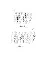
Фиг. 1. Изогнутый переключаемый светофильтр 10, в соответствии с настоящим изобретением, в разобранном виде;FIG. 1. Curved switchable filter 10, in accordance with the present invention, in an unassembled form;
Фиг. 2. Изогнутый переключаемый светофильтр 10’, в соответствии с настоящим изобретением, в разобранном виде;FIG. 2. Curved switchable filter 10 ’, in accordance with the present invention, disassembled;
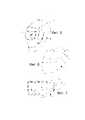
Фиг. 3. Эскизный вид в разрезе изогнутой жидкокристаллической ячейки 34, которая может использоваться в переключаемом светофильтре, в соответствии с настоящим изобретением;FIG. 3. A sketch in section of a curved liquid crystal cell 34, which can be used in a switchable filter, in accordance with the present invention;
Фиг. 4. Структурная схема переключаемого светофильтра 10 (или 10’), расположенного в устройстве 60 автоматически затемняющего светофильтра, в соответствии с настоящим изобретением;FIG. 4. The structural diagram of the switchable filter 10 (or 10 ’) located in the
Фиг. 5. Аксонометрический вид защитного шлема 68 сварщика, в соответствии с настоящим изобретением;FIG. 5. Axonometric view of the protective helmet 68 of the welder, in accordance with the present invention;
Фиг. 6. Аксонометрический вид защитной маски 72, в соответствии с настоящим изобретением;FIG. 6. Axonometric view of the protective mask 72, in accordance with the present invention;
Фиг. 7. Аксонометрический вид защитных очков 76, в соответствии с настоящим изобретением.FIG. 7. Axonometric view of goggles 76, in accordance with the present invention.
Подробное описание изобретенияDETAILED DESCRIPTION OF THE INVENTION
В соответствии с настоящим изобретением, гибкие стеклянные слои определяют замкнутую область, в которой молекулы жидких кристаллов могут свободно вращаться под воздействием электрического поля и создавать эффект фильтрации света. Использование при изготовлении переключаемого светофильтра гибких стеклянных слоев дает возможность соединить компоненты переключаемого светофильтра при помощи ламинирования и придать им изогнутую форму. Такая конструкция обеспечивает более широкое поле зрения при том же (или даже меньшем) весе.In accordance with the present invention, flexible glass layers define a closed region in which liquid crystal molecules can freely rotate under the influence of an electric field and create the effect of filtering light. The use of flexible glass layers in the manufacture of the switchable filter makes it possible to connect the components of the switchable filter with lamination and give them a curved shape. This design provides a wider field of view with the same (or even less) weight.
На фиг. 1 показан изогнутый переключаемый светофильтр 10, в котором внешний компонент светофильтра 10 представляет собой полосовой фильтр 12, который служит для ослабления инфракрасных (ИК) и ультрафиолетовых (УФ) компонентов спектра падающего света высокой интенсивности. Полосовой фильтр 12 может быть интерференционным светофильтром, который отражает ИК излучение и поглощает УФ-А, -В и –С компоненты спектра падающего света. Полосовой фильтр 12 также может представлять собой сочетание отдельных ИК и УФ отражающих и/или поглощающих светофильтров. Изогнутый переключаемый светофильтр 10 также включает первый поляризационный фильтр 14, первую оптически вращающую жидкокристаллическую ячейку 16 и второй поляризационный фильтр 18. Поляризационные фильтры 14 и 18 имеют, в сущности, ортогональные направления поляризации, при этом направление поляризации первого поляризационного фильтра 14 повернуто примерно на 90о относительно направления поляризации второго поляризационного фильтра 18, но расположено в параллельной плоскости. Первая оптически вращающая жидкокристаллическая ячейка 16 может представлять собой жидкокристаллическую ячейку на основе скрученного нематика, расположенную между первым и вторым ортогональными поляризационными фильтрами 14 и 18. Параллельно этим компонентам, между парой поляризационных фильтров 18 и 22, расположена вторая жидкокристаллическая ячейка 20. Поляризационные фильтры 18 и 22 имеют, в сущности, параллельные направления поляризации. Параллельность их направлений поляризации приводит к тому, что ячейка оказывается затемненной, когда к ней не приложено напряжение и прозрачной, когда напряжение к ней приложено. Исходное затемненное состояние ячейки выполняет защитную функцию и предупреждает пользователя о том, что изделие находится в состоянии «выключено». Каждая из жидкокристаллических ячеек 16 и 20 оснащена соединителями 24 и 26, соответственно, при помощи которых к этим ячейкам могут быть подведены управляющие напряжения. Подведение напряжения к соединителям 24 создает электрическое поле между гибкими стеклянными слоями жидкокристаллической ячейки 16. Под воздействием электрического поля, нематические молекулы жидких кристаллов ориентируются перпендикулярно ограничивающим поверхностям, которые покрывают широкие стенки ячейки. Такая перпендикулярная ориентация в возбужденном состоянии ячейки, в отличие от параллельной ориентации, обеспечивает затемненное состояние ячейки. Таким образом, когда к жидкокристаллической ячейке 16 приложено управляющее напряжение, достигается эффект фильтрации. Жидкокристаллическая ячейка управляет поляризацией света и свет поглощается поляризатором. Величиной поворота нематических молекул можно управлять изменяя величину управляющего напряжения, таким образом, можно управлять соответствующим эффектом фильтрации. В результате, жидкокристаллическая ячейка 16 находится в прозрачном состоянии при отсутствии приложенного к ней напряжения, и в затемненном состоянии при наличии приложенного к ней напряжения. Для различных конструкций ячейки уровни напряжений могут быть различными, в зависимости от использованных материалов жидких кристаллов, геометрии зазора ячейки и т.д. На практике, прозрачное состояние соответствует защитным очкам сварщика со степенью затемнения от 2 до 4, а затемненное состояние, которое может выбирать пользователь, соответствует защитным очкам сварщика со степенью затемнения от 7 до 14. Степень затемнения защитных очков сварщика определяется стандартами по защите глаз ANSI 287.1:2010 и 169:2001 – см. также EN 379:2003.In FIG. 1 shows a curved switchable filter 10, in which the external component of the filter 10 is a band-
На фиг. 2. показан изогнутый автоматически затемняющий светофильтр 10’, в разобранном виде, содержащий жидкокристаллические ячейки 16, 20 и 28. Первая жидкокристаллическая ячейка 16 расположена между первым и вторым поляризационными фильтрами 14 и 18, вторая жидкокристаллическая ячейка 20 расположена между первым и третьим поляризационными фильтрами 18 и 22, а третья жидкокристаллическая ячейка 28 расположена между поляризационными фильтрами 30 и 14. Две жидкокристаллические ячейки 16 и 28 могут быть, в сущности, идентичными, но они, в целом, повернуты примерно на 180° по отношению друг к другу, это уменьшает изменение оптических характеристик в зависимости от угла зрения. Подведение напряжения к соединителям 24 и 32 создает между прозрачными электропроводящими электродами электрическое поле. Под воздействием электрического поля, нематические молекулы жидких кристаллов ориентируются перпендикулярно ограничивающим объем с молекулами поверхностям, что приводит к тому, что ячейки ограничивают прохождение света. Направления ориентации жидкокристаллических ячеек 16 и 28 являются, в сущности, параллельными и расположены асимметрически по отношению друг к другу. Преимуществом расположения двух, в сущности, идентичных жидкокристаллических ячеек совместно, таким образом, что направления ориентации молекул обращены друг к другу и, в сущности, перпендикулярны, является то, что это позволяет компенсировать зависимость эффекта фильтрации от угла зрения. Уменьшение изменений степени затемнения (улучшение однородности) в затемненном состоянии может быть достигнуто благодаря использованию поляризаторов со смещением, т.е. поляризаторов со смещением примерно от 1 до 20 градусов – см. Патент США № 7884888, авторы Magnusson и др. Поляризаторы со смещением могут исключить неравномерность затемнения в поле зрения, вызванную изменениями геометрии зазора ячейки, нежелательным двойным лучепреломлением в слоях адгезива конструкции и различными углами зрения.In FIG. 2. shows a bent auto-dimming filter 10 ', in disassembled form, containing
На фиг. 3. показана жидкокристаллическая ячейка 34, такая, как первая, вторая и третья ячейки 16, 20 и 28. Слоистая конструкция содержит два оптически прозрачных гибких стеклянных слоя 40 и 42. При реализации настоящего изобретения могут быть использованы различные стеклянные слои. Толщина каждого из слоев может быть примерно от 10 мкм до 200 мкм, более типично, примерно от 30 мкм до 150 мкм, и еще более типично, примерно от 75 мкм до 125 мкм. Гибкие стеклянные слои 40 и 42 могут поставляться в виде листов или рулонов. Изогнутые слои 40, 42, обычно имеют радиус кривизны менее бесконечности, в типовом случае – примерно от 5 до 30 см, более типично, примерно от 7 до 20 см. Кривизна может иметь непостоянный радиус, например, она может иметь параболическую форму, форму линии провисания, эпициклоидальную или произвольную форму. На внутренних поверхностях оптически прозрачных гибких стеклянных слоев 40 и 42 расположены слои 44 и 46 прозрачных электропроводящих электродов, соответственно, (например, слои оксида индия и олова). При подведении к электродам 44 и 46 напряжения, в слое 48 жидких кристаллов создается электрическое поле, что приводит к сдвигу ориентации молекул жидких кристаллов. Рядом с электродами 44 и 46 расположены ориентирующие слои 50 и 52, соответственно, представляющие собой, например, слои из полиимида, подвергнутые механической обработке, такой как расчёсывание или натирание с определенными направлениями ориентации. Ориентирующие слои 50 и 52 разнесены друг от друга при помощи распорок 54 одинакового размера, расположенных внутри ячеек. Торцы ячейки могут быть герметизированы при помощи контурного адгезива 56, такого как Norland 68, поставляемый фирмой Norland Products, Cranbury, NJ. Перед окончательной герметизацией ячейки, в зазор 48 между слоями 50 и 52 закачивают нематические молекулы 58. Ориентирующие слои 50 и 52 заставляют нематические молекулы 58 жидких кристаллов занимать определенные угловые положения у поверхностей, таким образом, что молекулы повернуты в пределах их соответствующего угла закручивания между этими поверхностями. Величина поворота нематических жидких кристаллов 58 либо обеспечивает прохождение света сквозь ячейку, либо блокирует прохождение света. Могут быть использованы жидкие кристаллы нематического типа с Δn (разностью между показателями преломления для обыкновенного и необыкновенного лучей света) примерно от 08 до 14, помещенные между двумя оптически прозрачными гибкими стеклянными слоями 40 и 42. Зазор между слоями 50 и 52 обычно составляет примерно 3-5 мкм. Используемые в соответствии с настоящим изобретением оптически прозрачные гибкие стеклянные слои 40 и 42, обычно обеспечивают, в сущности, равномерную оптическую прозрачность, обычно более 80%, в диапазоне длин волн от 380 нм до 750 нм. Для того, чтобы иметь указанную выше толщину, стеклянный слой может быть изготовлен способом переливания через край с вытяжкой вниз. Состав стеклянного слоя может представлять собой различные составы силикатного стекла и пр., такие как кварцевое стекло и боросиликатное стекло. Безщелочное стекло может включать стекло, которое, в сущности, не содержит щелочной компонент, в частности, стекло, содержащее 1000 частей на миллион (ppm) или менее (предпочтительно 500 ppm или менее, и, более предпочтительно 300 ppm или менее) оксида щелочного металла. Рядом со стеклянным слоем может быть расположен защитный слой. При намотке стеклянного слоя, защитный слой предотвращает образование трещин, которые возникают из-за соприкосновения одной части стеклянного слоя с другой. Защитный слой поглощает внешнее давление, прикладываемое к рулону стекла. Толщина защитного листа может быть в пределах от 10 мкм до 2000 мкм. Защитный лист может представлять собой иономерную пленку, полиэтиленовую пленку, полипропиленовую пленку, пленку из поливинилхлорида, пленку из поливинилиденхлорида, поливинилспиртовую пленку, полиэфирную плёнку, пленку из поликарбоната, пленку из полистирола, пленку из полиакрилонитрила, пленку из сополимера этилена и винилацетата, пленку из сополимера этилен-винилового спирта, пленку из сополимера этилен-метакриловой кислоты, пленку из нейлона (пленку из полиамида), пленку из полиимида, целлофановую плёнку или иные буферные материалы, изготовленные из смол. Защитному листу может быть обеспечена электропроводность, за счет добавления в защитный лист компонента, предназначенного для придания электропроводности, такого как полиэтиленгликоль. В том случае, когда защитный лист формируется прокладыванием бумаги, электропроводность может быть обеспечена за счет добавления электропроводного волокна. Кроме того, электропроводность также может быть обеспечена за счет нанесения, при помощи ламинирования, на поверхность защитного листа электропроводного слоя, такого как пленка оксида индия и олова. См. патент США № 8241751, автор Tomamoto и др., см. также патент США № 7735338, автор Mueller и др., заявку на патент США № 2011/0059296. Примером коммерчески доступного гибкого стекла является стекло марки Schott D263T.In FIG. 3. A liquid crystal cell 34, such as the first, second, and
Жидкокристаллические ячейки 16, 20 и 28 могут представлять собой жидкокристаллические ячейки со скрученным нематиком, которые обеспечивают «отказоустойчивое» промежуточное переходное состояние в случае выхода из строя электронного блока. Автоматически затемняющий светофильтр, имеющий жидкокристаллические ячейки со слабой круткой, описывается в патенте США № 6097451, автор Palmer и др.; см. также патент США № 5825441, автор Hornell и др. Жидкокристаллическая ячейка со скрученным нематиком может иметь угол скручивания менее 100 градусов, обычно от нуля или 1 до 99 градусов. Жидкокристаллическая ячейка также может иметь угол скручивания, соответствующий слабой крутке, в пределах от 1 до 85 градусов. В частности, угол скручивания жидкокристаллической ячейки со слабой круткой может быть от 30 до 70 градусов. «Отказоустойчивая» жидкокристаллическая ячейка во многом сходна по конструкции с жидкокристаллической ячейкой со слабой круткой, но имеет иной принцип действия, поскольку она размещена между параллельными поляризаторами, а не перекрещивающимися или ортогональными поляризаторами. Жидкокристаллическая ячейка 20 находится в затемненном состоянии (почти непрозрачном состоянии, в котором бОльшая часть падающего света задерживается) когда к соединителям 26 не приложено напряжение. Жидкокристаллическая ячейка 20 может стать оптически прозрачной при приложении к ней определенного напряжения.The
На фиг. 4 приведена структурная схема автоматически затемняющего светофильтра 60 (АЗС). Автоматически затемняющий светофильтр 60 включает изогнутый переключаемый светофильтр 10 (или 10’), который имеет поляризаторы со смещением, аналогичные описанным при рассмотрении фиг. 1 и фиг. 2. Переключаемый светофильтр 10 установлен в защитном шлеме 62, который пользователь надевает во время процесса сварки или в иной ситуации, в которой необходима такая защита, которую обеспечивает переключаемый светофильтр 10. АЗС 60 также включает датчик 64, предназначенный для обнаружения падающего на переднюю поверхность светофильтра 10 света, исходящего, например, от сварочной дуги. Датчик обнаруживает падающий свет и посылает сигнал, который вызывает вращение молекул в слое жидких кристаллов. Датчик 64 может быть оснащен поляризующим элементом, который препятствует тому, чтобы свет падающий не по нормали мог активировать датчик. Такое устройство предотвращает попадание на датчик света от других сварочных горелок и источников – см. патент США № 6934967, автор Migashita и др. Схема 66 управления принимает от датчика 64 сигналы, соответствующие наличию или отсутствию падающего света, и подводит к светофильтру 10 соответствующие управляющие напряжения, управляя таким образом степенью затемнения светофильтра 10. Например, если датчик 64 обнаруживает наличие сварочной дуги или иного источника падающего света, то схема 66 управления может подвести управляющие напряжения к жидкокристаллическим ячейкам 16 и 20 (см. фиг. 1 и фиг. 2), и снять напряжение с жидкокристаллической ячейки 28 на эффекте "гость-хозяин" (см. фиг. 2). Это приводит к тому, что светофильтр 60 переходит в затемненное состояние и защищает пользователя от ослепления падающим светом. В отсутствие сварочной дуги или иного источника падающего света, схема 66 управления может уменьшить или отключить подведенное к жидкокристаллическим ячейкам 16 и 20 напряжение, таким образом, делая светофильтр более прозрачным для прохождения света. Увеличение пропускания света, позволяет сварщику, например, выполнять сварочные операции и, также, выполнять работы за пределами зоны сварки, не снимая защитный шлем или маску. Кроме того, описанная здесь конструкция светофильтра улучшает однородность светофильтра в затемненном состоянии в широком диапазоне углов зрения со стороны пользователя. Переключаемый светофильтр 10, датчик 64 и схема 66 управления обычно установлены на защитном шлеме как единый узел, обычно, как сменный узел, который установлен в держателе, прямо перед глазами пользователя, когда пользователь надевает шлем. Узел может иметь форму прямоугольной рамки (или рамки иной формы) или корпуса, который удерживает светофильтр, датчик и схему. Примеры реализации держателя для шлема приведены, например, в патентах США 6185739, 5533206, 5191468, 5140707, 4875235 и 4853973. Шлемы сварщика могут также предусматривать подачу чистого воздуха во внутреннюю область и, поэтому, могут включать уплотнительное кольцо, предназначенное для отделения зоны дыхания от окружающего воздуха. Пример реализации такого уплотнительного кольца приведен в патенте США № 7197774, автор Curran и др.; см. также патенты США на промышленный образец D517 744, D517 745, D518 923, D523 728 и D532 163; и заявки на патент США № 2006-0101552 и № 2006-0107431.In FIG. 4 shows a block diagram of an automatically dimming filter 60 (gas station). The auto-dimming
На фиг. 5 приведен аксонометрический вид защитного шлема 68 сварщика, который имеет основу 70 шлема, которое содержит устройство 60 автоматически затемняющего светофильтра, установленное в отверстии основы 70 шлема. Основа 70 шлема может включать венцовый элемент, который соприкасается с головой пользователя, когда устройство 68 надето. Пример подходящего венцового элемента описан в патенте США № 7865968, автор Lilenthal и др.; см. также заявку на патент США 2010/229286 А1, автор Ahlgren и др. Устройство 60 автоматически затемняющего светофильтра включает изогнутый автоматически затемняющий светофильтр 10, который расположен таким образом, чтобы он задерживал электромагнитное излучение (например, видимый свет, ультрафиолетовое излучение, инфракрасное излучение и т.д.). Автоматически затемняющий светофильтр 60 может быть расположен в основе 70 шлема таким образом, чтобы он находился прямо перед глазами пользователя, когда пользователь надевает шлем.In FIG. 5 is a perspective view of a welder's protective helmet 68, which has a helmet base 70 that includes an automatic
Автоматически затемняющий светофильтр 60 может включать электронный блок 66 управления (см. фиг. 5), предназначенный для приема и формирования различных сигналов, направляемых на изогнутый автоматический светофильтр 10 для сварщика и, в частности, на жидкокристаллические ячейки 16, 20 и 28, через соединители 24, 26 и 32, соответственно (см. фиг. 2) – см., например, заявку на патент США № US2010-265421 (автор - Sundell). Электронный блок управления может также включать детектор входных воздействий, который может обнаруживать, по меньшей мере, входное воздействие от присутствующего светового излучения с высокой интенсивностью. Детектор может быть физически расположен вблизи от некоторых или от всех других компонентов (электронной схемы и т.д.) устройства 60 автоматически затемняющего светофильтра или может быть физически расположен на некотором удалении от некоторых или от всех этих компонентов. Детектор может быть выполнен с использованием различных устройств фотодетекторов и технологий. В альтернативном воплощении, входное воздействие, которое означает присутствие светового излучения с высокой интенсивностью, может быть сформировано электронным блоком управления под воздействием сигнала активации, сформированного, например, сварочным аппаратом или сварочной горелкой – см. патент WO2007/047264, автор Garbergs и др.The auto-dimming
На фиг. 6 показан один из примеров воплощения настоящего изобретения, в котором изогнутый переключаемый светофильтр 10, в соответствии с настоящим изобретением, установлен в подходящем устройстве 72 защиты лица. Переключаемый светофильтр 10 может быть установлен в устройстве защиты лица таким образом, что он имеет возможность поворота вокруг точки 73 поворота. В альтернативном воплощении настоящего изобретения, изогнутый автоматический светофильтр 10 для сварщика может быть установлен в устройстве автоматически затемняющего светофильтра расположенном в защитных очках 76, как показано на фиг. 7.In FIG. 6 shows one exemplary embodiment of the present invention, in which a curved switchable filter 10, in accordance with the present invention, is installed in a suitable face protection device 72. The switchable filter 10 can be installed in the face protection device so that it has the ability to rotate around the point 73 of rotation. In an alternative embodiment of the present invention, the curved automatic filter 10 for the welder may be installed in an automatically dimming filter device located in the safety glasses 76, as shown in FIG. 7.
Переключаемые светофильтры, в соответствии с настоящим изобретением, могут быть изогнутыми вокруг одной, двух или трех осей. Обычно, переключаемый светофильтр, используемый в сварочном шлеме (см. фиг. 5) может быть изогнутым вокруг одной или двух осей. Физические свойства гибких стеклянных слоев позволяют изготавливать изогнутые переключаемые светофильтры, которые имеют радиус кривизны примерно от 5 до 20 см, и площадь поля зрения, примерно от 10 до 600 см2, более типично – от 30 см2до 250 см2. Известные светофильтры для сварки, обычно, имеют площадь поля зрения, примерно от 50 до 100 см2. В настоящем изобретении предлагаются переключаемые светофильтры, имеющие площадь поля зрения, по меньшей мере, от 100 см2до 125 см2.Switchable filters in accordance with the present invention may be curved around one, two or three axes. Typically, the switchable filter used in the welding helmet (see FIG. 5) may be bent around one or two axes. The physical properties of the flexible glass layers allow the manufacture of curved switchable filters that have a radius of curvature of about 5 to 20 cm, and a field of view of about 10 to 600 cm2 , more typically from 30 cm2 to 250 cm2 . Known filters for welding typically have a field of view of about 50 to 100 cm2 . The present invention provides switchable filters having a field of view of at least 100 cm2 to 125 cm2 .
Устройства автоматически затемняющего светофильтра, в соответствии с настоящим изобретением, могут использоваться при выполнении различных промышленных операций, например, сварки (например, дуговой сварки, газовой сварки, ацетиленовой сварки), резки (например, лазерной резки, ацетиленовой резки), пайки тугоплавким припоем, пайки и т.д. Они также могут использоваться при выполнении различных медицинских процедур, при которых может возникать световое излучение с высокой интенсивностью (например, лазерная хирургия, удаление волос, удаление татуировок, отверждение связующих для зубопротезных материалов при помощи оптического излучения) и других. Одно или более устройств автоматически затемняющего светофильтра могут быть предложены для любых иных подходящих устройств или изделий и для иных применений. Например, устройство автоматически затемняющего светофильтра может поставляться как часть защитных очков, а не шлема, закрывающего все лицо. В альтернативном воплощении настоящего изобретения, устройство автоматически затемняющего светофильтра может быть встроено в портативное устройство или в окошко или отверстие, которое обеспечивает возможность проведения осмотра комнаты, корпуса, машинного отделения и т.д., в которых может присутствовать световое излучение с высокой интенсивностью.Automatic dimming filter devices in accordance with the present invention can be used in various industrial operations, for example, welding (e.g., arc welding, gas welding, acetylene welding), cutting (e.g. laser cutting, acetylene cutting), reflow soldering, soldering, etc. They can also be used in various medical procedures in which light radiation with high intensity can occur (for example, laser surgery, hair removal, tattoo removal, curing binders for denture materials using optical radiation) and others. One or more automatic dimming filter devices may be offered for any other suitable devices or products and for other applications. For example, an auto-dimming filter device may be supplied as part of safety goggles, rather than a helmet covering the entire face. In an alternative embodiment of the present invention, the auto-dimming filter device can be integrated in a portable device or in a window or hole that allows inspection of a room, housing, engine room, etc., in which high-intensity light may be present.
ПРИМЕРEXAMPLE
Узел жидкокристаллической ячейкиLCD cell assembly
Изогнутую жидкокристаллическую ячейку для автоматического светофильтра для сварщика изготавливали следующим образом.A curved liquid crystal cell for an automatic filter for a welder was made as follows.
Исходный гибкий стеклянный слой представлял собой стекло марки D263T толщиной 0,1 мм, поставляемое фирмой Schott Glass of Schott Glas Export, GmbH, расположенной - Rheinallee 145, 55120 Mainz, Germany. На стекло при помощи распыления был осажден оксид индия и олова. Электропроводность покрытия из оксида индия и олова составляла примерно 100 Ом/квадрат. Стекло с покрытием из оксида индия и олова покрывали тонким слоем полиимидного полимера. Стекло покрывали коммерчески доступным полиимидным ориентирующим материалом при помощи центрифугирования. Толщина покрытия после просушки была в пределах от 80 нм до 200 нм. Тонкий полиимидный слой ориентировали при помощи прочёсывания вращающимся войлочным материалом. Этот образец, состоящий из прочесанного полиимида и стекла/оксида индия и олова, разрезали на куски для изготовления верхней и нижней частей жидкокристаллической ячейки. Для получения нужной ориентации, первый кусок (верхний) поворачивали на 90о по отношению ко второму (нижнему) куску стекла.The original flexible glass layer was 0.1 mm thick D263T grade glass supplied by Schott Glass of Schott Glas Export, GmbH, located Rheinallee 145, 55120 Mainz, Germany. Indium and tin oxide were deposited onto the glass by spraying. The conductivity of the indium and tin oxide coating was about 100 ohms / square. Glass coated with indium oxide and tin was coated with a thin layer of polyimide polymer. The glass was coated with a commercially available polyimide orienting material by centrifugation. The coating thickness after drying was in the range from 80 nm to 200 nm. A thin polyimide layer was oriented by combing with a rotating felt material. This sample, consisting of carded polyimide and glass / indium and tin oxide, was cut into pieces to make the upper and lower parts of the liquid crystal cell. To obtain the desired orientation, the first piece (upper) was rotated 90° with respect to the second (lower) piece of glass.
Изогнутую жидкокристаллическую ячейку формовали, используя в качестве оправки металлический цилиндр, имевший радиус, примерно 90 мм. Нижнюю часть жидкокристаллической ячейки, представлявшую собой стекло с покрытием из оксида индия и олова, покрытое прочесанным полиимидом, приматывали к металлическому цилиндру при помощи ленты типа 3M Magic Tape™. Контурный адгезив (оптический адгезив, отверждаемый УФ-излучением, типа Norland 68) наносили на нижнюю часть при помощи шприца с иголкой. В состав скрученных нематических жидких кристаллов добавляли 1% по весу керамических разделительных шариков диаметром 4 мкм. Смесь жидких кристаллов и разделительных шариков размещали на нижней части ячейки при помощи пипетки. Верхнюю часть ячейки присоединяли к нижней части вдоль передней кромки при помощи ленты типа 3M Removable Tape™. Затем, при помощи полиэфирной пленки, один конец которой был прикреплен к металлическому цилиндру, верхнюю часть ячейки, изгибая, приматывали к нижней части. При помощи резинового валика верхнюю часть прижимали к нижней части. Полиэфирная пленка удерживалась под натяжением, для того, чтобы компоненты ячейки находились в плотном контакте друг с другом. Затем контурный адгезив, отверждаемый УФ-излучением, отверждали воздействием источника УФ-излучения в течение 5 минут. После этого, готовую ячейку снимали с цилиндра, удаляя полиэфирную пленку и куски ленты. К нижней и верхней частям при помощи адгезива, отверждаемого давлением, присоединяли поляризующие пленки. Поляризующие пленки располагались ортогонально по отношению друг к другу и в соответствии с ориентацией, приданной полиимидному слою. К слою оксида индия и олова на верхней части присоединяли медную ленту с электропроводным адгезивом, а другую медную ленту с электропроводным адгезивом присоединяли к слою оксида индия и олова на нижней части. Посредством медных лент, к ячейке подводили разность потенциалов в 10 В. При подведении напряжения, ячейка переключалась из светопропускающего состояния в затемненное состояние. Размеры готовой ячейки составляли, примерно, 75 мм в ширину и 75 мм в длину (5625 мм2; 56,25 см2), при этом ее кривизна была немного меньше, чем у исходного цилиндра с радиусом в 100 мм.A curved liquid crystal cell was formed using a metal cylinder having a radius of about 90 mm as a mandrel. The lower part of the liquid crystal cell, which was glass coated with indium oxide and tin, coated with carved polyimide, was wound onto a metal cylinder using 3M Magic Tape ™ tape. A contour adhesive (UV-curable optical adhesive, such as Norland 68) was applied to the bottom using a syringe with a needle. The composition of twisted nematic liquid crystals was added 1% by weight of ceramic dividing balls with a diameter of 4 μm. A mixture of liquid crystals and separation beads was placed on the bottom of the cell using a pipette. The top of the cell was attached to the bottom along the leading edge using 3M Removable Tape ™ tape. Then, using a polyester film, one end of which was attached to a metal cylinder, the upper part of the cell, curving, was wound to the lower part. Using a rubber roller, the upper part was pressed to the lower part. The polyester film was held under tension so that the cell components were in close contact with each other. Then, the UV curable adhesive was cured by exposure to a UV source for 5 minutes. After that, the finished cell was removed from the cylinder, removing the polyester film and pieces of tape. Polarizing films were attached to the lower and upper parts using pressure curing adhesive. The polarizing films were arranged orthogonally with respect to each other and in accordance with the orientation given to the polyimide layer. A copper tape with an electrically conductive adhesive was attached to the indium and tin oxide layer on the upper part, and another copper and tape with an electrically conductive adhesive was attached to the bottom layer of indium and tin oxide. Using copper tapes, a potential difference of 10 V was applied to the cell. When voltage was applied, the cell switched from a light transmitting state to a darkened state. The dimensions of the finished cell were approximately 75 mm wide and 75 mm long (5625 mm2 ; 56.25 cm2 ), while its curvature was slightly less than that of the original cylinder with a radius of 100 mm.
Настоящее изобретение допускает внесение различных модификаций и изменений, без отхода от идеи и масштабов настоящего изобретения. Соответственно, настоящее изобретение не ограничивается описанными выше воплощениями, а масштаб изобретения ограничен прилагаемой формулой изобретения и ее эквивалентами.The present invention is capable of making various modifications and changes without departing from the spirit and scope of the present invention. Accordingly, the present invention is not limited to the embodiments described above, and the scope of the invention is limited by the appended claims and their equivalents.
Настоящее изобретение может быть воплощено при отсутствии любого из элементов, не описываемого здесь специально.The present invention may be embodied in the absence of any of the elements not specifically described herein.
Все патенты и заявки на получение патентов, на которые приведены ссылки выше, в том числе и приведенные в разделе «Уровень техники», включены настоящее описание для ссылки целиком. В том случае, если имеется противоречие или расхождение между настоящим описанием и документом, на который дается ссылка, следует руководствоваться настоящим описанием.All patents and patent applications referenced above, including those listed in the section "prior art", the present description is incorporated by reference in its entirety. In the event that there is a conflict or discrepancy between the present description and the referenced document, this description should be guided.
Claims (20)
Translated fromRussianApplications Claiming Priority (2)
| Application Number | Priority Date | Filing Date | Title |
|---|---|---|---|
| US13/713,331 | 2012-12-13 | ||
| US13/713,331US20140168546A1 (en) | 2012-12-13 | 2012-12-13 | Curved Automatic-Darkening Filter |
Related Parent Applications (1)
| Application Number | Title | Priority Date | Filing Date |
|---|---|---|---|
| RU2017106286ADivisionRU2678214C2 (en) | 2012-12-13 | 2013-11-25 | Curved automatically dimming light filter |
Publications (1)
| Publication Number | Publication Date |
|---|---|
| RU2719306C1true RU2719306C1 (en) | 2020-04-17 |
Family
ID=50930477
Family Applications (3)
| Application Number | Title | Priority Date | Filing Date |
|---|---|---|---|
| RU2017106286ARU2678214C2 (en) | 2012-12-13 | 2013-11-25 | Curved automatically dimming light filter |
| RU2015120706ARU2015120706A (en) | 2012-12-13 | 2013-11-25 | Curved auto-dimming filter |
| RU2019100551ARU2719306C1 (en) | 2012-12-13 | 2019-01-14 | Bent automatically darkening filter |
Family Applications Before (2)
| Application Number | Title | Priority Date | Filing Date |
|---|---|---|---|
| RU2017106286ARU2678214C2 (en) | 2012-12-13 | 2013-11-25 | Curved automatically dimming light filter |
| RU2015120706ARU2015120706A (en) | 2012-12-13 | 2013-11-25 | Curved auto-dimming filter |
Country Status (10)
| Country | Link |
|---|---|
| US (3) | US20140168546A1 (en) |
| EP (3) | EP2932315A4 (en) |
| KR (1) | KR102211210B1 (en) |
| CN (2) | CN106773202B (en) |
| AU (2) | AU2013360166B2 (en) |
| DE (1) | DE202013012794U1 (en) |
| RU (3) | RU2678214C2 (en) |
| SI (1) | SI3185068T1 (en) |
| TW (2) | TW201430455A (en) |
| WO (1) | WO2014092989A1 (en) |
Cited By (1)
| Publication number | Priority date | Publication date | Assignee | Title |
|---|---|---|---|---|
| EP3988238A1 (en) | 2020-10-24 | 2022-04-27 | Alexey Malov | Welding shield with artificial intelligence-controlled display |
Families Citing this family (58)
| Publication number | Priority date | Publication date | Assignee | Title |
|---|---|---|---|---|
| US20140168546A1 (en) | 2012-12-13 | 2014-06-19 | 3M Innovative Properties Company | Curved Automatic-Darkening Filter |
| EP2839817B1 (en)* | 2013-08-05 | 2019-07-31 | Optrel Holding AG | Face protector |
| US9999546B2 (en) | 2014-06-16 | 2018-06-19 | Illinois Tool Works Inc. | Protective headwear with airflow |
| CN105455947A (en)* | 2014-09-09 | 2016-04-06 | 泰克曼(南京)电子有限公司 | Automatic light-changing welding mask with arc-shaped liquid crystal display panel |
| CN104299525A (en) | 2014-11-03 | 2015-01-21 | 京东方科技集团股份有限公司 | Curved surface display panel, device and manufacturing method thereof |
| US9581543B2 (en)* | 2014-11-10 | 2017-02-28 | Ci Systems (Israel) Ltd. | Infrared detection and imaging device with no moving parts |
| JP6710690B2 (en)* | 2015-01-19 | 2020-06-17 | メルク パテント ゲゼルシャフト ミット ベシュレンクテル ハフツングMerck Patent Gesellschaft mit beschraenkter Haftung | Devices for controlling the transmission of light |
| JP7073249B2 (en)* | 2015-07-16 | 2022-05-23 | メルク パテント ゲゼルシャフト ミット ベシュレンクテル ハフツング | A device for controlling the transmission of light |
| KR102010760B1 (en) | 2015-10-26 | 2019-08-14 | 주식회사 엘지화학 | Optical device |
| US20190025624A1 (en)* | 2015-12-31 | 2019-01-24 | Kimberly-Clark Worldwide, Inc. | Two mode electro-optic filter |
| KR20180121568A (en) | 2016-03-09 | 2018-11-07 | 코닝 인코포레이티드 | Cold Forming of Composite Curved Glass Products |
| US10821026B2 (en)* | 2016-04-27 | 2020-11-03 | 3M Innovative Properties Company | Welding protector with magnifying cover |
| EP3241533A1 (en)* | 2016-05-04 | 2017-11-08 | 3M Innovative Properties Company | A curved eye protection shield for welding protection |
| CN109152661B (en)* | 2016-05-12 | 2020-02-04 | 3M创新有限公司 | Protective helmet comprising a curved switchable shutter and comprising a plurality of antireflection layers |
| JP7051720B2 (en) | 2016-06-28 | 2022-04-11 | コーニング インコーポレイテッド | Laminating thin tempered glass on curved molded plastic surfaces for decorative and display cover applications |
| KR102597034B1 (en)* | 2016-07-05 | 2023-11-01 | 코닝 인코포레이티드 | Cold-formed glass article and assembly process thereof |
| CN106214333A (en)* | 2016-09-07 | 2016-12-14 | 芜湖德鑫汽车部件有限公司 | Ear suspension type welding mask |
| CN107966834B (en)* | 2016-10-20 | 2020-08-28 | 泰克曼(南京)电子有限公司 | Auto-darkening filter for high shade numbers |
| WO2018081068A1 (en) | 2016-10-25 | 2018-05-03 | Corning Incorporated | Cold-form glass lamination to a display |
| CN108472776B (en)* | 2016-11-04 | 2019-11-22 | 山崎马扎克公司 | Composite processing device and composite processing method |
| US20190258111A1 (en) | 2016-11-08 | 2019-08-22 | 3M Innovative Properties Company | Flat Automatic Darkening Filter And Welding Protector |
| EP3320880A1 (en)* | 2016-11-11 | 2018-05-16 | 3M Innovative Properties Company | An automatic darkening filter assembly for a welding protector and a welding protector |
| EP3329887B1 (en)* | 2016-11-30 | 2020-04-22 | Optrel Holding AG | Optical glare shield filter |
| US10712850B2 (en) | 2017-01-03 | 2020-07-14 | Corning Incorporated | Vehicle interior systems having a curved cover glass and a display or touch panel and methods for forming the same |
| US11016590B2 (en) | 2017-01-03 | 2021-05-25 | Corning Incorporated | Vehicle interior systems having a curved cover glass and display or touch panel and methods for forming the same |
| CN113157125A (en) | 2017-01-03 | 2021-07-23 | 康宁公司 | Vehicle interior system with curved cover glass and display or touch panel and method of forming same |
| US11812816B2 (en) | 2017-05-11 | 2023-11-14 | Illinois Tool Works Inc. | Protective headwear with airflow |
| JP7357546B2 (en) | 2017-05-15 | 2023-10-06 | コーニング インコーポレイテッド | Contoured glass article and method for making the same |
| CN110740714B (en)* | 2017-06-15 | 2022-04-29 | 3M创新有限公司 | Sight protective headgear with automatic darkening filter including switchable shutter array |
| CN117962601A (en) | 2017-07-18 | 2024-05-03 | 康宁公司 | Cold forming of complex curved glass articles |
| KR102574235B1 (en) | 2017-09-12 | 2023-09-11 | 코닝 인코포레이티드 | Tactile elements for deadfront glass and methods for manufacturing the same |
| US11065960B2 (en) | 2017-09-13 | 2021-07-20 | Corning Incorporated | Curved vehicle displays |
| TWI873668B (en) | 2017-09-13 | 2025-02-21 | 美商康寧公司 | Light guide-based deadfront for display, related methods and vehicle interior systems |
| US10866442B2 (en)* | 2017-09-15 | 2020-12-15 | 3M Innovative Properties Company | Curved, arcuately-bonded liquid crystal cell and method of making |
| TWI888167B (en) | 2017-10-10 | 2025-06-21 | 美商康寧公司 | Vehicle interior systems having a curved cover glass with improved reliability and methods for forming the same |
| GB2568240B (en)* | 2017-11-03 | 2023-01-25 | Flexenable Ltd | Method of producing liquid crystal devices comprising a polariser component between two lc cells |
| US11768369B2 (en) | 2017-11-21 | 2023-09-26 | Corning Incorporated | Aspheric mirror for head-up display system and methods for forming the same |
| TWI789463B (en) | 2017-11-30 | 2023-01-11 | 美商康寧公司 | Vacuum mold apparatus, systems, and methods for forming curved mirrors |
| WO2019108016A1 (en) | 2017-11-30 | 2019-06-06 | Corning Precision Materials Co., Ltd. | Systems and methods for vacuum-forming aspheric mirrors |
| EP3501464B1 (en) | 2017-12-20 | 2022-04-06 | Optrel Holding AG | Protective cartridge for an antiglare device |
| CN111936891B (en) | 2018-03-02 | 2023-03-24 | 康宁公司 | Anti-reflective coating and article and method of forming the same |
| US11718071B2 (en) | 2018-03-13 | 2023-08-08 | Corning Incorporated | Vehicle interior systems having a crack resistant curved cover glass and methods for forming the same |
| CN112672984B (en) | 2018-07-12 | 2023-03-10 | 康宁公司 | Non-electric plate configured for color comparison |
| JP2021531187A (en) | 2018-07-16 | 2021-11-18 | コーニング インコーポレイテッド | Vehicle interior system with cold bent glass substrate and its formation method |
| CN108897147B (en)* | 2018-07-20 | 2020-09-25 | 中国科学院光电技术研究所 | High-efficiency super-surface device based on catenary structure |
| CN211187783U (en)* | 2018-08-15 | 2020-08-07 | 泰克曼(南京)电子有限公司 | Auto-darkening welding masks and welding equipment equipped therewith |
| EP3650835A1 (en)* | 2018-11-12 | 2020-05-13 | Infineon Technologies AG | Stacked optical filter arrangement for a photoacoustic spectrometry device for multi-gas sensing and photoacoustic spectrometry device |
| EP3741333A1 (en) | 2019-05-23 | 2020-11-25 | 3M Innovative Properties Company | Darkening filter comprising a non-uniform pattern of switchable shutters |
| CN110308580B (en)* | 2019-06-26 | 2025-05-13 | 厦门天马微电子有限公司 | Curved liquid crystal display device and method for manufacturing the same |
| EP3767378A1 (en) | 2019-07-19 | 2021-01-20 | 3M Innovative Properties Company | Automatic darkening filter with simplified set-up |
| EP3771695A1 (en) | 2019-07-31 | 2021-02-03 | Corning Incorporated | Method and system for cold-forming glass |
| KR102304918B1 (en)* | 2019-09-20 | 2021-09-27 | 주식회사 오토스윙 | Welding protector with photo functional layer and Pannel control technology |
| US11772361B2 (en) | 2020-04-02 | 2023-10-03 | Corning Incorporated | Curved glass constructions and methods for forming same |
| USD942530S1 (en) | 2020-06-02 | 2022-02-01 | Fabio Arguello, Jr. | Goggles |
| JP6890861B1 (en)* | 2020-10-21 | 2021-06-18 | 株式会社Hakutakaクリエイトコーポレーション | Manufacturing method of sanitary mask with antibacterial member |
| EP4430448A4 (en) | 2021-11-11 | 2025-03-12 | Alphamicron, Inc. | Light protection system and method |
| EP4459337A1 (en) | 2022-05-03 | 2024-11-06 | Marcello Gasparini | Lighting device with reflected and/or refracted light through polarising filters |
| WO2024222947A1 (en)* | 2023-04-27 | 2024-10-31 | Tecmen Electronics Co., Ltd | Auto-darkening filter and protective helmet for laser processing protection |
Citations (3)
| Publication number | Priority date | Publication date | Assignee | Title |
|---|---|---|---|---|
| EP0957852A1 (en)* | 1995-10-26 | 1999-11-24 | Hörnell International AB | A liquid crystal shutter and a light shielding device including such a shutter |
| US20090201137A1 (en)* | 2000-03-02 | 2009-08-13 | Donnelly Corporation | Rearview assembly with display |
| US20110194040A1 (en)* | 2010-02-08 | 2011-08-11 | Du Pont Apollo Limited | Auto light-shading system |
Family Cites Families (89)
| Publication number | Priority date | Publication date | Assignee | Title |
|---|---|---|---|---|
| US517745A (en) | 1894-04-03 | Steam-boiler | ||
| US518923A (en) | 1894-04-24 | John s | ||
| US523728A (en) | 1894-07-31 | Bottle-neck | ||
| US517744A (en) | 1894-04-03 | Island | ||
| US532163A (en) | 1895-01-08 | Conduit tramway | ||
| SE425048B (en) | 1978-04-24 | 1982-08-30 | Ake Hornell | MULTIPLE GLASS, SEPARATE PROTECTIVE GLASS IN A WELDING SCREEN |
| US4385806A (en) | 1978-06-08 | 1983-05-31 | Fergason James L | Liquid crystal display with improved angle of view and response times |
| JPS5995513A (en) | 1982-11-25 | 1984-06-01 | Toray Ind Inc | Liquid-crystal display cell |
| US4853973A (en) | 1988-03-18 | 1989-08-08 | Jackson Products, Inc. | Welding helmet |
| US4875235A (en) | 1988-07-27 | 1989-10-24 | Kuhlman Thomas E | Welder's mask with breath controlled eye shield |
| US5113270A (en) | 1988-10-19 | 1992-05-12 | Fergason James L | Variable density light control apparatus |
| US5015086A (en) | 1989-04-17 | 1991-05-14 | Seiko Epson Corporation | Electronic sunglasses |
| SE467087B (en) | 1989-06-05 | 1992-05-25 | Hoernell Elektrooptik Ab | Welding helmet comes with one kind of quick filter |
| US5140707A (en) | 1990-10-17 | 1992-08-25 | Johnson Gary L | Welder's safety helmet |
| JPH04175725A (en) | 1990-11-09 | 1992-06-23 | Toyota Motor Corp | Manufacturing method of curved liquid crystal cell |
| US5514504A (en)* | 1991-01-31 | 1996-05-07 | Dai Nippon Printing Co., Ltd. | Information recording medium, and information recording a reproducing method |
| US5208688A (en) | 1991-02-08 | 1993-05-04 | Osd Envizion Company | Eye protection device for welding helmets |
| JP2701629B2 (en)* | 1991-11-01 | 1998-01-21 | カシオ計算機株式会社 | Liquid crystal display device and manufacturing method thereof |
| US5184156A (en) | 1991-11-12 | 1993-02-02 | Reliant Laser Corporation | Glasses with color-switchable, multi-layered lenses |
| WO1993013449A1 (en) | 1991-12-26 | 1993-07-08 | Osd Envizion Company | Eye protection device for welding helmets and the like |
| SE502840C2 (en)* | 1993-05-10 | 1996-01-29 | Optrel Ag | visibility Protective |
| SE502868C2 (en) | 1994-04-26 | 1996-02-05 | Hoernell Elektrooptik Ab | Welding quick filter with improved angular properties |
| JPH07301789A (en) | 1994-05-06 | 1995-11-14 | Casio Comput Co Ltd | Liquid crystal display device and manufacturing method thereof |
| US5533206A (en) | 1995-08-23 | 1996-07-09 | Jackson Products, Inc. | Welding helmet with removable electronic quick change cartridge |
| SE508272C2 (en) | 1995-10-26 | 1998-09-21 | Hoernell International Ab | Liquid crystal shutter assembly, and a light shading device comprising such a structure |
| SE509569C2 (en) | 1995-10-26 | 1999-02-08 | Hoernell International Ab | Liquid crystal shutter construction |
| JPH1039281A (en) | 1996-07-19 | 1998-02-13 | Ricoh Co Ltd | Liquid crystal display device |
| JPH10268790A (en)* | 1997-03-24 | 1998-10-09 | Seiko Epson Corp | LIQUID CRYSTAL DISPLAY PANEL HOLDER, LIQUID CRYSTAL DISPLAY USING THE SAME, ELECTRONIC APPARATUS USING THE LIQUID CRYSTAL DISPLAY DEVICE, CURABLE LIQUID CRYSTAL DISPLAY PANEL MANUFACTURING JIG AND METHOD FOR MANUFACTURING CURVED LIQUID CRYSTAL DISPLAY PANEL USING THE SAME |
| AUPO852697A0 (en) | 1997-08-12 | 1997-09-04 | Comweld Group Pty Ltd | Light shielding helmet |
| JP4175725B2 (en) | 1999-03-31 | 2008-11-05 | 三洋電機株式会社 | Thin battery |
| JP2002014359A (en)* | 2000-06-30 | 2002-01-18 | Minolta Co Ltd | Method and device for manufacturing liquid crystal display curved surface panel |
| US6934967B2 (en) | 2000-11-09 | 2005-08-30 | 3M Innovative Properties Company | Welding operation liquid crystal protection mask |
| DE10064977C1 (en) | 2000-12-23 | 2002-10-02 | Schott Glas | Device for the production of thin glass panes |
| US7102602B2 (en) | 2001-09-18 | 2006-09-05 | Alphamicron, Inc. | Doubly curved optical device for eyewear and method for making the same |
| KR100685923B1 (en)* | 2002-03-25 | 2007-02-23 | 엘지.필립스 엘시디 주식회사 | Bonding device and manufacturing method of liquid crystal display device using the same |
| US7395447B2 (en)* | 2002-09-16 | 2008-07-01 | Silicon Labs Cp, Inc. | Precision oscillator for an asynchronous transmission system |
| CH696021A5 (en) | 2002-09-23 | 2006-11-30 | Optrel Ag | Anti-glare device. |
| WO2004049050A1 (en)* | 2002-11-22 | 2004-06-10 | Koninklijke Philips Electronics N.V. | Method of manufacturing a curved display |
| AU2003293483A1 (en) | 2002-12-11 | 2004-06-30 | Optiva, Inc. | Liquid crystal shutter |
| US7008055B2 (en) | 2003-03-19 | 2006-03-07 | Gpt Glendale, Inc. | Eye protection methods and apparatus |
| CN1753160A (en)* | 2004-09-21 | 2006-03-29 | 中华映管股份有限公司 | Chip-glass bonding process, hot pressing process and device thereof |
| US7041520B1 (en) | 2004-10-18 | 2006-05-09 | Softpixel, Inc. | Method for fabricating liquid crystal displays with plastic film substrate |
| USD518923S1 (en) | 2004-11-12 | 2006-04-11 | 3M Innovative Properties Company | Top portion of a welding helmet |
| USD532163S1 (en) | 2004-11-12 | 2006-11-14 | 3M Innovative Properties Company | Side portion of a welding helmet |
| USD523728S1 (en) | 2004-11-12 | 2006-06-27 | 3M Innovative Properties Company | Hinge for a welding helmet window |
| USD517745S1 (en) | 2004-11-12 | 2006-03-21 | 3M Innovative Properties Company | Chin portion of welding helmet visor |
| US20060107431A1 (en) | 2004-11-12 | 2006-05-25 | Curran Desmond T | Supplied air helmet having a knitted face seal |
| US7197774B2 (en) | 2004-11-12 | 2007-04-03 | 3M Innovative Properties Company | Supplied air helmet having face seal with differentiated permeability |
| USD517744S1 (en) | 2004-11-12 | 2006-03-21 | 3M Innovative Properties Company | Side portion of a welding helmet |
| US20060101552A1 (en) | 2004-11-15 | 2006-05-18 | Lee Peter D | Frictionally engaged supplied air helmet face seal |
| US7477330B2 (en) | 2005-03-09 | 2009-01-13 | 3M Innovative Properties Company | Automatic darkening filter with offset polarizers |
| US7637622B2 (en) | 2005-10-11 | 2009-12-29 | 3M Innovative Properties Company | Control of an automatic darkening filter |
| US7865968B2 (en) | 2006-04-18 | 2011-01-11 | 3M Innovative Properties Company | Head suspension system and headgear that have an adjustable visor and method of adjusting same |
| JP2008112001A (en) | 2006-10-31 | 2008-05-15 | Optrex Corp | Liquid crystal display device |
| JP5026777B2 (en) | 2006-12-11 | 2012-09-19 | インフォビジョン オプトエレクトロニクス ホールデングズ リミティッド | Curved liquid crystal panel and liquid crystal display device |
| EP1935386B1 (en) | 2006-12-19 | 2019-02-20 | castelberg design GmbH | Active light protection filter |
| CN101563643B (en)* | 2007-03-30 | 2012-05-09 | 夏普株式会社 | Apparatus and method for manufacturing display panel, and display panel manufactured by the method |
| US7855705B2 (en)* | 2007-07-03 | 2010-12-21 | 3M Innovative Properties Company | Color liquid crystal display panel design |
| JP5094250B2 (en)* | 2007-07-10 | 2012-12-12 | 株式会社ジャパンディスプレイイースト | Display device |
| JP5179113B2 (en) | 2007-08-09 | 2013-04-10 | 株式会社ジャパンディスプレイイースト | Liquid crystal display |
| JP5059525B2 (en)* | 2007-09-05 | 2012-10-24 | 株式会社ジャパンディスプレイイースト | Liquid crystal display |
| EP2209449B1 (en)* | 2007-10-05 | 2014-07-23 | 3M Innovative Properties Company | Automatic darkening filter apparatus and method |
| WO2009048794A1 (en) | 2007-10-10 | 2009-04-16 | 3M Innovative Properties Company | Head suspension having transition arms and rear support |
| WO2009049265A1 (en)* | 2007-10-11 | 2009-04-16 | Real D | Curved optical filters |
| JP5322427B2 (en) | 2007-12-19 | 2013-10-23 | 三菱電機株式会社 | Liquid crystal display |
| JP2009237278A (en) | 2008-03-27 | 2009-10-15 | Mitsubishi Electric Corp | Method of manufacturing liquid crystal display device, polarizing plate sticking apparatus, and curved liquid crystal display device manufactured by the method and apparatus |
| TWI379261B (en)* | 2008-05-16 | 2012-12-11 | Au Optronics Corp | Curved display panel and manufacturing method thereof |
| JP5123078B2 (en) | 2008-06-30 | 2013-01-16 | 三菱電機株式会社 | Liquid crystal display device and manufacturing method |
| JP2010014901A (en) | 2008-07-02 | 2010-01-21 | Sharp Corp | Apparatus for manufacturing liquid crystal display device and method for manufacturing the same |
| CN101639578A (en)* | 2008-08-01 | 2010-02-03 | 镇江万新光学眼镜有限公司 | Liquid crystal lens made of photochromic resin material and production method thereof |
| CN102119077A (en)* | 2008-08-13 | 2011-07-06 | 富士通株式会社 | Film attaching device, film attaching method, and method for manufacturing electronic paper |
| JP5788134B2 (en) | 2008-10-01 | 2015-09-30 | 日本電気硝子株式会社 | GLASS ROLL AND GLASS ROLL MANUFACTURING METHOD |
| JP2010156784A (en) | 2008-12-26 | 2010-07-15 | Sharp Corp | Liquid crystal display apparatus |
| BRPI0923628A2 (en)* | 2008-12-26 | 2016-01-19 | Sharp Kk | Liquid crystal video device. |
| AU2010216235B2 (en) | 2009-02-17 | 2012-08-23 | 3M Innovative Properties Company | Optical control devices and methods of making |
| JP5334688B2 (en)* | 2009-05-29 | 2013-11-06 | カンタツ株式会社 | Imaging lens for solid-state imaging device |
| CN102448900B (en) | 2009-07-30 | 2015-05-27 | 日本电气硝子株式会社 | Glass ribbon and process for production thereof |
| CN101989007B (en)* | 2009-08-06 | 2012-12-12 | 北京京东方光电科技有限公司 | Color filter substrate and manufacturing method thereof |
| TWI433071B (en) | 2009-09-22 | 2014-04-01 | Ind Tech Res Inst | Three-dimensional curved surface display device, manufacturing method thereof and plastic display panel |
| EP2558893A4 (en)* | 2010-04-16 | 2014-06-11 | Flex Lighting Ii Llc | TEACH COMPRISING A LIGHT GUIDE BASED ON A FILM |
| CN201757820U (en) | 2010-06-18 | 2011-03-09 | 信利半导体有限公司 | Curved LCD lens of 3-dimensional spectacles |
| CN101963718B (en)* | 2010-08-27 | 2012-09-19 | 友达光电股份有限公司 | Curved plate-shaped display module, manufacturing method and manufacturing device used therefor |
| KR101211371B1 (en)* | 2010-09-16 | 2012-12-13 | 주식회사 토비스 | Method for manufacturing display panel with curved shape |
| WO2012044583A1 (en)* | 2010-09-28 | 2012-04-05 | X6D Limited | Curved lenses for 3d |
| CN102445774B (en)* | 2010-10-13 | 2015-01-07 | 元太科技工业股份有限公司 | Surface display component and display device |
| US20120292488A1 (en)* | 2011-05-17 | 2012-11-22 | Hamid Saadat | Optical shutter dimming helmet visor |
| CN202057930U (en)* | 2011-06-02 | 2011-11-30 | 北京京东方光电科技有限公司 | Vacuum cell aligning equipment and vacuum cell aligning system |
| CN102736335B (en)* | 2012-07-05 | 2016-01-13 | 信利半导体有限公司 | Stereo image display system and liquid crystal parallax grating thereof |
| US20140168546A1 (en) | 2012-12-13 | 2014-06-19 | 3M Innovative Properties Company | Curved Automatic-Darkening Filter |
- 2012
- 2012-12-13USUS13/713,331patent/US20140168546A1/ennot_activeAbandoned
- 2013
- 2013-11-25KRKR1020157018534Apatent/KR102211210B1/enactiveActive
- 2013-11-25EPEP13863000.9Apatent/EP2932315A4/ennot_activeWithdrawn
- 2013-11-25SISI201331801Tpatent/SI3185068T1/enunknown
- 2013-11-25CNCN201611173678.5Apatent/CN106773202B/enactiveActive
- 2013-11-25DEDE202013012794.5Upatent/DE202013012794U1/ennot_activeExpired - Lifetime
- 2013-11-25RURU2017106286Apatent/RU2678214C2/ennot_activeIP Right Cessation
- 2013-11-25RURU2015120706Apatent/RU2015120706A/enunknown
- 2013-11-25EPEP17154233.5Apatent/EP3185068B1/enactiveActive
- 2013-11-25WOPCT/US2013/071595patent/WO2014092989A1/enactiveApplication Filing
- 2013-11-25CNCN201380063213.2Apatent/CN104854485A/enactivePending
- 2013-11-25AUAU2013360166Apatent/AU2013360166B2/enactiveActive
- 2013-11-25EPEP20180233.7Apatent/EP3731005A1/enactivePending
- 2013-12-06TWTW102144991Apatent/TW201430455A/enunknown
- 2013-12-06TWTW106126695Apatent/TWI676840B/ennot_activeIP Right Cessation
- 2016
- 2016-05-23USUS15/162,242patent/US10114242B2/enactiveActive
- 2018
- 2018-10-24USUS16/168,871patent/US20190107749A1/ennot_activeAbandoned
- 2019
- 2019-01-14RURU2019100551Apatent/RU2719306C1/ennot_activeIP Right Cessation
- 2019-01-21AUAU2019200402Apatent/AU2019200402A1/ennot_activeWithdrawn
Patent Citations (3)
| Publication number | Priority date | Publication date | Assignee | Title |
|---|---|---|---|---|
| EP0957852A1 (en)* | 1995-10-26 | 1999-11-24 | Hörnell International AB | A liquid crystal shutter and a light shielding device including such a shutter |
| US20090201137A1 (en)* | 2000-03-02 | 2009-08-13 | Donnelly Corporation | Rearview assembly with display |
| US20110194040A1 (en)* | 2010-02-08 | 2011-08-11 | Du Pont Apollo Limited | Auto light-shading system |
Cited By (1)
| Publication number | Priority date | Publication date | Assignee | Title |
|---|---|---|---|---|
| EP3988238A1 (en) | 2020-10-24 | 2022-04-27 | Alexey Malov | Welding shield with artificial intelligence-controlled display |
Also Published As
| Publication number | Publication date |
|---|---|
| TW201430455A (en) | 2014-08-01 |
| RU2017106286A (en) | 2019-01-21 |
| CN104854485A (en) | 2015-08-19 |
| DE202013012794U1 (en) | 2019-09-27 |
| KR20150094737A (en) | 2015-08-19 |
| RU2017106286A3 (en) | 2019-01-21 |
| EP3185068B1 (en) | 2020-07-29 |
| RU2015120706A (en) | 2017-01-16 |
| WO2014092989A1 (en) | 2014-06-19 |
| US20190107749A1 (en) | 2019-04-11 |
| TWI676840B (en) | 2019-11-11 |
| CN106773202B (en) | 2020-10-13 |
| EP3731005A1 (en) | 2020-10-28 |
| AU2013360166B2 (en) | 2017-03-02 |
| SI3185068T1 (en) | 2020-11-30 |
| AU2019200402A1 (en) | 2019-02-07 |
| US10114242B2 (en) | 2018-10-30 |
| AU2013360166A1 (en) | 2015-06-04 |
| US20160262467A1 (en) | 2016-09-15 |
| TW201736918A (en) | 2017-10-16 |
| EP2932315A1 (en) | 2015-10-21 |
| KR102211210B1 (en) | 2021-02-02 |
| RU2678214C2 (en) | 2019-01-24 |
| EP3185068A1 (en) | 2017-06-28 |
| EP2932315A4 (en) | 2016-08-10 |
| CN106773202A (en) | 2017-05-31 |
| US20140168546A1 (en) | 2014-06-19 |
Similar Documents
| Publication | Publication Date | Title |
|---|---|---|
| RU2719306C1 (en) | Bent automatically darkening filter | |
| KR101233880B1 (en) | Automatic darkening filter with offset polarizers | |
| US11413190B2 (en) | Protective headgear comprising a curved switchable shutter and comprising multiple antireflective layers | |
| US20220031514A1 (en) | Curved eye protection shield for welding protection | |
| EP3617779A1 (en) | Automatic light changing welding glass filter and automatic light changing welding face mask | |
| CN104115041A (en) | Automatic welding filter with tunable spectral transmission | |
| KR20190077507A (en) | Flat automatic shading filter and welding protector |
Legal Events
| Date | Code | Title | Description |
|---|---|---|---|
| MM4A | The patent is invalid due to non-payment of fees | Effective date:20201126 |