RU2719208C1 - Device for briquetting powder materials - Google Patents
Device for briquetting powder materialsDownload PDFInfo
- Publication number
- RU2719208C1 RU2719208C1RU2019140322ARU2019140322ARU2719208C1RU 2719208 C1RU2719208 C1RU 2719208C1RU 2019140322 ARU2019140322 ARU 2019140322ARU 2019140322 ARU2019140322 ARU 2019140322ARU 2719208 C1RU2719208 C1RU 2719208C1
- Authority
- RU
- Russia
- Prior art keywords
- rolls
- roll
- driven
- drive
- loading
- Prior art date
Links
- 239000000463materialSubstances0.000titleabstractdescription23
- 239000000843powderSubstances0.000titledescription9
- 239000012254powdered materialSubstances0.000claimsabstractdescription6
- 230000007246mechanismEffects0.000claimsdescription8
- 238000006073displacement reactionMethods0.000claimsdescription3
- 239000000945fillerSubstances0.000claimsdescription2
- 239000000126substanceSubstances0.000abstractdescription3
- 238000000034methodMethods0.000abstractdescription2
- 238000010276constructionMethods0.000abstract1
- 238000003825pressingMethods0.000description11
- 239000004484BriquetteSubstances0.000description10
- 230000015572biosynthetic processEffects0.000description6
- 238000009434installationMethods0.000description5
- 239000008187granular materialSubstances0.000description4
- 238000004519manufacturing processMethods0.000description4
- 238000005056compactionMethods0.000description3
- 230000006835compressionEffects0.000description3
- 238000007906compressionMethods0.000description3
- 239000004566building materialSubstances0.000description2
- 230000005540biological transmissionEffects0.000description1
- 239000002131composite materialSubstances0.000description1
- 230000032798delaminationEffects0.000description1
- 230000005484gravityEffects0.000description1
- 238000002347injectionMethods0.000description1
- 239000007924injectionSubstances0.000description1
- 239000011159matrix materialSubstances0.000description1
- 238000000465mouldingMethods0.000description1
- JTJMJGYZQZDUJJ-UHFFFAOYSA-NphencyclidineChemical classC1CCCCN1C1(C=2C=CC=CC=2)CCCCC1JTJMJGYZQZDUJJ-UHFFFAOYSA-N0.000description1
- 230000001020rhythmical effectEffects0.000description1
- 239000000243solutionSubstances0.000description1
- 230000001360synchronised effectEffects0.000description1
Images


Classifications
- B—PERFORMING OPERATIONS; TRANSPORTING
- B01—PHYSICAL OR CHEMICAL PROCESSES OR APPARATUS IN GENERAL
- B01J—CHEMICAL OR PHYSICAL PROCESSES, e.g. CATALYSIS OR COLLOID CHEMISTRY; THEIR RELEVANT APPARATUS
- B01J2/00—Processes or devices for granulating materials, e.g. fertilisers in general; Rendering particulate materials free flowing in general, e.g. making them hydrophobic
- B01J2/22—Processes or devices for granulating materials, e.g. fertilisers in general; Rendering particulate materials free flowing in general, e.g. making them hydrophobic by pressing in moulds or between rollers
- B—PERFORMING OPERATIONS; TRANSPORTING
- B30—PRESSES
- B30B—PRESSES IN GENERAL
- B30B11/00—Presses specially adapted for forming shaped articles from material in particulate or plastic state, e.g. briquetting presses, tabletting presses
- B30B11/18—Presses specially adapted for forming shaped articles from material in particulate or plastic state, e.g. briquetting presses, tabletting presses using profiled rollers
Landscapes
- Chemical & Material Sciences (AREA)
- Organic Chemistry (AREA)
- Chemical Kinetics & Catalysis (AREA)
- Engineering & Computer Science (AREA)
- Mechanical Engineering (AREA)
- Glanulating (AREA)
- Press Drives And Press Lines (AREA)
- Manufacture And Refinement Of Metals (AREA)
Abstract
Description
Translated fromRussianОбласть техники, к которой относится изобретениеFIELD OF THE INVENTION
Изобретение относится к оборудованию для брикетирования материалов мелких фракций, в том числе пылевидного материала, уловленного в циклонах, для дальнейшего его использования в технологических линиях по производству строительных материалов, и может найти применение в химической, металлургической и других отраслях промышленности.The invention relates to equipment for briquetting materials of small fractions, including pulverized material, trapped in cyclones, for its further use in technological lines for the production of building materials, and can find application in chemical, metallurgical and other industries.
Уровень техникиState of the art
Из уровня техники известны грануляторы (см. патент SU 523759, МПК: B22F 3/02, В28В 3/16, опубл. 05.08.1976; патент SU 860855, МПК: B01J 2/22, опубл. 07.09.1981), включающие приводные валки с формующими ячейками и загрузочный бункер. При синхронном встречном вращении валков формуемый материал из загрузочного бункера захватывается валками, заполняет формующие ячейки и прессуется. Готовые гранулы выпадают из ячеек под собственным весом.Granulators are known in the art (see patent SU 523759, IPC:
Недостатком этих грануляторов является низкая прочность гранул, так как углы захвата валков не обеспечивают захват порошкообразных материалов с малой насыпной массой в количестве, обеспечивающем необходимое давление прессования для образования плотных, прочных гранул. В этом случае необходимо использовать нагнетающие устройства для принудительной подачи порошка в межвалковое пространство. Кроме того, недостаток известных устройств заключается в сложности удаления сформированных гранул из ячеек валков.The disadvantage of these granulators is the low strength of the granules, since the grip angles of the rolls do not provide the capture of powdered materials with a small bulk mass in an amount that provides the necessary pressing pressure for the formation of dense, strong granules. In this case, it is necessary to use injection devices to force the powder into the roll space. In addition, the disadvantage of the known devices is the difficulty of removing the formed granules from the cells of the rolls.
Известен валковый брикетный пресс (см. патент SU 638486, МПК: В30В 11/18, опубл. 25.12.1978), содержащий два вращающихся валка с формующими ячейками, один из которых выполнен подвижным, устройство, прижимающее подвижный валок к неподвижному, и загрузочное устройство. С целью повышения прочности брикетов, наружная поверхность валков выполнена граненой, а формующие ячейки размещены на гранях. Благодаря этому на последней стадии образования брикетов происходит полное замыкание формующих ячеек по всему контуру, исключающее возможность вытеснения материала из ячеек в направлении, противоположном вращению валков.Known roll briquette press (see patent SU 638486, IPC:
Однако ритмичное поступательное движение подвижного валка при больших скоростях вращения может вызвать вибрацию отдельных узлов и пресса в целом, что приводит к значительному снижению его надежности.However, the rhythmic translational movement of the movable roll at high speeds of rotation can cause vibration of individual nodes and the press as a whole, which leads to a significant decrease in its reliability.
Известна установка для непрерывного уплотнения материала (см. патент FR 2725661 (U1), МПК: В30В 11/16, 19.04.1996), содержащая четыре приводных валка, рабочие поверхности которых образуют формующую матрицу. В известной установке прессование материала осуществляется по двум взаимно перпендикулярным осям, позволяющее повысить плотность прессовки.A known installation for continuous compaction of a material (see patent FR 2725661 (U1), IPC: B30B 11/16, 04/19/1996) containing four drive rolls, the working surfaces of which form a forming matrix. In the known installation, the pressing of the material is carried out along two mutually perpendicular axes, which allows to increase the density of the pressing.
Недостаток установки заключается в низкой надежности ее конструкции вследствие многоступенчатости передачи вращения от оси ведущего валка к оси четвертого ведомого валка. Кроме того, установка предназначена для изготовления непрерывных лентообразных изделий и не приспособлена для производства брикетов из-за невозможности (при многоступенчатости привода) обеспечения совпадения краев формующих ячеек по периметру с образованием замкнутой ячейки.The disadvantage of the installation is the low reliability of its design due to the multi-stage transmission of rotation from the axis of the drive roll to the axis of the fourth driven roll. In addition, the installation is intended for the manufacture of continuous ribbon-like products and is not suitable for the production of briquettes due to the impossibility (with multi-stage drive) of ensuring the coincidence of the edges of the forming cells along the perimeter with the formation of a closed cell.
В качестве прототипа к заявляемому устройству, по наличию сходных конструктивных признаков, принят брикетировщик (см. патент CN 101784683, МПК: B01J 2/22, 21.07.2010), содержащий два приводных валка с формующими ячейками и загрузочный бункер со шнековым питателем. Ворошитель, смонтированный на валу шнекового питателя, препятствует сводообразованию в загрузочном бункере, а шнековый питатель принудительно подает порошковый материал в межвалковое пространство, обеспечивая равномерное заполнение им формующих ячеек.As a prototype of the claimed device, according to the presence of similar structural features, a briquetting machine was adopted (see patent CN 101784683, IPC:
Недостатком прототипа является малая прочность получаемых брикетов, вследствие недостаточной их пропрессовки по периметру краев формующих ячеек.The disadvantage of the prototype is the low strength of the resulting briquettes, due to insufficient pressing on the perimeter of the edges of the forming cells.
Раскрытие изобретенияDisclosure of Invention
Заявляемым изобретением решается задача улучшения потребительских качеств готовых брикетов за счет повышения их плотности и прочности, при одновременном обеспечении эксплуатационной надежности привода устройства.The claimed invention solves the problem of improving the consumer qualities of finished briquettes by increasing their density and strength, while ensuring the operational reliability of the drive device.
Поставленная задача решается тем, что устройство для брикетирования порошкообразных материалов, содержащее установленные на раме с возможностью встречного вращения приводные валки с формующими ячейками и загрузочный бункер со шнековым питателем, согласно заявляемому изобретению, содержит три валка, оси которых расположены в одной горизонтальной плоскости под углом 120° друг к другу, при этом ведущая ось кинематически напрямую связана с обеими ведомыми осями.The problem is solved in that the device for briquetting powdered materials, containing drive rolls with forming cells mounted on the frame with the possibility of counter rotation and a feed hopper with a screw feeder, according to the claimed invention, contains three rolls, the axes of which are located in one horizontal plane at an angle of 120 ° to each other, while the leading axis is kinematically directly connected with both driven axes.
Вращаясь, шнековый питатель проталкивает порошковый материал в межвалковое пространство и заполняет им формующие ячейки. При этом шнековый питатель предварительно уплотняет порошок, вытесняя из него воздух. Предварительное уплотнение материала улучшает захватывающую способность валков и увеличивает давление в формующих ячейках, что дает возможность получать прочные брикеты с повышенной плотностью.Rotating, the screw feeder pushes the powder material into the roll space and fills the forming cells with it. In this case, the screw feeder pre-compacts the powder, displacing air from it. Pre-compaction of the material improves the exciting ability of the rolls and increases the pressure in the forming cells, which makes it possible to obtain durable briquettes with high density.
За счет того, что оси валков расположены в одной плоскости под углом 120° друг к другу, осуществляется трехосное сжатие брикета, при котором происходит передача давления порции материала со всех сторон. К брикету прикладывается большее количество сил, чем при встречном прессовании. Благодаря такому приложению сил прессования удается сделать кромки брикета (на линии разъема формующих ячеек) более плотными, что снижает вероятность осыпания уплотняемого материала.Due to the fact that the axis of the rolls are located in the same plane at an angle of 120 ° to each other, triaxial compression of the briquette is carried out, at which pressure is transmitted to the portion of the material from all sides. A greater amount of force is applied to the briquette than with counter pressing. Thanks to this application of the pressing forces, it is possible to make the edges of the briquette (on the connector line of the forming cells) denser, which reduces the likelihood of shedding of the material being compacted.
Кроме того, при трехосном сжатии приложенные к порции материала силы прессования действуют не только на сжатие, но и на сдвиг. Осуществляется сдвиг (смещение) слоев материала, позволяющий уложить зерна порошка в более плотную структуру.In addition, during triaxial compression, the pressing forces applied to a portion of the material act not only on compression, but also on shear. A shift (shift) of the layers of material is carried out, allowing to lay the powder grains in a denser structure.
Поскольку в процессе формования брикета участвуют три валка, каждая формующая ячейка представляет собой 1/3 формы для прессования брикета. В результате, после отпрессовки очередной порции материала форма раскрывается на три части, что предотвращает залипание и застревание брикета в формующих ячейках и облегчает его удаление. Благодаря этому повышаются потребительские качества готового продукта и исключаются аварийные остановки устройства.Since three rolls are involved in the briquette molding process, each forming cell is 1/3 of the briquette pressing mold. As a result, after pressing the next portion of the material, the mold opens into three parts, which prevents sticking and jamming of the briquette in the forming cells and facilitates its removal. Due to this, consumer qualities of the finished product are increased and emergency stops of the device are excluded.
Таким образом, вышеперечисленные технические результаты в совокупности позволяют получить продукт однородной плотности, повысить прочность брикетов, а также улучшить качество готового продукта. Вместе с тем обеспечивается надежность работы привода и всего устройства в целом.Thus, the above technical results together allow to obtain a product of uniform density, increase the strength of briquettes, and also improve the quality of the finished product. At the same time, the reliability of the drive and the entire device as a whole is ensured.
Конструктивно привод может быть проработан в виде конической зубчатой передачи, предназначенной для передачи механической энергии между пересекающимися под углом осями. На ведущей оси по обе стороны от валка закреплены два ведущих конических зубчатых колеса, контактирующих с ведомыми коническими зубчатыми колесами близлежащих валков. За счет исключения многоступенчатости привода удалось повысить его надежность.Structurally, the drive can be designed as a bevel gear designed to transfer mechanical energy between axes intersecting at an angle. On the drive axle, on either side of the roll, two driving bevel gears are mounted in contact with the driven bevel gears of the adjacent rolls. By eliminating the multi-stage drive it was possible to increase its reliability.
В нижней части загрузочного бункера смонтирована коническая загрузочная горловина, в которой расположен конический шнековый питатель, причем конусность а загрузочной горловины и шнекового питателя составляет 1÷10°. Сужение проходного сечения загрузочной горловины способствует более эффективному предварительному уплотнению материала перед окончательным прессованием брикетов. При этом увеличение конусности более 10° отрицательно сказывается на продвижении материала вдоль загрузочной горловины.A conical loading neck is mounted in the lower part of the loading hopper, in which a conical screw feeder is located, and the taper of the loading neck and screw feeder is 1 ÷ 10 °. The narrowing of the bore of the loading neck contributes to a more effective preliminary compaction of the material before the final pressing of the briquettes. Moreover, an increase in the taper of more than 10 ° negatively affects the movement of the material along the loading neck.
Целесообразно снабдить загрузочную горловину воздухоотводящими каналами, позволяющими беспрепятственно выходить вытесненному из порошка воздуху, благодаря чему обеспечивается необходимая плотность поступающего в межвалковое пространство материала.It is advisable to equip the loading neck with air exhaust channels that allow the air displaced from the powder to exit unhindered, thereby ensuring the necessary density of the material entering the roll space.
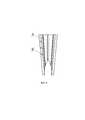
В частном случае реализации заявляемого устройства загрузочная горловина может быть выполнена составной, по меньшей мере, из двух элементов с разъемом по вертикали, на торцах которых выполнены поперечные пазы, образующие воздухоотводящие каналы. Также загрузочная горловина может быть изготовлена цельной с равномерно распределенными на ее стенке сквозными отверстиями.In the particular case of the implementation of the inventive device, the loading neck can be made integral of at least two elements with a vertical connector, at the ends of which there are transverse grooves forming air exhaust channels. Also, the filler neck can be made integral with through holes evenly distributed on its wall.
За счет удаления воздуха из предварительно уплотняемого материала повышается прочность готового брикета и исключается его расслоение.Due to the removal of air from the pre-compacted material, the strength of the finished briquette increases and its delamination is eliminated.
Конструктивно оси ведомых валков установлены в вертикальных опорах, смонтированных на раме с возможностью ограниченного смещения в горизонтальной плоскости в направлении к ведущему валку.Structurally, the axis of the driven rolls are mounted in vertical supports mounted on the frame with the possibility of limited displacement in the horizontal plane in the direction of the drive roll.
Предпочтительно снабдить устройство механизмами прижима ведомых валков к ведущему валку. При этом каждый механизм прижима валков выполнен в виде неподвижно смонтированной на раме стойки, по меньшей мере, с одним поперечным сквозным резьбовым отверстием и вкрученного в него регулировочного болта, концевой частью контактирующего с опорой валка.It is preferable to provide the device with mechanisms for clamping the driven rolls to the drive roll. Moreover, each roll clamping mechanism is made in the form of a rack fixedly mounted on the frame of the rack, with at least one transverse through threaded hole and an adjustment bolt screwed into it, the end part of the roller contacting with the support.
Наличие в устройстве механизма прижима валков позволяет при монтажных работах упростить регулировку взаимного расположения валков с целью обеспечения совпадения краев формующих ячеек по периметру с образованием замкнутой ячейки.The presence of a roll clamp mechanism in the device makes it possible to simplify the adjustment of the relative position of the rolls during installation to ensure that the edges of the forming cells coincide along the perimeter with the formation of a closed cell.
Краткое описание чертежейBrief Description of the Drawings
Сущность заявляемого технического решения поясняется чертежами, на которых изображено:The essence of the proposed technical solution is illustrated by drawings, which depict:
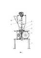
на фиг. 1 - заявляемое устройство, продольный разрез;in FIG. 1 - the claimed device, a longitudinal section;
на фиг. 2 - расположение валков, вид сверху;in FIG. 2 - the location of the rolls, top view;
на фиг. 3 - вид А на фиг. 1;in FIG. 3 is a view A in FIG. 1;
на фиг. 4 - элемент загрузочной горловины;in FIG. 4 - element of the loading neck;
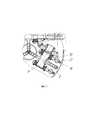
на фиг. 5 - механизм прижима ведомых валков.in FIG. 5 - clamping mechanism of driven rolls.
Осуществление изобретенияThe implementation of the invention
Устройство для брикетирования порошкообразных материалов содержит установленные на раме 1 с возможностью встречного вращения три приводных валка 2 с формующими ячейками 3 и загрузочный бункер 4 с коническим шнековым питателем 5 и пальчиковым ворошителем 6. Оси 7, 8, 9 валков 2 смонтированы в вертикальных опорах 10 и расположены в одной горизонтальной плоскости под углом 120° друг к другу.A device for briquetting powdered materials contains three
Привод устройства выполнен в виде конической зубчатой передачи. На ведущей оси 7 по обе стороны от валка 2 закреплены два ведущих конических зубчатых колеса 11, каждое из которых контактирует с ведомым коническим зубчатым колесом 12, смонтированным на оси 8, 9 близлежащего валка. Привод вращения валков осуществляется электродвигателем 13.The drive of the device is made in the form of a bevel gear. Two leading
В нижней части загрузочного бункера 4 смонтирована коническая загрузочная горловина 14. Конусность загрузочной горловины и шнекового питателя 5 составляет 8°. Загрузочная горловина 14 выполнена составной из трех элементов 15 с разъемом по вертикали. На торцах элементов загрузочной горловины выполнены поперечные пазы 16, образующие воздухоотводящие каналы.In the lower part of the
Опоры 10 осей 8, 9 ведомых валков смонтированы на раме 1 с возможностью ограниченного смещения в горизонтальной плоскости в направлении к ведущему валку.The
Устройство снабжено механизмами прижима ведомых валков к ведущему валку. Каждый механизм прижима валков выполнен в виде неподвижно смонтированной на раме 1 стойки 17 с двумя поперечными сквозными резьбовыми отверстиями (не показаны) и вкрученных в них регулировочных болтов 18, концевой частью контактирующими с опорой 10 валка.The device is equipped with mechanisms for clamping the driven rolls to the drive roll. Each roll clamping mechanism is made in the form of a
Заявляемое устройство работает следующим образом.The inventive device operates as follows.
Изначально валки 2 выставляют на осях 7, 8, 9 таким образом, чтобы при смыкании формующие ячейки 3, расположенные на их рабочих поверхностях, находились друг напротив друга. При соблюдении этого условия обеспечивается полное совпадение краев формующих ячеек по периметру с образованием замкнутой формы для прессования брикета.Initially, the
Подлежащий брикетированию порошковый материал поступает в загрузочный бункер 4 через загрузочный патрубок 19. При включении привода шнекового питателя 5 пальчиковый ворошитель 6, смонтированный на его валу, рыхлит порошок, препятствуя его зависанию в бункере 4. Конический шнековый питатель 5, продвигая материал вдоль конической загрузочной горловины 14, предварительно уплотняет его, подает под давлением в межвалковое пространство и заполняет формующие ячейки 3.The powder material to be briquetted enters the
Формующие ячейки 3 при вращении валков 2 сближаются, производя обжатие брикетируемого материала с трех сторон. В итоге получаются плотные и прочные брикеты. При дальнейшем повороте валков 2 отпрессованные брикеты под действием силы тяжести и центробежной силы выпадают из ячеек 3 и направляются для последующей обработки.The forming
Благодаря использованию заявляемого устройства для брикетирования порошкообразного материала повышается плотность и прочность получаемых брикетов, что расширяет функциональные возможности их использования при производстве строительных материалов, а также обеспечивается эксплуатационная надежность привода устройства.Thanks to the use of the inventive device for briquetting powdered material, the density and strength of the resulting briquettes increases, which expands the functionality of their use in the production of building materials, and also ensures the operational reliability of the drive device.
Claims (8)
Translated fromRussianPriority Applications (1)
| Application Number | Priority Date | Filing Date | Title |
|---|---|---|---|
| RU2019140322ARU2719208C1 (en) | 2019-12-06 | 2019-12-06 | Device for briquetting powder materials |
Applications Claiming Priority (1)
| Application Number | Priority Date | Filing Date | Title |
|---|---|---|---|
| RU2019140322ARU2719208C1 (en) | 2019-12-06 | 2019-12-06 | Device for briquetting powder materials |
Publications (1)
| Publication Number | Publication Date |
|---|---|
| RU2719208C1true RU2719208C1 (en) | 2020-04-17 |
Family
ID=70277762
Family Applications (1)
| Application Number | Title | Priority Date | Filing Date |
|---|---|---|---|
| RU2019140322ARU2719208C1 (en) | 2019-12-06 | 2019-12-06 | Device for briquetting powder materials |
Country Status (1)
| Country | Link |
|---|---|
| RU (1) | RU2719208C1 (en) |
Cited By (1)
| Publication number | Priority date | Publication date | Assignee | Title |
|---|---|---|---|---|
| RU215690U1 (en)* | 2022-04-20 | 2022-12-22 | Российская Федерация, от имени которой выступает Государственная корпорация по атомной энергии "Росатом" (Госкорпорация "Росатом") | Press powder granulator for robotic line |
Citations (6)
| Publication number | Priority date | Publication date | Assignee | Title |
|---|---|---|---|---|
| SU98317A1 (en)* | 1952-05-16 | 1953-11-30 | Б.М. Изаксон | The method of making bricks and device for implementing the method |
| SU633747A1 (en)* | 1977-05-23 | 1978-11-25 | Калининский Ордена Трудового Красного Знамени Политехнический Институт | Roller-type briquetting press |
| CN101784683A (en)* | 2007-09-18 | 2010-07-21 | 株式会社神户制钢所 | Method for producing briquette with carbonaceous material incorporated therein by use of oil-containing iron-making plant dust |
| RU2450930C2 (en)* | 2010-08-02 | 2012-05-20 | Закрытое акционерное общество "Управляющая компания "НКА-Холдинг" | Roll extruder for pelletising polydisperse loose materials |
| EP2505346A1 (en)* | 2009-11-27 | 2012-10-03 | Mitsui Engineering & Shipbuilding Co., Ltd. | Cheek plate equipped with wedge wire screen |
| WO2015198903A1 (en)* | 2014-06-23 | 2015-12-30 | 新東工業株式会社 | Briquette machine |
- 2019
- 2019-12-06RURU2019140322Apatent/RU2719208C1/enactive
Patent Citations (6)
| Publication number | Priority date | Publication date | Assignee | Title |
|---|---|---|---|---|
| SU98317A1 (en)* | 1952-05-16 | 1953-11-30 | Б.М. Изаксон | The method of making bricks and device for implementing the method |
| SU633747A1 (en)* | 1977-05-23 | 1978-11-25 | Калининский Ордена Трудового Красного Знамени Политехнический Институт | Roller-type briquetting press |
| CN101784683A (en)* | 2007-09-18 | 2010-07-21 | 株式会社神户制钢所 | Method for producing briquette with carbonaceous material incorporated therein by use of oil-containing iron-making plant dust |
| EP2505346A1 (en)* | 2009-11-27 | 2012-10-03 | Mitsui Engineering & Shipbuilding Co., Ltd. | Cheek plate equipped with wedge wire screen |
| RU2450930C2 (en)* | 2010-08-02 | 2012-05-20 | Закрытое акционерное общество "Управляющая компания "НКА-Холдинг" | Roll extruder for pelletising polydisperse loose materials |
| WO2015198903A1 (en)* | 2014-06-23 | 2015-12-30 | 新東工業株式会社 | Briquette machine |
Cited By (2)
| Publication number | Priority date | Publication date | Assignee | Title |
|---|---|---|---|---|
| RU215690U1 (en)* | 2022-04-20 | 2022-12-22 | Российская Федерация, от имени которой выступает Государственная корпорация по атомной энергии "Росатом" (Госкорпорация "Росатом") | Press powder granulator for robotic line |
| RU2813529C1 (en)* | 2023-03-20 | 2024-02-12 | Федеральное государственное бюджетное образовательное учреждение высшего образования "Кубанский государственный аграрный университет имени И.Т. Трубилина" | Feeder for granulator |
Similar Documents
| Publication | Publication Date | Title |
|---|---|---|
| RU2719208C1 (en) | Device for briquetting powder materials | |
| JP2022553064A (en) | Tablet press machine and compression method | |
| US4083912A (en) | Process for the compression of black powder | |
| US5073323A (en) | Method and apparatus for producing compacted particulate articles | |
| CN112368138B (en) | Method for producing a compact and arrangement for producing a compact | |
| CN104772923B (en) | Modularity plunger type biomass forming machine | |
| JPS5859291A (en) | Artificial fuel cube and manufacture | |
| KR101253957B1 (en) | Forming Apparatus and Method | |
| CN212920576U (en) | Ball press machine system for dry pressing forming | |
| US20050035479A1 (en) | Method and apparatus for manufacturing multi-layer press molded bodies | |
| AU2001287865A1 (en) | Method and apparatus for manufacturing multi-layer press molded bodies | |
| CN211105870U (en) | Ball machine feeding device is pressed to dry process | |
| JPS59150699A (en) | Roller compactor | |
| CN217373596U (en) | High-pressure ball press machine for sludge ball production in steel mill | |
| JPS6051960B2 (en) | roller compactor | |
| CN214569267U (en) | Ball machine feeding device is pressed to dry process | |
| US3049760A (en) | Method and apparatus for mass-producing small balls of plastic materials | |
| CN216354343U (en) | Core flattening device for electronic product production and processing | |
| CN2445907Y (en) | Briquette shaping machine | |
| RU2032535C1 (en) | Method for layer-by-layer manufacture of building products and plant for its realization | |
| CN101406958B (en) | Device for granulating high-specific gravity tungsten alloy powder | |
| CN220160480U (en) | Raw material screening device for semi-coke production | |
| CN220514107U (en) | Anti-accumulation granulator | |
| CN113234506B (en) | Briquette forming processing machinery and method | |
| CN213733576U (en) | Last pre-compaction wheel structure of powder pelleter |