RU2718620C2 - Transcranial fastener for drainage catheters - Google Patents
Transcranial fastener for drainage cathetersDownload PDFInfo
- Publication number
- RU2718620C2 RU2718620C2RU2017125215ARU2017125215ARU2718620C2RU 2718620 C2RU2718620 C2RU 2718620C2RU 2017125215 ARU2017125215 ARU 2017125215ARU 2017125215 ARU2017125215 ARU 2017125215ARU 2718620 C2RU2718620 C2RU 2718620C2
- Authority
- RU
- Russia
- Prior art keywords
- channel
- movement
- drainage catheter
- transcranial
- catheter
- Prior art date
Links
- 230000007246mechanismEffects0.000claimsabstractdescription34
- 230000000903blocking effectEffects0.000claimsabstractdescription13
- 210000000988bone and boneAnatomy0.000claimsdescription3
- 238000007373indentationMethods0.000claimsdescription2
- 230000003993interactionEffects0.000claimsdescription2
- 230000000284resting effectEffects0.000claimsdescription2
- 230000002269spontaneous effectEffects0.000claimsdescription2
- 230000009897systematic effectEffects0.000claims1
- 210000001519tissueAnatomy0.000abstractdescription5
- 210000003625skullAnatomy0.000abstractdescription4
- 230000000694effectsEffects0.000abstract1
- 230000035876healingEffects0.000abstract1
- 239000000126substanceSubstances0.000abstract1
- 238000000034methodMethods0.000description3
- 230000008901benefitEffects0.000description2
- 238000000605extractionMethods0.000description2
- 238000003780insertionMethods0.000description2
- 230000037431insertionEffects0.000description2
- 239000000463materialSubstances0.000description2
- 206010009719CNS ventriculitisDiseases0.000description1
- 208000002667Subdural HematomaDiseases0.000description1
- 208000027418Wounds and injuryDiseases0.000description1
- 239000000853adhesiveSubstances0.000description1
- 230000001070adhesive effectEffects0.000description1
- 210000004369bloodAnatomy0.000description1
- 239000008280bloodSubstances0.000description1
- 210000004556brainAnatomy0.000description1
- 210000001175cerebrospinal fluidAnatomy0.000description1
- 230000015271coagulationEffects0.000description1
- 238000005345coagulationMethods0.000description1
- 230000001419dependent effectEffects0.000description1
- 210000001951dura materAnatomy0.000description1
- 230000008030eliminationEffects0.000description1
- 238000003379elimination reactionMethods0.000description1
- 208000003906hydrocephalusDiseases0.000description1
- 238000012986modificationMethods0.000description1
- 230000004048modificationEffects0.000description1
- 230000001575pathological effectEffects0.000description1
- 230000008569processEffects0.000description1
- 238000011084recoveryMethods0.000description1
Images

Classifications
- A—HUMAN NECESSITIES
- A61—MEDICAL OR VETERINARY SCIENCE; HYGIENE
- A61M—DEVICES FOR INTRODUCING MEDIA INTO, OR ONTO, THE BODY; DEVICES FOR TRANSDUCING BODY MEDIA OR FOR TAKING MEDIA FROM THE BODY; DEVICES FOR PRODUCING OR ENDING SLEEP OR STUPOR
- A61M25/00—Catheters; Hollow probes
- A61M25/01—Introducing, guiding, advancing, emplacing or holding catheters
- A61M25/02—Holding devices, e.g. on the body
- A61M25/04—Holding devices, e.g. on the body in the body, e.g. expansible
- A—HUMAN NECESSITIES
- A61—MEDICAL OR VETERINARY SCIENCE; HYGIENE
- A61M—DEVICES FOR INTRODUCING MEDIA INTO, OR ONTO, THE BODY; DEVICES FOR TRANSDUCING BODY MEDIA OR FOR TAKING MEDIA FROM THE BODY; DEVICES FOR PRODUCING OR ENDING SLEEP OR STUPOR
- A61M27/00—Drainage appliance for wounds or the like, i.e. wound drains, implanted drains
- A61M27/002—Implant devices for drainage of body fluids from one part of the body to another
- A61M27/006—Cerebrospinal drainage; Accessories therefor, e.g. valves
- A—HUMAN NECESSITIES
- A61—MEDICAL OR VETERINARY SCIENCE; HYGIENE
- A61M—DEVICES FOR INTRODUCING MEDIA INTO, OR ONTO, THE BODY; DEVICES FOR TRANSDUCING BODY MEDIA OR FOR TAKING MEDIA FROM THE BODY; DEVICES FOR PRODUCING OR ENDING SLEEP OR STUPOR
- A61M39/00—Tubes, tube connectors, tube couplings, valves, access sites or the like, specially adapted for medical use
- A61M39/02—Access sites
- A61M39/0247—Semi-permanent or permanent transcutaneous or percutaneous access sites to the inside of the body
- A—HUMAN NECESSITIES
- A61—MEDICAL OR VETERINARY SCIENCE; HYGIENE
- A61B—DIAGNOSIS; SURGERY; IDENTIFICATION
- A61B90/00—Instruments, implements or accessories specially adapted for surgery or diagnosis and not covered by any of the groups A61B1/00 - A61B50/00, e.g. for luxation treatment or for protecting wound edges
- A61B90/10—Instruments, implements or accessories specially adapted for surgery or diagnosis and not covered by any of the groups A61B1/00 - A61B50/00, e.g. for luxation treatment or for protecting wound edges for stereotaxic surgery, e.g. frame-based stereotaxis
- A61B2090/103—Cranial plugs for access to brain
- A—HUMAN NECESSITIES
- A61—MEDICAL OR VETERINARY SCIENCE; HYGIENE
- A61M—DEVICES FOR INTRODUCING MEDIA INTO, OR ONTO, THE BODY; DEVICES FOR TRANSDUCING BODY MEDIA OR FOR TAKING MEDIA FROM THE BODY; DEVICES FOR PRODUCING OR ENDING SLEEP OR STUPOR
- A61M25/00—Catheters; Hollow probes
- A61M25/01—Introducing, guiding, advancing, emplacing or holding catheters
- A61M25/02—Holding devices, e.g. on the body
- A61M2025/0213—Holding devices, e.g. on the body where the catheter is attached by means specifically adapted to a part of the human body
- A—HUMAN NECESSITIES
- A61—MEDICAL OR VETERINARY SCIENCE; HYGIENE
- A61M—DEVICES FOR INTRODUCING MEDIA INTO, OR ONTO, THE BODY; DEVICES FOR TRANSDUCING BODY MEDIA OR FOR TAKING MEDIA FROM THE BODY; DEVICES FOR PRODUCING OR ENDING SLEEP OR STUPOR
- A61M25/00—Catheters; Hollow probes
- A61M25/01—Introducing, guiding, advancing, emplacing or holding catheters
- A61M25/02—Holding devices, e.g. on the body
- A61M2025/028—Holding devices, e.g. on the body having a mainly rigid support structure
- A—HUMAN NECESSITIES
- A61—MEDICAL OR VETERINARY SCIENCE; HYGIENE
- A61M—DEVICES FOR INTRODUCING MEDIA INTO, OR ONTO, THE BODY; DEVICES FOR TRANSDUCING BODY MEDIA OR FOR TAKING MEDIA FROM THE BODY; DEVICES FOR PRODUCING OR ENDING SLEEP OR STUPOR
- A61M39/00—Tubes, tube connectors, tube couplings, valves, access sites or the like, specially adapted for medical use
- A61M39/02—Access sites
- A61M39/0247—Semi-permanent or permanent transcutaneous or percutaneous access sites to the inside of the body
- A61M2039/025—Semi-permanent or permanent transcutaneous or percutaneous access sites to the inside of the body through bones or teeth, e.g. through the skull
- A—HUMAN NECESSITIES
- A61—MEDICAL OR VETERINARY SCIENCE; HYGIENE
- A61M—DEVICES FOR INTRODUCING MEDIA INTO, OR ONTO, THE BODY; DEVICES FOR TRANSDUCING BODY MEDIA OR FOR TAKING MEDIA FROM THE BODY; DEVICES FOR PRODUCING OR ENDING SLEEP OR STUPOR
- A61M39/00—Tubes, tube connectors, tube couplings, valves, access sites or the like, specially adapted for medical use
- A61M39/02—Access sites
- A61M39/0247—Semi-permanent or permanent transcutaneous or percutaneous access sites to the inside of the body
- A61M2039/0273—Semi-permanent or permanent transcutaneous or percutaneous access sites to the inside of the body for introducing catheters into the body
- A—HUMAN NECESSITIES
- A61—MEDICAL OR VETERINARY SCIENCE; HYGIENE
- A61M—DEVICES FOR INTRODUCING MEDIA INTO, OR ONTO, THE BODY; DEVICES FOR TRANSDUCING BODY MEDIA OR FOR TAKING MEDIA FROM THE BODY; DEVICES FOR PRODUCING OR ENDING SLEEP OR STUPOR
- A61M39/00—Tubes, tube connectors, tube couplings, valves, access sites or the like, specially adapted for medical use
- A61M39/02—Access sites
- A61M39/0247—Semi-permanent or permanent transcutaneous or percutaneous access sites to the inside of the body
- A61M2039/0294—Semi-permanent or permanent transcutaneous or percutaneous access sites to the inside of the body having a specific shape matching the shape of a tool to be inserted therein, e.g. for easy introduction, for sealing purposes, guide
- A—HUMAN NECESSITIES
- A61—MEDICAL OR VETERINARY SCIENCE; HYGIENE
- A61M—DEVICES FOR INTRODUCING MEDIA INTO, OR ONTO, THE BODY; DEVICES FOR TRANSDUCING BODY MEDIA OR FOR TAKING MEDIA FROM THE BODY; DEVICES FOR PRODUCING OR ENDING SLEEP OR STUPOR
- A61M2202/00—Special media to be introduced, removed or treated
- A61M2202/04—Liquids
- A61M2202/0464—Cerebrospinal fluid
Landscapes
- Health & Medical Sciences (AREA)
- Life Sciences & Earth Sciences (AREA)
- Heart & Thoracic Surgery (AREA)
- Engineering & Computer Science (AREA)
- Biomedical Technology (AREA)
- Public Health (AREA)
- Hematology (AREA)
- Animal Behavior & Ethology (AREA)
- General Health & Medical Sciences (AREA)
- Anesthesiology (AREA)
- Veterinary Medicine (AREA)
- Biophysics (AREA)
- Pulmonology (AREA)
- Otolaryngology (AREA)
- Neurology (AREA)
- Gastroenterology & Hepatology (AREA)
- Ophthalmology & Optometry (AREA)
- External Artificial Organs (AREA)
- Media Introduction/Drainage Providing Device (AREA)
Abstract
Description
Translated fromRussianНастоящее изобретение относят к транскраниальному крепежному устройству для дренажных катетеров.The present invention relates to a transcranial fastening device for drainage catheters.
Известно, что для лечения определенных патологических состояний головного мозга, таких как, например, субдуральные гематомы, вентрикулит или гидроцефалия, необходимо ввести через кожу и кости черепа по меньшей мере одну дренажную трубку или катетер для отсасывания и удаления крови или спинномозговой жидкости, отправки ее в сборный резервуар.It is known that for the treatment of certain pathological conditions of the brain, such as, for example, subdural hematomas, ventriculitis, or hydrocephalus, it is necessary to introduce at least one drainage tube or catheter through the skin and bones of the skull to suck and remove blood or cerebrospinal fluid, sending it to collection tank.
Поэтому, чтобы создать транскраниальный канал и вставить указанную дренажную трубку, обычно необходимо провести нейрохирургическую операцию путем перфорации сверлом свода черепа, с последующей коагуляцией и разрезом твердой мозговой оболочки.Therefore, in order to create a transcranial canal and insert the specified drainage tube, it is usually necessary to carry out a neurosurgical operation by perforating the cranial vault with a drill, followed by coagulation and incision of the dura mater.
Примеры известных способов, процессов и инструментов, связанных с такими операциями, раскрыты, например, в CN-A-202604860, DE-A-102005013720, CN-A-201389060, CN-A-201 108493, US-A-6673022.Examples of known methods, processes and tools associated with such operations are disclosed, for example, in CN-A-202604860, DE-A-102005013720, CN-A-201389060, CN-A-201 108493, US-A-6673022.
Однако среди таких известных способов отсутствует устройство, предотвращающее случайное выпадение введенной дренажной трубки из транскраниального канала, что требует, к сожалению, проведения нового нейрохирургического вмешательства для ее повторного введения с соответствующими очевидными проблемами у пациента.However, among such known methods, there is no device to prevent the accidentally falling out of the inserted drainage tube from the transcranial canal, which, unfortunately, requires a new neurosurgical intervention to re-introduce it with the corresponding obvious problems in the patient.
Кроме того, известные решения, подобные описанным выше, обычно не допускают эстетически приемлемого закрытия раны, так как нередко кожная ткань вблизи транскраниального канала имеет тенденцию образовывать углубления.In addition, well-known solutions, such as those described above, usually do not allow aesthetically acceptable closure of the wound, since often skin tissue near the transcranial canal tends to form depressions.
Следовательно, целью настоящего изобретения является решение вышеупомянутых проблем известного уровня техники с помощью транскраниального крепежного устройства для дренажных катетеров для предотвращения их непреднамеренного удаления.Therefore, an object of the present invention is to solve the aforementioned problems of the prior art using a transcranial fastening device for drainage catheters to prevent their inadvertent removal.
Другой целью настоящего изобретения является создание транскраниального крепежного устройства, при помощи которого достигается закрытие транскраниального канала, заживление кожной ткани и эстетически лучший результат по сравнению с тем, что предлагают системы известного уровня техники.Another objective of the present invention is to provide a transcranial fastening device with which the transcranial canal is closed, skin tissue heals and aesthetically better result compared to what is known in the art.
Вышеупомянутые и другие цели и преимущества изобретения, как будет видно из последующего описания, достигают с помощью устройства, как заявлено в п. 1, Предпочтительные варианты реализации и нетривиальные разновидности настоящего изобретения являются предметом зависимых пунктов формулы изобретения.The above and other objects and advantages of the invention, as will be seen from the following description, are achieved by the device as claimed in claim 1. Preferred embodiments and non-trivial variations of the present invention are the subject of the dependent claims.
Предполагается, что все прилагаемые формулы являются неотъемлемой частью настоящего описания. Очевидно, что многочисленные варианты и модификации (например, связанные с формой, размерами, расположениями и деталями с эквивалентной функциональностью) могут быть выполнены так, как описано, в пределах объема изобретения, как видно из прилагаемой формулы изобретения.It is assumed that all the attached formulas are an integral part of the present description. It is obvious that numerous variations and modifications (for example, associated with the shape, size, layout and parts with equivalent functionality) can be performed as described, within the scope of the invention, as can be seen from the attached claims.
Настоящее изобретение будет лучше описано в некоторых предпочтительных вариантах его осуществления, представленных в качестве неограничивающего примера со ссылкой на прилагаемые чертежи, на которых:The present invention will be better described in some preferred variants of its implementation, presented as a non-limiting example with reference to the accompanying drawings, in which:
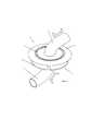
На Фиг. 1 изображен вид в перспективе сверху предпочтительного варианта осуществления транскраниального крепежного устройства для дренажных катетеров в соответствии с настоящим изобретением;In FIG. 1 is a top perspective view of a preferred embodiment of a transcranial fastening device for drainage catheters in accordance with the present invention;
На Фиг. 2а изображен вид сбоку в разрезе устройства в соответствии с настоящим изобретением в первом рабочем положении;In FIG. 2a is a sectional side view of a device in accordance with the present invention in a first operating position;
На Фиг. 2b изображен вид сбоку в разрезе устройства в соответствии с настоящим изобретением во втором рабочем положении; иIn FIG. 2b is a sectional side view of a device in accordance with the present invention in a second operating position; and
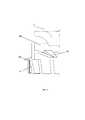
На Фиг. 3 изображен вариант устройства в соответствии с настоящим изобретением.In FIG. 3 shows an embodiment of a device in accordance with the present invention.
Относительно Фигур можно отметить, что устройство (1) согласно настоящего изобретения, предназначенное, в частности, для транскраниального крепления по меньшей мере одного дренажного катетера (3), содержит:Regarding the Figures, it can be noted that the device (1) according to the present invention, intended, in particular, for transcranial attachment of at least one drainage catheter (3), contains:
- по меньшей мере один наружный корпус (5), выполненный с возможностью установки внутри просверленного транскраниального отверстия, при этом наружный корпус (5) имеет по меньшей мере один канал Р для дренажного катетера (3), проходящий через наружный корпус (5), причем канал Р оснащен блокирующим механизмом (9) дренажного катетера (3), выполненным с возможностью обеспечения прохождения дренажного катетера (3) через канал Р в первом направлении движения (M1) (соответствующее направлению введения дренажного катетера (3) внутрь черепа через просверленное транскраниальное отверстие) и который предотвращает прохождение дренажного катетера (3) через тот же канал (Р) во втором направлении движения (М2) (соответствующее направлению извлечения дренажного катетера (3) из черепа наружу через просверленное транскраниальное отверстие);at least one outer casing (5) configured to fit inside the drilled transcranial opening, wherein the outer casing (5) has at least one channel P for a drainage catheter (3) passing through the outer casing (5), wherein the channel P is equipped with a blocking mechanism (9) of the drainage catheter (3), configured to allow the passage of the drainage catheter (3) through the channel P in the first direction of movement (M1) (corresponding to the direction of insertion of the drainage catheter (3) into the skull through the drill Noe transcranial hole) and which prevents the passage of the drainage catheter (3) through the same channel (R) in a second direction of movement (M2) (corresponding to the direction of extraction of the drainage catheter (3) to the outside of the skull through the drilled hole transcranial);
- по меньшей мере, одним приводным механизмом (7), функционально взаимодействующим с блокирующим механизмом (9) и выполненным с возможностью переключения из первого рабочего положения (как показано, например, на фигуре 2а), которое предпочтительно соответствует его спонтанному положению покоя, при этом блокирующий механизм (9) не допускает продвижение дренажного катетера (3) через канал (Р) наружного корпуса (5) по второму направлению движения (М2), во второе рабочее положение (как показано, например, на фигуре 2b), в котором блокирующий механизм 9 позволяет продвижение дренажного катетера (3) через канал (Р) наружного корпуса (5) по второму направлению движения (М2).- at least one drive mechanism (7), functionally interacting with the locking mechanism (9) and configured to switch from the first working position (as shown, for example, in figure 2a), which preferably corresponds to its spontaneous resting position, while the blocking mechanism (9) prevents the drainage catheter (3) from moving through the channel (P) of the outer casing (5) in the second direction of movement (M2), into the second working position (as shown, for example, in figure 2b), in which the blocking mechanism 9 p Allows the advancement of the drainage catheter (3) through the channel (P) of the outer casing (5) in the second direction of movement (M2).
Предпочтительно, наружный корпус (5) может быть оснащен креплениями к костным стенкам по периметру просверленного транскраниального отверстия, для укрепления соединения устройства (1) согласно настоящему изобретению с этим отверстием.Preferably, the outer casing (5) can be equipped with fastenings to the bone walls around the perimeter of the drilled transcranial opening, to strengthen the connection of the device (1) according to the present invention with this opening.
Предпочтительно, крепления содержат по меньшей мере один профиль (11) с прорезью, расположенный на внешней поверхности наружного корпуса (5), причем такой профиль (11) с прорезью является достаточно эластичным, чтобы гарантировать адекватный механический захват ткани коечных стенок но периметру просверленною транскраниального отверстия. Очевидно, что крепления могут быть изготовлены любым другим способом, подходящим для этой цели, также включая использование склеивающих веществ, находясь таким образом в рамках объема настоящего изобретения.Preferably, the fasteners contain at least one profile (11) with a slot located on the outer surface of the outer casing (5), and such a profile (11) with a slot is elastic enough to guarantee adequate mechanical grip of the tissue of the bed walls but the perimeter of the drilled transcranial hole . Obviously, the fasteners can be made in any other way suitable for this purpose, also including the use of adhesives, thus being within the scope of the present invention.
Кроме того, чтобы избежать чрезмерного введения устройства (1) согласно настоящему изобретению внутрь просверленного отверстия, оно может содержать по меньшей мере один опорный профиль (13), радиально расположенный вокруг внешнего корпуса (5), чтобы упираться в наружную поверхность свода черепа, примыкающую к самому просверленному отверстию.In addition, in order to avoid excessive insertion of the device (1) according to the present invention into the drilled hole, it may contain at least one support profile (13) radially located around the outer case (5) so as to abut against the outer surface of the cranial vault adjacent to the most drilled hole.
Согласно настоящему изобретению блокирующий механизм (9) содержит множество однонаправленных эластичных крыльев (15), радиально расположенных вокруг канала (Р) наружною корпуса (5) и соответственно ориентированных таким образом, чтобы образовать кольцо для прохождения дренажного катетера (3), в основном коаксиально каналу (Р), и формировать изгиб в сторону продвижения дренажного катетера (3) по первому направлению движения (M1) через канал (Р) и кольцо и, без вмешательства приводного механизма (7), который спонтанно находится в первом рабочем положении и блокирует эластичные крылья (15) на внешней поверхности дренажного катетера (3), для предотвращения продвижения дренажного катетера (3) по второму направлению движения (М2) через сам канал.According to the present invention, the blocking mechanism (9) comprises a plurality of unidirectional elastic wings (15) radially arranged around the channel (P) of the outer casing (5) and accordingly oriented so as to form a ring for the passage of the drainage catheter (3), mainly coaxial to the channel (P), and form a bend in the direction of advancement of the drainage catheter (3) in the first direction of movement (M1) through the channel (P) and the ring and, without the intervention of the drive mechanism (7), which is spontaneously located in the first working floor It blocks and blocks the elastic wings (15) on the outer surface of the drainage catheter (3), to prevent the drainage catheter (3) from moving in the second direction of movement (M2) through the channel itself.
Преимущественно, приводной механизм (7), функционально взаимодействующий с блокирующим механизмом (9) в виде однонаправленных гибких крыльев (15), состоит, таким образом, предпочтительно из по меньшей мере одного подвижного элемента (17), аксиально скользящего внутри канала (Р) наружного корпуса (5) по направлению М1-М2 и имеющего по меньшей мере одно сквозное отверстие (19), коаксиальное каналу (Р), которое должен пересекать дренажный катетер (3); подвижный элемент (17) дополнительно снабжен по меньшей мере одной опорной частью (21), взаимодействующей с однонаправленными гибкими крыльями (15) так, что когда внешняя сила направленная вдоль первого направления движения (M1), воздействует на подвижный элемент (17), последний переключается с первого рабочего положения (как показано, например, на фигуре 2а), во второе рабочее положение (как показано, например, на фигуре 2b), в котором взаимодействие опорной части (21) с крыльями (15) эластично раскрывает последние, с последующим увеличением окружности для прохождения так, чтобы обеспечить прохождение дренажного катетера (3) через канал (Р) наружного корпуса (5) и, в частности, через сквозное отверстие (19) подвижного элемента (17) по второму направлению движения (M2).Advantageously, the drive mechanism (7), operatively interacting with the blocking mechanism (9) in the form of unidirectional flexible wings (15), thus preferably consists of at least one movable element (17) axially sliding inside the channel (P) of the outer body (5) in the direction M1-M2 and having at least one through hole (19), coaxial to the channel (P), which must cross the drainage catheter (3); the movable element (17) is further provided with at least one supporting part (21) interacting with unidirectional flexible wings (15) so that when an external force directed along the first direction of movement (M1) acts on the movable element (17), the latter switches from the first working position (as shown, for example, in figure 2a), to the second working position (as shown, for example, in figure 2b), in which the interaction of the support part (21) with the wings (15) elastically opens the latter, with subsequent increase circumference to pass so as to ensure that the drainage catheter (3) through the passageway (P) of the outer housing (5) and, in particular, through the through hole (19) of the movable member (17) in the second direction of movement (M2).
Как только действие внешней силы прекратилось, эластичность крыльев (15), действующих на опорную часть (21), возвращает подвижный элемент (17) в его первое рабочее положение: преимущественно в первом рабочем положении, которое также сохраняется после того, как дренажный катетер (3) полностью извлекают, наружная поверхность S' подвижного элемента (17) совпадает с наружной поверхностью S'' наружного корпуса (5) и, возможно, с опорным профилем (13), так что кожная ткань над устройством (1) согласно настоящему изобретению не образует неэстетичные углубления.As soon as the external force has stopped, the elasticity of the wings (15) acting on the support part (21) returns the movable element (17) to its first working position: mainly in the first working position, which also remains after the drainage catheter (3 ) is completely removed, the outer surface S 'of the movable element (17) coincides with the outer surface S' 'of the outer casing (5) and possibly with the supporting profile (13), so that the skin tissue above the device (1) according to the present invention does not form unaesthetic recesses I am.
Предпочтительно наружный корпус (5) выполнен в виде внешней втулки из любого материала из пластмассы, подходящего для этой цели. Более того, тот же подвижный элемент (17) может быть выполнен в виде внутренней втулки к каналу (Р) наружного корпуса (5) из любого материала из пластмассы, подходящего для этой цели.Preferably, the outer casing (5) is made in the form of an outer sleeve of any plastic material suitable for this purpose. Moreover, the same movable element (17) can be made in the form of an inner sleeve to the channel (P) of the outer casing (5) of any plastic material suitable for this purpose.
Устройство (1) соответственно настоящему изобретению, выполненное в зависимости от того, что было описано выше, затем вставляют в просверленное отверстие, где его стабильно закрепляют, возможно, также при помощи креплений наружного корпуса (5): приводной механизм (7) находится, предпочтительно спонтанно, в первом рабочем положении, и блокирующий механизм (9), и в особенности однонаправленные эластичные крылья (15) позволяют ввести дренажный катетер (3) через канал (Р) и в частности через сквозное отверстие (19) подвижного элемента (17) до оптимального положения, предотвращая его обратное извлечение, более того существенным преимуществом является исключение случайного извлечения самого катетера (3).The device (1) according to the present invention, made depending on what has been described above, is then inserted into the drilled hole where it is stably fixed, possibly also using the fasteners of the outer case (5): the drive mechanism (7) is preferably spontaneously, in the first operating position, and the locking mechanism (9), and in particular the unidirectional elastic wings (15), allow the drainage catheter (3) to be inserted through the channel (P) and in particular through the through hole (19) of the movable element (17) to optimally a position preventing its reverse recovery, more significant advantage is the elimination of accidental removal of the catheter (3).
Напротив, когда необходимо удалить дренажный катетер (3), достаточно повлиять на приводной механизм (7), например, путем приложения внешней силы, направленной вдоль первого направления движения (М1), при этом приводной механизм (7) переключается во второе рабочее положение и активирует блокирующий механизм (9), например, эластично раскрывая крылья (15), для обеспечения извлечения этого катетера (3) из просверленного отверстия через канал (Р) наружного корпуса (5).On the contrary, when it is necessary to remove the drainage catheter (3), it is enough to influence the drive mechanism (7), for example, by applying an external force directed along the first direction of movement (M1), while the drive mechanism (7) switches to the second working position and activates a blocking mechanism (9), for example, elastically opening the wings (15), to ensure the extraction of this catheter (3) from the drilled hole through the channel (P) of the outer casing (5).
Согласно варианту осуществления данного изобретения, изображенного на фигуре 3, устройство (1) состоит из трех отдельных компонентов: наружного корпуса (5), оснащенного опорным профилем (13); вставки (30), снабженной эластичными блокирующими крыльями (15), которые можно ввести под давлением внутрь наружною корпуса (5), чтобы расширить снаружи опорный профиль (13) для фиксации наружною корпуса (5) на своде черепа; и приводною механизма (7), позволяющею установить при вдавливании вставку (30) внутри внешнего корпуса (5).According to the embodiment of the present invention depicted in FIG. 3, the device (1) consists of three separate components: an outer casing (5) equipped with a support profile (13); inserts (30) equipped with elastic blocking wings (15), which can be inserted under pressure into the outer casing (5) to expand the support profile (13) from the outside to fix the outer casing (5) on the cranial vault; and a drive mechanism (7), allowing the insert (30) to be installed during indentation inside the outer case (5).
Claims (11)
Translated fromRussianApplications Claiming Priority (3)
| Application Number | Priority Date | Filing Date | Title |
|---|---|---|---|
| ITTO20150101 | 2015-02-16 | ||
| ITTO2015A000101 | 2015-02-16 | ||
| PCT/IT2016/000001WO2016132390A1 (en) | 2015-02-16 | 2016-01-07 | Transcranial fastening device for drainage catheters |
Publications (3)
| Publication Number | Publication Date |
|---|---|
| RU2017125215A RU2017125215A (en) | 2019-03-18 |
| RU2017125215A3 RU2017125215A3 (en) | 2019-07-17 |
| RU2718620C2true RU2718620C2 (en) | 2020-04-10 |
Family
ID=52633520
Family Applications (1)
| Application Number | Title | Priority Date | Filing Date |
|---|---|---|---|
| RU2017125215ARU2718620C2 (en) | 2015-02-16 | 2016-01-07 | Transcranial fastener for drainage catheters |
Country Status (7)
| Country | Link |
|---|---|
| US (1) | US10675445B2 (en) |
| EP (1) | EP3259011B1 (en) |
| CN (1) | CN107223063B (en) |
| BR (1) | BR112017015285B1 (en) |
| ES (1) | ES2695583T3 (en) |
| RU (1) | RU2718620C2 (en) |
| WO (1) | WO2016132390A1 (en) |
Families Citing this family (9)
| Publication number | Priority date | Publication date | Assignee | Title |
|---|---|---|---|---|
| US11426302B2 (en) | 2014-11-03 | 2022-08-30 | Fistula Solution Corporation | Containment devices for treatment of intestinal fistulas and complex wounds |
| US10052463B2 (en)* | 2016-09-12 | 2018-08-21 | Koucky & Volkodav Llc | Shunt systems and methods for removing excess cerebrospinal fluid |
| US11235133B2 (en) | 2017-01-24 | 2022-02-01 | Intuitive Surgical Operations, Inc. | Surgical instrument ports configured for use with wound retractors, and related devices and methods |
| US11439798B2 (en) | 2017-04-24 | 2022-09-13 | Longeviti Neuro Solutions Llc | Cerebral spinal fluid shunt plug |
| US11045632B2 (en) | 2017-04-24 | 2021-06-29 | Longeviti Neuro Solutions Llc | Cerebral spinal fluid shunt plug |
| US11207097B2 (en) | 2019-02-13 | 2021-12-28 | Andrew Thomas Obst | Fluid management device for medical tubes and drainage incisions |
| US11523932B2 (en) | 2019-06-26 | 2022-12-13 | Andrew Thomas Obst | Enteric fistula, rectovaginal fistula, and ostomy effluent containment system, and devices and methods thereof |
| CN112741946A (en)* | 2019-10-30 | 2021-05-04 | 中山市人民医院 | Temporary fixer for brain drainage tube |
| US12128232B2 (en) | 2020-12-10 | 2024-10-29 | Longeviti Neuro Solutions Llc | Burr hole plug |
Citations (4)
| Publication number | Priority date | Publication date | Assignee | Title |
|---|---|---|---|---|
| US5713858A (en)* | 1995-04-28 | 1998-02-03 | Medtronic, Inc. | Permanently implantable guiding catheter |
| US6673022B1 (en)* | 1999-08-20 | 2004-01-06 | Innerspace Medical, Inc. | Gas column pressure monitoring catheters |
| CN201108493Y (en)* | 2007-05-14 | 2008-09-03 | 王占胜 | Skull duct hollow screw |
| RU2337721C1 (en)* | 2007-01-10 | 2008-11-10 | Владимир Максович Шпиндлер | Shunt for hydrocephaly treatment |
Family Cites Families (32)
| Publication number | Priority date | Publication date | Assignee | Title |
|---|---|---|---|---|
| US2340423A (en)* | 1942-09-03 | 1944-02-01 | Jr Bernard T O'shaughnessy | Expansion rivet |
| US2693182A (en)* | 1953-09-09 | 1954-11-02 | John W Phillips | Oro-tracheal tube positioner and retainer |
| US2820457A (en)* | 1955-01-14 | 1958-01-21 | John W Phillips | Positioning retainer for oro-tracheal tubes |
| US3683928A (en)* | 1970-03-25 | 1972-08-15 | David H Kuntz | Urethral catheter applicator |
| US4809694A (en) | 1987-05-19 | 1989-03-07 | Ferrara Vincent L | Biopsy guide |
| FR2702818B1 (en)* | 1993-03-19 | 1995-06-02 | Legris Sa | Quick connect coupling with claw. |
| US5669935A (en)* | 1995-07-28 | 1997-09-23 | Ethicon, Inc. | One-way suture retaining device for braided sutures |
| US5695224A (en)* | 1995-08-14 | 1997-12-09 | The Rovac Corporation | Pipe joint assembly |
| US6190372B1 (en)* | 1998-08-14 | 2001-02-20 | Epimed International, Inc. | Catheter connector |
| US6126663A (en)* | 1999-04-15 | 2000-10-03 | Hair; John Hunter | Expandable bone connector |
| EP1517075B1 (en)* | 2000-04-19 | 2009-06-03 | Adrian Roger Poulton | Connecting assembly |
| US20090160179A1 (en)* | 2003-05-29 | 2009-06-25 | Ericksen Kent C | Coupling release mechanism for irrigation system |
| US6916310B2 (en)* | 2003-05-30 | 2005-07-12 | Codman & Shurtleff, Inc. | Percutaneous access device |
| US6854694B1 (en)* | 2003-11-03 | 2005-02-15 | Wayne Van Etten | Tube retainer |
| US6981725B2 (en)* | 2004-01-29 | 2006-01-03 | E. J. Brooks Company | Pull seal with bi-directional locking arrangement |
| FR2866095B1 (en)* | 2004-02-05 | 2007-09-28 | Legris Sa | WASHER FOR TUBE CONNECTING DEVICE, WASHER PRODUCING METHOD, AND CONNECTING DEVICE |
| DE102005013720A1 (en) | 2005-03-22 | 2012-08-02 | Christoph Miethke Gmbh & Co Kg | Adjustable hydrocephalus valve for pressure equalization of liquor in skull of patient of hydrocephalus, and for use in adjusting system, is implanted to patient via hose line |
| US8961548B2 (en)* | 2005-06-06 | 2015-02-24 | Laprostop, Llc | Safety stop trochar device and system |
| US7833253B2 (en)* | 2006-01-17 | 2010-11-16 | Biodynamics Llc | Craniotomy closures and plugs |
| WO2008119041A1 (en)* | 2007-03-27 | 2008-10-02 | Cranial Medical Systems, Inc. | Anchoring apparatus and methods for use |
| GB0719608D0 (en) | 2007-10-08 | 2007-11-14 | Renishaw Plc | Medical Apparatus |
| CN101485915B (en)* | 2009-03-05 | 2010-11-10 | 山东大正医疗器械股份有限公司 | Disposable safety self-locking tube-placing device |
| CN201389060Y (en) | 2009-05-07 | 2010-01-27 | 王运华 | Percutaneous and directional skull-drilling device for cerebral hemorrhage |
| NL2003831C2 (en)* | 2009-11-19 | 2011-05-23 | Neurendo B V | A shaft connector. |
| EP2336625A3 (en)* | 2009-12-16 | 2011-09-21 | GSA Industries (Aust.) Pty Ltd | A tube coupling |
| CN202604860U (en) | 2012-04-05 | 2012-12-19 | 王子轩 | Interventional drainage locating instrument for intracranial hematoma |
| CN103975187B (en)* | 2012-06-07 | 2015-09-16 | 迅捷装配有限公司 | There is pipe coupling assembly system and the method for seal ring stabilizing member |
| DE202012102342U1 (en)* | 2012-06-26 | 2013-10-02 | Voss Automotive Gmbh | Connecting device for pipelines |
| WO2014012121A1 (en)* | 2012-07-09 | 2014-01-16 | Le Grange Andries Johannes | Fastening system |
| US9604052B2 (en)* | 2012-12-05 | 2017-03-28 | Medtronic, Inc. | Medical device anchoring apparatus and methods |
| US9352125B2 (en)* | 2013-03-12 | 2016-05-31 | Medtronic, Inc. | Portal anchors incorporating strain relief cup and systems using same |
| US9782563B2 (en)* | 2014-06-05 | 2017-10-10 | Cure Medical, Llc | Catheter packaging with movement control device |
- 2016
- 2016-01-07RURU2017125215Apatent/RU2718620C2/enactive
- 2016-01-07WOPCT/IT2016/000001patent/WO2016132390A1/ennot_activeCeased
- 2016-01-07CNCN201680005978.4Apatent/CN107223063B/enactiveActive
- 2016-01-07ESES16713598Tpatent/ES2695583T3/enactiveActive
- 2016-01-07EPEP16713598.7Apatent/EP3259011B1/enactiveActive
- 2016-01-07BRBR112017015285-1Apatent/BR112017015285B1/enactiveIP Right Grant
- 2016-01-07USUS15/539,086patent/US10675445B2/enactiveActive
Patent Citations (4)
| Publication number | Priority date | Publication date | Assignee | Title |
|---|---|---|---|---|
| US5713858A (en)* | 1995-04-28 | 1998-02-03 | Medtronic, Inc. | Permanently implantable guiding catheter |
| US6673022B1 (en)* | 1999-08-20 | 2004-01-06 | Innerspace Medical, Inc. | Gas column pressure monitoring catheters |
| RU2337721C1 (en)* | 2007-01-10 | 2008-11-10 | Владимир Максович Шпиндлер | Shunt for hydrocephaly treatment |
| CN201108493Y (en)* | 2007-05-14 | 2008-09-03 | 王占胜 | Skull duct hollow screw |
Also Published As
| Publication number | Publication date |
|---|---|
| RU2017125215A (en) | 2019-03-18 |
| EP3259011A1 (en) | 2017-12-27 |
| RU2017125215A3 (en) | 2019-07-17 |
| CN107223063A (en) | 2017-09-29 |
| CN107223063B (en) | 2020-08-07 |
| BR112017015285B1 (en) | 2022-07-19 |
| US20170361069A1 (en) | 2017-12-21 |
| BR112017015285A2 (en) | 2018-01-09 |
| EP3259011B1 (en) | 2018-09-26 |
| WO2016132390A1 (en) | 2016-08-25 |
| ES2695583T3 (en) | 2019-01-09 |
| US10675445B2 (en) | 2020-06-09 |
Similar Documents
| Publication | Publication Date | Title |
|---|---|---|
| RU2718620C2 (en) | Transcranial fastener for drainage catheters | |
| ES2665289T3 (en) | Catheter adapter provided with a door with integrated septum actuator retention | |
| US9604052B2 (en) | Medical device anchoring apparatus and methods | |
| KR102777186B1 (en) | Sheath for sealed access to a vessel | |
| US7713284B2 (en) | Self-opening skin staple | |
| US11338116B2 (en) | Cranial plate for ultrasound guided cerebral shunt placement | |
| US6044304A (en) | Burr ring with integral lead/catheter fixation device | |
| EP3302677A1 (en) | Catheter assemblies | |
| BR112020005375A2 (en) | tools, sets, kits and methods of implanting fluid access to the paranasal sinus | |
| US20170182304A1 (en) | Medical port with replaceable catheter | |
| JP2004504119A (en) | Ventricular drainage tube | |
| US9480827B2 (en) | Drainage cannula with anchor tab | |
| KR20160003470A (en) | Operating protector with retractor funtion | |
| US11439798B2 (en) | Cerebral spinal fluid shunt plug | |
| US20150374960A1 (en) | Drainage Tube for Treatment of Bartholin's Duct Abscess | |
| US20170291021A1 (en) | Peritoneal Conduit | |
| AU2023204095B2 (en) | Cerebral Spinal Fluid Shunt Plug | |
| EP3148627A1 (en) | System and method for draining cerebrospinal fluid | |
| US20160199049A1 (en) | Closure devices and related methods of use | |
| EP2851015B9 (en) | Temporary venous transfemoral endoprosthesis for a total vascular exclusion of the liver |