RU2715750C1 - Adjustable cage for vertebral column - Google Patents
Adjustable cage for vertebral columnDownload PDFInfo
- Publication number
- RU2715750C1 RU2715750C1RU2018138266ARU2018138266ARU2715750C1RU 2715750 C1RU2715750 C1RU 2715750C1RU 2018138266 ARU2018138266 ARU 2018138266ARU 2018138266 ARU2018138266 ARU 2018138266ARU 2715750 C1RU2715750 C1RU 2715750C1
- Authority
- RU
- Russia
- Prior art keywords
- support plate
- hinge
- plate
- cage
- support
- Prior art date
Links
- 238000009434installationMethods0.000claimsabstractdescription10
- 208000007623LordosisDiseases0.000abstractdescription4
- 239000003814drugSubstances0.000abstract2
- 239000000126substanceSubstances0.000abstract1
- 239000007943implantSubstances0.000description2
- 239000000463materialSubstances0.000description2
- 102000008186CollagenHuman genes0.000description1
- 108010035532CollagenProteins0.000description1
- 210000000988bone and boneAnatomy0.000description1
- 229920001436collagenPolymers0.000description1
- 230000000295complement effectEffects0.000description1
- 230000005786degenerative changesEffects0.000description1
- 238000003780insertionMethods0.000description1
- 230000037431insertionEffects0.000description1
- 238000000034methodMethods0.000description1
- 238000001356surgical procedureMethods0.000description1
Images


Classifications
- A—HUMAN NECESSITIES
- A61—MEDICAL OR VETERINARY SCIENCE; HYGIENE
- A61F—FILTERS IMPLANTABLE INTO BLOOD VESSELS; PROSTHESES; DEVICES PROVIDING PATENCY TO, OR PREVENTING COLLAPSING OF, TUBULAR STRUCTURES OF THE BODY, e.g. STENTS; ORTHOPAEDIC, NURSING OR CONTRACEPTIVE DEVICES; FOMENTATION; TREATMENT OR PROTECTION OF EYES OR EARS; BANDAGES, DRESSINGS OR ABSORBENT PADS; FIRST-AID KITS
- A61F2/00—Filters implantable into blood vessels; Prostheses, i.e. artificial substitutes or replacements for parts of the body; Appliances for connecting them with the body; Devices providing patency to, or preventing collapsing of, tubular structures of the body, e.g. stents
- A61F2/02—Prostheses implantable into the body
- A61F2/30—Joints
- A61F2/44—Joints for the spine, e.g. vertebrae, spinal discs
- A61F2/442—Intervertebral or spinal discs, e.g. resilient
- A61F2/4425—Intervertebral or spinal discs, e.g. resilient made of articulated components
- A—HUMAN NECESSITIES
- A61—MEDICAL OR VETERINARY SCIENCE; HYGIENE
- A61F—FILTERS IMPLANTABLE INTO BLOOD VESSELS; PROSTHESES; DEVICES PROVIDING PATENCY TO, OR PREVENTING COLLAPSING OF, TUBULAR STRUCTURES OF THE BODY, e.g. STENTS; ORTHOPAEDIC, NURSING OR CONTRACEPTIVE DEVICES; FOMENTATION; TREATMENT OR PROTECTION OF EYES OR EARS; BANDAGES, DRESSINGS OR ABSORBENT PADS; FIRST-AID KITS
- A61F2/00—Filters implantable into blood vessels; Prostheses, i.e. artificial substitutes or replacements for parts of the body; Appliances for connecting them with the body; Devices providing patency to, or preventing collapsing of, tubular structures of the body, e.g. stents
- A61F2/02—Prostheses implantable into the body
- A61F2/30—Joints
- A61F2/44—Joints for the spine, e.g. vertebrae, spinal discs
- A61F2/4455—Joints for the spine, e.g. vertebrae, spinal discs for the fusion of spinal bodies, e.g. intervertebral fusion of adjacent spinal bodies, e.g. fusion cages
- A—HUMAN NECESSITIES
- A61—MEDICAL OR VETERINARY SCIENCE; HYGIENE
- A61F—FILTERS IMPLANTABLE INTO BLOOD VESSELS; PROSTHESES; DEVICES PROVIDING PATENCY TO, OR PREVENTING COLLAPSING OF, TUBULAR STRUCTURES OF THE BODY, e.g. STENTS; ORTHOPAEDIC, NURSING OR CONTRACEPTIVE DEVICES; FOMENTATION; TREATMENT OR PROTECTION OF EYES OR EARS; BANDAGES, DRESSINGS OR ABSORBENT PADS; FIRST-AID KITS
- A61F2/00—Filters implantable into blood vessels; Prostheses, i.e. artificial substitutes or replacements for parts of the body; Appliances for connecting them with the body; Devices providing patency to, or preventing collapsing of, tubular structures of the body, e.g. stents
- A61F2/02—Prostheses implantable into the body
- A61F2/30—Joints
- A61F2/46—Special tools for implanting artificial joints
- A61F2/4603—Special tools for implanting artificial joints for insertion or extraction of endoprosthetic joints or of accessories thereof
- A61F2/4611—Special tools for implanting artificial joints for insertion or extraction of endoprosthetic joints or of accessories thereof of spinal prostheses
- A—HUMAN NECESSITIES
- A61—MEDICAL OR VETERINARY SCIENCE; HYGIENE
- A61F—FILTERS IMPLANTABLE INTO BLOOD VESSELS; PROSTHESES; DEVICES PROVIDING PATENCY TO, OR PREVENTING COLLAPSING OF, TUBULAR STRUCTURES OF THE BODY, e.g. STENTS; ORTHOPAEDIC, NURSING OR CONTRACEPTIVE DEVICES; FOMENTATION; TREATMENT OR PROTECTION OF EYES OR EARS; BANDAGES, DRESSINGS OR ABSORBENT PADS; FIRST-AID KITS
- A61F2/00—Filters implantable into blood vessels; Prostheses, i.e. artificial substitutes or replacements for parts of the body; Appliances for connecting them with the body; Devices providing patency to, or preventing collapsing of, tubular structures of the body, e.g. stents
- A61F2/02—Prostheses implantable into the body
- A61F2/30—Joints
- A61F2002/30001—Additional features of subject-matter classified in A61F2/28, A61F2/30 and subgroups thereof
- A61F2002/30316—The prosthesis having different structural features at different locations within the same prosthesis; Connections between prosthetic parts; Special structural features of bone or joint prostheses not otherwise provided for
- A61F2002/30329—Connections or couplings between prosthetic parts, e.g. between modular parts; Connecting elements
- A61F2002/30405—Connections or couplings between prosthetic parts, e.g. between modular parts; Connecting elements made by screwing complementary threads machined on the parts themselves
- A—HUMAN NECESSITIES
- A61—MEDICAL OR VETERINARY SCIENCE; HYGIENE
- A61F—FILTERS IMPLANTABLE INTO BLOOD VESSELS; PROSTHESES; DEVICES PROVIDING PATENCY TO, OR PREVENTING COLLAPSING OF, TUBULAR STRUCTURES OF THE BODY, e.g. STENTS; ORTHOPAEDIC, NURSING OR CONTRACEPTIVE DEVICES; FOMENTATION; TREATMENT OR PROTECTION OF EYES OR EARS; BANDAGES, DRESSINGS OR ABSORBENT PADS; FIRST-AID KITS
- A61F2/00—Filters implantable into blood vessels; Prostheses, i.e. artificial substitutes or replacements for parts of the body; Appliances for connecting them with the body; Devices providing patency to, or preventing collapsing of, tubular structures of the body, e.g. stents
- A61F2/02—Prostheses implantable into the body
- A61F2/30—Joints
- A61F2002/30001—Additional features of subject-matter classified in A61F2/28, A61F2/30 and subgroups thereof
- A61F2002/30316—The prosthesis having different structural features at different locations within the same prosthesis; Connections between prosthetic parts; Special structural features of bone or joint prostheses not otherwise provided for
- A61F2002/30329—Connections or couplings between prosthetic parts, e.g. between modular parts; Connecting elements
- A61F2002/30471—Connections or couplings between prosthetic parts, e.g. between modular parts; Connecting elements connected by a hinged linkage mechanism, e.g. of the single-bar or multi-bar linkage type
- A—HUMAN NECESSITIES
- A61—MEDICAL OR VETERINARY SCIENCE; HYGIENE
- A61F—FILTERS IMPLANTABLE INTO BLOOD VESSELS; PROSTHESES; DEVICES PROVIDING PATENCY TO, OR PREVENTING COLLAPSING OF, TUBULAR STRUCTURES OF THE BODY, e.g. STENTS; ORTHOPAEDIC, NURSING OR CONTRACEPTIVE DEVICES; FOMENTATION; TREATMENT OR PROTECTION OF EYES OR EARS; BANDAGES, DRESSINGS OR ABSORBENT PADS; FIRST-AID KITS
- A61F2/00—Filters implantable into blood vessels; Prostheses, i.e. artificial substitutes or replacements for parts of the body; Appliances for connecting them with the body; Devices providing patency to, or preventing collapsing of, tubular structures of the body, e.g. stents
- A61F2/02—Prostheses implantable into the body
- A61F2/30—Joints
- A61F2002/30001—Additional features of subject-matter classified in A61F2/28, A61F2/30 and subgroups thereof
- A61F2002/30316—The prosthesis having different structural features at different locations within the same prosthesis; Connections between prosthetic parts; Special structural features of bone or joint prostheses not otherwise provided for
- A61F2002/30329—Connections or couplings between prosthetic parts, e.g. between modular parts; Connecting elements
- A61F2002/30476—Connections or couplings between prosthetic parts, e.g. between modular parts; Connecting elements locked by an additional locking mechanism
- A61F2002/30507—Connections or couplings between prosthetic parts, e.g. between modular parts; Connecting elements locked by an additional locking mechanism using a threaded locking member, e.g. a locking screw or a set screw
- A—HUMAN NECESSITIES
- A61—MEDICAL OR VETERINARY SCIENCE; HYGIENE
- A61F—FILTERS IMPLANTABLE INTO BLOOD VESSELS; PROSTHESES; DEVICES PROVIDING PATENCY TO, OR PREVENTING COLLAPSING OF, TUBULAR STRUCTURES OF THE BODY, e.g. STENTS; ORTHOPAEDIC, NURSING OR CONTRACEPTIVE DEVICES; FOMENTATION; TREATMENT OR PROTECTION OF EYES OR EARS; BANDAGES, DRESSINGS OR ABSORBENT PADS; FIRST-AID KITS
- A61F2/00—Filters implantable into blood vessels; Prostheses, i.e. artificial substitutes or replacements for parts of the body; Appliances for connecting them with the body; Devices providing patency to, or preventing collapsing of, tubular structures of the body, e.g. stents
- A61F2/02—Prostheses implantable into the body
- A61F2/30—Joints
- A61F2002/30001—Additional features of subject-matter classified in A61F2/28, A61F2/30 and subgroups thereof
- A61F2002/30316—The prosthesis having different structural features at different locations within the same prosthesis; Connections between prosthetic parts; Special structural features of bone or joint prostheses not otherwise provided for
- A61F2002/30329—Connections or couplings between prosthetic parts, e.g. between modular parts; Connecting elements
- A61F2002/30476—Connections or couplings between prosthetic parts, e.g. between modular parts; Connecting elements locked by an additional locking mechanism
- A61F2002/30515—Connections or couplings between prosthetic parts, e.g. between modular parts; Connecting elements locked by an additional locking mechanism using a locking wedge or block
- A—HUMAN NECESSITIES
- A61—MEDICAL OR VETERINARY SCIENCE; HYGIENE
- A61F—FILTERS IMPLANTABLE INTO BLOOD VESSELS; PROSTHESES; DEVICES PROVIDING PATENCY TO, OR PREVENTING COLLAPSING OF, TUBULAR STRUCTURES OF THE BODY, e.g. STENTS; ORTHOPAEDIC, NURSING OR CONTRACEPTIVE DEVICES; FOMENTATION; TREATMENT OR PROTECTION OF EYES OR EARS; BANDAGES, DRESSINGS OR ABSORBENT PADS; FIRST-AID KITS
- A61F2/00—Filters implantable into blood vessels; Prostheses, i.e. artificial substitutes or replacements for parts of the body; Appliances for connecting them with the body; Devices providing patency to, or preventing collapsing of, tubular structures of the body, e.g. stents
- A61F2/02—Prostheses implantable into the body
- A61F2/30—Joints
- A61F2002/30001—Additional features of subject-matter classified in A61F2/28, A61F2/30 and subgroups thereof
- A61F2002/30316—The prosthesis having different structural features at different locations within the same prosthesis; Connections between prosthetic parts; Special structural features of bone or joint prostheses not otherwise provided for
- A61F2002/30535—Special structural features of bone or joint prostheses not otherwise provided for
- A61F2002/30537—Special structural features of bone or joint prostheses not otherwise provided for adjustable
- A61F2002/30538—Special structural features of bone or joint prostheses not otherwise provided for adjustable for adjusting angular orientation
- A—HUMAN NECESSITIES
- A61—MEDICAL OR VETERINARY SCIENCE; HYGIENE
- A61F—FILTERS IMPLANTABLE INTO BLOOD VESSELS; PROSTHESES; DEVICES PROVIDING PATENCY TO, OR PREVENTING COLLAPSING OF, TUBULAR STRUCTURES OF THE BODY, e.g. STENTS; ORTHOPAEDIC, NURSING OR CONTRACEPTIVE DEVICES; FOMENTATION; TREATMENT OR PROTECTION OF EYES OR EARS; BANDAGES, DRESSINGS OR ABSORBENT PADS; FIRST-AID KITS
- A61F2/00—Filters implantable into blood vessels; Prostheses, i.e. artificial substitutes or replacements for parts of the body; Appliances for connecting them with the body; Devices providing patency to, or preventing collapsing of, tubular structures of the body, e.g. stents
- A61F2/02—Prostheses implantable into the body
- A61F2/30—Joints
- A61F2/30767—Special external or bone-contacting surface, e.g. coating for improving bone ingrowth
- A61F2/30771—Special external or bone-contacting surface, e.g. coating for improving bone ingrowth applied in original prostheses, e.g. holes or grooves
- A61F2002/30878—Special external or bone-contacting surface, e.g. coating for improving bone ingrowth applied in original prostheses, e.g. holes or grooves with non-sharp protrusions, for instance contacting the bone for anchoring, e.g. keels, pegs, pins, posts, shanks, stems, struts
- A—HUMAN NECESSITIES
- A61—MEDICAL OR VETERINARY SCIENCE; HYGIENE
- A61F—FILTERS IMPLANTABLE INTO BLOOD VESSELS; PROSTHESES; DEVICES PROVIDING PATENCY TO, OR PREVENTING COLLAPSING OF, TUBULAR STRUCTURES OF THE BODY, e.g. STENTS; ORTHOPAEDIC, NURSING OR CONTRACEPTIVE DEVICES; FOMENTATION; TREATMENT OR PROTECTION OF EYES OR EARS; BANDAGES, DRESSINGS OR ABSORBENT PADS; FIRST-AID KITS
- A61F2/00—Filters implantable into blood vessels; Prostheses, i.e. artificial substitutes or replacements for parts of the body; Appliances for connecting them with the body; Devices providing patency to, or preventing collapsing of, tubular structures of the body, e.g. stents
- A61F2/02—Prostheses implantable into the body
- A61F2/30—Joints
- A61F2/46—Special tools for implanting artificial joints
- A61F2/4603—Special tools for implanting artificial joints for insertion or extraction of endoprosthetic joints or of accessories thereof
- A61F2002/4625—Special tools for implanting artificial joints for insertion or extraction of endoprosthetic joints or of accessories thereof with relative movement between parts of the instrument during use
- A61F2002/4627—Special tools for implanting artificial joints for insertion or extraction of endoprosthetic joints or of accessories thereof with relative movement between parts of the instrument during use with linear motion along or rotating motion about the instrument axis or the implantation direction, e.g. telescopic, along a guiding rod, screwing inside the instrument
- A—HUMAN NECESSITIES
- A61—MEDICAL OR VETERINARY SCIENCE; HYGIENE
- A61F—FILTERS IMPLANTABLE INTO BLOOD VESSELS; PROSTHESES; DEVICES PROVIDING PATENCY TO, OR PREVENTING COLLAPSING OF, TUBULAR STRUCTURES OF THE BODY, e.g. STENTS; ORTHOPAEDIC, NURSING OR CONTRACEPTIVE DEVICES; FOMENTATION; TREATMENT OR PROTECTION OF EYES OR EARS; BANDAGES, DRESSINGS OR ABSORBENT PADS; FIRST-AID KITS
- A61F2/00—Filters implantable into blood vessels; Prostheses, i.e. artificial substitutes or replacements for parts of the body; Appliances for connecting them with the body; Devices providing patency to, or preventing collapsing of, tubular structures of the body, e.g. stents
- A61F2/02—Prostheses implantable into the body
- A61F2/30—Joints
- A61F2/46—Special tools for implanting artificial joints
- A61F2/4603—Special tools for implanting artificial joints for insertion or extraction of endoprosthetic joints or of accessories thereof
- A61F2002/4629—Special tools for implanting artificial joints for insertion or extraction of endoprosthetic joints or of accessories thereof connected to the endoprosthesis or implant via a threaded connection
Landscapes
- Health & Medical Sciences (AREA)
- Engineering & Computer Science (AREA)
- Biomedical Technology (AREA)
- Orthopedic Medicine & Surgery (AREA)
- Neurology (AREA)
- Transplantation (AREA)
- Life Sciences & Earth Sciences (AREA)
- Public Health (AREA)
- Heart & Thoracic Surgery (AREA)
- Vascular Medicine (AREA)
- Cardiology (AREA)
- Animal Behavior & Ethology (AREA)
- General Health & Medical Sciences (AREA)
- Oral & Maxillofacial Surgery (AREA)
- Veterinary Medicine (AREA)
- Physical Education & Sports Medicine (AREA)
- Prostheses (AREA)
- Cage And Drive Apparatuses For Elevators (AREA)
- Surgical Instruments (AREA)
- Steering Controls (AREA)
- Display Devices Of Pinball Game Machines (AREA)
Abstract
Description
Translated fromRussianОбласть техники, к которой относится изобретениеFIELD OF THE INVENTION
Настоящее изобретение относится в целом к позвоночным имплантатам и протезам, более точно, к раздвижному и поворачивающемуся кейджу для позвоночника, например, с подвижным шарниром.The present invention relates generally to vertebral implants and prostheses, and more particularly, to a sliding and rotating cage for the spine, for example, with a movable hinge.
Предпосылки создания изобретенияBACKGROUND OF THE INVENTION
Значительная доля населения страдает дегенеративными изменениями различных типов в остистых отростках позвонков. Современное хирургическое лечение часто предусматривает использование межпозвонкового кейджа, который помещают между двумя смежными позвонками.A significant proportion of the population suffers from degenerative changes of various types in the spinous processes of the vertebrae. Modern surgical treatment often involves the use of an intervertebral cage, which is placed between two adjacent vertebrae.
С учетом анатомических различий и, поскольку размещать небольшой имплантат всегда проще, чем устанавливать большой кейдж, существует очевидная потребность в кейдже, который в небольшой конфигурации может помещаться между позвонками и регулироваться на месте с целью приспособления к анатомическим особенностям.Given the anatomical differences and since placing a small implant is always easier than installing a large cage, there is an obvious need for a cage that can be placed between the vertebrae in a small configuration and adjusted in place to adapt to the anatomical features.
Краткое изложение сущности изобретенияSummary of the invention
В основу настоящего изобретения положена задача создания усовершенствованного раздвижного кейджа для позвоночника, который, например, позволяет регулировать угол лордоза между двумя позвонками после установки в сжатой конфигурации.The basis of the present invention is the creation of an advanced sliding cage for the spine, which, for example, allows you to adjust the angle of the lordosis between two vertebrae after installation in a compressed configuration.
В одном из вариантов осуществления настоящего изобретения раздвижной кейдж имеет подвижно установленный шарнир, как подробнее описано далее.In one embodiment of the present invention, the sliding cage has a movably mounted hinge, as described in more detail below.
Таким образом, в одном из неограничивающих вариантов осуществления настоящего изобретения предложен кейдж для позвоночника, содержащий первую опорную пластину, соединенную с возможностью поворота со второй опорной пластиной с помощью шарнира, движитель пластин, приводимый в действие исполнительным механизмом и расположенный между первой и второй опорными пластинами, при этом движитель пластин выполнен с возможностью скольжения по наклонной поверхности первой опорной пластины, и шарнир, установленный в удлиненном отверстии в корпусе шарнира, выступающем из первой опорной пластины, при этом шарнир свободно перемещается и поворачивается в удлиненном отверстии. При этом в сторону шарнира и/или первой опорной пластины смещен один или более опорных элементов. Один или более опорных элементов могут смещаться смещающим устройством.Thus, in one non-limiting embodiment of the present invention, there is provided a cage for the spine, comprising a first support plate rotatably connected to the second support plate by a hinge, a plate mover driven by an actuator and located between the first and second support plates, wherein the plate mover is slidable along the inclined surface of the first base plate, and a hinge mounted in an elongated hole in the housing a hinge extending from the first support plate, wherein the hinge is moved and rotated freely in the oblong hole. In this case, one or more support elements are biased towards the hinge and / or the first support plate. One or more support elements may be biased by the biasing device.
В соответствии с одним из вариантов осуществления настоящего изобретения различные участки наклонной поверхности имеют различные наклоны.In accordance with one embodiments of the present invention, different sections of the inclined surface have different slopes.
В соответствии с одним из вариантов осуществления настоящего изобретения различные участки движителя пластин имеют различные наклоны.According to one embodiment of the present invention, different portions of the plate mover have different slopes.
В соответствии с одним из вариантов осуществления настоящего изобретения от первой опорной пластины и/или второй опорной пластины отходит один или более килей.In accordance with one embodiment of the present invention, one or more keels depart from the first support plate and / or the second support plate.
В соответствии с одним из вариантов осуществления настоящего изобретения предусмотрены внутренние наклонные плоскости, по которым движется первая опорная пластина.In accordance with one embodiment of the present invention, there are provided internal inclined planes along which the first support plate moves.
Краткое описание чертежейBrief Description of the Drawings
Настоящее изобретение будет более понятно из следующего подробного описания в сочетании с чертежами, на которых:The present invention will be better understood from the following detailed description in combination with the drawings, in which:
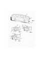
на фиг. 1 показана упрощенная наглядная иллюстрация кейджа для позвоночника в исходной сжатой конфигурации, сконструированного и действующего в соответствии с одним из неограничивающих вариантов осуществления изобретения;in FIG. 1 shows a simplified, illustrative illustration of a cage for the spine in an initial compressed configuration designed and operable in accordance with one non-limiting embodiment of the invention;
на фиг. 2 и 3 показаны, соответственно, упрощенные наглядные иллюстрации и виды с торца проиллюстрированного на фиг. 1 кейджа в раздвинутой конфигурации, в которой кейдж поднят на новую высоту и наклонен под новым углом (например, с целью достижения желаемой высоты и угла лордоза);in FIG. 2 and 3 show, respectively, simplified pictorial illustrations and end views of FIG. 1 cage in an extended configuration, in which the cage is raised to a new height and tilted at a new angle (for example, in order to achieve the desired height and angle of the lordosis);
на фиг. 4 показана упрощенная наглядная иллюстрация кейджа для позвоночника в исходной сжатой конфигурации, сконструированного и действующего в соответствии с другим неограничивающим вариантом осуществления изобретения;in FIG. 4 shows a simplified, pictorial illustration of a cage for a spine in an initial compressed configuration designed and operable in accordance with another non-limiting embodiment of the invention;
на фиг. 5, 6 и 7 показаны упрощенные виды с торца проиллюстрированного на фиг. 4 кейджа, в соответствующих сжатой, раздвинутой по высоте и раздвинутой по высоте с наклоном конфигурации;in FIG. 5, 6 and 7 are simplified end views of the illustrated in FIG. 4 cages, in the corresponding compressed, spread out on height and spread out on height with a tilt configuration;
на фиг. 8 и 9 показаны упрощенные наглядные иллюстрации и виды сбоку, соответственно, внутренних наклонных плоскостей в кейдже, которые определяют, как пластины наклоняются и перемещаются относительно друг друга; иin FIG. 8 and 9 show simplified pictorial illustrations and side views, respectively, of internal inclined planes in the cage, which determine how the plates are tilted and moved relative to each other; and
на фиг. 10 показана упрощенная наглядная иллюстрация установочного устройства и регулировочного устройства для установки кейджа для позвоночника, сконструированного и действующего в соответствии с одним из неограничивающих вариантом осуществления изобретения.in FIG. 10 is a simplified pictorial illustration of an installation device and adjusting device for installing a cage for a spine designed and operable in accordance with one non-limiting embodiment of the invention.
Подробное описание вариантов осуществленияDetailed Description of Embodiments
Рассмотрим фиг. 1-3, на которых проиллюстрирован кейдж 10 для позвоночника, сконструированный и действующий в соответствии с одним из неограничивающих вариантов осуществления изобретения.Consider FIG. 1-3, which illustrates a
Кейдж 10 для позвоночника содержит первую опорную пластину 12 и вторую опорную пластину 14, которые изначально могут (но необязательно, т.е. опционально) проходить параллельно друг другу. Первая опорная пластина 12 с возможностью поворота соединена со второй опорной пластиной 14 с помощью шарнира 16. Между первой и второй опорными пластинами 12 и 14 расположен движитель 18 пластин. Движителем 18 пластин может являться клин с наклонной поверхностью или другая применимая толкающая структура, которая может иметь плоскую или изогнутую форму (любую геометрическую форму). Движитель 18 пластин выполнен с возможностью скольжения по наклонной поверхности 20 (имеющей любую геометрическую форму) (например, с обратной стороны) первой опорной пластины 12. Как будет описано далее, при скольжении движителя 18 пластин по наклонной поверхности 20 первая опорная пластина 12 поднимается и/или наклоняется относительно второй опорной пластины 14.The
Различные по длине или ширине участки наклонной поверхности 20 (а также движителя 18 пластин) могут иметь различные наклоны (с точки зрения глубины, угла, длины, формы, размера и т.д.).The sections of the inclined surface 20 (as well as the plate mover 18), different in length or width, can have different slopes (in terms of depth, angle, length, shape, size, etc.).
Движитель 18 пластин может приводиться в действие с исполнительным механизмом 22, таким как линейный исполнительный механизм (например, регулировочным винтом, ввинченным во втулку, выступающую из второй опорной пластины 14). Исполнительный механизм 22 может приводиться в действие вручную (например, путем поворота соответствующей отвертки, который сопрягается с головкой регулировочного винта) или автоматически (например, исполнительным механизмом 22 может являться двигатель с местным или дистанционным управлением, который поворачивает регулировочный винт, например, с обратной связью от датчиков в контуре управления).The
Шарнир 16 установлен в удлиненном отверстии 24 (например, овальном или эллиптическом отверстии), выполненном в корпусе 26 шарнира, выступающем из первой опорной пластины 12. Шарнир 16 свободно перемещается и поворачивается в удлиненном отверстии 24.The
В соответствии с одним из неограничивающих вариантов осуществления настоящего изобретения в сторону шарнира 16 и/или первой опорной пластины 12 может быть смещен один или более опорных элементов 28. Опорные элементы 28 могут быть изготовлены из гибкого материала или могут поджиматься смещающим устройством 30 (например, листовой пружиной или спиральной пружиной). Изначально, когда кейдж 10 для позвоночника находится в сжатой конфигурации, опорные элементы 28 просто упираются в шарнир 16 и/или первую опорную пластину 12. После того, как первая опорная пластина 12 поднимается и/или наклоняется относительно второй опорной пластины 14, между шарниром 16 и второй опорной пластиной 14 и/или между первой опорной пластиной 12 и второй опорной пластиной 14 образуется зазор, и опорные элементы 28 пожимаются в этот зазор смещающим усилием. За счет этого опорные элементы 28 поддерживают и удерживают первую опорную пластину 12 в раздвинутой конфигурации (поднятой и/или наклоненной). Один или более опорных элементов 28 могут перемещаться поступательно и/или с поворотом (например, вокруг оси вращения).In accordance with one non-limiting embodiment of the present invention, one or
Рассмотрим фиг. 4-7, на которых проиллюстрирован кейдж 10 для позвоночника с одним или более килями 32, отходящими (например, под прямым углом) от первой опорной пластины 12 и/или второй опорной пластины 14. Кили 32 могут использоваться для обеспечения правильной ориентации кейджа в структуре позвоночника при его установке. На фиг. 5-7 проиллюстрирован кейдж 10 для позвоночника, соответственно, в сжатой, раздвинутой по высоте и раздвинутой по высоте с наклоном конфигурациях.Consider FIG. 4-7, illustrating a
Рассмотрим фиг. 8 и 9, на которых проиллюстрирована одна или несколько внутренних наклонных плоскостей 40 в кейдже 10, по которым движется первая опорная пластина 12 и которые определяют, как пластины 12 и 14 наклоняются и движутся относительно друг друга. Наклонные плоскости 40 служат наклонной поверхностью 20 или могут дополнять другую наклонную поверхность. Как видно из проиллюстрированного варианта осуществления, длина, высота, форма или угол наклонного участка одной из наклонных плоскостей могут отличаться от другой из наклонных плоскостей. Шарнир и первая опорная пластина могут скользить вверх по одной из наклонных плоскостей до достижения шарниром своего верхнего положения в удлиненном отверстии. Затем скольжение продолжается по другой наклонной плоскости или наклонным плоскостям, вызывая наклон первой опорной пластины. Таким образом, наклонные плоскости помогают достигать желаемого угла лордоза.Consider FIG. 8 and 9, which illustrate one or more internal
Рассмотрим фиг. 10, на которой показана упрощенная наглядная иллюстрация установочного устройства 42 и регулировочного устройства 44 для установки кейджа для позвоночника, сконструированного и действующего в соответствии с одним из неограничивающих вариантов осуществления изобретения.Consider FIG. 10, which shows a simplified pictorial illustration of an installation device 42 and an
Установочным устройством 42 может являться трубка с проксимальной воронкой 43. Регулировочным устройством 44 может являться, например, отвертка для поворота исполнительного механизма. Кейдж 10 может крепиться к дистальной части установочного устройства 42 (например, с помощью соединения типа "папа-мама", резьбового соединения или любого другого применимого соединения). Установочное устройство 42 захватывает кейдж 10 во время введения в междисковое пространство или другую структуру. Регулировочное устройство инструмент 44 может вводиться через трубку установочного устройства 42 с целью достижения исполнительного механизма. После того, как кейдж 10 раздвигается на месте, регулировочное устройство 44 удаляется. После подъема или наклона первой опорной пластины в кейдже, например, под первую опорную пластину может дополнительно вводиться костный трансплантат, коллаген или другие материалы.The installation device 42 may be a tube with a
Claims (11)
Translated fromRussianApplications Claiming Priority (1)
| Application Number | Priority Date | Filing Date | Title |
|---|---|---|---|
| PCT/IB2016/051800WO2017168208A1 (en) | 2016-03-30 | 2016-03-30 | Adjustable spinal cage |
Publications (1)
| Publication Number | Publication Date |
|---|---|
| RU2715750C1true RU2715750C1 (en) | 2020-03-03 |
Family
ID=55963414
Family Applications (1)
| Application Number | Title | Priority Date | Filing Date |
|---|---|---|---|
| RU2018138266ARU2715750C1 (en) | 2016-03-30 | 2016-03-30 | Adjustable cage for vertebral column |
Country Status (9)
| Country | Link |
|---|---|
| EP (1) | EP3435923B1 (en) |
| JP (1) | JP6894918B2 (en) |
| KR (2) | KR102591841B1 (en) |
| CN (1) | CN109152645B (en) |
| BR (1) | BR112018069074B1 (en) |
| CA (1) | CA3018624A1 (en) |
| ES (1) | ES2875599T3 (en) |
| RU (1) | RU2715750C1 (en) |
| WO (1) | WO2017168208A1 (en) |
Families Citing this family (22)
| Publication number | Priority date | Publication date | Assignee | Title |
|---|---|---|---|---|
| EP3755273B1 (en) | 2018-02-22 | 2025-04-30 | Warsaw Orthopedic, Inc. | Expandable spinal implant system |
| US11806250B2 (en) | 2018-02-22 | 2023-11-07 | Warsaw Orthopedic, Inc. | Expandable spinal implant system and method of using same |
| CN111655203A (en)* | 2018-02-22 | 2020-09-11 | 华沙整形外科股份有限公司 | Expandable spinal implant system and method of use |
| US12239544B2 (en) | 2020-11-05 | 2025-03-04 | Warsaw Orthopedic, Inc. | Rhomboid shaped implants |
| US12121453B2 (en) | 2020-11-05 | 2024-10-22 | Warsaw Orthopedic, Inc. | Dual wedge expandable implant with eyelets, system, and method of use |
| US11517363B2 (en) | 2020-11-05 | 2022-12-06 | Warsaw Orthopedic, Inc. | Screw driver and complimentary screws |
| US11638653B2 (en) | 2020-11-05 | 2023-05-02 | Warsaw Orthopedic, Inc. | Surgery instruments with a movable handle |
| US12318308B2 (en) | 2020-11-05 | 2025-06-03 | Warsaw Orthopedic, Inc. | Dual expandable inter-body device |
| US11963881B2 (en) | 2020-11-05 | 2024-04-23 | Warsaw Orthopedic, Inc. | Expandable inter-body device, system, and method |
| US11291554B1 (en) | 2021-05-03 | 2022-04-05 | Medtronic, Inc. | Unibody dual expanding interbody implant |
| US11517443B2 (en) | 2020-11-05 | 2022-12-06 | Warsaw Orthopedic, Inc. | Dual wedge expandable implant, system and method of use |
| US11376134B1 (en) | 2020-11-05 | 2022-07-05 | Warsaw Orthopedic, Inc. | Dual expanding spinal implant, system, and method of use |
| US11395743B1 (en) | 2021-05-04 | 2022-07-26 | Warsaw Orthopedic, Inc. | Externally driven expandable interbody and related methods |
| US12171439B2 (en) | 2020-11-05 | 2024-12-24 | Warsaw Orthopedic, Inc. | Protected drill |
| US11833059B2 (en) | 2020-11-05 | 2023-12-05 | Warsaw Orthopedic, Inc. | Expandable inter-body device, expandable plate system, and associated methods |
| US11285014B1 (en) | 2020-11-05 | 2022-03-29 | Warsaw Orthopedic, Inc. | Expandable inter-body device, system, and method |
| US11612499B2 (en) | 2021-06-24 | 2023-03-28 | Warsaw Orthopedic, Inc. | Expandable interbody implant |
| US12295865B2 (en) | 2021-06-24 | 2025-05-13 | Warsaw Orthopedic, Inc. | Expandable interbody implant and corresponding inserter |
| US12268614B2 (en) | 2021-06-24 | 2025-04-08 | Warsaw Orthopedic, Inc. | Interbody implant with adjusting shims |
| WO2022271280A1 (en) | 2021-06-24 | 2022-12-29 | Warsaw Orthopedic, Inc. | Expandable interbody implant and corresponding surgical tool |
| US11730608B2 (en) | 2021-07-13 | 2023-08-22 | Warsaw Orthopedic, Inc. | Monoblock expandable interbody implant |
| US11850163B2 (en) | 2022-02-01 | 2023-12-26 | Warsaw Orthopedic, Inc. | Interbody implant with adjusting shims |
Citations (7)
| Publication number | Priority date | Publication date | Assignee | Title |
|---|---|---|---|---|
| WO1998014142A1 (en)* | 1996-10-01 | 1998-04-09 | Surgical Dynamics, Inc. | Spinal fusion implant and method of insertion thereof |
| US20020143401A1 (en)* | 2001-03-27 | 2002-10-03 | Michelson Gary K. | Radially expanding interbody spinal fusion implants, instrumentation, and methods of insertion |
| US20050065611A1 (en)* | 2001-11-06 | 2005-03-24 | Jean Huppert | Osseous achoring device for a prosthesis |
| US20080140207A1 (en)* | 2006-12-07 | 2008-06-12 | Interventional Spine, Inc. | Intervertebral implant |
| US20110172774A1 (en)* | 2010-01-11 | 2011-07-14 | Armando Varela | Expandable intervertebral implant and associated surgical method |
| RU2465870C1 (en)* | 2011-02-28 | 2012-11-10 | Общество с ограниченной ответственностью "Эндокарбон" | Intervertebral disc prosthesis |
| US20160030190A1 (en)* | 2012-08-08 | 2016-02-04 | James C. Robinson | Expandable intervertebral cage assemblies |
Family Cites Families (13)
| Publication number | Priority date | Publication date | Assignee | Title |
|---|---|---|---|---|
| CA1283501C (en)* | 1987-02-12 | 1991-04-30 | Thomas P. Hedman | Artificial spinal disc |
| US6641614B1 (en)* | 1997-05-01 | 2003-11-04 | Spinal Concepts, Inc. | Multi-variable-height fusion device |
| DE19807236C2 (en)* | 1998-02-20 | 2000-06-21 | Biedermann Motech Gmbh | Intervertebral implant |
| US20040087947A1 (en)* | 2002-08-28 | 2004-05-06 | Roy Lim | Minimally invasive expanding spacer and method |
| CN200970284Y (en)* | 2006-02-28 | 2007-11-07 | 赵定麟 | Marmem cervical vertebra artificial intervertebral disc |
| US8057547B2 (en)* | 2007-06-12 | 2011-11-15 | Kinetic Spine Technologies Inc. | Articulating intervertebral disc prosthesis |
| ES2564289T3 (en)* | 2010-10-26 | 2016-03-21 | Christian Röbling | Intervertebral disc prosthesis |
| EP2729092B1 (en)* | 2011-08-16 | 2016-09-21 | Stryker European Holdings I, LLC | Expandable implant |
| US9445919B2 (en)* | 2011-12-19 | 2016-09-20 | Warsaw Orthopedic, Inc. | Expandable interbody implant and methods of use |
| EP2742914A1 (en)* | 2012-12-14 | 2014-06-18 | FACET-LINK Inc. | Infinitely height-adjustable vertebral fusion implant |
| JP6343820B2 (en)* | 2013-03-15 | 2018-06-20 | スペクトラム スパイン アイピー ホールディングス, エルエルシー | Expandable interbody fusion device and method |
| US9980825B2 (en)* | 2013-05-13 | 2018-05-29 | Biospine, Llc | Adjustable interbody fusion devices |
| US9427331B2 (en)* | 2014-07-15 | 2016-08-30 | Apifix Ltd. | Spinal cage |
- 2016
- 2016-03-30RURU2018138266Apatent/RU2715750C1/enactive
- 2016-03-30ESES16721937Tpatent/ES2875599T3/enactiveActive
- 2016-03-30WOPCT/IB2016/051800patent/WO2017168208A1/ennot_activeCeased
- 2016-03-30KRKR1020187027986Apatent/KR102591841B1/enactiveActive
- 2016-03-30CNCN201680084171.4Apatent/CN109152645B/ennot_activeExpired - Fee Related
- 2016-03-30EPEP16721937.7Apatent/EP3435923B1/enactiveActive
- 2016-03-30CACA3018624Apatent/CA3018624A1/enactivePending
- 2016-03-30JPJP2018549547Apatent/JP6894918B2/ennot_activeExpired - Fee Related
- 2016-03-30KRKR1020237035402Apatent/KR20230148397A/ennot_activeCeased
- 2016-03-30BRBR112018069074-0Apatent/BR112018069074B1/ennot_activeIP Right Cessation
Patent Citations (7)
| Publication number | Priority date | Publication date | Assignee | Title |
|---|---|---|---|---|
| WO1998014142A1 (en)* | 1996-10-01 | 1998-04-09 | Surgical Dynamics, Inc. | Spinal fusion implant and method of insertion thereof |
| US20020143401A1 (en)* | 2001-03-27 | 2002-10-03 | Michelson Gary K. | Radially expanding interbody spinal fusion implants, instrumentation, and methods of insertion |
| US20050065611A1 (en)* | 2001-11-06 | 2005-03-24 | Jean Huppert | Osseous achoring device for a prosthesis |
| US20080140207A1 (en)* | 2006-12-07 | 2008-06-12 | Interventional Spine, Inc. | Intervertebral implant |
| US20110172774A1 (en)* | 2010-01-11 | 2011-07-14 | Armando Varela | Expandable intervertebral implant and associated surgical method |
| RU2465870C1 (en)* | 2011-02-28 | 2012-11-10 | Общество с ограниченной ответственностью "Эндокарбон" | Intervertebral disc prosthesis |
| US20160030190A1 (en)* | 2012-08-08 | 2016-02-04 | James C. Robinson | Expandable intervertebral cage assemblies |
Also Published As
| Publication number | Publication date |
|---|---|
| WO2017168208A1 (en) | 2017-10-05 |
| KR20230148397A (en) | 2023-10-24 |
| EP3435923A1 (en) | 2019-02-06 |
| CN109152645B (en) | 2021-05-07 |
| ES2875599T3 (en) | 2021-11-10 |
| BR112018069074B1 (en) | 2023-04-18 |
| CN109152645A (en) | 2019-01-04 |
| CA3018624A1 (en) | 2017-10-05 |
| EP3435923B1 (en) | 2021-04-28 |
| BR112018069074A2 (en) | 2019-01-29 |
| KR20190022450A (en) | 2019-03-06 |
| JP2019509829A (en) | 2019-04-11 |
| KR102591841B1 (en) | 2023-10-20 |
| JP6894918B2 (en) | 2021-06-30 |
Similar Documents
| Publication | Publication Date | Title |
|---|---|---|
| RU2715750C1 (en) | Adjustable cage for vertebral column | |
| US9827107B1 (en) | Adjustable spinal cage | |
| US10426633B2 (en) | Zero-profile expandable intervertebral spacer devices for distraction and spinal fusion and a universal tool for their placement and expansion | |
| US9233007B2 (en) | Expandable self-anchoring interbody cage for orthopedic applications | |
| EP3035893B1 (en) | Interbody fusion devices with self-affixing mechanisms | |
| DK2224867T3 (en) | Spinal WITH A POST-OPERATIVE ADJUSTABLE DIMENSION | |
| JP2021517015A (en) | Intervertebral cage with integrated dilation and angle adjustment mechanism | |
| US6945973B2 (en) | Slidable bone plate system | |
| US20100241174A1 (en) | Bone screw retaining and removal system | |
| JP2014505522A (en) | Spine implant device and method of implanting and using the same | |
| US20150190184A1 (en) | Bone screw retaining system | |
| JP7270659B2 (en) | adjustable spine cage | |
| US8870932B2 (en) | Bone screw retaining system with pinned retainer | |
| RU2322212C1 (en) | Instrument set for implantation of implant of intervertebral joint | |
| US11039937B2 (en) | Expansion apparatus | |
| KR101085463B1 (en) | Cage with adjustable contact angle | |
| WO2013067454A1 (en) | Bone screw retaining system with pinned retainer |