RU2713548C2 - Drilling rod or adapter with reinforced connecting element in form of bushing - Google Patents
Drilling rod or adapter with reinforced connecting element in form of bushingDownload PDFInfo
- Publication number
- RU2713548C2 RU2713548C2RU2017144031ARU2017144031ARU2713548C2RU 2713548 C2RU2713548 C2RU 2713548C2RU 2017144031 ARU2017144031 ARU 2017144031ARU 2017144031 ARU2017144031 ARU 2017144031ARU 2713548 C2RU2713548 C2RU 2713548C2
- Authority
- RU
- Russia
- Prior art keywords
- curvature
- thread
- component according
- transition zone
- component
- Prior art date
Links
- 238000005553drillingMethods0.000titleclaimsabstractdescription16
- 230000004323axial lengthEffects0.000claimsabstractdescription20
- 230000007704transitionEffects0.000claimsdescription36
- 238000009527percussionMethods0.000claimsdescription3
- 239000011435rockSubstances0.000abstractdescription5
- 238000005065miningMethods0.000abstract1
- 239000002689soilSubstances0.000abstract1
- 239000000126substanceSubstances0.000abstract1
- 238000005452bendingMethods0.000description12
- 230000035939shockEffects0.000description8
- 230000005540biological transmissionEffects0.000description6
- 230000007423decreaseEffects0.000description4
- 238000011010flushing procedureMethods0.000description2
- 238000004804windingMethods0.000description2
- 230000009471actionEffects0.000description1
- 230000008859changeEffects0.000description1
- 230000006378damageEffects0.000description1
- 239000012530fluidSubstances0.000description1
- 230000007246mechanismEffects0.000description1
- 238000000034methodMethods0.000description1
- 230000009467reductionEffects0.000description1
- 238000000926separation methodMethods0.000description1
- 210000000323shoulder jointAnatomy0.000description1
Images


Classifications
- E—FIXED CONSTRUCTIONS
- E21—EARTH OR ROCK DRILLING; MINING
- E21B—EARTH OR ROCK DRILLING; OBTAINING OIL, GAS, WATER, SOLUBLE OR MELTABLE MATERIALS OR A SLURRY OF MINERALS FROM WELLS
- E21B17/00—Drilling rods or pipes; Flexible drill strings; Kellies; Drill collars; Sucker rods; Cables; Casings; Tubings
- E21B17/02—Couplings; joints
- E21B17/04—Couplings; joints between rod or the like and bit or between rod and rod or the like
- E21B17/042—Threaded
- E—FIXED CONSTRUCTIONS
- E21—EARTH OR ROCK DRILLING; MINING
- E21B—EARTH OR ROCK DRILLING; OBTAINING OIL, GAS, WATER, SOLUBLE OR MELTABLE MATERIALS OR A SLURRY OF MINERALS FROM WELLS
- E21B1/00—Percussion drilling
- E21B1/38—Hammer piston type, i.e. in which the tool bit or anvil is hit by an impulse member
- E—FIXED CONSTRUCTIONS
- E21—EARTH OR ROCK DRILLING; MINING
- E21B—EARTH OR ROCK DRILLING; OBTAINING OIL, GAS, WATER, SOLUBLE OR MELTABLE MATERIALS OR A SLURRY OF MINERALS FROM WELLS
- E21B17/00—Drilling rods or pipes; Flexible drill strings; Kellies; Drill collars; Sucker rods; Cables; Casings; Tubings
- E21B17/02—Couplings; joints
- E21B17/04—Couplings; joints between rod or the like and bit or between rod and rod or the like
- E21B17/042—Threaded
- E21B17/0426—Threaded with a threaded cylindrical portion, e.g. for percussion rods
- F—MECHANICAL ENGINEERING; LIGHTING; HEATING; WEAPONS; BLASTING
- F16—ENGINEERING ELEMENTS AND UNITS; GENERAL MEASURES FOR PRODUCING AND MAINTAINING EFFECTIVE FUNCTIONING OF MACHINES OR INSTALLATIONS; THERMAL INSULATION IN GENERAL
- F16L—PIPES; JOINTS OR FITTINGS FOR PIPES; SUPPORTS FOR PIPES, CABLES OR PROTECTIVE TUBING; MEANS FOR THERMAL INSULATION IN GENERAL
- F16L15/00—Screw-threaded joints; Forms of screw-threads for such joints
- F16L15/06—Screw-threaded joints; Forms of screw-threads for such joints characterised by the shape of the screw-thread
Landscapes
- Engineering & Computer Science (AREA)
- Geology (AREA)
- Life Sciences & Earth Sciences (AREA)
- Mining & Mineral Resources (AREA)
- Mechanical Engineering (AREA)
- Physics & Mathematics (AREA)
- Environmental & Geological Engineering (AREA)
- Fluid Mechanics (AREA)
- General Life Sciences & Earth Sciences (AREA)
- Geochemistry & Mineralogy (AREA)
- General Engineering & Computer Science (AREA)
- Earth Drilling (AREA)
- Drilling Tools (AREA)
Abstract
Description
Translated fromRussianОБЛАСТЬ ТЕХНИКИ ИЗОБРЕТЕНИЯFIELD OF THE INVENTION
Настоящее изобретение относится к компоненту бурильной колонны для образования части бурильной колонны, имеющему конец в виде соединительного элемента в виде втулки с резьбовой частью, выполненной с возможностью минимизации напряжения в зоне резьбы и вероятности выхода из строя соединения.The present invention relates to a drill string component for forming part of a drill string having an end in the form of a connecting element in the form of a sleeve with a threaded part, configured to minimize stress in the thread area and the likelihood of a joint failure.
Предшествующий уровень техникиState of the art
Ударное бурение применяетcя для создания длинного ствола скважины с помощью множества удлиненных штанг бурильной колонны, соединенных вместе торец к торцу с помощью соединения друг с другом охватываемых и охватывающих резьбовых концов. В общепринятой методике горную породу разрушают, производя удары, передаваемые с бурового долота для горной породы, установленного на одном конце бурильной колонны, на горную породу на забое ствола скважины. Обычно энергия, требуемая для разрушения горной породы, создается поршнем с гидравлическим приводом, который контактирует с концом бурильной колонны (через хвостовой переходник) для создания волны механического напряжения (или ударной волны), которая проходит по бурильной колонне и, в конце концов, на уровень основной породы. Обычные соединения с охватываемой и охватывающей резьбой описаны в документах EP 2845993, EP 1259703, EP 1232321 и US 4,968,068.Impact drilling is used to create a long wellbore using a plurality of elongated drill string, connected end-to-end together by connecting male and female threaded ends to each other. In the generally accepted methodology, the rock is destroyed by impacts transmitted from the drill bit for the rock installed at one end of the drill string to the rock at the bottom of the wellbore. Typically, the energy required to destroy the rock is generated by a hydraulic actuated piston that contacts the end of the drill string (through the tail adapter) to create a stress wave (or shock wave) that travels through the drill string and finally to the level main breed. Typical male and female connections are described in EP 2845993, EP 1259703, EP 1232321 and US 4,968,068.
Когда охватываемый и охватывающий резьбовые концы соседних штанг соединены для создания бурильной колонны, во время бурения соединительный узел обычно подвергается изгибающим усилиям. При этом изгибающие моменты вызывают усталость соединения и приводят к разрушению в резьбовом участке соединительного узла. Обычно повреждается резьбовая охватываемая втулка, которая и определяет эксплуатационный ресурс соединения. В частности, механические напряжения в резьбовой части охватываемой втулки, обычно являются значительными, и обычным для втулки является выход из строя в зоне резьбы. Дополнительно, механические напряжения в зоне резьбы возникают также вследствие передачи сжимающей ударной волны. Соответственно, требуется создание упрочненного охватываемого резьбового соединительного элемента, в котором решены указанные выше проблемы.When the male and female threaded ends of adjacent rods are connected to form a drill string, the joint is typically subjected to bending forces during drilling. In this case, bending moments cause fatigue of the connection and lead to destruction in the threaded section of the connecting node. Usually, the threaded male sleeve is damaged, which determines the service life of the connection. In particular, the mechanical stresses in the threaded portion of the male sleeve are usually significant, and failure in the thread area is common for the sleeve. Additionally, mechanical stresses in the thread area also occur due to transmission of a compressive shock wave. Accordingly, it is required to create a hardened male threaded connecting element in which the above problems are solved.
Сущность изобретенияSUMMARY OF THE INVENTION
Задачей настоящего изобретения является обеспечение компонента бурильной колонны для образования части бурильной колонны с охватываемым концом, выполненной с возможностью выдерживать силы несимметричной нагрузки, действующие на бурильную колонну, для уменьшения напряжения резьбовой части охватываемого конца и минимизации риска выхода из строя соединительного элемента. Дополнительной задачей является обеспечение соединительного элемента, стойкого к изгибным волнам в бурильной колонне, являющимся результатом, например отклонения скважины или внецентренных ударов приводного поршня на самой задней бурильной штанге или хвостовом переходнике. Дополнительной задачей является обеспечение бурильного компонента для соединения, предусматривающего контакт на заплечике, имеющего охватываемый резьбовой конец, который обеспечивает прочное соединение с соответствующим охватывающим резьбовым концом соседней бурильной штанги или с другим компонентом бурильной колонны для образования интегрального и прочного блока в собранной бурильной колонне.An object of the present invention is to provide a drill string component for forming a part of a drill string with a male end configured to withstand unbalanced load forces acting on the drill string to reduce the stress of the threaded part of the male end and minimize the risk of failure of the connecting element. An additional objective is to provide a bending wave resistant joint in the drill string resulting from, for example, deviation of the borehole or eccentric impacts of the drive piston at the rearmost drill stem or tail adapter. An additional object is to provide a boring component for a shoulder joint having a male threaded end that is firmly connected to the corresponding female threaded end of an adjacent drill rod or to another component of the drill string to form an integral and strong block in the assembled drill string.
Задачи решают, обеспечивая охватываемый соединительный элемент на бурильном компоненте с зоной контакта с заплечиком, в котором аксиальная длина не имеющей резьбы части хвостовика соединительного элемента в виде охватываемой втулки имеет заданную минимальную величину, связанную с наружным диаметром охватываемой втулки на резьбовой части.The problems are solved by providing a male connector on the drilling component with a shoulder contact area, in which the axial length of the threaded portion of the shank of the connector in the form of a male sleeve has a predetermined minimum value associated with the outer diameter of the male sleeve on the threaded part.
Согласно первому аспекту настоящего изобретения обеспечен удлиненный компонент для образования части бурильной колонны, содержащий: вытянутую секцию отрезка длины с парой аксиальных концов; охватываемую втулку, обеспеченную по меньшей мере на одном из концов и имеющую часть с наружной резьбой и не имеющий резьбы хвостовик, расположенный аксиально между резьбовой частью и секцией отрезка длины; причем охватываемая втулка, выступает аксиально от кольцевой боковой поверхности секции отрезка длины или проходящего радиально наружу заплечика, причем резьбовая часть имеет наружный диаметр (Dy), соответствующий вершине резьбы, и не имеющий резьбы хвостовик имеет аксиальную длину (Ls), определенную между аксиально внутренним концом резьбовой части и боковой поверхностью; отличающийся тем, что: отношение Ls/Dy равно или больше 0,4.According to a first aspect of the present invention, there is provided an elongated component for forming part of a drill string, comprising: an elongated section of a length section with a pair of axial ends; a male sleeve provided at least at one end and having a part with an external thread and a threadless shank located axially between the threaded part and the length section; moreover, the male sleeve protrudes axially from the annular lateral surface of the section of the length segment or the shoulder extending radially outward, the threaded part having an outer diameter (Dy) corresponding to the top of the thread, and the threadless shaft has an axial length (Ls) defined between the axially inner end threaded part and side surface; characterized in that: the ratio Ls / Dy is equal to or greater than 0.4.
В данном описании ссылка на Dy соответствует диаметральному расстоянию между радиальными позициями на вершинах (винтового гребня) на диаметрально противоположных сторонах резьбовой части для представления максимального диаметра резьбовой части. В случае, если резьбовая часть является, в общем, конической, Dy соответствует диаметральному расстоянию для аксиально крайней вершины, имеющей самый большой радиус/диаметр.In this description, the reference to Dy corresponds to the diametrical distance between the radial positions on the peaks (screw flange) on the diametrically opposite sides of the threaded part to represent the maximum diameter of the threaded part. In case the threaded portion is generally conical, Dy corresponds to the diametrical distance for the axially extreme peak having the largest radius / diameter.
В данном описании ссылка на Ds соответствует минимальному (наименьшему) диаметру не имеющего резьбы хвостовика, и Dm соответствует диаметру секции основного отрезка длины. Дополнительно, в данном описании, ссылка на Di соответствует диаметральному расстоянию между радиальными позициями на впадинах (винтового гребня) на диаметрально противоположных сторонах резьбовой части для представления минимального диаметра резьбовой части. В случае, если резьбовая часть является, в общем, конической, Di соответствует диаметральному расстоянию для аксиально крайней впадины профиля, имеющей самый большой радиус/диаметр.In this description, the reference to Ds corresponds to the minimum (smallest) diameter of the threadless shank, and Dm corresponds to the diameter of the section of the main length section. Additionally, in this description, the reference to Di corresponds to the diametrical distance between the radial positions on the troughs (screw flange) on the diametrically opposite sides of the threaded part to represent the minimum diameter of the threaded part. In case the threaded portion is generally conical, Di corresponds to the diametrical distance for the axially extreme cavity of the profile having the largest radius / diameter.
В описании ссылка на Ls соответствует аксиальной длине не имеющего резьбы хвостовика, определенной между аксиально внутренним концом резьбовой части и боковой поверхностью секции основного отрезка длины, и Lt соответствует аксиальной длине резьбовой части между концами выхода резьбы.In the description, the reference to Ls corresponds to the axial length of the threadless shank defined between the axially inner end of the threaded part and the side surface of the section of the main length section, and Lt corresponds to the axial length of the threaded part between the ends of the thread outlet.
Отношение Ls/Dy может иметь величину в диапазоне 0,4-1,0. Отношение Ls/Dy может иметь величину в диапазоне 0,45-1,0, 0,5-1,0, 0,55-1,0, 0,6-1,0, 0,65-1,0, 0,7-1,0, 0,75-1,0; 0,8-1,0 или 0,85-1,0. Предпочтительно, отношение Ls/Dy имеет величину в диапазоне 0,4-0,8 или 0,5-0,8. Отношение Ls/Dy может быть равно или больше 0,45, 0,5, 0,6 или 0,7. Аксиальное отделение винтовой резьбы от зоны контакта заплечика компонента бурильной колонны посредством данной минимальной аксиальной длины не имеющего резьбы хвостовика минимизирует абсолютную величину изгибающих сил, передаваемых через винтовую резьбу в результате боковых отклонений в положении бурового долота во время бурения или потенциально неидеальных ударов ударника. Соответственно, эксплуатационный ресурс бурильного компонента улучшен в сравнении с обычными охватываемыми соединительными элементами в дополнение к уменьшению риска выхода из строя соединительного элемента на забое скважины.The ratio Ls / Dy may have a value in the range of 0.4-1.0. The ratio Ls / Dy can have a value in the range of 0.45-1.0, 0.5-1.0, 0.55-1.0, 0.6-1.0, 0.65-1.0, 0 7-1.0; 0.75-1.0; 0.8-1.0 or 0.85-1.0. Preferably, the ratio Ls / Dy has a value in the range of 0.4-0.8 or 0.5-0.8. The ratio Ls / Dy may be equal to or greater than 0.45, 0.5, 0.6, or 0.7. The axial separation of the screw thread from the shoulder area of the drill string component by means of this minimum axial length of the threadless shank minimizes the absolute value of the bending forces transmitted through the screw thread as a result of lateral deviations in the position of the drill bit during drilling or potentially imperfect hammer drills. Accordingly, the operating life of the drilling component is improved in comparison with conventional male connecting elements in addition to reducing the risk of failure of the connecting element at the bottom of the well.
Предпочтительно, втулка имеет аксиальную длину (L) между аксиально крайней поверхностью втулки, и боковой поверхностью секции отрезка длины или заплечика, при этом отношение Ls/L равно или больше 0,25. Более предпочтительно, отношение Ls/L имеет величину в диапазоне 0,25-0,5; 0,3-0,5; 0,35-0,5; 0,4-0,5; 0,45-0,5. Благодаря максимизации аксиальной длины не имеющего резьбы хвостовика относительно общей аксиальной длины втулки, резьбовая часть аксиально отделена от зоны контакта заплечика компонента и, таким образом, выполнена с возможностью лучше выдерживать изгибающие моменты и, соответственно, уменьшать концентрации напряжения на винтовой резьбе. В данном описании аксиально внутренний конец резьбовой части определен, как аксиальное положение, на котором радиальное положение вершины или впадины профиля резьбы соответствует радиальному положению наружной поверхности не имеющего резьбы хвостовика.Preferably, the sleeve has an axial length (L) between the axially extreme surface of the sleeve and the side surface of the section of the length segment or shoulder, the ratio Ls / L is equal to or greater than 0.25. More preferably, the Ls / L ratio has a value in the range of 0.25-0.5; 0.3-0.5; 0.35-0.5; 0.4-0.5; 0.45-0.5. By maximizing the axial length of the threadless shank with respect to the total axial length of the sleeve, the threaded portion is axially separated from the contact zone of the shoulder of the component and is thus able to better withstand bending moments and, accordingly, reduce stress concentration on the screw thread. In this description, the axially inner end of the threaded portion is defined as the axial position at which the radial position of the top or bottom of the thread profile corresponds to the radial position of the outer surface of the non-threaded shank.
Для дополнительного улучшения стойкости к напряжению, являющемуся результатом изгибающих сил, хвостовик может содержать переходную зону, расположенную смежно с кольцевой боковой поверхностью, при этом профиль сечения на переходной зоне в плоскости, проходящей через продольную ось компонента, является криволинейным, при этом площадь сечения хвостовика увеличивается аксиально к кольцевой боковой поверхности. Более предпочтительно, кривизна переходной зоны аксиально самой близкой к боковой поверхности содержит первый радиус кривизны, который меньше второго радиуса кривизны наружной поверхности на переходной зоне аксиально самой близкой к резьбовой части, причем наружный диаметр переходной зоны по первому и второму радиусам кривизны увеличивается в направлении от резьбовой части до боковой поверхности. Соответственно, аксиальный стык между зоной заплечика компонента и концом трубы, (и в частности не имеющим резьбы хвостовиком) усилен для сопротивления изгибающим моментам для уменьшения концентрации напряжения и риска выхода из строя соединения под нагрузкой. Ссылка на 'кривизну' означает плавное или постепенное изменение профиля поверхности, а также множество последовательных линейных увеличений в диаметре от не имеющего резьбы хвостовика до заплечика, которые вместе можно рассматривать, как профиль 'криволинейной' формы.To further improve the resistance to stress resulting from bending forces, the shank may contain a transition zone located adjacent to the annular side surface, while the cross-sectional profile on the transition zone in the plane passing through the longitudinal axis of the component is curved, while the cross-sectional area of the shank increases axially to the annular lateral surface. More preferably, the curvature of the transition zone axially closest to the side surface contains a first radius of curvature that is smaller than the second radius of curvature of the outer surface on the transition zone axially closest to the threaded portion, the outer diameter of the transition zone along the first and second radii of curvature increasing in the direction from the threaded parts to the side surface. Accordingly, the axial junction between the shoulder region of the component and the end of the pipe (and in particular the threadless shank) is reinforced to resist bending moments to reduce stress concentration and the risk of failure of the joint under load. The reference to 'curvature' means a smooth or gradual change in the surface profile, as well as many consecutive linear increases in diameter from a threadless shank to the shoulder, which together can be considered as a profile of a 'curved' shape.
Компонент бурильной колонны может содержать заплечик, выступающий радиально от секции основного отрезка длины или секции общего отрезка длины компонента так, что наружный диаметр заплечика больше наружного диаметра секции отрезка длины и/или охватываемой втулки. Если необходимо, заплечик и, в частности, кольцевая боковая поверхность могут быть образованы аксиальным концом секции отрезка длины компонента или аксиальной стороной радиально проходящего заплечика. Такая конфигурация обеспечивает соединение с контактом на заплечике, между охватываемой втулкой, и соответствующей охватывающей муфтой. Если необходимо, профиль сечения наружной поверхности переходной зоны между не имеющим резьбы хвостовиком и кольцевой концевой поверхностью в плоскости продольной ось компонента содержит сегмент в форме эллипса. Если необходимо, сегмент составляет, по существу, одну четверть периметра эллипса.The drill string component may comprise a shoulder extending radially from a section of the main length section or a section of a common length section of the component so that the outer diameter of the shoulder is larger than the outer diameter of the section of the length section and / or the male sleeve. If necessary, the shoulder and, in particular, the annular side surface can be formed by the axial end of the section of the length of the component or the axial side of the radially extending shoulder. This configuration provides a connection with a contact on the shoulder, between the male sleeve, and the corresponding female sleeve. If necessary, the cross-sectional profile of the outer surface of the transition zone between the non-threaded shank and the annular end surface in the plane of the longitudinal axis of the component contains a segment in the form of an ellipse. If necessary, the segment is essentially one quarter of the perimeter of the ellipse.
В данном описании ссылка на Ds соответствует минимальному (наименьшему) диаметру не имеющего резьбы хвостовика, и Dm соответствует диаметру секции основного отрезка длины.In this description, the reference to Ds corresponds to the minimum (smallest) diameter of the threadless shank, and Dm corresponds to the diameter of the section of the main length section.
Предпочтительно, Ls меньше аксиальной длины Lt резьбовой части. Если необходимо, диаметр (Ds) не имеющего резьбы хвостовика приблизительно равен или меньше диаметра (Dm) секции основного отрезка длины. Если необходимо, Ds может быть приблизительно равен Dy.Preferably, Ls is less than the axial length Lt of the threaded portion. If necessary, the diameter (Ds) of the non-threaded shank is approximately equal to or less than the diameter (Dm) of the section of the main length section. If necessary, Ds may be approximately equal to Dy.
Предпочтительно, Ds меньше Dy. Предпочтительно, Ds меньше диаметрального расстояния (Di) между радиальными позициями впадин (между винтовыми гребнями) на диаметрально противоположных сторонах резьбовой части. Более предпочтительно, Ds может иметь величину в диапазоне от (Di минус Td) до (Di минус 4Td), где Td глубина резьбы перпендикулярно продольной оси между радиальными позициями вершины и впадины профиля. Более предпочтительно, Ds имеет величину в диапазоне от (Di минус Td) до (Di минус 3Td). Наиболее предпочтительно, Ds равно Di минус 2Td. Втулка, содержащая конфигурацию Ds, подробно описанную в данном документе, является предпочтительной для обеспечения оптимизации переходной зоны смежной с кольцевой боковой поверхностью заплечика или концом секции основного отрезка длины. В частности, Ds меньший Di обеспечивает аксиально более длинную переходную зону и большие радиусы кривизны на переходе между не имеющим резьбы хвостовиком и кольцевой боковой поверхностью (заплечика или секции основного отрезка длины). Соответственно, представленная конфигурация Ds минимизирует концентрации напряжения на основании втулки, (на ее стыке с секцией основного отрезка длины или заплечиком). Представленная конфигурация Ds в комбинации с Ls является, соответственно, предпочтительной для обеспечения ударного компонента, который является стойким к напряжениям изгиба и также выполнен с возможностью выдерживать механические напряжения, являющиеся результатом передачи ударной волны через втулку, когда компоненты бурильной колонны являются совершенно соосными, а также когда отклонены (немного не соосны относительно друг друга) при применении.Preferably, Ds is less than Dy. Preferably, Ds is less than the diametrical distance (Di) between the radial positions of the depressions (between the screw ridges) on the diametrically opposite sides of the threaded portion. More preferably, Ds may have a value in the range of (Di minus Td) to (Di minus 4Td), where Td is the thread depth perpendicular to the longitudinal axis between the radial positions of the top and bottom of the profile. More preferably, Ds has a value in the range of (Di minus Td) to (Di minus 3Td). Most preferably, Ds is Di minus 2Td. A sleeve containing the Ds configuration described in detail herein is preferred for optimizing the transition zone adjacent to the annular lateral surface of the shoulder or the end of the section of the main length section. In particular, Ds smaller Di provides an axially longer transition zone and large radii of curvature at the transition between a threaded shank and an annular lateral surface (shoulder or section of the main length section). Accordingly, the presented configuration Ds minimizes stress concentration at the base of the sleeve, (at its junction with the section of the main length segment or shoulder). The presented configuration Ds in combination with Ls is accordingly preferable for providing a shock component that is resistant to bending stresses and also configured to withstand mechanical stresses resulting from the transmission of the shock wave through the sleeve when the components of the drill string are perfectly coaxial, and when rejected (slightly out of alignment with respect to each other) during use.
Предпочтительно, кривизна переходной зоны аксиально самой близкой к боковой поверхности содержит по меньшей мере три или четыре радиуса кривизны. Если необходимо, кривизна переходной зоны содержит от трех до шести или от трех до четырех радиусов кривизны. Предпочтительно, радиусы на переходной зоне увеличиваются в аксиальном направлении от боковой поверхности (заплечика или основного отрезка длины) к минимальному диаметру (Ds) не имеющего резьбы хвостовика. Предпочтительно, переходная зона содержит три или четыре отличающихся радиуса кривизны. Первый радиус R1 кривизны может составлять приблизительно половину второго радиуса R1 кривизны ≈ R2/2; R2 может составлять приблизительно половину третьего радиуса R2 кривизны ≈ R3/2; R3 может составлять приблизительно треть четвертого радиуса R3 кривизны ≈ R4/3, соответственно, на переходной зоне, где R1 расположен ближе всего к боковой поверхности, и R4 расположен на минимальном диаметре Ds не имеющего резьбы хвостовика и образует его.Preferably, the curvature of the transition zone axially closest to the side surface contains at least three or four radii of curvature. If necessary, the curvature of the transition zone contains from three to six or from three to four radii of curvature. Preferably, the radii at the transition zone increase in the axial direction from the lateral surface (shoulder or main length) to the minimum diameter (Ds) of the non-threaded shank. Preferably, the transition zone comprises three or four distinct radii of curvature. The first radius of curvature R1 may be approximately half the second radius of curvature R1 ≈ R2 / 2; R2 may be approximately half the third radius R2 of curvature ≈ R3 / 2; R3 can be approximately one third of the fourth radius R3 of curvature ≈ R4 / 3, respectively, in the transition zone, where R1 is located closest to the side surface, and R4 is located on the minimum diameter Ds of a threadless thread and forms it.
Связанное изобретение сконфигурировано, конкретно, как резьбовая втулка для компонента ударного бурения. Удлиненный компонент и, в частности, охватываемая втулка посредством конфигурации резьбы и не имеющего резьбы хвостовика (подробно описаны в данном документе) выполнены с возможностью выдерживать силы изгиба и концентрации напряжения, являющиеся результатом передачи ударов, с минимизацией любого уменьшения абсолютной величины ударной волны во время передачи. Профиль резьбы втулки приспособлен для ударного бурения, и, предпочтительно, резьба содержит неизменный диаметр вдоль аксиальный длины Lt резьбовой части. То есть, резьбовая часть выполнена, предпочтительно, как, в общем, цилиндрическая часть. При этом профиль резьбы считается достаточно прочным, чтобы выдерживать передачу ударной волны и, таким образом, силы от высокой нагрузки. В частности, связанное изобретение содержит резьбу, имеющую шаг с величиной в диапазоне от 5 до 50 мм для бурильных компонентов с увеличением соответствующих наружных диаметров. Дополнительно, шаговый угол резьбы связанного изобретения может иметь величину в диапазоне 5-10° для компонента с соответствующим шагом и наружным диаметром, где шаговый угол является углом θ между траекторией винтовой резьбы и касательной перпендикулярной продольной оси удлиненного компонента. Дополнительно, диаметр Dy резьбовой части (расстояние от вершины до вершины резьбы) согласно аспектам настоящего изобретения может иметь величину в диапазоне 15-120 мм для соответствующих величин шага и шаговых углов. Соответственно, связанное изобретение может содержать конфигурацию резьбы в которой отношение шаг/диаметр резьбы имеет величину в диапазоне 0,3-0,6; 0,35-0,55 и, если необходимо, 0,4-0,46.The related invention is configured specifically as a threaded sleeve for an impact drilling component. The elongated component and, in particular, the male sleeve by means of a thread configuration and a threadless shank (described in detail herein) are configured to withstand bending forces and stress concentrations resulting from shock transmission, while minimizing any reduction in the absolute value of the shock wave during transmission . The thread profile of the sleeve is adapted for percussion drilling, and preferably, the thread contains a constant diameter along the axial length Lt of the threaded portion. That is, the threaded portion is preferably made as a generally cylindrical portion. In this case, the thread profile is considered strong enough to withstand the transmission of the shock wave and, thus, the forces from high load. In particular, the related invention comprises a thread having a pitch with a value in the range of 5 to 50 mm for the drill components with an increase in the respective outer diameters. Additionally, the pitch angle of the thread of the related invention may have a value in the range of 5-10 ° for a component with a corresponding pitch and outer diameter, where the pitch angle is the angle θ between the path of the screw thread and the tangent perpendicular to the longitudinal axis of the elongated component. Additionally, the diameter Dy of the threaded portion (the distance from the top to the top of the thread) according to aspects of the present invention may have a value in the range of 15-120 mm for the corresponding step sizes and step angles. Accordingly, the related invention may comprise a thread configuration in which the pitch / diameter of the thread has a value in the range of 0.3-0.6; 0.35-0.55 and, if necessary, 0.4-0.46.
Согласно второму аспекту настоящего изобретения обеспечена бурильная колонна для ударного бурения содержащая: компонент, заявленный по формуле изобретения данного документа; множество бурильных штанг и буровое долото, обеспеченное на одном аксиальном конце бурильной колонны.According to a second aspect of the present invention, there is provided a hammer drill string comprising: a component claimed by the claims of this document; a plurality of drill rods and a drill bit provided at one axial end of the drill string.
Если необходимо, ударный компонент бурильной колонны может содержать любое из следующего: бурильную штангу; бурильную трубу; хвостовой переходник; буровое долото.If necessary, the drill string component may comprise any of the following: drill stem; drill pipe; tail adapter; drill bit.
Краткое описание чертежейBrief Description of the Drawings
Конкретная реализация настоящего изобретения описана ниже только в качестве примера и со ссылкой на прилагаемые чертежи, на которых показано следующее.A specific implementation of the present invention is described below by way of example only and with reference to the accompanying drawings, in which the following is shown.
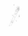
На фиг. 1 показан внешний вид в изометрии части бурильной колонны, содержащей хвостовой переходник, соединенный аксиально одним концом с бурильной штангой посредством соединительного узла с охватываемым и охватывающим элементами.In FIG. 1 shows an isometric view of a portion of a drill string containing a tail adapter connected axially at one end to the drill rod by means of a connecting unit with male and female elements.
На фиг. 2 показан вид в изометрии хвостового переходника фиг. 1 согласно конкретной реализации настоящего изобретения.In FIG. 2 is an isometric view of the tail adapter of FIG. 1 according to a specific implementation of the present invention.
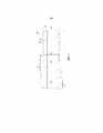
На фиг. 3 показан внешний вид в изометрии соединительного конца с охватываемой втулкой хвостового переходника фиг. 2.In FIG. 3 shows an isometric view of the connecting end with the male tail adapter bush of FIG. 2.
На фиг. 4 показан вид сечения конца с охватываемой втулкой фиг. 3.In FIG. 4 shows a sectional view of the end with the male sleeve of FIG. 3.
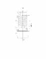
На фиг. 5 показан внешний вид в изометрии соединительного конца с охватываемой втулкой хвостового переходника фиг. 2 согласно дополнительной конкретной реализации настоящего изобретения.In FIG. 5 shows an isometric view of the connecting end with the male tail adapter bush of FIG. 2 according to a further specific implementation of the present invention.
Подробное описание предпочтительного варианта осуществления изобретенияDetailed Description of a Preferred Embodiment
Связанное изобретение описано ниже в виде примера со ссылкой на хвостовой переходник, являющийся компонентом бурильной колонны для создания части бурильной колонны. Понятно что, связанное изобретение применимо для любого удлиненного компонента, имеющего конец в виде охватываемой втулки с контактом на заплечике, выполненный с возможностью образования соединительного узла с резьбовой охватывающей муфтой смежного компонента бурильной колонны. Соответственно, связанное изобретение можно применять для бурильной штанги, бурильной трубы, хвостовика, хвостового переходника, бурового долота, вала или переходника, закрепляемого на ведущем конце бурильной колонны или на конце бурильной колонны, соединяемом с долотом.The related invention is described below by way of example with reference to a tail adapter, which is a component of the drill string to create part of the drill string. It is understood that the related invention is applicable to any elongated component having an end in the form of a male sleeve with a contact on the shoulder, configured to form a connecting unit with a threaded female sleeve of an adjacent component of the drill string. Accordingly, the related invention can be applied to a drill rod, drill pipe, shank, tail adapter, drill bit, shaft or adapter attached to the leading end of the drill string or to the end of the drill string connected to the bit.
Как показано на фиг. 1, бурильная колонна содержит удлиненный хвостовой переходник 100, соединенный аксиально с крайней бурильной штангой 101 посредством резьбового соединения 104, образованного охватываемым резьбовым концом хвостового переходника 100 и охватывающим резьбовым концом бурильной штанги 101. Оба компонента 100, 101 бурильной колонны соединены посредством 'контакта на заплечике' при котором кольцевая боковая поверхность 102 охватываемого соединительного элемента переходника 100 взаимодействует, поддерживая контакт с соответствующей кольцевой боковой поверхностью 103 охватывающей муфты бурильной штанги 101.As shown in FIG. 1, the drill string comprises an
Как показано на фиг. 2, хвостовой переходник 100 содержит секцию 202 основного отрезка длины, имеющую первый конец 200 и второй конец 201, и сконфигурирован для монтажа на ведущем конце бурильной колонны смежно с ударным механизмом посредством второго конца 201. Промывочное отверстие 206 выполнено в секции 202 для обеспечения ввода промывочной текучей среды в центральный канал 205, проходящий аксиально через аксиально переднюю часть отрезка длины переходника 100 между промывочным отверстием 206 и первым концом 200. Главная трубная часть 202 заканчивается к первому концу 200 кольцевым заплечиком 207, который выступает радиально из охватываемой втулки 208, имеющей наружный диаметр меньше соответствующего наружного диаметра заплечика 207 и секции 202 основного отрезка длины. Соответственно, кольцевая боковая поверхность 102 обеспечена на аксиальном стыке между втулкой 208 и заплечиком 207 для обеспечения контакта на заплечике для упора в кольцевую боковую поверхность 103 резьбового охватывающего соединительного элемента. Втулка 208, разделена аксиально на резьбовую часть 204, проходящую аксиально к первому концу 200, и не имеющий резьбы хвостовик 203, расположенный аксиально между резьбовой частью 204 и заплечиком 207.As shown in FIG. 2, the
Как показано на фиг. 3 и 4, не имеющий резьбы хвостовик 203 содержит в общем цилиндрическую зону 302, расположенную аксиально самой близкой к резьбовой части 204, и переходную зону, которая образует аксиальный стык с кольцевой боковой поверхностью 102 заплечика 207. Наружный диаметр не имеющего резьбы хвостовика 203 на переходной зоне увеличивается от цилиндрической зоны 302 до первой криволинейной зоны 300, имеющей первый радиус кривизны, и второй криволинейной зоны 301, имеющей второй радиус кривизны, который меньше первого радиуса кривизны зоны 300. Согласно конкретной реализации, в плоскости, проходящей продольно вдоль втулки 208, кривая линия не имеющего резьбы хвостовика на переходной зоне 300, 301 содержит профиль эллиптической формы. Данная кривая линия на переходной зоне 300, 301 между не имеющим резьбы хвостовиком 203 и заплечиком 207 является предпочтительной для упрочнения втулки 208, для сопротивления изгибающим силам, с которыми сталкивается бурильная колонна во время бурения.As shown in FIG. 3 and 4, a threaded
Резьбовая часть 204, согласно конкретной реализации, содержит форму однозаходной резьбы с одним гребнем, образованным винтовыми витками проходящими аксиально между первым концом 307 резьбы (расположенным к первому концу 200 переходника) и вторым концом 306 резьбы, завершающимся на не имеющем резьбы хвостовике 203. Выполненный, как винтовая линия гребень, соответственно, содержит винтовые витки, имеющие вершины 303 и аксиально между ними впадины 304. Впадины 304 и вершины 303 разделены рабочими сторонами 305, являющимися криволинейными и проходящими в общем поперек продольной оси 309, проходящей через хвостовой переходник 101. Глубина резьбы на первом конце 307 уменьшается вдоль круговой траектории вершины 303 для участка самого дальнего винтового витка аксиально самого близкого к первому концу 200 переходника. Соответственно, первый конец 307 резьбы заканчивается, как гладкий радиальный переход в общем в коническую концевую зону 307 втулки 208, которая, в свою очередь, завершена кольцевой концевой поверхностью на первом конце 200 переходника. Аналогично, второй конец 306 резьбы выполнен, как постепенный радиальный переход в не имеющую резьбы зону 302 хвостовика. То есть, глубина резьбы в самом дальнем винтовом витке на обоих концах 306, 307 резьбы уменьшается, когда наружный диаметр вершины 303 в конечном аксиальном участке каждого самого дальнего винтового витка уменьшается к наружному диаметру не имеющего резьбы хвостовика 203 и конической концевой части 308, соответственно. Постепенное уменьшение в наружном диаметре вершины 303 на концах 307, 306 резьбы является предпочтительным для уменьшения концентраций напряжения на резьбовой части 204 для вклада в увеличенную прочность представленного конца 208 охватываемой втулки.The threaded
Не имеющий резьбы хвостовик 203 имеет аксиальную длину Ls, определенную, как аксиальное расстояние между кольцевой боковой поверхностью 102 и аксиально самым внутренним вторым концом 306 резьбовой части 204. Второй конец 306 резьбы определен, как аксиальная зона, на которой вершина 303 уменьшается до наружного диаметра не имеющего резьбы хвостовика 203. Данное аксиальное положение, соответственно, определено, как зона, где профиль формы сечения охватываемой втулки 208 является круглым, соответствующим цилиндрическому, не имеющему резьбы хвостовику 203 в отличие от не круглого профиля формы сечения резьбовой части 204. Аналогично, аксиальная длина Lt резьбовой части 204 определена, как аксиальное расстояние между первым и вторым концами 307, 306 резьбы. Первый конец 307 резьбы определен, как аксиальное положение, где профиль формы сечения конической части 308 становится круглым.The
Охватываемая втулка 208, также содержит основную аксиальную длину L, определенную, как аксиальное расстояние между кольцевой боковой поверхностью 102 и первым концом 200 переходника. Согласно конкретной реализации, наружный диаметр Ds не имеющего резьбы хвостовика на цилиндрической зоне 302 меньше соответствующего наружного диаметра Dm секции 202 основного отрезка длины и соответствующего наружного диаметра на кольцевом заплечике 207. Диаметр Ds также меньше наружного диаметра Dy резьбовой части 204, соответствующего радиальному положению пика вершины 303 на каждом винтовом витке. Согласно конкретной реализации, Dy является неизменным на аксиальной длине Lt резьбовой части 204, так что резьбовая часть обеспечена в общем на цилиндрической втулке 208. Вместе с тем, понятно, что связанное изобретение является подходящим для конических втулок 208, в частности, с конической резьбовой частью 204.The
Для оптимизации прочности втулки 208 для сопротивления изгибающим силам, с которыми сталкивается бурильная колонна во время ударного бурения, отношение Ls/Dy имеет величину в диапазоне 0,4-1,0 и согласно конкретной реализации составляет 0,5-0,7. Дополнительно, данное упрочнение втулки 208, может быть выражено, как отношение Ls/L с величиной в диапазоне 0,25-0,5 и, в частности, 0,28-0,32. Соответственно, Lt больше Ls. Увеличение аксиальной длины Ls не имеющего резьбы хвостовика 103 является предпочтительным для отделения аксиально резьбовой части 204 от кольцевой боковой поверхности, 102, что обнаружено посредством моделирования, для минимизации напряжения на винтовых витках и, в частности, вершинах 303, впадинах 304 и рабочих сторонах 305 для резьбовых соединений с контактом на заплечике. Соответственно, риск выхода из строя соединительного узла минимизирован и эксплуатационный ресурс компонентов бурильной колонны увеличен.To optimize the strength of the
Дополнительно конкретная реализация охватываемой втулки 208 подробно описана ниже со ссылкой на фиг. 5. Показанный на фиг. 5 вариант отличается от описанного выше варианта осуществления фиг. 2-4, тем, что не имеющий резьбы хвостовик 203 содержит профиль непрерывной криволинейной формы в аксиальном направлении между боковой поверхностью 102 и резьбовым концом 306. Вместе с тем, конфигурация резьбовой части 204, описанная ниже согласно варианту осуществления фиг. 5, применима также для варианта осуществления фиг. 2-4.Additionally, a specific implementation of the
Резьбовая часть 204 выполнена, как в общем цилиндрическая концевая часть на втулке 208 так, что диаметр Dy резьбы между вершиной 303 является в общем неизменным вдоль аксиальной длины резьбовой части 204. Дополнительно, диаметр Di (соответствующий диаметральному расстоянию между радиальными позициями впадин 304) является также, по существу, неизменным вдоль всей аксиальной длины резьбовой части 204 между концами 306, 307 резьбы. Связанное изобретение специально приспособлено для ударных (или ударниковых) компонентов, образующих часть бурильного устройства, и, в частности, бурильной колонны, благодаря конфигурации резьбы на втулке 208. В частности, шаг резьбы может иметь величину в диапазоне 5-50 мм в зависимости от размера (т.e., радиуса) удлиненного компонента. Для оптимизации резьбы для ударного бурения шаговый угол θ может иметь величину в диапазоне 5-10° для соответствующих размеров компонента. Такая конфигурация должна отличаться от резьбовых концов компонента для вращения или зондирования, которые могут обычно содержать резьбу типа API со значительно меньшим шаговым углом порядка 1°. В некоторых реализациях средний диаметр резьбы (расстояние от вершины до вершины) может быть в диапазоне 15-120 мм в зависимости от размера (т.e., радиуса) удлиненного компонента.The threaded
Соответственно, резьба на охватываемой втулке предпочтительно содержит отношение шага (аксиальное расстояние от вершины до вершины)/средний диаметр резьбы, составляющее 0,35-0,55, где средний диаметр резьбы является средним диаметров охватываемого и охватывающего резьбовых концов.Accordingly, the thread on the male sleeve preferably comprises a pitch ratio (axial distance from the top to the top) / average thread diameter of 0.35-0.55, where the average thread diameter is an average of the diameters of the male and female threaded ends.
Представленная охватываемая втулка, также выполнена с возможностью минимизации концентраций напряжения на переходной зоне 300, 301, 500, 501 и 502, благодаря относительным размерам Ds, Di и Td, где Di соответствует диаметральному расстоянию между радиальными позициями впадин 304 (между каждым винтовым гребнем) на диаметрально противоположных сторонах резьбовой части, и Td соответствует глубине резьбы между вершинами 303 и впадинами 304 (в плоскости перпендикулярной продольной оси 309). В частности, концентрации напряжения на переходной зоне 300, 301, 500, 501 и 502 минимизированы, насколько возможно, где Ds меньше Dy и Ds меньше Di. В частности, максимальный диаметр Ds может быть равен Di - Td, и минимальный диаметр Ds может быть равен Di - 4Td. Предпочтительно, Ds приблизительно равен Di - 2Td.The presented male sleeve is also configured to minimize stress concentrations at the
Относительные размеры Ds и Ls, как описано в данном документе, максимизируют аксиальные и радиальные расстояния, на которые переходная зона 300, 301, 500, 501, 502 может продолжаться. В частности, и согласно конфигурации фиг. 5, не имеющий резьбы хвостовик 203 содержит переходную зону, имеющую первый радиус R1 кривизны на части 500, который меньше второго аксиально смежного радиуса R2 кривизны на части 501, который, в свою очередь, меньше аксиально смежного третьего радиуса R3 кривизны на части 502, который, в свою очередь, меньше аксиально смежного четвертого радиуса R4 кривизны на части 504. В частности, радиус R1 на части 500 приблизительно равен половине радиуса R2 на части 501; радиус R2 на части 501 приблизительно равен половине радиуса R3 на части 502, и радиус R3 на части 502 приблизительно равен одно третьей радиуса R4 на части 504. Как проиллюстрировано на фиг. 5, часть 500 расположена аксиально ближе всего к боковой поверхности 102, часть 501 расположена второй от боковой поверхности 102, часть 502 расположена третьей от боковой поверхности 102 и часть 504 расположена самой дальней от боковой поверхности 102. Минимизированный Ds и максимизированный Ls, соответственно, обеспечивают плавный переход между не имеющим резьбы хвостовиком 203 и заплечиком 207. При этом, втулка 208 упрочнена для сопротивления напряжению от изгиба и механическим напряжениям, возникающим в результате передачи действия ударной волны.The relative dimensions of Ds and Ls, as described herein, maximize the axial and radial distances that the
Claims (30)
Translated fromRussianApplications Claiming Priority (3)
| Application Number | Priority Date | Filing Date | Title |
|---|---|---|---|
| EP15168921.3 | 2015-05-22 | ||
| EP15168921.3AEP3095954B1 (en) | 2015-05-22 | 2015-05-22 | Drill rod or adaptor with strengthened spigot coupling |
| PCT/EP2016/061300WO2016188862A1 (en) | 2015-05-22 | 2016-05-19 | Drill rod or adaptor with strengthened spigot coupling |
Publications (3)
| Publication Number | Publication Date |
|---|---|
| RU2017144031A RU2017144031A (en) | 2019-06-24 |
| RU2017144031A3 RU2017144031A3 (en) | 2019-08-06 |
| RU2713548C2true RU2713548C2 (en) | 2020-02-05 |
Family
ID=53191559
Family Applications (1)
| Application Number | Title | Priority Date | Filing Date |
|---|---|---|---|
| RU2017144031ARU2713548C2 (en) | 2015-05-22 | 2016-05-19 | Drilling rod or adapter with reinforced connecting element in form of bushing |
Country Status (14)
| Country | Link |
|---|---|
| US (1) | US11162619B2 (en) |
| EP (3) | EP3095954B1 (en) |
| CN (1) | CN107683363B (en) |
| AU (1) | AU2016266604B2 (en) |
| BR (1) | BR112017024932B1 (en) |
| CA (1) | CA2986624C (en) |
| CL (1) | CL2017002940A1 (en) |
| MX (1) | MX389505B (en) |
| PE (1) | PE20180718A1 (en) |
| PL (2) | PL3095954T3 (en) |
| PT (1) | PT3298229T (en) |
| RU (1) | RU2713548C2 (en) |
| WO (1) | WO2016188862A1 (en) |
| ZA (1) | ZA201707459B (en) |
Families Citing this family (12)
| Publication number | Priority date | Publication date | Assignee | Title |
|---|---|---|---|---|
| EP2845991B1 (en) | 2013-09-09 | 2015-11-18 | Sandvik Intellectual Property AB | Drill string rod with strengthened spigot coupling |
| EP3095954B1 (en) | 2015-05-22 | 2024-05-15 | Sandvik Intellectual Property AB | Drill rod or adaptor with strengthened spigot coupling |
| US20180100356A1 (en)* | 2016-10-10 | 2018-04-12 | Padley & Venables Limited | Drill Rod |
| PT3536894T (en) | 2018-03-09 | 2020-11-19 | Sandvik Mining And Construction Tools Ab | Coupling for connecting downhole tubulars |
| PL3663506T3 (en)* | 2018-12-03 | 2023-03-13 | Sandvik Mining And Construction G.M.B.H. | A drilling string, threaded coupling, and rod adaptor for rotary drilling |
| EP3712374B1 (en)* | 2019-03-18 | 2022-09-28 | Sandvik Mining and Construction Tools AB | Drill string rod |
| JP7677958B2 (en)* | 2019-10-11 | 2025-05-15 | サンドヴィック マイニング アンド コンストラクション ツールズ アクティエボラーグ | Drilling assembly with protected shoulder |
| FI3879065T3 (en)* | 2020-03-11 | 2023-01-13 | Elliptical design for male thread clearance | |
| EP3933165A1 (en)* | 2020-06-30 | 2022-01-05 | Sandvik Mining and Construction Tools AB | Thread clearance |
| PL3971385T3 (en) | 2020-09-17 | 2023-07-31 | Sandvik Mining And Construction Tools Ab | Drill string joint design |
| EP4047178B1 (en)* | 2021-02-17 | 2023-09-13 | Sandvik Mining and Construction Tools AB | Elliptical design for hexagonal shanks |
| EP4047179B1 (en)* | 2021-02-17 | 2023-09-13 | Sandvik Mining and Construction Tools AB | Elliptical design for shank adapters |
Citations (6)
| Publication number | Priority date | Publication date | Assignee | Title |
|---|---|---|---|---|
| US1926925A (en)* | 1931-04-07 | 1933-09-12 | Gulf Res & Dev Corp | Pin, bolt, and other connecting device |
| US3537738A (en)* | 1968-04-15 | 1970-11-03 | Sandvikens Jernverks Ab | Drill rod for long hole drilling in the ground |
| US6164392A (en)* | 1999-04-26 | 2000-12-26 | Sandvik Ab | Percussive drilling apparatus |
| RU2247219C2 (en)* | 2000-03-02 | 2005-02-27 | САНДВИК АБ (пабл) | Threaded connection and drilling tool element |
| WO2008150207A1 (en)* | 2007-06-05 | 2008-12-11 | Sandvik Intellectual Property Ab | Rock-drilling equipment as well as female and male parts therefor |
| EP2845992B1 (en)* | 2013-09-09 | 2016-01-13 | Sandvik Intellectual Property AB | Drill string with bend resistant coupling |
Family Cites Families (17)
| Publication number | Priority date | Publication date | Assignee | Title |
|---|---|---|---|---|
| US4548431A (en)* | 1981-12-17 | 1985-10-22 | Hughes Tool Company - Usa | Tool joint with internal/external make-up shoulders |
| US5169183A (en)* | 1987-05-12 | 1992-12-08 | Diamant Boart Stratabit S.A. | Threaded joint for drill rod elements |
| SE469603B (en) | 1988-07-08 | 1993-08-02 | Sandvik Ab | GAENGFOERBAND |
| USH1329H (en)* | 1992-04-28 | 1994-07-05 | Exxon Production Research Company | Drill collar connections |
| SE505073C2 (en) | 1994-07-19 | 1997-06-23 | Sandvik Ab | Threaded joints for striking drilling |
| US5492375A (en)* | 1994-07-21 | 1996-02-20 | Grant Tfw, Inc. | Drill pipe with improved connectors |
| AUPO445897A0 (en)* | 1997-01-06 | 1997-01-30 | Boart Longyear Inc. | Straight hole drilling system |
| CA2303710C (en) | 1997-01-06 | 2005-11-08 | Boart Longyear Inc. | Straight hole drilling system |
| GB2340148B (en) | 1998-07-30 | 2002-12-31 | Boart Longyear Ltd | Tube rod |
| SE515517C2 (en) | 1998-09-28 | 2001-08-20 | Uniroc Ab | String drill string thread for striking rock drilling |
| SE516651C2 (en) | 1999-11-26 | 2002-02-05 | Sandvik Ab | Threaded joints for striking drilling, a trade and a female part |
| CA2652278A1 (en) | 2006-05-17 | 2007-11-22 | Sandvik Intellectual Property Ab | A top hammer rock-drilling tool, a drill rod and coupling sleeve |
| US20100018699A1 (en)* | 2007-03-21 | 2010-01-28 | Hall David R | Low Stress Threadform with a Non-conic Section Curve |
| JP5523373B2 (en) | 2011-02-18 | 2014-06-18 | 三菱マテリアル株式会社 | Hollow steel rod for excavation and manufacturing method thereof |
| EP2845991B1 (en)* | 2013-09-09 | 2015-11-18 | Sandvik Intellectual Property AB | Drill string rod with strengthened spigot coupling |
| EP2845993B1 (en)* | 2013-09-09 | 2018-01-10 | Sandvik Intellectual Property AB | Energy transmission efficient percussive drill string coupling |
| EP3095954B1 (en) | 2015-05-22 | 2024-05-15 | Sandvik Intellectual Property AB | Drill rod or adaptor with strengthened spigot coupling |
- 2015
- 2015-05-22EPEP15168921.3Apatent/EP3095954B1/ennot_activeRevoked
- 2015-05-22PLPL15168921.3Tpatent/PL3095954T3/enunknown
- 2015-05-22EPEP24168119.6Apatent/EP4386247A3/enactivePending
- 2016
- 2016-05-19CACA2986624Apatent/CA2986624C/enactiveActive
- 2016-05-19MXMX2017014879Apatent/MX389505B/enunknown
- 2016-05-19PLPL16725462Tpatent/PL3298229T3/enunknown
- 2016-05-19USUS15/576,113patent/US11162619B2/enactiveActive
- 2016-05-19RURU2017144031Apatent/RU2713548C2/enactive
- 2016-05-19BRBR112017024932-4Apatent/BR112017024932B1/enactiveIP Right Grant
- 2016-05-19EPEP16725462.2Apatent/EP3298229B1/enactiveActive
- 2016-05-19PTPT167254622Tpatent/PT3298229T/enunknown
- 2016-05-19AUAU2016266604Apatent/AU2016266604B2/enactiveActive
- 2016-05-19PEPE2017002428Apatent/PE20180718A1/enunknown
- 2016-05-19CNCN201680029400.2Apatent/CN107683363B/enactiveActive
- 2016-05-19WOPCT/EP2016/061300patent/WO2016188862A1/ennot_activeCeased
- 2017
- 2017-11-03ZAZA2017/07459Apatent/ZA201707459B/enunknown
- 2017-11-20CLCL2017002940Apatent/CL2017002940A1/enunknown
Patent Citations (6)
| Publication number | Priority date | Publication date | Assignee | Title |
|---|---|---|---|---|
| US1926925A (en)* | 1931-04-07 | 1933-09-12 | Gulf Res & Dev Corp | Pin, bolt, and other connecting device |
| US3537738A (en)* | 1968-04-15 | 1970-11-03 | Sandvikens Jernverks Ab | Drill rod for long hole drilling in the ground |
| US6164392A (en)* | 1999-04-26 | 2000-12-26 | Sandvik Ab | Percussive drilling apparatus |
| RU2247219C2 (en)* | 2000-03-02 | 2005-02-27 | САНДВИК АБ (пабл) | Threaded connection and drilling tool element |
| WO2008150207A1 (en)* | 2007-06-05 | 2008-12-11 | Sandvik Intellectual Property Ab | Rock-drilling equipment as well as female and male parts therefor |
| EP2845992B1 (en)* | 2013-09-09 | 2016-01-13 | Sandvik Intellectual Property AB | Drill string with bend resistant coupling |
Also Published As
| Publication number | Publication date |
|---|---|
| EP3095954B1 (en) | 2024-05-15 |
| BR112017024932A2 (en) | 2018-07-31 |
| AU2016266604A1 (en) | 2017-12-07 |
| MX2017014879A (en) | 2018-04-20 |
| US11162619B2 (en) | 2021-11-02 |
| RU2017144031A (en) | 2019-06-24 |
| CN107683363A (en) | 2018-02-09 |
| EP3095954C0 (en) | 2024-05-15 |
| PL3298229T3 (en) | 2021-02-08 |
| WO2016188862A1 (en) | 2016-12-01 |
| EP3298229B1 (en) | 2020-10-14 |
| ZA201707459B (en) | 2021-05-26 |
| US20180135782A1 (en) | 2018-05-17 |
| EP3095954A1 (en) | 2016-11-23 |
| RU2017144031A3 (en) | 2019-08-06 |
| PL3095954T3 (en) | 2024-08-05 |
| EP3298229A1 (en) | 2018-03-28 |
| AU2016266604B2 (en) | 2020-09-10 |
| MX389505B (en) | 2025-03-20 |
| EP4386247A2 (en) | 2024-06-19 |
| BR112017024932B1 (en) | 2023-02-28 |
| CA2986624C (en) | 2023-04-25 |
| CA2986624A1 (en) | 2016-12-01 |
| PT3298229T (en) | 2020-11-19 |
| EP4386247A3 (en) | 2024-09-25 |
| PE20180718A1 (en) | 2018-04-26 |
| CN107683363B (en) | 2024-07-12 |
| CL2017002940A1 (en) | 2018-03-16 |
Similar Documents
| Publication | Publication Date | Title |
|---|---|---|
| RU2713548C2 (en) | Drilling rod or adapter with reinforced connecting element in form of bushing | |
| RU2714405C2 (en) | Threaded connecting end for component of drill string | |
| EP2845992B1 (en) | Drill string with bend resistant coupling | |
| EP2845991B1 (en) | Drill string rod with strengthened spigot coupling | |
| US11808086B2 (en) | Drill string rod | |
| EP3819458B1 (en) | Strengthened percussive drill string female coupling | |
| AU2021346124A1 (en) | Drill string joint design | |
| OA20379A (en) | Drill string rod. | |
| AU2019394564A1 (en) | A drilling string, threaded coupling, and rod adaptor for rotary drilling |